hydraulic analysis of sthe using bell delaware method p m v subbarao professor mechanical...
TRANSCRIPT

Hydraulic Analysis of STHE Using Bell Delaware Method
P M V SubbaraoProfessor
Mechanical Engineering Department
I I T Delhi
Five corrections to Cross Flow Pressure Drop…..

Bell-Delaware Model Shell-side heat transfer coefficient
Where hi is heat transfer coefficient for ideal cross flow past a tube bank.
rsblcis JJJJJhh
Jc : Segmental baffle window correction factor Jl : Correction factor for baffle leakage effects for heat transferJb : Correction factor for bundle bypass effects for heat transfer Js : Heat transfer correction for unequal baffle spacing at inlet and/or outlet.Jr: Correction factor for adverse temperature gradient in laminar flow

Shell side Fluid Flow in STHE

Network of Sub-flows with Same Pressure Drop

Experiments of Delaware
• Delaware’s fundamental experimental work developed the correlations for calculating the pressure drop for a single ideal cross-flow section as well as for a single ideal window section.
• Further studies indicated:
• a) that the pressure drop across the inlet and exit sections was affected (reduced) by bundle bypass but not by baffle leakage,
• b) that the pressure drop across internal crossflow sections was affected by both bundle bypass and baffle leakage, and
• c) that the pressure drop through a window was affected by baffle leakage but not by bypass.

The Structure of Hydraulic Analysis
• The calculational structure is to;
• calculate the ideal crossflow and window pressure drops,
• correct each of those terms by the effective correction factors,
• then multiply the effective pressure drops by the number of sections of that kind found in the exchanger, and
• finally to sum the effects to give the total shell side pressure drop (exclusive of nozzles.)
• If the resulting value is satisfactory, the exchanger is designed at least from a shell-side thermal-hydraulic point of view.
• If the required pressure drop is too large, it is necessary to redesign the exchanger, probably using a larger shell diameter.
• If the calculated pressure drop is much below the allowable, it is probably possible to reduce the shell diameter and redesign to a smaller and probably less expensive heat exchanger.

Shell-side pressure drop, Δps
• For a shell-and-tube type heat exchanger with bypass and leakage streams, the total inlet nozzle-to- exit nozzle pressure drop is calculated as the sum of the following three components:
• The combined pressure drop of all the interior cross flow section .
• The pressure drop in the window
• The pressure drop in the entrance and exit sections.
• The total shell-side pressure drop, excluding nozzles, is
•The pressure drop in the nozzles must be calculated separately and added to the total pressure drop.

Friction coefficient for Ideal Cross Flow
2Re33.1
1b
s
b
o
Ti
dP
bf
Where 43
Re14.01 bs
bb


Pressure drop in Ideal Interior Cross Flow
• The pressure drop in an equivalent ideal tube bank in one baffle compartment of central baffle spacing a is calculated from:
where fi is the friction coefficient,Gs is the mass velocity of the shell-side fluid, ρs is the shell-side fluid density, μs is the shell-side fluid viscosity, μs,w is the viscosity of shell-side fluid evaluated at wall surface temperature, and Ntcc is the number of tube rows crossed in one cross flow section.
2
sin
3602121 ctlctl
twCtubestcc FFNN
Pressure drop in the interior cross flow
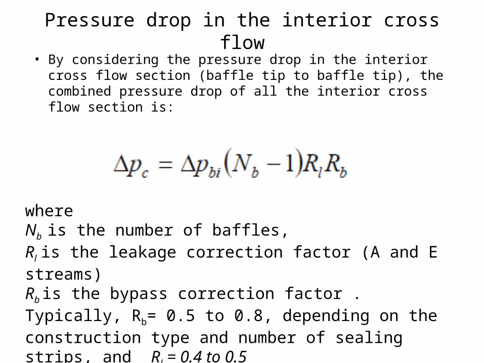
• By considering the pressure drop in the interior cross flow section (baffle tip to baffle tip), the combined pressure drop of all the interior cross flow section is:
where Nb is the number of baffles,Rl is the leakage correction factor (A and E streams) Rb is the bypass correction factor . Typically, Rb= 0.5 to 0.8, depending on the construction type and number of sealing strips, and Rl = 0.4 to 0.5

The pressure drop in the window
• The pressure drop in the window is affected by leakage but not bypass.
• The combined pressure drop in all the windows crossed equals Δpw
• The Delaware method offers two different correlations for ,
• one for turbulent flow and
• one for laminar flow.
• For simplicity the correlations are derived based on the shell-side cross flow Res.
• Both correlations employ modified mass velocity.

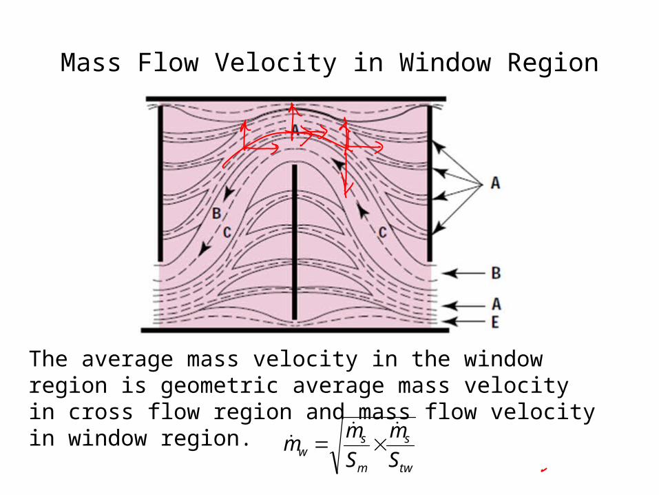
Mass Flow Velocity in Window Region
• The flow in window region is controlled by a baffle tip.

Gross Baffle Window Area
O
A
B
CD
ds/2
Baffle window area = Sector area OABCO – Triangle area OADCO
2cos
2sin
2
12
36042 ds
sds
sds
swg DDDS
2
sin
36042 dsdsswg DS
Gross Fraction of Baffle window area :
2
sin
360dsds
wgF

Net Baffle Window Flow Area
Net Window flow area = Gross window area – area occupied by tubes in window region.
2
, 4 otwwgnetw dNSS
where Ntwis the number of tubes in the window and is expressed as
2
4Shell theof Area Tube
area tubeWindow
ctlt
twtw
DN
NF
2
sin
360ctlctl
twF
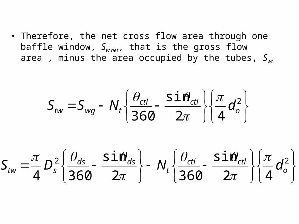
• Therefore, the net cross flow area through one baffle window, Sw net, that is the gross flow area , minus the area occupied by the tubes, Swt
2
42
sin
360 octlctl
twgtw dNSS
22
42
sin
3602
sin
3604 octlctl
tdsds
stw dNDS
Mass Flow Velocity in Window Region
The average mass velocity in the window region is geometric average mass velocity in cross flow region and mass flow velocity in window region.
tw
s
m
sw S
m
S
mm

Turbulent flow through the Window
For turbulent flow, Res >100, the combined pressure drop in all the windows of a STHE is:
•The factor 2 accounts for velocity heads due to the window turnaround, and •0.6 accounts for the cross flow frictional effects over Ntcw which is the number of tube rows crossed in the window.

Laminar flow through the Window
Delware’s experimental research revealed that the structure of laminar flow is dominated by developing
conditions and a strong function of characteristic length of the window.
Equivalent hydraulic diameter of a segmental baffle window
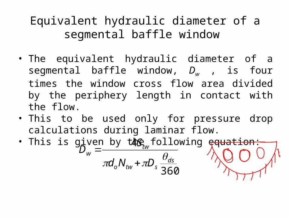
• The equivalent hydraulic diameter of a segmental baffle window, Dw , is four times the window cross flow area divided by the periphery length in contact with the flow.
• This to be used only for pressure drop calculations during laminar flow.
• This is given by the following equation:
360
4
dsstwo
tww
DNd
SD

Pressure Drop for Laminar flow through the Window
• The first term in brackets accounts for the cross flow and longitudinal friction, respectively;
• the second term in brackets represents two velocity heads for the turnaround in the window.
• It should be noted that only the leakage correction factor is applied to the baffle window Δpw, whereas the bypass correction factor is considered not applicable.
For laminar flow, Res< 100:

Pressure Drop in Window for Res=100
• Comparing the results of laminar and turbulent calculations at the break point of Res=100, it is found that the values are not equal.
• Because they are based on different principles. • In such cases, the larger value should be taken as a
safety factor.
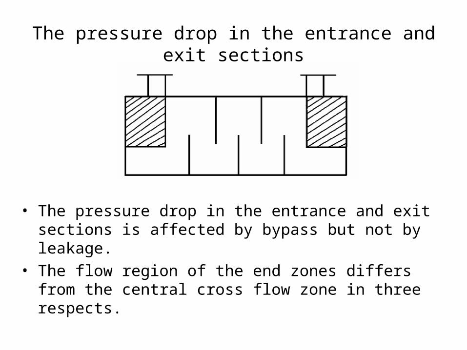
The pressure drop in the entrance and exit sections
• The pressure drop in the entrance and exit sections is affected by bypass but not by leakage.
• The flow region of the end zones differs from the central cross flow zone in three respects.

Special Features of Flow Region of the End Zones
• The number of tube rows crossed includes the tube rows in the entry or exit window.
• The leakage streams have not yet developed (entry) or just joined the main stream (outlet) in the end zones, and therefore the leakage correction factor is not applicable.
• The baffle spacing in the end zones may differ from the central spacing, especially for U-tube bundles.
• An end zone correction factor, Rs is therefore used.
• The pressure drop in the two end zones is
Models for Correction Factors R….
Leakage Flow Streams
• There are two different shell side leakage flow streams in a baffled heat exchanger
• Stream A is the leakage stream in the orifice formed by the clearance between the baffle tube hole and the tube wall.
• Stream E is the leakage stream between the baffle edge and shell wall.

Leakage Streams A &E
Flow areas for stream A.

The leakage correction factor, Rl
Where

Correction factors for bundle bypass pressure drop, Rb
with the limit of , Rb =1 at rss >1/2 & Cbp=4.5 for laminar flow, Res≤ 100,
Cbp=3.7 for turbulent and transition flow.

Pressure drop correction for unequal baffle spacing at inlet and/or outlet, Rs


Bell-Delaware Model Shell-side Flow
rsblcis JJJJJhh
sbeilwiblbis RRpRpRRpp