hydralift - hysecurity€¦ · 6 hysecurity.com | 800-321-9947 hydralift programming and operations...
TRANSCRIPT

Programming and Operations Manual
HydraLift™
10, 10F, 20, 20FVehicular vertical lift gate operator with Smart Touch Controller

MX4512 Rev. D ©20202 hysecurity.com | 800-321-9947 HydraLift Programming and Operations
(This page intentionally blank)

MX4512 Rev. D ©2020 HydraLift Programming and Operations hysecurity.com | 800-321-9947 3
TABLE OF CONTENTS
HydraLift:Table of Contents .......................................... 3Introduction ................................................... 5Models and Features ..................................... 6Stopping the Gate ........................................................7Starting the Gate ..........................................................7
Safety Information ......................................... 9Installation Preparation & Process ............. 17Installation Preparation Checklist ..............................17Installation Process Overview ....................................17
HVG Pump and Electrical Panel .................. 18HVG 420 Post Plan and Dimensions .........................19HVG 460 Post Plan and Dimensions .........................20Field Hose Measurements for HVG Operators ..........21
Installation ................................................... 22Limit Switch Setting/Wiring ........................................25Hose Connections......................................................26Manual Operation ......................................................27
Operations.................................................... 27Mechanical & Hydraulic Adjustments ..........................28Smart Touch Controller ................................................29STC Installation Configuration ...................................30STC Wiring Control Inputs .........................................31Smart Touch Controller Inputs ...................................31
Dual Gate ..................................................... 33STC Controller User Menu .......................... 34Initial Power Up ..........................................................34System Data and User Menu Settings: ......................34
User Menu Function Descriptions ..............................38Installer Menu Function Descriptions ........................39User Programmable Output Relays 1-3 .....................42Clock Functions .........................................................44Setting the Time and Date .........................................44
Entrapment Protection Device Schem. ....... 45UL 325 Device Standard Requirements ......................46Secondary Pedestrian Entrapment..............................47Gate Reversing Edge Sensor Installation....................48General Information: ..................................................49Compatibility: .............................................................49Installation: .................................................................49Configuration:.............................................................49Connection: ................................................................49Supervised Connection: .............................................49
Install Photo Eye (Non-Contact) Sensors .... 49Photo Eye Function:...................................................50Alignment: ..................................................................50Detector Basics ..........................................................51Loop Configurations ...................................................51Rules to Follow for Security Gate Applications ..........51
Detector Installation Guide ......................... 51Detector Logic ............................................................52
Loop Diagnostics .......................................................52Test #1: ......................................................................52Test #2: ......................................................................52
Vehicle Detector Loop Layout ..................... 53Vehicle Detector Installation Options ...........................54Hy5B Vehicle Detector Installation .............................55Standard 11 Pin Box Type Vehicle Detector Install ....56Frequency: .................................................................57Changing the Loop Frequency: .................................57
Detector & Loop Fault Diagnostics ............ 57Call Strength Level:....................................................58Standard and Anti-tailgate modes ..............................59
Vehicle Detector Config & Anti-Tailgate .......................59STC 24hr/7day Timer Connection ...............................60Selecting AM/PM or Military Time ..............................60Setting the Time .........................................................60Programming 24 hours or 7 day schedules ...............60Reviewing Programs ..................................................61Manual Override ........................................................61
STC 24hr/7day Timer Connection ...............................61Connecting a Radio Receiver ......................................62Trouble With Gate Movement in General: .................63Electrical Problems in General:..................................63Specific Types of Problems: .......................................63
Troubleshooting ........................................... 63Operator Post.............................................................67Hydraulic System .......................................................67
General Maintenance: ................................. 67Electrical Controls ......................................................68Pressure Relief Valves Adjustment Procedures .........68Vertical Gate Operator Maintenance Schedule .........69
Maintenance Schedule ................................................69D.C. Operator Wiring & Control Config........................71Battery Connection Diagram .......................................72Wire Size Schedules ...................................................74HVG Pump Packs - Parts BReakout .........................76HVG EX Pump Packs - Parts Breakout .......................77Parts Breakout – HVG Control Box .............................78Parts Breakout - DC Power Supply .............................79Appendix A - French Translations ............... 83Warranty ....................................................... 87Specifications .............................................. 88
NOTICEVisit https://hysecurity.com/technical-support/ for installation manuals, replacement part instructions, part diagrams and more.
MX4512 Rev. D ©20204 hysecurity.com | 800-321-9947 HydraLift Programming and Operations
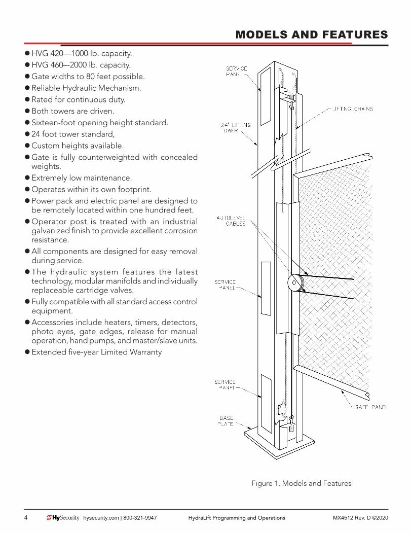
MODELS AND FEATURES zHVG 420—1000 lb. capacity. zHVG 460–-2000 lb. capacity. zGate widths to 80 feet possible. zReliable Hydraulic Mechanism. zRated for continuous duty. zBoth towers are driven. zSixteen-foot opening height standard. z24 foot tower standard, zCustom heights available. zGate is fully counterweighted with concealed weights. zExtremely low maintenance. zOperates within its own footprint. zPower pack and electric panel are designed to be remotely located within one hundred feet. zOperator post is treated with an industrial galvanized finish to provide excellent corrosion resistance. zAll components are designed for easy removal during service. zThe hydraulic system features the latest technology, modular manifolds and individually replaceable cartridge valves. zFully compatible with all standard access control equipment. zAccessories include heaters, timers, detectors, photo eyes, gate edges, release for manual operation, hand pumps, and master/slave units. zExtended five-year Limited Warranty
Figure 1. Models and Features

MX4512 Rev. D ©2020 HydraLift Programming and Operations hysecurity.com | 800-321-9947 5
MODELS AND FEATURESVertical lift gates solve many problems that vex security designers. Vertical lift gates need no extra room to swing or slide, and are extremely very reliable because of the simple drive mechanism in each post. Vertical movement is another design advantage since a very large gate panel can be opened and closed in only sixteen seconds. A vertical lift gate is also very secure and is therefore an excellent choice for a prison application. We can accommodate gates up to 80’ in width and 2,000 pounds. Our standard vertical travel is sixteen feet to allow clearance for trucks. No other design is this flexible.
Only the finest materials and workmanship go into our hydraulic vertical lift towers. They are steel construction, finished with zinc coating for corrosion protection, and come pre-assembled, ready to installbetween buildings or in other tight areas where space is at a premium. All hardware is enclosed and protected from the elements. The vertical lift operators can handle gate weights up to one ton. All units are fully counterweighted and, like all Hy-Security equipment, self-locking.
Take a moment to identify the operator model you have and note there are some changes in the instructions, especially in regards to final adjustments. The following chart shows the differences at a glance:
Table 1. Models and Features
Operator HVG 420 / HVG 420 DS
HVG 420 EX / HVG 420 DX
HVG 460 / HVG 460 DS
HVG 460 EX / HVG 460 DX
Gate Panel Capacity
1000 lbs. 1000 lbs. 2000 lbs. 2000 lbs.
Horsepower 2 HP 5 HP 2 HP 5 HPRate of Travel 1 1 ft/sec 2 ft/sec 1 ft/sec 2 ft/secUL Usage Class 1-4 3-4 1-4 3-4Warranty 5 years 5 years 5 years 5 yearsSoft Stop Yes Yes Yes YesBrake Valves Yes Yes Yes YesSoft Start No Yes No YesTower Size
Post HeightDiameter
Opening ht: 16 ft.24 ft.10 in2
Opening ht: 16 ft.24 ft.10 in2
Opening ht: 16 ft.24 ft.10 in2
Opening ht: 16 ft.24 ft.10 in2
STOPPING THE GATE
All models employ a time delay Soft Stop system. Additionally, hydraulic brake valves (shown at right) are used to control the stopping of heavy or fast moving gates. These valves are exclusive to Hy-Security operators. They are independently adjustable to allow the gate to stop predictably and without banging.
STARTING THE GATE
When starting very heavy gates to accelerate faster than one foot per second, it is necessary to Soft Start the load gently, in addition to stopping it smoothly. Soft Start is accomplished by another Hy-Security exclusive feature we call an AWOG, which diverts some of the start-up hydraulic flow and thereby allows the gate to accelerate over a period of about 2 seconds. This is much like letting your foot slowly off a car clutch – no lurching when the gate starts. The AWOG definitely improves the life and performance of a gate system and never needs adjustment.

MX4512 Rev. D ©20206 hysecurity.com | 800-321-9947 HydraLift Programming and Operations
MODELS AND FEATURESDesigned for Large Gates
More secure and reliable than a cantilever slide gate system. A perfect solution for large gates with limited space to open.
Fast Opening
Standard operator clears a sixteen-foot opening in sixteen seconds—The EX version clears the same opening in just eight seconds.
Reliable in Snowy Conditions
Snowdrifts can’t stop a vertical lift gate from opening.
Smooth Operation
Autolevel system prevents gate becoming wedged or jammed.
Remote Power Pack
Hydraulic Power pack and electric panel remotely located up to 100’ from post.
Heavy Duty Lifting
HVG 420 lifts up to 1000 pounds, HVG 460 lifts up to 2000 pounds.
Built to Last with Quality Components
Time lost to maintenance and repairs is drastically reduced.
Versatile
Ideal for installations with restricted side space. Widths determined only by construction of gate panel and total weight.
Extraordinarily Secure
Vertical Lift Operators are widely used in prisons and other secure facilities.
DC 24-Volt UPS (Uninterruptible Power Supply) Operators
These gate operators function from 24 Volts DC Batteries all of the time to achieve a true UPS system. Our Uninterruptible Power Supply is the most certain way to know that your gate will work when the local AC power fails. This system features fully sealed maintenance free batteries in a separate insulated and ventilated enclosure. A two-battery version provides at least 3,000 feet of backup gate travel. A fourbattery version provides at least 8,000 feet of backup travel during local power loss.
The Smart Touch Controller
This is the brain of the all Hy-Security’s automatic operators. Truly high technology, but is also very rugged to reliably serve in the harsh environments that exist in the real world. The Smart Touch Controller is also very smart and can quickly be configured by an installer or user to adapt to about any functional requirement of a specific site. All system settings are performed with the use of just four programming buttons and an LCD display. The Smart Touch Controller has no switches of any type to set. An RS232 port is for external communication is standard. The system also has a real time clock and an EEPROM to record system events. The log of events can be downloaded from the RS232 port with a PC computer or a PDA with the Palm OS. Our optional vehicle detector modules set a new industry standard by communicating a host of valuable performance data to the microprocessor in the Smart Touch Controller via a serial data stream, allowing user-friendly diagnostics.
MX4512 Rev. D ©2020 HydraLift Programming and Operations hysecurity.com | 800-321-9947 7
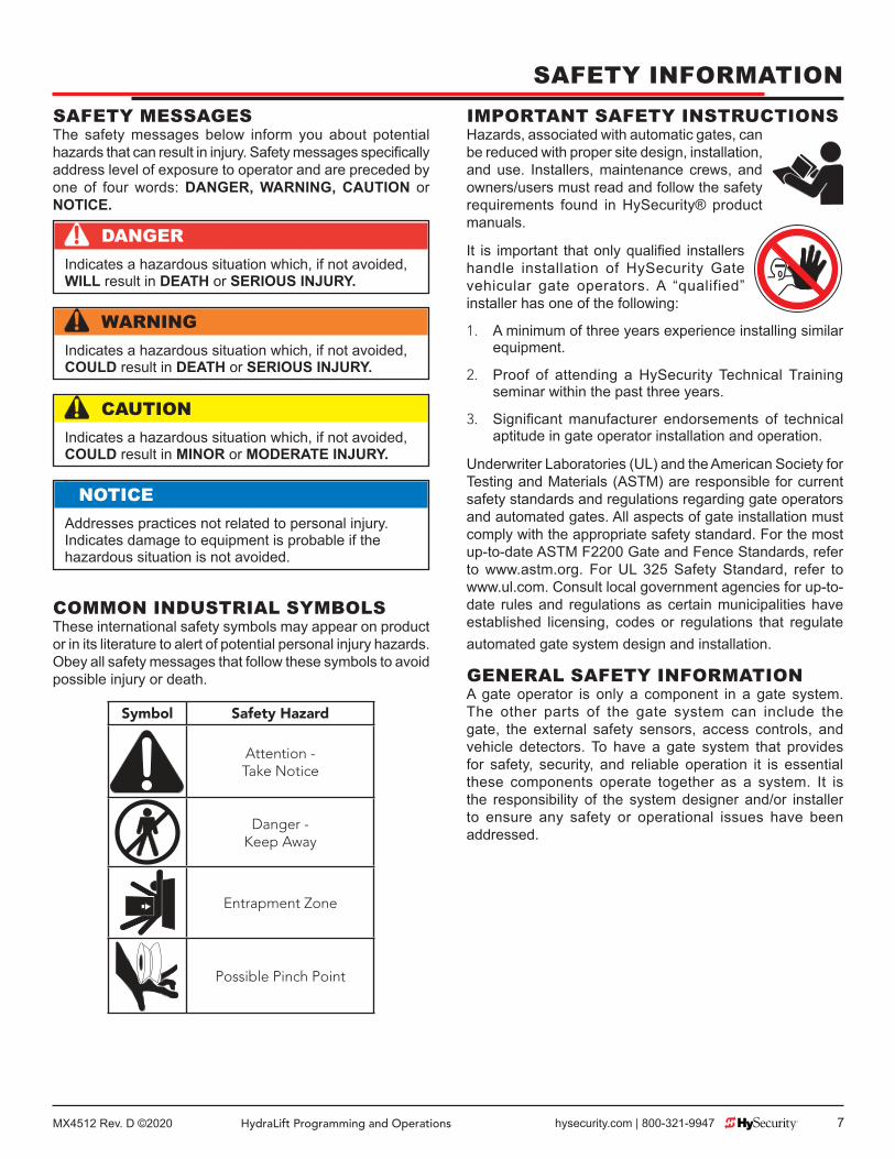
SAFETY MESSAGESThe safety messages below inform you about potential hazards that can result in injury. Safety messages specifi cally address level of exposure to operator and are preceded by one of four words: DANGER, WARNING, CAUTION or NOTICE.
COMMON INDUSTRIAL SYMBOLSThese international safety symbols may appear on product or in its literature to alert of potential personal injury hazards. Obey all safety messages that follow these symbols to avoid possible injury or death.
Symbol Safety Hazard
Attention -Take Notice
Danger -Keep Away
Entrapment Zone
Possible Pinch Point
DANGERIndicates a hazardous situation which, if not avoided, WILL result in DEATH or SERIOUS INJURY.
WARNINGIndicates a hazardous situation which, if not avoided, COULD result in DEATH or SERIOUS INJURY.
CAUTIONIndicates a hazardous situation which, if not avoided, COULD result in MINOR or MODERATE INJURY.
NOTICEAddresses practices not related to personal injury. Indicates damage to equipment is probable if the hazardous situation is not avoided.
IMPORTANT SAFETY INSTRUCTIONSHazards, associated with automatic gates, can be reduced with proper site design, installation, and use. Installers, maintenance crews, and owners/users must read and follow the safety requirements found in HySecurity® product manuals.
It is important that only qualifi ed installers handle installation of HySecurity Gate vehicular gate operators. A “qualified” installer has one of the following:
1. A minimum of three years experience installing similar equipment.
2. Proof of attending a HySecurity Technical Training seminar within the past three years.
3. Signifi cant manufacturer endorsements of technical aptitude in gate operator installation and operation.
Underwriter Laboratories (UL) and the American Society for Testing and Materials (ASTM) are responsible for current safety standards and regulations regarding gate operators and automated gates. All aspects of gate installation must comply with the appropriate safety standard. For the most up-to-date ASTM F2200 Gate and Fence Standards, refer to www.astm.org. For UL 325 Safety Standard, refer to www.ul.com. Consult local government agencies for up-to-date rules and regulations as certain municipalities have established licensing, codes or regulations that regulate automated gate system design and installation.
GENERAL SAFETY INFORMATIONA gate operator is only a component in a gate system. The other parts of the gate system can include the gate, the external safety sensors, access controls, and vehicle detectors. To have a gate system that provides for safety, security, and reliable operation it is essential these components operate together as a system. It is the responsibility of the system designer and/or installer to ensure any safety or operational issues have been addressed.
SAFETY INFORMATION
MX4512 Rev. D ©20208 hysecurity.com | 800-321-9947 HydraLift Programming and Operations
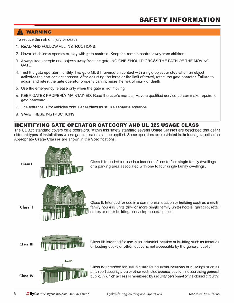
WARNINGTo reduce the risk of injury or death:
1. READ AND FOLLOW ALL INSTRUCTIONS.
2. Never let children operate or play with gate controls. Keep the remote control away from children.
3. Always keep people and objects away from the gate. NO ONE SHOULD CROSS THE PATH OF THE MOVING GATE.
4. Test the gate operator monthly. The gate MUST reverse on contact with a rigid object or stop when an object activates the non-contact sensors. After adjusting the force or the limit of travel, retest the gate operator. Failure to adjust and retest the gate operator properly can increase the risk of injury or death.
5. Use the emergency release only when the gate is not moving.
6. KEEP GATES PROPERLY MAINTAINED. Read the user’s manual. Have a qualifi ed service person make repairs to gate hardware.
7. The entrance is for vehicles only. Pedestrians must use separate entrance.
8. SAVE THESE INSTRUCTIONS.
IDENTIFYING GATE OPERATOR CATEGORY AND UL 325 USAGE CLASSThe UL 325 standard covers gate operators. Within this safety standard several Usage Classes are described that defi ne diff erent types of installations where gate operators can be applied. Some operators are restricted in their usage application. Appropriate Usage Classes are shown in the Specifi cations.
Class IClass I: Intended for use in a location of one to four single family dwellings or a parking area associated with one to four single family dwellings.
Class IIClass II: Intended for use in a commercial location or building such as a multi-family housing units (fi ve or more single family units) hotels, garages, retail stores or other buildings servicing general public.
Class IIIClass III: Intended for use in an industrial location or building such as factories or loading docks or other locations not accessible by the general public.
Class IV
Class IV: Intended for use in guarded industrial locations or buildings such as an airport security area or other restricted access location, not servicing general public, in which access is monitored by security personnel or via closed circuitry.
SAFETY INFORMATION

MX4512 Rev. D ©2020 HydraLift Programming and Operations hysecurity.com | 800-321-9947 9
VEHICULAR TRAFFIC ONLY
WARNING
This automatic gate operator is not designed nor is it intended for pedestrian traffi c. Vehicular gate operators must by their nature be powerful to function reliably. This power can cause injury or death. Accordingly, direct all pedestrian traffi c to a separate walk-through gate.
Install this gate operator only when:
z The operator is appropriate for the construction of the gate and the usage Class of the gate.
z All openings of a horizontal slide gate are guarded or screened from the bottom of the gate to a minimum of 1.83 m (6 ft) above the ground to prevent a 57.2 mm (2-1/4 in) diameter sphere from passing through the openings anywhere in the gate, and in that portion of the adjacent fence that the gate covers in the open position.
z All exposed pinch points are eliminated or guarded. z Guarding is supplied for exposed rollers.
The operator is intended for installation only on gates used for vehicles. Pedestrians must be supplied with a separate access opening. The pedestrian access opening shall be designed to promote pedestrian usage. Locate the gate such that persons will not come in contact with the vehicular gate during the entire path of travel of the vehicular gate.
The gate must be installed in a location so that enough clearance is supplied between the gate and adjacent structures when opening and closing to reduce the risk of entrapment. Swinging gates shall not open into public access areas.
The gate must be properly installed and work freely in both directions prior to the installation of the gate operator. Do not over-tighten the operator clutch or pressure relief valve to compensate for an improperly installed, improperly functioning, or damaged gate.
Permanently mounted controls intended for user activation must be located at least 1.83 m (6 ft) away from any moving part of the gate and where the user is prevented from reaching over, under, around or through the gate to operate the controls.
z Exception: Emergency access controls only accessible by authorized personnel (e.g. fi re, police, EMS) may be placed at any location in the line-of-sight of the gate.
The Stop and/or Reset button must be located in the line-of-sight of the gate. Activation of the reset control shall not cause the operator to start.
A minimum of two (2) WARNING SIGNS shall be installed, in the area of the gate. Each placard is to be visible by persons located on the side of the gate on which the placard is installed.
For gate operators utilizing a non-contact sensor (Photo Eye):
z See instructions on the placement of non-contact sensors for each type of application.
z Care shall be exercised to reduce the risk of nuisance tripping, such as when a vehicle trips the sensor while the gate is still moving.
z One or more non-contact sensors shall be located where the risk of entrapment or obstruction exists, such as the perimeter reachable by a moving gate or barrier.
For a gate operator utilizing a contact sensor (Edge):
z One or more contact sensors shall be located where the risk of entrapment or obstruction exists, such as at the leading edge, trailing edge, and postmounted both inside and outside of a vehicular horizontal slide gate.
z A hardwired contact sensor shall be located and its wiring arranged so that the communication between the sensor and the gate operator is not subjected to mechanical damage.
z A wireless device such as one that transmits radio frequency (RF) signals to the gate operator for entrapment protection functions shall be located where the transmission of the signals are not obstructed or impeded by building structures, natural landscaping or similar obstruction. A wireless device shall function under the intended end-use conditions.
z One or more contact sensors shall be located on the inside and outside leading edge of a swing gate. Additionally, if the bottom edge of a swing gate is greater than 152 mm (6 in) but less than 406 mm (16 in) above the ground at any point in its arc of travel, one or more contact sensors shall be located on the bottom edge.
USE OF VEHICLE DETECTORSUse of vehicle detectors (loop detectors) is strongly encouraged to prevent damage to vehicles caused by gates closing on them. This is not considered to be a safety item as vehicle detectors cannot provide protection to pedestrians. In some situations, photoelectric devices may be used as vehicle detectors, but should be wired accordingly.
GATE CONSTRUCTION AND SAFETYGate construction plays a very important role in ensuring the safety of any automated gate system. The standard for gate construction is ASTM F2200. Below are key areas to address in gate design for safety. For complete information consult the standard. Copies of the standard are available at:
https://www.astm.org/Standards/F2200.htm.
SAFETY INFORMATION

MX4512 Rev. D ©202010 hysecurity.com | 800-321-9947 HydraLift Programming and Operations
Another source of information is available from DASMA, the Door and Access System Manufacturer’s Association. The Association publishes Technical Data Sheets, one of which concerns ASTM F2200. For more information, see:
http://www.dasma.com/PDF/Publications/TechDataSheets/OperatorElectronics/TDS370.pdf.
General Requirements for gate construction: z Gates shall be constructed in accordance with the
provisions given for the appropriate gate type listed. Refer to ASTM F2200 for additional gate types.
z Gates shall be designed, constructed and installed to not fall over more than 45 degrees from the vertical plane, when a gate is detached from the supporting hardware.
z Gates shall have smooth bottom edges, with vertical bottom edged protrusions not exceeding 0.50 in (12.7 mm) other than the Exceptions listed ASTM F2200.
z The minimum height for barbed wire shall not be less than 6 ft (1.83 m) above grade. The minimum height for barbed tape shall not be less than 8 ft (2.44 m) above grade.
z An existing gate latch shall be disabled when a manually operated gate is retrofitted with a powered gate operator.
z A gate latch shall not be installed on an automatically operated gate.
z Protrusions shall not be permitted on any gate. Consult ASTM F2200 for exceptions.
z Gates shall be designed, constructed and installed such that their movement shall not be initiated by gravity when an automatic operator is disconnected.
z For pedestrian access in the vicinity of an automated vehicular gate, a separate pedestrian gate shall be provided. The pedestrian gate shall be installed in a location such that a pedestrian shall not come in contact with a moving vehicular access gate. A pedestrian gate shall not be incorporated into an automated vehicular gate panel.
z Any non-automated gate that is to be automated shall be upgraded to conform to the provisions of this specifi cation.
z This specifi cation shall not apply to gates generally used for pedestrian access and to vehicular gates not to be automated.
z Any existing automated gate, when the operator requires replacement, shall be upgraded to conform to the provisions of this specifi cation in eff ect at that time.
The following provisions shall apply to Class I, Class II, Class III, and Class IV vehicular horizontal swing gates:Gates shall be designed, constructed and installed so as not to create an entrapment area between the gate and the supporting structure or other fi xed object when the gate moves toward the fully open position, subject to the following provisions.The width of an object (such as a wall, pillar or column) covered by a swing gate when in the open position shall not exceed 4 inches (102 mm), measured from the centerline of the pivot point of the gate. Exception: For a gate that is not in compliance with this provision, the defi ned area shall be subject to the entrapment protection provisions of UL 325.Except for the zone specifi ed above the distance between a fi xed object such as a wall, pillar or column, and a swing gate when in the open position shall not be less than 16 inches (406 mm). Exception: For a gate that is not in compliance with this provision, the defi ned area shall be subject to the entrapment protection provisions of UL 325.
SECONDARY ENTRAPMENT PROTECTION SENSORSMost HySecurity gate operators are equipped with a Type A, Inherent Entrapment Sensor (IES). UL 325 Safety Standard compliance requires installation of external entrapment protection sensors, the number of which, depends on entrapment hazards that exist at each particular installation.
To comply with UL 325, the following external sensors may be used:
z Contact sensors, such as edge sensors
z Non-contact sensors, such as photo eyes
Site designer or installer can choose either photo eyes, edge sensors, or a combination of these devices. Whatever devices are used, protection in both opening and closing directions of gate travel must be provided.
UL 325 Safety Standard for automatic sliding gates specifi cally requires that edge sensors, photo eyes, or a combination of both devices be installed to protect against pedestrian entrapment in BOTH directions of gate travel and wherever entrapment hazards exist.
PHOTO EYES: One or more non-contact sensor (photo eyes) shall be located where entrapment risk or obstruction exists, such as perimeter reachable by a moving gate.
Care shall be exercised to reduce the risk of nuisance tripping, such as when a vehicle trips the sensor while the gate is moving.
SAFETY INFORMATION

MX4512 Rev. D ©2020 HydraLift Programming and Operations hysecurity.com | 800-321-9947 11
EDGE SENSORS: One or more contact sensors (edge sensors) shall be located at leading edge, trailing edge, and post-mounted, both inside and outside of a sliding gate.
One or more contact sensors shall be located on the inside and outside leading edge of a swing gate. Additionally, if the bottom edge of a swing gate is greater than 6"(152mm) but less than 16"(406mm) above the ground at any point in its arc of travel, one or more contact sensors shall be located on the bottom edge.
SENSOR SECURITY: A hard-wired contact sensor shall be located and its wiring arranged so that communication between sensor and gate is not subjected to mechanical damage.
CAUTIONA contact or non-contact sensor is also required to protect against possible entrapment if gate opens to a position less than 16 inches from any object, such as a post or wall.
SENSOR FUNCTION and COMMUNICATION: A sensor that transmits its signal to gate operator must be located so its signal is not impeded by building structures or other obstructions. All sensors must be installed so that they function as intended for end-use conditions.
UL 325 LISTING: Edge sensors and photo eyes must be tested and labeled as “Recognized Components” or otherwise certifi ed to UL 325 requirements in order to be deemed acceptable for use in a gate operator. Study Important Safety Instructions and consider your specifi c installation to determine where greatest entrapment risks exist. Locate edge sensors and/or photo sensors accordingly. Be certain that a suffi cient number of sensors are used so that pedestrians are protected from entrapment in both directions of gate travel and all hazard areas are fully protected. Most HySecurity gate operators require external entrapment sensors that utilize Normally Closed (NC) contact means of monitoring. HySecurity gate operators utilizing the SmartCNX Controller require external entrapment sensors that have a 10k Ohm or 4-wire pulsed monitoring scheme. Refer to UL website at www.ul.com for most up-to-date list of gate operator safety standards (UL 325). Refer to www.astm.org for a complete list of ASTM F2200 Gate and Fence Standards.
Gate operator will not automatically cycle the gate unless an indication that the appropriate number of external entrapment protection sensors are connected and operational.The normally closed (NC) entrapment protection sensors wired to the Controller’s SENSOR inputs are monitored using HySecurity software. Prompts appear on the display requesting specifi c confi gurations based on the gate operator type.
The following sensors have been tested with HySecurity gate operators by an independent laboratory and certifi ed to comply with UL 325 7th Edition. Select sensors from this list for UL compliant gate automation solutions. Contact the sensor manufacturer for specifi c recommendations for use.
CAUTIONAll external entrapment protection sensors must have NC sensor outputs and be wired to the SENSOR COM terminal for monitoring and powering purposes. Depending on software version, the sensor becomes powered when the gate operator’s motor runs or is always powered when the operator is connected to AC power.
Effective August 1st, 2018, the UL 325 Standard has changed:• The operator shall monitor for the presence of every device at least once during each open and close cycle (32.1.8)• It shall not be possible to make simple modifi cations in the fi eld by adding, suppressing or changing, either on the operator or
external entrapment protection device(s), to bypass, interfere with, or otherwise defeat the monitoring function. (32.1.10)• Entrapment zones are now defi ned for each gate type (4.23, 4.24, 4.29, 4.34)
SLIDE GATES: To enable fully automatic operation, all SLIDE gate operators will require a minimum of TWO monitored external entrapment protection sensors (one for each direction) to protect entrapment zones in both the open and close direction of travel.
Preferred solution for slide gates: A photo eye for the close direction and a hard-wired edge sensor for the open direction that is mounted to the face of the leading post of the fence behind the gate. (Reach through injuries are the most common hazard associated with automatic sliding gates)
SWING GATES: To enable fully automatic operation, all SWING gate operators will require a minimum of ONE monitored external entrapment protection sensor to protect entrapment zones in either the open or close direction of travel. However, an additional monitored sensor is required if there is a risk of entrapment in both directions of gate travel.
Preferred solution for swing gates: A photo eye for the close direction and/or a hard-wired wraparound edge sensor on the leading edge of the gate, which protects for both directions of gate travel.
28
HySecurity Recommended Sensors
Mfg. Part # Mfg. Details Hysecurity Part #
Photo Eyes(Retroreflective)
E3K-R10K4-NR Omron 40 ft max range limit MX000999
NIR-50-325 EMX 45 ft max range limit
IRB-RET EMX 53 ft max range limit
E-931-S50RRGQ Seco-Larm 46 ft max range limit
Photo Eyes (Thru-Beam)
IRB-MON* EMX 65 ft max range limit MX3990
E-960-D90GQ Seco-Larm 90 ft max range limit
Edge SensorsSentir Series** ASO Safety
Channel mount, high profi leChannel mount, low profi leRound, wraparoundSquare, wraparound
AS1502-0440-05AS1502-0430-05AS1501-0760AS1501-0790
CPT210-2U-#-T2 Miller Edge10k resistor termination(replace # with length requirement in feet)
Edge Sensor, Converters (10K to NC Contact)
Hy2NC HySecurity 2-channel edge converter MX4018
Edge, Wireless Kits
iGAZE RE Kit Transmitter Solutions 50 ft line of sight max range limit
WEL-200 (kit with receiver and transmitter) EMX 200 ft line of sight max range limit
Multi-Input Module
The Solution – MIM-62 Miller Edge 6 inputs to 2 outputs
*IRB-MON photo eyes are pre-bundled with HySecurity SwingSmart DC, SlideSmart DC and SlideDriver operators. **Sentir Series ASO edge sensors are pre-bundled with HySecurity SlideSmart DC, SlideSmart CNX and SlideDriver operators.
For more information and latest updates, visit www.hysecurity.com/gatesafety
D0727 012820 | Page 1 of 2
Use of Approved External Entrapment Protection Sensors is REQUIRED
325
SAFETY INFORMATION

MX4512 Rev. D ©202012 hysecurity.com | 800-321-9947 HydraLift Programming and Operations
Gate operator will not automatically cycle the gate unless an indication that the appropriate number of external entrapment protection sensors are connected and operational.The normally closed (NC) entrapment protection sensors wired to the Controller’s SENSOR inputs are monitored using HySecurity software. Prompts appear on the display requesting specifi c confi gurations based on the gate operator type.
The following sensors have been tested with HySecurity gate operators by an independent laboratory and certifi ed to comply with UL 325 7th Edition. Select sensors from this list for UL compliant gate automation solutions. Contact the sensor manufacturer for specifi c recommendations for use.
CAUTIONAll external entrapment protection sensors must have NC sensor outputs and be wired to the SENSOR COM terminal for monitoring and powering purposes. Depending on software version, the sensor becomes powered when the gate operator’s motor runs or is always powered when the operator is connected to AC power.
Effective August 1st, 2018, the UL 325 Standard has changed:• The operator shall monitor for the presence of every device at least once during each open and close cycle (32.1.8)• It shall not be possible to make simple modifi cations in the fi eld by adding, suppressing or changing, either on the operator or
external entrapment protection device(s), to bypass, interfere with, or otherwise defeat the monitoring function. (32.1.10)• Entrapment zones are now defi ned for each gate type (4.23, 4.24, 4.29, 4.34)
SLIDE GATES: To enable fully automatic operation, all SLIDE gate operators will require a minimum of TWO monitored external entrapment protection sensors (one for each direction) to protect entrapment zones in both the open and close direction of travel.
Preferred solution for slide gates: A photo eye for the close direction and a hard-wired edge sensor for the open direction that is mounted to the face of the leading post of the fence behind the gate. (Reach through injuries are the most common hazard associated with automatic sliding gates)
SWING GATES: To enable fully automatic operation, all SWING gate operators will require a minimum of ONE monitored external entrapment protection sensor to protect entrapment zones in either the open or close direction of travel. However, an additional monitored sensor is required if there is a risk of entrapment in both directions of gate travel.
Preferred solution for swing gates: A photo eye for the close direction and/or a hard-wired wraparound edge sensor on the leading edge of the gate, which protects for both directions of gate travel.
28
HySecurity Recommended Sensors
Mfg. Part # Mfg. Details Hysecurity Part #
Photo Eyes(Retroreflective)
E3K-R10K4-NR Omron 40 ft max range limit MX000999
NIR-50-325 EMX 45 ft max range limit
IRB-RET EMX 53 ft max range limit
E-931-S50RRGQ Seco-Larm 46 ft max range limit
Photo Eyes (Thru-Beam)
IRB-MON* EMX 65 ft max range limit MX3990
E-960-D90GQ Seco-Larm 90 ft max range limit
Edge SensorsSentir Series** ASO Safety
Channel mount, high profi leChannel mount, low profi leRound, wraparoundSquare, wraparound
AS1502-0440-05AS1502-0430-05AS1501-0760AS1501-0790
CPT210-2U-#-T2 Miller Edge10k resistor termination(replace # with length requirement in feet)
Edge Sensor, Converters (10K to NC Contact)
Hy2NC HySecurity 2-channel edge converter MX4018
Edge, Wireless Kits
iGAZE RE Kit Transmitter Solutions 50 ft line of sight max range limit
WEL-200 (kit with receiver and transmitter) EMX 200 ft line of sight max range limit
Multi-Input Module
The Solution – MIM-62 Miller Edge 6 inputs to 2 outputs
*IRB-MON photo eyes are pre-bundled with HySecurity SwingSmart DC, SlideSmart DC and SlideDriver operators. **Sentir Series ASO edge sensors are pre-bundled with HySecurity SlideSmart DC, SlideSmart CNX and SlideDriver operators.
For more information and latest updates, visit www.hysecurity.com/gatesafety
D0727 012820 | Page 1 of 2
Use of Approved External Entrapment Protection Sensors is REQUIRED
325
Bottom Edge(if more than 4”)
PUBLIC
SECURE
Swing Gate Common Entrapment Zones
Install Photo eye Protects Leading End (EYE CLOSE)
54
3
2
11
6
1. Leading Edge
2. Bottom Edge Entry / Exit
3. Posts
4. Post Pivot / Pinch Points
5. Arm Movement
Installers must assess each speci� c site and install sensors that protect all potential entrapment zones.
For more information visit Gate Safety at www.hysecurity.com/gatesafety or see latest operator manual at www.hysecurity.com/contact-us/technical-support/installation-manuals
SAFETY INFORMATION

MX4512 Rev. D ©2020 HydraLift Programming and Operations hysecurity.com | 800-321-9947 13
ELECTRICAL SAFETY z Turn gate operator and all circuit
breakers OFF before performing maintenance on the gate operator or making contact with output receptacles.
z Never insert any objects into output receptacles during operation. The possibility exists of electrical shock, electrocution, or death.
z Never let power wires lay in water. z Never use damaged or worn wire when connecting
equipment. Inspect for cuts in the insulation. z Never grab or touch a live power
cord or cable with wet hands. The possibility exists of electrical shock, electrocution or death.
z Always make certain that proper power has been selected for the job. See Cable Selection Chart in this manual.
GROUNDING SAFETY z Always make sure that electrical
circuits are properly grounded to a suitable earth ground (ground rod) per the National Electrical Code (NEC) and local codes. Severe injury or death by electrocution can result from operating an ungrounded operator.
z Never use gas piping as an electrical ground.
BATTERY SAFETYHySecurity operators use sealed Absorbed Glass Mat (AGM) batteries and HySecurity highly recommends replacing used batteries with new AGM-type batteries.
CAUTIONBatteries used with HySecurity gate operator contain materials considered hazardous to environment. Proper battery disposal is required by federal law. Refer to Hazardous Waste Regulations federal guidelines.
To reduce risk of fi re or injury to persons:
z Observe polarity between batteries and charging circuit. z Never mix battery sizes, types, or brands. Charging circuit
on HySecurity DC operators is designed for AGM-type batteries, not fl ooded lead acid-type batteries.
z Exercise care in handling batteries. Be aware metal found in rings, bracelets, and keys can conduct electricity, short batteries, and cause potential injury.
z Do not open or mutilate batteries. Battery cells contain corrosive materials which may cause burns and other injuries. Material within batteries is toxic.
z Always dispose of batteries properly. Do not place batteries in fire. Battery cells may explode. Follow federal guidelines for proper disposal of hazardous waste.
z Always keep battery cables in good working condition. Repair or replace all worn cables.
z Replace batteries according to instructions found in DC Battery Replacement.
z Do not charge frozen battery. Battery can explode. If frozen, warm the battery to at least 61°F (16°C).
ENVIRONMENTAL SAFETY/HAZARDOUS MATERIALS AND PROPER DISPOSALDecommissioning is a controlled process used to safely retire a piece of equipment that is no longer serviceable. If the equipment poses an unacceptable and unrepairable safety risk due to wear or damage or is no longer cost eff ective to maintain (beyond life-cycle reliability) and is to be decommissioned (demolition and dismantlement), be sure to follow rules below.
z Do not pour waste or oil directly onto the ground, down a drain or into any water source.
z Contact your country's Department of Public Works or recycling agency in your area and arrange for proper disposal of any electrical components, waste or oil associated with this equipment.
z When the life cycle of this equipment is over, remove battery and bring to appropriate facility for lead reclamation. Use safety precautions when handling batteries that contain sulfuric acid.
z When the life cycle of this equipment is over, it is recommended that the frame and all other metal and plastic parts be sent to a recycling center.
Metal and plastic recycling involves the collection of metal and plastic from discarded products and its transformation into raw materials to use in manufacturing a new product.
SAFETY INFORMATION

MX4512 Rev. D ©202014 hysecurity.com | 800-321-9947 HydraLift Programming and Operations
Recyclers and manufacturers alike promote the process of recycling metal and plastic. Using a metal and plastic recycling center promotes energy cost savings.
WIND LOAD FACTORS & SITE PREPWind load is always a factor when considering the appropriate gate for a particular site. Solid gate panels produce a larger wind load than gates with slats or open decorative features. If you are installing a gate operator in a high wind area, gate design will aff ect the load on the gate operator because wind load acts the same as an obstruction. Good gate panel design presents a low surface area to reduce the wind load.
If gate is heavy and near weight capacity of what the gate operator can handle (see specifi cations), make sure it has an open design that allows wind to fl ow through it. A solid or semi-solid gate design under certain wind load conditions may cause damage to gate operator and is not covered by the HySecurity Limited Warranty.
Several factors play into calculations of wind load on a gate panel. To fi nd out maximum wind speed in areas around the United States, search for US government wind speed maps on the internet. If you don’t know how to calculate for wind load, ask a mechanical engineer or site architect for assistance prior to installing gate operator and gate panels.
When the IES trips, it sends a signal to gate operator to stop and reverse direction. This feature may be falsely triggered in excessively windy conditions because wind itself, acting over surface area of gate panel, can provide necessary force to trigger IES.
CAUTIONDo not adjust IES sensitivity to accommodate for inappropriately designed gate panels. Loss of IES sensitivity increases mechanical wear on gate hardware and gate operator. It may also pose a safety hazard. Compensating for wind loads by adjusting IES may set IES sensitivity to a level which, when encountering an obstruction, ignores obstruction and fails to reverse direction. For more information, refer to Adjusting the IES Sensitivity.
MAINTENANCE OF GATE SYSTEMSTo keep your automated gate system performing both safely and reliably it is important to ensure that the components of that system are functioning properly.
At least monthly:
z Disconnect the gate operator and manually move the gate through its range of travel. Note any squeaks from rollers or hinges or areas of binding. The gate should travel smoothly and quietly throughout its range. If it does not, contact a gate professional to correct the problem.
z Reconnect the gate operator and perform the following tests:• With the gate opening, block any photo eyes and/
or depress any safety edges used to protect the open direction. The gate should stop and/or reverse.
• With the gate closing, block any photo eyes and/or depress any safety edges used to protect the close direction. The gate should stop and/or reverse.
• Using a suitable obstruction in the path of the gate (a solid, immovable object), run the gate in the open direction until it contacts the obstruction. The gate should stop and reverse.
• Using a suitable obstruction in the path of the gate (a solid, immovable object), run the gate in the close direction until it contacts the obstruction. The gate should stop and reverse.
SAFETY INFORMATION
MX4512 Rev. D ©2020 HydraLift Programming and Operations hysecurity.com | 800-321-9947 15
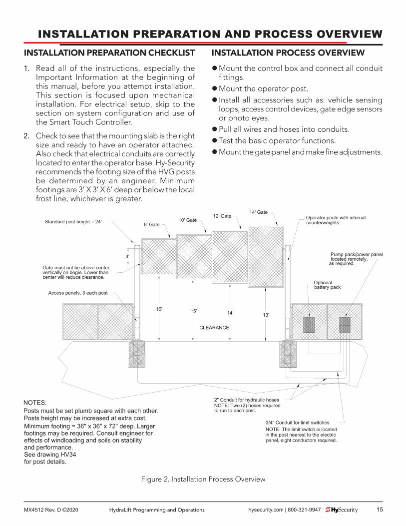
INSTALLATION PREPARATION AND PROCESS OVERVIEWINSTALLATION PREPARATION CHECKLIST
1. Read all of the instructions, especially the Important Information at the beginning of this manual, before you attempt installation. This section is focused upon mechanical installation. For electrical setup, skip to the section on system configuration and use of the Smart Touch Controller.
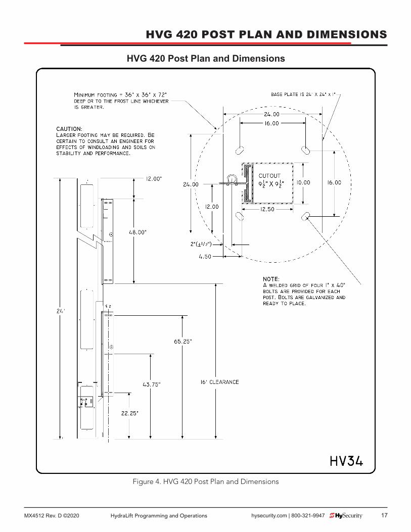
2. Check to see that the mounting slab is the right size and ready to have an operator attached. Also check that electrical conduits are correctly located to enter the operator base. Hy-Security recommends the footing size of the HVG posts be determined by an engineer. Minimum footings are 3’ X 3’ X 6’ deep or below the local frost line, whichever is greater.
INSTALLATION PROCESS OVERVIEW
zMount the control box and connect all conduit fittings. zMount the operator post. z Install all accessories such as: vehicle sensing loops, access control devices, gate edge sensors or photo eyes. zPull all wires and hoses into conduits. zTest the basic operator functions. zMount the gate panel and make fine adjustments.
Figure 2. Installation Process Overview

MX4512 Rev. D ©202016 hysecurity.com | 800-321-9947 HydraLift Programming and Operations
HVG PUMP AND ELECTRICAL PANEL
Figure 3. HVG Pump and Electrical Panel
HVG Pump and Electrical Panel
MX4512 Rev. D ©2020 HydraLift Programming and Operations hysecurity.com | 800-321-9947 17
Figure 4. HVG 420 Post Plan and Dimensions
HVG 420 Post Plan and Dimensions
HVG 420 POST PLAN AND DIMENSIONS

MX4512 Rev. D ©202018 hysecurity.com | 800-321-9947 HydraLift Programming and Operations
HVG 460 POST PLAN AND DIMENSIONS
Figure 5. HVG 460 Post Plan and Dimensions
HVG 460 Post Plan and Dimensions

MX4512 Rev. D ©2020 HydraLift Programming and Operations hysecurity.com | 800-321-9947 19
When field measuring for the necessary hose length to order, the following may be helpful:
1. There is very little room in the base of the HVG operator post and limited room in the control/power panel, therefore, your field measurements must be very accurate when calculating the length of the necessary hydraulic hoses. If your dimensions are too short, you will not reach the connections, if your measurements are too long, you will have trouble finding space for the excess hose.
NOTICEHVG operators are usually shipped without the hoses needed to complete the system. Hy-Security will make these hoses in custom lengths as required, attach the quick disconnect fittings and pre-charge the hoses with hydraulic fluid. The use of pre-charged hoses is important to avoid the introduction of air into the system.
FIELD HOSE MEASUREMENTS FOR HVG OPERATORS2. Remember that two hoses are needed for each
post. This means that you need four hoses.
3. Be sure to measure accurately the following distances: (the best way is to pull a cord through the conduit, mark it, and then measure it.)
a. The bottom of the pump/control panel to the bottom of the trench, plus 24”
b. The total distance across the trench.
c. The distance back up to the bottom of the operator, plus 6”
4. The part number for the 3/8" HVG hose is HSFHO 006 4216. Up to 100’ of hose is included in the price of the HVG operator; any additional length needed is sold by the lineal foot.
Figure 6. Installation Process Overview

MX4512 Rev. D ©202020 hysecurity.com | 800-321-9947 HydraLift Programming and Operations
INSTALLATION1. Mount control box and connect all conduit
fittings.
a. Mount control enclosure within 20’ of the nearest operator post. If installing the DC operator version, mount the battery power supply box very near the controller enclosure because of the high current demand by DC motor – For more information, see the Two Part Operator section.
b. Attach all electrical conduits as required, note diagram below and see step number 3.
2. Typical conduits required at the control enclosure
a. High voltage wires: 208 or 230 single phase or 208, 230 or 480 three phase
b. 2” conduit to each vertical lift post for the hydraulic hoses.
c. 3/4” conduit to the post with the rotary limit switch.
d. Access control wires (Keypads, telephone entry systems or any access control devices)
e. Loop wires for vehicle detectors
f. Other accessories such as warning lights etc.
3. Set the Vertical Lift posts
a. Verify that the concrete footings have cured adequately.
b. Clean threads of the mounting bolts with a wire brush to remove any concrete residue.
c. Screw a nut onto each threaded stud and turn down until there are only two or three threads remain. Lay a heavy washer on top of each nut and verify that there is about 3” of thread remaining.
d. Mount the vertical lift posts onto the foundation. Be certain that the removable access covers face into the secured side of the opening. The posts must be square with each other across the opening
e. Place another heavy washer and nut onto each threaded stud and secure loosely. verify posts are square with respect to each other and perfectly level and plumb before final tightening. Use a plumb bob or a level that is at least six foot long to verify. Use lower mounting nuts as adjusters to achieve “plumb” in both directions and twist the posts as needed to achieve “square” to the opposite post.
4. Pull and connect all necessary electrical wires and hydraulic hoses
a. HVG operators normally do not ship with hydraulic hoses included, until installer specifies exact length. See page 19 and verify correct length before ordering.
b. For protection, tape hydraulic hose(s) ends and pull through the 2" conduit from each post to controller enclosure. Connect hoses to their respective couplings, being certain to match color coded ends as described on page 24. Be certain connectors are firmly snapped together.
c. Connect electrical power wiring to On/Off switch loose wires and a grounding wire to electrical panel lower left corner. Be certain to the labeled voltage and phase of the operator matches the available supply. Also be certain to oversize the branch circuit wires to allow for voltage drop, especially for single-phase machines. See the wire size schedules in the appendix, page 72.
d. Verify primary tap of control transformer is connected to match supplied voltage. It is especially important to distinguish between 208 and 230 Volt supplies. The various voltage taps are identified by a label on the transformer.
e. Pull a minimum of four 18 gage wires, for the limit switches from control panel to junction area in the base of the operator post with the rotary limit switch. Connect to the rotary limit switch as shown on page 23. Connect these wires to the control enclosure at the five pole terminal

MX4512 Rev. D ©2020 HydraLift Programming and Operations hysecurity.com | 800-321-9947 21
5. Test and Adjust the Operator (See Smart Touch Setup First to Enable the Controls)
a. Remove the blue plastic shipping plug on the pump and replace it with the black vent cap that is provided.
b. Remove the cap screw on the release sprocket driven by the hydraulic motor in the bottom of each vertical lift post. This will allow the motors to rotate freely for basic testing.
c. Test basic functions of the operator first, before connecting any external control wiring. If your operator is equipped with vehicle detectors, be certain that they are connected to a loop or unplugged so that they do not cause interference with the function of the machine.
d. If the electric motor runs but the hydraulic motors in each post do not, close the by-pass valve located on the pump, near the base of the electric motor, or reverse any two poles of a threephase motor. Also be certain that the hose quick connectors are firmly engaged.
INSTALLATION6. Mount the gate panel to the posts
a. Place the gate panel into the opening from the outside side of the property so that the fasteners all face the secure side of the gate. Before mounting, verify that the width of the gate panel, from C/L to C/L of the end verticals, is equal to the dimension between the angle guides for the bogies, less 4-3/4” on the HVG 420 or 5-1/2” on the HVG 460. If the gate panel is too wide it will bind and interfere with the smooth operation of the gate operator and may actually cause damage to the top covers of the vertical lift posts.
b. The cap screws on the release sprocket in the bottom of each post must be removed. The bogies must be free for adjustment so that they may be centered on the gate panel's vertical edges. Mount the gate panel to the bogies while being sure that no tension is applied that may cause a binding action during travel. Replace the cap screws in the sprockets. Be sure that they penetrate through the hole in the sprocket and that the heads are fully seated.
c. Install the 1/8” auto level cables using the supplied cable. Slip the ends with the loops into the upper eyebolts. Run cables under the sheaves, across the face of the gate panel, over the opposite sheaves and to the bottom eyebolts. Pull snug and secure with clamps, then tension by adjusting the lower eyebolts. The cables should not hang loose, but the compression spring at the upper eyebolt should not be collapsed either. Cut off excess cable.

MX4512 Rev. D ©202022 hysecurity.com | 800-321-9947 HydraLift Programming and Operations
INSTALLATION7. Install the required counterweights
a. Remove the middle access cover located 4’ above the ground and fully open the gate. *(See note at end of section) Load the counter weights into the weight cage, which should now be visible through the access area. The counter weight for each post should be equal to one half of the total weight of the entire gate panel. Sheared steel plate makes an easy to handle counterweight material. For the HVG 420, use 7" x 7" x ¾” plate, which weighs about 10.4 pounds each. For the HVG 460, use 10” x 10” x ½” material, which weighs about 14 pounds each. Sheared Universal Mill plate is easy to obtain at any steel supplier. The exact amount of weight to achieve balance is easily determined when the pressure to open and close the gate is identical. Adding extra counterweight so that the open pressure is about 200 PSI less than the close pressure, may be a good idea to make an easy manual operation.
b. Operate the system a few times to verify that everything is working properly. Set the open and close limit stop positions as required. Set the brake valves. After testing the basic functions, add accessories and external control wiring. Fully test the operator functions again.
8. NOTICESince there is no counter balance for the initial operation, it may be necessary to assist the gate in opening. If necessary, use a forklift, block and tackle or manpower for this operation. If the hydraulic pump runs and the gate does not move during this operation, no harm is done. However be necessary to shunt the inherent sensor input with a jumper wire for this initial setup.

MX4512 Rev. D ©2020 HydraLift Programming and Operations hysecurity.com | 800-321-9947 23
INSTALLATIONLIMIT SWITCH SETTING/WIRING
1. For all HVG operators, four conductors minimum are required from the limit switch to the control panel.
2. Connect a pair of wires from the normally closed A side of each switch to the terminal strip in the control box marked for the limit connections. The normally open B side of the switch is unused unless the customer requires a special function.
3. The limit switch is pre-set at the factory, to limit full travel in both directions. Fine tuning may be required in the field, to suit conditions.
4. To adjust the limits:
a. Loosen the cam clamp screws.
b. Depress the pinion gear, near the switch, engaging the gear teeth.
c. Rotate the cam to trip the limit switch, several inches before full gate travel, to allow the gate to decelerate.
d. Tighten clamp screws.
e. Repeat steps “a” and “d”, for each limit switch.
Figure 7. Limit Switch Setting/Wiring

MX4512 Rev. D ©202024 hysecurity.com | 800-321-9947 HydraLift Programming and Operations
INSTALLATIONHOSE CONNECTIONS
1. Pull short hoses through the conduit into bottom of nearest HVG post, make certain that the gold and red ends will be at the post, and the red and silver ends will be at pump enclosure.
2. Pull longest hoses through the conduit into bottom of farthest HVG post, make certain that the gold and red ends at the post, and the gold and silver ends at pump enclosure.
3. At posts, mate red plugs to red sockets and gold to gold. At pump enclosure, mate in the same manner matching colors. Plug gold into gold and red to red onto the pump and splice the two silver ends together with the connector that is supplied.
Figure 8. Hose Connection Diagram

MX4512 Rev. D ©2020 HydraLift Programming and Operations hysecurity.com | 800-321-9947 25
MANUAL OPERATION
To manually lift the gate in the event of a power failure, you must pull and twist the hydraulic bypass valve that is located on the hydraulic pump right where the hoses connect. This will allow the hydraulic motors in each post to unlock so the gate panel can now be manually lifted.
Depending upon how well the gate was counterweighted, the gate may be easy to lift or fairly difficult. Review the counter weight installation instructions on page 22. In some scenarios, a forklift may be required to lift the gate until sufficient counterweight has been installed.
OPERATIONSAn alternate means of unlocking the system for manual operation that allows easier lifting of the gate can be accomplished by removing the socked head screws from the special release sprockets on each hydraulic motor. To access the release sprockets, remove the lowest access covers on each post and use an Allen wrench to remove the screws in the face of the sprocket at the end of the motor shaft.
Tie a rope onto the bottom of the gate to make it easy to pull downward.

MX4512 Rev. D ©202026 hysecurity.com | 800-321-9947 HydraLift Programming and Operations
MECHANICAL AND HYDRAULIC ADJUSTMENTS1. Brake Valves
Proper adjustment of the brake valves is important for smooth operation of the gate. In order for the brake valves to have time to function, the limit switch must trigger at least nine inches before the point at when you want the gate to stop. Adjustment of the brake valves, one for each direction of travel, will determine how quickly the gate actually stops. If adjustment is needed, loosen the 9/16” lock nut on the top of the brake valve and turn the adjustment stem, in about ¼ turn increments, with an Allen wrench. The adjustment works opposite of typical, such that a counter-clockwise adjustment will stop the gate more rapidly. If the adjustment is set too loose, the gate will bang into its physical stops. If the adjustment is set too tight, the system pressure will increase, the gate speed may decrease and the gate will jerk to a stop. Set the brake valve to achieve a controlled smooth stop, and then retighten the locking nut to hold the setting.
2. Pressure Relief Valve
This valve, which governs the maximum system hydraulic pressure available, is located on the backside of the pump, just above the limit switch. Installers are encouraged to reduce the relief valve setting to the lowest pressure that will reliably operate the gate. A lower setting reduces the maximum force that the gate operator can exert and saves energy. If adjustment is needed, loosen the 9/16” lock nut and turn the adjustment stem with a wrench. Lower pressure (force) is achieved by turning the adjuster stem counter-clockwise. The only way to display the actual relief valve setting is to unplug the hydraulic hoses from the quick disconnect fittings. Be certain to retighten the locking nut to hold the desired setting and reconnect the hoses correctly. Also see the drawing on page 66 for the location and a schedule of factory pressure relief settings.
3. Directional Valve
This valve is solenoid activated. The directional valve is below the motor near the front of the pump and energizes in order to direct the hydraulic flow to open the gate. No adjustment of this valve is possible or ever needed.
4. Chain Tension
Proper tensioning of the chain is required upon installation and periodically as a maintenance item. There must be some tension so that the chain does not sag, which would likely cause it to skip on the drive sprocket, which would alter the limit switch setting. The chain must not however be over tensioned, which would lead to stretching and possible failure. Chain tension adjustment is made at the threaded rod attachment at the bottom of the weight cage, which is accessible when the gate is fully open.
5. Auto Level Cable Tension
The 1/8” auto level cables keep the gate from “keystoning” throughout its travel. The cable tension must always be light or the cable will fray. A threaded eye bolt adjuster is provided at the bottom of each post and a spring at the top of the post is provided to assure constant tension. Adjust the cable tension for each side so that the gate is visibly level when viewed from a distance. When complete the springs at the top of the post must only be slightly compressed.STC Basics

MX4512 Rev. D ©2020 HydraLift Programming and Operations hysecurity.com | 800-321-9947 27
SMART TOUCH CONTROLLERRead this page if you are unfamiliar with using the Smart Touch Controller.
You must learn to navigate and change menu settings within the Smart Touch Controller before an installation can be completed or any control settings or function changes can be made.
Until a new operator has been congured, the controls are not functional and the display is locked in the menu mode until the User Class 1-4, has been selected. See the next page for instructions on how make this setting.
1. There are ve buttons on the membrane switch pad that provide control of everything. The Open, Close and Stop buttons serve as a three-button control station, but in the Menu Mode, they become Previous, Next and Select buttons. The Program Menu button is used to both enter and exit the Menu Mode. The Reset button clears all Errors or Faults that may occur and returns the control to its normal functioning state.
2. When in a Menu Mode, changes to be made to a Menu setting are accomplished by pressing the Previous, Next and Select buttons in the following sequence:
a. Press the Next button to move forward through the list of menu items that are available, as shown on page 32 - page 35, or press the Previous button to move back to an item that you recently passed.
b. Press the Select button if you wish to make a setting change to a menu item. The menu item will ash to indicate that its setting is ready to be changed.
c. Press Next to move forward or Previous to go back to an earlier setting choice.
d. When you have located the setting that you want to use, press the Select button and the program will accept the change and stop blinking.
e. The Program Menu button does not allow
an exit to Run Mode while a selection is still blinking. Press the Select button to stop the blinking, then you may exit to Run Mode.
f. Pressing the Next or Previous buttons when the menu item is not blinking will move to the next or previous menu item.
g. When done, press Program Menu to exit to the Run Mode.
3. Once congured, the operator will be in the Run Mode. From the Run Mode, to gain access the User Menu or the Installer Menu, follow these steps:
a. Note that the Program Menu button will not function unless the gate is at rest and no open or close inputs are active. Verify system status by pressing the LED button to disclose any active inputs. There also must not be any Alerts, Faults or Errors. Press the Reset button to clear the system if necessary.
b. Press the Program Menu button and watch the LCD scroll the system data, or press the Program Menu key a 2nd time to skip the scroll. The scrolled data displays the information in the table on page 32.
c. The LCD display scroll will stop at the menu item for the auto close timer setting [Ct __]. This is the first item in the User Menu.
d. To access the more detailed Installer Menu, the system must first be in the User Menu, and then simultaneously press the Reset button and the Open button. The LCD will change to display the UL usage class menu item [uC __] This is the first item in the Installer Menu.
4. Pressing the Program Menu button when the User or Installer Menu is not blinking will return the system to the Run Mode.

MX4512 Rev. D ©202028 hysecurity.com | 800-321-9947 HydraLift Programming and Operations
SMART TOUCH CONTROLLERSTC INSTALLATION CONFIGURATION
1. The hydraulic hoses must be connected to the quick couplers by matching the color coded ends to configure the correct directional control of the gate. If the hoses are connected incorrectly, the gate will run backwards (close when open button is activated) and this may trigger an error [Err 1] on the LCD display. (The Reset button must be pushed if this happens).
2. Turn on the power switch and observe that the LCD will first show the software version, and then stop at a steady display within two seconds. If the display reads [uC 0] go to step 3. If the operator has previously been configured, the Installer Menu must be accessed in order to reach the system configuration menu items: see step 3d at the top of this page.
3. When turning on the power for a new machine, the LCD display directly enters the Installer Menu at the [uC __] menu item, which is for selecting the user class as defined by UL. Select [uC 1] - [uC 2] - [uC 3] or [uC 4] depending upon the use application.
4. Once the usage class is set, you should exit the Installer Menu, by pressing the Program Menu button. The LCD display jumps to the close timer [Ct__] setting in the User menu, which may now be set. Either press the Program Menu button again to exit to normal run mode or set the close timer by the same programming sequence described at the previous page.
5. Note that the Installer menu cannot be exited by any means until the selection for the UL usage class [uC __] has been entered.
Test for normal function of the gate operator by running it both open and closed from the pushbuttons on the membrane switch pad. It is best to verify normal function before the gate panel has been mounted.

MX4512 Rev. D ©2020 HydraLift Programming and Operations hysecurity.com | 800-321-9947 29
STC WIRING CONTROL INPUTS
1. Test the basic open and close operator function before wiring the external control inputs. This makes it easier to troubleshoot if an unexpected function issue arises.
2. Each input has an LED to indicate when that input is active. To disclose the input status, the LED tact button must be pushed. This button is in corner near the Stop input.
3. All the control device inputs listed below are shown as a single wire input because the other wire is connected the Common Terminal Buss on the Power Supply board. The Emergency Close and Fire Dept. Open inputs are an exception and require a +24 Volt input in order to be activated. The +24 is available at the spade terminals next to the Common Buss.
SMART TOUCH CONTROLLER INPUTS
1. *Stop Push button (N.C. input, jumper to Common if unused)
2. *Open Push Button (not for radio or remote access controls)
3. *Close Push button (not for radio or remote access controls)
4. Remote Open & Radio Control (For radio / remote open device - menu opt. to also close the gate, but only when fully open)
5. Open/Close button (pushbutton or radio controls)
6. Partial Open (this input disabled on vertical lift gates)
7. Open interlock input or Time clock Open (menu configurable)
8. Free Exit vehicle detector
9. Disable Free Exit vehicle detector
10. Inside Obstruction vehicle detector (Inside reversing loop)
11. Outside Obstruction vehicle detector (Outside reversing loop)
SMART TOUCH CONTROLLER12. Shadow vehicle detector (Shadow is for Swing
gates only)
13. Edge Sensor (from sensing edge on the bottom of the gate)
14. Photo eye Common Power (supply for PE power & PE Com)
15. Photo eye Common Power (supply for PE power & PE Com)
16. Not available (N/A)
17. Photo eye Open direction (not used in HVG Vertical Lift Operators)
18. Not available (N/A)
19. Photo eye Close direction (beam spans the roadway)
20. Not available (N/A)
21. Charger AC power loss (only used in battery type operators)
22. Spare Input (unused – may have function in custom applications)
23. *Emergency Close (must menu enable and input +24 Volts to trigger) Overrides photo eyes, gate edge & vehicle detectors.
24. *Fire Dept. Open (must menu enable and input +24 Volts to trigger) Overrides photo eyes & gate edge.
WARNING* Do not connect an external control to terminals #1, 2 or 3, unless the controls are located such that there is a clear view of the entire gate area. For controls not within sight, use input terminals #4, 5 or 7.
WARNING*The Emergency Close and Fire Dept. Open inputs are to be used only if access to these controls are guarded in sufficient manner such that there is always supervision when activated.

MX4512 Rev. D ©202030 hysecurity.com | 800-321-9947 HydraLift Programming and Operations
SMART TOUCH CONTROLLER
Figure 9. STC Integrated Circuit BoardConnecting a Primary/Secondary Pair
MX4512 Rev. D ©2020 HydraLift Programming and Operations hysecurity.com | 800-321-9947 31
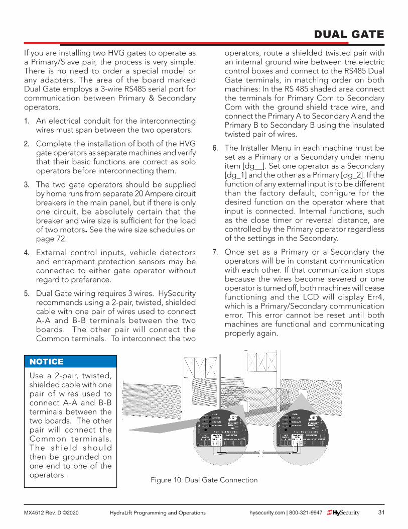
DUAL GATEIf you are installing two HVG gates to operate as a Primary/Slave pair, the process is very simple. There is no need to order a special model or any adapters. The area of the board marked Dual Gate employs a 3-wire RS485 serial port for communication between Primary & Secondary operators.
1. An electrical conduit for the interconnecting wires must span between the two operators.
2. Complete the installation of both of the HVG gate operators as separate machines and verify that their basic functions are correct as solo operators before interconnecting them.
3. The two gate operators should be supplied by home runs from separate 20 Ampere circuit breakers in the main panel, but if there is only one circuit, be absolutely certain that the breaker and wire size is sufficient for the load of two motors. See the wire size schedules on page 72.
4. External control inputs, vehicle detectors and entrapment protection sensors may be connected to either gate operator without regard to preference.
5. Dual Gate wiring requires 3 wires. HySecurity recommends using a 2-pair, twisted, shielded cable with one pair of wires used to connect A-A and B-B terminals between the two boards. The other pair will connect the Common terminals. To interconnect the two
operators, route a shielded twisted pair with an internal ground wire between the electric control boxes and connect to the RS485 Dual Gate terminals, in matching order on both machines: In the RS 485 shaded area connect the terminals for Primary Com to Secondary Com with the ground shield trace wire, and connect the Primary A to Secondary A and the Primary B to Secondary B using the insulated twisted pair of wires.
6. The Installer Menu in each machine must be set as a Primary or a Secondary under menu item [dg__]. Set one operator as a Secondary [dg_1] and the other as a Primary [dg_2]. If the function of any external input is to be different than the factory default, configure for the desired function on the operator where that input is connected. Internal functions, such as the close timer or reversal distance, are controlled by the Primary operator regardless of the settings in the Secondary.
7. Once set as a Primary or a Secondary the operators will be in constant communication with each other. If that communication stops because the wires become severed or one operator is turned off, both machines will cease functioning and the LCD will display Err4, which is a Primary/Secondary communication error. This error cannot be reset until both machines are functional and communicating properly again.
Figure 10. Dual Gate Connection
NOTICEUse a 2-pair, twisted, shielded cable with one pair of wires used to connect A-A and B-B terminals between the two boards. The other pair will connect the Common terminals. The sh ie ld shou ld then be grounded on one end to one of the operators.

MX4512 Rev. D ©202032 hysecurity.com | 800-321-9947 HydraLift Programming and Operations
STC CONTROLLER USER MENU INITIAL POWER UP
When power is turned on, the display will disclose the software revision:
Display Revision Number 2s delay Displays software version Number, ex. [h3.02]
System Data and Accessing the User Menu Settings:
If the gate is stopped in normal mode, pressing of the Menu button accesses the User Menu. After the menu button is pressed, the LCD will scroll the system data in the table below. The scrolling display stops at the close timer setting, which is the beginning of the User Menu. To exit the Menu Mode, the display must not be blinking, then simply pressing the Menu button will return the display to the Run Mode and re-enable the controls. The menu mode will also automatically return to the Run Mode if there is no activity for two minutes.
Data Displayed in Scroll Time DescriptionS1 [SLAu] or [LEAd] 2s SECONDARY Operator or LEAD Operator (PRIMARY)S2 [ot 3] Gate type (1-5) 2s Operator type: 1=HSG, 2=HRG, 3=HVG, 4=HTGS3 [uC _] UL usage class (1-4) 2s Installer setting of usage class: type 1-4S4 [d___] 24VDC Buss Voltage 2s Actual VDC buss voltageS5 [CC__] Life cycle counter 2s High digits of 6 digit life cycle counterS6 [____] Life cycle counter 2s Last 4 digits of 6 digit life cycle counter

MX4512 Rev. D ©2020 HydraLift Programming and Operations hysecurity.com | 800-321-9947 33
Read through the options available in the User Menu and the Installer Menu on the next page and you can see that the functions of this gate operator can be configured to suit most any specific need. Once you have learned to navigate the menus, as described in #2 on page 27 and how to change a menu setting, the full range of features and choices of the Smart Touch Controller are available to use. The User Menu contains the basic configuration items and the Installer Menu contains the more advanced menu items.
User Menu Options Default DescriptionU1 [Ct 0] Close timer setting 0 0 = Close timer off or 1 – 99 secondsU2 [hC 0] Momentary Close 0 0 = momentary, 1= Constant hold PB
requiredU3 [ho 0] Momentary Open 0 0 = momentary, 1= Constant hold PB
requiredU4 [AP 0] AC Power loss function 0 0 – 3 (0 =Type A, 1 = B, 2 = C, 3 = D) See
page 52U5 [ro 0] Radio control option 0 0 = Open only, 1 = Adds close ability when
full openU6 [bF 2] Warn before operate 2 0 =off, 1 = Buzzer alerts 3 seconds before
+ in motion, 2 = Buzzer alerts 3 sec before + 2 seconds in motion
U7 [FA 0] Forced open Alert and automatic gate reposition
0 0 = off, 1 sound buzzer (2 pulses/sec) if forced open for more than four seconds, time out in 30 Sec
U8 [dA 0] Drift Closed Alert and automatic gate reposition
0 0 = off, 1 sound buzzer (2 pulses/sec) if drift closed and cannot reopen within four seconds.
U9 [PE 0] Photo Eye Align Mode 0 0= off, 1 = on (auto off when close limit triggered)
U10 [CL 0] Clock set (24 hour type) 0 0= display, 1= set mins, 2= set hours, 3= day, 4= month
U11 [Ld 5] LCD Contrast set 5 1 - 9 = Adjusts contrast of the display
These Notes Refer to the Menu Above:
S1 Appears only if the operator is configured as a master or a slave unitU1 Close timer setting does not appear when set for constant contact close to functionU4 Power loss function only appears if factory has provided DC type operatorU6 We strongly advise never disabling the Warn Before Operate buzzer.
STC CONTROLLER USER MENU

MX4512 Rev. D ©202034 hysecurity.com | 800-321-9947 HydraLift Programming and Operations
STC CONTROLLER INSTALLER MENU The Installer Menu can be accessed only by entering the User Menu first, and then by pressing the Reset button and the Open button simultaneously. To restore the factory default settings, go to menu item [Fd_0] and change the setting to 1, then press the Program Menu button. The entire menu will reset to the factory defaults.
Installer Menu Options Default DescriptionI1 [uC 0] Set UL Usage Class 0 0 = Gate disabled, Set Class 1 through 4
useI2 [Fd 0] Load Factory Defaults 0 0 = User settings, 1 = Load defaults (resets
full menu)I3 [dg 0] Set Primary/Secondary type 0 0 = Solo operator, 1 = Secondary unit, 2 =
Primary unitI4 [Ch 0] Set AC Charger or Solar 0 0 = DC + AC charger, 1 = DC + Solar
chargerI5 [Fo 0] Enable Fire Dept. Open 0 0 = input disabled, 1 = enabledI6 [oC 0] Enable Emergency close 0 0 = input disabled, 1 = enabledI7 [SE 3] Inherent Sensor sens. 3 1 = Maximum sensitivity, 9 = Lowest
sensitivityI8 [SS 0] Inherent Sensor function 0 1 = stop only (note, functions in usage
class 4 only)I9 [LC 0] Leaf delay Close 0 0 = none (1-7) ½ second steps (Primary/
Secondary only)I10 [Lo 0] Leaf delay Open 0 = none (1-7) ½ second steps (Primary/
Secondary only)I11 [rt 0] Maximum run timer 0 0 = 60 Seconds max run, 1 = 300 Seconds
max runI12 [EC 0] PEC reverse to open 0 0 = Close eye stops only, 1 = 2 sec reverse
to openI13 [PC 0] Set PEO/ PEC – NO/NC 0 0 = Normally Open PE output, 1 = N.C.
(Supervised)I14 [gC 0] Set Edge input – NO/NC 0 0 = Normally Open Edge output, 1 =
Normally ClosedI15 [tC 1] Time clock/ Interlock input 1 0 = select Time Clock, 1 = select Open
InterlockI16 [or 1] OOLD detector function 1 0 = pause closing only, 1 = enable
reversing to openI17 [ir 1] IOLD detector function 1 0 = pause closing only, 1 = enable
reversing to openI18 [dL 1] Vehicle detector logic 1 1 = std, 2 & 3= fast close timer, 4 = full anti-
tailgate*I19 [r1 0] User relay 1 option 1 0 = disabled, 1 – 19 = see relay output
options page 28

MX4512 Rev. D ©2020 HydraLift Programming and Operations hysecurity.com | 800-321-9947 35
Installer Menu Options Default DescriptionI20 [r2 0] User relay 2 option 6 0 = disabled, 1 – 19 = see relay output
options page 28I21 [r3 0] User relay 3 option 1 0 = disabled, 1 – 19 = see relay output
options page 28I22 tL 0] Gate Open alert 2 0 = 0 sec, 1= 15s, 2= 45s, 3= 75s, 4= 105s,
5= 135sI23 [Lt 0] Loitering alert 3 0 = 0 sec, 1= 15s, 2= 45s, 3= 75s, 4= 105s,
5= 135sI24 [ELd0] Test factory ELD* 0 0=Run, 1=show freq, 2=show call level 0-7,
3=set freq 1-4I25 [iLd0] Test factory IOLD* 0 0=Run, 1=show freq, 2=show call level 0-7,
3=set freq 1-4I26 [oLd0] Test factory OOLD* 0 0=Run, 1=show freq, 2=show call level 0-7,
3=set freq 1-4I27 [SLd0] Test factory SLD* 0 0=Run, 1=show freq, 2=show call level 0-7,
3=set freq 1-4
These Notes Refer to the Menu Above:
I1 This setting must be configured or the gate cannot function and menu will not exit.I4 This setting appear only if the factory has provided a DC powered gate operatorI8 IES stop only setting [SS __] does not appear unless set as a class 4 operatorI9-10 These settings appear only if the Installer Menu is set for Primary / Secondary functionI22-23 These settings appear only if the Installer Menu has set relays r1-r3 for these alerts
NOTICESee page 55 for description of vehicle detector & Loop Fault diagnostics
STC CONTROLLER INSTALLER MENU

MX4512 Rev. D ©202036 hysecurity.com | 800-321-9947 HydraLift Programming and Operations
USER MENU FUNCTION DESCRIPTIONS User 1 [Ct _] Close timer setting: This menu item is the automatic close timer for the gate. The factory setting is zero, which is off. It may be configured up to 99 seconds.
User 2 [hC 0] Momentary Close: This menu item is to configure for the system for constant hold push button Close function. The factory setting is zero, which is momentary contact input.
User 3 [ho 0] Momentary Open: This menu item is to configure for the system for constant hold push button Open function. The factory setting is zero, which is momentary contact input.
User 4 [AP 0] Power loss function: This menu item only appears if the operator is a DC battery powered version. This item is to configure what gate function will occur when the AC power fails. See page 52 for more detailed information on DC operators.
User 5 [ro 0] Radio control option: This menu item is to configure whether a radio input can open only (default) or if set to 1, also has the ability to close the gate when it is fully open.
User 6 [bF 2] Warn before operate: This menu item controls the warn before operate buzzer and can be configured three ways. Setting the menu item to zero turns the buzzer off, but we strongly advise leaving this valuable warning feature active to alert prior to gate motion. Never cut the wires to the buzzer or unplug it. Set to 1 and the buzzer will sound three seconds before motion and the entire time during gate motion. Set to 2 (default) and the buzzer will sound three seconds before motion and for the first two seconds of motion.
User 7 [FA 0] Forced open Alert and automatic gate reposition: This function is intended for highly secure facilities. If it is enabled, by setting the selection to 1, it will reinitiate a closure if a gate is somehow forced to open far enough that the close limit switch releases. The Alert buzzer will sound immediately, even if it had been turned off, and the motor will restart to secure the gate fully closed. If the gate is not fully closed within four seconds the motor turns off and the alert buzzer sounds an intruderalert for thirty seconds. The LCD display reads ALE1.
User 8 [dA 0] Drift Closed Alert and automatic gate reposition: If it is enabled, by setting the selection to 1, it will restore a gate to back its fully open position if it drifts closed for any reason. The buzzer will sound a warn before operate alert, even if it had been turned off, and the motor will restart to reopen the gate. The motor will run for a maximum of four seconds and if the gate is not fully open in this period, the buzzer sounds for ten seconds and the LCD display reads ALE2.
User 9 [PE 0] PE Alignment Mode: This feature may be activated as an aide to photo-eye emitter / receiver alignment. The buzzer chirps once as the photo eye is triggered or twice when the photo eye is released. The Alignment Mode is cancelled with any close limit input or reset input.
User 10 [CL 0] Clock and date set: The Smart Touch Controller is equipped with a 24 hour 365 day clock, so that events of significance can be logged and stamped with the time and date. This feature is useful to record historical operation data, which can be accessed via the RS232 port. To set or adjust the hour, minute, day or month, see page 31.
User 11 [Ld 5] LCD Contrast set: Under some extreme high or low temperature conditions, it may be necessary to adjust the contrast of the LCD display. The display is adjustable from 0-9 with a factory default setting of 5.Installer 1 [uC 0] Set UL Usage Class: This menu item is used to set the UL usage class, which must be set by the installer before the operator will function. See "STC Installation Configuration" on page 28, step 3.

MX4512 Rev. D ©2020 HydraLift Programming and Operations hysecurity.com | 800-321-9947 37
INSTALLER MENU FUNCTION DESCRIPTIONS Installer 2 [Fd 0] Load Factory Defaults: This menu item is used to globally restore all menu settings back to new machine status. To activate, change the setting 0 to 1 and push the Menu button. The UL usage class and the hand configuration will need to be set again.
Installer 3 [dg 0] Set Solo, Primary or Secondary type: This menu item is used to configure an operator as a Primary or a Scondaryoperator in Primary/Secondary paired gate installations.
Installer 4 [Ch 0] Set AC Charger or Solar: This menu item appears on 24 VDC battery machines only and is set to solar only when there is no AC battery charger.
Installer 5 [Fo 0] Enable Fire Dept. Open: This menu item is used to enable the Fire Dept. Open input. When set to [Fo_1] this input will override vehicle detectors, photo eyes and gate edges to open a gate. A reset is required before the gate can be closed.
Installer 6 [oC 0] Enable Emergency Close: This menu item is used to enable the Emergency Close input. When set to [oC_1] this input will override vehicle detectors, photo eyes and gate edges to close a gate. A reset is required before the gate can be opened.
Installer 7 [SE 6] Inherent Sensor sensitivity: This menu item is to adjust the sensitivity of the internal inherent sensor. Available settings are 1-9, with 9 being the least sensitive.
Installer 8 [SS 0] Inherent Sensor function: This menu item is only available in UL class 4 operators and allows an option whereby the inherent sensor will only stop the gate.
Installer 9 [LC 0] Leaf delay Close: This menu item only appears if the operator is set up as a Primary or a Secondary. Available settings are 1-7. Each increment adds ½ second, to a maximum of 3 ½ seconds time delay, before the operator activates when commanded to close.
Installer 10 [Lo 0] Leaf delay Open: This menu item only appears if the operator is set up as a Primary or a Secondary. Available settings are 1-7. Each increment adds ½ second, to a maximum of 3 ½ seconds time delay, before the operator activates when commanded to open.
Installer 11 [rt 0] Maximum run timer: The maximum run timer has a default setting of 60 seconds. This menu item allows an optional setting of 300 seconds, if changed to [rt_1].
Installer 12 [EC 0] PEC (photo eye close) reverse to open: The default for this menu item is for non-reversal if the close photo eye is triggered. The optional setting of [EC_1] will cause the gate to reverse to open for two seconds if triggered while closing.
Installer 13 [PC 0] Set PEO/ PEC – NO/NC: The default for this menu item is for photo eyes with Normally Open outputs. The optional setting of [PC_1] will require a Normally Closed output. If set for N.C. the connection is also supervised and any open or short circuit fault will generate a FAL2 alert, which requires a Stop button reset to re-enable any function if triggered.
Installer 14 [gC 0] Set Edge input – NO/NC: The default for this menu item is for edge sensor with Normally Open outputs. The optional setting of [gC_1] will require a N.C. output.
Installer 15 [tC 1] Time clock / Interlock input: This menu item configures the input at terminal #7 to be either for the gate interlock function, or for an external time clock to open input. The default setting is [tC_1] for the interlock function.

MX4512 Rev. D ©202038 hysecurity.com | 800-321-9947 HydraLift Programming and Operations
INSTALLER MENU FUNCTION DESCRIPTIONS Installer 16 [or 1] OOLD (Outside Obstruction loop detector) function: The default for this menu item is for full reversal when the OOLD is triggered. The optional setting [or_0] causes the gate to only pause when triggered. Closure begins as soon as the loop is clear again.
Installer 17 [ir 1] IOLD (Inside Obstruction loop detector) function: TThe default for this menu item is for full reversal when the IOLD is triggered. The optional setting [ir_0] causes the gate to only pause when triggered. Closure begins as soon as the loop is clear again.
Installer 18 [dL 1] Vehicle detector logic: This menu item is used to configure quick close logic. For vertical lift gates, there are four modes. See the full description on page 57.
Installer 19, 20, 21 [r1 0], [r2 0], [r3 0] User output relay 1 - 3 programming options: These three menu items are used to configure the function of the three user output relays. There are 19 optional choices, which are described in detail on page 28.
Installer 22 [t L 0] Gate Open alert: This menu item is to adjust the time delay before activating the user relay function #8, described on page 40. Time settings up to 135 seconds.
Installer 23 [Lt 0] Loitering alert: This menu item is to adjust the time delay before activating the user relay function #13, described on page 40. Time settings up to 135 seconds.
Installer 24 [ELd0] Factory ELD: Controls the Hy5B Free Exit detector, see page 55
Installer 25 [iLd0] Factory IOLD: Controls the Hy5B IOLD detector, see page 55.
Installer 26 [oLd0] Factory OOLD: Controls the Hy5B OOLD detector, see page 55.
Installer 27 [SLd0] Factory SLD: Controls the Hy5A Shadow detector, see page 55.

MX4512 Rev. D ©2020 HydraLift Programming and Operations hysecurity.com | 800-321-9947 39
CORRECTIONAL FACILITY - USER OPTIONAL WIRINGA special terminal strip has been pre-wired in Correctional facilities models to the three user relay outputs for easy field wiring of the common interconnect options. If alternate output functions are required, see page 28, titled Options for User Programmable Output Relays 1-3.
Connecting an Interlocked Pair:
An interlocked pair of operators is not a Primary/Secondary system, but is simply two gate operators interlocked such that the one cannot open unless the other is fully closed. This connection is used frequently at correctional facilities for Sally Port gates. The Smart Touch Controller provides both an interlock input (#7) and the interlock output contact that is required.
1. User relay 1 on the Smart Touch Board has been set by the factory to provide the necessary interlock function. Connect a total of four wires between operator #1 and operator #2 as follows: One wire to the Common buss of each operator to the User 1 relay COM terminal of the other operator. Then, connect wires from the User 1 relay NC terminal to the Interlock input (#7) of the other operator.
2. If User relay 1 has already been used for a different function, then one of the other relays User 2 or User 3 must be wired as described above and set to output function 1. The user relays are configured in the Installer Menu as item [r1__], [r2__] or [r3__] according to the definitions described on page 40.
3. The interlock input, terminal #7, is convertible to alternately be a time clock input, so it is possible that it may need to be switched back for the interlock function. If this alteration is needed, go to the Installer Menu, and set item [tC _] to be [tC_1].
Connecting to an External Lock Mechanism:
An external solenoid lock or maglock can be controlled by the Smart Touch Controller to unlock just before gate motion begins.
1. User relay 2 has been set by the factory to provide the necessary output for a solenoid lock. Connect the voltage matching the lock solenoid to User 2 COM and connect a solenoid coil to User 2 NO (connect a maglock coil to User 2 NC). The un-switched solenoid or maglock wire connects directly to its supply voltage common conductor.
2. If User relay 2 has already been used for a different function, then one of the other relays User 1 or User 3 must be wired as described above and set to output function 6. The user relays are configured in the Installer Menu as item [r1__], [r2__] or [r3__] according to the definitions described on page 28.
Connecting the Gate Secure Position Indicator Output:
An external device can be signaled by the Smart Touch Controller to indicate the gate is secure.
1. User relay 3 has been set by the factory to provide the necessary output for position indication. Connect the voltage matching the indicator light to User 3 COM and connect the gate secure light to User 3 NC. The other indicator light wire connects directly to the voltage common conductor. If an unsecured light is required, connect it to User 3 NO.
2. If User relay 3 has already been used for a different function, then one of the other relays User 1 or User 2 must be wired as described above and set to output function 1. The user relays are configured in the Installer Menu as item [r1__], [r2__] or [r3__] according to the definitions described on page 40.

MX4512 Rev. D ©202040 hysecurity.com | 800-321-9947 HydraLift Programming and Operations
USER PROGRAMMABLE OUTPUT RELAYS 1-3 OPTIONSThe Smart Touch Controller can be set to interface to many types of external devices through the use of its programmable output relays. All of the output functions listed below are accessible in the Installer Menu under the selection [r1 __], [r2 __] and [r3 __]. Select which relay you wish to use and enter the appropriate function by the numbers as listed below.
1. Close Limit output: This output can also be used to create an interlock signal to another operators interlock input, or simply to indicate that the gate is secure. The relay is released at full closure.
2. Close limit pulse output: This output may be used in a sequenced system to command a 2nd machine to close. Generates a brief pulsed output that occurs when the close limit is triggered.
3. Open limit output: This output is used to indicate a full open position indication. This output becomes active when to open limit is triggered and releases when the open limit is released.
4. Open limit pulse output: This output may be used to trip a sequenced barrier arm gate operator to open. Generates a brief pulsed output occurs when the open limit is triggered. An additional pulse is also generated with any new open command even when the gate is already fully open.
5. Warn before/during operate output: This output may be used to control an external warning device. This output will operate at the same time as the internal warn before operate buzzer.
6. Gate Lock output: This output may be used to control external solenoid locks or magnetic locks. In both directions of travel, this output will be activated about 7/10th of a second before the operator starts moving the gate, and remains active while moving and for a few seconds after stopping.
7. Gate forced open output: Alarms if the gate is forced off the closed limit switch, and operator is not able to restore the gate to full closed within four seconds. This alarm resets itself in 30 seconds.
8. Gate open too long output: Activates when the gate has been open longer than a user-selected period of time. Adjustable from 0 delay, then 15 seconds delay to 135 seconds delay in 30-second time increments.
9. Safety Mode Alert output: Activated when system is in the Safety Mode or the Entrapment Mode. Safety Mode occurs upon an impact with an obstruction. Entrapment Mode means the gate is stopped and occurs if the internal inherent sensor triggers while the system is in the Safety Mode.
10. Entrapment Mode Alert output: Activated only when system is in the Entrapment Mode.
11. Unauthorized Vehicle Entry output: Activated when a 2nd vehicle enters from the outside, without a valid input from an access control device. This output releases when an access control input signals open or the gate reaches the close limit position.
12. Outside Obstruction Vehicle Detector output: This output may be used to interlock to an entry device to prevent pedestrian use. This output is active whenever the OOLD is tripped.
13. Special output from “OOLD” only when gate is closed: Used to annunciate a vehicle or to indicate loitering. Adjustable from 0 delay, then 15 to 135 seconds delay in 30-second time intervals.
14. Gate nearing full travel output: For operators with RPM sensors only. This output is activated when the gate is three feet from full travel in both the open and close directions. This output can be used to reduce the sensitivity of a proximity sensor near the ends of gate travel.

MX4512 Rev. D ©2020 HydraLift Programming and Operations hysecurity.com | 800-321-9947 41
15. Gate Failure output: This output is activated to report that a problem has occurred. Indicates that system in an Error Mode, Fault Mode or Entrapment Mode. If active, the gate is disabled.
16. Motor Running output: This output is active when the motor is running and the gate is in motion.
17. AC Power Failure output: This relay is normally energized, but drops with loss of AC power. This output is also active on DC machines when the battery charger is off.
18. DC Power Failure output: This output is activated when the battery power is very low, but the output ceases when the battery is dead. The relay is triggered when the battery is less than 20 Volts.
19. Flasher Relay: This output is intended to control flashing lights that pulse once per second. The relay is activated all the time, except when the open limit switch is triggered.
USER PROGRAMMABLE OUTPUT RELAYS 1-3 OPTIONS

MX4512 Rev. D ©202042 hysecurity.com | 800-321-9947 HydraLift Programming and Operations
CLOCK FUNCTIONSSETTING THE TIME AND DATE
The Smart Touch Controller is equipped with a 24 hour (military time), 365 day clock, so that events of significance can be logged and stamped with both the time and the date. This feature is useful to record key historical operational data and a log of Alerts, Faults and Errors, all of which can be accessed from the RS232 port with a PC computer or a PDA using the Palm OS. Optional Hy-Security supplied software and cables are required in order to read this data.
1. To set or adjust the time or date, go the User menu item [CL_0] and then push the Select button so that [CL_0] blinks. Press the Next button to change the setting from [CL_0] to 1, 2, 3 or 4 depending upon which setting is to be altered. 1 = minutes / 2 = hours / 3 = days / 4 = months.
2. Once you have selected a blinking setting [CL 1-4], push the Select button (Note: you must push the Program Menu button for software versions prior to h3.01) to change the display to a blinking (adjustable) value. The following letters will be displayed on the left side to aid in knowing which setting is being made:
a. Setting [CL 1] = minutes – display [ni 0–59]
b. Setting [CL 2] = hours –--- display [hr 0–23]
c. Setting [CL 3] = days –---- display [dA 1-31]
d. Setting [CL 4] = months – display [no 1-12]
3. Make any required change to the hour, minute, day or month in the typical manner by using the Next or Previous buttons, then press the Select button to enter the change, just as typical for all of our other menu settings.
4. When done, you may have to restore the setting to [CL 0] because the Menu button may not function to allow the user to exit the clock setting mode until the user has changed the setting back to [CL 0], which places the clock in its normal display mode.
5. A lithium disk battery supports the clock so that the time is not lost when the main power is off
6. This battery should be replaced about every five years. Use a DL 2025 / DL 2032 or CR 2025 / 2032 battery.

MX4512 Rev. D ©2020 HydraLift Programming and Operations hysecurity.com | 800-321-9947 43
ENTRAPMENT PROTECTION DEVICE SCHEMATIC FOR VERTICAL GATES
This figure illustrates a sample plan for a gate, incorporating the elements described below.
1. Photo eyes stop the gate to help prevent vehicular or personal entrapment.
2. Obstruction loops. (located inside and outside of the gate, and eight feet apart).
3. Optional free exit loop
4. Sensing edge on the bottom of the gate sends a signal to operator to stop and reverse when an obstruction is encountered.
This schematic view is not meant to recommend the only way to set up your configuration, but to point out the various elements of a proper automatic vehicular gate installation. The gate operator itself is only one component in the total system. Always install a separate pedestrian gate.
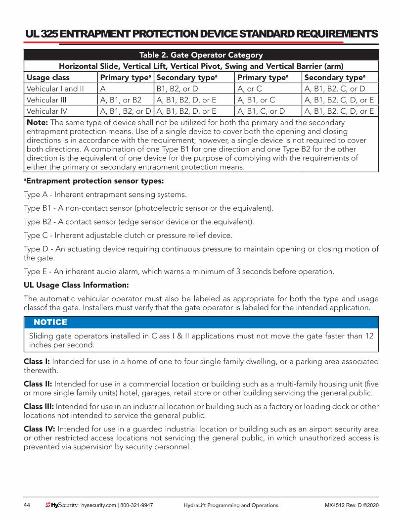
MX4512 Rev. D ©202044 hysecurity.com | 800-321-9947 HydraLift Programming and Operations
UL 325 ENTRAPMENT PROTECTION DEVICE STANDARD REQUIREMENTS
Table 2. Gate Operator CategoryHorizontal Slide, Vertical Lift, Vertical Pivot, Swing and Vertical Barrier (arm)
Usage class Primary typea Secondary typea Primary typea Secondary typea
Vehicular I and II A B1, B2, or D A, or C A, B1, B2, C, or DVehicular III A, B1, or B2 A, B1, B2, D, or E A, B1, or C A, B1, B2, C, D, or EVehicular IV A, B1, B2, or D A, B1, B2, D, or E A, B1, C, or D A, B1, B2, C, D, or ENote: The same type of device shall not be utilized for both the primary and the secondary entrapment protection means. Use of a single device to cover both the opening and closing directions is in accordance with the requirement; however, a single device is not required to cover both directions. A combination of one Type B1 for one direction and one Type B2 for the other direction is the equivalent of one device for the purpose of complying with the requirements of either the primary or secondary entrapment protection means.
aEntrapment protection sensor types:
Type A - Inherent entrapment sensing systems.
Type B1 - A non-contact sensor (photoelectric sensor or the equivalent).
Type B2 - A contact sensor (edge sensor device or the equivalent).
Type C - Inherent adjustable clutch or pressure relief device.
Type D - An actuating device requiring continuous pressure to maintain opening or closing motion of the gate.
Type E - An inherent audio alarm, which warns a minimum of 3 seconds before operation.
UL Usage Class Information:
The automatic vehicular operator must also be labeled as appropriate for both the type and usage classof the gate. Installers must verify that the gate operator is labeled for the intended application.
Class I: Intended for use in a home of one to four single family dwelling, or a parking area associated therewith.
Class II: Intended for use in a commercial location or building such as a multi-family housing unit (five or more single family units) hotel, garages, retail store or other building servicing the general public.
Class III: Intended for use in an industrial location or building such as a factory or loading dock or other locations not intended to service the general public.
Class IV: Intended for use in a guarded industrial location or building such as an airport security area or other restricted access locations not servicing the general public, in which unauthorized access is prevented via supervision by security personnel.
NOTICESliding gate operators installed in Class I & II applications must not move the gate faster than 12 inches per second.

MX4512 Rev. D ©2020 HydraLift Programming and Operations hysecurity.com | 800-321-9947 45
SECONDARY PEDESTRIAN ENTRAPMENT SENSOR PLACEMENT AND USE
Automatic gate operators are intended only for vehicular use and pedestrians must be routed to a separate man gate, however sensors are still required in order to provide a degree of protection should anyone happen to stray into the area of an automatic gate. Generally there are two types of external sensors that may be used: Contact type sensors, such as an edge sensor, and non-contact sensors, such as photoelectric eyes. Current industry standards require the use of either type or both of these sensors, as a secondary device, in Class I and Class II automatic sliding gate installations, because the general public is likely to be present. Although there are alternatives for Class III and IV installations, we highly recommend the use of external sensors for all automatic gate applications.
WARNINGTo reduce the risk of serious injury or death, read and follow all instructions in the gate operator handbook and on the warning labels.
The specifier or installer may choose either photoelectric eyes or edge sensors, or use these devices in combination, but both the open and closing directions of gate travel must be guarded. The UL 325 standard for automatic sliding gates specifically requires the following:
zOne or more non-contact sensors (photoelectric eyes) shall be located where the risk of entrapment or obstruction exists, such as the perimeter reachable by a moving gate. zOne or more contact sensors (edge sensors) shall be located at the bottom edge of a vertical lift gate. zA hardwired contact sensor shall be located and it’s wiring arranged so that the communication between the sensor and the gate is not subjected to mechanical damage. zA contact sensor that transmits its signal to the gate operator shall be located such that the signal is not impeded by building structures or other obstructions and shall function under its intended end-use conditions. zThe contact and non-contact sensors must be tested and labeled as “Recognized Components” under the UL 325 standard in order to be deemed acceptable for use in this application.
Study the entrapment protection schematic and consider your specific installation to determine where the greatest risk of entrapment exists. Locate the edge sensors and/or the photoelectric sensors accordingly. Be certain that a sufficient number of sensors are used so that both directions of gate travel are guarded.

MX4512 Rev. D ©202046 hysecurity.com | 800-321-9947 HydraLift Programming and Operations
GATE REVERSING EDGE (CONTACT TYPE) SENSOR INSTALLATION1. Follow the guidelines in the Entrapment
Protection Schematic to plan the most appropriate mounting position for the edge sensor to be installed. A requirement of the UL 325 standard is that an edge sensor be laboratory tested and “recognized” under UL 325.
2. Drill holes through the edge’s mounting channel and through the surface that each gate edge is to be mounted. Securely fasten every edge sensor.
3. Edge sensors that are not attached to the moving gate, such as post mounted sensors are wired in parallel and directly connected to the gate operator:
a. Always route the leads of the edge sensors to the gate operator so that they are protected from physical damage.
b. Connect one edge sensor lead to our common buss on the power supply board and the other to terminal #13, which is labeled Edge Sensor input.
4. Edge sensors may be used with an edge transmitter and a receiver in order to transmit to the gate operator. We do not recommend the use of retractable cord reels or curl cords because of durability problems with these devices in outdoor environments.
a. Mount the gate edge sensors to the leading edge and bottom edge of the gate so that entrapment protection is provided in both directions of travel.
b. Mount one or two edge transmitters (Linear Model #3022 or equivalent) onto the gate panel near the upper corner of the leading edge of the gate. All gate edges will function correctly if only one transmitter is used, but wiring multiple edges to a single transmitter may be impractical or displeasing visually.
c. Connect the edge(s) to the terminals in the edge transmitter and set the DIP switches of the transmitter to match the setting in the receiver to be used.
5. Mount a commercial style radio receiver* (external antenna type) on the inside of the operator, below the electrical box. Knock out the smallest hole in the lower right corner of the electrical box and route the wires to the area marked Radio Options. Only three wire connections are needed because the 24-Volt supply and the radio output share a wire. Being certain to observe polarity, crimp the black radio power wire together with one of the radio output wires into a .25” spade connector and connect to the COM terminal. Connect the red wire to the +24V terminal and connect the other radio output contact wire to the spade marked EDGE. Note that this terminal is the same as the #13 input terminal labeled Edge Sensor on the main control board.
a. Mount an external antenna onto the top of a fixed post of the fence near the operator.
b. Connect the antenna into the socket on the radio receiver.
c. Set the DIP switches in the receiver to match the same code used in the transmitter.
6. Test the operation of the reversing edge to make sure that it is functions correctly. Advise the user of the gate to be certain to retest this vital function weekly.
* If there is also to be a radio receiver for a hand held transmitter to operate the gate, be certain to use a two channel commercial receiver. Remember that the transmitter and receiver must have their codes set the same or they will not function.

MX4512 Rev. D ©2020 HydraLift Programming and Operations hysecurity.com | 800-321-9947 47
INSTALLING PHOTOELECTRIC (NON-CONTACT) SENSORSGENERAL INFORMATION:
Follow the guidelines in the Entrapment Protection Schematic to plan the most appropriate mounting positions for the photo-eye sensors to be installed. If there are no other secondary external entrapment protection sensors (typically an edge sensor), at least one photoelectric sensor is required to serve to stop the gate if an obstruction is present.
There are two common types of photoelectric sensors, through beam and retro-reflective, each has some advantages. A through beam sensor is generally more powerful and able to function reliably with dirty optics and in poor weather. A retro-reflective sensor has the convenience of not requiring the installation and electrical wiring of the remote emitter required in a through beam system, but is generally more problematic in poor weather. Avoid use of a retro-reflective device to span a distance greater than 24 feet in an outdoor environment or performance will probably be unsatisfactory.
COMPATIBILITY:
A requirement of the UL 325 standard is that a photoelectric sensor be laboratory tested and “recognized” under UL 325. In order to be compatible with a Hy-Security operator, a photo eye must be rated to function from 24 Volts DC source power.
INSTALLATION:
Mount the photo eye approximately 15” to 30” above the ground and as close to the gate as possible. Unless there are also gate edges for entrapment protection, a minimum of one photo eye will be required to function for the closing direction of travel. Mount the receiver on the post nearest the controller boxand the emitter on the far post. In some situations, an additional photo eye should be installed on thepublic side of the gate. The installation locations described above are intended for pedestrian detection, if photo eyes are also to be used for vehicular detection, consider, in addition to the low elevation photo eye for cars, another photo eye at a height of about 55” to detect semi-trucks.
CONFIGURATION:
If the photo eye has an internal switch for setting Light Operate vs. Dark Operate, select Light Operate. If the photo eye has a relay output and has both NO and NC terminals, some experimentation may be required to determine the proper connection. This is because in the Light Operate mode the output relay is normally energized and releases when the beam is blocked. Some manufacturers label an output as NO, when it is actually an NC contact. If the photo eye has a solid-state output and provides the option of a sinking or sourcing connection, choose the sinking connection.
CONNECTION:
Three wires to the receiver and two wires to the emitter are all that is required.
a. The +24 Volt source power is obtained from our power supply board.
b. The –24 Volt source power is obtained from our terminals #14 or 15, labeled (Photo Eye Power) on the Smart Touch Controller board.
Note: The –24 Volt Photo Eye Power also supplies the photo eye Common.
c. The photo eye NO or NC output connects to the Smart Touch Controller at terminal #19.
SUPERVISED CONNECTION:
If the photo eye being installed has a true NC output (one that is NC when the photo eye is powered, aligned and set for Light Operate) then a supervised connection is recommended. A supervised connection will signal a system Fault and prevent gate operation if the photo eye connection ever becomes an open circuit or a short circuit. The Installer Menu item [PC_0] must be changed to [PC_1] to enable this feature. See Installer menu 13 on page 34 and page 37.

MX4512 Rev. D ©202048 hysecurity.com | 800-321-9947 HydraLift Programming and Operations
INSTALLING PHOTOELECTRIC (NON-CONTACT) SENSORSPHOTO EYE FUNCTION:
A tripped photo eye will prevent the gate from starting in either direction if the gate is stationary. If tripped while in motion, the standard function is to pause the gate motion and then automatically restart again if the photo eye is clear within five seconds. An optional setting in the Installer Menu will cause a 2 second reversal of travel. See Installer menu 12.
ALIGNMENT:
Most photo eyes require careful optical alignment in order to aim the emitter beam to the center of the receiver or reflector. In order to avoid false triggering, it is important to carefully align the system, especially with retro-reflective photo eyes. The best way to assure true centering of the beam is with some trial testing where the emitter is shifted to move the beam left and right and up and down until the range of the invisible cone of the infrared beam is known. Photo eyes usually provide alignment aid LED’s for this setup, but they can be hard to see. Hy-Security has provided a unique feature that causes our buzzer to chirp when the photo eye enters and exits alignment. See User menu 9. Set the Installer menu item [PE_0] to [PE_1] and the buzzer will provide an audible indication both when the beam is broken and remade.
Notes about retro-reflective systems:
Correct installation and alignment of a retro-reflective photo eye and its reflector is important for a trouble free installation. Any system operating at a range greater than 16 feet is more prone to false triggering due to dirty optics, condensation or poor weather. If care is taken in the initial mounting and alignment of the 3-inch reflector, the chance of problems is greatly reduced.
Taking steps to protect the photo eye and the reflector from being exposed to fog and being absolutely certain the photo eye is perfectly aligned will greatly reduce any false triggering of the system. The ideal mounting of a retro-reflective photo eye is inside and enclosure of some sort.
The ideal mounting for the reflector is suspended inside a twelve-inch long piece of 3-inch PVC conduit. Cut the opening of the PVC conduit at a 45-degree angle to act as a drip shield. Hold the reflector against the backside of the PVC conduit by attaching a 3-inch male connector. Do not cement the connector, so that the reflector can be reached for future cleaning. To create a mounting base, attach a 3-inch aluminum flange (electric meter hub) to the connector. This whole package can be mounted to any flat surface.
Locate the reflector in the center of the invisible beam of infrared light to achieve the most sensitive alignment. The beam center is determined by the following test: while holding the reflector in your hand, slowly raise it until the beam is no longer returned, and the photo eye trips. Mark this maximum height. Now lower your hand and determine the lower limit of the infrared beam by watching for the trip point. Mark this position as well. Repeat the same procedure for left and right at the center elevation of the beam, as determined by the previous test. Once the four limits have been determined, either mount the reflector in the center of the area outlined or realign the eye for the position of the reflector. If the photo eye is realigned, be sure to perform the centering test again to verify that the reflector is truly in the center.
A last tip – if you coat the reflector with common dishwashing detergent, or some other anti-fogging compound, it will reduce fogging from atmospheric moisture.

MX4512 Rev. D ©2020 HydraLift Programming and Operations hysecurity.com | 800-321-9947 49
DETECTOR INSTALLATION GUIDEDETECTOR BASICS
The vehicle detector passes a small current flow through the “loop” which then becomes an inductive coil. When a vehicle passes over a loop the detector senses the resultant drop in the inductance, and actuates the detector output.
LOOP CONFIGURATIONS
Configurations differ depending on the application. In parking applications with our HTG 320 operator, a loop may be as small as 3’ x 6’. In a traffic application employing one of our sliding gate, swing gate or vertical lift gate operators, the smallest loop should not be less than six feet square.
RULES TO FOLLOW FOR SECURITY GATE APPLICATIONS
1. The side of the loop closest to the gate shall be located at least four (4) feet distant from its line of travel.
2. The shortest side of the loop shall be between six (6) and eight (8) feet in length. The longest side of the loop shall be between six (6) and twenty (20) feet in length. For applications that need to span a wide area, use several smaller loops. Do not exceed a maximum of 200 square feet of loop area to only one detector.
3. In applications with multiple loops, keep each loop at least six feet apart. This avoids “cross talk”. It is possible to have loops closer together by selecting different frequencies. An advantage of using Hy-Security model Hy5B detectors is that problematic “cross talk” is not possible.
4. For greater sensitivity and less chance of false calls caused by the motion of the gate, it is better to use two smaller loops, connected in a series circuit, to one detector instead of one large, single loop.
5. To avoid interference, keep loops at least two (2) inches above any reinforcing steel. Do not routeloop wires with, or in close proximity to, any other conductors, including other loop leads, unless shielded lead-in cable is used.
6. Loop and lead-in wire should be one continuous piece. Avoid splices, if possible. If a splice is necessary for any reason, “pot” the splice in epoxy or use heat shrink to ensure that the quality of the splice covering is the same as the original wire jacket.
7. Use only 14, 16 or 18 gauge stranded wire with a direct burial jacket. Cross linked polyethylene insulation types, such as, XLPE or XHHW, will last much longer and are less prone to damage during installation than conventional insulation types. Preformed loops can be used before road surfacing or under pavers.
8. Twist loose tails of lead-in wires tightly, approximately ten times per foot.
Figure 11. Twist In Wires
Twist lead-in at least 10 turns per foot
Like This
Not Like This
Twist Like This

MX4512 Rev. D ©202050 hysecurity.com | 800-321-9947 HydraLift Programming and Operations
DETECTOR INSTALLATION GUIDE9. Follow this guide for the correct number of
wire turns according to the perimeter size of the loop:
a. 10 to 13 lf. = 5 turns
b. 14 to 26 lf. = 4 turns
c. 27 to 45 lf. = 3 turns
d. 46 to 100 lf. = 2 turns
10. This guide is written from a design perspective, but installation workmanship practices are equally important to insure proper operation and long loop life. The best way to insure a quality installation is to employ a professional installer experienced with detector loops. A few important practices are:
zThe slot in the surface should be cut ¼” wide x 1 ½” deep. zThe corners of the cut must be at an angle or core drilled to relieve stress on the wires. After the wire is installed, the slot must be completely backfilled with a non-hardening sealer. zNote that if the loop wires are able to move in the slot after the sealer has set, the detector may give false calls.
Figure 12. Loop Sealant
DETECTOR LOGIC
Hy-Security Gate Operators recommends that vehicle detectors be used for free open and obstruction sensing logic only. The exception is in parking applications with our HTG 320 operator where detectors may be also used to close the gate. In applications employing our swing, vertical lift, or sliding gate operators, closing logic cannot be used. Because of their slower speeds, closing logic is a poor choice for security gate systems. Since there are several ways that the gate may be left standing open and because there is a loss of safety.
LOOP DIAGNOSTICS
The following tests cannot guarantee a functioning loop, but failure of either test means that the loop is definitely suspect, even though it may still be functioning at the time.
TEST #1:
Resistance of the loop and lead-in wire should not exceed 4.0 Ohms.
TEST #2:
The resistance to earth, as measured with a 500V “Megger”, should be 100 Megohms or more. Loops may function at 10 Megohms or less but will not be reliable (e.g. when the ground is wet from rainfall). Low resistance indicates broken or moisture saturated insulation. This is common if inappropriate wire insulation has been used.
Also see section titled "Detector & Loop Fault Diagnostics" on page 55 for additional tests that may be performed with Hy-Security Hy5B mini detector modules.

MX4512 Rev. D ©2020 HydraLift Programming and Operations hysecurity.com | 800-321-9947 51
VEHICLE DETECTOR LOOP LAYOUT

MX4512 Rev. D ©202052 hysecurity.com | 800-321-9947 HydraLift Programming and Operations
VEHICLE DETECTOR INSTALLATION OPTIONSThe Smart Touch Controller provides a feature rich interface to four different vehicle detector inputs. Standard box type 11 pin (24 Volt DC or 24 Volt AC) vehicle detectors may be connected in the traditional manner, see page 54. Hy-Security also offers a custom mini detector module that plugs directly into the Smart Touch Control board. Not only is the field installation much faster, but there is also a large performance benefit. The Hy-Security Hy5B detector is controlled by the Smart Touch microprocessor to achieve many benefits over common box type detectors*
a. Loop frequency is automatically set and monitored by the Smart Touch Controller
b. Cross talk between multiple loops is impossible.
c. The best operating frequency for each loop is automatically chosen
d. Smart Touch can report the both loop frequency and call strength on its LCD display
e. Smart Touch will report loop malfunctions and store this data in its EEprom memory
f. Most detector or loop faults that could occur arereported and displayed on the LCD display
There are four vehicle detector inputs available both on the main terminal strip and as direct plug in modules. The vehicle detector inputs are for the following functions
1. Free Exit Loop Detector – “ELD”
2. Outside Obstruction Loop Detector – “OOLD” (this is the outside reversing loop)
3. Inside Obstruction Loop Detector – “IOLD” (this is the inside reversing loop)
4. Shadow Loop Detector – “SLD” (this is for swing gates only)
*A combination of Hy5B detectors and standard box detectors is acceptable
It is not mandatory to use two separate detectors for inner and outer obstruction detection, however the benefits of using this additional detector are great. Several new features are possible, such as 2nd vehicle intrusion detection, a loitering alert and selectable non-reversing. Multiple obstruction detectors may be mandatory because not more than 200 sq-ft of loop area may be connected to any one detector or the sensitivity becomes inadequate.
Figure 13. Vehicle Dectector Installation

MX4512 Rev. D ©2020 HydraLift Programming and Operations hysecurity.com | 800-321-9947 53
HY5B VEHICLE DETECTOR INSTALLATION1. Insert the locking end of each of two 1” long
white plastic standoffs into the mounting holes on the detector.
2. Plug the detector into the appropriate socket along the right side edge of the Smart Touch Controller board for the detector function that is desired. Be careful to align the six detector pins into the socket correctly, and then snap the standoffs into the holes on the right side of our control enclosure.
3. Route the loop wires through the wire clips provided and connect the loop leads to the two terminals directly on the detector. Tighten the terminal screws securely.
4. When the power is turned on, the detectors will immediately tune themselves.
5. Once enabled, if the detector module is unplugged, a communications alert [AL10] will be triggered, then if the fault continues, [Err3] “detector failed” is displayed. The operator will also run as if the affected detector is triggered. The [Err3] can only be cleared by pressing the Reset button, which electronically uninstalls the detector. See Detector & Loop Diagnostics on page 42.
6. The Smart Touch Controller automatically governs frequency selection of all Hy5B detector modules. This simplifies installation and guarantees that there is no cross talk between multiple loops. The frequency can also be manually selected if needed, see the installer menu options.
7. Sensitivity is the only adjustment on the detector itself. Generally sensitivity does not need to be increased unless the loop is large loop or there are multiple loops connected to one detector. Do not exceed more than 200 sq/ft of loop area to one detector.
The rotary switch for sensitivity has eight settings, which are as follows:
0 = Low, 1 = Normal, 2 = Medium, 3 = High (0-3 with the boost feature*), 4 = Low, 5 = Normal, 6 = Medium, 7 = High (4-7 no boost feature*)
*Boost increases the sensitivity during a call and is very useful for maintaining continuous detection when the signal may become weak, such as semi-trucks.
8. Vehicle detector functions are configurable in the Installer Menu as shown below.
The outside and inside Obstruction Loop Detectors “OOLD” or “IOLD” are factory configured to fully reopen the gate as a default setting. In the Installer menu, each detector can individually be set so that when the gate is closing there is only a pause if triggered. To change the IOLD setting, go to the menu item [ir__] and set to 0. For the OOLD, go to the menu item [or__] and set to 0.
* See page 43 for optional Vehicle Detector logic modes and anti-tailgate options.
Table 3. Hy5B Vehicle Detector InstallationInstaller Menu Options Default Description
I16 [or 1] OOLD detector function
1 0 = pause closing only, 1 = enable reversing to open
I17 [ir 1] IOLD detector function
1 0 = pause closing only, 1 = enable reversing to open
I18 [dL 1] Vehicle detector logic
1 1 = std, 2 & 3= fast close timer, 4 = full anti-tailgate*

MX4512 Rev. D ©202054 hysecurity.com | 800-321-9947 HydraLift Programming and Operations
STANDARD 11 PIN BOX TYPE VEHICLE DETECTOR INSTALLATION1. If standard 11 pin vehicle detectors are to
be used, snap up to three sockets onto the aluminum DIN mounting rail, with the key in the center hole facing to the left.
2. Both 24 Volts AC or DC are available, so either detector voltage may be used. (24 VAC is not available if the operator is a battery type) 24 VAC is available at the spade terminals on the lower left corner of our power supply (marked ACC). 24 VDC is available from the Common Buss and the +24 V spade terminals next to the common Buss.
3. Connect 24 Volt power to the detector. Polarity does not matter if the detector is a 24 AC model. If a DC detector is used, pin #1 is (+) on a DC detector and pin #2 is ( - ).
4. Connect the output pin #6 to the common Buss on the power supply and the output pin #5 to one of the four detector inputs (depending upon the detector function required) on the Smart Touch Controller terminal strip.
5. If multiple detectors are used, join the wires from socket to socket rather than run each to the same location separately. The only wire that must be separate is the output wire to the Smart Touch Controller as well as the loop input wires.
6. Always keep the loop wires well twisted at all places beyond the area of the loop. The lead in portion sealed in a saw cut does not need to be twisted so long as the wires are encapsulated in loop sealant and cannot move.
Figure 14. Standard 11 Pin Box Type Vehicle Detector Installation

MX4512 Rev. D ©2020 HydraLift Programming and Operations hysecurity.com | 800-321-9947 55
DETECTOR & LOOP FAULT DIAGNOSTICSIf Hy-Security Hy5B mini detector modules are used, the Smart Touch Controller has ability to store and report detector and loop fault information for performance diagnostics. If The Smart Touch Controller senses a loop or detector problem, the LCD display will flash the abbreviation for the affected detector (ELd – ioLd – ooLd – SLd) then it will flash the appropriate Alert Code [ALE_] to disclose the nature of the problem and the buzzer will chirp.
Table 4. Loop DiagnosticsLoop abnormal freq change alert ALE7 2 chirps/sec every 15 seconds
Loop shorted to ground alert ALE8 2 chirps/sec every 15 secondsLoop disconnected alert ALE9 2 chirps/sec every 15 secondsLoop detector active >5 minutes AL12 2 chirps/sec every 15 seconds
Loop detector comm. alert AL10 2 chirps/sec every 15 secondsAL11 2 chirps/sec every 15 seconds
Loop detector failed Err3 3 chirps/sec once per minut
Even if the loop problem self heals, historical data about detector/loop performance and a log of Alerts, Faults and Errors can be retrieved from the Smart Touch Controller by downloading from the RS232 communications port. This requires optional Hy-Security software and cables, and a PC computer or a PDA using the Palm OS, in order to read this data.
FREQUENCY:
Knowing the exact frequency of a loop can be useful as a diagnostic tool and verifying that the loop frequency is stable is also very valuable information. To view the actual loop frequency of a specific vehicle detector, go to the setting for that detector, then change the selection to a flashing 1 and then press the Select button. The display will flash between [F_xx] which are the high digits, then the low digits of the loop frequency counter. For example: [F_05] + [3413] would represent a frequency of 53,413 Hertz. The highest digit will probably be only a single digit because loop frequency is usually a five-digit number, between 20,000 to 80,000 Hertz.
CHANGING THE LOOP FREQUENCY:
Hy5B detectors can never cross talk, but if for any reason, you want to manually change the loop frequency, change the menu selection to a flashing 4 and then press the Select button. Each detector has a choice of four frequencies. To exit, press the Menu button and the controller will perform a reset and tune to the new frequency setting.

MX4512 Rev. D ©202056 hysecurity.com | 800-321-9947 HydraLift Programming and Operations
DETECTOR & LOOP FAULT DIAGNOSTICSCALL STRENGTH LEVEL:
Knowing the strength level of a detector call is valuable because it provides information about how well the loop is actually “seeing” a specific vehicle. For example, it may be useful to check to see if the loop is easily detecting the middle of a high bed semi-truck. The strength of a detector call can be displayed in real time, on a scale of 1-7. As indicated in the table below, when a detector’s menu setting is set to 2, and the Select button is pressed, the LCD display will read [LE_x]. If the call strength is level 4 or less, consider increasing the sensitivity level, by adjusting the rotary switch on the Hy5B detector.
Table 5. Call Strength LevelsInstaller Menu Options Default Description
I24 [ELd0] Test factory ELD*
0 0=Run, 1=show freq, 2=show call level 0-7, 3=set freq 1-4
I25 [iLd0] Test factory IOLD*
0 0=Run, 1=show freq, 2=show call level 0-7, 3=set freq 1-4
I26 [oLd0] Test factory OOLD*
0 0=Run, 1=show freq, 2=show call level 0-7, 3=set freq 1-4
I27 [SLd0] Test factory SLD*
0 0=Run, 1=show freq, 2=show call level 0-7, 3=set freq 1-4
Acronyms: Free Exit Loop = ELd, Outside Obstruction Loop = ooLd, Inside Obstruction Loop = IoLd Shadow Loop Detector = SLd (this is for swing gates only)

MX4512 Rev. D ©2020 HydraLift Programming and Operations hysecurity.com | 800-321-9947 57
VEHICLE DETECTOR CONFIGURATION & ANTI-TAILGATE MODESSTANDARD AND ANTI-TAILGATE MODES ARE SELECTABLE UNDER ITEM [DL__] IN THE INSTALLER MENU
(See installer menu #18 described on page 34 and page 38)
The detector function modes that result in Anti-Tailgating logic (modes 3 & 4 below) require the use of a separate inner and outer obstruction detectors.
In order to use any vehicle detector logic mode other than mode 1, all the loops must be placed with the geometry and spacing as shown in the loop layout drawing on page 51.
Mode 1: (Default) An input from either the Free Exit, OOLD, IOLD or the Shadow detector will hold the gate open, reset the close timer, and block all close inputs.
Mode 2: Same function as mode 1, except the close timer is allowed to time out, even with the Free Exit, OOLD, IOLD or Shadow detector inputs active. If the close timer has counted to zero, the gate will close when all detector inputs are clear.
Mode 3: Same functions of mode 1, however the close timer is forced to zero when both the OOLD & IOLD are tripped simultaneously. Additionally, any other close inputs are memorized and the gate closes immediately when all open commands and vehicle detector inputs are clear.
Mode 4: Full Anti-tailgate logic. Same as Mode 3 functions, plus the gate will stop during the opening cycle when both the OOLD & IOLD are tripped simultaneously. When the OOLD & IOLD loops are cleared, the gate closes immediately. The OOLD and IOLD can be individually set so that, if tripped while closing, the gate may pause only or reverse to reopen. In this mode, the free exit detector input, ELd, is blocked while the gate is closing.
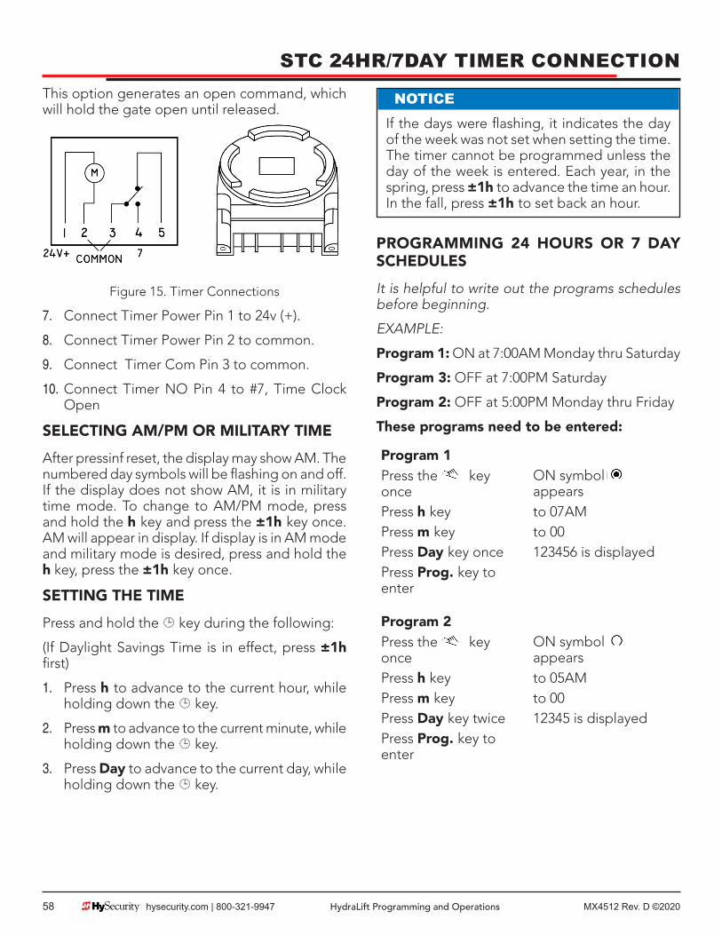
MX4512 Rev. D ©202058 hysecurity.com | 800-321-9947 HydraLift Programming and Operations
STC 24HR/7DAY TIMER CONNECTIONThis option generates an open command, which will hold the gate open until released.
Figure 15. Timer Connections
7. Connect Timer Power Pin 1 to 24v (+).
8. Connect Timer Power Pin 2 to common.
9. Connect Timer Com Pin 3 to common.
10. Connect Timer NO Pin 4 to #7, Time Clock Open
SELECTING AM/PM OR MILITARY TIME
After pressinf reset, the display may show AM. The numbered day symbols will be flashing on and off. If the display does not show AM, it is in military time mode. To change to AM/PM mode, press and hold the h key and press the ±1h key once. AM will appear in display. If display is in AM mode and military mode is desired, press and hold the h key, press the ±1h key once.
SETTING THE TIME
Press and hold the key during the following:
(If Daylight Savings Time is in effect, press ±1h first)
1. Press h to advance to the current hour, while holding down the key.
2. Press m to advance to the current minute, while holding down the key.
3. Press Day to advance to the current day, while holding down the key.
PROGRAMMING 24 HOURS OR 7 DAY SCHEDULES
It is helpful to write out the programs schedules before beginning.
EXAMPLE:
Program 1: ON at 7:00AM Monday thru Saturday
Program 3: OFF at 7:00PM Saturday
Program 2: OFF at 5:00PM Monday thru Friday
These programs need to be entered:
Program 1Press the key once
ON symbol appears
Press h key to 07AMPress m key to 00Press Day key once 123456 is displayedPress Prog. key to enter
Program 2Press the key once
ON symbol appears
Press h key to 05AMPress m key to 00Press Day key twice 12345 is displayedPress Prog. key to enter
NOTICEIf the days were flashing, it indicates the day of the week was not set when setting the time. The timer cannot be programmed unless the day of the week is entered. Each year, in the spring, press ±1h to advance the time an hour. In the fall, press ±1h to set back an hour.

MX4512 Rev. D ©2020 HydraLift Programming and Operations hysecurity.com | 800-321-9947 59
Program 3Press the key once
ON symbol appears
Press h key to 07AMPress m key to 00Press Day key twice until only 6 is
displayedPress Prog. key to enterPress key to enter Run Mode
IMPORTANT: If an "ON" time was programmed that is earlier than the current time, press once to turn the timer "ON." (It does not "look back" to determine if it should be on or off after programming.)
Up to 20 Programs are able to be entered at one time.
REVIEWING PROGRAMS
To review the programs at any time, press Prog. key. Programs will appear in the order they were entered with repeat presses of the Prog. key. After all programs have been reviewed, the blank display will appear to allow entering another program.
MANUAL OVERRIDE
TEMPORARY: While in the run mode, pressing, the key once will reverse the output; ON to OFF, or, OFF to ON. The symbol appears in the display to indicate a temporary override. At the next scheduled switching time, automatic control resumes eliminating the override. Continuous: While in the run mode...
zPressing the key twice will turn the output to ON permanently. symbol appears in display. zPressing the key three times will turn the output to OFF permanently. symbol appears in display. zTo terminate a continous override, press the key until appears in the display.
STC 24HR/7DAY TIMER CONNECTION

MX4512 Rev. D ©202060 hysecurity.com | 800-321-9947 HydraLift Programming and Operations
CONNECTING A RADIO RECEIVERMount a commercial style 24-Volt radio receiver (external antenna type) on the inside of the operator, below the electrical box. Knock out the smallest hole in the lower right corner of the electrical box and route the wires to the area marked Radio Options. Only three wire connections are needed because the 24-Volt supply and the radio output share a wire. Being certain to observe polarity, crimp the black radio power wire together with one of the radio output wires into a .25” spade connector and connect to the COM terminal. Connect the red wire to the +24V terminal and connect the other radio output contact wire to the spade marked OPEN. Note that this terminal is the same as the #4 input terminal labeled Edge Sensor on the main control board.
Mount an external antenna onto the top of a fixed post of the fence near the operator.
Connect the antenna into the socket on the radio receiver.
Set the DIP switches in the receiver to match the same code used in the transmitter.
If there is also to be an edge sensor transmitter to reverse the gate, be certain to use a two channel commercial receiver. Remember that each transmitter and receiver must have their codes set the same or they will not function.
Figure 16. Connecting a Radio Receiver

MX4512 Rev. D ©2020 HydraLift Programming and Operations hysecurity.com | 800-321-9947 61
TROUBLESHOOTINGTROUBLE WITH GATE MOVEMENT IN GENERAL:
1. Watch the pressure on the gauge while the gate is running. The gauge is a sensitive indicator of any spots that may be binding during travel. The pressure should be around 1,000 PSI and equal to slightly higher when closing and steady throughout the travel of the gate.
2. Stand away from the gate to verify that it is level, if not adjust the auto level cables.
3. Inspect the release sprockets in the base of each post and make certain the cap screw is tight.
ELECTRICAL PROBLEMS IN GENERAL:
The Smart Touch Controller reports system malfunctions on its LCD display and the buzzer will emit a series of chirps at defined intervals. Review the matrix of Alerts, Faults and Errors listed on the next page. To disclose the status of all inputs on the terminal strip, the LED tact button must be pushed. This button is in the upper left corner near the Stop input.
SPECIFIC TYPES OF PROBLEMS:
"I pushed the open and close buttons, but nothing runs."
1. Verify that the line voltage is present and matches the operator voltage + 10%.
2. In three phase applications insure that all three legs of line voltage pass though the power disconnect switch to the motor contactor, in case one of the lines is dropped somewhere.
3. Verify that control voltage is present at the power supply Common and 24VDC terminals. It may be necessary to reset the circuit breaker (black button) on the transformer.
4. Verify a jumper wire joins Common to Stop, if an external stop button is not used.
5. Verify there are no Faults or Errors reported on the LCD display. See table on the next page.
6. If the motor contactor chatters, voltage drop due to undersized wires is the likely cause. Check page 56 for maximum allowable length of wiring runs vs. wire size.

MX4512 Rev. D ©202062 hysecurity.com | 800-321-9947 HydraLift Programming and Operations
TROUBLESHOOTING"The pump is running but the gate panels don’t move."
(Hydraulic pressure is between 0 - 1000 PSI on the gauge)
1. If the power is three-phase, verify CCW motor rotation and reverse any two AC lines if needed.
2. Check the level of the hydraulic oil by removing the plug in the reservoir. If necessary, add oil at this location to within one inch of the filler hole.
3. Unplug the hoses and run the pump, look at the pressure gauge to confirm the system pressure reaches 2000 PSI. Re-attach the hoses when complete.
4. If relief pressure is not attained, remove the relief valve entirely and depress the plunger at the nose end with a blunt tool (large Allen wrench) and blow it to remove any debris. Return the valve to the power unit once cleaned.
“Hydraulic pressure is above 1000 PSI”
1. Verify that the quick connectors at the hose ends are fully seated when connected.
2. Check the brake valves where the hoses connect to the pump. They must not be turned too far counter-clockwise. See adjustment instructions on page 26.
3. Grab the gate panel and make certain it floats in its tracks, if it is bound fix the misalignment.
"The gate panels move in the wrong direction."
1. Check hose connections to verify the correct order of connection according to page 24.
2. With the system engaged to open, verify that the Open Valve coil develops a strong pull. (This can be tested by removing the nut retaining the coil and grasping the coil)
"The pumps starts correctly, but the gate only opens or only closes."
1. If the gate only opens, the directional valve is probably stuck and needs replacement.
2. If the gate only closes, the valve coil is not being energized, or is defective.

MX4512 Rev. D ©2020 HydraLift Programming and Operations hysecurity.com | 800-321-9947 63
The Smart Touch Controller system includes many self diagnostic capabilities. The LCD will display specific messages and the Audio Alert buzzer will sound distinctive chirps. Any Alerts, Faults or Errors are also logged into a memory and stamped with a time and date. For diagnostic purposes, these messages can be retrieved with optional WinLogger software available from Hy-Security Gate.
The following chart is a listing of codes that would appear on the LCD display if problems are detected by the Smart Touch Controller.
Table 6. TroublshootingError, Fault, or Alert Status LCD Display Buzzer Chirp Sequence
Cannot respond due to tripped sensor or in Entrapment mode Entr 2 chirps/sec every 2 seconds
while control input is active
Safety Mode Alert SAFE 2 chirps once when in Safety Mode
Low 24V Control Voltage Alert Lo24 (ac or dc) N/A (display flashes 1 sec every 5 seconds)
Critical Low 24V supply power BadP (ac or dc) N/A Display steady – controls disabled
Dead 24V Battery Alert –DC only bat - dEAd 3 chirps upon any operating
commandGate forced open Alert ALE1 2 pulses/sec for 30 secondsGate drift closed Alert ALE2 2 pulses/sec for 10 secondsMotor thermal overload Alert ALE4 2 chirps/sec every 15 secondsBoth limits tripped Alert ALE5 2 chirps/sec every 15 secondsLoop abnormal freq change alert ALE7 2 chirps/sec every 15 seconds
Loop shorted to ground alert ALE8 2 chirps/sec every 15 secondsLoop disconnected alert ALE9 2 chirps/sec every 15 secondsLoop detector comm. alert AL10 2 chirps/sec every 15 secondsLoop detector function alert AL11 2 chirps/sec every 15 secondsLoop detector active >5 minutes AL12 2 chirps/sec every 15 seconds
Maximum run Fault FAL1 1 chirp once every 15 secondsPhoto eye Fault (supervised) FAL2 2 chirps/sec once per minuteCritical AC sag – bad supply wire FAL3 2 chirps/sec once per minute
Directional motion Error Err1 3 chirps/sec once per minuteDisconnected IES Error Err2 3 chirps/sec once per minuteLoop detector failed Err3 3 chirps/sec once per minutePrimary/Secondary RS485 comm. Error Err4 3 chirps/sec once per minute
EEPROM Data Error (factory) Err7 3 chirps/sec once per minute
TROUBLESHOOTING

MX4512 Rev. D ©202064 hysecurity.com | 800-321-9947 HydraLift Programming and Operations
TROUBLESHOOTING
Table 7. TroublshootingEEPROM Data Error (installer) Err8 3 chirps/sec once per minuteEEPROM Data Error (user menu) Err9 3 chirps/sec once per minuteProgram Data Error FAiL 3 chirps/sec once per minute
The green LED near #2 on the terminal strip is the heartbeat of the processor. This LED should always blink brightly to indicate normal operation.
GATE SPEED: The speed in which a hydraulic operator moves a gate is determined by the size of the pump and the size of the actuator components. Just like a gear box, this speed is not adjustable. Attempting to slow a gate by changing any valve setting will cause a great deal of inefficiency and heat. If the speed of a gate must be changed, contact your Hy-Security distributor. Extremely cold weather is unlikely to seriously affect the speed of the gate, because Hy-Security employs a special grade of hydraulic oil that we call UNIFLOW oil, which maintains a very linear viscosity over a broad range of temperatures. Because of this high quality oil and other design considerations, we rate our operators for service in ambient temperatures of –40F degrees to 130F degrees. If the speed of your operator has been affected by cold weather, verify that the gate hardware s not impaired by ice and verify that the reservoir it is filled with UNIFLOW oil. In severe conditions, consider adding a heater.

MX4512 Rev. D ©2020 HydraLift Programming and Operations hysecurity.com | 800-321-9947 65
GENERAL MAINTENANCE: HVG OPERATOROPERATOR POST
After proper installation of the Hy-Security Vertical Lift Gate Operator, very little maintenance will be required to insure long and trouble free operation.
Quarterly:
3. The primary maintenance is to maintain the drive chain tension. The tension can be easily checked with the gate in the fully open position. Grasp the chain that is exposed on the outside of the post, it should always be slightly taut and never be loose. If adjustment is necessary:
a. Expose the chain adjustment area by removing the 2nd access cover, which is about three feet above the ground and raise the gate until fully open.
b. Locate the threaded rod connection to the bottom of the weight cage. Loosen the bottom locking nut and tighten the upper locking nut until there is appropriate chain tension. Be certain to retighten the locking nut.
Semi-Annually:
1. Each post has four bearings, which should receive one pump from a grease gun semi-annually.
2. Check the auto level cables for correct tension. With the gate in a level position, the cables should neither sag nor greatly compress the spring at the top of each post. Also inspect the cables for fraying, especially where they bend over the sheaves when the gate is closed.
3. Inspect the cable sheaves to make certain they rotate freely.
4. Apply a light spray oil to all of the chains.
HYDRAULIC SYSTEM
Fluid Level: Under normal conditions, hydraulic systems do not consume oil. Before adding any oil, check the system thoroughly for leaks. Remove the bright metal plug in the tank, fill to plug level, then replace plug. We recommend our Uniflow hydraulic oil; part number H004 1.0, which is sold in one-gallon containers by our distributors. Automatic transmission fluid may be used, although its performance in cold weather will be sluggish unless the operator is well heated. Never use brake fluid. It will severely damage the entire hydraulic system.
Look for leaks: Occasionally there may be slight seeping at the fittings after some usage. Tightening of the fittings will usually correct the problem. If the leaking persists, replace "O" rings, fittings or hoses, if required. No further leaks should occur.
Oil Change: A hydraulic system does not foul its oil, unlike a gas engine, so oil changes do not need to be frequent. Oil breakdown caused by heat is the main concern. If the unit is subjected to high use, especially in a warm climate, change the oil more frequently. In general, we recommend draining the reservoir and replacing the oil at five-year intervals.
To change the hydraulic oil, remove the reservoir from the pump unit and completely, empty it. Wipe the reservoir can clean and clean any debris from the pickup screen before re-assembling. Refill with new Uniflow hydraulic oil (available from your distributor). To avoid overfilling, fill only through removable plug near the top of the tank. Slowly pour the oil into the tank until the oil is within one inch of the filler port. Replace the plug and wipe up any spilled oil. If any oil is allowed to remain, it will dry to a very sticky and messy consistency.
Semi-Annually:
1. Check that your reservoir is filled with our Uniflow high performance oil, which is rated to -40°F.
2. Ice can partly or totally jam gate operation. In severe weather inspect the gate for excessive build-ups of snow and Ice.

MX4512 Rev. D ©202066 hysecurity.com | 800-321-9947 HydraLift Programming and Operations
GENERAL MAINTENANCEELECTRICAL CONTROLS
Before servicing, turn off power disconnect switch
No routine maintenance is needed for the electrical system or controls. If the environment is very sandy or dusty, or has many insects be certain to seal all holes in the electrical enclosure. Blow the dust out of the electric panel with compressed air. A qualified technician may troubleshoot with the aid of the troubleshooting guide in this appendix. If it is necessary to call a distributor for assistance, be sure to have your model and serial number ready. Other helpful information would include the name of the job, approximate date of installation, and the service record of the operator, especially any work that has been done recently.
PRESSURE RELIEF VALVES ADJUSTMENT PROCEDURES
To check your relief valve setting, first disconnect the hoses. Run the operator either open or closed (the gate will not move with the hose disconnected. The relief valve is found on the rear of the hydraulic power unit. It has an adjusting head and lock nut. To adjust, loosen the lock nut and screw the threaded bolt clockwise for increased pressure, counterclockwise to decrease pressure.
Table 8. Factory Pressure Relief SettingModel Factory Setting
HVG 420 & HVG 460 2000 PSIHVG 420 EX & HVG 460 EX 2000 PSI
There is only limited value in using the relief valve as an entrapment protection device. Photo Eyes or gate edges are the best methods to protect pedestrians and maintain reserve power to reliably drive the gate.
Figure 17. Timer ConnectionsPressure Relief Valves Adjustment

MX4512 Rev. D ©2020 HydraLift Programming and Operations hysecurity.com | 800-321-9947 67
MAINTENANCE SCHEDULEVERTICAL GATE OPERATOR MAINTENANCE SCHEDULE
Table 9. Vertical Gate Operator Maintenance Schedule
Name of Part
What To DoCheck at these recommended monthly intervals
1 3 6 12 60Gate Panel Check for damage *1 XGate tracking
Check for even pressure *2 X
Chain tension
Check for tightness *3 X
Lubrication Oil chains, grease bearings *4 X
Limit Switches
Check normal function *5 X
Auto Level Cable
Check tension & gate level X
Anchor Bolts
Check for tightness X
Fluid level Check for loss of fluid *6 X
Hydraulic fluid
Drain and replace fluid X
Clock battery Replace *7 X
Special Notes:
*1 Your gate will usually require more maintenance than the Hy-Security operator that is moving the gate. Damaged or warped gate panels are signs that a vehicle may have hit the gate. Verify that the actuator post is not also damaged.
*2 Normally, the gate moves with no scraping sounds and a steady pressure displayed on the gauge. If there is any damage, misalignment or maladjustment, the gate motion will not be smooth and the gauge will display pressure spikes in the stiff areas of travel. These conditions must be corrected.
*3 The drive chain should always have a slight tension. If necessary, adjust the chain tension at the bottom of the counterweight cage.
*4 The bearings in the post and all the chain should receive light lubrication every six months.
*5 To perform this inspection simply watch the position the gate stops. If adjustment is necessary, you will need to remove the lowest cover on the post, open the limit switch cover, and follow the instructions on page 14. Also see the brake valve adjustment instructions on page16.
*6 The oil level should remain approximately one inch below the filler hole. See maintenance instructions for oil filling. Loss of fluid is not normal and indicates a leak that must be located and repaired. Use “Uniflow” fluid, part H 004 1.0, if additional fluid is required.
*7 Replace the clock battery on the Smart Touch board with DL 2025 / DL 2032 or CR 2025 / CR 2032.

MX4512 Rev. D ©202068 hysecurity.com | 800-321-9947 HydraLift Programming and Operations
D.C. POWERED GATE OPERATOR SPECIAL NOTESThe on/off switch on the electric control panel of the drive unit does not disable all DC power to the operator, even if the AC power has been disabled at its source. The large rotary switch in the DC power supply enclosure must be actuated off to insure disconnect of all DC power to the drive unit.
The disconnect in the power supply must be off if the AC source power will be absent for more than one week. This avoids slowly discharging the batteries into the battery charger. Batteries will self-discharge and therefore the DC power supply must not be stored for a period longer than 6 months without recharging the batteries.
Batteries contain sulfuric acid. If batteries are dropped or damaged, be cautious not to get acid in the eyes, on skin, or on clothing.
Be certain to observe polarity when connecting the batteries, or adding accessories. Reversed polarity may result in a non-functional operator or possibly damage a component. Red is (+) positive, and black is (-) negative.
Since the electrical current under load is very high, be certain that the minimum conductor size, specified in the installation instructions, is used for the connection between the battery pack and the operator. If the battery pack is more than 20 feet from the operator, use a larger wire size, according to the distance between the operator and the batteries.
If shorted, batteries will generate a very high current. Observe special care when connecting the cables to the batteries that the polarity is correct. The batteries are connected in a series circuit: join the positive (+) terminal from one battery to the negative (-) terminal of the next battery.
Since this operator is intended to run on batteries, control of the load is important. Easier moving gates will drain less energy from the battery, preserving capacity for more cycles during a power failure.
Hy-Security uses a permanently sealed type battery, which needs no maintenance over its life span. A low voltage-sensing circuit protects the batteries from damage which could be caused by over-discharge. The charger automatically regulates its output to allow high output when the battery is partially discharged. The output will automatically be reduced to zero as the batteries become fully charged.
Batteries have a finite life. As the batteries age they will lose some of their capacity to store energy. If the total amount of back up capacity is critical, plan to replace the batteries after 5 years of use. Properly dispose of or recycle used batteries.
Batteries are rated to perform to capacity at a temperature of 77 degrees Fahrenheit. Below 77 degrees, the "amp hour" capacity is temporarily reduced. For example, at freezing, the capacity is 75%, at 10 degrees Fahrenheit, the capacity is 50%. Hy-Security insulates the battery pack to guard against this loss. Do not remove any insulation or the performance of the system may be adversely affected.
Batteries can be damaged by excessive heat, which may shorten their life span. Therefore, do not paint the battery enclosure a dark color that could cause it to absorb a lot of heat from sunlight.

MX4512 Rev. D ©2020 HydraLift Programming and Operations hysecurity.com | 800-321-9947 69
D.C. OPERATOR WIRING AND CONTROL CONFIGURATIONIf this installation is a 24-Volt DC battery type gate operator, there are a few additional steps that must be completed before the system can be functional. Review the installation instructions below and the connection diagram on page 70. Be certain the DC power disconnect switch is turned off before making any connections.
3. Connect minimum 2 gage wires between the battery enclosure and the gate operator as follows: Be certain to observe polarity carefully!
a. From the battery enclosure the (+) lead connects to the lug on the large rotary power disconnect switch. The (-) lead connects to the lug on the circuit breaker. At the gate operator the (+) lead connects directly to the lug on the top of the DC electric motor. The (-) lead connects to the bottom lug on the contactor mounted alongside the DC motor. All lug connections must be tightened very securely since they pass high current to the gate operator.
4. Connect two separate 14-gage circuits between the battery enclosure and the gate operator. One circuit provides the 24 VDC to the gate operator controls and the second circuit is required so that the Smart Touch Controller knows that the battery charger is operating normally on AC power. Be certain to observe polarity carefully!
a. Connect four wires to the terminal strip in the battery supply labeled: (+)24, (-)24, COM, #21. The 24 Volt (+) and (-) terminals connect to the red (+) and black (-) wires at the on/off power switch in the gate operator.
b. The COM and #21 terminals connect to the Common Buss and to terminal #21 (Charger AC power loss) on the Smart Touch Controller.
5. The Smart Touch Controller User Menu (U4) provides four optional system configurations for 24- Volt DC battery type gate operators. Since this is an uninterruptible power supply system, the installer must decide, depending upon customer preference, what is to happen when the AC line power fails. There are four functional choices provided in the User Menu, item [AP__].
Setting 0 (Type A): The operator functions normally until the batteries drop to 20 Volts, then auto open and lock until the battery voltage recovers to 23.5 Volts. The gate can still be manually closed only by a Close Pushbutton or an Emergency Close input and will then re-open by any open command until the battery voltage drops to 17 Volts at which time the gate is absolutely locked open.
Setting 1 (Type B): The operator functions normally until the batteries drop to 20 Volts, then auto close and lock closed until battery voltage recovers to 23.5 Volts. The gate can only be opened by a special combination of a Stop Pushbutton input, then within 1 second, an Open Pushbutton input. The Fire Department open input can open the gate without the special PBS enabling pre-input. The gate can be reclosed only by Close Pushbutton and the Emergency Close inputs. When the battery voltage drops to 17 Volts, the gate completes its final cycle and stays in the full open or full closed position, depending upon which cycle was last.
Setting 2 (Type C): The operator automatically opens five seconds after loss of AC power and locks open,until AC power is restored. The gate can still be manually closed only by a Close Pushbutton or an Emergency Close input and will then re-open by any open command until the battery voltage drops to 17 Volts at which time the gate is absolutely locked open.
Setting 3 (Type D): Same as type C, except the operator initially does nothing after loss of AC power, but then locks open after the next open command of any type.

MX4512 Rev. D ©202070 hysecurity.com | 800-321-9947 HydraLift Programming and Operations
BATTERY CONNECTION DIAGRAM

MX4512 Rev. D ©2020 HydraLift Programming and Operations hysecurity.com | 800-321-9947 71
BATTERY CONNECTION DIAGRAM

MX4512 Rev. D ©202072 hysecurity.com | 800-321-9947 HydraLift Programming and Operations
WIRE SIZE SCHEDULESFor 1/2-hp through 5-hp motors
Supplying a gate operator with the right electrical service is crucial to the way the performance of the operator the life of its electrical components. If the wire size used is too small, the voltage loss— especially during motor starting—will prevent the motor from attaining its rated horsepower. The percent of horsepower lost is far greater than the percentage of the voltage loss. A voltage loss could also cause the control components to chatter while the motor is starting, substantially reducing their life due to the resultant arcing. There is no way to restore the lost performance resulting from undersized wires, except to replace them; therefore it is much more economical to choose a sufficient wire size at the initial installation.
The tables on the following page are based on copper wire and allow for a 5% voltage drop. The ampere values shown are the service factor ampere rating (maximum full load at continuous duty) of the motor.
Always connect in accordance with the National Electrical Code, article 430, and other local codes that may apply.
The maximum distance shown is from the gate operator to the power source; assuming that source power is from a panel box with adequate capacity to support the addition of this motor load. The values are for one operator, with no other loads applied to the branch circuit. Avoid placing more than one gate operator to a circuit, but if you must be certain to reduce the maximum allowed distance by half.
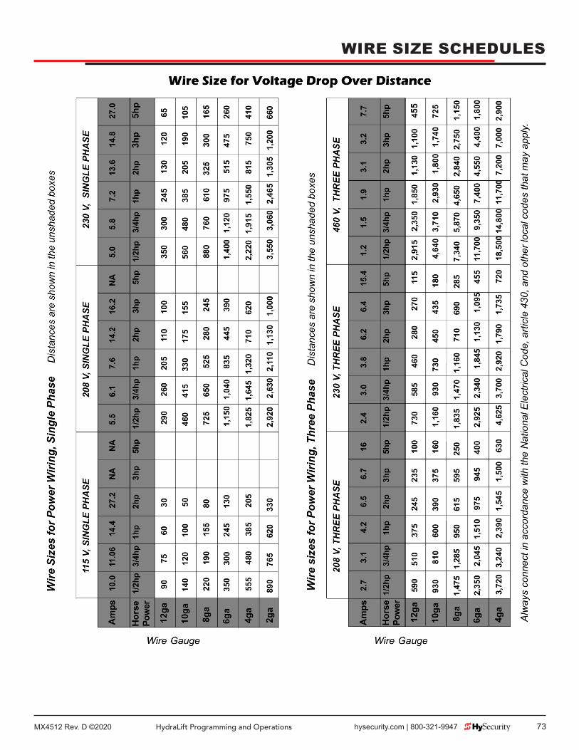
MX4512 Rev. D ©2020 HydraLift Programming and Operations hysecurity.com | 800-321-9947 73
WIRE SIZE SCHEDULES

MX4512 Rev. D ©202074 hysecurity.com | 800-321-9947 HydraLift Programming and Operations
HVG PUMP PACKS - PARTS BREAKOUT

MX4512 Rev. D ©2020 HydraLift Programming and Operations hysecurity.com | 800-321-9947 75
HVG EX PUMP PACKS - PARTS BREAKOUT

MX4512 Rev. D ©202076 hysecurity.com | 800-321-9947 HydraLift Programming and Operations
PARTS BREAKOUT – HVG CONTROL BOX

MX4512 Rev. D ©2020 HydraLift Programming and Operations hysecurity.com | 800-321-9947 77
PARTS BREAKOUT - DC POWER SUPPLY

MX4512 Rev. D ©202078 hysecurity.com | 800-321-9947 HydraLift Programming and Operations
PARTS BREAKOUT - DC POWER SUPPLY
Table 10. HVG420 PartsPart Number Description
ESWLS 228 VG Rotary Limit Switch CompleteESWLS 228 CB Limit Switch Contact (component of above part)H MOMO K10H Hydraulic Motor W/Quick Disc. FittingsH SFHO 006 4216 3/8" Hydraulic Hose, With FittingsH SFQD 004 P 1/4" Quick Disconnect (Plug)H SFQD 004 S 1/4" Quick Disconnect (Socket)M VLSV 001 5.0 5" Plastic Double Cable Sheave
M TBTC 001 1/8" Auto level Cable with End Fittings, sold by L/F
M PTBE 020 UHMW Angle Glide for BogieM PTBE 025 1" Tapped Base Pillow Block BearingM VLSP 420 T-R Top Shaft and Sprocket Assembly (2 Sprockets)
M VLSP 420 B Bottom Shaft and Sprocket Assembly (3 Sprockets)
M PTSP 001 3B12 #35-12 Tooth Limit Switch SprocketM PTSP 400 R #40-19 Tooth Quick Release SprocketM PTRC 040 #40 Roller Chain, PlatedM PTRC 035 #35 Roller Chain, Plated (Limit Switch)M PTRC 040 CON #40 Master Connecting LinkM PTRC 040 Off #40 Offset Connecting LinkM VLBO 420 Bogie (Gate Mount for HVG 420)M VLWC 420 Weight Cage (for HVG 420)

MX4512 Rev. D ©2020 HydraLift Programming and Operations hysecurity.com | 800-321-9947 79
Table 11. HVG460 PartsPart Number Description
ESWLS 228 VG Rotary Limit Switch CompleteESWLS 228 CB Limit Switch Contact (component of above part)H MOMO K10H Hydraulic Motor W/Quick Disc. FittingsH SFHO 006 4216 3/8" Hydraulic Hose, With Fittings sold by L/FH SFQD 004 P 1/4" Quick Disconnect Set (Plug)H SFQD 004 S 1/4" Quick Disconnect Set (Socket)M VLSV 001 5.0 5" Plastic Double Cable Sheave
M TBTC 001 1/8" Auto level Cable with End Fittings, sold by L/F
M PTBE 020 UHMW Angle Glide for BogieM PTBE 015 1-1/4" Tapped Base BearingM VLSP 460 T-R Top Shaft and Sprocket Assembly (2 Sprockets)
M VLSP 460 B Bottom Shaft and Sprocket Assembly (3 Sprockets)
M PTSP 001 3B12 #35-12 Tooth Limit Switch SprocketM PTSP 400 R #40-19 Tooth Quick Release SprocketM PTRC 050 #50 Roller Chain, Plated (Main support)M PTRC 040 #40 Roller Chain, Plated (Motor Drive)M PTRC 035 #35 Roller Chain, Plated (Limit Switch)M VLBO 460 Bogie (Gate Mount for HVG 460)M VLWC 460 Weight Cage (for HVG 460)
PARTS BREAKOUT - DC POWER SUPPLY

MX4512 Rev. D ©202080 hysecurity.com | 800-321-9947 HydraLift Programming and Operations
NOTES
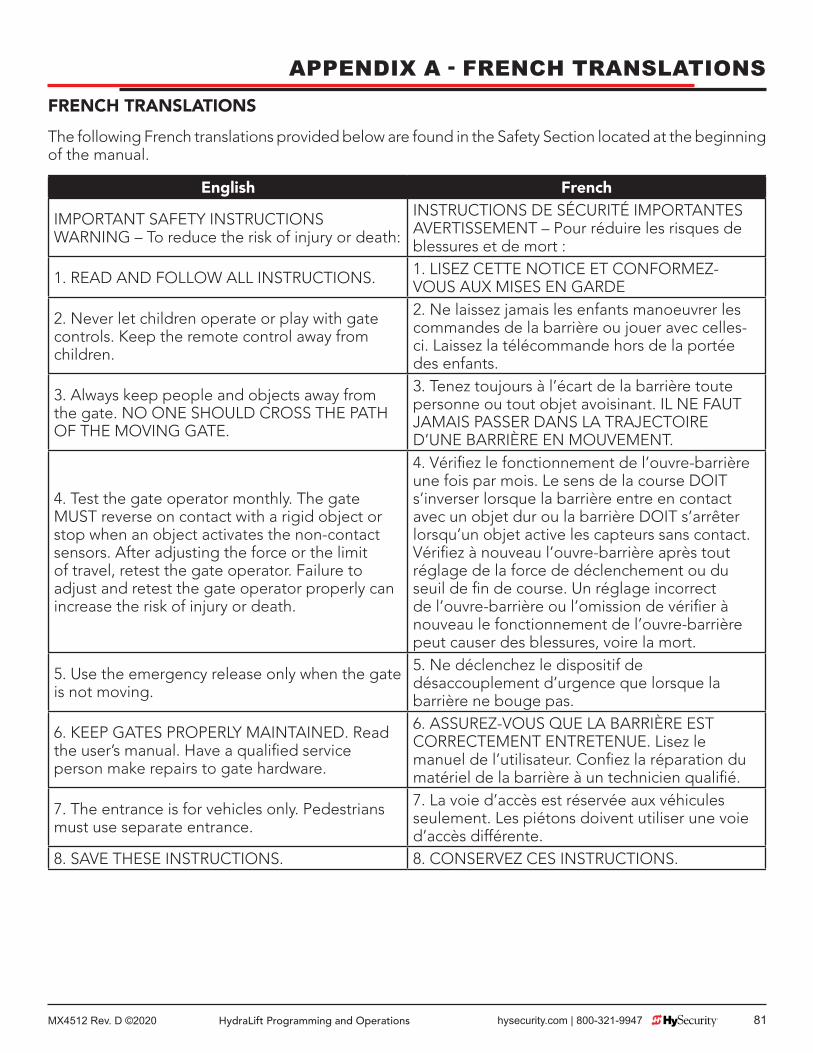
MX4512 Rev. D ©2020 HydraLift Programming and Operations hysecurity.com | 800-321-9947 81
APPENDIX A - FRENCH TRANSLATIONSFRENCH TRANSLATIONS
The following French translations provided below are found in the Safety Section located at the beginning of the manual.
English French
IMPORTANT SAFETY INSTRUCTIONS WARNING – To reduce the risk of injury or death:
INSTRUCTIONS DE SÉCURITÉ IMPORTANTES AVERTISSEMENT – Pour réduire les risques de blessures et de mort :
1. READ AND FOLLOW ALL INSTRUCTIONS. 1. LISEZ CETTE NOTICE ET CONFORMEZ-VOUS AUX MISES EN GARDE
2. Never let children operate or play with gate controls. Keep the remote control away from children.
2. Ne laissez jamais les enfants manoeuvrer les commandes de la barrière ou jouer avec celles-ci. Laissez la télécommande hors de la portée des enfants.
3. Always keep people and objects away from the gate. NO ONE SHOULD CROSS THE PATH OF THE MOVING GATE.
3. Tenez toujours à l’écart de la barrière toute personne ou tout objet avoisinant. IL NE FAUT JAMAIS PASSER DANS LA TRAJECTOIRE D’UNE BARRIÈRE EN MOUVEMENT.
4. Test the gate operator monthly. The gate MUST reverse on contact with a rigid object or stop when an object activates the non-contact sensors. After adjusting the force or the limit of travel, retest the gate operator. Failure to adjust and retest the gate operator properly can increase the risk of injury or death.
4. Vérifi ez le fonctionnement de l’ouvre-barrière une fois par mois. Le sens de la course DOIT s’inverser lorsque la barrière entre en contact avec un objet dur ou la barrière DOIT s’arrêter lorsqu’un objet active les capteurs sans contact. Vérifi ez à nouveau l’ouvre-barrière après tout réglage de la force de déclenchement ou du seuil de fi n de course. Un réglage incorrect de l’ouvre-barrière ou l’omission de vérifi er à nouveau le fonctionnement de l’ouvre-barrière peut causer des blessures, voire la mort.
5. Use the emergency release only when the gate is not moving.
5. Ne déclenchez le dispositif de désaccouplement d’urgence que lorsque la barrière ne bouge pas.
6. KEEP GATES PROPERLY MAINTAINED. Read the user’s manual. Have a qualifi ed service person make repairs to gate hardware.
6. ASSUREZ-VOUS QUE LA BARRIÈRE EST CORRECTEMENT ENTRETENUE. Lisez le manuel de l’utilisateur. Confi ez la réparation du matériel de la barrière à un technicien qualifi é.
7. The entrance is for vehicles only. Pedestrians must use separate entrance.
7. La voie d’accès est réservée aux véhicules seulement. Les piétons doivent utiliser une voie d’accès différente.
8. SAVE THESE INSTRUCTIONS. 8. CONSERVEZ CES INSTRUCTIONS.

MX4512 Rev. D ©202082 hysecurity.com | 800-321-9947 HydraLift Programming and Operations
APPENDIX A - FRENCH TRANSLATIONS
English French2.3 Install the gate operator only when: 2.3 N’installez l’ouvre-barrière que si :a. The operator is appropriate for the construction of the gate and the usage Class of the gate,
a. l’ouvre-barrière est approprié pour la structure et la classe d’utilisation de la barrière;
b. All openings of a horizontal slide gate are guarded or screened from the bottom of the gate to a minimum of 1.83 m (6 ft) above the ground to prevent a 57.2 mm (2-1/4 inch) diameter sphere from passing through the openings anywhere in the gate, and in that portion of the adjacent fence that the gate covers in the open position,
toutes les ouvertures de la barrière coulissante sont protégées ou grillagées du bas de la porte jusqu’à un minimum de 1,83 m (6 pi) du sol si bien qu’une sphère de 57,2 mm (2 1/4 po) de diamètre ne peut passer par une ouverture au niveau de la barrière et de la portion de la clôture adjacente que la barrière couvre en position ouverte;
c. All exposed pinch points are eliminated or guarded, and
c. tous les points de pincement sont éliminés ou protégés;
d. Guarding is supplied for exposed rollers. d. des protections sont fournies pour les galets exposés.
2.4 The operator is intended for installation only on gates used for vehicles. Pedestrians must be supplied with a separate access opening. The pedestrian access opening shall be designed to promote pedestrian usage. Locate the gate such that persons will not come in contact with the vehicular gate during the entire path of travel of the vehicular gate.
2.4 L’ouvre-barrière est destiné à n’être installé que sur des barrières utilisées pour les véhicules. Il faut fournir une autre voie d’accès aux piétons. La voie d’accès pour les piétons doit être conçue pour favoriser le passage des piétons. Placez la barrière de sorte que personne ne puisse entrer en contact avec la barrière pour les véhicules sur l’ensemble de sa trajectoire
2.5 The gate must be installed in a location so that enough clearance is supplied between the gate and adjacent structures when opening and closing to reduce the risk of entrapment. Swinging gates shall not open into public access areas.
c) Pour réduire les risques de coincement lors de l’ouverture et de la fermeture, la barrière doit être installée dans un endroit où la barrière et les structures avoisinantes sont suffi samment éloignées l’une de l’autre. Les barrières battantes ne doivent pas ouvrir dans une zone d’accès public.

MX4512 Rev. D ©2020 HydraLift Programming and Operations hysecurity.com | 800-321-9947 83
APPENDIX A - FRENCH TRANSLATIONS
English French
2.6 The gate must be properly installed and work freely in both directions prior to the installation of the gate operator. Do not over-tighten the operator clutch or pressure relief valve to compensate for a damaged gate.
2.6 La barrière doit être bien installée et fonctionner librement dans les deux directions avant d’entreprendre l’installation de l’ouvre-barrière. Ne serrez pas trop l’embrayage ou la soupape de surpression de l’ouvre-barrière pour compenser une barrière endommagée.
2.7 Controls intended for user activation must be located at least 1.83 m (6 ft) away from any moving part of the gate and where the user is prevented from reaching over, under, around or through the gate to operate the controls. Exception: Emergency access controls only accessible by authorized personnel (e.g. fi re, police, EMS) may be placed at any location in the line-of-sight of the gate.
2.7 Les commandes destinées à l’activation par l’utilisateur doivent être situées à au moins 1,83 m (6 pi) des pièces mobiles de la barrière et à un endroit où l’utilisateur ne peut pas atteindre les commandes par le dessus, par le dessous, par les côtés et au travers de la barrière. Exception : Les commandes d’accès d’urgence accessibles au personnel autorisé seulement (p. ex. pompier, policier, SMU) peuvent être placées à tout endroit dans le champ de visibilité de la barrière.
2.8 The Stop and/or Reset button must be located in the line of-sight of the gate. Activation of the reset control shall not cause the operator to start.
2.8 Le bouton d’arrêt, le bouton de réenclenchement ou ces deux boutons doivent être situés dans le champ de visibilité de la barrière. L’activation des commandes de réenclenchement ne doit pas mettre en marche l’ouvrebarrière.
2.9 A minimum of two (2) WARNING SIGNS shall be installed, in the area of the gate. Each placard is to be visible by persons located on the side of the gate on which the placard is installed.
2.9 Au moins deux panneaux de mise en garde doivent être installés dans la zone de la barrière. Chaque étiquette doit être visible des personnes situées de chaque côté de la barrière sur laquelle l’étiquette est installée.
2.10 For gate operators utilizing a non-contact sensor
2.10 Pour les ouvre-barrières qui fonctionnent avec des capteurs
a. See instructions on the placement of non-contact sensors for each Type of application,
a. Voir les instructions sur le positionnement des capteurs sans contact pour chaque type d’utilisation.
b. Care shall be exercised to reduce the risk of nuisance tripping, such as when a vehicle, trips the sensor while the gate is still moving, and
b. Des précautions doivent être prises pour réduire les risques de déclenchement inutile, comme lorsqu’un véhicule déclenche le capteur alors que la barrière est encore en mouvement.
c. One or more non-contact sensors shall be located where the risk of entrapment or obstruction exists, such as the perimeter reachable by a moving gate or barrier.
c. Un capteur sans contact ou plus doit être situé où il existe un risque de coincement ou d’obstruction, comme dans l’espace que peut occuper la barrière lorsqu’elle est en mouvement.
2.11 For a gate operator utilizing a contact sensor
2.11 Pour les ouvre-barrières qui fonctionnent avec des capteurs

MX4512 Rev. D ©202084 hysecurity.com | 800-321-9947 HydraLift Programming and Operations
APPENDIX A - FRENCH TRANSLATIONS
English French
a. One or more contact sensors shall be located where the risk of entrapment or obstruction exists, such as at the leading edge, trailing edge, and postmounted both inside and outside of a vehicular horizontal slide gate.
a. Au moins un capteur de contact doit être situé où il existe un risque de coincement ou d’obstruction, comme sur le bord d’ouverture, sur le bord de fermeture et sur les poteaux montés sur l’intérieur ou l’extérieur d’une barrière coulissante pour véhicules.
b. A hardwired contact sensor shall be located and its wiring arranged so that the communication between the sensor and the gate operator is not subjected to mechanical damage.
b. Un capteur de contact doit être installé et câblé de sorte à éviter que la communication entre le capteur et l’ouvrebarrière soit gênée par des dommages mécaniques.
c. A wireless device such as one that transmits radio frequency (RF) signals to the gate operator for entrapment protection functions shall be located where the transmission of the signals are not obstructed or impeded by building structures, natural landscaping or similar obstruction. A wireless device shall function under the intended end-use conditions.
c. Un dispositif sans fi l, comme un appareil qui transmet des signaux de radiofréquence (RF) à l’ouvre-barrière pour prévenir le coincement, doit être situé à un endroit où la transmission des signaux ne sera pas obstruée ou gênée par des structures, des arbres ou d’autres obstacles similaires. Un dispositif sans fi l doit fonctionner selon les conditions d’utilisation fi nale prévues.
d. One or more contact sensors shall be located on the inside and outside leading edge of a swing gate. Additionally, if the bottom edge of a swing gate is greater than 152 mm (6 inches) but less than 406 mm (16 inches) above the ground at any point in its arc of travel, one or more contact sensors shall be located on the bottom edge.
d. Au moins un capteur de contact doit être situé sur les bords d’ouverture intérieur et extérieur d’une barrière battante. De plus, si le dessous d’une barrière battante est situé à plus de 152 mm (6 po) mais à moins de 406 mm (16 po) du sol à l’un des points de sa trajectoire, au moins un capteur de contact doit être situé sur le bord inférieur.

MX4512 Rev. D ©2020 HydraLift Programming and Operations hysecurity.com | 800-321-9947 85
(This page intentionally blank)

MX4512 Rev. D ©202086 hysecurity.com | 800-321-9947 HydraLift Programming and Operations
WARRANTY
HySecurity Warranty D0317 Revised 032919 Page 1 of 1
6705 S 209th St, Ste 101 Kent, WA 98032
800-321-9947 www.hysecurity.com WARRANTY
1. Warranty. Hy-Security Gate, Inc. (“HySecurity”) warrants that at the �me of sale each
HySecurity-branded product that it sells will, in all material respects, conform to its then applicable specifica�on and will be free from defects in material and manufacture.
The following addi�onal dura�onal warran�es apply to HySecurity products, depending on whether (1) the product is purchased through an authorized HySecurity distributor and (2) whether a �mely and complete product registra�on is submited to HySecurity.
It is therefore important that you register your product with HySecurity, online at www.hysecurity.com/warranty, within the 60-day period described below.
1(a) HySecurity Products Purchased Through Authorized Distributors and Properly Registered
For any gate operator product that is purchased from an authorized HySecurity distributor (this excludes product purchased through internet resellers or any distributor not authorized by HySecurity), if the product registra�on is completed by the Dealer/Installer or End User within 60 days of the date of purchase, the following warranty terms will apply. HySecurity warrants that the product will remain serviceable for the following periods:
a) Hydraulic industrial gate operator hydraulics, controls, and mechanical components: Five Years or 500,000 gate cycles (whichever occurs first) a�er the date of installa�on,
b) Hydraulic wedge operator hydraulics and controls: Five Years or 500,000 cycles (whichever occurs first) a�er the date of installa�on. Wedge mechanical components: Two Years a�er the date of installa�on,
c) Electromechanical pad-mounted Slide and Swing operators: Five Years or 500,000 cycles (whichever occurs first) a�er the date of installa�on, except single family residen�al usage, where the warranty term shall be Seven Years a�er the date the product was shipped from HySecurity,
d) Electromechanical linear actuator Swing operators: Two Years a�er the date of installa�on,
e) Electromechanical surface mount wedge operator electronics: Two Years or 500,000 gate cycles (whichever occurs first), a�er the date of installa�on,
f) Electromechanical Barrier Arm Operators: Two years or 1,000,000 gate cycles (whichever occurs first) a�er the date of installa�on,
provided that the preceding Five Year warranty period in (a), (b), and (c) will not extend beyond seven years from the date that the product was shipped from HySecurity, and the Two Year warranty period in (b), (d), (e), and (f) will not extend beyond four years from the date that the product was shipped from HySecurity.
The preceding warranty dura�ons do not apply to the products or components described below (g-j), which have a shorter warranty period:
g) Hydraulic gate operator drive wheels, including XtremeDrive™ wheels and rack: Two Years from date of installa�on.
h) AC and DC power supplies, chargers, and inverters and HyNet™ Gateway: Two Years from date of installa�on, except bateries.
i) Bateries: One Year from date of shipment from HySecurity. j) Components subject to normal wear including, but not limited to, chains, belts,
idler wheels, sprockets and fuses: One Year from date of installa�on.
1(b) HySecurity Products Not Purchased Through an Authorized Distributor or Not Properly Registered within 60 Days
For any product that is not purchased from an authorized HySecurity distributor or for which the product registra�on was not completed by the Dealer/Installer/End User within sixty (60) days of the date of purchase, the following warranty will apply: HySecurity warrants that the product will remain serviceable for the following periods, which begin on the date that the product was shipped from HySecurity:
a) All gate operators: One Year or 100,000 gate cycles, whichever comes first. b) AC and DC power supplies, chargers, or inverters: One Year. c) HyNet™ Gateway: One Year. d) Hydraulic gate operator drive wheels: One Year.
1(c) Replacement Parts HySecurity warrants that replacement parts (whether new or recondi�oned) will
remain serviceable for One Year from the date that the part was shipped from HySecurity or the remaining period of the Gate Operator warranty, whichever is longer.
1(d) Limita�ons and Exclusions Applicable to Each of the Preceding Warran�es. The preceding warran�es shall not apply to equipment that has been (1) installed,
maintained, or used improperly or contrary to instruc�ons; (2) subjected to negligence, accident, vandalism, or damaged by severe weather, wind, flood, fire,
terrorism or war; or (3) damaged through improper opera�on, maintenance, storage or abnormal or extraordinary use or abuse. Any modifica�on made to products will void the warranty unless the modifica�ons are approved in wri�ng by HySecurity in advance of the change (this exclusion does not apply to normal installa�on of approved accessories and/or protec�ve devices or sensors). It is the responsibility of the Distributor, Dealer/Installer, or End User to ensure that the so�ware version in the product is maintained to the latest revision level.
The preceding warran�es do not extend to accessories when those items carry another manufacturer’s name plate and they are not a part of the base model. HySecurity disclaims all warran�es for such accessory components, which carry only the original warranty, if any, of their original manufacturer. HySecurity hereby assigns its rights under such manufacturer warran�es—to the extent that such rights are assignable—to Buyer.
These warran�es extend to HySecurity’s Distributors, to the Dealer/Installer, and to the first End User of the product following installa�on. They do not extend to subsequent purchasers.
2. Exclusion of Other Warran�es. The warran�es contained in Sec�on 1 are the exclusive warran�es given by
HySecurity and supersede any prior, contrary or addi�onal representa�ons, whether oral or writen. Any prior or extrinsic representa�ons or agreements are discharged or nullified. HYSECURITY HEREBY DISCLAIMS AND EXCLUDES ALL OTHER WARRANTIES—WHETHER EXPRESS, IMPLIED, OR STATUTORY—INCLUDING ANY WARRANTY OF MERCHANTABILITY, ANY WARRANTY OF FITNESS FOR A PARTICULAR PURPOSE, ANY LIABILITY FOR INFRINGEMENT, AND ANY WARRANTIES OTHERWISE ARISING FROM COURSE OF DEALING, COURSE OF PERFORMANCE, OR USAGE OF TRADE.
3. Buyer’s Exclusive Remedies for Any Nonconformity. If a HySecurity product fails to conform to the warran�es in Sec�on 1, Buyer must
no�fy and order replacement parts from the Distributor through which the product was purchased within a reasonable �me and in no event more than thirty (30) days a�er the discovery of the nonconformity. HySecurity will inves�gate and, in the event of a breach, will provide, within a reasonable period of �me, one of the following: (1) repair or replacement of any nonconforming products or components or (2) refund of the price upon return of the nonconforming items. HySecurity reserves the right to supply used or recondi�oned material for all warranty claims. HySecurity will not be considered to be in breach of or default under this Warranty because of any failure to perform due to condi�ons beyond its reasonable control, including any force majeure. This warranty does not cover any incidental expenses, including fines or penal�es, temporary security, labor, shipping, travel �me or standby �me that are incurred for inspec�on or replacement of any nonconforming items. As a condi�on of warranty coverage, warranty claims must be submited in accordance with the procedures described on the HySecurity form, “RMA Procedures.”
THE REMEDY SELECTED BY HYSECURITY IN ACCORDANCE WITH THIS PARAGRAPH SHALL BE THE EXCLUSIVE AND SOLE REMEDY OF BUYER FOR ANY BREACH OF WARRANTY.
4. Exclusion of Consequen�al and Incidental Damages. HYSECURITY SHALL NOT BE LIABLE FOR ANY INCIDENTAL, SPECIAL, OR
CONSEQUENTIAL DAMAGES, WHETHER RESULTING FROM NONDELIVERY OR FROM THE USE, MISUSE, OR INABILITY TO USE THE PRODUCT OR FROM DEFECTS IN THE PRODUCT OR FROM HYSECURITY’S OWN NEGLIGENCE. This exclusion applies regardless of whether such damages are sought for breach of warranty, breach of contract, negligence, or strict liability. This exclusion does not apply to claims for bodily injury or death.
5. Severability. If any provision of this warranty is found to be invalid or unenforceable, then the
remainder shall have full force and effect.
6. Proprietary Rights. HySecurity retains and reserves all right, �tle, and interest in the intellectual
property rights of its products, including any accompanying proprietary so�ware. No ownership of any intellectual property rights in the products or accompanying so�ware is transferred to Distributor, Dealer/Installer, or End User.
7. Applicable Law. This warranty will be interpreted, construed, and enforced in all respects in
accordance with the laws of the State of Washington, without reference to its choice of law principles. The U.N. Conven�on on Contracts for the Interna�onal Sale of Goods will not apply to this warranty.

MX4512 Rev. D ©2020 HydraLift Programming and Operations hysecurity.com | 800-321-9947 87
(This page intentionally blank)

MX4512 Rev. D ©202088 hysecurity.com | 800-321-9947 HydraLift Programming and Operations
17
FAST Operators Standard Heavy Duty Standard Fast Heavy Duty Fast
Model HydraLift 10 HydraLift 20 Hydralift 10F HydraLift 20F
Part# HVG 420 ST HVG 460 ST HVG 420 EX ST HVG 460 EX ST
Duty Cycle Continuous
Horsepower 2 hp 5 hp
Drive Hydraulic
Gate Weight Max. 1,000 lb (453 kg) 2,000 lb (907 kg) 1,000 lb (453 kg) 2,000 lb (907 kg)
Gate Length Max. 50 ft (15 m) 80 ft (24 m) 50 ft (15 m) 80 ft (24 m)
Rate of Travel 1 ft/s (30 cm/s) 2 ft/s (60 cm/s)
Temperature Rating -40º F to 158º F (-40º C to 70º C)
1 Phase Power** 208/230V 60Hz, 220V 50Hz 230V 60Hz
3 Phase Power** 208/230/460V 60Hz; 220/380V 50Hz 208/230/460V 60Hz; 220/380V 50Hz
Communication RS-232, RS-485, Ethernet/fi ber using optional HyNet™ Gateway accessory
User Controls Smart Touch Controller with 70+ confi gurable settings. Smart Touch keypad and display or a PC using S.T.A.R.T. software.
Relays Three confi gurable user relays: one 30VDC, 3A solid state and two 250VAC, 10A electromechanical; Optional Hy8Relay™ for 8 additional output relays
Finish Hot dipped galvanized lifting posts
Enclosure HydraSupply: Type 3R, 30w x 42h X 12d inch (76w x 107h x 30.5d cm)
ETL Listed (UL 325) Usage Class I, II, III, IV Usage Class III, IV
Warranty 5 year w/product registration
UPS Battery Backup Power*
DC Power Supply*† HydraLift 10 UPS HydraLift 20 UPS HydraLift 10F UPS HydraLift 20F UPS
* HydraLift 10, 20: 1,500 cycles/day expected duty cycle. HydraLift 10F, 20F: 1,000 cycles/day expected duty cycle. The operator’s normal duty cycle and the actual number of gate cycles available from battery depends upon gate resistance to travel, cycle length, battery size, state of charge and health, ambient temperature, accessory power draw and frequency of gate cycles during power outage.
** Refer to Installed Options on pricing for all 50Hz voltages, which are special order.† 115V DC Power Supply requires a 30A branch circuit. Choose voltage with care as chargers are not fi eld convertible.
This gate operator requires an external entrapment protection sensor to monitor the close direction of travel. Visit hysecurity.com/gatesafety for more information on UL 325 standards and gate safety.
8 HydraLift™ Models
SPECIFICATIONS
Contact Information:Visit https://hysecurity.com/technical-support/ for installation manuals, replacement part instructions, part diagrams and more.Qualified HySecurity distributors are experienced and trained to assist in resolving installation problems. For the name of a qualified distributor near you, call HySecurity at 800-321-9947. *Before contacting your distributor or HySecurity Technical Support, obtain the serial number of your operator.