hyd ham tool manual - npk construction · pdf filesee carrier machine compatibility section...
TRANSCRIPT

HYDRAULIC HAMMER
TOOL MANUAL
“Use Genuine NPK Parts”
7550 Independence Drive Walton Hills, OH 44146-5541
Phone (440) 232-7900 Toll-free (800) 225-4379
Fax (440) 232-6294 © Copyright 2007 NPK Construction Equipment, Inc. www.npkce.com H040-9600C.doc 08/07

1
CONTENTS SAFETY ............................................................................................................................ 2 INTRODUCTION............................................................................................................... 4 TOOL WARRANTY........................................................................................................... 5 PRECAUTIONS FOR USING NPK HAMMER TOOLS ..................................................... 7 IMPACT ENERGY TRANSMISSION THROUGH TOOLS ................................................ 8 TOOL LUBRICATION ....................................................................................................... 10 CORRECT GREASE FOR HYDRAULIC HAMMERS ....................................................... 11 NPK HAMMER GREASE .................................................................................................. 12 CORRECT USE OF NPK TOOLS..................................................................................... 13 TYPES AND APPLICATIONS OF TOOL .......................................................................... 17 TOOL BREAKAGE............................................................................................................ 18 CHISEL TOOL RESHARPENING..................................................................................... 26 STANDARD LENGTH FOR NPK TOOLS ......................................................................... 27 TOOL IDENTIFICATION................................................................................................... 28

2
SAFETY Safety notices in NPK Instruction Manuals follow ISO and ANSI standards for safety warnings:
DANGER (red) notices indicate an imminently hazardous situation which, if not avoided, will result in death or serious injury. WARNING (orange) notices indicate a potentially hazardous situation which, if not avoided, could result in death or serious injury. CAUTION (yellow) notices indicate a potentially hazardous situation, which, if not avoided, may result in minor or moderate injury. ATTENTION (blue) notices in NPK Instruction Manuals are an NPK standard to alert the reader to situations which, if not avoided, could result in equipment damage.
WARNING and BASIC OPERATING INSTRUCTIONS decals are included with each NPK hammer and installation kit. Decals must be installed in the cab, visible to the operator while operating the hammer. STAY CLEAR, PRESSURE VESSEL, GAS PRESSURE and TOOL SHARPENING decals are installed on all NPK hammer models. Keep them clean and visible. NPK will provide decals free of charge as needed.
1. Operator and Service personnel must read and understand the NPK INSTRUCTION MANUAL to prevent serious or fatal injury.
2. FLYING DEBRIS CAN CAUSE SERIOUS OR FATAL INJURY. • Keep personnel and bystanders clear of hammer while in operation. • Do not operate HAMMER without an impact
resistant guard between HAMMER and operator. NPK recommends LEXAN or equivalent material, or steel mesh. Some carrier manufacturers offer demolition guards for their machine. Check with the carrier manufacturer for availability. If not available, please call NPK.
3. Do not hardface or sharpen the tool point with a cutting torch. Excessive heat from torching or welding can cause embrittlement, breakage, and flying pieces. Resharpen by milling or grinding only, using sufficient coolant.

3
SAFETY, CONTINUED
4. Fully extend the tool while charging the HAMMER with nitrogen gas. Be sure that
the retaining pin is installed. STAY CLEAR OF TOOL POINT WHILE CHARGING. 5. Do not disassemble a HAMMER before discharging the hammer gas pre-charge. 6. USE NITROGEN GAS ONLY! Store and handle nitrogen tanks per OSHA
regulations. 7. Avoid high pressure fluids. Escaping fluid under pressure can penetrate the skin
causing serious injury. Relieve pressure before disconnecting hydraulic or other lines.
8. Operate HAMMER from operator’s seat only. 9. Match HAMMER size to carrier according to NPK recommendations. The carrier
must be stable during hammer operation and during transport. See CARRIER MACHINE COMPATIBILITY section of the NPK Hydraulic Hammer Operators Manual.
10. Do not make any alterations to the TOOL without authorization from NPK Engineering.
11. Use proper lifting equipment and tools when handling or servicing the HAMMER. 12. Wear ear protection and safety glasses when operating the hammer. Consult
OSHA/MSHA regulations when applicable. 13. Beware of flying metal pieces when driving boom pins. 14. If modifications are to be made, do not alter the HAMMER without authorization
from NPK Engineering! 15. Use only genuine NPK replacement parts. NPK specifically disclaims any
responsibility for any damage or injury that results from the use of any tool or parts not sold or approved by NPK.
For further safety information, consult the AEM Hydraulic Mounted Breakers Safety Manual, AEM form MB-140 (NPK P/N H050-9600), which is furnished with every NPK hammer. To request an additional copy, please contact NPK at 800-225-4379 or Internet at www.npkce.com.

4
INTRODUCTION This manual will assist NPK Dealers and Customers to obtain the longest possible life from NPK Demolition Tools. Customers can use this manual to take corrective action when tool breakage occurs. Dealers can use this manual to determine if tool breakage can be claimed under warranty. Refer to the NPK Demolition Tool Warranty statement for specifics of warranty coverage.
5
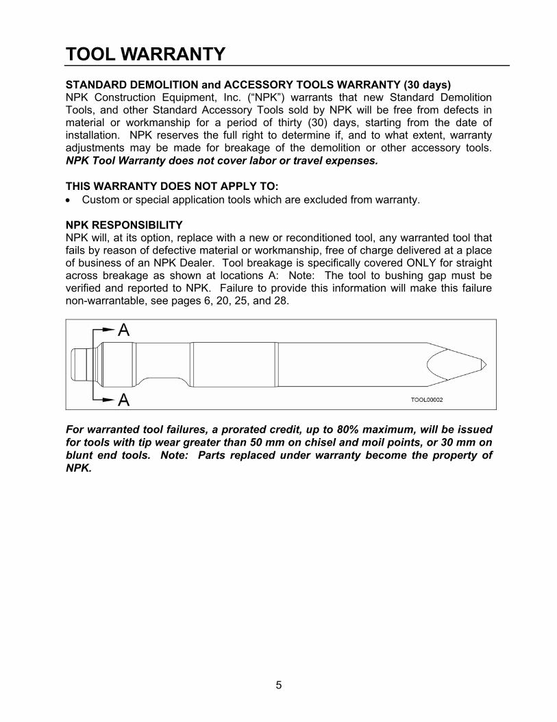
TOOL WARRANTY STANDARD DEMOLITION and ACCESSORY TOOLS WARRANTY (30 days) NPK Construction Equipment, Inc. (“NPK”) warrants that new Standard Demolition Tools, and other Standard Accessory Tools sold by NPK will be free from defects in material or workmanship for a period of thirty (30) days, starting from the date of installation. NPK reserves the full right to determine if, and to what extent, warranty adjustments may be made for breakage of the demolition or other accessory tools. NPK Tool Warranty does not cover labor or travel expenses. THIS WARRANTY DOES NOT APPLY TO: • Custom or special application tools which are excluded from warranty. NPK RESPONSIBILITY NPK will, at its option, replace with a new or reconditioned tool, any warranted tool that fails by reason of defective material or workmanship, free of charge delivered at a place of business of an NPK Dealer. Tool breakage is specifically covered ONLY for straight across breakage as shown at locations A: Note: The tool to bushing gap must be verified and reported to NPK. Failure to provide this information will make this failure non-warrantable, see pages 6, 20, 25, and 28.
For warranted tool failures, a prorated credit, up to 80% maximum, will be issued for tools with tip wear greater than 50 mm on chisel and moil points, or 30 mm on blunt end tools. Note: Parts replaced under warranty become the property of NPK.
6
TOOL WARRANTY, CONTINUED
USER RESPONSIBILITY • Photos and all numbers from retaining pin slot must accompany all warranties
submitted to NPK. These photos can be 35 mm, polaroid, or digital. • The installer, user, operator, repairer, assumes responsibility to read, understand
and comply with NPK’s written INSTALLATION, OPERATOR, and SERVICE INSTRUCTIONS.
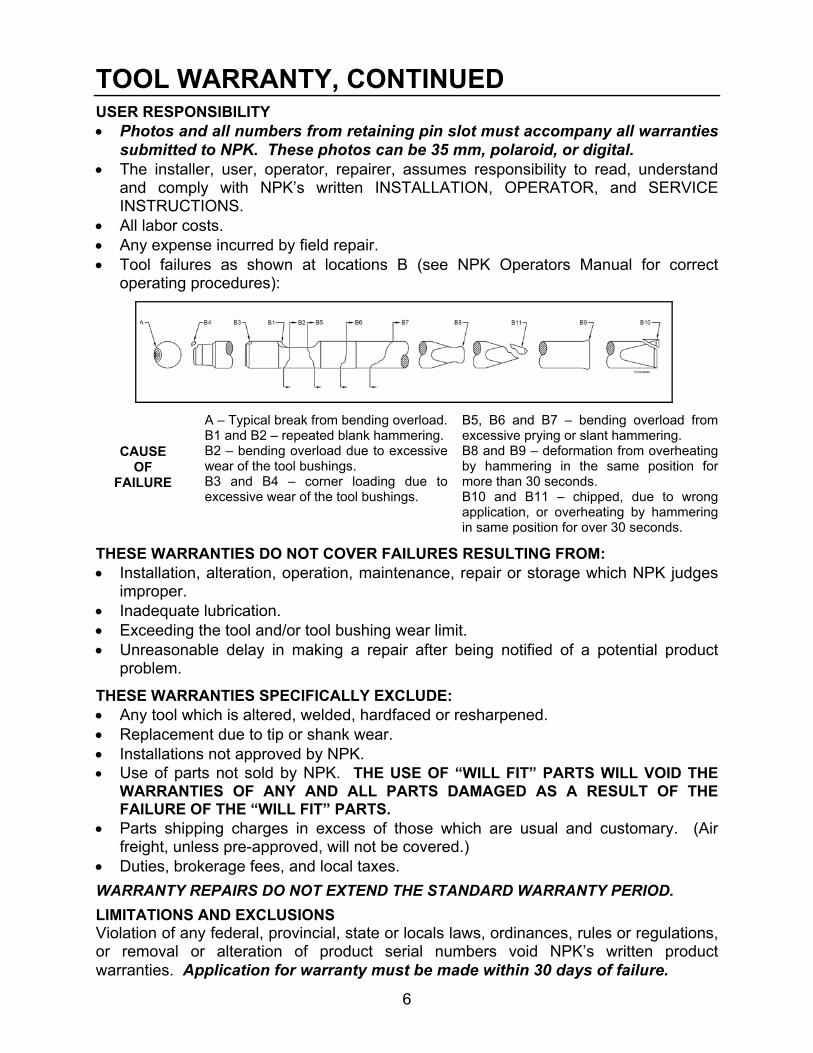
• All labor costs. • Any expense incurred by field repair. • Tool failures as shown at locations B (see NPK Operators Manual for correct
operating procedures):
CAUSE OF
FAILURE
A – Typical break from bending overload. B1 and B2 – repeated blank hammering. B2 – bending overload due to excessive wear of the tool bushings. B3 and B4 – corner loading due to excessive wear of the tool bushings.
B5, B6 and B7 – bending overload from excessive prying or slant hammering. B8 and B9 – deformation from overheating by hammering in the same position for more than 30 seconds. B10 and B11 – chipped, due to wrong application, or overheating by hammering in same position for over 30 seconds.
THESE WARRANTIES DO NOT COVER FAILURES RESULTING FROM: • Installation, alteration, operation, maintenance, repair or storage which NPK judges
improper. • Inadequate lubrication. • Exceeding the tool and/or tool bushing wear limit. • Unreasonable delay in making a repair after being notified of a potential product
problem.
THESE WARRANTIES SPECIFICALLY EXCLUDE: • Any tool which is altered, welded, hardfaced or resharpened. • Replacement due to tip or shank wear. • Installations not approved by NPK. • Use of parts not sold by NPK. THE USE OF “WILL FIT” PARTS WILL VOID THE
WARRANTIES OF ANY AND ALL PARTS DAMAGED AS A RESULT OF THE FAILURE OF THE “WILL FIT” PARTS.
• Parts shipping charges in excess of those which are usual and customary. (Air freight, unless pre-approved, will not be covered.)
• Duties, brokerage fees, and local taxes.
WARRANTY REPAIRS DO NOT EXTEND THE STANDARD WARRANTY PERIOD.
LIMITATIONS AND EXCLUSIONS Violation of any federal, provincial, state or locals laws, ordinances, rules or regulations, or removal or alteration of product serial numbers void NPK’s written product warranties. Application for warranty must be made within 30 days of failure.

7
PRECAUTIONS FOR USING NPK HAMMER TOOLS 1. Avoid blank hammering. 2. Do not hammer in the same tool position for over 30 seconds. 3. Do not use the TOOL to move excessively large material, pry material, or as a pick
on material.
Stop hammering immediately after the object is broken, see page 21.
Change hammering location if the object does not break after hammering for 30 seconds, see page 22 for damage caused by hammering for extended periods of time.
Prying can cause breaks (A) or cracks (B), see page 18.

8
IMPACT ENERGY TRANSMISSION THROUGH TOOLS A hydraulic hammer converts hydraulic power to kinetic energy. The kinetic energy is delivered by the hammer piston to the tool as an impact force. Unlike a slowly transmitted force, such as the force with which a hydraulic cylinder extends, the impact force produced by the piston when it hits the tool is transmitted through the interior of the tool as a compression stress wave until it reaches the rock, concrete, or other material that the tool is about to break. The compression wave speed is equal to the speed of sound through steel, i.e., approximately 15,000 ft/sec. Therefore, if the tool is three feet long, the impact force reaches the object to be broken 1/5000 (0.0002) second after the piston hits the tool.
Impact force is transmitted as stress waves through the tool.

9
IMPACT ENERGY TRANSMISSION THROUGH TOOLS, CONTINUED
IMPACT STRESS WAVES AT THE END OF THE TOOL When the tool is in contact with the material to be broken, most of the compression stress waves are transferred to the material, and the energy of the compression waves then breaks the material. However, not all the energy of the compression waves is transmitted to the material to be broken, part of it is reconverted into reverse compression, or tensile, waves that then travel back through the tool.
When the tool is not in contact with the material to be broken, the energy of the compression waves has nowhere to go and therefore, returns totally in the chisel as tensile waves. This is referred to as a “blank hammer blow”, see page 7.
The compression waves and the tensile waves travel in a complex manner in the tool during hammer operation. While these waves are gradually being attenuated by the internal friction of the tool and by the friction between the tool and the tool holder bushings, the next impact strikes the tool. Excessively heavy contact between the tool and tool bushings causes uneven stress concentrations. This leads to premature tool failure, as seen in later sections of this manual.

10
TOOL LUBRICATION
Preventing premature tool and tool bushing wear requires a sufficient supply of the correct grease to the tool. The tool must be pressed against a hard surface until it stops up inside the hammer. This ensures proper distribution of grease between the tool and tool bushings.
GREASE INTERVALS An automatic greasing system is recommended to reduce hammer tool and tool bushing wear. The NPK AUTOLUBE System is designed to automatically provide a continuous supply of grease to the hammer tool and tool bushing – increasing tool and tool bushing life by reducing wear. The AUTOLUBE pump is capable of pumping EP2 grease in cold weather. The pump output is adjustable according to the requirements of the hammer model and to compensate for tool bushing wear. If the hammer is not connected to an AUTOLUBE system, the hammer must be greased at regular intervals to get the best life from the tool and tool bushings. There are two ways to determine grease intervals:
First, grease the hammer at the beginning of the job until grease comes out between the tool and the lower tool bushing. Run the hammer until the shank of the tool starts to look dry. This determines the time interval for the greasing of this particular hammer on this particular job. Typically, this is 1 to 4 hours. Also, note the amount of grease needed to re-grease the tool. This gives you the amount of grease and how often it must be applied. An example would be that a particular hammer, on a particular job, requires half a tube of grease every 3 hours. This would be the greasing schedule you would set up. If this hammer was moved to another job, another grease schedule may have to be determined.
Second, if you can’t contol the grease schedule, such as rental units, then have the operator grease the hammer once every hour of hammer operation (A). Again, grease the hammer until grease comes out between the tool and tool bushing. This is usually more often than required, but is far cheaper than replacing prematurely worn tools and tool bushings.
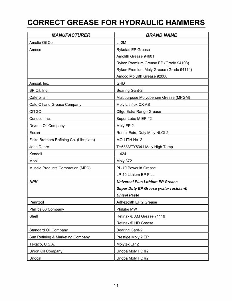
CORRECT GREASE The type of grease used is very important. NPK recommends a Lithium Base, Moly (Molybdenum Disulfide) or other surface protecting additives, EP (Extreme Pressure), NLGI #2 grease. A high drop point (500°F, 260°C) grease is desirable.
On the following page is a list of commonly available greases, by manufacturer and brand name that meet NPK’s recommendations. NPK does not endorse any one brand as being superior to another. If you or your customers use a brand not listed, please call the NPK Service Department at 800-225-4379.
11
CORRECT GREASE FOR HYDRAULIC HAMMERS
MANUFACTURER BRAND NAME Amalie Oil Co. LI-2M
Amoco Rykotac EP Grease
Amolith Grease 94601
Rykon Premium Grease EP (Grade 94108)
Rykon Premium Moly Grease (Grade 94114)
Amoco Molylith Grease 92006
Amsoil, Inc. GHD
BP Oil, Inc. Bearing Gard-2
Caterpillar Multipurpose Molydbenum Grease (MPGM)
Cato Oil and Grease Company Moly Lithflex CX AS
CITGO Citgo Extra Range Grease
Conoco, Inc. Super Lube M EP #2
Dryden Oil Company Moly EP 2
Exxon Ronex Extra Duty Moly NLGI 2
Fiske Brothers Refining Co. (Libriplate) MO-LITH No. 2
John Deere TY6333/TY6341 Moly High Temp
Kendall L-424
Mobil Moly 372
Muscle Products Corporation (MPC) PL-10 Powerlift Grease
LP-10 Lithium EP Plus
NPK Universal Plus Lithium EP Grease
Super Duty EP Grease (water resistant) Chisel Paste
Pennzoil Adhezolith EP 2 Grease
Phillips 66 Company Philube MW
Shell Retinax ® AM Grease 71119
Retinax ® HD Grease
Standard Oil Company Bearing Gard-2
Sun Refining & Marketing Company Prestige Moly 2 EP
Texaco, U.S.A. Molytex EP 2
Union Oil Company Unoba Moly HD #2
Unocal Unoba Moly HD #2

12
NPK HAMMER GREASE NPK now offers hammer grease specially formulated to meet severe job requirements. The grease is available in three different temperature ranges - 350°, 500°, and 2000°. All are compatible with Autolube systems. Universal Plus and Super Duty are lithium soap based products that resists washout and contain NPK-10 additive for surface protection in friction affected areas. Chisel Paste is an aluminum complex soap base with 12% graphite and copper additives for extreme operating conditions.
UNIVERSAL PLUS 350 deg
NPK PART NO.
14 OZ. CARTRIDGE G000-1010 120 LB. KEG G000-1020 35 LB. PAIL G000-1030 400 LB. DRUM G000-1040
SUPER DUTY
500 deg NPK
PART NO. 14 OZ. CARTRIDGE G000-1011 120 LB. KEG G000-1021 35 LB. PAIL G000-1031 400 LB. DRUM G000-1041
CHISEL PASTE
2000 deg NPK
PART NO. 14 OZ. CARTRIDGE G000-1050

13
CORRECT USE OF NPK TOOLS
APPLICATION OF DOWNFORCE TO THE TOOL When the hammer piston is accelerated by the gas pressure of the hammer, the gas pressure also generates a reaction force, or recoil, which tries to raise the hammer. To resist this reaction, the hammer must be held firmly against the material to be broken. This also ensures the most efficient transfer of energy from the tool to the material to be broken.
Apply downforce, lift the carrier 2 – 3” (50 – 75 mm).
Raise the front of the machine slightly by applying downforce on the demolition tool. Press the control lever or the foot pedal to start the NPK HYDRAULIC HAMMER. Applying excessive force to the hammer will raise the carrier too high and jolt the operator when the material breaks. Let the NPK HYDRAULIC HAMMER do the work.

14
CORRECT USE OF NPK TOOLS, CONTINUED
APPLICATION OF DOWNFORCE TO THE TOOL (CONTINUED) 1. CORRECT 2. INCORRECT
F: The direction of force from the
boom (the direction tangent to the arc of the boom).
P: Penetration direction of the demolition tool.
A: Fulcrum.
DO NOT USE BOOM DOWNFORCE WHEN SLANT HAMMERING. For the most efficient demolition, align the direction of force (F) from the boom with the penetration direction (P) of the tool. Note Fig. 2, applying boom downforce when the hammer is at an angle, decreases the transfer of energy from the piston to the rock and increases the bending forces at the fulcrum of the tool. This unnecessary added stress leads to the following problems: 1. Premature bushing wear and/or tool breakage 2. Breakage of tie rods 3. Breakage of bracket bolts When the tool binds or the working angle is incorrect, the sound of the hammer changes. Keep the boom direction of force in the same direction the tool is penetrating. Use the boom cylinder to preload the hammer (apply downpressure), and use the bucket and stick cylinders for alignment. Keep the tool tangent to the arc of the boom. See Figures 10A, 10B, and 10C on page 15. “A” = TANGENTAL DIRECTION “B” = ARC OF BOOM

15
CORRECT USE OF NPK TOOLS, CONTINUED
BENDING MOMENT GENERATION
FIG. 10A
Use proper positioning and proper cylinders when loading hammer against material.
FIG. 10B
FIG. 10C
Do not use boom downforce when slant hammering. Use bucket and stick cylinders to apply force to the tool in a straight line.

16
CORRECT USE OF NPK TOOLS, CONTINUED
BENDING MOMENT GENERATION (CONTINUED) If the hammer is operated at an angle (slant hammering) to the downforce (A) produced by the excavator, a bending load (B) is placed on the tool. As the tool is twisted in the tool holder, it is forced into excessive heavy contact with the upper (C) and lower (D) tool holder bushings. This causes severe galling of the tool and wears the tool bushings into an “egg” shape. Severe galling of the tool creates stress cracks which will shorten the life of the tool. Impact shock waves traveling down the tool become concentrated at the points of contact between the tool and tool bushings. Under severe conditions, this will cause the tool to break instantly, see pages 18 and 19. Do not operate the boom, stick, or bucket cylinders excessively while firing the hammer. Putting the tool into a binding load (A) or prying (B) with the tool will cause premature breakage of the tool. During operation, it may be necessary to move the hammer in a slight rocking motion (towards and away from the carrier) so that the powder build up around the tool tip can be relieved. DO NOT ROCK EXCESSIVELY!

17
TYPES AND APPLICATIONS OF TOOL Choose and use the tool that is most suited for the work. Using a tool not suited for the work not only reduces the working efficiency but may cause chipping, deformation, or other damage to the tool.
STANDARD TOOLS
TOOL TYPE SHAPE APPLICATIONS
CHISEL Crosscut (FX)
• Controlled breakage of concrete • Layered sedimentary rock
-trenching, oversize • General demolition • Cutting casting gates
MOIL (P)
• Concrete structures – columns, etc. • Soft material
BLUNT (E)
• Concrete slab, bridge decking • Oversize • Slag removal
CORE (PC)
• Hard rock • General demolition
*The crosscut (FX) tool cuts at right angle, or crosswise, to the stick and boom of the excavator.
ACCESSORY TOOLS
SPECIALTY TOOL SHAPE APPLICATIONS FROST CUTTER
Crosscut (SX) In-Line (SY)
• Edge of trenching • Frost cutting
ADAPTER TOOLS (use with Tamper Plate and Post/Pipe Drivers)
• For attachments listed below
TAMPER PLATE (use with adapter tool)
• Soil compaction • Driving sheeting
POST and PIPE DRIVERS (use with adapter tool)
• Driving guard rails • Driving fence posts

18
TOOL BREAKAGE Description of tool failures, causes, preventative measures, and application of warranty.
TOOL BREAKAGE DUE TO EXCESSIVE BENDING MOMENT If the tool is subjected to excessive bending moment caused by slant hammering or prying, the tool will break. Tool breaks will generally resemble one of the following examples:
A. Starting point of crack
that leads to breakage. B. Starting point of break. C. Starting point of break.
D. Sudden break from instant overload condition, (face will look very dull gray).
E. Galling
CHARACTERISTICS OF THE BROKEN SECTION
1. The starting point of a fatigue fracture is on the surface of the tool and located at the
front or rear side of the tool, with the hammer installed on the excavator and viewed from the cab.
2. The tool has galled areas on its surface. The galling initiates a surface crack from
which the fatigue fracture starts. The stress cracks, combined with bending loads and impact shock, can break the tool.
PREVENTATIVE MEASURES 1. Properly position the hammer so as not to develop a bending moment in the tool. 2. Apply sufficient grease to prevent the tool from developing cracks due to galling.
This will also assure longer tool bushing life. WARRANTY NPK Warranty does not apply to this type of failure.
19
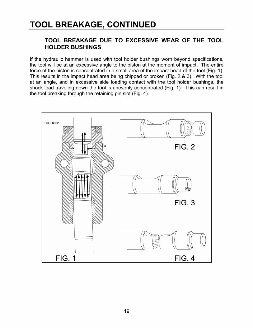
TOOL BREAKAGE, CONTINUED TOOL BREAKAGE DUE TO EXCESSIVE WEAR OF THE TOOL HOLDER BUSHINGS
If the hydraulic hammer is used with tool holder bushings worn beyond specifications, the tool will be at an excessive angle to the piston at the moment of impact. The entire force of the piston is concentrated in a small area of the impact head of the tool (Fig. 1). This results in the impact head area being chipped or broken (Fig. 2 & 3). With the tool at an angle, and in excessive side loading contact with the tool holder bushings, the shock load traveling down the tool is unevenly concentrated (Fig. 1). This can result in the tool breaking through the retaining pin slot (Fig. 4).

20
TOOL BREAKAGE, CONTINUED TOOL BREAKAGE DUE TO EXCESSIVE WEAR OF THE TOOL HOLDER BUSHINGS (CONTINUED)
PREVENTATIVE MEASURES
Replace the tool holder bushings when the clearance (C) reaches the maximum limit listed below. See the NPK Hydraulic Hammer Service Manual for maximum diameter (B) tool bushing (A) wear chart and minimum tool diameter (D).
MODEL MAXIMUM CLEARANCE (C) INCH (mm)
H06X, H08X 3/16 (5)
GH06, GH07, GH1, GH2, GH3, GH4, E200, E201, E202, E203, E204, E205, H1XA, H2XA
1/4 (6.5)
H3XA, H4XE, H4XL, H6XA
5/16 (8)
H7X, H8XA 11/32 (9)
GH6, GH7, GH9, GH10, E207, E208, E210A, E213, H10XB, H12X
3/8 (10)
GH12, GH15, GH18, E216, E220, E225, H16X, H20X
1/2 (13)
GH30, E240A, E260A, H30X
5/8 (16)
A. Tool Bushing B. Tool C. Clearance D. Tool Diameter
WARRANTY NPK Warranty does not cover tool failure caused by worn tool holder bushings.

21
TOOL BREAKAGE, CONTINUED
A. CHIPPING IN RETAINING PIN SLOT The tool may become chipped at the upper end of the retaining pin slot where it contacts the retaining pin. Free standing oversize rock may sometimes be broken with only a few hammer blows. If the operator does not stop hammering immediately, the tool will hit the retaining pin (blank hammering), and can chip the upper end of the retaining pin slot.
PREVENTATIVE MEASURES When the material is broken, stop operating the hammer immediately. Periodically check the tool and grind smooth any chipped areas to prevent stress cracks.
B. DEFORMATION OF THE RETAINING PIN SLOT SIDES The tool may become chipped or deformed in the area where it is in contact with the retaining pin. As the tool breaks material, it will try to follow any fracture lines in the material (Fig. 1). This causes a chisel point tool to twist in the tool holder. The retaining pin limits how far the tool can twist. If this happens often enough, the pin contact area of the tool can become chipped (Fig. 2) or deformed (Fig. 3).
FIG. 2
FIG. 1
FIG. 3
PREVENTATIVE MEASURES
The operator should place the chisel point in line with fractures or laminations in the material, not at an angle. The tool should be checked periodically for chipped areas. Grind smooth any chipped areas to prevent stress cracks in the tool.
22
TOOL BREAKAGE, CONTINUED
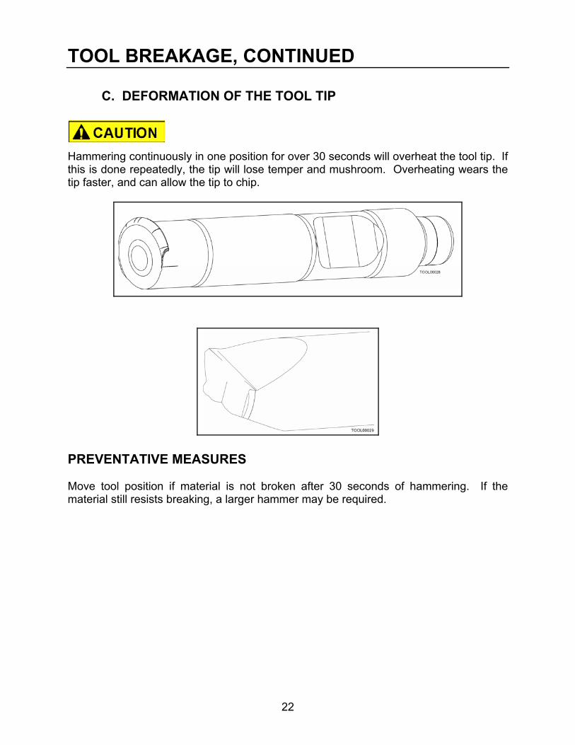
C. DEFORMATION OF THE TOOL TIP Hammering continuously in one position for over 30 seconds will overheat the tool tip. If this is done repeatedly, the tip will lose temper and mushroom. Overheating wears the tip faster, and can allow the tip to chip.
PREVENTATIVE MEASURES Move tool position if material is not broken after 30 seconds of hammering. If the material still resists breaking, a larger hammer may be required.

23
TOOL BREAKAGE, CONTINUED
D. CHIPPING OF A MOIL POINT TOOL TIP Moil (“P”) tools are intended for use on concrete or soft rock. The use of moil tools on hard rock may result in the point being chipped.
PREVENTATIVE MEASURES Use a chisel point (“FX” or “FY”) tool or a larger size hammer.
E. CHIPPING OF A CHISEL TOOL TIP Chisel tool tips may be chipped due to hammer being undersize for application. Overheating tool by hammering for more than 30 seconds in one spot can cause chipping.
PREVENTATIVE MEASURES Use correct size hammer for job conditions. Do not hammer for more than 30 seconds without moving hammer. WARRANTY NPK Warranty does not cover types A, B, C, D, & E problems.

24
TOOL BREAKAGE, CONTINUED TEMPERATURE RELATED TOOL PROBLEMS
LOW TEMPERATURE Metallic material becomes brittle in a low temperature environment and particularly sensitive to impact stress. PREVENTATIVE MEASURES
Warm the tool before starting to operate the hammer when temperature is below 32° F, (0° C). WARRANTY NPK Warranty does not cover this type of failure. EXCESSIVE SLANT HAMMERING When constant slant hammering is performed while using boom downforce, the tool may become deformed as shown in the picture below. HIGH TEMPERATURE When the tool is used in a high temperature environment, such as for slag removal from a furnace, the tool may be deformed as shown in the picture below. PREVENTATIVE MEASURES: Used compressed air to keep the tool cool enough not to deform.
WARRANTY NPK Warranty does not cover this type of problem.

25
TOOL BREAKAGE, CONTINUED
TOOL BREAKAGE DUE TO CORROSION Corrosion on the tool surface causes stress concentrations in the corroded area and a fatigue fracture can occur. These fractures, combined with impact stress can lead to tool breakage. PREVENTATIVE MEASURES After using the tool in salt water, after exposing it to a corrosive environment, or before long term storage, be sure to rinse with fresh water. Dry the tool and coat it with grease to protect it from corrosion. WARRANTY NPK Warranty does not cover this type of failure.
TOOL BREAKAGE DUE TO DEFECTIVE MATERIAL If metal fatigue originates from the interior, not the exterior, the material has some defect and fatigue will break the tool. The picture below illustrates the broken section. The starting point of breakage (A) is inside the tool, not on the surface.
WARRANTY NPK Warranty covers this type of failure.

26
CHISEL TOOL RESHARPENING
Worn chisel tools can be resharpened by machining according to the dimensions below.
DO NOT hardface or sharpen the tool point with a cutting torch! Resharpen only by milling or grinding, using sufficient coolant.
E SERIES
MODEL NO.
A inch mm
B inch mm
E200 .25 6.4 1.57 40 E201 .25 6.4 1.77 45 E202 .38 9.7 2.17 55 E203 .38 9.7 2.52 64 E204 .38 9.7 2.91 74 E205 .50 12.7 3.31 84 E207 .50 12.7 4.09 104 E208 .62 15.7 4.50 114 E210A .62 15.7 4.88 124 E213 .75 19 5.12 130 E216 .75 19 5.50 140 E220 .75 19 5.91 150 E225 .75 19 6.42 163 E240A .75 19 7.09 180 E260A .75 19 7.88 200
H SERIES
MODEL NO.
A inch mm
B inch mm
H06X - - - - H08X - - - - H1XA .38 9.7 2.12 53.8 H2XA .38 9.7 2.50 63.5 H3XA .38 9.7 3.00 76.2 H4XE/H4XL .50 12.7 3.25 82.3 H6XA .50 12.7 3.75 95.3 H7X .50 12.7 4.12 104.6H8XA .62 15.7 4.50 114.3H10XB .62 15.7 5.00 127.0H12X .75 19 5.38 136.7H16X .75 19 5.75 146.1H20X .75 19 6.12 155.4H30X 1.00 25.4 6.88 174.8
GH SERIES
MODEL NO.
A inch mm
B inch mm
GH06 .25 6.4 1.57 40 GH07 .25 6.4 1.77 45 GH1 .38 9.7 2.17 55 GH2 .38 9.7 2.52 64 GH3 .38 9.7 2.91 74 GH4 .50 12.7 3.31 84 GH6 .50 12.7 4.09 104 GH7 .62 15.7 4.50 114 GH9 .62 15.7 5.00 127 GH10 .75 19 5.12 125 GH12 .75 19 5.50 140 GH15 .75 19 5.91 150 GH18 .75 19 6.42 160 GH30 .75 19 7.09 180

27
STANDARD LENGTH FOR NPK TOOLS
L = Length of tool from top to bottom. W = Length of tool exposed from bottom of tool bushing to end of tool. D = Diameter of bearing surface of tool.
NEW TOOL DIAMETER (D)
MODEL INCH MM GH06 1.63 41.4 GH07 1.83 46.6 GH1 2.23 56.6 GH2 2.58 65.6 GH3 2.98 75.6 GH4 3.37 85.6 GH6 4.16 105.6 GH7 4.6 116 GH9 5.00 126 GH10 5.35 136 GH12 5.75 146 GH15 6.14 156 GH18 6.50 165 GH30 7.20 184
NEW TOOL DIAMETER (D)
MODEL INCH MM E200 1.63 41.4 E201 1.83 46.6 E202 2.23 56.6 E203 2.58 65.6 E204 2.98 75.6 E205 3.37 85.6 E207 4.16 105.6 E208 4.6 116 E210A 5.0 126 E213 5.4 136 E216 5.9 146 E220 6.2 156 E225 6.5 165 E240A 7.2 184 E260A 8.0 204
NOTE: Minimum tool length is determined by the depth of material penetration that is required.
NEW TOOL DIAMETER (D)
MODEL INCH MM
H06X 1.56 39.7 H08X 1.76 44.7 H1XA 2.23 56.7 H2XA 2.55 64.7 H3XA 2.94 74.7 H4XE/4XL 3.53 89.7 H6XA 3.77 95.7 H7X 4.16 105.7 H8XA 4.56 115.7 H10XB 4.95 125.7 H12X 5.34 135.7 H16X 5.74 145.7 H20X 6.13 155.7 H30X 6.88 174.7

28
TOOL IDENTIFICATION NPK demolition tools can be identified by the numbers found stamped in the retaining pin slot area. These numbers must be included in all warranty correspondences regarding a broken tool. Photos must also be included.

© Copyright 2007 NPK Construction Equipment, Inc. www.npkce.com H040-9600C.doc 08/07