hybrid positioning and sensor integration
TRANSCRIPT

14
Hybrid Positioning and Sensor Integration
Masahiko Nagai Asian Institute of Technology
Thailand
1. Introduction
Utilization of a mobile platform is important for effectively acquiring spatial data over a wide area (Zhao & Shibasaki, 2000). Although mobile mapping technology was developed in the late 1980s, the more recent availability of Global Positioning Systems (GPSs) and inertial measurement units (IMUs), the latter being a combination of accelerometers and gyroscopes, has made mobile mapping systems possible, particularly for aerial surveys and ground vehicle surveys (Manandhar & Shibasaki, 2002). Remote sensors—such as image sensors or laser scanners—are instruments that gather information about an object or area from a distance. Using these sensors for surveying and collecting information from mobile platforms has become a valuable means of disaster mapping, environmental monitoring, and urban mapping, amongst others.
Trajectory tracking of a mobile platform is considered part of directing the movement of a platform from one place on Earth to another. Although GPS gives excellent trajectory tracking performance, it is not adequate to use for mobile mapping in terms of its lack of attitude information and low data acquisition frequency. On the other hand, an IMU is a closed system that is used to detect attitude and position with high frequency.
An IMU exhibits position errors, called drift errors that tend to increase with time in an unrestrained manner. This degradation is due to errors in the initialization of an IMU and inertial sensor imperfections such as accelerometers bias and gyroscope drift. By mitigating this growth and bounding, the errors update the inertial system periodically by fixing external reference sources. The combination of GPS and IMU has become increasingly common as the characteristics of these two mobile positioning technologies complement each other. Firstly, an IMU provides continuous positioning drifts, whereas GPS measurements do not drift, but are not continuously available. Also, GPS, as external data, is used not only for position updates but also for error correction of inertial components such as attitude, heading, velocity, gyro bias, and accelerometer bias. However, the integration of IMU and GPS is restricted due to the cost of high quality inertial components.
To obtain both the wide area coverage of remote sensors and the high levels of detail and accuracy of ground surveying at low costs, a mobile mapping system has been developed in this research. All the measurement tools are mounted on a mobile platform to acquire detailed information. This mobile platform integrates and combines equipment such as digital cameras, a small and cheap laser scanner, an inexpensive IMU, GPS, and VMS (Velocity Measurement System). These sensors are integrated by a high-precision
www.intechopen.com

Global Navigation Satellite Systems – Signal, Theory and Applications
340
positioning system designed for moving environments and they carry out a key role in hybrid positioning.
In this paper direct geo-referencing is achieved automatically from a mobile platform with hybrid positioning by multi-sensor integration. Here, direct geo-referencing means geo-referencing that does not require that the ground control points accurately measure ground coordinate values. Data are acquired and digital surfaces are modeled using equipment which is mounted on a mobile platform. This allows objects to be automatically rendered in rich shapes and detailed textures.
2. System design for hybrid positioning and sensor integration
The key attributes of the design of the system are low cost, ease of use, and mobility (Parra & Angel, 2005). Firstly, it utilizes a small laser scanner, commercially available digital cameras, and a relatively inexpensive IMU such as FOG (Fiber Optic Gyro), not a high-performance and expensive IMU like Ring Laser Gyro. The IMU and other measurement tools used are much cheaper than those in existing aerial measurement systems, such as Applanix’s POS and Leica’s ADS40 (Cramera, 2006). Moreover, these low-cost instruments are easily available on the market. Recent technological advances have also led to low-cost sensors such as micro electro mechanical system (MEMS) gyros. For example, it is considered that MEMS gyros will supplant FOG in the near future and that the price will be approximately one-tenth of that of FOG. For this reason, FOG was selected for this paper in an attempt to improve a low-cost system for the future. Secondly, “mobility” here means the item is lightweight and simple to modify. Such sensors allow the system to be borne by a variety of platforms: UAV (Unmanned Aerial Vehicle), ground vehicles, humans, and others. These sensors are generally low-performance, but they are light and low-cost while still meeting the specifications. These handy sensors are improved by integrating their data.
2.1 Sensors
In this paper a laser scanner, digital cameras, an IMU, a GPS, and a VMS are used to find the precise trajectory of sensors and to construct a digital surface model as a mobile mapping system. To automatically construct such a model, it is necessary to develop a high-frequency positioning system to determine the movement of the sensors in details. The integration of GPS and IMU data is effective for high-accuracy positioning of a mobile platform. A 3D shape is acquired by the laser scanner as point cloud data and texture information is acquired by the digital cameras all from the same platform simultaneously. The sensors used in this paper are listed in Table 1.
2.2 Sensors’ calibration
Calibration of sensors is necessary for two reasons. One is to estimate the interior orientation parameter, such as lens distortion and focal length that are mechanical oriented parameters. The other reason calibration is necessary is to estimate exterior orientation parameters, such as a transformation matrix that has a relative position and attitude among sensors. All the sensors are tightly mounted on a platform and they have constant calibration parameters during the measurement. The purpose of calibration is chiefly to integrate all the sensors and positioning devices to a common single coordinating system, so that captured data can be integrated and expressed in terms of a common world coordinate system.
www.intechopen.com

Hybrid Positioning and Sensor Integration
341
Sensors Model Specifications
Digital Camera
Canon EOS 10D
3,072×2,048 pixels Focal length: 24.0mm Price: $1,500US Weight: 500g
IR Camera Tetracam ADC3
2,048×1,536 pixels Green, red, and NIR sensitivity with bands approximately equal to TM2, TM3, and TM4. Focal length: 10.0mm Price: $6,000US Weight: 500g
Laser Scanner
SICK LMS-291
Angular resolution: 0.25º Max. distance: 80m Accuracy (20m) : 10mm Price: $4,000US Weight: 4,000g
IMU Tamagawa Seiki Co., Ltd. TA7544
Fiber optic gyro Accuracy Angle: ±0.1° Angle velocity: ±0.05°/s Acceleration: ±0.002G Price: $20,000US Weight: 1,000g
GPS Ashtech G12
Accuracy differential: 30cm Velocity accuracy: 0.1(95%) Price: $4,000US Weight: 150g
VMS Ono Sokki Co., Ltd. LC-3110
Range: -120~+250 km/h Resolution: 10 mm/P Price: $13,000US Weight: 1.7kg
Table 1. List of sensors on mobile platform
2.2.1 Calibration of digital camera
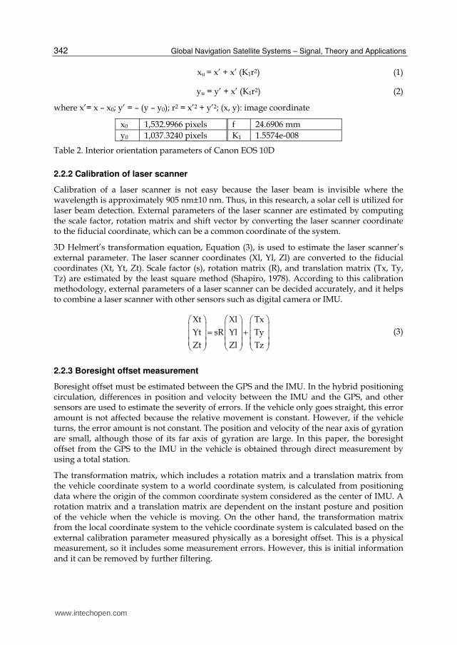
Initially, calibration of digital images is necessary due to the estimation of interior orientation parameters. Interior orientation is conducted to decide interior orientation parameters, principal point (x0, y0), focus length (f), and distortion coefficient (K1). Control points for camera calibration are taken as stereo images several times. Camera calibration is performed by the bundle adjustment using target control points. In order to estimate appropriate lens distortion for a digital camera, lens distortion mode is shown in Eq. (1) and Eq. (2). These equations consider only radial symmetric distortion (Kunii & Chikatsu, 2001). Image coordinate of (x, y) is corrected and transferred to new image coordinates of (xu, yu). Interior orientation parameters that are computed in this calibration for Canon EOS 10D are shown in Table 2.
www.intechopen.com
Global Navigation Satellite Systems – Signal, Theory and Applications
342
xu = x’ + x’ (K1r2) (1)
yu = y’ + x’ (K1r2) (2)
where x’= x – x0; y’ = – (y – y0); r2 = x’2 + y’2; (x, y): image coordinate
x0 1,532.9966 pixels f 24.6906 mm
y0 1,037.3240 pixels K1 1.5574e-008
Table 2. Interior orientation parameters of Canon EOS 10D
2.2.2 Calibration of laser scanner
Calibration of a laser scanner is not easy because the laser beam is invisible where the wavelength is approximately 905 nm±10 nm. Thus, in this research, a solar cell is utilized for laser beam detection. External parameters of the laser scanner are estimated by computing the scale factor, rotation matrix and shift vector by converting the laser scanner coordinate to the fiducial coordinate, which can be a common coordinate of the system.
3D Helmert’s transformation equation, Equation (3), is used to estimate the laser scanner’s external parameter. The laser scanner coordinates (Xl, Yl, Zl) are converted to the fiducial coordinates (Xt, Yt, Zt). Scale factor (s), rotation matrix (R), and translation matrix (Tx, Ty, Tz) are estimated by the least square method (Shapiro, 1978). According to this calibration methodology, external parameters of a laser scanner can be decided accurately, and it helps to combine a laser scanner with other sensors such as digital camera or IMU.
Xt Xl Tx
Yt sR Yl Ty
Zt Zl Tz
⎛ ⎞ ⎛ ⎞ ⎛ ⎞⎜ ⎟ ⎜ ⎟ ⎜ ⎟= +⎜ ⎟ ⎜ ⎟ ⎜ ⎟⎜ ⎟ ⎜ ⎟ ⎜ ⎟⎝ ⎠ ⎝ ⎠ ⎝ ⎠ (3)
2.2.3 Boresight offset measurement
Boresight offset must be estimated between the GPS and the IMU. In the hybrid positioning circulation, differences in position and velocity between the IMU and the GPS, and other sensors are used to estimate the severity of errors. If the vehicle only goes straight, this error amount is not affected because the relative movement is constant. However, if the vehicle turns, the error amount is not constant. The position and velocity of the near axis of gyration are small, although those of its far axis of gyration are large. In this paper, the boresight offset from the GPS to the IMU in the vehicle is obtained through direct measurement by using a total station.
The transformation matrix, which includes a rotation matrix and a translation matrix from the vehicle coordinate system to a world coordinate system, is calculated from positioning data where the origin of the common coordinate system considered as the center of IMU. A rotation matrix and a translation matrix are dependent on the instant posture and position of the vehicle when the vehicle is moving. On the other hand, the transformation matrix from the local coordinate system to the vehicle coordinate system is calculated based on the external calibration parameter measured physically as a boresight offset. This is a physical measurement, so it includes some measurement errors. However, this is initial information and it can be removed by further filtering.
www.intechopen.com

Hybrid Positioning and Sensor Integration
343
3. Multi sensor integration
Navigation is the continuous positioning which is the process of monitoring and controlling the movement of a vehicle from one place to another. Inertial navigation is the self-determination of the instantaneous position and other parameters of motion of a vehicle by measuring specific force, angular velocity, and time in a previously selected coordinate system. The basic concept is to determine the vehicle velocity and position by real time integration of governing differential equations.
Figure. 1 shows an overview of data processing of sensor integration from navigation as a hybrid positioning to mapping by direct geo-referencing with a laser scanner. In this paper, the following data are acquired and those data are integrated: base station GPS data, remote station GPS data, IMU data, digital images, and laser range data. Although the data are acquired in different frequencies, they are synchronized with each other by GPS time.
First, differential or kinematic GPS post processing is conducted. Second, the processed GPS data and the IMU data are integrated by a Kalman filter to estimate the sensor trajectory. The bundle block adjustment (BBA) of the digital images is then made to acquire geo-referenced images and exterior orientations with the support of GPS and IMU data, which are the sensor position and attitude, as an external aid. Also, VMS and other sensors can be considered as external aids if GPS accuracy is not enough to support IMU in urban areas. Finally, GPS data, IMU data, and the external aides are combined to regenerate high-precision and time-series sensor position and attitude. Finally, these hybrid positioning data are used for the geo-referencing of the laser range data and for the construction of a digital surface model as 3D point cloud data.
Post-processing GPS data
Integration of GPS/IMU by Kalman filtering
Bundle block adjustment to estimate sensor orientations
Geo referencing of laser range data
IMU data Digital images
(external aids)
Laser range data GPS data
Construction of DSM
Trajectory estimation by integration of GPS/IMU data and External Source
Pure navigation process
Fig. 1. Overview of data processing for multi sensor integration
4. Hybrid positioning
In general, IMUs exhibit position errors that tend to increase with time in an unbounded manner. This degradation occurs due to errors of initialization of IMUs and inertial sensor
www.intechopen.com

Global Navigation Satellite Systems – Signal, Theory and Applications
344
imperfections such as accelerometer bias and gyroscope drift. Hybrid positioning can mitigate the error by being updated periodically with external fixes, such as GPS, VMS, images, radio aids, or Doppler radar. Hybrid positioning is for finding the location of a mobile platform using or combining several different positioning technologies. The effect of fixing positions is that it allows for the reset or the correction of the position errors of the inertial system to the same level of accuracy inherent in the position fixing technology. The inertial system error grows at a rate equal to the velocity error. Therefore, external data is used not only for the position update but also the error correction of inertial components such as attitude, heading, velocity, gyro bias, and accelerometer bias. Furthermore, the error of the external data such as misalignment error, boresight error, and scale factor error is corrected in the same manner. Typical hybrid strapdown navigation is shown in Figure. 2.
X-gyro
Y-gyro
Z-gyro
X-accel.
Y-accel.
Z-accel.
Rotation Sensors
Translation Sensors
Δθ’s
ΔV’s
Strapdown Processing
and Navigation
Kalman filter
Observation Processing
External aids - GPS - Images - Speed meter - etc.
System Output - Position - Velocity - Acceleration - Attitude - Heading - Angular Rate - Application output
Fig. 2. Typical hybrid strap down navigation configuration
4.1 GPS and IMU data are integrated by Kalman filter
The Kalman filter can be used to optimally estimate the system states. One of the distinct advantages of the Kalman filter is that time varying coefficients are permitted in the model. With this filter, the final estimation is based on a combination of prediction and actual measurement. Figure 3 shows the pure navigation algorithm for deciding IMU attitude and IMU velocity step by step (Kumagai et al., 2002). Inertial navigation starts to define the initial attitude and heading based on the alignment of the system. It is processed and then it changes to the navigation mode. Over the years, the quality of IMUs has risen, but they are still affected by systemic errors. In this research, a GPS measurement is applied as an actual measurement to aid the IMU by correcting this huge drift error. With Kalman filtering, the sensor position and attitude are determined at 200 Hz.
Figure 4 shows the Kalman filter circulation diagram for the integration of the GPS and IMU data (Kumagai et al., 2000). Individual measurement equations and transition equations are
www.intechopen.com

Hybrid Positioning and Sensor Integration
345
selected, and covariance must be initialized in order to continue Kalman filtering circulation in response to the GPS data validation. The accuracy of the integration depends on the accuracy of the referenced GPS. In this case, it is approximately 30 cm.
Delta velocity Delta angle
Quaternion update
Euler matrix
generation
Coordinate transformation
IMU attitude
Velocity generation coriolis compensation gravity compensation
Relative rate generation
Latitude /longitude
wander azimuth generation
Earth rate generation
Torque rate generation IMU velocity
Initial attitude
Initial position initial wander
azimuth
Fig. 3. Pure navigation block diagram expressed roughly step by step
Update covariance matrix
Project ahead
Update filter estimate
Kalman gain generation
Measurement matrix calculation
Inertial estimate and its covariance New measurement
GPS on/off
Fig. 4. Kalman filter circulation
This research adopts the Kalman filter and the following steps are included, as shown in Figure 4.
1. Initialization of covariance value and first estimation of each variable 2. Inspection of GPS validity and selection of measurements equation
www.intechopen.com

Global Navigation Satellite Systems – Signal, Theory and Applications
346
3. Calculation of measurements 4. Calculation of the Kalman gain 5. Calculation of estimations 6. Calculation of next covariance 7. Updating of the covariance.
4.2 Bundle block adjustment (BBA) of digital images
The image exterior orientation is determined by the BBA for the mosaicked digital images where the BBA is a nonlinear least squares optimization method using the tie points of the inside block (Takagi & Shimoda, 2004). Bundle block configuration increases both the reliability and accuracy of object reconstruction. An object point is determined by the intersection of more than two images, which provides local redundancy for gross error detection and which consequently forms a better intersection geometry (Chen et al., 2003). Therefore, in this paper, the digital images are set to overlap by more than 50% in the forward direction, and by more than 30% on each side. The GPS and IMU data obtained in a previous step allow the automatic setting of tie points in overlapped images and reduce the time spent searching for tie points by limiting the search area based on the epipolar line. The epipolar line is the straight line of intersection between the epipolar plane and the image plane, and it is estimated by the sensor position and attitude, which is derived from GPS/IMU integration. It connects the image point in one image through the image point in the next image. Figure 5 shows an image orientation series with tie points that overlap each other. The image resolution is extremely high (approximately 1.5 cm), so it is easy to detect small gaps or cracks.
The accuracy of the image orientation (ba) is estimated by comparison with 20 control points (cp) as shown in Table 3. The average error of the plane is approximately 3 to 6 cm. The average error of the height is approximately 10 cm. That is, although the BBA is done automatically, the result is very accurate compared with the differential GPS or the GPS/IMU integration data, in which the average error is based on GPS accuracy. Moreover, the processing time is very short. Thus, the BBA’s results aid Kalman filtering by initializing the position and attitude in the next step to acquire a greater accurate trajectory.
Fig. 5. Image orientation with tie points
www.intechopen.com

Hybrid Positioning and Sensor Integration
347
Table 3. Accuracy of the image orientation
4.3 Hybrid positioning by multi sensor integration
The position and attitude of the sensors are dictated by the integration of the GPS and IMU data, as well as by the image orientations that are acquired from digital cameras or digital video cameras. One of the main objectives of this paper is to integrate inexpensive sensors into a high-precision positioning system. Integration of the GPS (which operates at 1 Hz) with the IMU (200 Hz) has to be made with Kalman filtering for the geo-referencing of laser range data with a frequency of 18 Hz. The positioning accuracy of the GPS/IMU integration data is based on GPS accuracy. On the other hand, both position and attitude can be estimated with very high accuracy using the BBA as image orientations. However, the images are not taken frequently; in this case every 10 seconds.
Therefore, the combination of the BBA and Kalman filtering is conducted to increase accuracy, as shown in Figure 6. The BBA results are assumed to be true position values. They provide initial attitude and heading without any IMU alignment. The IMU is initialized by Kalman filtering using the BBA result every 10 seconds to avoid a culmination of errors. That is, after every computation of the BBA, the IMU data and its errors are corrected. Figure 6 shows the strapdown navigation algorithm for the GPS/IMU integration and the BBA result. The combination of GPS, IMU, and images can be a hybrid positioning.
As a result of the multi sensor integration, the trajectory of the hybrid positioning can assure sufficient geo-referencing accuracy for the images. The trajectory of the digital camera can be representative of the trajectory of the platform because the GPS and IMU data are initialized by camera orientation. Their coordinate is fitted to the digital camera coordinate. Figure 7 shows the hybrid position as trajectories of GPS/IMU/images and GPS/IMU. The coordinate system is JGD2000 (Japan Geodetic Datum 2000). The black solid line is the combination of GPS/IMU/images, and the red solid line is the ordinary combination of
www.intechopen.com

Global Navigation Satellite Systems – Signal, Theory and Applications
348
GPS/IMU. On the one hand, with an ordinary GPS/IMU, the trajectory becomes notched because the position is revised forcibly by GPS due to drift error. The platform changes its attitude rapidly, especially in the corner, so the notched trajectory is very obvious. The drift error remains in the calculation until the alignment of IMU is complete. On the other hand, with GPS/IMU/images, the drift error of IMU is aligned by initialization from the bundle block adjustment. Moreover, the trajectory is very smooth in the corner.
Kalman filter
1Hz
GPS
+ ‐
+ ‐
GPS Velocity
GPS Position
IMU Velocity
IMU Position
Velocity Error Position Error
1Hz
Hybrid position and attitude
200 Hz
IMU
200Hz
Camera
Attitude 0.1Hz
Image orientation (BBA) Position
Fig. 6. Strapdown navigation diagram with images
GPS/IMU/images GPS/IMU
X 譆m譙 JGD2000
11220 11210 11200 11190 11180 11170 11160 11150 11140 11130
25670
25665
25660
25655
25650
25645
25640
25635
25630
Y 譆m譙
JGD
2000
Fig. 7. Hybrid position
4.4 Evaluation of hybrid positioning
Trajectory tracking by ordinary GPS/IMU integration is compared to the combining of GPS/IMU and continual digital images, in order to validate this combination. Figure 8 shows
www.intechopen.com

Hybrid Positioning and Sensor Integration
349
the yaw angles of these two methods; the black solid line is the combination of GPS/IMU/images, and the red solid line is the ordinary integration of GPS/IMU. In the case of the GPS/IMU/images combination, an accurate azimuth angle, as a yaw angle, is recorded from the BBA. Thus, the yaw angle is then accurate from the beginning of the measurement. On the other hand, in the ordinary combination of GPS/IMU, the Kalman filter gradually estimates the state of a system from measurements which contain random
GPS/IMU/images GPS/IMU
-50
0
50
100
150
200
120
358
596
834
1072
1310
1548
1786
2024
2262
2500
2738
2976
3214
3452
3690
3928
4166
4404
4642
4880
time 譆1/20sec譙
Yaw 譆
°譙
Fig. 8. Comparison of Yaw angle
GPS/IMU/images GPS/IMU
time 譆1/20sec譙
Pit
ch 譆°譙
-8
-4
0
4
8
1 153
305
457
609
761
913
1065
1217
1369
1521
1673
1825
1977
2129
2281
2433
2585
2737
2889
time譆1/20sec譙
Ro
ll 譆°譙
-4
0
4
8
1 153
305
457
609
761
913
1065
1217
1369
1521
1673
1825
1977
2129
2281
2433
2585
2737
2889
Fig. 9. Comparison of Roll and Pitch angle
www.intechopen.com

Global Navigation Satellite Systems – Signal, Theory and Applications
350
errors. That is, error estimation is not enough at the beginning, and the yaw angle gradually improves. For that reason, in the case of ordinary GPS/IMU, it is necessary to have the system alignment before the measurement in order to estimate an accurate azimuth angle. Therefore, in this proposed method, the system alignment is not required. Figure 9 shows the roll and the pitch angle of the two methods. The phenomenon of the error for the roll and pitch angle is the same as the yaw angle.
5. Experiment
In order to appraise the characteristics and performance of the proposed algorithm, two experiments are conducted by using a UAV (Unmanned Aerial Vehicle) and ground vehicle (a car) as a platform. In the case of the UAV, images are used for external aid, whereas VMS is used as an external aid in the case of the ground vehicle.
5.1 UAV (Unmanned Aerial Vehicle) based mapping system
A UAV based mapping system is developed to obtain both the wide-area coverage of remote sensors and the high levels of detail and accuracy of ground surveying, at low cost. All the measurement tools are mounted under the UAV, which resembles a helicopter, to acquire detailed information from low altitudes, unlike high altitude systems in satellites or airplanes. The survey is conducted from the sky, but the resolution and accuracy are equal to those of ground surveying. Moreover, the UAV can acquire data easily as well as safely.
In this paper, all of the measurement tools are mounted under the UAV, which is a helicopter-like model RPH2 made by Fuji Heavy Industries, Ltd., and shown in Figure 10. All the sensors are mounted tightly to the bottom of the fuselage. The RPH2 is 4.1m long, 1.3m wide and 1.8m high. Table 4 shows its main specifications.
GPS (Ashtech G12)
PC
IMU
(Tamagawa Seiki TA7544)
Digital Camera (Canon EOS-10D)
Laser Scanner (SICK LMS-291)
Fig. 10. UAV, model RPH2 made by Fuji Heavy Industries, Ltd.
As shown in Table 4, the RPH2 is a large UAV; however, it is considered a platform for the experimental development of a multi-sensor integration algorithm. The RPH2 has a large payload capacity; thus, it can carry large numbers of sensors, control PCs, and a large battery. After the algorithm is developed by a large platform, a small UAV system is implemented using selected inexpensive sensors for certain observation targets.
www.intechopen.com

Hybrid Positioning and Sensor Integration
351
There are several advantages to utilizing a UAV. One of the most important advantages is that it is unmanned and therefore can fly over dangerous zones. This advantage suits the purpose of direct geo-referencing in this study. Direct geo-referencing does not require that ground control points have accurately measured ground coordinate values. In dangerous zones, it is impossible to set control points, unlike the case in normal aerial surveys. The addition of this direct geo-referencing method from a UAV could be an ideal tool for monitoring dangerous situations. Therefore, this UAV-based mapping system is perfectly suited for disaster areas such as landslides and floods, and for other applications such as river monitoring.
Weight 330kg
Payload 100kg
Motor 83.5 hp
Main rotor 2 rotors, diameter 4.8m
Tail rotor 2 rotors, diameter 0.8m
Operational 3km or more
Flight time 1 hour
Ceiling 2,000m
Table 4. Specification of RPH2
5.1.1 UAV based system
All the sensors are tightly mounted under the UAV to ensure that they have a constant geometric relationship during the measurement. The digital cameras and the laser scanner are calibrated to estimate the relative position and attitude. Moreover, all sensors are controlled by a laptop PC and are synchronized by GPS time, one pulse per second. Finally the sensors are set, as shown in Figure 10.
5.1.2 Digital 3D modeling
During measurement, the platform, including all of the sensors, is continuously changing its position and attitude with respect to time. For direct geo-referencing of laser range data, the hybrid positioning data are used. There are two coordinate systems; the laser scanner and the hybrid positioning, WGS84 (World Geodetic System 1984) based on GPS and the BBA data. It is necessary to transform the laser scanner coordinate into the WGS84 coordinate by geo-referencing. Geo-referencing of the laser range data is determined by the 3D Helmert’s transformation, which is computed by the rotation matrix and translation matrix with the hybrid positioning data and calibration parameters as offset values, as shown in Equation (3), for calibration by the laser scanner. The offset values from the laser scanner to the digital cameras in the body frame are already obtained by the sensor calibration. Geo-referencing of laser range data and images is done directly.
Figure 11 shows the 3D point cloud data that are directly geo-referenced by the hybrid IMU data. In this research, the WGS84 is used as the base coordinate system for the 3D point cloud data. The UAV-based system in this research utilized a landslide survey by
www.intechopen.com

Global Navigation Satellite Systems – Signal, Theory and Applications
352
reconstructing a digital surface model. A digital camera and a laser scanner were mounted on a UAV to acquire detailed information from low altitude. The surveying is carried out from the sky, but the resolution and accuracy are the same level as a ground survey. Because of the utilization of a UAV, the data of the landslide site can be easily acquired collectively with safety and mobility. This new survey can be an intermediate method between aerial surveys and ground surveys.
Fig. 11. 3D point cloud model
5.2 Ground vehicle based mapping system
Understanding road environments has become increasing more important in recent years due to a wide range of applications, such as intelligent vehicles, driving assistance and sign inventory systems or route guidance systems for navigation assistance. For drivers, traffic signs/signals provide crucial information for safety and smooth driving; thus, they play an important role in all kinds of driver support systems. Much work on traffic signal/sign detection and recognition has been done in recent years and sensor systems now consist of three different types of sensors, including laser scanners for measuring object geometry, digital cameras for capturing scene texture, and the moving platform equipped with a GPS/IMU/VMS based hybrid positioning system.
5.2.1 Ground vehicle based system
Figure 12 shows the ground vehicle based system where all sensors are mounted on the roof of the vehicle. Two of the laser range scanners are mounted on the back and scan the horizontal plane. VMS is also mounted and is used to assist the navigation unit to locate vehicle positions when the GPS signal is unavailable. The other two laser scanners are placed on the front and rear of the vehicle’s roof. The front one scans with an elevation of about 30 degrees to capture the front scene, especially the important urban spatial objects that assist navigation. For data measurement, all the sensors are under control of the vehicle-borne computers and synchronized by a GPS clock.
www.intechopen.com

Hybrid Positioning and Sensor Integration
353
The navigation units used in the sensor system are composed of a DGPS, an IMU (FOG) and a VMS (Velocity Measurement System). The DGPS is responsible for measuring the vehicle’s position using a satellite signal. The IMU, consisting of accelerometers and gyroscopes, measures the acceleration and direction changes of the vehicle, while VMS is in charge of measuring the vehicle’s velocity with high accuracy. The combination of GPS/IMU/VMS is complementary as the velocity from VMS, and the acceleration and direction changes from IMU can be used to locate a vehicle’s position when the GPS signal is unavailable. Moreover, the GPS can be used to rectify the output of IMU. VMS data is more accurate when compared with DGPS; thus, the estimation of VMS errors becomes possible when DGPS is valid. Therefore, it is possible to acquire a more precise positioning in the pure PDOP condition like an urban operation by means of blending VMS data. The strapdown navigation diagram for a ground vehicle mapping system is shown in Figure 13. The Kalman filter is processed every 10 seconds.
Fig. 12. Ground vehicle based system
IMU 200Hz
10 Hz
Hybrid
IMU
Speed
RTK-GPS + ‐
+ ‐
GPS position
GPS velocity
IMU position
IMU velocity
Position error Velocity error
1Hz
200Hz
10Hz
VMS
Kalman filter
Fig. 13. Strapdown navigation diagram with VMS
www.intechopen.com

Global Navigation Satellite Systems – Signal, Theory and Applications
354
5.2.2 Object extraction
Figure 14 shows the point cloud acquired by the laser scanner, which is geo referenced with hybrid positioning data and contains not only traffic signs/signals but also the surroundings (vegetation and buildings) beyond the road. Object segmentation and feature extraction of important objects, such as traffic signs/signals, are conducted. This is most common especially after most redundant range points have been detached from the point cloud after boundary extraction. Range points represent the geographic information of all the objects in the form of 3D discrete coordinates, which have no description of attribute and there is no topological relation among the data points. However, spatial features exist which can be used for object segmentation. It is clear that the traffic sign/signal has a strong linear feature after being projected onto the horizontal plane, while points belonging to other spatial objects (such as trees) are scattered on the horizontal plane without a dominant direction. This spatial feature can be utilized for segmentation.
Fig. 14. 3D point cloud data from vehicle based system
6. Validation
In this mobile mapping system, multiple sensors are integrated, thus making it difficult to point out the origins of errors for positioning. Therefore, accuracy of positioning is assessed by an ordinary survey method, the result of which is compared with a digital surface model and control points from the oriented images; the accuracy is 3 to 10 cm, as shown in Table. 3. Those control points are considered as true values and selected feature points such as object corners, which can recognize both images and a digital surface model (DSM). As a result, the average error of the digital surface model is approximately 10 to 30 cm, as shown in Table. 5.
For this validation, DSM has been reconstructed and geo-referenced by using a hybrid position. The laser range data are acquired 50 m away from the object and the scan angler
www.intechopen.com

Hybrid Positioning and Sensor Integration
355
resolution is 0.25°; that is, the density of 3D laser points is approximately 20 cm per point. After comparing the mapping accuracy with the laser point density, it was found that the accuracy is good enough for mapping DSM. Therefore, the accuracy of hybrid positioning including their attitude is considered approximately 10 to 30 cm.
Ave. Error
Error Error Error
DSM DSM DSM
Ground Control point
No綌 譆肫譙 譆胗譙 譆胘譙 譆肫譙 譆胗譙 譆胘譙 譆肫譙 譆胗譙 譆胘譙
緱 綋緱緱緱繢縑綌繢繇繇 綋緹縕縠縈緫綌緹縕縈 縑緹綌繇縕縕 綋緱緱緱繢縑綌縠繮縠 綋緹縕縠縈緫綌繢縈縠 縑緹綌繮緱縕 緫綌緱繢緱 緫綌縕繢縈 緫綌緱縠緫
緹 綋緱緱緱繢縕綌縑繇緱 綋緹縕縠緹緹綌繇緹繇 縑緹綌繮縕緹 綋緱緱緱繢縕綌縕縕繇 綋緹縕縠緹緹綌繇繢繮 縑緹綌繮繇緱 緫綌緫繢縠 緫綌緫縠緹 緫綌緫緱繮
縈 綋緱緱緱縠繇綌縠緫縈 綋緹縕縠繇緫綌縑繇縑 縑緹綌縈繮緱 綋緱緱緱縠繢綌緹繢緹 綋緹縕縠繇緫綌縈緱緹 縑緹綌縑緫縠 緫綌縠繇繮 緫綌緱縠緹 緫綌緫緱縕
縑 綋緱緱緱繇繇綌緱緫繇 綋緹縕縠縈縑綌繇緹緱 縑緹綌繇緫縑 綋緱緱緱繇繇綌緹縠緹 綋緹縕縠縈縑綌繮緱繢 縑緹綌縕緹縈 緫綌緱縕縕 緫綌緱繮繇 緫綌緱繢緱
縕 綋緱緱緱縕緹綌繢縠縠 綋緹縕縠縑緱綌繇縕縈 縑緹綌緫緹繮 綋緱緱緱縕緹綌緱繇緹 綋緹縕縠縑緱綌緫縈縠 縑緹綌緫繇緱 緫綌縠繮縑 緫綌繇緱繇 緫綌緫縑緹
縠 綋緱緱緱繇縠綌縕緱緱 綋緹縕縠緹縕綌縕繇緱 縑緹綌繢緹縑 綋緱緱緱繇縠綌縑縠繇 綋緹縕縠緹縕綌縑緹縠 縑緹綌繇縠繇 緫綌緫縑縑 緫綌緱縑縕 緫綌緫縕繇
繇 綋緱緱緱縕縈綌繮緱緱 綋緹縕縠縑縈綌繢緹縈 縑緹綌縕縈縑 綋緱緱緱縕縑綌縈繇縕 綋緹縕縠縑縈綌緫縑緱 縑緹綌緫繇縕 緫綌縑縠縑 緫綌繇繢緹 緫綌縑縕繮
繢 綋緱緱緱縕緫綌縕縠縑 綋緹縕縠縈緱綌繇緹縑 縑緹綌縈縑緫 綋緱緱緱縕緫綌繢繢繇 綋緹縕縠縈緱綌繢縠繮 縑緹綌緹繮縠 緫綌縈緹縈 緫綌緱縑縕 緫綌緫縑縑
繮 綋緱緱緱繇縠綌繇繇緱 綋緹縕縠縈縕綌縈縑縑 縑縈綌繮繮緹 綋緱緱緱繇縠綌縈繮縑 綋緹縕縠縈縕綌縈緫繢 縑縑綌緫繢緹 緫綌縈繇繇 緫綌緫縈縠 緫綌緫繮緫
緱緫 綋緱緱緱繢縠綌縠縠縠 綋緹縕縠縈緱綌縠縕繇 縑縑綌緹繢繮 綋緱緱緱繢縠綌縑緱繇 綋緹縕縠縈緱綌繢繢繢 縑縑綌緹緫緹 緫綌緹縑繮 緫綌緹縈緱 緫綌緫繢繇
緫綌縈緹縕 緫綌縈緫縠 緫綌緱緱縕
Unit: m
Table 5. Positioning accuracy assessment from DSM
7. Conclusion
In this paper, robust trajectory tracking by hybrid positioning was developed and a digital surface model was reconstructed with multi–sensor integration using entirely inexpensive sensors, such as a small laser scanner, digital cameras, an inexpensive IMU, a GPS, and a VMS. A new method of direct geo-referencing was proposed for laser range data and images by combining a Kalman filter and the BBA or VMS. Because the result of BBA avoids the accumulation of drift errors in the Kalman filtering, the geo-referenced laser range data and the images were automatically overlapped properly in the common world coordinate system. Hybrid positioning data is acquired by using or combining several different positioning technologies. Since this paper focused on how to integrate the sensors into a mobile platform, all the sensors and instruments were assembled and mounted under a mobile platform such as a UAV or ground vehicle in this experiment. Finally, the precise trajectory, including attitude of the sensors, was computed as the hybrid positioning for direct geo-referencing of a laser scanner. The hybrid positioning data is used to reconstruct digital surface models.
8. References
Zhao, H. & Shibasaki, R. (2000). Reconstruction of Textured Urban 3D Model by Ground-Based
Laser Range and CCD Images, IEICE Trans. Inf.&Syst., vol.E83-D, No.7 Manandhar, D. & Shibasaki, R. (2002). Auto-Extraction of Urban Features from Vehicle-Borne
Laser Data, ISPRS, GeoSpatial Theory, Processing and Application, Ottawa
www.intechopen.com

Global Navigation Satellite Systems – Signal, Theory and Applications
356
Parra, S. & Angel, J. (2005). Low cost navigation system for UAV's, Aerospace Science and Technology, Issue 6, Volume 9, pp.504-516
Cramera, M. (2006). The ADS40 Vaihingen/Enz geometric performance test, ISPRS Journal of Photogrammetry and Remote Sensing, Volume 60, Issue 6, pp. 363-374
Kunii, Y. & Chikatsu, H. (2001). Application of 3-Million Pixel Armature Camera for the 3D Modeling of Historical Structures, Asian Journal of GEOINFORMATICS Vol. 2, No. 1, pp. 39-48
Shapiro, R. (1978). Direct linear transformation method for three-dimensional cinematography, Res. Quart. 49, pp. 197-205
Kumagai, H., Kubo, Y., Kihara, M. & Sugimoto, S. (2002). DGPS/INS/VMS Integration for High Accuracy Land-Vehicle Positioning, Journal of the Japan Society of Photogrammetry and Remote Sensing, vol.41, no.4 pp. 77-84
Kuamgai, H., Kindo, T., Kubo, Y. & Sugimoto, S. (2000). DGPS/INS/VMS Integration for High Accuracy Land-Vehicle Positioning, Proceedings of the Institute of Navigation, GPS-2000, Salt Lake
Takagi, M. & Shimoda, H. (2004). Handbook of image analysis, University of Tokyo Press Chen, T., Shibasaki, R. & Murai, S. (2003). Development and Calibration of the Airborne Three-
Line Scanner (TLS) Imaging System, Journal of the American Society for Photogrammetry and Remote Sensing PE&RS, vol.69, No.1,pp. 71-78
www.intechopen.com

Global Navigation Satellite Systems: Signal, Theory andApplicationsEdited by Prof. Shuanggen Jin
ISBN 978-953-307-843-4Hard cover, 426 pagesPublisher InTechPublished online 03, February, 2012Published in print edition February, 2012
InTech EuropeUniversity Campus STeP Ri Slavka Krautzeka 83/A 51000 Rijeka, Croatia Phone: +385 (51) 770 447 Fax: +385 (51) 686 166www.intechopen.com
InTech ChinaUnit 405, Office Block, Hotel Equatorial Shanghai No.65, Yan An Road (West), Shanghai, 200040, China
Phone: +86-21-62489820 Fax: +86-21-62489821
Global Navigation Satellite System (GNSS) plays a key role in high precision navigation, positioning, timing,and scientific questions related to precise positioning. This is a highly precise, continuous, all-weather, andreal-time technique. The book is devoted to presenting recent results and developments in GNSS theory,system, signal, receiver, method, and errors sources, such as multipath effects and atmospheric delays.Furthermore, varied GNSS applications are demonstrated and evaluated in hybrid positioning, multi-sensorintegration, height system, Network Real Time Kinematic (NRTK), wheeled robots, and status and engineeringsurveying. This book provides a good reference for GNSS designers, engineers, and scientists, as well as theuser market.
How to referenceIn order to correctly reference this scholarly work, feel free to copy and paste the following:
Masahiko Nagai (2012). Hybrid Positioning and Sensor Integration, Global Navigation Satellite Systems:Signal, Theory and Applications, Prof. Shuanggen Jin (Ed.), ISBN: 978-953-307-843-4, InTech, Available from:http://www.intechopen.com/books/global-navigation-satellite-systems-signal-theory-and-applications/hybrid-positioning-and-sensor-integration

© 2012 The Author(s). Licensee IntechOpen. This is an open access articledistributed under the terms of the Creative Commons Attribution 3.0License, which permits unrestricted use, distribution, and reproduction inany medium, provided the original work is properly cited.