hybrid electric propulsion for military vehicles · a hybrid electric vehicle (hev) is basically a...
TRANSCRIPT
FFI-rapport 2008/01220
Hybrid electric propulsion for military vehicles
Overview and status of the technology
Per Dalsjø
Norwegian Defence Research Establishment (FFI)
24 June 2008

FFI-rapport 2008/01220
1019
P: ISBN 978-82-464-1395-2
E: ISBN 978-82-464-1394-5
Keywords
Hybrid-elektrisk fremdrift
Kjøretøyteknologi
Elektrisk motor
Batteri
Approved by
Einar Østevold Project manager
Johnny Bardal Director
2 FFI-rapport 2008/01220
English summary In the civilian market the hybrid electric vehicle (HEV) is receiving increasing attention due to its reduced fuel consumption. The HEV is basically a combination of the common internal combustion engine (ICE) powered vehicle and the battery powered electric vehicle (EV). The purpose of the electric motor and battery is to shift the operation of the ICE closer to its optimum operating condition, and enable regenerative braking.
There is also a great interest in HEV technology for military vehicles. An important advantage is the possibility to generate additional onboard electric power. This is important in meeting the ever increasing demand for electric power onboard modern military vehicles. Other potential advantages are improved fuel economy, extended silent watch capability, silent mobility, a modular vehicle design and reduced life cycle cost (LCC).
However, there are important technical challenges that need to be solved before we will see the successful fielding of a mass produced military HEV. A number of military HEVs have been successfully demonstrated, but there are still important limitation related to key technologies such as electric motors, power electronics and energy storage systems (e.g. batteries). The maturity of the technology, depends on the vehicle type (role, weight, tracked or wheeled etc) and the HEV drivetrain architecture opted for (series, parallel etc.)
This report aims to describe the HEV technology and the advantages and technical challenges of different key technologies. How the technology affects the overall vehicle design, is also discussed. In doing so, the different key technologies are described in some detail. The different programs and efforts related to the development of military HEVs are also presented.
The first military HEV is expected to be fielded in approximately 5-7 years. Based on the maturity of the technology this will likely be a wheeled multirole vehicle, weighing 5.000-10.000 kg, implementing a parallel drivetrain. This claim is however based on the assumption that an HEV demonstrator is selected, in June 2008, to participate in the demonstration phase of the US Joint Light Tactical Vehicle (JLTV) program.
The US Future Combat System (FCS) program is committed to the development of a series drivetrain technology for tracked vehicles. If the FCS program is completed as planned, a family of tracked HEVs will be fielded in approximately 7 years.
In recent years, military vehicle requirements have changed considerably. This is likely to continue in the future, with features such as flexibility, transportability and cost becoming increasingly important. To meet these requirements, it is expected that HEV technology will become important, due to the features and advantages enabled by the technology.
FFI-rapport 2008/01220 3
Sammendrag I det sivile markedet er det økende oppmerksomhet rundt hybrid-elektriske (HE) biler pga redusert drivstofforbruk. En HE-bil er kort sagt en kombinasjon av en vanlig bil, drevet av en forbrenningsmotor, og en elektrisk bil med batterier. Meningen med elektromotoren og batteriene er å forflytte arbeidsområdet for forbrenningsmotoren nærmere dens optimale arbeidsområde, og gjøre det mulig å gjenvinne energi ved å benytte bremser som generer elektrisk energi.
Det er også stor interesse rundt HE-teknologi for militære kjøretøy. En viktig fordel er muligheten for å generere en større mengde elektrisk effekt i kjøretøyet. Dette er viktig fordi strømbehovet i moderne militære kjøretøy er stadig økende. Andre potensielle fordeler er redusert drivstoff-forbruk, systemer i kjøretøyet kan benyttes over tid uten å starte hovedmotoren (”silent watch” / ”silent operation”), stillegående elektrisk fremdrift (”silent mobility”), et modulært kjøretøydesign og reduserte levetidskostnader.
Det er imidlertid viktige teknisk utfordringer som må løses før vi vil se introduksjonen av et masseprodusert militært HE-kjøretøy. En rekke militære HE-kjøretøyer har gjennomført vellykkede demonstrasjoner, men disse har allikevel hatt viktige begrensninger som er relatert til kjerneteknologier som elektromotorer, høyeffekt elektronikk og energilagringssystemer (f.eks. batteri). Teknologiens modenhet er imidlertid avhengig av kjøretøytype (rolle, vekt, beltegående eller hjulgående osv) og HE-drivlinjen som velges (serie, parallell osv).
Hensikten med denne rapporten er å beskrive teknologien og fordelen og de tekniske utfordringene relatert til de forskjellige kjerneteknologiene. Hvordan teknologien påvirker utformingen av kjøretøyet generelt, vil også bli diskutert. For å gjøre dette er noen kjerneteknologier beskrevet i noe detalj. Forskjellige programmer som er relevante for utviklingen av militære HE-kjøretøy, vil også bli presentert.
Det første militære HE-kjøretøyet vil trolig bli lansert om 5-7 år. Dette vil sannsynligvis være et hjulgående multirolle-kjøretøy som veier 5.000-10.000 kg, med en såkalt parallell-drivlinje. Denne uttalelsen er imidlertid basert på at et HE-kjøretøy blir valgt, i juni 2008, til å delta i demonstrasjonsfasen i det amerikanske Joint Light Tactical Vehicle (JLTV) -programmet.
Det amerikanske Future Combat System (FCS) -programmet utvikler en serie-drivlinjeteknologi for beltegående kjøretøy. Hvis FCS-programmet fullføres i henhold til planen, vil en familie av beltegående HE-kjøretøy bli lansert om omtrent 7 år.
I de siste årene, har kravene til militære kjøretøy forandret seg. Dette vil trolig fortsette i fremtiden, hvor fleksibilitet, muligheten for lufttransport og levetidskostnader blir viktige. For å tilfredsstille disse kravene, antas HE-teknologien å bli viktig pga egenskapene og fordelene som teknologien muliggjør.
4 FFI-rapport 2008/01220
Contents
1 Introduction 9 1.1 Objective and Structure of the Report 10
2 Motivation and Technical challenges 12 2.1 Potential Advantages 12 2.1.1 Increased Available Onboard Electric Power 12 2.1.2 Improved Fuel Economy 12 2.1.3 Silent Watch and Silent Mobility 13 2.1.4 Vehicle Design and Architecture 14 2.2 Technical Challenges 15 2.2.1 Vehicle Design and Architecture 15 2.2.2 Electric Motors 16 2.2.3 Power Electronics 16 2.2.4 Energy Storage 17
3 Vehicle Fundamentals 18 3.1 General Description of Forces Acting on a Vehicle 18 3.2 Vehicle Characteristics 19 3.2.1 Power Plant Characteristics 19 3.2.2 Transmission Characteristics 20 3.3 Architecture of Mechanical Drivetrains 22 3.3.1 Wheeled Vehicles 22 3.3.2 Tracked Vehicles 23
4 HEV Drivetrains 25 4.1 Series HEV 25 4.1.1 Advantages 27 4.1.2 Disadvantages 28 4.2 Parallel HEV 28 4.2.1 Mechanical Coupling 29 4.2.2 Advantages 31 4.2.3 Disadvantages 32 4.3 Series-Parallel HEV 32
5 Electric Motor Drives 33 5.1 Introduction 33 5.2 DC Motor 36 5.2.1 Inverter Control 37
FFI-rapport 2008/01220 5
5.2.2 Multi Quadrant Operation 37 5.3 Induction Motor 38 5.3.1 Constant Volt/ Hertz Control 39 5.3.2 Field Orientation Control 40 5.4 Permanent Magnetic Brush-Less DC Motor Drives 42 5.4.1 Permanent Magnet Materials 43 5.4.2 Control and Performance Analysis of BLDC Motors 44 5.4.3 Sensorless Control 45 5.5 Switched Reluctance Motor Drives 45 5.5.1 Control of an SRM 47 5.5.2 Regenerative Braking 47 5.5.3 Sensorless Control 48 5.6 In-hub Electric Motors 48 5.7 Comparison of Electric Motor Drives 49
6 Power Electronics 50 6.1 Wide Bandgap Semiconductors 51
7 Energy Storage and Management 52 7.1 Batteries 52 7.2 Ultra-capacitors 55 7.3 Flywheel Energy Storage 56 7.4 Hybrid Energy Storage 56
8 Military HEV Programs and Efforts 58 8.1 Vehicle Development Programs Aiming to Meet Tomorrow’s Challenges 58 8.1.1 Future Combat Systems (FCS) 58 8.1.2 Joint Light Tactical Vehicle (JLTV) 59 8.1.3 Future Rapid Effects System (FRES) 59 8.1.4 Splitterskyddad EnhetsPlatform (SEP) 59 8.2 Task Groups Related to Military HEV Technology Evaluation and
Standardization 60 8.2.1 Combat Hybrid Power System Component Technologies 60 8.2.2 AVT-047 All Electric Combat Vehicles (AECV) for Future Applications 60 8.2.3 AVT-106 Hybrid Vehicle Rating Criteria 61 8.2.4 Hybrid Electric Vehicle Experimentation and Assessment (HEVEA) 61 8.3 Overview of Military HEV Demonstrators 62 8.3.1 BAE Systems Hägglund - SEP 62 8.3.2 General Dynamics Land Systems - AHED 8x8 64 8.3.3 General Dynamics Land Systems - AGMV 4x4 66
6 FFI-rapport 2008/01220
8.3.4 DRS Technology - HE HMMWV 67 8.3.5 Oskosh – HEMITT A3 67 8.3.6 International – FTTS UV Demonstrator Vehicle 68 8.3.7 Millenworks – Textron – Light Utility Vehicle 69 8.3.8 Rheinmetall – Gefas 69 8.3.9 Giat Industries – DPE 6x6 71 8.4 Civilian HE Technology 72 8.4.1 Volvo – Hybrid Concepts 72 8.4.2 ISE – Thundervolt 73 8.4.3 BAE Systems – HybriDrive 73 8.4.4 Allison – Hybrid EP System 73
9 General discussion 74 9.1 Drivetrain Architecture 74 9.2 System Technologies 75 9.3 Civilian Technology 76 9.4 Cost 77
10 Concluding Remarks 78
References 80
Appendix A Abbreviations 83
FFI-rapport 2008/01220 7

8 FFI-rapport 2008/01220
1 Introduction A hybrid electric vehicle (HEV) is basically a combination of the conventional internal combustion engine (ICE) powered vehicle and the battery powered electric vehicle (EV). Two fundamental HEV configurations exist, parallel and series. A parallel HEV is basically a conventional ICE powered vehicle assisted by an electric motor during e.g. acceleration and peak loading. A series HEV on the other hand is conceptually an EV where the battery charge is sustained by an ICE and electric generator.
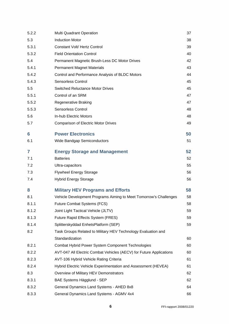
The motivation for implementing HEV technology in the civilian market is to improve fuel economy and reduce emissions, while at the same time having similar or even better performance than a conventional purely ICE power vehicle. This can be achieved by capturing energy during braking (regenerative braking) and operating the ICE more efficiently. An example is given in Figure 1.1, showing the operating principle of Toyota’s Hybrid Synergy Drive®, which is basically a parallel HEV.
Figure 1.1 Operating principle of Toyota’s Hybrid Synergy Drive® [1]
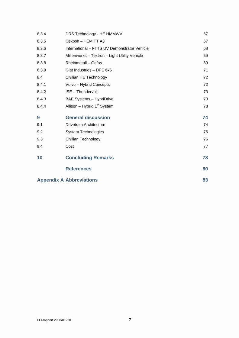
HEV is not a new concept; it was sold as early as 1900. However, due to the low price of gasoline they more or less disappeared until the oil embargo in 1970, which prompted a renewed interest in EVs and HEVs. The first modern HEV, the Toyota Prius (see Figure 1.2), was sold in Japan in 1997, and since then over a million have been sold worldwide. Currently more then 20 different HEVs are marketed by different car manufactures. The popularity of HEVs is predicted to continue to increase with the maturing of the technology, higher gasoline prices, and people’s increased environmental awareness.
The introduction of the plug-in HEV (PHEV) is a much anticipated technology. This will allow the average commuter to charge the PHEV from the electric power grid and operate in electric-only mode for 30-60 km as a pure EV. When the energy stored in the batteries is expended, the PHEV will operate as an ordinary HEV.
FFI-rapport 2008/01220 9
Figure 1.2 The third generation Toyota Prius (left) and the Lexus RX 400h (right) HEVs
There is also a great interest in HEV technology for military vehicles. The potential advantages and technical challenges are however somewhat different from the civilian market. According to [2;3], the main motivation for military HEVs is the possibility to generate the large amount of electric power required for current and future vehicle integrated systems e.g. air condition and electro-thermal chemical (ETC) cannon. Another advantage often mentioned is the improved fuel economy, potentially increased range and reduced logistics.
The HEV technology also has the possibility to introduce new functionality to the military vehicle. Electric-only propulsion will have a reduced acoustic and thermal signature and is often referred to as silent mobility. A series HEV also offers the possibility of avoiding the bulky mechanical driveline (transmission, driveshafts1, differentials etc.) altogether, potentially increasing the available volume inside the vehicle, enabling vehicle modularity, reducing the (mechanical) complexity of the vehicle driveline, reducing the logistical footprint etc.
There are several technical challenges that need to be met before we will see the fielding of military HEVs. First of all the HEV technology must surpass the conventional ICE power vehicle technology, which is a reliable and well known technology. In order to achieve this, the current state-of-the-art electric motors must be further developed with regard to certain key parameters. A new technology that will strongly improve the power electronics (high voltage and current) used to control the electric motors, is also assumed to be available within a few years.
Battery technologies and other electric energy storage technologies are other areas that must be improved to meet the requirements of e.g. capacity, electric power, cycle and calendar life.
1.1 Objective and Structure of the Report
The HEV technology is a fairly new and multidisciplinary field with numerous stakeholders and market participants. As a result, the available information varies in both quality and technical level of detail. For the specific subsystems there are a large number of objective technical papers and journal articles. However, the available information on the different military HEV demonstrators is naturally less detailed.
1 In this report the term driveshaft refers to both transverse driveshafts and longitudinal propshafts.
10 FFI-rapport 2008/01220
This report aims to describe the advantages and technical challenges of the different key technologies and discuss how this impacts the overall vehicle design. In doing so, the different key technologies will be described in some detail.
In chapter 2 an overview is given of the potential advantages and technical challenges of the technology. Chapter 3 presents some vehicle fundamentals and the basic architecture of wheeled and tracked military vehicles. The different HEV drivetrains2 are explained and discussed in chapter 4. Chapters 5, 6 and 7 presents respectively the key technologies: electric motors, power electronics and energy storage.
Chapter 8 presents different military programs and efforts related to HEV. This chapter also includes a presentation and discussion on relevant HEV demonstrators. Based on the preceding chapters, the HEV technology for military vehicles is discussed in Chapter 9. This is followed by concluding remarks in Chapter 10 .
2 The drivetrain refers to the group of components that generate power and deliver it to the wheels or tracks.
For a conventional vehicle the drivetrain consists of the engine, transmission, differentials, driveshafts etc.
FFI-rapport 2008/01220 11
2 Motivation and Technical challenges The motivation for implementing HEV technology in military vehicles is somewhat different than for the civilian market. This chapter describes the potential advantages that can be achieved for military vehicles by implementing HEV technology. The main technical challenges related to the technology are also described. It should here be pointed out that the resulting improvements in vehicle performance and also the severity of the technical challenges will depend on vehicle weight, size, configuration, role etc.
2.1 Potential Advantages
2.1.1 Increased Available Onboard Electric Power
Figure 2.1 shows the estimated power requirement for some systems that can potentially be integrated in a military vehicle. Some of these systems are in their infancy (e.g. electro-magnetic (EM) gun), but sensors and situation awareness (SA) systems, battlefield management systems (BMS), remote weapon stations (RWS), active protection systems (APS) are examples of readily available technology that require continuous and/ or peak power. A HEV must be designed to meet these electric power demands [4].
The availability of onboard power may also in some situations reduce the logistical burden by avoiding the need of a towed generator [5].
2.1.2 Improved Fuel Economy
A direct comparison of the fuel economy of an ICE powered military vehicle and a military HEV is generally difficult as the design and properties of the vehicles have to date not been directly comparable. In addition there is currently no standardized driving cycles defining load, speed, time etc as there is for civilian vehicles (see Figure 2.2).
However, evaluation tests have been performed with stock and different generations of the hybrid electric (HE) HMMWV3 at different test tracks in the US. The results of these tests indicate an average improved fuel economy of 10-20 % depending on test track [5-7].
The improved fuel economy is mainly contributed to operating the ICE at optimal speed and load and capturing energy during braking (also motor braking). The reduced fuel consumption can have several implications, such as increased range, reduced fuel tank volume and a reduced logistical burden etc. With regard to the logistical burden, in the current war in Afghanistan the logistics of transporting fuel with a sufficient quality to the soldier in the field has proven to be very costly [8].
3 The High Mobility Multipurpose Wheeled Vehicle (HMMWV), also known as humvee or hummer, is a
4x4 military vehicle used by the U.S. armed forces and exists in a number of configurations.
12 FFI-rapport 2008/01220
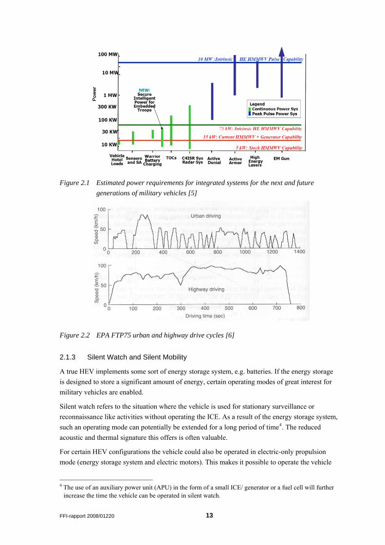
Figure 2.1 Estimated power requirements for integrated systems for the next and future generations of military vehicles [5]
Figure 2.2 EPA FTP75 urban and highway drive cycles [6]
2.1.3 Silent Watch and Silent Mobility
A true HEV implements some sort of energy storage system, e.g. batteries. If the energy storage is designed to store a significant amount of energy, certain operating modes of great interest for military vehicles are enabled.
Silent watch refers to the situation where the vehicle is used for stationary surveillance or reconnaissance like activities without operating the ICE. As a result of the energy storage system, such an operating mode can potentially be extended for a long period of time4. The reduced acoustic and thermal signature this offers is often valuable.
For certain HEV configurations the vehicle could also be operated in electric-only propulsion mode (energy storage system and electric motors). This makes it possible to operate the vehicle
4 The use of an auxiliary power unit (APU) in the form of a small ICE/ generator or a fuel cell will further
increase the time the vehicle can be operated in silent watch.
FFI-rapport 2008/01220 13
with reduced thermal and acoustic signature and is typically referred to as silent mobility. The range of such an operating mode is, however, limited due to the practical sizing of the energy storage system.
2.1.4 Vehicle Design and Architecture
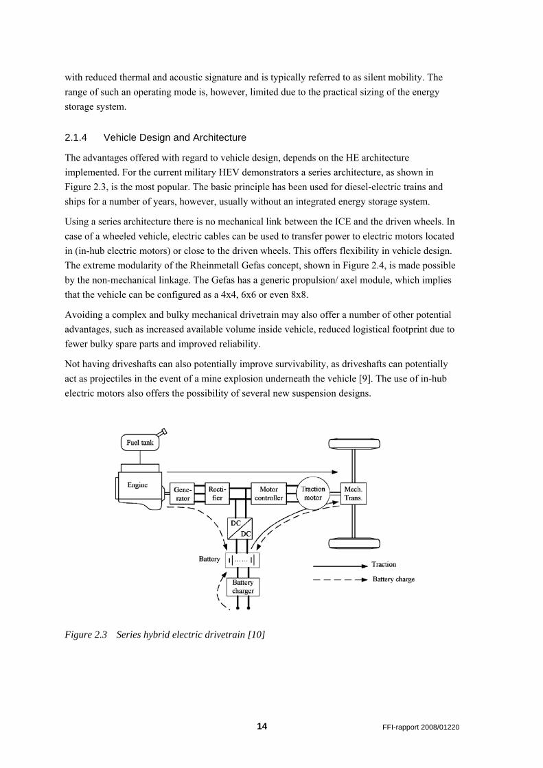
The advantages offered with regard to vehicle design, depends on the HE architecture implemented. For the current military HEV demonstrators a series architecture, as shown in Figure 2.3, is the most popular. The basic principle has been used for diesel-electric trains and ships for a number of years, however, usually without an integrated energy storage system.
Using a series architecture there is no mechanical link between the ICE and the driven wheels. In case of a wheeled vehicle, electric cables can be used to transfer power to electric motors located in (in-hub electric motors) or close to the driven wheels. This offers flexibility in vehicle design. The extreme modularity of the Rheinmetall Gefas concept, shown in Figure 2.4, is made possible by the non-mechanical linkage. The Gefas has a generic propulsion/ axel module, which implies that the vehicle can be configured as a 4x4, 6x6 or even 8x8.
Avoiding a complex and bulky mechanical drivetrain may also offer a number of other potential advantages, such as increased available volume inside vehicle, reduced logistical footprint due to fewer bulky spare parts and improved reliability.
Not having driveshafts can also potentially improve survivability, as driveshafts can potentially act as projectiles in the event of a mine explosion underneath the vehicle [9]. The use of in-hub electric motors also offers the possibility of several new suspension designs.
Figure 2.3 Series hybrid electric drivetrain [10]
14 FFI-rapport 2008/01220
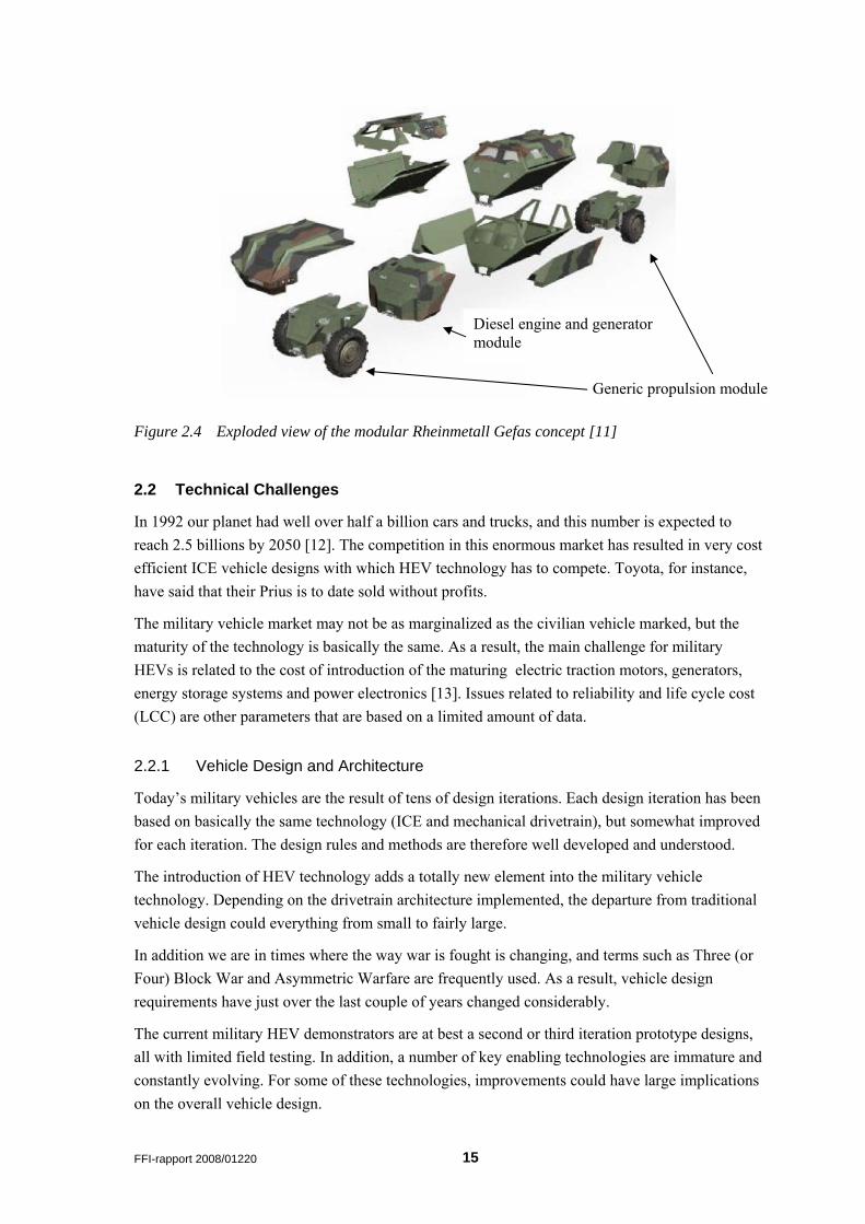
Diesel engine and generator module
Generic propulsion module
Figure 2.4 Exploded view of the modular Rheinmetall Gefas concept [11]
2.2 Technical Challenges
In 1992 our planet had well over half a billion cars and trucks, and this number is expected to reach 2.5 billions by 2050 [12]. The competition in this enormous market has resulted in very cost efficient ICE vehicle designs with which HEV technology has to compete. Toyota, for instance, have said that their Prius is to date sold without profits.
The military vehicle market may not be as marginalized as the civilian vehicle marked, but the maturity of the technology is basically the same. As a result, the main challenge for military HEVs is related to the cost of introduction of the maturing electric traction motors, generators, energy storage systems and power electronics [13]. Issues related to reliability and life cycle cost (LCC) are other parameters that are based on a limited amount of data.
2.2.1 Vehicle Design and Architecture
Today’s military vehicles are the result of tens of design iterations. Each design iteration has been based on basically the same technology (ICE and mechanical drivetrain), but somewhat improved for each iteration. The design rules and methods are therefore well developed and understood.
The introduction of HEV technology adds a totally new element into the military vehicle technology. Depending on the drivetrain architecture implemented, the departure from traditional vehicle design could everything from small to fairly large.
In addition we are in times where the way war is fought is changing, and terms such as Three (or Four) Block War and Asymmetric Warfare are frequently used. As a result, vehicle design requirements have just over the last couple of years changed considerably.
The current military HEV demonstrators are at best a second or third iteration prototype designs, all with limited field testing. In addition, a number of key enabling technologies are immature and constantly evolving. For some of these technologies, improvements could have large implications on the overall vehicle design.
FFI-rapport 2008/01220 15
2.2.2 Electric Motors
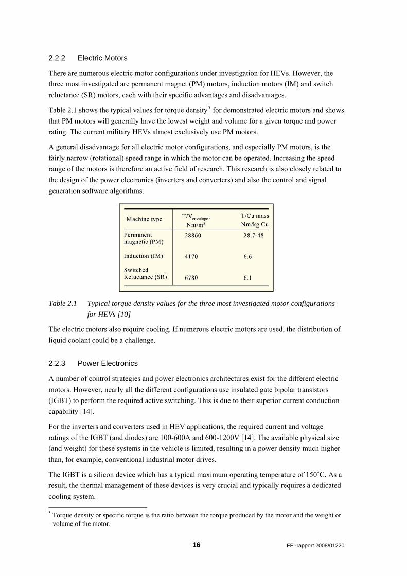
There are numerous electric motor configurations under investigation for HEVs. However, the three most investigated are permanent magnet (PM) motors, induction motors (IM) and switch reluctance (SR) motors, each with their specific advantages and disadvantages.
Table 2.1 shows the typical values for torque density5 for demonstrated electric motors and shows that PM motors will generally have the lowest weight and volume for a given torque and power rating. The current military HEVs almost exclusively use PM motors.
A general disadvantage for all electric motor configurations, and especially PM motors, is the fairly narrow (rotational) speed range in which the motor can be operated. Increasing the speed range of the motors is therefore an active field of research. This research is also closely related to the design of the power electronics (inverters and converters) and also the control and signal generation software algorithms.
Table 2.1 Typical torque density values for the three most investigated motor configurations for HEVs [10]
The electric motors also require cooling. If numerous electric motors are used, the distribution of liquid coolant could be a challenge.
2.2.3 Power Electronics
A number of control strategies and power electronics architectures exist for the different electric motors. However, nearly all the different configurations use insulated gate bipolar transistors (IGBT) to perform the required active switching. This is due to their superior current conduction capability [14].
For the inverters and converters used in HEV applications, the required current and voltage ratings of the IGBT (and diodes) are 100-600A and 600-1200V [14]. The available physical size (and weight) for these systems in the vehicle is limited, resulting in a power density much higher than, for example, conventional industrial motor drives.
The IGBT is a silicon device which has a typical maximum operating temperature of 150˚C. As a result, the thermal management of these devices is very crucial and typically requires a dedicated cooling system. 5 Torque density or specific torque is the ratio between the torque produced by the motor and the weight or
volume of the motor.
16 FFI-rapport 2008/01220
Wide bandgap (WBG) semiconductors such as Silicon Carbide (SiC) with a maximum operating temperature of ~500˚C show great promise for power electronics, but the technology is immature.
2.2.4 Energy Storage
The energy storage technologies being utilized for HEVs are rechargeable batteries, ultra-capacitors and flywheels. A flywheel stores mechanical kinetic energy that can be converted to electric energy using an electric generator.
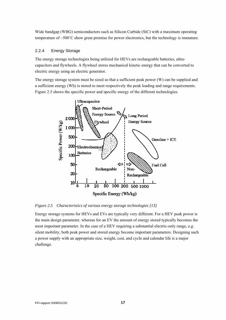
The energy storage system must be sized so that a sufficient peak power (W) can be supplied and a sufficient energy (Wh) is stored to meet respectively the peak loading and range requirements. Figure 2.5 shows the specific power and specific energy of the different technologies.
Figure 2.5 Characteristics of various energy storage technologies [13]
Energy storage systems for HEVs and EVs are typically very different. For a HEV peak power is the main design parameter, whereas for an EV the amount of energy stored typically becomes the most important parameter. In the case of a HEV requiring a substantial electric-only range, e.g. silent mobility, both peak power and stored energy become important parameters. Designing such a power supply with an appropriate size, weight, cost, and cycle and calendar life is a major challenge.
FFI-rapport 2008/01220 17
3 Vehicle Fundamentals There exists a large amount of literature on this topic. This chapter aims to present some important terms used in the following chapters.
3.1 General Description of Forces Acting on a Vehicle
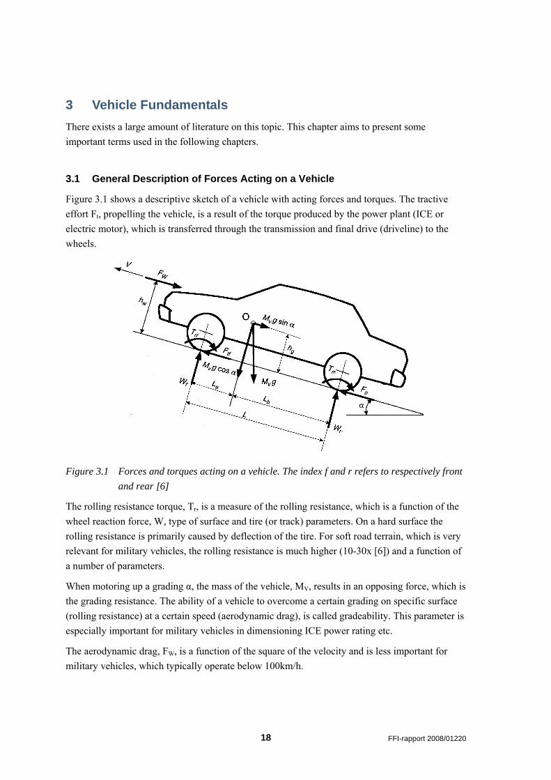
Figure 3.1 shows a descriptive sketch of a vehicle with acting forces and torques. The tractive effort Ft, propelling the vehicle, is a result of the torque produced by the power plant (ICE or electric motor), which is transferred through the transmission and final drive (driveline) to the wheels.
Figure 3.1 Forces and torques acting on a vehicle. The index f and r refers to respectively front and rear [6]
The rolling resistance torque, Tr, is a measure of the rolling resistance, which is a function of the wheel reaction force, W, type of surface and tire (or track) parameters. On a hard surface the rolling resistance is primarily caused by deflection of the tire. For soft road terrain, which is very relevant for military vehicles, the rolling resistance is much higher (10-30x [6]) and a function of a number of parameters.
When motoring up a grading α, the mass of the vehicle, MV, results in an opposing force, which is the grading resistance. The ability of a vehicle to overcome a certain grading on specific surface (rolling resistance) at a certain speed (aerodynamic drag), is called gradeability. This parameter is especially important for military vehicles in dimensioning ICE power rating etc.
The aerodynamic drag, FW, is a function of the square of the velocity and is less important for military vehicles, which typically operate below 100km/h.
18 FFI-rapport 2008/01220
3.2 Vehicle Characteristics
3.2.1 Power Plant Characteristics
The torque of a power plant is given as
PP N
P30PTπ
=ω
= (3.1)
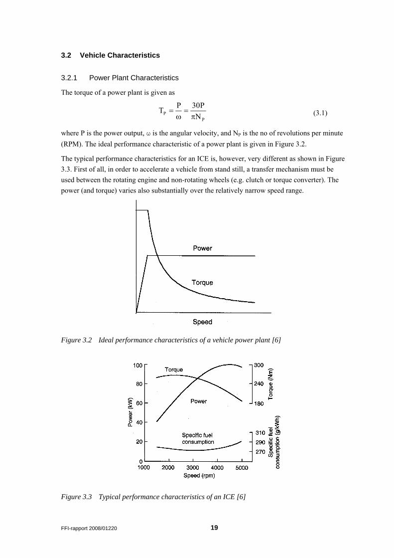
where P is the power output, ω is the angular velocity, and NP is the no of revolutions per minute (RPM). The ideal performance characteristic of a power plant is given in Figure 3.2.
The typical performance characteristics for an ICE is, however, very different as shown in Figure 3.3. First of all, in order to accelerate a vehicle from stand still, a transfer mechanism must be used between the rotating engine and non-rotating wheels (e.g. clutch or torque converter). The power (and torque) varies also substantially over the relatively narrow speed range.
Figure 3.2 Ideal performance characteristics of a vehicle power plant [6]
Figure 3.3 Typical performance characteristics of an ICE [6]
FFI-rapport 2008/01220 19
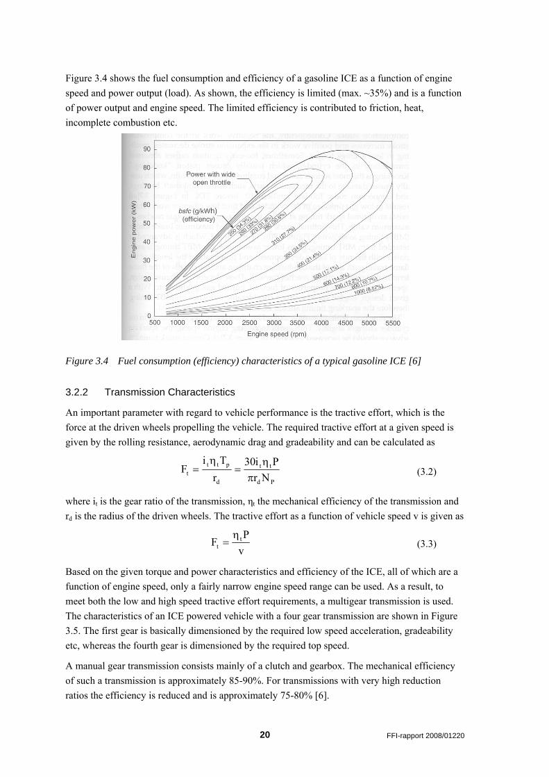
Figure 3.4 shows the fuel consumption and efficiency of a gasoline ICE as a function of engine speed and power output (load). As shown, the efficiency is limited (max. ~35%) and is a function of power output and engine speed. The limited efficiency is contributed to friction, heat, incomplete combustion etc.
Figure 3.4 Fuel consumption (efficiency) characteristics of a typical gasoline ICE [6]
3.2.2 Transmission Characteristics
An important parameter with regard to vehicle performance is the tractive effort, which is the force at the driven wheels propelling the vehicle. The required tractive effort at a given speed is given by the rolling resistance, aerodynamic drag and gradeability and can be calculated as
Pd
tt
d
pttt Nr
Pi30r
TiF
πη
=η
= (3.2)
where it is the gear ratio of the transmission, ηt the mechanical efficiency of the transmission and rd is the radius of the driven wheels. The tractive effort as a function of vehicle speed v is given as
vP
F tt
η= (3.3)
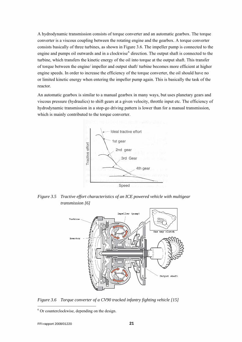
Based on the given torque and power characteristics and efficiency of the ICE, all of which are a function of engine speed, only a fairly narrow engine speed range can be used. As a result, to meet both the low and high speed tractive effort requirements, a multigear transmission is used. The characteristics of an ICE powered vehicle with a four gear transmission are shown in Figure 3.5. The first gear is basically dimensioned by the required low speed acceleration, gradeability etc, whereas the fourth gear is dimensioned by the required top speed.
A manual gear transmission consists mainly of a clutch and gearbox. The mechanical efficiency of such a transmission is approximately 85-90%. For transmissions with very high reduction ratios the efficiency is reduced and is approximately 75-80% [6].
20 FFI-rapport 2008/01220
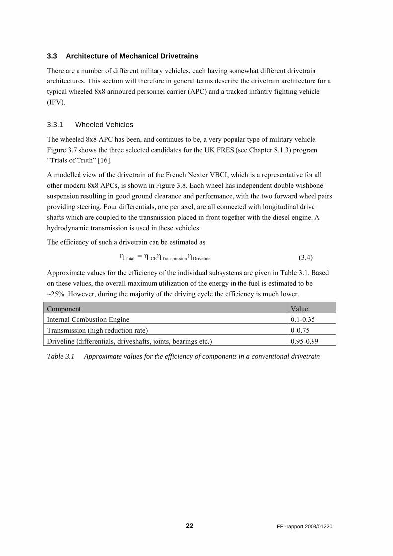
A hydrodynamic transmission consists of torque converter and an automatic gearbox. The torque converter is a viscous coupling between the rotating engine and the gearbox. A torque converter consists basically of three turbines, as shown in Figure 3.6. The impeller pump is connected to the engine and pumps oil outwards and in a clockwise6 direction. The output shaft is connected to the turbine, which transfers the kinetic energy of the oil into torque at the output shaft. This transfer of torque between the engine/ impeller and output shaft/ turbine becomes more efficient at higher engine speeds. In order to increase the efficiency of the torque converter, the oil should have no or limited kinetic energy when entering the impeller pump again. This is basically the task of the reactor.
An automatic gearbox is similar to a manual gearbox in many ways, but uses planetary gears and viscous pressure (hydraulics) to shift gears at a given velocity, throttle input etc. The efficiency of hydrodynamic transmission in a stop-go driving pattern is lower than for a manual transmission, which is mainly contributed to the torque converter.
Figure 3.5 Tractive effort characteristics of an ICE powered vehicle with multigear transmission [6]
Figure 3.6 Torque converter of a CV90 tracked infantry fighting vehicle [15] 6 Or counterclockwise, depending on the design.
FFI-rapport 2008/01220 21
3.3 Architecture of Mechanical Drivetrains
There are a number of different military vehicles, each having somewhat different drivetrain architectures. This section will therefore in general terms describe the drivetrain architecture for a typical wheeled 8x8 armoured personnel carrier (APC) and a tracked infantry fighting vehicle (IFV).
3.3.1 Wheeled Vehicles
The wheeled 8x8 APC has been, and continues to be, a very popular type of military vehicle. Figure 3.7 shows the three selected candidates for the UK FRES (see Chapter 8.1.3) program “Trials of Truth” [16].
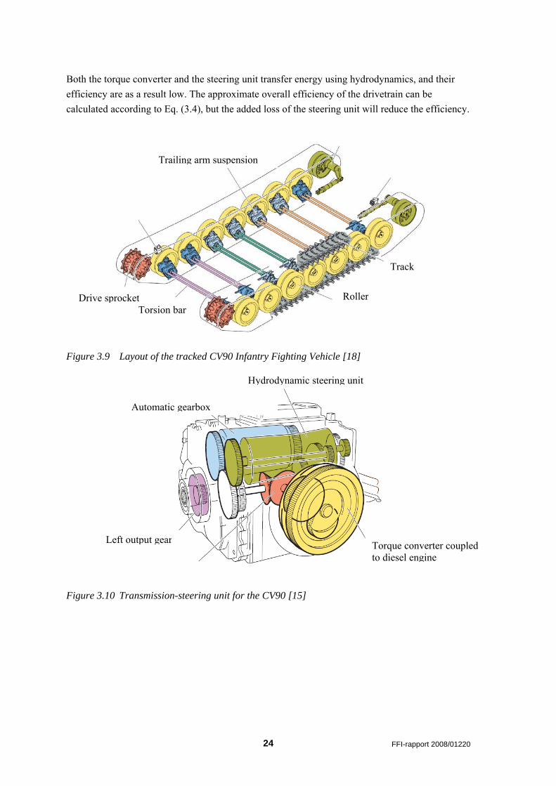
A modelled view of the drivetrain of the French Nexter VBCI, which is a representative for all other modern 8x8 APCs, is shown in Figure 3.8. Each wheel has independent double wishbone suspension resulting in good ground clearance and performance, with the two forward wheel pairs providing steering. Four differentials, one per axel, are all connected with longitudinal drive shafts which are coupled to the transmission placed in front together with the diesel engine. A hydrodynamic transmission is used in these vehicles.
The efficiency of such a drivetrain can be estimated as
DrivelineonTransmissiICETotal ηηη=η (3.4)
Approximate values for the efficiency of the individual subsystems are given in Table 3.1. Based on these values, the overall maximum utilization of the energy in the fuel is estimated to be ~25%. However, during the majority of the driving cycle the efficiency is much lower.
Component Value Internal Combustion Engine 0.1-0.35 Transmission (high reduction rate) 0-0.75 Driveline (differentials, driveshafts, joints, bearings etc.) 0.95-0.99
Table 3.1 Approximate values for the efficiency of components in a conventional drivetrain
22 FFI-rapport 2008/01220
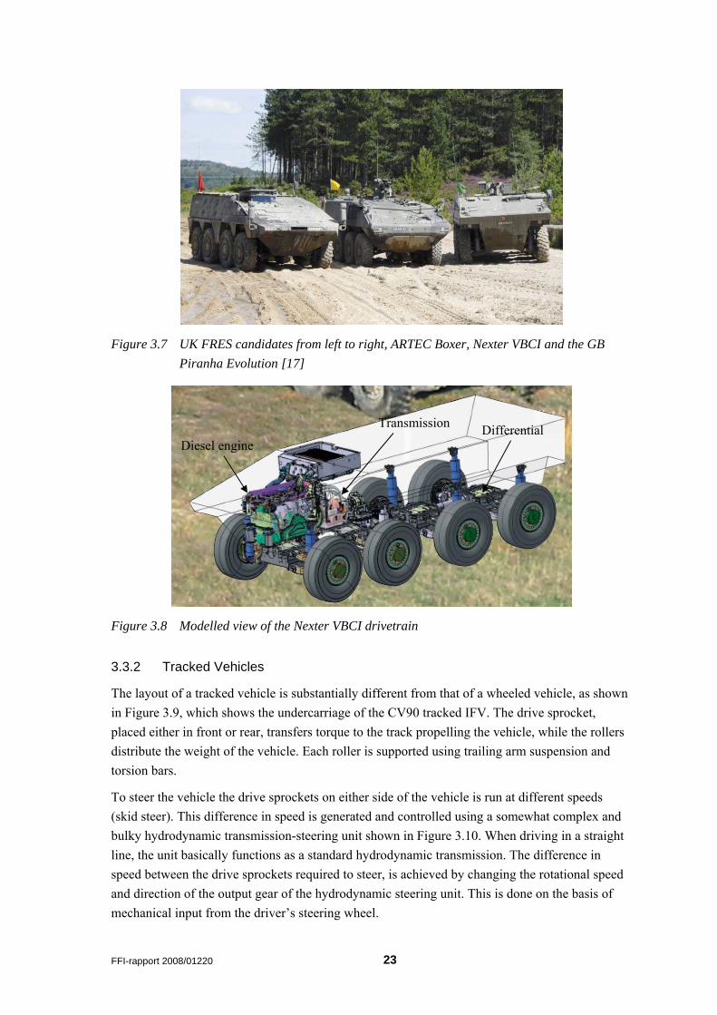
Figure 3.7 UK FRES candidates from left to right, ARTEC Boxer, Nexter VBCI and the GB Piranha Evolution [17]
Transmission Differential Diesel engine
Figure 3.8 Modelled view of the Nexter VBCI drivetrain
3.3.2 Tracked Vehicles
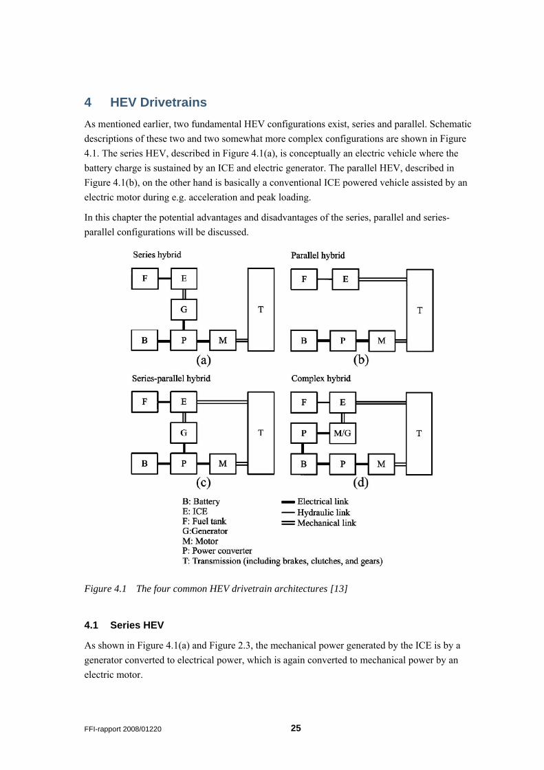
The layout of a tracked vehicle is substantially different from that of a wheeled vehicle, as shown in Figure 3.9, which shows the undercarriage of the CV90 tracked IFV. The drive sprocket, placed either in front or rear, transfers torque to the track propelling the vehicle, while the rollers distribute the weight of the vehicle. Each roller is supported using trailing arm suspension and torsion bars.
To steer the vehicle the drive sprockets on either side of the vehicle is run at different speeds (skid steer). This difference in speed is generated and controlled using a somewhat complex and bulky hydrodynamic transmission-steering unit shown in Figure 3.10. When driving in a straight line, the unit basically functions as a standard hydrodynamic transmission. The difference in speed between the drive sprockets required to steer, is achieved by changing the rotational speed and direction of the output gear of the hydrodynamic steering unit. This is done on the basis of mechanical input from the driver’s steering wheel.
FFI-rapport 2008/01220 23
Both the torque converter and the steering unit transfer energy using hydrodynamics, and their efficiency are as a result low. The approximate overall efficiency of the drivetrain can be calculated according to Eq. (3.4), but the added loss of the steering unit will reduce the efficiency.
Trailing arm suspension
Track
RollerDrive sprocket Torsion bar
Figure 3.9 Layout of the tracked CV90 Infantry Fighting Vehicle [18]
Hydrodynamic steering unit
Automatic gearbox
Left output gear Torque converter coupled to diesel engine
Figure 3.10 Transmission-steering unit for the CV90 [15]
24 FFI-rapport 2008/01220
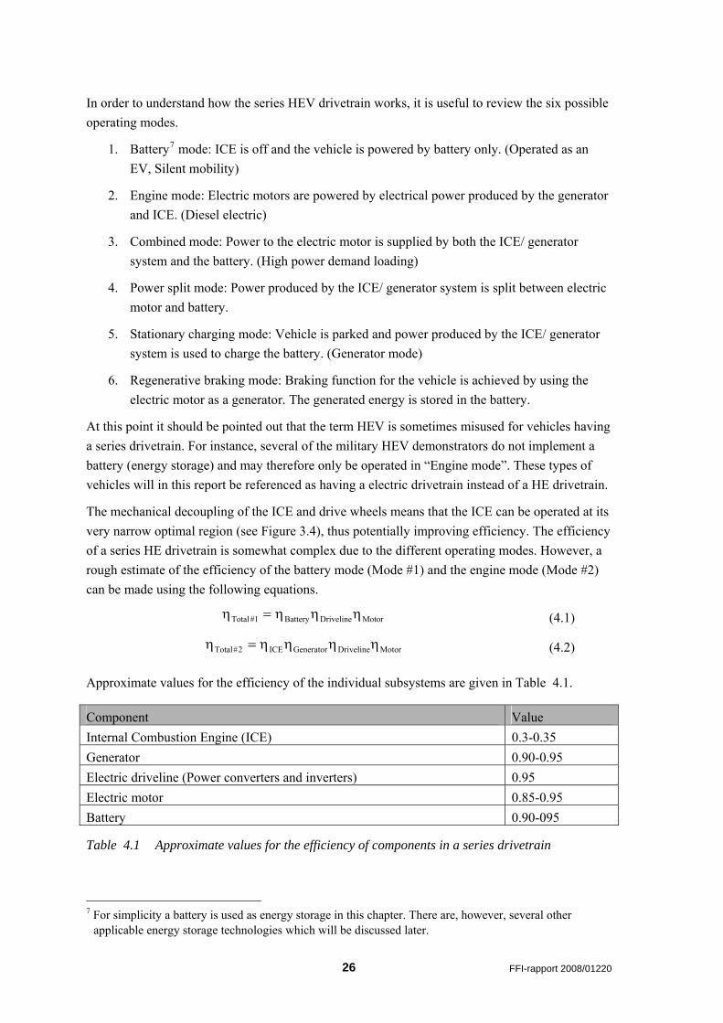
4 HEV Drivetrains As mentioned earlier, two fundamental HEV configurations exist, series and parallel. Schematic descriptions of these two and two somewhat more complex configurations are shown in Figure 4.1. The series HEV, described in Figure 4.1(a), is conceptually an electric vehicle where the battery charge is sustained by an ICE and electric generator. The parallel HEV, described in Figure 4.1(b), on the other hand is basically a conventional ICE powered vehicle assisted by an electric motor during e.g. acceleration and peak loading.
In this chapter the potential advantages and disadvantages of the series, parallel and series-parallel configurations will be discussed.
Figure 4.1 The four common HEV drivetrain architectures [13]
4.1 Series HEV
As shown in Figure 4.1(a) and Figure 2.3, the mechanical power generated by the ICE is by a generator converted to electrical power, which is again converted to mechanical power by an electric motor.
FFI-rapport 2008/01220 25
In order to understand how the series HEV drivetrain works, it is useful to review the six possible operating modes.
1. Battery7 mode: ICE is off and the vehicle is powered by battery only. (Operated as an EV, Silent mobility)
2. Engine mode: Electric motors are powered by electrical power produced by the generator and ICE. (Diesel electric)
3. Combined mode: Power to the electric motor is supplied by both the ICE/ generator system and the battery. (High power demand loading)
4. Power split mode: Power produced by the ICE/ generator system is split between electric motor and battery.
5. Stationary charging mode: Vehicle is parked and power produced by the ICE/ generator system is used to charge the battery. (Generator mode)
6. Regenerative braking mode: Braking function for the vehicle is achieved by using the electric motor as a generator. The generated energy is stored in the battery.
At this point it should be pointed out that the term HEV is sometimes misused for vehicles having a series drivetrain. For instance, several of the military HEV demonstrators do not implement a battery (energy storage) and may therefore only be operated in “Engine mode”. These types of vehicles will in this report be referenced as having a electric drivetrain instead of a HE drivetrain.
The mechanical decoupling of the ICE and drive wheels means that the ICE can be operated at its very narrow optimal region (see Figure 3.4), thus potentially improving efficiency. The efficiency of a series HE drivetrain is somewhat complex due to the different operating modes. However, a rough estimate of the efficiency of the battery mode (Mode #1) and the engine mode (Mode #2) can be made using the following equations.
MotorDrivelineBattery1#Total ηηη=η (4.1)
MotorDrivelineGeneratorICE2#Total ηηηη=η (4.2)
Approximate values for the efficiency of the individual subsystems are given in Table 4.1.
Component Value Internal Combustion Engine (ICE) 0.3-0.35 Generator 0.90-0.95 Electric driveline (Power converters and inverters) 0.95 Electric motor 0.85-0.95 Battery 0.90-095
Table 4.1 Approximate values for the efficiency of components in a series drivetrain
7 For simplicity a battery is used as energy storage in this chapter. There are, however, several other
applicable energy storage technologies which will be discussed later.
26 FFI-rapport 2008/01220
When comparing the maximum efficiency of the engine mode with the maximum efficiency of a conventional mechanical drivetrain (Eq. (3.4) ) the benefits are marginal. However, a conventional mechanical drivetrain is operated at a sub-optimal efficiency a high percentage of the time, resulting in a larger difference between the two technologies. The use of a battery as energy buffer, charged from regenerative braking and/ or generator, can further improve the efficiency.
4.1.1 Advantages
The mechanical decoupling of the engine from the driving wheels offers flexibility in vehicle design, as electrical wires can be used to transfer the power for propulsion around the vehicle instead of numerous rigid mechanical driveshafts and bulky differentials. An example of vehicle modularity that can be achieved is demonstrated in Figure 2.4.
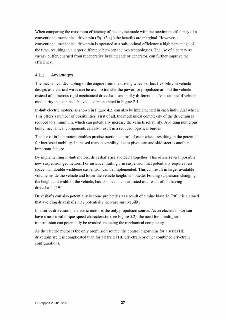
In-hub electric motors, as shown in Figure 4.2, can also be implemented in each individual wheel. This offers a number of possibilities. First of all, the mechanical complexity of the drivetrain is reduced to a minimum, which can potentially increase the vehicle reliability. Avoiding numerous bulky mechanical components can also result in a reduced logistical burden.
The use of in-hub motors enables precise traction control of each wheel, resulting in the potential for increased mobility. Increased manoeuvrability due to pivot turn and skid steer is another important feature.
By implementing in-hub motors, driveshafts are avoided altogether. This offers several possible new suspension geometries. For instance, trailing arm suspension that potentially requires less space than double wishbone suspension can be implemented. This can result in larger available volume inside the vehicle and lower the vehicle height/ silhouette. Folding suspension changing the height and width of the vehicle, has also been demonstrated as a result of not having driveshafts [19].
Driveshafts can also potentially become projectiles as a result of a mine blast. In [20] it is claimed that avoiding driveshafts may potentially increase survivability.
In a series drivetrain the electric motor is the only propulsion source. As an electric motor can have a near ideal torque-speed characteristic (see Figure 5.2), the need for a multigear transmission can potentially be avoided, reducing the mechanical complexity.
As the electric motor is the only propulsion source, the control algorithms for a series HE drivetrain are less complicated than for a parallel HE drivetrain or other combined drivetrain configurations.
FFI-rapport 2008/01220 27
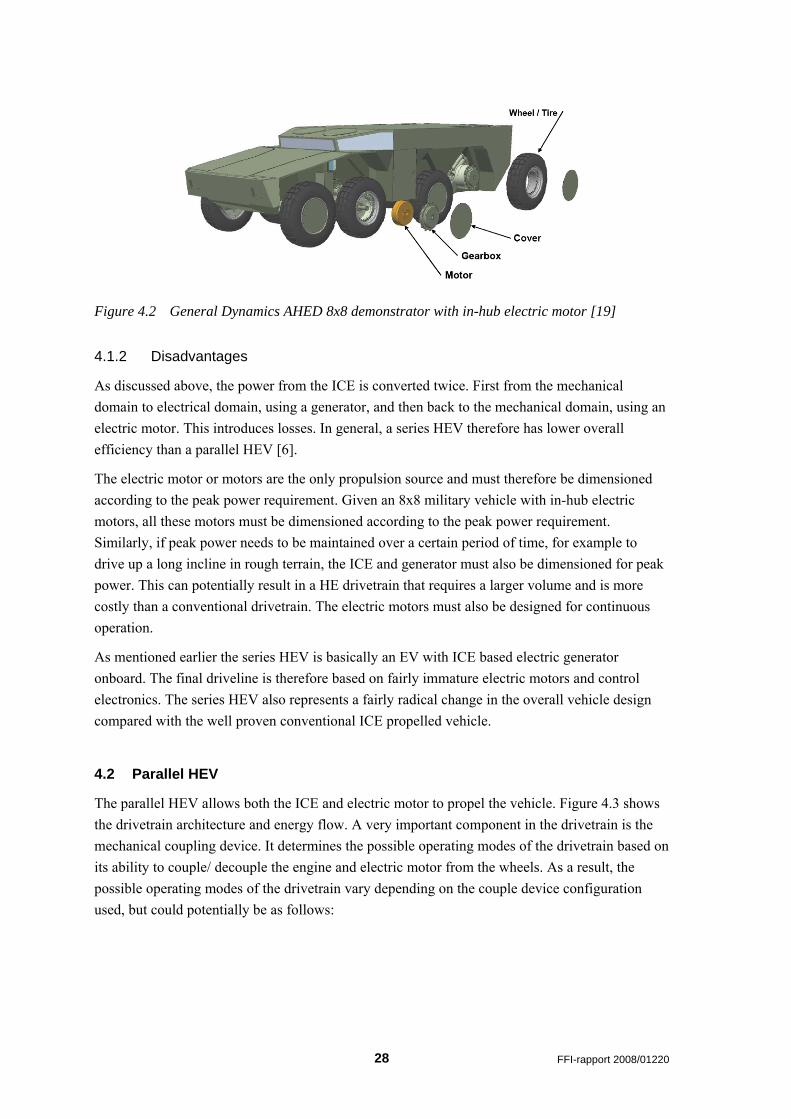
Figure 4.2 General Dynamics AHED 8x8 demonstrator with in-hub electric motor [19]
4.1.2 Disadvantages
As discussed above, the power from the ICE is converted twice. First from the mechanical domain to electrical domain, using a generator, and then back to the mechanical domain, using an electric motor. This introduces losses. In general, a series HEV therefore has lower overall efficiency than a parallel HEV [6].
The electric motor or motors are the only propulsion source and must therefore be dimensioned according to the peak power requirement. Given an 8x8 military vehicle with in-hub electric motors, all these motors must be dimensioned according to the peak power requirement. Similarly, if peak power needs to be maintained over a certain period of time, for example to drive up a long incline in rough terrain, the ICE and generator must also be dimensioned for peak power. This can potentially result in a HE drivetrain that requires a larger volume and is more costly than a conventional drivetrain. The electric motors must also be designed for continuous operation.
As mentioned earlier the series HEV is basically an EV with ICE based electric generator onboard. The final driveline is therefore based on fairly immature electric motors and control electronics. The series HEV also represents a fairly radical change in the overall vehicle design compared with the well proven conventional ICE propelled vehicle.
4.2 Parallel HEV
The parallel HEV allows both the ICE and electric motor to propel the vehicle. Figure 4.3 shows the drivetrain architecture and energy flow. A very important component in the drivetrain is the mechanical coupling device. It determines the possible operating modes of the drivetrain based on its ability to couple/ decouple the engine and electric motor from the wheels. As a result, the possible operating modes of the drivetrain vary depending on the couple device configuration used, but could potentially be as follows:
28 FFI-rapport 2008/01220
1. Electric motor mode: ICE is off and the electric motor propels the vehicle using energy
from the battery (Silent mobility).
2. Engine mode: Vehicle is propelled as a traditional ICE vehicle.
3. Combined mode: Vehicle is propelled by both ICE and electric motor.
4. Power split mode: Power delivered by the ICE is used to both propel the vehicle and charge the batteries by using the electric motor as a generator.
5. Stationary charging mode: Vehicle is parked, and power produced by the ICE system is used to charge the batteries by using the electric motor as a generator (Generator mode)
6. Regenerative braking mode: Vehicle braking is achieved by using the electric motor as a generator. The generated energy is stored in a battery.
Figure 4.3 Parallel hybrid-electric drivetrain [10]
4.2.1 Mechanical Coupling
The mechanical coupling device in Figure 4.3 can either be a torque or speed coupling. As the name implies, the torque coupling configuration adds the torque of the ICE engine and electric motor. The resulting torque and rotational speed can be calculated as
2In21In1Out TkTkT += (4.3)
2
2In
1
1InOut kk
ω=
ω=ω (4.4)
where T is the torque, ω the rotational speed and k the gear ratio.
FFI-rapport 2008/01220 29
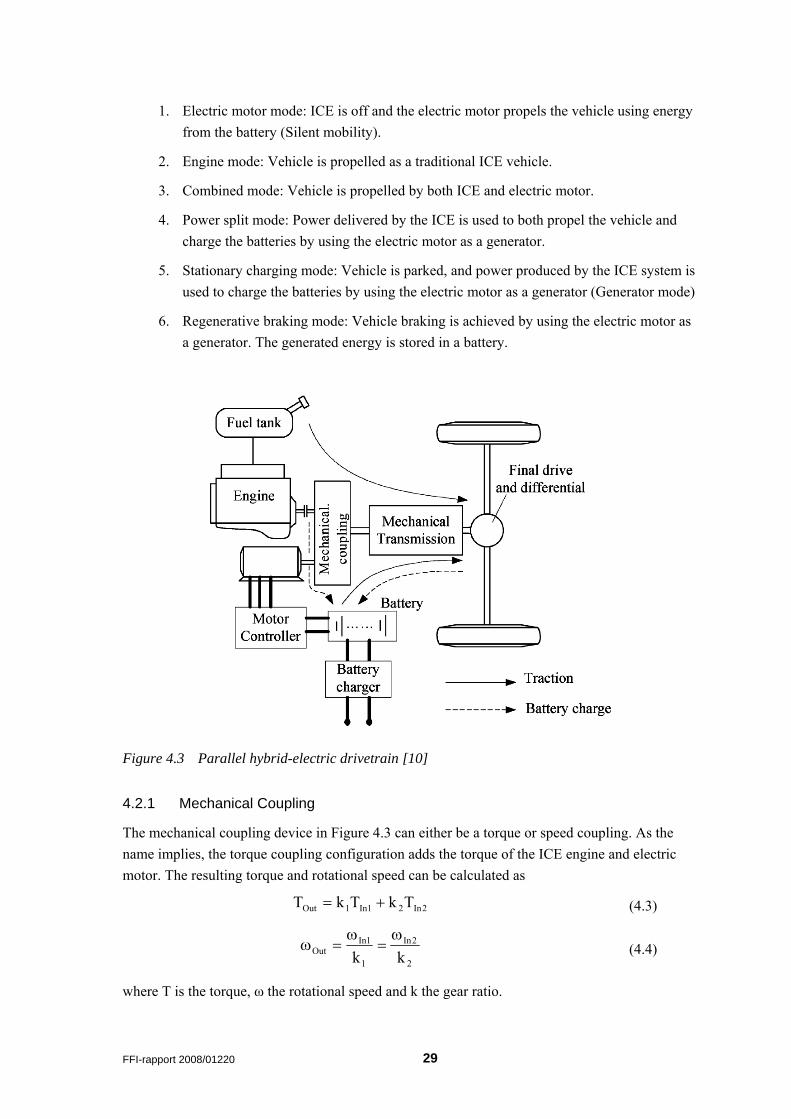
An example of a torque coupled drivetrain is shown in Figure 4.4. Here the coupling device is an electric motor where the rotor is directly coupled to the driveshaft from the engine (k1= k2=1). Using this configuration the stationary charging operating mode (Mode #5) is not possible due to the mechanical coupling of engine and transmission. However, this can be solved by adding an additional clutch.
A speed coupled drivetrain using a planetary gear unit (Figure 4.6) is given in Figure 4.5. The characteristics of such a device can be calculated according to
2In21In1Out kk ω+ω=ω (4.5)
2
2In
1
1InOut k
Tk
TT == (4.6)
An important point here is that the rotational speed and direction of the two inputs are uncoupled. This makes it for instance possible to charge batteries when stationary (Mode #5). In this case the electric motor coupled to the ring gear functions as a generator and rotates in the opposite direction of the engine input on the sun gear.
Lock 1 is engaged for electric motor only propulsion and during regenerative braking. The ring gear lock, Lock 2, is used for engine only propulsion.
Figure 4.4 A single axel torque coupled parallel drivetrain [6]
30 FFI-rapport 2008/01220
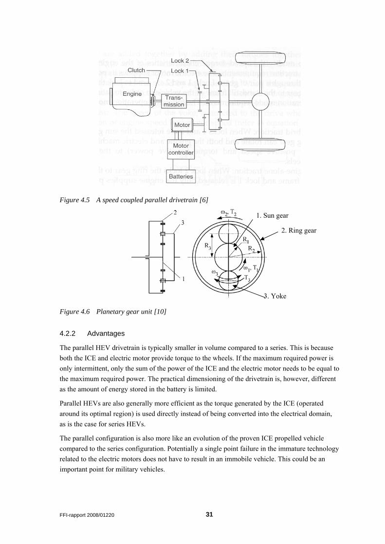
Figure 4.5 A speed coupled parallel drivetrain [6]
1. Sun gear
Figure 4.6 Planetary gear unit [10]
4.2.2 Advantages
The parallel HEV drivetrain is typically smaller in volume compared to a series. This is because both the ICE and electric motor provide torque to the wheels. If the maximum required power is only intermittent, only the sum of the power of the ICE and the electric motor needs to be equal to the maximum required power. The practical dimensioning of the drivetrain is, however, different as the amount of energy stored in the battery is limited.
Parallel HEVs are also generally more efficient as the torque generated by the ICE (operated around its optimal region) is used directly instead of being converted into the electrical domain, as is the case for series HEVs.
The parallel configuration is also more like an evolution of the proven ICE propelled vehicle compared to the series configuration. Potentially a single point failure in the immature technology related to the electric motors does not have to result in an immobile vehicle. This could be an important point for military vehicles.
2. Ring gear
3. Yoke
FFI-rapport 2008/01220 31
4.2.3 Disadvantages
The parallel HEV drivetrain is fairly complex. Due to the multiple variable parameters related to both power supplies and the wide range of operating cycles, the control algorithms become complex.
Since the ICE is not fully decoupled from the wheels, it is also difficult to operate the engine at its narrow optimal region. This affects the overall efficiency.
The vehicle design flexibility offered by the series drivetrain is not possible when implementing a parallel drivetrain. This because a traditional driveline with driveshafts, differentials etc. is required. With regard to logistics this implies that spare parts for both the traditional driveline and the HE driveline must be kept in stock.
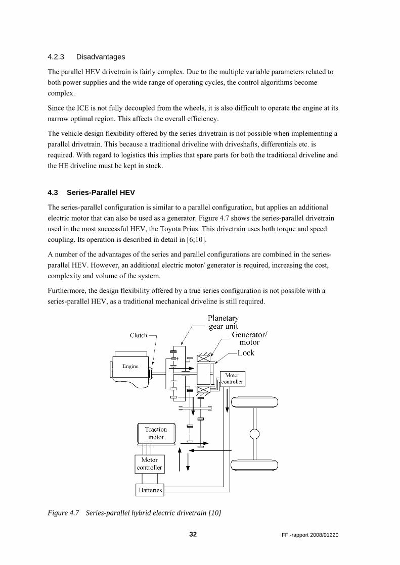
4.3 Series-Parallel HEV
The series-parallel configuration is similar to a parallel configuration, but applies an additional electric motor that can also be used as a generator. Figure 4.7 shows the series-parallel drivetrain used in the most successful HEV, the Toyota Prius. This drivetrain uses both torque and speed coupling. Its operation is described in detail in [6;10].
A number of the advantages of the series and parallel configurations are combined in the series-parallel HEV. However, an additional electric motor/ generator is required, increasing the cost, complexity and volume of the system.
Furthermore, the design flexibility offered by a true series configuration is not possible with a series-parallel HEV, as a traditional mechanical driveline is still required.
Figure 4.7 Series-parallel hybrid electric drivetrain [10]
32 FFI-rapport 2008/01220
5 Electric Motor Drives Depending on the drivetrain configuration, the electric motor has somewhat different roles. In a series configuration the electric motor is the only torque source, whereas in a parallel configuration the electric motor typically provides additional torque during high loads.
The requirements for electric motors for HEVs differ largely from the mature electric motors used in industrial applications. Important requirements are
− High torque and power density
− High torque at zero and low speeds
− High power for cruising
− Wide speed range to avoid multispeed transmission or excessive power rating
− High efficiency
− High reliability and robustness appropriate to the vehicle environment
− Acceptable cost
For traction applications induction motors (IM), switched reluctance motors (SRM) and permanent magnet motors (PM) are the most popular. These will be presented and discussed in this chapter. As an introduction to electric motors, a simple DC motor will also be presented.
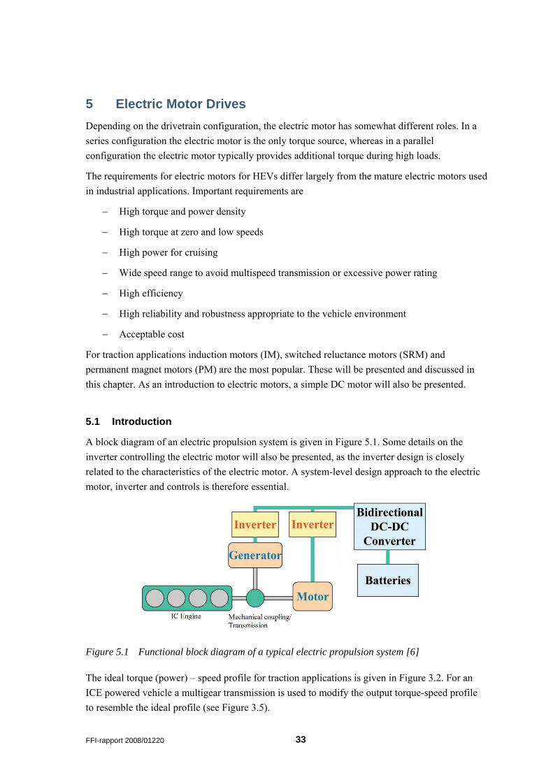
5.1 Introduction
A block diagram of an electric propulsion system is given in Figure 5.1. Some details on the inverter controlling the electric motor will also be presented, as the inverter design is closely related to the characteristics of the electric motor. A system-level design approach to the electric motor, inverter and controls is therefore essential.
Figure 5.1 Functional block diagram of a typical electric propulsion system [6]
The ideal torque (power) – speed profile for traction applications is given in Figure 3.2. For an ICE powered vehicle a multigear transmission is used to modify the output torque-speed profile to resemble the ideal profile (see Figure 3.5).
FFI-rapport 2008/01220 33
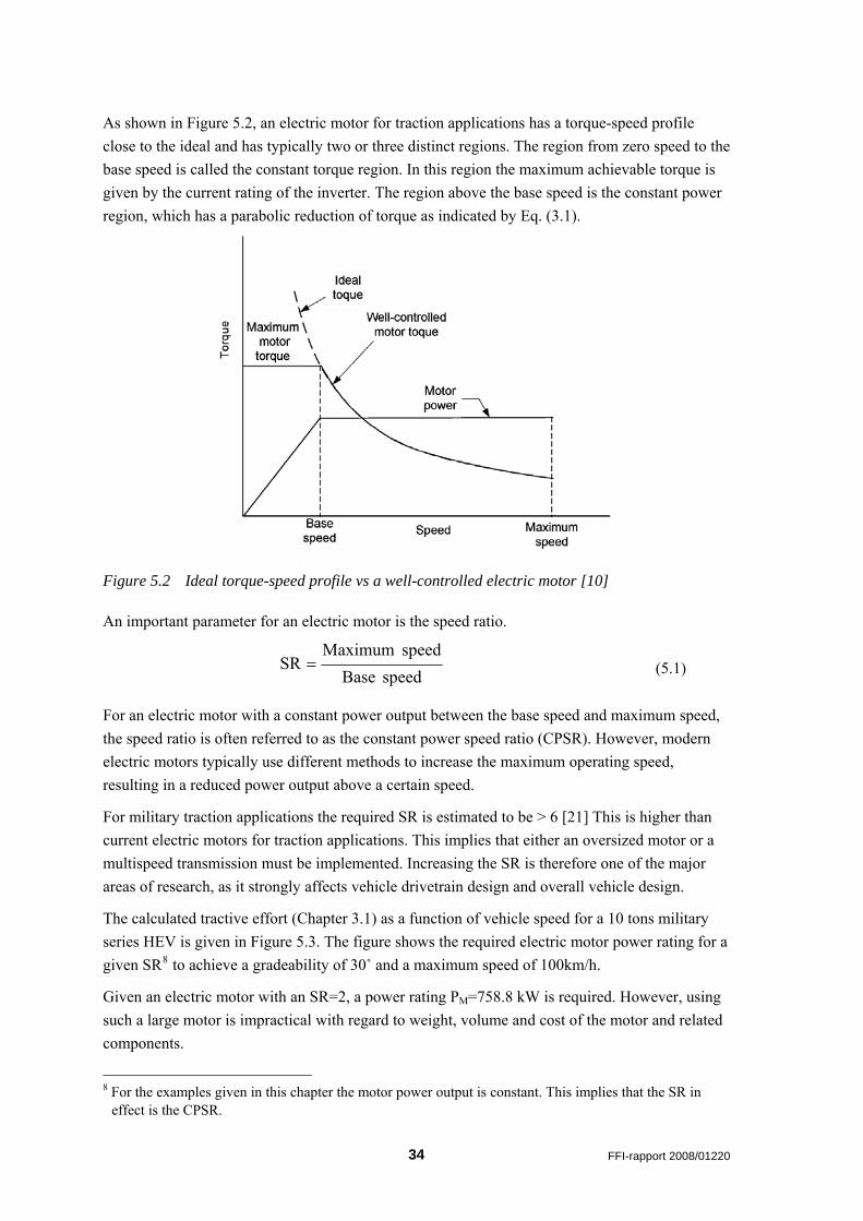
As shown in Figure 5.2, an electric motor for traction applications has a torque-speed profile close to the ideal and has typically two or three distinct regions. The region from zero speed to the base speed is called the constant torque region. In this region the maximum achievable torque is given by the current rating of the inverter. The region above the base speed is the constant power region, which has a parabolic reduction of torque as indicated by Eq. (3.1).
Figure 5.2 Ideal torque-speed profile vs a well-controlled electric motor [10]
An important parameter for an electric motor is the speed ratio.
speedBasespeedMaximum
SR = (5.1)
For an electric motor with a constant power output between the base speed and maximum speed, the speed ratio is often referred to as the constant power speed ratio (CPSR). However, modern electric motors typically use different methods to increase the maximum operating speed, resulting in a reduced power output above a certain speed.
For military traction applications the required SR is estimated to be > 6 [21] This is higher than current electric motors for traction applications. This implies that either an oversized motor or a multispeed transmission must be implemented. Increasing the SR is therefore one of the major areas of research, as it strongly affects vehicle drivetrain design and overall vehicle design.
The calculated tractive effort (Chapter 3.1) as a function of vehicle speed for a 10 tons military series HEV is given in Figure 5.3. The figure shows the required electric motor power rating for a given SR8 to achieve a gradeability of 30˚ and a maximum speed of 100km/h.
Given an electric motor with an SR=2, a power rating PM=758.8 kW is required. However, using such a large motor is impractical with regard to weight, volume and cost of the motor and related components.
8 For the examples given in this chapter the motor power output is constant. This implies that the SR in
effect is the CPSR.
34 FFI-rapport 2008/01220
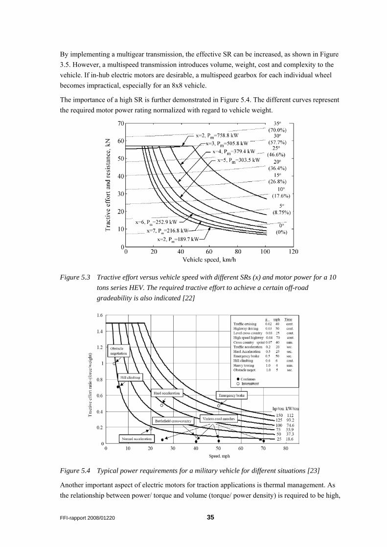
By implementing a multigear transmission, the effective SR can be increased, as shown in Figure 3.5. However, a multispeed transmission introduces volume, weight, cost and complexity to the vehicle. If in-hub electric motors are desirable, a multispeed gearbox for each individual wheel becomes impractical, especially for an 8x8 vehicle.
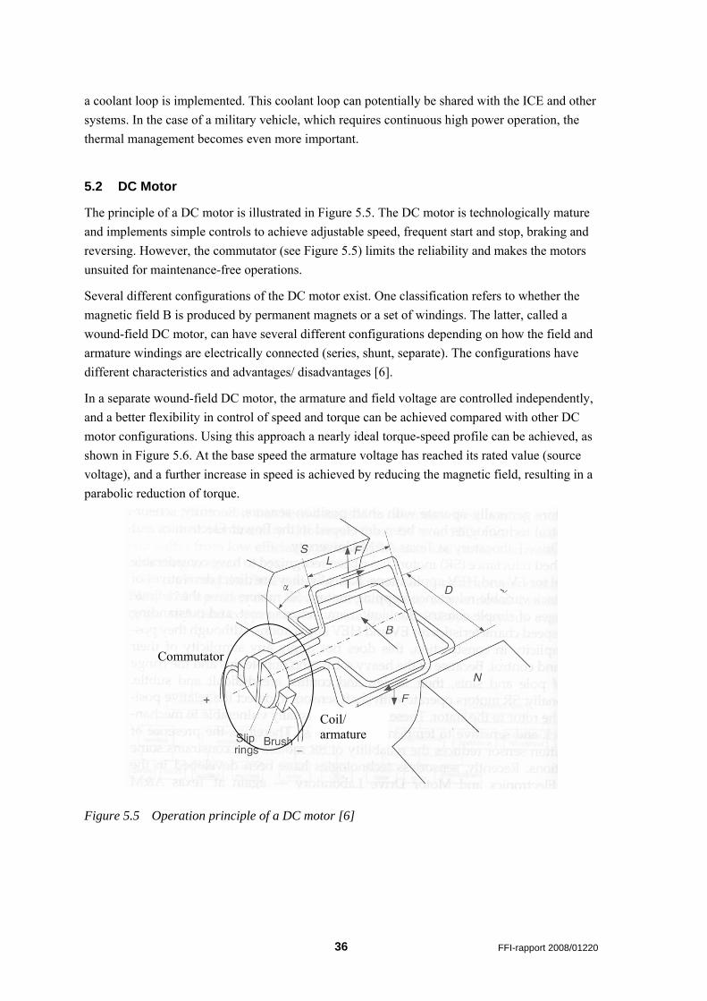
The importance of a high SR is further demonstrated in Figure 5.4. The different curves represent the required motor power rating normalized with regard to vehicle weight.
Figure 5.3 Tractive effort versus vehicle speed with different SRs (x) and motor power for a 10 tons series HEV. The required tractive effort to achieve a certain off-road gradeability is also indicated [22]
Figure 5.4 Typical power requirements for a military vehicle for different situations [23]
Another important aspect of electric motors for traction applications is thermal management. As the relationship between power/ torque and volume (torque/ power density) is required to be high,
FFI-rapport 2008/01220 35
a coolant loop is implemented. This coolant loop can potentially be shared with the ICE and other systems. In the case of a military vehicle, which requires continuous high power operation, the thermal management becomes even more important.
5.2 DC Motor
The principle of a DC motor is illustrated in Figure 5.5. The DC motor is technologically mature and implements simple controls to achieve adjustable speed, frequent start and stop, braking and reversing. However, the commutator (see Figure 5.5) limits the reliability and makes the motors unsuited for maintenance-free operations.
Several different configurations of the DC motor exist. One classification refers to whether the magnetic field B is produced by permanent magnets or a set of windings. The latter, called a wound-field DC motor, can have several different configurations depending on how the field and armature windings are electrically connected (series, shunt, separate). The configurations have different characteristics and advantages/ disadvantages [6].
In a separate wound-field DC motor, the armature and field voltage are controlled independently, and a better flexibility in control of speed and torque can be achieved compared with other DC motor configurations. Using this approach a nearly ideal torque-speed profile can be achieved, as shown in Figure 5.6. At the base speed the armature voltage has reached its rated value (source voltage), and a further increase in speed is achieved by reducing the magnetic field, resulting in a parabolic reduction of torque.
Commutator
Coil/ armature
Figure 5.5 Operation principle of a DC motor [6]
36 FFI-rapport 2008/01220
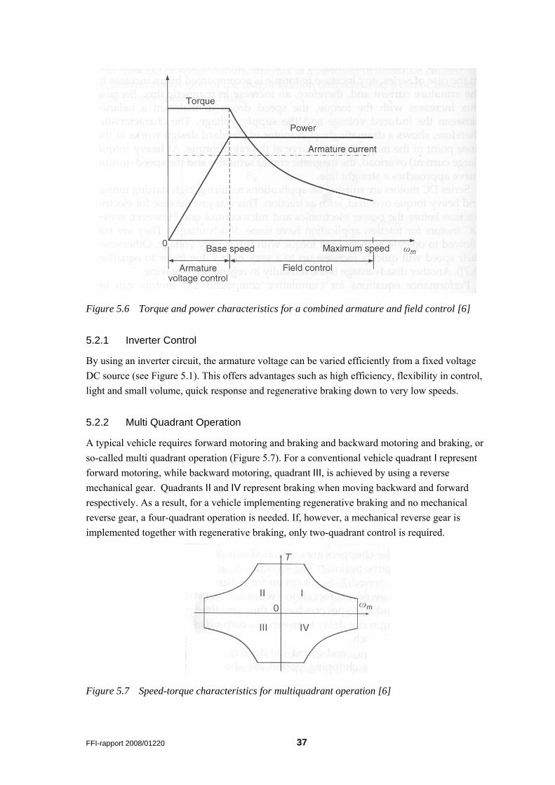
Figure 5.6 Torque and power characteristics for a combined armature and field control [6]
5.2.1 Inverter Control
By using an inverter circuit, the armature voltage can be varied efficiently from a fixed voltage DC source (see Figure 5.1). This offers advantages such as high efficiency, flexibility in control, light and small volume, quick response and regenerative braking down to very low speeds.
5.2.2 Multi Quadrant Operation
A typical vehicle requires forward motoring and braking and backward motoring and braking, or so-called multi quadrant operation (Figure 5.7). For a conventional vehicle quadrant I represent forward motoring, while backward motoring, quadrant III, is achieved by using a reverse mechanical gear. Quadrants II and IV represent braking when moving backward and forward respectively. As a result, for a vehicle implementing regenerative braking and no mechanical reverse gear, a four-quadrant operation is needed. If, however, a mechanical reverse gear is implemented together with regenerative braking, only two-quadrant control is required.
Figure 5.7 Speed-torque characteristics for multiquadrant operation [6]
FFI-rapport 2008/01220 37
5.3 Induction Motor
The induction motor is the most technological mature commutatorless electric motor and offers advantages such as low weight and volume, low cost and high efficiency.
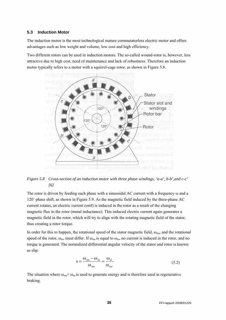
Two different rotors can be used in induction motors. The so-called wound-rotor is, however, less attractive due to high cost, need of maintenance and lack of robustness. Therefore an induction motor typically refers to a motor with a squirrel-cage rotor, as shown in Figure 5.8.
Figure 5.8 Cross-section of an induction motor with three phase windings, ‘a-a’, b-b’,and c-c’ [6]
The rotor is driven by feeding each phase with a sinusoidal AC current with a frequency ω and a 120˚ phase shift, as shown in Figure 5.9. As the magnetic field induced by the three-phase AC current rotates, an electric current (emf) is induced in the rotor as a result of the changing magnetic flux in the rotor (mutal inductance). This induced electric current again generates a magnetic field in the rotor, which will try to align with the rotating magnetic field of the stator, thus creating a rotor torque.
In order for this to happen, the rotational speed of the stator magnetic field, ωms, and the rotational speed of the rotor, ωm, must differ. If ωms is equal to ωm, no current is induced in the rotor, and no torque is generated. The normalized differential angular velocity of the stator and rotor is known as slip:
ms
sl
ms
mmssωω
=ω
ω−ω= (5.2)
The situation where ωms< ωm is used to generate energy and is therefore used in regenerative braking.
38 FFI-rapport 2008/01220
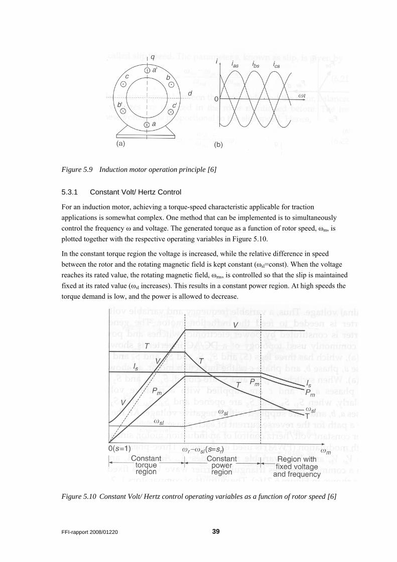
Figure 5.9 Induction motor operation principle [6]
5.3.1 Constant Volt/ Hertz Control
For an induction motor, achieving a torque-speed characteristic applicable for traction applications is somewhat complex. One method that can be implemented is to simultaneously control the frequency ω and voltage. The generated torque as a function of rotor speed, ωm, is plotted together with the respective operating variables in Figure 5.10.
In the constant torque region the voltage is increased, while the relative difference in speed between the rotor and the rotating magnetic field is kept constant (ωsl=const). When the voltage reaches its rated value, the rotating magnetic field, ωms, is controlled so that the slip is maintained fixed at its rated value (ωsl increases). This results in a constant power region. At high speeds the torque demand is low, and the power is allowed to decrease.
Figure 5.10 Constant Volt/ Hertz control operating variables as a function of rotor speed [6]
FFI-rapport 2008/01220 39
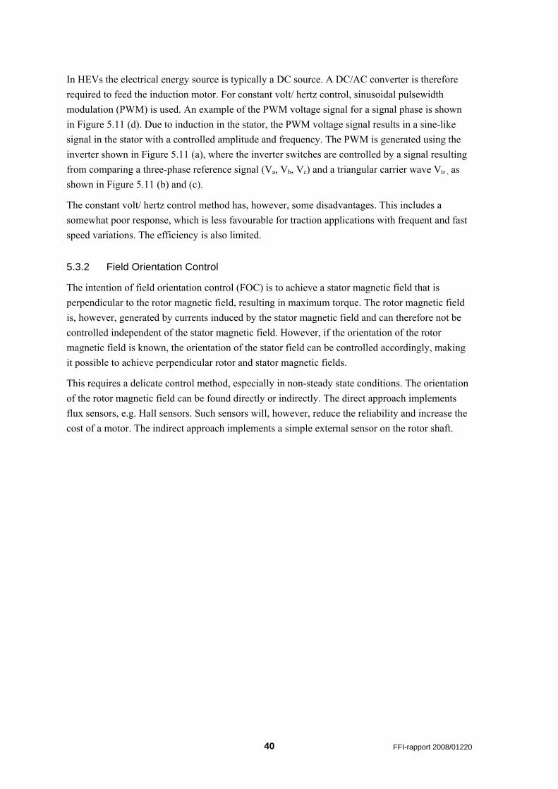
In HEVs the electrical energy source is typically a DC source. A DC/AC converter is therefore required to feed the induction motor. For constant volt/ hertz control, sinusoidal pulsewidth modulation (PWM) is used. An example of the PWM voltage signal for a signal phase is shown in Figure 5.11 (d). Due to induction in the stator, the PWM voltage signal results in a sine-like signal in the stator with a controlled amplitude and frequency. The PWM is generated using the inverter shown in Figure 5.11 (a), where the inverter switches are controlled by a signal resulting from comparing a three-phase reference signal (Va, Vb, Vc) and a triangular carrier wave Vtr , as shown in Figure 5.11 (b) and (c).
The constant volt/ hertz control method has, however, some disadvantages. This includes a somewhat poor response, which is less favourable for traction applications with frequent and fast speed variations. The efficiency is also limited.
5.3.2 Field Orientation Control
The intention of field orientation control (FOC) is to achieve a stator magnetic field that is perpendicular to the rotor magnetic field, resulting in maximum torque. The rotor magnetic field is, however, generated by currents induced by the stator magnetic field and can therefore not be controlled independent of the stator magnetic field. However, if the orientation of the rotor magnetic field is known, the orientation of the stator field can be controlled accordingly, making it possible to achieve perpendicular rotor and stator magnetic fields.
This requires a delicate control method, especially in non-steady state conditions. The orientation of the rotor magnetic field can be found directly or indirectly. The direct approach implements flux sensors, e.g. Hall sensors. Such sensors will, however, reduce the reliability and increase the cost of a motor. The indirect approach implements a simple external sensor on the rotor shaft.
40 FFI-rapport 2008/01220
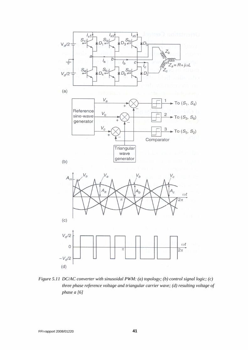
Figure 5.11 DC/AC converter with sinusoidal PWM: (a) topology; (b) control signal logic; (c) three phase reference voltage and triangular carrier wave; (d) resulting voltage of phase a [6]
FFI-rapport 2008/01220 41
5.4 Permanent Magnetic Brush-Less DC Motor Drives
These motors, which are very popular for HEVs, use permanent magnets as the field excitation mechanism. Compared to the conventional DC motors (Figure 5.5) the rotor in this case is the permanent magnet, which means that a commutator is not needed (brush-less). Advantages include high power density, high speed, and high operating efficiency.
The operating principle of a brush-less DC (BLDC) motor is shown in Figure 5.12. Based on the field orientation sensors H1, H2 and H3, the digital signal processing (DSP) controller supplies switching signals to the power converter.
Figure 5.12 Operating principle of a brush-less DC (BLDC) motor [6]
The BLDC motors are categorized as either surface mounted or interior mounted permanent magnet motors, and this refers to how the permanent magnets are mounted on the rotor. The surface mounted type is easier to fabricate, but the maximum speed is limited due to the centrifugal forces.
Stator type is another category which is characterized by the shape of the back EMF (electro magnetic force) waveforms, namely trapezoidal and sinusoidal.
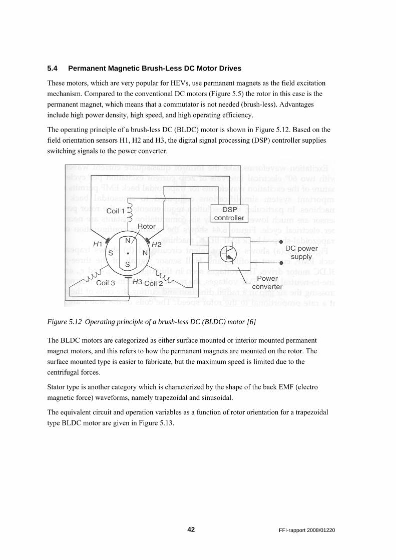
The equivalent circuit and operation variables as a function of rotor orientation for a trapezoidal type BLDC motor are given in Figure 5.13.
42 FFI-rapport 2008/01220
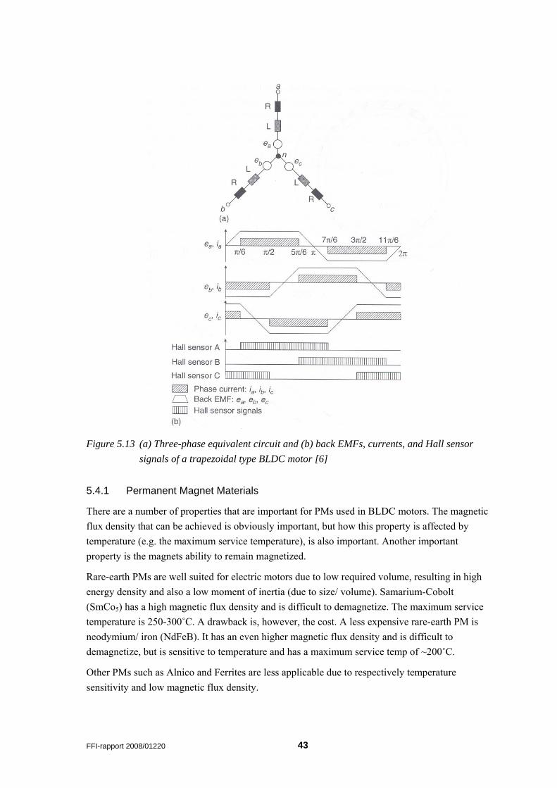
Figure 5.13 (a) Three-phase equivalent circuit and (b) back EMFs, currents, and Hall sensor signals of a trapezoidal type BLDC motor [6]
5.4.1 Permanent Magnet Materials
There are a number of properties that are important for PMs used in BLDC motors. The magnetic flux density that can be achieved is obviously important, but how this property is affected by temperature (e.g. the maximum service temperature), is also important. Another important property is the magnets ability to remain magnetized.
Rare-earth PMs are well suited for electric motors due to low required volume, resulting in high energy density and also a low moment of inertia (due to size/ volume). Samarium-Cobolt (SmCo5) has a high magnetic flux density and is difficult to demagnetize. The maximum service temperature is 250-300˚C. A drawback is, however, the cost. A less expensive rare-earth PM is neodymium/ iron (NdFeB). It has an even higher magnetic flux density and is difficult to demagnetize, but is sensitive to temperature and has a maximum service temp of ~200˚C.
Other PMs such as Alnico and Ferrites are less applicable due to respectively temperature sensitivity and low magnetic flux density.
FFI-rapport 2008/01220 43
5.4.2 Control and Performance Analysis of BLDC Motors
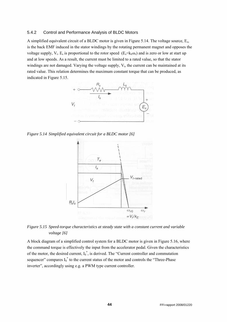
A simplified equivalent circuit of a BLDC motor is given in Figure 5.14. The voltage source, Es, is the back EMF induced in the stator windings by the rotating permanent magnet and opposes the voltage supply, Vt. Es is proportional to the rotor speed (Es=kEωr) and is zero or low at start up and at low speeds. As a result, the current must be limited to a rated value, so that the stator windings are not damaged. Varying the voltage supply, Vt, the current can be maintained at its rated value. This relation determines the maximum constant torque that can be produced, as indicated in Figure 5.15.
Figure 5.14 Simplified equivalent circuit for a BLDC motor [6]
Figure 5.15 Speed-torque characteristics at steady state with a constant current and variable voltage [6]
A block diagram of a simplified control system for a BLDC motor is given in Figure 5.16, where the command torque is effectively the input from the accelerator pedal. Given the characteristics of the motor, the desired current, IS
*, is derived. The “Current controller and commutation sequencer” compares IS
* to the current status of the motor and controls the “Three-Phase inverter”, accordingly using e.g. a PWM type current controller.
44 FFI-rapport 2008/01220
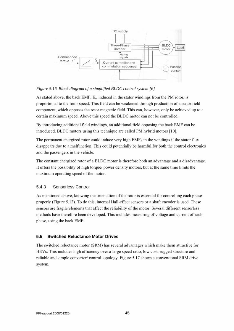
Figure 5.16 Block diagram of a simplified BLDC control system [6]
As stated above, the back EMF, Es, induced in the stator windings from the PM rotor, is proportional to the rotor speed. This field can be weakened through production of a stator field component, which opposes the rotor magnetic field. This can, however, only be achieved up to a certain maximum speed. Above this speed the BLDC motor can not be controlled.
By introducing additional field windings, an additional field opposing the back EMF can be introduced. BLDC motors using this technique are called PM hybrid motors [10].
The permanent energized rotor could induce very high EMFs in the windings if the stator flux disappears due to a malfunction. This could potentially be harmful for both the control electronics and the passengers in the vehicle.
The constant energized rotor of a BLDC motor is therefore both an advantage and a disadvantage. It offers the possibility of high torque/ power density motors, but at the same time limits the maximum operating speed of the motor.
5.4.3 Sensorless Control
As mentioned above, knowing the orientation of the rotor is essential for controlling each phase properly (Figure 5.12). To do this, internal Hall-effect sensors or a shaft encoder is used. These sensors are fragile elements that affect the reliability of the motor. Several different sensorless methods have therefore been developed. This includes measuring of voltage and current of each phase, using the back EMF.
5.5 Switched Reluctance Motor Drives
The switched reluctance motor (SRM) has several advantages which make them attractive for HEVs. This includes high efficiency over a large speed ratio, low cost, rugged structure and reliable and simple converter/ control topology. Figure 5.17 shows a conventional SRM drive system.
FFI-rapport 2008/01220 45
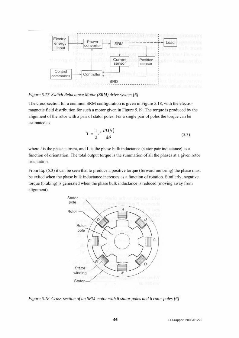
Figure 5.17 Switch Reluctance Motor (SRM) drive system [6]
The cross-section for a common SRM configuration is given in Figure 5.18, with the electro-magnetic field distribution for such a motor given in Figure 5.19. The torque is produced by the alignment of the rotor with a pair of stator poles. For a single pair of poles the torque can be estimated as
( )θθ
ddLiT 2
21
= (5.3)
where i is the phase current, and L is the phase bulk inductance (stator pair inductance) as a function of orientation. The total output torque is the summation of all the phases at a given rotor orientation.
From Eq. (5.3) it can be seen that to produce a positive torque (forward motoring) the phase must be exited when the phase bulk inductance increases as a function of rotation. Similarly, negative torque (braking) is generated when the phase bulk inductance is reduced (moving away from alignment).
Figure 5.18 Cross-section of an SRM motor with 8 stator poles and 6 rotor poles [6]
46 FFI-rapport 2008/01220
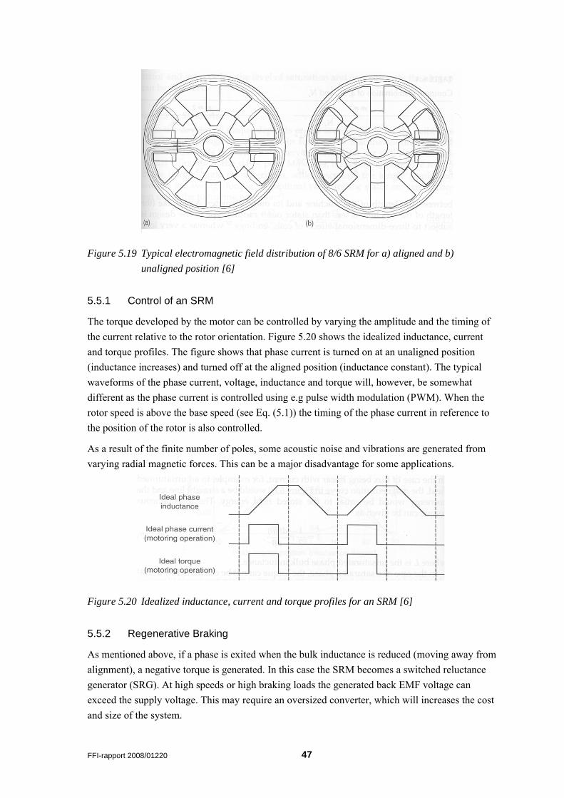
Figure 5.19 Typical electromagnetic field distribution of 8/6 SRM for a) aligned and b) unaligned position [6]
5.5.1 Control of an SRM
The torque developed by the motor can be controlled by varying the amplitude and the timing of the current relative to the rotor orientation. Figure 5.20 shows the idealized inductance, current and torque profiles. The figure shows that phase current is turned on at an unaligned position (inductance increases) and turned off at the aligned position (inductance constant). The typical waveforms of the phase current, voltage, inductance and torque will, however, be somewhat different as the phase current is controlled using e.g pulse width modulation (PWM). When the rotor speed is above the base speed (see Eq. (5.1)) the timing of the phase current in reference to the position of the rotor is also controlled.
As a result of the finite number of poles, some acoustic noise and vibrations are generated from varying radial magnetic forces. This can be a major disadvantage for some applications.
Figure 5.20 Idealized inductance, current and torque profiles for an SRM [6]
5.5.2 Regenerative Braking
As mentioned above, if a phase is exited when the bulk inductance is reduced (moving away from alignment), a negative torque is generated. In this case the SRM becomes a switched reluctance generator (SRG). At high speeds or high braking loads the generated back EMF voltage can exceed the supply voltage. This may require an oversized converter, which will increases the cost and size of the system.
FFI-rapport 2008/01220 47
5.5.3 Sensorless Control
In order to control the motor, the position of the rotor must be known. Similarly to other electric motors, it is desirable not to be dependant on fragile sensors which can affect the reliability of the motor. A number of different sensorless control methods have been developed.
5.6 In-hub Electric Motors
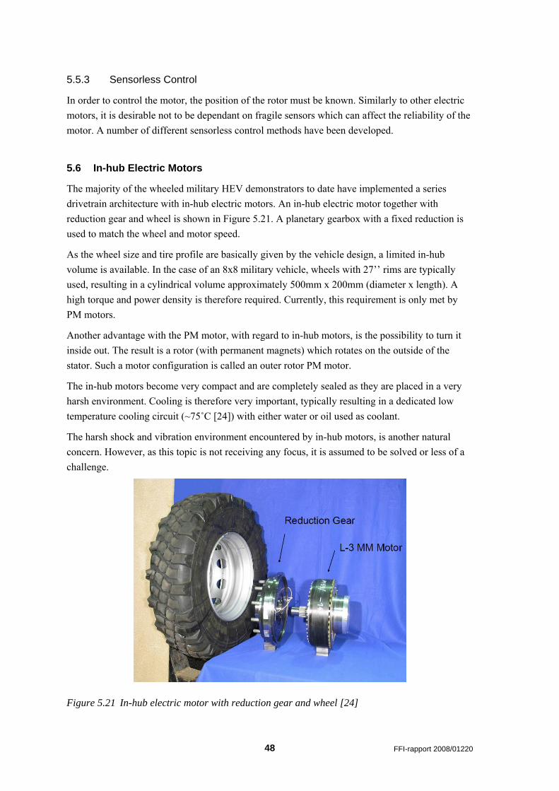
The majority of the wheeled military HEV demonstrators to date have implemented a series drivetrain architecture with in-hub electric motors. An in-hub electric motor together with reduction gear and wheel is shown in Figure 5.21. A planetary gearbox with a fixed reduction is used to match the wheel and motor speed.
As the wheel size and tire profile are basically given by the vehicle design, a limited in-hub volume is available. In the case of an 8x8 military vehicle, wheels with 27’’ rims are typically used, resulting in a cylindrical volume approximately 500mm x 200mm (diameter x length). A high torque and power density is therefore required. Currently, this requirement is only met by PM motors.
Another advantage with the PM motor, with regard to in-hub motors, is the possibility to turn it inside out. The result is a rotor (with permanent magnets) which rotates on the outside of the stator. Such a motor configuration is called an outer rotor PM motor.
The in-hub motors become very compact and are completely sealed as they are placed in a very harsh environment. Cooling is therefore very important, typically resulting in a dedicated low temperature cooling circuit (~75˚C [24]) with either water or oil used as coolant.
The harsh shock and vibration environment encountered by in-hub motors, is another natural concern. However, as this topic is not receiving any focus, it is assumed to be solved or less of a challenge.
Figure 5.21 In-hub electric motor with reduction gear and wheel [24]
48 FFI-rapport 2008/01220
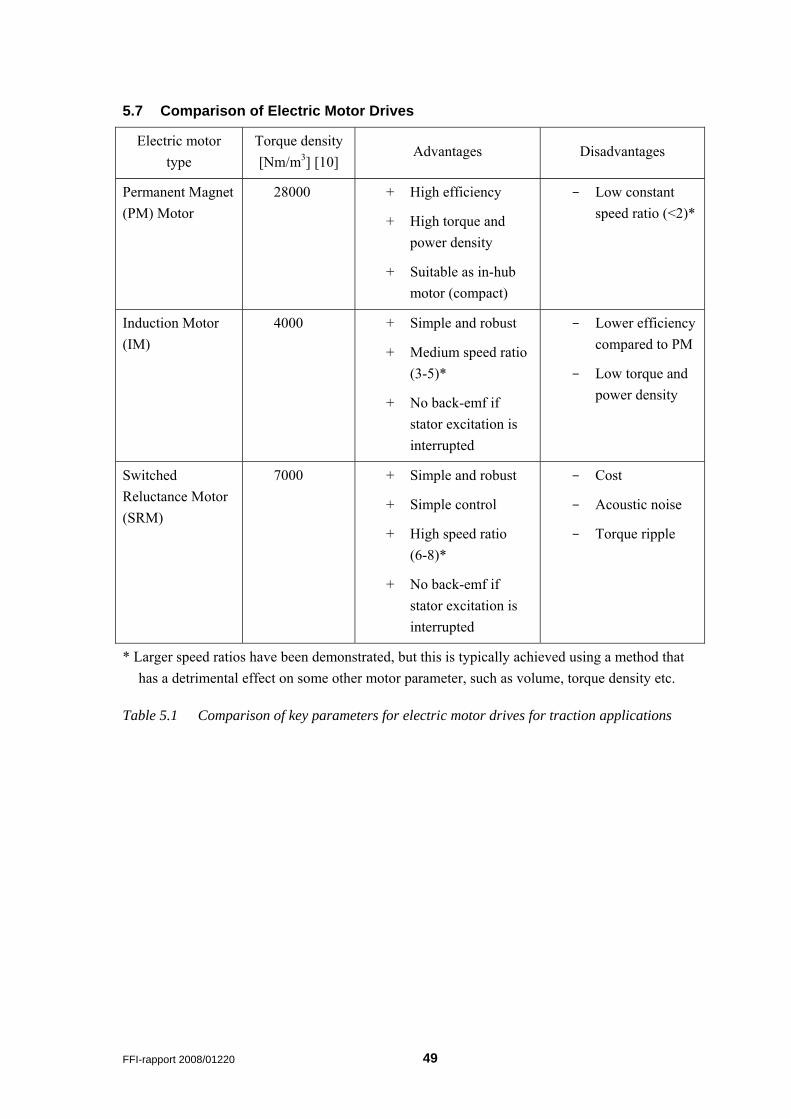
5.7 Comparison of Electric Motor Drives
Electric motor type
Torque density [Nm/m3] [10]
Advantages Disadvantages
Permanent Magnet (PM) Motor
28000 + High efficiency
+ High torque and power density
+ Suitable as in-hub motor (compact)
- Low constant speed ratio (<2)*
Induction Motor (IM)
4000 + Simple and robust
+ Medium speed ratio (3-5)*
+ No back-emf if stator excitation is interrupted
- Lower efficiency compared to PM
- Low torque and power density
Switched Reluctance Motor (SRM)
7000 + Simple and robust
+ Simple control
+ High speed ratio (6-8)*
+ No back-emf if stator excitation is interrupted
- Cost
- Acoustic noise
- Torque ripple
* Larger speed ratios have been demonstrated, but this is typically achieved using a method that has a detrimental effect on some other motor parameter, such as volume, torque density etc.
Table 5.1 Comparison of key parameters for electric motor drives for traction applications
FFI-rapport 2008/01220 49
6 Power Electronics The term “power electronics” refers to the high voltage and high current systems used to control the electric motor and manage the energy storage system (e.g. battery). In the block diagram given in Figure 5.1, the inverters and bidirectional DC-DC converters are the power electronics systems.
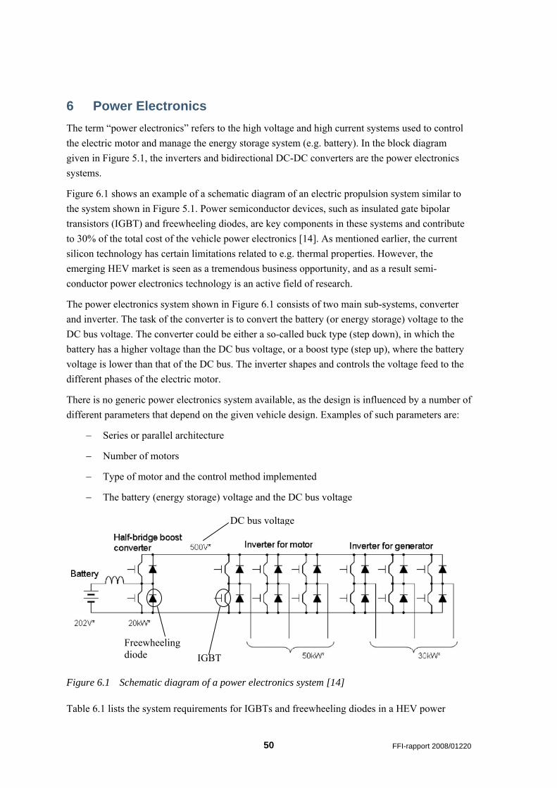
Figure 6.1 shows an example of a schematic diagram of an electric propulsion system similar to the system shown in Figure 5.1. Power semiconductor devices, such as insulated gate bipolar transistors (IGBT) and freewheeling diodes, are key components in these systems and contribute to 30% of the total cost of the vehicle power electronics [14]. As mentioned earlier, the current silicon technology has certain limitations related to e.g. thermal properties. However, the emerging HEV market is seen as a tremendous business opportunity, and as a result semi-conductor power electronics technology is an active field of research.
The power electronics system shown in Figure 6.1 consists of two main sub-systems, converter and inverter. The task of the converter is to convert the battery (or energy storage) voltage to the DC bus voltage. The converter could be either a so-called buck type (step down), in which the battery has a higher voltage than the DC bus voltage, or a boost type (step up), where the battery voltage is lower than that of the DC bus. The inverter shapes and controls the voltage feed to the different phases of the electric motor.
There is no generic power electronics system available, as the design is influenced by a number of different parameters that depend on the given vehicle design. Examples of such parameters are:
− Series or parallel architecture
− Number of motors
− Type of motor and the control method implemented
− The battery (energy storage) voltage and the DC bus voltage
DC bus voltage
Figure 6.1 Schematic diagram of a power electronics system [14]
Table 6.1 lists the system requirements for IGBTs and freewheeling diodes in a HEV power
IGBT Freewheeling diode
50 FFI-rapport 2008/01220
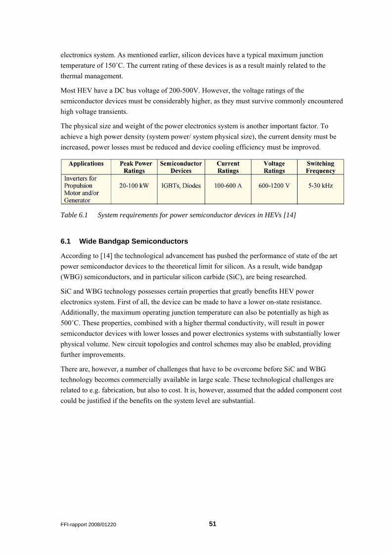
electronics system. As mentioned earlier, silicon devices have a typical maximum junction temperature of 150˚C. The current rating of these devices is as a result mainly related to the thermal management.
Most HEV have a DC bus voltage of 200-500V. However, the voltage ratings of the semiconductor devices must be considerably higher, as they must survive commonly encountered high voltage transients.
The physical size and weight of the power electronics system is another important factor. To achieve a high power density (system power/ system physical size), the current density must be increased, power losses must be reduced and device cooling efficiency must be improved.
Table 6.1 System requirements for power semiconductor devices in HEVs [14]
6.1 Wide Bandgap Semiconductors
According to [14] the technological advancement has pushed the performance of state of the art power semiconductor devices to the theoretical limit for silicon. As a result, wide bandgap (WBG) semiconductors, and in particular silicon carbide (SiC), are being researched.
SiC and WBG technology possesses certain properties that greatly benefits HEV power electronics system. First of all, the device can be made to have a lower on-state resistance. Additionally, the maximum operating junction temperature can also be potentially as high as 500˚C. These properties, combined with a higher thermal conductivity, will result in power semiconductor devices with lower losses and power electronics systems with substantially lower physical volume. New circuit topologies and control schemes may also be enabled, providing further improvements.
There are, however, a number of challenges that have to be overcome before SiC and WBG technology becomes commercially available in large scale. These technological challenges are related to e.g. fabrication, but also to cost. It is, however, assumed that the added component cost could be justified if the benefits on the system level are substantial.
FFI-rapport 2008/01220 51
7 Energy Storage and Management The task of the energy storage in an HEV is to store energy from regenerative braking and excessive energy generated by the ICE/ generator. This stored energy is again released during high power demands (acceleration etc.) or during electric only operation, e.g. silent mobility, silent watch etc.
Several types of energy storage have been proposed for HEVs. These are, so far, chemical batteries, ultra-capacitors and flywheels. An important parameter for the energy storage is the specific energy (kWh/kg), sometimes also referred to as energy density, which is defined as the energy capacity divided by the energy storage weight. Similarly, the specific (peak) power (kW/kg) is another important parameter. The efficiency, cycle and calendar life, maintenance requirements, cost, environmental friendliness and safety are other important aspects.
In Figure 2.5 the specific power for different energy storages is plotted as a function of the specific energy. The figure shows that the different types of energy storage have very different characteristics. Ultra-capacitors, for instance, can supply high peak power (kW), but the amount of energy (kWh) stored is limited. A battery, however, has somewhat opposite characteristics with a much lower peak power, but a higher amount of stored energy. The operating cycle of the vehicle is therefore paramount when determining the type and size of the energy storage. For example, an HEV that is designed to operate for a certain distance in electric-only mode and a HEV city bus, which start and stops regularly, will require very different energy storage systems.
7.1 Batteries
Battery types that are suitable for vehicle applications include lead acid, nickel-metal hydrid (NiMH), and lithium-ion (Li-ion). However, more than 30 different battery systems are being studied for EV and HEV applications. Most vehicles tested and marked to date in 2006 used NiMH [25].
The practical specific energy and power of a battery is a function of the chemical reactions in the battery cell, the weight and the total volume of the battery cell. For a lead-acid battery, which is a well established technology, only 26% of the total weight is directly involved in producing electrical energy. The remaining weight is made up of solvents, current collectors and leads, and less active reactants. Furthermore the characteristics of a battery are a function of the discharge rate and the remaining energy stored in the battery.
In this context the state-of-charge (SOC) is important and is basically equivalent to a fuel gauge with e.g. a SOC of 100% representing a fully charged battery. However, the principle of capacity is complicated by the fact that the battery capacity, in ampere-hours (Ah), is different for different discharge rates, as indicated in Figure 7.1. As a result, batteries are often specified with an ampere-hours value along with a current rate. For example, a battery labelled 100 Ah at a C5 rate has a capacity of 100 ampere-hours at a 5 hour discharge rate, resulting in a discharge current of 20A.
52 FFI-rapport 2008/01220

Figure 7.1 Discharge characteristics of a lead-acid battery at different discharge currents [6]
The energy or power losses, due to internal resistance in the battery, during discharge and charging are a function of SOC. Figure 7.2 shows the typical battery charge and discharge efficiency as a function of SOC. For an HEV, where the battery is typically dimensioned according to the maximum required power, the battery operation control unit will operate the battery in the middle 5-10% in order to enhance efficiency, avoid temperature rises due to energy loss, and greatly increase the cycle and calendar life [25]. This means that for an HEV the energy capacity of the battery is in effect 90-95% higher than what is basically needed to meet the required driving cycle.
In the case where the HEV needs to operate in all-electric mode for a substantial range or time (silent mobility or silent watch), a large percentage of the battery capacity will be utilized9. Combining the typical HEV operating mode, where only 5-10% of SOC is utilized, with a deep discharge (large percentage of SOC is utilized) operating mode in one battery is a major challenge, where cycle life becomes an important issue. This is in effect one of the main factors holding back the commercialization of plug-in HEVs, and is assumed to complicate the combination of silent watch/ silent mobility and normal HE operating mode for military vehicles. The use of an auxiliary power unit (APU), in the form of a small ICE/ generator or a fuel cell (2-10 kW), can potentially assist the battery in silent watch mode preventing deep discharge.
In Table 7.1 a summary is given of characteristics of state-of-the-art batteries for HEVs and EVs. It is apparent that the batteries for HEVs are quite different from batteries for EVs. As mentioned earlier, HEVs are designed to have a high specific power. Comparing the specific power (W/kg 95% efficiency) for EVs and HEVs, it can be seen that the batteries intended for HEVs have a specific power that is considerably higher (60-500%) than batteries intended for EVs. Similarly, batteries intended for EVs have a specific energy (Wh/kg at C3) and capacity (Ah) that is higher than HEV batteries. The usable percentage of SOC is also given for the HEV batteries.
A military HEV that requires a substantial all-electric capacity, will require batteries similar to plug-in HEVs. The trade off between specific energy, specific power, and cycle life is very important in this context. 9 This operation mode resembles in effect the operating mode of an EV.
FFI-rapport 2008/01220 53
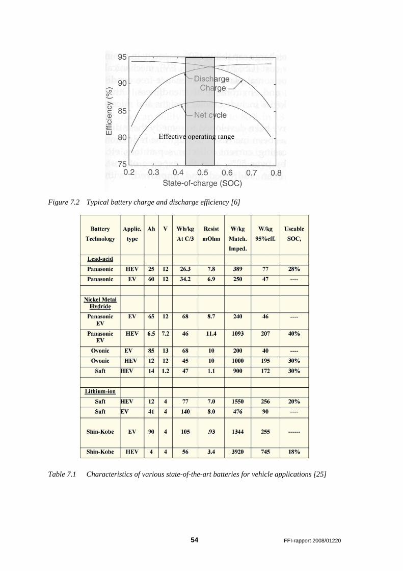
Effective operating range
Figure 7.2 Typical battery charge and discharge efficiency [6]
Table 7.1 Characteristics of various state-of-the-art batteries for vehicle applications [25]
54 FFI-rapport 2008/01220
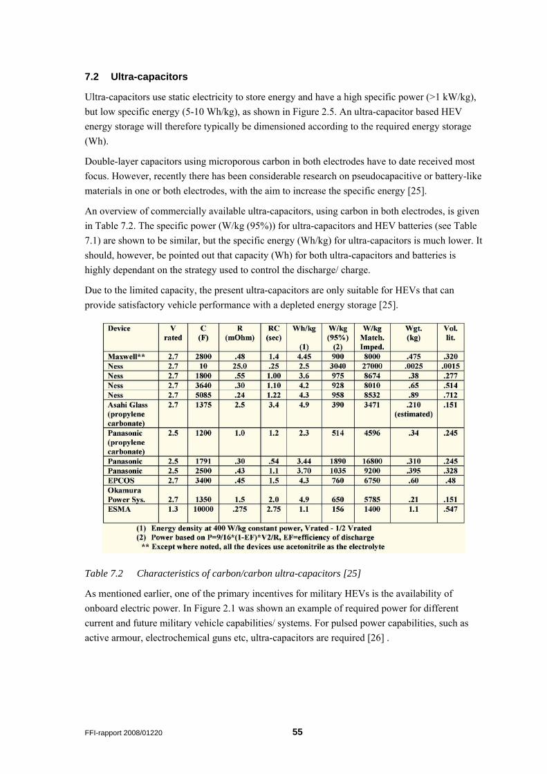
7.2 Ultra-capacitors
Ultra-capacitors use static electricity to store energy and have a high specific power (>1 kW/kg), but low specific energy (5-10 Wh/kg), as shown in Figure 2.5. An ultra-capacitor based HEV energy storage will therefore typically be dimensioned according to the required energy storage (Wh).
Double-layer capacitors using microporous carbon in both electrodes have to date received most focus. However, recently there has been considerable research on pseudocapacitive or battery-like materials in one or both electrodes, with the aim to increase the specific energy [25].
An overview of commercially available ultra-capacitors, using carbon in both electrodes, is given in Table 7.2. The specific power (W/kg (95%)) for ultra-capacitors and HEV batteries (see Table 7.1) are shown to be similar, but the specific energy (Wh/kg) for ultra-capacitors is much lower. It should, however, be pointed out that capacity (Wh) for both ultra-capacitors and batteries is highly dependant on the strategy used to control the discharge/ charge.
Due to the limited capacity, the present ultra-capacitors are only suitable for HEVs that can provide satisfactory vehicle performance with a depleted energy storage [25].
Table 7.2 Characteristics of carbon/carbon ultra-capacitors [25]
As mentioned earlier, one of the primary incentives for military HEVs is the availability of onboard electric power. In Figure 2.1 was shown an example of required power for different current and future military vehicle capabilities/ systems. For pulsed power capabilities, such as active armour, electrochemical guns etc, ultra-capacitors are required [26] .
FFI-rapport 2008/01220 55
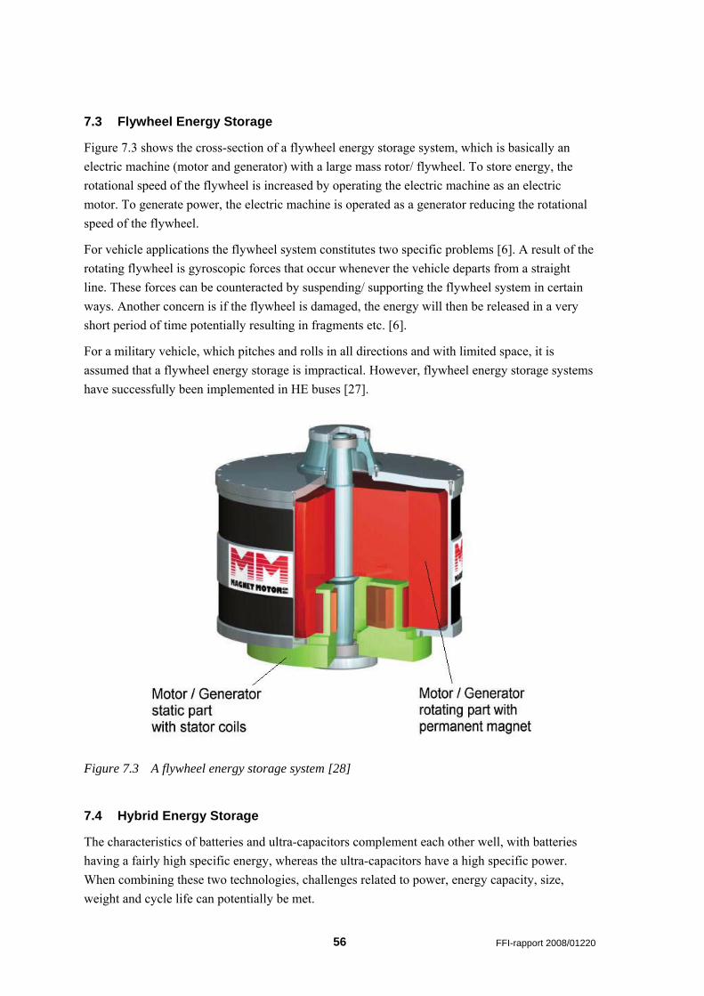
7.3 Flywheel Energy Storage
Figure 7.3 shows the cross-section of a flywheel energy storage system, which is basically an electric machine (motor and generator) with a large mass rotor/ flywheel. To store energy, the rotational speed of the flywheel is increased by operating the electric machine as an electric motor. To generate power, the electric machine is operated as a generator reducing the rotational speed of the flywheel.
For vehicle applications the flywheel system constitutes two specific problems [6]. A result of the rotating flywheel is gyroscopic forces that occur whenever the vehicle departs from a straight line. These forces can be counteracted by suspending/ supporting the flywheel system in certain ways. Another concern is if the flywheel is damaged, the energy will then be released in a very short period of time potentially resulting in fragments etc. [6].
For a military vehicle, which pitches and rolls in all directions and with limited space, it is assumed that a flywheel energy storage is impractical. However, flywheel energy storage systems have successfully been implemented in HE buses [27].
Figure 7.3 A flywheel energy storage system [28]
7.4 Hybrid Energy Storage
The characteristics of batteries and ultra-capacitors complement each other well, with batteries having a fairly high specific energy, whereas the ultra-capacitors have a high specific power. When combining these two technologies, challenges related to power, energy capacity, size, weight and cycle life can potentially be met.
56 FFI-rapport 2008/01220
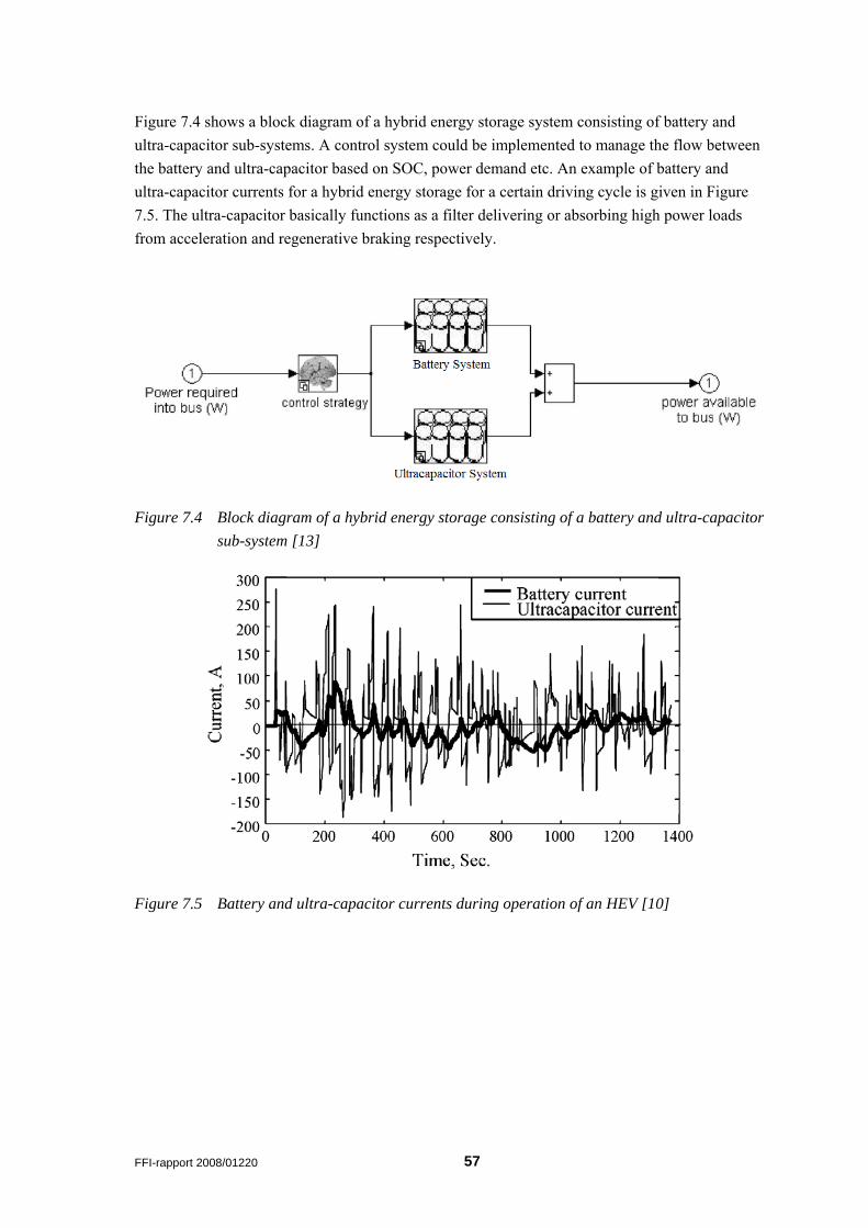
Figure 7.4 shows a block diagram of a hybrid energy storage system consisting of battery and ultra-capacitor sub-systems. A control system could be implemented to manage the flow between the battery and ultra-capacitor based on SOC, power demand etc. An example of battery and ultra-capacitor currents for a hybrid energy storage for a certain driving cycle is given in Figure 7.5. The ultra-capacitor basically functions as a filter delivering or absorbing high power loads from acceleration and regenerative braking respectively.
Figure 7.4 Block diagram of a hybrid energy storage consisting of a battery and ultra-capacitor sub-system [13]
Figure 7.5 Battery and ultra-capacitor currents during operation of an HEV [10]
FFI-rapport 2008/01220 57
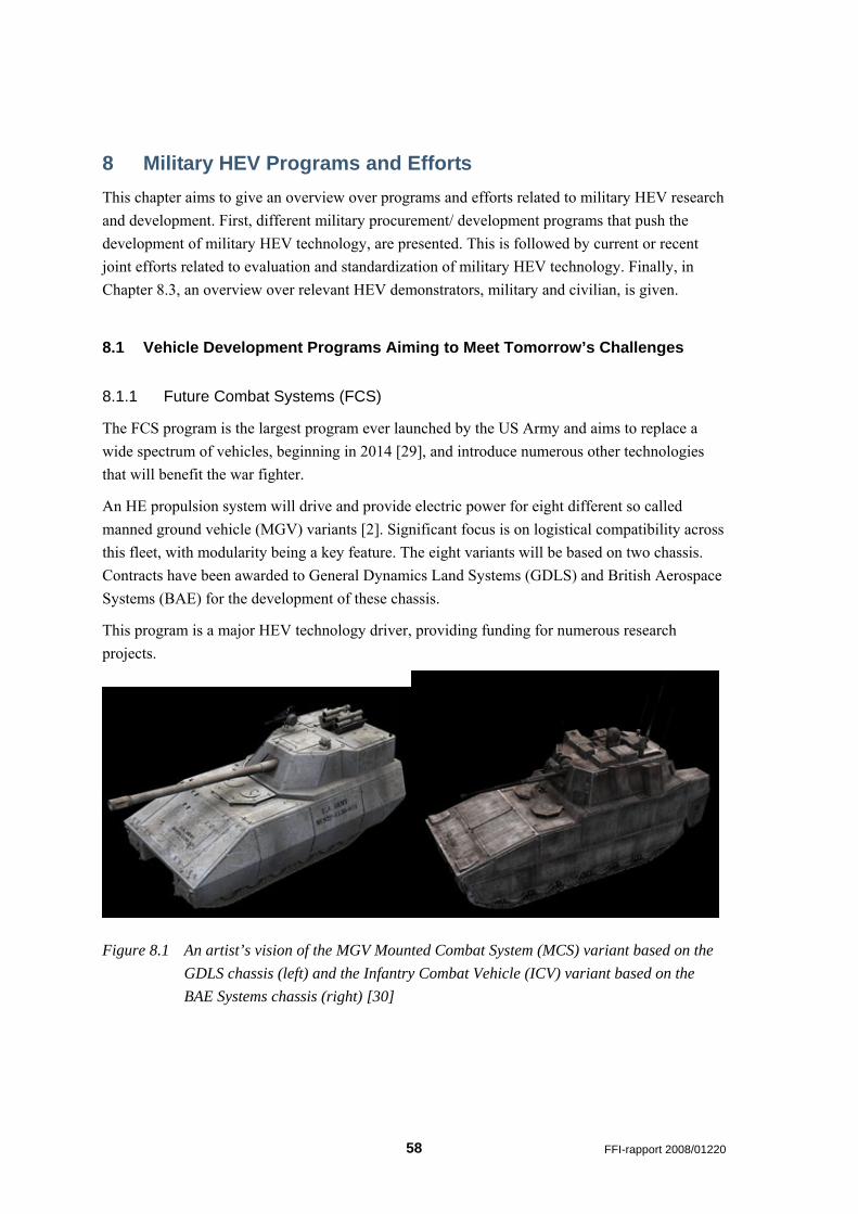
8 Military HEV Programs and Efforts This chapter aims to give an overview over programs and efforts related to military HEV research and development. First, different military procurement/ development programs that push the development of military HEV technology, are presented. This is followed by current or recent joint efforts related to evaluation and standardization of military HEV technology. Finally, in Chapter 8.3, an overview over relevant HEV demonstrators, military and civilian, is given.
8.1 Vehicle Development Programs Aiming to Meet Tomorrow’s Challenges
8.1.1 Future Combat Systems (FCS)
The FCS program is the largest program ever launched by the US Army and aims to replace a wide spectrum of vehicles, beginning in 2014 [29], and introduce numerous other technologies that will benefit the war fighter.
An HE propulsion system will drive and provide electric power for eight different so called manned ground vehicle (MGV) variants [2]. Significant focus is on logistical compatibility across this fleet, with modularity being a key feature. The eight variants will be based on two chassis. Contracts have been awarded to General Dynamics Land Systems (GDLS) and British Aerospace Systems (BAE) for the development of these chassis.
This program is a major HEV technology driver, providing funding for numerous research projects.
Figure 8.1 An artist’s vision of the MGV Mounted Combat System (MCS) variant based on the GDLS chassis (left) and the Infantry Combat Vehicle (ICV) variant based on the BAE Systems chassis (right) [30]
58 FFI-rapport 2008/01220
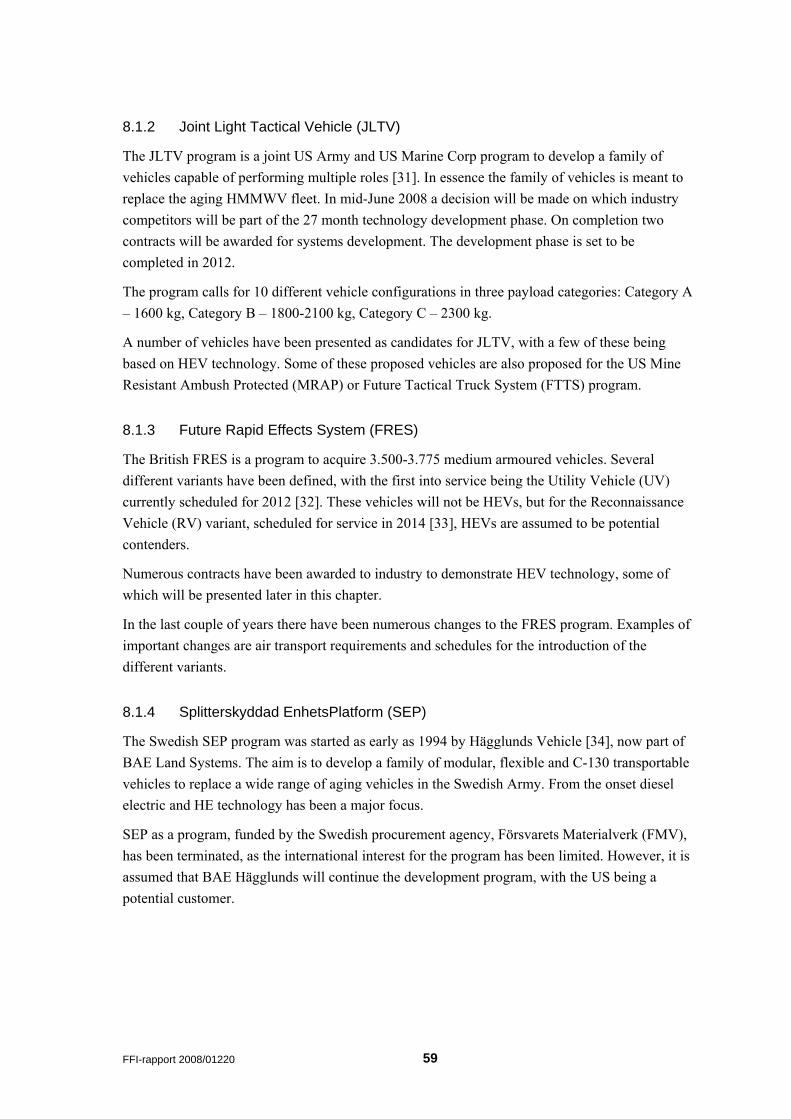
8.1.2 Joint Light Tactical Vehicle (JLTV)
The JLTV program is a joint US Army and US Marine Corp program to develop a family of vehicles capable of performing multiple roles [31]. In essence the family of vehicles is meant to replace the aging HMMWV fleet. In mid-June 2008 a decision will be made on which industry competitors will be part of the 27 month technology development phase. On completion two contracts will be awarded for systems development. The development phase is set to be completed in 2012.
The program calls for 10 different vehicle configurations in three payload categories: Category A – 1600 kg, Category B – 1800-2100 kg, Category C – 2300 kg.
A number of vehicles have been presented as candidates for JLTV, with a few of these being based on HEV technology. Some of these proposed vehicles are also proposed for the US Mine Resistant Ambush Protected (MRAP) or Future Tactical Truck System (FTTS) program.
8.1.3 Future Rapid Effects System (FRES)
The British FRES is a program to acquire 3.500-3.775 medium armoured vehicles. Several different variants have been defined, with the first into service being the Utility Vehicle (UV) currently scheduled for 2012 [32]. These vehicles will not be HEVs, but for the Reconnaissance Vehicle (RV) variant, scheduled for service in 2014 [33], HEVs are assumed to be potential contenders.
Numerous contracts have been awarded to industry to demonstrate HEV technology, some of which will be presented later in this chapter.
In the last couple of years there have been numerous changes to the FRES program. Examples of important changes are air transport requirements and schedules for the introduction of the different variants.
8.1.4 Splitterskyddad EnhetsPlatform (SEP)
The Swedish SEP program was started as early as 1994 by Hägglunds Vehicle [34], now part of BAE Land Systems. The aim is to develop a family of modular, flexible and C-130 transportable vehicles to replace a wide range of aging vehicles in the Swedish Army. From the onset diesel electric and HE technology has been a major focus.
SEP as a program, funded by the Swedish procurement agency, Försvarets Materialverk (FMV), has been terminated, as the international interest for the program has been limited. However, it is assumed that BAE Hägglunds will continue the development program, with the US being a potential customer.
FFI-rapport 2008/01220 59
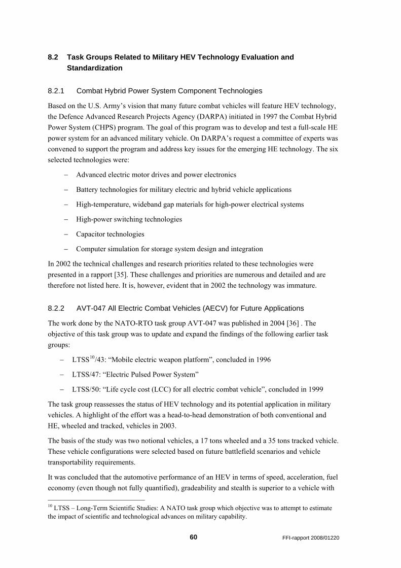
8.2 Task Groups Related to Military HEV Technology Evaluation and Standardization
8.2.1 Combat Hybrid Power System Component Technologies
Based on the U.S. Army’s vision that many future combat vehicles will feature HEV technology, the Defence Advanced Research Projects Agency (DARPA) initiated in 1997 the Combat Hybrid Power System (CHPS) program. The goal of this program was to develop and test a full-scale HE power system for an advanced military vehicle. On DARPA’s request a committee of experts was convened to support the program and address key issues for the emerging HE technology. The six selected technologies were:
− Advanced electric motor drives and power electronics
− Battery technologies for military electric and hybrid vehicle applications
− High-temperature, wideband gap materials for high-power electrical systems
− High-power switching technologies
− Capacitor technologies
− Computer simulation for storage system design and integration
In 2002 the technical challenges and research priorities related to these technologies were presented in a rapport [35]. These challenges and priorities are numerous and detailed and are therefore not listed here. It is, however, evident that in 2002 the technology was immature.
8.2.2 AVT-047 All Electric Combat Vehicles (AECV) for Future Applications
The work done by the NATO-RTO task group AVT-047 was published in 2004 [36] . The objective of this task group was to update and expand the findings of the following earlier task groups:
− LTSS10/43: “Mobile electric weapon platform”, concluded in 1996
− LTSS/47: “Electric Pulsed Power System”
− LTSS/50: “Life cycle cost (LCC) for all electric combat vehicle”, concluded in 1999
The task group reassesses the status of HEV technology and its potential application in military vehicles. A highlight of the effort was a head-to-head demonstration of both conventional and HE, wheeled and tracked, vehicles in 2003.
The basis of the study was two notional vehicles, a 17 tons wheeled and a 35 tons tracked vehicle. These vehicle configurations were selected based on future battlefield scenarios and vehicle transportability requirements.
It was concluded that the automotive performance of an HEV in terms of speed, acceleration, fuel economy (even though not fully quantified), gradeability and stealth is superior to a vehicle with
10 LTSS – Long-Term Scientific Studies: A NATO task group which objective was to attempt to estimate the impact of scientific and technological advances on military capability.
60 FFI-rapport 2008/01220
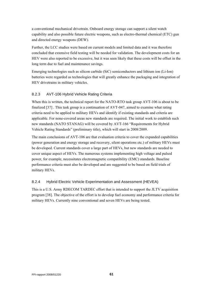
a conventional mechanical drivetrain. Onboard energy storage can support a silent watch capability and also possible future electric weapons, such as electro-thermal chemical (ETC) gun and directed energy weapons (DEW).
Further, the LCC studies were based on current models and limited data and it was therefore concluded that extensive field testing will be needed for validation. The development costs for an HEV were also reported to be excessive, but it was seen likely that these costs will be offset in the long term due to fuel and maintenance savings.
Emerging technologies such as silicon carbide (SiC) semiconductors and lithium ion (Li-Ion) batteries were regarded as technologies that will greatly enhance the packaging and integration of HEV drivetrains in military vehicles.
8.2.3 AVT-106 Hybrid Vehicle Rating Criteria
When this is written, the technical report for the NATO-RTO task group AVT-106 is about to be finalized [37] . This task group is a continuation of AVT-047, aimed to examine what rating criteria need to be applied to military HEVs and identify if existing standards and criteria are applicable. For none-covered areas new standards are required. The initial work to establish such new standards (NATO STANAG) will be covered by AVT-166 “Requirements for Hybrid Vehicle Rating Standards” (preliminary title), which will start in 2008/2009.
The main conclusions of AVT-106 are that evaluation criteria to cover the expanded capabilities (power generation and energy storage and recovery, silent operations etc.) of military HEVs must be developed. Current standards cover a large part of HEVs, but new standards are needed to cover unique aspect of HEVs. The numerous systems implementing high voltage and pulsed power, for example, necessitates electromagnetic compatibility (EMC) standards. Baseline performance criteria must also be developed and are suggested to be based on field trials of military HEVs.
8.2.4 Hybrid Electric Vehicle Experimentation and Assessment (HEVEA)
This is a U.S. Army RDECOM TARDEC effort that is intended to support the JLTV acquisition program [38]. The objective of the effort is to develop fuel economy and performance criteria for military HEVs. Currently nine conventional and seven HEVs are being tested.
FFI-rapport 2008/01220 61
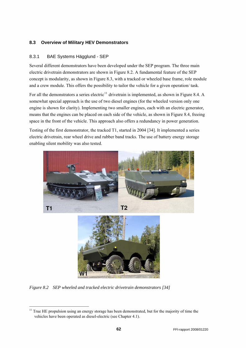
8.3 Overview of Military HEV Demonstrators
8.3.1 BAE Systems Hägglund - SEP
Several different demonstrators have been developed under the SEP program. The three main electric drivetrain demonstrators are shown in Figure 8.2. A fundamental feature of the SEP concept is modularity, as shown in Figure 8.3, with a tracked or wheeled base frame, role module and a crew module. This offers the possibility to tailor the vehicle for a given operation/ task.
For all the demonstrators a series electric11 drivetrain is implemented, as shown in Figure 8.4. A somewhat special approach is the use of two diesel engines (for the wheeled version only one engine is shown for clarity). Implementing two smaller engines, each with an electric generator, means that the engines can be placed on each side of the vehicle, as shown in Figure 8.4, freeing space in the front of the vehicle. This approach also offers a redundancy in power generation.
Testing of the first demonstrator, the tracked T1, started in 2004 [34]. It implemented a series electric drivetrain, rear wheel drive and rubber band tracks. The use of battery energy storage enabling silent mobility was also tested.
Figure 8.2 SEP wheeled and tracked electric drivetrain demonstrators [34]
11 True HE propulsion using an energy storage has been demonstrated, but for the majority of time the
vehicles have been operated as diesel-electric (see Chapter 4.1).
62 FFI-rapport 2008/01220
Figure 8.3 The modular SEP concept [34]
The next demonstrator was the wheeled W1. Testing of this demonstrator started in late 2004. It has a second generation series electric drivetrain with in-hub permanent magnet electric motors, with a two-speed reduction gear, supplied by MagTec (Magnetic Systems Technology) [39]. It is assumed that BAE Systems Hägglund and MagTec cooperate on the development of the entire electric drivetrain. The in-hub motors enable pivot turn.
The tracked T2 demonstrator, ready mid 2005, differed substantially from the T1. It had front wheel drive, as shown in Figure 8.4, and so-called second generation series electric drivetrain. It also had interchangeable crew/ mission module.
Diesel engine
Figure 8.4 SEP series HE drivetrain for tracked version (left) and wheeled version (right) [34]
At the 7th International All Electric Combat Vehicle Conference in 2007, Per Boeryd from FMV presented FMV’s conclusions on the electric drivetrain technology developed and demonstrated in SEP [40]. These conclusions were fairly critical compared with the majority of presentations held at the conference. The main features of the presentation will be discussed.
The SEP demonstrators have mainly been run as diesel-electric and not as true HEVs (see Chapter 4.1). The implementation an energy storage system, which enables features such as HE drive (with the potential of reduced energy consumption), power boost, silent operation is hard to justify due to the weight and volume of an energy storage system.
FFI-rapport 2008/01220 63
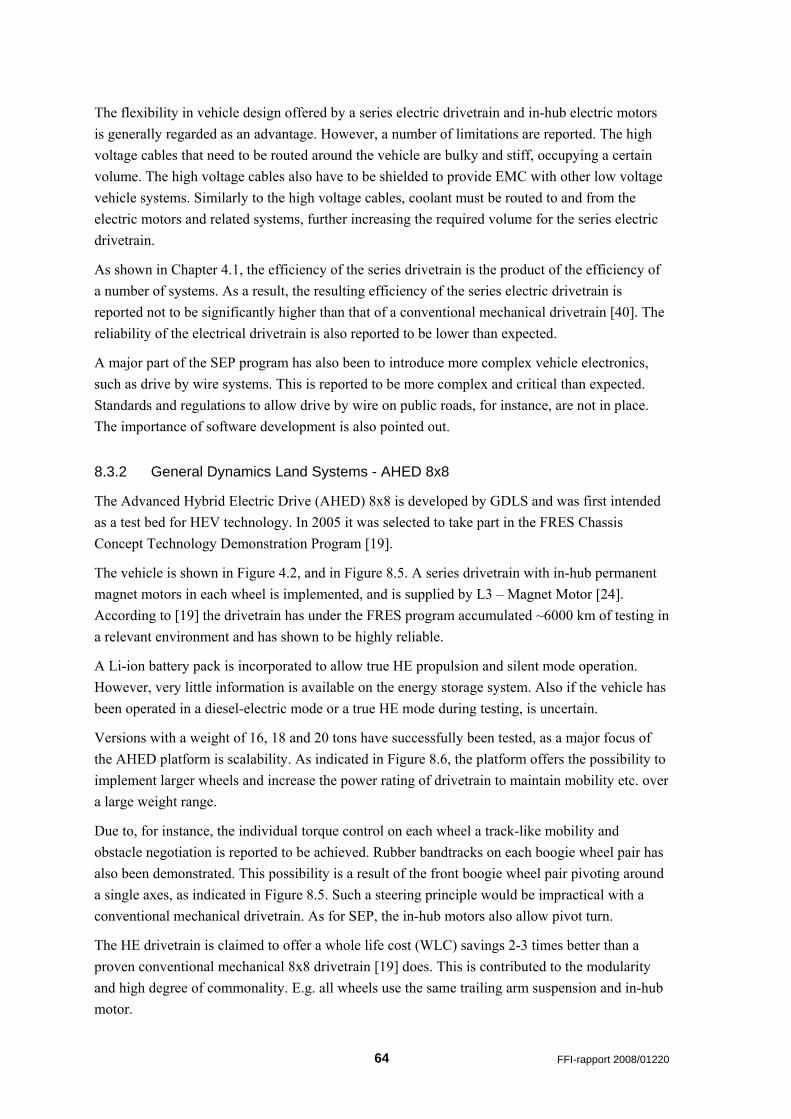
The flexibility in vehicle design offered by a series electric drivetrain and in-hub electric motors is generally regarded as an advantage. However, a number of limitations are reported. The high voltage cables that need to be routed around the vehicle are bulky and stiff, occupying a certain volume. The high voltage cables also have to be shielded to provide EMC with other low voltage vehicle systems. Similarly to the high voltage cables, coolant must be routed to and from the electric motors and related systems, further increasing the required volume for the series electric drivetrain.
As shown in Chapter 4.1, the efficiency of the series drivetrain is the product of the efficiency of a number of systems. As a result, the resulting efficiency of the series electric drivetrain is reported not to be significantly higher than that of a conventional mechanical drivetrain [40]. The reliability of the electrical drivetrain is also reported to be lower than expected.
A major part of the SEP program has also been to introduce more complex vehicle electronics, such as drive by wire systems. This is reported to be more complex and critical than expected. Standards and regulations to allow drive by wire on public roads, for instance, are not in place. The importance of software development is also pointed out.
8.3.2 General Dynamics Land Systems - AHED 8x8
The Advanced Hybrid Electric Drive (AHED) 8x8 is developed by GDLS and was first intended as a test bed for HEV technology. In 2005 it was selected to take part in the FRES Chassis Concept Technology Demonstration Program [19].
The vehicle is shown in Figure 4.2, and in Figure 8.5. A series drivetrain with in-hub permanent magnet motors in each wheel is implemented, and is supplied by L3 – Magnet Motor [24]. According to [19] the drivetrain has under the FRES program accumulated ~6000 km of testing in a relevant environment and has shown to be highly reliable.
A Li-ion battery pack is incorporated to allow true HE propulsion and silent mode operation. However, very little information is available on the energy storage system. Also if the vehicle has been operated in a diesel-electric mode or a true HE mode during testing, is uncertain.
Versions with a weight of 16, 18 and 20 tons have successfully been tested, as a major focus of the AHED platform is scalability. As indicated in Figure 8.6, the platform offers the possibility to implement larger wheels and increase the power rating of drivetrain to maintain mobility etc. over a large weight range.
Due to, for instance, the individual torque control on each wheel a track-like mobility and obstacle negotiation is reported to be achieved. Rubber bandtracks on each boogie wheel pair has also been demonstrated. This possibility is a result of the front boogie wheel pair pivoting around a single axes, as indicated in Figure 8.5. Such a steering principle would be impractical with a conventional mechanical drivetrain. As for SEP, the in-hub motors also allow pivot turn.
The HE drivetrain is claimed to offer a whole life cost (WLC) savings 2-3 times better than a proven conventional mechanical 8x8 drivetrain [19] does. This is contributed to the modularity and high degree of commonality. E.g. all wheels use the same trailing arm suspension and in-hub motor.
64 FFI-rapport 2008/01220
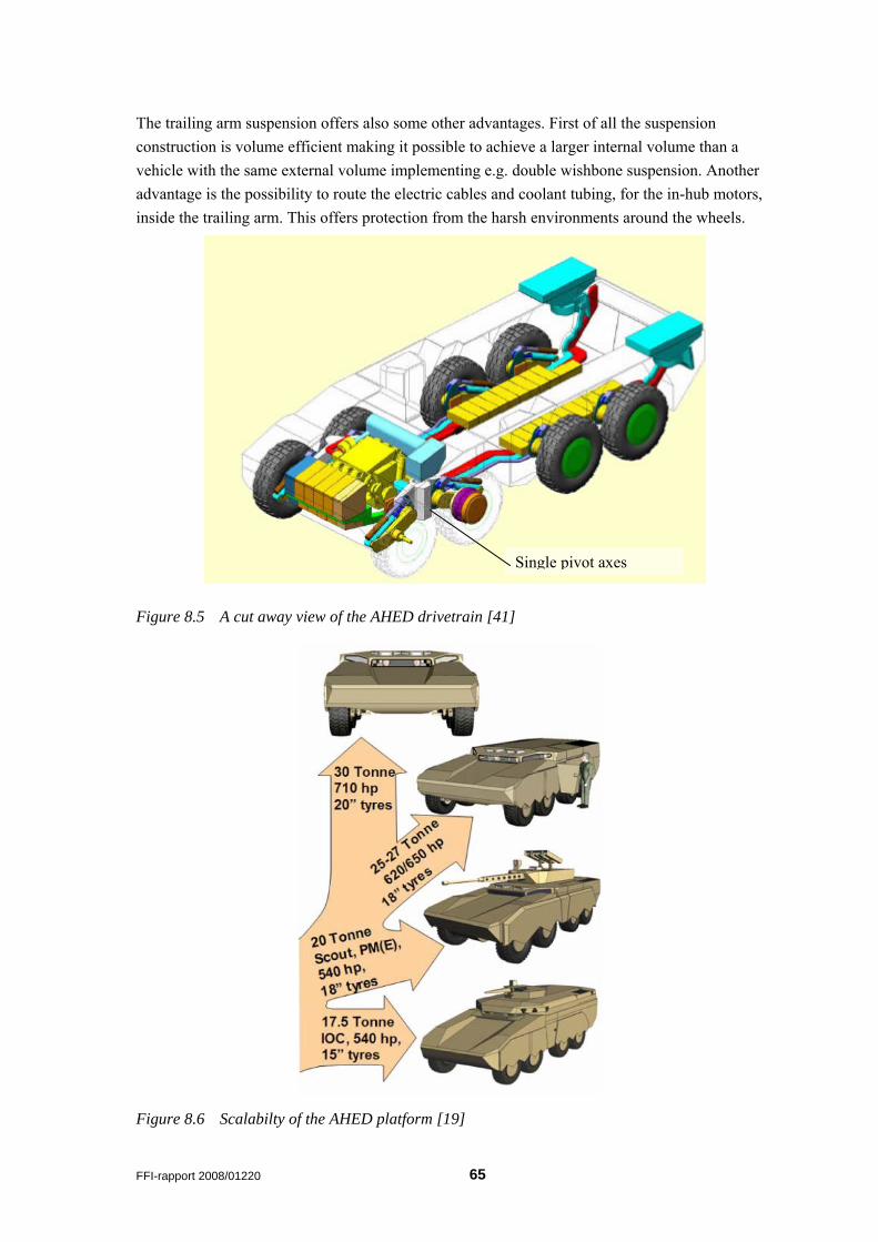
The trailing arm suspension offers also some other advantages. First of all the suspension construction is volume efficient making it possible to achieve a larger internal volume than a vehicle with the same external volume implementing e.g. double wishbone suspension. Another advantage is the possibility to route the electric cables and coolant tubing, for the in-hub motors, inside the trailing arm. This offers protection from the harsh environments around the wheels.
Single pivot axes
Figure 8.5 A cut away view of the AHED drivetrain [41]
Figure 8.6 Scalabilty of the AHED platform [19]
FFI-rapport 2008/01220 65
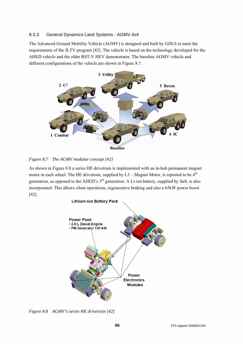
8.3.3 General Dynamics Land Systems - AGMV 4x4
The Advanced Ground Mobility Vehicle (AGMV) is designed and built by GDLS to meet the requirements of the JLTV program [42]. The vehicle is based on the technology developed for the AHED vehicle and the older RST-V HEV demonstrator. The baseline AGMV vehicle and different configurations of the vehicle are shown in Figure 8.7.
Figure 8.7 The AGMV modular concept [42]
As shown in Figure 8.8 a series HE drivetrain is implemented with an in-hub permanent magnet motor in each wheel. The HE drivetrain, supplied by L3 – Magnet Motor, is reported to be 4th generation, as opposed to the AHED’s 3rd generation. A Li-ion battery, supplied by Saft, is also incorporated. This allows silent operations, regenerative braking and also a 65kW power boost [42].
Figure 8.8 AGMV’s series HE drivetrain [42]
66 FFI-rapport 2008/01220
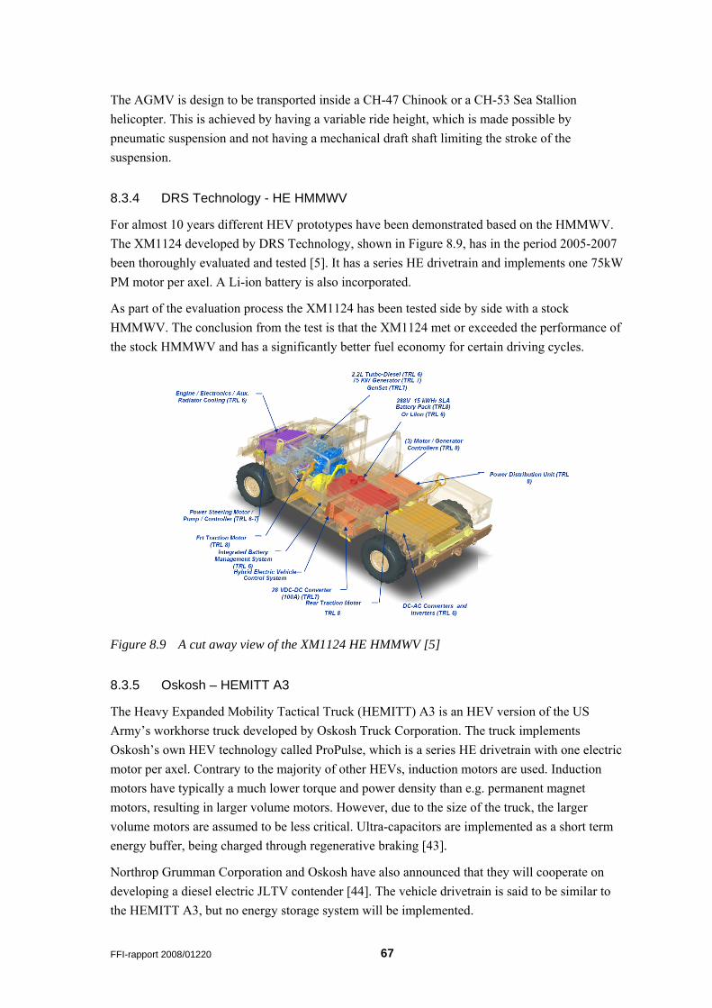
The AGMV is design to be transported inside a CH-47 Chinook or a CH-53 Sea Stallion helicopter. This is achieved by having a variable ride height, which is made possible by pneumatic suspension and not having a mechanical draft shaft limiting the stroke of the suspension.
8.3.4 DRS Technology - HE HMMWV
For almost 10 years different HEV prototypes have been demonstrated based on the HMMWV. The XM1124 developed by DRS Technology, shown in Figure 8.9, has in the period 2005-2007 been thoroughly evaluated and tested [5]. It has a series HE drivetrain and implements one 75kW PM motor per axel. A Li-ion battery is also incorporated.
As part of the evaluation process the XM1124 has been tested side by side with a stock HMMWV. The conclusion from the test is that the XM1124 met or exceeded the performance of the stock HMMWV and has a significantly better fuel economy for certain driving cycles.
Figure 8.9 A cut away view of the XM1124 HE HMMWV [5]
8.3.5 Oskosh – HEMITT A3
The Heavy Expanded Mobility Tactical Truck (HEMITT) A3 is an HEV version of the US Army’s workhorse truck developed by Oskosh Truck Corporation. The truck implements Oskosh’s own HEV technology called ProPulse, which is a series HE drivetrain with one electric motor per axel. Contrary to the majority of other HEVs, induction motors are used. Induction motors have typically a much lower torque and power density than e.g. permanent magnet motors, resulting in larger volume motors. However, due to the size of the truck, the larger volume motors are assumed to be less critical. Ultra-capacitors are implemented as a short term energy buffer, being charged through regenerative braking [43].
Northrop Grumman Corporation and Oskosh have also announced that they will cooperate on developing a diesel electric JLTV contender [44]. The vehicle drivetrain is said to be similar to the HEMITT A3, but no energy storage system will be implemented.
FFI-rapport 2008/01220 67
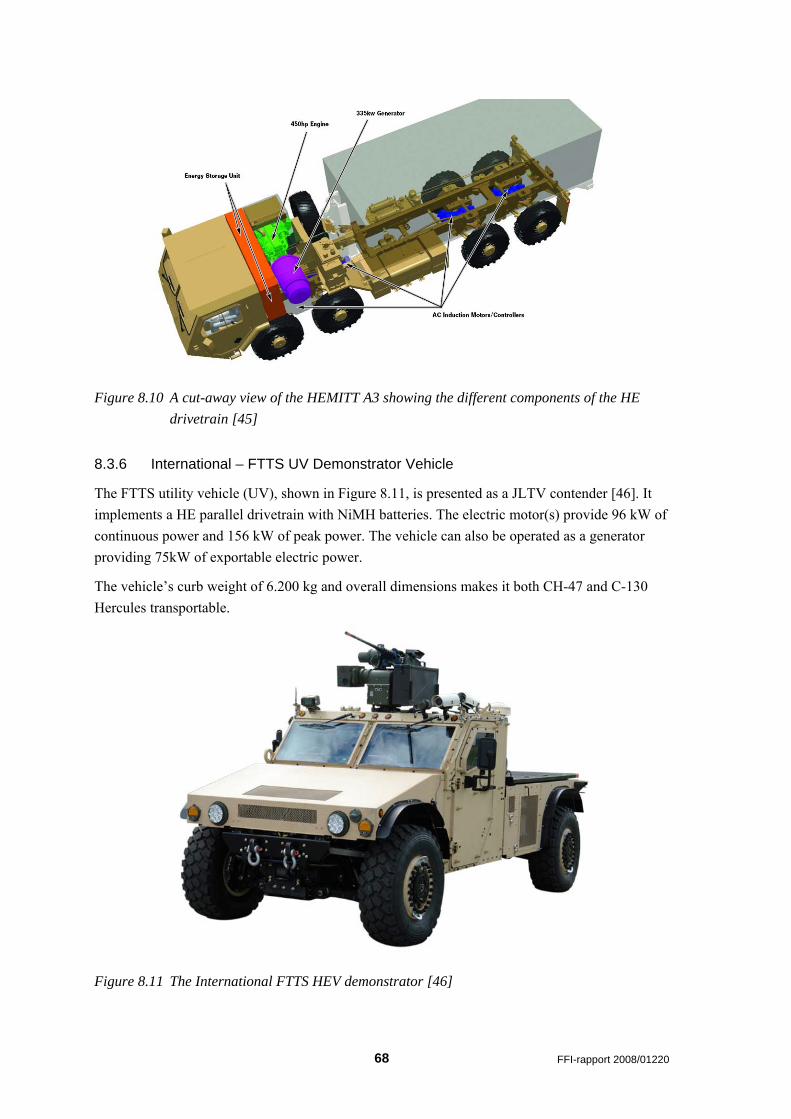
Figure 8.10 A cut-away view of the HEMITT A3 showing the different components of the HE drivetrain [45]
8.3.6 International – FTTS UV Demonstrator Vehicle
The FTTS utility vehicle (UV), shown in Figure 8.11, is presented as a JLTV contender [46]. It implements a HE parallel drivetrain with NiMH batteries. The electric motor(s) provide 96 kW of continuous power and 156 kW of peak power. The vehicle can also be operated as a generator providing 75kW of exportable electric power.
The vehicle’s curb weight of 6.200 kg and overall dimensions makes it both CH-47 and C-130 Hercules transportable.
Figure 8.11 The International FTTS HEV demonstrator [46]
68 FFI-rapport 2008/01220
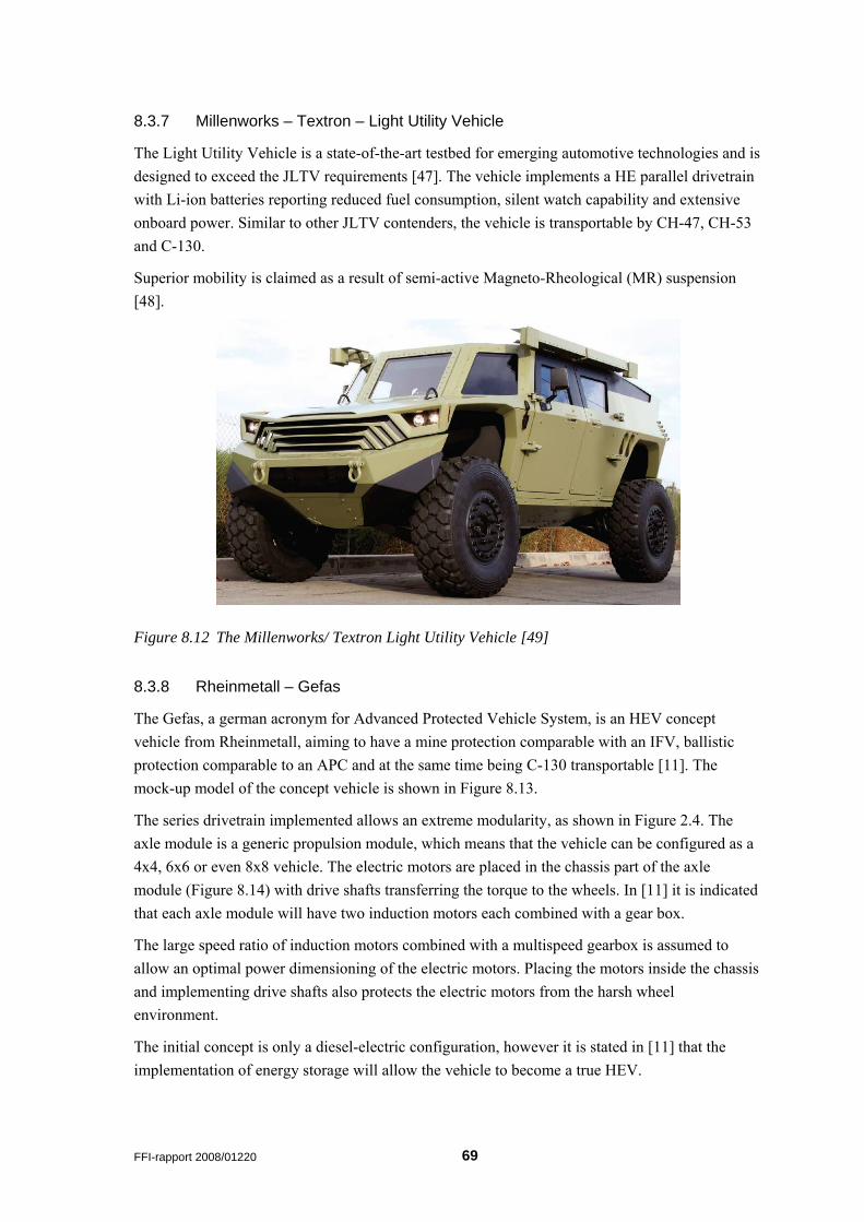
8.3.7 Millenworks – Textron – Light Utility Vehicle
The Light Utility Vehicle is a state-of-the-art testbed for emerging automotive technologies and is designed to exceed the JLTV requirements [47]. The vehicle implements a HE parallel drivetrain with Li-ion batteries reporting reduced fuel consumption, silent watch capability and extensive onboard power. Similar to other JLTV contenders, the vehicle is transportable by CH-47, CH-53 and C-130.
Superior mobility is claimed as a result of semi-active Magneto-Rheological (MR) suspension [48].
Figure 8.12 The Millenworks/ Textron Light Utility Vehicle [49]
8.3.8 Rheinmetall – Gefas
The Gefas, a german acronym for Advanced Protected Vehicle System, is an HEV concept vehicle from Rheinmetall, aiming to have a mine protection comparable with an IFV, ballistic protection comparable to an APC and at the same time being C-130 transportable [11]. The mock-up model of the concept vehicle is shown in Figure 8.13.
The series drivetrain implemented allows an extreme modularity, as shown in Figure 2.4. The axle module is a generic propulsion module, which means that the vehicle can be configured as a 4x4, 6x6 or even 8x8 vehicle. The electric motors are placed in the chassis part of the axle module (Figure 8.14) with drive shafts transferring the torque to the wheels. In [11] it is indicated that each axle module will have two induction motors each combined with a gear box.
The large speed ratio of induction motors combined with a multispeed gearbox is assumed to allow an optimal power dimensioning of the electric motors. Placing the motors inside the chassis and implementing drive shafts also protects the electric motors from the harsh wheel environment.
The initial concept is only a diesel-electric configuration, however it is stated in [11] that the implementation of energy storage will allow the vehicle to become a true HEV.
FFI-rapport 2008/01220 69
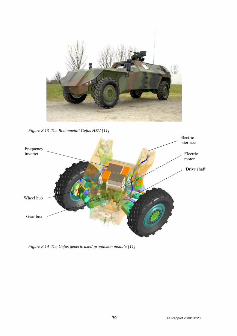
Figure 8.13 The Rheinmetall Gefas HEV [11]
Figure 8.14 The Gefas generic axel/ propulsion module [11]
Frequency inverter
Wheel hub
Gear box
Electric motor
Electric interface
Drive shaft
70 FFI-rapport 2008/01220
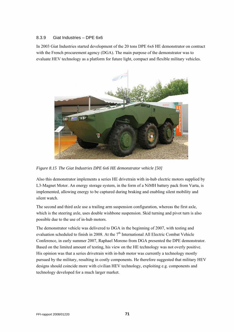
8.3.9 Giat Industries – DPE 6x6
In 2003 Giat Industries started development of the 20 tons DPE 6x6 HE demonstrator on contract with the French procurement agency (DGA). The main purpose of the demonstrator was to evaluate HEV technology as a platform for future light, compact and flexible military vehicles.
Figure 8.15 The Giat Industries DPE 6x6 HE demonstrator vehicle [50]
Also this demonstrator implements a series HE drivetrain with in-hub electric motors supplied by L3-Magnet Motor. An energy storage system, in the form of a NiMH battery pack from Varta, is implemented, allowing energy to be captured during braking and enabling silent mobility and silent watch.
The second and third axle use a trailing arm suspension configuration, whereas the first axle, which is the steering axle, uses double wishbone suspension. Skid turning and pivot turn is also possible due to the use of in-hub motors.
The demonstrator vehicle was delivered to DGA in the beginning of 2007, with testing and evaluation scheduled to finish in 2008. At the 7th International All Electric Combat Vehicle Conference, in early summer 2007, Raphael Moreno from DGA presented the DPE demonstrator. Based on the limited amount of testing, his view on the HE technology was not overly positive. His opinion was that a series drivetrain with in-hub motor was currently a technology mostly pursued by the military, resulting in costly components. He therefore suggested that military HEV designs should coincide more with civilian HEV technology, exploiting e.g. components and technology developed for a much larger market.
FFI-rapport 2008/01220 71
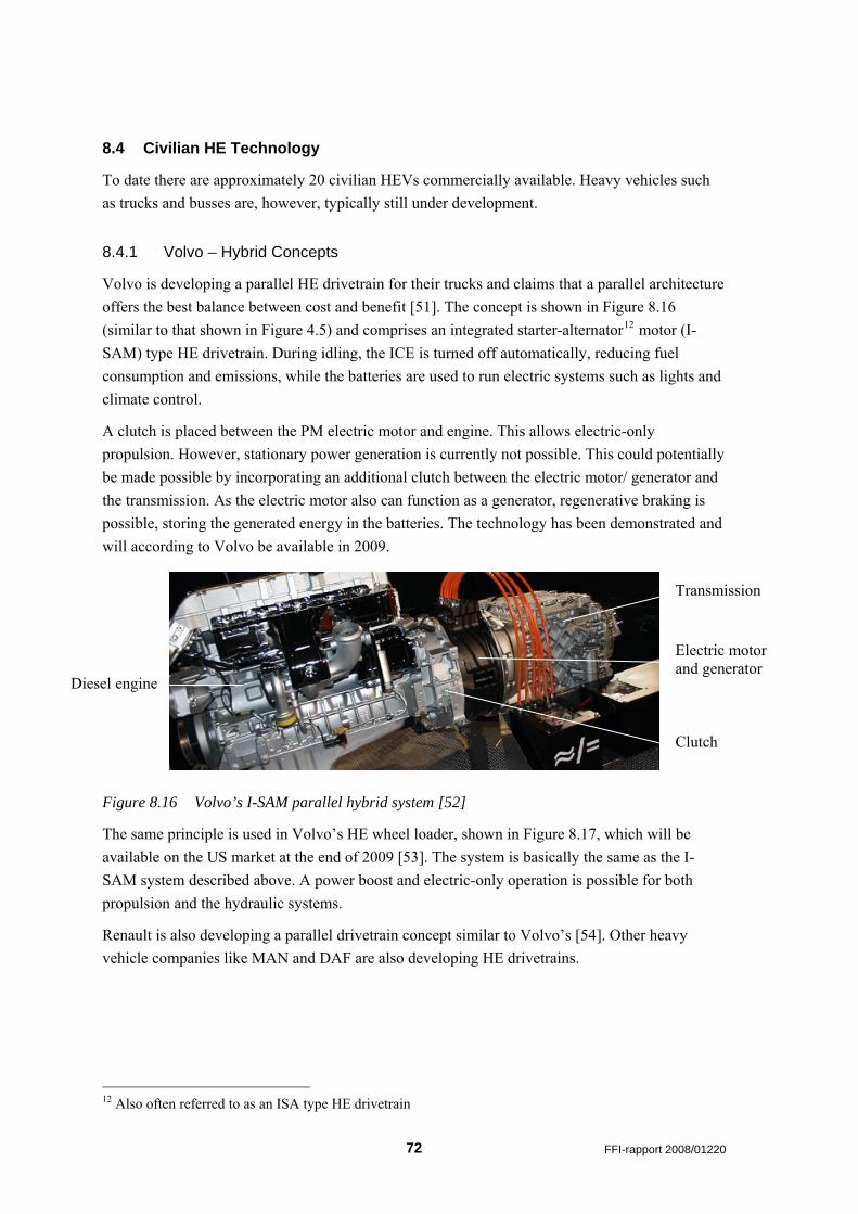
8.4 Civilian HE Technology
To date there are approximately 20 civilian HEVs commercially available. Heavy vehicles such as trucks and busses are, however, typically still under development.
8.4.1 Volvo – Hybrid Concepts
Volvo is developing a parallel HE drivetrain for their trucks and claims that a parallel architecture offers the best balance between cost and benefit [51]. The concept is shown in Figure 8.16 (similar to that shown in Figure 4.5) and comprises an integrated starter-alternator12 motor (I-SAM) type HE drivetrain. During idling, the ICE is turned off automatically, reducing fuel consumption and emissions, while the batteries are used to run electric systems such as lights and climate control.
A clutch is placed between the PM electric motor and engine. This allows electric-only propulsion. However, stationary power generation is currently not possible. This could potentially be made possible by incorporating an additional clutch between the electric motor/ generator and the transmission. As the electric motor also can function as a generator, regenerative braking is possible, storing the generated energy in the batteries. The technology has been demonstrated and will according to Volvo be available in 2009.
Transmission
Electric motor and generator
Diesel engine
Clutch
Figure 8.16 Volvo’s I-SAM parallel hybrid system [52]
The same principle is used in Volvo’s HE wheel loader, shown in Figure 8.17, which will be available on the US market at the end of 2009 [53]. The system is basically the same as the I-SAM system described above. A power boost and electric-only operation is possible for both propulsion and the hydraulic systems.
Renault is also developing a parallel drivetrain concept similar to Volvo’s [54]. Other heavy vehicle companies like MAN and DAF are also developing HE drivetrains.
12 Also often referred to as an ISA type HE drivetrain
72 FFI-rapport 2008/01220
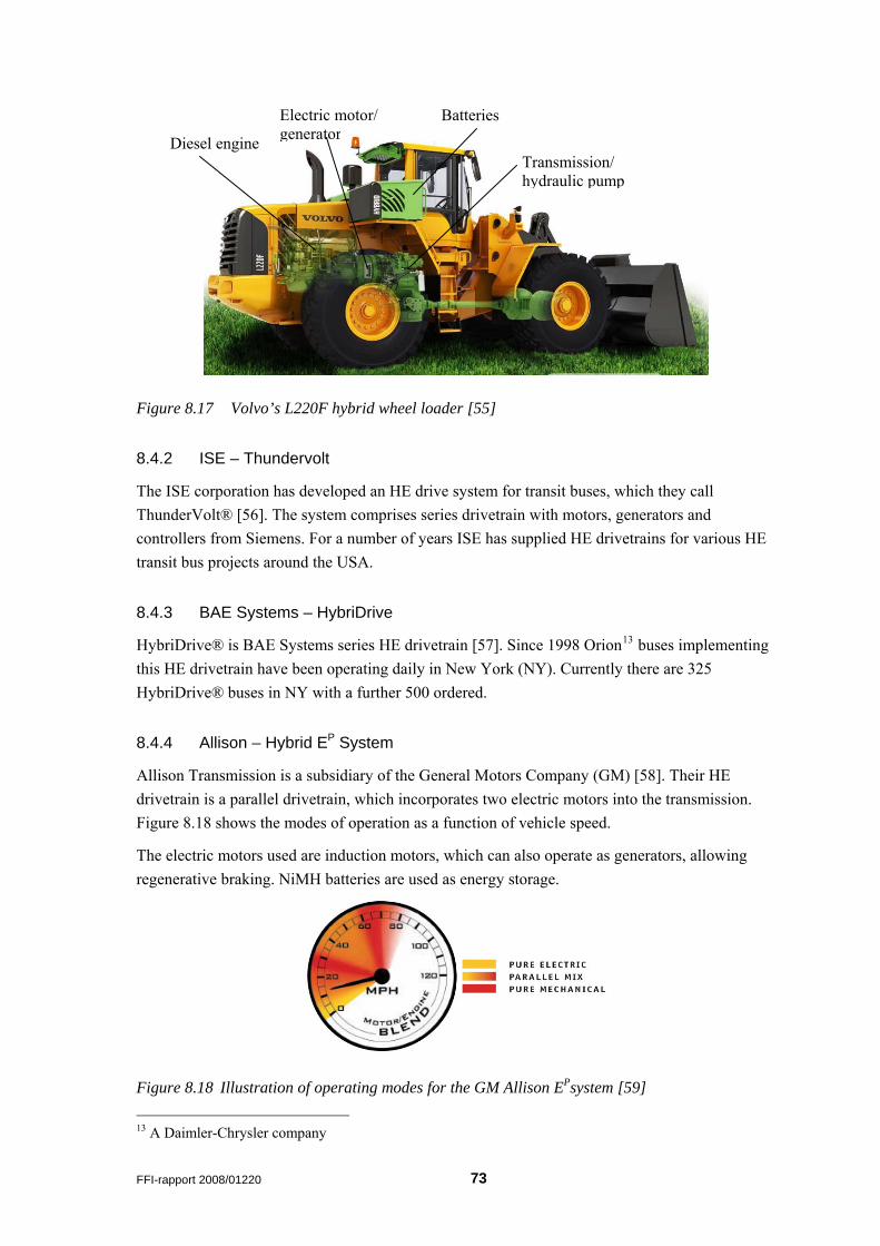
Electric motor/ generator
Batteries
Diesel engine Transmission/ hydraulic pump
Figure 8.17 Volvo’s L220F hybrid wheel loader [55]
8.4.2 ISE – Thundervolt
The ISE corporation has developed an HE drive system for transit buses, which they call ThunderVolt® [56]. The system comprises series drivetrain with motors, generators and controllers from Siemens. For a number of years ISE has supplied HE drivetrains for various HE transit bus projects around the USA.
8.4.3 BAE Systems – HybriDrive
HybriDrive® is BAE Systems series HE drivetrain [57]. Since 1998 Orion13 buses implementing this HE drivetrain have been operating daily in New York (NY). Currently there are 325 HybriDrive® buses in NY with a further 500 ordered.
8.4.4 Allison – Hybrid EP System
Allison Transmission is a subsidiary of the General Motors Company (GM) [58]. Their HE drivetrain is a parallel drivetrain, which incorporates two electric motors into the transmission. Figure 8.18 shows the modes of operation as a function of vehicle speed.
The electric motors used are induction motors, which can also operate as generators, allowing regenerative braking. NiMH batteries are used as energy storage.
Figure 8.18 Illustration of operating modes for the GM Allison EPsystem [59] 13 A Daimler-Chrysler company
FFI-rapport 2008/01220 73
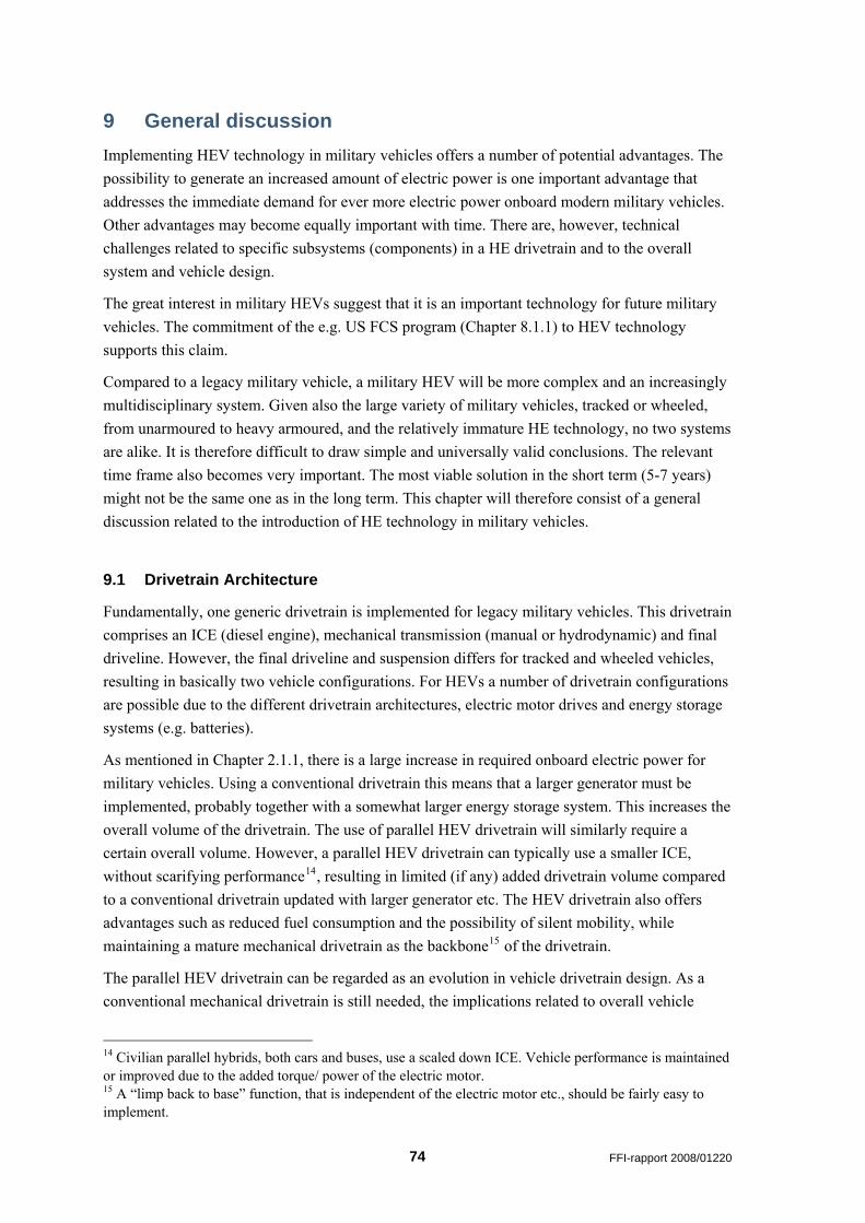
9 General discussion Implementing HEV technology in military vehicles offers a number of potential advantages. The possibility to generate an increased amount of electric power is one important advantage that addresses the immediate demand for ever more electric power onboard modern military vehicles. Other advantages may become equally important with time. There are, however, technical challenges related to specific subsystems (components) in a HE drivetrain and to the overall system and vehicle design.
The great interest in military HEVs suggest that it is an important technology for future military vehicles. The commitment of the e.g. US FCS program (Chapter 8.1.1) to HEV technology supports this claim.
Compared to a legacy military vehicle, a military HEV will be more complex and an increasingly multidisciplinary system. Given also the large variety of military vehicles, tracked or wheeled, from unarmoured to heavy armoured, and the relatively immature HE technology, no two systems are alike. It is therefore difficult to draw simple and universally valid conclusions. The relevant time frame also becomes very important. The most viable solution in the short term (5-7 years) might not be the same one as in the long term. This chapter will therefore consist of a general discussion related to the introduction of HE technology in military vehicles.
9.1 Drivetrain Architecture
Fundamentally, one generic drivetrain is implemented for legacy military vehicles. This drivetrain comprises an ICE (diesel engine), mechanical transmission (manual or hydrodynamic) and final driveline. However, the final driveline and suspension differs for tracked and wheeled vehicles, resulting in basically two vehicle configurations. For HEVs a number of drivetrain configurations are possible due to the different drivetrain architectures, electric motor drives and energy storage systems (e.g. batteries).
As mentioned in Chapter 2.1.1, there is a large increase in required onboard electric power for military vehicles. Using a conventional drivetrain this means that a larger generator must be implemented, probably together with a somewhat larger energy storage system. This increases the overall volume of the drivetrain. The use of parallel HEV drivetrain will similarly require a certain overall volume. However, a parallel HEV drivetrain can typically use a smaller ICE, without scarifying performance14, resulting in limited (if any) added drivetrain volume compared to a conventional drivetrain updated with larger generator etc. The HEV drivetrain also offers advantages such as reduced fuel consumption and the possibility of silent mobility, while maintaining a mature mechanical drivetrain as the backbone15 of the drivetrain.
The parallel HEV drivetrain can be regarded as an evolution in vehicle drivetrain design. As a conventional mechanical drivetrain is still needed, the implications related to overall vehicle
14 Civilian parallel hybrids, both cars and buses, use a scaled down ICE. Vehicle performance is maintained or improved due to the added torque/ power of the electric motor. 15 A “limp back to base” function, that is independent of the electric motor etc., should be fairly easy to implement.
74 FFI-rapport 2008/01220
design is limited. Therefore, implementing a parallel HE drivetrain, as described in e.g. Chapter 8.4.1, a wheeled multirole vehicle or heavier vehicle, such as an APC, can be designed as an HEV without departing substantially from conventional vehicle design principles. For the same reasons, existing or soon to be delivered vehicles can potentially in due time be upgraded with an HEV drivetrain. If this is practical, or economical, is however uncertain.
As shown in the overview of military HEV demonstrators in Chapter 8.3, the series drivetrain is receiving a lot of attention. The generator in a series compared to a parallel drivetrain will generally have a higher power rating, being equal to the ICE power rating. The amount of available onboard power will therefore typically be higher for a series HEV than for a parallel HEV.
The main difference between a series and parallel drivetrain is, however, that a series drivetrain does not have a complex mechanical link between ICE and wheels/ belts. As a result, a fairly extreme vehicle modularity, such as demonstrated by the Rheinmetall – Gefas (Chapter 8.3.6), is possible. New suspension configurations can also be implemented as demonstrated by the GLDS AHED 8x8 and AGMV 4x4. The AHED, for example, utilizes in-hub motors and trailing arm suspension for all wheels. This combination enables a larger internal volume, a lower overall height and also possibility of tracks on all the boogie wheel pairs. The implications of the reduced mechanical complexity are also assumed to be very important with regard to reliability, logistical footprint, life cycle cost, etc.
From a vehicle design standpoint, a series drivetrain is a more radical approach and offers some possibilities that the parallel drivetrain does not. One possibility not yet discussed is to remove the ICE altogether. Today no technology can match the characteristics of the ICE and generator combination for electric power generation for HEVs. However, in the future16 e.g. fuel cells that convert electric power directly from a fuel (diesel, kerosene, methanol, hydrogen etc.) may rival the ICE/generator combination. Such a system could then be directly implemented with a series drivetrain.
9.2 System Technologies
As shown in Table 5.1, the different electric motor configurations all have advantages and disadvantages. The electric motors can basically be implemented either as in-hub motors, axle motors or as a more centralized drive unit17. For the two latter, basically all electric motor types can be used. However, only the PM motor has been demonstrated as an in-hub motor. This is due to the high torque density required for an in-hub motor. The PM motor has, however, a major limitation in having a lower speed ratio than what is required for a military vehicle (Figure 5.3 and Figure 5.4). The PM in-hub motor could in theory implement a transmission to remedy this shortcoming, but this becomes impractical18. As a result, given the current technology, the in-hub
16 In this context the future is assumed to be 20+ years. 17 Electric motor implemented together with the ICE. Typically a parallel HE drivetrain. 18 The SEP (8.3.1) uses a two- speed reduction gearbox, but it is assumed that the vehicle must stop to shift gears. Either gradeability/ acceleration or top-speed.
FFI-rapport 2008/01220 75
motor implemented in the current military HEVs are assumed to be oversized, adding cost and reducing efficiency.
In-hub motors and electric motors used in a series drivetrain must also be designed for continuous operation, as opposed to intermittent operation in the case of a parallel drivetrain. This is assumed to effect parameters such as reliability and cost.
The state-of-the-art silicon based power electronics technology allows the desired control and functionality required for a HEV. However, emerging technologies such as SiC will greatly improve the packaging and integration of power electronics systems into the vehicle.
A key issue related to the power electronics and also the electric motors is thermal management. Due to different operating temperatures, each of these systems may require individual cooling circuits. As a result, for vehicles implementing in-hub motors, routing of the electric high voltage wires and cooling tubes to each wheel can be challenging and require a substantial volume.
The basic task of the energy storage system in an HEV is to function as an electric power buffer allowing the drivetrain to absorb short power variations. Energy storages for HEVs (batteries, ultra-capacitors, flywheel etc.) have therefore been developed with focus on specific power and cycle life. The requirements for an energy storage for silent watch and for silent mobility (electric-only propulsion) are, however, very different and are currently only partially met by batteries. A high specific energy is required, the discharge/ charge cycles are few19 and a large percentage of the batteries capacity (SOC) needs to be utilized. Achieving a single energy storage that is able to meet these very contradicting requirements and at the same time have an adequate cycle and calendar life, is very challenging.
In the case of silent watch or silent mobility, the current state-of-the-art specific energy for batteries, constitutes another challenge. As shown in Figure 2.5, the difference in specific energy between batteries and diesel (gasoline) converted using an ICE, is approximately a factor 15-5020. Therefore, the required battery weight to achieve a certain silent mobility (electric-only) range will be a factor 15-50 higher than the weight of diesel required to achieve the same range, using a conventional drivetrain. In the evaluation of SEP, FMV concluded that the added weight and volume of batteries to achieve silent mobility, was hard to justify (Chapter 8.3.1). As a result, the SEP demonstrators have mostly been operated as diesel-electric and not as true HEV.
9.3 Civilian Technology
In [50] (Chapter 8.3.9) it is suggested that civilian HEV technology, developed for a much larger market than the military market, should be utilized in military HEVs to reduce development time, cost etc. Currently there are about 20 passenger HEVs commercially available, while HE heavy vehicles are maturing with some HE buses being more or less commercially available. With
19 Compared to a typical HEV energy storage, the number of cycles is orders of magnitude lower. 20 ICE assumed to have an efficiency of 5-30%, whereas the efficiency of the electric drive (battery discharge, DC conversion, electric motor etc.) is assumed to be 80%. The specific energy of diesel is 11700 Wh/kg whereas the specifc energy of Lit-Ion batteries is ~140 Wh/kg.
76 FFI-rapport 2008/01220
regard to military vehicles, the technology for HE heavy vehicles is most interesting. However, there are numerous technologies that cross the weight categories.
As mentioned above, a parallel drivetrain developed for a civilian HE truck (Chapter 8.4.1) for instance, should be possible to implement in a military vehicle without departing substantially from legacy vehicle design principles. A truck drivetrain will also be developed for a variety of operating modes, many of which are shared with a military vehicle.
Civilian heavy vehicles that implement a series drivetrain have to date been either city buses or other specialized vehicles. There are, however, substantial differences between a city bus and a military vehicle with respect to both operating mode and design. The current HE buses operate with regular starts and stops in large cities that are relatively flat. The operating mode is therefore relatively simple, and the HE bus can be optimised accordingly. For a city bus a fairly large volume can be made available for the drivetrain, which also only needs to deliver power to one axle. The technology transfer between civilian HE heavy vehicles and military vehicles is thus assumed to be more challenging for a series drivetrain than for a parallel drivetrain.
9.4 Cost
According to [19], the initial cost of military HEVs will be higher than for a conventional vehicle. However, it is argued that the life cycle cost (LCC) will be lower. One argument used, which is independent of drivetrain architecture, is that the vehicle will implement more and better diagnostics, increasing the service efficiency.
Modular vehicles with a series drivetrain offer additional advantages, such as, high degree of part commonality21. Due to the limited number of bulky mechanical drivetrain components, the logistical burden should also be reduced. The technological maturity of critical components is, however, still fairly low and based on limited field testing. There are therefore large uncertainties related to the LCC. Another implication of HEV technology is that service personnel must be trained in a new technology.
21 E.g. the GDLS AHED (8.3.2) utilizes the same suspension components and electric motors for all eight wheels.
FFI-rapport 2008/01220 77
10 Concluding Remarks The intention of this report has been to give an overview of the HEV technology for military vehicles. Key technologies and design principles have been presented, some in more detail then others. The different programs and efforts related to the development of military HEVs have also presented.
The status of the technology depends on vehicle type (role, weight, tracked or wheeled etc.) and the drivetrain architecture opted for. However, some concluding remarks can be made with regard to time of fielding, type of vehicle, advantages and challenges, etc.
It is the author’s opinion, that the first military HEV will be fielded in approximately 5-7 years and will be a wheeled multirole vehicle, weighing 5.000-10.000kg, implementing a parallel drivetrain. This claim is based on the maturity of the technology and the planned completion of the US JLTV program (Chapter 8.1.2) in 2012. However, an important assumption is that an HEV demonstrator is indeed selected in June 2008 for participation in the JLTV demonstration phase.
Civilian HE trucks with a parallel drivetrain will soon be commercially available (Chapter 8.4.1). Due to the similarities in drivetrain, it is assumed that, for example, armoured personnel carriers (APC) (Figure 3.7) implementing a parallel drivetrain may also be fielded in approximately 5-7 years. Currently there is, however, no known activity on an APC with a parallel drivetrain.
The two vehicle concepts described above will have features, such as increased onboard electric power and capacity, reduced fuel consumption and the potential for a short range silent mobility capacity.
The series drivetrain is a technology for the future (7-10+ years). However, the commitment of the US FCS program (Chapter 8.1.1) is a strong indicator of the potential of the technology. Two tracked chassis, both weighing approximately 20.000 kg, will be developed and configured for different roles and replace a wide range of vehicles22. The Swedish SEP program has developed a demonstrator based on a similar concept, but is somewhat lighter. The FCS program, set to be completed in 2014, will also be an important HEV technology driver.
Numerous wheeled 6x6 and 8x8 HEVs with a series drivetrain and in-hub motors have also been demonstrated, e.g. the SEP (Chapter 8.3.1) and AHED (Chapter 8.3.2). The initial plans for these vehicles were very ambitious, with BAE Hägglunds planning fielding already in 2011. Given the current status of the SEP program (Chapter 8.1.4), the immaturity of key technologies and the lack of standards (STANAGs etc.), this will be a far reach indeed.
Currently, neither the SEP nor the AHED are contenders for the FRES program (Chapter 8.1.3) or other similar vehicle development/ procurement programs. It is therefore difficult to predic when a heavy (10.000-20.000 kg) wheeled military HEV will be fielded.
22 It is also proposed that some of these configurations will even replace heavily armored vehicles such as the main battle tank.
78 FFI-rapport 2008/01220

The potential of the series drivetrain technology is very good, enabling features such as increased in onboard electric power and capacity, reduced fuel consumption, flexibility in vehicle design, reduced mechanical complexity and the potential for a silent mobility capacity23. The mobility of wheeled vehicles will also be improved due to better torque control on each wheel. The reduced mechanical complexity will potentially improve reliability, improve survivability, reduce the logistical footprint and reduce the LCC.
As mentioned earlier, if or not HEVs are selected as contenders for the JLTV and FRES program, will be important indicators on the maturity of the technology and actual operational value of the enabled features, seen from a military point of view. These selections will also have a strong influence on when military HEVs will be fielded.
The way war is fought is rapidly changing, and terms such as Three (or Four) Block War and Asymmetric Warfare are frequently used. As a result, vehicle requirements have just over the last couple of years changed considerably, and will also likely continue to change. Given the key features and advantages enabled by HEV technology, it is the author’s opinion, that HEV technology will be important in meeting the changing vehicle requirements.
23 Very dependant on the development of batteries or other energy storage systems with a high specific energy (Wh/kg).
FFI-rapport 2008/01220 79
References [1] "Fuel Efficiency: How it works," in www.hybridsynergydrive.com 2008.
[2] Grace M.Bochenek and Jennifer Hitchcock, "Army Transitions Hybrid Electric Technology to FCS Manned Ground Vehicles," in Army AL&T 2007.
[3] Hathan Hodge, "Interview: Dr Thomas Killion, US Army Chief Scientist, Deputy Assistant Secretary for Research and Technology," in Jane's International Defence Review 2007.
[4] RTO Applied Vehicle Technology Panel (AVT), "All Electric Combat Vehicles (AECV) for Future Applications," NATO RTO,TR-AVT-047, June2004.
[5] Ken Winters, "Enhancing the Brigade Combat Team: Battlefield Power to Meet Today's and Tomorrow's Needs," 2007.
[6] Ehsani et al., Modern Electric, Hybrid Electric, and Fuel Cell Vehicles - Fundamentals, Theory, and Design CRC Press, 2005.
[7] Maj.Allen, "Hybrid Electric Vehicle Experimentation and Assessment,"Report number: 17522, Aug.2007.
[8] Jack Taylor, "Army's energy needs," 2007.
[9] R.M.Ogorkiewicz, "Novel electric vehicle offered for the US JLTV requirement," in Jane's International Defence Review 2007.
[10] M.Ehsani and et al., "Hybrid Electric Vehicles: Architecture and Motor Drives," Proceedings of the IEEE, vol. 95, no. 4 2007.
[11] B.Bernhard, "Electric power transmission for a modular Advanced Vehicle System," 2007.
[12] C.C.Chan, "Guest Editorial: Scanning the Issue," Proceedings of the IEEE, vol. 95, no. 4 2007.
[13] C.C.Chan, "The State of the Art of Electric, Hybrid, and Fuel Cell Vehicles," Proceedings of the IEEE, vol. 95, no. 4 2007.
[14] Z.John Shen and Ichiro Omura, "Power Semiconductor Devices for Hybrid, Electric, and Fuel Cell Vehicles," Proceedings of the IEEE, vol. 95, no. 4 2007.
[15] Hærens Forsyningskommando, "Transparantserie CV9030 N for Kavaleriet, Skrog tekniker," 1998.
[16] R.Pengelley, "FRES gets reality check from the "asymmetric" battlefield," in Jane's International Defence Review 2007.
[17] R.Pengelley, "FRES gets reality check from the "asymmetric" battlefield," in Jane's International Defence Review 2007.
80 FFI-rapport 2008/01220
[18] Hærens Forsyningskommando, "Transparantserie CV9030 N for Kavaleriet, Skrog
bruker," 1998.
[19] Mark Stephens, "The Advanced Hybrid Electric Drive 8x8 Trails: Demonstrated reliability growth in medium E-Drive vehicles," 2007.
[20] R.M.Ogorkiewicz, "Novel electric vehicle offered for the US JLTV requirement," in Jane's International Defence Review 2007.
[21] P.Mongeau, "Advanced Traction Motor Technology Development," 2007.
[22] Yimin Gao and Mehrdad Ehsani, "Parametric Design of the Traction Motor and Energy Storage for Series Hybrid Off-Road and Military Vehicles," IEEE Transactions on Power ELectronics, vol. 21, no. 3 2006.
[23] "Combat Hybrid Power System Components Technologies - Technical Challenges and Research Priorites," The National Academies Press,2002.
[24] Peter Erhart, "Electric Drive and Energy Supply Systems for Military Vehicles," 2007.
[25] Andrew F.Burke, "Batteries and Ultracapacitors for Electric, Hybrid, and Fuel Cell Vehicles," Proceedings of the IEEE, vol. 95, no. 4, pp. 806-820, 2007.
[26] "Combat Hybrid Power System Components Technologies - Technical Challenges and Research Priorites," The National Academies Press,2002.
[27] "Magnetodynamic Storage (MDS)," in www.magnet-motor.com/ 2008.
[28] "Magnetodynamic Storage (MDS)," in www.magnet-motor.com/ 2008.
[29] Eric H Biass and Ian Kemp, "Future Combat Systems," in Armada International 2006.
[30] "Future Combat System," in www.wikipedia.org 2008.
[31] Scott R.Gourley, "US DoD issues RfP for JLTV TD phase," in Jane's International Defence Review 2008.
[32] R.Pengelley, "FRES gets reality check from the "asymmetric" battlefield," in Jane's International Defence Review 2007.
[33] R.Pengelley, "FRES gets reality check from the "asymmetric" battlefield," in Jane's International Defence Review 2007.
[34] Rickard O.Lindström, "SEP - On the way to series production," 2007.
[35] "Combat Hybrid Power System Components Technologies - Technical Challenges and Research Priorites," The National Academies Press,2002.
[36] RTO Applied Vehicle Technology Panel (AVT), "All Electric Combat Vehicles (AECV) for Future Applications," NATO RTO,TR-AVT-047, June2004.
[37] RTO Applied Vehicle Technology Panel (AVT), "Hybrid Vehicle Rating Criteria," RTO Applied Vehicle Technology Panel (AVT),RTO-TR-AVT-106, 2008.
[38] Maj.Allen, "Hybrid Electric Vehicle Experimentation and Assessment,"Report number: 17522, Aug.2007.
FFI-rapport 2008/01220 81
[39] "SEP Modular Armoured Tectical System Wheeled and Tracked Vehicles, Sweden," in
www.army-technology.com 2007.
[40] Per Boeryd, "Expectations, realization and conclusions of electric drive system based on FMV technology demonstrators," 2007.
[41] "Military Applications of Hybrid Cars and Trucks," in www.defense-update.com 2005.
[42] Jeff Humble, "Hybrid Electric Drive Applications In Tactical Vehicles: The GDLS Joint Ligth Tactical Vehicle (JLTV) Technology Feeder," 2007.
[43] Ted Latiak, "The Army Goes Green," in Popular Mechanics 2006.
[44] "Northrop Grumman, Oshkosh JLTV Features Leapfrog Diesel-Electric Drive Design," in www.northropgrumman.com 2008.
[45] "ProPulse - Hybrid Electric Drive Technology," in www.oshkoshdefense.com/ 2008.
[46] Wolfgang Petermann, "JLTV Information Briefing to Industry," 2008.
[47] "Light Utility Vehicle," in www.millenworks.com 2008.
[48] Arne Lind, "Semi-active suspension systems using magneto-rheological fluids,"FFI-rapport 2008/00895, Apr.2008.
[49] "Light Utility Vehicle," in www.millenworks.com 2008.
[50] Raphael Moreno, "Serial Hybrid Electric Military Demonstrator," 2007.
[51] "The Volvo FM Hybrid Concept," in www.volvo.com/trucks 2008.
[52] "The Volvo FM Hybrid Concept," in www.volvo.com/trucks 2008.
[53] "L220F Hybrid - Volvo wheel loader," in www.volvo.com/constructionequipment/na/en-us/products/Innovations/hybrids/ 2008.
[54] "Hybrys," in www.renault-trucks.com 2008.
[55] "L220F Hybrid - Volvo wheel loader," in www.volvo.com/constructionequipment/na/en-us/products/Innovations/hybrids/ 2008.
[56] "THUNDERVOLT Hybrid Drive Systems," in www.isecorp.com/ 2008.
[57] "HybriDrive Propulsion System," in www.baesystems.com 2008.
[58] "EP System," in www.allisontransmission.com 2008.
[59] "EP System," in www.allisontransmission.com 2008.
82 FFI-rapport 2008/01220
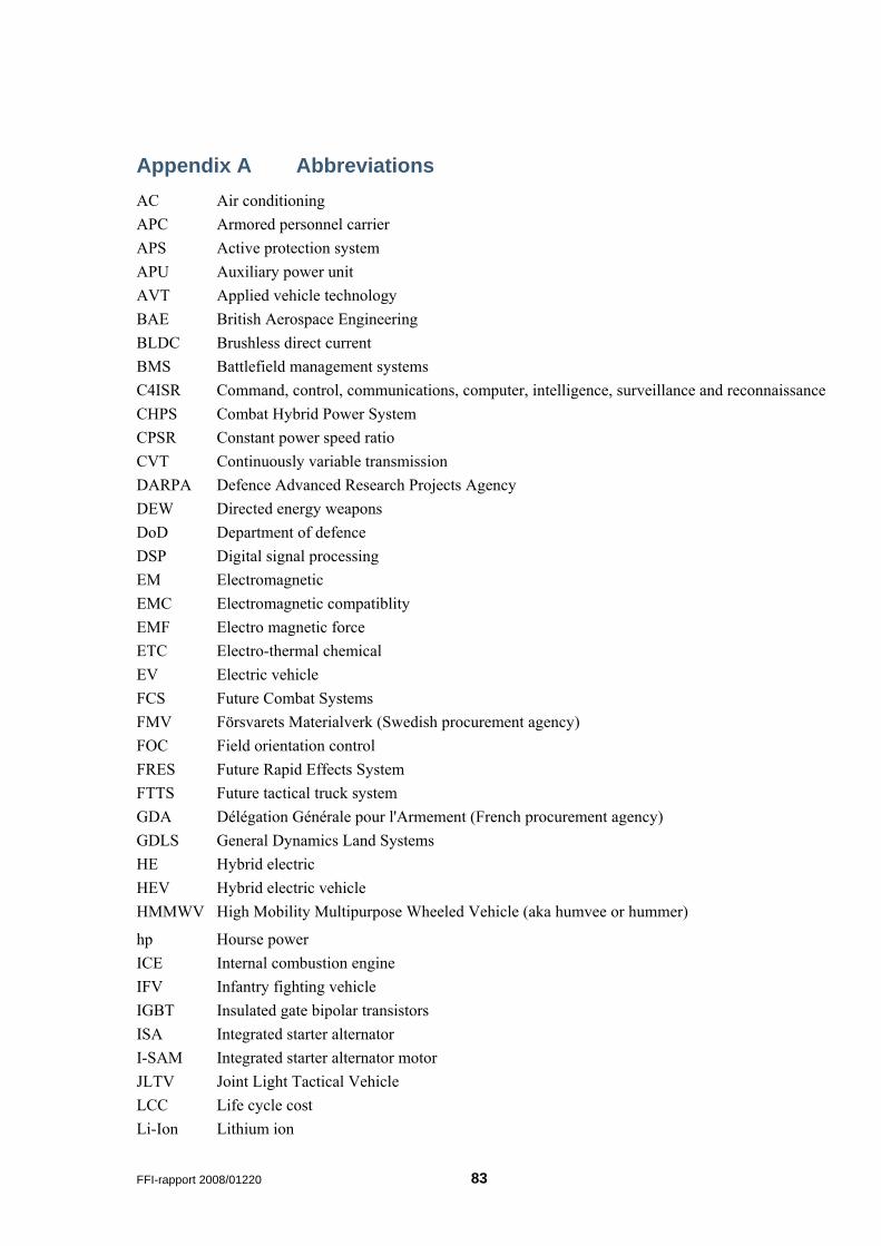
Appendix A Abbreviations AC Air conditioning APC Armored personnel carrier APS Active protection system APU Auxiliary power unit AVT Applied vehicle technology BAE British Aerospace Engineering BLDC Brushless direct current BMS Battlefield management systems C4ISR Command, control, communications, computer, intelligence, surveillance and reconnaissanceCHPS Combat Hybrid Power System CPSR Constant power speed ratio CVT Continuously variable transmission DARPA Defence Advanced Research Projects Agency DEW Directed energy weapons DoD Department of defence DSP Digital signal processing EM Electromagnetic EMC Electromagnetic compatiblity EMF Electro magnetic force ETC Electro-thermal chemical EV Electric vehicle FCS Future Combat Systems FMV Försvarets Materialverk (Swedish procurement agency) FOC Field orientation control FRES Future Rapid Effects System FTTS Future tactical truck system GDA Délégation Générale pour l'Armement (French procurement agency) GDLS General Dynamics Land Systems HE Hybrid electric HEV Hybrid electric vehicle HMMWV High Mobility Multipurpose Wheeled Vehicle (aka humvee or hummer)
hp Hourse power ICE Internal combustion engine IFV Infantry fighting vehicle IGBT Insulated gate bipolar transistors ISA Integrated starter alternator I-SAM Integrated starter alternator motor JLTV Joint Light Tactical Vehicle LCC Life cycle cost Li-Ion Lithium ion
FFI-rapport 2008/01220 83
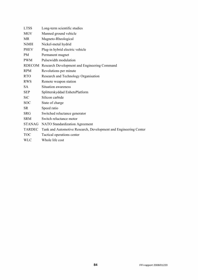
LTSS Long-term scientific studies MGV Manned ground vehicle MR Magneto-Rheological NiMH Nickel-metal hydrid PHEV Plug-in hybrid electric vehicle PM Permanent magnet PWM Pulsewidth modulation RDECOM Research Development and Engineering Command RPM Revolutions per minute RTO Research and Technology Organisation RWS Remote weapon station SA Situation awareness SEP Splitterskyddad EnhetsPlatform SiC Silicon carbide SOC State of charge SR Speed ratio SRG Switched reluctance generator SRM Switch reluctance motor STANAG NATO Standardization Agreement TARDEC Tank and Automotive Research, Development and Engineering Center TOC Tactical operations center WLC Whole life cost
84 FFI-rapport 2008/01220