hybrid electric & hydraulic drives - diva portal444188/fulltext01.pdf · objective of...
TRANSCRIPT

HYBRID ELECTRIC & HYDRAULIC DRIVES
Mohammadreza Sadeghi
Ali Mohammed Fahimi Rezaii
Fluid and Mechatronic Systems
Degree Project
Department of Management and Engineering
LIU-IEI-TEK-A--10/00977--SE

2 Hybrid Electric & Hydraulic Drives
ABSTRACT
The environmental impact of fossil fuel consumption has been a significant issue over the last
decade. Mainly because of public awareness, increased fuel cost and stricter legislation.
Today’s technological improvements have reduced fuel consumption and also emission of
vehicles considerably. One of the most important solutions to this problem is hybridization.
Hybridization in vehicle is using two or more distinct power sources. Additionally, the main
objective of hybridization in vehicle is improving the fuel consumption and reducing
hazardous air pollutants without lowering vehicle performance and other satisfaction criteria.
Development of hybridization systems can be fallen into two categories: electric and
hydraulic hybrids.
This project illustrates performances of HHV (hybrid hydraulic vehicles) and HEV (hybrid
electric vehicles) in NEDC (New European Driving Cycle) and 10-15 mode (Japanese
Driving cycle) by using simulation models, which has been done by the LMS Imagine Lab
Amesim rev 7th
and 8th
.
The following paper compares HRB (hydraulic regenerative braking system) as a hydraulic
system and a parallel hybrid electric system (HEV) with the Nickel-metal hydride (NiMH)
battery on the light weight vehicle (1 ton). Results show higher performance in HEV, about
13.7% during NEDC and 25.4% during (10-15) improvement in fuel consumption although
high energy density and low power density are inherent battery characteristics. Also, all the
evidence point to high cost components and short- life time.
The HRB model saves around 11% during NEDC and 23.3% during 10-15Mode in fuel
consumption in addition to high power density and low energy density .In other words,
limitation for accumulating energy is an intrinsic system character. However, high response,
low component cost and weight with long life time are advantages of HRB.
Two problems exiting in HRB model are: firstly, the necessity of using big size pumps for
fully charging hydraulic accumulators that would be impossible in a light vehicle; and
secondly the limitation of capturing huge amount of energy in accumulators. In this paper the
attempt is made to explicate some of the brand new solutions to alleviate some of these weak
points.

3 Hybrid Electric & Hydraulic Drives
INDEX
ABSTRACT .......................................................................................................................... 2
INDEX .................................................................................................................................. 3
Figures: .................................................................................................................................. 4
Tables: ................................................................................................................................... 5
1. Introduction: ......................................................................................................................... 6
1.1 The first hybrid vehicle: ....................................................................................................... 6
1.2 Hybrid vehicle God father: ................................................................................................... 7
1.3 New hybrid technologies: ..................................................................................................... 9
1.4 Hybrid Electric Series systems ........................................................................................... 10
1.5 Hybrid Electric parallel systems ........................................................................................ 11
1.6 Split parallel Hybrid ........................................................................................................... 12
1.7 Combined Series and parallel system (Toyota Prius) ........................................................ 13
1.8 HRB-Hydrostatic/Hydraulic regenerative braking system ................................................ 18
1.9 Digital displacement hydraulic hybrid: .............................................................................. 19
2 Simulations .......................................................................................................................... 20
2.1 NEDC (New European Driving Cycle): ............................................................................. 21
2.2 Japanese 10-15 mode-driving cycle: .................................................................................. 22
2.3 Basic Gasoline vehicle with a manual Gearbox: ................................................................ 22
2.4 Parallel Hybrid Electric Vehicle: ....................................................................................... 24
2.5 Hybrid Electric Vehicle (HEV) Results: ............................................................................ 31
2.6 Battery state of charge: ....................................................................................................... 32
2.7 Comparing Basic and HEV (Hybrid Electric vehicles): .................................................... 32
3. Hybrid Hydraulic Vehicle (HHV) ...................................................................................... 33
3.1 Hydraulic Regenerative Braking System (HRB) ............................................................... 33
3.2 Design a controller for HRB by Amesim: .......................................................................... 34
3.3 Pump controller: ................................................................................................................. 34
3.4 Motor / Accumulator controller: ........................................................................................ 35
3.5 Pressure relief controller: ................................................................................................... 35
3.6 Clutch controller: ................................................................................................................ 35
3.7 Fully Charged Hydraulic Accumulator (HA001): ............................................................. 35
3.8 Adjusting controller gains: ................................................................................................. 35
3.9 Pump Parameters: ............................................................................................................... 37
4. Calculate HRB fuel efficiency improvement: .................................................................... 38
4.1 Theoretical Methods to estimate fuel efficiency improvement in HRB ............................ 38
4.2 Comparing torque diagrams: .............................................................................................. 40
4.3 Theoretical results of fuel improvement in HRB system: .................................................. 41
5. New Idea: ........................................................................................................................... 48
5.1 Waste Heat Recovery Schematic for Regenerative Braking System ................................. 48
5.2 Modification of Waste Heat Recovery Schematic for Regenerative Braking System. ...... 50
5.3 Preheat Volume: ................................................................................................................. 50
Conclusions: ............................................................................................................................. 52
Appendix 1: Basic Model Parameters of components ............................................................. 53
Appendix 2: parameters of HRB components .......................................................................... 56
Appendix 3: Parameters of HEV components: ........................................................................ 58
4 Hybrid Electric & Hydraulic Drives
Figures: Figure: 1 Henri Pieper's 1905 Hybrid Vehicle Patent Application. [14] ................................................................. 6
Figure: 2 Ferdinand Porsche has invented the first 4x4 or 4 wheel drive Hybrid vehicle. [13] .............................. 7
Figure: 3 Victor Wouk was a pioneer for electric and hybrid vehicle development. [16] ...................................... 8
Figure: 4 A detailed electrical circuit diagram. Wouk’s data are in the lower right corner. [16] ............................ 8
Figure: 5 HEV (Hybrid electric series vehicle) [17] ............................................................................................. 10
Figure: 6 HEV (Parallel hybrid electric vehicle) [17] ........................................................................................... 11
Figure: 7 Power split parallel hybrid system [17] ................................................................................................. 12
Figure: 8 combination of series and parallel systems [17] .................................................................................... 13
Figure: 9 drive train component in Toyota prius [12] ........................................................................................... 14
Figure: 10:LCD in prius toyota. ............................................................................................................................ 15
Figure: 11 Nickel-metal hydride (NiMH) battery of Toyota Prius. [18] ............................................................... 16
Figure: 12 inverter unit in hybrid prius Toyota. [12] ............................................................................................ 16
Figure: 13 Power split mechanism (Planetary Gear) [12] ..................................................................................... 17
Figure: 14 Illustrate braking frequency and power in different machines [2] ....................................................... 18
Figure: 15 Standard Bosch components for HRB, [2] .......................................................................................... 19
Figure: 16 Digital displacement pump/motor controlled by a computer. [2] ........................................................ 19
Figure: 17 Artemis technology is installed on BMW 530i [2] ............................... Error! Bookmark not defined.
Figure: 18 NEDC (New European Driving Cycle) to assess the emission levels of car engine [5] ...................... 21
Figure: 19 Japanese 10-15 mode mission driving cycle. [5] ................................................................................. 22
Figure: 20 Basic Model of Gasoline vehicle with manual Gearbox simulated in Amesim ................................... 23
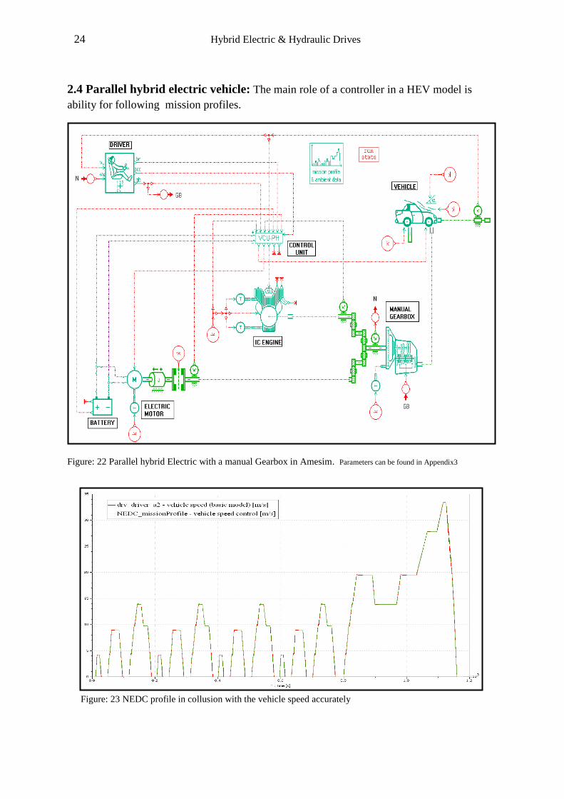
Figure: 21 Gearbox ratio control (Basic Model) During NEDC ........................................................................... 23
Figure: 22 Parallel hybrid Electric with a manual Gearbox in Amesim ............................................................... 24
Figure: 23 NEDC profile in collusion with the vehicle speed accurately ............................................................. 24
Figure: 24 Total fuel consumption for Basic and HEV models during NEDC (depth of discharge=40%)........... 25
Figure: 25 Discrepancy in Total fuel consumption in Basic and HEV-NEDC (discharge depth 25%) ................ 26
Figure: 26 Operating mode (electric/hybrid) in HEV model during NEDC (discharge depth 25%). ................... 26
Figure: 27 Discrepancy in total fuel consumption during (10-15) in HEV (discharge depth 25%). ..................... 27
Figure: 28 Operating mode in HEV model during Japanese driving cycle (10-15) (discharge depth 25%) ........ 27
Figure: 29 fuel efficiency improvement. Operating mode in HEV (10-15) (discharge depth 40%) ..................... 28
Figure: 30 Co emissions in HEVand Basic models during NEDC and operating modes (discharge depth 25%) 29
Figure: 31 Exhaust gas flow rate in HEVand Basic models during NEDC (discharge depth 25%) ..................... 30
Figure: 32 Battery state of discharge during NEDC in HEV model (discharge state 25% and 40%). .................. 31
Figure: 33 Pump shaft speed diagram in HHV during NEDC (maximum=1955.93rpm). .................................... 33
Figure: 34 Four controller parts: pump, pressure relief, clutch and motor/accumulator. ...................................... 34
Figure: 35 Collusion of mission profile and vehicle speed in NEDC for capturing maximum kinetic energy ..... 36
Figure: 36 effect of releasing potential energy in an acceleration time(117s)...................................................... 38
Figure: 37 shows charging and discharging Accumulator positions in (0-206seconds). ...................................... 39
Figure: 38 Engine and pump torque diagrams during NEDC. .............................................................................. 39
Figure: 39 two torque sensors and omegacon Sub model to convert signal to angle in degree ............................ 40
Figure: 40 similar system for estimation torques that’s save as hydraulic energy in an accumulator. .................. 40
Figure: 41 Hydraulic regenerative braking system retrofit in a basic model with a manual gearbox. .................. 42
Figure: 42 behavior of HRB system during 10-15cycle. ....................................................................................... 43
Figure: 43 behavior of HRB system during NEDC cycle. .................................................................................... 43
Figure: 44 HEV analysis ....................................................................................................................................... 44
Figure: 45 HHV analysis. ...................................................................................................................................... 45
Figure: 46 Conceptual Schematic of waste Heat Recovery System for HRB-Regenerative braking system........ 48
Figure: 47 Using an injector and an electric control unite (ECU) in a waste heat recovery system ..................... 49
5 Hybrid Electric & Hydraulic Drives
Figure: 48 Modification of Waste Heat Recovery in HRB ................................................................................... 50
Figure: 49 Uncompleted simulation of waste heat recovery of regenerative braking system by Amesim rev 8th
. 51
Tables:
Table1-1:NiMH (ZVW30) Battery specifications[18] ............................................................. 16
Table2-1: Summary of ECE and EUDC cycles in NEDC [5] .................................................. 21
Table 2-2: Summary of Japanese 10-15 emission driving cycle [5] ........................................ 22
Table 2-3:HEV(Hybrid electric vehicle) RESULTS ............................................................... 31
Table 3-1: Parameters of HRB during NEDC/10-15[2] ........................................................... 37
Table 4-1:Theoretical results of fuel improvement in HRB system ........................................ 41
Table 4-2: Comparing HHV and HEV characteristics. ............................................................ 46

6 Hybrid Electric & Hydraulic Drives
1. Introduction:
1.1 The first hybrid vehicle:
March 2nd 2009 was the 100th anniversary of the first US hybrid car patent that was called the “Mixed drive for
Autovehivles”.
Figure: 1 Henri Pieper's 1905 Hybrid Vehicle Patent Application. [14]
Henri Pieper, a German-born who was an inventor and a gun maker from Belgium on
November 23rd, 1905 submitted his application and was granted a US patent in 1909.In
opening paragraph he says:
“Be it known that I, Henri Pieper, a subject of the King of Belgium, residing at 18 Rue des
Bayard’s, in Liege, Belgium, have invented new and useful Improvements in Mixed Drives for
Auto vehicles…The invention…comprises an internal combustion or similar engine, a dynamo
motor direct connected therewith, and a storage battery or accumulator in circuit with the
dynamo motor, these elements being cooperatively related so that the dynamo motor may be
run as a motor by the electrical energy stored in the accumulator to start the engine or to
furnish a portion of the power delivered by the set, or may be run as a generator by the
engine, when the power of the latter is in excess of that demanded of the set, and caused to
store energy in the accumulator.”
7 Hybrid Electric & Hydraulic Drives
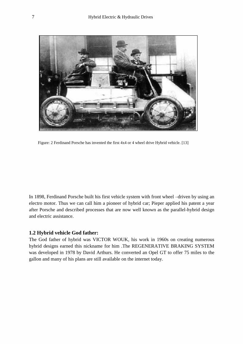
In 1898, Ferdinand Porsche built his first vehicle system with front wheel –driven by using an
electro motor. Thus we can call him a pioneer of hybrid car; Pieper applied his patent a year
after Porsche and described processes that are now well known as the parallel-hybrid design
and electric assistance.
1.2 Hybrid vehicle God father:
The God father of hybrid was VICTOR WOUK, his work in 1960s on creating numerous
hybrid designs earned this nickname for him .The REGENERATIVE BRAKING SYSTEM
was developed in 1978 by David Arthurs. He converted an Opel GT to offer 75 miles to the
gallon and many of his plans are still available on the internet today.
Figure: 2 Ferdinand Porsche has invented the first 4x4 or 4 wheel drive Hybrid vehicle. [13]
8 Hybrid Electric & Hydraulic Drives
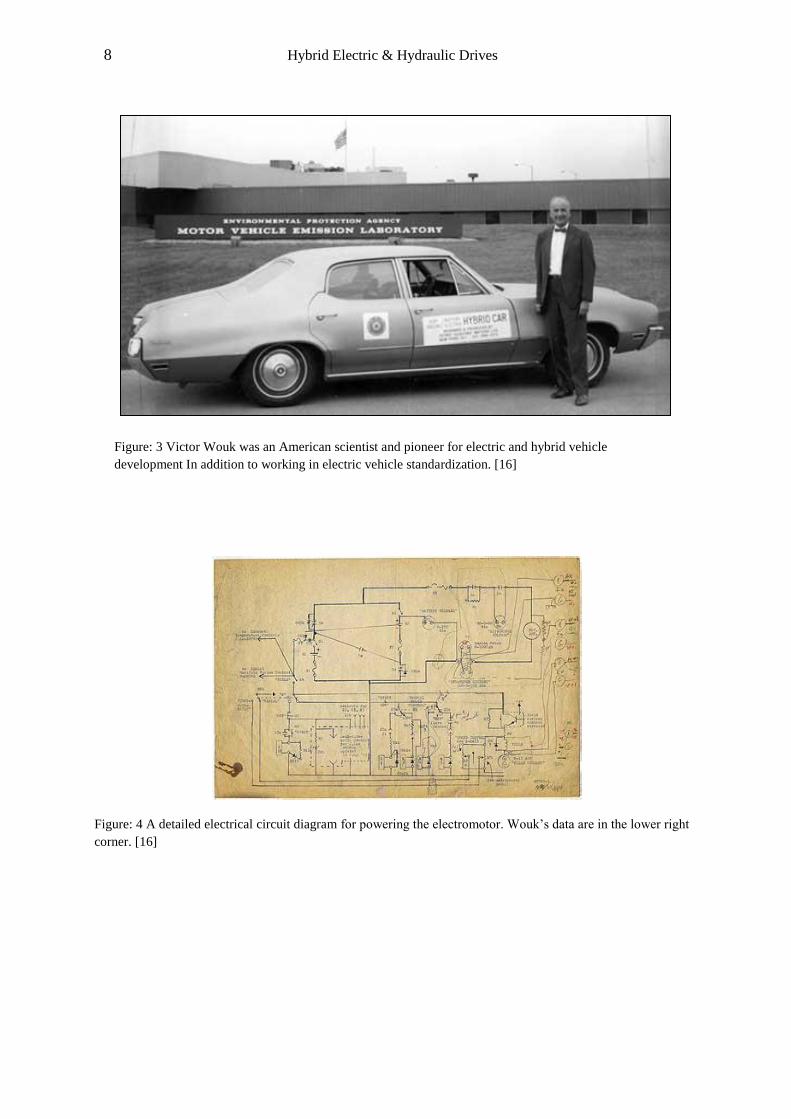
Figure: 4 A detailed electrical circuit diagram for powering the electromotor. Wouk’s data are in the lower right
corner. [16]
Figure: 3 Victor Wouk was an American scientist and pioneer for electric and hybrid vehicle
development In addition to working in electric vehicle standardization. [16]
9 Hybrid Electric & Hydraulic Drives
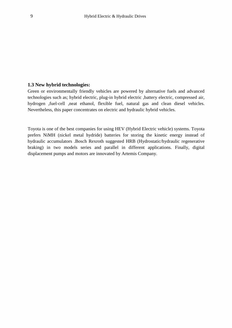
1.3 New hybrid technologies:
Green or environmentally friendly vehicles are powered by alternative fuels and advanced
technologies such as; hybrid electric, plug-in hybrid electric ,battery electric, compressed air,
hydrogen ,fuel-cell ,neat ethanol, flexible fuel, natural gas and clean diesel vehicles.
Nevertheless, this paper concentrates on electric and hydraulic hybrid vehicles.
Toyota is one of the best companies for using HEV (Hybrid Electric vehicle) systems. Toyota
prefers NiMH (nickel metal hydride) batteries for storing the kinetic energy instead of
hydraulic accumulators .Bosch Rexroth suggested HRB (Hydrostatic/hydraulic regenerative
braking) in two models series and parallel in different applications. Finally, digital
displacement pumps and motors are innovated by Artemis Company.
10 Hybrid Electric & Hydraulic Drives
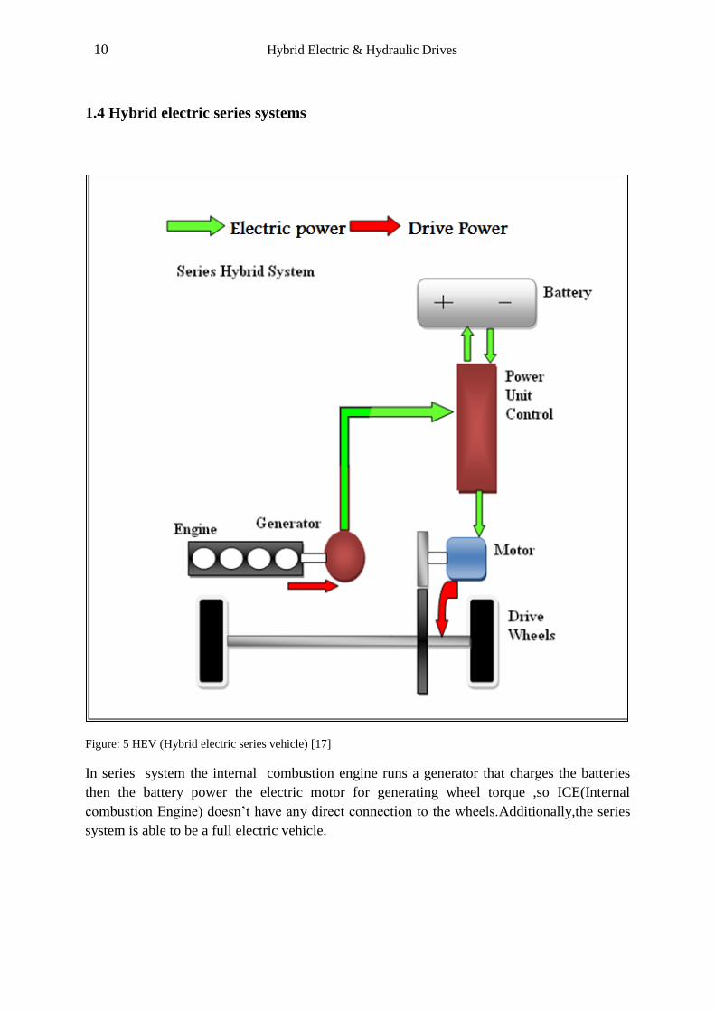
1.4 Hybrid electric series systems
Figure: 5 HEV (Hybrid electric series vehicle) [17]
In series system the internal combustion engine runs a generator that charges the batteries
then the battery power the electric motor for generating wheel torque ,so ICE(Internal
combustion Engine) doesn’t have any direct connection to the wheels.Additionally,the series
system is able to be a full electric vehicle.
11 Hybrid Electric & Hydraulic Drives
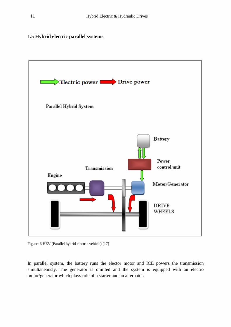
1.5 Hybrid electric parallel systems
Figure: 6 HEV (Parallel hybrid electric vehicle) [17]
In parallel system, the battery runs the elector motor and ICE powers the transmission
simultaneously. The generator is omitted and the system is equipped with an electro
motor/generator which plays role of a starter and an alternator.
12 Hybrid Electric & Hydraulic Drives
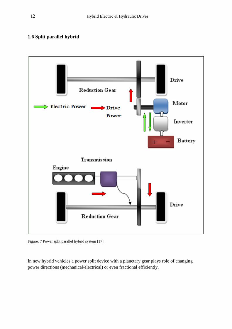
1.6 Split parallel hybrid
Figure: 7 Power split parallel hybrid system [17]
In new hybrid vehicles a power split device with a planetary gear plays role of changing
power directions (mechanical/electrical) or even fractional efficiently.

13 Hybrid Electric & Hydraulic Drives
1.7 Combined series and parallel system (Toyota Prius)
Figure: 8 combination of series and parallel systems [17]
The combined series –parallel systems can work as a series and parallel or fractional systems.
Prius can use the batteries energy for urban roads with low pollutant and ICE (Internal
combustion engine) in highway with high speed. Additionally, it can use both power sources
at acceleration time.
Toyota Prius is the best seller full hybrid electric mid- size car in the United States. According
to the United States Environmental Protection Agency is the most fuel efficient gasoline car.
Moreover, California Air Resources Board (CARB) has chosen it as the cleanest vehicle sold
in the United States. Thus, technological review on this model is valuable.
14 Hybrid Electric & Hydraulic Drives
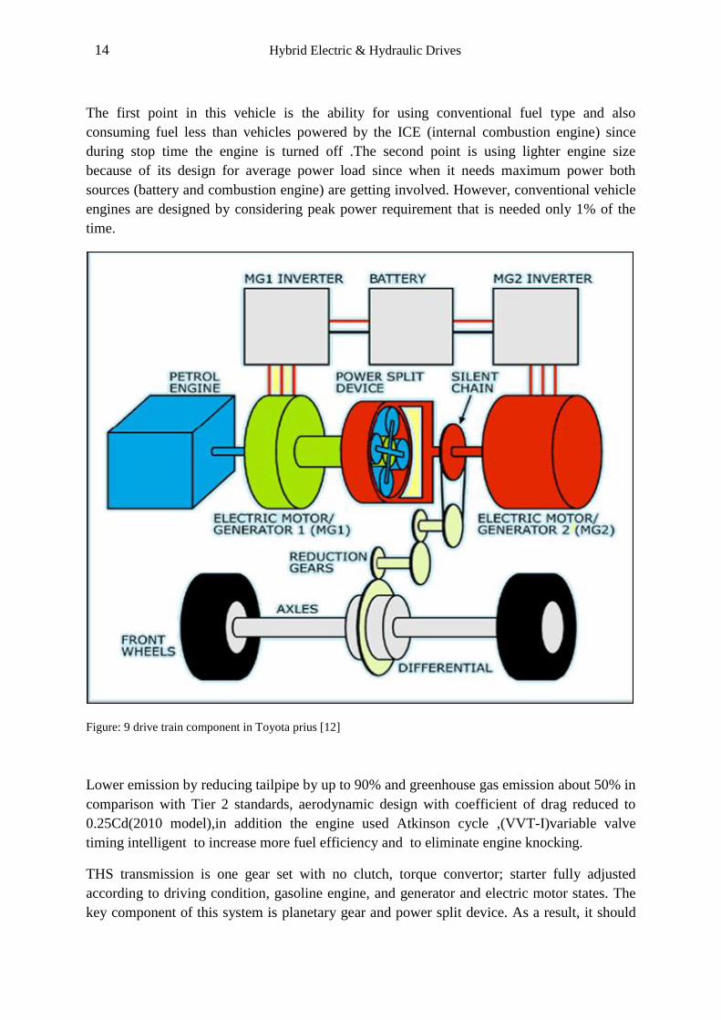
The first point in this vehicle is the ability for using conventional fuel type and also
consuming fuel less than vehicles powered by the ICE (internal combustion engine) since
during stop time the engine is turned off .The second point is using lighter engine size
because of its design for average power load since when it needs maximum power both
sources (battery and combustion engine) are getting involved. However, conventional vehicle
engines are designed by considering peak power requirement that is needed only 1% of the
time.
Figure: 9 drive train component in Toyota prius [12]
Lower emission by reducing tailpipe by up to 90% and greenhouse gas emission about 50% in
comparison with Tier 2 standards, aerodynamic design with coefficient of drag reduced to
0.25Cd(2010 model),in addition the engine used Atkinson cycle ,(VVT-I)variable valve
timing intelligent to increase more fuel efficiency and to eliminate engine knocking.
THS transmission is one gear set with no clutch, torque convertor; starter fully adjusted
according to driving condition, gasoline engine, and generator and electric motor states. The
key component of this system is planetary gear and power split device. As a result, it should
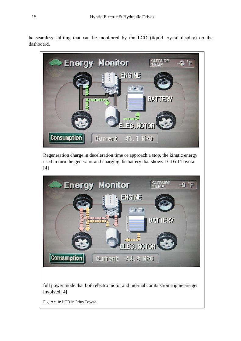
15 Hybrid Electric & Hydraulic Drives
be seamless shifting that can be monitored by the LCD (liquid crystal display) on the
dashboard.
Regeneration charge in deceleration time or approach a stop, the kinetic energy
used to turn the generator and charging the battery that shows LCD of Toyota
[4]
full power mode that both electro motor and internal combustion engine are get
involved [4]
Figure: 10: LCD in Prius Toyota.
16 Hybrid Electric & Hydraulic Drives
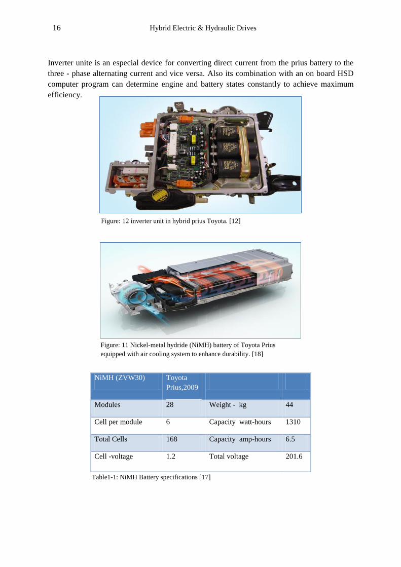
Inverter unite is an especial device for converting direct current from the prius battery to the
three - phase alternating current and vice versa. Also its combination with an on board HSD
computer program can determine engine and battery states constantly to achieve maximum
efficiency.
NiMH (ZVW30) Toyota
Prius,2009
Modules 28 Weight - kg 44
Cell per module 6 Capacity watt-hours 1310
Total Cells 168 Capacity amp-hours 6.5
Cell -voltage 1.2 Total voltage 201.6
Table1-1: NiMH Battery specifications [17]
Figure: 12 inverter unit in hybrid prius Toyota. [12]
Figure: 11 Nickel-metal hydride (NiMH) battery of Toyota Prius
equipped with air cooling system to enhance durability. [18]
17 Hybrid Electric & Hydraulic Drives
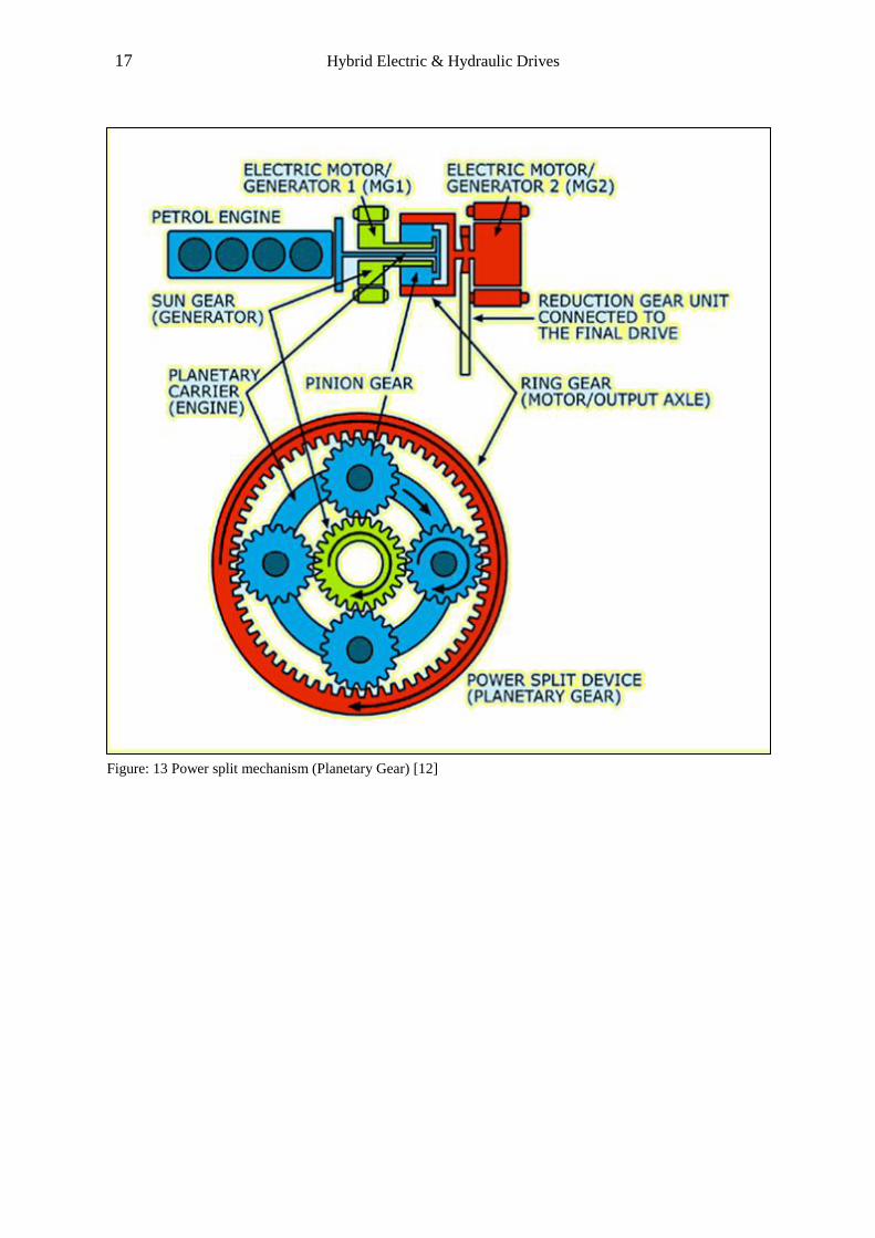
Figure: 13 Power split mechanism (Planetary Gear) [12]

18 Hybrid Electric & Hydraulic Drives
The hybrid synergy drive power splitting device distributes the power from ICE (internal
combustion engine) to the drive wheels or generator efficiently. Besides;
Power split device plays role of a gearbox so there is no a step gearbox
(manual/automatic).
Power split device is connected to the wheel directly so it doesn’t need a clutch or a
converter.
With a power split device, electro motor/generator play role of starter.
Electric power is generated by the motor/generator instead of alternator.
1.8 HRB-Hydrostatic/Hydraulic regenerative braking system
Bosch Rexroth is a pioneer company that offers hydraulic accumulators in HRB system both
in series and parallel models for different applications. However, some initial conditions are
necessary for using this system efficiently :
High Potential energy level (i.e., Heavy vehicle that has a large amount of kinetic
energy at deceleration times).
Frequently braking and accelerating is the second condition that is necessary for HRB
optimal application.
Figure: 14 Illustrate braking frequency and power in different machines [2]
19 Hybrid Electric & Hydraulic Drives
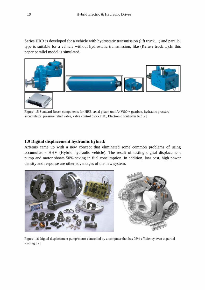
Series HRB is developed for a vehicle with hydrostatic transmission (lift truck…) and parallel
type is suitable for a vehicle without hydrostatic transmission, like (Refuse truck…).In this
paper parallel model is simulated.
Figure: 15 Standard Bosch components for HRB, axial piston unit A4VSO + gearbox, hydraulic pressure
accumulator, pressure relief valve, valve control block HIC, Electronic controller RC [2]
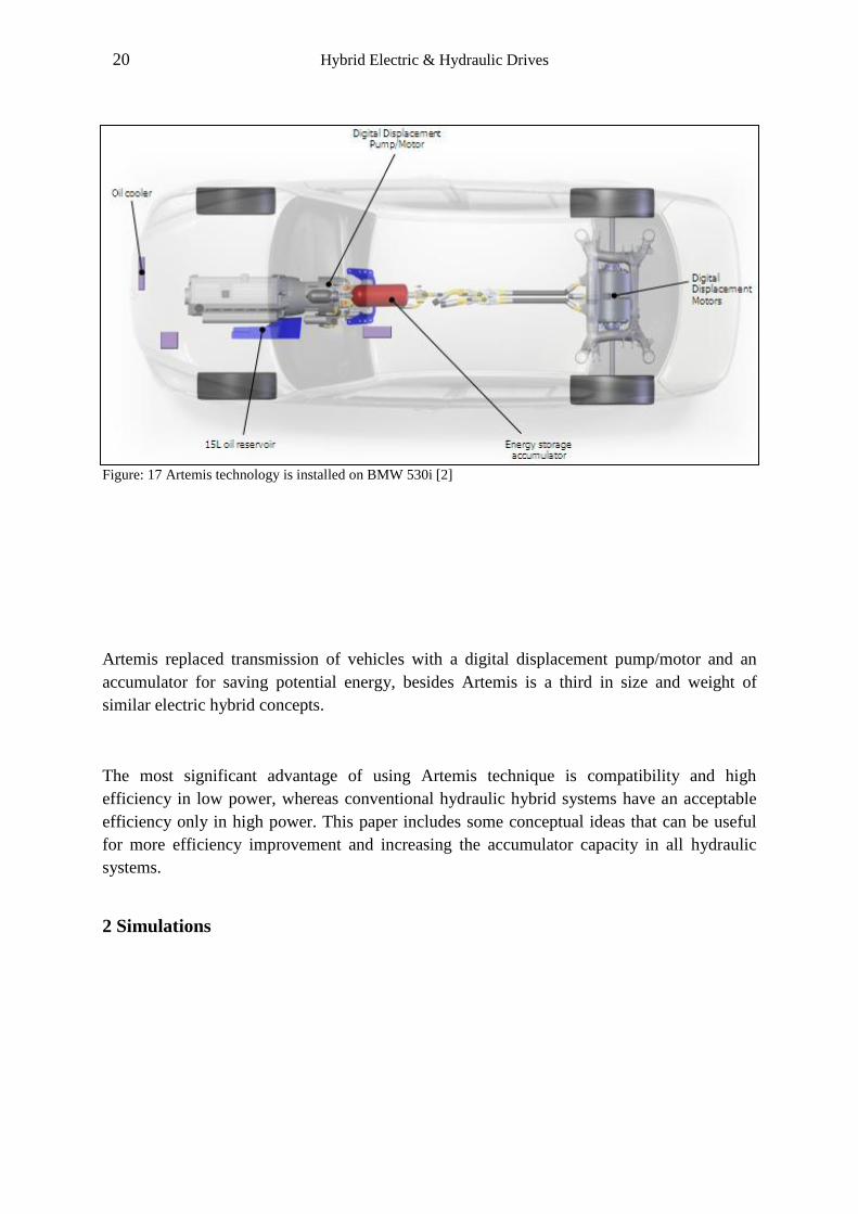
1.9 Digital displacement hydraulic hybrid:
Artemis came up with a new concept that eliminated some common problems of using
accumulators HHV (Hybrid hydraulic vehicle). The result of testing digital displacement
pump and motor shows 50% saving in fuel consumption. In addition, low cost, high power
density and response are other advantages of the new system.
Figure: 16 Digital displacement pump/motor controlled by a computer that has 95% efficiency even at partial
loading. [2]
20 Hybrid Electric & Hydraulic Drives
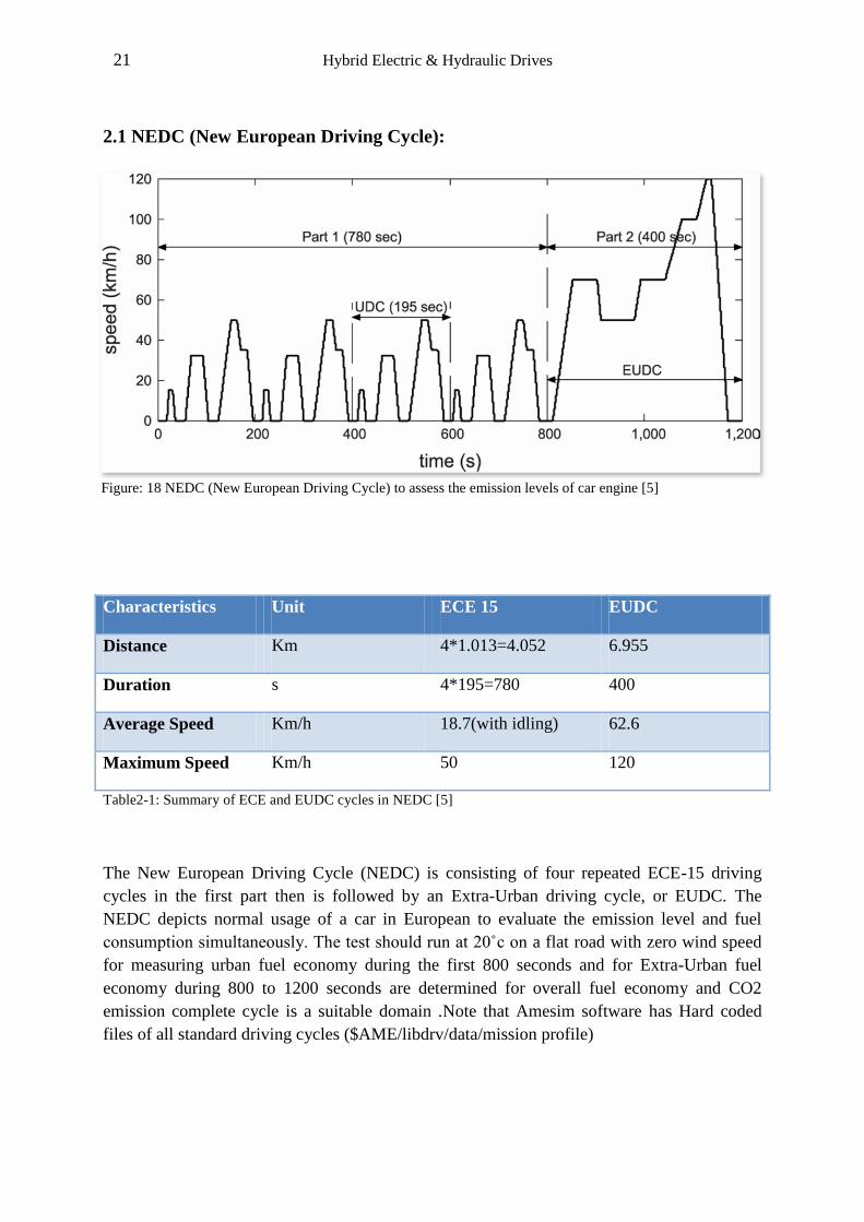
Figure: 17 Artemis technology is installed on BMW 530i [2]
Artemis replaced transmission of vehicles with a digital displacement pump/motor and an
accumulator for saving potential energy, besides Artemis is a third in size and weight of
similar electric hybrid concepts.
The most significant advantage of using Artemis technique is compatibility and high
efficiency in low power, whereas conventional hydraulic hybrid systems have an acceptable
efficiency only in high power. This paper includes some conceptual ideas that can be useful
for more efficiency improvement and increasing the accumulator capacity in all hydraulic
systems.
2 Simulations
21 Hybrid Electric & Hydraulic Drives
2.1 NEDC (New European Driving Cycle):
Characteristics Unit ECE 15 EUDC
Distance Km 4*1.013=4.052 6.955
Duration s 4*195=780 400
Average Speed Km/h 18.7(with idling) 62.6
Maximum Speed Km/h 50 120
Table2-1: Summary of ECE and EUDC cycles in NEDC [5]
The New European Driving Cycle (NEDC) is consisting of four repeated ECE-15 driving
cycles in the first part then is followed by an Extra-Urban driving cycle, or EUDC. The
NEDC depicts normal usage of a car in European to evaluate the emission level and fuel
consumption simultaneously. The test should run at 20˚с on a flat road with zero wind speed
for measuring urban fuel economy during the first 800 seconds and for Extra-Urban fuel
economy during 800 to 1200 seconds are determined for overall fuel economy and CO2
emission complete cycle is a suitable domain .Note that Amesim software has Hard coded
files of all standard driving cycles ($AME/libdrv/data/mission profile)
Figure: 18 NEDC (New European Driving Cycle) to assess the emission levels of car engine [5]
22 Hybrid Electric & Hydraulic Drives
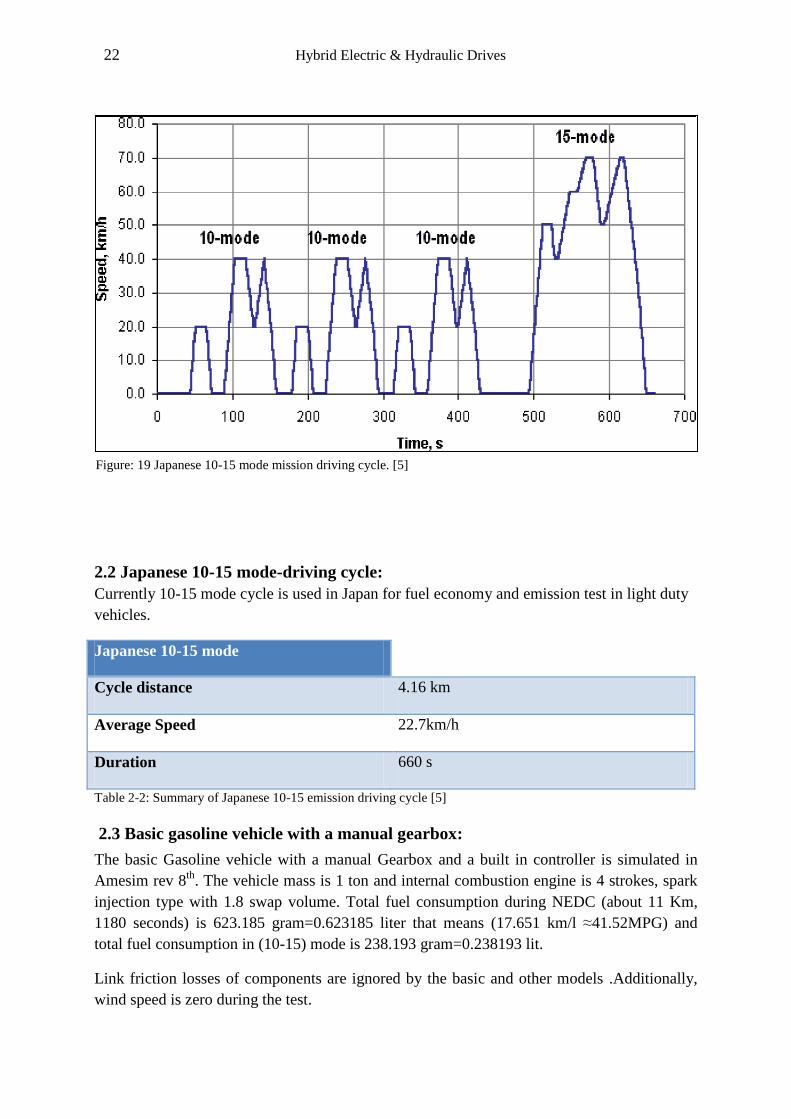
2.2 Japanese 10-15 mode-driving cycle:
Currently 10-15 mode cycle is used in Japan for fuel economy and emission test in light duty
vehicles.
Japanese 10-15 mode
Cycle distance 4.16 km
Average Speed 22.7km/h
Duration 660 s
Table 2-2: Summary of Japanese 10-15 emission driving cycle [5]
2.3 Basic gasoline vehicle with a manual gearbox:
The basic Gasoline vehicle with a manual Gearbox and a built in controller is simulated in
Amesim rev 8th
. The vehicle mass is 1 ton and internal combustion engine is 4 strokes, spark
injection type with 1.8 swap volume. Total fuel consumption during NEDC (about 11 Km,
1180 seconds) is 623.185 gram=0.623185 liter that means (17.651 km/l ≈41.52MPG) and
total fuel consumption in (10-15) mode is 238.193 gram=0.238193 lit.
Link friction losses of components are ignored by the basic and other models .Additionally,
wind speed is zero during the test.
Figure: 19 Japanese 10-15 mode mission driving cycle. [5]
23 Hybrid Electric & Hydraulic Drives
Figure: 21 Gearbox ratio control (Basic Model) During NEDC
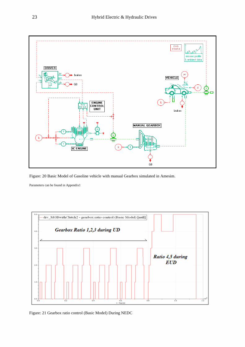
Figure: 20 Basic Model of Gasoline vehicle with manual Gearbox simulated in Amesim.
Parameters can be found in Appendix1
24 Hybrid Electric & Hydraulic Drives
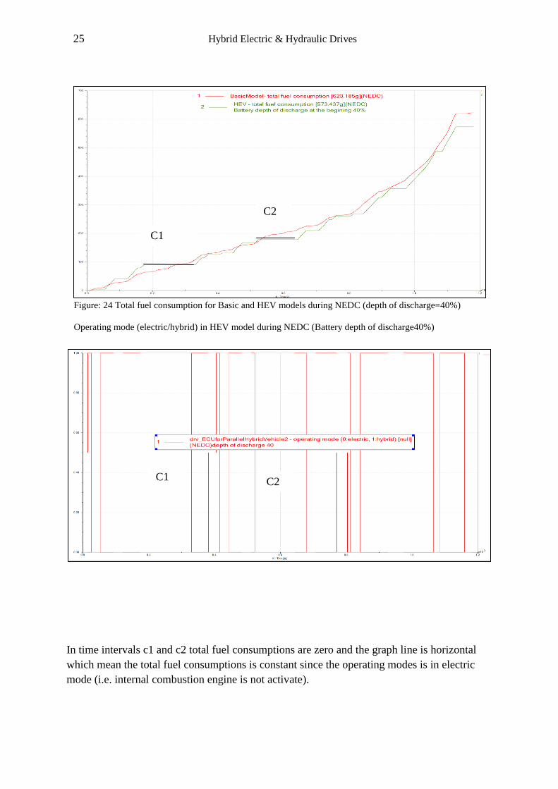
2.4 Parallel hybrid electric vehicle: The main role of a controller in a HEV model is
ability for following mission profiles.
Figure: 22 Parallel hybrid Electric with a manual Gearbox in Amesim. Parameters can be found in Appendix3
Figure: 23 NEDC profile in collusion with the vehicle speed accurately
25 Hybrid Electric & Hydraulic Drives
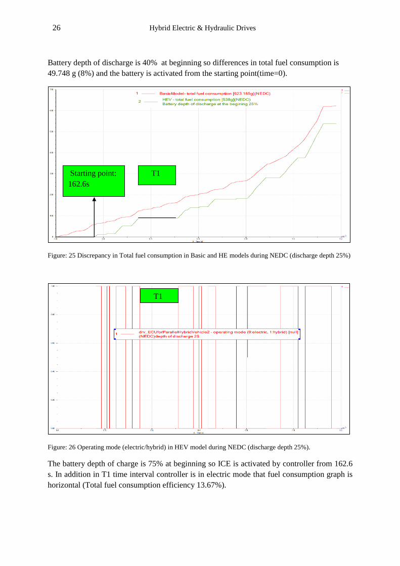
In time intervals c1 and c2 total fuel consumptions are zero and the graph line is horizontal
which mean the total fuel consumptions is constant since the operating modes is in electric
mode (i.e. internal combustion engine is not activate).
C2
Figure: 24 Total fuel consumption for Basic and HEV models during NEDC (depth of discharge=40%)
Operating mode (electric/hybrid) in HEV model during NEDC (Battery depth of discharge40%)
C1
C1
C2
26 Hybrid Electric & Hydraulic Drives
Battery depth of discharge is 40% at beginning so differences in total fuel consumption is
49.748 g (8%) and the battery is activated from the starting point(time=0).
Figure: 25 Discrepancy in Total fuel consumption in Basic and HE models during NEDC (discharge depth 25%)
Figure: 26 Operating mode (electric/hybrid) in HEV model during NEDC (discharge depth 25%).
The battery depth of charge is 75% at beginning so ICE is activated by controller from 162.6
s. In addition in T1 time interval controller is in electric mode that fuel consumption graph is
horizontal (Total fuel consumption efficiency 13.67%).
Starting point:
162.6s
T1
T1

27 Hybrid Electric & Hydraulic Drives
Battery state of charge is 75% and starting point for using ICE power is 236s that is longer
than 162.6s in figure(0-15) because 10-15 cycle has a lower average speed and distance in
comparison with NEDC.
Starting
point: 236s
Figure: 27 Discrepancy in total fuel consumption during (10-15) in HEV (discharge depth 25%).
Figure: 28 Operating mode (electric/hybrid) in HEV model during Japanese driving cycle (10-15) (discharge
depth 25%)
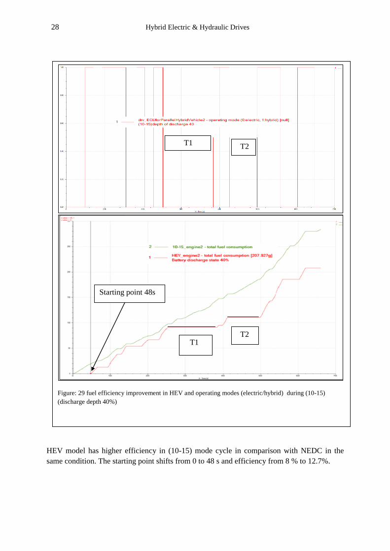
28 Hybrid Electric & Hydraulic Drives
HEV model has higher efficiency in (10-15) mode cycle in comparison with NEDC in the
same condition. The starting point shifts from 0 to 48 s and efficiency from 8 % to 12.7%.
Figure: 29 fuel efficiency improvement in HEV and operating modes (electric/hybrid) during (10-15)
(discharge depth 40%)
Starting point 48s
T1 T2
T1 T2
29 Hybrid Electric & Hydraulic Drives
Figure 2-18: Exhaust gas flow rate in HEV models during NEDC (discharge depth 25%)
HEV
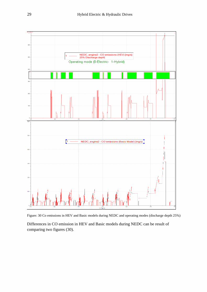
Figure: 30 Co emissions in HEV and Basic models during NEDC and operating modes (discharge depth 25%)
Differences in CO emission in HEV and Basic models during NEDC can be result of
comparing two figures (30).
30 Hybrid Electric & Hydraulic Drives
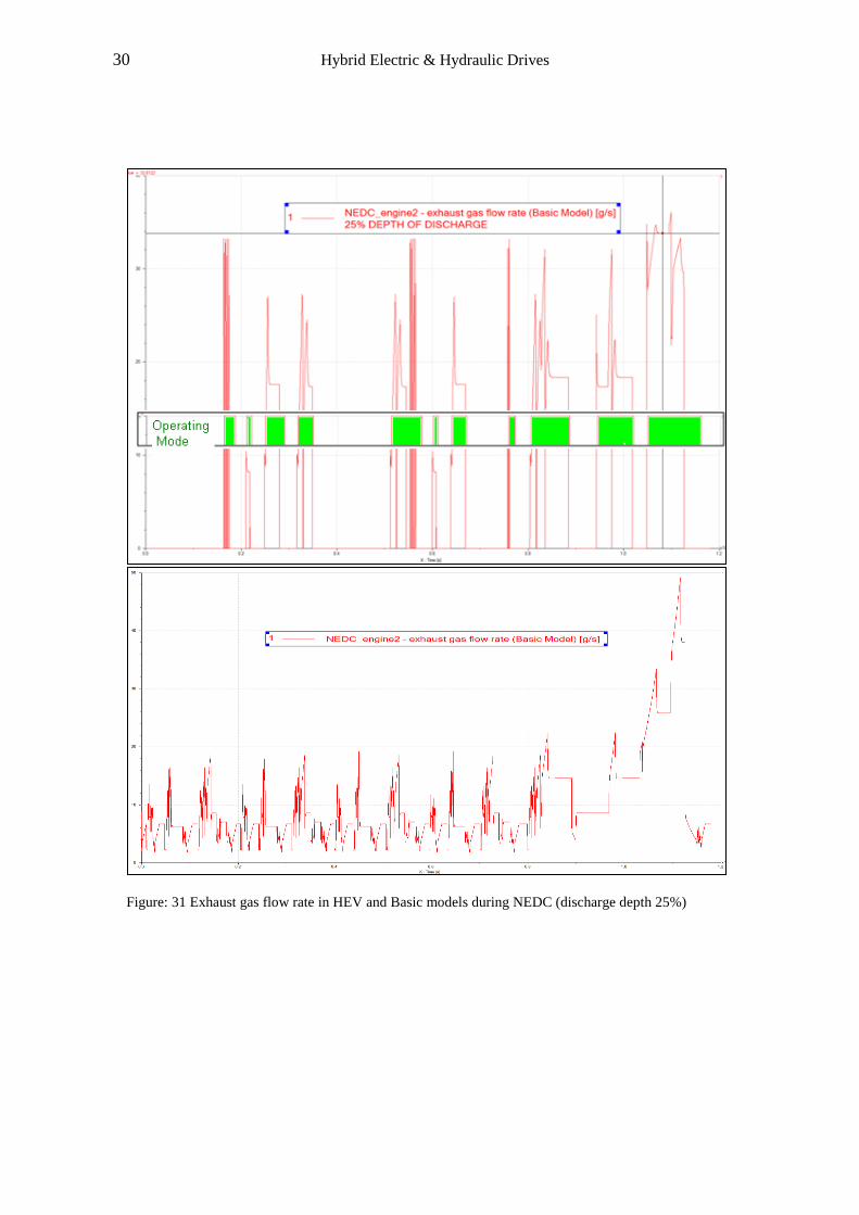
Figure: 31 Exhaust gas flow rate in HEV and Basic models during NEDC (discharge depth 25%)
31 Hybrid Electric & Hydraulic Drives
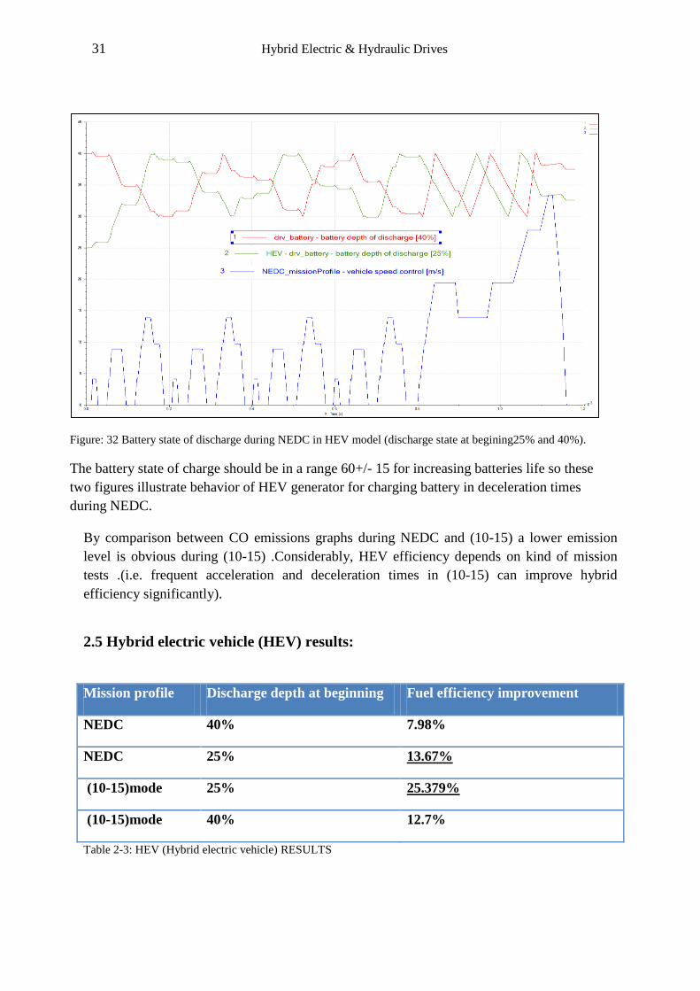
By comparison between CO emissions graphs during NEDC and (10-15) a lower emission
level is obvious during (10-15) .Considerably, HEV efficiency depends on kind of mission
tests .(i.e. frequent acceleration and deceleration times in (10-15) can improve hybrid
efficiency significantly).
2.5 Hybrid electric vehicle (HEV) results:
Mission profile Discharge depth at beginning Fuel efficiency improvement
NEDC 40% 7.98%
NEDC 25% 13.67%
(10-15)mode 25% 25.379%
(10-15)mode 40% 12.7%
Table 2-3: HEV (Hybrid electric vehicle) RESULTS
Figure 2-19: Battery state of discharge and operating modes in HEV during NEDC (discharge depth 40%)
Figure: 32 Battery state of discharge during NEDC in HEV model (discharge state at begining25% and 40%).
The battery state of charge should be in a range 60+/- 15 for increasing batteries life so these
two figures illustrate behavior of HEV generator for charging battery in deceleration times
during NEDC.
32 Hybrid Electric & Hydraulic Drives
Overall efficiency improvement in Japanese driving cycle (10-15) is higher than NEDC
because Japanese driving cycle has more frequent acceleration and braking cycles in a shorter
duration (660s) in comparison with NEDC (1180s).In addition shorter distance (4.16km) in
Japanese driving cycle (10-15) mode gives more opportunity for using the battery saved
energy instead of using ICE (internal combustion engine) power.
2.6 Battery state of charge:
Most of the companies allow neither fully charge state100% nor less than 40% to get a
maximum NiMH batteries life. For example Toyota prius battery like to be kept 60+/-15
percent (i.e. the battery charge rarely upper 75% and lower 45% state of charge)(Figure 32).
2.7 Comparing basic and HEV (Hybrid electric vehicles):
Hybrid Electric technique is more efficient and achieves a higher fuel efficiency improvement
in 10-15 mode (Japanese driving cycle) .Since it has more frequent acceleration and
deceleration (braking) times at shorter duration and distance(660s-4.6km) in comparison to
NEDC(1180s-11km).
HEV model is simulated in (10-15) with the battery charging state 75%. Thus (figure 27)
shows until 236 seconds only the electromotor and battery are involved to produce energy
then ICE (internal combustion engine) is activated by the controller, fuel consumption graph
increase dramatically while the operating mode is in hybrid state (figure28).Figures (30-31)
show same trend like the fuel consumption graph i.e. increasing different emissions.
Overall fuel improvement is (238.193-177.741=60.452gr) which means the basic model has
41.08 MPG and HEV reaches 55 MPG that shows 14 MPG increase (about 25%) that is
acceptable. However, expensive components and high cost maintenance are other side of the
topic. In addition, parallel system used ICE internal combustion engine as it required. This
means efficiency will vary.
In other words, at high speed HEV has a better performance since the ICE (internal
combustion engine) has a function as the primary power source with the electric motor that
provide an extra power when needed . Parallel HEV doesn’t have the ability to be used as a
full electric hybrid car in a short trip. That is an advantage of Series systems or a combined
system of parallel and series systems with an advanced computer in a Toyota Prius in which
all positive points are available.

33 Hybrid Electric & Hydraulic Drives
Figure: 33 Pump shaft speed diagram in HHV during NEDC (maximum=1955.93rpm).
Gear box play an important role of reducer to keep pump shaft speed under the maximum
pump speed during NEDC.
3. Hybrid hydraulic vehicle (HHV)
3.1 Hydraulic regenerative braking system (HRB)
Bosch Company offered HRB to the vehicle market in two forms; series HRB for vehicles
that have a hydrostatic transmission such as forklift and parallel HRB for vehicles without
hydrostatic transmission like refuse trucks or buses. Using HRB system improves fuel
efficiency and acceleration significantly but depending on applications. Focus of this paper is
mainly on HRB parallel model that Bosch Rexroth installed on a refuse truck.
Amesim rev 8th doesn’t have a standard controller for simulating parallel HRB so we try to
install the system in a Basic Model with a gasoline engine and a manual Gearbox .New
system has extra components as follows; Axial piston pump and motor, Hydraulic
Accumulator, pressure relief valve, 2/3 directional valve, 2/2 directional valve, check valve
34 Hybrid Electric & Hydraulic Drives
and two gears that play role of the Gearbox for keeping pump and motor speed in a standard
range that is mentioned in catalogues.
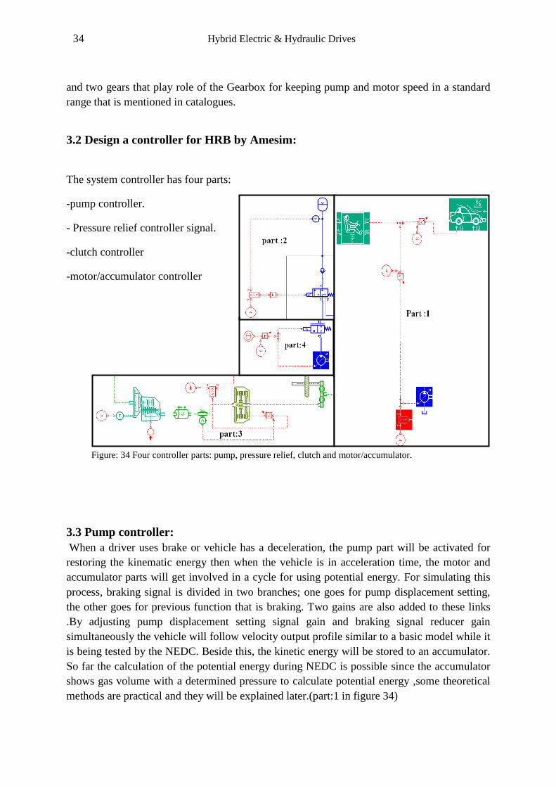
3.2 Design a controller for HRB by Amesim:
The system controller has four parts:
-pump controller.
- Pressure relief controller signal.
-clutch controller
-motor/accumulator controller
3.3 Pump controller:
When a driver uses brake or vehicle has a deceleration, the pump part will be activated for
restoring the kinematic energy then when the vehicle is in acceleration time, the motor and
accumulator parts will get involved in a cycle for using potential energy. For simulating this
process, braking signal is divided in two branches; one goes for pump displacement setting,
the other goes for previous function that is braking. Two gains are also added to these links
.By adjusting pump displacement setting signal gain and braking signal reducer gain
simultaneously the vehicle will follow velocity output profile similar to a basic model while it
is being tested by the NEDC. Beside this, the kinetic energy will be stored to an accumulator.
So far the calculation of the potential energy during NEDC is possible since the accumulator
shows gas volume with a determined pressure to calculate potential energy ,some theoretical
methods are practical and they will be explained later.(part:1 in figure 34)
Figure: 34 Four controller parts: pump, pressure relief, clutch and motor/accumulator.
35 Hybrid Electric & Hydraulic Drives
3.4 Motor / Accumulator controller:
The next step of a completed cycle, is consuming the potential energy. The motor and its
valve controller are managed by the data stored in an ASCII data file ( UDA01 is a duty cycle
sub model which the output U is a function of time and data computed by linear
interpolation). This signal is responsible for adjusting motor displacement setting and
discharging the high pressure accumulator by opening the 2/2 directional valve. (Part 4 in
figure 34)
3.5 Pressure relief controller:
In addition to the pressure relief valve that protects system of a maximum pressure, one
sensor and a conditional controller will check the accumulator pressure continuously as the
accumulator reaches the maximum pressure in a fully charge condition the controller signal
will change the direction of 2/3 directional valve to the tank.(part 2 in figure 34)
3.6 Clutch controller:
In reality, ICE (internal combustion engine) and the link that connects it to the Gearbox have
a significant inertia that can eliminate huge amount of the vehicle kinetic energy in a braking
time, so this controller separates them form the system for sending and saving all kinetic
energy as a hydraulic power to the accumulator.(part 3 in figure 34)
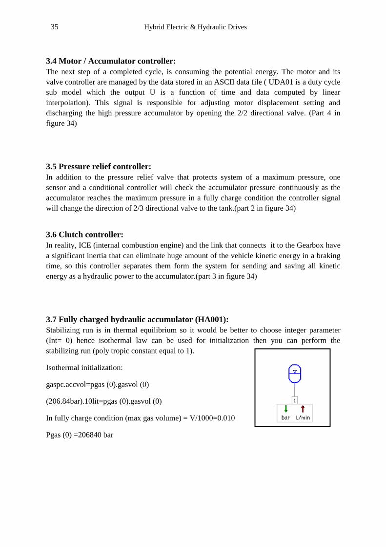
3.7 Fully charged hydraulic accumulator (HA001):
Stabilizing run is in thermal equilibrium so it would be better to choose integer parameter
(Int= 0) hence isothermal law can be used for initialization then you can perform the
stabilizing run (poly tropic constant equal to 1).
Isothermal initialization:
gaspc.accvol=pgas (0).gasvol (0)
(206.84bar).10lit=pgas (0).gasvol (0)
In fully charge condition (max gas volume) = V/1000=0.010
Pgas (0) =206840 bar
36 Hybrid Electric & Hydraulic Drives
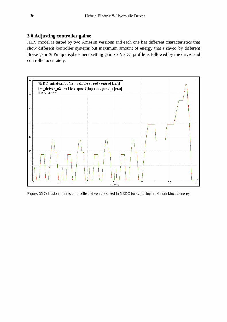
3.8 Adjusting controller gains:
HHV model is tested by two Amesim versions and each one has different characteristics that
show different controller systems but maximum amount of energy that’s saved by different
Brake gain & Pump displacement setting gain so NEDC profile is followed by the driver and
controller accurately.
Figure: 35 Collusion of mission profile and vehicle speed in NEDC for capturing maximum kinetic energy
37 Hybrid Electric & Hydraulic Drives
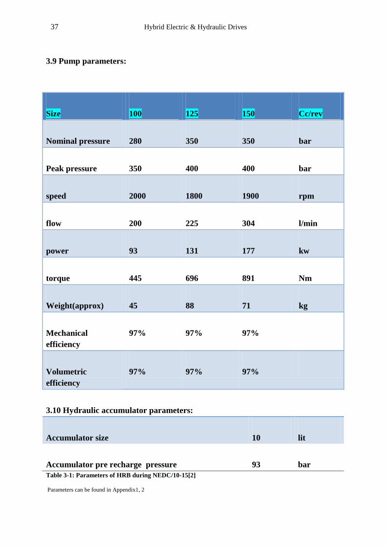
3.9 Pump parameters:
3.10 Hydraulic accumulator parameters:
Accumulator size 10 lit
Accumulator pre recharge pressure 93 bar
Table 3-1: Parameters of HRB during NEDC/10-15[2]
Parameters can be found in Appendix1, 2
Size 100 125 150 Cc/rev
Nominal pressure 280 350 350 bar
Peak pressure 350 400 400 bar
speed 2000 1800 1900 rpm
flow 200 225 304 l/min
power 93 131 177 kw
torque 445 696 891 Nm
Weight(approx) 45 88 71 kg
Mechanical
efficiency
97% 97% 97%
Volumetric
efficiency
97% 97% 97%
38 Hybrid Electric & Hydraulic Drives
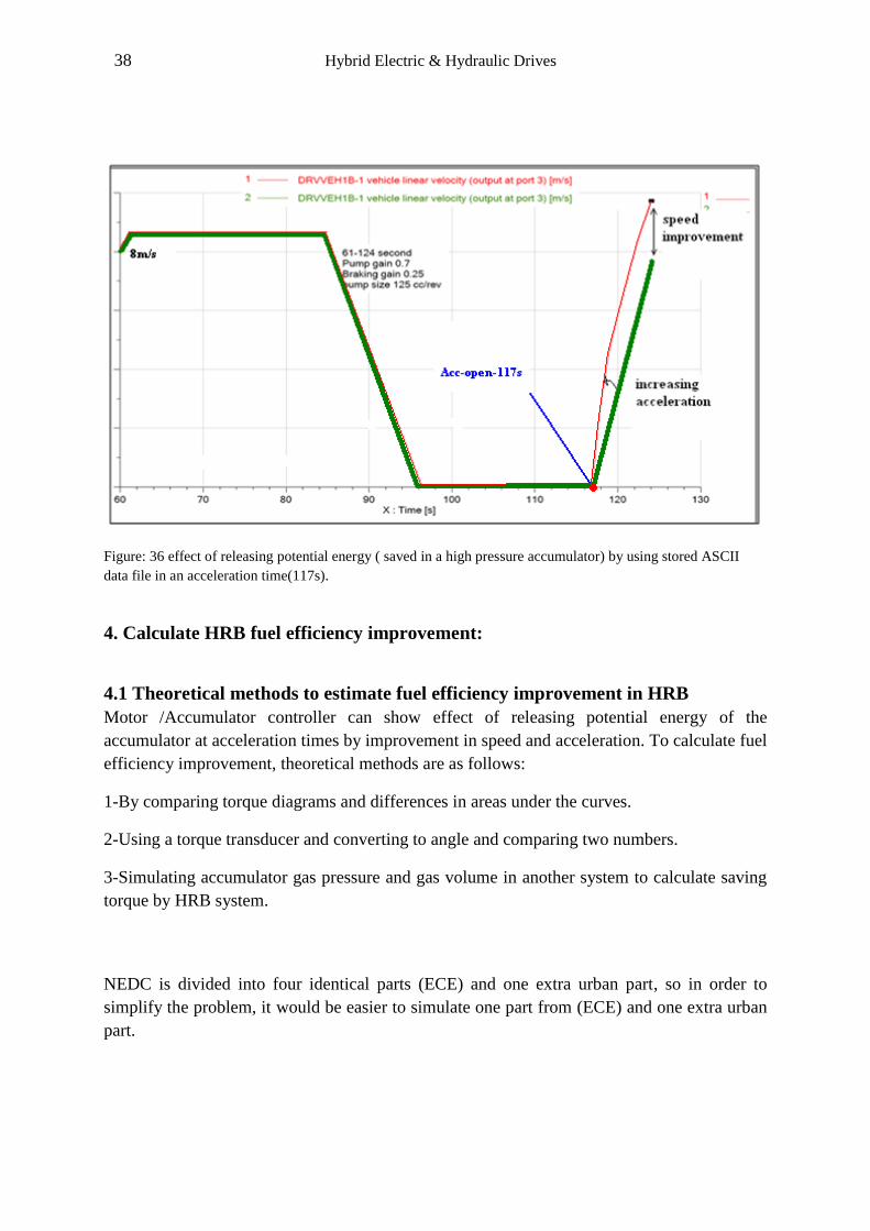
Figure: 36 effect of releasing potential energy ( saved in a high pressure accumulator) by using stored ASCII
data file in an acceleration time(117s).
4. Calculate HRB fuel efficiency improvement:
4.1 Theoretical methods to estimate fuel efficiency improvement in HRB
Motor /Accumulator controller can show effect of releasing potential energy of the
accumulator at acceleration times by improvement in speed and acceleration. To calculate fuel
efficiency improvement, theoretical methods are as follows:
1-By comparing torque diagrams and differences in areas under the curves.
2-Using a torque transducer and converting to angle and comparing two numbers.
3-Simulating accumulator gas pressure and gas volume in another system to calculate saving
torque by HRB system.
NEDC is divided into four identical parts (ECE) and one extra urban part, so in order to
simplify the problem, it would be easier to simulate one part from (ECE) and one extra urban
part.

39 Hybrid Electric & Hydraulic Drives
Figure: 38 Engine and pump torque diagrams during NEDC.
Figure: 37 shows charging and discharging Accumulator positions in (0-206seconds).
40 Hybrid Electric & Hydraulic Drives
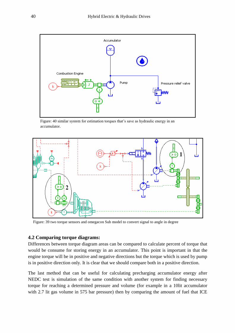
4.2 Comparing torque diagrams:
Differences between torque diagram areas can be compared to calculate percent of torque that
would be consume for storing energy in an accumulator. This point is important in that the
engine torque will be in positive and negative directions but the torque which is used by pump
is in positive direction only. It is clear that we should compare both in a positive direction.
The last method that can be useful for calculating precharging accumulator energy after
NEDC test is simulation of the same condition with another system for finding necessary
torque for reaching a determined pressure and volume (for example in a 10lit accumulator
with 2.7 lit gas volume in 575 bar pressure) then by comparing the amount of fuel that ICE
Figure: 40 similar system for estimation torques that’s save as hydraulic energy in an
accumulator.
Figure: 39 two torque sensors and omegacon Sub model to convert signal to angle in degree
41 Hybrid Electric & Hydraulic Drives
(internal combustion engine) needs to provide this amount of torque, improvement in fuel
efficiency is of estimable Results.
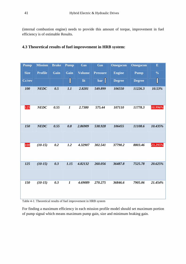
4.3 Theoretical results of fuel improvement in HRB system:
Pump
Size
Cc/rev
Mission
Profile
Brake
Gain
Pump
Gain
Gas
Volume
lit
Gas
Pressure
bar
Omegacon
Engine
Degree
Omegacon
Pump
Degree
E
%
100 NEDC 0.5 1.1 2.8281 549.899 106550 11226.3 10.53%
125 NEDC 0.55 1 2.7380 575.44
107110 11778.3 10.996%
150 NEDC 0.55 0.8 2.86909 538.928 106455 11108.6 10.435%
100 (10-15) 0.2 1.2 4.32907 302.541 37790.2 8803.46 23.295%
125 (10-15) 0.3 1.15 4.82132 260.056 36487.8 7525.78 20.625%
150 (10-15) 0.3 1 4.69089 270.275 36846.6 7905.06 21.454%
Table 4-1: Theoretical results of fuel improvement in HRB system
For finding a maximum efficiency in each mission profile model should set maximum portion
of pump signal which means maximum pump gain, size and minimum braking gain.
42 Hybrid Electric & Hydraulic Drives
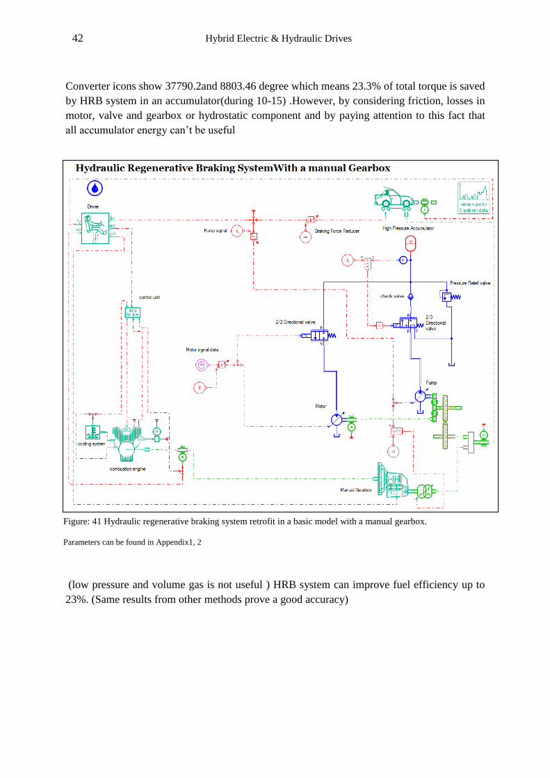
Converter icons show 37790.2and 8803.46 degree which means 23.3% of total torque is saved
by HRB system in an accumulator(during 10-15) .However, by considering friction, losses in
motor, valve and gearbox or hydrostatic component and by paying attention to this fact that
all accumulator energy can’t be useful
(low pressure and volume gas is not useful ) HRB system can improve fuel efficiency up to
23%. (Same results from other methods prove a good accuracy)
Figure: 41 Hydraulic regenerative braking system retrofit in a basic model with a manual gearbox.
Parameters can be found in Appendix1, 2
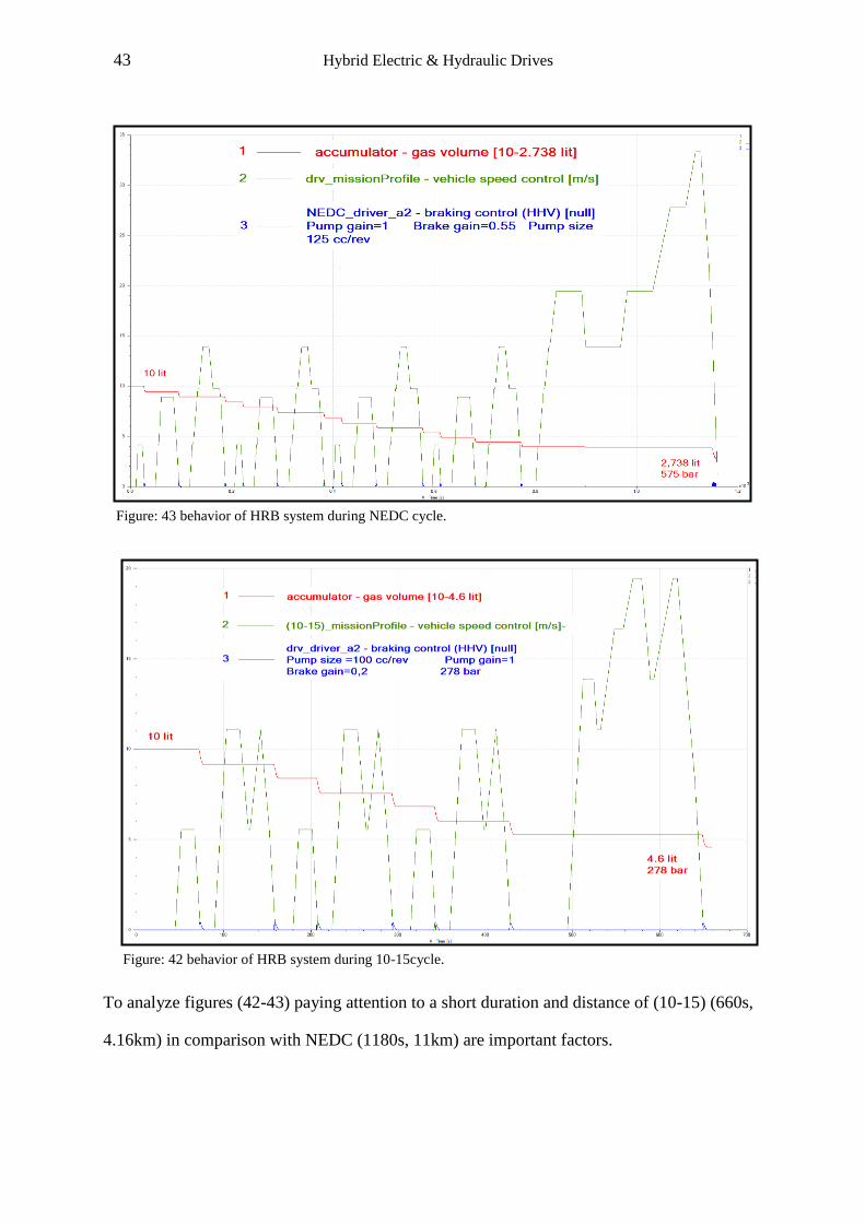
43 Hybrid Electric & Hydraulic Drives
To analyze figures (42-43) paying attention to a short duration and distance of (10-15) (660s,
4.16km) in comparison with NEDC (1180s, 11km) are important factors.
Figure: 43 behavior of HRB system during NEDC cycle.
Figure: 42 behavior of HRB system during 10-15cycle.
44 Hybrid Electric & Hydraulic Drives
Comparing between two systems with a small difference in maximum efficiency values is not
easy; so for evaluation should consider other factors. However, a big difference between
results in two standard mission profiles can prove a fix rule in hybridization: increasing
frequency of acceleration and deceleration times can improve fuel efficiency considerably. In
other words, (10-15) mode Japanese driving cycle has a shorter duration and distance which
means a higher frequency of acceleration and deceleration cycles and the ideal condition for
hybrid systems.
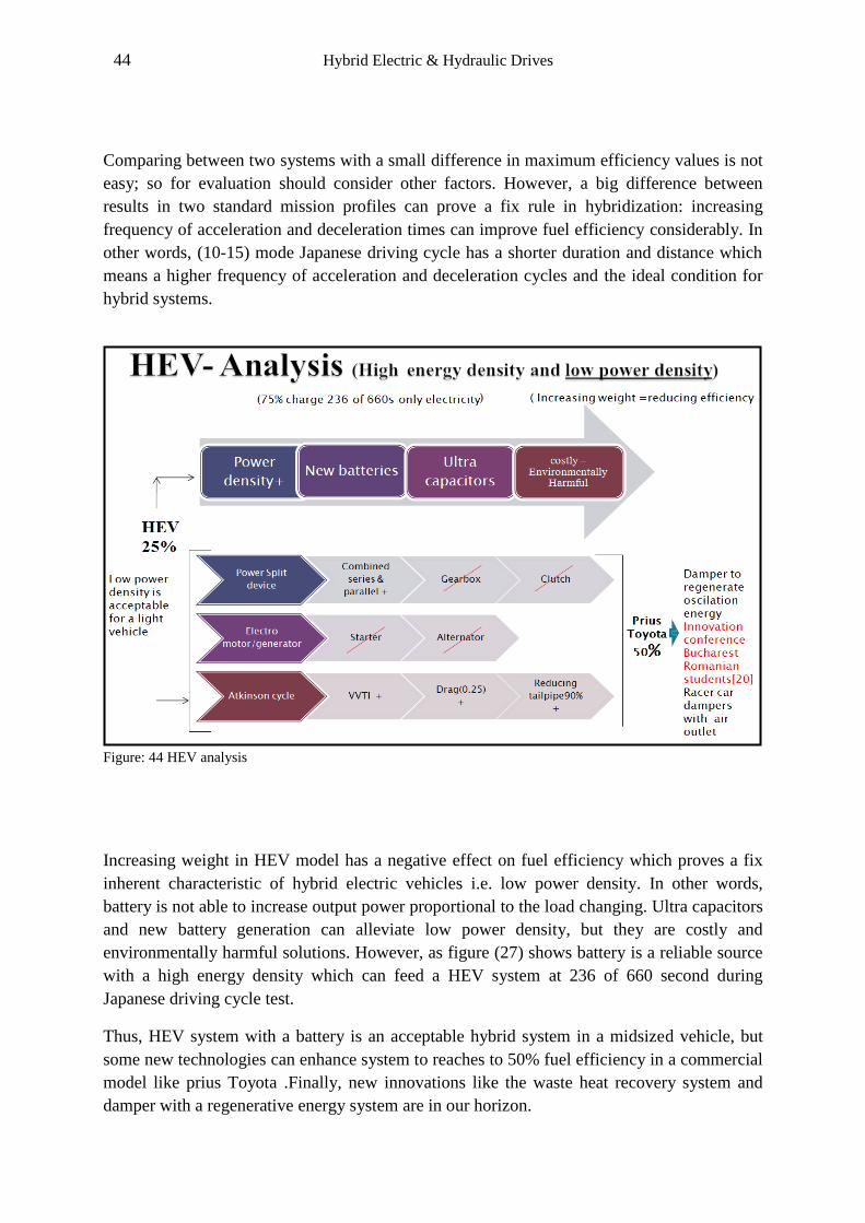
Figure: 44 HEV analysis
Increasing weight in HEV model has a negative effect on fuel efficiency which proves a fix
inherent characteristic of hybrid electric vehicles i.e. low power density. In other words,
battery is not able to increase output power proportional to the load changing. Ultra capacitors
and new battery generation can alleviate low power density, but they are costly and
environmentally harmful solutions. However, as figure (27) shows battery is a reliable source
with a high energy density which can feed a HEV system at 236 of 660 second during
Japanese driving cycle test.
Thus, HEV system with a battery is an acceptable hybrid system in a midsized vehicle, but
some new technologies can enhance system to reaches to 50% fuel efficiency in a commercial
model like prius Toyota .Finally, new innovations like the waste heat recovery system and
damper with a regenerative energy system are in our horizon.
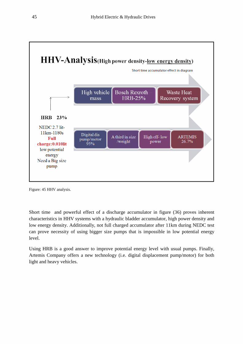
45 Hybrid Electric & Hydraulic Drives
Figure: 45 HHV analysis.
Short time and powerful effect of a discharge accumulator in figure (36) proves inherent
characteristics in HHV systems with a hydraulic bladder accumulator, high power density and
low energy density. Additionally, not full charged accumulator after 11km during NEDC test
can prove necessity of using bigger size pumps that is impossible in low potential energy
level.
Using HRB is a good answer to improve potential energy level with usual pumps. Finally,
Artemis Company offers a new technology (i.e. digital displacement pump/motor) for both
light and heavy vehicles.
46 Hybrid Electric & Hydraulic Drives
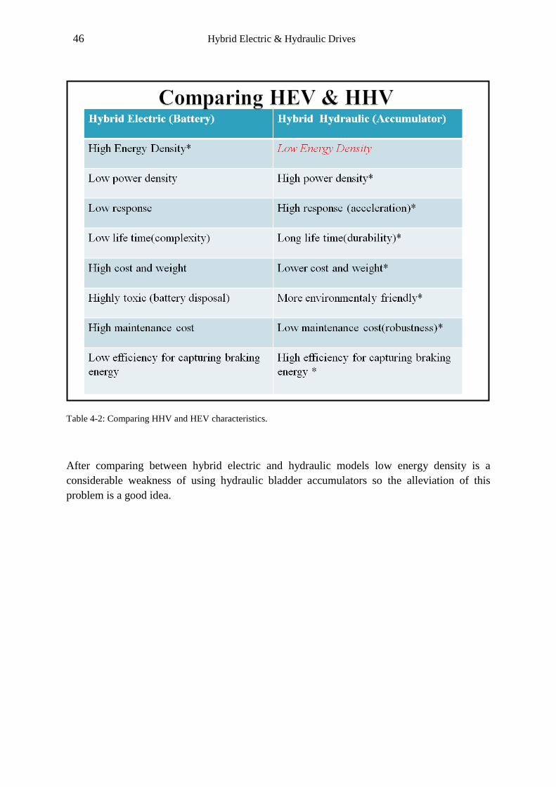
Table 4-2: Comparing HHV and HEV characteristics.
After comparing between hybrid electric and hydraulic models low energy density is a
considerable weakness of using hydraulic bladder accumulators so the alleviation of this
problem is a good idea.
47 Hybrid Electric & Hydraulic Drives
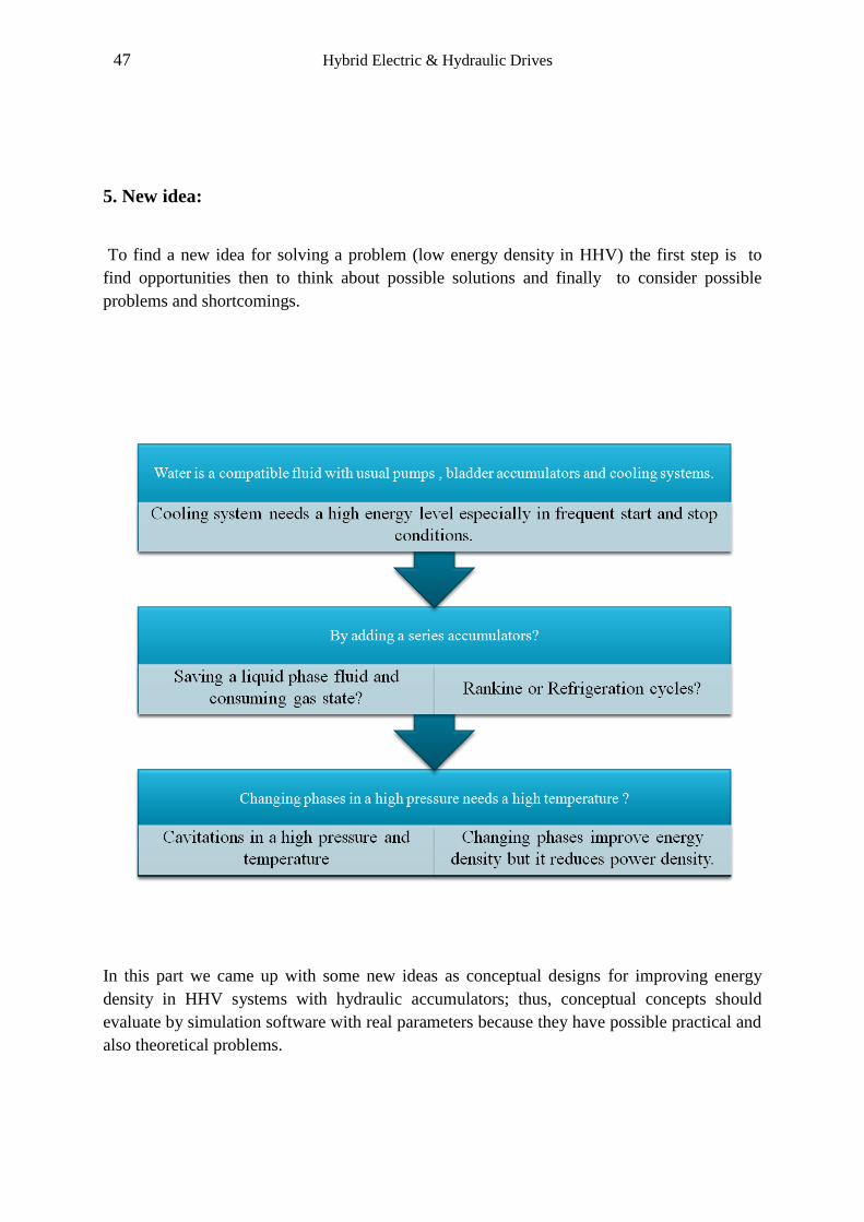
5. New idea:
To find a new idea for solving a problem (low energy density in HHV) the first step is to
find opportunities then to think about possible solutions and finally to consider possible
problems and shortcomings.
In this part we came up with some new ideas as conceptual designs for improving energy
density in HHV systems with hydraulic accumulators; thus, conceptual concepts should
evaluate by simulation software with real parameters because they have possible practical and
also theoretical problems.
48 Hybrid Electric & Hydraulic Drives
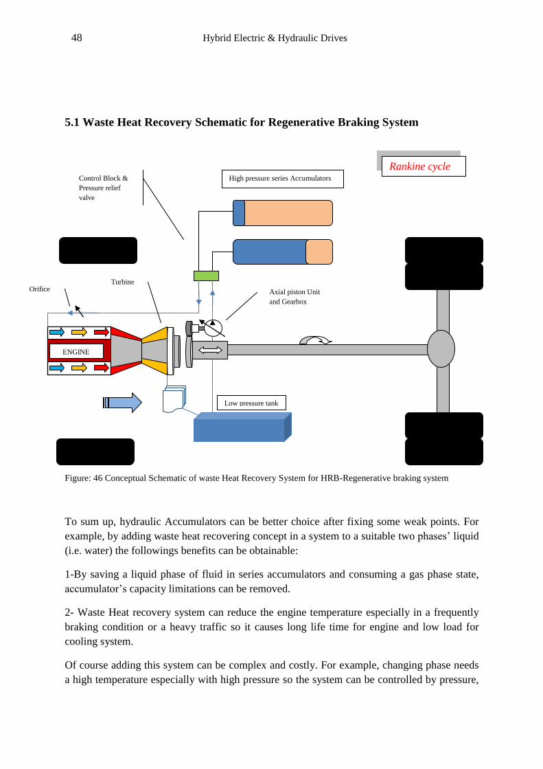
5.1 Waste Heat Recovery Schematic for Regenerative Braking System
Figure: 46 Conceptual Schematic of waste Heat Recovery System for HRB-Regenerative braking system
To sum up, hydraulic Accumulators can be better choice after fixing some weak points. For
example, by adding waste heat recovering concept in a system to a suitable two phases’ liquid
(i.e. water) the followings benefits can be obtainable:
1-By saving a liquid phase of fluid in series accumulators and consuming a gas phase state,
accumulator’s capacity limitations can be removed.
2- Waste Heat recovery system can reduce the engine temperature especially in a frequently
braking condition or a heavy traffic so it causes long life time for engine and low load for
cooling system.
Of course adding this system can be complex and costly. For example, changing phase needs
a high temperature especially with high pressure so the system can be controlled by pressure,
ENGINE
Low pressure tank
High pressure series Accumulators
Axial piston Unit
and Gearbox
Turbine
Control Block &
Pressure relief
valve
Orifice
Rankine cycle
49 Hybrid Electric & Hydraulic Drives
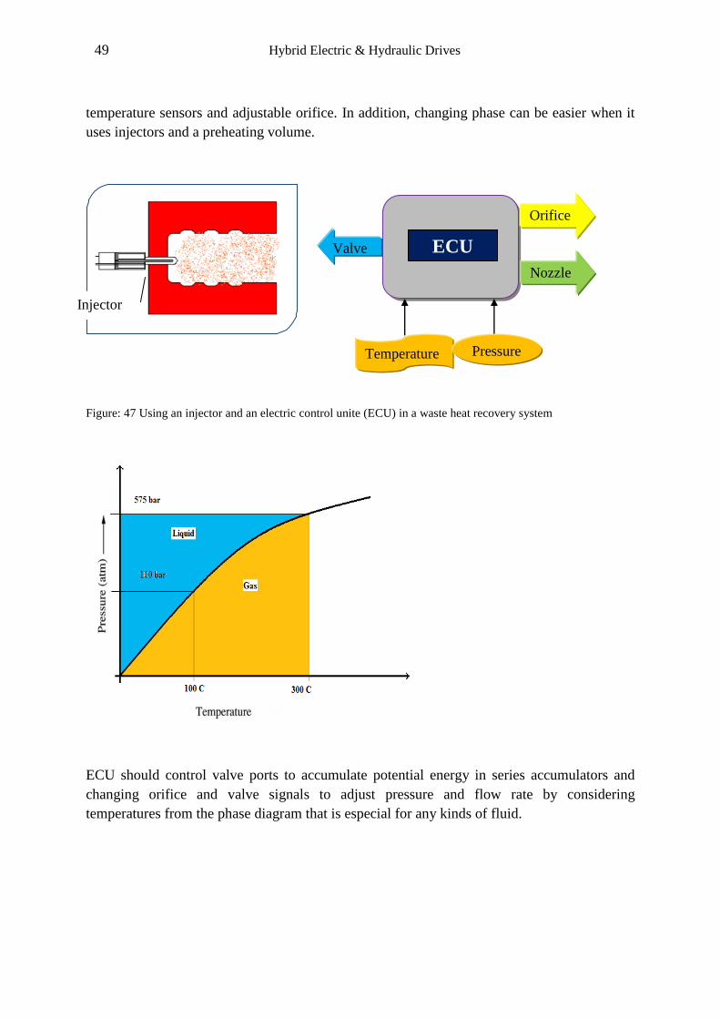
temperature sensors and adjustable orifice. In addition, changing phase can be easier when it
uses injectors and a preheating volume.
Figure: 47 Using an injector and an electric control unite (ECU) in a waste heat recovery system
ECU should control valve ports to accumulate potential energy in series accumulators and
changing orifice and valve signals to adjust pressure and flow rate by considering
temperatures from the phase diagram that is especial for any kinds of fluid.
Orifice
signal
Nozzle
Valve
Temperature Pressure
ECU
Injector

50 Hybrid Electric & Hydraulic Drives
5.2 Modification of Waste Heat Recovery Schematic for Regenerative Braking
System.
If regenerative braking energy is captured by a compressor and a pump simultaneously, then
the new system can save more braking energy and the new system has a good capacity for
saving and reusing regenerative energy for a longer time in comparison with the conventional
design since the modified system can save high pressure fluid in an accumulator and consume
energy in gas state.
Figure: 48 Modification of Waste Heat Recovery in HRB
Using a two- phase fluid and a pump as well as compressor can enhance capturing braking
energy level in deceleration and braking times.
5.3 Preheat volume:
Preheat Volume plays two roles: first of all, reducing huge differences in temperature between
a high pressure liquid accumulator temperature and the engine temperature for changing fluid
phases. Second of all, setting pressure and flow rate according to the sensor information
before changing phases. It’s noticeable that injecting a fluid with big differences in
temperatures can causes a tension and cracks in the engine block.
Work in
Work out
High Pressure
Accumulator
Pump
Motor
Compressor
Heat in
Heat out
Refrigeration cycle
Capturing more
braking energy

51 Hybrid Electric & Hydraulic Drives
Figure: 49Uncompleted simulation of waste heat recovery of regenerative braking system by Amesim rev 8
th
Waste heat recovery of regenerative braking system by some simplifications is close to the
Rankin and Refrigeration cycles. Nevertheless, rev 8th
is not convenient for simulation of
these cycles.
52 Hybrid Electric & Hydraulic Drives
Conclusions:
A comparison between a conventional vehicle and two different hybrid vehicles
(Electric/Hydraulic) has been carried out by using the LMS Imagine Lab Amesim in a
standard model with 1 ton weight, 1.8 engine swept volume, by NEDC (New European
Driving Cycle) and 10-15 Mode(Japanese Driving cycle).
The result shows higher efficiency improvement in the HEV system during NEDC and 10-15
Modes (13.67%-25.38%) in comparison to HRB (10.996%-23.295%) (by ignoring friction of
links between components and setting battery state of charge 75%).Thus, fuel efficiency
improvements in a parallel hybrid electric (HEV) and HRB (hybrid hydraulic vehicle) shows
a higher efficiency of using HEV (hybrid electric vehicle) systems in a light drive train, since
for fully charging a high pressure accumulator needs a high potential energy level that can be
accessible in a heavy vehicle only.
However in a heavy truck, HHV (hydraulic hybrid vehicle) is a convenient choice and its
benefits far outweigh any alternatives, especially in a system that experiences high frequent
stop and start cycles. As the results show higher fuel efficiency improvement in 10-15 mode
(Japanese Driving cycle) rather than NEDC which is contain a shorter duration and distance.
This means higher frequent acceleration and deceleration times improve hybridization
efficiency significantly.
Last but not least, we came up with some new ideas to deal with HRB weakness (improving
capacity limitation) for recovering engine heat and reducing cooling system load
simultaneously. Waste heat recovery system with a two- phase fluid can make HRB
technology more efficient and hands on approach. Besides, high cost and complexity are main
disadvantages.
To recapitulate, hybrid technology has obvious advantages not only in the commercial
vehicles but also in other industrial areas. More frequent stops and starts make using this
technology more efficient also more technological improvements can make this system useful
and convenient but we recommend that for using electric and hydraulic hybrid technologies
you should consider vehicle specifications, applications and atmospheric conditions (weather,
temperature…) that means one system is not the best solution for all and we should hybridize
every system by paying close attention to the working conditions and so on.
53 Hybrid Electric & Hydraulic Drives
Appendix:
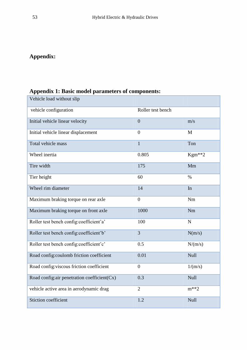
Appendix 1: Basic model parameters of components:
Vehicle load without slip
vehicle configuration Roller test bench
Initial vehicle linear velocity 0 m/s
Initial vehicle linear displacement 0 M
Total vehicle mass 1 Ton
Wheel inertia 0.805 Kgm**2
Tire width 175 Mm
Tier height 60 %
Wheel rim diameter 14 In
Maximum braking torque on rear axle 0 Nm
Maximum braking torque on front axle 1000 Nm
Roller test bench config:coefficient’a’ 100 N
Roller test bench config:coefficient’b’ 3 N(m/s)
Roller test bench config:coefficient’c’ 0.5 N/(m/s)
Road config:coulomb friction coefficient 0.01 Null
Road config:viscous friction coefficient 0 1/(m/s)
Road config:air penetration coefficient(Cx) 0.3 Null
vehicle active area in aerodynamic drag 2 m**2
Stiction coefficient 1.2 Null

54 Hybrid Electric & Hydraulic Drives
Internal combustion Engine Specifications
Input data out of range extrapolation
Engine type Spark ignition
Number of strokes 4
Swept volume 1.8 l
Fuel specific heating value 42700 KJ/Kg
Stoechiometric air/fuel ratio 14.4 null
BMEP dynamic 0 bar
CO emission for hot/cold engine at idle speed 70 g/h
HC emission for hot/cold engine at idle speed 20 g/h
NO x emission for hot/cold engine at idle speed 0.7 g/h
Particulate emissions for cold engine at idle speed 0 g/h
Low threshold for engine temperature 20 Deg c
High threshold for engine temperature 80 Deg c
Fuel specific heating value 42700 KJ/KG
Exhaust gas temperature at idle 250 Deg c
Number of combustion mode 1
Low threshold for engine temperature 20 Deg c
High threshold for engine temperature 80 Deg c
Engine speed for hot engine at idle speed 700 rpm
Exhaust gas temperature at idle 250 deg
Manual Gearbox:
Primary shaft rotary velocity 800 Rev/min
55 Hybrid Electric & Hydraulic Drives
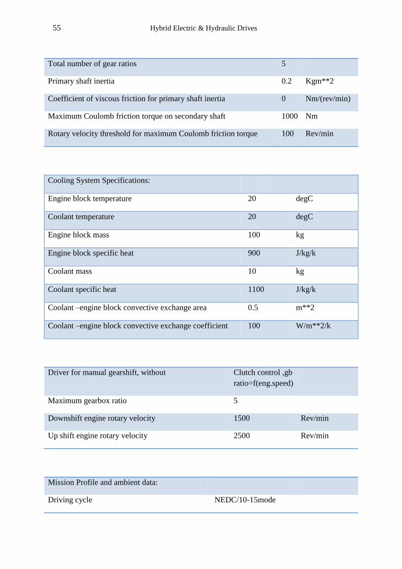
Total number of gear ratios 5
Primary shaft inertia 0.2 Kgm**2
Coefficient of viscous friction for primary shaft inertia 0 Nm/(rev/min)
Maximum Coulomb friction torque on secondary shaft 1000 Nm
Rotary velocity threshold for maximum Coulomb friction torque 100 Rev/min
Cooling System Specifications:
Engine block temperature 20 degC
Coolant temperature 20 degC
Engine block mass 100 kg
Engine block specific heat 900 J/kg/k
Coolant mass 10 kg
Coolant specific heat 1100 J/kg/k
Coolant –engine block convective exchange area 0.5 m**2
Coolant –engine block convective exchange coefficient 100 W/m**2/k
Driver for manual gearshift, without Clutch control ,gb
ratio=f(eng.speed)
Maximum gearbox ratio 5
Downshift engine rotary velocity 1500 Rev/min
Up shift engine rotary velocity 2500 Rev/min
Mission Profile and ambient data:
Driving cycle NEDC/10-15mode
56 Hybrid Electric & Hydraulic Drives
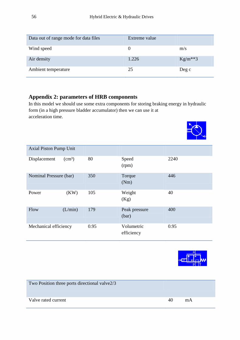
Data out of range mode for data files Extreme value
Wind speed 0 m/s
Air density 1.226 Kg/m**3
Ambient temperature 25 Deg c
Appendix 2: parameters of HRB components
In this model we should use some extra components for storing braking energy in hydraulic
form (in a high pressure bladder accumulator) then we can use it at
acceleration time.
Axial Piston Pump Unit
Displacement (cm³) 80 Speed
(rpm)
2240
Nominal Pressure (bar) 350 Torque
(Nm)
446
Power (KW) 105 Weight
(Kg)
40
Flow (L/min) 179 Peak pressure
(bar)
400
Mechanical efficiency 0.95 Volumetric
efficiency
0.95
Two Position three ports directional valve2/3
Valve rated current 40 mA

57 Hybrid Electric & Hydraulic Drives
Valve natural frequency 80 HZ
Valve damping ratio 0.8 null
Port P to A flow rate at maximum valve opening 10 l/min
Port P to A corresponding pressure drop 1 bar
Axial piston Motor
Motor displacement 100 Cc/rev
Typical speed 1800 Rev/min
Mechanical efficiency 97 %
Volumetric efficiency 97 %
Two position two ports directional valve (2/2)
Valve natural frequency 20 Hz
Valve damping ratio 1.8 null
Characteristic flow rate at maximum opening 1 l/min
Corresponding pressure drop 1 bar
Equivalent cross sectional area at maximum opening 5 mm**2
Maximum flow coefficient 0.7 null
Critical flow number 1000 null
58 Hybrid Electric & Hydraulic Drives
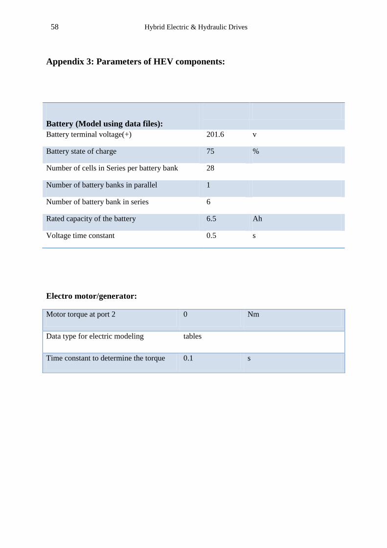
Appendix 3: Parameters of HEV components:
Electro motor/generator:
Battery (Model using data files):
Battery terminal voltage(+) 201.6 v
Battery state of charge 75 %
Number of cells in Series per battery bank 28
Number of battery banks in parallel 1
Number of battery bank in series 6
Rated capacity of the battery 6.5 Ah
Voltage time constant 0.5 s
Motor torque at port 2 0 Nm
Data type for electric modeling tables
Time constant to determine the torque 0.1 s
59 Hybrid Electric & Hydraulic Drives
References:
[1] Rydberg, K.E., (2009).Energy efficient hydraulic hybrid drives. The 11th
Scandinavian
International Conference on Fluid Power, SICFP’09, June 2-4, 2009, Linkoping, Sweden.
[2] Bosch Rexroth, 2008. Hydrostatic Regenerative Braking System HRB [online] (Update 23,
09, 2008) Available at:WWW.boschrexroth.com [23,09,2008], [05,12,2010]
[3] Nzisabira, J. & Louvigny, Y. & Duysinx, P., (2009). Comparison of Ultra Capacitors
Hydraulic Accumulators and Batteries Technologies to optimize Hybrid Vehicle
Ecoefficiency. Power engineering energy and electrical drives, Lisbon, March 18-20 2009,
Lisbon, Portugal.
[4] Toyota, 2010.Prius Brochure [online] (05, 12, 2010) available at: www.toyota.com/prius-
hybrid [Accessed 05 December 2010].
[5]DieselNet, 2000.Emission Test Cycles [online] (04, 2000) available at:
www.dieselnet.com/standard/cycles [Accessed 05 December 2010].
[6] Fielding, M. & Nota, R.2006. NEW VEHICLE TECHNOLOGY DELIVERS 30%
CARBON SAVING. Transport Statics of Great Britain, (30, MAY, 2008),
www.artemisip.com
[7] Machinery lubrication, 2009. Advice for Maintaining Hydraulic Accumulators [online]
(07, 2009) available at: http://www.machinerylubrication.com/Read/2305/hydraulic-
accumulators [Accessed 05 December 2010]
[8] Lin, T. & Wang, Q. & Hu, B. & Gon, W., 2009. Development of hybrid power hydraulic
construction machinery .Automation in construction, 19(1), pp.11-19.
[9] LMS, 2010. Product Manager-Thermal Management Solutions simulation of two phase
flow system with LMS Imagine lab Amesim [online] April 14th
2010. Available at:
www.lmsintl.com [Accessed 05 December 2010].
[10] Parker, 2009. Mobile Actuators and Accumulators Hydraulic Accumulators Catalog
HY10 Parker Hannifin corporation Hydraulic Accumulator Division [online] (2003)available
at : WWW.PARKER.COM [Accessed 05 11 2010].
60 Hybrid Electric & Hydraulic Drives
[11] U.S Department of Energy Efficiency and Renewable Energy, 2009.Featuring the Toyota
Prius [online] (2009) available at: www.fueleconomy.gov [Accessed 05 11 2010]
[12] The Clean Green Car Company, 2010. Toyota Prius Technical Information drives train
components [online] (2010) available at: www.cleangreencar.co.nz [2010].
[13] Hybrid Vehicle org, 2010.The first hybrid vehicle by Dr Ferdinand Porsche [online]
(2010) available at: www.Hybrid-vehicle.org [2010].
[14] Hybrid cars, 2010. 100th Anniversary of First US Hybrid Car Patent [online](March 01
2009) available at: www.hybridcars.com[2009]
[15]John1701a, 2008. Prius How It Works Multi Display [online] (09-13-2010) available at:
www.John1701a.com [2010]
[16] Engineering and Science, 2004.Godfather of the hybrid [online] (2004) available at:
www.eands.calthech.edu (volume Lxv11, number 3).
[17]Hybrid Synergy Drive-Toyota Information Terminal, 2009.technology hybrid [online]
(2009) available at: www.hybridsynergydrive.com[2009]
[18]TODAY/TOMORROW, JULY 2ND
2009.Recharge reuse Recycle, [online] (2009)
available at: blog.toyota.co.uk, Darryl McCarthy
[19]Consumer Guide Automotive, 2010.Hybrid Battery: None the Worse for Wear?,
[online](2010) by Rick Cotta- available at: consumerguideauto.howstuffworks.com [2010].
[20] Serbanescu,V.,Abaitancei,H.,Radu,G.A.,Radu,S.,(October 2009).Constructive influences
of the energy recovery system in the vehicle dampers.1st International Conference on
Innovations, Recent Trends and Challenges In Mechatronics,Mechanical Engineering and
New High-Tech Products Development.Bucharest,2009,Bucharest,Romania.