hybrid cpu-gpu distributed framework for large scale ... · hybrid cpu-gpu distributed framework...
TRANSCRIPT
EURECOMDepartment of communications mobiles
Campus Sophia Tech450 route des Chappes
B.P. 19306410 BiotFRANCE
Research Report RR-12-268
Hybrid CPU-GPU Distributed Framework for Large ScaleMobile Networks Simulation
June 5th, 2012Last update January 7th, 2013
Ben Romdhanne Bilel, Nikaein Navid ,Mohamed Said Mosli Bouksiaa , andChristian Bonnet
1EURECOM’s research is partially supported by its industrial members: BMW Group, Cisco,Monaco Telecom, Orange, SAP, SFR, STEricsson, Swisscom, Symantec.
i

Tel : (+33) 4 93 00 81 00Fax : (+33) 4 93 00 82 00
Email : {benromdh,nikaeinn,mosli,bonnet}@eurecom.fr

Hybrid CPU-GPU Distributed Framework for Large ScaleMobile Networks Simulation
Ben Romdhanne Bilel, Nikaein Navid ,Mohamed Said Mosli Bouksiaa , andChristian Bonnet
AbstractMost of the existing packet-level simulation tools are designed to per-
form experiments modeling a small to medium scale networks.The mainreason of this limitation is the amount of available computation power andmemory in quasi mono-process simulation environment. To enable efficientpacket-level simulation for large scale scenario, we introduce a new CPU-GPU co-simulation framework where synchronization and experiment de-sign are performed on CPU and node’s processes are executed in parallel onGPU according to the master/worker model [13]. The framework is devel-oped using Compute-Unified Device Architecture (CUDA) and denoted asCunetsim [18], CUDA network simulator. To study the performance gainwhen GPU is used, we also introduce the CPU-legacy version ofCunetsimoptimized for multi-core architecture.
In this work, we present Cunetsim architecture, design concept, and fea-tures. We evaluate the performance of Cunetsim (both versions) compared toSinalgo and NS-3 using benchmark scenarios [20]. Evaluation results showthat Cunetsim execution time remains stable and that it achieves significantlylower computation time than CPU-based simulators for both static and mo-bile networks with no degradation in the accuracy of the results. We alsostudy the impact of the hardware configuration on the performance gain andthe simulation correctness.
Cunetsim presents a proof of concept, demonstrating the feasibility of afully GPU-based simulation rather than GPU-offloading or partial accelera-tion, through adequate architecture.
Index Terms
Large Scale; Hybrid simulation; GPGPU; CUDA; Parallel simulation;


Contents
1 Introduction 1
2 The Cunetsim Framework 22.1 The Worker Design . . . . . . . . . . . . . . . . . . . . . . . . . 3
2.1.1 Applications (APP) . . . . . . . . . . . . . . . . . . . . . 32.1.2 Protocol stack(PROTO) . . . . . . . . . . . . . . . . . . 42.1.3 Mobility (MOB) . . . . . . . . . . . . . . . . . . . . . . 42.1.4 Connectivity (CON) . . . . . . . . . . . . . . . . . . . . 42.1.5 Packets services (PKT) . . . . . . . . . . . . . . . . . . . 5
2.2 The Master Design . . . . . . . . . . . . . . . . . . . . . . . . . 62.2.1 Hybrid Events Scheduler . . . . . . . . . . . . . . . . . . 62.2.2 Data Abstraction Layer . . . . . . . . . . . . . . . . . . . 72.2.3 Scenario Management . . . . . . . . . . . . . . . . . . . 8
2.3 Common APIs . . . . . . . . . . . . . . . . . . . . . . . . . . . 82.3.1 The Tester API . . . . . . . . . . . . . . . . . . . . . . . 9
2.4 Hardware Mapping . . . . . . . . . . . . . . . . . . . . . . . . . 92.4.1 Fully GPU version . . . . . . . . . . . . . . . . . . . . . 92.4.2 CPU-legacy version . . . . . . . . . . . . . . . . . . . . 10
3 Comparative Performances Results 103.1 Simulation runtime . . . . . . . . . . . . . . . . . . . . . . . . . 12
3.1.1 Static Scenario . . . . . . . . . . . . . . . . . . . . . . . 123.1.2 Mobile Scenario . . . . . . . . . . . . . . . . . . . . . . 14
3.2 Memory usage . . . . . . . . . . . . . . . . . . . . . . . . . . . 15
4 Hardware impact 164.1 GPU Impact . . . . . . . . . . . . . . . . . . . . . . . . . . . . . 16
4.1.1 Impact of total number of GPU cores . . . . . . . . . . . 164.1.2 Impact of GPU frequency . . . . . . . . . . . . . . . . . 16
4.2 CPU impact . . . . . . . . . . . . . . . . . . . . . . . . . . . . . 174.2.1 fully GPU . . . . . . . . . . . . . . . . . . . . . . . . . 174.2.2 CPU-legacy version . . . . . . . . . . . . . . . . . . . . 17
5 Discussion 19
6 Conclusion 19
v

List of Figures
1 Cunetsim Framework Architecture and Dependency . . . . . . . . 32 MOB WP functioning . . . . . . . . . . . . . . . . . . . . . . . . 43 Scheduling Ambiguities . . . . . . . . . . . . . . . . . . . . . . . 74 Cunetsim Hardware Mapping . . . . . . . . . . . . . . . . . . . . 95 Simple Grid Topology . . . . . . . . . . . . . . . . . . . . . . . 116 End-to-End Packet Loss: Under the same conditions, all simulators
present equivalent E-TO-E loss, considered as the output . . . . . 127 Simulation runtime of the static network: CPU simulators are effi-
cient on small scale but computing power becomes critical on largescale . . . . . . . . . . . . . . . . . . . . . . . . . . . . . . . . . 12
8 Simulation runtime of the mobile network: the complexity of wire-less mobile scenario highlights the limitation of classic approachesunder large scale conditions . . . . . . . . . . . . . . . . . . . . . 14
9 Memory usage vs. Drop probability . . . . . . . . . . . . . . . . 1510 Simulation runtime of different devices: Naturally, more cores means
higher efficiency . . . . . . . . . . . . . . . . . . . . . . . . . . 1611 Harware impact for Fully GPU version: neither the CPU frequency
nor the number of CPU-embedded cores has a significant impact . 1712 CPU Cores’ impact (Legacy): best performance was reached when
then number of thread is equal to the number of cores . . . . . . . 1813 CPU frequency impact (Legacy): As expected, the runtime is lin-
early related to the CPU frequency . . . . . . . . . . . . . . . . . 18
vi

1 Introduction
Packet-level simulators are usually based on a discrete event paradigm wheresequences of events are generated. In general, such events represent mobility, con-nectivity, channel calculation and in/out packets processing. The time complexityand memory usage of a simulation are then proportional to the frequency of theseevents for the total number of nodes, which represent the main bottleneckswhentargeting scalability and efficiency. There exists also a trade-off betweenthe ac-curacy of the models, in particular channel models, and time complexity that hasto be taken into account when targeting large scale simulations. This calls for aparallel node execution environment with minimal inter-processes communicationoverhead [9].
In the literature, there are three major approaches to deal with large scale sim-ulation: (i) CPU-based parallel & distributed simulation, (ii) Partial accelerationusing specific Co-processor and (iii) The fully GPU approach.
In a CPU-based parallel and distributed simulation [14], the platform may befederated and includes multiple copies of the same or different simulators (mod-eling different portions of the network) linked together either sequentially or inparallel. Such a federated approach makes use of the existing models and providesa rapid parallelization of existing sequential simulators [17]. However, such ap-proach introduces a significant overhead due to the synchronization among differ-ent processes and/or machines and requires sophisticated and expensive simulationinfrastructure [13]. This overhead may increase drastically in mobile environmentif the network topology and machines mapping is not dynamically managed (e.g.through nodes migration). For the majority of CPU-based simulators, the perfor-mance degradation happens when a combination of the limiting factors, mobilityrate, number of nodes, and traffic load increases. For the distributed simulators,such performance degradation happens when the inter-machines communicationincreases. A scalability demonstration, based on the distributed NS-3 has carefullyavoided the problem of the interaction between nodes in different simulation ma-chines [11]. Even if parallel and distributed simulators have crossed a scalabilityboundary, they introduce new problems such as the cost of a simulated node, thestrategy of initial nodes distribution and their migration across different machines.
The second approach addresses the question differently, It aims to increasethe efficiency of the simulation locally by offloading the most CPU-intensive partof the simulation from the CPU to a dedicated co-processor. The FPGA waswidely used as an acceleration solution [8] however, in some recent approaches,the Graphics Processing Unit (GPU) is used to offload intensive computingtaskssuch as channel modeling [5] and queuing [15] within the simulator. Recentstud-ies of GPUs allow us to utilize the GPU for more general-purpose computation(GPGPU) [16], or even as a GPU-accelerated simulation architecture when ac-curacy and runtime performance are both critical [4]. Thus, the GPU hasbe-come an increasingly attractive alternative to the expensive CPU-based parallelism,with significant computational power at a relatively low cost. With the advent of
1

the GeForce 8 series GPU in 2006 and the compute unified device architecture(CUDA) [12], the control of the unified stream processors of GPU is transparent tothe programmer, and CUDA provides an efficient and wealthy environmentto de-velop parallel codes in a high-level language without the need for graphics-specificknowledge. Even if this approach reduces significantly the computing time, thesimulation remains principally in the CPU which continues to be the main systembottleneck in large scale scenarios. Further, a continuous transfer between the GPUmemory and the CPU one presents a serious limitation of such approach.
The third approach aims to realize the simulation entirely on the GPU whichreduce significantly the memory transfer compared to the second approachanddecrease the synchronization latency compared to classic parallel approach. How-ever, the GPU is not fully X86 compliant and did not support CPU features, needsa specific software architecture to disclose its power and did not supportmemorylock mechanism. Because of these limitations, the fully GPU simulation approachis poorly studied even if it is extremely promising in term of raw performance.As a proof of concept, we propose to use the GPU as a main simulation environ-ment and the CPU as a controller, introduced VIA a new CPU-GPU co-simulationframework denoted as Cunetsim, CUDA Network Simulator. Cunetsim is an ex-perimental simulation platform allowing validation and experimentation of a novelapproach. As opposed to previous works, Cunetsim is designed to provide an inde-pendent parallel execution environment for each simulated node. Nodescommu-nicate with each other only through the message passing based on the buffer ex-change, thus avoiding the usage of any global knowledge on one hand,and increasesignificantly the parallelism level on the the other hand. Furthermore, it exploitsthe master/worker model for CPU-GPU co-simulation and provides hybrid syn-chronization model which maximizes the efficiency and respects the correctness ofthe simulation. The simulation exploits the large number of computing cores ofthe GPU to execute nodes in parallel and the high speed memory access to reducenodes communication latency.
The remainder of the paper is organized as follows. Section 2 presents theframework architecture and features. Preliminary comparative results are given insection 3. Detailed study of the hardware configuration impact is summarized insection4 and we discuss limits of our concept in section 5 followed by concludingremarks and future directions in section 6.
2 The Cunetsim Framework
Cunetsim framework is designed and implemented following a hardware/ soft-ware co-design approach to maximize the efficiency. The simulation distributionisbased on the master/ worker model [13] where the master controls the simulationachieved by the workers group. Figure. 1 summarizes the cunetsim components’hierarchy through three blocks: the master, the worker and common APIs.
2

Figure 1: Cunetsim Framework Architecture and Dependency
Conceptually, a worker is associated with one node and is therefore composedof a node’s five Worker Processes (WPs) [6]: (i) the application, (ii) the proto-col stack, (iii) the mobility, (iv) the connectivity and (v) the packet services.Theirfunctioning is explained in section 2.1. The master is also composed of five com-ponents: (i) The hybrid events scheduler, (ii) The data abstraction layer, (iii) Thescenario manager, (iv) The monitoring component and (v) The helper . The de-tailed implementation is explained in section 2.2. Common APIs regroup thoseshared by the master and workers. It includes three components: (i) system API,including CUDA APIs and libraries, (ii) monitoring API, and (iii) testing API.
2.1 The Worker Design
The Worker implements the simulated node, modeled as a stack of independentWPs. Nodes communicate through messages passing. Only buffers are exchangedbetween nodes to avoid global knowledge. In Cunetsim, each node contains fiveordered WPs described in the following sections.
2.1.1 Applications (APP)
Cunetsim provides a packet-level traffic generator to simulate application databased on packet size and inter-departure time. Each instance is completely inde-pendent, allowing the framework to support an important load. The traffic gener-ator tags the packet as a function of communication type: unicast, multicast andbroadcast, and assumes that such traffic will be processed by the PROTO and PKTWPs.
3
2.1.2 Protocol stack(PROTO)
implements the node behavior both in control and data planes, which are pro-tocol or algorithm specific. It may also include additional models required bysucha protocol. Cunetsim implements various broadcasting techniques, such as prob-abilistic, counter-based and location-based. Such implementations supportGPUparallelism and provide inter-process communication through a buffer exchange,avoiding simulation global knowledge, to ensure the simulation scalability and ef-ficiency.
2.1.3 Mobility (MOB)
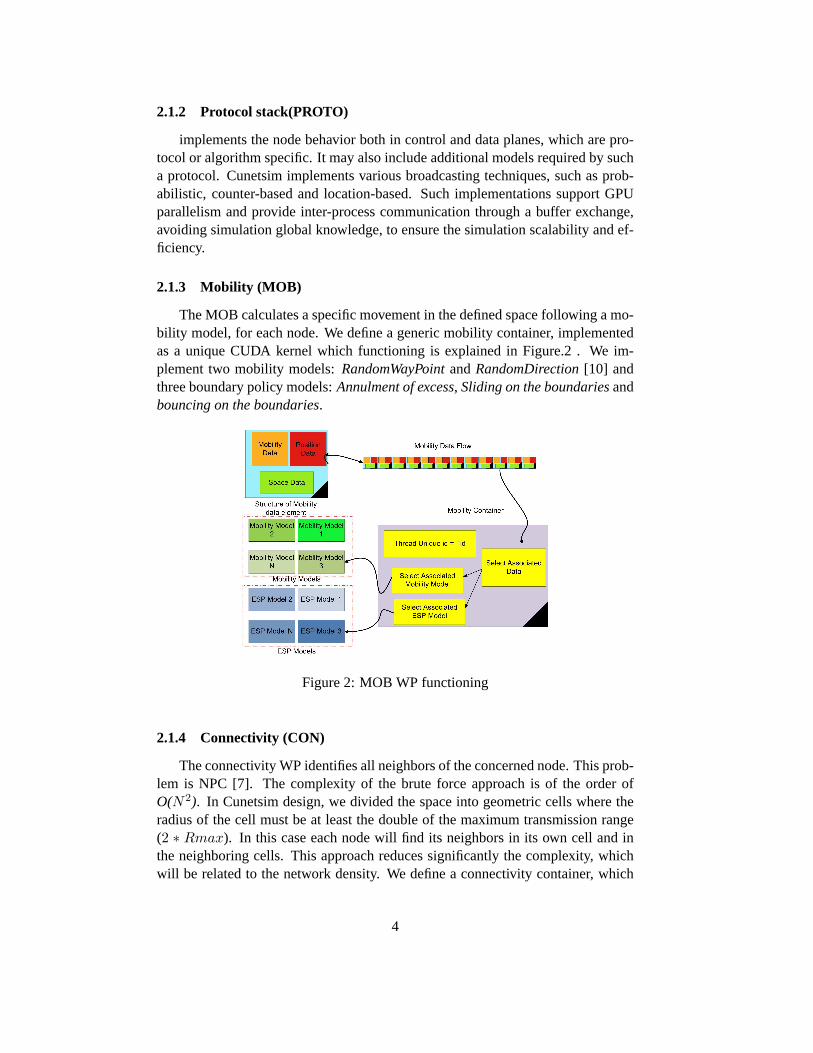
The MOB calculates a specific movement in the defined space following a mo-bility model, for each node. We define a generic mobility container, implementedas a unique CUDA kernel which functioning is explained in Figure.2 . We im-plement two mobility models:RandomWayPoint andRandomDirection [10] andthree boundary policy models:Annulment of excess, Sliding on the boundaries andbouncing on the boundaries.
Figure 2: MOB WP functioning
2.1.4 Connectivity (CON)
The connectivity WP identifies all neighbors of the concerned node. Thisprob-lem is NPC [7]. The complexity of the brute force approach is of the order ofO(N2). In Cunetsim design, we divided the space into geometric cells where theradius of the cell must be at least the double of the maximum transmission range(2 ∗ Rmax). In this case each node will find its neighbors in its own cell and inthe neighboring cells. This approach reduces significantly the complexity, whichwill be related to the network density. We define a connectivity container, which
4
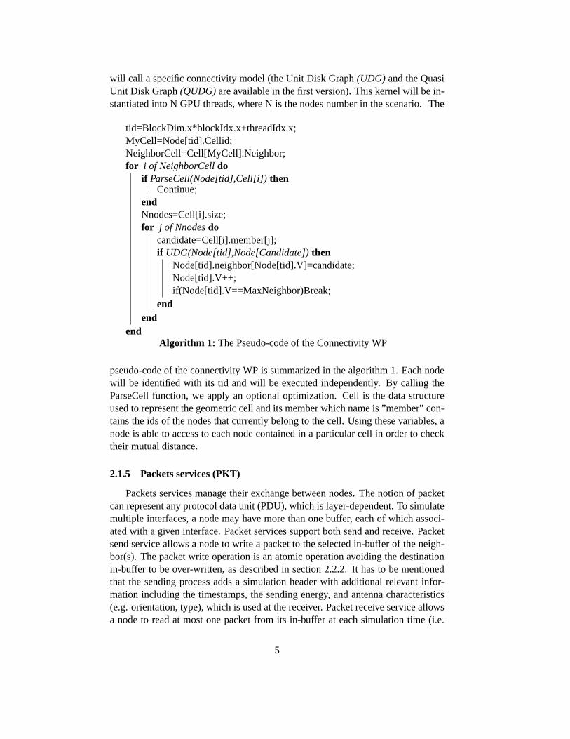
will call a specific connectivity model (the Unit Disk Graph(UDG) and the QuasiUnit Disk Graph(QUDG) are available in the first version). This kernel will be in-stantiated into N GPU threads, where N is the nodes number in the scenario. The
tid=BlockDim.x*blockIdx.x+threadIdx.x;MyCell=Node[tid].Cellid;NeighborCell=Cell[MyCell].Neighbor;for i of NeighborCell do
if ParseCell(Node[tid],Cell[i]) thenContinue;
endNnodes=Cell[i].size;for j of Nnodes do
candidate=Cell[i].member[j];if UDG(Node[tid],Node[Candidate]) then
Node[tid].neighbor[Node[tid].V]=candidate;Node[tid].V++;if(Node[tid].V==MaxNeighbor)Break;
endend
endAlgorithm 1: The Pseudo-code of the Connectivity WP
pseudo-code of the connectivity WP is summarized in the algorithm 1. Each nodewill be identified with its tid and will be executed independently. By calling theParseCell function, we apply an optional optimization. Cell is the data structureused to represent the geometric cell and its member which name is ”member” con-tains the ids of the nodes that currently belong to the cell. Using these variables, anode is able to access to each node contained in a particular cell in order to checktheir mutual distance.
2.1.5 Packets services (PKT)
Packets services manage their exchange between nodes. The notion of packetcan represent any protocol data unit (PDU), which is layer-dependent. To simulatemultiple interfaces, a node may have more than one buffer, each of which associ-ated with a given interface. Packet services support both send and receive. Packetsend service allows a node to write a packet to the selected in-buffer of theneigh-bor(s). The packet write operation is an atomic operation avoiding the destinationin-buffer to be over-written, as described in section 2.2.2. It has to be mentionedthat the sending process adds a simulation header with additional relevant infor-mation including the timestamps, the sending energy, and antenna characteristics(e.g. orientation, type), which is used at the receiver. Packet receive service allowsa node to read at most one packet from its in-buffer at each simulation time (i.e.
5
round). However, the in-buffer is capable of receiving up to M packets from othernodes at each round. The receiving service determines which messagehas to beread by the node based on the lowest timestamps and/or signal energy derived fromthe simulation header.
2.2 The Master Design
The master ensures the simulation correctness, simplifies the framework us-ability by providing high-level simulation APIs, and guarantees the simulation re-producibility. These features are performed via five components detailed below:
2.2.1 Hybrid Events Scheduler
Cunetsim events scheduler (CES) implements a conservative approach for alldependent WPs where we respect a strict order between sequential WPs for eachnode. This model was developed in [19] where the notion ofWP Pool is introduced:a WP pool,Πi is defined incorporating same WPj for all nodes. For a givenΠi,all Pij processes must end to assert thatΠ is achieved. This presents a simple yetefficient implementation of the coherence and consistency paradigm.In addition,CES addresses two fundamental scheduling issues: independent WPs on one handand the events sequencing of each WP on the other hand.
(1) Independent WPs concerns typically heterogeneous simulation and hap-pens when nodes are composed of different WPs sequences. Figure. 3(a) showsa situation where we have two kinds of nodes which implement two independentWPs: WP2 and WP5. In such case, conservative approach did not define a deter-ministic order between WP2 and WP5 pools. As Cunetsim targets to maximize theefficiency, in such situation we use an optimistic approach, where both of WP2 andWP5 pools can be executed in parallel on the GPU.
(2) The sequencing of WP’s events typically happens when the number ofcoresis not a multiple of the number of nodes. Figure. 3(b) shows one WP composedof 2 events for 3 nodes and 2 cores. In this figure each event is identified bya triple (WPid, Event id, Nodeid). In conservative and optimistic approaches,the execution of the event (1,2,1) at the same time as (1,1,3) is forbidden sinceastrict order exists. However respecting this order may induce a significant waste ofresources (e.g. 25%in this example), while executing both of them at the sametimewill not impact the correctness of the simulation. In such case, Cunetsim applies arelaxed approach within the events of each WP’s pool. In this way, the WPsorderand the events sequencing of each node will be preserved, thus maximizingtotalresource usage.
To summarize, the Cunetsim hybrid event scheduler works as following: Theconservative approach is used for sequential WPs as defined by the simulationmodel. The optimistic approach is applied when possible, especially for indepen-dent WPs and independent WPs sequences. Relaxed approach is applied for eventscheduling into each WP.
6

(a) WPs dependency: while the schedulercan determine that WP3 threads cannot startuntil finishing those of WP2 and WP5, thereis no strict order between them.
(b) Events Conflict: E113 and E121 willbe executed at the same time while thestrict synchronization prohibited
Figure 3: Scheduling Ambiguities
It has to be mentioned that the CES benefits from the GPU hardware schedulingcapabilities. Indeed, the optimistic approach is achieved using the GigaThreadsscheduler (i.e. GPU hardware acceleration), the relaxed approach using the 4 wrapschedulers of each SM. The conservative approach is implemented in software.
2.2.2 Data Abstraction Layer
Cunetsim data are modeled based on the kernel/flow model. We define sev-eral flows where each one presents a specific part of the simulation data.Data isgrouped by functionality. Each WP uses one (or more) flow and each node has aspecific box with R/W rights. One node can access foreign data with read right.Flow model is natively used by graphics application to manage the communicationbetween the GPU and the CPU. We apply a flows loading-offloading mechanismbetween the GPU memory (limited and non-extensible) and the principal memory(larger and extensible). The master manages flows transfer between the principalmemory and the GPU one, such that no WPs will be in famine situation.
The memory management component provides two services: memory alloca-tion abstraction (MAA) and critical section management (CSM). MAA insuresthedouble allocation of each data flow in both of the RAM and the DRAM. The syn-chronization of the two copies of the flow is a manual operation which must bespecified by the user. Critical section is a recurrent challenge in case ofsharedmemory between several processes. Software mutual exclusion solutionssuch assemaphores, mutex and locks are commonly used in CPU context. However, GPUcontext did not provide such explicit solutions. The problem arises mainly whentwo nodes try at the same time to write messages in a third node’s inbuffer, inwhich case we may lose some of them. CSM provides an abstraction of this prob-lem based on CUDA atomic operations: thanks to atomicInc, a node makes anatomic reservation operation before proceeding to the writing of the message. Thisoperation consists in atomically incrementing the writeindex, a pointer to a box inthe receiver’s buffer.
7

2.2.3 Scenario Management
This component ensures the reproducibility of the simulation via a completeXML layout incorporating five sub-categories: the system, the environment, thenetwork topology, the application configuration and the simulation I/O. This con-cept aims to simplify the interaction between the simulation and the user. Theprocess applied for cunetsim reflects the same experimentation workflow proposedon [6].
2.3 Common APIs
Common APIs are those shared by the master and the worker and include sys-tem/host, Cuda, monitoring and testing tool APIs and libraries. Cuda API includesthe driver and the runtime used to manage the GPU using high level programminglanguage such as C/C++. Cuda libraries provide an efficient hardwareaccelerationof common libraries such as Math and BLAS libs. The monitoring process is aCPU-expensive task which may reduce the efficiency of the simulation and intro-duce an important overhead. Since Cunetsim benefits from at least two computingcontexts, it could easily offload this process from one simulation context to anotherdepending on the load (e.g. from CPU to GPU or vice versa, or even fromone GPUto another). Cunetsim monitoring provides three APIs as follows:
GPU Monitoring: Each WP uses, in addition to simulation data flows, moni-toring data flows, where WP instances write their monitoring results (e.g. numberof messages, processing time, flags). A specific monitoring WP is implementedand used to process these flows to produce final results. In this approach, themonitoring process is included in the simulation and thus necessarily impacts itsperformances, however, the impact can be reduced using dedicated device (sec-ond GPU). Such approach is appropriate to online monitoring techniques since itprovides results as soon as they exist.
CPU Monitoring: The monitoring process dumps -in asynchronous mode- thesimulation data flows into the RAM to process them and produces final monitoringresults. The asynchronous dumping operation will not impact the simulation per-formance, however, the CPU process must be able to consume these flowsin thesame speed (or higher) that the simulation produces; otherwise the RAM will besaturated. This approach is more appropriate to offline monitoring techniquesinceit can use saved data.
Co-GPU-CPU Monitoring: In this approach, the monitoring process is sharedbetween GPU and CPU. As in the GPU approach, WPs use monitoring data flowsto write raw information, and as in the CPU approach, the CPU process dumpsin asynchronous mode the monitoring flows. This approach impacts moderatelythe simulation performance but reduces significantly the size of transferred data,making this approach more adequate for a large scale scenario for both offline andonline monitoring.
8

2.3.1 The Tester API
The tester API implements a validation component which ensures the simu-lation correctness, in particular the user-specific implementation for a givenWPand its integration with the simulation framework. The basic test consists of im-plementing the same algorithms, sequentially and in parallel, for both master andworker. The master tests the process, compares both of their results and validatesthe worker group results. It has to be noted that the testing process is onlyused indeveloping and debugging mode when the simulation correctness is required.
2.4 Hardware Mapping
In this section, we detailed the hardware mapping of the cunetsim’s softwarecomponents: First we present the hardware mapping of the fully GPU version andsecond we describe the CPU-legacy one.
2.4.1 Fully GPU version
Figure 4: Cunetsim Hardware Mapping
The hardware mapping of the software components is presented in Figure.4,further detailing the CPU-GPU co-simulation. At each time, it can be seen thateach WP is mapped to a GPU core, called scalar processor (SP) wrappedwithina streaming multiprocessor (SM), while the master processes are mapped to CPUcores. Nodes’ WPs exploit three memory levels: registers, shared and global mem-ory. Registers include local variables of each WP instance. Shared memory isused as an acceleration cache where a prior knowledge on the data is available.Global memory is used when WPs communicate (sending messages / reading po-sition) without having a prior knowledge on communicating nodes. It has to be
9

mentioned that such mapping provides a dedicated execution environment for eachnode, where inter-WP and node communication is minimized over three memorystages. As for the Master, it is represented by two processes: (i) the simulation coreand the Data abstraction layer representing the primary process of the master, and(ii) monitoring process in charge of data collection and user interface represent-ing the secondary process of the master. This separation maintains a strict priorityorder between the primary and the secondary process.
2.4.2 CPU-legacy version
Cunetsim architecture is designed for a fully GPU simulation as detailed in sec-tion 2.4.1. However the GPGPU is a recent discipline and rare are the data-centerswhich use the GPUs as computing Co-Processors. On the other hand, Current andfuture CPUs are also multi-core and provide interesting features, as the vector par-allelism. These reasons have convinced us to provide a pure CPU solution.Basedon the PGI unified Binary technology [3], we generate a CPU compliant versionwhich parallelizes nodes through the OpenMP API using several threads. The usercan specify the number of threads in conformity with the CPU capabilities. Wenote that the software architecture and code did not change, only the compilationprocedure is different. in following, this version will be appointed as Cunetsim-LN,where the last number presents the threads’ number.
3 Comparative Performances Results
To evaluate the real performance of each approach presented in section 1 underlarge scale condition regardless of different models impact, we extend the bench-marking methodology for network simulators presented on [20] to support wire-less and mobility conditions. In this methodology, authors implement identicalnode model for all considered simulators. They demonstrate that NS-3 [2], Jistand Omnet++ have the best performance. However, they did not address mobilityissues and ignored Sinalgo [1], known as a stable simulator on large scale condi-tions. In the following study, we choose Sinalgo as a representative CPU-basedsolution while NS-3 is involved as the most optimized public simulator, providingalso a stable distributed version over MPI. The CPU version of cunetsim, whichinvolves 4 CPU cores is a representative case of the partial acceleratedapproachwhile the GPU version presents the fully GPU approach. The mobility and theconnectivity algorithms are the same as we propose for all simulators. Only a sim-ple flooding protocol is implemented using equivalent algorithms. We proposetwobenchmark scenarios: The first compares the performance of each simulator’s ker-nel regardless of the efficiency of implemented models, while the second addressestheir robustness in mobile conditions. The first scenario models a simple network,where the nodes are arranged in a grid topology as illustrated in Figure. 5.It in-cludes one traffic source which generates600 uniform packets with1 second of
10

Figure 5: Simple Grid Topology
inter-departure time. Packet size is fixed to 128 Bytes. All nodes -includingthesource- relay unseen packets after a delay of1 second, thus flooding the totality ofthe network. The delay of1 second models the propagation. Nodes do not provideany packets management services. Transmission and reliability are modeled onthe channel using a fixed dropping probability which is identical on all links.Thesender is the node with the lowest identity and the receiver is the one with the high-est identity. In the second scenario, nodes are mobile. The mobility model is therandom way point with speed uniformly distributed between1− 5m/s. The max-imum transmission range, Rmax, is100 and the connectivity model is UDG. Thesimulation space is a cubic free space whose dimensions are1600 ∗ 1600 ∗ 200 m.Each node moves before each round and recalculates its connectivity set. Both ofthese scenarios are outlying real networks and include major node simplificationsnevertheless, they have two advantages: they guaranteed a relevant and neutralcomparative since they minimize the models’ efficiency impact and they provide arepresentative estimation of the computing power needed for such simulations.
All simulation runs were conducted using a simple PC including an INTEL i7940 CPU (4 cores with hyper-threading), 6GB of DDR3 and one GPU: theGeForce460 1GB (336 cores for GPGPU computing). 4 machines are used for the dis-tributed NS-3, interconnected VIA a Gigabyte switch. The OS is Ubuntu Linux11.10, the Java version is 1.6 and the Nvidia driver version is 285.05.33. Our mea-surements were taken using NS-3.13, Sinalgo 10.75.03 and Cunetsim prototype.To validate the model equality, we use the first scenario with all simulators wherewe varied the drop probabilities in the interval[0, 1]. Figure.6 depicts the end-to-end packet loss repossessed and normalized from different simulators, given thedropping probability and the network size. All studied simulators produce similarresults.We conclude that our implementations are equivalent -in terms of output- tothose of [20]. We evaluate simulators’ efficiency regarding two performance met-rics: simulation runtime and memory usage. Our results give the average of fiveexecutions. The minimal simulation time is set to700 seconds.
11

Figure 6: End-to-End Packet Loss: Under the same conditions, all simulatorspresent equivalent E-TO-E loss, considered as the output
3.1 Simulation runtime
To evaluate the simulation runtime of the concerned simulators, we fixed thedrop probability to0.1 and we increased the network size from4 to 102K nodes.Section 3.1.1 analyzes the first scenario results while the section 3.1.2 addressesthe second one.
3.1.1 Static Scenario
Figure 7: Simulation runtime of the static network: CPU simulators are efficienton small scale but computing power becomes critical on large scale
Figure. 7 shows the average simulation runtime for each simulator. For smallto medium networks, Cunetsim-L4 is the fastest simulator up to 2000 nodes and re-mains faster than Sinalgo and NS-3 in all cases. Beyond, Cunetsim (GPU) becomesthe most efficient simulator and the deviation is growing with the network size.Function of the simulators runtime, we distinguish four network size intervals:small networks [2-50], medium networks [50-200], large networks [200-2000] andthe very large networks [2000-102000].
12

For small scale Cunetsim-L4 and NS-3 are the most efficient simulators. Infact, much of NS-3 components use the very high-speed L3 cache compared withmuch slower RAM while the cunetsim-L4 uses also the L3 cache and all CPUcores. Cunetsim-GPU is outperformed for two reasons: first the impact ofdatatransfer between the RAM and the GDRAM is significant, second the GPU isunderused since only few cores are active. For medium scale, both versions ofcunetsim are faster than NS-3. In fact, when the network size increases, cunetsimuses additional GPU cores. However,the data transfer between the RAM and theGDRAM remains significant which allows Cunetsim-L4 to be the fastest solution.In both intervals, distributed NS-3 suffers from the initial setup load of the MPI,relegating it behind the classic version.
For large scale, sinalgo has successfully overcome NS-3 thanks to its optimizednodes management. However, the distributed version of NS-3 remains stableover-coming easily sinalgo. On the other hand, cunetsim-L4, reaches the CPU limitwhile Cunetsim-GPU remains stable in this interval. Finally, for 2000 nodes, bothof Cunetsim-GPU and Cunetsim-L4 need 0.35 second, 80 times faster than NS-3and 26 times faster than sinalgo. For very large scale, the power of cunetsim-GPUis revealed, the number of cores involved in the simulation makes the difference andCunetsim-L4 fails to follow, even if it remains the most efficient CPU-based simu-lator. For 48K nodes cunetsim needs 5.93 seconds, 3.5 times faster than cunetsim-L4, 22 times faster than sinalgo and 150 times faster than NS-3. It is interesting tocompare in such scale Cunetsim-4L and Distributed NS-3 since both use the samecomputing power in theory. In fact, Cunetsim-4L overcomes NS-3 due to two ma-jor reasons: first it uses a shared memory synchronization (over OpenMP) whileNS-3 uses Ethernet (over MPI). Second, The events scheduling is completely dif-ferent: Cunetsim has a prior knowledge regarding events relationship while NS-3has only their timestamps as a scheduling information.
From a theoretical point of view, if we suppose that a CUDA core is, as efficientas an i7 core, we can admit that at the same frequency, they are equivalent. Asour GPU includes224 effective CUDA cores @676Mhz and our CPU includes4cores @3.6Ghz(overckolecd+ turbo mode), than the maximum theoretical gain is9.46 which is two times higher than what we achieved. This value suggests thatthere still exist some interesting optimizations to consider, especially increasingthe GPU use which did not exceed 82% while Cunetsim-L4, NS-3 and sinalgosaturate the CPU. The SIMD architecture of the GPU implies that we dedicatedthe totality of each stream multiprocessor (SM)1 to 32 nodes until they finished. Insuch a situation we allocated resources for all nodes, including inactive ones whilea sequential execution (CPU) did not waste resources.
13

Figure 8: Simulation runtime of the mobile network: the complexity of wirelessmobile scenario highlights the limitation of classic approaches under large scaleconditions
3.1.2 Mobile Scenario
Figure. 8 shows the average measured simulation runtime for each simulator.The mobility imposes the evaluation of nodes connectivity in each round. Onceagain, the general behavior of the five simulators is similar to the previous sce-nario. NS-3 is the fastest CPU-based simulator up to36 nodes and cunetsim-L4becomes the fastest CPU-based simulator beyond. NS-3 runtime increasesexpo-nentially as a function of network size while Sinalgo and Cunetsim-L4 seem morerobust. The distributed version of NS-3 increases its leeway but did not influencethe global behavior. Thus, distributed NS-3 remains faster than sinalgo upto 800nodes but its computing time becomes unstable further. Cunetsim-L4 runtime re-mains relatively invariant for small to medium networks, and becomes a functionof nodes’ number nearby of 1000. Sinalgo presents a quasi-linear runtime as afunction of the network size but cannot achieve a very large scale simulation inrealistic time (simulating 48K nodes requires 3552 seconds).
Cunetsim(GPU version) runtime is linear per segment between4 and 8000nodes. For each segment the runtime is almost linear. From this threshold, itbecomes relative to the network size but remains reasonable, even for100K nodes.In all cases, Cunetsim is extremely faster than all CPU-based simulators. For48knodes cunetsim is up to9.2 times faster than Cunetsim-L4 and260 times fasterthan sinalgo. NS-3 is unable to compete in such scale. In addition the CPU-legacyversion presents very interesting results since it is28 times faster than Sinalgofor the same scale. As the results of the distributed NS-3 prove, distributing thesimulation over several machines is not sufficient in itself but must be coupled with,either a clever networking partitioning or a specific distributed event scheduler.
1Fermi architecture’ SMs include 32 Cuda cores
14

The higher performance of Cunetsim (in both modes) is due to the simulta-neous action of four factors.(i)The high parallelism degree of Cunetsim architec-ture allows efficient use of the GPU computing power and all CPU cores in theCPU-legacy mode. (ii)The connectivity algorithm was designed and optimizedtobe parallel and distributed taking advantage of the largest cores’ number. (iii)TheDRAM offers larger bandwidth than the current RAM, theoretically 10 times faster.(iv)The software scheduling task becomes a critical process in CPU context, whileits overhead is minimized in GPU since it is achieved using dedicated hardware.Since (iii) and (iv) are not available for the CPU-legacy version, the difference be-tween both versions runtime is growing function of the network size. For a verylarge network the GPU version is up to9.2 times faster than the CPU one whichproves the interest of using the GPU as a Co-processor.
3.2 Memory usage
Figure 9: Memory usage vs. Drop probability
Figure. 9 shows the maximum used memory during the simulation as a func-tion of the dropping probability for a fixed network size (3721). We note thatboth cunetsim versions use exactly the same quantity of RAM then we just men-tion cunetsim in this section. The drop probability affects the network traffic andthe number of exchanged messages. Sinalgo presents a slight decreaseof its usedmemory when the traffic decreases, while NS-3 presents a more flexible behaviorand adapts its usage to the network load. Cunetsim uses always the same mem-ory for a fixed network size because each simulated node has at least twofixedbuffers. Sinalgo needs between 20% and 600% more than NS-3 while Cunetsimseems more efficient for large traffic load. We notice, however, that NS-3 has adynamic memory management process while Cunetsim assigns a fixed buffer foreach node.
15

4 Hardware impact
The performance of cunetsim is directly related to the hardware efficiency,however, the GPU on one hand and the CPU on the other hand affect unequallythe simulation performance. This section provides a qualitative and quantitativestudy of their respective impacts as a function of the number of cores and the fre-quency. We note that we use the first scenario based on the grid topology(section3)since old devices did not support Curand library.
4.1 GPU Impact
4.1.1 Impact of total number of GPU cores
We propose to compare four devices which differ essentially by their numberof embedded cores: The 8400GS includes 8 Cuda cores. The FX880M isa mobileGPU including 48 Cuda cores. The GTX 560 includes 336 Cuda cores whiletheGTX 580 includes 512 one. We varied the network size from 4 to 246K, measuredthe simulation runtime with each of the four devices and reported the results inFigure. 10. For a small network [4,81], the GPU-CPU data transfer overhead isthe bottleneck. For a middle-range network [100, 250], the GPUs having the samearchitecture offer similar performance. As for networks involving more than 250nodes, both 8400GS and FX880M GPUs are overloaded by the computationchargeand their few cores (8, 48) are no longer able to compete with the GTX 560 and580 GPUs. The difference between the latter is proportional to their cores’ number.
Figure 10: Simulation runtime of different devices: Naturally, more cores meanshigher efficiency
4.1.2 Impact of GPU frequency
For this experiment, we use three devices (1: GTX460@715 Mhz, 2: GTX460@763 Mhz (reference) and 3: GTX560 @810 Mhz) where the major difference is
16

the GPU frequency. We fixed the network size to 246K nodes and we calculatedthe runtime of each device. Results are summarized in Figure. 11. The GTX 560is 7% faster than the reference device while its frequency exceeds by 6.15%. Thefirst device, is 7.5% slower than the reference one while its frequency is lower by6.71%. These measurements demonstrate that the runtime is proportional to thefrequency of the GPU, however, the frequency evolution is generally less signifi-cant and more expensive than the Cores’ number.
Figure 11: Harware impact for Fully GPU version: neither the CPU frequency northe number of CPU-embedded cores has a significant impact
4.2 CPU impact
To evaluate the CPU impact, we distinguish the two versions of cunetsim: Thefully-GPU version where the CPU manages the simulation and the CPU-legacyone where it achieves the totality of the simulation.
4.2.1 fully GPU
To evaluate the sensibility of the fully GPU version to the CPU capabilities,we fixed the network size to 246K nodes. First we vary the enabled CPU coresfrom 4 to 1. Second, we reduce its frequency gradually from 3.06 Ghz to1.6 Ghz.Results are reported on fig 11 where we can observe that the CPU impact isnotproportional to the CPU power:reducing the frequency by 45% implies only 5% ofperformance loss.
4.2.2 CPU-legacy version
We conduct 6 series of measurement where we varied the number of threadsinvolved in the simulation between 1 and 8. Our CPU is a i7-920 including fourcores with the hyper-threading technology. This means that each core is able to ex-ecute two threads. We varied the network size between4 and72k nodes. Figure.12
17

summarizes results. As expected, the Cunetsim-L1 runtime is generally the slow-est one, Cunetsim-L2 presents a gain of 23 % while the Cunetsim-L4 gain is about46%. When the number of active threads exceeds the number of physicalcores,we observe a relative performance degradation (about 4-5%), this phenomenon ismainly due to concurrence between threads which complicates the schedulingop-eration.
Figure 12: CPU Cores’ impact (Legacy): best performance was reached when thennumber of thread is equal to the number of cores
Based on these results, we conduct 4 series of measurement using the Cunetsim-L4 in the same conditions, where we varied the CPU frequency between 1.6Ghzand 3.6Ghz. Results are reported on Figure.13. We observe that the totalruntime isa function of the CPU frequency. In average, An increase of 30% on the frequency,implies an increase of 20% on the performance. These results demonstrate that thelegacy version depends on the CPU computing power and profits of the multi-corecapability.
Figure 13: CPU frequency impact (Legacy): As expected, the runtime is linearlyrelated to the CPU frequency
18

5 Discussion
In this section, we briefly discuss three limiting factors of Cunetsim, namelyevent scheduler, neighborhood discovering and floating point precision.
Event Scheduler The conservative approach that we use for WPs in Cunetsimevents scheduler presents an efficiency weakness for small network size. To reacha reasonable efficiency ratio, the network size must be greater than the number ofGPU cores. Note that current GPU includes up to1500 cores for mono-GPU de-vices. On the other hand, this approach can induce an important waste of resourcesin case of parallelization in CPU context where the number of cores is between 4and8 if we address a small network. However, in large scale scenarios, the differ-ence between this schedulers and an optimal one will be reduced.
Neighborhood discovering Cunetsim implements an optimized connectivity WPwhich aims to minimize the number of comparisons; the optimization is basedon the existence of Rmax. Whatever the wireless technology is, this approach isadapted to the free space model, but remains relevant for terrains which includeobstacles and multi-path channel. In this case, the correctness of the simulationwill be respected if these variations are taken into account for the calculation ofRmax value. It is worth noting that it remains possible to turn off this optimizationat the expense of the simulation runtime.
Floating Point Precision The implementation of the floating point on NVIDIAdevice is not fully IEEE compliant. To analyze the difference between a GPUand CPU implementation, we use the distance computing between two nodes as abenchmark test and calculate this distance using both, over 1 million of samples.The difference between each pair of results is less than 0.01%. Depending on thescenario, this difference might cause some simulation inaccuracy (e.g. channelmodeling).
6 Conclusion
New challenges emerge when simulating large scale mobile networks, espe-cially if we consider the paradigm ofvery large network rather thanthe network ofnetworks. While network simulation tools are widely used for validation and per-formance evaluation, their scalability and efficiency remain challenging. Cunet-sim aims to unlock the parallel capabilities of the state-of-the-art hardware andsoftware architectures to achieve simulation scalability and efficiency with signifi-cantly lower cost. Cunetsim is the first fully GPU based simulator which providesa CPU-GPU co-simulation framework for large scale scenarios. In contrast withexisting GPU acceleration approach, the simulation is fully executed over the GPU.
19

Further, Cunetsim proposes an efficient solution for the management of memorycritical section which presents a real challenge of the GPU programming model.
Performance results show that the execution time could be radically improvedwhen GPU parallelism is used to carry out the simulation. In particular, Cunetsimis able to achieve up to260 faster execution time than existing simulators, whentargeting large scale mobile networks. The results also reveal that the existingsimulators could be further improved through multi-core parallelism.
Acknowledgments
This paper describes work undertaken in the context of the LOLA and CONECTproject. The research leading to these results has received funding from the Euro-pean Community’s Seventh Framework Programme under grant agreementno248993andno57616.
References[1] http://disco.ethz.ch/projects/sinalgo/.
[2] http://www.nsnam.org/.
[3] http://www.pgroup.com/resources/unifiedbinary.htm/.
[4] P. Andelfinger, J. Mittag, and H. Hartenstein. Gpu-basedarchitectures and their benefit for accurate andefficient wireless network simulations. InMASCOTS, 2011 IEEE 19th International Symposium on, pages421–424. IEEE, 2011.
[5] S. Bai and D. Nicol. Acceleration of wireless channel simulation using gpus. InWireless Conference (EW),2010 European, pages 841–848. IEEE, 2010.
[6] B. Bilel, N. Navid, K. R., and B. C. Openairinterface large-scale wireless emulation platform and method-ology. InMSWIM. ACM, 2011.
[7] H. Breu and D. Kirkpatrick. Unit disk graph recognition is np-hard.Computational Geometry, 9(1):3–24,1998.
[8] E. Chung, E. Nurvitadhi, J. Hoe, B. Falsafi, and K. Mai. Protoflex: Fpga-accelerated hybrid functionalsimulator. InIPDPS 2007. IEEE International, pages 1–6. IEEE, 2007.
[9] R. Fujimoto, K. Perumalla, A. Park, H. Wu, M. Ammar, and G. Riley. Large-scale network simulation:how big? how fast? In11th IEEE/ACM MASCOTS 2003., pages 116 – 123, oct. 2003.
[10] J. Harri, F. Filali, and C. Bonnet. Mobility models for vehicular ad hoc networks: a survey and taxonomy.Communications Surveys & Tutorials, IEEE, 11(4):19–41, 2009.
[11] C. P. Ken Renard and J. Clarke. A performance and scalability evaluation of the ns-3 distributed scheduler.The Workshop on ns-3 (WNS3)), 2012.
[12] C. Nvidia. Compute unified device architecture programming guide.NVIDIA: Santa Clara, CA, 2011.
[13] A. Park and R. Fujimoto. Efficient master/worker paralleldiscrete event simulation.2009 ACMIEEESCS23rd Workshop on Principles of Advanced and Distributed Simulation, pages 145–152, 2009.
[14] A. Park and R. M. Fujimoto. Parallel discrete event simulation on desktop grid computing infrastructures.International Journal of Simulation and Process Modelling, 5(2):157 – 171, 2009.
[15] H. Park and P. A. Fishwick. An analysis of queuing network simulation using gpu-based hardware acceler-ation. ACM Trans. Model. Comput. Simul., 21(3), Feb. 2011.
[16] K. Perumalla. Discrete-event execution alternatives on general purpose graphical processing units (gpgpus).In Proceedings of the 20th Workshop on Principles of Advanced and Distributed Simulation, pages 74–81.IEEE Computer Society, 2006.
[17] K. Perumalla, R. Fujimoto, T. McLean, and G. Riley. Experiences applying parallel and interoperablenetwork simulation techniques in on-line simulations of military networks. pages 97–104, 2002.
20

[18] B. Romdhanne and B. Navid. Cunetsim: a new simulation framework for large scale mobile networks. InProceedings of the 5th International ICST Conference on Simulation Tools and Techniques, pages 217–219,2012.
[19] B. romdhanne Bilel and Navid. Cunetsim: A GPU based simulation testbed for large scale mobile networks.In The 2nd International Conference on Communications and Information Technology (ICCIT): WirelessCommunications and Signal Processing (ICCIT-2012 WCSP), pages 374–378, June 2012.
[20] E. Weingartner, H. Vom Lehn, and K. Wehrle. A performancecomparison of recent network simulators. InCommunications, 2009. ICC’09. IEEE International Conference on, pages 1–5. Ieee, 2009.
21