hwp-k series water sourced packaged air … sourced packaged air conditioners applications manual...
TRANSCRIPT

Water Cooled Air ConditionersApplications Manual
HWP-K UC8 Series
Page 2 of 20
Water Cooled Air ConditionersContents
HWP-K UC8 SERIESLocation & Acccess 3Noise Considerations 4Water Treatment for Systems using Cooling Towers
5
Water Loop & Unit Control 6Selection of Balancing Valves 8Heat Rejection Equipment Variations 10Initial Cleaning of System 12Water Balancing 13Pre Start-Up Checks 15Test Run 16Commissioning 17
Other Relevant Documents:
HWP 36–275 UC8 Technical Data
HWP-UC8 Installation & Maintenance
HWP Specification Sheets
(Available at www.temperzone.biz)
While this Applications Manual has been prepared and provided in good faith, Temperzone Ltd takes no responsibility for its
accuracy and reserves the right to make changes at any time.

Page 3 of 20
1. LOCATION & ACCESS
1.1 The co-ordination of various trades is essential in order to achieve maximum accessibility for the maintenance, servicing and possible removal of any air conditioner after it is installed. Ensure safe and reasonable access to :
- electrical access panels - fittings and valves at the water connections - air filter for removal - drain pan for cleaning. - EC motor driver (if fitted)
Temperzone recommends an access panel (either hinged or removable) be provided to enable a duct lifter or similar hoist to remove the unit from the ceiling space should repairs or replacement be deemed necessary. Failure to provide adequate acccess may compromise warranty repairs or replacement and costs involved.
1.2 Pipework, electrical cables and other obstructions must not prevent the unit from being totally removed, if necessary, at a later date.
1.3 Specify ceiling access panels under all ceiling space mounted units. The size and position of these access panels should allow for servicing of the unit as mentioned above.
1.4 Position each unit so that the principal sound emission is outside the most frequently occupied space, e.g. locate it over a hallway instead of a room.
1.5. Locate the units as close as possible to the shared foyer/corridor of each floor of the building to minimise the length and cost of water piping, and electrical conduit. This arrangement often provides more acceptable sound levels and easier maintenance.
1.6 For apartment and hotel buildings, mounting the unit inside a bathroom ceiling space is a good idea for both acoustic and access space reasons.
Water Cooled Air Conditioners Application

Page 4 of 20
2. NOISE CONSIDERATIONS
Temperzone Ltd has put its best efforts into designing a quiet unit, but these efforts can only be appreciated when the unit itself is properly installed and the unit is part of a good overall system’s design.
2.1 Ducts and Outlets 2.1.1 Ductsandoutletsshouldbecorrectlysized.Theactualsizesaredeterminedbytheairflow
volumerequirement.Generallythemainsupplyairductvelocityshouldbebelow4–6m/s. Anybranchductingshouldhaveavelocitybelow4m/s.
2.1.2 Donotlocateareturngrilleunderornearaunit.Placeitatleast1.5mawaytoreducenoisebreakout.Thereturnairgrilleshouldbesizedforlessthan2.5m/sairflow.
2.1.3 Whenpossible,separateturnsorfittingswithstraightductabout4or5ductdiameterslong. 2.1.4 Heatingorcoolingductworkandfittingsshouldbesealedagainstairloss. 2.1.5 Ductworkandfittingsforheatingorcoolingshouldbethermallyinsulatedwithinsulation
complyingwithlocalstandardsandNCCrecommendations.
2.2 Recommendations For Noise Isolation 2.2.1 Linetheductwithacousticinternalinsulationinnoisesensitivelocations. 2.2.2 Alwaysuseflexibleconnectionsbetweenunitandrigidducts. 2.2.3 Usevibrationisolatingmountsbetweenunitsandstructure. 2.2.4 Insoundcriticalareas,minimisedirectsoundradiationbyinstallinganacousticbarrierunder
theunit.Usedensematerialswithacoveringareaofabouttwicethesizeoftheunitfootprint. 2.2.5 Whereverpossible,separateductturnsorfittingswithstraightduct,about4or5ductdiameters
long.
2.3 Fan SpeedFor each unit, select the fan speed which gives the required air flow appropriate to the static pressure of the attached duct.
Water Cooled Air Conditioners Application

Page 5 of 20
3. WATER TREATMENT FOR SYSTEMS USING COOLING TOWERS
In an open cooling tower system, system water is exposed to contact with ambient air, exchanging heat and substances which commonly cause problems such as corrosion, scale formation, biological growths and suspended solid matter. Poor system performance will occur when scale builds up on the heat transfer surface inside the water cooled unit’s condenser pipework. Because of the reduced effectiveness of the condenser heat transfer surface, a seriously scaled condenser may cause the air conditioner to cut out in high pressure in the cooling mode or low temperature safety in the heating mode.
The complexity of water caused problems and their correction in cooling systems makes it important for the system’s designer to obtain the advice of a water treatment specialist as early as possible in the design stage and to follow the specialists advice regularly thereafter during design, construction and operation.
There has been a significant improvement in water treatment chemistry in recent years. Currently used chemical compounds include crystal modifiers and sequestering chemicals.
We recommend a professional water treatment and maintenance programme be adopted which meets local regulations (eg AS/NZS 3666 or AIRAH HVAC&R Maintenace Application Manual). Any Cooling Tower should be selected on the basis of the water quality to be used and water treatment required. Routine maintenance will help ensure optimal performance of the system.
Water Cooled Air Conditioners Application

Page 6 of 20
4. WATER LOOP & UNIT CONTROL
4.1 Water Loop Temperature Proper water loop temperature control is critical to the operation of a hydraulic system. Loop
temperatures outside the recommended range will severely impact equipment performance, energy usage and efficiency.
Min. water temp. Heat cycle at nominal flow 10°CMin. water temp. Cool cycle at nominal flow 15°CMin. water temp. Cool cycle with water regulating valve 5°CMax. EWT Heat cycle at nominal flow 30°CMax. EWT Cool cycle at nominal flow 50°C
Loop Temp. System Function < 5°C If a water regulating valve is fitted, the HWP unit’s system protections may stop the
compressor operation to prevent freeze up in the water loop. < 15°C If a water regulating valve is not fitted, the HWP unit’s system protections may stop the
compressor operation to prevent freeze up in the water loop. 15°C Run gas or electrical boiler or hot water heat pump to input heat into the water loop. 15 – 30°C System is within nominal operating range and no heat is required to be added or
rejected from the water loop. Run circulating pump only. > 30°C Start Cooling Tower water pump if this is a separate pump to the main circulating pump. > 32°C Start the Cooling Tower or dry cooler (radiator) fan(s).
4.2 Interlock Options for Pumps & Water Flow Verification Maintaining water flow is vitally important to water cooled cooling units and heat pumps, as a loss of
water flow will lead to nuisance fault trips and, in the case of heat pump versions, put the water side heat exchanger in danger of freezing up.
Each unit is fitted with a ‘UC8’ Unit Controller which provides internal protection for the unit and system, and also provides the opportunity to allow for the following: -4.2.1. No Water Flow Protection, i.e. Water Flow Verification. This is in the form of a low voltage signal
(Water Flow 1 terminal) that can be taken from the unit and switched by a relay, triggered by a waterflow switch or other device, and sent back to the unit (Water Flow 2 terminal) to confirm water flow exists.
4.2.2. Water Circulating Pump Control. This circuit allows for the external control signal for the water circulating pump start up to be instigated by any given unit starting. Voltage free contacts (terminals Water Pump 1 and 2) are provided that is switched internally when the unit starts up. This means that for after hour’s operation in an office building or in a partially occupied residential building the water pump will only be operated when called for thereby saving energy. The relay contacts are suitable for 24Vac or 240Vac only and up to 0.25A RMS maximum.
Water Cooled Air Conditioners Application
Page 7 of 20
4.2.3. Open/Close Flow Valve. This circuit allows for the external control signal of any water flow valves to be instigated by a given unit starting. Voltage free contacts (terminals Relay 1; N/O, N/C, and C) are provided that are switched internally when the unit starts up. The relay contacts are suitable for up to 240Vac 5A resistive load.
4.2.4. Variable Water Flow Valve. This is available by using terminal V1 on the UC8 Controller. In cooling mode this supplies a variable voltage 0 – 10V to open and close the water valve to maintain the correct condensing temperature. In a heat pump unit on heating mode the voltage output would be 10V constant, not variable.
4.2.5. Condensate Lift Pump. This circuit allows for the control signal of any condensate lift pump fitted either externally or internally to be instigated by the unit starting. Voltage free contacts (terminals Relay 2; N/O and C), are provided that are switched internally when the unit starts up.
4.2.6. Condensate Drain Tray Float Switch. This circuit is in the form of a low voltage signal (D1 terminal) that can be taken from the UC8 board and switched by the float switch and sent back to the UC8 board (SC terminal). This is used to stop the compressor when the water level in the condensate tray is in danger of overflowing. When this switch is activated the unit will fault and the UC8 will display FLOOD.
4.3 Low Water Flow The minimum water flow for each HWP unit is specified in the published Technical Data and the
Specification document accompanying each unit. It is important to point out that a water flow below the recommended minimum rate may result in:
a. Tripping of the UC8 high pressure protection (HP fault) in every unit operating in the Cooling cycle.b. Tripping of the UC8 low temperature protection (LO-t fault) in every heat pump version unit operating
in the Heating cycle.
In both cases three trips within a 12 hour period will result in a lockout and the units will remain off until each affected unit is reset by turning the power off and back on. The water circulating pump and water valves would need to be checked.
4.4 Unit Control The client wiring schematic on page 8 overleaf shows the control options available.
Water Cooled Air Conditioners Application

Page 8 of 20
Water Cooled Air Conditioners Application
HWP c/w UC8 Client Wiring SchematicMARKETING SERVICES 29.6.17 Revision F HWP Unit
12
B
A
0V
12V
B
A
GND
SAT-3
UC8
UC8
UC8
UC8
24
B
A
24C
TZT-100*
Room T/stat Options
24V ACoption*
Alternativecompatible
3 speed thermostat
orBMS
(independently powered)
Hi
Me
Lo
C1
E
N
L1
L2
L3
Power Supply1Ø (2 core+E)
or 3Ø (4 core+E)
depending on unit
ExternalProtection
Isolator
HIGH
MED
LOW
COMP
HEAT
On
0V
OptionalRemote On/Off(remove link if used)
CP
HT
C2
OptionalWater Flow Verfication switch (normally open)(remove link if used)
WATER FLOW1
WATER FLOW2link
WATER PUMP1
WATER PUMP2
OptionalCirculating Pump Control outputAC only, max. 0.25A RMS(voltage free solid state relay contacts)
N/O
C
N/C
Relay 1
OptionalOpen/Close Flow Valve output(voltage free dry relay contacts)
OptionalCondensate Lift-Pump output(voltage free dry relay contacts)
N/O
CRelay 2
D1
SCUC8Optional
Condensate Drain Trayfloat switch (normally closed)(remove link if used)
OptionalCommunicatingBMS Controller
Modbus RTU
12V DCoption*
B1
A1
0V
B
A
REFControl
- shieldedtwisted pair
2 core + screen
link
Control- shielded
twin twisted pair4 core
*Use either option; NOT both.
* For all HWP models set TZT-100 DIP switches 2 & 4 to ON, DIP3 to OFF.
UC8(AUX/SRB)
OptionalRun Status
UC8(FLT/FRB)
OptionalExternal Fault Alarm
N/O
C
N/C
N/O
C
N/C

Page 9 of 20
5. SELECTION OF BALANCING VALVES
On top of ensuring clean water in the right temperature range is flowing through each unit, it is essential to ensure the water flow rate meets each individual unit’s requirements. Balancing valves are to be employed to balance pressure drops in each unit’s circuit for the right water flow distribution. An ordinary shut-off valve or a gate valve is not suitable for this purpose.
Many different kinds of flow control valves can be used as balancing valves, but it is better accomplished with one of the following four types:
5.1 Manual Ball Valves In simple systems, the water flow rate - which is inversely proportional to the temperature change across
the unit - is determined from the entering and leaving water temperatures measured at the unit. During system balancing the ball valves are manually adjusted to achieve the required water flow across the unit. In a direct return system, adjusting any ball valve changes the system conditions so that other valves must be re-adjusted to reach the correct setting. This re-adjustment procedure can be time consuming, therefore this set up is only suitable for installations with very few units. Refer to the typical set up below.
5.2. STAD Valves These valves are used to achieve good water flow control and make commissioning easier. They are
precisely manufactured to give the same flow at a given opening for all valves of the same dimension. A pair of pressure tapping points allow the reading of flow rate.
Unit service valvesFlexible Hoses
Ball Valve
Strainer
Temperature ports
Water Cooled Air Conditioners Application
Digital meter for pressure

Page 10 of 20
The valve’s manufacturer can supply digital meters to give pressure drop readings across the valve or even converted flow rates. This type of valve has a memory stop hand wheel - the pre-setting of which needs to be sealed. When the valve is reopened after a service shut-off, the original valve setting is automatically obtained. Only one valve is required on the return water side for both balancing and servicing.
5.3 Automatic Flow Control Valves This self-balancing type of valve makes commissioning easier than manual flow controls. One size of valve body
combined with a flow rate fixed cartridge provides the designed flow to each unit. The automatic flow controller immediately adjusts to water line pressure changes and compensates for any fluctuations to maintain constant water flow to the unit.
5.4 Water Regulating Valves (NB Electronic type recommended) This head pressure controlled valve is often used - (i) where the pressure of the system fluctuates, (ii) where the temperature of the system fluctuates widely, (iii) for precise control of large direct return system. The valves can be calibrated to the units design flow rate before the units are
installed. As long as the most distant units in the system are provided with enough water pressure, then every unit will have the correct water flow without the need for further system balancing.
A water regulating valve will shut off water flowing into the unit when the unit’s compressor stops. The reduced total water flow in the system will equate to reduced energy requirements and lower running costs.
6. HEAT REJECTION EQUIPMENT VARIATIONS
Self Balancing Valve
Unit service valves Flexible HosesStrainer
Water Regulating Valve
Water Cooled Air Conditioners Application
Page 11 of 20
There are a number of different forms of Heat Rejection Equipment that can be applied to a water cooled air conditioning system to remove heat. The three most widely used forms are :
1. Open Cooling Tower 2. Open Cooling Tower with Plate Heat Exchanger 3. Dry Air Cooler (Radiator)
There are some advantages and disadvantages when using each of the above types.
6.1 Open Cooling Tower Advantages :
i. Of all the costs associated with heat rejection equipment the Cooling Tower is the least expensive.ii. The Cooling Tower will take up the least amount of floor area.iii. The Cooling Tower works on the evaporative cooling principal and therefore can cool water within
a few degrees of the ambient wet bulb temperature. This enables a greater degree of cooling to be achieved by the cooling tower.
iv. Because lower air volumes are required this will mean lower power consumption and lower noise levels.
v. A cooling tower design is extremely flexible with counter and crossflow as well as axial and centrifugal fans.
vi. Part load running costs can be reduced by incorporating two speed motors and/or fan cycling.
Disadvantages :i. A number of countries are insisting that Cooling Towers meet very stringent design considerations
to offset the likelihood of an outbreak of Legionnaires Disease. This will increase the installed and maintenance costs quite considerably.
ii. Where the use of water is a major consideration the makeup and bleed water required in the use of a cooling tower can represent approximately 5 litres per kW/hour of cooling.
iii. The water to be cooled in a cooling tower is in direct contact with the air stream. Therefore the impurities in the air are washed out causing contamination of the cooling water. Where the water hardness is high, continuous makeup water requires continuous water softening. Without an expensive treatment system this can cause scaling and corrosion of the piping system.
6.2 Cooling Tower With Plate Heat ExchangerAdvantages :i. All of the advantages of the cooling tower apply.ii. The secondary loop in which the water cooled units are connected is totally sealed against
accumulation of dirt and impurities, therefore there are no water quality associated problems after the initial water treatment. Minimal water treatment required for this loop.
iii. The open cooling tower can be placed outdoors, with the more temperature critical heat exchanger placed indoors.
iv. There are no water loop heat losses through the tower during the winter months.
Water Cooled Air Conditioners Application
Page 12 of 20
Disadvantages :i. The same Cooling Tower disadvantages apply.ii. The initial cost is more than the Cooling Tower alone.iii. The system is not as efficient as a Cooling Tower alone, with primary and secondary water loop
temperatures reading another differential temperature. In addition, extra pump energy is required for the secondary loop water flow.
6.3 Dry Air Cooler (Radiator) Advantages
i. The outdoor air has no direct contact with the water supply therefore this type of unit does not have any Legionnaires’ disease concerns.
ii. As the outdoor air has no direct contact with the water supply water bleed is not required, nor is a water make-up to compensate for wind drift and water evaporation required. The water usage associated with a cooling tower is eliminated.
iii. The water loop is totally enclosed therefore: no harmful impurities, no make-up water, no scales.
Disadvantagesi. The dry cooler does not take advantage of the energy saving evaporative cooling principal but
depends on sensible heat transfer.ii. The units are physically larger in footprint than their cooling tower equivalent.iii. Dry coolers require a higher air volume and consequently their fan noise levels will also be higher.iv. The overall equipment cost is greater.
Water Cooled Air Conditioners Application

Page 13 of 20
7. INITIAL CLEANING OF SYSTEM
It is extremely important to clean and flush the whole water system after installation is completed. The initial filling and cleaning of a water system should include the following options:
1. All equipment and piping should be thoroughly cleaned of iron cuttings and other foreign matter as they are installed.
2. All individual water cooled units must be isolated by looping the supply and return pipes with a flexible hose.
3. Open the air vents and fill the system with clean water. Monitor that the air vents do not overflow.4. Check pump and its operation and ensure no leaks at the pump seals.5. Make sure all strainers for the water pump have mesh (filters) inserted and all the ‘Y’ strainers, if fitted,
for the units have their mesh out. Start the condenser water pumps and check the air vents. Add make-up water as necessary.
6. The lowest point of the water loop system should be fitted with a drain. Drain the system completely to flush out foreign matter.
7. If indications are found of excessive dirt, repeat the above flushing.8. Check all strainers at pumps, and if a heavy accumulation of dirt is noted, reflush the system.9. Replace all the Y strainer meshes at this stage, if fitted. Refill the system with clean water, venting all high
points and equipment of air and gases. Add an approved cleaner. Check the loop water pH with litmus paper, it should be slightly alkaline (pH ≈ 7.5).
10. Remove the short-circuiting flexible hose now and make the correct supply and return connections to the units.
The system is now ready for a full test run.
Water Cooled Air Conditioners Application
Loop arrangement for system flushing
Water connections for supply & return risers

Page 14 of 20
8. WATER BALANCING
8.1 Why Balance? It is obvious that in forced circulation water systems water flow can be too high in some circuits and
too low in others in relation to the flows the designers intended them to have. Balancing is a matter of adjusting pressure drops to get precisely the right flows at each control loop and each air conditioning unit under all operating conditions. However, if nothing is fitted to compensate for it, the terminal closest to the pump will be favoured at the expense of the most distant circuits in a direct return system. Flows will be much too high close to the pump and much too low far from the pump. Even in a Reverse Return system, although each terminal is supposed to be at an equal distance (pressure drop) with the same flow rate, each individual water cooled unit can require different flow rates depending on its size.
8.2 Water Balancing Procedures1. Before starting any water cooled unit , make sure the water system has been flushed nd vented.
Ensure each unit has water and power connected to it and the water shut-off valves are fully open. Leave the water balancing valve in the mid position.
2. Balancing should start with the risers. Use each floor’s flow control valve to balance the water flow at that floor and to ensure proper water distribution throughout the entire system.
3. On each floor, balance one horizontal branch completely before balancing another branch. Within each branch, balance the nearest unit to the riser first and work through towards the furthermost unit until the whole branch has been done. Then repeat the water balancing within the branch at least once more as above.
4. For every individual water cooled unit one of the methods below can be used to adjust its water flow rate to optimum :a. Measure and set the water flow through each unit to the nominal figure shown in the
published HWP Technical Data (www.temperzone.biz). The compressor does not need to be operating. Run the compressor until the unit settles in.
Water Cooled Air Conditioners Application
Underflow
Overflow
Page 15 of 20
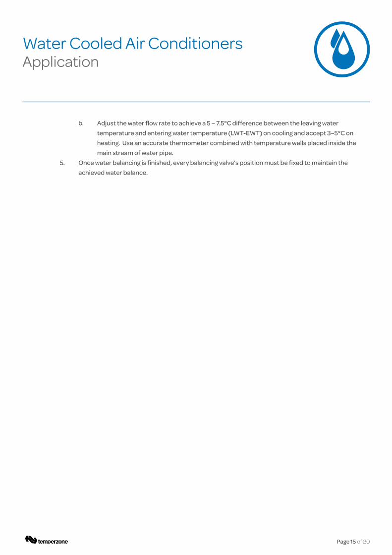
b. Adjust the water flow rate to achieve a 5 – 7.5°C difference between the leaving water temperature and entering water temperature (LWT-EWT) on cooling and accept 3–5°C on heating. Use an accurate thermometer combined with temperature wells placed inside the main stream of water pipe.
5. Once water balancing is finished, every balancing valve’s position must be fixed to maintain the achieved water balance.
Water Cooled Air Conditioners Application

Page 16 of 20
Water Cooled Air Conditioners Application
9. PRE START-UP CHECKS
Before commencing, both power supply and water supply should be connected and ready for all the water cooled units. The water loop pipes must have been flushed, vented of air and cleaned.
Perform the following checks and record the results on a Commissioning Sheet (refer page 18) before start-up of a unit:
1. Water connections to the unit have been completed and the flow direction is the same as indicated on the unit. The service valves should be fully open and the balancing valve left in the mid position.
2. If an automatic flow control valve is used, check that the appropriate size cartridge has been inserted which complies with the unit’s designated nominal flow rate (refer unit’s Specifications Sheet or Technical Data instructions).
3. Check the drain by pouring water into the drain tray and ensuring that it clears.
4. Where spring mounts are used, adjust the spring on each of the four corners so they are evenly depressed. Check the unit is sitting on the springs freely.
5. Check air filtration is fitted in the system and is accessible for cleaning and/or replacement.
6. Check that the thermostat is correctly wired to the unit and is set at the desired temperature.
7. Check the supply voltage is between: 220 – 240 volts (single phase), 380 – 415 volts (three phase).

Page 17 of 20
Water Cooled Air Conditioners Application
10. TEST RUN
Test run the unit on both cooling and heating (if applicable) cycles and check the following :
1. Measure entering water temperature and record it on the Commissioning Sheet (refer page 18). If the water temperature difference (TD) method is used to balance the water distribution, the leaving water temperature is also to be measured. Set water TD at 5-7°C on cooling or 3-5°C on heating.
2. Measure the current draw on the compressor motor and the current draw of the fan motor. Check all readings against the specified valves in the Specification Sheet.
3. The measuring of suction and discharge pressures is discouraged. Each unit has been accurately pre-charged in the factory. Some units have only 400 grams refrigerant charge in total. Each unnecessary measurement will let out 20-40 g of charge which will affect the unit performance. The HWP unit’s UC8 controller can display pressures without the need to connect guages, or you can use a temperzone WiFi Service Utility (WSU).
4. Measure the air temperature, both on to the unit and off the unit and record.
5. Check system total air flow to prove unit design air flow is being provided.
6. Check the supply air flow at each outlet. Balance the air distribution.
7. Listen for any unusual noises coming from the unit, unit mounting or ducting, and if there is any, correct them.
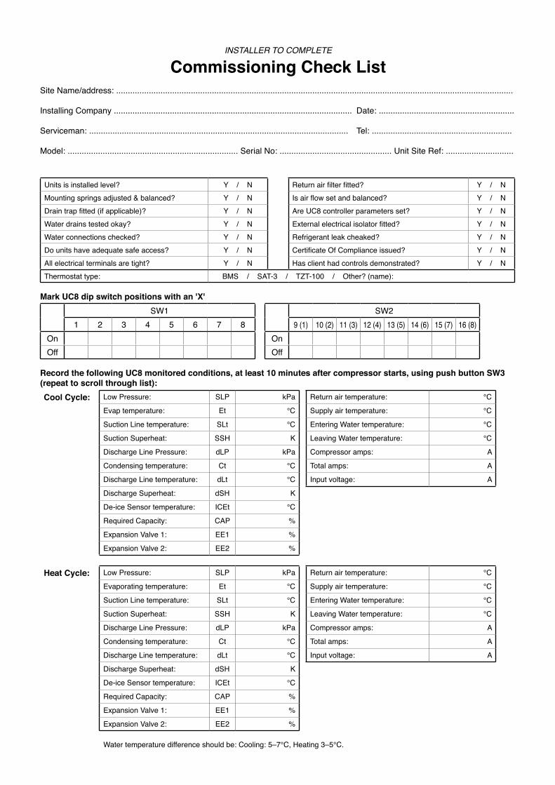
INSTALLER TO COMPLETE
Commissioning Check ListSite Name/address: ..........................................................................................................................................................................
Installing Company ...................................................................................................... Date: ..........................................................
Serviceman: ............................................................................................................... Tel: ............................................................
Model: ......................................................................... Serial No: ................................................ Unit Site Ref: .............................
Units is installed level? Y / N Return air filter fitted? Y / NMounting springs adjusted & balanced? Y / N Is air flow set and balanced? Y / NDrain trap fitted (if applicable)? Y / N Are UC8 controller parameters set? Y / NWater drains tested okay? Y / N External electrical isolator fitted? Y / NWater connections checked? Y / N Refrigerant leak cheaked? Y / NDo units have adequate safe access? Y / N Certificate Of Compliance issued? Y / NAll electrical terminals are tight? Y / N Has client had controls demonstrated? Y / NThermostat type: BMS / SAT-3 / TZT-100 / Other? (name):
Mark UC8 dip switch positions with an 'X'SW1 SW2
1 2 3 4 5 6 7 8 9 (1) 10 (2) 11 (3) 12 (4) 13 (5) 14 (6) 15 (7) 16 (8)
On OnOff Off
Record the following UC8 monitored conditions, at least 10 minutes after compressor starts, using push button SW3 (repeat to scroll through list):Cool Cycle: Low Pressure: SLP kPa Return air temperature: °C
Evap temperature: Et °C Supply air temperature: °C
Suction Line temperature: SLt °C Entering Water temperature: °C
Suction Superheat: SSH K Leaving Water temperature: °C
Discharge Line Pressure: dLP kPa Compressor amps: A
Condensing temperature: Ct °C Total amps: A
Discharge Line temperature: dLt °C Input voltage: A
Discharge Superheat: dSH K
De-ice Sensor temperature: ICEt °C
Required Capacity: CAP %
Expansion Valve 1: EE1 %
Expansion Valve 2: EE2 %
Heat Cycle: Low Pressure: SLP kPa Return air temperature: °C
Evaporating temperature: Et °C Supply air temperature: °C
Suction Line temperature: SLt °C Entering Water temperature: °C
Suction Superheat: SSH K Leaving Water temperature: °C
Discharge Line Pressure: dLP kPa Compressor amps: A
Condensing temperature: Ct °C Total amps: A
Discharge Line temperature: dLt °C Input voltage: A
Discharge Superheat: dSH K
De-ice Sensor temperature: ICEt °C
Required Capacity: CAP %
Expansion Valve 1: EE1 %
Expansion Valve 2: EE2 %
Water temperature difference should be: Cooling: 5–7°C, Heating 3–5°C.

Page 19 of 20
Water Cooled Air Conditioners Notes

Available from
05/18 Pamphlet No. 4100© temperzone limited 2018
www.temperzone.biz
� � � � � � � �
����������
AUCKLAND
Head Office38 Tidal Rd, Mangere, N.Z.Private Bag 93303, Otahuhu, NEW ZEALAND.
Email [email protected] Phone (09) 279 5250Fax (09) 275 5637
WELLINGTON
Phone (04) 569 3262Fax (04) 566 6249
CHRISTCHURCH
Phone (03) 379 3216Fax (03) 379 5956
SYDNEY
Head Office14 Carnagie Place, Blacktown, NSW 2148PO Box 8064, Seven Hills West, NSW 2147, AUSTRALIA.
Email [email protected] Phone (02) 8822 - 5700Fax (02) 8822 - 5711
ADELAIDE
Phone (08) 8115 - 2111Fax (08) 8115 - 2118
MELBOURNE
Phone (03) 8769 - 7600Fax (03) 8769 - 7601
BRISBANE
Phone (07) 3308 - 8333 1800 897 253Fax (07) 3308 - 8330
PERTH
Phone (08) 6399 - 5900Fax (08) 6399 - 5932
NEWCASTLE
Phone (02) 4962 - 1155Fax (02) 4961 - 5101
LAUNCESTON
Phone 1800 897 253Fax (07) 3308 - 8330
J AKARTA
Phone +62 (21) 2963 4983Fax +62 (21) 2963 4984
SINGAPORE
Phone +65 6733 4292Fax +65 6235 7180
SHANGHAI
Phone +86 (21) 5648 2078