hvac systems investigation & retro...
TRANSCRIPT
P.S. 260 Q / P.S. 307
40-20 100th Street
Queens, NY 11368
HVAC Systems Investigation
& Retro Commissioning
NEBB Certified in Building Systems Retro-Commissioning
Airpath Engineering, PC40-08 Oser Avenue
Hauppauge, New York 11788
Goals of Investigation
1. To verify RTU-1 and RTU-2 system performance
2. To determine if RTU-1 and RTU-2 can deliver design air flow
and pressure to all connected VAV terminals
3. To investigate how air system diversity affects flow and cooling
performance
4. To report the deficiencies that limit system performance
5. To verify and/or correct flow parameters and calibrations of the
VAV air terminals
Information From Previous Balancing Report
The previous balancing firm reported that the total
connected air load is significantly higher than the specified
capacity of each unit
It was also reported that not all VAVs are able to achieve
design flow
All inconsistencies that have been reported have been verified
by Airpath
Issues Limiting RTU Performance
There are two separate factors that are creating excessively
large pressure drops in the RTU systems.
1. The gas heat section of RTU-1 and RTU-2 both have an
inherently high air friction loss that was not accounted for in
the fan total static pressure from internal component air
friction calculation. This is mainly a problem in RTU-1.
Issues Limiting RTU Performance
There are two separate factors that are creating excessively
large pressure drops in the RTU systems.
2. The sound trap in the discharge ductwork of the RTU-1
system is installed in a position that produces high air
friction loss and limits the flow to some of the vertical
supply air risers.
Issues Limiting RTU Performance
Significantly low supply air duct pressure is preventing many
terminals on the RTU-1 system from achieving design flow,
including FPB-108, FPB-207, FPB-212, FPB-312, FPB-410, FPB-
506, FPB-508, and FPB-510.
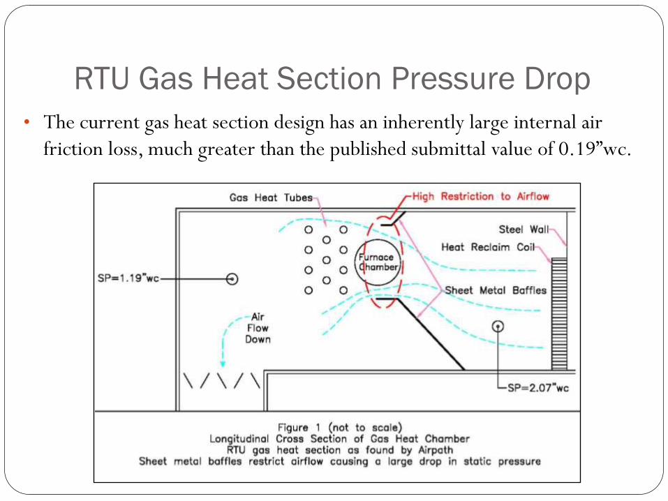
RTU Gas Heat Section Pressure Drop
• The current gas heat section design has an inherently large internal air
friction loss, much greater than the published submittal value of 0.19”wc.
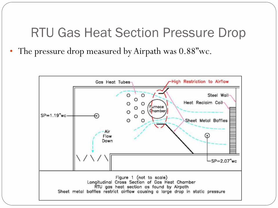
RTU Gas Heat Section Pressure Drop
• The pressure drop measured by Airpath was 0.88”wc.
RTU Gas Heat Section Pressure Drop
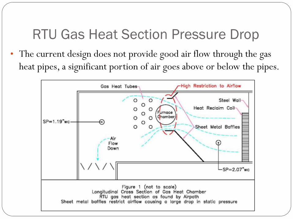
• The current design does not provide good air flow through the gas
heat pipes, a significant portion of air goes above or below the pipes.
RTU Gas Heat Section
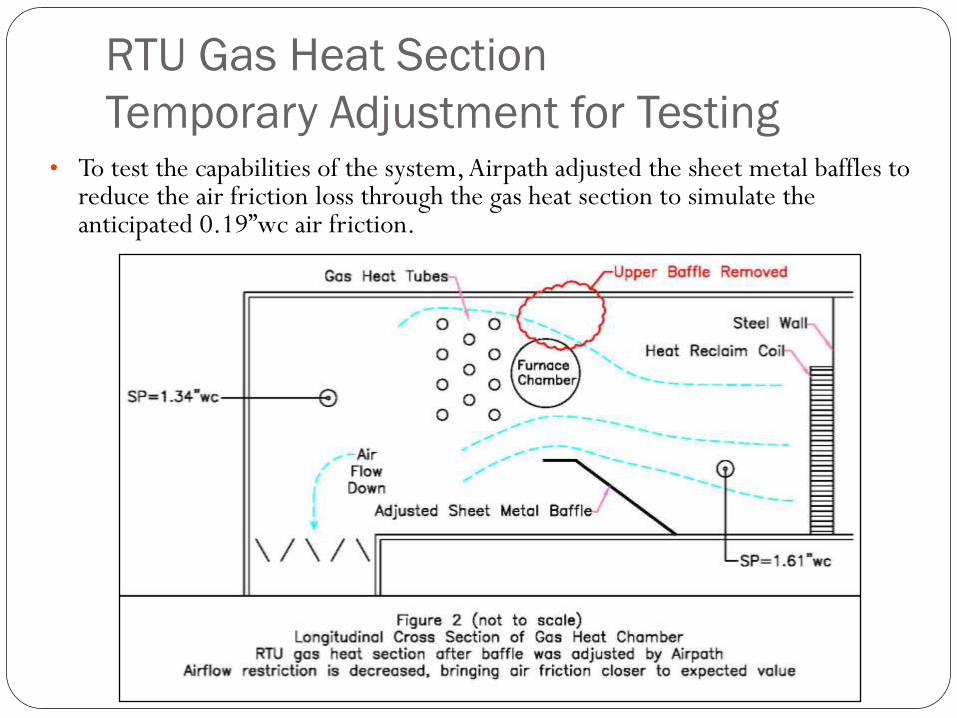
Temporary Adjustment for Testing• To test the capabilities of the system, Airpath adjusted the sheet metal baffles to
reduce the air friction loss through the gas heat section to simulate the anticipated 0.19”wc air friction.
RTU Gas Heat Section
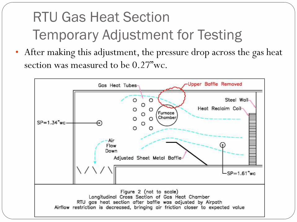
Temporary Adjustment for Testing• After making this adjustment, the pressure drop across the gas heat
section was measured to be 0.27”wc.
RTU Gas Heat Section
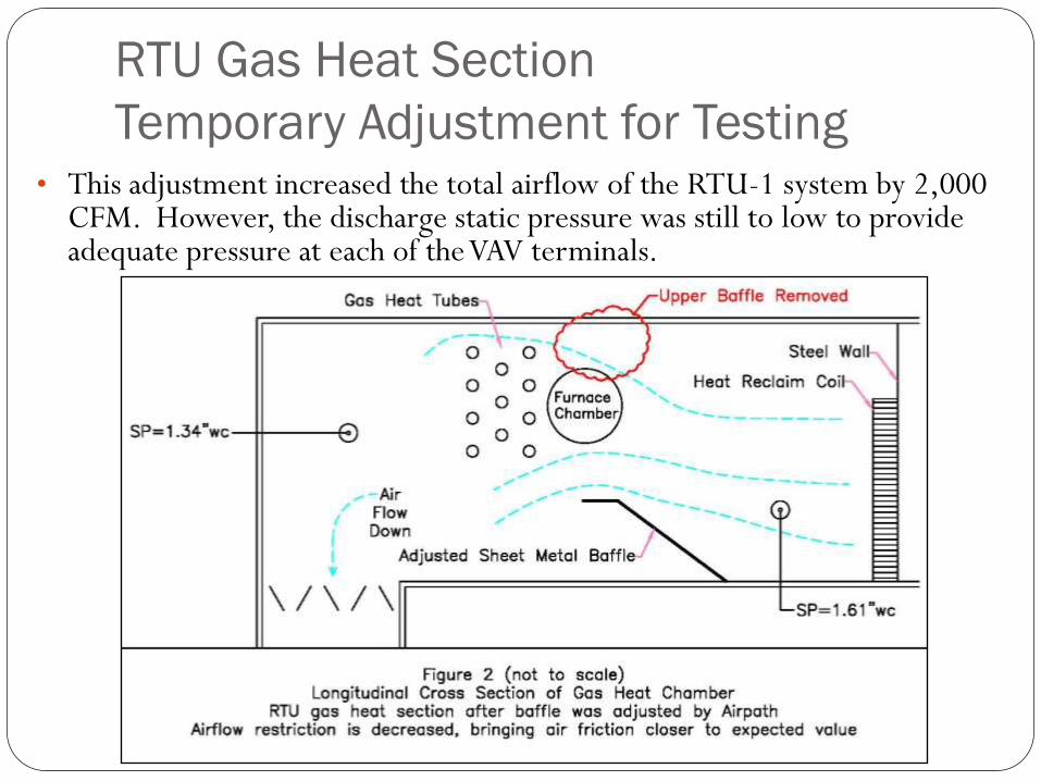
Temporary Adjustment for Testing• This adjustment increased the total airflow of the RTU-1 system by 2,000
CFM. However, the discharge static pressure was still to low to provide adequate pressure at each of the VAV terminals.
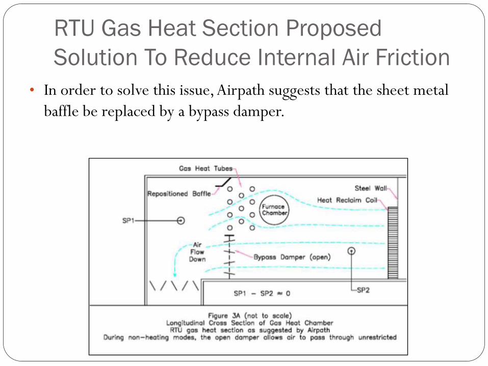
RTU Gas Heat Section Proposed
Solution To Reduce Internal Air Friction
• In order to solve this issue, Airpath suggests that the sheet metal
baffle be replaced by a bypass damper.
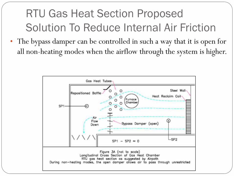
RTU Gas Heat Section Proposed
Solution To Reduce Internal Air Friction• The bypass damper can be controlled in such a way that it is open for
all non-heating modes when the airflow through the system is higher.

RTU Gas Heat Section Proposed
Solution To Reduce Internal Air Friction
During heating mode the damper would close to direct the air flow
through the gas heat pipes.
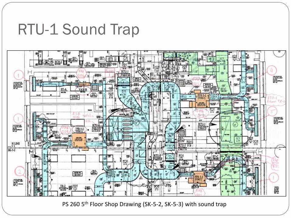
PS 260 5th Floor Shop Drawing (SK-5-2, SK-5-3) with sound trap
RTU-1 Sound Trap
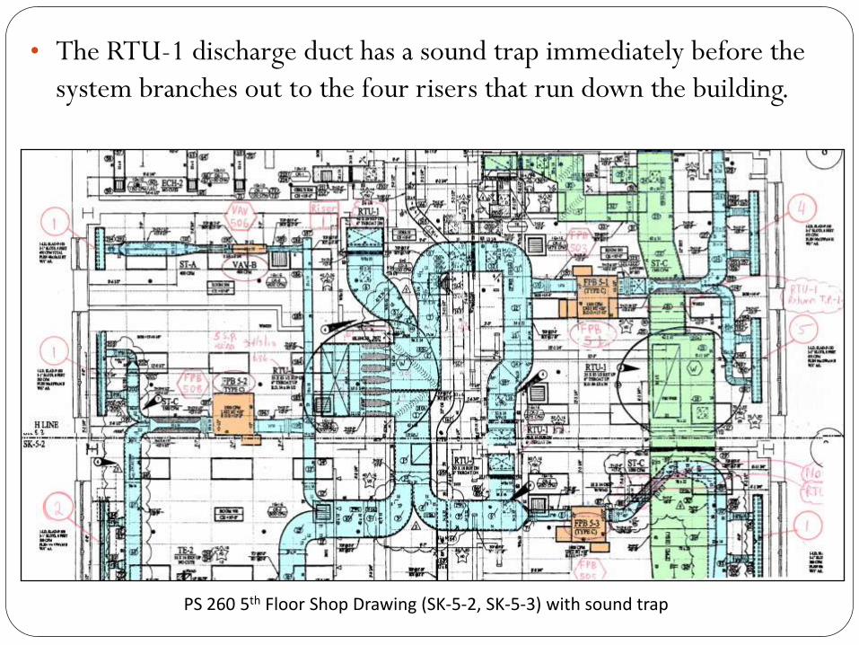
• The RTU-1 discharge duct has a sound trap immediately before the
system branches out to the four risers that run down the building.
PS 260 5th Floor Shop Drawing (SK-5-2, SK-5-3) with sound trap
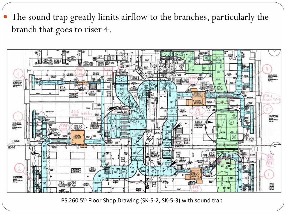
The sound trap greatly limits airflow to the branches, particularly the
branch that goes to riser 4.
PS 260 5th Floor Shop Drawing (SK-5-2, SK-5-3) with sound trap
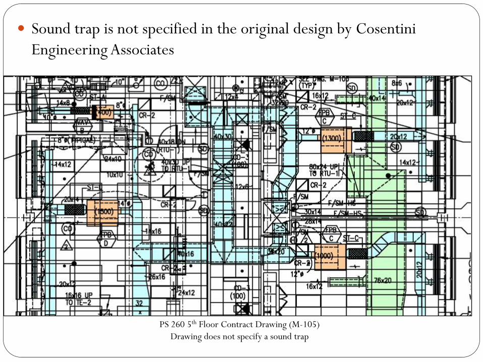
Sound trap is not specified in the original design by Cosentini
Engineering Associates
PS 260 5th Floor Contract Drawing (M-105)
Drawing does not specify a sound trap
Why was a sound trap added?
Is it possible that the pressure loss of the sound trap was not
anticipated in the original supply air duct design external static
pressure calculation by Cosentini Engineering Associates
RTU-1 Sound Trap Solution
Airpath believes that the sound trap core may be removed
internally and the duct can be relined with new duct liner.
Removing the core of the sound trap will allow the airflow to
be correctly distributed among the four risers, and also
reduce the air friction loss in the duct… more air pressure
shall be available at the vertical risers.
RTU Rooftop Misplacement
• It was reported to Airpath by the SCA that the RTU-1 and
RTU-2 units were misplaced in each other’s rooftop locations
during the initial installation
• It was originally believed that the only difference between
the units was the return fan and return fan motor
• Airpath discovered that the supply fan pressure class, as well
as the supply fan motors, were also different
RTU Rooftop Placement, continued
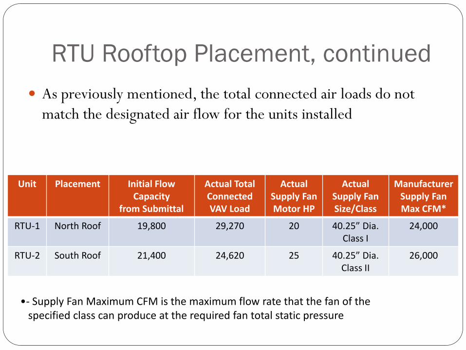
As previously mentioned, the total connected air loads do not
match the designated air flow for the units installed
Unit Placement Initial Flow Capacity
from Submittal
Actual Total ConnectedVAV Load
Actual Supply FanMotor HP
Actual Supply FanSize/Class
Manufacturer Supply Fan Max CFM*
RTU-1 North Roof 19,800 29,270 20 40.25” Dia.Class I
24,000
RTU-2 South Roof 21,400 24,620 25 40.25” Dia.Class II
26,000
•- Supply Fan Maximum CFM is the maximum flow rate that the fan of the specified class can produce at the required fan total static pressure
Consequences of RTU Reversal
• Unfortunately, although the sizes of the supply fans in RTU- 1 and 2
are identical, RTU-1 specifies a class II fan. This fan is currently
installed in RTU-2, and the class I fan for RTU-2 is in RTU-1.
Therefore the present RTU-1 has a class I fan, where a class II fan is
required.
• This limits the maximum air flow capability of RTU-1. The only way
to achieve design flow would be to replace the fan and motor. This is
an impractical solution
• System performance can be improved by resolving the previously
mentioned issues, but it will likely never be able to fully satisfy all
terminals with the currently installed fan
Alternate solution
• Airpath suggests isolating one branch of the RTU-1 system and
connecting it to a new smaller rooftop air conditioning unit. The
branch that connects to riser 4 as well as 3 of the 5th floor VAV
terminals is preferable. A new 15-20 ton rooftop air conditioner
would be able to satisfy the connected VAV terminal load of 7450
CFM. A 15 ton RTU will have an 80% diversity, a 20 ton RTU
will be evenly matched to the outlet load.
• The currently installed fan in RTU-1 will be able to satisfy the
other 3 risers (21,820 CFM) without much diversity.
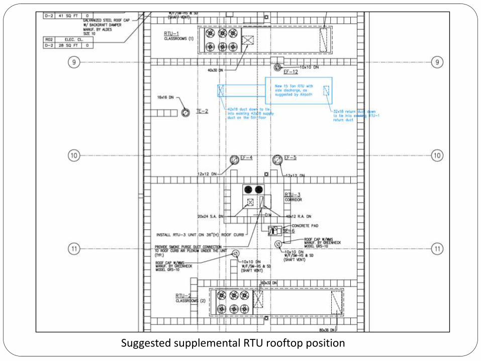
Suggested supplemental RTU rooftop position
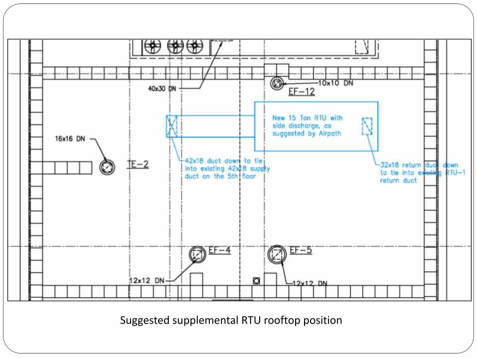
Suggested supplemental RTU rooftop position
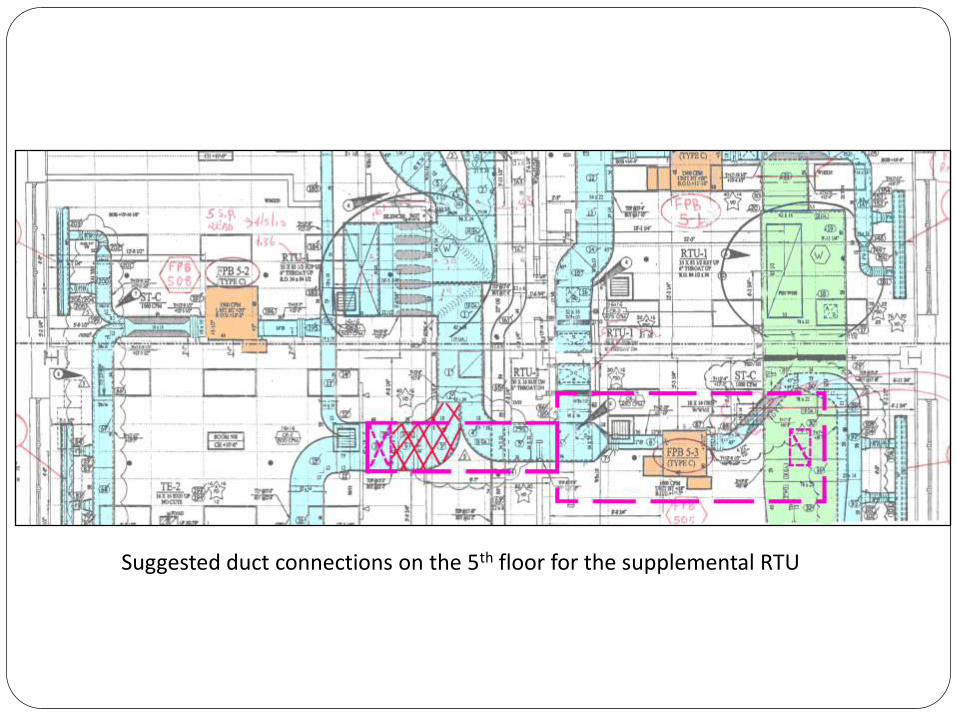
Suggested duct connections on the 5th floor for the supplemental RTU
Fan Powered VAV Inlet Dampers
• Airpath discovered volume dampers installed on the inlet
ductwork of many of the FP VAV terminals on the second floor.
These dampers are unnecessary and restrict airflow to the
terminals.
• Dampers are shown on the Blue Diamond sheet metal shop
drawings but not specified on the contract drawings.
• Airpath fully opened these to maximize airflow to the terminals.
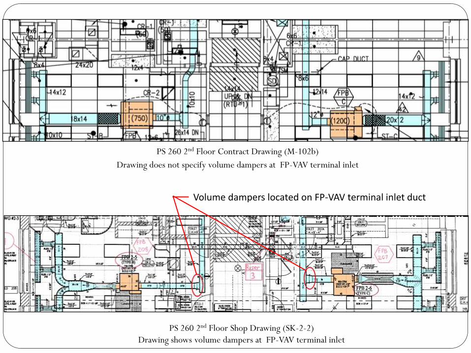
Volume dampers located on FP-VAV terminal inlet duct
PS 260 2nd Floor Contract Drawing (M-102b)
Drawing does not specify volume dampers at FP-VAV terminal inlet
PS 260 2nd Floor Shop Drawing (SK-2-2)
Drawing shows volume dampers at FP-VAV terminal inlet
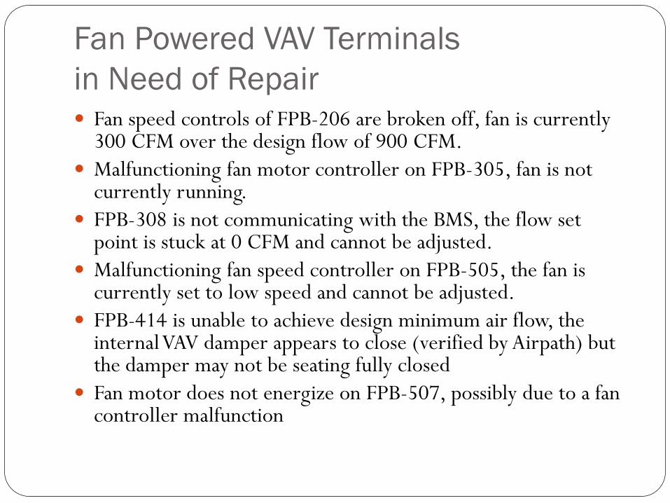
Fan Powered VAV Terminals
in Need of Repair Fan speed controls of FPB-206 are broken off, fan is currently
300 CFM over the design flow of 900 CFM.
Malfunctioning fan motor controller on FPB-305, fan is not currently running.
FPB-308 is not communicating with the BMS, the flow set point is stuck at 0 CFM and cannot be adjusted.
Malfunctioning fan speed controller on FPB-505, the fan is currently set to low speed and cannot be adjusted.
FPB-414 is unable to achieve design minimum air flow, the internal VAV damper appears to close (verified by Airpath) but the damper may not be seating fully closed
Fan motor does not energize on FPB-507, possibly due to a fan controller malfunction
Results
Airpath believes that addressing the issues that have been
presented, both the RTU-1 and RTU-2 systems can attain
dramatically increased performance and that each of the
connected FP VAV terminals will be able to properly
maintain the temperature in the building.
Summary of Possible Upgrades1. Relocate the upper internal gas heat section baffle and install a
bypass damper below the gas furnace in the configuration
illustrated by Airpath, and approved by the manufacturer.
Control the bypass damper to close when the RTU is in heating
mode (furnace on)
2. Remove the sound trap core in the RTU-1 discharge ductwork
and reline the duct
3. Isolate the branch of the RTU-1 supply duct connected to riser
4 and the 3 VAV terminals, and install a 15 ton RTU dedicated
for all the connected air terminals in this isolated section
4. Repair miscellaneous terminals listed in the report