hv-series - halton · main components the hv-series blast dampers comprise ... performance of the...
TRANSCRIPT

1
HV-series - Blast Dampers
HV-series Blast Dampers are designed for protection
of ventilation systems against the effects of vapor and
dust cloud explosions. The HV-series Blast Dampers
are applied in shielding of industrial facilities, such as
Oil & Gas platforms and refineries or related buildings
against destructive blast forces. The HV-series offers
substantially higher air flow capacity and increased level
of safety, as well as flexibility in design of duct systems.
Structure of the HV-series damper is corrosion free, hot
dip galvanized steel or EN 1.4404 (AISI316L) in the HV-
SS version.
The HV-series damper has spring loaded closing blades
built in a fully welded damper body to close the air
passage in case of explosion or sudden increase of
overpressure in the HVAC system. The threshold trigger
pressure of the damper can be adjusted according to
customer specification.
Once closed the blades will remain in closed position
until they are manually reset after the incident.
The HV-series dampers are available as ATEX certified
(optional).
Main components
The HV-series Blast dampers comprise of the following
main components:
• HV-blast damper is manufactured of galvanized or
stainless steel, EN 1.4404 (AISI316L)
• Fully welded damper body made of 5 mm steel
• Closing blades and shafts provided with stainless
steel bearings
• Adjustable trigger mechanism
• Fragment grill
• Positive and negative phase protection
HV-SERIESBlast Dampers
2
HV-series - Blast Dampers
Design criteria
The HV-series Blast Damper is designed for hazardous
environments with a possibility of dust or vapor cloud
explosion. Design criteria is a long duration pressure
wave with finite rise time and 1 bar (14,5 psi) peak
overpressure. HV-series blast damper can be adjusted
to close on a minimum overpressure of 0,03 bar (0,44
psi).
Test and performance data
Performance of the HV-series Blast Damper is
verified by tests in a large scale vapor cloud explosion
simulator to effectively attenuate slowly rising (rise
time over 300 ms) long duration pressure wave loads
within the load range up to 1.0 bar. The damper is also
tested to withstand the impact of high velocity flying
objects according to ASTM E 1886 – 05 and 1996 – 05.
The damper is designed to function within the operating
temperature range of -50…+80ºC. In high heat related
to explosion, 300ºC for 40 min.
Product coding
The HV-series Blast Dampers are coded as follows:
• Blast Damper HV-700x700 = damper width
700mm, damper height 700mm, material hot dip
galvanized steel
• Blast Damper HV-1500x1500-SS = damper width
1500mm, damper height 1500mm, material
stainless steel AISI316L
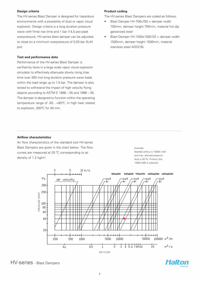
Airflow characteristics
Air flow characteristics of the standard size HV-series
Blast Dampers are given in the chart below. The flow
curves are measured at 20 ºC corresponding to air
density of 1.2 kg/m3.
Example:
Needed airflow is 15000 m3/h
and max. allowed pressure
drop is 40 Pa. Product size
1000x1000 is selected.
PR
ES
SU
RE
DR
OP
AIR FLOW

3
HV-series - Blast Dampers
V6M
07Y
2016
/Hal
ton
Mar
ine
rese
rves
th
e ri
gh
t to
alt
er p
rod
uct
s w
ith
ou
t n
oti
ce.
Opening max. (mm)
Blast DamperSteel wall Concrete wall Dimensions (mm) Weight
A B K L F G H kgHV-300x300 300 300 130 130 340 95 95 55
HV-500x500 500 500 350 350 560 130 130 95
HV-700x700 700 700 550 550 760 80 80 170
HV-1000x1000 1000 1000 850 850 1060 80 80 300
HV-1500x1500 1500 1500 1370 1370 1580 115 115 535
GENERAL DRAWING OF HV-BLAST DAMPER
The HV-series Blast Dampers are dimensioned
according to the duct size or wall opening.
Standard sizes are:
• 300 mm x 300 mm
• 500 mm x 500 mm
• 700 mm x 700 mm
• 1000 mm x 1000 mm
• 1500 mm x 1500 mm
The dampers are also available in custom sizes with
steps of 100 mm in each direction between the limits.
Note: G and H are greater than 75 mm but less than or equal to 150 mm.
The nominated duct size (internal) is A x B (width x height).
Flanges are also available according to ISO 15138 standard.
Operational mechanism side
C
D
A
B
E
F
G G
HH
Ø14
150
150
150 150
BM
BM
HV Blast Damper Size
The following list presents common details to address
in determining the blast damper size:
• Airflow requirement
• Duct size
• Maximum allowable pressure drop
• Wall thickness and composition
• Damper mounting alternative
• Material (hot dip galvanized or stainless steel)
4
HV-series - Blast Dampers
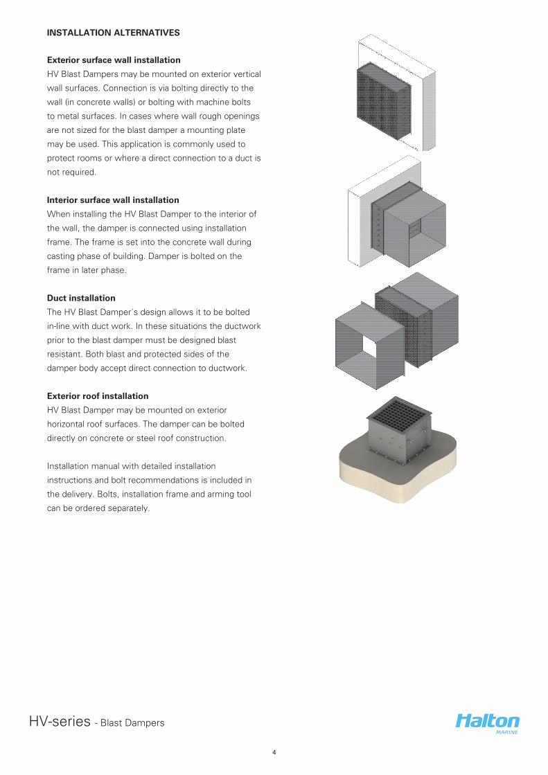
INSTALLATION ALTERNATIVES
Exterior surface wall installation
HV Blast Dampers may be mounted on exterior vertical
wall surfaces. Connection is via bolting directly to the
wall (in concrete walls) or bolting with machine bolts
to metal surfaces. In cases where wall rough openings
are not sized for the blast damper a mounting plate
may be used. This application is commonly used to
protect rooms or where a direct connection to a duct is
not required.
Interior surface wall installation
When installing the HV Blast Damper to the interior of
the wall, the damper is connected using installation
frame. The frame is set into the concrete wall during
casting phase of building. Damper is bolted on the
frame in later phase.
Duct installation
The HV Blast Damper´s design allows it to be bolted
in-line with duct work. In these situations the ductwork
prior to the blast damper must be designed blast
resistant. Both blast and protected sides of the
damper body accept direct connection to ductwork.
Exterior roof installation
HV Blast Damper may be mounted on exterior
horizontal roof surfaces. The damper can be bolted
directly on concrete or steel roof construction.
Installation manual with detailed installation
instructions and bolt recommendations is included in
the delivery. Bolts, installation frame and arming tool
can be ordered separately.