hurricane shutter design considerations for florida · one of the best ways to protect a home...
TRANSCRIPT

One of the best ways to protect a home (Group R occupancy) from damage in windstorms is to install shutters over all
windows and glass doors. Shutters protect windows from wind-borne objects. They also prevent structural damage caused
by sudden pressure changes when a window is broken.
Hurricane Shutter Design Considerations for Florida
Figure 1
Wind-Borne deBris regions and VULT ConToUrs for deTermining appLiCaBiLiTy of TaBLes r301.2.1.2 and 1609.1.2 of The 2010 fLorida BUiLding Codes
Broward
Hendry
PalmBeach
Charlotte Glades
MartinDesoto
Sarasota
SaintLucie
Okeechobee
ManateeHardee
Highlands
Pinellas
Hillsborough
Osceola
Polk
OrangeSumter
Lake
Marion
Flagler
Alachua
BradfordWakulla Taylor
Suwannee Col
umbi
a
HamiltonMadison
Jeffe
rson
Leon
Gadsden
WaltonHolmes
Pinellas
d
h
Browar
PalmBeach
Martin
SaintLucie
Hendry
Charlotte Glades
DesotoSarasota
Okeechobee
ManateeHard
S
PinellasPinellas
H
PPPinellas
ardeeHighlands
Hillsborough
Osceola
Polk
OrangeSumter
Lake
gler
Marion
Flag
Alachua
Bradford
Walton
Wakulla
Holmes
kulla Taylor
Suwannee Col
umbi
a
HamiltonMadison
Jeffe
rson
Leon
Gadsden
Wind-Borne Debris Region as Defined in Section R202
Designated areas where the basic wind speed, VULT , is 140 mph or greater.
130 mph, VULT and within 1 mile of the coast
Notes:
1) Values are VULT 3-second gust, wind speeds in miles per hour at 33 ft above ground for Exposure C category.
2) Linear interpolation between contours is permitted.
3) Islands and coastal areas outside the last contour shall use the last wind speed contour of the coastal area.
4) Mountainous terrain, gorges, ocean promontories, and special wind regions shall be examined for unusual wind conditions.
5) This map is accurate to the county. Local governments establish specific wind speed/wind-borne debris lines using physical landmarks such as major roads, canals, rivers and shorelines.
6) VASD = ��0.6 x VULT
Source: Adapted from the 2010 Florida Building Code and Florida Building Code – Residential (Figures 1609A and R301.2(4), respectively).
ggg
ard
Hi
arde
Hi
arde
Hi
L
SS
L
S
d
h
r
mh
rd
mh
115120
120130
130
140
140
140
140
150
150
150
150
160
160
170
170
180
180
115

Hurricane Shutter Design Considerations for Florida
Form No. T460A ■ © 2013 APA – The Engineered Wood Association ■ www.apawood.org
2
The following designs are presented as two basic alternatives: The first is to present the code minimum opening protec-
tion when such shutters are required. The requirements of the 2010 Florida Building Code-Residential (FBC-R) and
2010 Florida Building Code-Building (FBC-B) are presented. Except for Dade and Broward Counties, they permit the
use of minimum 7/16 Performance Category Rated Sheathing as opening protection against the impact of wind-borne
debris. Check with local building departments for verification or clarification of requirements.
The second approach provides some design details for stronger and stiffer shutters than provided for by the code-
minimum requirements. It should be noted that these designs were developed prior to the adoption of specific stan-
dards for shutter designs by any U.S. codes. The supports detailed for these shutters meet code requirements when
mounted according to the specifications in Table R301.2.1.2 of the FBC-R. The mounting brackets for the masonry
block structures have been tested for design wind loads but have not been impact or cyclic tested because they were
developed as design guides before these standards were developed.
1. Code-MiniMuM Shutter deSign
2010 Florida Building Code–Residential (FBC-R) Section R301.2.1.2 Protection of Openings. Windows
in buildings located in wind-borne debris regions shall have glazed openings protected from wind-borne debris. Glazed
opening protection for wind-borne debris shall meet the requirements of the large missile test of ASTM E1996 and ASTM
E1886, SSTD 12, TAS 201, 202 and 203 or AAMA 506 referenced therein. Garage door glazed opening protection
for wind-borne debris shall meet the requirements of an approved impact resisting standard or ANSI/DASMA 115.
1. Openings in sunrooms, balconies or enclosed porches constructed under existing roofs or decks are not required
to be protected provided the spaces are separated from the building interior by a wall and all openings in the
separating wall are protected in accordance with this section. Such space shall be permitted to be designed as
either partially enclosed or enclosed structures.
2. Storage sheds that are not designed for human habitation and that have a floor area of 720 square feet or less
are not required to comply with the mandatory wind-borne debris impact standard of this code.
3. Ventilation openings in an exterior wall into an attic space in buildings located in wind-borne debris regions
shall have opening protection from wind-borne debris. Such opening protection into an attic space shall meet
the requirements of AMCA 540 or shall be protected by an impact resistant cover complying with an approved
impact-resistance standard or the large missile test of ASTM E1996.
Impact resistant coverings shall be tested at 1.5 times the design pressure (positive or negative) expressed in pounds
per square feet as determined by the Florida Building Code, Residential Section R301, for which the specimen is
to be tested.
Exception: Wood structural panels with a minimum thickness of 7/16 inch and a maximum span of 8 feet shall be
permitted for opening protection in one- and two-story buildings. Panels shall be precut and attached to the framing
surrounding the opening containing the product with the glazed opening. Panels shall be predrilled as required for
the anchorage method and shall be secured with the attachment hardware provided. Attachments shall be designed
to resist the component and cladding loads determined in accordance with either Table R301.2(2) or ASCE 7 with
the permanent corrosion-resistant attachment hardware provided and anchors permanently installed on the building.
Attachment in accordance with Table R301.2.1.2 is permitted for buildings with a mean roof height of 33 feet or less
where VASD determined in accordance with Section R301.2.1.3 does not exceed 130 miles per hour.

Hurricane Shutter Design Considerations for Florida
Form No. T460A ■ © 2013 APA – The Engineered Wood Association ■ www.apawood.org
3
Sections R202 and 1609.2 define Wind-borne Debris Region as:
Wind-borne Debris Region. Areas within hurricane-prone regions located:
1. Within 1 mile of the coastal mean high water line where the ultimate design wind speed is VulT , is 130 mph or
greater; or
2. In areas where the ultimate design wind speed, VulT , is 140 mph or greater.
Section R202 defines Hurricane-Prone Regions as:
Hurricane-Prone Regions. Areas vulnerable to hurricanes defined as:
1. The u.S. Atlantic Ocean and Gulf of Mexico coasts where the basic wind speed, VulT , for Risk Category II buildings
is greater than 115 mph and
2. Hawaii, Puerto Rico, Guam, Virgin Islands and American Samoa.
Alternatively, Section 1609.1.2 of the 2010 Florida Building Code-Building, Protection of Openings:
1609.1.2 Protection of Openings. Glazed openings in buildings located in wind-borne debris regions shall be
protected from wind-borne debris. Glazed opening protection for wind-borne debris shall meet the requirements of
SSTD 12, ASTM E1886 and ASTM E1996, ANSI/DASMA 115 (for garage doors and rolling doors) or TAS 201, 202
and 203 or AAMA 506 referenced therein.
1. Glazed openings located within 30 feet of grade shall meet the requirements of the large missile test of ASTM E1996.
2. Glazed openings located more than 30 feet above grade shall meet the provisions of the small missile test of
ASTM E1996.
3. Storage sheds that are not designed for human habitation and that have a floor area of 720 square feet or less
are not required to comply with the mandatory wind-borne debris impact standards of this code.
Table r301.2.1.2
Wind-Borne deBris proTeCTion fasTening sChedULe for Wood sTrUCTUraL paneLs(a)(b)(c)(d)
fastener Type
fastener spacing (inches)(a)(b)
panel span ≤ 4 Feet
4 Feet < Panel Span ≤ 6 Feet
6 Feet < Panel Span ≤8 Feet
No. 8 wood-screw-based anchor with 2-inch embedment length 16 10 8
No. 10 wood-screw-based anchor with 2-inch embedment length 16 12 9
1/4-inch lag-screw-based anchor with 2-inch embedment length 16 16 16
For Si: 1 inch = 25.4 mm, 1 foot = 304.8 mm, 1 pound = 4.448 N, 1 mile per hour = 0.447 m/s.
(a) This table is based on VASD determined in accordance with Section r301.2.1.3, 130 mph and a 33-foot mean roof height.
(b) Fasteners shall be installed at opposing ends of the wood structural panel. Fasteners shall be located a minimum of 1 inch from the edge of the panel.
(c) anchors shall penetrate through the exterior wall covering with an embedment length of 2 inches minimum into the building frame. Fasteners shall be located a minimum of 2-1/2 inches from the edge of concrete block or concrete.
(d) Where panels are attached to masonry or masonry/stucco, they shall be attached using vibration-resistant anchors having a minimum ultimate withdrawal capacity of 1500 pounds.

Hurricane Shutter Design Considerations for Florida
Form No. T460A ■ © 2013 APA – The Engineered Wood Association ■ www.apawood.org
4
4. Openings in sunrooms, balconies or enclosed porches constructed under existing roofs or decks are not required
to be protected provided the spaces are separated from the building interior by a wall and all openings in the
separating wall are protected in accordance with Section 1609.1.2. Such spaces shall be permitted to be designed
as either partially enclosed or enclosed structures.
Exceptions:
1. Wood structural panels with a minimum thickness of 7/16 inch and maximum span of 8 feet shall be permitted for
opening protection in one- and two-story buildings classified as Group R-3 or R-4 occupancy. Panels shall be precut
so that they shall be attached to the framing surrounding the opening containing the product with the glazed opening.
Panels shall be predrilled as required for the anchorage method and shall be secured with the attachment hardware
provided. Attachments shall be designed to resist the components and cladding loads determined in accordance with
the provisions of ASCE 7, with corrosion-resistant attachment hardware provided and anchors permanently installed
on the building. Attachment in accordance with Table 1609.1.2 with corrosion-resistant attachment hardware provided
and anchors permanently installed on the building is permitted for buildings with a mean roof height of 45 feet or less
where VASD , determined in accordance with Section 1609.3.1 does not exceed 140 mph. (See Figure 1 for wind-borne
debris regions and VulT contours.)
2. Glazing in Risk Category I buildings as defined in Section 1604.5, including greenhouses that are occupied for growing
plants on a production or research basis, without public access shall be permitted to be unprotected.
3. Glazing in Risk Category II, III or IV buildings located over 60 feet above the ground and over 30 feet above
aggregate surface roofs located within 1,500 feet of the building shall be permitted to be unprotected.
4. Exterior balconies or porches under existing roofs or decks enclosed with screen or removable vinyl and acrylic
panels complying with Section 2002.3.3 shall not be required to be protected and openings in the wall separating
the unit from the balcony or porch shall not be required to be protected unless required by other provisions of
this code.
Table 1609.1.2
Wind-Borne deBris proTeCTion fasTening sChedULe for Wood sTrUCTUraL paneLs(a)(b)(c)(d)
fastener Type
fastener spacing (inches)
panel span ≤ 4 Feet
4 Feet < Panel Span ≤ 6 Feet
6 Feet < Panel Span ≤ 8 Feet
No. 8 wood-screw-based anchor with 2-inch embedment length 16 10 8
No. 10 wood-screw-based anchor with 2-inch embedment length 16 12 9
1/4-inch diameter lag-screw-based anchor with 2-inch embedment length
16 16 16
For Si: 1 inch = 25.4 mm, 1 foot = 304.8 mm, 1 pound = 4.448 N, 1 mile per hour = 0.447 m/s.
a. This table is based on VASD determined in accordance with Section 1609.3.1 of 140 mph and a 45-foot mean roof height.
b. Fasteners shall be installed at opposing ends of the wood structural panel. Fasteners shall be located a minimum of 1 inch from the edge of the panel.
c. anchors shall penetrate through the exterior wall covering with an embedment length of 2 inches minimum into the building frame. Fasteners shall be located a minimum of 2-1/2 inches from the edge of concrete block or concrete.
d. Where panels are attached to masonry or masonry/stucco, they shall be attached using vibration-resistant anchors having a minimum ultimate withdrawal capacity of 1,500 pounds.

Hurricane Shutter Design Considerations for Florida
Form No. T460A ■ © 2013 APA – The Engineered Wood Association ■ www.apawood.org
5
2. ConSiderationS for Stronger, Stiffer deSignS
The following design pages describe how to construct stronger, stiffer shutters for attachment to wood and masonry
walls. The masonry attachments were designed prior to the adoption of specific test standards for shutter designs
by Florida codes. The shutters have been tested to resist the design wind loads and impacts, but the attachments to
masonry have not been impact or cyclic-load tested. The masonry attachment details are therefore supplied as guides
in developing individual designs.
Section R4403.2.1(g) (for Dade and Broward Counties) requires that shutters deflect no more than the shutter span
(in inches) divided by 30 (for instance, a 40-inch span should not bend more than 40"/30 = 1.33 inches when the
wind blows). They also should bend less than 2 inches maximum and should remain at least one inch away from the
window when under full wind force.
In wood-frame construction, panels can be nailed over the openings when a hurricane approaches. Buildings made
with concrete blocks, however, require advance preparation.
In some cases, stiffeners may be necessary to limit deflection of the shutter against the glass. Stiffeners function best
if they are on the outside of the shutter and oriented with the narrow edge against the shutter.
Tables 1 and 2 and Figures 2 and 3 on the following pages apply to most of the designs, and are referenced accordingly.
These APA hurricane shutter designs are based on pressures associated with a three-second gust VULT wind speed of
190 mph (VAsd wind speed of 150 mph) and a mean roof height of 45 feet or less. Before constructing shutters, it is
important to check with your local building department for any updates on current code requirements.
Note: The shutter designs shown herein will provide significant protection from hurricane-force winds. This publication contains recom-mendations to serve as a guide only. It does not include all possible shutter, anchor and fastening systems, and the installer must adjust all dimensions to compensate for particular installations and hardware used. These shutter designs by no means represent all possible workable designs and can always be upgraded to provide even greater margins of safety and protection. All shutter designs herein are intended to be temporary and mounted and removed from outside the building. All designs are based on wind-pressure capacities only.
While the design wind pressures used are based on ASCE 7-10, the building owner/installer must still carefully evaluate each system and then, if necessary, make any modifications consistent with good design and building practices.

Hurricane Shutter Design Considerations for Florida
Form No. T460A ■ © 2013 APA – The Engineered Wood Association ■ www.apawood.org
6
Table 1
maximUm span WiThoUT sTiffeners – sTrengTh axis perpendiCULar To fasTener roWs (see figUre 2)
apa panel span rating
approximate Weight
(psf)
maximum shutter span
(in.)
approximate deflection at VULT 190 mph design Wind speed at 45-ft Height, Exp. C, Wet Panels
(in.)
32/16 1.5 22 0.22
40/20 2.1 30 0.38
48/24 2.4 34 0.35
48 oc 3.6 50 0.58
Table 2
WeighTs and defLeCTions of shUTTers WiTh sTiffeners(a) (see figUre 3)
apa panel span rating
minimum panel specification
approximate Weightmaximum span
(stiffener Bending)Total deflection
(stiffener plus panel)
With 2x4 stiffeners
(psf)
With 2x6 stiffeners
(psf)
With 2x4 stiffeners(b) at 16" o.c.
(in.)
With 2x6 stiffeners(b) at 16" o.c.
(in.)
66" span with 2x4 stiffeners
(in.)
96" span with 2x6 stiffeners
(in.)
32/16, 15/32 Perf. Cat. 5-ply plywood or OSb
2.4 2.9 66 96 0.87 0.97
40/20, 19/32 Perf. Cat. 4-ply plywood or OSb
2.8 3.3 66 96 0.75 0.86
48/24, 23/32 Perf. Cat. Plywood or OSb
3.2 3.7 66 96 0.66 0.79
48 o.c., 1-1/8 Perf. Cat. Plywood or OSb
4.3 4.8 66 96 0.49 0.67
(a) Panels with 2x4 S-P-F (South) No. 2 stiffeners spaced 16 inches o.c., exposure C, 3-second gust, Wall Zone 5, mean roof height = 45 ft, VulT 190 mph, 2010 FbC-r.
(b) Maximum span governed by stiffener bending strength, wet stresses, duration of load factor = 1.6.

Hurricane Shutter Design Considerations for Florida
Form No. T460A ■ © 2013 APA – The Engineered Wood Association ■ www.apawood.org
7
Rows of fasteners
Panel shutter Shutter span
Panel strength axis(perpendicular to the fastener rows)
Orientation is based on Figure A1
Figure 2
shUTTer insTaLLaTion exampLe shoWing orienTaTion of paneL sTrengTh axis
APA structural panel No. 2 2x4 or No. 2 2x6
Cut if desired
Panel strength axis
3/16" x 3" lag screws with fender washers
Min. 16d box nails (0.135" x 3-1/2") @ 6" o.c.
Figure 3
shUTTer sTiffener aTTaChmenT – if reqUired

Hurricane Shutter Design Considerations for Florida
Form No. T460A ■ © 2013 APA – The Engineered Wood Association ■ www.apawood.org
8
hurriCane Shutter deSignS index
Hurricane Shutter Design Considerations for Florida
Form No. T460A ■ © 2013 APA – The Engineered Wood Association ■ www.apawood.org
9
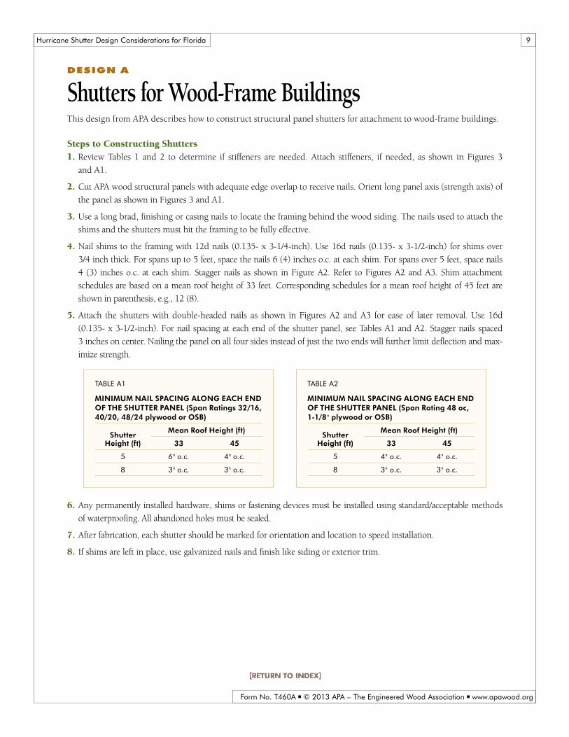
deSign a
Shutters for Wood-Frame BuildingsThis design from APA describes how to construct structural panel shutters for attachment to wood-frame buildings.
Steps to Constructing Shutters1. Review Tables 1 and 2 to determine if stiffeners are needed. Attach stiffeners, if needed, as shown in Figures 3
and A1.
2. Cut APA wood structural panels with adequate edge overlap to receive nails. Orient long panel axis (strength axis) of
the panel as shown in Figures 3 and A1.
3. Use a long brad, finishing or casing nails to locate the framing behind the wood siding. The nails used to attach the
shims and the shutters must hit the framing to be fully effective.
4. Nail shims to the framing with 12d nails (0.135- x 3-1/4-inch). Use 16d nails (0.135- x 3-1/2-inch) for shims over
3/4 inch thick. For spans up to 5 feet, space the nails 6 (4) inches o.c. at each shim. For spans over 5 feet, space nails
4 (3) inches o.c. at each shim. Stagger nails as shown in Figure A2. Refer to Figures A2 and A3. Shim attachment
schedules are based on a mean roof height of 33 feet. Corresponding schedules for a mean roof height of 45 feet are
shown in parenthesis, e.g., 12 (8).
5. Attach the shutters with double-headed nails as shown in Figures A2 and A3 for ease of later removal. Use 16d
(0.135- x 3-1/2-inch). For nail spacing at each end of the shutter panel, see Tables A1 and A2. Stagger nails spaced
3 inches on center. Nailing the panel on all four sides instead of just the two ends will further limit deflection and max-
imize strength.
Table a1
minimUm naiL spaCing aLong eaCh end of The shUTTer paneL (Span Ratings 32/16, 40/20, 48/24 plywood or OSB)
shutter height (ft)
mean roof height (ft)
33 45
5 6" o.c. 4" o.c.
8 3" o.c. 3" o.c.
Table a2
minimUm naiL spaCing aLong eaCh end of The shUTTer paneL (Span Rating 48 oc, 1-1/8" plywood or osB)
shutter height (ft)
mean roof height (ft)
33 45
5 4" o.c. 4" o.c.
8 3" o.c. 3" o.c.
6. Any permanently installed hardware, shims or fastening devices must be installed using standard/acceptable methods
of waterproofing. All abandoned holes must be sealed.
7. After fabrication, each shutter should be marked for orientation and location to speed installation.
8. If shims are left in place, use galvanized nails and finish like siding or exterior trim.

Hurricane Shutter Design Considerations for Florida
Form No. T460A ■ © 2013 APA – The Engineered Wood Association ■ www.apawood.org
10
16d (0.135" x 3-1/2") double-headed nails in accordance with Tables A1 and A2
APA structural panel
No. 2 2x4s or No. 2 2x6s (if needed)
Cut if desired
Panel strength axis
Span
Figure a1
shUTTer aTTaChmenT – VieW from oUTside
16d (0.135" x 3-1/2") double-headed nails per Table A1 or A2
Siding
Shim
Shutter
Finish wall
Flashing and caulk
Glass
Header
16d (0.135" x 3-1/2") nailsholding shims per Step 4
Interior casing
Maintain a minimum panel edge distance of 1/2" –1"
Figure a2
shUTTer aTTaChmenT – Top

Hurricane Shutter Design Considerations for Florida
Form No. T460A ■ © 2013 APA – The Engineered Wood Association ■ www.apawood.org
11
Caulk (prior to installing shim)
16d (0.135" x 3-1/2") nailsholding shims per Step 4
Shim
Siding
Finish sill
Finish wall
Shutter
SillInterior casing
Glass
Maintain a minimum panel edge distance of 1/2" –1"
16d (0.135" x 3-1/2") double-headed nails per Table A1 or A2
Figure a3
shUTTer aTTaChmenT – BoTTom

Hurricane Shutter Design Considerations for Florida
Form No. T460A ■ © 2013 APA – The Engineered Wood Association ■ www.apawood.org
12
deSign B
Shutters for Masonry Block Structures Barrel-Bolt latch supports
This design from APA describes how to construct structural panel shutters for attachment to masonry block buildings
using barrel-bolt latch supports. The unique features of this design are the barrel bolt latches that support the shutter
at either end. Once made, the shutters can be mounted or removed without any additional hardware or tools. The
barrel-bolt latches should be mounted to the panel with bolts rather than the screws that usually come with them. Use
a washer under the nuts and heads of the bolts. Place the nut-end of the bolts to the outside (latch side) of the shutter
to allow for final adjustment of the latches.
Steps to Constructing Shutters1. Use Tables 1 and 2 to determine if stiffeners are needed. Attach stiffeners, if needed, as shown in Figure 3.
2. Cut the panel 1/8 inch less than the window opening. The long-panel axis (strength axis) must be oriented perpendicular
to the supported ends (sides of the shutter with the barrel bolts), regardless of which shutter dimension is longer.
3. Make two templates that will help in mounting the latches and
drilling the barrel-bolt latch holes in the concrete blocks – one
for each side of the window. The maximum distance between
the top of the shutter panel and the first barrel bolt, and the
maximum distance between barrel bolts shall be in accordance
with Table B1 and should miss the mortar joints between the
blocks by 1-1/2 inches or more. See Figure B1.
4. Mount 4-inch barrel bolts. The nuts go on the latch side (outside)
of the shutter. Make the nuts only finger tight because the latches
will be adjusted in the final fitting.
5. Drill latch-bolt holes in blocks. See Figure B2.
6. Mount the shutter in the window frame, and insert the barrel-
bolt latches into the holes in the concrete blocks. Tighten bolts holding barrel bolts in place.
7. The barrel-bolt holes in the concrete blocks may be filled with a removable plug when not in use as shown in Figure B3.
8. Any permanently installed hardware, shims or fastening devices must be installed using standard/acceptable methods of
waterproofing. All abandoned holes must be sealed.
9. After fabrication, each shutter should be marked for orientation and location to speed installation.
10. To prevent the bottom 2x4 anchor holes in the concrete block from becoming clogged with dirt between shutter
uses, insert 1/2-inch No. 14 pan- or flat-head screws into the anchor holes. Remove these screws prior to reattaching
the 2x4s.
Table b1
BarreL BoLT aTTaChmenT sChedULe
shutter Width
(ft)
mean roof height (ft)
33 45
distance to first Barrel Bolt (in.)
5 6 5
8 4 3
Barrel Bolt spacing (in.)
5 12 10
8 8 6

Hurricane Shutter Design Considerations for Florida
Form No. T460A ■ © 2013 APA – The Engineered Wood Association ■ www.apawood.org
13
Figure b1
LaTCh BoLT pLaCemenT deTaiLs
1-1/2"
Panel strength axis
TOP NORTH SIDE
CENTER
4" barrel bolt
No. 8 machine screws
3/8" cut washersAPA structural panel
Hole for latch bolt
Masonry joints
Outside face of wall
Note: Be sure to mark the location and orientationof each shutter after fabrication
4'' Barrel bolt
Section view of barrel bolt
Wall end view
Front view
Distance to first barrel bolt per Table B1
1-1/2"
Barrel bolt spacing per Table B1
Figure b2
LaTCh-BoLT hoLe in side of WindoW opening
Block Stucco
Holes for latchbolts not greater
than 16" o.c.
1-1/2"minimum
1"
Figure b3
Temporary pLUg for LaTCh-BoLT hoLe
Stucco
Block
Hole forlatch bolt
CorkScrew handle
Plug forlatch-bolt hole

Hurricane Shutter Design Considerations for Florida
Form No. T460A ■ © 2013 APA – The Engineered Wood Association ■ www.apawood.org
14
deSign C
Shutters for Masonry Block Structures steel or aluminum angle and screw supports
This design from APA describes how to construct structural panel shutters for attachment to masonry block buildings,
using steel or aluminum angle and screw supports. The design is less costly to build than shutters with permanent
hardware for attachment and removal.
Anchorage to Masonry BlockThe plastic anchors* referenced in this plan have sufficient lateral and withdrawal capacity to handle the expected
forces and are recommended because they are rated as being vibration resistant – a characteristic that may be of some
value under buffeting wind loads. (Standard lead anchors are not usually rated as vibration resistant.)
Keep masonry anchors at least 1-1/2 inches from the block edges, joints and corners to minimize the danger of cracking the
concrete blocks.
Steps to Constructing Shutters1. Use Tables 1 and 2 to determine if stiffeners are needed. Attach stiffeners, if needed, as shown in Figure 3.
2. In the dimension from support to support, cut the panel 3/8 inch less than the measurement of the window opening
(side to side in Figure C1). In the dimension from unsupported edge to unsupported edge, cut the panel 1/8 inch
less than the measurement of the opening. The long-panel axis (strength axis) must be oriented perpendicular to the
supported sides (side to side in Figure C1), regardless of which shutter dimension is longer.
3. Cut 1-1/2 x 1-1/2 x 1/8-inch steel or aluminum angles to the same length as the width of the shutter ends to be
supported.
4. Drill 1/4-inch diameter holes per Table C1 in one side of the angle. These holes are for bolts that hold the angle to
the panel and may be centered between the corner and the edge of the angle.
5. Drill 3/16-inch diameter holes per Table C2 in the remaining leg of the angle, offset 1 inch from the panel bolt holes.
Make the centerline of the holes 1/4 inch from edge of the angle. These holes are to receive No. 10 screws that will
go through the holes into masonry anchors in the concrete blocks. Refer to Figure C2.
Table C2
hoLe LoCaTions in angLe for aTTaChmenT To WaLL
shutter Width
(ft)
mean roof height (ft)
33 45
Concrete anchor spacing (in.)
5 8 8
8 6 4
distance to first Concrete anchor (in.)
5 4 4
8 3 2
Table C1
hoLe LoCaTions in angLe for aTTaChmenT of shUTTer paneL
shutter Width
(ft)
mean roof height (ft)
33 45
machine Bolt spacing (in.)
5 12 12
8 12 12
distance to first machine Bolt (in.)
5 6 6
8 6 6
*Lateral ultimate value 350 lbs or greater in 4,000 psi concrete, with screws specified (1-1/2 inches with stucco).

Hurricane Shutter Design Considerations for Florida
Form No. T460A ■ © 2013 APA – The Engineered Wood Association ■ www.apawood.org
15
6. Drill holes in blocks for the plastic anchors. Refer to Figure C3.
7. Mount the shutter, with angles mounted, to the window frame using No. 10 x 1-1/2" screws with washers.
See Figure C1.
8. Any permanently installed hardware, shims or fastening devices must be installed using standard/acceptable methods
of waterproofing. All abandoned holes must be sealed.
9. After fabrication, each shutter should be marked for orientation and location to speed installation.
10. To prevent the bottom 2x4 anchor holes in the concrete block from becoming clogged with dirt between shutter
uses, insert 1/2-inch No. 14 pan- or flat-head screws into the anchor holes. Remove these screws prior to reattaching
the 2x4s.
Hurricane Shutter Design Considerations for Florida
Form No. T460A ■ © 2013 APA – The Engineered Wood Association ■ www.apawood.org
16
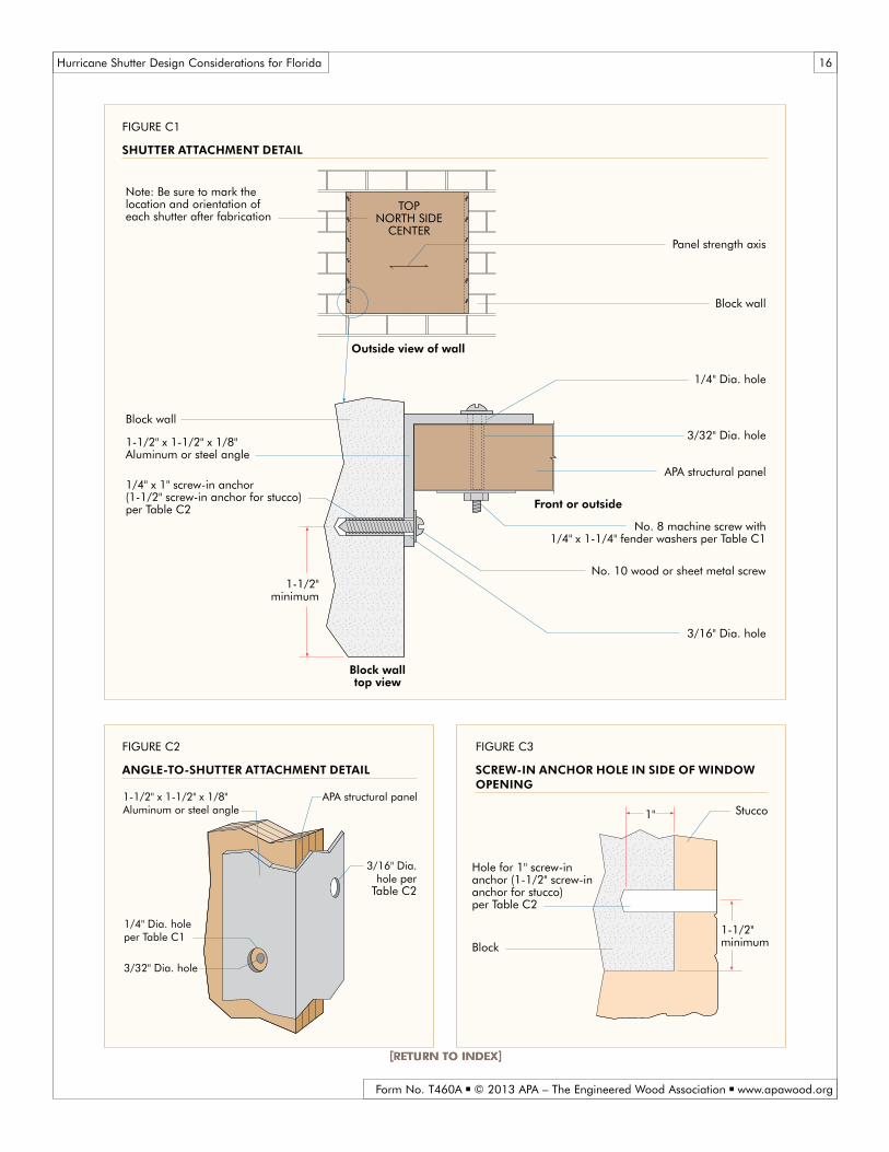
Figure C1
shUTTer aTTaChmenT deTaiL
Panel strength axis
TOPNORTH SIDE
CENTER
Block wall
Note: Be sure to mark the location and orientation of each shutter after fabrication
1-1/2"minimum
APA structural panel
1/4" Dia. hole
3/32" Dia. hole1-1/2" x 1-1/2" x 1/8"Aluminum or steel angle
No. 10 wood or sheet metal screw
1/4" x 1" screw-in anchor(1-1/2" screw-in anchor for stucco)per Table C2
3/16" Dia. hole
Outside view of wall
Block wall
Block walltop view
No. 8 machine screw with 1/4" x 1-1/4" fender washers per Table C1
Front or outside
Figure C2
angLe-To-shUTTer aTTaChmenT deTaiL
Figure C3
sCreW-in anChor hoLe in side of WindoW opening
1/4" Dia. holeper Table C1
3/32" Dia. hole
3/16" Dia.hole per
Table C2
APA structural panel1-1/2" x 1-1/2" x 1/8"Aluminum or steel angle Stucco
Block
Hole for 1'' screw-inanchor (1-1/2" screw-inanchor for stucco)per Table C2
1-1/2"minimum
1"

Hurricane Shutter Design Considerations for Florida
Form No. T460A ■ © 2013 APA – The Engineered Wood Association ■ www.apawood.org
17
deSign d
Shutters for Masonry Block Structures shutters attached to outside wall with permanently mounted Brackets
This design from APA describes how to construct structural panel shutters for attachment to masonry block buildings, using
permanently mounted brackets on the outside wall. Two layers of APA Exterior plywood are attached to the outside of the concrete
block wall with No. 10 flat-head screws in masonry anchors. Once the brackets are installed, no tools are required to install or
remove the shutters unless stiffeners are required. It has the advantage of moving the shutter almost 2 inches farther away from
the glass than shutters mounted to the interior of the window frame and is therefore less likely to require stiffeners.
FastenersScrews or bolts that will be permanently exposed to the weather should be made of stainless steel.
Anchorage to Masonry BlockThe plastic anchors* referenced in this plan have sufficient lateral and withdrawal capacity to handle the expected
forces and are recommended because they are rated as being vibration resistant – a characteristic that may be of some
value under buffeting wind loads. (Standard lead anchors are not usually rated as vibration resistant.)
Keep masonry anchors at least 1-1/2 inches from the block edges, joints and corners to minimize the danger of cracking the
concrete blocks.
Steps to Constructing Shutters1. Use Tables 1 and 2 to determine if stiffeners are needed. Attach stiffeners, if needed, as shown in Figure 3.
2. Cut APA Exterior plywood for the shutter support/spacer and
for the trim that holds shutter against the supports (see Figure
D1). Make the thickness of the inner spacer slightly greater
than that of the shutter to allow the shutters to slide without
binding. (The inner trim spacer of plywood is left out of one
side of the window framing to allow for the insertion of the
shutters.) Orient the plywood face grain of the trim as indi-
cated in the diagram. (Plywood with four or more plies may
be oriented either direction.) Lap the corners to allow the
outer trim to be attached to the inner spacer at the corners.
Refer to Figure D1.
3. Drill 1/2-inch diameter vertical drain holes in bottom inner
spacer to allow rain water to escape out the bottom.
4. Cut the shutter to be 1/4 inch less than the distance from the bottom of the bottom slot to the top of the top slot, and
about 2 inches wider than the window opening width (assuming that the panels are supported top and bottom).
Orient the long-panel axis (strength axis) as shown in Figure D1. Slide the shutter into place.
5. Drill hole halfway down the trim and diagonally downward (at about 30 degrees from the surface) in the trim board
covering the shutter-entrance opening. The hole should be about 1/8 inch outside the edge of the installed shutter.
This hole will receive a 12d box (0.128 x 3-1/4-inch) nail to prevent the shutter panel or panels from getting blown
back out the entrance slot.
*Withdrawal ultimate value 490 lbs or greater in 4,000 psi concrete, with screws specified (1-1/2 inches with stucco).
Table D1
Trim-To-ConCreTe anChor spaCing
shutter height
(ft)
mean roof height (ft)
33 45
Concrete anchor spacing (in.)
5 12 12
8 9 6
distance to first Concrete anchor (in.)
5 6 6
8 4 3

Hurricane Shutter Design Considerations for Florida
Form No. T460A ■ © 2013 APA – The Engineered Wood Association ■ www.apawood.org
18
6. Any permanently installed hardware, shims or fastening devices must be installed using standard/acceptable methods of
waterproofing. All abandoned holes must be sealed.
7. After fabrication, each shutter should be marked for orientation and location to speed installation.
8. To prevent the bottom 2x4 anchor holes in the concrete block from becoming clogged with dirt between shutter uses,
insert 1/2-inch No. 14 pan- or flat-head screws into the anchor holes. Remove these screws prior to reattaching the 2x4s.
Design AlternativeAs an alternative to Design D, the wood trim can be replaced with 1 x 1 x 1-inch (outside measurements) x 1/8-inch
aluminum channels (channel outside dimensions may be changed to better accommodate panels thicker than 5/8 inch i.e.,
1-1/8-inch-thick shutters will require a channel slot opening of about 1-1/4 inches) mounted approximately the same way as
the wood trim. See Figure D2. Make holes at both ends to hold a latching device to prevent shutters from being blown out.
APA structural panel shutter
1/2" Plywood face trim
No. 10 screw
1/4" x 1" Screw-in anchor(1/4" x 1-1/2" for stucco) in accordance with Table D1
Panel strength axis
Inner spacer
1-1/2" Minimum
Note: Using sawn lumber instead of plywood for the outer layer of trim may result in the failure of the trim when suction loads are applied to the shutter.
Detail of locking device
Face trim
Not required forreinforced shutters
Hole forshutter stop
Side view
Lap trim at corners
Shutter location –marked on shutter
Shutter slot (3 sides)
Strength axis
Drain hole
Block
3" 4"
Thickness of shutter plus 1/8"
TOPNORTH SIDE
CENTER
Figure D1
shUTTer frame and aTTaChmenT – sTrUCTUraL paneL opTion

Hurricane Shutter Design Considerations for Florida
Form No. T460A ■ © 2013 APA – The Engineered Wood Association ■ www.apawood.org
19
Figure D2
shUTTer frame and aTTaChmenT – aLUminUm ChanneL opTion
1/4" x 1" screw-in anchor(1/4" x 1-1/2" for stucco) inaccordance with Table D1
Stucco
Block
1-1/2"Minimum
1/2"
Aluminum channel1" x 1" x 1" x 1/8"
No. 10 screw

Hurricane Shutter Design Considerations for Florida
Form No. T460A ■ © 2013 APA – The Engineered Wood Association ■ www.apawood.org
20
deSign e
Shutters for Masonry Block Structures For openings wider than 8 Feet
This design from APA describes how to construct structural panel shutters for attachment to masonry block build-
ings, where glass windows and doors are wider than 8 feet. The shutters run from top to bottom and are attached to a
temporary 2x4 lumber strip at the top and bottom of the opening.
Anchorage to Masonry BlockThe plastic anchors* referenced in this plan have sufficient lateral and withdrawal capacity to handle the expected
forces and are recommended because they are rated as being vibration resistant – a characteristic that may be of some
value under buffeting wind loads. (Standard lead anchors are not usually rated as vibration resistant.)
Keep masonry anchors at least 1-1/2 inches from the block edges, joints and corners to minimize the danger of cracking
the concrete blocks.
Steps to Constructing Shutters1. Use Table 2 to determine which panel to use.
2. Cut two 2x4s to a length that is 1 inch less than the width of the door opening to be covered. Rip the 2x4s length-
wise, if necessary, to the width of the distance of the door frame to the front of the wall. The outside edge of the 2x4
should be flush with the outside surface of the wall. (Note: If holes or hole plugs on the front of the building are not
a concern, the top 2x4 may be eliminated by extending the shutter above the opening and attaching the top of the
shutter directly to the front of the header.) Refer to Figure E1.
3. Predrill 1/4-inch diameter holes in the 2x4s in accordance with Table E1 and at least 1-1/2 inches from the front
edge of the 2x4s (outside surface of the wall).
4. Drill holes in the concrete blocks.
5. Tap vibration-resistant anchors into the holes in the concrete.
6. Attach the 2x4s to top and bottom of the opening using 2-1/2-inch No. 14 round or pan-head wood or sheetmetal
screws with washers. Refer to Figure E1.
7. Cut the shutter to span the opening (plus the width of the supports, 3 inches for two 2x4s). Orient the long-panel
axis (strength axis) as shown in Figure 3.
8. Drill holes at 16 inches o.c. along the supported panel edges and in the 2x4s.
9. Attach the shutter to the 2x4s with 2-inch No. 10 wood or sheetmetal screws in accordance with Table E2.
10. To prevent the bottom 2x4 anchor holes in the concrete block from becoming clogged with dirt between shutter
uses, insert 1/2-inch No. 14 pan- or flat-head screws into the anchor holes. Remove these screws prior to reattaching
the 2x4s.
11. Any permanently installed hardware, shims or fastening devices must be installed using standard/acceptable
methods of waterproofing. All abandoned holes must be sealed.
12. After fabrication, each shutter should be marked for orientation and location to speed installation.
* Withdrawal ultimate value 490 lbs or greater in 4,000 psi concrete, with screws specified (1-1/2 inches with stucco).

Hurricane Shutter Design Considerations for Florida
Form No. T460A ■ © 2013 APA – The Engineered Wood Association ■ www.apawood.org
21
Figure e1
shUTTer aTTaChmenT To header and sLaB fLoor
No. 10 x 2" screw with washerin accordance with with Table E2
Concrete floor
APA structural panel
Header reinforcing
No. 14 x 2-1/2" screw with washer in accordance with Table E1
3/16" x 3" lag screw with fender washer
16d nails 6" o.c.
Anchor
No. 14 x 2-1/2" screw with washer in accordance with Table E1
2x4
2x4
Header
Shutter location and orientation
TOPWEST SLIDER
LEFT SIDE
No. 2 2x4 16" o.c.or No. 2 2x6 16" o.c.
Alternate means of attachmentNo. 14 x 2-1/2" screw with washer and
anchor through 2x4 in accordance with Table E3
Patio slab
No. 10 x 2" screw with washerin accordance with Table E2
Alternate means of attatchment No. 14 x 2-1/2" screw with washer and
anchor in accordance with Table E3
Anchor
Anchor
2x4 (if required)
Outside of shutterMin.
1-1/2"
Min.1-1/2"
Outside surface of wall
Table e2
shUTTer To Temporary 2x4
shutter Width
(ft)
mean roof height (ft)
33 45
no. 10 screw spacing (in.)
5 8 8
8 4 4
distance to first no. 10 screw (in.)
5 4 4
8 2 2
Table e1
Temporary 2x4 tO COnCREtE
shutter Width
(ft)
mean roof height (ft)
33 45
no. 14 Screw Spacing (in.)
5 12 12
8 8 6
Distance to First no. 14 screw anchor (in.)
5 6 6
8 4 3
Table e3
Top of shUTTer To header (alternate means)
shutter Width
(ft)
mean roof height (ft)
33 45
Concrete anchor spacing (in.)
5 6 6
8 4 4
distance to first Concrete anchor (in.)
5 3 3
8 2 2

Hurricane Shutter Design Considerations for Florida
We have field representatives in many major u.S. cities and in Canada who can help answer questions involving aPa trademarked products. For additional assistance
in specifying engineered wood products, contact us:
apa headqUarTers7011 So. 19th St. ■ Tacoma, Washington 98466
(253) 565-6600 ■ Fax: (253) 565-7265
prodUCT sUpporT heLp desk(253) 620-7400
e-mail address: [email protected]
disCLaimerThe information contained herein is based on APA – The Engineered Wood Association’s continuing programs of laboratory testing, product research, and comprehensive field experi-ence. Neither APA, nor its members make any warranty, expressed or implied, or assume any legal liability or responsibility for the use, application of, and/or reference to opinions, findings, conclusions, or recommendations included in this publication. Consult your local jurisdiction or design professional to assure compliance with code, construction, and performance require-ments. Because APA has no control over quality of workmanship or the conditions under which engineered wood products are used, it cannot accept responsibility of product performance or designs as actually constructed.
Form No. T460a/revised September 2013