hurricane ike wind investigation report
TRANSCRIPT


HURRICANE IKE INVESTIGATION REPORT December 2009
Team Captains & Main Report Writers
Mike Barton ARMKO Industries
Dr. A. Baskaran National Research Council of Canada
John Goveia Technical Roof Services, Inc.
David Hunt Revere Copper Products, Inc.
Phil Mayfield PSM Consultants, Inc.
David Roodvoets DLR Consultants
Walter Rossiter WJ Rossiter & Associates
Robb Smith Amtech Building Sciences, Inc.
William Woodring GAF Materials Corporation
Patricia Wood-Shields RICOWI, Inc.
Logistics Team
Warren French & Staff French Engineering, Inc.
John Goveia Technical Roof Services, Inc.
Phil Mayfield PSM Consultants, Inc.
Paul Riesebieter Malarkey Roofing Products
Robb Smith Amtech Building Sciences, Inc.
Project Managers
Patricia Wood-Shields RICOWI, Inc.
David Roodvoets DLR Consultants
Peer Reviewers Phil Mayfield
PSM Consultants, Inc. Robert Wardlaw
Consultant
Publisher
Oak Ridge National Laboratory Publications Group
All Rights Reserved Roofing Industry Committee on Weather Issues, Inc.,
Powder Springs, Georgia


Roofing Industry Committee on Weather Issues Hurricane Ike: Contents
Hurricane Ike Investigation iii
CONTENTS PREFACE ..................................................................................................................................................... v
ASSOCIATION ACRONYMS .................................................................................................................. vii
GLOSSARY OF TERMS ............................................................................................................................ ix
ABSTRACT .............................................................................................................................................. xiii
EXECUTIVE SUMMARY ......................................................................................................................... xv
INTRODUCTION ......................................................................................................................................... 1 Investigation Protocol – Hurricane Ike ................................................................................................. 1 Meteorological Information .................................................................................................................. 2 Reports .................................................................................................................................................. 7 Field Investigations ............................................................................................................................... 7 TEAM REPORTS Low Slope Roof Systems Team 2 ........................................................................................................................................... 9 Team 3 ......................................................................................................................................... 69 Team 4 ....................................................................................................................................... 125 Team 6 ....................................................................................................................................... 157 Team 7 ....................................................................................................................................... 193
Steep Slope Team 1 ....................................................................................................................................... 219 Team 5 ....................................................................................................................................... 259
CONCLUSIONS ....................................................................................................................................... 309
BIBLIOGRAPHY ..................................................................................................................................... 313
ACKNOWLEDGMENTS ......................................................................................................................... 315
APPENDICES ........................................................................................................................................... 319
Appendix A: Ike—3-second Peak Gust Wind Speed Map ........................................................................ 321 Appendix B: Ike—3-second Peak Gust Wind Speed Map Superimposed with ASCE Wind
Zones ............................................................................................................................................... 323 Appendix C: Aerial Surveillance Route .................................................................................................... 325 Appendix D: Investigation Team Group Photo ......................................................................................... 327 Appendix E: Saffir-Simpson Hurricane Scale ........................................................................................... 329 Appendix F: RICOWI Information ........................................................................................................... 331 Appendix G: Inspection Reports Listed by Team ..................................................................................... 335 Appendix H: Inspections by Roof Type .................................................................................................... 339


Roofing Industry Committee on Weather Issues Hurricane Ike: Preface
Hurricane Ike Investigation v
PREFACE This document was prepared and published by the Roofing Industry Committee on Weather Issues, Inc. (RICOWI). The following organizations are Sponsor Members of RICOWI:
RICOWI and its member organizations, their agents, representatives and employees maintain that the inspections, the reporting, and the Wind Investigation Program (WIP) Final Report presented hereafter have been undertaken with reasonable care. In no event, however, do the aforementioned parties represent that the referenced inspections, reporting, and RICOWI WIP Final Report are “perfect,” or are otherwise to be held out, be interpreted, or be relied upon to present an express or implied warranty for any individual, business, governmental agency, or other third party using or otherwise impacted by the WIP Final Report. Moreover, RICOWI and the aforementioned parties expressly disclaim any responsibility for damages caused by, or any third party’s reliance upon, said inspections, reporting, or the WIP Final Report. This document shall not be reproduced in whole or in part without written permission from RICOWI.


Roofing Industry Committee on Weather Issues Hurricane Ike: Association Acronyms
Hurricane Ike Investigation vii
ASSOCIATION ACRONYMS ANSI American National Standards Institute
ARA Applied Research Associates
ARMA Asphalt Roofing Manufacturers Association
ASCE American Society of Civil Engineers
ASTM American Society for Testing and Materials
CRADA Cooperative Research and Development Agreement
CSSB Cedar Shake and Shingle Bureau
DOE Department of Energy
ERA EPDM Roofing Association
FEMA Federal Emergency Management Agency
FM Factory Mutual
HOA Homeowners Association
HRD Hurricane Research Division
IBC International Building Code
IBHS Institute for Business and Home Safety
IRC International Residential Code
ISANTA International Staple, Nail and Tool Association
MBMA Metal Building Manufacturers Association
MCA Metal Construction Association
NCDC National Climatic Data Center
NOAA National Oceanic and Atmospheric Administration
NRCC National Research Council of Canada
NWS National Weather Service
ORNL Oak Ridge National Laboratory
RCI Roof Consultants Institute, Inc., The Institute of Roofing, Waterproofing, & Building Envelope Professionals
RICOWI Roofing Industry Committee on Weather Issues, Inc.
SPFA Spray Polyurethane Foam Alliance

Hurricane Ike: Association Acronyms Roofing Industry Committee on Weather Issues
viii Hurricane Ike Investigation
SPRI Single Ply Roofing Industry
TRI Tile Roofing Institute
UL Underwriters Laboratories, Inc.
USGS United States Geological Survey
WIP Wind Investigation Program
Roofing Industry Committee on Weather Issues Hurricane Ike: Glossary of Terms
Hurricane Ike Investigation ix
GLOSSARY OF TERMS
Aggregate: In roofing, crushed stone, crushed slag, or water-worn gravel used for surfacing a built-up roof covering or modified bitumen roof covering
APP: Atactic polypropylene
Appurtenances: Projections extending through roofing material
Ballast: Any item having weight that is used to hold or steady an object; in roofing, ballast comes in the form of large stones, paver systems, or lightweight interlocking paver systems and is used to provide uplift resistance for roofing systems that are not adhered or mechanically attached to the roof deck
Base sheet: Saturated or coated felt placed as the first ply in some multi-ply, built-up membranes
BUR: Built-up roof membrane / built-up roof
CMU: Concrete masonry units
CWF: Cementitious wood fiber
Cyclic loading: The stress created on the roof surfacing material by the rapid changes in ambient pressure on the roof surface due to the fluctuation in localized wind speed
Damage: Any wind-induced change to the pre-hurricane condition of the building; noted damage conditions are subject to team observers’ interpretations and may not concur with insurance or other repair related interpretations or decisions
Minor damage: Damage that was relatively limited (more cosmetic than structural) and unlikely to have prevented the roofing system from providing its primary function of weather protection; minor damage generally involves only a small area of the roof
Extensive damage: Damage that involves large areas of the roof and other building components, such as roof decks and walls
Major damage: Damage that was more than cosmetic and may have affected structural integrity and/or water infiltration; i.e.; damage that likely compromised the roofing system so that it could no longer provide its primary function of weather protection
Dead-level: Absolutely horizontal or zero slope
Eave height: The distance from the ground surface adjacent to the building to the roof eave line at a particular wall; if the height of the eave varies along the wall, the average height shall be used
EIFS: Exterior insulation finishing system
EPDM: Ethylene propylene diene monomer
EP: Ethylene propylene
EPS: Expanded polystyrene
Failure: Failure of the roof assembly (from the deck up) to remain intact, to remain properly attached to the structure and/or to prevent infiltration of water, air, or other contaminants
Girt: A secondary horizontal structural member attached to end-wall columns to which wall covering is attached and supported horizontally
Hurricane: A tropical cyclone in which maximum sustained surface wind is 74 mph or greater

Hurricane Ike: Glossary of Terms Roofing Industry Committee on Weather Issues
x Hurricane Ike Investigation
Hurricane-prone regions (ASCE 7-05 excerpt): Areas commonly vulnerable to hurricanes; in the United States and its territories, defined as -
The U.S. Atlantic Ocean and Gulf of Mexico coasts where the basic wind speed is greater than 90 mph
Hawaii, Puerto Rico, Guam, Virgin Islands, and American Samoa
HVAC: Heating, ventilation, and air-conditioning ISO: Insulation board; polyisocyanurate insulation board
Low Slope Roofing: Slope that is less than 3:12
LTP: Light-transmitting panel
LWC: Lightweight concrete
LWIC: Lightweight insulating concrete
MA: Mechanically attached
MB or mod bit: Modified bitumen; prefabricated bitumen roofing membranes modified by elastomeric compounds which can be torch-applied or hot-mopped with asphalt during application
Mineral surface roofing: Built-up roofing materials with a top ply consisting of a granule surfaced sheet
NMP: Non-membrane penetrating
Penthouse: An enclosed one story structure extending above the roof of a building, not exceeding 25% of the area of the roof at the level on which the penthouse is located; commonly used to house elevator machinery, water tanks, or ventilating apparatus or to provide working space above the elevator shafts
o.c.: On center
OSB: Oriented strand board
Polyisocyanurate: Thermosetting insulation; usually supplied in rigid rectangular boards
PVC: Polyvinyl chloride
Racking: Stretching or straining by force, such as by thermal or wind action
Racking method: Alternating course vertical installation pattern
Roof assembly: An assembly of interacting roof components (including the roof deck) designed to weatherproof and, normally, to insulate a building’s top surface
Roof covering pull-off: Roofing material pulling completely away from the fasteners, with the fasteners remaining in the deck; also referred to as “pull-through”
Roof height: Distance measured from the ground to the eave
Roof pitch: The slope of a roof, usually expressed as the angle of pitch in degrees or as a ratio of vertical rise to the horizontal run
Roofing membrane: Covering applied to the roof for weather protection, fire resistance, or appearance
Roll roofing: Term applied to smooth surfaced or mineral surfaced coated felts
Russ strip: A reinforced roofing material for securing roofing membranes at perimeters and penetrations
SBS: Styrene butadiene styrene
Scrim: A woven, open-mesh reinforcing fabric made from continuous filament yarn that is used in the reinforcement of polymeric sheeting
Single ply: A one-ply, factory-made roofing membrane

Roofing Industry Committee on Weather Issues Hurricane Ike: Glossary of Terms
Hurricane Ike Investigation xi
Smooth surface roofing: A built-up roofing membrane surfaced with either a layer of hot-mopped asphalt, cold-applied asphalt-clay emulsion, cold-applied asphalt cutback, or sometimes with an unmapped inorganic felt
SPF: Spray polyurethane foam
Steep slope roofing: 3:12 slope and steeper
Storm surge: The rising of the sea level due to the low pressure, high winds pushing on the ocean’s surface, and the high waves associated with a hurricane as it makes landfall
Street survey: A survey conducted by teams walking (or slowly driving) down streets to obtain an initial estimate of overall damage, especially damage to steep roofs
Surface roughness categories (ASCE 7-05 6.5.6.2 excerpt): A ground surface roughness within each 45 sector shall be determined for a distance upwind of the site as defined in ASCE 7-05, Section 6.5.6.3, from the categories defined in the following text, for the purpose of assigning an exposure category as defined in Exposure Categories (see below)
Surface roughness B: Urban and suburban areas, wooded areas, or other terrain with numerous closely spaced obstructions having the size of single-family dwellings or larger
Surface roughness C: Open terrain with scattered obstructions having heights generally less than 30 ft (9.1 m); this category includes flat, open country; grasslands; and all water surfaces in hurricane-prone regions
Surface roughness D: Flat, unobstructed areas and water surfaces outside hurricane-prone regions; this category includes smooth mud flats, salt flats, and unbroken ice
Exposure (ASCE 7-05 6.5.6.3 excerpt): For each wind direction considered, the upwind exposure category shall be based on ground surface roughness that is determined from natural topography, vegetation, and constructed facilities
Exposure Categories (ASCE 7-05 6.5.6.3 excerpt):
Exposure B: Exposure B shall apply where the ground surface roughness condition, as defined by surface roughness B, prevails in the upwind direction for a distance of at least 2630 ft (800 m) or ten times the height of the building, whichever is greater
Exception: For buildings whose mean roof height is less than or equal to 30 ft (9.1 m), the upwind distance may be reduced to 1500 ft (457 m)
Exposure C: Exposure C shall apply for all cases where Exposures B or D do not apply
Exposure D: Exposure D shall apply where the ground surface roughness, as defined by surface roughness D, prevails in the upwind direction for a distance greater than 5000 ft (1524 m) or 20 times the building height, whichever is greater; Exposure D shall extend into downwind areas of surface roughness B or C for a distance of 660 ft (200 m) or 20 times the height of the building, whichever is greater
For a site located in the transition zone between exposure categories, the category resulting in the largest wind forces shall be used.
Exception: An intermediate exposure between the preceding categories is permitted in a transition zone provided that it is determined by a rational analysis method defined in the recognized literature.
TPO: Thermoplastic polyolefin
Underlayment: Membrane used beneath roofing to provide additional protection against water entry
Uplift: Wind load on a building as a result of interior and exterior pressure, which causes a load in the upward direction
Vapor retarder: A material designed to restrict the passage of water vapor through a wall or roof

Hurricane Ike: Glossary of Terms Roofing Industry Committee on Weather Issues
xii Hurricane Ike Investigation
WFB: Wafer board
Wind uplift: Wind that is deflected at roof edges, roof peaks, or obstructions can cause a drop in air pressure immediately above the roof surface. This force can lift roof membranes from the roof deck if they are not adequately secured. The uplifting force is created by the deflection of wind at roof edges, roof peaks, or obstructions, resulting in a drop of air pressure immediately above the roof surface.
Wind speed, basic, V: Three-second gust speed at 33 ft (10 m) above the ground in Exposure C (see ASCE 7-05 6.5.4)

Roofing Industry Committee on Weather Issues Hurricane Ike: Abstract
Hurricane Ike Investigation xiii
ABSTRACT The Roofing Industry Committee on Weather Issues, Inc. (RICOWI) deployed seven teams to investigate damage caused by Hurricane Ike in the landfall regions in Houston, Texas, and the surrounding areas. This report covers investigations conducted between September 19 and September 21, 2008. Nearly every type of building and roof system was encountered in the investigations. Findings from these studies are included in the damage reports provided by the seven investigation teams. Best estimated wind speed data are included, as are criteria for site selection and general observations. The report contains the executive summary, results, future research, need for engineered design, value of these investigations, future investigations, code commentary, investigation protocol, meteorological information, and the team reports.


Roofing Industry Committee on Weather Issues Hurricane Ike: Executive Summary
Hurricane Ike Investigation xv
EXECUTIVE SUMMARY This investigation of roof damage caused by Hurricane Ike is the fourth post-hurricane investigation by Roofing Industry Committee on Weather Issues, Inc. (RICOWI) teams. The reports of the post-storm roof damage investigations of Hurricanes Charley, Ivan, and Katrina are available at www.ricowi.com. Each hurricane is unique and presents different wind loadings on buildings. Although peak wind speeds of Ike were not as great as with the previous storms, the long duration (approximately 9 hours at most locations) created sustained cyclic loading. Cyclic loading has been shown to produce damage modes that are different from the more commonly used static loading in product testing. The major objectives of the Wind Investigation Program (WIP) are as follows:
to investigate the field performance of roofing assemblies after major wind events, to factually describe roofing assembly performance and modes of failure, and to formally report results of the investigations and damage modes for substantial wind speeds.
The goal of WIP is to perform unbiased, detailed investigations by credible personnel from the roofing industry, the insurance industry, and academia. Data from these investigations have led to overall improvement in roofing products, systems, roofing application, and durability and a reduction in losses, which may lead to lower overall costs to the public. This report documents the results of an extensive and well-planned investigative effort. Based on the investigation lessons learned during the previous three hurricane investigations, the following tactics were implemented:
immediately following landfall, a logistics team was deployed to the damage areas; aerial surveillance—imperative to target wind-damaged areas—was conducted and investigation teams were in place within 3 days.
Unfortunately, the wind swath of Ike was not well understood at the time of the aerial surveillance. The investigations therefore were initially concentrated in areas of less than maximum winds. The Texas coast where Ike made landfall is not heavily populated, with the exception of Galveston. Galveston was closed to entry; therefore, all of the observations were much further inland, unlike those of the previous RICOWI investigations. Hurricane Ike made landfall at 2:10 AM CDT September 13, 2008, at Galveston, Texas. Seven teams involving a total of 29 persons documented damage to both low and steep slope roofing systems. The teams collected specific information on each building examined, including type of structure (use or occupancy), wall construction, roof type, roof slope, building dimensions, roof deck, insulation, construction, and method of roof attachment. In addition, the teams noted terrain exposure and the estimated wind speeds at the building site based on the Applied Research Associates’ (ARA) Hurricane Ike 3-Second Peak Gust Wind Speed Map (Appendix A). Note also the same map overlaid with American Society of Civil Engineers (ASCE) Wind Zones in Appendix B. Each team member was assigned a specific duty, and each described the damage in detail and illustrated important features with numerous color photos. Where possible, the points of damage initiation were identified and damage propagation was described.
Hurricane Ike: Executive Summary Roofing Industry Committee on Weather Issues
xvi Hurricane Ike Investigation
LOW SLOPE ROOFS Damage to low slope roofs was similar to the damage seen on previous investigations. Design issues such as improper location of securement and installation errors were found on most damaged roofs. The major problems were most often caused by edge failure, leading to membrane dislodgement and/or punctures and tears due to flying debris. Since 2003 the International Building Code (IBC) has required that edge metal be designed and installed in accordance with ANSI/SPRI/ES-1. Compliance with the standard could significantly reduce the damage from hurricanes. This investigation encountered many roofs where the damage started at the edge and some significant portion of the roof membrane was peeled back, exposing the interior to water penetration. Roof systems are not tested in peel; secondary peel stops that are common in mechanically attached single ply roofs could significantly reduce the damage to adhered and ballasted roof systems. There were fewer instances of rooftop equipment dislodgement noted. Several factors such as lower wind speeds, less rooftop equipment installation, and better securement contributed to this. High humidity in the Houston area is a significant factor in the deteriorated wood and corroded fasteners that were found on damaged and undamaged roofs. Much of the deterioration and corrosion could have been prevented with better design. Regular roof inspections may have found these conditions prior to the storm.
STEEP SLOPE ROOFS Most steep slope roofs performed well. When problems occurred, they were likely due to a design or installation error. Asphalt shingled roofs in Texas were not installed using the racking method (alternating course vertical installation pattern) used in Florida and other Gulf coast states. The better performance observed in Texas was obvious from street observation, as both new and old asphalt shingled roofs were less likely to be damaged. High-quality workmanship is required to install all roof types; workmanship errors were the cause of much of the damage seen. The high percentage of roofs with no damage attests to good workmanship. The Texas requirements for qualified products and installation were evident in the observation of many roofs that experienced minor damage. A standing seam metal roof that was located in what was likely the highest wind speed region encountered in the RICOWI observations was found to be in excellent condition. This was attributed to excellent detailing and installation. In contrast, damage was encountered when “minor” details were overlooked on other metal roofs. Interior pressurization, when not accounted for, severely tests metal roofs. Failed overhead doors were often the cause of subsequent damage due to pressurization of the building. It is expected that the newer code requirements for door installation will reduce this problem. There were too few other types of steep roof systems observed to draw any generalizations.
RESULTS There was little exposure to the current code design wind speeds; some of the roofs that were damaged were built before the current wind requirements were in place. The general observation is that when the roofs appeared to be designed to current codes and installed using good workmanship, the roofs were not damaged, or at most, suffered minor damage.
Roofing Industry Committee on Weather Issues Hurricane Ike: Executive Summary
Hurricane Ike Investigation xvii
No system performed flawlessly. Fully adhered roofs when damaged generally had more subsequent interior damage to the buildings, as large sections of membrane were likely to be displaced. Single ply roofs were subject to damage due to flying debris, which usually resulted in minor small leaks. Securing rooftop units and metal edging can reduce damage caused by flying debris. The phenomenon of wind streaks made it difficult to assess relative damage. Hurricane winds are generally more consistent near the coastal landfall, but hurricanes are found to have streaks greater than the mean wind speed and areas where the wind speeds are less than the mean wind speed. This streak phenomenon was very evident in the inland areas affected by Ike. This makes the values for wind speeds at any given site in this report less reliable. Previous hurricane events involved investigations of damage within 15 miles of the hurricane landfall, whereas most of the Hurricane Ike investigations involved buildings further than 15 miles from landfall. The wind speeds in the report are from the ARA map (Appendix A). The same map superimposed with ASCE wind zones is found in Appendix B; however, the wind speeds in small areas could be significantly different from the wind speeds reported because of the wind streak phenomenon. After Hurricane Ike, very large differences in total damage were observed within small distances. Such differences were not observed in the previous RICOWI hurricane inspections. The four years since RICOWI’s first hurricane investigation is too short a time to determine if progress is being made in installation practices, as many roofs are 15 or more years old. Roofs installed in the last ten years appeared to perform better than older systems.
FUTURE RESEARCH Continued product development is encouraged. An industry goal must be the development of robust systems that resist punctures, are not subject to wind damage, are not progressively damaged, and are easy to install. Static testing of roofs does not capture the peel phenomenon. In static testing, roofs are considered to fail at the onset of peel, but the tests do not subject the system to the same force likely encountered when the edge or other areas fail and membrane or metal starts to catch wind like a sail. Preventing progressive failure would result in significant limitation of interior damage. Typically, testing of some metal roof systems are conducted to evaluate the panel to clip connections and the panel and clip to substrate connections. When the uplift resistance of a roofing material is dependent on the attachment of a perimeter edge metal, such as some metal roof systems, the evaluation of that roofing resistance should also incorporate the perimeter attachment of all of the related components in the system and other related flashing conditions. Currently, the Standard Test Method for Structural Performance of Sheet Metal Roof and Siding Systems by Uniform Static Air Pressure Difference (ASTM E1592) requires that end and edge metal restraints must be representative of field conditions. Given that several metal roofs failed at these points, improved documentation of the age of the roof should be noted in future investigations to try to support that the test method is adequate to prevent perimeter and edge flashing problems.

Hurricane Ike: Executive Summary Roofing Industry Committee on Weather Issues
xviii Hurricane Ike Investigation
NEED FOR ENGINEERED DESIGN This investigation again revealed that installations that were not installed by professional roofers or engineered by knowledgeable designers were found to be prone to damage. Weather protection of a building is primary to sustainability of the building. Fortunately, many roofing associations and other roof industry organizations offer excellent educational programs and design information for those interested in increasing their knowledge of roof wind considerations. What is needed most is for that knowledge to spread to all those involved in system design and installation. Although a miracle new roofing system may be developed, no system fits all roofs, and therefore the fundamental principles need to be understood and taught to all involved. The industry has made great progress in understanding the wind loads on roofs and providing systems that resist the loads. Having that knowledge applied, especially in hurricane-prone regions, could result in huge savings when a storm hits.
SUGGESTIONS TO ENHANCE WIND RESISTANCE OF ROOF COVERINGS:
Design/construct roof coverings in accordance with available high wind design guidelines (e.g., ASCE 7, ANSI/SPRI ES-1, the Factory Mutual Global Loss Prevention Data Sheets [LPDSs]) and roofing materials manufacturers’ instructions.
Design/construct roof coverings to limit air flow between roof coverings and roof decks. Specify roof systems designed for the anticipated slope. Use conservatively durable materials as part of roof attachment systems (e.g., corrosion-
resistant screws; stainless steel fasteners, preservative-treated wood) where the possibility exists of exposure of these elements to long term moisture conditions.
Prior to roofing installation, perform pull-out testing of fasteners to confirm required load capacity.
Before roof covering installation, confirm that wood nailers are adequately secured; we are not aware of an industry-recognized method to field test wood nailers, and we recommend that such a test or protocol be developed; however, the ANSI fastener standard ANSI/SPRI/FX-1 can be used to determine the edge fastener pull-out as well as the field of the roof fasteners.
Install cleats onto vertical fascia using metal of adequate thickness for specified panel gauge (e.g., 20 gauge cleat for 24 gauge panels), and using the appropriate fastening pattern.
For nominal 5/8 in. to 3/4 in. aggregate-surfaced roofs over 30 ft in height with flush perimeter-edge constructions, apply a double application of flood coat and aggregate; remove remnant loose aggregate.
Secure mechanical equipment against wind displacement.
THE VALUE OF THESE INVESTIGATIONS Previous investigations have resulted in proposed code changes, product modifications, and enhanced installation details. Participation by industry members has resulted in an improved understanding of how systems respond to wind and in specifications being adjusted to take into consideration the subtleties that may otherwise be overlooked. Insurance providers have been able to see systems that work and to provide information to those setting rates. Academic and research laboratory participants have seen the results of previous research and have determined areas where more research may yield meaningful results.

Roofing Industry Committee on Weather Issues Hurricane Ike: Executive Summary
Hurricane Ike Investigation xix
FUTURE INVESTIGATIONS The majority of RICOWI’s Sponsor Members have agreed that there is a need to conduct an investigation of an “above code event.” RICOWI’s Board of Directors appointed a task force that has developed the new protocol.
CODE COMMENTARY Ike’s long duration and strength inland presented new and different investigation opportunities. It was clear that the newer building codes and greater enforcement resulted in reduced roof system damage. Designs that did not meet manufacturers’ requirements and/or 2003–2006 building codes as well as workmanship errors resulted in damage that could have been prevented. Building age places a real concern in the interpretation of the results of the investigation. Buildings observed may be 50 years old with original roofs or with very new roofs. Many systems that were installed 20 years ago are still in service but do not meet current codes. Roofs deteriorate over time, so assigning improved performance to specific code changes is difficult. However, very few highly damaged roofs were found among roofs built since 2000. In some cases, the pattern and location of fasteners appeared to comply with common industry recommendations, but the roof experienced wind damage nonetheless because the fasteners did not engage to solid material. Current building codes do not specifically address “effective” fastener pull-out resistance, and such concerns would be difficult for inspectors to assess visually. Fastener pull-out tests, if required by local code jurisdictions, would readily identify weak substrates and would be a prudent consideration; however, this might prove burdensome to the conscientious installer if not required by the code. It appears that most any type of roof system that is designed and installed according to the current International Building Code (IBC) or International Residential Code (IRC) and follows the manufacturers’ instructions, will have adequate wind resistance. There do not appear to be code changes required based on this study. The code requires the system to be installed to meet the wind loads. The current code adequately covers this requirement, and the roof installer is charged with finding a prudent way to install and test the roof to ensure that it meets code requirements.

Roofing Industry Committee on Weather Issues Hurricane Ike: Introduction
Hurricane Ike Investigation 1
INTRODUCTION
INVESTIGATION PROTOCOL – HURRICANE IKE The Roofing Industry Committee on Weather Issues, Inc. (RICOWI) sent teams to investigate the condition of roofs in the areas impacted by Hurricanes Charley, Ivan and Katrina, and the reports have been published and are posted on RICOWI’s website. The valuable experience that the team members gained during these investigations was applied to the Hurricane Ike investigation. For example, because access was delayed after Hurricanes Charley and Ivan, cleanup had started when the teams arrived, and valuable information was lost. Once Ike made landfall, the logistics team was deployed immediately and the investigation teams were on site shortly thereafter. For these investigations, the following scope of work was established. Scope of Work: To investigate and report the field performance of low slope and steep slope roofing systems after major hurricanes (i.e., those with sustained wind speeds of 95 mph or greater) making landfall in a populated area on the continental United States. It appeared that Hurricane Ike met the basic criteria. Generally, team members are wind engineers, roofing material specialists, insurance analysts, structural engineers, and/or roofing consultants. Some teams were accompanied by roofing contractors or other interested parties who aided in arranging inspections or in providing access and equipment. Subsequent to Hurricane Katrina, and in preparation for a future hurricane investigation, a refresher wind investigation training workshop was held. Investigator training focused on wind dynamics, damage modes, and field investigation documentation. Training was conducted by several of the country’s leading wind engineers, scientists, roof consultants, and others qualified in examining wind related roof damage. Each team had four positions: (1) report writer, (2) photographer, (3) data recorder, and (4) sample collector. In some instances positions were combined (e.g., sample collector/data recorder). All team members acted as observers, combining their expertise and observations to maximize the data obtained from each investigation. Members were assigned to specific teams based on their respective fields of expertise. In addition to the manufacturing members, each team was balanced by including members from academia, the insurance industry, consulting firms, or other non-manufacturer associations. The logistics team was deployed the day following landfall to evaluate the type and extent of damage. Following an aerial surveillance by logistics team members and a local consultant, the sites were selected for detailed investigation. The selection process was based on data collected from the aerial photographs, news media, and industry members. The logistics team prepared a list of potential investigation sites. An advance clearance letter was obtained from the Texas State Emergency Management Agency to use in gaining access to restricted hurricane-damaged areas. Facility owners, building managers, or other responsible parties were then contacted to obtain permission to inspect specific roofs.

Hurricane Ike: Introduction Roofing Industry Committee on Weather Issues
2 Hurricane Ike Investigation
The command center was set up in the Homewood Suites Hotel in Houston, Texas. Briefings were held each day to review safety protocols and site selections and to realign teams as necessary to maintain balance. Inspections were conducted on buildings between September 19 and September 21. Following the field investigations, teams compiled the information from the inspection forms on a central database. Digital photographs and captions from each site were incorporated. One hundred and ten roof inspections were conducted on all types of roofing systems, including commercial, institutional, industrial, and residential.
METEOROLOGICAL INFORMATION Hurricane Ike, moving in a mostly northerly direction, first made landfall at 2:30 AM CDT Saturday morning, September 13, 2008, at Galveston, Texas. Ike entered Galveston Island as a Category Two storm on the Saffir-Simpson Scale (Appendix E) with initial maximum sustained winds of 95 knots (110 mph), as determined from dropsondes and flight level winds during reconnaissance flights (hurricane hunters) and velocity data from the National Weather Service (NWS) Houston/Galveston WSR-88D radar, based on an October 5, 2008, National Oceanic and Atmospheric Administration (NOAA)/NWS Houston/Galveston report (updated January 16, 2009) (http://www.srh.noaa.gov/hgx/projects/ike08/wind_analysis.htm). Hurricane Ike had passed over western Cuba late on September 9, heading in a west-northwest direction into the Gulf of Mexico. Ike had a large circulation center outer band before landfall, moving slowly in a west-northwest arc direction toward the Corpus Christi area on the Texas east coast, at approximately 10 to 15 mph. Sustained tropical storm force winds lasted for many hours, as reported along the Mississippi and Louisiana coastline as well as in eastern Texas. Remarkably, Hurricane Ike shifted almost in a jumping motion to a north-northwest path just before landfall—saving Houston from a direct hit from the east side of the eye (see Figure 1). After making landfall at Galveston, it continued in a nearly northerly direction with the center of the eyewall roughly parallel along the west side of Galveston Bay around 20 miles east of downtown Houston, between Deer Park and Baytown. As the storm approached, the brunt of hurricane-force winds was on the east side of the storm, moving through Chambers and Jefferson Counties. Maximum winds on the east side of the storm were between 80 to 85 knots (92–98 mph). Based on this, Ike neither strengthened nor weakened in the three hours prior to landfall. However, after landfall, Figures 2 and 3 contained in this report clearly show high wind speeds to the southeast area of the hurricane eye. The NWS Houston/Galveston report provided a table of maximum winds in its post-storm report. The wind observations came from area surface observations at airports across southeast Texas (http://www.srh.noaa.gov/hgx/projects/ike08/wind_analysis.htm). The Hurricane Research Division (HRD) analysis notes “This should provide a general idea of the strength of the winds across the area, especially for areas where power outages were not an issue.” Only one observation station reported sustained hurricane-force winds and hurricane-force wind gusts. A manual observation from the control tower at Houston Hobby Airport reported winds of 65 knots (75 mph) with gusts of 80 knots (92 mph). Also, Bush Intercontinental Airport did not report hurricane force winds despite the eye of Hurricane Ike passing fairly close to the airport. Ike could have weakened enough not to cause hurricane-force winds in that part of the storm as it neared the airport. HRD also noted “Other observations quit operating as Ike moved inland mainly due to power outages from the strong winds. The observation at Galveston Scholes Field stopped reporting due to the storm surge that moved into

Roofing Industry Committee on Weather Issues Hurricane Ike: Introduction
Hurricane Ike Investigation 3
the island on Friday. We can only speculate that if other observations did not fail during the hurricane that there would have been more reports of hurricane force winds.” The report notes “Wind analyses performed by the Hurricane Research Division (HRD) of Hurricane Ike provide the best way to visualize the wind fields. The wind analyses are computer generated by HRD using observations from many sources that not only include buoy, oil platform, ship and airport observations but also data from reconnaissance flights, some radar data, and satellite data. Please see HRD's background discussion for more information on how the analyses are made.” Based on an HRD mapping (2:30 AM CDT, 13 September) as the storm makes landfall, the HRD analysis shows much stronger wind fields through the NE to SE to SW quadrants than on the northern and NW quadrant. Much of east Texas felt the brunt of hurricane force winds with the east side of the storm moving through Chambers and Jefferson Counties at landfall. Maximum winds on the east side of the storm were between 80 to 85 knots (92-98 mph). Based on this, Ike neither strengthened nor weakened in the three hours prior to landfall. With the storm passing the Houston area, the report notes the “Tropical storm force winds are beginning to decrease along the coast where these winds have been in place for 9 hours or more.” This further illustrates that in this case it was not so much the intensity of the winds, but the longevity of the winds which contribute to extensive wind damage across southeast Texas. The Report concluded “The focus of this study was to investigate intensity of the wind fields as Hurricane Ike moved inland. The NHC with its recon data had maximum sustained winds of 95 knots (110 mph) as Ike made landfall. These kinds of winds were certainly possible, but given the HRD wind analyses, velocity data from the NWS Houston/Galveston radar, and wind data from various research groups, sustained winds of 75 to 85 knots (85-100 mph) were more likely across southeast Texas. The wind analyses and velocity data also showed that Hurricane Ike was structured such that the southern half of the hurricane had more intense winds than the northern half. The strongest winds were still in the northeast quadrant which is very typical for a northward moving hurricane. The wind analyses also gave a good estimate of the longevity of the tropical storm and hurricane force winds. These winds persisted for at least 9 hours for most areas near the center of the hurricane. This was mainly due to the fact that Hurricane Ike had a large circulation center and an expansive wind field well east of the storm. More than likely, it was the longevity of the winds that contributed to the extensive damage across southeast Texas, more so than the intensity of the winds. The extensive damage from Ike's winds also masked any tornado damage. It is inconclusive as to whether Ike was responsible for any tornadoes across Southeast Texas.” The eye of the hurricane centered moving north northwest up the west edge of Galveston Bay, moving slowly for hours. This could explain the quantity of damaged roofs observed in the vicinity of Galveston Bay to the east and to the west. Specific damage locations were difficult to locate in the immediate area surrounding downtown Houston. Unlike other hurricane events, which had long and wide linear paths of damage, Ike produced spotty damaged locations in the general downtown and surrounding area. It was not uncommon to pass through local streets exhibiting damaged roofs with trees down, yet a few blocks away there was no observable tree or roof cover damage. Then, a few blocks to within a few miles, more damage was observable. Good examples are the Team 2 inspections 2.21 and 2.22, just off the parkway, west of downtown. Team 2 had driven on the south and east side of the building, not noticing any observable roof damage. A day later the Team 2 photographer, traveling on the north and east side, noted and photographed significant tile displacement including unique patterns.

Hurricane Ike: Introduction Roofing Industry Committee on Weather Issues
4 Hurricane Ike Investigation
Ref. POST TROPICAL CYCLONE REPORT...HURRICANE IKE NATIONAL WEATHER SERVICE HOUSTON/GALVESTON TX 1:05 PM CST SUN NOV 30 2008 http://www.srh.noaa.gov/productview.php?pil=PSHHGX&version=0&max=61
Figure 1. Applied Research Associates 3-Second Peak Gust Wind Speed Map. The map shows wind velocities (mph) at a height of 33 ft (10 m) in open terrain (see Appendix B for Legend). Map Courtesy of Applied Research Associates

Roofing Industry Committee on Weather Issues Hurricane Ike: Introduction
Hurricane Ike Investigation 5
Figure 2. Hurricane Ike 1030 UTC 13 September 2008 Maximum 1 minute sustained surface winds (kt) Map courtesy of Hurricane Research Division

Hurricane Ike: Introduction Roofing Industry Committee on Weather Issues
6 Hurricane Ike Investigation
Figure 3. Hurricane Ike Wind Map This map shows the higher velocities over much of Galveston Bay and Chambers County as well as higher winds over much of Harris, Fort Bend, and Galveston Counties. This includes the Houston downtown area, where several high-rise buildings had damage with windows broken. Map courtesy of Hurricane Research Division

Roofing Industry Committee on Weather Issues Hurricane Ike: Introduction
Hurricane Ike Investigation 7
REPORTS These documents are divided into summary observations and more detailed damage reports on individual buildings that are based on team observations. Although the damage observed was generally considered to be caused by the recent hurricane, there may have been other causes. Wind speeds in this report are based on the available post-hurricane maps and refer to the wind speeds at 33 ft (10 m) height in Exposure C (see “Surface roughness categories” and “Exposure Categories” in the Glossary). Listed wind speeds at each site are the best estimates based on these maps. They must be adjusted for building height to obtain the projected wind uplift pressures on each roof. Actual wind speeds may vary by 10 mph from reported speeds and may vary even more as a result of downbursts or wind streaks that are known to occur in hurricanes. FileMaker Pro software was used to input data and generate the report. The various fields in the report have been set up as “conditional,” which means if a field contains no data, the heading does not show. In some instances, information for a specific field in the report could not be determined (e.g., Insulation).
FIELD INVESTIGATIONS Each Hurricane Ike investigation team was assigned to inspect either low slope or steep slope roof systems. In some cases, a low slope team would inspect a steep slope roof and vice versa, provided the person(s) on the team had the expertise. The teams’ investigations are presented in the following order:
LOW SLOPE
Team 2 Team 3 Team 4 Team 6 Team 7
STEEP SLOPE
Team 1 Team 5


Roofing Industry Committee on Weather Issues Hurricane Ike: Team 2
Hurricane Ike Investigation 9
HURRICANE IKE: TEAM 2
OVERVIEW
Hurricane Ike had 90 mph winds over a vast area; in some areas, the winds are likely to have exceeded 110 mph; however, damage to low slope roofs was limited, and finding low slope roofs, or groups of roofs, with damage on substantial buildings was difficult. We were not able to gain access to the roofs in downtown Houston. The flyover was not able to ascertain if there was damage on the downtown Houston roofs, but a ground survey indicated that at least a few roofs had damage. Team 2 investigated and documented 22 roofs in the cities of Houston, Friendswood, Webster, Anahuac, Stowell, Liberty, and Winnie, Texas, where roof access was available. Some of the damage initiation points and trends from the previous hurricane investigations were also observed with Ike. Team Members
The following members participated on Team 2:
John Goveia, photographer Bob LeClare, sample collector, data recorder Dave Roodvoets, report writer Patty Wood-Shields, data recorder
Summary Observations
Low Slope Roofing The roof covering systems with the greatest displacement damage observed were on low slope systems utilizing adhesion as the mechanism for system attachment (as compared to mechanical attachment). These roof coverings spanned a spectrum of roof covering systems and deck types. While some damage and displacement were observed on steep slope roof covering systems, the damage was not as significant in quantity as with low slope roofs. The last building in this team report was observed from the ground and photographically documented by a team member (2.21 and 2.22). It has been included in this report because of its loss and significance. Mechanically attached single ply membrane systems had at most, minor damage even though they appear to have generally been installed according to the requirements of earlier building codes. None of the mechanically attached single ply systems had any major failure of the membrane. Typical damages were cuts due to flying metal from displaced edge systems. Various built-up roofing and modified bitumen systems were observed that had various degrees of damage. Damage ranged from the wind scour displacement of surface aggregate (and related glass breakage) to complete system displacement. Damage along roof edges and perimeters was prevalent on most inspections. Metal edge disengagement and/or displacement led to significant major failures of fully adhered roofs. As noted in this and previous hurricane inspections, if the adhered system edge securement fails, it can create openings that allow positive pressurization beneath a membrane, creating a sail-like condition, which in turn creates a peel force, and the membrane peels away from the underlying components in the system, either due to adhesive failure or interstitial failure of an insulation layer. In the inspections completed by the team, three of these failures in peel resulted in most of the membrane being displaced, which allowed significant water entry into the buildings. One building had substantial
Hurricane Ike: Team 2 Roofing Industry Committee on Weather Issues
10 Hurricane Ike Investigation
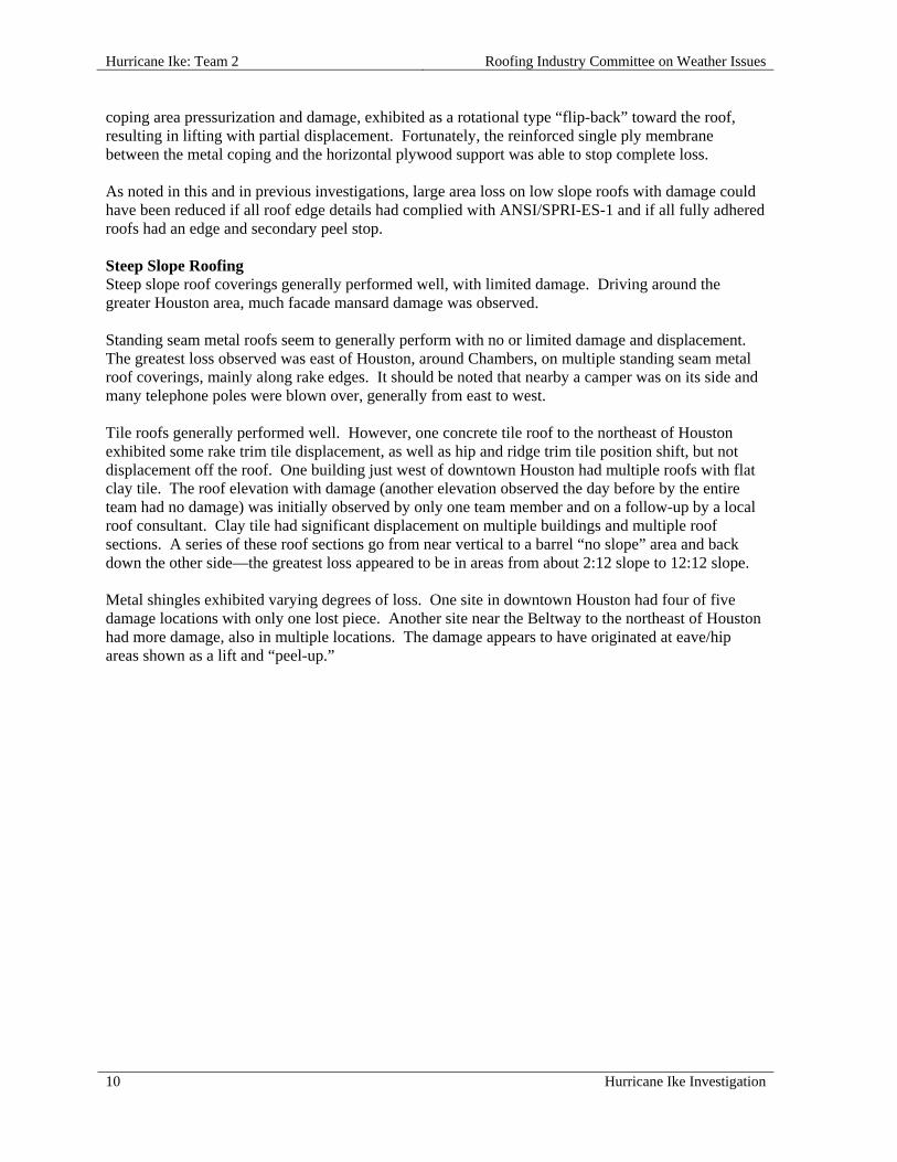
coping area pressurization and damage, exhibited as a rotational type “flip-back” toward the roof, resulting in lifting with partial displacement. Fortunately, the reinforced single ply membrane between the metal coping and the horizontal plywood support was able to stop complete loss. As noted in this and in previous investigations, large area loss on low slope roofs with damage could have been reduced if all roof edge details had complied with ANSI/SPRI-ES-1 and if all fully adhered roofs had an edge and secondary peel stop. Steep Slope Roofing Steep slope roof coverings generally performed well, with limited damage. Driving around the greater Houston area, much facade mansard damage was observed. Standing seam metal roofs seem to generally perform with no or limited damage and displacement. The greatest loss observed was east of Houston, around Chambers, on multiple standing seam metal roof coverings, mainly along rake edges. It should be noted that nearby a camper was on its side and many telephone poles were blown over, generally from east to west. Tile roofs generally performed well. However, one concrete tile roof to the northeast of Houston exhibited some rake trim tile displacement, as well as hip and ridge trim tile position shift, but not displacement off the roof. One building just west of downtown Houston had multiple roofs with flat clay tile. The roof elevation with damage (another elevation observed the day before by the entire team had no damage) was initially observed by only one team member and on a follow-up by a local roof consultant. Clay tile had significant displacement on multiple buildings and multiple roof sections. A series of these roof sections go from near vertical to a barrel “no slope” area and back down the other side—the greatest loss appeared to be in areas from about 2:12 slope to 12:12 slope. Metal shingles exhibited varying degrees of loss. One site in downtown Houston had four of five damage locations with only one lost piece. Another site near the Beltway to the northeast of Houston had more damage, also in multiple locations. The damage appears to have originated at eave/hip areas shown as a lift and “peel-up.”
Roofing Industry Committee on Weather Issues Hurricane Ike: Team 2
Hurricane Ike Investigation 11
INDIVIDUAL ROOF REPORTS
2.01 Brookside Intermediate School, 3535 E FM 528, Friendswood, TX 77546
SITE COORDINATES—N29º 31' 14" W95º 9' 54"
WALL CONSTRUCTION—Brick face
ROOF OR EAVE HEIGHT—27 ft
PEAK HEIGHT—27 ft
BUILDING LENGTH—200 ft
BUILDING WIDTH—132 ft
RELATIVE BUILDING HEIGHT—Slightly taller than surroundings
WALL, WINDOW, LOUVER OR OTHER OPENINGS—0-5 %
NUMBER OF PENETRATIONS GREATER THAN 4 ft x 4 ft x 2 ft HIGH—2
YEAR BUILDING CONSTRUCTED—1994
BUILDING USAGE—Gymnasium
BUILDING EXPOSURE—B
BUILDING PRESSURIZED—No
ASCE 7 BASIC WIND SPEED—110 mph
ACTUAL WIND SPEED—90 mph
WIND SPEED AT ROOFTOP—75 mph
VELOCITY PRESSURE—14 psf
PRIMARY WIND DIRECTION—Cornering wind
ROOF SLOPE—Low Slope Roof
ROOF TYPE—Fully Adhered Single Ply
DECK—Cementitious Wood Fiber
INSULATION TYPE—Polystyrene Foam
INSULATION THICKNESS—3-3/4 in.
INSULATION ATTACHMENT—Asphalt
MEMBRANE—EPDM
MEMBRANE ATTACHED TO—Wood Fiber
ATTACHED WITH—Bonding adhesive
SURFACE—Black
PERCENT OF DAMAGE—100%
DAMAGE INITIATION—Edge metal detachment resulted in separation of membrane and insulation layers of the roof assembly.

Hurricane Ike: Team 2 Roofing Industry Committee on Weather Issues
12 Hurricane Ike Investigation
DESCRIBE DAMAGE—The 45 mil, reinforced EPDM membrane was mostly detached from the roof by a northwest cornering wind. In the interior, the gymnasium floor buckled from water exposure. This building was classified as exposure B to the west and north, and exposure C from the northeast.
ROOF DAMAGE APPEARED TO BE CAUSED BY:
1. The 4 in. thick, 4 ft x 4 ft EPS foam insulation boards were partially adhered with asphalt to cement-fiber deck panels. A rough deck surface combined with stiff EPS board prevented a solid and continuous adhesive bond.
2. The ½ in. wood fiber cover board was partially adhered with asphalt to the EPS, and that bond failed.
3. The metal edge cleat was fastened with nails that were rusted. The cleat had a 7-1/2 in. vertical dimension and was fastened 2-3/4 in. down from the horizontal to vertical angle break using fasteners (1-1/4 in. roofing nails) spaced 25 in. - 35 in. o.c. on the vertical surface and 8 in. – 13 in. on the horizontal surface.
PHOTOGRAPHS OF ROOF DAMAGE
2.01-1. A debris field extended nearly a half mile south- southeast from the building.
2.01-2. 90% of roof assembly was displaced.

Roofing Industry Committee on Weather Issues Hurricane Ike: Team 2
Hurricane Ike Investigation 13
2.01-3. Aerial photo showing overview of roof damage.
2.01-4. View of displaced edge metal at west side and northwest corner.
2.01-5. Photo shows 1/2 in. wood fiber cover board. 2.01-6. Primary roof insulation consisted of 4 in. expanded polystyrene.
2.01-7. Fastener spacing for this edge metal was 25 in. o.c.
2.01-8. Edge metal fasteners were 1-1/4 in. roof nails with varying amounts of rust.

Hurricane Ike: Team 2 Roofing Industry Committee on Weather Issues
14 Hurricane Ike Investigation
2.01-9. Interior water damage included a buckled gymnasium floor.
2.01-10. This insulation board had too little asphalt adhesive for a strong bond.
2.02 Brookside Intermediate School, 3525 E FM 528, Friendswood, TX 77546
SITE COORDINATES—N29º 31' 09" W95º 9' 52"
WALL CONSTRUCTION—Brick face
ROOF OR EAVE HEIGHT—27 ft
PEAK HEIGHT—27 ft
BUILDING LENGTH—200 ft
BUILDING WIDTH—100 ft
RELATIVE BUILDING HEIGHT—Slightly taller than surroundings
NUMBER OF PENETRATIONS GREATER THAN 4 ft x 4 ft x 2 ft HIGH—2
YEAR BUILDING CONSTRUCTED—1994
BUILDING USAGE—School cafeteria / auditorium
BUILDING EXPOSURE—B
BUILDING PRESSURIZED—No
ASCE 7 BASIC WIND SPEED—110 mph
ACTUAL WIND SPEED—90 mph
WIND SPEED AT ROOFTOP—75 mph
VELOCITY PRESSURE—14 psf
PRIMARY WIND DIRECTION—Cornering wind
ROOF SLOPE—Low Slope Roof
ROOF TYPE—Mechanically Attached Single Ply
DECK—Metal
Roofing Industry Committee on Weather Issues Hurricane Ike: Team 2
Hurricane Ike Investigation 15
INSULATION TYPE—Polystyrene Foam
MEMBRANE—EPDM
MEMBRANE ATTACHED TO—Metal Deck
ATTACHMENT—Perimeter enhancement
ATTACHED WITH—Bonding adhesive
SURFACE—Black
PLATE SIZE—3 in.
FASTENER ROW SPACING—10 ft
FASTENER SPACING—5-1/2 in. - 9 in.
PERIMETER ENHANCEMENT—4-1/2 ft
PERCENT OF DAMAGE—>0<10%
DAMAGE INITIATION—Metal edge lifted and disengaged from cleat.
DESCRIBE DAMAGE—Metal edge at the west-northwest corner had isolated disengagement from cleats. The cleat had lifted on the long side (east-northeast) edge of the roof. The membrane remained in place with no damage, although some interior leakage caused damage to ceiling tiles.
ROOF DAMAGE APPEARED TO BE CAUSED BY:
1. Corroded fasteners with deteriorated holding power.
MISCELLANEOUS NOTES:
1. Roof system consisted of 10 ft wide sheets of EPDM sheet fastened 5-1/2 in. - 9 in. o.c.;
2. Seams had been repaired with an additional tape cover;
3. EPDM starter course was a 5 ft wide sheet terminated at 5 ft from the edge;
4. Second row of fasteners was 10 ft from first row at 15 ft from the perimeter;
5. Building was exposure B to the west and north; exposure C from the northeast.

Hurricane Ike: Team 2 Roofing Industry Committee on Weather Issues
16 Hurricane Ike Investigation
PHOTOGRAPHS OF ROOF DAMAGE
2.02-1. Overview of roof with damaged metal edge. 2.02-2. Closer view of disengaged metal edge and cleat.
2.02-3. Note that fasteners are relatively uniformly spaced.
2.02-4. Roofing nails used to secure the metal have significant rust.
2.02-5. Roof had additional fastening at 5 ft from roof edge.
2.02-6. Fasteners placed approximately 8 in. - 9 in. o.c.
Roofing Industry Committee on Weather Issues Hurricane Ike: Team 2
Hurricane Ike Investigation 17
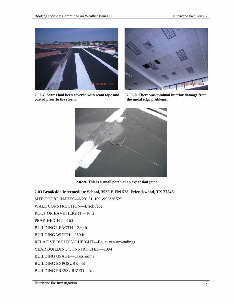
2.02-7. Seams had been covered with seam tape and coated prior to the storm.
2.02-8. There was minimal interior damage from the metal edge problems.
2.02-9. This is a small patch at an expansion joint. 2.03 Brookside Intermediate School, 3535 E FM 528, Friendswood, TX 77546
SITE COORDINATES—N29º 31' 10" W95º 9' 52"
WALL CONSTRUCTION—Brick face
ROOF OR EAVE HEIGHT—16 ft
PEAK HEIGHT—16 ft
BUILDING LENGTH—380 ft
BUILDING WIDTH—250 ft
RELATIVE BUILDING HEIGHT—Equal to surroundings
YEAR BUILDING CONSTRUCTED—1994
BUILDING USAGE—Classrooms
BUILDING EXPOSURE—B
BUILDING PRESSURIZED—No

Hurricane Ike: Team 2 Roofing Industry Committee on Weather Issues
18 Hurricane Ike Investigation
ASCE 7 BASIC WIND SPEED—120 mph
ACTUAL WIND SPEED—90 mph
WIND SPEED AT ROOFTOP—70 mph
VELOCITY PRESSURE—13 psf
PRIMARY WIND DIRECTION—Cornering wind
ROOF SLOPE—Low Slope Roof
ROOF TYPE—Mechanically Attached Single Ply
DECK—Metal T
TEARS #—1 large
INSULATION TYPE—Polystyrene Foam
MEMBRANE—EPDM
MEMBRANE ATTACHED TO—Metal Deck
ATTACHMENT—Perimeter enhancement
ATTACHED WITH—Bonding adhesive
SURFACE—Black
PERCENT OF DAMAGE—>0<10%
DAMAGE INITIATION—Metal edge lifted and disengaged from cleat, but remained in place.
DESCRIBE DAMAGE—A small area adjacent to the windward edge of the roof had lost its bond and opened up due to storm winds. This resulted in a leak in that area. With the exception of a large nearby tear the roof was intact and performing.
ROOF DAMAGE APPEARED TO BE CAUSED BY:
1. Loss of bond of membrane to the underlying “Russ strip.” This allowed storm winds to infiltrate, pressurize and tear the membrane.
MISCELLANEOUS NOTES:
1. Building was exposure B to the west and north, and exposure C from the northeast.

Roofing Industry Committee on Weather Issues Hurricane Ike: Team 2
Hurricane Ike Investigation 19
PHOTOGRAPHS OF ROOF DAMAGE
2.03-1. An overview of localized damage. 2.03-2. Edge metal was bonded with adhesive.
2.03-3. Loss of bond at roof edge caused tearing of the EPDM.
2.03-4. This photo shows torn membrane in an adjacent area.
2.03-5. Most of the roof assembly remained intact.

Hurricane Ike: Team 2 Roofing Industry Committee on Weather Issues
20 Hurricane Ike Investigation
2.04 Windsong Intermediate School, 2100 W Parkwood, Friendswood, TX 77546
SITE COORDINATES—N29° 29' 18" W95° 12' 54"
WALL CONSTRUCTION—Brick face
ROOF OR EAVE HEIGHT—14 ft
PEAK HEIGHT—15 ft
BUILDING LENGTH—380 ft
BUILDING WIDTH—186 ft
RELATIVE BUILDING HEIGHT—Shorter than surroundings
WALL, WINDOW, LOUVER OR OTHER OPENINGS—0-5 %
NUMBER OF PENETRATIONS GREATER THAN 4 ft x 4 ft x 2 ft HIGH—6
YEAR BUILDING CONSTRUCTED—1999
BUILDING USAGE—School classrooms
BUILDING EXPOSURE—B
BUILDING PRESSURIZED—No
ASCE 7 BASIC WIND SPEED—110 mph
ACTUAL WIND SPEED—90 mph
WIND SPEED AT ROOFTOP—69 mph
VELOCITY PRESSURE—12 psf
PRIMARY WIND DIRECTION—Cornering wind
ROOF SLOPE—Low Slope Roof
ROOF TYPE—Mechanically Attached Single Ply
DECK—Metal
TEARS #—11
INSULATION TYPE—Polyisocyanurate Foam
INSULATION ATTACHMENT—Screws & plates
MEMBRANE—PVC
MEMBRANE ATTACHED TO—Metal Deck
ATTACHMENT—Perimeter enhancement
SURFACE—White
FASTENER ROW SPACING—5 ft
FASTENER SPACING—9 in. - 14 in.
PERCENT OF DAMAGE—>0<10%
DAMAGE INITIATION—Originated at the northwest corner of the building.

Roofing Industry Committee on Weather Issues Hurricane Ike: Team 2
Hurricane Ike Investigation 21
DESCRIBE DAMAGE—This mechanically attached reinforced PVC single ply membrane (perimeter and corner enhancement) had disengaged from the upper gymnasium roof and rolled and tumbled across the lower elevation roofs, creating a few small tears/punctures. There were "skip marks" (surface abrasions) from the flashing; edge metal came off and airborne metal debris cut into the roof.
MISCELLANEOUS NOTES:
1. This building was classified as exposure B to the west and north, and exposure C to the northeast.
PHOTOGRAPHS OF ROOF DAMAGE
2.04-1. Aerial photo of the roof. 2.04-2. Excellent slope was noted on this roof, with no membrane detachment.
2.04-3. This low elevation roof had eleven cuts and/ or tears.
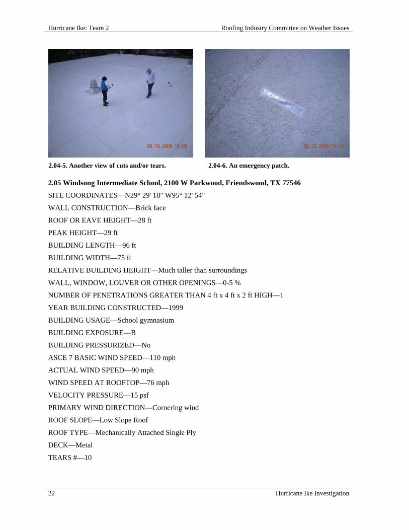
2.04-4. Another view of cuts and/or tears.
Hurricane Ike: Team 2 Roofing Industry Committee on Weather Issues
22 Hurricane Ike Investigation
2.04-5. Another view of cuts and/or tears. 2.04-6. An emergency patch. 2.05 Windsong Intermediate School, 2100 W Parkwood, Friendswood, TX 77546
SITE COORDINATES—N29° 29' 18" W95° 12' 54"
WALL CONSTRUCTION—Brick face
ROOF OR EAVE HEIGHT—28 ft
PEAK HEIGHT—29 ft
BUILDING LENGTH—96 ft
BUILDING WIDTH—75 ft
RELATIVE BUILDING HEIGHT—Much taller than surroundings
WALL, WINDOW, LOUVER OR OTHER OPENINGS—0-5 %
NUMBER OF PENETRATIONS GREATER THAN 4 ft x 4 ft x 2 ft HIGH—1
YEAR BUILDING CONSTRUCTED—1999
BUILDING USAGE—School gymnasium
BUILDING EXPOSURE—B
BUILDING PRESSURIZED—No
ASCE 7 BASIC WIND SPEED—110 mph
ACTUAL WIND SPEED—90 mph
WIND SPEED AT ROOFTOP—76 mph
VELOCITY PRESSURE—15 psf
PRIMARY WIND DIRECTION—Cornering wind
ROOF SLOPE—Low Slope Roof
ROOF TYPE—Mechanically Attached Single Ply
DECK—Metal
TEARS #—10

Roofing Industry Committee on Weather Issues Hurricane Ike: Team 2
Hurricane Ike Investigation 23
INSULATION ATTACHMENT—Screws & plates
MEMBRANE—PVC
MEMBRANE ATTACHED TO—Metal Deck
ATTACHMENT—Perimeter enhancement
SURFACE—White
FASTENER ROW SPACING—5 ft
FASTENER SPACING—9 in. - 14 in.
PERCENT OF DAMAGE—>0<10%
DAMAGE INITIATION—Metal edge detachment, cuts, and punctures led to tears in membrane.
DESCRIBE DAMAGE—A mechanically attached, reinforced PVC single ply membrane disengaged from an upper gymnasium roof and blew across lower elevation roofs. This created a few small tears and punctures. Damage included “skip marks” (abrasions) from flashing, and cuts caused by airborne edge metal and other metal debris.
ROOF DAMAGE APPEARED TO BE CAUSED BY:
1. Loss of perimeter cleats allowed pressurized air into roof assembly through space behind cleats;
2. Cleat fastener type, size, and placement appeared inadequate;
3. Corroded fasteners may have led to less holding power (cleats).
MISCELLANEOUS NOTES:
1. Metal fastener placement was 9 in. - 14 in. o.c.;
2. Building was exposure B to the west and north, and exposure C from the northeast.
PHOTOGRAPHS OF ROOF DAMAGE
2.05-1. Aerial view of school shows all roofs investigated.
2.05-2. An example of metal edge blow-off on the windward corner of the highest roof.

Hurricane Ike: Team 2 Roofing Industry Committee on Weather Issues
24 Hurricane Ike Investigation
2.05-3. Metal edge trim was found at various locations on the ground.
2.05-4. This 8 in. cleat had fasteners approximately 2-1/2 in. from the upper edge.
2.05-5. Tears in the PVC appear to have been created by detached metal edge.
2.05-6. The roof system was installed with additional perimeter fastening using half sheets.
2.05-7. Some cleats were missing along this edge; note that air can infiltrate behind cleat. Also note high position of nail at upper right.
2.05-8. Another view shows that cleat is missing, allowing air infiltration behind cleat position.
Roofing Industry Committee on Weather Issues Hurricane Ike: Team 2
Hurricane Ike Investigation 25
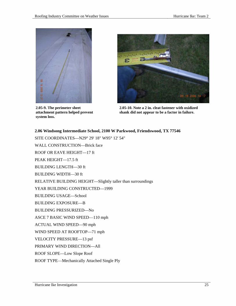
2.05-9. The perimeter sheet attachment pattern helped prevent system loss.
2.05-10. Note a 2 in. cleat fastener with oxidized shank did not appear to be a factor in failure.
2.06 Windsong Intermediate School, 2100 W Parkwood, Friendswood, TX 77546
SITE COORDINATES—N29° 29' 18" W95° 12' 54"
WALL CONSTRUCTION—Brick face
ROOF OR EAVE HEIGHT—17 ft
PEAK HEIGHT—17.5 ft
BUILDING LENGTH—30 ft
BUILDING WIDTH—30 ft
RELATIVE BUILDING HEIGHT—Slightly taller than surroundings
YEAR BUILDING CONSTRUCTED—1999
BUILDING USAGE—School
BUILDING EXPOSURE—B
BUILDING PRESSURIZED—No
ASCE 7 BASIC WIND SPEED—110 mph
ACTUAL WIND SPEED—90 mph
WIND SPEED AT ROOFTOP—71 mph
VELOCITY PRESSURE—13 psf
PRIMARY WIND DIRECTION—All
ROOF SLOPE—Low Slope Roof
ROOF TYPE—Mechanically Attached Single Ply

Hurricane Ike: Team 2 Roofing Industry Committee on Weather Issues
26 Hurricane Ike Investigation
DECK—Metal
TEARS #—9
MEMBRANE—PVC
MEMBRANE ATTACHED TO—Metal Deck
ATTACHMENT—Perimeter enhancement
SURFACE—White
FASTENER ROW SPACING—5 ft
FASTENER SPACING—1 ft
PERCENT OF DAMAGE—>0<10%
DAMAGE INITIATION—Disengagement and detachment of metal edge from one roof led to damage on a lower roof of the same building.
DESCRIBE DAMAGE—This roof was relatively undamaged except for multiple cuts in the single ply membrane.
ROOF DAMAGE APPEARED TO BE CAUSED BY:
1. Pieces of metal edge flashing that blew off of an upper roof section and across this roof, cut the single ply membrane in several places.
MISCELLANEOUS NOTES:
1. This is section two of the school roof; 20 ft above grade with one skylight.
PHOTOGRAPHS OF ROOF DAMAGE
2.06-1. The one puncture on this roof was from metal edge flashing on the upper gymnasium roof to the north.
2.06-2. A temporary repair from a cut or tear is visible at left.
2.07 Windsong Intermediate School, 2100 W Parkwood, Friendswood, TX 77546
SITE COORDINATES—N29° 29' 18" W95° 12' 54"
WALL CONSTRUCTION—Brick face
Roofing Industry Committee on Weather Issues Hurricane Ike: Team 2
Hurricane Ike Investigation 27
ROOF OR EAVE HEIGHT—24 ft
PEAK HEIGHT—24 ft
BUILDING LENGTH—73 ft
BUILDING WIDTH—63 ft
RELATIVE BUILDING HEIGHT—Slightly taller than surroundings
WALL, WINDOW, LOUVER OR OTHER OPENINGS—0-5 %
YEAR BUILDING CONSTRUCTED—1999
BUILDING USAGE—School
BUILDING EXPOSURE—B
BUILDING PRESSURIZED—No
ASCE 7 BASIC WIND SPEED—110 mph
ACTUAL WIND SPEED—90 mph
WIND SPEED AT ROOFTOP—74 mph
VELOCITY PRESSURE—14 psf
PRIMARY WIND DIRECTION—All
ROOF SLOPE—Low Slope Roof
ROOF TYPE—Mechanically Attached Single Ply
DECK—Metal
MEMBRANE—PVC
MEMBRANE ATTACHED TO—Metal Deck
ATTACHMENT—Perimeter enhancement
SURFACE—White
FASTENER ROW SPACING—5 ft
FASTENER SPACING—1 ft
PERCENT OF DAMAGE—>0<10%
DAMAGE INITIATION—Metal was deflected outward due to pressure from strong winds.
DESCRIBE DAMAGE—This roof was relatively undamaged. Sheet metal edge flashing was bent slightly and there was a slight billow in the flashing on the southwest side. There were no leaks or other damage.
ROOF DAMAGE APPEARED TO BE CAUSED BY:
1. Minor damage was due to pressure from strong winds.
Hurricane Ike: Team 2 Roofing Industry Committee on Weather Issues
28 Hurricane Ike Investigation
PHOTOGRAPHS OF ROOF DAMAGE
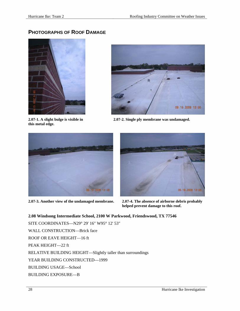
2.07-1. A slight bulge is visible in this metal edge.
2.07-2. Single ply membrane was undamaged.
2.07-3. Another view of the undamaged membrane. 2.07-4. The absence of airborne debris probably helped prevent damage to this roof.
2.08 Windsong Intermediate School, 2100 W Parkwood, Friendswood, TX 77546
SITE COORDINATES—N29° 29' 16" W95° 12' 53"
WALL CONSTRUCTION—Brick face
ROOF OR EAVE HEIGHT—16 ft
PEAK HEIGHT—22 ft
RELATIVE BUILDING HEIGHT—Slightly taller than surroundings
YEAR BUILDING CONSTRUCTED—1999
BUILDING USAGE—School
BUILDING EXPOSURE—B
Roofing Industry Committee on Weather Issues Hurricane Ike: Team 2
Hurricane Ike Investigation 29
BUILDING PRESSURIZED—No
ASCE 7 BASIC WIND SPEED—110 mph
ACTUAL WIND SPEED—90 mph
WIND SPEED AT ROOFTOP—73 mph
VELOCITY PRESSURE—14 psf
PRIMARY WIND DIRECTION—All
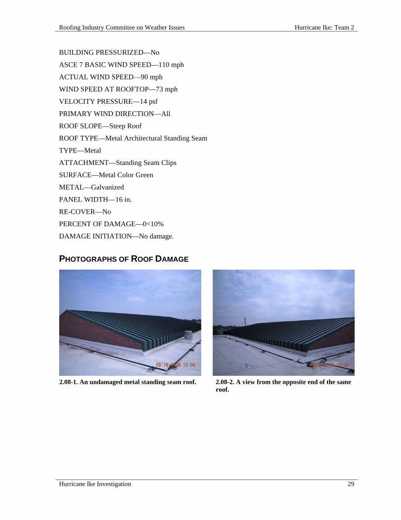
ROOF SLOPE—Steep Roof
ROOF TYPE—Metal Architectural Standing Seam
TYPE—Metal
ATTACHMENT—Standing Seam Clips
SURFACE—Metal Color Green
METAL—Galvanized
PANEL WIDTH—16 in.
RE-COVER—No
PERCENT OF DAMAGE—0<10%
DAMAGE INITIATION—No damage.
PHOTOGRAPHS OF ROOF DAMAGE
2.08-1. An undamaged metal standing seam roof.
2.08-2. A view from the opposite end of the same roof.
Hurricane Ike: Team 2 Roofing Industry Committee on Weather Issues
30 Hurricane Ike Investigation
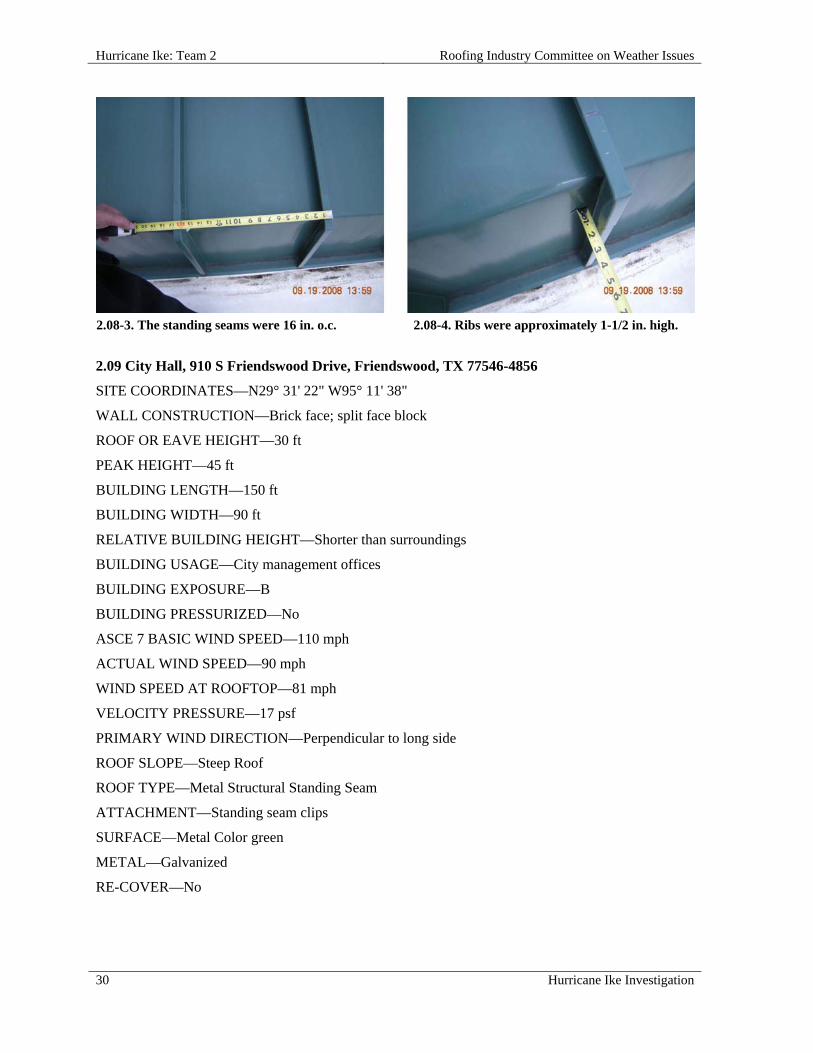
2.08-3. The standing seams were 16 in. o.c. 2.08-4. Ribs were approximately 1-1/2 in. high.
2.09 City Hall, 910 S Friendswood Drive, Friendswood, TX 77546-4856
SITE COORDINATES—N29° 31' 22" W95° 11' 38"
WALL CONSTRUCTION—Brick face; split face block
ROOF OR EAVE HEIGHT—30 ft
PEAK HEIGHT—45 ft
BUILDING LENGTH—150 ft
BUILDING WIDTH—90 ft
RELATIVE BUILDING HEIGHT—Shorter than surroundings
BUILDING USAGE—City management offices
BUILDING EXPOSURE—B
BUILDING PRESSURIZED—No
ASCE 7 BASIC WIND SPEED—110 mph
ACTUAL WIND SPEED—90 mph
WIND SPEED AT ROOFTOP—81 mph
VELOCITY PRESSURE—17 psf
PRIMARY WIND DIRECTION—Perpendicular to long side
ROOF SLOPE—Steep Roof
ROOF TYPE—Metal Structural Standing Seam
ATTACHMENT—Standing seam clips
SURFACE—Metal Color green
METAL—Galvanized
RE-COVER—No

Roofing Industry Committee on Weather Issues Hurricane Ike: Team 2
Hurricane Ike Investigation 31
PERCENT OF DAMAGE—>0<10%
DAMAGE INITIATION—Damage began and ended at the rake edge metal trim.
DESCRIBE DAMAGE—This building had very little damage. A small section of fascia was disengaged but not displaced.
ROOF DAMAGE APPEARED TO BE CAUSED BY:
1. Pressure from strong winds infiltrated the metal edge, causing it to disengage from the wall.
MISCELLANEOUS NOTES:
1. Owners, the City of Friendswood, secured the building with steel shutters;
2. Entry and back of building were protected by Kevlar type material secured with eyehooks and bolts into concrete;
3. Preparations also included secondary protection for record files.
PHOTOGRAPHS OF ROOF DAMAGE
2.09-1. Aerial view of Friendswood City Hall. 2.09-2. Metal shutters were installed to protect
windows.

Hurricane Ike: Team 2 Roofing Industry Committee on Weather Issues
32 Hurricane Ike Investigation
2.09-3. Over the front of the building was a raised section with a slightly damaged rake edge.
2.09-4. A closer look at the damaged edge.
2.10 Mitch Foster DDS, 17150 El Camino Real, Webster, TX 77058
SITE COORDINATES—N29° 29' 16" W95° 12' 53"
WALL CONSTRUCTION—Brick face
ROOF OR EAVE HEIGHT—12 ft
PEAK HEIGHT—25 ft
BUILDING LENGTH—120 ft
BUILDING WIDTH—120 ft
RELATIVE BUILDING HEIGHT—Slightly taller than surroundings
WALL, WINDOW, LOUVER OR OTHER OPENINGS—0-5 %
NUMBER OF PENETRATIONS GREATER THAN 4 ft x 4 ft x 2 ft HIGH—3
YEAR BUILDING CONSTRUCTED—1975
BUILDING USAGE—Dental offices
BUILDING EXPOSURE—B
BUILDING PRESSURIZED—Yes
ASCE 7 BASIC WIND SPEED—110 mph
ACTUAL WIND SPEED—90 mph
WIND SPEED AT ROOFTOP—74 mph
VELOCITY PRESSURE—14 psf
PRIMARY WIND DIRECTION—Perpendicular to short side
ROOF SLOPE—Low Slope Roof
ROOF TYPE—Modified Bitumen

Roofing Industry Committee on Weather Issues Hurricane Ike: Team 2
Hurricane Ike Investigation 33
DECK—Metal
MEMBRANE ATTACHED TO—Lightweight Insulating Concrete
ATTACHED WITH—Split-shank fasteners
SURFACE—Granules
PERCENT OF DAMAGE—100%
DAMAGE INITIATION—Blow-off of field membrane following fastener pull-out.
DESCRIBE DAMAGE—The entire 10,600 sq ft roof cover and three skylights were displaced, although the metal edge remained in place. Surrounding roofs were not damaged, and it appeared to be a relatively low wind speed area, likely well below 90 mph.
ROOF DAMAGE APPEARED TO BE CAUSED BY:
1. Quantity of base sheet fasteners was less than expected (an average of one per 2.6 sq ft) and they were not uniformly spaced;
2. Most fasteners pulled through the base sheet and fasteners pulled free of the LWIC i.e., a double failure;
3. Some of the split-shank fasteners remained in a closed position, meaning they never opened up to engage the LWIC for holding power.
MISCELLANEOUS NOTES:
1. The winds appeared to be from northwest to southeast;
2. Some displaced material was found in a tree to the east-southeast;
3. Roof was an unusual design with 3:12 slope for most areas, and covered with LWIC over a steel deck;
4. The membrane was a mineral surfaced MB cap sheet torch-applied to a built-up roof membrane (BUR) mopped to a nailed glass fiber base ply.
PHOTOGRAPHS OF ROOF DAMAGE
2.10-1. Aerial view of the Mitch Foster Building - the only one in the area with damage.
2.10-2. Part of the roof membrane was blown to the ground.

Hurricane Ike: Team 2 Roofing Industry Committee on Weather Issues
34 Hurricane Ike Investigation
2.10-3. Some of the membrane wound up in this tree, along with attached skylights.
2.10-4. Note the limited and uneven fastener pattern.
2.10-5. Split-shank fasteners have to open up to engage; some remained closed.
2.10-6. This fastener, in comparison with photo 2.10-5, was open and engaged.
2.10-7. Temporary repairs can be seen on this roof section.
2.10-8. Lightweight concrete decking in this photo was broken and detached.

Roofing Industry Committee on Weather Issues Hurricane Ike: Team 2
Hurricane Ike Investigation 35
2.11 Anahuac Intermediate School Band Choir, 500 Stowell, Anahuac, TX 77520
SITE COORDINATES—N29° 46' 12" W94° 40' 47"
WALL CONSTRUCTION—Tilt-up Concrete
ROOF OR EAVE HEIGHT—27 ft
PEAK HEIGHT—27 ft
BUILDING LENGTH—120 ft
BUILDING WIDTH—70 ft
OVERHANG LENGTH—70 ft
OVERHANG WIDTH—4 in.
RELATIVE BUILDING HEIGHT—Slightly taller than surroundings
YEAR BUILDING CONSTRUCTED—1975
BUILDING USAGE—School band & choir
BUILDING EXPOSURE—C
BUILDING PRESSURIZED—No
ASCE 7 BASIC WIND SPEED—110 mph
ACTUAL WIND SPEED—110 mph
WIND SPEED AT ROOFTOP—109 mph
VELOCITY PRESSURE—30 psf
PRIMARY WIND DIRECTION—Perpendicular to short side
ROOF SLOPE—Low Slope Roof
ROOF TYPE—Granular Surfaced BUR
DECK—Metal
INSULATION TYPE—Fesco Board
INSULATION THICKNESS—1 in. - 3 in.
INSULATION ATTACHMENT—Asphalt
MEMBRANE ATTACHED TO—Cover Board
ATTACHED WITH—Fully Adhered - mopped
PERCENT OF DAMAGE—>75 <100%
DAMAGE INITIATION—An overhanging gutter and fractured nailer provided a starting point for peel-back of this multi-ply membrane.

Hurricane Ike: Team 2 Roofing Industry Committee on Weather Issues
36 Hurricane Ike Investigation
DESCRIBE DAMAGE—Damage occurred over most of the roof, beginning at the east side and stopping short of the west edge. Damage was observed to metal edge, nailers, roof membrane, insulation, and even a small portion of steel deck. Built-up roof membrane (BUR) peeled away from the insulation layer, except at the windward edge where insulation was stripped down to the metal deck, which was also displaced.
ROOF DAMAGE APPEARED TO BE CAUSED BY:
1. Overhanging gutter may have created the rotating mechanism opportunity for wind pressure to cause the initial detachment of edge metal;
2. Metal edge flashing overhung the exterior wall, and although installed conservatively, the nailer pulled over the fasteners and started the progressive peel and displacement of the BUR.
MISCELLANEOUS NOTES:
1. Greatest exposure to wind was from the east, the primary wind direction of the storm in this area;
2. Membrane was a mineral surfaced MB cap sheet mopped to a BUR;
3. Insulation boards were tapered in three layers, varying in thickness (3/4 in.+½ in.+½ in.=1-3/4 in.) at edges and 6 in. at the ridge;
4. Perimeter nailer was bolted to joists at 6 ft o.c. with ¼ in. diameter bolts installed in an offset pattern, without washers at the heads;
5. Building was 33 years old.
PHOTOGRAPHS OF ROOF DAMAGE
2.11-1. Aerial view of the Band Choir Building. 2.11-2. Membrane peeled away from the
insulation and detached from the roof in most areas.

Roofing Industry Committee on Weather Issues Hurricane Ike: Team 2
Hurricane Ike Investigation 37
2.11-3. Roof membrane and insulation tore loose from the deck in this corner. Note rusted deck.
2.11-4. On the windward edge (south side), metal edge was nearly completely dislodged.
2.11-5. The underside of the membrane. 2.11-6. In addition to damage described in 2.11-2,
tapered insulation is visible.
2.11-7. Fascia metal was relatively wide. 2.11-8. Fastener locations can be seen on this piece
of detached membrane.

Hurricane Ike: Team 2 Roofing Industry Committee on Weather Issues
38 Hurricane Ike Investigation
2.11-9. This piece of metal cleat still has wood nailer attached.
2.11-10. Photo of gutter/cleat attachment is a good example of damage progression.
2.12 Anahuac Intermediate School Gymnasium, 500 Stowell, Anahuac, TX 77520
SITE COORDINATES—N29° 46' 13" W94° 40' 50"
WALL CONSTRUCTION—Brick veneer
ROOF OR EAVE HEIGHT—24 ft
PEAK HEIGHT—30 ft
BUILDING LENGTH—120 ft
BUILDING WIDTH—80 ft
OVERHANG LENGTH—80 ft
OVERHANG WIDTH—3 in.
RELATIVE BUILDING HEIGHT—Equal to surroundings
YEAR BUILDING CONSTRUCTED—1955
BUILDING USAGE—Gymnasium
BUILDING EXPOSURE—C
BUILDING PRESSURIZED—Yes
ASCE 7 BASIC WIND SPEED—110 mph
ACTUAL WIND SPEED—110 mph
WIND SPEED AT ROOFTOP—111 mph
VELOCITY PRESSURE—32 psf
PRIMARY WIND DIRECTION—Perpendicular to long side
ROOF SLOPE—Low Slope Roof

Roofing Industry Committee on Weather Issues Hurricane Ike: Team 2
Hurricane Ike Investigation 39
ROOF TYPE—Granular Surfaced BUR
DECK—Cementitious Wood Fiber
INSULATION TYPE—Fesco Board
INSULATION THICKNESS—1/2 in.
MEMBRANE ATTACHED TO—Lightweight Insulating Concrete
ATTACHED WITH—Fully Adhered - mopped
PERCENT OF DAMAGE—100%
DAMAGE INITIATION—It was difficult to determine the starting point, as the roof had been temporarily repaired.
DESCRIBE DAMAGE—The entire steep roof was displaced, and edge metal was missing from the windward side.
ROOF DAMAGE APPEARED TO BE CAUSED BY:
1. Base sheet fasteners pulled free of the deck, fasteners were rusted, and some appeared to be missing the hook/leg that engages cementitious decking;
2. Openings at the brick and rake edge juncture may be an indication that internal pressurization occurred.
MISCELLANEOUS NOTES:
1. Roof was covered with a 3-ply built-up roof membrane (BUR) mopped and fully adhered to a nailed, glass fiber SBS modified bituminous base sheet;
2. Deck was LWIC.
PHOTOGRAPHS OF ROOF DAMAGE
2.12-1. Distant view of a steep slope roof that has been displaced. The structure was temporarily covered.
2.12-2. A closer view of the roof.
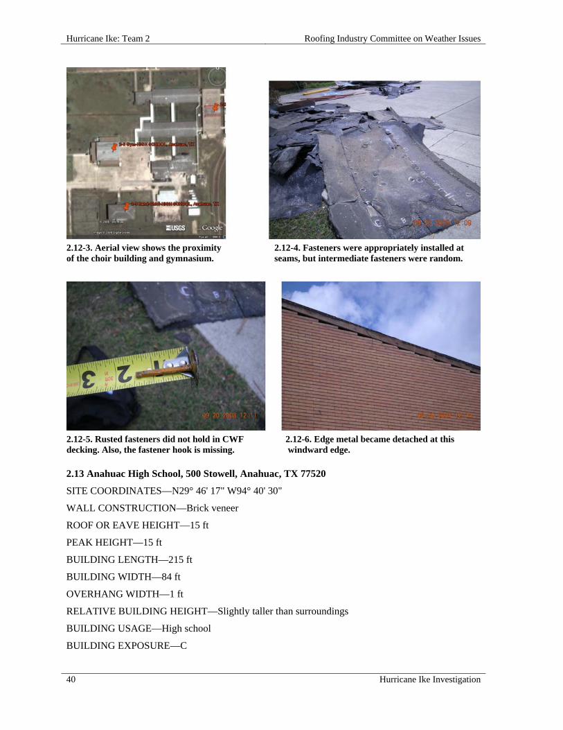
Hurricane Ike: Team 2 Roofing Industry Committee on Weather Issues
40 Hurricane Ike Investigation
2.12-3. Aerial view shows the proximity of the choir building and gymnasium.
2.12-4. Fasteners were appropriately installed at seams, but intermediate fasteners were random.
2.12-5. Rusted fasteners did not hold in CWF decking. Also, the fastener hook is missing.
2.12-6. Edge metal became detached at this windward edge.
2.13 Anahuac High School, 500 Stowell, Anahuac, TX 77520
SITE COORDINATES—N29° 46' 17" W94° 40' 30"
WALL CONSTRUCTION—Brick veneer
ROOF OR EAVE HEIGHT—15 ft
PEAK HEIGHT—15 ft
BUILDING LENGTH—215 ft
BUILDING WIDTH—84 ft
OVERHANG WIDTH—1 ft
RELATIVE BUILDING HEIGHT—Slightly taller than surroundings
BUILDING USAGE—High school
BUILDING EXPOSURE—C
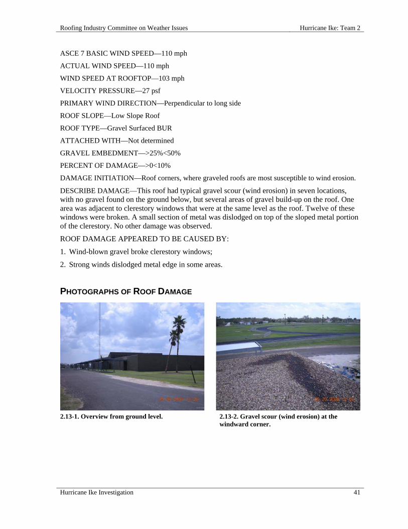
Roofing Industry Committee on Weather Issues Hurricane Ike: Team 2
Hurricane Ike Investigation 41
ASCE 7 BASIC WIND SPEED—110 mph
ACTUAL WIND SPEED—110 mph
WIND SPEED AT ROOFTOP—103 mph
VELOCITY PRESSURE—27 psf
PRIMARY WIND DIRECTION—Perpendicular to long side
ROOF SLOPE—Low Slope Roof
ROOF TYPE—Gravel Surfaced BUR
ATTACHED WITH—Not determined
GRAVEL EMBEDMENT—>25%<50%
PERCENT OF DAMAGE—>0<10%
DAMAGE INITIATION—Roof corners, where graveled roofs are most susceptible to wind erosion.
DESCRIBE DAMAGE—This roof had typical gravel scour (wind erosion) in seven locations, with no gravel found on the ground below, but several areas of gravel build-up on the roof. One area was adjacent to clerestory windows that were at the same level as the roof. Twelve of these windows were broken. A small section of metal was dislodged on top of the sloped metal portion of the clerestory. No other damage was observed.
ROOF DAMAGE APPEARED TO BE CAUSED BY:
1. Wind-blown gravel broke clerestory windows;
2. Strong winds dislodged metal edge in some areas.
PHOTOGRAPHS OF ROOF DAMAGE
2.13-1. Overview from ground level. 2.13-2. Gravel scour (wind erosion) at the
windward corner.

Hurricane Ike: Team 2 Roofing Industry Committee on Weather Issues
42 Hurricane Ike Investigation
2.13-3. Gravel scour left a dark trail of exposed asphalt next to a clerestory.
2.13-4. Gravel scour also occurred at this leeward corner.
2.13-5. The field of the roof was left undamaged. 2.13-6. Aggregate size was less than 1/2 in.
2.13-7. Broken windows were noted on this portion of the building.
2.13-8. Metal damage occurred in this area.
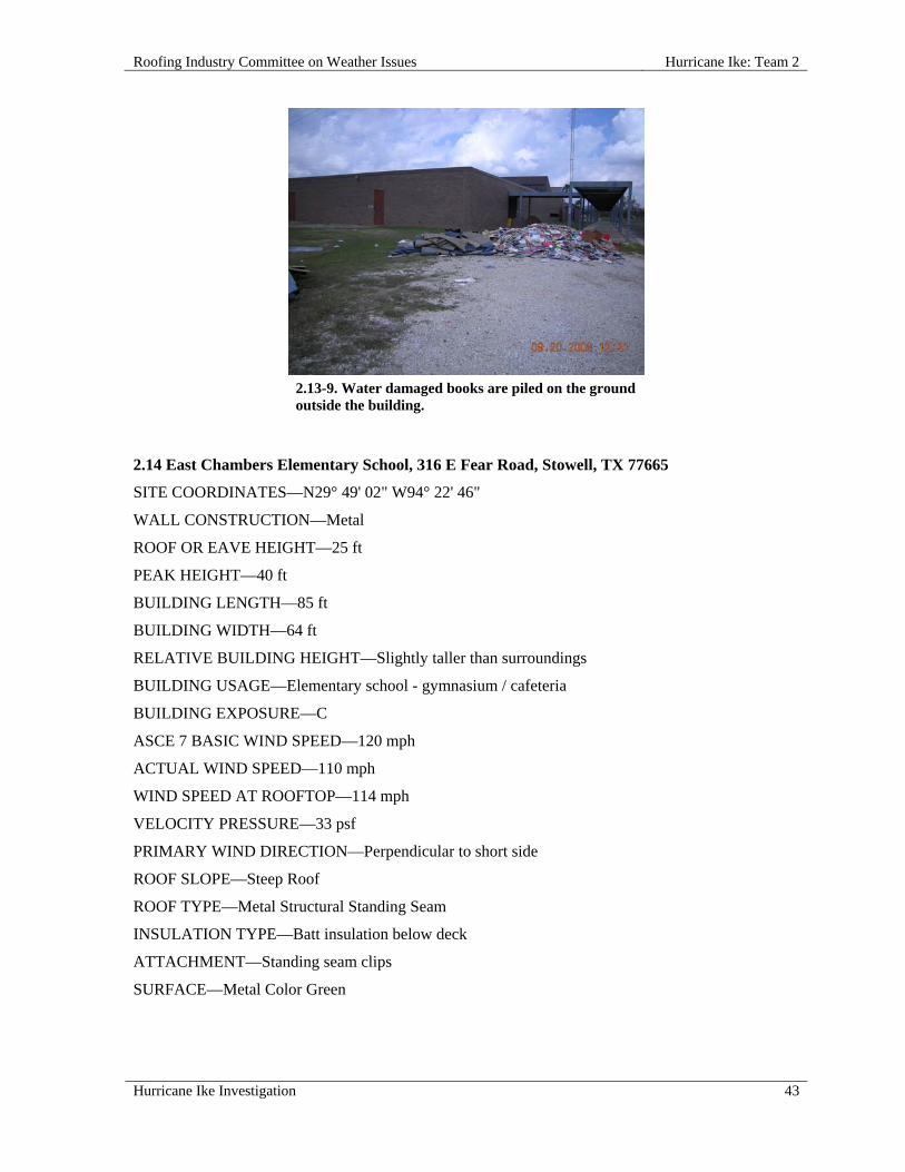
Roofing Industry Committee on Weather Issues Hurricane Ike: Team 2
Hurricane Ike Investigation 43
2.13-9. Water damaged books are piled on the ground
outside the building.
2.14 East Chambers Elementary School, 316 E Fear Road, Stowell, TX 77665
SITE COORDINATES—N29° 49' 02" W94° 22' 46"
WALL CONSTRUCTION—Metal
ROOF OR EAVE HEIGHT—25 ft
PEAK HEIGHT—40 ft
BUILDING LENGTH—85 ft
BUILDING WIDTH—64 ft
RELATIVE BUILDING HEIGHT—Slightly taller than surroundings
BUILDING USAGE—Elementary school - gymnasium / cafeteria
BUILDING EXPOSURE—C
ASCE 7 BASIC WIND SPEED—120 mph
ACTUAL WIND SPEED—110 mph
WIND SPEED AT ROOFTOP—114 mph
VELOCITY PRESSURE—33 psf
PRIMARY WIND DIRECTION—Perpendicular to short side
ROOF SLOPE—Steep Roof
ROOF TYPE—Metal Structural Standing Seam
INSULATION TYPE—Batt insulation below deck
ATTACHMENT—Standing seam clips
SURFACE—Metal Color Green

Hurricane Ike: Team 2 Roofing Industry Committee on Weather Issues
44 Hurricane Ike Investigation
METAL THICKNESS—22 gauge
PANEL WIDTH—18 in.
RE-COVER—No
PERCENT OF DAMAGE—>0<10%
DAMAGE INITIATION—Seams at perimeter rake edges disengaged, allowing panels to become pressurized.
DESCRIBE DAMAGE—The panel seams disengaged in the upwind corner, but no panels were displaced. Insulation protruded through the opened seams.
ROOF DAMAGE APPEARED TO BE CAUSED BY:
1. Strong winds caused rib disengagement at corners.
MISCELLANEOUS NOTES:
1. Metal roof consisted of site-rolled panels;
2. This is one of three sites in the same school district with damaged metal roofs.
PHOTOGRAPHS OF ROOF DAMAGE
2.14-1. Aerial view of site.
2.14-2. The east elevation standing seam disengaged and bowed upward.

Roofing Industry Committee on Weather Issues Hurricane Ike: Team 2
Hurricane Ike Investigation 45
2.14-3. The west elevation standing seam had disengagement and bowing issues similar to the east elevation (photo 2.14-2).
2.15 East Chambers High School, School Road, Winnie, TX 77665
SITE COORDINATES—N29° 48' 15" W94° 22' 58"
WALL CONSTRUCTION—Brick face
ROOF OR EAVE HEIGHT—26 ft
PEAK HEIGHT—32 ft
BUILDING LENGTH—200 ft
BUILDING WIDTH—50 ft
RELATIVE BUILDING HEIGHT—Equal to surroundings
BUILDING USAGE—Middle school maintenance building
BUILDING EXPOSURE—C
BUILDING PRESSURIZED—No
ASCE 7 BASIC WIND SPEED—120 mph
ACTUAL WIND SPEED—110 mph
WIND SPEED AT ROOFTOP—111 mph
VELOCITY PRESSURE—32 psf
PRIMARY WIND DIRECTION—Perpendicular to long side
ROOF SLOPE—Steep Roof
ROOF TYPE—Metal Structural Standing Seam
INSULATION TYPE—Batt insulation below deck
ATTACHMENT—Standing seam clips

Hurricane Ike: Team 2 Roofing Industry Committee on Weather Issues
46 Hurricane Ike Investigation
SURFACE—Metal Color green
METAL—Galvanized
METAL THICKNESS—22 gauge
PANEL WIDTH—18 in.
RE-COVER—No
PERCENT OF DAMAGE—>0<10%
DAMAGE INITIATION—Metal seams failed at windward corners.
DESCRIBE DAMAGE—Metal roofs had varying degrees of panel damage. Two metal panels were displaced from a section opposite the windward side.
ROOF DAMAGE APPEARED TO BE CAUSED BY:
1. Panel seams disengaged in the upwind corner, due to strong winds;
2. Insulation protruded through the opened seams.
MISCELLANEOUS NOTES:
1. Metal roof consisted of site-rolled panels;
2. This is the second of three sites in the same school district that had metal roof damage.
PHOTOGRAPHS OF ROOF DAMAGE
2.15-1. Aerial photo (middle building) shows one of three sites in this district with damaged metal roofs.
2.15-2. Another aerial photo of this site.

Roofing Industry Committee on Weather Issues Hurricane Ike: Team 2
Hurricane Ike Investigation 47
2.15-3. At the bottom of this photo, note missing metal panels.
2.15-4. No clips were found on these displaced panels.
2.15-5. Seam height was 2 in. 2.15-6. Metal panels were 16 in. wide.
2.16 East Chambers High School, 234 E Buccaneer Drive, Stowell, TX 77661
SITE COORDINATES—N29° 48' 19" W94° 22' 49"
WALL CONSTRUCTION—Brick face
ROOF OR EAVE HEIGHT—35 ft
PEAK HEIGHT—50 ft
PARAPET HEIGHT—20 ft
BUILDING LENGTH—108 ft + 300 ft
BUILDING WIDTH—100 ft + 85 ft
RELATIVE BUILDING HEIGHT—Equal to surroundings
BUILDING USAGE—High school
BUILDING EXPOSURE—C
BUILDING PRESSURIZED—Yes
ASCE 7 BASIC WIND SPEED—120 mph
Hurricane Ike: Team 2 Roofing Industry Committee on Weather Issues
48 Hurricane Ike Investigation
ACTUAL WIND SPEED—110 mph
WIND SPEED AT ROOFTOP—117 mph
VELOCITY PRESSURE—35 psf
PRIMARY WIND DIRECTION—Perpendicular to short side
ROOF SLOPE—Steep Roof
ROOF TYPE—Metal Architectural Standing Seam
INSULATION TYPE—Batt insulation below deck
ATTACHMENT—Standing Seam Clips
SURFACE—Metal Color green
METAL THICKNESS—22 gauge
PANEL WIDTH—18 in.
FASTENER ROW SPACING—Floating cup
RE-COVER—No
PERCENT OF DAMAGE—>10<25%
DAMAGE INITIATION—Panel seams disengaged from clips on windward sides.
DESCRIBE DAMAGE—This steep metal roof had several panels missing from the windward side and seams that were open on the leeward side on portions of each of two buildings.
ROOF DAMAGE APPEARED TO BE CAUSED BY:
1. Seam failure (disengagement) due to high winds.
MISCELLANEOUS NOTES:
1. Roof was installed with site-rolled metal;
2. Repairs were underway at time of inspection.
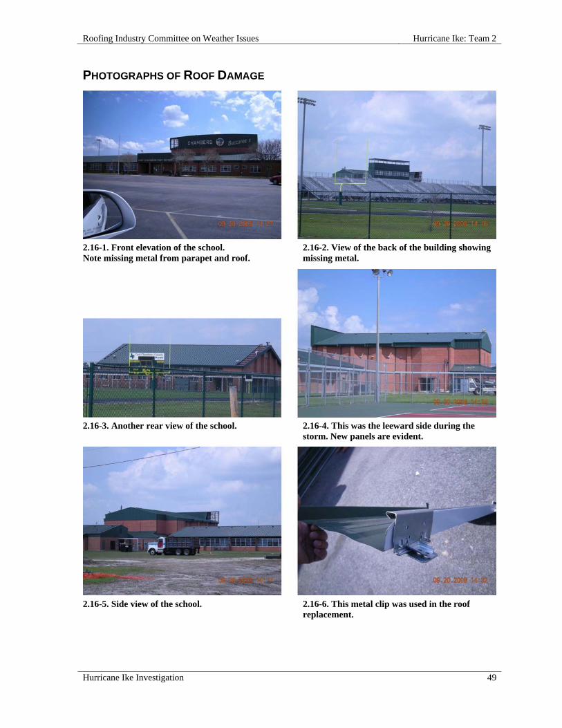
Roofing Industry Committee on Weather Issues Hurricane Ike: Team 2
Hurricane Ike Investigation 49
PHOTOGRAPHS OF ROOF DAMAGE
2.16-1. Front elevation of the school. Note missing metal from parapet and roof.
2.16-2. View of the back of the building showing missing metal.
2.16-3. Another rear view of the school. 2.16-4. This was the leeward side during the
storm. New panels are evident.
2.16-5. Side view of the school.
2.16-6. This metal clip was used in the roof replacement.

Hurricane Ike: Team 2 Roofing Industry Committee on Weather Issues
50 Hurricane Ike Investigation
2.16-7. View of metal readied for roof replacement. 2.16-8. Aerial view of Chambers Campus; upper
label is the high school.
2.16-9. This photo shows the parapet.
2.17 CVS Pharmacy, I-90, Liberty, TX 77575
SITE COORDINATES—N30° 03' 25" W90° 47' 46"
WALL CONSTRUCTION—Concrete block and EIFS
ROOF OR EAVE HEIGHT—14 ft
PEAK HEIGHT—17 ft
PARAPET HEIGHT—6 in. - 48 in.
BUILDING LENGTH—150 ft
BUILDING WIDTH—110 ft
OVERHANG LENGTH—1 ft
OVERHANG WIDTH—1 ft
RELATIVE BUILDING HEIGHT—Equal to surroundings
YEAR BUILDING CONSTRUCTED—2007
BUILDING CODE AT TIME OF CONSTRUCTION—IBC 2003
BUILDING USAGE—Retail
BUILDING EXPOSURE—B
Roofing Industry Committee on Weather Issues Hurricane Ike: Team 2
Hurricane Ike Investigation 51
ASCE 7 BASIC WIND SPEED—110 mph
ACTUAL WIND SPEED—100 mph
WIND SPEED AT ROOFTOP—78 mph
VELOCITY PRESSURE—16 psf
PRIMARY WIND DIRECTION—Cornering wind
ROOF SLOPE—Low Slope Roof
ROOF TYPE—Fully Adhered Single Ply
DECK—Metal
INSULATION TYPE—Polyisocyanurate Foam
INSULATION THICKNESS—2-1/4 in.
INSULATION ATTACHMENT—Screws & plates
MEMBRANE—TPO
MEMBRANE ATTACHED TO—Insulation
ATTACHED WITH—Bonding adhesive
SURFACE—White
PERCENT OF DAMAGE—>0<10%
DAMAGE INITIATION—Failure of edge metal and plywood coping nailer.
DESCRIBE DAMAGE—Edge metal and plywood nailer were dislodged on two parapet walls, allowing coping to be blown backward toward the roof. There was no damage to the roof membrane or to the contents of the building.
ROOF DAMAGE APPEARED TO BE CAUSED BY:
1. Poor installation and improper materials led to failure of nailer and coping on parapets;
2. Plywood coping nailer was attached with six drywall screws per 8 ft; the wind force leveraged the overhanging fascia and overturned it.
MISCELLANEOUS NOTES:
1. This typical design for CVS stores has an overhanging fluorescent light tube beneath the parapet top. This light is hidden by fascia metal connected to a double layer of ¾ in. plywood face nailed to a 2 in. x 8 in. wood nailer on top of the CMU wall.
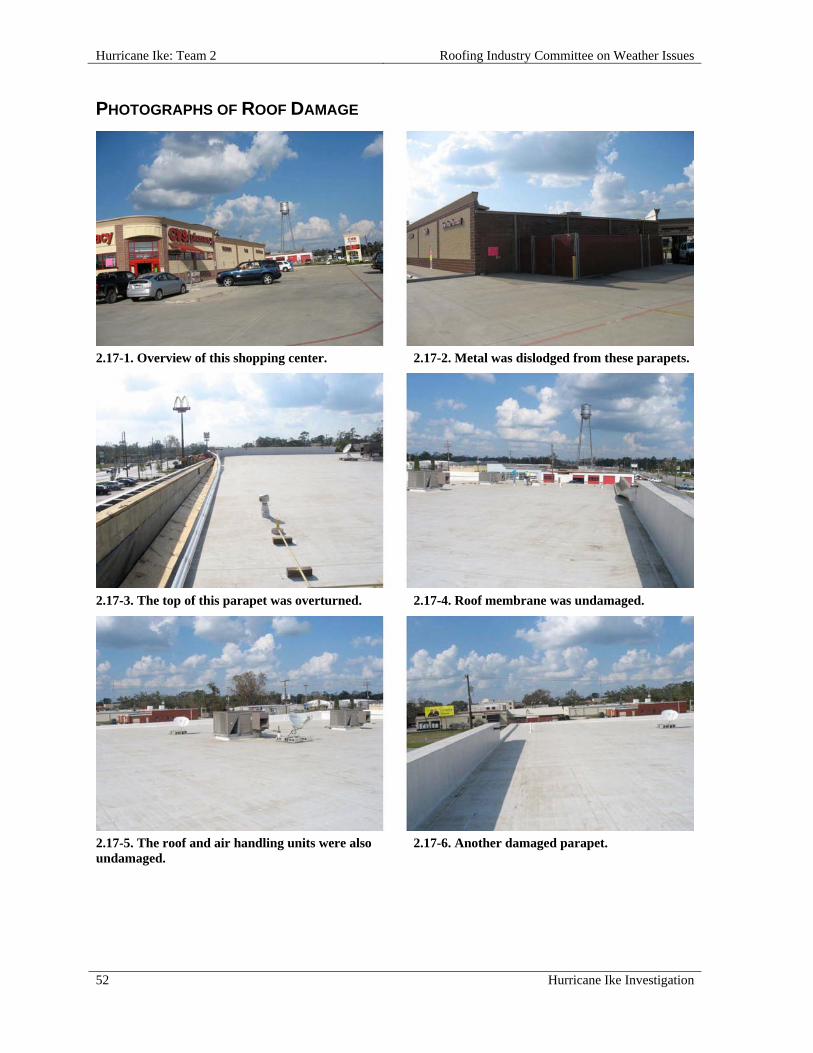
Hurricane Ike: Team 2 Roofing Industry Committee on Weather Issues
52 Hurricane Ike Investigation
PHOTOGRAPHS OF ROOF DAMAGE
2.17-1. Overview of this shopping center. 2.17-2. Metal was dislodged from these parapets.
2.17-3. The top of this parapet was overturned. 2.17-4. Roof membrane was undamaged.
2.17-5. The roof and air handling units were also undamaged.
2.17-6. Another damaged parapet.

Roofing Industry Committee on Weather Issues Hurricane Ike: Team 2
Hurricane Ike Investigation 53
2.17-7. On this damaged parapet, wind forced the coping system over the parapet and back toward roof.
2.17-8. On the opposite elevation wall from the one in photo 2.17-7, wind caused similar damage to coping.
2.17-9. Aerial photo was taken before this store was built. A label shows the store location.
2.18 Comfort Inn and Suites, 338 Spurs (Gulf Way Drive), Winnie, TX 77665
SITE COORDINATES—N20° 49' 16" W94° 23' 01"
WALL CONSTRUCTION—EIFS
ROOF OR EAVE HEIGHT—36 ft
PEAK HEIGHT—50 ft
BUILDING LENGTH—205 ft
BUILDING WIDTH—100 ft
OVERHANG WIDTH—8 in.
RELATIVE BUILDING HEIGHT—Much taller than surroundings
YEAR BUILDING CONSTRUCTED—2007
BUILDING USAGE—Hotel

Hurricane Ike: Team 2 Roofing Industry Committee on Weather Issues
54 Hurricane Ike Investigation
BUILDING EXPOSURE—C
BUILDING PRESSURIZED—No
ASCE 7 BASIC WIND SPEED—120 mph
ACTUAL WIND SPEED—110 mph
WIND SPEED AT ROOFTOP—117 mph
VELOCITY PRESSURE—35 psf
PRIMARY WIND DIRECTION—Cornering wind
ROOF SLOPE—Steep Roof
ROOF TYPE—Concrete or Clay Tile
ATTACHMENT—Nails
TILE SHAPE—Barrel Tile
TILE LENGTH—17 in.
TILE WIDTH—13 in.
FASTENERS PER TILE—1
RE-COVER—No
PERCENT OF DAMAGE—>0<10%
DAMAGE INITIATION—Termination points (hips, ridges, and rake edges) were the first areas affected.
DESCRIBE DAMAGE—Several trim tiles on ridges and hips were shifted out of position but not displaced. There was complete displacement of some rake trim tile. There was damage to at least one other tile in the field of the roof, as well as lifted tiles in the field of the roof.
ROOF DAMAGE APPEARED TO BE CAUSED BY:
1. Strong winds defeating tile bond.
MISCELLANEOUS NOTES:
1. Trim tile shift was to the west, indicating the wind was from the east;
2. Importantly, there was no obvious sign of roof cement in trim tile overlap, yet nail anchors held most tiles in place.
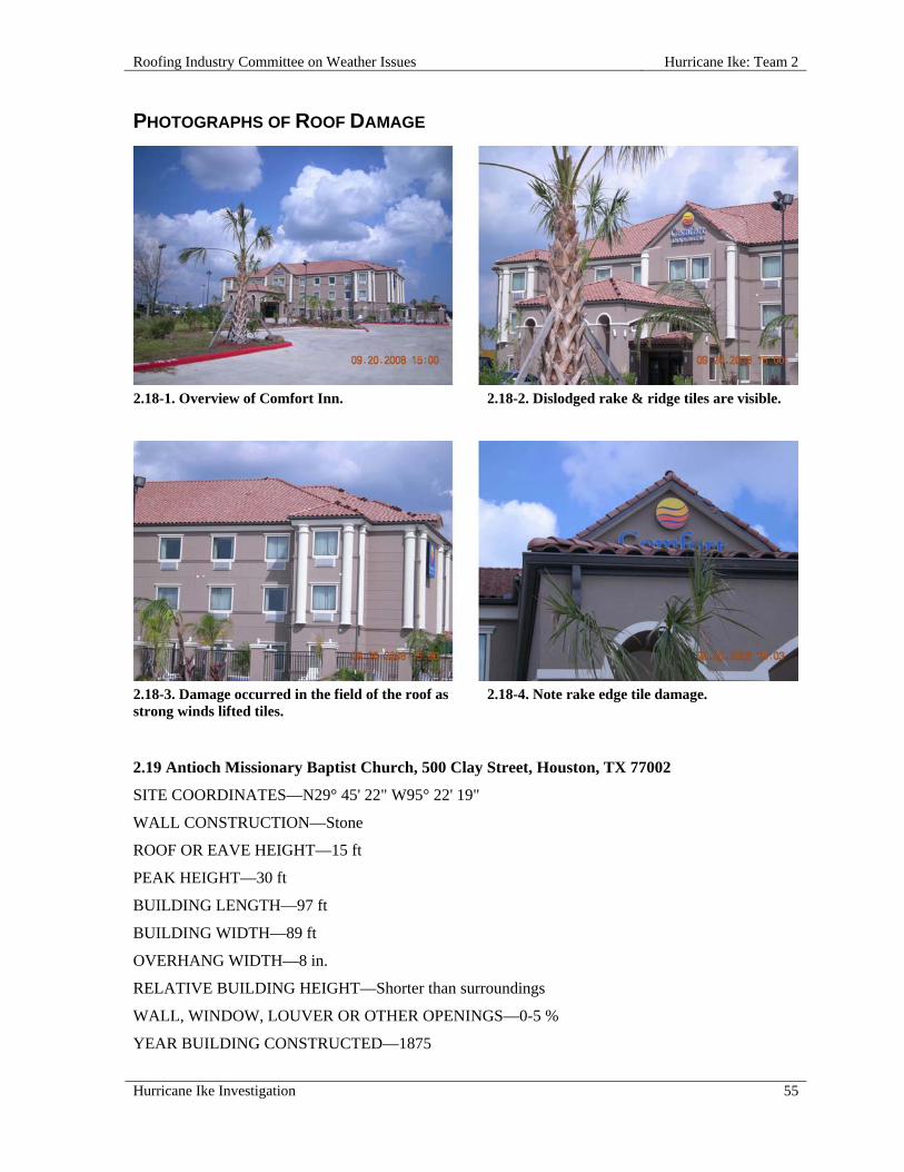
Roofing Industry Committee on Weather Issues Hurricane Ike: Team 2
Hurricane Ike Investigation 55
PHOTOGRAPHS OF ROOF DAMAGE
2.18-1. Overview of Comfort Inn.
2.18-2. Dislodged rake & ridge tiles are visible.
2.18-3. Damage occurred in the field of the roof as strong winds lifted tiles.
2.18-4. Note rake edge tile damage.
2.19 Antioch Missionary Baptist Church, 500 Clay Street, Houston, TX 77002
SITE COORDINATES—N29° 45' 22" W95° 22' 19"
WALL CONSTRUCTION—Stone
ROOF OR EAVE HEIGHT—15 ft
PEAK HEIGHT—30 ft
BUILDING LENGTH—97 ft
BUILDING WIDTH—89 ft
OVERHANG WIDTH—8 in.
RELATIVE BUILDING HEIGHT—Shorter than surroundings
WALL, WINDOW, LOUVER OR OTHER OPENINGS—0-5 %
YEAR BUILDING CONSTRUCTED—1875

Hurricane Ike: Team 2 Roofing Industry Committee on Weather Issues
56 Hurricane Ike Investigation
BUILDING USAGE—Church
BUILDING EXPOSURE—B
BUILDING PRESSURIZED—No
ASCE 7 BASIC WIND SPEED—100 mph
ACTUAL WIND SPEED—90 mph
WIND SPEED AT ROOFTOP—76 mph
VELOCITY PRESSURE—15 psf
PRIMARY WIND DIRECTION—Cornering wind
ROOF SLOPE—Steep Roof
ROOF TYPE—Metal Shingle
TYPE—Steel
PERCENT OF DAMAGE—>0<10%
DAMAGE INITIATION—Shingle interlock failed on some shingles allowing displacement.
DESCRIBE DAMAGE—The ridge and some field metal shingles lifted. The trees on the west side were both blown down. Two stained glass windows on the north elevation were missing, and broken windows were noted. Overall there was very minor damage.
ROOF DAMAGE APPEARED TO BE CAUSED BY:
1. Shingle interlock disengagement, allowing differential movement of shingles.
MISCELLANEOUS NOTES:
1. The building was surrounded by very tall high-rise structures, a parking garage and a pedestrian overpass walkway and trees;
2. Trees on the west side were both blown down; overall very minor damage.

Roofing Industry Committee on Weather Issues Hurricane Ike: Team 2
Hurricane Ike Investigation 57
PHOTOGRAPHS OF ROOF DAMAGE
2.19-1. Texas historic plaque indicates that the church was built in 1875.
2.19-2. North and east elevations.
2.19-3. The metal shingle interlock disengaged, causing failure.
2.19-4. A closer look at a rake edge.

Hurricane Ike: Team 2 Roofing Industry Committee on Weather Issues
58 Hurricane Ike Investigation
2.19-5. Failure of ridge and field metal shingles was due to shingle interlock disengagement.
2.19-6. Large and small window breakage was also noted.
2.19-7. Note damaged shingles along this rake edge.
2.19-8. Slight damage can be seen here, again as a result of interlock disengagement.
2.20 Residence, 4811 North Loop Exit, Houston, TX 77026
SITE COORDINATES—N29° 48' 80" W95° 19' 69"
WALL CONSTRUCTION—Brick facing
ROOF OR EAVE HEIGHT—9 ft
PEAK HEIGHT—20 ft
BUILDING LENGTH—80 ft
BUILDING WIDTH—75 ft
OVERHANG LENGTH—60 ft
OVERHANG WIDTH—8 ft
RELATIVE BUILDING HEIGHT—Equal to surroundings
BUILDING USAGE—Residence
BUILDING EXPOSURE—B

Roofing Industry Committee on Weather Issues Hurricane Ike: Team 2
Hurricane Ike Investigation 59
ASCE 7 BASIC WIND SPEED—100 mph
ACTUAL WIND SPEED—90 mph
WIND SPEED AT ROOFTOP—72 mph
VELOCITY PRESSURE—13 psf
PRIMARY WIND DIRECTION—Perpendicular to short side
ROOF SLOPE—Steep Roof
ROOF TYPE—Metal Shingle
TYPE—Aluminum
ATTACHMENT—Nails
NAILS PER SHINGLE—2
DECK—Wood
UNDERLAYMENT—Felt
RE-COVER—Yes
PERCENT OF DAMAGE—>0<10%
DAMAGE INITIATION—Damage began at eaves and extended up-slope.
DESCRIBE DAMAGE—Damage consisted of displacement and detachment of shingles, as well as some damage to underlying roof system and substrate. Two sections of the roof were damaged. Most damage was in the field of the roof, beginning at the eave extending up-slope. Similarly dislodged shingles were noted at the rear of the house.
ROOF DAMAGE APPEARED TO BE CAUSED BY:
1. Shingles were attached with nails and clips;
2. Clips were engaged in the deck, but not in the shingles.
MISCELLANEOUS NOTES:
1. The site exposure is B from northeast and west, but exposure C from the south, southeast and southwest.

Hurricane Ike: Team 2 Roofing Industry Committee on Weather Issues
60 Hurricane Ike Investigation
PHOTOGRAPHS OF ROOF DAMAGE
2.20-1. Aerial view of the residence.
2.20-2. Another view of the same residence.
2.20-3. The south elevation shows the front, center of this roof.
2.20-4. Primary damage was in the middle of the field of the main roof.
2.20-5. Additional damage was noted on a back corner.
2.20-6. A closer view of the back corner damage.
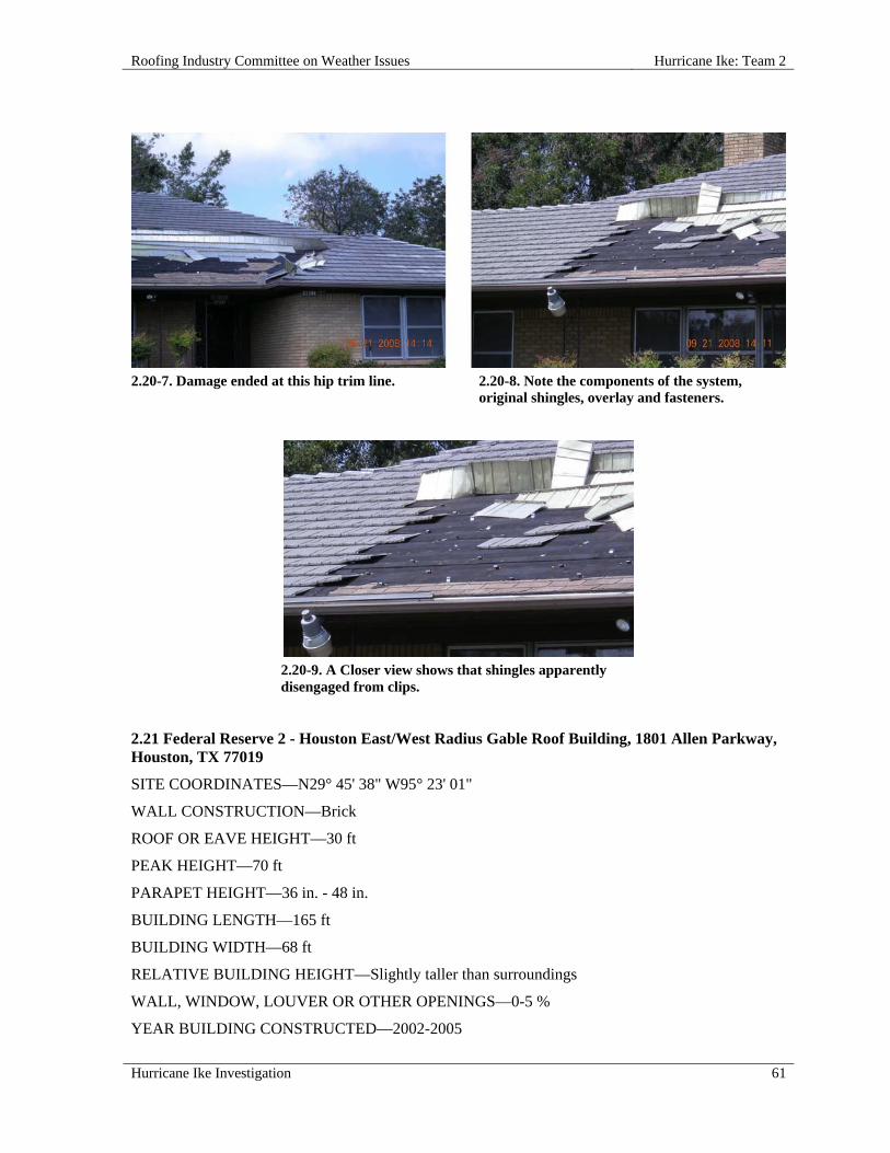
Roofing Industry Committee on Weather Issues Hurricane Ike: Team 2
Hurricane Ike Investigation 61
2.20-7. Damage ended at this hip trim line.
2.20-8. Note the components of the system, original shingles, overlay and fasteners.
2.20-9. A Closer view shows that shingles apparently disengaged from clips.
2.21 Federal Reserve 2 - Houston East/West Radius Gable Roof Building, 1801 Allen Parkway, Houston, TX 77019
SITE COORDINATES—N29° 45' 38" W95° 23' 01"
WALL CONSTRUCTION—Brick
ROOF OR EAVE HEIGHT—30 ft
PEAK HEIGHT—70 ft
PARAPET HEIGHT—36 in. - 48 in.
BUILDING LENGTH—165 ft
BUILDING WIDTH—68 ft
RELATIVE BUILDING HEIGHT—Slightly taller than surroundings
WALL, WINDOW, LOUVER OR OTHER OPENINGS—0-5 %
YEAR BUILDING CONSTRUCTED—2002-2005

Hurricane Ike: Team 2 Roofing Industry Committee on Weather Issues
62 Hurricane Ike Investigation
BUILDING USAGE—Bank
BUILDING EXPOSURE—C
BUILDING PRESSURIZED—No
ASCE 7 BASIC WIND SPEED—100 mph
ACTUAL WIND SPEED—90 mph
WIND SPEED AT ROOFTOP—99 mph
VELOCITY PRESSURE—25 psf
PRIMARY WIND DIRECTION—Perpendicular to long side
ROOF SLOPE—Steep Roof
ROOF TYPE—Concrete or Clay Tile
ATTACHMENT—Nails
TILE SHAPE—Slate
FASTENERS PER TILE—2
UNDERLAYMENT—Yes – appears to be mod bit sheet in photos
RE-COVER—No
PERCENT OF DAMAGE—>0<10%
DAMAGE INITIATION—Damage began at the north elevations of all four roof sections.
DESCRIBE DAMAGE—Building alignment is east-west with damage on each of four subdivisions of the north elevation. Tile was displaced on the radial slope on all four roof sections, both in the field and at wall junctures.
ROOF DAMAGE APPEARED TO BE CAUSED BY:
1. Turbulent wind and lift caused by parapet/wall design and proximity.
MISCELLANEOUS NOTES:
1. This 280,000 sq ft building was less than four years old;
2. This is the first of two buildings with damage; see report 2.22 for details on second building, which had north-south alignment.

Roofing Industry Committee on Weather Issues Hurricane Ike: Team 2
Hurricane Ike Investigation 63
PHOTOGRAPHS OF ROOF DAMAGE
2.21-1. Aerial view of the complex.
2.21-2. Ground-level view shows the north elevation entry.
2.21-3. On the north elevation, all four sections had tile displacement.
2.21-4. East end sections with displaced tile.
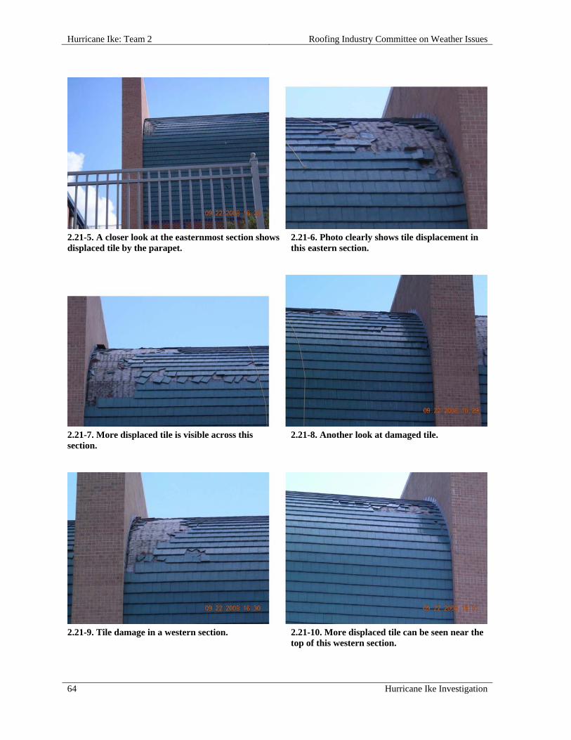
Hurricane Ike: Team 2 Roofing Industry Committee on Weather Issues
64 Hurricane Ike Investigation
2.21-5. A closer look at the easternmost section shows displaced tile by the parapet.
2.21-6. Photo clearly shows tile displacement in this eastern section.
2.21-7. More displaced tile is visible across this section.
2.21-8. Another look at damaged tile.
2.21-9. Tile damage in a western section. 2.21-10. More displaced tile can be seen near the
top of this western section.

Roofing Industry Committee on Weather Issues Hurricane Ike: Team 2
Hurricane Ike Investigation 65
2.22 Federal Reserve 1 - Houston North/South Gable Roof Building, 1801 Allen Parkway, Houston, TX 77019
SITE COORDINATES—N29° 45' 38" W95° 23' 01"
WALL CONSTRUCTION—Brick
ROOF OR EAVE HEIGHT—30 ft
PEAK HEIGHT—70 ft
PARAPET HEIGHT—24 in. - 36 in.
BUILDING LENGTH—295 ft
BUILDING WIDTH—95 ft
RELATIVE BUILDING HEIGHT—Slightly taller than surroundings
WALL, WINDOW, LOUVER OR OTHER OPENINGS—0-5 %
YEAR BUILDING CONSTRUCTED—2002-2005
BUILDING USAGE—Bank
BUILDING EXPOSURE—C
BUILDING PRESSURIZED—No
ASCE 7 BASIC WIND SPEED—100 mph
ACTUAL WIND SPEED—90 mph
WIND SPEED AT ROOFTOP—99 mph
VELOCITY PRESSURE—25 psf
PRIMARY WIND DIRECTION—Perpendicular to long side
ROOF SLOPE—Steep Roof
ROOF TYPE—Concrete or Clay Tile
ATTACHMENT—Nails
TILE SHAPE—Slate
FASTENERS PER TILE—2
UNDERLAYMENT—Yes – appears to be MB sheet in photos
RE-COVER—No
PERCENT OF DAMAGE—>0<10%
DAMAGE INITIATION—North end of building; west elevation by parapet.
DESCRIBE DAMAGE—This rectangular building is aligned north/south with damage on the west elevation. Tile was completely displaced on the east elevation slope.

Hurricane Ike: Team 2 Roofing Industry Committee on Weather Issues
66 Hurricane Ike Investigation
ROOF DAMAGE APPEARED TO BE CAUSED BY:
1. The short parapet (less than 36 in. high) may have created turbulence and lift pressures (negative) that pulled tiles upward.
MISCELLANEOUS NOTES:
1. This is the second of two buildings with damage; see report 2.21 for details on first building, which had east/west alignment;
2. This 280,000 sq ft building was less than four years old.
PHOTOGRAPHS OF ROOF DAMAGE
2.22-1. Aerial view of the complex.
2.22-2. North elevation entry.
2.22-3. On the west elevation at the north end, displaced tile can be seen near the rake edge.
2.22-4. In this closer view, note the proximity of the damaged area to the parapet.
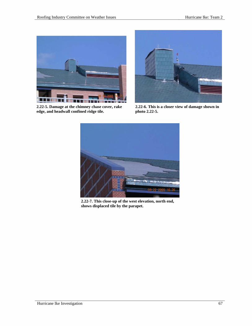
Roofing Industry Committee on Weather Issues Hurricane Ike: Team 2
Hurricane Ike Investigation 67
2.22-5. Damage at the chimney chase cover, rake edge, and headwall confined ridge tile.
2.22-6. This is a closer view of damage shown in photo 2.22-5.
2.22-7. This close-up of the west elevation, north end, shows displaced tile by the parapet.

Roofing Industry Committee on Weather Issues Hurricane Ike: Team 3
Hurricane Ike Investigation 69
HURRICANE IKE: TEAM 3
OVERVIEW
Team 3 focused on metal roof coverings on various buildings around the greater Houston area. The team observed 22 roofs at 20 different sites and documented roof construction, wind-damage conditions, and likely initiation points of wind damage. In most cases, the team was able to climb onto the roofs. In a few cases, information was gathered only from visual observations from the ground or from adjacent roofs. All 22 roofs were on low-rise buildings (less than 60 ft high) in exposure B. Two of the 22 roofs were covered with an insulated steel sheet roof system with flat seams retrofitted over underlying roofs. One, a residential roof, was covered with aluminum shingles. The rest were covered with either architectural or structural standing seam panel systems. Roof decks were generally plywood, with the structural panels installed over metal purlins. Wind-related damage conditions observed on the 22 roofs ranged from minor to extensive. Damage conditions included displacement of edge metal, punctures/tears in roof membranes, withdrawal and/or pull-over of securement fasteners, and at some locations complete roof covering displacement (blow-off).
Team Members
The following members participated on Team 3:
Jim Bush, sample collector Vickie Crenshaw, data recorder (1 day) Phil Mayfield, report writer, photographer Paul Riesebieter, data recorder
Summary Observations
Generally speaking, the most severe damage observed occurred in the following scenarios: 1. Overhanging canopies, which are more vulnerable to wind gusts from below; 2. Panel blow-off due to edge problems; 3. Panel blow-off from internal pressurization due to wind infiltration through door/window
openings, exhaust vents, or other wall openings. Exacerbating the wind infiltration, which triggered panel/edge displacement, were fastening problems such as improper type, inadequate length, inadequate fastening pattern, too few panel clips/cleats, improperly installed clips/cleats, and poor field-seaming of interlocking panels. Predictably, roof systems with good perimeter details had the best success at withstanding hurricane winds. As a general rule, the most pronounced failures begin when metal edge flashings disengage first, allowing wind underneath the panels. Interestingly, First United Methodist Church (Inspection 3.15) appears to be an exception to this rule.

Hurricane Ike: Team 3 Roofing Industry Committee on Weather Issues
70 Hurricane Ike Investigation
INDIVIDUAL ROOF REPORTS
3.01 Louis Gill Service Center (Dickinson), 3120 Deats Road, Dickinson, TX 77539
SITE COORDINATES—N29° 28' 17" W95° 3' 11"
WALL CONSTRUCTION—Steel panel
ROOF OR EAVE HEIGHT—18 ft
PEAK HEIGHT—19.5 ft
BUILDING LENGTH—100 ft
BUILDING WIDTH—60 ft
OVERHANG LENGTH—90 ft
OVERHANG WIDTH—20 ft
RELATIVE BUILDING HEIGHT—Equal to surroundings
WALL, WINDOW, LOUVER OR OTHER OPENINGS—10-20%
BUILDING USAGE—Vehicle maintenance
BUILDING EXPOSURE—B
BUILDING PRESSURIZED—No
ASCE 7 BASIC WIND SPEED—90 mph
ACTUAL WIND SPEED—90 mph
WIND SPEED AT ROOFTOP—72 mph
VELOCITY PRESSURE—13 psf
PRIMARY WIND DIRECTION—All
ROOF SLOPE—Low Slope Roof
TYPE—Steel R-panel, 24 gauge
ATTACHMENT—Screwed to purlins (through-fastened)
SECONDARY SUPPORT TYPE—Steel purlins
SECONDARY SUPPORT SPACING—5 ft o.c.
PUNCTURES #—8-10
TEARS #—3-5
INSULATION TYPE—None
RE-COVER—No
PERCENT OF DAMAGE—>10<25%
DAMAGE INITIATION—Overhead doors blew in on both sides of building, pressurizing building and leading to more damage.

Roofing Industry Committee on Weather Issues Hurricane Ike: Team 3
Hurricane Ike Investigation 71
DESCRIBE DAMAGE—Three large overhead doors were damaged and/or blown off frames. Roof panels were punctured from wind blown doors and/or frames. Overhanging roof sections were damaged and/or detached. Attached (north) section was undamaged.
ROOF DAMAGE APPEARED TO BE CAUSED BY:
1. Winds from the east got under overhanging roof on east side of building, blowing it back onto and across main metal roof, and coming to rest 100 ft southwest of building;
2. Overhead door on east side blew in, pressurizing building, and blowing overhead door at south end up and onto main roof;
3. When wind direction changed from east to north-northwest, overhead door on west side blew in partially;
4. Overhanging roof sections on west side were partially blown down from a combination of winds from north-northwest and impact from east side roof sections as they blew and tumbled from east to west;
5. Punctures on main roof were due to impact from east side roof sections as they blew and tumbled from east to west.
MISCELLANEOUS NOTES:
1. Damaged (southern) portion of building had metal walls and roof functioned as a maintenance garage;
2. Undamaged northern portion of building functioned as the maintenance office and had more structurally sound masonry walls.
PHOTOGRAPHS OF ROOF DAMAGE
3.01-1. View of the southern elevation. The large overhead door (center) was blown up and over the top.
3.01-2. North to south view shows the overhang on the east side, part of which blew up and over the roof.

Hurricane Ike: Team 3 Roofing Industry Committee on Weather Issues
72 Hurricane Ike Investigation
3.01-3. Another view of the east side shows punctures in the main roof from the overhang blow-over.
3.01-4. A northeast to southwest view shows the trail of the east overhang. It is visible in the top of photo, where it came to rest.
3.01-5. Southwest to northeast view of the overhang where it came to rest after blowing onto, then over, the roof.
3.01-6. West side of the building, where overhangs and an overhead door were damaged.

Roofing Industry Committee on Weather Issues Hurricane Ike: Team 3
Hurricane Ike Investigation 73
3.01-7. An overhead door that was blown in on the west side.
3.01-8. South side overhead door was blown out, then onto the roof before becoming detached.
INDIVIDUAL ROOF REPORTS
3.02 Pavilion at Veterans' Memorial Park, Hughes Road, Dickinson, TX 77539
SITE COORDINATES—N29° 27' 7" W95° 2' 32"
WALL CONSTRUCTION—Metal (open)
ROOF OR EAVE HEIGHT—12 ft
PEAK HEIGHT—20 ft
BUILDING LENGTH—100 ft
BUILDING WIDTH—76 ft
OVERHANG LENGTH—80 ft
OVERHANG WIDTH—18 ft
3.01-9. Damage to the roof caused by an overhang that blew onto, then over the roof.
3.01-10. More surface roof damage is visible here, caused by an overhang blowing across the roof.
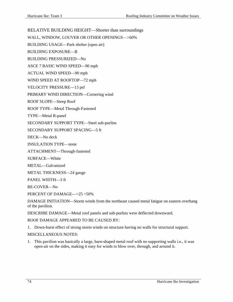
Hurricane Ike: Team 3 Roofing Industry Committee on Weather Issues
74 Hurricane Ike Investigation
RELATIVE BUILDING HEIGHT—Shorter than surroundings
WALL, WINDOW, LOUVER OR OTHER OPENINGS—>60%
BUILDING USAGE—Park shelter (open air)
BUILDING EXPOSURE—B
BUILDING PRESSURIZED—No
ASCE 7 BASIC WIND SPEED—90 mph
ACTUAL WIND SPEED—90 mph
WIND SPEED AT ROOFTOP—72 mph
VELOCITY PRESSURE—13 psf
PRIMARY WIND DIRECTION—Cornering wind
ROOF SLOPE—Steep Roof
ROOF TYPE—Metal Through-Fastened
TYPE—Metal R-panel
SECONDARY SUPPORT TYPE—Steel sub-purlins
SECONDARY SUPPORT SPACING—5 ft
DECK—No deck
INSULATION TYPE—none
ATTACHMENT—Through-fastened
SURFACE—White
METAL—Galvanized
METAL THICKNESS—24 gauge
PANEL WIDTH—3 ft
RE-COVER—No
PERCENT OF DAMAGE—>25 <50%
DAMAGE INITIATION—Storm winds from the northeast caused metal fatigue on eastern overhang of the pavilion.
DESCRIBE DAMAGE—Metal roof panels and sub-purlins were deflected downward.
ROOF DAMAGE APPEARED TO BE CAUSED BY:
1. Down-burst effect of strong storm winds on structure having no walls for structural support.
MISCELLANEOUS NOTES:
1. This pavilion was basically a large, barn-shaped metal roof with no supporting walls i.e., it was open-air on the sides, making it easy for winds to blow over, through, and around it.

Roofing Industry Committee on Weather Issues Hurricane Ike: Team 3
Hurricane Ike Investigation 75
PHOTOGRAPHS OF ROOF DAMAGE
3.02-1. East to west view of the pavilion. The damaging winds came mainly from this side.
3.02-2. View is from northeast to southwest, which is the direction of damaging winds. Note uprooted tree.
3.02-3. East to west view shows an uprooted tree at the right (north) side of the pavilion, indicating wind direction.
3.02-4. Roof damage was limited to this lower section on the east side. Winds approached from the northeast side (far end).
3.02-5. North to south view of the east side shows wind-damaged roofing and purlins.
3.02-6. Looking eastward from inside the pavilion, deflected panels can be seen along the eave.

Hurricane Ike: Team 3 Roofing Industry Committee on Weather Issues
76 Hurricane Ike Investigation
3.02-7. Deformed purlins and panels, resulting from storm winds.
3.03 Dickinson High School, 3800 Baker Street, Dickinson, TX 77539
SITE COORDINATES—N29° 28' 5" W95° 1' 53"
WALL CONSTRUCTION—Metal panel
ROOF OR EAVE HEIGHT—25 ft
PEAK HEIGHT—26 ft
BUILDING LENGTH—90 ft
BUILDING WIDTH—68 ft
RELATIVE BUILDING HEIGHT—Equal to surroundings
WALL, WINDOW, LOUVER OR OTHER OPENINGS—5-10%
BUILDING USAGE—Gymnasium
BUILDING EXPOSURE—B
BUILDING PRESSURIZED—No
ASCE 7 BASIC WIND SPEED—90 mph
ACTUAL WIND SPEED—100 mph
WIND SPEED AT ROOFTOP—83 mph
VELOCITY PRESSURE—18 psf
PRIMARY WIND DIRECTION—Cornering wind
ROOF SLOPE—Low Slope Roof
TYPE—Insulated steel sheet roof system with flat seams
ATTACHMENT—Exposed screws through membrane into steel surface-mounted framework
DECK—Underlying R-panel roof serves as decking for this retrofitted system

Roofing Industry Committee on Weather Issues Hurricane Ike: Team 3
Hurricane Ike Investigation 77
INSULATION TYPE—Expanded polystyrene boards
INSULATION THICKNESS—2 in.
RE-COVER—Yes
PERCENT OF DAMAGE—>10<25%
DAMAGE INITIATION—A cornering wind caused detachment of metal edge, allowing wind to infiltrate and pressurize the roof membrane.
DESCRIBE DAMAGE—Detached metal edge and gutter; roll-back of metal roof membrane, exposing underlying substrate (panel roof).
ROOF DAMAGE APPEARED TO BE CAUSED BY:
1. Poor edge attachment of roof system.
MISCELLANEOUS NOTES:
1. This single ply metal system (steel hat channels, loose laid polystyrene insulation boards and an insulated steel sheet covering) was retrofitted over a more conventional metal roof.
PHOTOGRAPHS OF ROOF DAMAGE
3.03-1. At the southeast corner, winds were too strong for the metal edge securement, allowing the roof to peel back.
3.03-2. This steel sheet roof system was retrofitted over an R-panel roof but was not well anchored at the perimeter.

Hurricane Ike: Team 3 Roofing Industry Committee on Weather Issues
78 Hurricane Ike Investigation
3.03-3. Metal edge became detached and allowed the roof membrane to peel back.
3.03-4. Once the top, left corner attachment failed, it allowed further failure of the membrane and adjoining fascia.
3.04 Dickinson High School Athletic Field House, 3800 Baker Street, Dickinson, TX 77539
SITE COORDINATES—N29° 28' 5" W95° 1' 53"
WALL CONSTRUCTION—Brick
ROOF OR EAVE HEIGHT—15 ft
PEAK HEIGHT—30 ft
BUILDING LENGTH—120 ft
BUILDING WIDTH—36 ft
OVERHANG LENGTH—120 ft
OVERHANG WIDTH—3 ft
RELATIVE BUILDING HEIGHT—Equal to surroundings
WALL, WINDOW, LOUVER OR OTHER OPENINGS—5-10%
BUILDING USAGE—Field house
BUILDING EXPOSURE—B
BUILDING PRESSURIZED—No
ASCE 7 BASIC WIND SPEED—90 mph
ACTUAL WIND SPEED—100 mph
WIND SPEED AT ROOFTOP—85 mph
VELOCITY PRESSURE—18 psf
PRIMARY WIND DIRECTION—All
ROOF SLOPE—Steep Roof
ROOF TYPE—Metal Architectural Standing Seam
TYPE—Insulated steel sheet roof system with flat seams

Roofing Industry Committee on Weather Issues Hurricane Ike: Team 3
Hurricane Ike Investigation 79
ATTACHMENT—Standing Seam Clips
SURFACE—Metal Color blue
METAL—Galvanized
METAL THICKNESS—24 gauge
PANEL WIDTH—16 in.
RE-COVER—No
PERCENT OF DAMAGE—>0<10%
DAMAGE INITIATION—No Damage.
DESCRIBE DAMAGE—This light gauge standing seam roof was on the same campus as a light gauge single ply (steel hat channels, loose laid polystyrene insulation boards and an insulated steel sheet) roof that failed. This conventional roof performed much better than the other (non-conventional) metal roof.
PHOTOGRAPHS OF ROOF DAMAGE
3.04-1. View from south to north. 3.04-2. This standing seam roof performed much better than a single ply metal roof on the same campus.
3.04-3. View of the eave and soffit.

Hurricane Ike: Team 3 Roofing Industry Committee on Weather Issues
80 Hurricane Ike Investigation
3.05 J & S Barber Middle School, 3800 Baker Street, Dickinson, TX 77539
SITE COORDINATES—N29° 28' 7" W95° 1' 51"
ROOF OR EAVE HEIGHT—10 ft
PEAK HEIGHT—13 ft
BUILDING LENGTH—120 ft
BUILDING WIDTH—60 ft
RELATIVE BUILDING HEIGHT—Shorter than surroundings
WALL, WINDOW, LOUVER OR OTHER OPENINGS—5-10%
BUILDING USAGE—Cover / shelter over basketball court
BUILDING EXPOSURE—B
BUILDING PRESSURIZED—Yes
ASCE 7 BASIC WIND SPEED—90 mph
ACTUAL WIND SPEED—90 mph
WIND SPEED AT ROOFTOP—68 mph
VELOCITY PRESSURE—12 psf
PRIMARY WIND DIRECTION—Cornering wind
ROOF SLOPE—Steep Roof
ROOF TYPE—Metal Structural Standing Seam
SECONDARY SUPPORT TYPE—Steel
SECONDARY SUPPORT SPACING—5 ft o.c.
ATTACHMENT—Standing Seam Clips
SURFACE—White
METAL—Painted
METAL THICKNESS—24 gauge
PANEL WIDTH—16 in.
RE-COVER—No
PERCENT OF DAMAGE—>0<10%
DAMAGE INITIATION—Storm winds blowing through this open enclosure caused vertical panel joints to become detached from each other, causing them to swing outward.
DESCRIBE DAMAGE—Vertical metal side panels were blown outward, but remained attached. Gable flashing was damaged due to flashing of vertical metal side panels.
ROOF DAMAGE APPEARED TO BE CAUSED BY:
1. Tongue/groove panel lock design caused failure due to internal umbrella effect;

Roofing Industry Committee on Weather Issues Hurricane Ike: Team 3
Hurricane Ike Investigation 81
2. Vertical panels were installed with screws at the top left and bottom left corners, rather than all four corners. When side lap connections with adjoining panels became detached, panels pivoted from the left side, creating openings between panels.
MISCELLANEOUS NOTES:
1. This pavilion was basically a large metal roof with no supporting walls i.e., it was open-air on the sides, making it easy for winds to blow over, through, and around it.
PHOTOGRAPHS OF ROOF DAMAGE
3.05-1. Structure is an open-air pavilion over a basketball court. Note the missing and dislodged wall roof and wall panels.
3.05-2. Winds blew through and beneath the unprotected roof and wall panels.
3.05-3. The only damage occurred to the wall panels, which were not secured as well as the roof panels.
3.05-4. A closer view of one area of damage shows horizontal purlins (girts) to which the panels were attached.

Hurricane Ike: Team 3 Roofing Industry Committee on Weather Issues
82 Hurricane Ike Investigation
3.05-5. Wall panels were clipped to each other, and then secured along their left sides.
3.05-6. As side connections failed, panels hinged outward and, in some cases, were torn off (at the screw attachments) from high winds.
3.05-7. A close-up view of secondary support members to which wall panels were attached. Screws and bits of panel metal are still visible.
3.06 AAA Storage, 410 Old Galveston Road, Webster, TX 77598
SITE COORDINATES—N29° 32' 15' W95° 6' 56"
WALL CONSTRUCTION—Metal panel (light gauge)
ROOF OR EAVE HEIGHT—12 ft
PEAK HEIGHT—13 ft
BUILDING LENGTH—200 ft
BUILDING WIDTH—72 ft
OVERHANG LENGTH—5 ft
OVERHANG WIDTH—150 ft
RELATIVE BUILDING HEIGHT—Shorter than surroundings
WALL, WINDOW, LOUVER OR OTHER OPENINGS—20-40%

Roofing Industry Committee on Weather Issues Hurricane Ike: Team 3
Hurricane Ike Investigation 83
BUILDING USAGE—Self storage units
BUILDING EXPOSURE—B
BUILDING PRESSURIZED—No
ASCE 7 BASIC WIND SPEED—90 mph
ACTUAL WIND SPEED—90 mph
WIND SPEED AT ROOFTOP—68 mph
VELOCITY PRESSURE—12 psf
PRIMARY WIND DIRECTION—All
ROOF SLOPE—Steep Roof
ROOF TYPE—Metal Architectural Standing Seam
SECONDARY SUPPORT TYPE—"C" stud purlins
SECONDARY SUPPORT SPACING—6 ft o.c.
DECK—None
INSULATION TYPE—None
ATTACHMENT—Standing Seam Clips
SURFACE—White
METAL—Galvanized
METAL THICKNESS—24 gauge
PANEL WIDTH—30 in.
RE-COVER—No
PERCENT OF DAMAGE—>10<25%
DAMAGE INITIATION—Doors blew in, pressurizing building, and then panels blew off.
DESCRIBE DAMAGE—Some roof panels blew off and others were damaged. Some corner trim displacement occurred at the northwest corner.
ROOF DAMAGE APPEARED TO BE CAUSED BY:
1. Fasteners and/or cleats were not adequate to withstand wind pressures, causing edge failure and other damage.
MISCELLANEOUS NOTES:
1. During investigation, a roofing crew was busy installing the exact same system, including fastening methods.

Hurricane Ike: Team 3 Roofing Industry Committee on Weather Issues
84 Hurricane Ike Investigation
PHOTOGRAPHS OF ROOF DAMAGE
3.06-1. These storage units are typical metal structures topped with low slope metal roofs.
3.06-2. One of several overhead doors that blew in from storm winds, pressurizing the building interior.
3.06-3. Displaced roof panels are visible here.
3.06-4. Close-up view of metal panels that tore loose from pressurization of the interior.
3.06-5. Several panels were blown loose in this area.
3.06-6. A closer view shows clips that remained attached to the purlins.
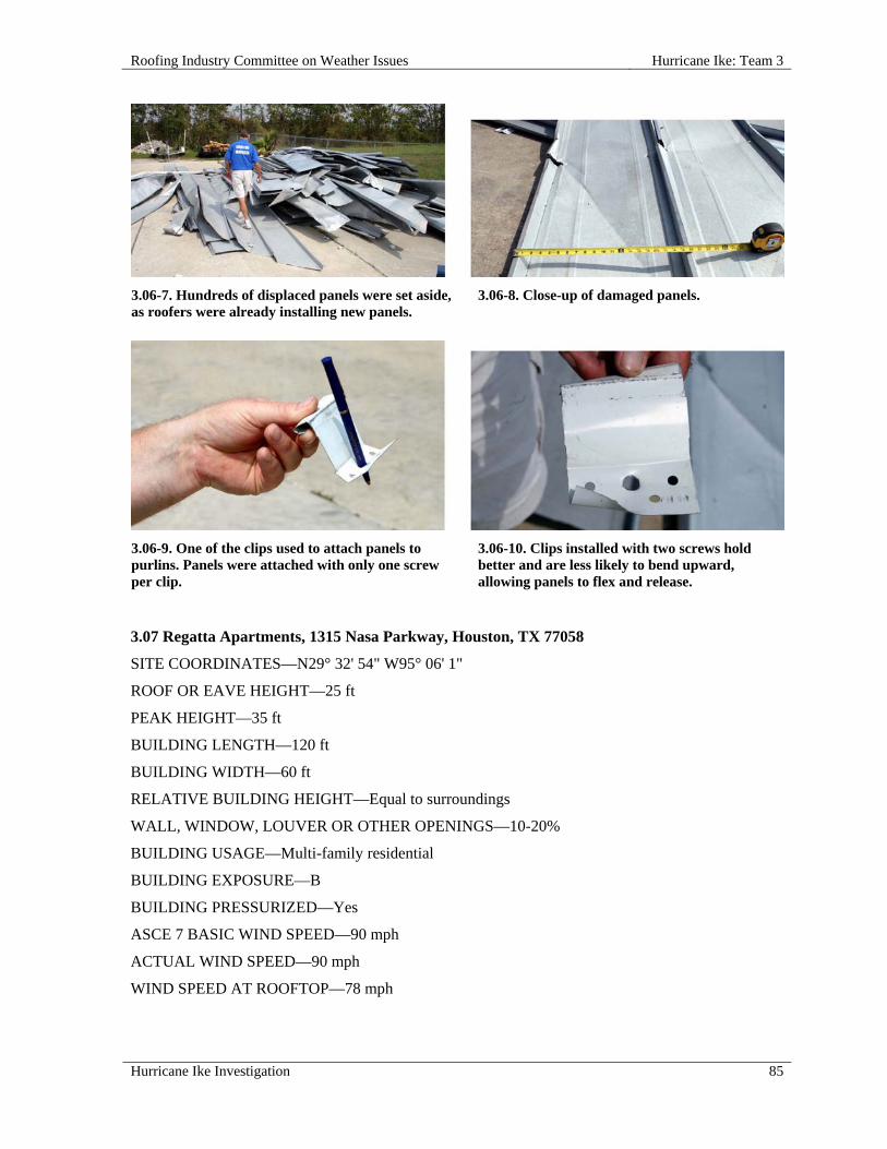
Roofing Industry Committee on Weather Issues Hurricane Ike: Team 3
Hurricane Ike Investigation 85
3.06-7. Hundreds of displaced panels were set aside, as roofers were already installing new panels.
3.06-8. Close-up of damaged panels.
3.06-9. One of the clips used to attach panels to purlins. Panels were attached with only one screw per clip.
3.06-10. Clips installed with two screws hold better and are less likely to bend upward, allowing panels to flex and release.
3.07 Regatta Apartments, 1315 Nasa Parkway, Houston, TX 77058
SITE COORDINATES—N29° 32' 54" W95° 06' 1"
ROOF OR EAVE HEIGHT—25 ft
PEAK HEIGHT—35 ft
BUILDING LENGTH—120 ft
BUILDING WIDTH—60 ft
RELATIVE BUILDING HEIGHT—Equal to surroundings
WALL, WINDOW, LOUVER OR OTHER OPENINGS—10-20%
BUILDING USAGE—Multi-family residential
BUILDING EXPOSURE—B
BUILDING PRESSURIZED—Yes
ASCE 7 BASIC WIND SPEED—90 mph
ACTUAL WIND SPEED—90 mph
WIND SPEED AT ROOFTOP—78 mph

Hurricane Ike: Team 3 Roofing Industry Committee on Weather Issues
86 Hurricane Ike Investigation
VELOCITY PRESSURE—16 psf
PRIMARY WIND DIRECTION—All
ROOF SLOPE—Steep Roof
ROOF TYPE—Metal Architectural Standing Seam
ATTACHMENT—Standing Seam Clips
SURFACE—White
METAL—Galvanized
METAL THICKNESS—24 gauge
PANEL WIDTH—12 in.
RE-COVER—No
PERCENT OF DAMAGE—>10<25%
DAMAGE INITIATION—Wind got under poorly installed components at curved gable.
DESCRIBE DAMAGE—Damage was limited to relatively minor panel disengagement at building ends only.
ROOF DAMAGE APPEARED TO BE CAUSED BY:
1. Poor flashing details at curved gable allowed wind to cause disengagement of some panels.
PHOTOGRAPHS OF ROOF DAMAGE
3.07-1. These roofs are covered mainly in shingles, but with some standing seam at corners.
3.07-2. Close-up shows disengaged batten strips over ribs.

Roofing Industry Committee on Weather Issues Hurricane Ike: Team 3
Hurricane Ike Investigation 87
3.07-3. At lower left, two panels are bowed upward due to inadequate fastening.
3.07-4. Photo shows another displaced batten.
3.08 Mely's Restaurant, 3659 NASA Road 1, Seabrook, TX 77586
SITE COORDINATES—N29° 33' 51" W95° 2' 41"
WALL CONSTRUCTION—Masonry with EIFS covering
ROOF OR EAVE HEIGHT—18 ft
PEAK HEIGHT—28 ft
BUILDING LENGTH—200 ft
BUILDING WIDTH—60 ft
OVERHANG LENGTH—175 ft
OVERHANG WIDTH—8 ft
RELATIVE BUILDING HEIGHT—Equal to surroundings
WALL, WINDOW, LOUVER OR OTHER OPENINGS—10-20%
NUMBER OF PENETRATIONS GREATER THAN 4 ft x 4 ft x 2 ft HIGH—8
BUILDING USAGE—Restaurant at end of strip center
BUILDING EXPOSURE—B
BUILDING PRESSURIZED—Yes
ASCE 7 BASIC WIND SPEED—90 mph
ACTUAL WIND SPEED—90 mph
WIND SPEED AT ROOFTOP—76 mph
VELOCITY PRESSURE—15 psf
PRIMARY WIND DIRECTION—Perpendicular to short side
ROOF SLOPE—Steep Roof
ROOF TYPE—Metal Architectural Standing Seam
DECK—Wood
ATTACHMENT—Standing Seam Clips

Hurricane Ike: Team 3 Roofing Industry Committee on Weather Issues
88 Hurricane Ike Investigation
SURFACE—Metal Color green
METAL—Galvanized
METAL THICKNESS—24 gauge
PANEL WIDTH—12 in.
UNDERLAYMENT—Type II base sheet (asphaltic felt)
RE-COVER—No
PERCENT OF DAMAGE—>10<25%
DAMAGE INITIATION—Edge metal came loose at northern edges, leading to damaged and missing panels.
DESCRIBE DAMAGE—Metal edge, ridge-caps (along hips), and roof panels were damaged and/or detached by winds from the north.
ROOF DAMAGE APPEARED TO BE CAUSED BY:
1. Panels pulled away from clips due to poor clip attachment methods;
2. Too few clips, too few fasteners per clip, and wrong type of fasteners (nails, not screws) resulted in inadequate attachment;
3. Overall assessment: poor workmanship.
PHOTOGRAPHS OF ROOF DAMAGE
3.08-1. Long standing seam panels and edge metal disengaged from roof and rake.
3.08-2. Exposed wood decking and underlayment are visible here, along with damaged panels.

Roofing Industry Committee on Weather Issues Hurricane Ike: Team 3
Hurricane Ike Investigation 89
3.08-3. Some metal panels were blown back onto the roof; others became detached and blew off.
3.08-4. A batten strip partially disengaged from the ribs.
3.08-5. Fastener spacing was inadequate in most areas; clip shown here has only one fastener.
3.08-6. Clips lifted up allowing panels to disengage because two fasteners were not used on each clip.
3.08-7. Note that cleats were used on only one side (right side) of this ridge.
3.08-8. Note the white cleats were installed only on one side of this ridge, and only near the bottom.

Hurricane Ike: Team 3 Roofing Industry Committee on Weather Issues
90 Hurricane Ike Investigation
3.08-9. Not enough clips were used to provide adequate protection from blow-off.
3.08-10. Some panels along eaves disengaged due to poor workmanship in fastening methods.
3.09 Redeeming Faith Church, 511 San Jacinto, LaPorte, TX 77571
SITE COORDINATES—N29° 39' 36" W95° 1' 1"
WALL CONSTRUCTION—Metal panel
ROOF OR EAVE HEIGHT—12 ft
PEAK HEIGHT—18 ft
BUILDING LENGTH—90 ft
BUILDING WIDTH—90 ft
RELATIVE BUILDING HEIGHT—Equal to surroundings
WALL, WINDOW, LOUVER OR OTHER OPENINGS—5-10%
BUILDING USAGE—Church
BUILDING EXPOSURE—B
BUILDING PRESSURIZED—Yes
ASCE 7 BASIC WIND SPEED—90 mph
ACTUAL WIND SPEED—100 mph
WIND SPEED AT ROOFTOP—79 mph
VELOCITY PRESSURE—16 psf
PRIMARY WIND DIRECTION—Cornering wind
ROOF SLOPE—Steep Roof
ROOF TYPE—Metal Through Fastened
INSULATION TYPE—Extruded polystyrene board (used to fill voids between original R-panel roof and top membrane).
INSULATION THICKNESS—2 in.

Roofing Industry Committee on Weather Issues Hurricane Ike: Team 3
Hurricane Ike Investigation 91
ATTACHMENT—This proprietary single ply metal membrane was installed over an existing roof, and fastened into hat channels.
SURFACE—White
METAL—Galvanized
METAL THICKNESS—30 gauge
PANEL WIDTH—30 in.
RE-COVER—Yes
PERCENT OF DAMAGE—>10<25%
DAMAGE INITIATION—Failure of metal edge attachment along western edge led to panels blowing back.
DESCRIBE DAMAGE—Retrofitted metal single ply membrane was blown back several feet onto the field. Metal rake edge and gutter sections were also damaged and/or detached.
ROOF DAMAGE APPEARED TO BE CAUSED BY:
1. Inadequate attachment of perimeter components of retrofitted system.
MISCELLANEOUS NOTES:
1. This single ply metal membrane system (steel hat channels, loose laid polystyrene insulation boards and an insulated steel sheet) was installed over an existing roof and fastened into hat channels.
PHOTOGRAPHS OF ROOF DAMAGE
3.09-1. Northwest to southeast view shows panels that have been blown back onto the field.
3.09-2. A closer view of this single ply metal roof retrofitted over the original metal panel roof.

Hurricane Ike: Team 3 Roofing Industry Committee on Weather Issues
92 Hurricane Ike Investigation
3.09-3. Poor edge and hat channel attachment led to disengagement of this retrofitted metal single ply system.
3.09-4. This is the point along the gutter where damage stopped.
3.10 Sepra Met, 14820 Talcott Street, Houston, TX 77015
SITE COORDINATES—N29° 45' 54" W95° 9' 13"
ROOF OR EAVE HEIGHT—30 ft
PEAK HEIGHT—35 ft
BUILDING LENGTH—150 ft
BUILDING WIDTH—65 ft
RELATIVE BUILDING HEIGHT—Equal to surroundings
WALL, WINDOW, LOUVER OR OTHER OPENINGS—0-5 %
YEAR BUILDING CONSTRUCTED—1972
BUILDING USAGE—Chemical processing
BUILDING EXPOSURE—B
BUILDING PRESSURIZED—No
ASCE 7 BASIC WIND SPEED—90 mph
ACTUAL WIND SPEED—90 mph
WIND SPEED AT ROOFTOP—78 mph
VELOCITY PRESSURE—16 psf
PRIMARY WIND DIRECTION—Cornering wind
ROOF SLOPE—Low Slope Roof
ROOF TYPE—Granular Surfaced BUR
DECK—LWIC
MEMBRANE ATTACHED TO—Lightweight Insulating Concrete
ATTACHED WITH—Fully Adhered - mopped
PERCENT OF DAMAGE—>50<75%

Roofing Industry Committee on Weather Issues Hurricane Ike: Team 3
Hurricane Ike Investigation 93
DAMAGE INITIATION—Beginning near the northwest edge, base sheet-to-LWIC bond failure led to metal edge disengagement and peel-back of the roof membrane.
DESCRIBE DAMAGE—The building was constructed in 1972 but the re-roof was completed four years ago. Damage included edge failure and peel-back of roof assembly from LWIC deck. Tree damage (blown down) was also noted.
ROOF DAMAGE APPEARED TO BE CAUSED BY:
1. Poor Workmanship - Inconsistent fastening of edge metal and nailers; no continuous metal edge cleats were noted;
2. Inadequate and Inconsistent Base Sheet Fastening - LWIC base sheet fastener density was not increased at perimeter and corner areas; base sheet fastener rows were inconsistent; e.g., three fastener rows in some areas, but two rows in others; base sheet fastener spacing (density) observed was not typical for spacing used with LWIC; observed fastener density was 1.93 sq ft per fastener VS industry typical of 0.56 sq ft per fastener;
3. Substrate Problems - Deteriorated and dis-bonded LWIC in perimeter areas exacerbated fastening problems noted above.
MISCELLANEOUS NOTES:
1. Initial storm winds were from west to east, but some damage indicated winds from north to south.
PHOTOGRAPHS OF ROOF DAMAGE
3.10-1. Note the rotted edge nailer, foamed-in edge, spacers used instead of blocking, and a nailer secured only to top surface of vertical side wall. Metal edge has 6 in. girth with neither a hemmed edge nor continuous cleat.
3.10-2. Northeast to southeast view shows membrane peel-back directly in line with the tree that fell to the south along the building's front left side (see photo 3.10-8).

Hurricane Ike: Team 3 Roofing Industry Committee on Weather Issues
94 Hurricane Ike Investigation
3.10-3. Northwest to southwest view shows membrane from west to east.
3.10-4. Unprimed metal edge is secured with non-staggered 1 in., galvanized, non-ring- shanked shingle nails 8 in. o.c.
3.10-5. A close-up of deteriorated metal pan-deck and crumbled LWIC.
3.10-6. The base sheet was secured with either two or three fastener rows. Fastener spacing varied from 2 ft to 3 ft o.c. at side laps, and 2 ft o.c. in center rows.
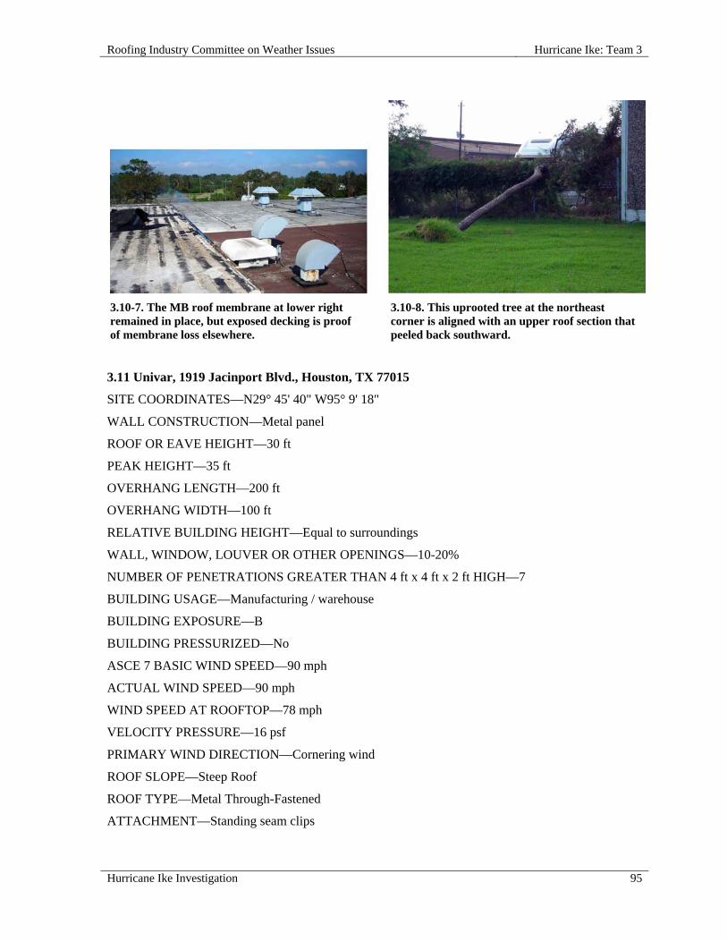
Roofing Industry Committee on Weather Issues Hurricane Ike: Team 3
Hurricane Ike Investigation 95
3.10-7. The MB roof membrane at lower right remained in place, but exposed decking is proof of membrane loss elsewhere.
3.10-8. This uprooted tree at the northeast corner is aligned with an upper roof section that peeled back southward.
3.11 Univar, 1919 Jacinport Blvd., Houston, TX 77015
SITE COORDINATES—N29° 45' 40" W95° 9' 18"
WALL CONSTRUCTION—Metal panel
ROOF OR EAVE HEIGHT—30 ft
PEAK HEIGHT—35 ft
OVERHANG LENGTH—200 ft
OVERHANG WIDTH—100 ft
RELATIVE BUILDING HEIGHT—Equal to surroundings
WALL, WINDOW, LOUVER OR OTHER OPENINGS—10-20%
NUMBER OF PENETRATIONS GREATER THAN 4 ft x 4 ft x 2 ft HIGH—7
BUILDING USAGE—Manufacturing / warehouse
BUILDING EXPOSURE—B
BUILDING PRESSURIZED—No
ASCE 7 BASIC WIND SPEED—90 mph
ACTUAL WIND SPEED—90 mph
WIND SPEED AT ROOFTOP—78 mph
VELOCITY PRESSURE—16 psf
PRIMARY WIND DIRECTION—Cornering wind
ROOF SLOPE—Steep Roof
ROOF TYPE—Metal Through-Fastened
ATTACHMENT—Standing seam clips

Hurricane Ike: Team 3 Roofing Industry Committee on Weather Issues
96 Hurricane Ike Investigation
SURFACE—Metal Color blue
METAL—Galvanized
METAL THICKNESS—24 gauge
RE-COVER—No
PERCENT OF DAMAGE—>10<25%
DAMAGE INITIATION—Damage began at northwest corner.
DESCRIBE DAMAGE—Damage occurred to metal edge and corner trim displacement.
ROOF DAMAGE APPEARED TO BE CAUSED BY:
1. Disengagement of cleat from fascia and trim;
2. Failure most likely caused by large expanse of flashing design (large face areas) within adequate fastening into thin gauge sheet metal.
PHOTOGRAPHS OF ROOF DAMAGE
3.11-1. Flashing was displaced on both sides of this corner.
3.11-2. Failure of eave and gable flashing can be seen in this photo.
3.12 Patent Construction Systems, 2335 Wadsworth, Houston, TX 77015
SITE COORDINATES—N29° 45' 55" W95° 9' 5"
WALL CONSTRUCTION—Metal building
ROOF OR EAVE HEIGHT—30 ft
PEAK HEIGHT—35 ft
BUILDING LENGTH—100 ft
BUILDING WIDTH—40 ft
OVERHANG LENGTH—100 ft
OVERHANG WIDTH—5 ft
RELATIVE BUILDING HEIGHT—Equal to surroundings

Roofing Industry Committee on Weather Issues Hurricane Ike: Team 3
Hurricane Ike Investigation 97
WALL, WINDOW, LOUVER OR OTHER OPENINGS—10-20%
NUMBER OF PENETRATIONS GREATER THAN 4 ft x 4 ft x 2 ft HIGH—4
BUILDING USAGE—Manufacturing / warehouse
BUILDING EXPOSURE—B
BUILDING PRESSURIZED—No
ASCE 7 BASIC WIND SPEED—90 mph
ACTUAL WIND SPEED—90 mph
WIND SPEED AT ROOFTOP—78 mph
VELOCITY PRESSURE—16 psf
PRIMARY WIND DIRECTION—Cornering wind
ROOF SLOPE—Steep Roof
ROOF TYPE—Metal Structural Standing Seam
ATTACHMENT—Through-fastened
SURFACE—White
METAL—Galvanized
METAL THICKNESS—24 gauge
RE-COVER—No
PERCENT OF DAMAGE—>25 <50%
DAMAGE INITIATION—Damage began at roof corners with large overhangs.
DESCRIBE DAMAGE—Corner components, edge details, fascia and gutters were damaged or detached. Some sub-purlins remained attached to metal panels.
ROOF DAMAGE APPEARED TO BE CAUSED BY:
1. Evidence of purlin system still attached to metal roof panels indicates a failure in the connection of the secondary framing member (roof purlin) to the primary structural component rigid frame; was not adequate to withstand wind loads.
MISCELLANEOUS NOTES:
1. Edge details, fascia and gutters appear to fail due to high winds;
2. This type of damage is common on pre-engineered structures with large overhangs and canopies.

Hurricane Ike: Team 3 Roofing Industry Committee on Weather Issues
98 Hurricane Ike Investigation
PHOTOGRAPHS OF ROOF DAMAGE
3.12-1. Note that some sub-purlins remained attached to panels.
3.13 Hair by Popular Demand, 4300-B Fairmont, Pasadena, TX 77504
SITE COORDINATES—N29° 38' 59" W95° 10' 44"
WALL CONSTRUCTION—Block
ROOF OR EAVE HEIGHT—25 ft
PEAK HEIGHT—35 ft
PARAPET HEIGHT—2 ft 6 in.
BUILDING LENGTH—200 ft
BUILDING WIDTH—50 ft
RELATIVE BUILDING HEIGHT—Equal to surroundings
YEAR BUILDING CONSTRUCTED—2006
BUILDING USAGE—Retail / strip mall
BUILDING EXPOSURE—B
BUILDING PRESSURIZED—Yes
ASCE 7 BASIC WIND SPEED—90 mph
ACTUAL WIND SPEED—90 mph
WIND SPEED AT ROOFTOP—78 mph
VELOCITY PRESSURE—16 psf
PRIMARY WIND DIRECTION—Perpendicular to long side
ROOF SLOPE—Steep Roof
ROOF TYPE—Metal Structural Standing Seam
Roofing Industry Committee on Weather Issues Hurricane Ike: Team 3
Hurricane Ike Investigation 99
ATTACHMENT—Standing seam clips
SURFACE—Metal Color red
METAL—Galvanized
METAL THICKNESS—24 gauge
PANEL WIDTH—18 in.
RE-COVER—No
PERCENT OF DAMAGE—>50<75%
DAMAGE INITIATION—Disengagement of perimeter coping led to peel-back of metal panels.
DESCRIBE DAMAGE—Metal roof panel failure occurred at accent towers and eaves.
ROOF DAMAGE APPEARED TO BE CAUSED BY:
1. Panel was installed with fixed points or hold down fastening within ridge assembly and at eave location only; no other clips were used during installation, which caused failure;
2. Fastener pull-out failure at eave locations was due to incorrect fasteners installed in wood blocking;
3. Failure was caused by workmanship, not panel design; coping was held in place with construction adhesive only, rather than cleats and/or fasteners.
MISCELLANEOUS NOTES:
1. This retail center consisted of pre-engineered metal buildings;
2. Building appeared to be relatively new construction i.e., less than two years old;
3. Roof system was 24 gauge metal standing seam with seams spaced 18 in. o.c., installed on purlins spaced approx. 36 in. o.c.;
4. Winds appear to have come from the northwest;
5. It was evident that some corrective measures were performed at some other time due to different fasteners and fastener patterns along eave at various locations. Panels could not have withstood high winds without panel clip fasteners.
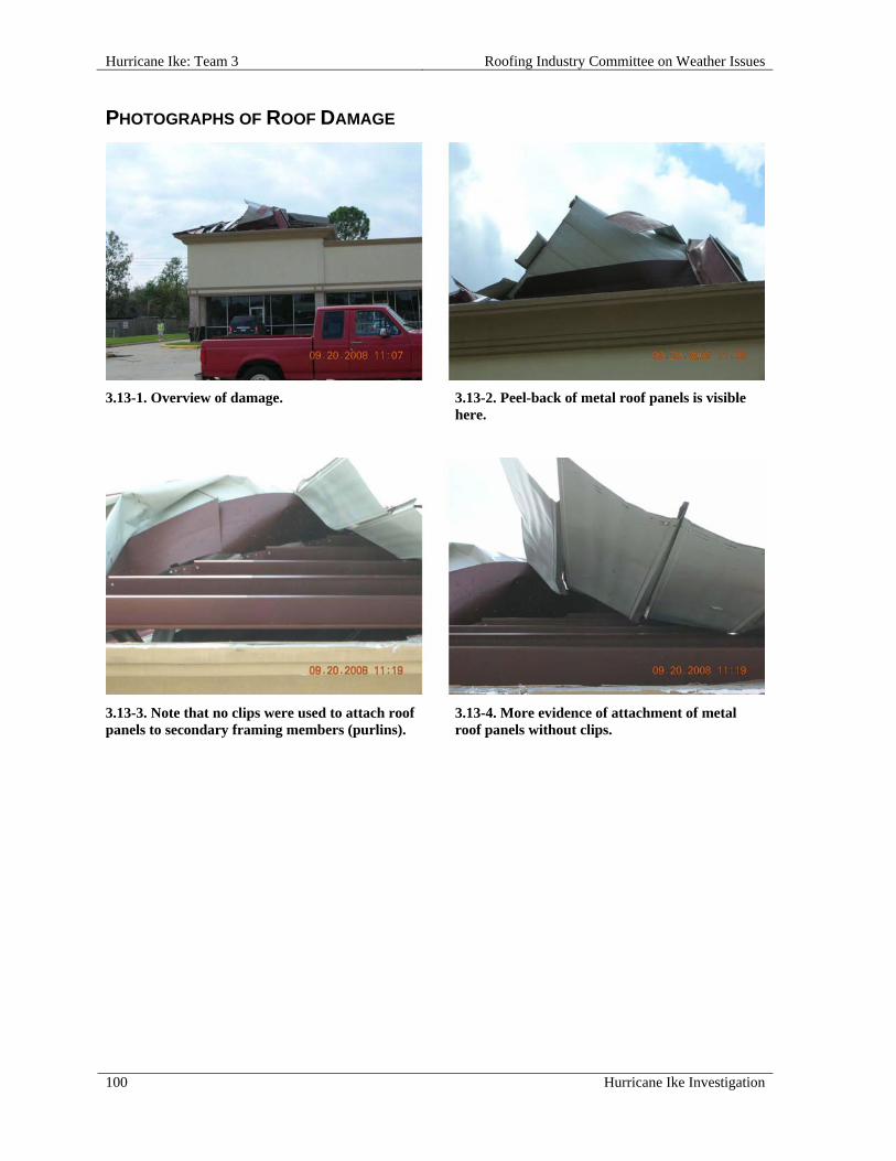
Hurricane Ike: Team 3 Roofing Industry Committee on Weather Issues
100 Hurricane Ike Investigation
PHOTOGRAPHS OF ROOF DAMAGE
3.13-1. Overview of damage. 3.13-2. Peel-back of metal roof panels is visible here.
3.13-3. Note that no clips were used to attach roof panels to secondary framing members (purlins).
3.13-4. More evidence of attachment of metal roof panels without clips.
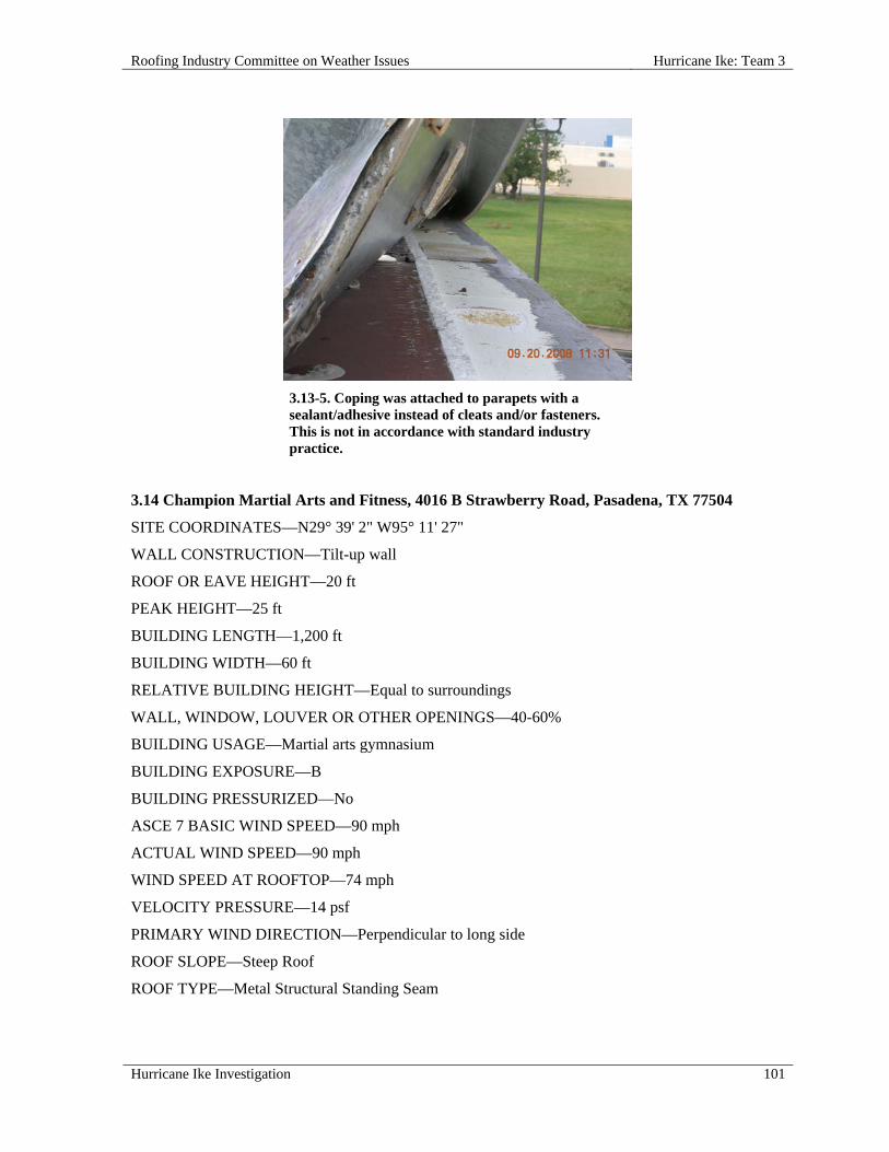
Roofing Industry Committee on Weather Issues Hurricane Ike: Team 3
Hurricane Ike Investigation 101
3.13-5. Coping was attached to parapets with a sealant/adhesive instead of cleats and/or fasteners. This is not in accordance with standard industry practice.
3.14 Champion Martial Arts and Fitness, 4016 B Strawberry Road, Pasadena, TX 77504
SITE COORDINATES—N29° 39' 2" W95° 11' 27"
WALL CONSTRUCTION—Tilt-up wall
ROOF OR EAVE HEIGHT—20 ft
PEAK HEIGHT—25 ft
BUILDING LENGTH—1,200 ft
BUILDING WIDTH—60 ft
RELATIVE BUILDING HEIGHT—Equal to surroundings
WALL, WINDOW, LOUVER OR OTHER OPENINGS—40-60%
BUILDING USAGE—Martial arts gymnasium
BUILDING EXPOSURE—B
BUILDING PRESSURIZED—No
ASCE 7 BASIC WIND SPEED—90 mph
ACTUAL WIND SPEED—90 mph
WIND SPEED AT ROOFTOP—74 mph
VELOCITY PRESSURE—14 psf
PRIMARY WIND DIRECTION—Perpendicular to long side
ROOF SLOPE—Steep Roof
ROOF TYPE—Metal Structural Standing Seam
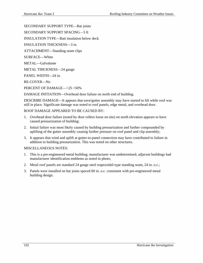
Hurricane Ike: Team 3 Roofing Industry Committee on Weather Issues
102 Hurricane Ike Investigation
SECONDARY SUPPORT TYPE—Bar joists
SECONDARY SUPPORT SPACING—5 ft
INSULATION TYPE—Batt insulation below deck
INSULATION THICKNESS—3 in.
ATTACHMENT—Standing seam clips
SURFACE—White
METAL—Galvalume
METAL THICKNESS—24 gauge
PANEL WIDTH—24 in.
RE-COVER—No
PERCENT OF DAMAGE—>25 <50%
DAMAGE INITIATION—Overhead door failure on north end of building.
DESCRIBE DAMAGE—It appears that eave/gutter assembly may have started to lift while roof was still in place. Significant damage was noted to roof panels, edge metal, and overhead door.
ROOF DAMAGE APPEARED TO BE CAUSED BY:
1. Overhead door failure (noted by door rollers loose on site) on north elevation appears to have caused pressurization of building;
2. Initial failure was most likely caused by building pressurization and further compounded by uplifting of the gutter assembly causing further pressure on roof panel and clip assembly;
3. It appears that wind and uplift at gutter-to-panel connection may have contributed to failure in addition to building pressurization. This was noted on other structures.
MISCELLANEOUS NOTES:
1. This is a pre-engineered metal building; manufacturer was undetermined; adjacent buildings had manufacturer identification emblems as noted in photo;
2. Metal roof panels are standard 24 gauge steel trapezoidal-type standing seam, 24 in. o.c.;
3. Panels were installed on bar joists spaced 60 in. o.c. consistent with pre-engineered metal building design.

Roofing Industry Committee on Weather Issues Hurricane Ike: Team 3
Hurricane Ike Investigation 103
PHOTOGRAPHS OF ROOF DAMAGE
3.14-1. This building was pressurized following overhead door failure.
3.14-2. Panel peel-back at eaves and panel displacement in main field.
3.14-3. Door hardware failure may have led to blow-in of the overhead door and subsequent building pressurization.
3.14-4. Peel back of the eave/gutter connection is shown here.
3.15 First United Methodist Church, 1043 Fairmont Parkway, Pasadena, TX
SITE COORDINATES—N29° 39' 6" W95° 11' 39"
WALL CONSTRUCTION—Metal panel
ROOF OR EAVE HEIGHT—30 ft
PEAK HEIGHT—50 ft
BUILDING LENGTH—100 ft
BUILDING WIDTH—100 ft
RELATIVE BUILDING HEIGHT—Much taller than surroundings
YEAR BUILDING CONSTRUCTED—1986
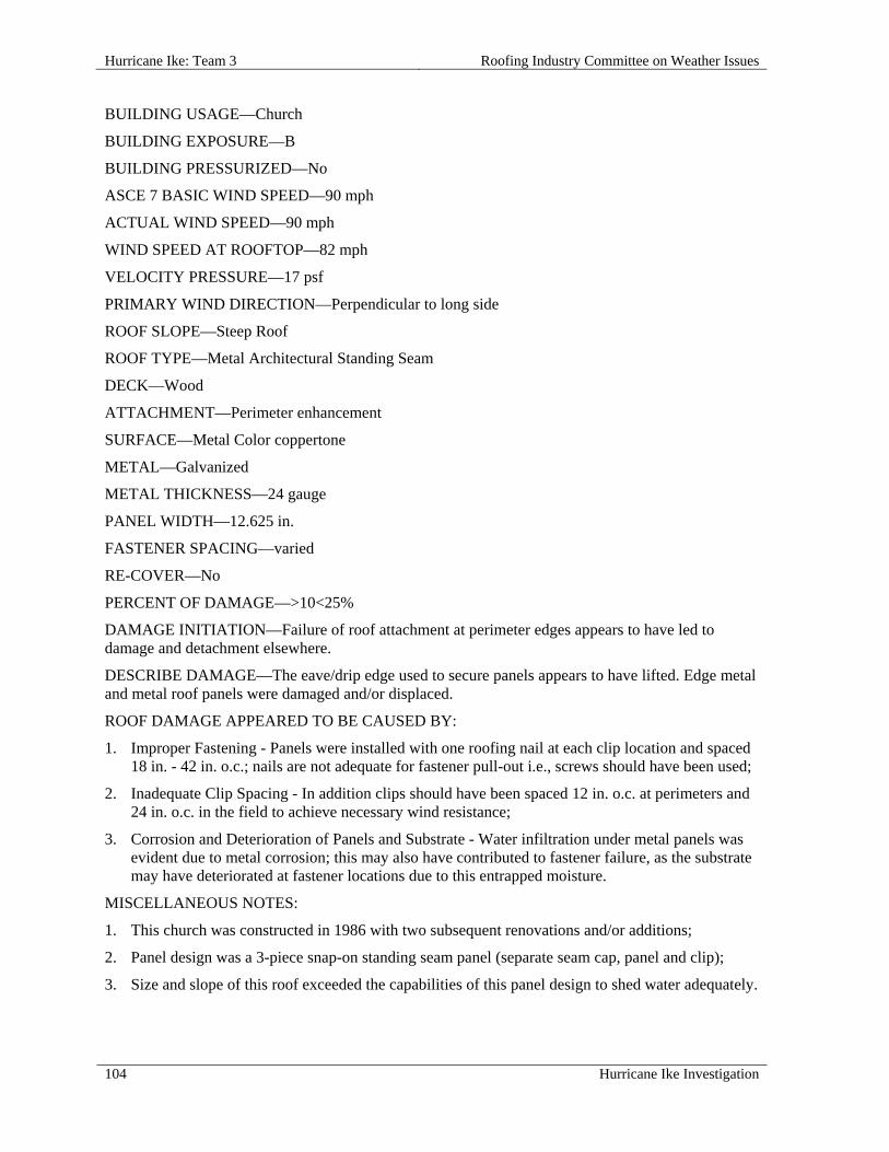
Hurricane Ike: Team 3 Roofing Industry Committee on Weather Issues
104 Hurricane Ike Investigation
BUILDING USAGE—Church
BUILDING EXPOSURE—B
BUILDING PRESSURIZED—No
ASCE 7 BASIC WIND SPEED—90 mph
ACTUAL WIND SPEED—90 mph
WIND SPEED AT ROOFTOP—82 mph
VELOCITY PRESSURE—17 psf
PRIMARY WIND DIRECTION—Perpendicular to long side
ROOF SLOPE—Steep Roof
ROOF TYPE—Metal Architectural Standing Seam
DECK—Wood
ATTACHMENT—Perimeter enhancement
SURFACE—Metal Color coppertone
METAL—Galvanized
METAL THICKNESS—24 gauge
PANEL WIDTH—12.625 in.
FASTENER SPACING—varied
RE-COVER—No
PERCENT OF DAMAGE—>10<25%
DAMAGE INITIATION—Failure of roof attachment at perimeter edges appears to have led to damage and detachment elsewhere.
DESCRIBE DAMAGE—The eave/drip edge used to secure panels appears to have lifted. Edge metal and metal roof panels were damaged and/or displaced.
ROOF DAMAGE APPEARED TO BE CAUSED BY:
1. Improper Fastening - Panels were installed with one roofing nail at each clip location and spaced 18 in. - 42 in. o.c.; nails are not adequate for fastener pull-out i.e., screws should have been used;
2. Inadequate Clip Spacing - In addition clips should have been spaced 12 in. o.c. at perimeters and 24 in. o.c. in the field to achieve necessary wind resistance;
3. Corrosion and Deterioration of Panels and Substrate - Water infiltration under metal panels was evident due to metal corrosion; this may also have contributed to fastener failure, as the substrate may have deteriorated at fastener locations due to this entrapped moisture.
MISCELLANEOUS NOTES:
1. This church was constructed in 1986 with two subsequent renovations and/or additions;
2. Panel design was a 3-piece snap-on standing seam panel (separate seam cap, panel and clip);
3. Size and slope of this roof exceeded the capabilities of this panel design to shed water adequately.
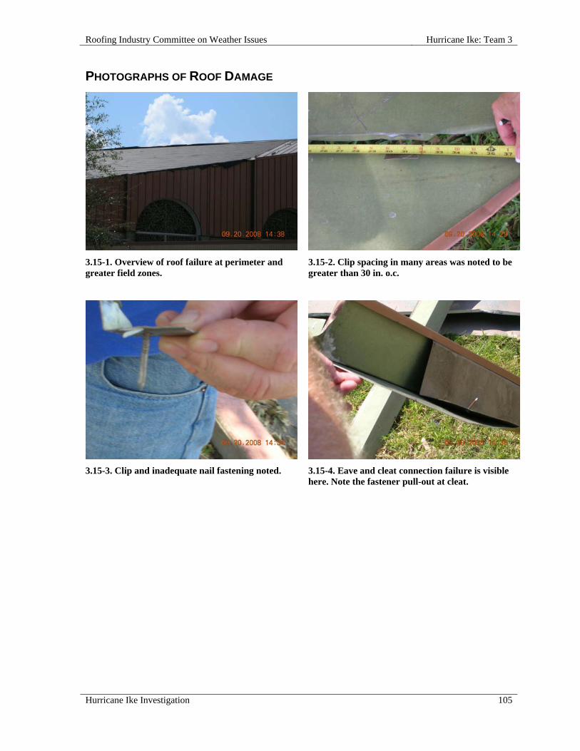
Roofing Industry Committee on Weather Issues Hurricane Ike: Team 3
Hurricane Ike Investigation 105
PHOTOGRAPHS OF ROOF DAMAGE
3.15-1. Overview of roof failure at perimeter andgreater field zones.
3.15-2. Clip spacing in many areas was noted to be greater than 30 in. o.c.
3.15-3. Clip and inadequate nail fastening noted. 3.15-4. Eave and cleat connection failure is visible here. Note the fastener pull-out at cleat.

Hurricane Ike: Team 3 Roofing Industry Committee on Weather Issues
106 Hurricane Ike Investigation
3.15-5. Note evidence of prolonged moisture infiltration within the roof assembly. This was the wrong type and length of panel for this roof pitch.
3.16 Texas Boom Company, 5911 Hamblen Drive, Houston, TX 77396
SITE COORDINATES—N29° 56' 9" W95° 18' 1"
WALL CONSTRUCTION—Masonry
ROOF OR EAVE HEIGHT—20 ft
PEAK HEIGHT—22 ft
BUILDING LENGTH—200 ft
BUILDING WIDTH—140 ft
OVERHANG LENGTH—150 ft
OVERHANG WIDTH—30 ft
RELATIVE BUILDING HEIGHT—Equal to surroundings
WALL, WINDOW, LOUVER OR OTHER OPENINGS—20-40%
BUILDING USAGE—Warehouse
BUILDING EXPOSURE—B
BUILDING PRESSURIZED—Yes
ASCE 7 BASIC WIND SPEED—90 mph
ACTUAL WIND SPEED—90 mph
WIND SPEED AT ROOFTOP—73 mph
VELOCITY PRESSURE—14 psf
PRIMARY WIND DIRECTION—Cornering wind
ROOF SLOPE—Steep Roof
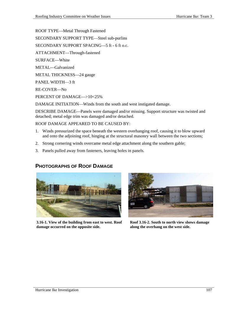
Roofing Industry Committee on Weather Issues Hurricane Ike: Team 3
Hurricane Ike Investigation 107
ROOF TYPE—Metal Through Fastened
SECONDARY SUPPORT TYPE—Steel sub-purlins
SECONDARY SUPPORT SPACING—5 ft - 6 ft o.c.
ATTACHMENT—Through-fastened
SURFACE—White
METAL—Galvanized
METAL THICKNESS—24 gauge
PANEL WIDTH—3 ft
RE-COVER—No
PERCENT OF DAMAGE—>10<25%
DAMAGE INITIATION—Winds from the south and west instigated damage.
DESCRIBE DAMAGE—Panels were damaged and/or missing. Support structure was twisted and detached; metal edge trim was damaged and/or detached.
ROOF DAMAGE APPEARED TO BE CAUSED BY:
1. Winds pressurized the space beneath the western overhanging roof, causing it to blow upward and onto the adjoining roof, hinging at the structural masonry wall between the two sections;
2. Strong cornering winds overcame metal edge attachment along the southern gable;
3. Panels pulled away from fasteners, leaving holes in panels.
PHOTOGRAPHS OF ROOF DAMAGE
3.16-1. View of the building from east to west. Roof damage occurred on the opposite side.
Roof 3.16-2. South to north view shows damage along the overhang on the west side.

Hurricane Ike: Team 3 Roofing Industry Committee on Weather Issues
108 Hurricane Ike Investigation
3.16-3. Metal roof panels are missing along most of the overhang.
3.16-4. Some damage occurred along the metal edge on the south side.
3.16-5. Winds circling around from the northwest side pressurized the area below the overhang, causing panel blow-off.
3.16-6. Twisted purlins are indications of the severity of storm winds.
3.16-7. Roof panels were blown back onto the main roof at right.
3.16-8. The blow-off damage was limited to mainly the overhang, due to better securement at the top of the wall.

Roofing Industry Committee on Weather Issues Hurricane Ike: Team 3
Hurricane Ike Investigation 109
3.17 Brewer Residence, 4811 North Loop East, Houston, TX 77026
SITE COORDINATES—N29° 48' 36" W95° 19' 25"
WALL CONSTRUCTION—Wood studs with masonry facade
ROOF OR EAVE HEIGHT—9 ft
PEAK HEIGHT—17 ft
BUILDING LENGTH—78 ft
BUILDING WIDTH—66 ft
OVERHANG LENGTH—78 ft x 66 ft
OVERHANG WIDTH—3 ft
RELATIVE BUILDING HEIGHT—Equal to surroundings
WALL, WINDOW, LOUVER OR OTHER OPENINGS—5-10%
YEAR BUILDING CONSTRUCTED—1984
BUILDING USAGE—Residence
BUILDING EXPOSURE—B
BUILDING PRESSURIZED—No
ASCE 7 BASIC WIND SPEED—90 mph
ACTUAL WIND SPEED—90 mph
WIND SPEED AT ROOFTOP—70 mph
VELOCITY PRESSURE—13 psf
PRIMARY WIND DIRECTION—All
ROOF SLOPE—Steep Roof
ROOF TYPE—Metal Shingle
TYPE—Aluminum
ATTACHMENT—Clips
SECONDARY SUPPORT TYPE—wood rafters
UNDERLAYMENT—Type II base sheet
RE-COVER—Yes
PERCENT OF DAMAGE—>0<10%
DAMAGE INITIATION—Strong winds instigated damage to metal edge along the south-facing exposures of this retrofitted residential roof.
DESCRIBE DAMAGE—Damage consisted of damage and/or detachment of metal shingles, metal edge, and underlayment ply.
ROOF DAMAGE APPEARED TO BE CAUSED BY:
1. Lifting of metal edge, which allowed air to pressurize spaces between old and new shingles; that pressure caused shingles to release from clips and become dislodged and/or detached.

Hurricane Ike: Team 3 Roofing Industry Committee on Weather Issues
110 Hurricane Ike Investigation
PHOTOGRAPHS OF ROOF DAMAGE
3.17-1. The two damaged areas-far left and far right-are visible in this southwest to northeast photo.
3.17-2. View is southeast to northwest. The east side was undamaged.
3.17-3. The bulk of the damage occurred over the entrance.
3.17-4. Aluminum shingle system installed over asphalt shingles.
3.17-5. Black asphalt roofing felts were installed as an underlayment between the roofs.
3.17-6. Aluminum shingles were anchored with 1 in. spiral-shank aluminum nails.
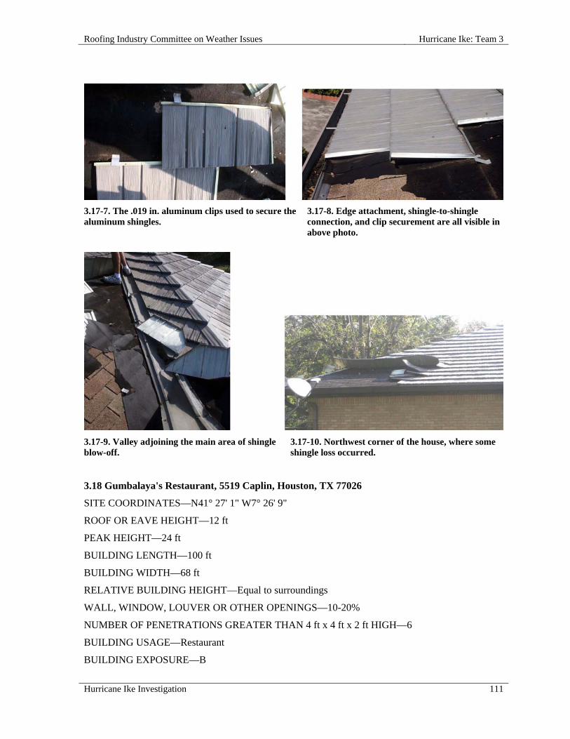
Roofing Industry Committee on Weather Issues Hurricane Ike: Team 3
Hurricane Ike Investigation 111
3.17-9. Valley adjoining the main area of shingle blow-off.
3.17-10. Northwest corner of the house, where some shingle loss occurred.
3.18 Gumbalaya's Restaurant, 5519 Caplin, Houston, TX 77026
SITE COORDINATES—N41° 27' 1" W7° 26' 9"
ROOF OR EAVE HEIGHT—12 ft
PEAK HEIGHT—24 ft
BUILDING LENGTH—100 ft
BUILDING WIDTH—68 ft
RELATIVE BUILDING HEIGHT—Equal to surroundings
WALL, WINDOW, LOUVER OR OTHER OPENINGS—10-20%
NUMBER OF PENETRATIONS GREATER THAN 4 ft x 4 ft x 2 ft HIGH—6
BUILDING USAGE—Restaurant
BUILDING EXPOSURE—B
3.17-7. The .019 in. aluminum clips used to secure the aluminum shingles.
3.17-8. Edge attachment, shingle-to-shingle connection, and clip securement are all visible in above photo.

Hurricane Ike: Team 3 Roofing Industry Committee on Weather Issues
112 Hurricane Ike Investigation
BUILDING PRESSURIZED—No
ASCE 7 BASIC WIND SPEED—90 mph
ACTUAL WIND SPEED—90 mph
WIND SPEED AT ROOFTOP—74 mph
VELOCITY PRESSURE—14 psf
PRIMARY WIND DIRECTION—All
ROOF SLOPE—Steep Roof
ROOF TYPE—Metal Structural Standing Seam
SECONDARY SUPPORT TYPE—Wood joist
DECK—Wood
INSULATION TYPE—Polyisocyanurate foam
INSULATION ATTACHMENT—Screws & plates
ATTACHMENT—Through-fastened
SURFACE—Metal Color
METAL—Galvanized
METAL THICKNESS—26 gauge
PANEL WIDTH—3 ft
UNDERLAYMENT—#30 felt
RE-COVER—No
PERCENT OF DAMAGE—>0<10%
DAMAGE INITIATION—Edge metal disengagement at rakes and eaves.
DESCRIBE DAMAGE—Damaged and/or detached edge metal, roof panels, and underlayment.
ROOF DAMAGE APPEARED TO BE CAUSED BY:
1. Substandard fasteners, both in size and type;
2. Improper fastening i.e., too few and too far apart.
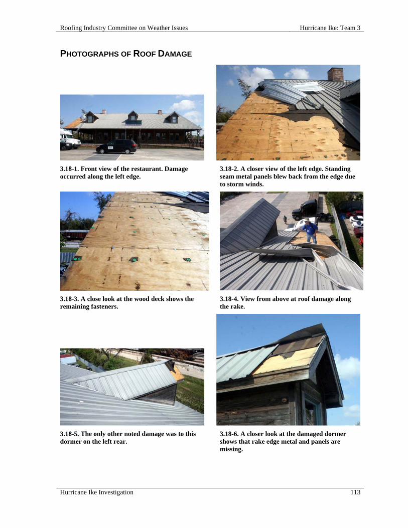
Roofing Industry Committee on Weather Issues Hurricane Ike: Team 3
Hurricane Ike Investigation 113
PHOTOGRAPHS OF ROOF DAMAGE
3.18-1. Front view of the restaurant. Damage occurred along the left edge.
3.18-2. A closer view of the left edge. Standing seam metal panels blew back from the edge due to storm winds.
3.18-3. A close look at the wood deck shows the remaining fasteners.
3.18-4. View from above at roof damage along the rake.
3.18-5. The only other noted damage was to this dormer on the left rear.
3.18-6. A closer look at the damaged dormer shows that rake edge metal and panels are missing.

Hurricane Ike: Team 3 Roofing Industry Committee on Weather Issues
114 Hurricane Ike Investigation
3.18-7. This is one of the undamaged dormers. The rake metal has only two screws securing it.
3.18-8. Damaged rake edge metal on the main roof.
3.18-9. Fastener spacing along the rake edge is inadequate e.g., 28 in. o.c.
3.18-10. Along this exterior rake edge, only one screw is visible in about 9 linear ft of metal.
3.19 Portwall Distribution Center, 200 Portwall, Houston, TX 77029
SITE COORDINATES—N29° 46' 43" W95°16' 28"
WALL CONSTRUCTION—Metal panel
ROOF OR EAVE HEIGHT—36 ft
PEAK HEIGHT—42 ft
BUILDING LENGTH—1,000 ft
BUILDING WIDTH—250 ft
RELATIVE BUILDING HEIGHT—Equal to surroundings
WALL, WINDOW, LOUVER OR OTHER OPENINGS—5-10%
BUILDING USAGE—Warehouse & distribution center
BUILDING EXPOSURE—B
ASCE 7 BASIC WIND SPEED—90 mph
ACTUAL WIND SPEED—90 mph

Roofing Industry Committee on Weather Issues Hurricane Ike: Team 3
Hurricane Ike Investigation 115
WIND SPEED AT ROOFTOP—80 mph
VELOCITY PRESSURE—16 psf
PRIMARY WIND DIRECTION—Cornering wind
ROOF SLOPE—Steep Roof
ROOF TYPE—Metal Structural Standing Seam
ATTACHMENT—Standing seam clips
SURFACE—Metal Color white
METAL—Galvanized
METAL THICKNESS—24 gauge
PANEL WIDTH—unknown
RE-COVER—No
PERCENT OF DAMAGE—>0<10%
DAMAGE INITIATION—Winds infiltrated the edge system along the western end of this large warehouse roof.
DESCRIBE DAMAGE—Damage consisted of deformed and detached edge trim, as well as some roof panels blown up and folded back.
ROOF DAMAGE APPEARED TO BE CAUSED BY:
1. The compression-type attachment of edge trim to cleat was defeated when wind got between trim and wall; sheet metal trim was simply wedged behind the wall cleat; pressurized air got behind the trim, popping it free of the cleat;
2. Cleat fastener placement was inadequate, allowing strong pressure to detach cleats.
PHOTOGRAPHS OF ROOF DAMAGE
3.19-1. Storm winds damaged most of the metal edge of this roof, as well as some roof panels.
3.19-2. This is a closer look at some of the damaged edge system.
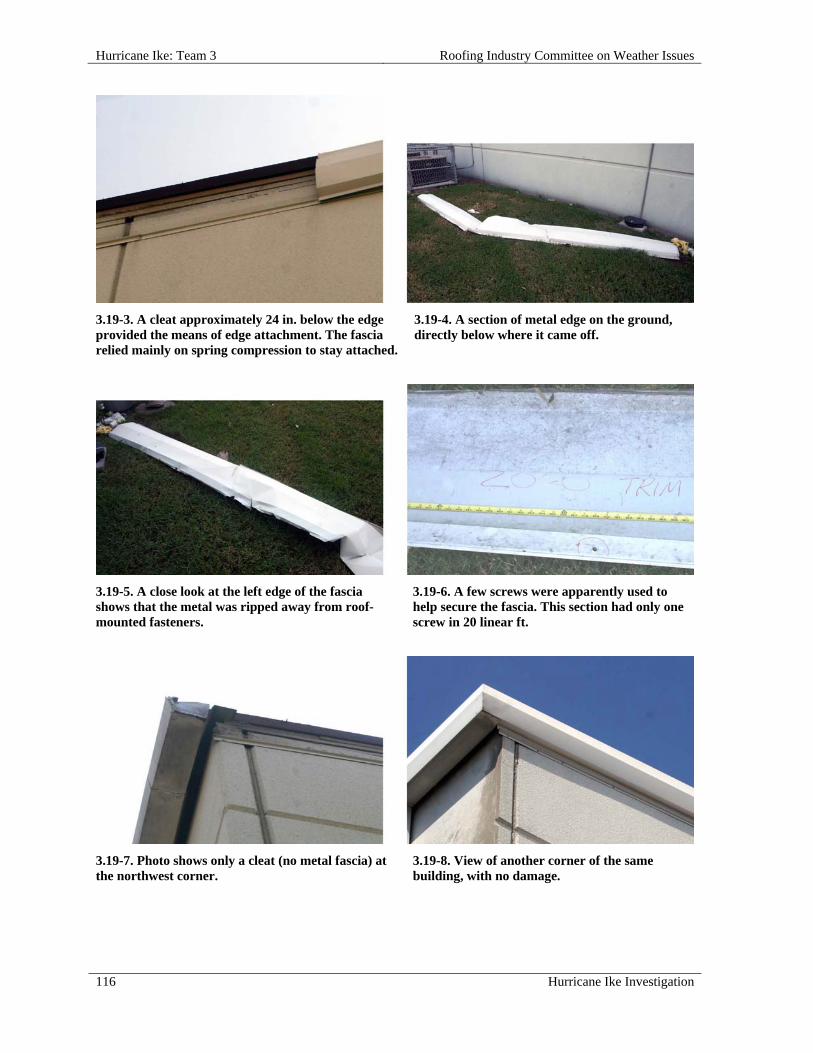
Hurricane Ike: Team 3 Roofing Industry Committee on Weather Issues
116 Hurricane Ike Investigation
3.19-3. A cleat approximately 24 in. below the edge provided the means of edge attachment. The fascia relied mainly on spring compression to stay attached.
3.19-4. A section of metal edge on the ground, directly below where it came off.
3.19-5. A close look at the left edge of the fascia shows that the metal was ripped away from roof-mounted fasteners.
3.19-6. A few screws were apparently used to help secure the fascia. This section had only one screw in 20 linear ft.
3.19-7. Photo shows only a cleat (no metal fascia) at the northwest corner.
3.19-8. View of another corner of the same building, with no damage.

Roofing Industry Committee on Weather Issues Hurricane Ike: Team 3
Hurricane Ike Investigation 117
3.20 St. George Warehouses, 530 Portwall, Houston, TX 77029
SITE COORDINATES—N29° 46' 51" W95° 16' 36"
WALL CONSTRUCTION—Tilt-up wall
ROOF OR EAVE HEIGHT—30 ft
PEAK HEIGHT—33 ft
PARAPET HEIGHT—2 ft
BUILDING LENGTH—280 ft
BUILDING WIDTH—100 ft
OVERHANG LENGTH—5 ft
OVERHANG WIDTH—200 ft
RELATIVE BUILDING HEIGHT—Equal to surroundings
WALL, WINDOW, LOUVER OR OTHER OPENINGS—5-10%
NUMBER OF PENETRATIONS GREATER THAN 4 ft x 4 ft x 2 ft HIGH—3
BUILDING USAGE—Warehouse
BUILDING EXPOSURE—B
BUILDING PRESSURIZED—No
ASCE 7 BASIC WIND SPEED—90 mph
ACTUAL WIND SPEED—90 mph
WIND SPEED AT ROOFTOP—77 mph
VELOCITY PRESSURE—15 psf
PRIMARY WIND DIRECTION—All
ROOF SLOPE—Steep Roof
ROOF TYPE—Metal Through-Fastened
SECONDARY SUPPORT TYPE—Iron framework
SECONDARY SUPPORT SPACING—3 ft x 6 ft
DECK—No deck (only mansard)
INSULATION TYPE—None
ATTACHMENT—Through-fastened
METAL—Painted
METAL THICKNESS—24 gauge
PANEL WIDTH—3 ft
RE-COVER—No
PERCENT OF DAMAGE—>0<10%

Hurricane Ike: Team 3 Roofing Industry Committee on Weather Issues
118 Hurricane Ike Investigation
DAMAGE INITIATION—Wind infiltrated behind mansard, pressurizing that space and blowing panels off from behind.
DESCRIBE DAMAGE—Damage was limited to deflected and/or missing panels.
ROOF DAMAGE APPEARED TO BE CAUSED BY:
1. Wind infiltrated spaces behind mansards, pressurizing the spaces and blowing panels off from behind.
PHOTOGRAPHS OF ROOF DAMAGE
3.20-1. Wind-displaced mansard panels are strewn across the parking lot near the damaged mansards.
3.20-2. Across the parking lot, this is an undamaged mansard similar to those that lost panels.
3.20-3. A closer view of the damaged mansards. 3.21 Exxon Warehouse (East Side), 8501 Portwall, Houston, TX 77029
SITE COORDINATES—N29° 46' 43" W95° 16' 28"
WALL CONSTRUCTION—Metal panel
ROOF OR EAVE HEIGHT—40 ft
PEAK HEIGHT—43 ft
BUILDING LENGTH—500 ft

Roofing Industry Committee on Weather Issues Hurricane Ike: Team 3
Hurricane Ike Investigation 119
BUILDING WIDTH—200 ft
RELATIVE BUILDING HEIGHT—Slightly taller than surroundings
WALL, WINDOW, LOUVER OR OTHER OPENINGS—5-10%
BUILDING USAGE—Storage / distribution
BUILDING EXPOSURE—B
BUILDING PRESSURIZED—No
ASCE 7 BASIC WIND SPEED—90 mph
ACTUAL WIND SPEED—90 mph
WIND SPEED AT ROOFTOP—80 mph
VELOCITY PRESSURE—16 psf
PRIMARY WIND DIRECTION—All
ROOF SLOPE—Steep Roof
ROOF TYPE—Metal Structural Standing Seam
SECONDARY SUPPORT TYPE—Steel sub-purlins
SECONDARY SUPPORT SPACING—4 ft
INSULATION TYPE—Batt insulation below deck
INSULATION THICKNESS—4 in.
ATTACHMENT—Standing seam clips
SURFACE—Metal Color
METAL—Galvanized
METAL THICKNESS—24 gauge
PANEL WIDTH—24 in.
RE-COVER—No
PERCENT OF DAMAGE—>10<25%
DAMAGE INITIATION—An overhead door failure led to blow-off of roof panels and insulation.
DESCRIBE DAMAGE—One large overhead door was blown in; wall panels were blown down; roof panels and metal edge were blown off.
ROOF DAMAGE APPEARED TO BE CAUSED BY:
1. Pressurization of building after overhead door was blown in from north winds.

Hurricane Ike: Team 3 Roofing Industry Committee on Weather Issues
120 Hurricane Ike Investigation
PHOTOGRAPHS OF ROOF DAMAGE
3.21-1. These roofs are formed of three adjoining levels and the inspection focused on areas at the northeast (upper right) corner.
3.21-2. Extensive damage to the low slope metal roofing can be seen at the northwest corner.
3.21-3. East-facing side of the same roof section. Note edge damage.
3.21-4. West-facing side had the largest amount of damaged roofing still in place.
3.21-5. Internal pressure and metal edge failure resulted in much of the upper roof blowing off.
3.21-6. A close-up of the remnants of metal edge after roof panels blew off.
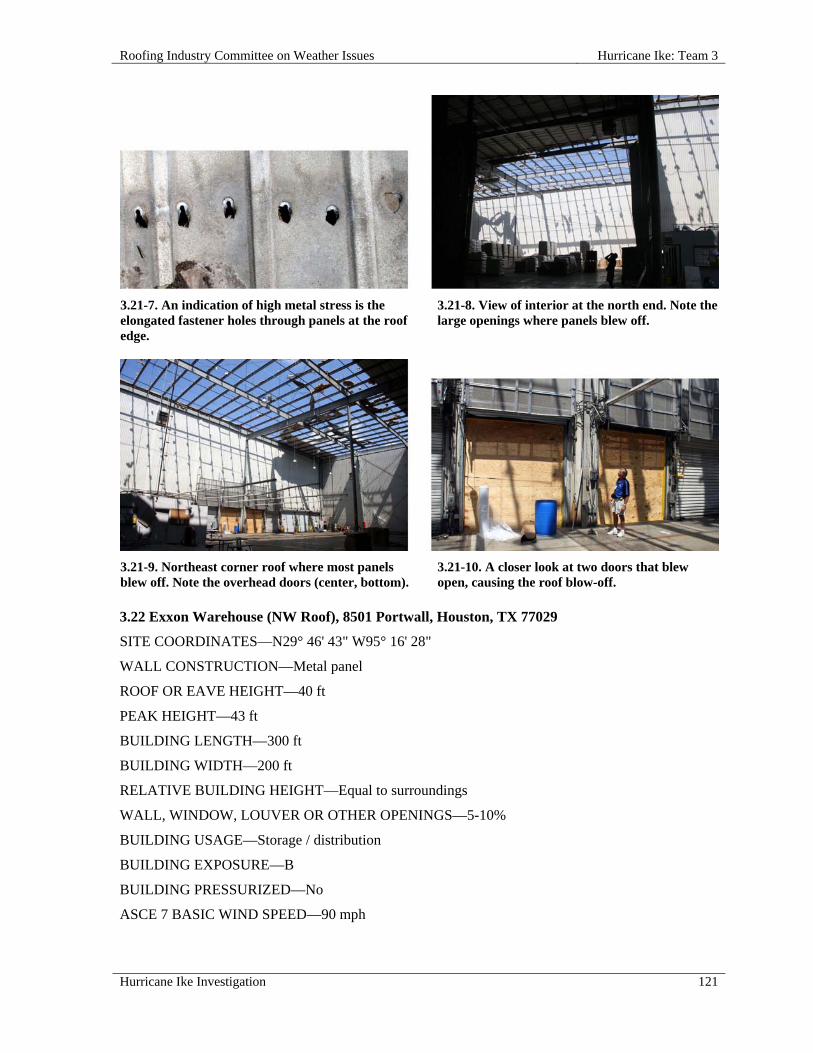
Roofing Industry Committee on Weather Issues Hurricane Ike: Team 3
Hurricane Ike Investigation 121
3.21-7. An indication of high metal stress is the elongated fastener holes through panels at the roof edge.
3.21-8. View of interior at the north end. Note the large openings where panels blew off.
3.21-9. Northeast corner roof where most panels blew off. Note the overhead doors (center, bottom).
3.21-10. A closer look at two doors that blew open, causing the roof blow-off.
3.22 Exxon Warehouse (NW Roof), 8501 Portwall, Houston, TX 77029
SITE COORDINATES—N29° 46' 43" W95° 16' 28"
WALL CONSTRUCTION—Metal panel
ROOF OR EAVE HEIGHT—40 ft
PEAK HEIGHT—43 ft
BUILDING LENGTH—300 ft
BUILDING WIDTH—200 ft
RELATIVE BUILDING HEIGHT—Equal to surroundings
WALL, WINDOW, LOUVER OR OTHER OPENINGS—5-10%
BUILDING USAGE—Storage / distribution
BUILDING EXPOSURE—B
BUILDING PRESSURIZED—No
ASCE 7 BASIC WIND SPEED—90 mph

Hurricane Ike: Team 3 Roofing Industry Committee on Weather Issues
122 Hurricane Ike Investigation
ACTUAL WIND SPEED—90 mph
WIND SPEED AT ROOFTOP—80 mph
VELOCITY PRESSURE—16 psf
PRIMARY WIND DIRECTION—All
ROOF SLOPE—Steep Roof
ROOF TYPE—Metal Through-Fastened
SECONDARY SUPPORT TYPE—Sub-purlins
SECONDARY SUPPORT SPACING—4 ft
INSULATION TYPE—Batt insulation below deck
INSULATION THICKNESS—4 in.
ATTACHMENT—Standing seam clips
SURFACE—Metal Color
METAL—Galvanized
METAL THICKNESS—24 gauge
PANEL WIDTH—24 in.
RE-COVER—No
PERCENT OF DAMAGE—>0<10%
DAMAGE INITIATION—Roof panels and edge flashing blew off at northwest corner.
DESCRIBE DAMAGE—Roof panels and metal edge were damaged and/or detached.
ROOF DAMAGE APPEARED TO BE CAUSED BY:
1. Panels had been previously patched improperly, leaving them susceptible to wind damage;
2. Partial pressurization of interior through openings created by storm winds from the north.
PHOTOGRAPHS OF ROOF DAMAGE
3.22-1. The upper left roof section of this large building is the focus of this investigation.
3.22-2. A long strip of this deck system was blown off, and edge metal was also damaged.
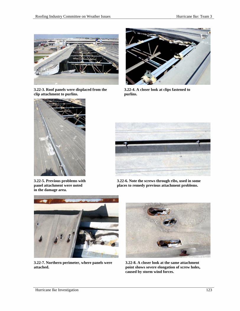
Roofing Industry Committee on Weather Issues Hurricane Ike: Team 3
Hurricane Ike Investigation 123
3.22-3. Roof panels were displaced from the clip attachment to purlins.
3.22-4. A closer look at clips fastened to purlins.
3.22-5. Previous problems with panel attachment were noted in the damage area.
3.22-6. Note the screws through ribs, used in some places to remedy previous attachment problems.
3.22-7. Northern perimeter, where panels were attached.
3.22-8. A closer look at the same attachment point shows severe elongation of screw holes, caused by storm wind forces.

Hurricane Ike: Team 3 Roofing Industry Committee on Weather Issues
124 Hurricane Ike Investigation
3.22-9. This wall opening is one point where storm winds infiltrated the building.
3.22-10. A view from inside, showing holes left where panels were blown off.

Roofing Industry Committee on Weather Issues Hurricane Ike: Team 4
Hurricane Ike Investigation 125
HURRICANE IKE: TEAM 4
Overview Team 4 achieved RICOWI’s objective to obtain factual data through careful site investigation, photographic documentation, gathering building and roof assembly information from the site foremen/technician, and the sharing of mutual knowledge among the team members. The team investigated 13 roofs located in the cities of: Deer Park, Friendswood, Copper Field, Houston, and Pasadena. Although the team typically worked from the highest wind-damaged areas to the lesser wind-damaged areas, there was no attempt to get randomized data.
Team Members
The following members participated on Team 4:
Bas Baskaran, report writer Joe Malpezzi, photographer, report writer Reinhard Schneider, data recorder Joe Strickland, sample collector
Summary Observations
All of the investigated roofs were lows slope systems and less than 60 ft in building height. Two-thirds of them were built-up roofs (BURs) and one-third fell within the single ply roof (SPR) category. Most of the BURs were hot-mopped whereas the SPRs were mechanically attached. These roofing systems were on either commercial, school or public official buildings. The damage ranged from 25 percent to 65 percent of the total roof area. The damages can be grouped in one of the following categories:
Failure propagating from the inadequate edge attachment, i.e. edge failure;
Failure caused by the rooftop units on the waterproofing membrane, i.e. membrane puncture;
Roof envelope failure due to the sudden increase in the building internal pressure, i.e. roof blow-off;
Failure due to inappropriate material combinations mixed with poor installation, i.e. design and workmanship.
Team 4 Suggestions to Improve Wind Uplift Resistance of Roofs
Internal pressure build-up can increase the roof failure probability. Probabilities of window cladding failures are high in hurricane-prone regions, and such failures can significantly increase the internal pressure, which can lead to roof uplift failures. It is recommended that designers should allow provisions to account for such failures during the design and the selection of the roofing system. This can be achieved by classifying the building as partially enclosed per ASCE 7–05 in high wind areas.

Hurricane Ike: Team 4 Roofing Industry Committee on Weather Issues
126 Hurricane Ike Investigation
Perimeters and corners of low slope roofs have been recognized as the most vulnerable areas of the roof. The high uplift found in these areas has been factored into the model national buildings codes, and resisting these loads has been a requirement of the codes for many years. Failure, however, continues to occur at these vulnerable parts of the buildings because both design and installation practices are inadequate. The negative forces at the perimeter must be resisted by adequate mechanical attachment or bonding of the roofing membrane to the substrate and deck. Many designs allow pressurization of the underside of the roofing system, which significantly adds to the loads that must be resisted. The load to be resisted is dynamic, and most tests used to evaluate roofing systems are static, or quasi static. Tests also focus on the vertical force of uplift, but the forces once they break the initial bond or mechanical attachment become peel forces that are not measured in current testing. In current testing, the first mechanical failure (screw withdrawal) or separation of the membrane stops the test. In nature, roofs survived with small amounts of initial failure if the peel forces were resisted. If the peel forces are resisted, catastrophic damage is less likely. Prior to 2004 there were no code requirements for roof edge attachment. As mentioned in other areas of this document, this has been corrected with the addition of Wind Design Guide for Edge Systems Used with Low Slope Roofing Systems, ANSI/SPRI/ES-1 (2003) as a code requirement in the IBC. This illustrates the point, however, that building codes prefer to reference consensus standards as the basis for design and installation requirements. This is where ASTM and other standards developers must work to understand the problems and develop tests and standard practices that provide more pertinent data and functional systems.
Our investigations clearly concluded that the wind uplift resistance of roofs can be significantly improved with minimum increase in the cost by following good application practices. One such example is attachment of the edges with proper fasteners at the required spacing. What is needed is to educate the roofing community through the sharing of factual data collected by the RICOWI teams, which contrasts proper application with poor application methods.

Roofing Industry Committee on Weather Issues Hurricane Ike: Team 4
Hurricane Ike Investigation 127
INDIVIDUAL ROOF REPORTS
4.01 Deer Park High School, 802 Ivy Street, Deer Park, TX 77536
SITE COORDINATES— N29° 42' 17" W95° 7' 15"
WALL CONSTRUCTION—Brick
ROOF OR EAVE HEIGHT—30 ft
PEAK HEIGHT—40 ft
BUILDING LENGTH—138 ft
BUILDING WIDTH—112 ft
OVERHANG LENGTH—Full
OVERHANG WIDTH—2 ft
RELATIVE BUILDING HEIGHT—Equal to surroundings
WALL, WINDOW, LOUVER OR OTHER OPENINGS—0-5 %
NUMBER OF PENETRATIONS GREATER THAN 4 ft x 4 ft x 2 ft HIGH—30
BUILDING USAGE—Gymnasium
BUILDING EXPOSURE—B
BUILDING PRESSURIZED—No
ASCE 7 BASIC WIND SPEED—120 mph
ACTUAL WIND SPEED—90 mph
WIND SPEED AT ROOFTOP—80 mph
VELOCITY PRESSURE—16 psf
PRIMARY WIND DIRECTION—Cornering wind
ROOF SLOPE—Low Slope Roof
ROOF TYPE—Smooth Surfaced BUR
DECK—Cementitious Wood Fiber
INSULATION TYPE—Fiberglass Board
INSULATION THICKNESS— 2 in.
INSULATION ATTACHMENT—Screws & plates
MEMBRANE ATTACHED TO—Insulation
ATTACHED WITH—Fully Adhered - mopped
SURFACE—Aluminum coating
PERCENT OF DAMAGE—>50<75%
DAMAGE INITIATION—Damage began at roof edges and corners.
DESCRIBE DAMAGE—Initial failure is believed to have occurred around the entire perimeter when the metal edge blew off, exposing the deck. Damaged and missing edge components, field membrane, and flashings were conspicuous conditions in most areas.

Hurricane Ike: Team 4 Roofing Industry Committee on Weather Issues
128 Hurricane Ike Investigation
ROOF DAMAGE APPEARED TO BE CAUSED BY:
1. Cleat fastening methods and materials e.g., rusted nails spaced too far apart exacerbated blow-off potential;
2. Poorly fastened base sheet e.g., too few fasteners to provide positive attachment.
PHOTOGRAPHS OF ROOF DAMAGE
4.01-1. Photo shows the dislodged gymnasium roof. 4.01-2. The edge metal attached to the wood nailer.
4.01-3. All edge metal was blown off this roof section. 4.01-4. A close-up view of the damaged BUR with nailer at upper left (two layers of 1 in. thick fiberglass).

Roofing Industry Committee on Weather Issues Hurricane Ike: Team 4
Hurricane Ike Investigation 129
4.01-5. Edge nailer with cleat nails spaced 16 in. o.c. 4.01-6. Edge metal was completely dislodged.
4.01-7. A rusted fastener. 4.01-8. Base sheet fasteners 28 in. o.c. in rows spaced 12 in. apart.
4.02 Deer Park High School, 802 Ivy Street, Deer Park, TX 77536
SITE COORDINATES— N29° 42' 17" W95° 7' 15"
WALL CONSTRUCTION—Brick
ROOF OR EAVE HEIGHT—18 ft
PEAK HEIGHT—18 ft BUILDING LENGTH—220 ft
BUILDING WIDTH—60 ft
RELATIVE BUILDING HEIGHT—Equal to surroundings
WALL, WINDOW, LOUVER OR OTHER OPENINGS—10-20%
NUMBER OF PENETRATIONS GREATER THAN 4 ft x 4 ft x 2 ft HIGH—6
BUILDING USAGE—Classrooms
BUILDING EXPOSURE—B
BUILDING PRESSURIZED—No

Hurricane Ike: Team 4 Roofing Industry Committee on Weather Issues
130 Hurricane Ike Investigation
ASCE 7 BASIC WIND SPEED—120 mph
ACTUAL WIND SPEED—90 mph
WIND SPEED AT ROOFTOP—71 mph
VELOCITY PRESSURE—13 psf
PRIMARY WIND DIRECTION—Cornering wind
ROOF SLOPE—Low Slope Roof
ROOF TYPE—Roll Roofing
DECK—Cementitious Wood Fiber
INSULATION TYPE—Polyisocyanurate foam
INSULATION ATTACHMENT—Screws & plates
MEMBRANE ATTACHED TO—Insulation
ATTACHED WITH—Fully Adhered - mopped
PERCENT OF DAMAGE—>0<10%
DAMAGE INITIATION—No damage.
DESCRIBE DAMAGE—This roof was adjacent to the site of Investigation 4.01. No damage was noted, probably because of tight perimeter fastening of edge metal.
MISCELLANEOUS NOTES:
1. The roofing assembly consisted of a 60 mil PVC fleece-backed membrane hot-mopped to either insulation or to an existing BUR;
2. Edge metal was anchored with a cleat;
3. The horizontal flange of the metal edge was fastened 4 in. o.c.
PHOTOGRAPHS OF ROOF DAMAGE
4.02-1. Hot-mopped fleece-backed PVC membrane. 4.02-2. Six ft wide sheets.

Roofing Industry Committee on Weather Issues Hurricane Ike: Team 4
Hurricane Ike Investigation 131
4.02-3. Overview shows a relatively undisturbed membrane.
4.02-4. Edge metal was fastened 4 in. o.c. Such tight spacing may be why no damage occurred.
4.03 Ace Hardware, 105 W Edgewood Drive, Friendswood, TX 77546
SITE COORDINATES— N29° 31' 55" W95° 12' 24”
WALL CONSTRUCTION—Masonry with stucco
ROOF OR EAVE HEIGHT—18 ft
PEAK HEIGHT—18 ft
PARAPET HEIGHT—0 in. - 24 in.
BUILDING LENGTH—120 ft
BUILDING WIDTH—85 ft
RELATIVE BUILDING HEIGHT—Equal to surroundings
WALL, WINDOW, LOUVER OR OTHER OPENINGS—20-40%
NUMBER OF PENETRATIONS GREATER THAN 4 ft x 4 ft x 2 ft HIGH—8
BUILDING USAGE—Hardware store
BUILDING EXPOSURE—B
BUILDING PRESSURIZED—No
ASCE 7 BASIC WIND SPEED—120 mph
ACTUAL WIND SPEED—90 mph
WIND SPEED AT ROOFTOP—71 mph
VELOCITY PRESSURE—13 psf
PRIMARY WIND DIRECTION—Cornering wind
ROOF SLOPE—Low Slope Roof
ROOF TYPE—Modified Bitumen
DECK—Metal

Hurricane Ike: Team 4 Roofing Industry Committee on Weather Issues
132 Hurricane Ike Investigation
TEARS #—Numerous
MEMBRANE ATTACHED TO—Lightweight Insulating Concrete
ATTACHED WITH—Fully Adhered - mopped
SURFACE—Granules
PERCENT OF DAMAGE—>10<25%
DAMAGE INITIATION—Perimeter coping was the starting point for this failure.
DESCRIBE DAMAGE—Starting with damaged and detached coping, approximately 25% of the roofing system was blown off.
ROOF DAMAGE APPEARED TO BE CAUSED BY:
1. Wood nailers were installed with fasteners spaced 20 in. - 30 in. o.c., which left perimeter coping attachment susceptible to wind damage;
2. Metal coping was installed without a cleat and was attached to the nailer with screws spaced 5 ft o.c. through the top of the coping (at coping section overlaps);
3. Failure occurred when the nailer and coping pulled loose from the structure, creating openings for wind to infiltrate the system.
MISCELLANEOUS NOTES:
1. Base sheet was attached using lightweight concrete fasteners spaced 18 in. o.c. in staggered rows spaced 12 in. apart;
2. O'Reilly's Auto Parts occupied the same building and there is no separate inspection form;
3. A temporary new roof had been installed before the team investigated the damage.
PHOTOGRAPHS OF ROOF DAMAGE
4.03-1. The edge of a temporary roof. 4.03-2. The displaced membrane and temporary roof.
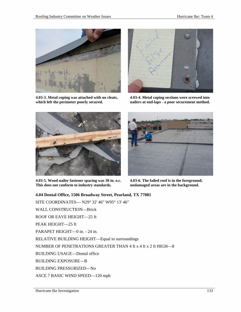
Roofing Industry Committee on Weather Issues Hurricane Ike: Team 4
Hurricane Ike Investigation 133
4.03-3. Metal coping was attached with no cleats, which left the perimeter poorly secured.
4.03-4. Metal coping sections were screwed into nailers at end-laps - a poor securement method.
4.03-5. Wood nailer fastener spacing was 30 in. o.c. This does not conform to industry standards.
4.03-6. The failed roof is in the foreground; undamaged areas are in the background.
4.04 Dental Office, 1506 Broadway Street, Pearland, TX 77081
SITE COORDINATES— N29° 32' 46" W95° 13' 46"
WALL CONSTRUCTION—Brick
ROOF OR EAVE HEIGHT—25 ft
PEAK HEIGHT—25 ft
PARAPET HEIGHT—0 in. - 24 in.
RELATIVE BUILDING HEIGHT—Equal to surroundings
NUMBER OF PENETRATIONS GREATER THAN 4 ft x 4 ft x 2 ft HIGH—8
BUILDING USAGE—Dental office
BUILDING EXPOSURE—B
BUILDING PRESSURIZED—No
ASCE 7 BASIC WIND SPEED—120 mph

Hurricane Ike: Team 4 Roofing Industry Committee on Weather Issues
134 Hurricane Ike Investigation
ACTUAL WIND SPEED—90 mph
WIND SPEED AT ROOFTOP—74 mph
VELOCITY PRESSURE—14 psf
PRIMARY WIND DIRECTION—Cornering wind
ROOF SLOPE—Low Slope Roof
ROOF TYPE—Modified Bitumen
DECK—Wood
INSULATION TYPE—Batt Insulation below deck
MEMBRANE ATTACHED TO—Wood deck
ATTACHED WITH—Fully Adhered - mopped
SURFACE—Granules
PERCENT OF DAMAGE—>10<25%
DAMAGE INITIATION—Damage began at the wall and parapet.
DESCRIBE DAMAGE—This building lost its facade on the windward corner, the same area where approximately 25% of the roofing system was blown off, exposing the deck.
ROOF DAMAGE APPEARED TO BE CAUSED BY:
1. Poor perimeter attachment; metal cap flashing was attached with screws spaced 18 in. o.c. through the inside (roof side) vertical leg only; no cleat was used.
PHOTOGRAPHS OF ROOF DAMAGE
4.04-1. Front facade failure was covered with blue tarps.
4.04-2. Overview of the roof with the failed roof in back - a 2-ply BUR.

Roofing Industry Committee on Weather Issues Hurricane Ike: Team 4
Hurricane Ike Investigation 135
4.04-3. Protective tarps were used to temporarily cover damaged roofing.
4.04-4. No cleat was used for perimeter attachment.
4.04-5. Photo of the metal cap. 4.04-6. Another photo showing no cleats for perimeter attachment.
4.04-7. Edge fastener spacing was 18 in. o.c.

Hurricane Ike: Team 4 Roofing Industry Committee on Weather Issues
136 Hurricane Ike Investigation
4.05 Wal-Mart, 15955 FM 529, Houston, TX 77095
SITE COORDINATES—N29° 52' 45" W95° 39' 7"
WALL CONSTRUCTION—Split face block
ROOF OR EAVE HEIGHT—32 ft
PEAK HEIGHT—32 ft
RELATIVE BUILDING HEIGHT—Equal to surroundings
NUMBER OF PENETRATIONS GREATER THAN 4 ft x 4 ft x 2 ft HIGH—Hundreds
YEAR BUILDING CONSTRUCTED—2000
BUILDING USAGE—Retail
BUILDING EXPOSURE—B
BUILDING PRESSURIZED—No
ASCE 7 BASIC WIND SPEED—100 mph
ACTUAL WIND SPEED—90 mph
WIND SPEED AT ROOFTOP—77 mph
VELOCITY PRESSURE—15 psf
PRIMARY WIND DIRECTION—Perpendicular to long side
ROOF SLOPE—Low Slope Roof
ROOF TYPE—Mechanically Attached Single Ply
DECK—Metal
PUNCTURES #—50+
INSULATION TYPE—Polyisocyanurate Foam
INSULATION ATTACHMENT—Screws & plates
MEMBRANE—TPO
SURFACE—White
PERCENT OF DAMAGE—>0<10%
DAMAGE INITIATION—The northwest corner of the wall was the starting point for damage.
DESCRIBE DAMAGE—Damage consisted of multiple punctures and dislodged metal edge and wall cap (100 ft total). The roof membrane appeared intact other than punctures.
ROOF DAMAGE APPEARED TO BE CAUSED BY:
1. Tumbling, wind-driven debris caused numerous punctures.
MISCELLANEOUS NOTES:
1. This 10 ft wide TPO was mechanically fastened to the steel deck 12 in. o.c.;
2. The continuous cleat was fastened with smooth-shank nails 30 in o.c.;
3. Approximately 100 lineal ft of coping was blown loose causing delamination of the wall flashing in that area;

Roofing Industry Committee on Weather Issues Hurricane Ike: Team 4
Hurricane Ike Investigation 137
4. Rows of fasteners used to secure the membrane prevented the membrane from being blown back and exposing the deck;
5. There was wind damage on adjacent property.
PHOTOGRAPHS OF ROOF DAMAGE
4.05-1. Mechanically attached TPO system over insulation over steel deck.
4.05-2. Wind damage on adjacent property.
4.05-3. The 10 ft wide TPO sheets were fastened 12 in. o.c.
4.05-4. Displaced edge metal.

Hurricane Ike: Team 4 Roofing Industry Committee on Weather Issues
138 Hurricane Ike Investigation
4.05-5. This 10 ft cleat was fastened with nails 27 in. o.c.
4.05-6. A temporary repair to the punctured membrane.
4.06 Delmar Stadium, 1900 Mangum Road, Houston, TX 77092
SITE COORDINATES—N29° 48' 9" W95° 27' 31"
WALL CONSTRUCTION—Concrete panels
ROOF OR EAVE HEIGHT—20 ft
PEAK HEIGHT—35 ft
BUILDING LENGTH—200 ft
BUILDING WIDTH—50 ft
WALL, WINDOW, LOUVER OR OTHER OPENINGS—0-5 %
BUILDING USAGE—Field office
BUILDING EXPOSURE—B
ASCE 7 BASIC WIND SPEED—100 mph
ACTUAL WIND SPEED—90 mph
WIND SPEED AT ROOFTOP—78 mph
VELOCITY PRESSURE—16 psf
ROOF SLOPE—Low Slope Roof
ROOF TYPE—Smooth Surfaced BUR
DECK—Cementitious Wood Fiber
MEMBRANE ATTACHED TO—Wood Fiber
ATTACHED WITH—Fully Adhered - mopped
SURFACE—White coating
PERCENT OF DAMAGE—>0<10%
DAMAGE INITIATION—Damage started at a corner overhang.
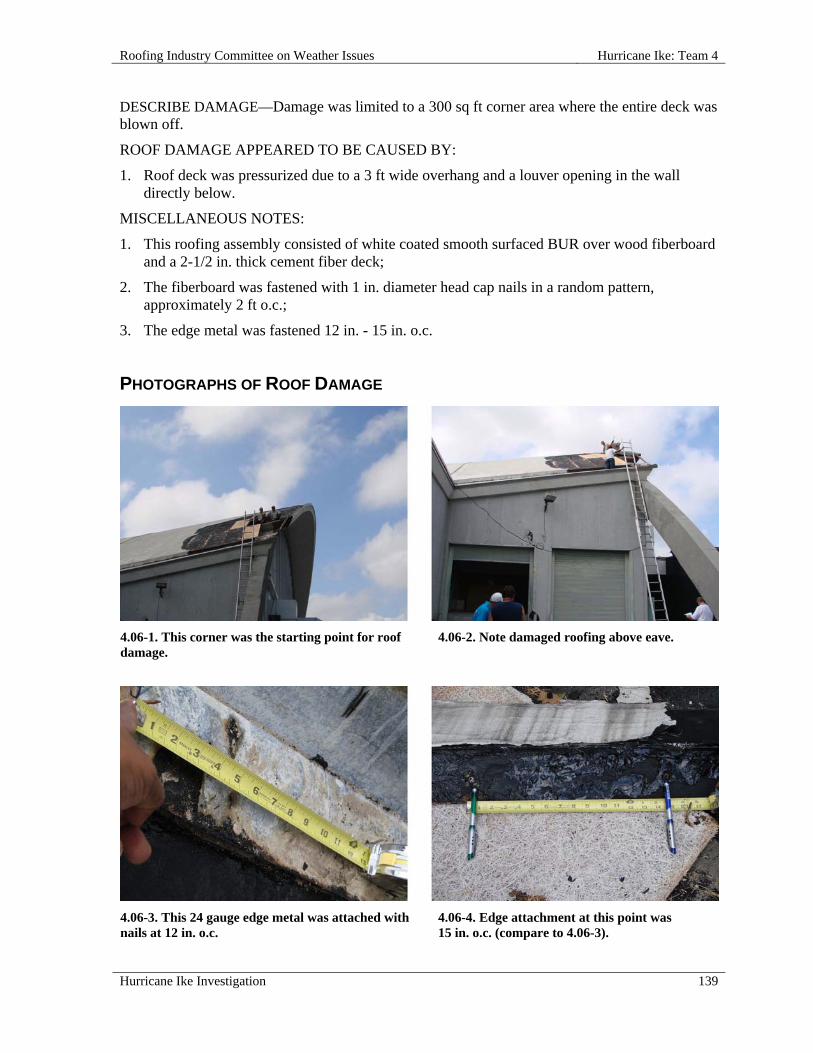
Roofing Industry Committee on Weather Issues Hurricane Ike: Team 4
Hurricane Ike Investigation 139
DESCRIBE DAMAGE—Damage was limited to a 300 sq ft corner area where the entire deck was blown off.
ROOF DAMAGE APPEARED TO BE CAUSED BY:
1. Roof deck was pressurized due to a 3 ft wide overhang and a louver opening in the wall directly below.
MISCELLANEOUS NOTES:
1. This roofing assembly consisted of white coated smooth surfaced BUR over wood fiberboard and a 2-1/2 in. thick cement fiber deck;
2. The fiberboard was fastened with 1 in. diameter head cap nails in a random pattern, approximately 2 ft o.c.;
3. The edge metal was fastened 12 in. - 15 in. o.c.
PHOTOGRAPHS OF ROOF DAMAGE
4.06-1. This corner was the starting point for roof damage.
4.06-2. Note damaged roofing above eave.
4.06-3. This 24 gauge edge metal was attached with nails at 12 in. o.c.
4.06-4. Edge attachment at this point was 15 in. o.c. (compare to 4.06-3).

Hurricane Ike: Team 4 Roofing Industry Committee on Weather Issues
140 Hurricane Ike Investigation
4.06-5. The louver blew out. 4.07 Jem Books, 4815 FM 2351 Road #101, Friendswood, TX 77546
SITE COORDINATES—N29° 32' 52" W95° 11' 23"
WALL CONSTRUCTION—Wood frame
ROOF OR EAVE HEIGHT—22 ft
PEAK HEIGHT—23 ft
PARAPET HEIGHT—10 in. - 24 in.
BUILDING LENGTH—100 ft
BUILDING WIDTH—50 ft
RELATIVE BUILDING HEIGHT—Equal to surroundings
WALL, WINDOW, LOUVER OR OTHER OPENINGS—0-5 %
YEAR BUILDING CONSTRUCTED—1978
BUILDING USAGE—Office & retail
BUILDING EXPOSURE—B
BUILDING PRESSURIZED—No
ASCE 7 BASIC WIND SPEED—120 mph
ACTUAL WIND SPEED—90 mph
WIND SPEED AT ROOFTOP—74 mph
VELOCITY PRESSURE—14 psf
PRIMARY WIND DIRECTION—Cornering wind
ROOF SLOPE—Low Slope Roof
ROOF TYPE—Granular Surfaced BUR
DECK—Wood
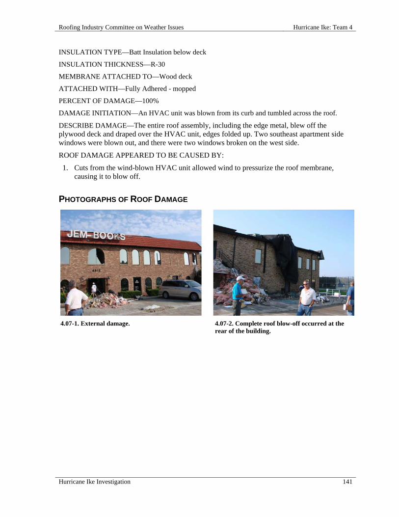
Roofing Industry Committee on Weather Issues Hurricane Ike: Team 4
Hurricane Ike Investigation 141
INSULATION TYPE—Batt Insulation below deck
INSULATION THICKNESS—R-30
MEMBRANE ATTACHED TO—Wood deck
ATTACHED WITH—Fully Adhered - mopped
PERCENT OF DAMAGE—100%
DAMAGE INITIATION—An HVAC unit was blown from its curb and tumbled across the roof.
DESCRIBE DAMAGE—The entire roof assembly, including the edge metal, blew off the plywood deck and draped over the HVAC unit, edges folded up. Two southeast apartment side windows were blown out, and there were two windows broken on the west side.
ROOF DAMAGE APPEARED TO BE CAUSED BY:
1. Cuts from the wind-blown HVAC unit allowed wind to pressurize the roof membrane, causing it to blow off.
PHOTOGRAPHS OF ROOF DAMAGE
4.07-1. External damage. 4.07-2. Complete roof blow-off occurred at the rear of the building.

Hurricane Ike: Team 4 Roofing Industry Committee on Weather Issues
142 Hurricane Ike Investigation
4.07-3. A rooftop view shows conspicuous damage. 4.07-4. A pile of detached roof assembly - 2-ply BUR and mineral surfaced cap.
4.08 Macy's, 800 Northwest Mall, Houston, TX 77092
SITE COORDINATES—N29° 48' 55" W95° 27' 16"
WALL CONSTRUCTION—Masonry
ROOF OR EAVE HEIGHT—35 ft
PEAK HEIGHT—50 ft
PARAPET HEIGHT—0 in. - 12 in.
BUILDING LENGTH—400 ft
BUILDING WIDTH—300 ft
OVERHANG LENGTH—400 ft
OVERHANG WIDTH—300 ft
WALL, WINDOW, LOUVER OR OTHER OPENINGS—0-5 %
NUMBER OF PENETRATIONS GREATER THAN 4 ft x 4 ft x 2 ft HIGH—6
YEAR BUILDING CONSTRUCTED—1968
BUILDING USAGE—Retail
BUILDING EXPOSURE—B
BUILDING PRESSURIZED—No
ASCE 7 BASIC WIND SPEED—110 mph
ACTUAL WIND SPEED—80 mph
WIND SPEED AT ROOFTOP—73 mph
VELOCITY PRESSURE—14 psf
PRIMARY WIND DIRECTION—Cornering wind

Roofing Industry Committee on Weather Issues Hurricane Ike: Team 4
Hurricane Ike Investigation 143
ROOF SLOPE—Low Slope Roof
ROOF TYPE—Gravel Surfaced BUR
DECK—Metal
INSULATION TYPE—Fiberglass Board
INSULATION THICKNESS—2 in.
INSULATION ATTACHMENT—Asphalt
MEMBRANE ATTACHED TO—Lightweight Insulating Concrete
ATTACHED WITH—Split-shank fasteners
PERCENT OF DAMAGE—>0<10%
DAMAGE INITIATION— Edge metal failure had the domino-effect of damage to two roof levels.
DESCRIBE DAMAGE—The inspection report combines the upper and lower roofs of this building (gravel surfaced BUR and aluminum-coated smooth surfaced BUR).
ROOF DAMAGE APPEARED TO BE CAUSED BY:
4.08.1 Upper Level
1. Half of the high roof was blown off when, it appears, the gravel stop pulled loose;
2. Edge metal on the elevated roof reportedly pulled loose allowing the roofing system to blow back; attachment of the edging is unknown.
4.08.2 Lower Level
1. Loose roofing material pulled several rooftop units down onto this lower roof causing punctures and cuts.
MISCELLANEOUS NOTES:
1. Upper Roof (4.08.1) was gravel surfaced BUR over a steel deck;
2. Lower roof (4.08.2) - half of the roof was a gravel surfaced BUR as described in 4.08.1; the other half was an aluminum-coated smooth surfaced BUR; deck was unknown;
3. All debris had been removed and temporary repairs made at the time of the inspection.

Hurricane Ike: Team 4 Roofing Industry Committee on Weather Issues
144 Hurricane Ike Investigation
PHOTOGRAPHS OF ROOF DAMAGE
4.08-1. View from the ground. 4.08-2. A white penthouse is seen here on the main roof.
4.08-3. Repairs on the penthouse roof are visible. 4.08-4. A mechanical unit and screw base.
4.08-5. A large puncture repair on the main roof. 4.08-6. More puncture repairs on the main roof.
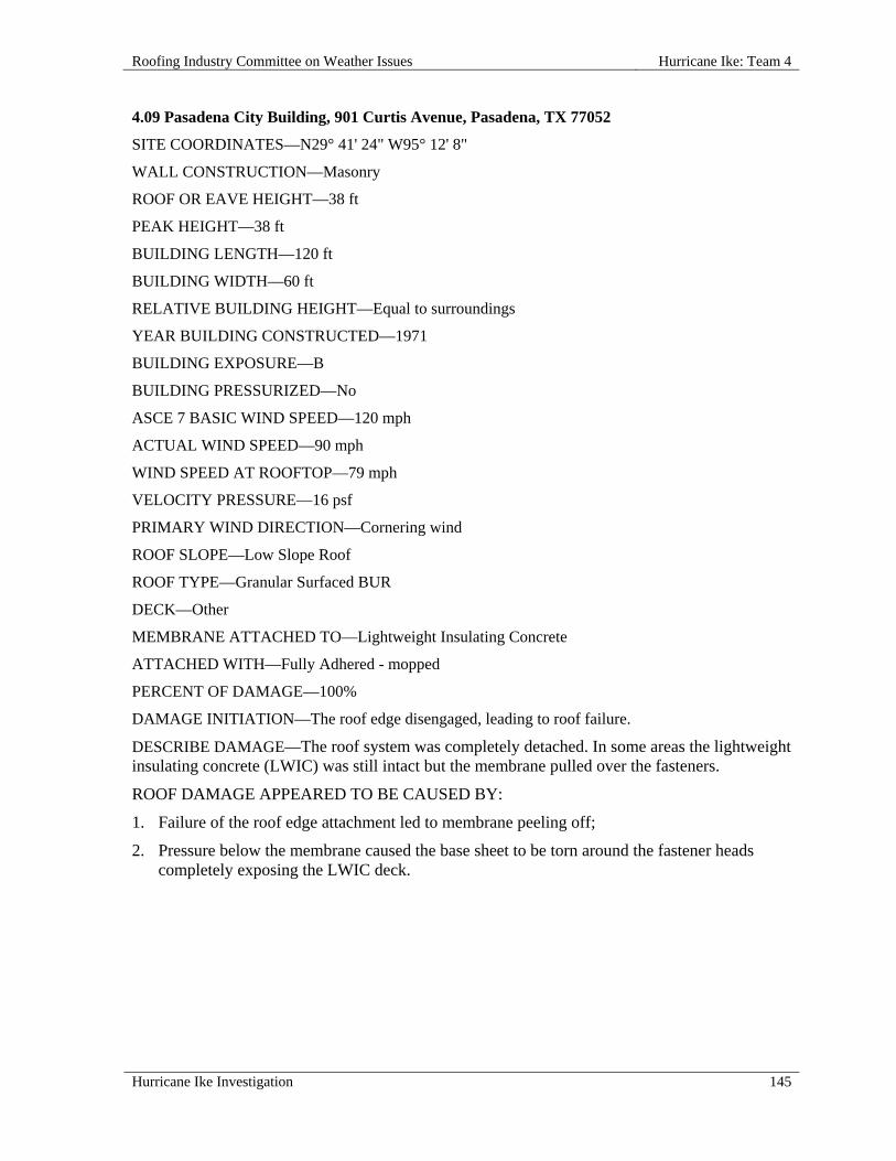
Roofing Industry Committee on Weather Issues Hurricane Ike: Team 4
Hurricane Ike Investigation 145
4.09 Pasadena City Building, 901 Curtis Avenue, Pasadena, TX 77052
SITE COORDINATES—N29° 41' 24" W95° 12' 8"
WALL CONSTRUCTION—Masonry
ROOF OR EAVE HEIGHT—38 ft
PEAK HEIGHT—38 ft
BUILDING LENGTH—120 ft
BUILDING WIDTH—60 ft
RELATIVE BUILDING HEIGHT—Equal to surroundings
YEAR BUILDING CONSTRUCTED—1971
BUILDING EXPOSURE—B
BUILDING PRESSURIZED—No
ASCE 7 BASIC WIND SPEED—120 mph
ACTUAL WIND SPEED—90 mph
WIND SPEED AT ROOFTOP—79 mph
VELOCITY PRESSURE—16 psf
PRIMARY WIND DIRECTION—Cornering wind
ROOF SLOPE—Low Slope Roof
ROOF TYPE—Granular Surfaced BUR
DECK—Other
MEMBRANE ATTACHED TO—Lightweight Insulating Concrete
ATTACHED WITH—Fully Adhered - mopped
PERCENT OF DAMAGE—100%
DAMAGE INITIATION—The roof edge disengaged, leading to roof failure.
DESCRIBE DAMAGE—The roof system was completely detached. In some areas the lightweight insulating concrete (LWIC) was still intact but the membrane pulled over the fasteners.
ROOF DAMAGE APPEARED TO BE CAUSED BY:
1. Failure of the roof edge attachment led to membrane peeling off;
2. Pressure below the membrane caused the base sheet to be torn around the fastener heads completely exposing the LWIC deck.
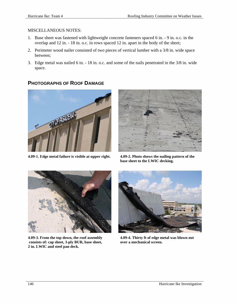
Hurricane Ike: Team 4 Roofing Industry Committee on Weather Issues
146 Hurricane Ike Investigation
MISCELLANEOUS NOTES:
1. Base sheet was fastened with lightweight concrete fasteners spaced 6 in. - 9 in. o.c. in the overlap and 12 in. - 18 in. o.c. in rows spaced 12 in. apart in the body of the sheet;
2. Perimeter wood nailer consisted of two pieces of vertical lumber with a 3/8 in. wide space between;
3. Edge metal was nailed 6 in. - 18 in. o.c. and some of the nails penetrated in the 3/8 in. wide space.
PHOTOGRAPHS OF ROOF DAMAGE
4.09-1. Edge metal failure is visible at upper right. 4.09-2. Photo shows the nailing pattern of the base sheet to the LWIC decking.
4.09-3. From the top down, the roof assembly consists of: cap sheet, 3-ply BUR, base sheet, 2 in. LWIC and steel pan deck.
4.09-4. Thirty ft of edge metal was blown out over a mechanical screen.

Roofing Industry Committee on Weather Issues Hurricane Ike: Team 4
Hurricane Ike Investigation 147
4.09-5. On this double vertical nailer, some nails hit the gap giving them little holding power.
4.09-6. This cleat and fascia were displaced together, with nails 12 in. o.c.
4.10 Pasadena High School, 206 S Shaver Street, Pasadena, TX 77506
SITE COORDINATES—N29° 42' 29" W95° 12' 40"
WALL CONSTRUCTION—Masonry
ROOF OR EAVE HEIGHT—40 ft
PEAK HEIGHT—40 ft
BUILDING LENGTH—235 ft
BUILDING WIDTH—80 ft
RELATIVE BUILDING HEIGHT—Slightly taller than surroundings
NUMBER OF PENETRATIONS GREATER THAN 4 ft x 4 ft x 2 ft HIGH—1
YEAR BUILDING CONSTRUCTED—1940
BUILDING USAGE—High school classrooms
BUILDING EXPOSURE—B
BUILDING PRESSURIZED—No
ASCE 7 BASIC WIND SPEED—110 mph
ACTUAL WIND SPEED—90 mph
WIND SPEED AT ROOFTOP—80 mph
VELOCITY PRESSURE—16 psf
ROOF SLOPE—Low Slope Roof
ROOF TYPE—Mechanically Attached Single Ply
DECK—Concrete
INSULATION TYPE—Polyisocyanurate Foam
INSULATION ATTACHMENT—Screws & plates

Hurricane Ike: Team 4 Roofing Industry Committee on Weather Issues
148 Hurricane Ike Investigation
MEMBRANE—PVC
MEMBRANE ATTACHED TO—Concrete Deck
SURFACE—White
PERCENT OF DAMAGE—>0<10%
DAMAGE INITIATION—Minor damage.
DESCRIBE DAMAGE—A mechanical unit was blown off of its curb.
ROOF DAMAGE APPEARED TO BE CAUSED BY:
1. Excessive winds combined with an inadequately anchored mechanical unit, causing it to tumble across the roof surface.
PHOTOGRAPHS OF ROOF DAMAGE
4.10-1. Front view of the school. 4.10-2. Overview shows drains near a low parapet.
4.10-3. Curb of the displaced mechanical unit. 4.10-4. A curbed mechanical unit covered in plastic.
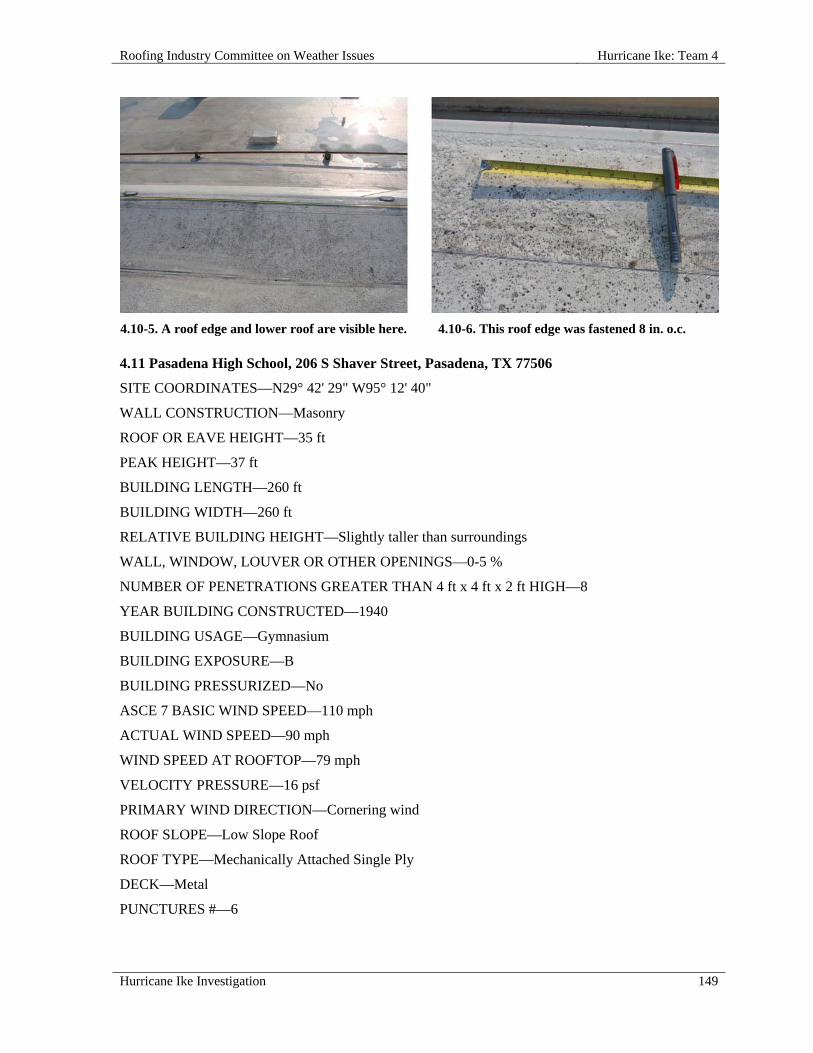
Roofing Industry Committee on Weather Issues Hurricane Ike: Team 4
Hurricane Ike Investigation 149
4.10-5. A roof edge and lower roof are visible here. 4.10-6. This roof edge was fastened 8 in. o.c. 4.11 Pasadena High School, 206 S Shaver Street, Pasadena, TX 77506
SITE COORDINATES—N29° 42' 29" W95° 12' 40"
WALL CONSTRUCTION—Masonry
ROOF OR EAVE HEIGHT—35 ft
PEAK HEIGHT—37 ft
BUILDING LENGTH—260 ft
BUILDING WIDTH—260 ft
RELATIVE BUILDING HEIGHT—Slightly taller than surroundings
WALL, WINDOW, LOUVER OR OTHER OPENINGS—0-5 %
NUMBER OF PENETRATIONS GREATER THAN 4 ft x 4 ft x 2 ft HIGH—8
YEAR BUILDING CONSTRUCTED—1940
BUILDING USAGE—Gymnasium
BUILDING EXPOSURE—B
BUILDING PRESSURIZED—No
ASCE 7 BASIC WIND SPEED—110 mph
ACTUAL WIND SPEED—90 mph
WIND SPEED AT ROOFTOP—79 mph
VELOCITY PRESSURE—16 psf
PRIMARY WIND DIRECTION—Cornering wind
ROOF SLOPE—Low Slope Roof
ROOF TYPE—Mechanically Attached Single Ply
DECK—Metal
PUNCTURES #—6

Hurricane Ike: Team 4 Roofing Industry Committee on Weather Issues
150 Hurricane Ike Investigation
TEARS #—4
INSULATION TYPE—Polyisocyanurate Foam
INSULATION ATTACHMENT—Screws & plates
MEMBRANE—PVC
MEMBRANE ATTACHED TO—Lightweight Insulating Concrete
ATTACHMENT—Perimeter enhancement
SURFACE—White
FASTENER SPACING—8 in.
PERCENT OF DAMAGE—>0<10%
DAMAGE INITIATION—An exhaust hood was dislodged from a curb and tumbled across the roof.
DESCRIBE DAMAGE—The membrane was punctured in several places where a large air-handling unit was blown across the roof.
ROOF DAMAGE APPEARED TO BE CAUSED BY:
1. Excessive winds combined with an inadequately anchored mechanical unit, causing it to tumble across the roof surface.
MISCELLANEOUS NOTES:
1. Corners of this particular roof assembly had full sheets with 6 ft 6 in. fastener row spacing. No efforts were made for corner enhancement. Good design practice requires the use of half sheets or a reduction in fastener spacing for the corner zone where the wind uplift pressures are higher compared to the field of the roof.
PHOTOGRAPHS OF ROOF DAMAGE
4.11-1. Front view of the school. 4.11-2. Overview of the mechanically attached single ply system.

Roofing Industry Committee on Weather Issues Hurricane Ike: Team 4
Hurricane Ike Investigation 151
4.11-3. The mechanical unit is missing from this curb.
4.11-4. Note the trail of puncture repairs across the roof surface.
4.11-5. One of several punctures in the single ply membrane.
4.12 South Houston Intermediate School, 900 College Avenue South, Pasadena, TX 77587
SITE COORDINATES—N29° 39' 35" W95° 14' 25"
ROOF OR EAVE HEIGHT—34 ft
PEAK HEIGHT—40 ft
RELATIVE BUILDING HEIGHT—Equal to surroundings
WALL, WINDOW, LOUVER OR OTHER OPENINGS—5-10%
YEAR BUILDING CONSTRUCTED—1940's
BUILDING USAGE—School
BUILDING EXPOSURE—B
BUILDING PRESSURIZED—No
ASCE 7 BASIC WIND SPEED—110 mph

Hurricane Ike: Team 4 Roofing Industry Committee on Weather Issues
152 Hurricane Ike Investigation
ACTUAL WIND SPEED—90 mph
WIND SPEED AT ROOFTOP—80 mph
VELOCITY PRESSURE—16 psf
ROOF SLOPE—Low Slope Roof
ROOF TYPE—Mechanically Attached Single Ply
DECK—Cementitious Wood Fiber
INSULATION TYPE—Polyisocyanurate Foam
INSULATION THICKNESS—1-1/2 in.
INSULATION ATTACHMENT—Screws & plates
MEMBRANE—PVC
MEMBRANE ATTACHED TO—Lightweight Insulating Concrete
SURFACE—White
PERCENT OF DAMAGE—100%
DAMAGE INITIATION—North edge attachment failed, allowing strong winds to peel roof membranes from the deck.
DESCRIBE DAMAGE—The roof membrane became completely detached from the cementitious wood fiber (CWF) deck. Edge components and wood nailers were also damaged and/or detached. A series of openings where skylights once existed were exposed.
ROOF DAMAGE APPEARED TO BE CAUSED BY:
1. Perimeter nailers pulled free due to poor fastening taking the edging with it;
2. Non-thermal bridging fasteners (NTB) used to secure the roof assembly were too short to properly engage the deck, and were not properly placed in seams.
MISCELLANEOUS NOTES:
1. Roof assembly: 2 in. LWIC poured over 2 in. thick cement fiber deck, 1-1/2 in. polyisocyanurate (ISO), 3-or 4-ply gravel BUR, additional 2 in. of ISO and the PVC single ply membrane;
2. Insulation and base sheet were fastened to the LWIC with staples spaced 18 in. o.c. in rows spaced 12 in. apart; 2 in. insulation layer and membrane were attached with NTB fasteners;
3. 78 in. membrane was fastened 6 in. o.c. in the field splice;
4. Perimeter wood nailer was attached with threaded fasteners spaced 24 in. - 30 in. o.c.;
5. Edge failure exposed a PVC membrane retrofitted over a BUR.

Roofing Industry Committee on Weather Issues Hurricane Ike: Team 4
Hurricane Ike Investigation 153
PHOTOGRAPHS OF ROOF DAMAGE
4.12-1. Front view of the school. 4.12-2. The roof membrane was blown off the upper roof.
4.12-3. Roof assembly components included a PVC membrane, BUR and CWF deck.
4.12-4. Expanded fasteners and staples used for roof assembly securement; screws penetrated PVC, BUR and LWIC, but did not adequately engage the deck.
4.12-5. Edge components still attached to this wood nailer suggest inadequate nailer fastening.
4.12-6. Plastic edging fastener spacing is visible here.

Hurricane Ike: Team 4 Roofing Industry Committee on Weather Issues
154 Hurricane Ike Investigation
4.13 Pasadena Memorial High School, 4410 Crenshaw Street, Pasadena, TX 77504
SITE COORDINATES—N29° 38' 25" W95° 10' 33"
WALL CONSTRUCTION—Masonry
ROOF OR EAVE HEIGHT—35 ft
PEAK HEIGHT—35 ft
BUILDING LENGTH—300 ft
BUILDING WIDTH—165 ft
RELATIVE BUILDING HEIGHT—Slightly taller than surroundings
WALL, WINDOW, LOUVER OR OTHER OPENINGS—10-20%
YEAR BUILDING CONSTRUCTED—2007
BUILDING CODE AT TIME OF CONSTRUCTION—2004
BUILDING USAGE—High school classrooms
BUILDING EXPOSURE—B
BUILDING PRESSURIZED—No
ASCE 7 BASIC WIND SPEED—110 mph
ACTUAL WIND SPEED—90 mph
WIND SPEED AT ROOFTOP—78 mph
VELOCITY PRESSURE—16 psf
PRIMARY WIND DIRECTION—Perpendicular to long side
ROOF SLOPE—Low Slope Roof
ROOF TYPE—Fully Adhered Single Ply
DECK—Concrete
INSULATION TYPE—Polyisocyanurate Foam
MEMBRANE—PVC
MEMBRANE ATTACHED TO—Concrete deck
ATTACHED WITH—Fasteners and plates
SURFACE—White
PERCENT OF DAMAGE—>0<10%
DAMAGE INITIATION—Metal edge.
DESCRIBE DAMAGE—Membrane remained intact even after edge had been dislodged.

Roofing Industry Committee on Weather Issues Hurricane Ike: Team 4
Hurricane Ike Investigation 155
ROOF DAMAGE APPEARED TO BE CAUSED BY:
1. Drip edge face was pulled loose from the building allowing the horizontal flange to be pulled over the fastener heads;
2. First row of membrane securement prevented the spread of damage further into the roof.
MISCELLANEOUS NOTES:
1. Membrane measured 78 in. wide and was attached to the deck with fasteners and plates spaced 12 in. o.c. in the field splices;
2. Three 39 in. wide sheets were utilized around the roof perimeter;
3. Metal drip edge incorporated a 6 in. long face but no cleat; drip edge face was attached with drive-in fasteners (into brick) spaced 24 in. - 30 in. o.c. and the horizontal flange of the drip edge was fastened 8 in. o.c.
PHOTOGRAPHS OF ROOF DAMAGE
4.13-1. Front of the high school. 4.13-2. Overview shows damage to the roof edge.
4.13-3. Damaged edge is inspected. 4.13-4. Photo shows face fastening of edge metal.

Hurricane Ike: Team 4 Roofing Industry Committee on Weather Issues
156 Hurricane Ike Investigation
4.13-5. Face height of metal edge is measured. 4.13-6. Metal edge was fastened 8 in. o.c.

Roofing Industry Committee on Weather Issues Hurricane Ike: Team 6
Hurricane Ike Investigation 157
HURRICANE IKE: TEAM 6
OVERVIEW
Team 6 focused on low slope roof coverings on schools in the greater Houston area. The team
observed 12 roofs at 7 different sites documenting roof construction, wind-damage conditions, and
likely initiation points of the wind damage. All 12 roofs were on low-rise buildings (less than 60 ft
high) in exposure B. Five of the 12 roofs had single ply and seven had built-up and/or modified
bitumen roof coverings. The roofs included fully adhered and mechanically attached membranes.
Roof decks included concrete, steel, wood fiber cement (e.g. Tectum), and lightweight insulating
concrete. Where existing roof coverings appeared to be watertight, collection of information on roof
construction and damage conditions was limited, as no sample cuts were made in the roofing system.
Team Members
The following members participated on Team 6:
Mike Barton, report writer
Pete Garrigus, data recorder
André Desjarlais, sample collector
Phil Dregger, photographer
Summary Observations
Wind-related damage conditions observed on the 12 roofs ranged from minor to extensive. Damage
conditions included loss of edge metal, punctures/tears in roof membranes, withdrawal and pull-over
of securement fasteners, and at some locations complete displacement (blow-off) of the roof system.
Generally speaking, mechanically attached roof membranes appeared to fare better than fully adhered
roof membranes.
The 12 roofs exhibited some commonality in how wind damages began, how damages progressed,
and conditions with which damages were associated.
Events associated with initiation of wind damage included:
a. Winds diverted up and over roof edges lifted the edge metal (cleat deformation and flashing
disengagement) and/or lifted the entire perimeter edge construction, including wood nailers;
b. Air infiltration into spaces below roof membranes billowed near windward roof edges;
c. Windblown debris and wind-toppled equipment punctured/tore roof membranes.
Scenarios regarding how wind damages progressed included:
a. Air infiltrated below roof edge constructions, base sheets pulled over base sheets and/or
fasteners pulled out of the deck, membranes billowed, membranes tore along roof edge, or
lifted entire roof edge construction, and peeled back;
b. Winds accelerating up wall surfaces and over roof edges deformed cleats, bent edge metal
upward, lifted edge metal and/or wood nailers, and then peeled back the roof membrane.
Conditions most often associated with roof covering damage scenarios included:
a. Deteriorated roof attachment systems (resulting in a reduced wind uplift resistance);
b. Corroded fasteners (base sheet, flanged edge metal, and insulation fasteners);
c. Deteriorated wood nailers;
d. Deteriorated lightweight insulating concrete (LWIC) decks (e.g., corroded steel form deck);

Hurricane Ike: Team 6 Roofing Industry Committee on Weather Issues
158 Hurricane Ike Investigation
e. Deteriorated base sheets over LWIC;
f. Roof constructions that varied from common industry recommendations;
g. No increase of mechanical attachment in perimeters or corners;
h. Installing too few base sheet fasteners (1 in. diameter heads) or not utilizing fasteners with
large enough heads (e.g., 2-1/2 in. diameter);
i. Perimeter wood nailer securement less than currently recommended in FM Global LPDS
1-49 and ANSI/SPRI ES-1;
j. Expanding shank or split-shank fasteners that did not expand adequately – re-roofs on LWIC
decks only;
k. Openings that allowed rapid air infiltration between roof membranes and roof decks;
l. Exposure to windborne debris and inadequately anchored mechanical equipment.
Suggestions to enhance wind resistance of roof coverings based on Team 6 observations are included
under the section ―Need for Engineered Design‖ in the Executive Summary.
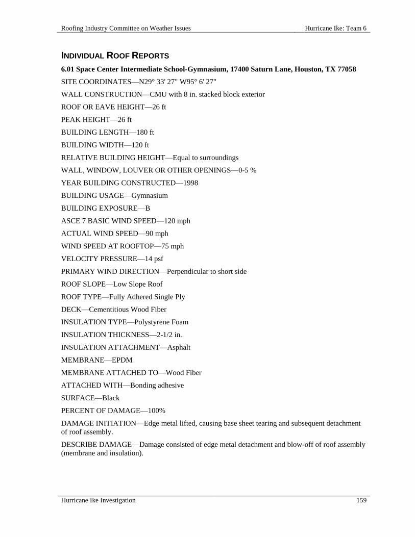
Roofing Industry Committee on Weather Issues Hurricane Ike: Team 6
Hurricane Ike Investigation 159
INDIVIDUAL ROOF REPORTS
6.01 Space Center Intermediate School-Gymnasium, 17400 Saturn Lane, Houston, TX 77058
SITE COORDINATES—N29° 33' 27" W95° 6' 27"
WALL CONSTRUCTION—CMU with 8 in. stacked block exterior
ROOF OR EAVE HEIGHT—26 ft
PEAK HEIGHT—26 ft
BUILDING LENGTH—180 ft
BUILDING WIDTH—120 ft
RELATIVE BUILDING HEIGHT—Equal to surroundings
WALL, WINDOW, LOUVER OR OTHER OPENINGS—0-5 %
YEAR BUILDING CONSTRUCTED—1998
BUILDING USAGE—Gymnasium
BUILDING EXPOSURE—B
ASCE 7 BASIC WIND SPEED—120 mph
ACTUAL WIND SPEED—90 mph
WIND SPEED AT ROOFTOP—75 mph
VELOCITY PRESSURE—14 psf
PRIMARY WIND DIRECTION—Perpendicular to short side
ROOF SLOPE—Low Slope Roof
ROOF TYPE—Fully Adhered Single Ply
DECK—Cementitious Wood Fiber
INSULATION TYPE—Polystyrene Foam
INSULATION THICKNESS—2-1/2 in.
INSULATION ATTACHMENT—Asphalt
MEMBRANE—EPDM
MEMBRANE ATTACHED TO—Wood Fiber
ATTACHED WITH—Bonding adhesive
SURFACE—Black
PERCENT OF DAMAGE—100%
DAMAGE INITIATION—Edge metal lifted, causing base sheet tearing and subsequent detachment
of roof assembly.
DESCRIBE DAMAGE—Damage consisted of edge metal detachment and blow-off of roof assembly
(membrane and insulation).

Hurricane Ike: Team 6 Roofing Industry Committee on Weather Issues
160 Hurricane Ike Investigation
ROOF DAMAGE APPEARED TO BE CAUSED BY:
1. Failure at the edge occurred when fasteners fractured the concrete masonry units(CMUs) and/or
were pulled out of the CMU wall due to excessive wind loading;
2. On windward side of the low parapet wall, fasteners attaching continuous cleats were installed
into CMUs and not wood nailers on the vertical wall face;
3. Sequence of failure was: lifting of edge metal; tearing of base sheet from fasteners/plates;
adhesive failure of EPDM from WFB insulation (see miscellaneous notes for roof assembly
breakdown).
MISCELLANEOUS NOTES:
1. From the roof surface down, the system consisted of:
a. 0.045 in. reinforced EPDM fully adhered with solvent-based adhesive;
b. 1/2 in. wood fiber insulation board hot-mopped with asphalt adhesive to EPS;
c. 2-1/2 in. EPS insulation board hot-mopped with asphalt adhesive to base sheet;
d. #30 felt fastened 12 in. o.c. along side-laps, and 18 in. o.c. in two rows staggered, using
Tube-Lok fasteners with 1 in. diameter integral heads;
e. Loose-laid kraft sheathing paper;
f. 3 in. cementitious wood fiber (CWF) fastened to steel joists with #14 screws and fender
washers (nine each per 2 ft 8 in. x 8 ft 6 in. panel);
2. It was noted that the deck was not sealed at the wall; this may have allowed pressurized air from
the interior to facilitate blow-off of roof membrane.
PHOTOGRAPHS OF ROOF DAMAGE
6.01-1. Aerial view of damage. 6.01-2. View of the building looking eastward.

Roofing Industry Committee on Weather Issues Hurricane Ike: Team 6
Hurricane Ike Investigation 161
6.01-3. EPDM membrane peeled where WFB
mechanically attached.
6.01-4. All snap-on edge metal along southeast
side was displaced. Some metal cleats remained;
some cleat fasteners were positioned in void
space above CMU.
6.01-5. Water damaged flooring inside building. 6.01-6. Openings in deck around drain allowed
air to rapidly enter below the roof covering.
6.01-7. Pattern of fasteners remaining in rosin sheet
after base sheet tore and lifted over fasteners.
6.01-8. WFB only partially adhered to EPS
where hot asphalt was used.

Hurricane Ike: Team 6 Roofing Industry Committee on Weather Issues
162 Hurricane Ike Investigation
6.01-9. Debris field on leeward side of building.
6.02 Space Center Intermediate School-Music, 17400 Saturn Lane, Houston, TX 77058
SITE COORDINATES—N29° 33' 27" W95° 6' 27"
WALL CONSTRUCTION—CMU with 8 in. stacked block exterior
ROOF OR EAVE HEIGHT—20 ft
PEAK HEIGHT—20 ft
BUILDING LENGTH—120 ft
BUILDING WIDTH—64 ft
RELATIVE BUILDING HEIGHT—Equal to surroundings
WALL, WINDOW, LOUVER OR OTHER OPENINGS—0-5 %
YEAR BUILDING CONSTRUCTED—1998
BUILDING USAGE—Music room in school
BUILDING EXPOSURE—B
BUILDING PRESSURIZED—Yes
ASCE 7 BASIC WIND SPEED—120 mph
ACTUAL WIND SPEED—90 mph
WIND SPEED AT ROOFTOP—72 mph
VELOCITY PRESSURE—13 psf
PRIMARY WIND DIRECTION—Perpendicular to short side
ROOF SLOPE—Low Slope Roof
ROOF TYPE—Mechanically Attached Single Ply
DECK—Metal
INSULATION TYPE—Polyisocyanurate Foam
MEMBRANE—EPDM

Roofing Industry Committee on Weather Issues Hurricane Ike: Team 6
Hurricane Ike Investigation 163
MEMBRANE ATTACHED TO—Metal Deck
SURFACE—Black
PLATE SIZE—2 in.
FASTENER ROW SPACING—9 ft 6 in.
PERIMETER ENHANCEMENT—2 rows, 4 ft o.c. @ 6 in. o.c.
PERCENT OF DAMAGE—>0<10%
DAMAGE INITIATION—Damage began and ended at the roof perimeter.
DESCRIBE DAMAGE—Only two 10 ft pieces of metal fascia were blown off.
ROOF DAMAGE APPEARED TO BE CAUSED BY:
1. Wind force exceeded pull-out capability of fasteners.
Metal Attachment:
1. Typical 2 in. plate;
2. Perimeter enhancement: two rows (spaced 4 ft o.c.) of screw and plate fasteners (spaced
6 in. o.c.).
MISCELLANEOUS NOTES:
1. Overall, this roof section appeared to be in excellent condition;
2. The rest of this school complex also appeared to be in very good condition with only a few pieces
of fascia missing.
PHOTOGRAPHS OF ROOF DAMAGE
6.02-1. Overview looking east (1 of 2). 6.02-2. Overview looking east (2 of 2).

Hurricane Ike: Team 6 Roofing Industry Committee on Weather Issues
164 Hurricane Ike Investigation
6.02-3. Elevation view of the southeast side. 6.02-4. Broken light pole.
6.02-5. Panorama from the southeast side (1 of 4). 6.02-6. Panorama from the southeast side (2 of 4).
6.02-7. Panorama from the southeast side (3 of 4). 6.02-8. Panorama from the southeast side (4 of 4).
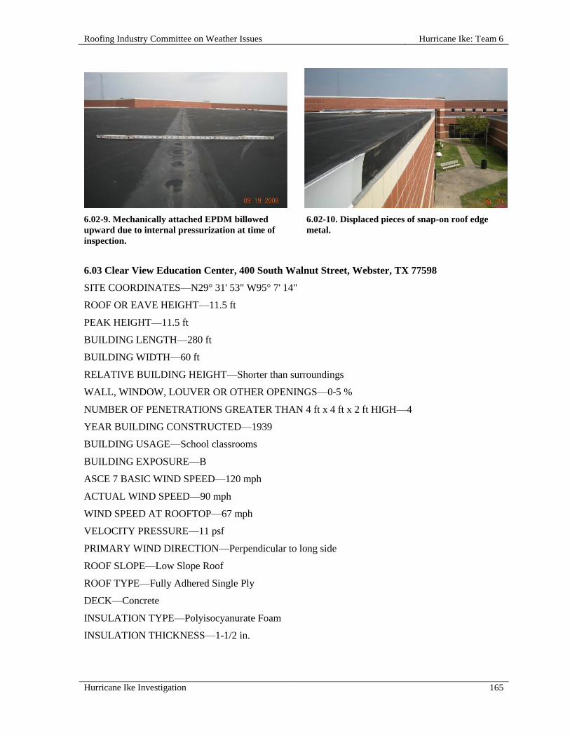
Roofing Industry Committee on Weather Issues Hurricane Ike: Team 6
Hurricane Ike Investigation 165
6.02-9. Mechanically attached EPDM billowed
upward due to internal pressurization at time of
inspection.
6.02-10. Displaced pieces of snap-on roof edge
metal.
6.03 Clear View Education Center, 400 South Walnut Street, Webster, TX 77598
SITE COORDINATES—N29° 31' 53" W95° 7' 14"
ROOF OR EAVE HEIGHT—11.5 ft
PEAK HEIGHT—11.5 ft
BUILDING LENGTH—280 ft
BUILDING WIDTH—60 ft
RELATIVE BUILDING HEIGHT—Shorter than surroundings
WALL, WINDOW, LOUVER OR OTHER OPENINGS—0-5 %
NUMBER OF PENETRATIONS GREATER THAN 4 ft x 4 ft x 2 ft HIGH—4
YEAR BUILDING CONSTRUCTED—1939
BUILDING USAGE—School classrooms
BUILDING EXPOSURE—B
ASCE 7 BASIC WIND SPEED—120 mph
ACTUAL WIND SPEED—90 mph
WIND SPEED AT ROOFTOP—67 mph
VELOCITY PRESSURE—11 psf
PRIMARY WIND DIRECTION—Perpendicular to long side
ROOF SLOPE—Low Slope Roof
ROOF TYPE—Fully Adhered Single Ply
DECK—Concrete
INSULATION TYPE—Polyisocyanurate Foam
INSULATION THICKNESS—1-1/2 in.

Hurricane Ike: Team 6 Roofing Industry Committee on Weather Issues
166 Hurricane Ike Investigation
INSULATION ATTACHMENT—Asphalt
MEMBRANE—EPDM
MEMBRANE ATTACHED TO—Insulation
ATTACHED WITH—Bonding adhesive
SURFACE—Black
PERCENT OF DAMAGE—>75 <100%
DAMAGE INITIATION—Roof edge assembly disengagement led to significant roof membrane
detachment.
DESCRIBE DAMAGE—Roof edge (nailer and metal edge) was damaged, detached, and/or
displaced. Large sections of EPDM membrane became detached (blew off) from insulation. Some
pipes and air handling equipment were also displaced along with the EPDM membrane.
ROOF DAMAGE APPEARED TO BE CAUSED BY:
1. Inadequate Fastening of Roof Edge Assembly - Three #14 screws were used per 14 ft length of
new nailer fastened to existing nailer;
2. Corroded Fasteners – Severe rust was noted on all #14 screws; this appeared to be caused by
galvanic reaction from both dissimilar metals (screws were installed through new nailers and over
existing copper edge) and the close proximity to the existing phenolic insulation (phenolic
insulation is known to cause corrosion in adjacent ferrous metal).
MISCELLANEOUS NOTES:
1. This retrofitted roof assembly was installed around 1998;
2. The roofing assembly consisted of (from the top down):
a. Fully adhered EPDM rubber membrane fully adhered to polyisocyanurate (ISO) insulation
board surface with solvent-based adhesive;
b. Two in. perlite/ISO board (1/2 in. perlite over 1-1/2 in. ISO) hot-mopped to existing roof;
c. Four-ply coal tar pitch built-up roof membrane (BUR) with 1/2 in. embedded crushed stone;
d. Phenolic foam insulation board (1-1/2 in.);
e. Three-ply coal tar pitch BUR;
f. Hollow core concrete deck.

Roofing Industry Committee on Weather Issues Hurricane Ike: Team 6
Hurricane Ike Investigation 167
PHOTOGRAPHS OF ROOF DAMAGE
6.03-1. Aerial view of roof before storm. 6.03-2. Majority of membrane peeled back from
roof edge.
6.03-3. Closer view of photo 6.03-2. 6.03-4. EPDM remained in place below rooftop
conduits.
6.03-5. Displaced wood nailers and edge metal along
southeast side.
6.03-6. Advanced corrosion of screw used to
secure wood nailer.

Hurricane Ike: Team 6 Roofing Industry Committee on Weather Issues
168 Hurricane Ike Investigation
6.03-7. Partially lifted edge metal. Note cleat
secured on top of nailer.
6.03-8. Spacing of nails securing flange of remnant
section of edge metal along southeast side.
6.03-9. Edge metal of photo 6.03-7 lifted to
show severely corroded fasteners.
6.03-10. Overlay- EPDM, ISO insulation, coal tar
BUR, phenolic foam, pre-cast plank.
6.04 Clearview Education Center, 400 South Walnut Street, Webster, TX 77598
SITE COORDINATES—N29° 31' 53" W95° 7' 14"
WALL CONSTRUCTION—Brick veneer
ROOF OR EAVE HEIGHT—30 ft
PEAK HEIGHT—30 ft
BUILDING LENGTH—122 ft
BUILDING WIDTH—72 ft
RELATIVE BUILDING HEIGHT—Equal to surroundings
WALL, WINDOW, LOUVER OR OTHER OPENINGS—0-5 %
YEAR BUILDING CONSTRUCTED—1939
BUILDING USAGE—Gymnasium
BUILDING EXPOSURE—B

Roofing Industry Committee on Weather Issues Hurricane Ike: Team 6
Hurricane Ike Investigation 169
BUILDING PRESSURIZED—Yes
ASCE 7 BASIC WIND SPEED—120 mph
ACTUAL WIND SPEED—90 mph
WIND SPEED AT ROOFTOP—76 mph
VELOCITY PRESSURE—15 psf
PRIMARY WIND DIRECTION—Perpendicular to short side
ROOF SLOPE—Low Slope Roof
ROOF TYPE—Mechanically Attached Single Ply
DECK—Cementitious Wood Fiber
INSULATION TYPE—Polyisocyanurate Foam
INSULATION THICKNESS—3 in.
MEMBRANE—EPDM
MEMBRANE ATTACHED TO—Gypsum Deck
ATTACHMENT—Perimeter enhancement
SURFACE—White
SURFACE COLOR—White coating on black membrane
PLATE SIZE—Batten bar
FASTENER ROW SPACING—9 ft 6 in.
FASTENER SPACING—6 in.
PERIMETER ENHANCEMENT—2 sheets @ 4 ft 8 in. o.c. x 6 in. o.c.
PERCENT OF DAMAGE—>0<10%
DAMAGE INITIATION—No damage.
DESCRIBE DAMAGE—This assembly held up well with little damage noted.
MISCELLANEOUS NOTES:
1. Roof was fastened with Tectum/Auger type fasteners and batten bar;
2. Decking was CWF, 2-3/4 in. thick;
3. This roof assembly was adjacent to the retrofitted EPDM roof listed in investigation 6.03 and was
on the outside border of the campus as well as being one story higher.

Hurricane Ike: Team 6 Roofing Industry Committee on Weather Issues
170 Hurricane Ike Investigation
PHOTOGRAPHS OF ROOF DAMAGE
6.04-1. Overview of roof, 1 of 3. 6.04-2. Overview of roof, 2 of 3.
6.04-3. Overview of roof, 3 of 3. 6.04-4. Roof section at hatch (top to bottom):
single ply (MA), foam plastic insulation, fiber-
cement deck.
6.04-5. Toppled rooftop unit on adjacent roof.

Roofing Industry Committee on Weather Issues Hurricane Ike: Team 6
Hurricane Ike Investigation 171
6.05 Clear Lake High School-9th Grade Center, 2451 E Main Street, Clear Lake, TX 77573
SITE COORDINATES—N29° 31' 39" W95° 4' 24"
WALL CONSTRUCTION—CMU with brick veneer
ROOF OR EAVE HEIGHT—25 ft
PEAK HEIGHT—25 ft
BUILDING LENGTH—330 ft
BUILDING WIDTH—250 ft
OVERHANG LENGTH—180 ft
OVERHANG WIDTH—3 ft
RELATIVE BUILDING HEIGHT—Equal to surroundings
WALL, WINDOW, LOUVER OR OTHER OPENINGS—10-20%
YEAR BUILDING CONSTRUCTED—1982
BUILDING USAGE—School
BUILDING EXPOSURE—B
BUILDING PRESSURIZED—Yes
ASCE 7 BASIC WIND SPEED—120 mph
ACTUAL WIND SPEED—100 mph
WIND SPEED AT ROOFTOP—83 mph
VELOCITY PRESSURE—18 psf
PRIMARY WIND DIRECTION—Perpendicular to long side
ROOF SLOPE—Low Slope Roof
ROOF TYPE—Modified Bitumen
DECK—Metal
PUNCTURES #—3
MEMBRANE ATTACHED TO—Lightweight Insulating Concrete
ATTACHED WITH—Split-shank fasteners
SURFACE—Granules
PERCENT OF DAMAGE—>10<25%
DAMAGE INITIATION—Either the roof edge came loose, membrane detached from the deck, or a
combination of the two.
DESCRIBE DAMAGE—Damaged and/or detached membrane occurred in the field and at roof
edges. Windows also leaked severely.

Hurricane Ike: Team 6 Roofing Industry Committee on Weather Issues
172 Hurricane Ike Investigation
ROOF DAMAGE APPEARED TO BE CAUSED BY:
1. Turbulent Winds and Internal Pressurization - Winds approaching the damage area were likely
accelerated and made quite turbulent by the roofs of the adjacent modular buildings and by the
general roof overhang configuration. Openings in the overhand soffit constructions may have
allowed the space below the roof edge to be pressurized and served to further increase the net
wind uplift forces.
2. Inadequate Construction – Edge nailers were not attached to exterior walls; instead, they appeared
to be cantilevered over exterior walls and mechanically attached to light gauge metal extensions;
the extensions were then attached to the tops of trusses that supported the deck.
MISCELLANEOUS NOTES:
1. A 65 ft x 120 ft section of this roof had been temporarily repaired with non-reinforced EPDM
membrane and ISO insulation board by the time team arrived;
2. The existing roof is approximately one year old and was installed after a complete tear-off of the
previous assembly;
3. Roof failure occurred on the "back side" of the hurricane after the eye had passed over;
4. Another roof in this same building is reported in 6.06.
PHOTOGRAPHS OF ROOF DAMAGE
6.05-1. Aerial view of roof before storm. 6.05-2. Elevation view.
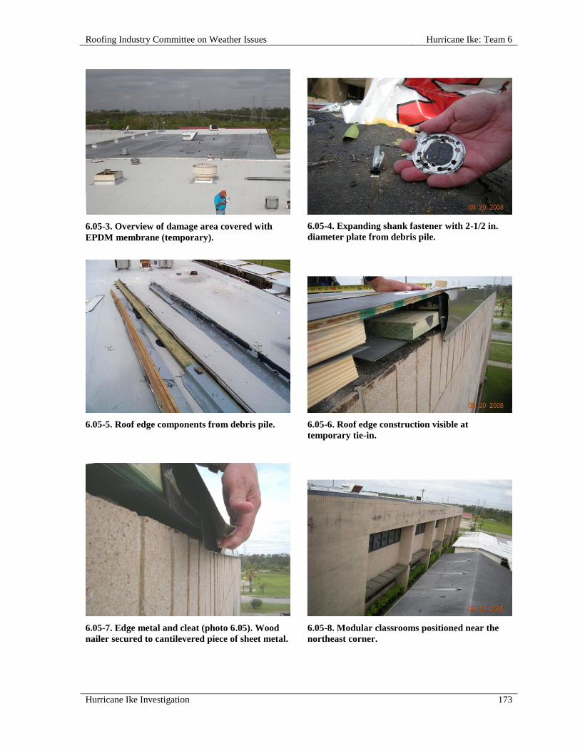
Roofing Industry Committee on Weather Issues Hurricane Ike: Team 6
Hurricane Ike Investigation 173
6.05-3. Overview of damage area covered with
EPDM membrane (temporary).
6.05-4. Expanding shank fastener with 2-1/2 in.
diameter plate from debris pile.
6.05-5. Roof edge components from debris pile. 6.05-6. Roof edge construction visible at
temporary tie-in.
6.05-7. Edge metal and cleat (photo 6.05). Wood
nailer secured to cantilevered piece of sheet metal.
6.05-8. Modular classrooms positioned near the
northeast corner.

Hurricane Ike: Team 6 Roofing Industry Committee on Weather Issues
174 Hurricane Ike Investigation
6.05-9. Louvered vents in soffits located near the
area where damage appears to have started.
6.06 Clear Lake High School-9th Grade Center, 2451 E Main Street, Clear Lake, TX 77573
SITE COORDINATES—N29° 31' 39" W95° 4' 24"
WALL CONSTRUCTION—CMU and brick veneer
ROOF OR EAVE HEIGHT—31 ft
PEAK HEIGHT—31 ft
BUILDING LENGTH—250 ft
BUILDING WIDTH—100 ft
RELATIVE BUILDING HEIGHT—Equal to surroundings
WALL, WINDOW, LOUVER OR OTHER OPENINGS—5-10%
YEAR BUILDING CONSTRUCTED—1982
BUILDING USAGE—School
BUILDING EXPOSURE—B
BUILDING PRESSURIZED—Yes
ASCE 7 BASIC WIND SPEED—120 mph
ACTUAL WIND SPEED—100 mph
WIND SPEED AT ROOFTOP—85 mph
VELOCITY PRESSURE—18 psf
PRIMARY WIND DIRECTION—Perpendicular to long side
ROOF SLOPE—Low Slope Roof
ROOF TYPE—Modified Bitumen
DECK—Metal
SURFACE—Granules
PERCENT OF DAMAGE—>0<10%
DAMAGE INITIATION—No damage.

Roofing Industry Committee on Weather Issues Hurricane Ike: Team 6
Hurricane Ike Investigation 175
DESCRIBE DAMAGE—MISCELLANEOUS NOTES:
1. Although at a higher elevation, this roof surface appeared to be the same as the lower roof
(investigation 6.05);
2. This roof is approximately one year old and was applied after a complete removal of the old
roofing assembly;
3. Perimeter nailer attachment appeared to be different here than on other levels where failure
occurred;
4. Another roof on this same building is reported in 6.05.
PHOTOGRAPHS OF ROOF DAMAGE
6.06-1. South-to-north view of the upper roof
from the southwest corner.
6.06-2. Southwest-to-northeast view of the field
from the southwest corner.
6.06-3. Easterly view from the southwest corner. 6.06-4. East-to-west view from the southeast
corner.

Hurricane Ike: Team 6 Roofing Industry Committee on Weather Issues
176 Hurricane Ike Investigation
6.06-5. Southeast-to-northwest view of the field is
shown from the southeast corner.
6.06-6. Northerly view from the southeast corner.
6.07 Victory Lakes Intermediate School, 2880 West Walker Street, League City, TX 77573
SITE COORDINATES—N29° 28' 29" W95° 5' 18"
WALL CONSTRUCTION—CMU with brick veneer
ROOF OR EAVE HEIGHT—25 ft
PEAK HEIGHT—25 ft
BUILDING LENGTH—300 ft
BUILDING WIDTH—150 ft
RELATIVE BUILDING HEIGHT—Equal to surroundings
WALL, WINDOW, LOUVER OR OTHER OPENINGS—0-5 %
NUMBER OF PENETRATIONS GREATER THAN 4 ft x 4 ft x 2 ft HIGH—5
YEAR BUILDING CONSTRUCTED—2003
BUILDING EXPOSURE—B
BUILDING PRESSURIZED—Yes
ASCE 7 BASIC WIND SPEED—130 mph
ACTUAL WIND SPEED—90 mph
WIND SPEED AT ROOFTOP—74 mph
VELOCITY PRESSURE—14 psf
PRIMARY WIND DIRECTION—Perpendicular to short side
ROOF SLOPE—Low Slope Roof
ROOF TYPE—Mechanically Attached Single Ply
PUNCTURES #—15

Roofing Industry Committee on Weather Issues Hurricane Ike: Team 6
Hurricane Ike Investigation 177
INSULATION TYPE—Polyisocyanurate Foam
INSULATION THICKNESS—4-1/2 in.
MEMBRANE—EPDM
MEMBRANE ATTACHED TO—Metal Deck
ATTACHMENT—Perimeter enhancement
SURFACE—Black
SCREW SIZE—5-1/2 in., #14
PLATE SIZE—Batten Bar
FASTENER ROW SPACING—9 ft 6 in.
FASTENER SPACING—6 in.
PERIMETER ENHANCEMENT—one row @ 4-1/2 ft @ 6 in. o.c.
PERCENT OF DAMAGE—>0<10%
DAMAGE INITIATION—HVAC unit was blown off its curb.
DESCRIBE DAMAGE—This roof assembly appeared to have performed well in the storm. Other
than some damaged edge metal and cover plates, the only other noted damage was an HVAC unit that
was displaced and came to rest downwind of the curb.
ROOF DAMAGE APPEARED TO BE CAUSED BY:
1. Inadequate Attachment of HVAC Unit – This allowed strong winds to blow the unit off the curb;
2. Displaced HVAC Unit – Membrane cuts, holes and damaged edge metal were the result of the
unit tumbling across the roof.
PHOTOGRAPHS OF ROOF DAMAGE
6.07-1. Metal edge above a masonry wall. 6.07-2. The north elevation near the entrance
shows displaced roof edge metal.

Hurricane Ike: Team 6 Roofing Industry Committee on Weather Issues
178 Hurricane Ike Investigation
6.07-3. Photo shows displaced edge metal on
the north elevation near the entrance.
6.07-4. View from the northwest corner.
6.07-5. Another view from the northwest corner. 6.07-6. A prefabricated pipe boot that is
deteriorated and split.
6.07-7. Holes and cuts from wind-blown debris are
visible in this photo.
6.07-8. More holes and cuts from wind-blown
debris are shown here.

Roofing Industry Committee on Weather Issues Hurricane Ike: Team 6
Hurricane Ike Investigation 179
6.07-9. Displaced pieces of snap-on roof edge
metal fascia.
6.08 Horace Mann Junior School, 310 S Highway 146, Baytown, TX 77520
SITE COORDINATES—N29° 43' 29" W94° 57' 32"
ROOF OR EAVE HEIGHT—14 ft
PEAK HEIGHT—14 ft
RELATIVE BUILDING HEIGHT—Equal to surroundings
WALL, WINDOW, LOUVER OR OTHER OPENINGS—0-5 %
YEAR BUILDING CONSTRUCTED—1993
BUILDING USAGE—School
BUILDING EXPOSURE—B
BUILDING PRESSURIZED—Yes
ASCE 7 BASIC WIND SPEED—120 mph
ACTUAL WIND SPEED—110 mph
WIND SPEED AT ROOFTOP—84 mph
VELOCITY PRESSURE—18 psf
PRIMARY WIND DIRECTION—All
ROOF SLOPE—Low Slope Roof
ROOF TYPE—Gravel Surfaced
BUR GRAVEL EMBEDMENT—>25%<50%
PERCENT OF DAMAGE—>0<10%

Hurricane Ike: Team 6 Roofing Industry Committee on Weather Issues
180 Hurricane Ike Investigation
DAMAGE INITIATION—Damage began and apparently ended at roof edges.
DESCRIBE DAMAGE—Only a few pieces of fascia were sprung from cleats, but remained attached.
A small amount of aggregate was found on the driveway below.
ROOF DAMAGE APPEARED TO BE CAUSED BY:
1. Wind forces exceeded strength of cleat attachment.
MISCELLANEOUS NOTES:
1. Overall, this roof looked very good;
2. Aggregate on the roof surface appeared to be firmly embedded in the flood coat;
3. This roof system appeared to be a recent re-roof, as the date of original construction was 1983.
PHOTOGRAPHS OF ROOF DAMAGE
6.08-1. View near the front entrance. 6.08-2. Displaced roof edge metal.
6.08-3. More displaced roof edge metal. 6.08-4. Note the displaced roof edge metal at the
roof corner.
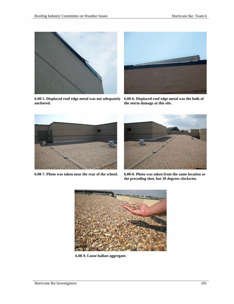
Roofing Industry Committee on Weather Issues Hurricane Ike: Team 6
Hurricane Ike Investigation 181
6.08-5. Displaced roof edge metal was not adequately
anchored.
6.08-6. Displaced roof edge metal was the bulk of
the storm damage at this site.
6.08-7. Photo was taken near the rear of the school. 6.08-8. Photo was taken from the same location as
the preceding shot, but 30 degrees clockwise.
6.08-9. Loose ballast aggregate.

Hurricane Ike: Team 6 Roofing Industry Committee on Weather Issues
182 Hurricane Ike Investigation
6.09 Village Pizza and Seafood, 120 S Alexander Drive, Baytown, TX 77521
SITE COORDINATES—N29° 43' 41" W94° 57' 33"
WALL CONSTRUCTION—Steel stud, stucco
ROOF OR EAVE HEIGHT—16 ft
PEAK HEIGHT—16 ft
BUILDING LENGTH—130 ft
BUILDING WIDTH—70 ft
OVERHANG LENGTH—130 ft
OVERHANG WIDTH—8 ft
RELATIVE BUILDING HEIGHT—Equal to surroundings
WALL, WINDOW, LOUVER OR OTHER OPENINGS—>60%
NUMBER OF PENETRATIONS GREATER THAN 4 ft x 4 ft x 2 ft HIGH—5
YEAR BUILDING CONSTRUCTED—1970's
BUILDING USAGE—Strip mall
BUILDING EXPOSURE—B
BUILDING PRESSURIZED—Yes
ASCE 7 BASIC WIND SPEED—120 mph
ACTUAL WIND SPEED—110 mph
WIND SPEED AT ROOFTOP—85 mph
VELOCITY PRESSURE—18 psf
PRIMARY WIND DIRECTION—Perpendicular to long side
ROOF SLOPE—Low Slope Roof
ROOF TYPE—Modified Bitumen
DECK—Metal
MEMBRANE ATTACHED TO—Lightweight Insulating Concrete
ATTACHED WITH—Nailed
SURFACE—Granules
PERCENT OF DAMAGE—>75 <100%
DAMAGE INITIATION—Not determined.
DESCRIBE DAMAGE—Lightweight insulating concrete (LWIC) decking exhibited advanced
deterioration and in some locations was missing. Approximately 90% of the roof membrane was
separated from the deck. AC units were also dislodged.
It was noted that the deck was in a total failure mode with fist-size pieces of LWIC laying on the
corrugated metal pan deck. The deck gave the appearance of a freshly plowed field.

Roofing Industry Committee on Weather Issues Hurricane Ike: Team 6
Hurricane Ike Investigation 183
ROOF DAMAGE APPEARED TO BE CAUSED BY:
1. This was undetermined, as damage was so complete that few clues remained.
MISCELLANEOUS NOTES:
1. This building had apparently experienced several remodels and had been re-roofed several times;
2. In the last remodel an EIFS mansard was installed, which changed the original roof perimeter
design as well as perimeter attachment;
3. The existing roof is approximately one year old and was applied after complete removal of the
previous assembly.
PHOTOGRAPHS OF ROOF DAMAGE
6.09-1. View looking northeast shows the membrane
hanging from the roof edge.
6.09-2. An inverted roof membrane.
6.09-3. Split-shank LWIC fastener protruding out
of the bottom of displaced portion of roof
membrane.
6.09-4. Overview of the LWIC deck after loss of
roof membrane.
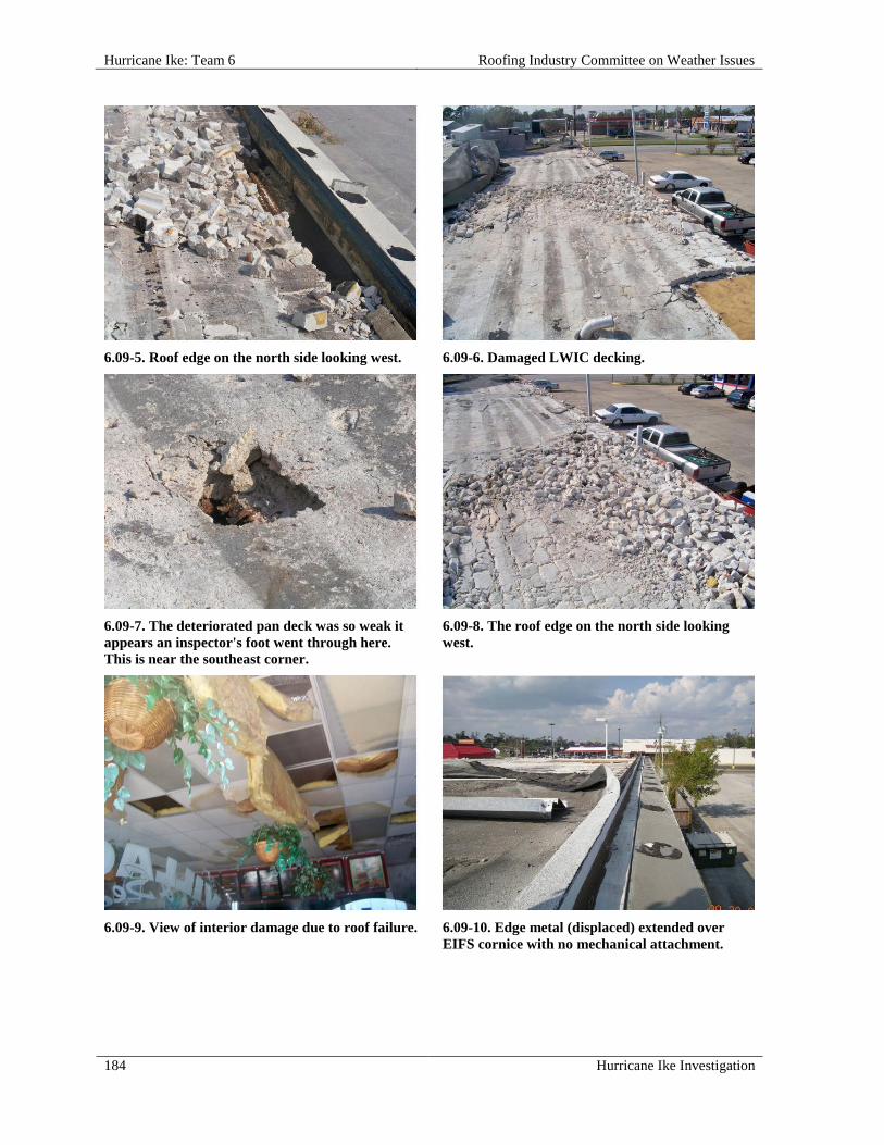
Hurricane Ike: Team 6 Roofing Industry Committee on Weather Issues
184 Hurricane Ike Investigation
6.09-5. Roof edge on the north side looking west. 6.09-6. Damaged LWIC decking.
6.09-7. The deteriorated pan deck was so weak it
appears an inspector's foot went through here.
This is near the southeast corner.
6.09-8. The roof edge on the north side looking
west.
6.09-9. View of interior damage due to roof failure. 6.09-10. Edge metal (displaced) extended over
EIFS cornice with no mechanical attachment.
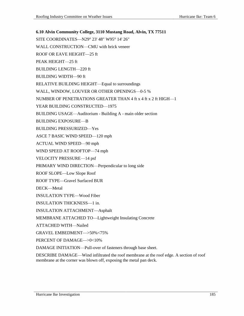
Roofing Industry Committee on Weather Issues Hurricane Ike: Team 6
Hurricane Ike Investigation 185
6.10 Alvin Community College, 3110 Mustang Road, Alvin, TX 77511
SITE COORDINATES—N29° 23' 48" W95° 14' 26"
WALL CONSTRUCTION—CMU with brick veneer
ROOF OR EAVE HEIGHT—25 ft
PEAK HEIGHT—25 ft
BUILDING LENGTH—220 ft
BUILDING WIDTH—90 ft
RELATIVE BUILDING HEIGHT—Equal to surroundings
WALL, WINDOW, LOUVER OR OTHER OPENINGS—0-5 %
NUMBER OF PENETRATIONS GREATER THAN 4 ft x 4 ft x 2 ft HIGH—1
YEAR BUILDING CONSTRUCTED—1975
BUILDING USAGE—Auditorium - Building A - main older section
BUILDING EXPOSURE—B
BUILDING PRESSURIZED—Yes
ASCE 7 BASIC WIND SPEED—120 mph
ACTUAL WIND SPEED—90 mph
WIND SPEED AT ROOFTOP—74 mph
VELOCITY PRESSURE—14 psf
PRIMARY WIND DIRECTION—Perpendicular to long side
ROOF SLOPE—Low Slope Roof
ROOF TYPE—Gravel Surfaced BUR
DECK—Metal
INSULATION TYPE—Wood Fiber
INSULATION THICKNESS—1 in.
INSULATION ATTACHMENT—Asphalt
MEMBRANE ATTACHED TO—Lightweight Insulating Concrete
ATTACHED WITH—Nailed
GRAVEL EMBEDMENT—>50%<75%
PERCENT OF DAMAGE—>0<10%
DAMAGE INITIATION—Pull-over of fasteners through base sheet.
DESCRIBE DAMAGE—Wind infiltrated the roof membrane at the roof edge. A section of roof
membrane at the corner was blown off, exposing the metal pan deck.

Hurricane Ike: Team 6 Roofing Industry Committee on Weather Issues
186 Hurricane Ike Investigation
ROOF DAMAGE APPEARED TO BE CAUSED BY:
1. Poor Edge Fastening – It appears that a recent edge repair had been made, but without first
removing the continuous cleat and edge metal;
2. Wind Infiltration – The repair method mentioned above allowed wind to get under the roof
membrane at the repair spot, facilitating the corner blow-off of the roof membrane; base sheet
fasteners were still fastened to the deck and metal edge was still in place; the base sheet pulled
free of fasteners.
MISCELLANEOUS NOTES:
1. The roof assembly, from the top down, consisted of:
a. Gravel surfaced 4-ply built-up roof membrane (BUR), mopped with hot asphalt;
b. Wood fiber board insulation (1 in.);
c. Base sheet (#30 glass felt) mechanically fastened to the deck;
d. Lightweight insulating concrete (LWIC) over metal pan deck;
e. Base sheet attachment utilized barbed-shank fasteners with 1 in. heads, fastened 18 in. o.c. at
laps, two rows staggered @ 36 in. o.c.; this fastening pattern was used in all areas;
2. It appears that a recent edge repair had been made, but without first removing the
continuous cleat and edge metal; the wind was able to get under the roof membrane at the
repair spot, facilitating the corner blow-off of the roof membrane.
PHOTOGRAPHS OF ROOF DAMAGE
6.10-1. Aerial view with roof area designations. 6.10-2. View east. Note areas where membrane is
displaced near lower left corner.

Roofing Industry Committee on Weather Issues Hurricane Ike: Team 6
Hurricane Ike Investigation 187
6.10-3. Closer view of displaced areas near roof
edge, now covered with plastic sheeting.
6.10-4. Roof level view of damaged areas near roof
edge.
6.10-5. Edge metal remained in place along
displacement area.
6.10-6. Barbed-shank fastener with 1 in. diameter
head. Base sheet pulled over 1 in. head.
6.10-7. Roof edge configuration. Lower L-shaped piece
added later (to stop vermin entry).
6.10-8. Closer view of photo 6.10-7.
Note lower piece not engaged.

Hurricane Ike: Team 6 Roofing Industry Committee on Weather Issues
188 Hurricane Ike Investigation
6.11 Alvin Community College, 3110 Mustang Road, Alvin, TX 77511
SITE COORDINATES—N29° 23' 48" W95° 14' 26"
WALL CONSTRUCTION—CMU with brick veneer
ROOF OR EAVE HEIGHT—25 ft
PEAK HEIGHT—25 ft
BUILDING LENGTH—330 ft
BUILDING WIDTH—120 ft
RELATIVE BUILDING HEIGHT—Equal to surroundings
WALL, WINDOW, LOUVER OR OTHER OPENINGS—0-5 %
YEAR BUILDING CONSTRUCTED—1975
BUILDING USAGE—College - Building A - main newer
BUILDING EXPOSURE—B
BUILDING PRESSURIZED—Yes
ASCE 7 BASIC WIND SPEED—120 mph
ACTUAL WIND SPEED—90 mph
WIND SPEED AT ROOFTOP—74 mph
VELOCITY PRESSURE—14 psf
PRIMARY WIND DIRECTION—Perpendicular to long side
ROOF SLOPE—Low Slope Roof
ROOF TYPE—Gravel Surfaced BUR
DECK—Metal
INSULATION TYPE—Wood Fiber
INSULATION THICKNESS—1 in.
INSULATION ATTACHMENT—Asphalt
MEMBRANE ATTACHED TO—Lightweight Insulating Concrete
ATTACHED WITH—Nailed
GRAVEL EMBEDMENT—>50%<75%
PERCENT OF DAMAGE—>0<10%
DAMAGE INITIATION—Edge failure.
DESCRIBE DAMAGE—Edge Failure precipitated roof damage. A 50 ft x 50 ft section of the
southwest corner was removed and a 20 ft portion of the adjacent roof membrane appeared to have
detached from the substrate. Metal gravel stop and cleats along the damaged area were missing.

Roofing Industry Committee on Weather Issues Hurricane Ike: Team 6
Hurricane Ike Investigation 189
ROOF DAMAGE APPEARED TO BE CAUSED BY:
1. Edge Failure - It appears that when a recent repair was made, the repair was not installed behind
the edge metal and clip, then stripped-in, which facilitated edge failure; instead, the repair was
laminated in hot asphalt to the edge metal that was already in place; this was similar to a repair
(which also failed) detailed in investigation 6.10 at this same site.
MISCELLANEOUS NOTES:
1. This section was covered with plastic tarpaulins and was reportedly repaired recently with the
following base-ply assembly:
a. Base sheet (#30 glass fiber) mechanically fastened with 1.7 in. split-shank LWIC fasteners
having integral 3 in. plates;
b. Base sheet was fastened 12 in. o.c. at laps, and two rows staggered @ 12 in. o.c. down the
middle of the sheets.
PHOTOGRAPHS OF ROOF DAMAGE
6.11-1. Aerial view of roof before storm. 6.11-2. Overview of damage area near windward
corner, 1 of 2.
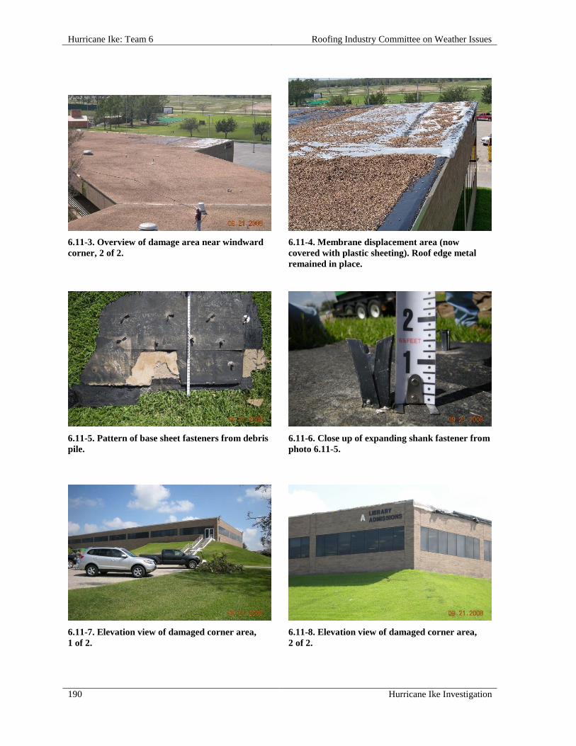
Hurricane Ike: Team 6 Roofing Industry Committee on Weather Issues
190 Hurricane Ike Investigation
6.11-3. Overview of damage area near windward
corner, 2 of 2.
6.11-4. Membrane displacement area (now
covered with plastic sheeting). Roof edge metal
remained in place.
6.11-5. Pattern of base sheet fasteners from debris
pile.
6.11-6. Close up of expanding shank fastener from
photo 6.11-5.
6.11-7. Elevation view of damaged corner area,
1 of 2.
6.11-8. Elevation view of damaged corner area,
2 of 2.
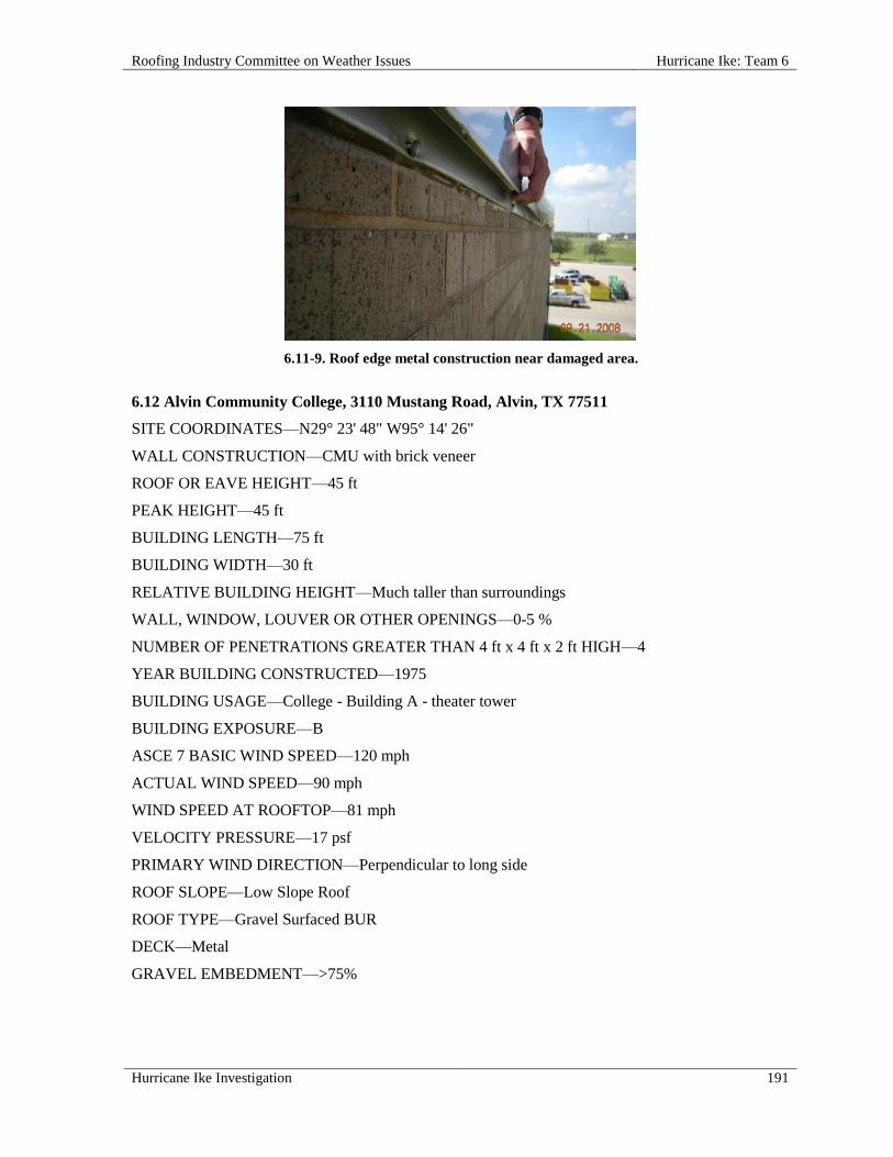
Roofing Industry Committee on Weather Issues Hurricane Ike: Team 6
Hurricane Ike Investigation 191
6.11-9. Roof edge metal construction near damaged area.
6.12 Alvin Community College, 3110 Mustang Road, Alvin, TX 77511
SITE COORDINATES—N29° 23' 48" W95° 14' 26"
WALL CONSTRUCTION—CMU with brick veneer
ROOF OR EAVE HEIGHT—45 ft
PEAK HEIGHT—45 ft
BUILDING LENGTH—75 ft
BUILDING WIDTH—30 ft
RELATIVE BUILDING HEIGHT—Much taller than surroundings
WALL, WINDOW, LOUVER OR OTHER OPENINGS—0-5 %
NUMBER OF PENETRATIONS GREATER THAN 4 ft x 4 ft x 2 ft HIGH—4
YEAR BUILDING CONSTRUCTED—1975
BUILDING USAGE—College - Building A - theater tower
BUILDING EXPOSURE—B
ASCE 7 BASIC WIND SPEED—120 mph
ACTUAL WIND SPEED—90 mph
WIND SPEED AT ROOFTOP—81 mph
VELOCITY PRESSURE—17 psf
PRIMARY WIND DIRECTION—Perpendicular to long side
ROOF SLOPE—Low Slope Roof
ROOF TYPE—Gravel Surfaced BUR
DECK—Metal
GRAVEL EMBEDMENT—>75%

Hurricane Ike: Team 6 Roofing Industry Committee on Weather Issues
192 Hurricane Ike Investigation
PERCENT OF DAMAGE—>75 <100%
DAMAGE INITIATION—Roof edges were the apparent starting point for roof damage.
DESCRIBE DAMAGE—A small amount of edge metal was dislodged. Gravel was scoured severely
on this high roof. No loose gravel was found on this roof plane.
ROOF DAMAGE APPEARED TO BE CAUSED BY:
1. Wind speeds exceeding design limits of edge attachment;
2. Gravel was inadequately embedded to withstand winds of this storm.
PHOTOGRAPHS OF ROOF DAMAGE
6.12-1. Aerial view of roof before storm. 6.12-2. Areas with no aggregate (i.e., wind scour)
near windward corner.
6.12-3. Displaced roof edge metal along one side. See
photo 6.12-4.
6.12-4. Gap at ends of wood nailers (L arrow) and
deformed metal clip (R arrow).

Roofing Industry Committee on Weather Issues Hurricane Ike: Team 7
Hurricane Ike Investigation 193
HURRICANE IKE: TEAM 7
OVERVIEW
Team 7 conducted field reconnaissance of low slope roofing systems primarily in three areas to the east of Houston: Beaumont, Baytown, and eastern suburban Houston. Ten roofs, or sections of roofs, were included in the investigations on buildings having a variety of functions. The types of buildings included a laboratory/office blood bank, a multi-functional industrial shop and office, a college classroom/administrative office, a supermarket warehouse, and several structures at an industrial steel plant which were used for administration, storage, and production. This team had considerable interest in spray polyurethane foam (SPF) roofing and its performance during Hurricane Ike. Past RICOWI post-hurricane reconnaissance (e.g., Hurricane Katrina- Sept. 2005) has shown that such roofing has generally performed well, so the team’s intent was to gather additional data to support past findings. As a consequence, five of the ten roofs inspected had SPF roofing systems. Moreover, considerable effort was made to locate and inspect other SPF roofs in the inspection areas, but without success. The performance of the five SPF roofs was generally satisfactory and, with one exception, no damage was observed. Nevertheless, to place these observations in context, note that many of the low slope roofs in the areas that this team inspected sustained relatively little damage. In this regard, two of the undamaged SPF roofs were directly adjacent to, and on the same buildings as, undamaged bituminous membranes. One was a built-up membrane and the other was a modified bitumen membrane. The five other roofs inspected included two BUR systems; two mechanically attached, thermoplastic, single ply systems; and a composite membrane consisting of modified bitumen ply sheets with an adhered single ply top sheet. Considerable damage had occurred to three of these five roofs (i.e., a BUR, a single ply system, and the composite membrane). The damage is summarized below.
Team Members
The following members participated on Team 7 and were assigned the noted positions, although all assisted significantly in more than one task:
Mason Knowles, observer John Kurtz, photographer Roger Morrison, sample collector Walt Rossiter, report writer, data recorder Robb Smith, photographer
Summary Observations
In the four cases of roof damage observed by the team members, its initiation was typical of that which can occur during high wind events such as hurricanes. The steel plant production facility. The greatest amount (i.e., area) of damage for any of the roofs inspected occurred at the steel plant production facility, which had a gravel surfaced coal tar pitch built-up membrane. This was mainly due to the size of the building, which was estimated to be 1,200,000 sq ft. Although estimates were that less than ten percent of this roof was damaged, the damage area was perhaps on the order of 100,000 sq ft. If only the damaged sections are repaired or replaced, the cost will still be considerable.

Hurricane Ike: Team 7 Roofing Industry Committee on Weather Issues
194 Hurricane Ike Investigation
For this roof, damage was generally considered to have initiated at areas where the membrane and insulation boards were inadequately secured to the deck, whether at the perimeter or in the field of the roof. The insulation attachment methods used on various sections of the roof were minimal mechanical fastening, inadequate strip mopping, or a combination of the two. Rooftop observations recalled instances of insulation-to-steel deck securement that was typical of the 1960s and 1970s. This was not surprising, since the age of the coal tar pitch BUR roof was estimated to be 30 to 40 years. Most of the gravel-stop edge details were undamaged by the wind forces. In one limited area, damaged fascia was observed and attributed to its lack of securement to the building face. This may have contributed to damage of the adjacent membrane and insulation. The college classroom/administrative office building. This was the building having the composite membrane consisting of modified bitumen ply sheets with an adhered single ply top sheet. Re-roofing was under way when the team investigators arrived at the building. Much of the roof had been re-covered after removal of any remaining sections of wind-damaged membrane. Because of the re-roofing, observations of the originally damaged roof were limited. Nevertheless, based on a conversation with a mechanic and observations from a debris pile at the base of the building, evidence on the damage initiation was compiled. In this case, damage was apparently initiated at a failed coping on the windward side of the building. Subsequently, wind penetrated under the membrane, uplifted the membrane, and peeled it from the lightweight concrete substrate. A key observation was that this field-constructed edge detail had a serious defect. In constructing the detail, two 2 in. x 8 in. nailers were face-nailed to each other and were secured to the top of the building wall. Then a 1 in. x 4 in. nailer was nailed to the outer face of these two 2 in. x 8 in. nailers. However, this 1 in. x 4 in. nailer was not well attached, but only fastened to the top 2 in. x 8 in. nailer and only at a spacing of 12 in. to 24 in. When hit by the hurricane winds, this 1 in. x 4 in. nailer seemingly rotated outward and upward, causing release of the coping. Damage to a downwind section of edge detail was also observed and was attributed to blow-off of a mechanical equipment unit. It was considered that this damaged edge detail did not contribute to the loss of the membrane because the detail was located downwind from the major area of membrane damage and the coping-nailer failure. The supermarket warehouse. The roof covering on this building was a mechanically attached, thermoplastic, single ply re-cover system applied over mechanically attached polyisocyanurate (ISO), or perhaps polyurethane, insulation boards. The original membrane was a coal tar BUR system on wood fiber insulation. Like the college building, when the team arrived re-roofing was in progress with much of the re-cover membrane not in place. Presumably, most of the membrane loss was due to the wind forces, as anecdotally relayed by the roofing crew foreman. In the field of the roof, the re-cover insulation was mainly in place over the original BUR system. At the edges, some of these boards were missing, but again the original BUR was in place. For this roof, the mechanism of damage initiation was not determined. The roof-top observations provided evidence that a number of factors may have contributed, but they were not sufficiently definitive for assigning the damage mechanism. These factors were (1) the impact of a blown-off air handler damaging the roof edge, allowing wind penetration; (2) displaced mechanical equipment or equipment covers slicing the membrane, allowing wind penetration; (3) inadequate membrane fastening at the single ply sheet edges and/or corners of the roof, resulting in poor uplift resistance; and (4) a combination of these factors.

Roofing Industry Committee on Weather Issues Hurricane Ike: Team 7
Hurricane Ike Investigation 195
The laboratory/office blood bank. This facility was roofed with an SPF system. The roof survived Hurricane Ike in generally satisfactory condition. The exception was damage to metal fascia at specific sections of the roof edge. These sections corresponded to recesses in the building walls where windows were installed. Neither cleats nor direct mechanical fastening securing the fascia to the wall was observed. Damage initiation was attributed to apparent wind flutter of the unsecured metal fascia, resulting in upward bending or tearing at the roof line.

Hurricane Ike: Team 7 Roofing Industry Committee on Weather Issues
196 Hurricane Ike Investigation
INDIVIDUAL ROOF REPORTS
7.01 Life Share Blood Centers, 4305 Laurel Avenue, Beaumont, TX 77707
SITE COORDINATES—N30° 04' 55" W94° 08' 53"
WALL CONSTRUCTION—Brick facade with glass windows
ROOF OR EAVE HEIGHT—15 ft
PEAK HEIGHT—15 ft
BUILDING LENGTH—97 ft
BUILDING WIDTH—90 ft
RELATIVE BUILDING HEIGHT—Equal to surroundings
WALL, WINDOW, LOUVER OR OTHER OPENINGS—0-5
NUMBER OF PENETRATIONS GREATER THAN 4 ft x 4 ft x 2 ft HIGH—2
YEAR BUILDING CONSTRUCTED—1982
BUILDING USAGE—Office / laboratory
BUILDING EXPOSURE—B
ASCE 7 BASIC WIND SPEED—120 mph
ACTUAL WIND SPEED—90 mph
WIND SPEED AT ROOFTOP—69 mph
VELOCITY PRESSURE—12 psf
PRIMARY WIND DIRECTION—All
ROOF SLOPE—Low Slope Roof
ROOF TYPE—Spray Polyurethane Foam
DECK—Metal pan
INSULATION TYPE—Polyisocyanurate foam with vent board
MEMBRANE ATTACHED TO—Lightweight Insulating Concrete
ATTACHED WITH—Fully Adhered - mopped
SURFACE—Granules
RE-COVER—Yes
PERCENT OF DAMAGE—>0<10%
DAMAGE INITIATION—Perimeter edge metal showed the initial damage.
DESCRIBE DAMAGE—With one exception, this granular surfaced, spray-in-place polyurethane foam (SPF) roofing system was in good condition overall. Metal roof fascia at the window recesses were found to be bent upwards or partially torn at the roof line.

Roofing Industry Committee on Weather Issues Hurricane Ike: Team 7
Hurricane Ike Investigation 197
ROOF DAMAGE APPEARED TO BE CAUSED BY:
1. Apparent wind flutter of unsecured metal fascia resulted in their bending, or tearing at the roof line.
MISCELLANEOUS NOTES:
1. This SPF roofing system was installed in 2001 and was 2 in. thick;
2. Granules consisted of coarse blasting sand, which was undisturbed by the hurricane winds;
3. Building side walls had narrow recesses where windows were located;
4. It was not determined whether cleats were used to secure fascia to side walls.
PHOTOGRAPHS OF ROOF DAMAGE
7.01-1. Indentations along the right edge are evidence of fascia damage.
7.01-2. The SPF in this area appeared to be intact.
7.01-3. In the area of these window recesses, fascia was bent upwards or torn.
7.01-4. This closer view shows metal fascia bent upwards (arrow) at window recess in side wall.

Hurricane Ike: Team 7 Roofing Industry Committee on Weather Issues
198 Hurricane Ike Investigation
7.01-5. Metal fascia was torn along the roof line (arrow) at the corner of the window recess area.
7.02 Energy Service Center, 60 N 11th Street, Beaumont, TX 77702
SITE COORDINATES—N30° 04' 54" W94° 07' 43"
WALL CONSTRUCTION—N & W metal with windows, E attached, S brick
ROOF OR EAVE HEIGHT—18 ft
PEAK HEIGHT—18 ft
BUILDING LENGTH—175 ft
BUILDING WIDTH—45 ft
RELATIVE BUILDING HEIGHT—Equal to surroundings
WALL, WINDOW, LOUVER OR OTHER OPENINGS—0-5 %
NUMBER OF PENETRATIONS GREATER THAN 4 ft x 4 ft x 2 ft HIGH—6
BUILDING USAGE—Office / service center
BUILDING EXPOSURE—B
BUILDING PRESSURIZED—No
ASCE 7 BASIC WIND SPEED—120 mph
ACTUAL WIND SPEED—90 mph
WIND SPEED AT ROOFTOP—71 mph
VELOCITY PRESSURE—13 psf
PRIMARY WIND DIRECTION—All
ROOF SLOPE—Low Slope Roof
ROOF TYPE—Spray Polyurethane Foam
DECK—Metal pan
INSULATION TYPE—Insulating concrete
MEMBRANE ATTACHED TO—Lightweight Insulating Concrete

Roofing Industry Committee on Weather Issues Hurricane Ike: Team 7
Hurricane Ike Investigation 199
ATTACHED WITH—Fully Adhered - mopped
SURFACE—Colored
RE-COVER—Yes
DAMAGE INITIATION—No damage.
DESCRIBE DAMAGE—No damage was observed on this spray-in-place polyurethane foam (SPF) roofing system. RICOWI investigators were informed that a SPF section along the north side of the building had been damaged by Hurricane Rita (Sept. 2005) and subsequently repaired. This patched area was in good condition.
While inspecting the SPF roof, it was noted that the northeast corner of the building had a small section of roof covered with a granular surfaced modified bitumen (MB) system. This MB roof, which was considered as a separate roof section and not examined in detail, also appeared to be in good condition.
MISCELLANEOUS NOTES:
1. The SPF was installed in 1990, and the surface was re-coated in 2006;
2. A second roof at the same site is reported in 7.03.
PHOTOGRAPHS OF ROOF DAMAGE
7.02-1. Overview of the SPF roofing system, which appears to be in good condition.
7.02-2. Another view of the undamaged SPF roof.
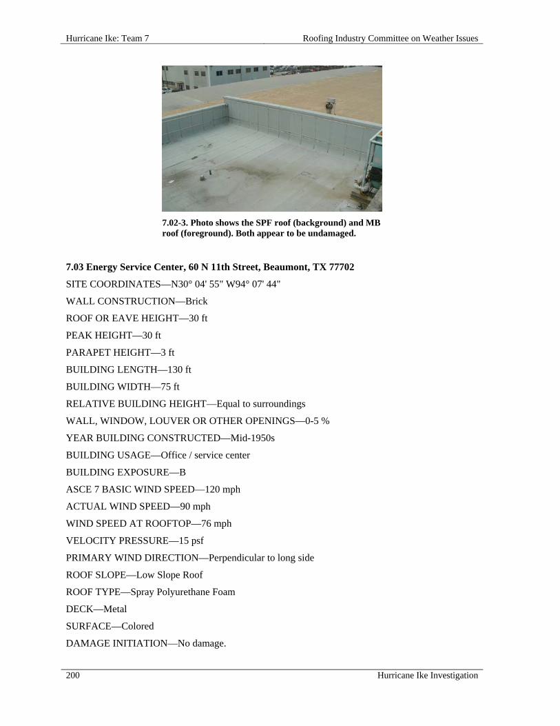
Hurricane Ike: Team 7 Roofing Industry Committee on Weather Issues
200 Hurricane Ike Investigation
7.02-3. Photo shows the SPF roof (background) and MB roof (foreground). Both appear to be undamaged.
7.03 Energy Service Center, 60 N 11th Street, Beaumont, TX 77702
SITE COORDINATES—N30° 04' 55" W94° 07' 44"
WALL CONSTRUCTION—Brick
ROOF OR EAVE HEIGHT—30 ft
PEAK HEIGHT—30 ft
PARAPET HEIGHT—3 ft
BUILDING LENGTH—130 ft
BUILDING WIDTH—75 ft
RELATIVE BUILDING HEIGHT—Equal to surroundings
WALL, WINDOW, LOUVER OR OTHER OPENINGS—0-5 %
YEAR BUILDING CONSTRUCTED—Mid-1950s
BUILDING USAGE—Office / service center
BUILDING EXPOSURE—B
ASCE 7 BASIC WIND SPEED—120 mph
ACTUAL WIND SPEED—90 mph
WIND SPEED AT ROOFTOP—76 mph
VELOCITY PRESSURE—15 psf
PRIMARY WIND DIRECTION—Perpendicular to long side
ROOF SLOPE—Low Slope Roof
ROOF TYPE—Spray Polyurethane Foam
DECK—Metal
SURFACE—Colored
DAMAGE INITIATION—No damage.

Roofing Industry Committee on Weather Issues Hurricane Ike: Team 7
Hurricane Ike Investigation 201
DESCRIBE DAMAGE—Similar to the SPF roof described in 7.02, this spray-in-place polyurethane foam (SPF) roofing system was not damaged by Hurricane Ike.
MISCELLANEOUS NOTES:
1. The system was installed in 1986;
2. Consisted of 2 in. of coated SPF;
3. The coating was aged; considerable bird pecking on the surface was evident;
4. No reported leaks;
5. A second roof at the same site is reported in 7.02.
PHOTOGRAPHS OF ROOF DAMAGE
7.04 Houston Community College-Codwell Hall, 555 Community College Drive, Houston, TX 77013
SITE COORDINATES—N29° 46' 49" W95° 15' 29"
WALL CONSTRUCTION—Metal panels, glass windows
ROOF OR EAVE HEIGHT—45 ft
PEAK HEIGHT—45 ft
PARAPET HEIGHT—1 ft
BUILDING LENGTH—140 ft
BUILDING WIDTH—65 ft
RELATIVE BUILDING HEIGHT—Much taller than surroundings
WALL, WINDOW, LOUVER OR OTHER OPENINGS—20-40%
NUMBER OF PENETRATIONS GREATER THAN 4 ft x 4 ft x 2 ft HIGH—2
YEAR BUILDING CONSTRUCTED—1999
7.03-1. Overview of the SPF roofing system, which was not damaged.
7.03-2. The round dark spots seen on the surface are due to bird pecks and not to any effects from the hurricane.

Hurricane Ike: Team 7 Roofing Industry Committee on Weather Issues
202 Hurricane Ike Investigation
BUILDING USAGE—School
BUILDING EXPOSURE—C
BUILDING PRESSURIZED—Yes
ASCE 7 BASIC WIND SPEED—110 mph
ACTUAL WIND SPEED—90 mph
WIND SPEED AT ROOFTOP—94 mph
VELOCITY PRESSURE—23 psf
PRIMARY WIND DIRECTION—Cornering wind
ROOF SLOPE—Low Slope Roof
ROOF TYPE—Hybrid: Thermoplastic fleece-backed single ply adhered to torch applied modified bitumen (MB) sheet adhered to MB base ply
ATTACHMENT—Base ply was mechanically attached with base ply fasteners
DECK—Metal pan under lightweight insulated concrete
INSULATION TYPE—Insulated concrete deck
RE-COVER—No
PERCENT OF DAMAGE—>75 <100%
DAMAGE INITIATION—The failure apparently started at the northeast perimeter with coping failure.
DESCRIBE DAMAGE—Blow-off of the membrane was considered to have occurred through peeling from the insulating concrete substrate. From the debris pile, it was observed that the fasteners were generally torn from the substrate, remaining embedded in the damaged modified bitumen (MB) membrane.
A mechanical equipment unit was blown off the roof, damaging the edge detail as it fell to the ground below. It did not appear that this damaged edge contributed to the membrane loss.
ROOF DAMAGE APPEARED TO BE CAUSED BY:
1. Failure of Perimeter Detail – Based on examination of a section of coping under repair, inspection of the debris pile, and discussion with roofing workers, roof failure apparently began with damage to the coping detail at the northeast edge of the roof when a 1 in. x 4 in. nailer rotated outward and upward causing release of the coping. Infiltrating wind then lifted the membrane.
2. The failed coping was constructed as follows (from the bottom up):
a. A 2 in. x 8 in. nailer was attached to top of wall (fastening details not determined);
b. A second 2 in. x 8 in. nailer was fastened to the lower one with screws; average spacing was 12 in. o.c. with range of 1 in. - 21 in.; all fasteners were in a single row;
c. A 1 in. x 4 in. nailer was installed with nails perpendicular to the two 2 in. x 8 in. nailers on their outer face; 1 in. x 4 in. nailer was fastened only to the top 2 in. x 8 in. nailer, and only at a spacing of 12 in. - 24 in.;
d. A thermoplastic membrane strip shrouded the nailers and was adhered to the top 2 in. x 8 in. nailer;
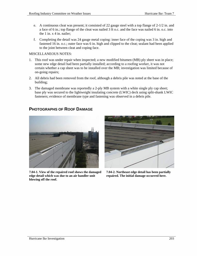
Roofing Industry Committee on Weather Issues Hurricane Ike: Team 7
Hurricane Ike Investigation 203
e. A continuous cleat was present; it consisted of 22 gauge steel with a top flange of 2-1/2 in. and a face of 6 in.; top flange of the cleat was nailed 3 ft o.c. and the face was nailed 6 in. o.c. into the 1 in. x 4 in. nailer;
f. Completing the detail was 24 gauge metal coping: inner face of the coping was 3 in. high and fastened 16 in. o.c.; outer face was 6 in. high and clipped to the cleat; sealant had been applied to the joint between cleat and coping face.
MISCELLANEOUS NOTES:
1. This roof was under repair when inspected; a new modified bitumen (MB) ply sheet was in place; some new edge detail had been partially installed; according to a roofing worker, it was not certain whether a cap sheet was to be installed over the MB; investigation was limited because of on-going repairs;
2. All debris had been removed from the roof, although a debris pile was noted at the base of the building;
3. The damaged membrane was reportedly a 2-ply MB system with a white single ply cap sheet; base ply was secured to the lightweight insulating concrete (LWIC) deck using split-shank LWIC fasteners; evidence of membrane type and fastening was observed in a debris pile.
PHOTOGRAPHS OF ROOF DAMAGE
7.04-1. View of the repaired roof shows the damaged edge detail which was due to an air handler unit blowing off the roof.
7.04-2. Northeast edge detail has been partially repaired. The initial damage occurred here.

Hurricane Ike: Team 7 Roofing Industry Committee on Weather Issues
204 Hurricane Ike Investigation
7.04-3. Debris pile was a result of either hurricane Ike or repair activities.
7.04-4. Note that this damaged 1 in. x 4 in. nailer (from an edge detail) is only fastened into one 2 in. x 8 in. nailer (arrows). No evidence was found of fasteners in a second 2 in. x 8 in. nailer. The second (2 in. x 8 in.) nailer is not visible in this photo.
7.04-5. Damaged nailers from an edge detail. Note that the 1 in. x 4 in. nailer is only fastened into the one 2 in. x 8 in. nailer (arrows). The two nails shown connecting the nailers are 17 in. apart. The second 2 in. x 8 in. nailer is not shown.
7.04-6. Another pile of roofing debris.
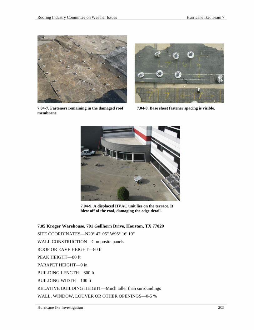
Roofing Industry Committee on Weather Issues Hurricane Ike: Team 7
Hurricane Ike Investigation 205
7.04-9. A displaced HVAC unit lies on the terrace. It blew off of the roof, damaging the edge detail.
7.05 Kroger Warehouse, 701 Gellhorn Drive, Houston, TX 77029
SITE COORDINATES—N29° 47' 05" W95° 16' 19"
WALL CONSTRUCTION—Composite panels
ROOF OR EAVE HEIGHT—80 ft
PEAK HEIGHT—80 ft
PARAPET HEIGHT—9 in.
BUILDING LENGTH—600 ft
BUILDING WIDTH—100 ft
RELATIVE BUILDING HEIGHT—Much taller than surroundings
WALL, WINDOW, LOUVER OR OTHER OPENINGS—0-5 %
7.04-7. Fasteners remaining in the damaged roof membrane.
7.04-8. Base sheet fastener spacing is visible.

Hurricane Ike: Team 7 Roofing Industry Committee on Weather Issues
206 Hurricane Ike Investigation
NUMBER OF PENETRATIONS GREATER THAN 4 ft x 4 ft x 2 ft HIGH—19
YEAR BUILDING CONSTRUCTED—1969
BUILDING USAGE—Warehouse storage
BUILDING EXPOSURE—C
ASCE 7 BASIC WIND SPEED—110 mph
ACTUAL WIND SPEED—90 mph
WIND SPEED AT ROOFTOP—100 mph
VELOCITY PRESSURE—26 psf
PRIMARY WIND DIRECTION—All
ROOF SLOPE—Low Slope Roof
ROOF TYPE—Mechanically Attached Single Ply
TYPE—Hybrid: Nailed asphalt base ply, torch applied mod bit, fleece-backed thermal plastic single-ply (contractor reported it was PVC)
ATTACHMENT—Base ply attached with expandable base ply fasteners into light weight insulating concrete deck; fastening pattern was random
DECK—Metal
INSULATION TYPE—Lightweight concrete
MEMBRANE—Thermoplastic
MEMBRANE ATTACHED TO—Metal Deck
SURFACE—White
SCREW SIZE—No. 12, 6 in.
PLATE SIZE—3 in.
FASTENER ROW SPACING—5 ft
PERIMETER ENHANCEMENT—3 in. from edge, 12 in. o.c.; 21 in. from edge, 12 in. o.c.; 6 ft from edge, 12 in. o.c.
CORNER ENHANCEMENT—Inner corner: 3 in. from edge, 12 in. o.c.; 21 in. from edge, 12 in. o.c.; 6 ft from edge, 12 in. o.c.; Outside corner: 3 in. from edge, 12 in. o.c.; 36 in. from edge, 18–24 in. o.c.; 6 ft from edge, 12 in. o.c.
RE-COVER—No
PERCENT OF DAMAGE—>50<75%
DAMAGE INITIATION—Several factors were considered as having possibly initiated roof damage, but specific causes were not determined.
DESCRIBE DAMAGE—The first retrofitted single ply membrane was missing from almost the entire western half of the roof, presumably due to blow-off. In that blow-off area most re-cover boards were in place in the field, although some were missing. Along roof edges, many of these boards had been lost.

Roofing Industry Committee on Weather Issues Hurricane Ike: Team 7
Hurricane Ike Investigation 207
Edge flashing was mostly intact with the exception of one area that was damaged by a wind-blown air-handling unit. The unit blew off this level and landed on the roof below. The lower roof was damaged by the falling mechanical unit. Other mechanical units were also displaced from their curbs or had lost metal doors/covers.
ROOF DAMAGE APPEARED TO BE CAUSED BY:
1. Damaged Metal Edge - The air handling unit that was blown off an upper level damaged the roof edge, allowing wind penetration into the roof assembly;
2. Impact from Wind-Blown Equipment – Damage on a lower roof was caused by the impact of a mechanical unit falling from an upper level;
3. Poor Fastening - Inadequate membrane fastening technique at the sheet edges and/or corners of the roof resulting in poor uplift resistance.
MISCELLANEOUS NOTES:
1. According to a local contact, the original roof system consisted of a 3-ply coal tar pitch built-up roof membrane (BUR) installed over 2 in. wood fiber insulation board mechanically fastened to a steel deck; subsequent roof examination showed evidence of mopping, as opposed to mechanical fastening;
2. At some point, a new system was retrofitted over the BUR; it consisted of a 35 mil white, reinforced, thermoplastic single ply membrane installed over 1 in. polyurethane foam insulation used as a re-cover board;
3. In center roof section, a second layer of thermoplastic single ply membrane over an unknown recover board was also installed, resulting in three roof systems in place in that area;
4. Re-roofing was in progress at time of inspection so observations were somewhat limited;
5. In one undamaged roof section fastener plate edges were installed flush with, or beyond the edge of, the single ply membrane, instead of stopping 1 in. or more from the membrane edge.
PHOTOGRAPHS OF ROOF DAMAGE
7.05-1. The single ply membrane was blown to this spot from the west side of the building. Note that most of the re-cover boards in the field remained in place (see 7.05-2.).
7.05-2. The recover boards at the west edge of the building were missing, apparently displaced by storm winds.
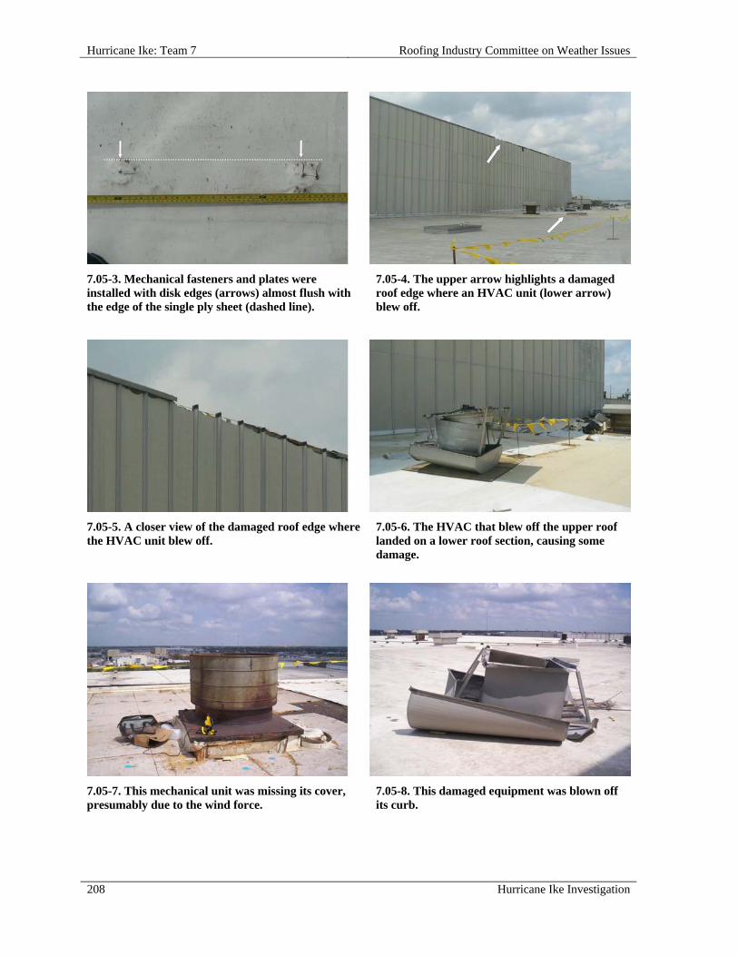
Hurricane Ike: Team 7 Roofing Industry Committee on Weather Issues
208 Hurricane Ike Investigation
7.05-3. Mechanical fasteners and plates were installed with disk edges (arrows) almost flush with the edge of the single ply sheet (dashed line).
7.05-4. The upper arrow highlights a damaged roof edge where an HVAC unit (lower arrow) blew off.
7.05-5. A closer view of the damaged roof edge where the HVAC unit blew off.
7.05-6. The HVAC that blew off the upper roof landed on a lower roof section, causing some damage.
7.05-7. This mechanical unit was missing its cover, presumably due to the wind force.
7.05-8. This damaged equipment was blown off its curb.

Roofing Industry Committee on Weather Issues Hurricane Ike: Team 7
Hurricane Ike Investigation 209
7.06 JSW Steel Administration Building, 5200 E McKinney Road, Baytown, TX 77523
SITE COORDINATES—N29° 41' 47" W94° 54' 00"
WALL CONSTRUCTION—Metal
ROOF OR EAVE HEIGHT—18 ft
PEAK HEIGHT—18 ft
BUILDING LENGTH—280 ft
BUILDING WIDTH—175 ft
OVERHANG LENGTH—20 ft
OVERHANG WIDTH—3 ft
RELATIVE BUILDING HEIGHT—Equal to surroundings
WALL, WINDOW, LOUVER OR OTHER OPENINGS—0-5 %
NUMBER OF PENETRATIONS GREATER THAN 4 ft x 4 ft x 2 ft HIGH—12
YEAR BUILDING CONSTRUCTED—1960s
BUILDING USAGE—Office at industrial plant
BUILDING EXPOSURE—B
ASCE 7 BASIC WIND SPEED—120 mph
ACTUAL WIND SPEED—110 mph
WIND SPEED AT ROOFTOP—87 mph
VELOCITY PRESSURE—19 psf
PRIMARY WIND DIRECTION—All
ROOF SLOPE—Low Slope Roof
ROOF TYPE—Spray Polyurethane Foam
DECK—Metal
SURFACE—White Coated
RE-COVER—Yes
DAMAGE INITIATION—No damage.
DESCRIBE DAMAGE—The age of this sprayed-in-place polyurethane foam (SPF) roof was estimated to be about 15 years. Other roofs at this same location are reported in 7.07, 7.08, 7.09 and 7.10.

Hurricane Ike: Team 7 Roofing Industry Committee on Weather Issues
210 Hurricane Ike Investigation
PHOTOGRAPHS OF ROOF DAMAGE
7.07 JSW Steel, Administration Building, 5200 E. McKinney Road, Baytown, TX 77523
SITE COORDINATES—N29° 41' 49" W94° 54' 00"
WALL CONSTRUCTION—Metal
ROOF OR EAVE HEIGHT—22 ft
PEAK HEIGHT—22 ft
BUILDING LENGTH—160 ft
BUILDING WIDTH—75 ft
RELATIVE BUILDING HEIGHT—Equal to surroundings
WALL, WINDOW, LOUVER OR OTHER OPENINGS—0-5 %
NUMBER OF PENETRATIONS GREATER THAN 4 ft x 4 ft x 2 ft HIGH—7
YEAR BUILDING CONSTRUCTED—1960s
BUILDING USAGE—Office at industrial plant
BUILDING EXPOSURE—B
ASCE 7 BASIC WIND SPEED—120 mph
ACTUAL WIND SPEED—110 mph
WIND SPEED AT ROOFTOP—89 mph
VELOCITY PRESSURE—20 psf
PRIMARY WIND DIRECTION—All
ROOF SLOPE—Low Slope Roof
ROOF TYPE—Granular Surfaced BUR
DECK—Metal
7.06-1. This SPF roofing system was not damaged during Hurricane Ike. The roof showed age, which was estimated to be about 15 years.
7.06-2. This is a different view of the undamaged SPF roofing system.

Roofing Industry Committee on Weather Issues Hurricane Ike: Team 7
Hurricane Ike Investigation 211
DAMAGE INITIATION—No damage.
DESCRIBE DAMAGE—This mineral surfaced built-up roofing system was not damaged during Hurricane Ike. It was located on a section of the same building for which a separate report (7.06) was prepared. Roof age was estimated at 15-20 years. The roof had been extensively patched. Other roofs at this same location are reported in 7.06, 7.08, 7.09 and 7.10.
PHOTOGRAPHS OF ROOF DAMAGE
7.08 JSW Steel, Coating Storage Building, 5200 E McKinney Road, Baytown, TX 77523
SITE COORDINATES—N29° 41' 47" W94° 54' 00" W”
ALL CONSTRUCTION—Metal
ROOF OR EAVE HEIGHT—15 ft
PEAK HEIGHT—15 ft
BUILDING LENGTH—90 ft
BUILDING WIDTH—90 ft
RELATIVE BUILDING HEIGHT—Shorter than surroundings
WALL, WINDOW, LOUVER OR OTHER OPENINGS—0-5 %
NUMBER OF PENETRATIONS GREATER THAN 4 ft x 4 ft x 2 ft HIGH—3
YEAR BUILDING CONSTRUCTED—1960s
BUILDING USAGE—Storage of coating products
BUILDING EXPOSURE—B
ASCE 7 BASIC WIND SPEED—120 mph
ACTUAL WIND SPEED—110 mph
7.07-1. This 15-20 year old built-up roof was not damaged by Hurricane Ike.
7.07-2. Although considered mineral-surfaced, extensive patching had been performed and mineral granules were not always replaced. Note the SPF roof described in report no. 7.06.
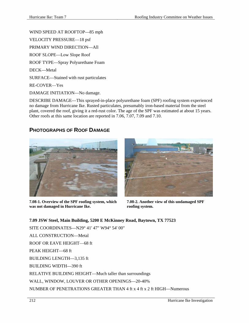
Hurricane Ike: Team 7 Roofing Industry Committee on Weather Issues
212 Hurricane Ike Investigation
WIND SPEED AT ROOFTOP—85 mph
VELOCITY PRESSURE—18 psf
PRIMARY WIND DIRECTION—All
ROOF SLOPE—Low Slope Roof
ROOF TYPE—Spray Polyurethane Foam
DECK—Metal
SURFACE—Stained with rust particulates
RE-COVER—Yes
DAMAGE INITIATION—No damage.
DESCRIBE DAMAGE—This sprayed-in-place polyurethane foam (SPF) roofing system experienced no damage from Hurricane Ike. Rusted particulates, presumably iron-based material from the steel plant, covered the roof, giving it a red-rust color. The age of the SPF was estimated at about 15 years. Other roofs at this same location are reported in 7.06, 7.07, 7.09 and 7.10.
PHOTOGRAPHS OF ROOF DAMAGE
7.09 JSW Steel, Main Building, 5200 E McKinney Road, Baytown, TX 77523
SITE COORDINATES—N29° 41' 47" W94° 54' 00"
ALL CONSTRUCTION—Metal
ROOF OR EAVE HEIGHT—68 ft
PEAK HEIGHT—68 ft
BUILDING LENGTH—3,135 ft
BUILDING WIDTH—390 ft
RELATIVE BUILDING HEIGHT—Much taller than surroundings
WALL, WINDOW, LOUVER OR OTHER OPENINGS—20-40%
NUMBER OF PENETRATIONS GREATER THAN 4 ft x 4 ft x 2 ft HIGH—Numerous
7.08-1. Overview of the SPF roofing system, which was not damaged in Hurricane Ike.
7.08-2. Another view of this undamaged SPF roofing system.
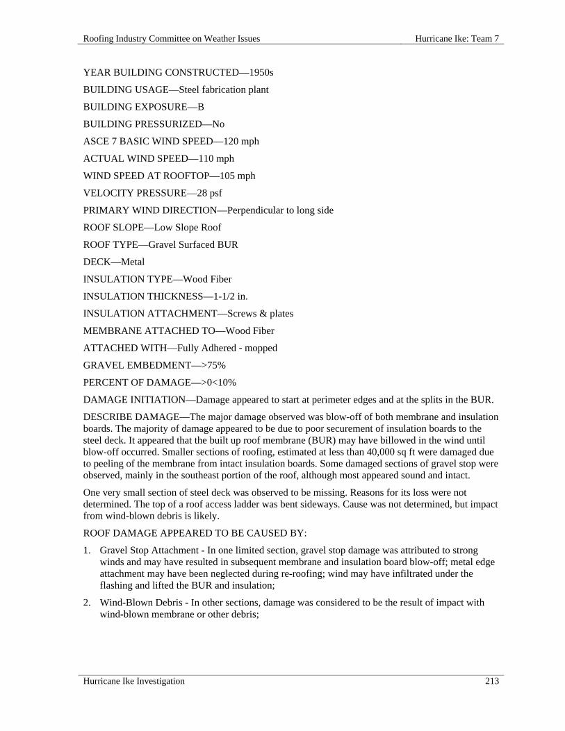
Roofing Industry Committee on Weather Issues Hurricane Ike: Team 7
Hurricane Ike Investigation 213
YEAR BUILDING CONSTRUCTED—1950s
BUILDING USAGE—Steel fabrication plant
BUILDING EXPOSURE—B
BUILDING PRESSURIZED—No
ASCE 7 BASIC WIND SPEED—120 mph
ACTUAL WIND SPEED—110 mph
WIND SPEED AT ROOFTOP—105 mph
VELOCITY PRESSURE—28 psf
PRIMARY WIND DIRECTION—Perpendicular to long side
ROOF SLOPE—Low Slope Roof
ROOF TYPE—Gravel Surfaced BUR
DECK—Metal
INSULATION TYPE—Wood Fiber
INSULATION THICKNESS—1-1/2 in.
INSULATION ATTACHMENT—Screws & plates
MEMBRANE ATTACHED TO—Wood Fiber
ATTACHED WITH—Fully Adhered - mopped
GRAVEL EMBEDMENT—>75%
PERCENT OF DAMAGE—>0<10%
DAMAGE INITIATION—Damage appeared to start at perimeter edges and at the splits in the BUR.
DESCRIBE DAMAGE—The major damage observed was blow-off of both membrane and insulation boards. The majority of damage appeared to be due to poor securement of insulation boards to the steel deck. It appeared that the built up roof membrane (BUR) may have billowed in the wind until blow-off occurred. Smaller sections of roofing, estimated at less than 40,000 sq ft were damaged due to peeling of the membrane from intact insulation boards. Some damaged sections of gravel stop were observed, mainly in the southeast portion of the roof, although most appeared sound and intact.
One very small section of steel deck was observed to be missing. Reasons for its loss were not determined. The top of a roof access ladder was bent sideways. Cause was not determined, but impact from wind-blown debris is likely.
ROOF DAMAGE APPEARED TO BE CAUSED BY:
1. Gravel Stop Attachment - In one limited section, gravel stop damage was attributed to strong winds and may have resulted in subsequent membrane and insulation board blow-off; metal edge attachment may have been neglected during re-roofing; wind may have infiltrated under the flashing and lifted the BUR and insulation;
2. Wind-Blown Debris - In other sections, damage was considered to be the result of impact with wind-blown membrane or other debris;
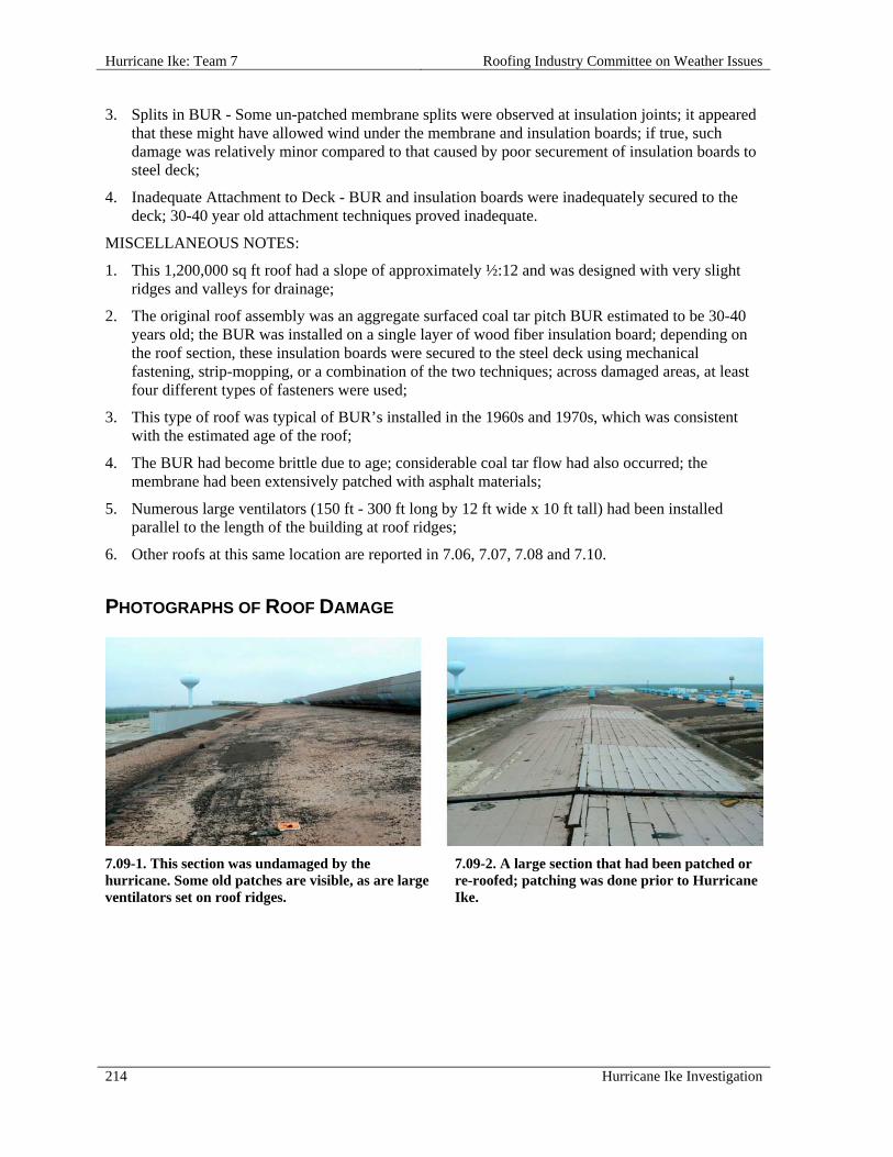
Hurricane Ike: Team 7 Roofing Industry Committee on Weather Issues
214 Hurricane Ike Investigation
3. Splits in BUR - Some un-patched membrane splits were observed at insulation joints; it appeared that these might have allowed wind under the membrane and insulation boards; if true, such damage was relatively minor compared to that caused by poor securement of insulation boards to steel deck;
4. Inadequate Attachment to Deck - BUR and insulation boards were inadequately secured to the deck; 30-40 year old attachment techniques proved inadequate.
MISCELLANEOUS NOTES:
1. This 1,200,000 sq ft roof had a slope of approximately ½:12 and was designed with very slight ridges and valleys for drainage;
2. The original roof assembly was an aggregate surfaced coal tar pitch BUR estimated to be 30-40 years old; the BUR was installed on a single layer of wood fiber insulation board; depending on the roof section, these insulation boards were secured to the steel deck using mechanical fastening, strip-mopping, or a combination of the two techniques; across damaged areas, at least four different types of fasteners were used;
3. This type of roof was typical of BUR’s installed in the 1960s and 1970s, which was consistent with the estimated age of the roof;
4. The BUR had become brittle due to age; considerable coal tar flow had also occurred; the membrane had been extensively patched with asphalt materials;
5. Numerous large ventilators (150 ft - 300 ft long by 12 ft wide x 10 ft tall) had been installed parallel to the length of the building at roof ridges;
6. Other roofs at this same location are reported in 7.06, 7.07, 7.08 and 7.10.
PHOTOGRAPHS OF ROOF DAMAGE
7.09-1. This section was undamaged by the hurricane. Some old patches are visible, as are large ventilators set on roof ridges.
7.09-2. A large section that had been patched or re-roofed; patching was done prior to Hurricane Ike.

Roofing Industry Committee on Weather Issues Hurricane Ike: Team 7
Hurricane Ike Investigation 215
7.09-3. View of damaged corner section BUR and wood fiber insulation board. The gravel stop detail is intact in the area of the blow-off, but one section was bent upward, possibly due to the flexing of the BUR as it was blown from the roof.
7.09-4. A close-up of a damaged corner shown in photo 7.09-3. Note poor attachment of insulation boards due to insufficient fasteners (circles).
7.09-5. Insulation in some areas was secured with fasteners (examples in circles). In other areas, boards were adhered with strip-mopped asphalt. Many fasteners were pulled loose from the steel deck.
7.09-6. A large portion of this roof damage was due to separation of BUR from insulation boards, although some boards also became detached.
7.09-7. Insulation in this area was strip-mopped to the steel deck using hot asphalt. Evidence of mechanical fastening was also observed (examples in circles).
7.09-8. This edge detail by a section of detached roofing may have allowed wind to infiltrate the roof assembly. Insulation boards were mostly mechanically fastened here (examples in circles).

Hurricane Ike: Team 7 Roofing Industry Committee on Weather Issues
216 Hurricane Ike Investigation
7.10 JSW Steel, Main Building, 5200 McKinney Road, Baytown, TX 77523
SITE COORDINATES—N29° 41' 47" W94° 54' 00"
WALL CONSTRUCTION—Metal
ROOF OR EAVE HEIGHT—68 ft
PEAK HEIGHT—68 ft
BUILDING LENGTH—280 ft
BUILDING WIDTH—335 ft
RELATIVE BUILDING HEIGHT—Much taller than surroundings
WALL, WINDOW, LOUVER OR OTHER OPENINGS—20-40%
NUMBER OF PENETRATIONS GREATER THAN 4 ft x 4 ft x 2 ft HIGH—Numerous
YEAR BUILDING CONSTRUCTED—1950s
BUILDING USAGE—Steel fabrication plant
BUILDING EXPOSURE—C
BUILDING PRESSURIZED—No
ASCE 7 BASIC WIND SPEED—120 mph
ACTUAL WIND SPEED—110 mph
WIND SPEED AT ROOFTOP—121 mph
VELOCITY PRESSURE—37 psf
PRIMARY WIND DIRECTION—Perpendicular to long side
ROOF SLOPE—Low Slope Roof
ROOF TYPE—Mechanically Attached Single Ply
DECK—Metal
7.09-9. Evidence was noted of both strip-mopping and mechanical fastening of insulation boards in this area. The use of perlite insulation and different fastening techniques suggested that this area had been previously re-roofed.
7.09-10. Damage to this edge detail was attributed to wind-blown roofing debris.
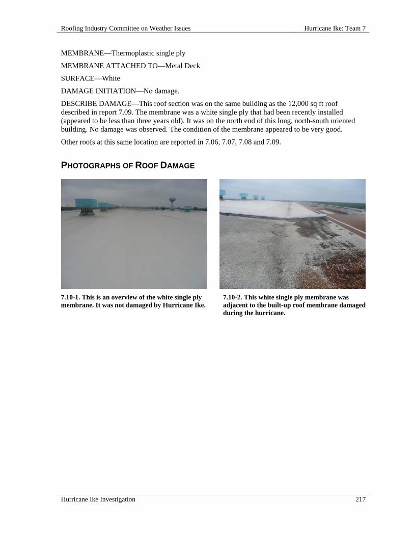
Roofing Industry Committee on Weather Issues Hurricane Ike: Team 7
Hurricane Ike Investigation 217
MEMBRANE—Thermoplastic single ply
MEMBRANE ATTACHED TO—Metal Deck
SURFACE—White
DAMAGE INITIATION—No damage.
DESCRIBE DAMAGE—This roof section was on the same building as the 12,000 sq ft roof described in report 7.09. The membrane was a white single ply that had been recently installed (appeared to be less than three years old). It was on the north end of this long, north-south oriented building. No damage was observed. The condition of the membrane appeared to be very good.
Other roofs at this same location are reported in 7.06, 7.07, 7.08 and 7.09.
PHOTOGRAPHS OF ROOF DAMAGE
7.10-1. This is an overview of the white single ply membrane. It was not damaged by Hurricane Ike.
7.10-2. This white single ply membrane was adjacent to the built-up roof membrane damaged during the hurricane.


Roofing Industry Committee on Weather Issues Hurricane Ike: Team 1
Hurricane Ike Investigation 219
HURRICANE IKE: TEAM 1
OVERVIEW
Team 1 focused on steep slope roof coverings on buildings around the greater Houston area, including the cities of Beaumont, La Porte, League City, and Baytown. The team observed 15 roofs and documented roof construction and wind-damage conditions. Buildings included a church, three hotels, four schools, and seven residential homes. All of these buildings had asphalt shingles. In addition, one street survey was conducted. Team 1 did not inspect any steep roofs other than ones with asphalt shingles. Only a few tile roofs were observed while driving around the observation area, and for those roofs that were damaged, the damage was limited. Team Members
The following members participated on Team 1:
Mike Bryson, photographer Doug Dewey, sample collector Glenn Miller, observer Bill Morgan, report writer, data recorder Bill Woodring, report writer
Summary Observations
Wind related damage conditions observed ranged from minor to severe. Two hotels that were severely damaged were extensively tarped to prevent further water damage. Both had suffered severe water damage because of wind-damaged shingles. Since these roofs had emergency protection we could not access the rooftops but were able to observe shingles that originated from the roofs. Damaged roofs appeared on an intermittent basis. In one area there would be no roof damage, and a mile away there would be some damage to most of the houses in the neighborhood. Usually the shingle damage appeared to be relatively minor. The team saw both application-related issues and some product issues, which were primarily in the form of adhesive not activating. The application issues were more numerous and included, but were not limited to, missing fasteners, high fastener placement, and improper application of starter courses. In general, it was also noted that newer roofs, estimated to be less than five years old, seem to perform much better than the older roofs.

Hurricane Ike: Team 1 Roofing Industry Committee on Weather Issues
220 Hurricane Ike Investigation
INDIVIDUAL ROOF REPORTS
1.01 Falcon Pass Elementary School, 2465 Falcon Pass Drive, Houston, TX 77062
SITE COORDINATES—N29° 34' 35" W95° 06' 37"
WALL CONSTRUCTION—Brick
ROOF OR EAVE HEIGHT—12 ft 9 in.
PEAK HEIGHT—28 ft
OVERHANG WIDTH—1 ft 8 in.
RELATIVE BUILDING HEIGHT—Equal to surroundings
WALL, WINDOW, LOUVER OR OTHER OPENINGS—0-5 %
NUMBER OF PENETRATIONS GREATER THAN 4 ft x 4 ft x 2 ft HIGH—6
YEAR BUILDING CONSTRUCTED—2001
BUILDING USAGE—School
BUILDING EXPOSURE—B
ASCE 7 BASIC WIND SPEED—120 mph
ACTUAL WIND SPEED—100 mph
WIND SPEED AT ROOFTOP—84 mph
VELOCITY PRESSURE—18 psf
ROOF SLOPE—Steep Roof
ROOF TYPE—Asphalt Shingle
TYPE—Architectural
ATTACHMENT—Nails
SECONDARY SUPPORT TYPE—Corrugated metal deck under OSB
NAILS PER SHINGLE—4
DECK—Wood
DECK THICKNESS—7/16 in.
INSULATION TYPE—Polyisocyanurate (ISO) board
INSULATION THICKNESS—3-1/2 in.
UNDERLAYMENT—#15 felt
RE-COVER—No
PERCENT OF DAMAGE—>0<10%
DAMAGE INITIATION—Overhanging shingles at eave and poor fastening of shingles were factors in random shingle blow-off.

Roofing Industry Committee on Weather Issues Hurricane Ike: Team 1
Hurricane Ike Investigation 221
DESCRIBE DAMAGE—80-85% of damage was on the north side. Approximately 15% of ridge shingles were damaged or missing. Intermittent shingle damage was noted on both sides of the ridge on the long run down the center of the building.
Some eave damage included displaced gutters. Eaves had 1-1/2 in. overhang (beyond fascia) which may have been a factor in eave shingle damage.
The gym portion, which was higher than other roof sections, had most of the shingles missing on one side.
ROOF DAMAGE APPEARED TO BE CAUSED BY:
1. “Eave overhang" i.e. shingles extending (overhanging) beyond fascia;
2. 75% of shingles nailed above common bond area of shingle;
3. Previous repairs utilized galvanized metal sheets stuck under shingles, leaving shingles with no seal;
4. Areas at peak of roof encountered high winds, which exceeded shingle sealant holding strength.
MISCELLANEOUS NOTES:
1. 3:12 slope;
2. 0–10% damage;
3. Height: 12 ft 9 in. to bottom of soffit, 13 ft 4 in. to top of soffit;
4. 1-1/4 in. nail (gun nail type);
5. Roof had a ventilated insulated deck.
PHOTOGRAPHS OF ROOF DAMAGE
1.01-1. Site identification. 1.01-2. School aerial view.
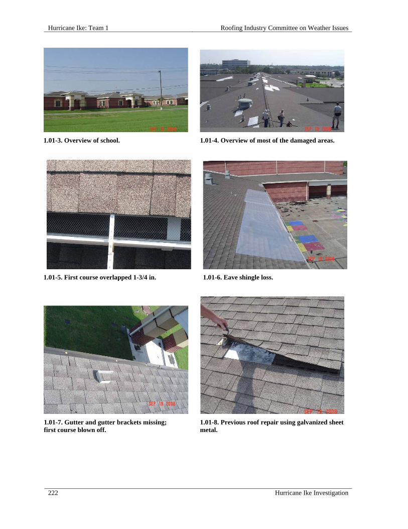
Hurricane Ike: Team 1 Roofing Industry Committee on Weather Issues
222 Hurricane Ike Investigation
1.01-3. Overview of school. 1.01-4. Overview of most of the damaged areas.
1.01-5. First course overlapped 1-3/4 in. 1.01-6. Eave shingle loss.
1.01-7. Gutter and gutter brackets missing; first course blown off.
1.01-8. Previous roof repair using galvanized sheet metal.

Roofing Industry Committee on Weather Issues Hurricane Ike: Team 1
Hurricane Ike Investigation 223
1.01-9. Crooked valley (workmanship). 1.01-10. Three out of four nails placed too high.
1.02 Goforth Elementary School, 2610 Webster Road, League City, TX 77573
SITE COORDINATES—N29° 30' 39" W95° 03' 47"
WALL CONSTRUCTION—Brick
ROOF OR EAVE HEIGHT—13 ft
PEAK HEIGHT—28 ft
OVERHANG WIDTH—1 ft 8 in.
RELATIVE BUILDING HEIGHT—Equal to surroundings
WALL, WINDOW, LOUVER OR OTHER OPENINGS—0-5 %
BUILDING USAGE—School
BUILDING EXPOSURE—B
ASCE 7 BASIC WIND SPEED—120 mph
ACTUAL WIND SPEED—100 mph
WIND SPEED AT ROOFTOP—84 mph
VELOCITY PRESSURE—18 psf
ROOF SLOPE—Steep Roof
ROOF TYPE—Asphalt Shingle
TYPE—Architectural
ATTACHMENT—Nails
NAILS PER SHINGLE—6
UNDERLAYMENT—#15 felt
RE-COVER—No

Hurricane Ike: Team 1 Roofing Industry Committee on Weather Issues
224 Hurricane Ike Investigation
PERCENT OF DAMAGE—>0<10%
DAMAGE INITIATION—Improper fasteners, placement, and placement methods led to shingle blow-off and damage from strong winds from the south.
DESCRIBE DAMAGE—Ridge areas with roofing nails did not blow off, but a hip nailed with standard roofing nails did have some blow-off damage. Most damage was on ridges. One "California closed-cut" valley (cut valley design that has a shingle run vertically up the valley rather than having the shingles cut in the valley) was damaged. Areas of deteriorated deck were noted at eave where blow-off occurred. Areas behind large roof vents had blow-off damage. A large amount of soffit was missing from the south side.
ROOF DAMAGE APPEARED TO BE CAUSED BY:
1. Poor workmanship i.e., some nails were placed through single thickness laminated shingles, while others were overdriven.
MISCELLANEOUS NOTES:
1. Slope changes from 3:12 to near horizontal at drip edge;
2. Metal drip edge on roof;
3. This was the same building design as in inspection 1.01;
4. Some of the ridge course was installed using more common nails than roofing nails.
PHOTOGRAPHS OF ROOF DAMAGE
1.02-1. Site identification. 1.02-2. Aerial view of school.

Roofing Industry Committee on Weather Issues Hurricane Ike: Team 1
Hurricane Ike Investigation 225
1.02-3. School overview. 1.02-4. Overview of roof damage. Most damage occurred up-slope from roof penetrations.
1.02-5. Eave flashing detail. 1.02-6. End nail on shingle; other two nails are raised; shingles are unsealed.
1.02-7. Nails installed too high and located in single thickness of laminated shingle.
1.02-8. Overdriven nails on ridge shingles; nails located in sealant.

Hurricane Ike: Team 1 Roofing Industry Committee on Weather Issues
226 Hurricane Ike Investigation
1.02-9. Shingles damaged up-slope from roof equipment.
1.03 Henry Bauerschlag Elementary School, 2051 Brittany Bay Blvd., League City, TX 77573
SITE COORDINATES—N29° 29' 08" W95° 06' 59"
WALL CONSTRUCTION—Brick
ROOF OR EAVE HEIGHT—13 ft
PEAK HEIGHT—28 ft
OVERHANG WIDTH—1 ft 8 in.
RELATIVE BUILDING HEIGHT—Equal to surroundings
WALL, WINDOW, LOUVER OR OTHER OPENINGS—0-5 %
NUMBER OF PENETRATIONS GREATER THAN 4 ft x 4 ft x 2 ft HIGH—6
BUILDING USAGE—School
BUILDING EXPOSURE—B
BUILDING PRESSURIZED—No
ASCE 7 BASIC WIND SPEED—120 mph
ACTUAL WIND SPEED—100 mph
WIND SPEED AT ROOFTOP—84 mph
VELOCITY PRESSURE—18 psf
ROOF SLOPE—Steep Roof
ROOF TYPE—Asphalt Shingle
TYPE—Architectural
ATTACHMENT—Nails
NAILS PER SHINGLE—6
DECK—Wood
UNDERLAYMENT—#15 felt

Roofing Industry Committee on Weather Issues Hurricane Ike: Team 1
Hurricane Ike Investigation 227
RE-COVER—No
PERCENT OF DAMAGE—>0<10%
DAMAGE INITIATION—Wind uplift damaged improperly applied shingles at eaves.
DESCRIBE DAMAGE—There was very little wind-related damage to trees - probably less wind than at sites 1.01 and 1.02, as well as less damage than the first two. This roof had some blow-off damage around penetrations, but not nearly as much as the first two roofs. Shingles were not consistently sealed. Sealant that was once bonded had failed and the sealant was oxidized. Starter shingles used on the first course were applied with release tape incorrectly lined up with the sealant strip on the first course of shingles and as a result they did not seal.
Two examples were noted where shingle debris was blown between shingles breaking the shingle bond.
ROOF DAMAGE APPEARED TO BE CAUSED BY:
1. Shingle bonds apparently were broken prior to the hurricane, making them more susceptible to wind damage;
2. First course of shingles not sealed to the starter course;
3. Wind-driven debris damage to shingle bonds.
MISCELLANEOUS NOTES:
1. Nail placement appeared to be adequate;
2. Roof slope 3:12;
3. Same design as inspections 1.01 & 1.02;
4. 13 ft 4 in. to top of soffit;
5. In the surrounding neighborhood, many blue protective tarps were noted on residential roofs.
PHOTOGRAPHS OF ROOF DAMAGE
1.03-1. Site identification. 1.03-2. Aerial view of school.

Hurricane Ike: Team 1 Roofing Industry Committee on Weather Issues
228 Hurricane Ike Investigation
1.03-3. First course blow-off; starter course improperly applied so release tape is in contact with sealant.
1.03-4. Starter course with release tape in contact with first course sealant; not sealed.
1.03-5. Some nails were installed too high. Shingle sealant oxidized, which may indicate that shingle sealant released prior to storm.
1.03-6. Hip and ridge shingles nailed too high and/or nailed through sealant.
1.03-7. Shingle debris blown under valley, breaking sealant bond.
1.03-8. Shingle debris blown under shingle, breaking sealant bond.

Roofing Industry Committee on Weather Issues Hurricane Ike: Team 1
Hurricane Ike Investigation 229
1.03-9. Small amount of missing hip and ridge shingles and damaged roof equipment; some equipment is located at far end of parking lot.
1.03-10. Poor nail placement i.e., placed too high, with three nails grouped to one side of shingle.
1.04 Darwin L. Gilmore Elementary School, 3552 Brittany Bay Blvd., League City, TX 77573
SITE COORDINATES—N29° 29' 04" W95° 08' 19"
WALL CONSTRUCTION—Brick
ROOF OR EAVE HEIGHT—13 ft
PEAK HEIGHT—28 ft
OVERHANG WIDTH—1 ft 8 in.
RELATIVE BUILDING HEIGHT—Equal to surroundings
NUMBER OF PENETRATIONS GREATER THAN 4 ft x 4 ft x 2 ft HIGH—6
BUILDING USAGE—School
BUILDING EXPOSURE—B
BUILDING PRESSURIZED—No
ASCE 7 BASIC WIND SPEED—120 mph
ACTUAL WIND SPEED—100 mph
WIND SPEED AT ROOFTOP—84 mph
VELOCITY PRESSURE—18 psf
ROOF SLOPE—Steep Roof
ROOF TYPE—Asphalt Shingle
TYPE—Architectural
ATTACHMENT—Nails
NAILS PER SHINGLE—5-6
DECK—Wood
DECK THICKNESS—5/8 in.
RE-COVER—No

Hurricane Ike: Team 1 Roofing Industry Committee on Weather Issues
230 Hurricane Ike Investigation
PERCENT OF DAMAGE—>0<10%
DAMAGE INITIATION—Shingle damage due to high winds coupled with improper installation techniques.
DESCRIBE DAMAGE—There was very little damage visible from the ground, but some damage and areas of missing (blown off) shingles were noted. Most shingle blow-offs were along the main ridge. Damage above large roof penetrations was also noted (photo 1.04-4). Shingles were nailed incorrectly. These shingles had the option of a "high nail zone" and this is where they were nailed. Shingles that were still adhered were not well sealed i.e., bonds were easily broken. In two places no nails were installed in shingles. In one course over 20 linear ft of shingles had been installed without nails. Some ridge shingles were missing – probably due to overdriven nails. In the field, one section of the first and second courses below the main ridge blew upward, due mainly to lack of adequate seal.
ROOF DAMAGE APPEARED TO BE CAUSED BY:
1. Poor shingle sealing;
2. Missing nails from shingles;
3. Overdriven nails on hip and ridge shingles;
4. Wind turbulence above large roof penetrations.
MISCELLANEOUS NOTES:
1. Roof was in poor condition and may not do well in another high wind event;
2. Roof slope 3:12;
3. The closest neighborhood, across the road from the school, did not appear to have any roof, tree, or fence damage.
PHOTOGRAPHS OF ROOF DAMAGE
1.04-1. Site identification. 1.04-2. Aerial view of school.
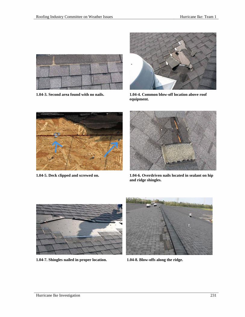
Roofing Industry Committee on Weather Issues Hurricane Ike: Team 1
Hurricane Ike Investigation 231
1.04-3. Second area found with no nails. 1.04-4. Common blow-off location above roof equipment.
1.04-5. Deck clipped and screwed on. 1.04-6. Overdriven nails located in sealant on hip and ridge shingles.
1.04-7. Shingles nailed in proper location. 1.04-8. Blow-offs along the ridge.

Hurricane Ike: Team 1 Roofing Industry Committee on Weather Issues
232 Hurricane Ike Investigation
1.04-9. Unsealed sealant dots.
1.05 Residence, 11433 Davidson Road, Beaumont, TX 77705
SITE COORDINATES—N29° 54' 55" W94° 05' 25"
ROOF OR EAVE HEIGHT—8 ft
PEAK HEIGHT—20 ft
BUILDING LENGTH—64 ft
BUILDING WIDTH—54 ft
OVERHANG WIDTH—1 ft
RELATIVE BUILDING HEIGHT—Equal to surroundings
WALL, WINDOW, LOUVER OR OTHER OPENINGS—5-10%
YEAR BUILDING CONSTRUCTED—1999
BUILDING USAGE—Residence
BUILDING EXPOSURE—B
BUILDING PRESSURIZED—No
ASCE 7 BASIC WIND SPEED—120 mph
ACTUAL WIND SPEED—100 mph
WIND SPEED AT ROOFTOP—80 mph
VELOCITY PRESSURE—16 psf
ROOF SLOPE—Steep Roof
ROOF TYPE—Asphalt Shingle
TYPE—Architectural
ATTACHMENT—Nails
NAILS PER SHINGLE—4
DECK—Wood

Roofing Industry Committee on Weather Issues Hurricane Ike: Team 1
Hurricane Ike Investigation 233
RE-COVER—No
PERCENT OF DAMAGE—>10<25%
DAMAGE INITIATION—Improper nailing and lack of effective seal where Hurricane Rita (September 2005) repair was tied in.
DESCRIBE DAMAGE—Visible damage included this house, neighbor's large garage, a small metal storage building, and some nearby trees. Houses next door and across the street did not have any visible roof or tree damage. Approximately 10-25% of the roof was damaged. Most damage was on the northeast side with some damage on the southwest side. This roof was repaired after damage from Hurricane Rita and that damage may have contributed to the blow-off.
Major blow-off areas and hip/ridge areas had nails placed too high. Tie-in course was not properly sealed. Some replacement shingles were sealed at top/middle of shingle so tie-in end did not have contact with underlying shingle.
Old shingles had self-seal strip located 2 in. above butt edges. Replacement shingles had self-seal strips located 3/4 in. above butt edges. Mismatched seals appear to have contributed to shingle displacement from high winds.
ROOF DAMAGE APPEARED TO BE CAUSED BY:
1. Differing shingle types ineffectively tied together; tie-in of shingles used for previous roof repairs (from Hurricane Rita) was poor because shingles with self-seal strips located indifferent places did not achieve adequate seals;
2. Old shingles' sealant bond was located 2 in. up from leading edge, a location no longer used due to poor high wind performance;
3. Hip and ridge shingles were nailed in sealant; sealant had weak bond strength;
4. Shingles were nailed above the common bond nail zone;
5. Damage may have been the result of a tornado rather than hurricane winds.
MISCELLANEOUS NOTES:
1. Owner reported 110 mph winds;
2. Roof slope ranged from 6:12 to 8:12;
3. OSB deck;
4. House was in a storm surge area (approx. 18 in. deep).

Hurricane Ike: Team 1 Roofing Industry Committee on Weather Issues
234 Hurricane Ike Investigation
PHOTOGRAPHS OF ROOF DAMAGE
1.05-1. Site identification. 1.05-2. Overall view of the home.
1.05-3. Nails placed above nailing area. 1.05-4. Improper nail location; hip and ridge shingle with nails located in sealant; sealant had a poor seal.
1.05-5. Nailed only on one end from the valley; different shingles from repairs after Hurricane Rita.
1.05-6. Sealant located 2 in. above leading edge.
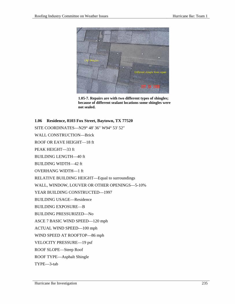
Roofing Industry Committee on Weather Issues Hurricane Ike: Team 1
Hurricane Ike Investigation 235
1.05-7. Repairs are with two different types of shingles; because of different sealant locations some shingles were not sealed.
1.06 Residence, 8103 Fox Street, Baytown, TX 77520
SITE COORDINATES—N29° 48' 36" W94° 53' 52"
WALL CONSTRUCTION—Brick
ROOF OR EAVE HEIGHT—18 ft
PEAK HEIGHT—33 ft
BUILDING LENGTH—40 ft
BUILDING WIDTH—42 ft
OVERHANG WIDTH—1 ft
RELATIVE BUILDING HEIGHT—Equal to surroundings
WALL, WINDOW, LOUVER OR OTHER OPENINGS—5-10%
YEAR BUILDING CONSTRUCTED—1997
BUILDING USAGE—Residence
BUILDING EXPOSURE—B
BUILDING PRESSURIZED—No
ASCE 7 BASIC WIND SPEED—120 mph
ACTUAL WIND SPEED—100 mph
WIND SPEED AT ROOFTOP—86 mph
VELOCITY PRESSURE—19 psf
ROOF SLOPE—Steep Roof
ROOF TYPE—Asphalt Shingle
TYPE—3-tab
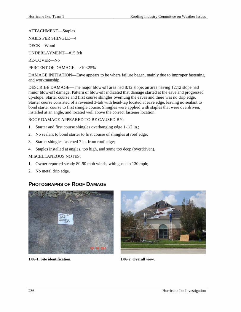
Hurricane Ike: Team 1 Roofing Industry Committee on Weather Issues
236 Hurricane Ike Investigation
ATTACHMENT—Staples
NAILS PER SHINGLE—4
DECK—Wood
UNDERLAYMENT—#15 felt
RE-COVER—No
PERCENT OF DAMAGE—>10<25%
DAMAGE INITIATION—Eave appears to be where failure began, mainly due to improper fastening and workmanship.
DESCRIBE DAMAGE—The major blow-off area had 8:12 slope; an area having 12:12 slope had minor blow-off damage. Pattern of blow-off indicated that damage started at the eave and progressed up-slope. Starter course and first course shingles overhung the eaves and there was no drip edge. Starter course consisted of a reversed 3-tab with head-lap located at eave edge, leaving no sealant to bond starter course to first shingle course. Shingles were applied with staples that were overdriven, installed at an angle, and located well above the correct fastener location.
ROOF DAMAGE APPEARED TO BE CAUSED BY:
1. Starter and first course shingles overhanging edge 1-1/2 in.;
2. No sealant to bond starter to first course of shingles at roof edge;
3. Starter shingles fastened 7 in. from roof edge;
4. Staples installed at angles, too high, and some too deep (overdriven).
MISCELLANEOUS NOTES:
1. Owner reported steady 80-90 mph winds, with gusts to 130 mph;
2. No metal drip edge.
PHOTOGRAPHS OF ROOF DAMAGE
1.06-1. Site identification. 1.06-2. Overall view.

Roofing Industry Committee on Weather Issues Hurricane Ike: Team 1
Hurricane Ike Investigation 237
1.06-3. First course blow-off with starter course staying intact. Starter course is improperly applied so there is no sealant to make contact with first course.
1.06-4. Staples placed above nailing area and angled. Some staples were overdriven.
1.06-5. Starter course fastened high and with too much overhang. Sealant is too high up on starter course to be effective.
1.06-6. Depicts a well sealed shingle.
1.07 Marriott Residence Inn, 655 N Sam Houston Parkway, Houston, TX 77060
SITE COORDINATES—N29° 56' 24" W95° 29' 24"
WALL CONSTRUCTION—Siding
ROOF OR EAVE HEIGHT—27 ft
PEAK HEIGHT—36 ft
RELATIVE BUILDING HEIGHT—Equal to surroundings
BUILDING USAGE—Hotel
BUILDING EXPOSURE—B
BUILDING PRESSURIZED—No
ASCE 7 BASIC WIND SPEED—100 mph

Hurricane Ike: Team 1 Roofing Industry Committee on Weather Issues
238 Hurricane Ike Investigation
ACTUAL WIND SPEED—90 mph
WIND SPEED AT ROOFTOP—78 mph
VELOCITY PRESSURE—16 psf
ROOF SLOPE—Steep Roof
ROOF TYPE—Asphalt Shingle
TYPE—Architectural
ATTACHMENT—Nails
NAILS PER SHINGLE—4
RE-COVER—No
PERCENT OF DAMAGE—>10<25%
DAMAGE INITIATION—Improper installation and loss of seal left shingles susceptible to blow-off damage.
DESCRIBE DAMAGE—Judging from placement of protective tarps, most damage was along both sides of ridge, although some was in valleys. Hotel required complete renovation (all three floors) due to water damage from roof.
ROOF DAMAGE APPEARED TO BE CAUSED BY:
1. Either poor sealant bond or sealant that was bonded released; shingle sealant oxidized. The cause of why the shingles were not sealed before this investigation could not be determined. There was evidence that either the shingles had never sealed due to the formulation of the sealant, cool weather application and/or dusty conditions. Another possibility is that the seal was broken by physical force or a wind event prior to Hurricane Ike.
2. Nails were located above the common bond nail zone.
MISCELLANEOUS NOTES:
1. Shingle size: 13-1/4 in. x 38-1/2 in.;
2. The hotel next door had very little damage; this building was also located on the north side of Houston;
3. Damage may have resulted from a tornado within the hurricane.

Roofing Industry Committee on Weather Issues Hurricane Ike: Team 1
Hurricane Ike Investigation 239
PHOTOGRAPHS OF ROOF DAMAGE
1.07-1. Site identification. 1.07-2. Overall view of hotel.
1.07-3. Another view of the hotel. 1.07-4. Nails are located above nailing area.
1.07-5. Intermittent sealant and "high-nailing." 1.07-6. Lack of seal on this area on shingle.
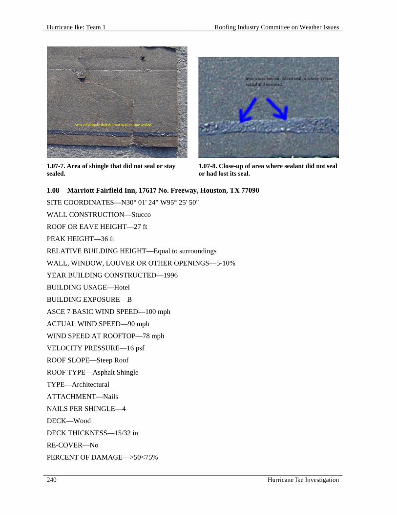
Hurricane Ike: Team 1 Roofing Industry Committee on Weather Issues
240 Hurricane Ike Investigation
1.07-7. Area of shingle that did not seal or stay sealed.
1.07-8. Close-up of area where sealant did not seal or had lost its seal.
1.08 Marriott Fairfield Inn, 17617 No. Freeway, Houston, TX 77090
SITE COORDINATES—N30° 01' 24" W95° 25' 50"
WALL CONSTRUCTION—Stucco
ROOF OR EAVE HEIGHT—27 ft
PEAK HEIGHT—36 ft
RELATIVE BUILDING HEIGHT—Equal to surroundings
WALL, WINDOW, LOUVER OR OTHER OPENINGS—5-10%
YEAR BUILDING CONSTRUCTED—1996
BUILDING USAGE—Hotel
BUILDING EXPOSURE—B
ASCE 7 BASIC WIND SPEED—100 mph
ACTUAL WIND SPEED—90 mph
WIND SPEED AT ROOFTOP—78 mph
VELOCITY PRESSURE—16 psf
ROOF SLOPE—Steep Roof
ROOF TYPE—Asphalt Shingle
TYPE—Architectural
ATTACHMENT—Nails
NAILS PER SHINGLE—4
DECK—Wood
DECK THICKNESS—15/32 in.
RE-COVER—No
PERCENT OF DAMAGE—>50<75%

Roofing Industry Committee on Weather Issues Hurricane Ike: Team 1
Hurricane Ike Investigation 241
DAMAGE INITIATION—Damage began at the eave, followed by other shingles up-slope. Damage was also noted at soffits.
DESCRIBE DAMAGE—50-75% of the roof was damaged - approximately 10-25% at front side, and all of back side.
ROOF DAMAGE APPEARED TO BE CAUSED BY:
1. Improper placement of nails, too high on shingles (high-nailed), primarily just above backer;
2. Shingle sealant once sealed looked like it had released before the storm and precipitated the blow-offs.
MISCELLANEOUS NOTES:
1. Three-story building;
2. Shingle size: 12-1/2 in. x 36 in.;
3. Hotel (Hampton Inn) next door had very little damage.
PHOTOGRAPHS OF ROOF DAMAGE
1.08-1. Site identification. 1.08-2. Overview of facility depicting the water damaged property.
1.08-3. Soffit and edge metal damage. 1.08-4. Nails are placed above the nailing area (high nailed).
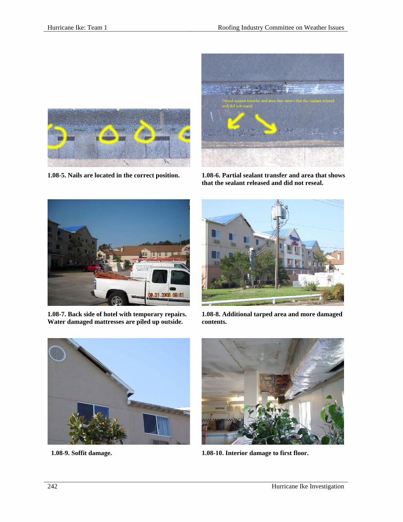
Hurricane Ike: Team 1 Roofing Industry Committee on Weather Issues
242 Hurricane Ike Investigation
1.08-5. Nails are located in the correct position. 1.08-6. Partial sealant transfer and area that shows that the sealant released and did not reseal.
1.08-7. Back side of hotel with temporary repairs. Water damaged mattresses are piled up outside.
1.08-8. Additional tarped area and more damaged contents.
1.08-9. Soffit damage. 1.08-10. Interior damage to first floor.

Roofing Industry Committee on Weather Issues Hurricane Ike: Team 1
Hurricane Ike Investigation 243
1.09 Hampton Inn, 17617 N Freeway, Houston, TX 77384
SITE COORDINATES—N30° 01' 25" W95° 29' 50"
WALL CONSTRUCTION—Stucco
ROOF OR EAVE HEIGHT—28 ft
PEAK HEIGHT—36 ft
RELATIVE BUILDING HEIGHT—Equal to surroundings
WALL, WINDOW, LOUVER OR OTHER OPENINGS—0-5 %
YEAR BUILDING CONSTRUCTED—2000
BUILDING USAGE—Hotel
BUILDING EXPOSURE—B
BUILDING PRESSURIZED—No
ASCE 7 BASIC WIND SPEED—100 mph
ACTUAL WIND SPEED—90 mph
WIND SPEED AT ROOFTOP—78 mph
VELOCITY PRESSURE—16 psf
ROOF SLOPE—Steep Roof
ROOF TYPE—Asphalt Shingle
TYPE—Architectural
ATTACHMENT—Nails
NAILS PER SHINGLE—4
RE-COVER—No
PERCENT OF DAMAGE—>0<10%
DAMAGE INITIATION—Improper installation techniques resulted in poorly attached shingles, leading to damage and blow-off.
DESCRIBE DAMAGE—This three story hotel had little damage, possibly because of wind direction. It was partially sheltered by a large tree line very close to the back of the building. Damage was primarily in the field and some valleys; very little hip and ridge damage.
ROOF DAMAGE APPEARED TO BE CAUSED BY:
1. Lack of adequate seal;
2. Missing nails i.e., no nails located at ends of some shingles;
3. Fasteners located above common bond nail zone.
MISCELLANEOUS NOTES:
1. Shingle was an odd size - 12-5/8 in. x 36-1/4 in.;
2. Wind direction may have been a factor as to why this had very little damage compared to the Fairfield Inn next door, which had greater wind exposure.

Hurricane Ike: Team 1 Roofing Industry Committee on Weather Issues
244 Hurricane Ike Investigation
PHOTOGRAPHS OF ROOF DAMAGE
1.09-1. Site identification. 1.09-2. Overview.
1.09-3. Damaged area. 1.09-4. Shingles show little to no sealant transfer.
1.09-5. Staples were located above fastening area. 1.09-6. Gathering samples.
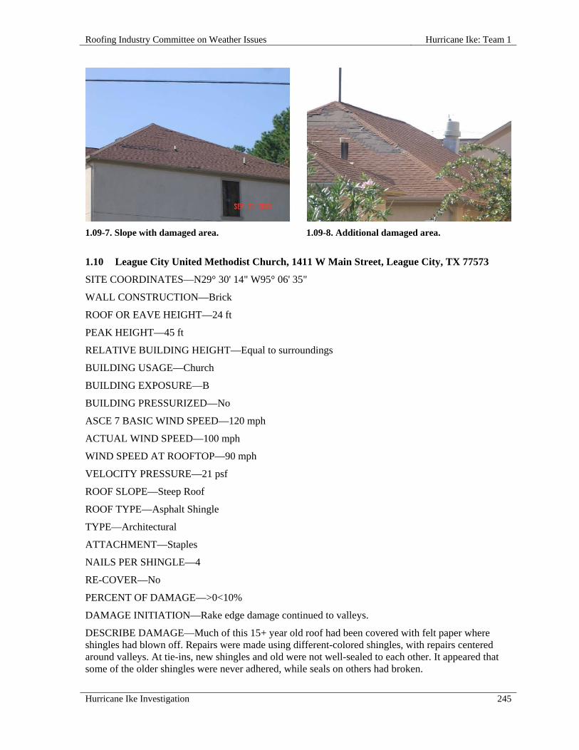
Roofing Industry Committee on Weather Issues Hurricane Ike: Team 1
Hurricane Ike Investigation 245
1.09-7. Slope with damaged area. 1.09-8. Additional damaged area.
1.10 League City United Methodist Church, 1411 W Main Street, League City, TX 77573
SITE COORDINATES—N29° 30' 14" W95° 06' 35"
WALL CONSTRUCTION—Brick
ROOF OR EAVE HEIGHT—24 ft
PEAK HEIGHT—45 ft
RELATIVE BUILDING HEIGHT—Equal to surroundings
BUILDING USAGE—Church
BUILDING EXPOSURE—B
BUILDING PRESSURIZED—No
ASCE 7 BASIC WIND SPEED—120 mph
ACTUAL WIND SPEED—100 mph
WIND SPEED AT ROOFTOP—90 mph
VELOCITY PRESSURE—21 psf
ROOF SLOPE—Steep Roof
ROOF TYPE—Asphalt Shingle
TYPE—Architectural
ATTACHMENT—Staples
NAILS PER SHINGLE—4
RE-COVER—No
PERCENT OF DAMAGE—>0<10%
DAMAGE INITIATION—Rake edge damage continued to valleys.
DESCRIBE DAMAGE—Much of this 15+ year old roof had been covered with felt paper where shingles had blown off. Repairs were made using different-colored shingles, with repairs centered around valleys. At tie-ins, new shingles and old were not well-sealed to each other. It appeared that some of the older shingles were never adhered, while seals on others had broken.

Hurricane Ike: Team 1 Roofing Industry Committee on Weather Issues
246 Hurricane Ike Investigation
One small metal canopy was deflected and there were detached shingles on the main roof. On one side of the chapel the rake edge metal had blown off, but without visible shingle damage.
ROOF DAMAGE APPEARED TO BE CAUSED BY:
1. Valley repair shingles not sealed at tie-in to old roof;
2. Poor shingle sealing and staying sealed;
3. Staples installed high and at angles.
MISCELLANEOUS NOTES:
1. Shingle size: 39-3/8 in. x 13-1/4 in.;
2. Eave at one story and others go up to three stories.
PHOTOGRAPHS OF ROOF DAMAGE
1.10-1. Site Identification. 1.10-2. Overview of church.
1.10-3. Some of the sealant strips did not bond; in other places where it did, the bond was broken; note oxidized sealant.
1.10-4. Some staples were installed too high and at an angle.

Roofing Industry Committee on Weather Issues Hurricane Ike: Team 1
Hurricane Ike Investigation 247
1.10-5. Gutter and edge metal were blown off. Shingles remained intact.
1.10-6. Valley was previously repaired with mismatched shingles.
1.10-7. Shingle with high staple. 1.10-8. View of temporarily repaired area. 1.11 Residence, 1239 Willow Branch Drive, League City, TX 77673
SITE COORDINATES—N29° 29' 53" W95° 05' 33"
WALL CONSTRUCTION—Brick
ROOF OR EAVE HEIGHT—14 ft
PEAK HEIGHT—30 ft
OVERHANG WIDTH—1 ft
RELATIVE BUILDING HEIGHT—Equal to surroundings
BUILDING USAGE—Residence
BUILDING EXPOSURE—B
BUILDING PRESSURIZED—No
ASCE 7 BASIC WIND SPEED—120 mph
ACTUAL WIND SPEED—100 mph
WIND SPEED AT ROOFTOP—85 mph

Hurricane Ike: Team 1 Roofing Industry Committee on Weather Issues
248 Hurricane Ike Investigation
VELOCITY PRESSURE—18 psf
ROOF SLOPE—Steep Roof
ROOF TYPE—Asphalt Shingle
TYPE—Architectural
ATTACHMENT—Nails
NAILS PER SHINGLE—4
DECK—Wood
UNDERLAYMENT—#15 felt
RE-COVER—No
PERCENT OF DAMAGE—>10<25%
DAMAGE INITIATION—Poor fastening practices led to blow-off damage at rake edges.
DESCRIBE DAMAGE—Shingle damage and detachment was noted, mainly in areas near rake edges.
ROOF DAMAGE APPEARED TO BE CAUSED BY:
1. Rake edge shingles not having nails located within 1 in. of shingle ends, allowing wind under them;
2. Full shingles used as starter courses on rake with nails installed over 5 in. from rake edge;
3. Rake edge starter shingles not sealed to roof shingles;
4. Fasteners placed well above the common bond nail zone.
MISCELLANEOUS NOTES:
1. This single-story home had a roof slope that varied from 6:12 and steeper;
2. Shingle size: 13-1/4 in. x 38-1/2 in.;
3. Less than 5% of roofs on this street were damaged.
PHOTOGRAPHS OF ROOF DAMAGE
1.11-1. Site identification. 1.11-2. Oveview of home.

Roofing Industry Committee on Weather Issues Hurricane Ike: Team 1
Hurricane Ike Investigation 249
1.11-3. Team 1 at work. 1.11-4. Undamaged side of roof.
1.11-5. Shingles with nails placed above fastening area.
1.11-6. Nails installed 1-1/2 in. too high.
1.11-7. Incorrect rake edge detail. 1.11-8. Shingles along rake edge did not have nails located at shingle ends. Rake edge starter course nails were placed over 5 in. from rake edge.

Hurricane Ike: Team 1 Roofing Industry Committee on Weather Issues
250 Hurricane Ike Investigation
1.12 Residence, 1231 Willow Branch Drive, League City, TX 77573
SITE COORDINATES—N29° 29' 53" W95° 05' 33"
ROOF OR EAVE HEIGHT—14 ft
PEAK HEIGHT—30 ft
OVERHANG WIDTH—1 ft
RELATIVE BUILDING HEIGHT—Equal to surroundings
YEAR BUILDING CONSTRUCTED—1994
BUILDING USAGE—Residence
BUILDING EXPOSURE—B
ASCE 7 BASIC WIND SPEED—120 mph
ACTUAL WIND SPEED—100 mph
WIND SPEED AT ROOFTOP—85 mph
VELOCITY PRESSURE—18 psf
ROOF SLOPE—Steep Roof
ROOF TYPE—Asphalt Shingle
TYPE—3-tab
ATTACHMENT—Staples
RE-COVER—No
PERCENT OF DAMAGE—>0<10%
DAMAGE INITIATION—Poor fastening methods led to intermittent shingle blow-off damage from eave to ridge.
DESCRIBE DAMAGE—Roof had very little damage. Some shingle damage involved end-tab corners broken off in angled pattern up the roof in nearly a straight line. Starter strips were fabricated using 3-tab shingles installed upside down with tops of shingles positioned at eave edges. Staples were improperly applied.
ROOF DAMAGE APPEARED TO BE CAUSED BY:
1 Wind found weak spots or areas that were not well-sealed;
2 Roof had staples placed high in the sealant and at angles;
3 Starter course not being sealed to first course may have allowed air under shingles to lift up weakly sealed shingles.
MISCELLANEOUS NOTES:
1. Residence was a single story house of various slopes, 8:12 and greater;
2. Wood trim was used as drip edge in places where gutter was not installed.

Roofing Industry Committee on Weather Issues Hurricane Ike: Team 1
Hurricane Ike Investigation 251
PHOTOGRAPHS OF ROOF DAMAGE
1.12-1. Site identification. 1.12-2. Overview.
1.12-3. Damaged area of roof. 1.12-4. Inspector examines damage.
1.12-5. Staples installed in sealant and applied at an angle.
1.12-6. Unsealed starter. Starter shingle was applied with back (sand) side facing up.

Hurricane Ike: Team 1 Roofing Industry Committee on Weather Issues
252 Hurricane Ike Investigation
1.13 Residence, 217 Water Oak Drive, League City, TX 77573
SITE COORDINATES—N29° 29' 55" W95° 05' 36"
ROOF OR EAVE HEIGHT—18 ft
PEAK HEIGHT—28 ft
OVERHANG WIDTH—12 in. - 18 in.
RELATIVE BUILDING HEIGHT—Equal to surroundings
BUILDING USAGE—Residence
BUILDING EXPOSURE—B
ASCE 7 BASIC WIND SPEED—120 mph
ACTUAL WIND SPEED—100 mph
WIND SPEED AT ROOFTOP—84 mph
VELOCITY PRESSURE—18 psf
ROOF SLOPE—Steep Roof
ROOF TYPE—Asphalt Shingle
TYPE—3-tab
ATTACHMENT—Staples
NAILS PER SHINGLE—4
RE-COVER—No
PERCENT OF DAMAGE—>0<10%
DAMAGE INITIATION—Shingles at roof edge blew back and/or off, producing domino effect as more shingles were damaged or lost higher up slope.
DESCRIBE DAMAGE—Roof sustained significant damage. Photo 1.13-3 shows a damage pattern also seen on other roofs, but with no obvious cause. End tabs on each shingle were either completely or partially blown off, in a pattern. One and two story roofs with slopes of 4:12 and steeper exhibited damage above chimney.
ROOF DAMAGE APPEARED TO BE CAUSED BY:
1 Excessive overhang of starter and first course shingles at eaves;
2 Starter course was not sealed to first course;
3 Staples were located too high and were angled.
MISCELLANEOUS NOTES:
1. Over 80% of the houses in this neighborhood had roof damage;
2. Most local houses were built within a year of each other and still had their original 3-tab strip shingle roofs.

Roofing Industry Committee on Weather Issues Hurricane Ike: Team 1
Hurricane Ike Investigation 253
PHOTOGRAPHS OF ROOF DAMAGE
1.13-1. Site identification. 1.13-2. Overall view.
1.13-3. This photo shows a common damage pattern on 3-tab shingles.
1.13-4. Excessive overhang of starter course. First course not sealed.
1.13-5. Corner of roof with damage. 1.13-6. Close up of staple application. Starter course on eave not sealed.

Hurricane Ike: Team 1 Roofing Industry Committee on Weather Issues
254 Hurricane Ike Investigation
1.14 Residence, 1235 Hardwood Drive, League City, TX 77573
SITE COORDINATES—N29° 30' 00" W95° 05' 24"
ROOF OR EAVE HEIGHT—18 ft
PEAK HEIGHT—28 ft
OVERHANG WIDTH—12 in. - 18 in.
RELATIVE BUILDING HEIGHT—Equal to surroundings
BUILDING USAGE—Residence
BUILDING EXPOSURE—B
ASCE 7 BASIC WIND SPEED—120 mph
ACTUAL WIND SPEED—100 mph
WIND SPEED AT ROOFTOP—84 mph
VELOCITY PRESSURE—18 psf
ROOF SLOPE—Steep Roof
ROOF TYPE—Asphalt Shingle
TYPE—3-tab
ATTACHMENT—Staples
NAILS PER SHINGLE—4
DECK—Wood
RE-COVER—No
DAMAGE INITIATION—Shingles at eaves failed due to improper installation (excessive overhang of shingles) affecting both attachment and wind exposure.
DESCRIBE DAMAGE—Some nails were overdriven. Other shingles were fastened with staples installed in a horizontal position, but above the designated fastening area. Shingles extended 1-1/2 in. beyond eaves, and reversed shingles used as starter course resulted in lack of seal. Portions of the roof may have been previously repaired, as one area used nails for fasteners, but most other areas were fastened with staples.
ROOF DAMAGE APPEARED TO BE CAUSED BY:
1. Excessive shingle overhang at eaves;
2. Starter course was not sealed to the first shingle course;
3. Staples may have interfered with sealant bonding;
4. Replacement shingles were not sealed to old shingles at interface.
MISCELLANEOUS NOTES:
1. Hip and ridge shingles performed better than field shingles;
2. Slope on the two levels of this residence was 4:12 or greater.

Roofing Industry Committee on Weather Issues Hurricane Ike: Team 1
Hurricane Ike Investigation 255
PHOTOGRAPHS OF ROOF DAMAGE
1.14-1. Site Identification. 1.14-2. Overall view of house and garage.
1.14-3. No metal drip edge. Starter course not sealed to first course.
1.14-4. Excessive shingle overhang, staple application; first course unsealed.
1.14-5. Staple in sealant, overdriven staples, raised staples.
1.14-6. Field shingles damaged; ridge shingles remained intact.

Hurricane Ike: Team 1 Roofing Industry Committee on Weather Issues
256 Hurricane Ike Investigation
1.15 Residence, 1236 Deer Ridge Drive, League City, TX 77573
SITE COORDINATES—N29° 30' 01" W95° 05' 22"
ROOF OR EAVE HEIGHT—18 ft
PEAK HEIGHT—28 ft
OVERHANG WIDTH—12 in. - 18 in.
RELATIVE BUILDING HEIGHT—Equal to surroundings
YEAR BUILDING CONSTRUCTED—1997
BUILDING USAGE—Residence
BUILDING EXPOSURE—B
ASCE 7 BASIC WIND SPEED—120 mph
ACTUAL WIND SPEED—100 mph
WIND SPEED AT ROOFTOP—84 mph
VELOCITY PRESSURE—18 psf
ROOF SLOPE—Steep Roof
ROOF TYPE—Asphalt Shingle
TYPE—Architectural
ATTACHMENT—Nails
NAILS PER SHINGLE—3
RE-COVER—No
PERCENT OF DAMAGE—>25 <50%
DAMAGE INITIATION—Too few nails and poor fastening patterns contributed to shingle damage and detachment in various areas along the ridge and in the field.
DESCRIBE DAMAGE—Based on placement of tarps used for temporary protection, damage appeared to be most severe around the top, close to the ridge. Blown-off shingles were secured with only three nails per shingle, and no nails within 12 in. of shingle ends.
ROOF DAMAGE APPEARED TO BE CAUSED BY:
1. Improper fastening - three nails per shingle with one end of shingle not fastened; nails placed 2-1/2 in. - 3 in. above the common bond nail zone.
MISCELLANEOUS NOTES:
1. Roof slope varies up to 12:12 on this two story house with shingles applied in December1997;
2. Metric-sized shingles had an exposure of 5-5/8 in.

Roofing Industry Committee on Weather Issues Hurricane Ike: Team 1
Hurricane Ike Investigation 257
PHOTOGRAPHS OF ROOF DAMAGE
1.15-1. Site Identification. 1.15-2. View of southwest corner of house.
1.15-3. View of southeast corner of house. 1.15-4. Closer view of southeast corner.
1.15-5. Nail applied above typical nailing area. 1.15-6. No nails were found within 12 in. of end of shingle.

Hurricane Ike: Team 1 Roofing Industry Committee on Weather Issues
258 Hurricane Ike Investigation
1.15-7. Homeowner's property at curb damaged by
water infiltration.
Roofing Industry Committee on Weather Issues Hurricane Ike: Team 5
Hurricane Ike Investigation 259
HURRICANE IKE: TEAM 5
Overview Team 5 looked at tile and metal roofs. Five low slope roofs and eleven steep slope roofs at fifteen different sites were inspected. All sixteen roofs were on low-rise structures (less than 60 ft high). Twelve of the roofs inspected were on structures located in exposure B; four of the roofs were on structures in exposure C. All of the exposure C roofs were steep slope. Unlike other wind events that RICOWI has investigated, the team did not find a “path of destruction.” Throughout the areas visited, damage was “spotty”—one structure may have significant loss of roofing and/or siding while adjacent, visually similar structures showed little or no damage. This report will not attempt to explain such discrepancies. Rather, it will report what was observed and can be reasonably explained. The structures inspected by Team 5 exhibited damage ranging from blow-off (three roofs) to no observed damage (also three roofs). Of the undamaged roofs one was a low slope, “asphalt and gravel” roof, exposure B, in Friendswood. The building is a single story elementary school constructed in 1970. Based on the appearance of the roof (gravel patina, debris, etc.) the roof is less than 10 years old. The building does not stand out as an unusual design but confirms that a BUR membrane can survive a moderate wind event (peak gust 90 to 100 miles per hour).
Team Members
The following members participated on Team 5:
Steve Heil, data recorder Dave Hunt, report writer, photographer Bobby Whitman, sample collector
Summary Observations
Four of the remaining roofs are discussed below because they typify “good through poor” construction installations that were seen throughout Team 5’s inspections. Inspection 5.09. The Barrington Residence is a new (2008) high-end (multiple million dollar) single family residence on the eastern shore of Trinity Bay, about nine miles south of Anahuac. Based on the Applied Research Associates’ (ARA) wind swath map (Appendix A), this residence may have been subjected to a “Peak Gust Wind Speed” of just over 110 miles per hour. This would make it one of the hardest hit (by wind) during Hurricane Ike, as almost all higher observed peak gusts occurred over water. The roof covering is 24 in. wide, 24 gauge, “snap-lock” architectural standing seam panels. The panel manufacturer could not be determined; however, it is believed that panels are fastened with clips or cleats. The installer paid particular attention to detail (i.e., closing ends of seams, connection at valleys, etc). The roof survived Ike with no apparent damage as a result of the product used and workmanship employed. Inspection 5.02. This is a new, unoccupied engineered metal building at 1305 West Parkwood in Friendswood. At the time of Hurricane Ike the building was “shell erected”— the roof, walls, glazing, etc. were complete but the interior was unfinished and utilities were not installed. Per the

Hurricane Ike: Team 5 Roofing Industry Committee on Weather Issues
260 Hurricane Ike Investigation
ARA wind swath map, this building may have been subjected to “Peak Gust Wind Speed” as high as 90 to 100 miles per hour. (Based on limited damage to trees, utility poles, and other structures in the area, it is suspected that the peak gust was close to 90 miles per hour.) Despite this, three roof panels adjacent to the southeast rake were dislodged from the framing. The gutter and soffit were undamaged; there were no openings in the south wall; there were no parapets or other readily apparent items that might account for the damage. A cursory inspection of the structure could lead to the conclusion that the roof was installed incorrectly (this was the team’s initial reaction). A closer inspection revealed voids in the masonry wall where it terminated under the fascia at the southeast corner of the roof (similar voids were noted at the northeast corner). Since the structure appeared properly designed and there were no apparent errors in the installation of the metal roof, we assumed that the voids allowed rapid pressurization of the underside of the roof at the southeast corner. Coupled with increased wind loading that occurs at corners, the force was sufficient to lift and dislodge the rake trim and panel. The damage at this building shows how the minor lack of attention to detail by a non-roofing contractor can contribute to failure of a well designed and properly installed roof. Inspection 5.07. The San Jacinto Mall in Baytown is a typical large, fully enclosed shopping mall. The mall’s web site states “1.2 million square ft of retail space;” roof surface is estimated at 400,000 sq ft. The mall is a combination of different size and shape boxes on which there are many different roofs at different elevations covered with different materials (e.g., smooth surfaced BUR, gravel surfaced BUR). The area inspected was the roof over a 250 ft long corridor between retail shops. The corridor (roof) was oriented in a southeast to northwest direction. The roof of the corridor is about 14 ft higher than the roofs to its north or south. The area consisted of four 33 ft x 60 ft roofs plus one 33 sq ft roof separated by barrel-arched Plexiglas skylights. Low (1 ft high) parapets extended along both sides of the roof. Its surface was covered with smooth surfaced BUR. The BUR membrane was completely blown off of all five locations; one skylight was destroyed, but all windows along the north and south corridor walls were intact. The inner edge of the parapet cover was secured with exposed through-fasteners at variable spacing (16 in.–32 in. apart). Its outer edge extended down the wall approximately 6 in. and engaged a continuous cleat. The inner edge of the cover was lifted at joints (splice plates) and in corners on the southeast side but it was not dislodged. The greatest observed lifting was at the corners. Based on the location of blown-off membranes and the condition of the parapet cover, it appears that lifting began adjacent at the windward parapet and that it progressed across the roof. Eventually, the membranes separated from the insulation and parapet, became airborne, and landed on a lower roof to the west, 50 ft away. Factors that appear to have contributed to blow-off include:
1. The membrane was mechanically attached with screws and plates at perimeter only—there was no evidence of mechanical fasteners in field of roof;
2. Insulation in field of roof was “spot mopped” to deck—it was not fully adhered; 3. Insulation was installed in “checkerboard” pattern—seams were not staggered.
No significant damage (other than damage caused by wind-blown debris) was noted during inspections of other adjacent roofs. The other roofs were higher and lower; larger and smaller than the damaged area. Included in the other roofs was a much larger gravel surfaced BUR at the southeast end of the corridor. The ages and histories of the blown-off roofs are unknown. Nevertheless, it appears unlikely that an architect, engineer, roof consultant, or manufacturer’s representative participated actively in their design or installation.

Roofing Industry Committee on Weather Issues Hurricane Ike: Team 5
Hurricane Ike Investigation 261
Inspection 5.11. This inspection involved a single story, metal walled building at the southwest corner of the intersection of Maine and Wilcox Streets in Anahuac. The structure, that housed several small businesses, was 100 ft long (north-south) by 75 ft wide. The original roof was a gravel surfaced BUR over a cementitious wood fiber (CWF) panel deck. The roof deck overhung the walls on the north and east elevations by about 4 ft, finished essentially flush with the south wall, and terminated at a low parapet at the west wall. The age of the structure is unknown. At some time after construction, the structure was retro-fitted with a 26 gauge metal roof. Based on the severe deterioration of the CWF panels at the east overhang, it can be assumed that the BUR roof had failed and was leaking. The ridge of the gabled metal roof was orientated north-south; the slope was estimated at 2:12. Ten in. “C” channel rafters, spaced 10 ft apart, were bolted to vertical channels (two bolts per connection) approximately 10 ft apart. Secondary supports, 8 in. “zees” spaced 5 ft apart, were bolted to the rafters (one bolt per connection). There was no evidence of washers (lock or flat) being used at any of the connections. Roof panels were secured to purlins with self-drilling Tek® type fasteners 12 in. apart. For aesthetic effect (to achieve a narrow fascia), rafters along the east elevation were “field modified” by cutting, with a torch, from 10 in. down to 2 in. at the eave end. The underside (soffit) of the overhang was covered with non-perforated metal panels; there was a hung gutter along the eave of the east roof. Failure appears to have occurred when soffit panels on the east elevation lifted (apparently near the center of the structure). The underside of the metal roof was pressurized and upward force lifted and bent the rafters up at the first vertical member to which they were secured. Roof panels continued to lift and then peeled, east to west, by “ripping” purlins from the rafters. The entire roof, with purlins attached, landed 100 ft west of the building. Modes of failure included both purlins pulling over bolt-heads and bolts pulling through rafters. Considering that other structures in the immediate area suffered very minor damage, it must be assumed that severely weakening the rafters by cutting them – FOR AESTHETIC PURPOSES – was the primary cause of failure. It is unknown who authorized, requested, and/or did the cutting but it would be safe to assume the individual(s) did not consider structural factors at the time and probably had limited experience with roofing.
Lessons Learned 1. Hurricanes, at least at lower wind speeds, do not necessarily generate paths or swaths of
destruction – damage may be random and spotty; 2. Minor errors, acts, or omissions by contractors that are not involved with design or
application of the roof can have a profound effect on a properly designed and correctly installed roof assembly;
3. There appears to be a considerable amount of unregulated, or loosely regulated, construction in this part of Texas. Half of the roofs that Team 5 estimated sustained 50 percent or more damage appear to have been installed by handymen, metal workers, unskilled laborers, property owners, or other “non-roofers.” All of the roofs for which damage was estimated at less than 50 percent appear to have been installed by professional roofing contractors;
4. Well designed and properly designed roofs can survive high wind events with little or no damage;
5. If there had been knowledgeable inspection services during the installation, perhaps the conditions observed might have received attention and correction.

Hurricane Ike: Team 5 Roofing Industry Committee on Weather Issues
262 Hurricane Ike Investigation
INDIVIDUAL ROOF REPORTS
5.01 Westwood Elementary, 506 W Edgewood, Friendswood, TX 77546
SITE COORDINATES—N29° 31' 39" W95° 12' 46"
ROOF OR EAVE HEIGHT—16 ft
PEAK HEIGHT—16 ft
BUILDING LENGTH—250 ft
BUILDING WIDTH—60 ft
OVERHANG LENGTH—Perimeter
OVERHANG WIDTH—4 ft
RELATIVE BUILDING HEIGHT—Equal to surroundings
WALL, WINDOW, LOUVER OR OTHER OPENINGS—5-10%
NUMBER OF PENETRATIONS GREATER THAN 4 ft x 4 ft x 2 ft HIGH—2
YEAR BUILDING CONSTRUCTED—1970
BUILDING USAGE—School
BUILDING EXPOSURE—B
BUILDING PRESSURIZED—Yes
ASCE 7 BASIC WIND SPEED—120 mph
ACTUAL WIND SPEED—90 mph
WIND SPEED AT ROOFTOP—70 mph
VELOCITY PRESSURE—13 psf
PRIMARY WIND DIRECTION—All
ROOF SLOPE—Low Slope Roof
ROOF TYPE—Gravel Surfaced BUR
ATTACHED WITH—Fully Adhered - mopped
GRAVEL EMBEDMENT—>75%
PERCENT OF DAMAGE—>0<10%
DAMAGE INITIATION—No damage.
DESCRIBE DAMAGE—No apparent damage to the built-up roof membrane (BUR) except for very minor displacement of gravel.

Roofing Industry Committee on Weather Issues Hurricane Ike: Team 5
Hurricane Ike Investigation 263
PHOTOGRAPHS OF ROOF DAMAGE
5.01-1. South elevation of Westwood showing the southeast corner of the building.
5.01-2. South elevation showing the southwest corner of the building.
5.01-3. View of the roof from the southwest corner. 5.01-4. Another view from the southeast corner of the roof.
5.01-5. View of the field of the roof from the northeast corner shows a wide open graveled BUR.
5.01-6. Most gravel remained in place, although some wind scour was noted.
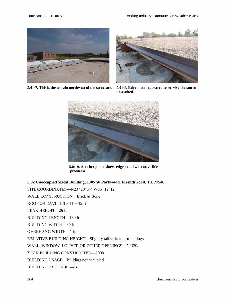
Hurricane Ike: Team 5 Roofing Industry Committee on Weather Issues
264 Hurricane Ike Investigation
5.01-7. This is the terrain northwest of the structure. 5.01-8. Edge metal appeared to survive the storm unscathed.
5.01-9. Another photo shows edge metal with no visible problems.
5.02 Unoccupied Metal Building, 1305 W Parkwood, Friendswood, TX 77546
SITE COORDINATES—N29° 29' 54" W95° 12' 12"
WALL CONSTRUCTION—Brick & stone
ROOF OR EAVE HEIGHT—12 ft
PEAK HEIGHT—26 ft
BUILDING LENGTH—180 ft
BUILDING WIDTH—80 ft
OVERHANG WIDTH—1 ft
RELATIVE BUILDING HEIGHT—Slightly taller than surroundings
WALL, WINDOW, LOUVER OR OTHER OPENINGS—5-10%
YEAR BUILDING CONSTRUCTED—2008
BUILDING USAGE—Building not occupied
BUILDING EXPOSURE—B

Roofing Industry Committee on Weather Issues Hurricane Ike: Team 5
Hurricane Ike Investigation 265
BUILDING PRESSURIZED—No
ASCE 7 BASIC WIND SPEED—120 mph
ACTUAL WIND SPEED—90 mph
WIND SPEED AT ROOFTOP—75 mph
VELOCITY PRESSURE—14 psf
PRIMARY WIND DIRECTION—Cornering wind
ROOF SLOPE—Steep Roof
ROOF TYPE—Metal Architectural Standing Seam
SECONDARY SUPPORT TYPE—Zee purlins
SECONDARY SUPPORT SPACING—4 ft 6 in. o.c.
DECK—Metal
INSULATION TYPE—Batt insulation below deck
INSULATION THICKNESS—3/4 in.
ATTACHMENT—Standing Seam Clips
SURFACE—Metal Color tan
METAL—Galvalume
METAL THICKNESS—24 gauge
PANEL WIDTH—16 in.
RE-COVER—No
PERCENT OF DAMAGE—>0<10%
DAMAGE INITIATION—Rake panels separated from boot clips.
DESCRIBE DAMAGE—Most damage was confined to three panels along the southeast rake edge. A Panel adjacent to the rake, and rake-to-fascia trim dislodged to within approximately 5 ft of the ridge and extended over the end-wall. Two panels adjacent to the rake panel had "lifted." The first and third seams from the rake had disengaged. A second seam appeared to be still engaged, although lifted from purlins.
Eave fasteners were dislodged from the rake panel, and some fastener pull-through was noted in a panel at the eave.
ROOF DAMAGE APPEARED TO BE CAUSED BY:
1. Rapid pressurization of the structure due to voids at tops of masonry end-walls at the southeast and northeast corners;
2. SSR clips disengaged from panel seams.

Hurricane Ike: Team 5 Roofing Industry Committee on Weather Issues
266 Hurricane Ike Investigation
MISCELLANEOUS NOTES:
1. This is a new, as of yet unoccupied metal building; except for the installation of one door, the shell was complete; day crews were installing utility connections (water, electric, etc.) at time of inspection;
2. The 24 gauge, architectural standing seam metal roof appeared to be properly designed and correctly installed;
3. Roof panels were full eave-to-ridge length with no end joints or transverse seams.
PHOTOGRAPHS OF ROOF DAMAGE
5.02-1. View of the southeast corner. 5.02-2. View of the southwest corner.
5.02-3. A closer look of the southeast corner clearly shows panel damage along the rake edge.
5.02-4. Fastener (screw) "pull-through" holes can be seen in this panel near its eave end.

Roofing Industry Committee on Weather Issues Hurricane Ike: Team 5
Hurricane Ike Investigation 267
5.02-5. Eave construction at the southeast corner.
5.02-6. Cleats were installed along the rake.
5.02-7. Rake construction and an opened seam are visible.
5.02-8. View of the ridge at the eastern rake.
5.02-9. At the southeast corner, note the rake trim/wall juncture, and voids in the masonry wall.
5.02-10. At the northeast corner, note masonry voids at juncture with rake.
5.03 Robert's Carpet, 20810 Gulf Freeway, Webster, TX 77598
SITE COORDINATES—N29° 31' 24" W95° 7' 50"
WALL CONSTRUCTION—Block
ROOF OR EAVE HEIGHT—19 ft

Hurricane Ike: Team 5 Roofing Industry Committee on Weather Issues
268 Hurricane Ike Investigation
PEAK HEIGHT—23 ft
PARAPET HEIGHT—32 ft
BUILDING LENGTH—390 ft
BUILDING WIDTH—330 ft
RELATIVE BUILDING HEIGHT—Equal to surroundings
WALL, WINDOW, LOUVER OR OTHER OPENINGS—10-20%
NUMBER OF PENETRATIONS GREATER THAN 4 ft x 4 ft x 2 ft HIGH—23
BUILDING USAGE—Showroom / warehouse
BUILDING EXPOSURE—C
BUILDING PRESSURIZED—Yes
ASCE 7 BASIC WIND SPEED—120 mph
ACTUAL WIND SPEED—100 mph
WIND SPEED AT ROOFTOP—98 mph
VELOCITY PRESSURE—25 psf
PRIMARY WIND DIRECTION—Perpendicular to long side
ROOF SLOPE—Low Slope Roof
ROOF TYPE—Fully Adhered Single Ply
DECK—Metal
PUNCTURES #—>100
TEARS #—Numerous
INSULATION TYPE—Polyisocyanurate Foam
INSULATION THICKNESS—1-1/2 in.
INSULATION ATTACHMENT—Screws & plates
MEMBRANE—EPDM
MEMBRANE ATTACHED TO—Insulation
ATTACHED WITH—Fleece backed - mopped
SURFACE—White
PERCENT OF DAMAGE—>25 <50%
DAMAGE INITIATION—Perimeter edge nailers and metal failed.
DESCRIBE DAMAGE—Edge metal was damaged and/or detached. The single ply membrane was ripped, torn and punctured. Additional damage (punctures beyond area of peeled membrane) were caused by wind-blown debris e.g., HVAC metal doors, edge metal, nailer, etc.
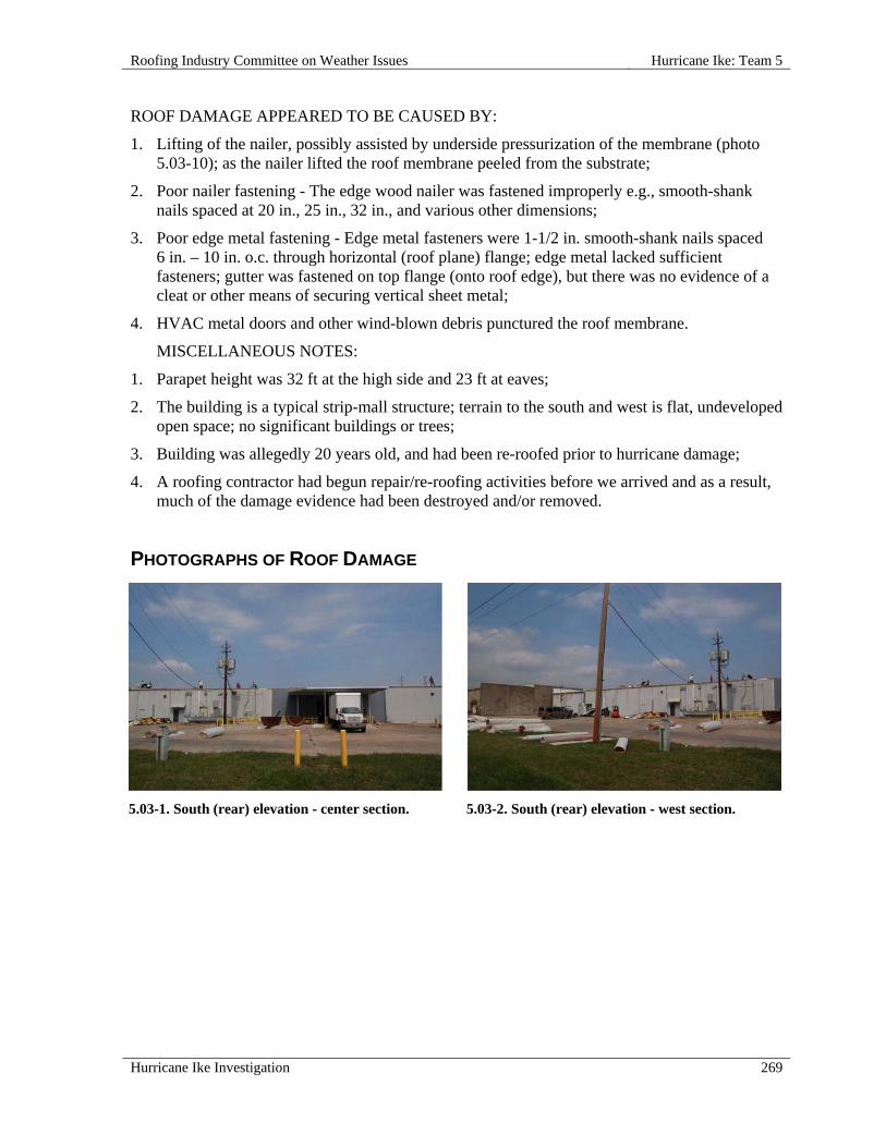
Roofing Industry Committee on Weather Issues Hurricane Ike: Team 5
Hurricane Ike Investigation 269
ROOF DAMAGE APPEARED TO BE CAUSED BY:
1. Lifting of the nailer, possibly assisted by underside pressurization of the membrane (photo 5.03-10); as the nailer lifted the roof membrane peeled from the substrate;
2. Poor nailer fastening - The edge wood nailer was fastened improperly e.g., smooth-shank nails spaced at 20 in., 25 in., 32 in., and various other dimensions;
3. Poor edge metal fastening - Edge metal fasteners were 1-1/2 in. smooth-shank nails spaced 6 in. – 10 in. o.c. through horizontal (roof plane) flange; edge metal lacked sufficient fasteners; gutter was fastened on top flange (onto roof edge), but there was no evidence of a cleat or other means of securing vertical sheet metal;
4. HVAC metal doors and other wind-blown debris punctured the roof membrane.
MISCELLANEOUS NOTES:
1. Parapet height was 32 ft at the high side and 23 ft at eaves;
2. The building is a typical strip-mall structure; terrain to the south and west is flat, undeveloped open space; no significant buildings or trees;
3. Building was allegedly 20 years old, and had been re-roofed prior to hurricane damage;
4. A roofing contractor had begun repair/re-roofing activities before we arrived and as a result, much of the damage evidence had been destroyed and/or removed.
PHOTOGRAPHS OF ROOF DAMAGE
5.03-1. South (rear) elevation - center section. 5.03-2. South (rear) elevation - west section.
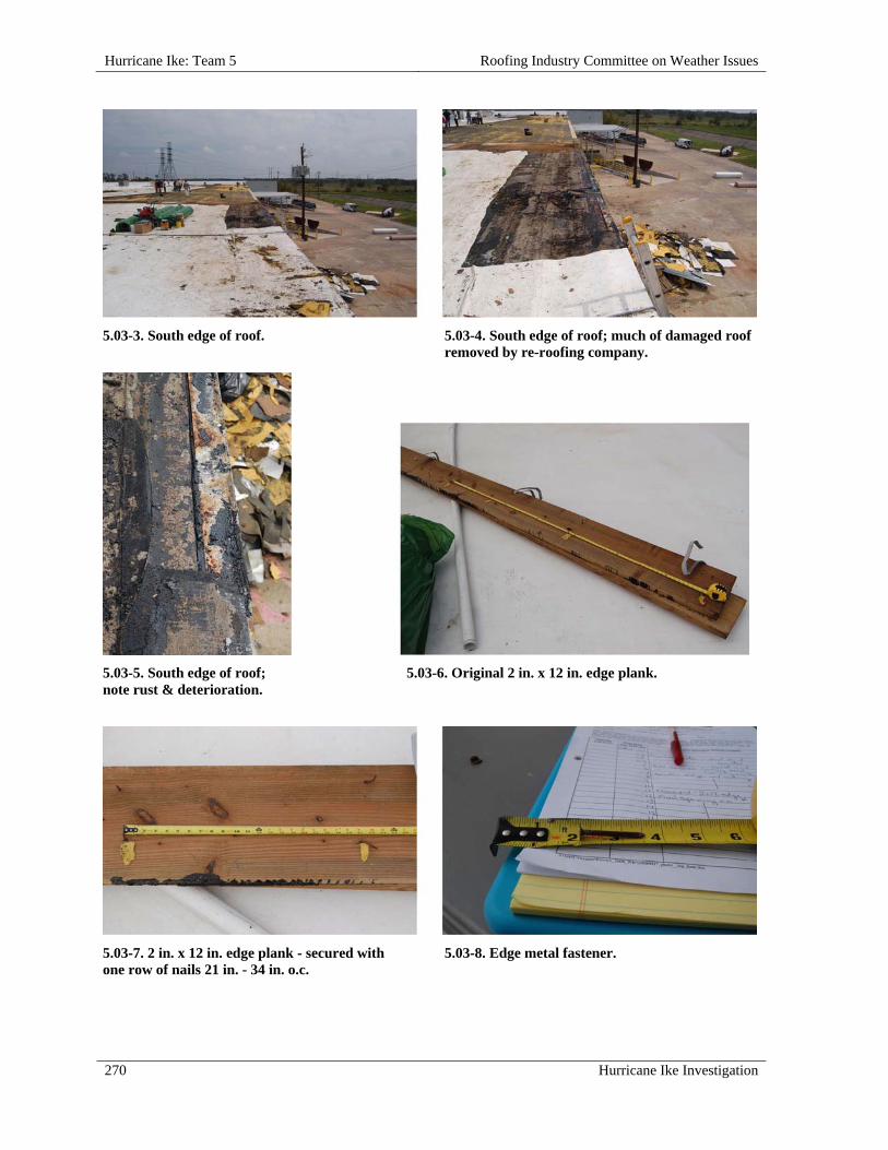
Hurricane Ike: Team 5 Roofing Industry Committee on Weather Issues
270 Hurricane Ike Investigation
5.03-3. South edge of roof.
5.03-4. South edge of roof; much of damaged roof removed by re-roofing company.
5.03-5. South edge of roof; note rust & deterioration.
5.03-6. Original 2 in. x 12 in. edge plank.
5.03-7. 2 in. x 12 in. edge plank - secured with one row of nails 21 in. - 34 in. o.c.
5.03-8. Edge metal fastener.

Roofing Industry Committee on Weather Issues Hurricane Ike: Team 5
Hurricane Ike Investigation 271
5.03-9. Top of south wall believed to be near location of first lifting.
5.03-10. Detail of photo 5.03-9.
5.04 TEI Staffing, 2525 Highway 6, Alvin, TX 77511
SITE COORDINATES—N29° 25' 15" W95° 13' 16"
WALL CONSTRUCTION—Brick
ROOF OR EAVE HEIGHT—12 ft
PEAK HEIGHT—13 ft
BUILDING LENGTH—70 ft
BUILDING WIDTH—60 ft
RELATIVE BUILDING HEIGHT—Slightly taller than surroundings
WALL, WINDOW, LOUVER OR OTHER OPENINGS—5-10%
BUILDING USAGE—Commercial office
BUILDING EXPOSURE—B
BUILDING PRESSURIZED—Yes
ASCE 7 BASIC WIND SPEED—120 mph
ACTUAL WIND SPEED—90 mph
WIND SPEED AT ROOFTOP—68 mph
VELOCITY PRESSURE—12 psf
PRIMARY WIND DIRECTION—Cornering wind
ROOF SLOPE—Low Slope Roof
ROOF TYPE—Modified Bitumen
DECK—Metal
TEARS #—Major
INSULATION ATTACHMENT—Not attached
MEMBRANE ATTACHED TO—Lightweight Insulating Concrete
ATTACHED WITH—Split-shank fasteners

Hurricane Ike: Team 5 Roofing Industry Committee on Weather Issues
272 Hurricane Ike Investigation
SURFACE—Granules
PERCENT OF DAMAGE—100%
DAMAGE INITIATION—Edge metal failed at corners, starting at the southwest corner, and allowed the membrane to peel off.
DESCRIBE DAMAGE—Approximately 80% of the field membrane was detached from the roof and edge metal tore off at roof corners.
ROOF DAMAGE APPEARED TO BE CAUSED BY:
1. Inadequate fastening at perimeter edges -Edge metal was fastened with smooth-shank nails spaced 10 in. - 14 in. o.c., and the cap sheet was not adequately stripped-in at edges;
2. Poor fastening of base sheet to lightweight insulating concrete (LWIC) deck; fastener spacing was measured at 32 in. o.c. in the field; some fasteners were rusted and then broke off at deck level; some base sheet fasteners didn't appear to fully engage the LWIC;
3. Poor bond between base ply and cap sheets.
MISCELLANEOUS NOTES:
1. This was a single story structure with a low slope roof;
2. Age of building and roof assembly were unknown but condition of roofing substrates and other items suggest the damaged roof was not the original assembly.
PHOTOGRAPHS OF ROOF DAMAGE
5.04-1. A ground view of the southwest corner. 5.04-2. View of the roof is from the southwest corner; note damage at far right.
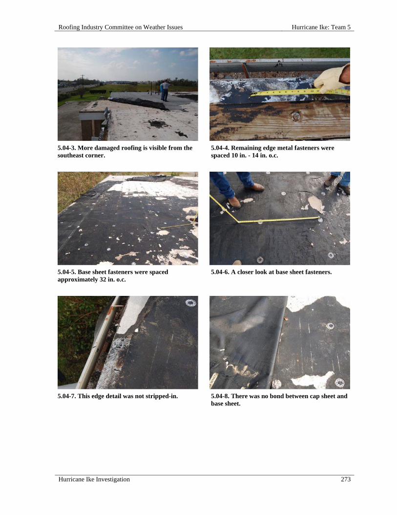
Roofing Industry Committee on Weather Issues Hurricane Ike: Team 5
Hurricane Ike Investigation 273
5.04-3. More damaged roofing is visible from the southeast corner.
5.04-4. Remaining edge metal fasteners were spaced 10 in. - 14 in. o.c.
5.04-5. Base sheet fasteners were spaced approximately 32 in. o.c.
5.04-6. A closer look at base sheet fasteners.
5.04-7. This edge detail was not stripped-in. 5.04-8. There was no bond between cap sheet and
base sheet.
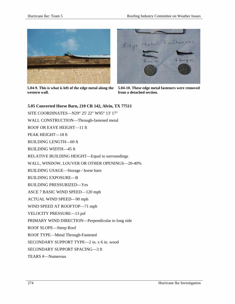
Hurricane Ike: Team 5 Roofing Industry Committee on Weather Issues
274 Hurricane Ike Investigation
5.04-9. This is what is left of the edge metal along the western wall.
5.04-10. These edge metal fasteners were removed from a detached section.
5.05 Converted Horse Barn, 210 CR 142, Alvin, TX 77511
SITE COORDINATES—N29° 25' 22" W95° 13' 17"
WALL CONSTRUCTION—Through-fastened metal
ROOF OR EAVE HEIGHT—11 ft
PEAK HEIGHT—18 ft
BUILDING LENGTH—60 ft
BUILDING WIDTH—45 ft
RELATIVE BUILDING HEIGHT—Equal to surroundings
WALL, WINDOW, LOUVER OR OTHER OPENINGS—20-40%
BUILDING USAGE—Storage / horse barn
BUILDING EXPOSURE—B
BUILDING PRESSURIZED—Yes
ASCE 7 BASIC WIND SPEED—120 mph
ACTUAL WIND SPEED—90 mph
WIND SPEED AT ROOFTOP—71 mph
VELOCITY PRESSURE—13 psf
PRIMARY WIND DIRECTION—Perpendicular to long side
ROOF SLOPE—Steep Roof
ROOF TYPE—Metal Through-Fastened
SECONDARY SUPPORT TYPE—2 in. x 6 in. wood
SECONDARY SUPPORT SPACING—3 ft
TEARS #—Numerous

Roofing Industry Committee on Weather Issues Hurricane Ike: Team 5
Hurricane Ike Investigation 275
SURFACE—White
METAL—Galvalume
METAL THICKNESS—29 gauge
PANEL WIDTH—36 in.
FASTENER ROW SPACING—3 per panel
RE-COVER—No
PERCENT OF DAMAGE—>50<75%
DAMAGE INITIATION—Damage started at southeast corner eaves, leading to blow-off of roof panels.
DESCRIBE DAMAGE—Damaged and or detached roof panels were noted at rake and eave locations. Roof lights were blown out in three locations. Secondary 2 in. x 6 in. joists were dislodged in two bays.
ROOF DAMAGE APPEARED TO BE CAUSED BY:
1. Pressurization of building through eave/wall juncture; as is typical with pole-barn construction, roof panels overhang walls with no enclosed fascia/soffit; pressurization due to open eaves and/or blow-off of wall panels over doors, which resulted in blow-out of three roof panels and/or skylights and peeling of roof at southeast corner;
2. Poor securement of purlins to rafters and of metal roofing to purlins; joist hangers were attached using only one screw on some joists; panel-to-joist fasteners were only 1 in. long and were rusted;
3. Fasteners pulled through panels and pulled out of joists.
MISCELLANEOUS NOTES:
1. This building was a wood framed metal “pole barn” that had been converted from a horse barn to a storage facility.
PHOTOGRAPHS OF ROOF DAMAGE
5.05-1. South elevation; note damage at right end. 5.05-2. A roof joist with purlin hangers is visible
in the area of loss.

Hurricane Ike: Team 5 Roofing Industry Committee on Weather Issues
276 Hurricane Ike Investigation
5.05-3. Interior view of roof damage.
5.05-4. Joists and purlin hangers are clearly seen from the interior.
5.05-5. An example of fastener pull-out is visible at the end of this detached purlin.
5.05-6. Note fastener spacing in this roof panel.
5.05-7. Typical metal panel fasteners.

Roofing Industry Committee on Weather Issues Hurricane Ike: Team 5
Hurricane Ike Investigation 277
5.06 Carino's Italian Restaurant, 5921 Beltway 8 E, Houston, TX 77048
SITE COORDINATES—N29° 48' 40" W95° 9' 53"
WALL CONSTRUCTION—Stucco & stone
ROOF OR EAVE HEIGHT—12 ft
PEAK HEIGHT—22 ft
BUILDING LENGTH—70 ft
BUILDING WIDTH—60 ft
OVERHANG LENGTH—Perimeter
OVERHANG WIDTH—18 in.
RELATIVE BUILDING HEIGHT—Equal to surroundings
WALL, WINDOW, LOUVER OR OTHER OPENINGS—20-40%
YEAR BUILDING CONSTRUCTED—2000
BUILDING USAGE—Restaurant
BUILDING EXPOSURE—B
BUILDING PRESSURIZED—Yes
ASCE 7 BASIC WIND SPEED—120 mph
ACTUAL WIND SPEED—90 mph
WIND SPEED AT ROOFTOP—73 mph
VELOCITY PRESSURE—14 psf
PRIMARY WIND DIRECTION—All
ROOF SLOPE—Steep Roof
ROOF TYPE—Concrete or Clay Tile
ATTACHMENT—Nailed
TILE SHAPE—Barrel Tile
TILE LENGTH—19 in.
TILE WIDTH—14 in.
FASTENERS PER TILE—1
DECK—Wood
DECK THICKNESS—1/2 in.
UNDERLAYMENT—Solid adhered ice and water shield
RE-COVER—No
PERCENT OF DAMAGE—>0<10%
DAMAGE INITIATION—Perimeter edge failures led to damaged, displaced, and detached tile.

Hurricane Ike: Team 5 Roofing Industry Committee on Weather Issues
278 Hurricane Ike Investigation
DESCRIBE DAMAGE—Most damage was at perimeter edges, although some field damage was noted.
Minor, spotty damage was observed on all roof planes (north, south, and east elevations). Damage consisted of tiles that were blown off, tiles that were loosened and twisted but remained on roof, and broken tiles. Damage occurred on rakes, at eaves, and in the field, with no apparent pattern. Hurricane (or storm) clips were not installed on butt ends of tiles.
ROOF DAMAGE APPEARED TO BE CAUSED BY:
1. An insufficient amount of hurricane clips at perimeter areas made these tiles susceptible to blow-off and displacement.
MISCELLANEOUS NOTES:
1. Carino’s Italian Restaurant was located in a strip mall complex;
2. Clay tile was installed on steep-slope “shed” roofs; upper ends were well-terminated at mechanical equipment level on north and east elevations; tower had a hip roof and the south elevation had a gable roof;
3. This Carino’s restaurant may be a “boilerplate design” common to all locations, which may explain why no hurricane clips were used i.e., most locations have no need for them.
PHOTOGRAPHS OF ROOF DAMAGE
5.06-1. View of the southeast corner.
5.06-2. West elevation shows a closer view of the tile roof.

Roofing Industry Committee on Weather Issues Hurricane Ike: Team 5
Hurricane Ike Investigation 279
5.06-3. Note damage along the rake on the west elevation.
5.06-4. East elevation also exhibits damaged tile.
5.06-5. A close-up view of the eave on the eastern edge of the main roof.
5.06-6. Note the displaced tiles along this northern rake.
5.06-7. This is the eastern eave of the tower.

Hurricane Ike: Team 5 Roofing Industry Committee on Weather Issues
280 Hurricane Ike Investigation
5.07 San Jacinto Mall, 1000 San Jacinto Mall, Baytown, TX 77521
SITE COORDINATES—N29° 47' 59" W94° 58' 58"
WALL CONSTRUCTION—Stucco & brick
ROOF OR EAVE HEIGHT—37 ft
PEAK HEIGHT—38 ft
BUILDING LENGTH—60 ft
BUILDING WIDTH—33 ft
RELATIVE BUILDING HEIGHT—Equal to surroundings
WALL, WINDOW, LOUVER OR OTHER OPENINGS—0-5 %
NUMBER OF PENETRATIONS GREATER THAN 4 ft x 4 ft x 2 ft HIGH—1
YEAR BUILDING CONSTRUCTED—1970
BUILDING USAGE—Mall / retail
BUILDING EXPOSURE—B
BUILDING PRESSURIZED—Yes
ASCE 7 BASIC WIND SPEED—120 mph
ACTUAL WIND SPEED—110 mph
WIND SPEED AT ROOFTOP—97 mph
VELOCITY PRESSURE—24 psf
PRIMARY WIND DIRECTION—Perpendicular to long side
ROOF SLOPE—Low Slope Roof
ROOF TYPE—Smooth Surfaced BUR
DECK—Metal
INSULATION TYPE—Fiberglass Board
INSULATION THICKNESS—2 in.
INSULATION ATTACHMENT—Screws & plates
MEMBRANE ATTACHED TO—Insulation
ATTACHED WITH—Strip-mopped
SURFACE—Aluminum coating
PERCENT OF DAMAGE—100%
DAMAGE INITIATION—Roof membrane detached from insulation and was blown off the roof. Based on location of blown off membranes, it appears lifting began adjacent to windward parapets and progressed across the roof.

Roofing Industry Committee on Weather Issues Hurricane Ike: Team 5
Hurricane Ike Investigation 281
DESCRIBE DAMAGE—The built-up roof membrane (BUR) was completely detached from all three roof areas. Eventually, the membrane pulled away from perimeter edges, separated from insulation, became airborne, and landed on a lower roof 50 ft away. The metal edge pulled away from the walls, but remained attached.
On parapets, inner edges of metal coping were secured with exposed fasteners at inconsistent spacing e.g., 16 in. – 32 in. o.c. Inner edges of coping were lifted in various areas on the apparent windward (southeast) side, but remained in place. The greatest lifting observed was at the corners. Barrel-type skylights were also damaged.
Other than minor damage from wind-blown debris, no significant damage was noted on other roofs, including higher, lower, larger, and smaller roofs.
ROOF DAMAGE APPEARED TO BE CAUSED BY:
1. Membrane Attachment - BUR was securely fastened (with screws and plates) only at the perimeter; there was no evidence of mechanical fasteners in the field of the roof; the system relied only on spot-mopped asphalt adhesive;
2. Insulation Attachment - Insulation boards in the field were only spot mopped to the deck, not fully adhered; insulation seams were not staggered, which can affect cohesive strength of the insulation system;
3. Metal Edge Attachment - Metal edge was nailed at inconsistent spacing e.g., 24 in., 16 in., 32 in. o.c.
MISCELLANEOUS NOTES:
1. The San Jacinto Mall is a multi-story, fully enclosed shopping mall with 1.2 million sq ft of retail space; total roof area is estimated be 400,000 sq ft;
2. The mall appears to be a combination of “boxes” of different sizes and shapes that were added over time; this resulted in many different roofs at different elevations, and surfaced with different materials e.g., smooth surfaced BUR, gravel surfaced BUR, etc.;
3. Two identical sites in the mall were investigated; the two areas consisted of 33 ft x 60 ft roofs; long axes of the roofs were southeast to northwest; low parapets (approximately 12 in. high) were on the long sides; barrel-arched Plexiglas skylights separated the two roofs; the failure modes of the two roofs were similar;
4. Also inspected was one 33 ft x 32 ft smooth surfaced BUR roof.

Hurricane Ike: Team 5 Roofing Industry Committee on Weather Issues
282 Hurricane Ike Investigation
PHOTOGRAPHS OF ROOF DAMAGE
5.07-1. A partial south elevation shows damaged upper roofs from a lower level.
5.07-2. A lower, undamaged roof and terrain south of a damaged roof.
5.07-3. View of damaged roof #2 from the northwest corner.
5.07-4. This is the same roof from the northeast corner.
5.07-5. Widespread blow-off damage occurred to roof #3 (from northwest corner).
5.07-6. This is damaged roof #3 from the southwest corner. Roof #2 is in the background.

Roofing Industry Committee on Weather Issues Hurricane Ike: Team 5
Hurricane Ike Investigation 283
5.07-7. Fasteners in the first row of insulation panels are visible on the east side of roof #3.
5.07-8. A closer view of the same fasteners, with a tape measure.
5.07-9. Spot mopped insulation provided too little adhesion to prevent blow-off.
5.07-10. Damage on roof #3 (southeast to northwest view).
5.08 Sloan Residence, 203 N Ross Sterling, Anahuac, TX 77514
SITE COORDINATES—N29° 46' 33" W94° 40' 12"
WALL CONSTRUCTION—Metal panel
ROOF OR EAVE HEIGHT—15 ft
PEAK HEIGHT—20 ft
BUILDING LENGTH—80 ft
BUILDING WIDTH—60 ft
OVERHANG LENGTH—Perimeter
OVERHANG WIDTH—2 ft
RELATIVE BUILDING HEIGHT—Equal to surroundings
WALL, WINDOW, LOUVER OR OTHER OPENINGS—20-40%
YEAR BUILDING CONSTRUCTED—2007
BUILDING USAGE—Garage storage
BUILDING EXPOSURE—B

Hurricane Ike: Team 5 Roofing Industry Committee on Weather Issues
284 Hurricane Ike Investigation
BUILDING PRESSURIZED—No
ASCE 7 BASIC WIND SPEED—120 mph
ACTUAL WIND SPEED—110 mph
WIND SPEED AT ROOFTOP—88 mph
VELOCITY PRESSURE—20 psf
PRIMARY WIND DIRECTION—Perpendicular to long side
ROOF SLOPE—Steep Roof
ROOF TYPE—Metal Through-Fastened
SECONDARY SUPPORT TYPE—Zee steel purlins
SECONDARY SUPPORT SPACING—60 in.
INSULATION TYPE—None
ATTACHMENT—Through-fastened
METAL—Galvanized
METAL THICKNESS—26 gauge
PANEL WIDTH—36 in.
RE-COVER—No
PERCENT OF DAMAGE—>50<75%
DAMAGE INITIATION—Failure of garage doors led to blow-off of roof system and back wall.
DESCRIBE DAMAGE—The overhead doors were blown in and roof system components were detached, 90 ft away. The back wall was also detached and was found 50 ft away.
ROOF DAMAGE APPEARED TO BE CAUSED BY:
1. Door Failure - Failure appears to have occurred when the lightweight garage doors blew in, pressurizing the interior; this apparently caused the metal roof and back wall to blow off;
2. Structural Flaws – It appeared that zee purlins were not correctly sized for bays and that connectors were not bolted.
MISCELLANEOUS NOTES:
1. An estimated 90% of fasteners pulled through the panels, and approximately 10% pulled out of purlins;
2. This is a two story metal building with a single family residence on the second floor and a business office and garage / workshop at ground level; original structure was 60 ft x 60 ft with a 20 ft x 60 ft addition attached to the east end; building appears to have been designed and built by the owner;
3. The roof is a straight gable with ridge oriented on an east / west axis;
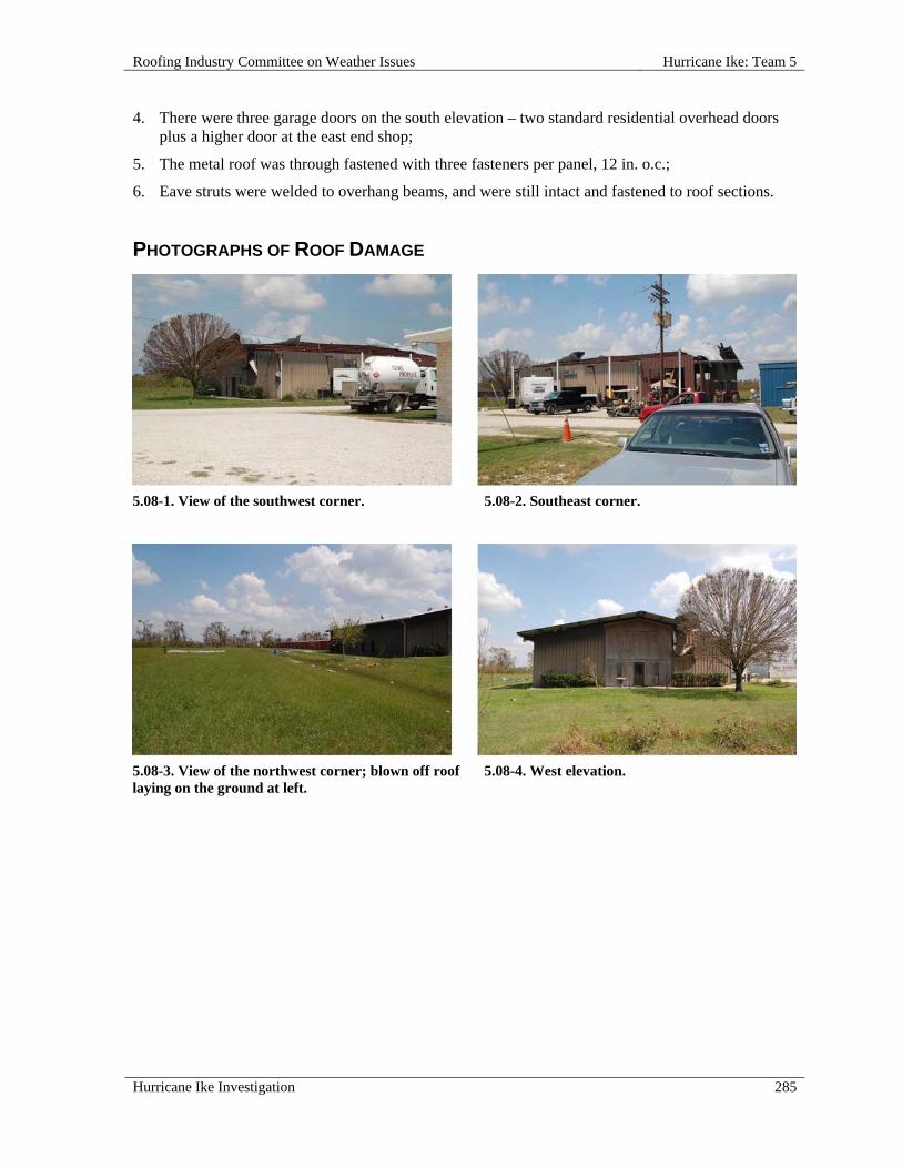
Roofing Industry Committee on Weather Issues Hurricane Ike: Team 5
Hurricane Ike Investigation 285
4. There were three garage doors on the south elevation – two standard residential overhead doors plus a higher door at the east end shop;
5. The metal roof was through fastened with three fasteners per panel, 12 in. o.c.;
6. Eave struts were welded to overhang beams, and were still intact and fastened to roof sections.
PHOTOGRAPHS OF ROOF DAMAGE
5.08-1. View of the southwest corner.
5.08-2. Southeast corner.
5.08-3. View of the northwest corner; blown off roof laying on the ground at left.
5.08-4. West elevation.

Hurricane Ike: Team 5 Roofing Industry Committee on Weather Issues
286 Hurricane Ike Investigation
5.08-5. Southwest corner detail.
5.08-6. The rear of building (northeast corner) shows a blown out section.
5.08-7. Fastener "pull-out" holes are visible in this section of blown off roof.
5.08-8. The welded connection of north (rear) eave purlin to rafter.
5.08-9. A broken weld at the connection of eave purlin-to-rafter on the south (front) elevation.
5.08-10. Blown out garage doors now lie in a "scrap pile."

Roofing Industry Committee on Weather Issues Hurricane Ike: Team 5
Hurricane Ike Investigation 287
5.09 Barrington Residence, 2201 W Bayshore, Anahuac, TX 77514
SITE COORDINATES—N29° 40' 57" W94° 41' 38"
WALL CONSTRUCTION—Stucco over concrete
ROOF OR EAVE HEIGHT—12 ft
PEAK HEIGHT—30 ft
BUILDING LENGTH—150 ft
BUILDING WIDTH—50 ft
OVERHANG LENGTH—Perimeter
OVERHANG WIDTH—1 ft
RELATIVE BUILDING HEIGHT—Slightly taller than surroundings
WALL, WINDOW, LOUVER OR OTHER OPENINGS—10-20%
YEAR BUILDING CONSTRUCTED—2008
BUILDING CODE AT TIME OF CONSTRUCTION—IBC
BUILDING USAGE—Residence
BUILDING EXPOSURE—C
BUILDING PRESSURIZED—Yes
ASCE 7 BASIC WIND SPEED—120 mph
ACTUAL WIND SPEED—110 mph
WIND SPEED AT ROOFTOP—111 mph
VELOCITY PRESSURE—32 psf
PRIMARY WIND DIRECTION—All
ROOF SLOPE—Steep Roof
ROOF TYPE—Metal Architectural Standing Seam
SECONDARY SUPPORT TYPE—Fastened to deck
DECK—Wood
INSULATION TYPE—Spray Polyurethane
ATTACHMENT—Standing Seam Clips
SURFACE—Metal Color
METAL—Galvalume
METAL THICKNESS—24 gauge
PANEL WIDTH—24 in.
RE-COVER—No
DAMAGE INITIATION—No damage.

Hurricane Ike: Team 5 Roofing Industry Committee on Weather Issues
288 Hurricane Ike Investigation
DESCRIBE DAMAGE—Despite considerable damage to nearby buildings, trees, etc., no damage was observed on this roof.
MISCELLANEOUS NOTES:
1. This residence, built in 2008, is a very well constructed single family home on the east side of Trinity Bay north of Oak Island;
2. The structure is situated atop a man-made hill (as opposed to stilts);
3. The line of storm debris indicates that the surge reached to within 3 or 4 ft of this structure;
4. Based on Applied Research Associates’ (ARA) wind swath map, residence may have been subjected to the highest observed “Peak Gust Wind Speed” of 110+ mph;
5. The roof covering consists of 24 in. wide, 24-gauge, snap-lock architectural standing seam panels;
6. It appears that panels are fastened with clips or cleats;
7. Observed attention to detail e.g., closing ends of seams, indicates good workmanship.
PHOTOGRAPHS OF ROOF DAMAGE
5.09-1. View from the northeast. 5.09-2. View of northwest corner.
5.09-3. In this view at the southwest corner, note debris from high water in front.
5.09-4. View of southeast corner.
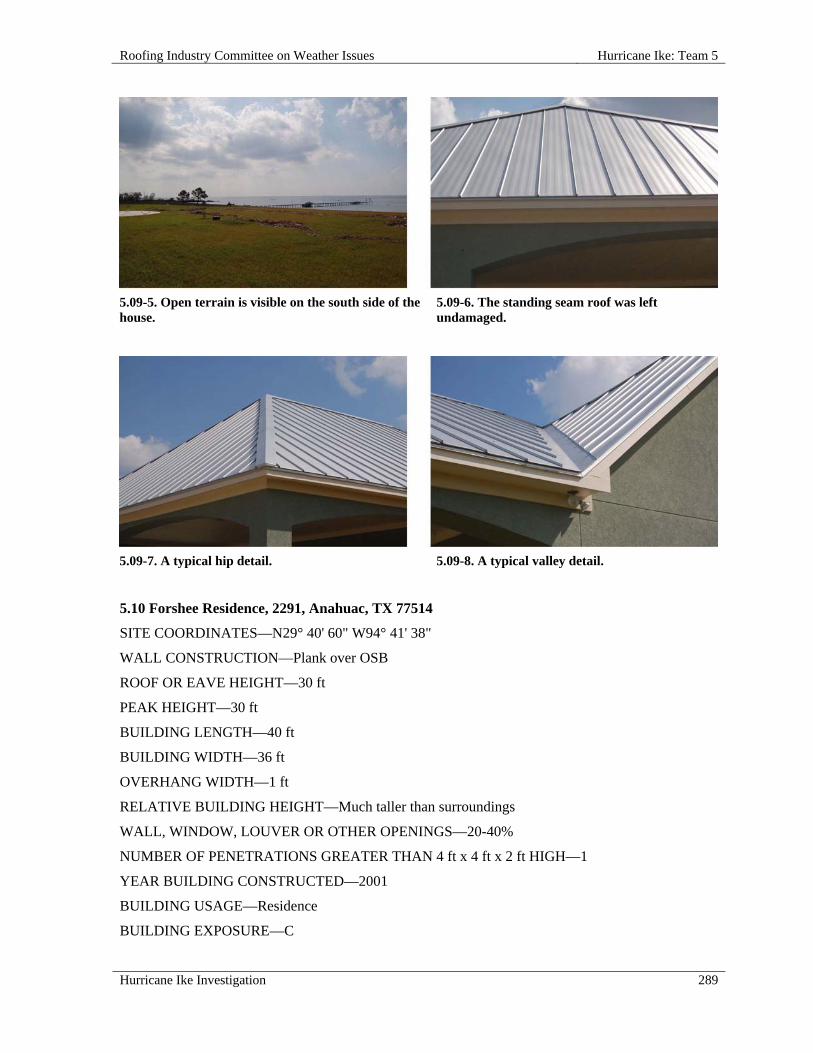
Roofing Industry Committee on Weather Issues Hurricane Ike: Team 5
Hurricane Ike Investigation 289
5.09-5. Open terrain is visible on the south side of the house.
5.09-6. The standing seam roof was left undamaged.
5.09-7. A typical hip detail. 5.09-8. A typical valley detail.
5.10 Forshee Residence, 2291, Anahuac, TX 77514
SITE COORDINATES—N29° 40' 60" W94° 41' 38"
WALL CONSTRUCTION—Plank over OSB
ROOF OR EAVE HEIGHT—30 ft
PEAK HEIGHT—30 ft
BUILDING LENGTH—40 ft
BUILDING WIDTH—36 ft
OVERHANG WIDTH—1 ft
RELATIVE BUILDING HEIGHT—Much taller than surroundings
WALL, WINDOW, LOUVER OR OTHER OPENINGS—20-40%
NUMBER OF PENETRATIONS GREATER THAN 4 ft x 4 ft x 2 ft HIGH—1
YEAR BUILDING CONSTRUCTED—2001
BUILDING USAGE—Residence
BUILDING EXPOSURE—C

Hurricane Ike: Team 5 Roofing Industry Committee on Weather Issues
290 Hurricane Ike Investigation
BUILDING PRESSURIZED—Yes
ASCE 7 BASIC WIND SPEED—120 mph
ACTUAL WIND SPEED—110 mph
WIND SPEED AT ROOFTOP—111 mph
VELOCITY PRESSURE—32 psf
PRIMARY WIND DIRECTION—Perpendicular to long side
ROOF SLOPE—Steep Roof
ROOF TYPE—Asphalt Shingle
TYPE—Architectural
ATTACHMENT—Nails
SECONDARY SUPPORT TYPE—Deck
DECK—Wood
DECK THICKNESS—1/2 in.
INSULATION TYPE—Batt Insulation below deck
UNDERLAYMENT—Felt
RE-COVER—No
PERCENT OF DAMAGE—>0<10%
DAMAGE INITIATION—Perimeter roof edges may have been the starting points for roof damage.
DESCRIBE DAMAGE—Roof damage consisted primarily of perimeter shingles that were broken or detached. Shingles were missing near a ridge at the right front of the house, an eave at right front, and along the right and left sides of the main roof. Shingles with missing tabs were noted at left front.
Significant numbers of plank siding panels were also damaged or detached.
ROOF DAMAGE APPEARED TO BE CAUSED BY:
1. Wind forces exceeded shingle (and siding) design limits.
MISCELLANEOUS NOTES:
1. The Forshee residence, built in 2001, is located several hundred yards north of the Barrington house (Inspection No. 5.09);
2. This house is on stilts 8 ft - 10 ft above grade and is covered with architectural grade asphalt shingles.

Roofing Industry Committee on Weather Issues Hurricane Ike: Team 5
Hurricane Ike Investigation 291
PHOTOGRAPHS OF ROOF DAMAGE
5.10-1. West elevation had a bay exposure.
5.10-2. Area east of the house was open terrain.
5.10-3. More open terrain was noted southeast of the house.
5.10-4. North elevation. Note conspicuous siding damage.
5.10-5. Photo shows both siding and roof damage on the upper section of the east elevation.
5.10-6. Minor roof damage is visible at the northeast corner.

Hurricane Ike: Team 5 Roofing Industry Committee on Weather Issues
292 Hurricane Ike Investigation
5.11 Multi-use Building, 308 Wilcox Street, Anahuac, TX 77514
SITE COORDINATES—N29° 46' 18" W94° 41' 0"
WALL CONSTRUCTION—Metal wall
ROOF OR EAVE HEIGHT—11 ft
PEAK HEIGHT—13 ft
PARAPET HEIGHT—1 ft, west only
BUILDING LENGTH—100 ft
BUILDING WIDTH—75 ft
OVERHANG WIDTH—1 ft
RELATIVE BUILDING HEIGHT—Equal to surroundings
WALL, WINDOW, LOUVER OR OTHER OPENINGS—5-10%
NUMBER OF PENETRATIONS GREATER THAN 4 ft x 4 ft x 2 ft HIGH—1
BUILDING USAGE—Commercial - several small businesses
BUILDING EXPOSURE—B
BUILDING PRESSURIZED—Yes
ASCE 7 BASIC WIND SPEED—120 mph
ACTUAL WIND SPEED—110 mph
WIND SPEED AT ROOFTOP—83 mph
VELOCITY PRESSURE—18 psf
PRIMARY WIND DIRECTION—All
ROOF SLOPE—Steep Roof
ROOF TYPE—Metal Through Fastened
TYPE—Architectural
ATTACHMENT—Nails
SECONDARY SUPPORT TYPE—8 in. zee - unequal legs
SECONDARY SUPPORT SPACING—5 ft
DECK—Wood
DECK THICKNESS—1/2"
INSULATION TYPE—No insulation
SURFACE—Metal Color
METAL—Galvalume
METAL THICKNESS—26 Gauge

Roofing Industry Committee on Weather Issues Hurricane Ike: Team 5
Hurricane Ike Investigation 293
PANEL WIDTH—36 in.
FASTENER SPACING—12 in., 6 in. at laps
RE-COVER—Yes
PERCENT OF DAMAGE—100%
DAMAGE INITIATION—Openings at the eastern soffit allowed roof to pressurize, leading to total blow-off.
DESCRIBE DAMAGE—The entire roof blew off and landed 100 ft west of the building. The roof panels were still attached to some secondary steel zee members. Deteriorated cementitious wood fiber (CWF) soffit panels were also dislodged.
ROOF DAMAGE APPEARED TO BE CAUSED BY:
1. Assisted Soffit Failure - Soffit panels on windward side were blown upward, allowing rapid pressurization of the poorly secured, retrofitted roof;
2. Poor Rafter Attachment - Canopy rafters along east side (front of building) were torch-cut from original 10 in. depth to approximately 2 in. deep at eave ends (apparently for aesthetic reasons); this left little structural strength for attachment to the original building structure; high wind pressure caused lifting of the roof panels, pulling rafters from bolt heads i.e., the overall panel-to-rafter bond was stronger than the rafter-to-structure bond; roof panels continued to lift and then peeled, east to west, by “ripping” purlins from rafters, and rafters from structure; entire roof, with purlins attached, landed 100 ft west of the building;
3. Modes of failure included both purlins pulling over bolt-heads and bolts pulling through rafters.
MISCELLANEOUS NOTES:
1. This single story metal building housed several small businesses;
2. Original roof was a gravel surfaced built-up roof membrane (BUR) on a CWF deck;
3. Roof deck extended beyond walls on north and east sides about 4 ft; deck finished flush with the south wall and terminated at a low parapet at the west wall;
4. Age of the structure was undetermined;
5. Structure was previously retrofitted with a 26 gauge metal roof system over the existing built-up roof membrane (BUR);
6. Based on severe deterioration of the CWF panels along the east overhang, it is likely that the BUR had failed and was leaking;
7. Roof panels were secured to purlins with self-drilling Tek-type fasteners 12 in. apart;
8. For aesthetic effect (achieving a narrow fascia), rafters along the east elevation were tapered with a torch from 10 in. to 2 in. at eave end;
9. The north/south ridge of gabled metal roof had approximately 2:12 slope; 10 in. “C” channel rafters spaced 10 ft apart were bolted to vertical channels, two bolts per connection, also approximately 10 ft apart; secondary supports, 8 in. “zees” spaced 5 ft apart, were bolted to rafters, one bolt per connection;
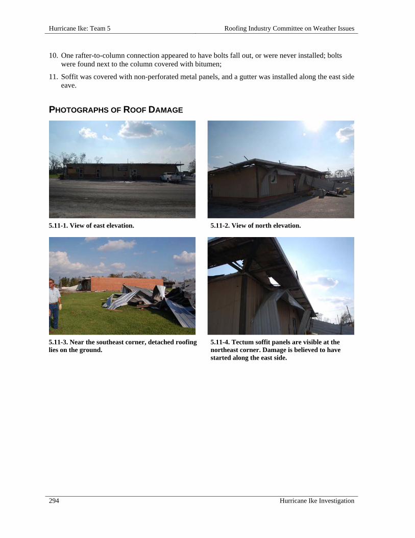
Hurricane Ike: Team 5 Roofing Industry Committee on Weather Issues
294 Hurricane Ike Investigation
10. One rafter-to-column connection appeared to have bolts fall out, or were never installed; bolts were found next to the column covered with bitumen;
11. Soffit was covered with non-perforated metal panels, and a gutter was installed along the east side eave.
PHOTOGRAPHS OF ROOF DAMAGE
5.11-1. View of east elevation. 5.11-2. View of north elevation.
5.11-3. Near the southeast corner, detached roofing lies on the ground.
5.11-4. Tectum soffit panels are visible at the northeast corner. Damage is believed to have started along the east side.

Roofing Industry Committee on Weather Issues Hurricane Ike: Team 5
Hurricane Ike Investigation 295
5.11-5. View of a soffit on the east side. Winds appear to have infiltrated and pressurized the roof though these soffits.
5.11-6. View from the northeast corner.
5.11-7. Retrofitted rafters were cut down from 8 in. to approximately 1/2 in. at roof edges, sacrificing strength.
5.11-8. Note the bent and twisted retrofit rafters.
5.11-9. Loose rafter fasteners found on BUR surface appear to have never been installed, or backed-out prior to roof blow-off.
5.11-10. The blown off roof was found behind the structure.

Hurricane Ike: Team 5 Roofing Industry Committee on Weather Issues
296 Hurricane Ike Investigation
5.12 Cher Hotel, 925 Highway332, Lake Jackson, TX 77566
SITE COORDINATES—N29° 07' 34" W95° 25' 23"
WALL CONSTRUCTION—Brick & stucco
ROOF OR EAVE HEIGHT—17 ft
PEAK HEIGHT—20 ft
PARAPET HEIGHT—14 ft
BUILDING LENGTH—60 ft
BUILDING WIDTH—55 ft
RELATIVE BUILDING HEIGHT—Shorter than surroundings
WALL, WINDOW, LOUVER OR OTHER OPENINGS—10-20%
YEAR BUILDING CONSTRUCTED—1980's
BUILDING USAGE—Hotel / motel
BUILDING EXPOSURE—B
BUILDING PRESSURIZED—Yes
ASCE 7 BASIC WIND SPEED—130 mph
ACTUAL WIND SPEED—90 mph
WIND SPEED AT ROOFTOP—72 mph
VELOCITY PRESSURE—13 psf
PRIMARY WIND DIRECTION—Perpendicular to long side
ROOF SLOPE—Steep Roof
ROOF TYPE—Wood Shingles
ATTACHMENT—Nails
NAILS PER SHINGLE—2
DECK—open spaced 1 in. x 6 in.
INSULATION TYPE—None
RE-COVER—No
PERCENT OF DAMAGE—>50<75%
DAMAGE INITIATION—Equipment screen was point of shingle loss.
DESCRIBE DAMAGE—Cedar shingles were damaged and/or detached from roof mounted equipment screen.

Roofing Industry Committee on Weather Issues Hurricane Ike: Team 5
Hurricane Ike Investigation 297
ROOF DAMAGE APPEARED TO BE CAUSED BY:
1. Improper Fasteners - Blown-off shingles appeared to have been secured with the required two nails per shingle but the nails were severely corroded on underside of shingles, and appeared to offer little or no resistance to blow-off;
2. Openings in Equipment Screen - Screen interior was partially open and susceptible to wind pressurization.
MISCELLANEOUS NOTES:
1. From the ground, there appeared to be a shingle hip roof over solid deck and spaced framing (purlins); rooftop inspection revealed that the “roof” was actually an equipment screen consisting of number one grade cedar shingles installed on a wood frame;
2. Wood shingles were curled, split and pieces missing;
3. It appears the roof has undergone surface modification with some type of coating.
PHOTOGRAPHS OF ROOF DAMAGE
5.12-1. View of the southwest corner. 5.12-2. West elevation; note conspicuous shingle
damage (center).
5.12-3. Rear of the shingled equipment screen. 5.12-4. Inside of the shingle facade.

Hurricane Ike: Team 5 Roofing Industry Committee on Weather Issues
298 Hurricane Ike Investigation
5.12-5. This area lost most of its shingle covering. 5.12-6. View of the shingle layout and nailing
pattern.
5.12-7. On the underside of this blown-off shingle, fasteners were rusted through, offering little pull-out resistance.
5.12-8. Visible here are nails in a blown-off shingle.
5.13 Cher Hotel, 925 Highway 332, Lake Jackson, TX 77566
SITE COORDINATES—N29° 7' 34" W95° 25' 23"
WALL CONSTRUCTION—Brick & stucco
ROOF OR EAVE HEIGHT—17 ft
PEAK HEIGHT—20 ft
PARAPET HEIGHT—14 ft
BUILDING LENGTH—18 ft
BUILDING WIDTH—60 ft
RELATIVE BUILDING HEIGHT—Slightly taller than surroundings
YEAR BUILDING CONSTRUCTED—1980's
Roofing Industry Committee on Weather Issues Hurricane Ike: Team 5
Hurricane Ike Investigation 299
BUILDING USAGE—Hotel / motel
BUILDING EXPOSURE—B
BUILDING PRESSURIZED—Yes
ASCE 7 BASIC WIND SPEED—130 mph
ACTUAL WIND SPEED—90 mph
WIND SPEED AT ROOFTOP—72 mph
VELOCITY PRESSURE—13 psf
PRIMARY WIND DIRECTION—Perpendicular to long side
ROOF SLOPE—Steep Roof
ROOF TYPE—Other Steep Slope Roof
TYPE—Compressed fiberboard tile
ATTACHMENT—Nails - 2 per tile
SECONDARY SUPPORT TYPE—Joists
SECONDARY SUPPORT SPACING—2 in. x 6 in. - 16 in. o.c.
DECK—Wood
UNDERLAYMENT—#30 felt
RE-COVER—No
PERCENT OF DAMAGE—>50<75%
DAMAGE INITIATION—The upper half of the west-facing gabled roof was the starting point.
DESCRIBE DAMAGE—Simulated "tiles" (pressed fiberboard) were damaged and/or detached from roof. All tiles on upper half of west elevation roof blew off. A few tiles on the east elevation were damaged, but remained in place.
ROOF DAMAGE APPEARED TO BE CAUSED BY:
1. Cohesive weakness of simulated tile material board led to fastener pullthrough, and blow-off of tiles.
MISCELLANEOUS NOTES:
1. This small, gabled roof sets atop a low slope roof;
2. The ridge runs approximately north/south;
3. From a distance it appeared this roof was covered with Spanish clay tiles; on closer observation we discovered the tiles were made of pressed fiberboard; apparently this product was offered years ago as a low cost alternate to clay but is no longer marketed.

Hurricane Ike: Team 5 Roofing Industry Committee on Weather Issues
300 Hurricane Ike Investigation
PHOTOGRAPHS OF ROOF DAMAGE
5.13-1. View of the pressed fiberboard tile roof is from the northeast corner.
5.13-2. A closer look at the tiled roof from the same corner. Note missing tiles.
5.13-3. View of terrain south of this roof.
5.13-4. View from the southeast corner shows less tile damage on the south elevation.
5.13-5. The eave and tiled roof on the north elevation.
5.13-6. A closer view of the eave and bottom row of tile (north elevation).
Roofing Industry Committee on Weather Issues Hurricane Ike: Team 5
Hurricane Ike Investigation 301
5.14 Petty Residence, 103 Ingiet Court, Surfside Beach, TX 77541
SITE COORDINATES—N28° 57' 31" W95° 16' 39"
ROOF OR EAVE HEIGHT—35 ft
PEAK HEIGHT—45 ft
BUILDING LENGTH—50 ft
BUILDING WIDTH—60 ft
RELATIVE BUILDING HEIGHT—Slightly taller than surroundings
WALL, WINDOW, LOUVER OR OTHER OPENINGS—40-60%
YEAR BUILDING CONSTRUCTED—2008
BUILDING CODE AT TIME OF CONSTRUCTION—IBC 2006
BUILDING USAGE—Residence
BUILDING EXPOSURE—C
BUILDING PRESSURIZED—Yes
ASCE 7 BASIC WIND SPEED—140 mph
ACTUAL WIND SPEED—90 mph
WIND SPEED AT ROOFTOP—94 mph
VELOCITY PRESSURE—23 psf
PRIMARY WIND DIRECTION—Cornering wind
ROOF SLOPE—Steep Roof
ROOF TYPE—Metal Shingle
TYPE—Stone coated steel shingles
ATTACHMENT—Through-fastened - fasteners 4 in. - 6 in.
SECONDARY SUPPORT TYPE—Joists
DECK—Wood
INSULATION TYPE—Spray polyurethane
INSULATION THICKNESS—14 in.
RE-COVER—No
DAMAGE INITIATION—No damage.
DESCRIBE DAMAGE—This beach house was still under construction using a stone-coated steel shingle system. Although the storm surge undermined the structure, no roof damage was observed. This house is a high-end three story single family residence with a one story observation tower on top, in the center of the roof. The roof is red (clay color) stone-coated steel shingles that appear free of damage.

Hurricane Ike: Team 5 Roofing Industry Committee on Weather Issues
302 Hurricane Ike Investigation
PHOTOGRAPHS OF ROOF DAMAGE
5.14-1. North elevation shows the Gulf of Mexico in the background.
5.14-2. View from the beach shows the south elevation. Note the beach erosion.
5.14-3. A closer view from the beach side. 5.14-4. South exposure is wide open and
unprotected.
5.15 Surf City Beach Rental, 988 Bluewater Highway, Surf City Beach, TX 77541
SITE COORDINATES—N28° 57' 37" W95° 16' 31"
WALL CONSTRUCTION—Wood clap board
ROOF OR EAVE HEIGHT—20 ft
PEAK HEIGHT—27 ft
BUILDING LENGTH—33 ft
BUILDING WIDTH—66 ft
OVERHANG LENGTH—Perimeter
OVERHANG WIDTH—18 in.
RELATIVE BUILDING HEIGHT—Equal to surroundings
WALL, WINDOW, LOUVER OR OTHER OPENINGS—20-40%
YEAR BUILDING CONSTRUCTED—2000
BUILDING USAGE—Vacation residence (rental)

Roofing Industry Committee on Weather Issues Hurricane Ike: Team 5
Hurricane Ike Investigation 303
BUILDING EXPOSURE—C
BUILDING PRESSURIZED—Yes
ASCE 7 BASIC WIND SPEED—140 mph
ACTUAL WIND SPEED—90 mph
WIND SPEED AT ROOFTOP—90 mph
VELOCITY PRESSURE—21 psf
PRIMARY WIND DIRECTION—Perpendicular to short side
ROOF SLOPE—Steep Roof
ROOF TYPE—Asphalt Shingle
TYPE—Architectural
ATTACHMENT—Nails
SECONDARY SUPPORT TYPE—Appears 2 in. x 6 in. @ 16 in. o.c.
SECONDARY SUPPORT SPACING—16 in.
NAILS PER SHINGLE—6
DECK—Wood
DECK THICKNESS—5/8 in.
INSULATION TYPE—Batt Insulation below deck
UNDERLAYMENT—#15 felt
RE-COVER—Yes
PERCENT OF DAMAGE—>25 <50%
DAMAGE INITIATION—Possibly initiated at lower eave section.
DESCRIBE DAMAGE—Except for very minor shingle lifting on the southeast hip, damage was confined to north and west sides.
Damage on the north (landward) side was extensive - an estimated 70% of shingles were blown-off. Westside damage was less severe, confined to detachment of four courses of shingles below the ridge. Very minor damage was noted on hips and to underlayment, and there was no observed damage to the ridge.
ROOF DAMAGE APPEARED TO BE CAUSED BY:
1. Strong Winds, Poor Fastening, and Low-Performance Shingles - Strong north winds initially lifted shingles at the eave, then elsewhere; seal-tabs released easily; strengthening winds then forced shingles to pull loose at over-driven (nails driven too deep, creasing or breaking membrane) nail locations, dislodging shingles;
2. Shingle Pull-Over - Shingles dislodged by pulling free from (“pulling over”) nail heads; no nails were pulled from the deck, but the problem appears to be nails that were over-driven and driven at an angle, so that the down-slope side of head cut into shingles, lowering wind-uplift resistance.

Hurricane Ike: Team 5 Roofing Industry Committee on Weather Issues
304 Hurricane Ike Investigation
MISCELLANEOUS NOTES:
1. This single story beach rental property has a hip roof covered with low-end asphalt shingles; it is built on wood stilts approximately 10 ft high;
2. The observed nail pattern was six nails per shingle, properly spaced and positioned.
PHOTOGRAPHS OF ROOF DAMAGE
5.15-1. North elevation. 5.15-2. South elevation.
5.15-3. Damage on the north side of the roof. 5.15-4. A closer look at roof damage on the north
side.

Roofing Industry Committee on Weather Issues Hurricane Ike: Team 5
Hurricane Ike Investigation 305
5.15-5. Over-driven nails near the ridge. 5.15-6. A close-up view of the ridge shows over-
driven nails.
5.15-7. View of the northwest corner and soffits. 5.15-8. A closer look at
the soffit shown in photo 5.15-7.
5.16 EXXON - Quick-Stop, 2902 FM 523, Oyster Creek, TX 77541
SITE COORDINATES—N29° 59' 57" W95° 19' 40"
WALL CONSTRUCTION—Stucco
ROOF OR EAVE HEIGHT—12 ft
PEAK HEIGHT—13 ft
PARAPET HEIGHT—17 ft
BUILDING LENGTH—75 ft
BUILDING WIDTH—55 ft
RELATIVE BUILDING HEIGHT—Slightly taller than surroundings
WALL, WINDOW, LOUVER OR OTHER OPENINGS—10-20%
NUMBER OF PENETRATIONS GREATER THAN 4 ft x 4 ft x 2 ft HIGH—4

Hurricane Ike: Team 5 Roofing Industry Committee on Weather Issues
306 Hurricane Ike Investigation
BUILDING USAGE—Gas station
BUILDING EXPOSURE—B
BUILDING PRESSURIZED—Yes
ASCE 7 BASIC WIND SPEED—130 mph
ACTUAL WIND SPEED—90 mph
WIND SPEED AT ROOFTOP—68 mph
VELOCITY PRESSURE—12 psf
PRIMARY WIND DIRECTION—Perpendicular to short side
ROOF SLOPE—Low Slope Roof
ROOF TYPE—Modified Bitumen
DECK—Wood
INSULATION ATTACHMENT—Not attached
MEMBRANE ATTACHED TO—Wood deck
ATTACHED WITH—Nails
SURFACE—Granules
PERCENT OF DAMAGE—>50<75%
DAMAGE INITIATION—Roof peel from the edge.
DESCRIBE DAMAGE—Half of the roof was blown off from eave to eave. The other half remained in place but lifted up during the event, possibly compromising its bond.
ROOF DAMAGE APPEARED TO BE CAUSED BY:
1. Nail heads pulled through the roof membrane, and metal roof edge pulled away from building;
2. It was not clear whether edge metal lifted and membrane peeled, or if membrane ballooned and lifted edge metal; in either case, both edge and field membrane were minimally secured, which allowed approximately half of the roof, eave-to-eave, to become dislodged and blow off.
MISCELLANEOUS NOTES:
1. Construction along the roof edge was an interesting combination of concrete masonry units (CMU) wall, foam, glass fiber, roofing membrane, and gun-grade adhesive; it appears that edge metal (lightweight aluminum) was glued with one bead of adhesive, approximately1 in. wide, to a glass fiber scrim on top of expanded polystyrene (EPS) insulation board; nails were driven through the edge metal into the EPS board;
2. The base sheet was fastened with nails through 1 in. diameter plastic washers spaced 24 in. o.c.
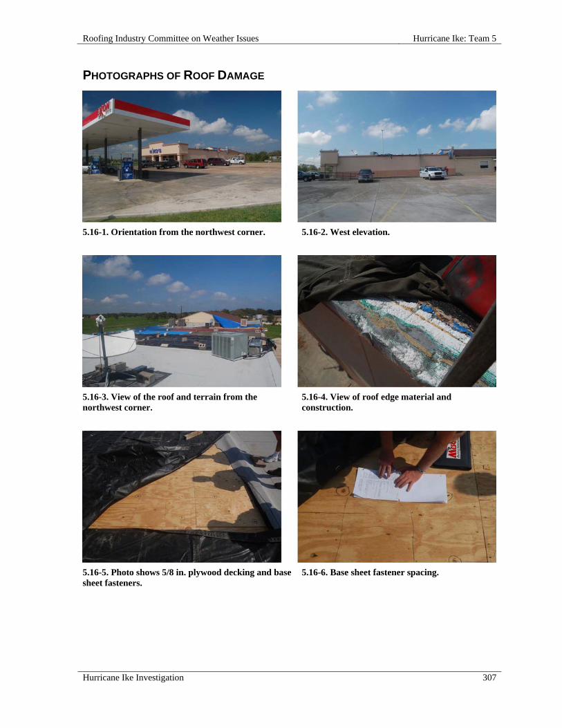
Roofing Industry Committee on Weather Issues Hurricane Ike: Team 5
Hurricane Ike Investigation 307
PHOTOGRAPHS OF ROOF DAMAGE
5.16-1. Orientation from the northwest corner.
5.16-2. West elevation.
5.16-3. View of the roof and terrain from the northwest corner.
5.16-4. View of roof edge material and construction.
5.16-5. Photo shows 5/8 in. plywood decking and base sheet fasteners.
5.16-6. Base sheet fastener spacing.

Hurricane Ike: Team 5 Roofing Industry Committee on Weather Issues
308 Hurricane Ike Investigation
5.16-7. Blown-off roofing was piled on the ground. 5.16-8. Metal caps and fasteners were used to
secure the roof assembly.
5.16-9. Another view of metal caps and fasteners used to secure the roof assembly.
5.16-10. Edge metal and fasteners are shown here.

Roofing Industry Committee on Weather Issues Hurricane Ike: Conclusions
Hurricane Ike Investigation 309
CONCLUSIONS
RESULTS There was little exposure to the current code design wind speeds; some of the roofs that were damaged were built before the current wind requirements were in place. The general observation is that when the roofs appeared to be designed to current codes and installed using good workmanship, the roofs were not damaged, or at most, suffered minor damage. No system performed flawlessly. Fully adhered roofs when damaged generally had more subsequent interior damage to the buildings, as large sections of membrane were likely to be displaced. Single ply roofs were subject to damage due to flying debris, which usually resulted in minor small leaks. Securing rooftop units and metal edging can reduce damage caused by flying debris. The phenomenon of wind streaks made it difficult to assess relative damage. Hurricane winds are generally more consistent near the coastal landfall, but hurricanes are found to have steaks greater than the mean wind speed and areas where the wind speeds are less than the mean wind speed. This streak phenomenon was very evident in the inland areas affected by Ike. This makes the values for wind speeds at any given site in this report less reliable. Previous hurricane events involved investigations of damage within 15 miles of the hurricane landfall, whereas most of the Hurricane Ike investigations involved buildings greater than 15 miles from landfall. The wind speeds in the report are from the Applied Research Associates’ (ARA) map (Appendix A) and the same map superimposed with ASCE wind zones (Appendix B), however the wind speeds in small areas could be significantly different from the wind speeds reported because of the wind streak phenomenon. After Hurricane Ike very large differences in total damage were observed within small distances. This was not observed in the previous RICOWI hurricane inspections. The four years since RICOWI’s first hurricane investigation is too short a time to determine if progress is being made in installation practices, as many roofs are 15 or more years old. Roofs installed in the last ten years appeared to perform better than older systems.
FUTURE RESEARCH Continued product development is encouraged. An industry goal must be the development of robust systems that resist punctures, are not subject to wind damage, are not progressively damaged and are easy to install. Static testing of roofs does not capture the peel phenomenon. In static testing, roofs are considered to fail at the onset of peel, but the tests do not subject the system to the same force likely encountered when the edge or other areas fail and membrane or metal starts to catch wind like a sail. Preventing progressive failure would result in significant limitation of interior damage. Typically, testing of some metal roof systems evaluate the panel to clip connections and the panel and clip to substrate connections. When the uplift resistance of a roofing material is dependent on the attachment of a perimeter edge metal, like some metal roof systems, the evaluation of that roofing resistance should also incorporate the perimeter attachment of all of the related components in the system and other related flashing conditions.

Hurricane Ike: Conclusions Roofing Industry Committee on Weather Issues
310 Hurricane Ike Investigation
Currently ASTM E1592 Standard Test Method for Structural Performance of Sheet Metal Roof and Siding Systems by Uniform Static Air Pressure Difference requires that end and edge metal restraints must be representative of field conditions. Given that several metal roofs failed at these points, improved documentation of the age of the roof should be noted in future investigations to try to support that the test method is adequate to prevent perimeter and edge flashing problems.
NEED ENGINEERED DESIGN This investigation again revealed that installations that were not installed by professional roofers or engineered by knowledgeable designers were found to be prone to damage. Weather protection of a building is primary to sustainability of the building. Fortunately, many roofing associations and other roof industry organizations offer excellent educational programs and design information for those interested in increasing their knowledge of roof wind considerations. What is needed most is for that knowledge to spread to all those involved in system design and installation. Although a miracle new roofing system may be developed, no system fits all roofs and therefore the fundamental principles need to be understood and taught to all involved. The industry has made great progress in understanding the wind loads on roofs and providing systems that resist the loads. Having that knowledge applied, especially in hurricane prone regions, could result in huge savings when a storm hits. Suggestions to enhance wind resistance of roof coverings:
Design/construct roof coverings in accordance with available high wind design guidelines (e.g., ASCE 7, ANSI/SPRI ES-1, FM Global LPDS 1-49) and roofing materials manufacturers’ instructions;
Design/construct roof coverings to limit air flow between roof coverings and roof decks; Specify roof systems designed for the anticipated slope; Use conservatively durable materials as part of roof attachment systems (e.g., corrosion-
resistant screws; stainless steel fasteners, preservative treated wood) where the possibility exists of exposure of these elements to long term moisture conditions;
Prior to roofing installation, perform pull-out testing of fasteners to confirm required load capacity;
Before roof covering installation, confirm wood nailers are adequately secured; we are not aware of an industry recognized method to field test wood nailers and we recommend that such a test or protocol be developed, however, ANSI/SPRI/FX-1 can be used to determine the edge fastener pull-out, as well as the field of the roof fasteners;
Install cleats onto vertical fascia using metal of adequate thickness for specified panel gauge e.g., 20 gauge cleat for 24 gauge panels, and using the appropriate fastening pattern;
Nominal 5/8 in. to 3/4 in. aggregate-surfaced roofs over 30 ft in height with flush perimeter-edge constructions - apply double application of flood coat and aggregate; remove remnant loose aggregate;
Secure mechanical equipment against wind displacement.
THE VALUE OF THESE INVESTIGATIONS Previous investigations have resulted in proposed code changes, product modifications and enhanced installation details. Participation by industry members have resulted in an improved understanding of how systems respond to wind and have resulted in specifications being adjusted to take into consideration the subtleties that may otherwise be overlooked. Insurance providers have been able to see systems that work and provide information to those setting rates. Academic and research

Roofing Industry Committee on Weather Issues Hurricane Ike: Conclusions
Hurricane Ike Investigation 311
laboratory participants have seen the results of previous research and determined areas where more research may yield meaningful results.
FUTURE INVESTIGATIONS The majority of RICOWI’s Sponsor Members have agreed there is a need to conduct an investigation of an “above code event.” RICOWI’s Board of Directors appointed a task force that has developed the new protocol. Check RICOWI’s website for updates on future investigations (www.ricowi.com).


Roofing Industry Committee on Weather Issues Hurricane Ike: Bibliography
Hurricane Ike Investigation 313
BIBLIOGRAPHY
UPDATED MANUFACTURER APPLICATION GUIDELINES, MANUALS, CODE AND
TECHNICAL PUBLICATIONS ARMA Asphalt Roofing Residential Manual and New Wind Standards for Asphalt Shingles, Asphalt Roofing Manufacturers Association, Washington, DC, 2006
ASCE 7-05, American Society of Civil Engineers, Reston, VA
CSA Number A123.21-04, Standard Test Method for the Dynamic Wind Uplift Resistance of Mechanically Attached Membrane Roofing Systems, Canadian Standards Association, Mississauga, Ontario, 2004
Concrete and Clay Roof Tile Installation Guide, Fourth Edition, Florida Roofing, Sheet Metal and Air Conditioning Association, Winter Park, FL and Tile Roofing Institute, Chicago, IL, 2005
Factory Mutual Global Loss Prevention Data Sheet I-49, Factory Mutual Global, Norwood, MA, 2000
Flexible Membrane Roofing: A Professional’s Guide to Specifications, Single Ply Roofing Industry, Inc., Waltham, MA, 2004
Florida Building Code, Florida Department of Community Affairs, Tallahassee, FL, 2005
Guide for Selection of Elastomeric Protective Coatings over Sprayed Polyurethane Foam, AY 102, Spray Polyurethane Foam Alliance, Fairfax, VA, 2004
Guide for the Wind Design of Mechanically Attached Flexible Membrane Roofs, Baskaran, A.; Smith, T.L., National Research Council Canada, Ottawa, Ontario, 2005
Guide Specifications for Residential Metal Roofing, Metal Construction Association, Glenview, IL, 2004
International Building Code & International Residential Code, International Code Council Inc., Washington, DC
Metal Building Systems Manual, Metal Building Manufacturers Association, Cleveland, OH, 2006
Metal Roofing Systems Design Manual, Metal Building Manufacturers Association, Cleveland, OH, 2000
Minimum Design Loads for Buildings and Other Structures, ASCE 7, Structural Engineering Institute of the American Society of Civil Engineers, Reston, VA
New Roof Construction Manual, Cedar Shake and Shingle Bureau, Sumas, WA, 2009
Spray Polyurethane Foam Systems for New and Remedial Roofing, AY 104, Spray Polyurethane Foam Alliance, Fairfax, VA, 2008
Standard Field Test Procedure for Determining the Withdrawal Resistance of Roofing Fasteners, ANSI/SPRI/ FX-1, American National Standards Institute, Washington, DC and Single Ply Roofing Industry, 2006
Wind Design Guide for Edge Systems Used with Low Slope Roofing Systems, ANSI/SPRI/ES-1, American National Standards Institute, Washington, DC and Single Ply Roofing Industry, 2003


Roofing Industry Committee on Weather Issues Hurricane Ike: Acknowledgments
Hurricane Ike Investigation 315
ACKNOWLEDGMENTS RICOWI thanks several organizations, corporations, and individuals for supporting the program and contributing to our fourth successful hurricane investigation. Our gratitude extends to: The RICOWI Sponsor Members who provided monetary and/or personnel support for the project-
Asphalt Roofing Manufacturers Association Cedar Shake and Shingle Bureau Insurance Institute for Business and Home Safety International Staple, Nail and Tool Association Metal Building Manufacturers Association Metal Construction Association National Research Council of Canada Roof Consultants Institute, Inc. / The Institute of Roofing, Waterproofing, & Building Envelope Professionals Oak Ridge National Laboratory Spray Polyurethane Foam Alliance Single Ply Roofing Industry Tile Roofing Institute
RICOWI Affiliate Members that provided input for the on-going program development Oak Ridge National Laboratory (ORNL), for publishing; specifically, we are very grateful for the
efforts by Walter Koncinski and Brenda Walker in formatting and compiling the final report Teresa Williams (ORNL) for the production of the hard copies of the report Roof Consultants Institute Foundation for a grant to supplement the publication costs of this
report The Logistics Team for donating the additional time required to deploy the day after landfall to
the damage area, conduct an aerial surveillance, target investigation sites and handle logistics Warren French and the French Engineering, Inc. staff John Goveia Phil Mayfield Paul Riesebieter Robb Smith
Skydive Houston for accommodating our request for an immediate flyover of the damage area Contributing Report Writers:
Mike Barton Bas Baskaran Vickie Crenshaw Phil Dregger John Goveia David Hunt
Joe Malpezzi Phil Mayfield William Morgan David Roodvoets Walt Rossiter William Woodring Patricia Wood-Shields

Hurricane Ike: Acknowledgments Roofing Industry Committee on Weather Issues
316 Hurricane Ike Investigation
The investigation team members for their time, long hours in the field and assistance in preparing the reports:
Mike Barton, ARMKO Industries Bas Baskaran, National Research Council of Canada Mike Bryson, Bryson Company Jim Bush, Atas International, Inc. Vickie Crenshaw, Crenshaw Consulting Group Doug Dewey, State Farm Insurance André Desjarlais, Oak Ridge National Laboratory Phil Dregger, Technical Roof Services, Inc. / RCI Peter Garrigus, Trufast Corporation John Goveia, Technical Roof Services, Inc. / RCI Steve Heil, Mesco Building Solutions / MBMA Dave Hunt, Revere Copper Products, Inc. Mason Knowles, Mason Knowles Consulting John Kurtz, ISANTA Bob LeClare, WP Hickman Company Joe Malpezzi, Carlisle SynTec Corporation Phil Mayfield, PSM Consultants Glenn Miller, GAF Materials Corporation Bill Morgan, Malarkey Roofing Products Roger Morrison, Deer Ridge Consulting, Inc. / SPFA Paul Riesebieter, Malarkey Roofing Products Dave Roodvoets, DLR Consultants / SPRI Walter Rossiter, WJ Rossiter & Associates / RCI Reinhard Schneider, Georgia Pacific Gypsum Robb Smith, Amtech Building Sciences, Inc. / RCI Joe Strickland, GAF Materials Corporation / ARMA & SPRI Bobby Whitman, GAF Materials Corporation Bill Woodring, GAF Materials Corporation / ARMA Patty Wood-Shields, RICOWI, Inc.
The photographers for the numerous hours required to sort and caption photographs Phil Mayfield who once again took on the task of editing and peer reviewing the first draft of all
team reports Robert Wardlaw for another outstanding job as the final peer reviewer Lance Robinson, FileMaker Pro software consultant, for training and report formatting Applied Research Associates & Delorme Street Atlas USA for providing wind speed maps Google Earth for aerial images Jack Colley and Gregory Pekar of the Texas Division of Emergency Management for their
cooperation in providing a clearance document, which allowed our teams access into the declared and non-declared disaster areas consistent with public safety
Facility managers for their cooperation at the properties inspected The people in the hurricane-ravaged areas for their cooperation and hospitality.

Roofing Industry Committee on Weather Issues Hurricane Ike: Acknowledgments
Hurricane Ike Investigation 317
SPECIAL ACKNOWLEDGEMENT Team 6 Captain, Mike Barton, was tragically drowned in a sailboat accident March 22, 2009. Mike joined RICOWI as an Affiliate Member in March 2000. In addition to participating in the Hurricane Ike investigation, he was active on the Hail Committee and served as a team member during the Oklahoma City hail storm investigation. Mike imparted his knowledge of roofing products and industry standards to ensure better roofing systems. He had completed the Ike Team 6 report draft prior to the accident but a computer virus had corrupted the report. RICOWI would like to thank his administrative assistant, Vickie Burdett, for her efforts in working with us to recover data/photos and restore the report. We extend our sincere thanks to ARMKO for supporting Mike’s participation in RICOWI’s programs.


APPENDICES
A. IKE—3-SECOND PEAK GUST WIND SPEED MAP Courtesy of Applied Research Associates
B. IKE—3-SECOND PEAK GUST WIND SPEED MAP SUPERIMPOSED WITH ASCE WIND ZONES Courtesy of Applied Research Associates and Technical Roof Services, Inc.
C. AERIAL SURVELLANCE ROUTE Courtesy of © 2010 DeLorme Street Atlas USA®
D. INVESTIGATION TEAM GROUP PHOTO
E. SAFFIR-SIMPSON HURRICANE SCALE Courtesy of the National Hurricane Center
F. RICOWI INFORMATION
G. INSPECTION REPORTS LISTED BY TEAM
H. INSPECTIONS BY ROOF TYPE

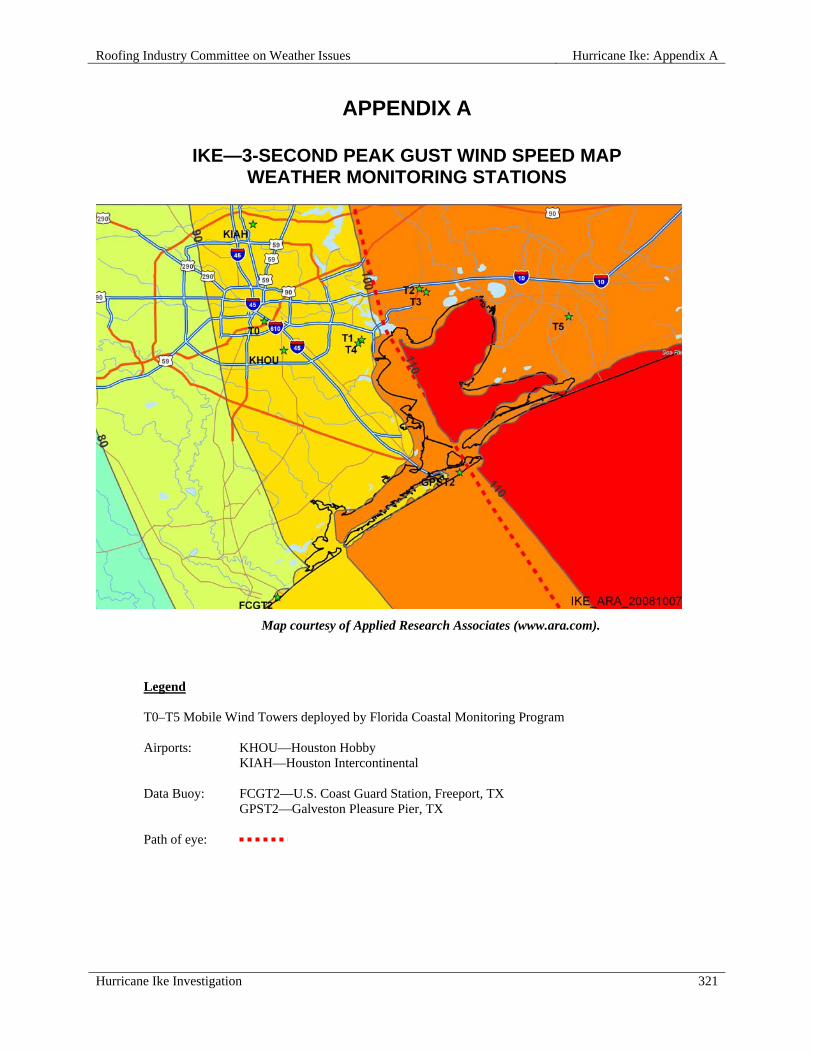
Roofing Industry Committee on Weather Issues Hurricane Ike: Appendix A
Hurricane Ike Investigation 321
APPENDIX A
IKE—3-SECOND PEAK GUST WIND SPEED MAP WEATHER MONITORING STATIONS
Map courtesy of Applied Research Associates (www.ara.com).
Legend T0–T5 Mobile Wind Towers deployed by Florida Coastal Monitoring Program Airports: KHOU—Houston Hobby
KIAH—Houston Intercontinental Data Buoy: FCGT2—U.S. Coast Guard Station, Freeport, TX GPST2—Galveston Pleasure Pier, TX Path of eye:


Roofing Industry Committee on Weather Issues Hurricane Ike: Appendix B
Hurricane Ike Investigation 323
APPENDIX B
IKE—3-SECOND PEAK GUST WIND SPEED MAP OVERLAID WITH ASCE WIND ZONES
Underlaid wind speed map courtesy of Applied Research Associates (www.ara.com).
Wind zone overlay courtesy of Technical Roof Services, Inc.
Legend T0–T5 Mobile Wind Towers deployed by Florida Coastal Monitoring Program Airports: KIAH—Houston Intercontinental KLCH—Lake Charles KBPT—South Texas Regional, Beaumont / Port Arthur KSHV—Shreveport Regional Data Buoy FCGT2—U.S. Coast Guard Station, Freeport, TX GPST2—Galveston Pleasure Pier, TX ASCE Wind Zones:


Roofing Industry Committee on Weather Issues Hurricane Ike: Appendix C
Hurricane Ike Investigation 325
APPENDIX C
HURRICANE IKE – AERIAL SURVEILLANCE ROUTE
Map courtesy of © 2010 DeLorme (www.delorme.com) Street Atlas USA®
HOUSTON

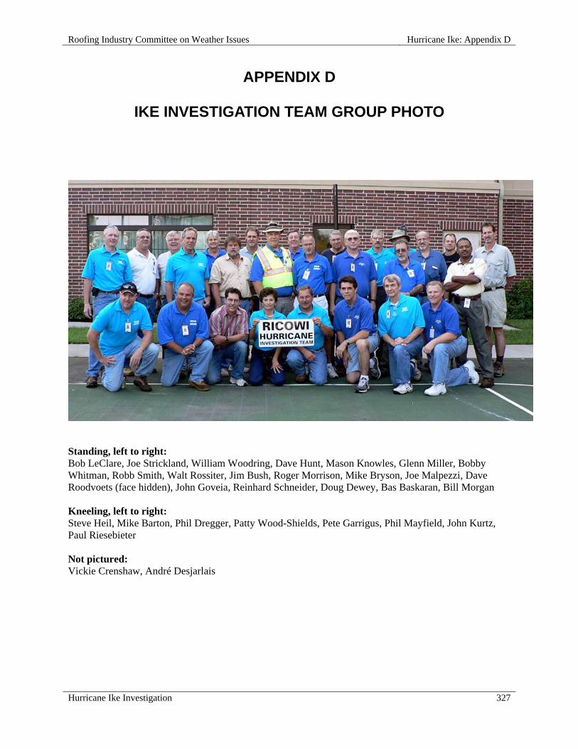
Roofing Industry Committee on Weather Issues Hurricane Ike: Appendix D
Hurricane Ike Investigation 327
APPENDIX D
IKE INVESTIGATION TEAM GROUP PHOTO
Standing, left to right: Bob LeClare, Joe Strickland, William Woodring, Dave Hunt, Mason Knowles, Glenn Miller, Bobby Whitman, Robb Smith, Walt Rossiter, Jim Bush, Roger Morrison, Mike Bryson, Joe Malpezzi, Dave Roodvoets (face hidden), John Goveia, Reinhard Schneider, Doug Dewey, Bas Baskaran, Bill Morgan Kneeling, left to right: Steve Heil, Mike Barton, Phil Dregger, Patty Wood-Shields, Pete Garrigus, Phil Mayfield, John Kurtz, Paul Riesebieter Not pictured: Vickie Crenshaw, André Desjarlais

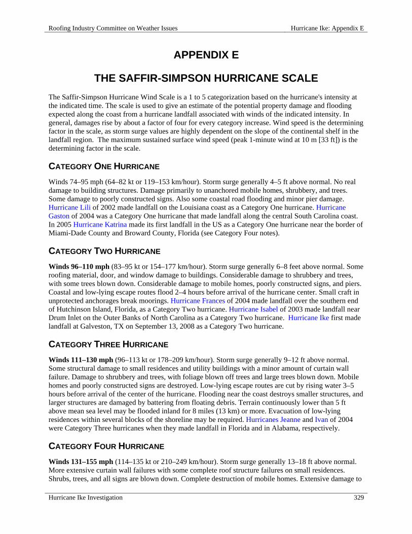
Roofing Industry Committee on Weather Issues Hurricane Ike: Appendix E
Hurricane Ike Investigation 329
APPENDIX E
THE SAFFIR-SIMPSON HURRICANE SCALE The Saffir-Simpson Hurricane Wind Scale is a 1 to 5 categorization based on the hurricane's intensity at the indicated time. The scale is used to give an estimate of the potential property damage and flooding expected along the coast from a hurricane landfall associated with winds of the indicated intensity. In general, damages rise by about a factor of four for every category increase. Wind speed is the determining factor in the scale, as storm surge values are highly dependent on the slope of the continental shelf in the landfall region. The maximum sustained surface wind speed (peak 1-minute wind at 10 m [33 ft]) is the determining factor in the scale.
CATEGORY ONE HURRICANE
Winds 74–95 mph (64–82 kt or 119–153 km/hour). Storm surge generally 4–5 ft above normal. No real damage to building structures. Damage primarily to unanchored mobile homes, shrubbery, and trees. Some damage to poorly constructed signs. Also some coastal road flooding and minor pier damage. Hurricane Lili of 2002 made landfall on the Louisiana coast as a Category One hurricane. Hurricane Gaston of 2004 was a Category One hurricane that made landfall along the central South Carolina coast. In 2005 Hurricane Katrina made its first landfall in the US as a Category One hurricane near the border of Miami-Dade County and Broward County, Florida (see Category Four notes).
CATEGORY TWO HURRICANE
Winds 96–110 mph (83–95 kt or 154–177 km/hour). Storm surge generally 6–8 feet above normal. Some roofing material, door, and window damage to buildings. Considerable damage to shrubbery and trees, with some trees blown down. Considerable damage to mobile homes, poorly constructed signs, and piers. Coastal and low-lying escape routes flood 2–4 hours before arrival of the hurricane center. Small craft in unprotected anchorages break moorings. Hurricane Frances of 2004 made landfall over the southern end of Hutchinson Island, Florida, as a Category Two hurricane. Hurricane Isabel of 2003 made landfall near Drum Inlet on the Outer Banks of North Carolina as a Category Two hurricane. Hurricane Ike first made landfall at Galveston, TX on September 13, 2008 as a Category Two hurricane.
CATEGORY THREE HURRICANE
Winds 111–130 mph (96–113 kt or 178–209 km/hour). Storm surge generally 9–12 ft above normal. Some structural damage to small residences and utility buildings with a minor amount of curtain wall failure. Damage to shrubbery and trees, with foliage blown off trees and large trees blown down. Mobile homes and poorly constructed signs are destroyed. Low-lying escape routes are cut by rising water 3–5 hours before arrival of the center of the hurricane. Flooding near the coast destroys smaller structures, and larger structures are damaged by battering from floating debris. Terrain continuously lower than 5 ft above mean sea level may be flooded inland for 8 miles (13 km) or more. Evacuation of low-lying residences within several blocks of the shoreline may be required. Hurricanes Jeanne and Ivan of 2004 were Category Three hurricanes when they made landfall in Florida and in Alabama, respectively.
CATEGORY FOUR HURRICANE
Winds 131–155 mph (114–135 kt or 210–249 km/hour). Storm surge generally 13–18 ft above normal. More extensive curtain wall failures with some complete roof structure failures on small residences. Shrubs, trees, and all signs are blown down. Complete destruction of mobile homes. Extensive damage to
Hurricane Ike: Appendix E Roofing Industry Committee on Weather Issues
330 Hurricane Ike Investigation
doors and windows. Low-lying escape routes may be cut by rising water 3–5 hours before arrival of the center of the hurricane. Major damage to lower floors of structures near the shore. Terrain lower than 10 ft above sea level may be flooded, requiring massive evacuation of residential areas as far inland as 6 miles (10 km). Hurricane Charley of 2004 was a Category Four hurricane that made landfall in Charlotte County, Florida, with winds of 150 mph. Hurricane Dennis of 2005 struck the island of Cuba as a Category Four hurricane. Hurricane Katrina of 2005 made its second landfall as a Category Four hurricane in Plaquemines Parish near Buras, Louisiana.
CATEGORY FIVE HURRICANE
Winds greater than 155 mph (135 kt or 249 km/hour). Storm surge generally greater than 18 ft above normal. Complete roof failure on many residences and industrial buildings. Some complete building failures with small utility buildings blown over or away. All shrubs, trees, and signs blown down. Complete destruction of mobile homes. Severe and extensive window and door damage. Low-lying escape routes are cut by rising water 3–5 hours before arrival of the center of the hurricane. Major damage to lower floors of all structures located less than 15 ft above sea level and within 500 yards of the shoreline. Massive evacuation of residential areas on low ground within 5–10 miles (8–16 km) of the shoreline may be required. Only three Category Five hurricanes have made landfall in the United States since records began: The Labor Day Hurricane of 1935, Hurricane Camille (1969), and Hurricane Andrew in August, 1992. The 1935 Labor Day Hurricane struck the Florida Keys with a minimum pressure of 892 mb—the lowest pressure ever observed in the United States. Hurricane Camille struck the Mississippi Gulf Coast, causing a 25-foot storm surge that inundated Pass Christian. Hurricane Andrew of 1992 made landfall over southern Miami-Dade County, Florida, causing $ 26.5 billion in losses—the costliest hurricane on record. In addition, Hurricane Wilma of 2005 was a Category Five hurricane at peak intensity when it made landfall in Mexico; it is the strongest Atlantic tropical cyclone on record with a minimum pressure of 882 mb.
Courtesy of the National Hurricane Center

Roofing Industry Committee on Weather Issues Hurricane Ike: Appendix F
Hurricane Ike Investigation 331
APPENDIX F
RICOWI INFORMATION
BACKGROUND
In 1989, Oak Ridge National Laboratory (ORNL) held two workshops devoted to identifying and discussing roof wind uplift issues and alternatives. Important technical issues that were discussed included
Dynamic testing of roof systems The importance of sample size for tests The roles of wind tunnels and air retarders The need for acceptable procedures for ballasted systems. Field data and response team reports The general lack of communication within the roofing industry as to what the problems are, what
is being done and should be done to alleviate them, and how effectively information is transferred within the roofing industry and to others in the building community
At the conclusion of the workshops, a consensus recommendation was to form a committee to address
these matters. The Roofing Industry Committee on Wind Issues (RICOWI) was established, and the charter was approved on October 11, 1990.
In 1996, RICOWI was incorporated as a nonprofit corporation devoted to research and education on
wind issues. After a review of the need for similar types of education and research in the areas of hail, energy efficiency, and durability effects, the organization’s objectives were broadened in 1999 to include other weather topics; and “Wind” in RICOWI’s name was changed to “Weather” to reflect the expanded scope. RICOWI is assisted by ORNL, the banner organization.
MISSION
RICOWI is committed to 1. Encouraging and coordinating research to provide a more comprehensive information base on
roof issues, including wind, hail, energy efficiency, and durability effects;
2. Accelerating the establishment of new or improved industry consensus standard practices for weather design and testing where they are needed;
3. Improving the understanding of roof weather concepts and issues within the building community in general.
MEETINGS
RICOWI meetings are held twice a year, in the spring and fall. The spring meeting is usually in conjunction with the spring seminar, which is scheduled to coincide with the annual convention of the Roof Consultants Institute. RICOWI meetings are attended by people who are concerned about roofing and weather issues.
The meetings include a business session in which the direction and business of RICOWI are
discussed, as well as a technical forum. During the latter segment, the Sponsor and Affiliate members have an opportunity to report on the latest developments in their organizations and on technical subjects
Hurricane Ike: Appendix F Roofing Industry Committee on Weather Issues
332 Hurricane Ike Investigation
of common interest. Participants can bring knowledge or concerns to a group of experts who can review ideas, suggest tests or procedures, or provide feedback on the efficacy of proposed designs, approaches, or solutions.
SEMINARS
Seminars on the proper design, installation, and testing procedures for specific roofing materials are held once or twice a year. Fall seminars are usually held at research, testing, or educational facilities and include a tour. They are of interest to roofing professionals, architects, contractors, engineers, facility managers, and those in the insurance industry.
HURRICANE AND HAIL INVESTIGATION PROGRAMS
RICOWI has implemented two strategic investigation programs: Wind Investigation Program (WIP) Hail Investigation Program (HIP)
The scope of these programs is to investigate the field performance of roofing assemblies after major hurricane and hailstorm
events; factually describe roof assembly performance and modes of damage; formally report the results for substantiated hurricane/hail events.
The data collected provide unbiased, detailed information on the wind and hail resistance of low slope
and steep slope roofing systems from credible investigative teams. The goal is to have a greater industry understanding of what causes roofs to perform or fail in severe wind and hail events. This understanding can lead to overall improvements in roof system durability, reduction of waste generation from re-roofing, and reduction of insurance losses, which may lead to lower overall costs for the public. The reports and multimedia presentations document roofing systems that fail or survive major weather events and provide educational materials to help roofing professionals design wind- and hail-resistant roofing systems. All data are available to be used to improve building codes and roofing design and to educate the industry and the public.
WIND INVESTIGATION PROGRAM
Subsequent to RICOWI’s formation, other concerns were raised. The insurance industry conveyed its concern regarding excessive property loss from wind damage. In recent updates, industry experts estimated that from 1988-2007 insured disaster losses totaled $310.7 billion (2007 dollars). Tropical systems (including hurricanes and tropical storms) accounted for nearly half of all catastrophe losses (source: 2009 Insurance Fact Book, page 115).
Ten of the costliest hurricanes in U.S. history have impacted Florida. According to the Florida
Hurricane Fact Sheet, Hurricane Andrew topped the list at $23.8 billion, followed by Wilma $9.2 billion, Charley $8.5 billion, Ivan $4.9 billion and Katrina $598.6 million (2008 dollars).
The costliest hurricane to hit Texas in recent years was Hurricane Ike. The Texas Hurricane Fact
Sheet states insured property damage caused by Ike in Texas totaled $9.8 billion, based on information from ISO (property/casualty insurance risk company). These losses do not include damage from flooding, which typically is not covered in standard homeowners’ insurance policies. The insurance

Roofing Industry Committee on Weather Issues Hurricane Ike: Appendix F
Hurricane Ike Investigation 333
industry supported RICOWI’s initiative to investigate damage in the aftermath of hurricanes and report the findings.
There is an essential link between product research, performance, and the model building codes. The
International building codes have moved more toward “objective-based codes” versus “prescriptive codes.” Performance requirements are generally perceived to be requirements stated in a way that allows flexibility in the choice of solutions to satisfy the requirements. As such, they are based upon explicit objectives. Code changes are being adopted by the code groups without adequate industry input. In addition, there is a general feeling that the right types of data have not been gathered following events that cause extensive damage from wind.
There is no question that all roofing products and systems of all roofing associations must meet more
rigorous requirements. These products and systems will be subject to tougher scrutiny by building departments, as we have already seen in Dade and Broward counties in Florida and several counties in Texas and other states in hurricane prone areas. Industry involvement in follow-up of wind events is imperative.
RICOWI and the U.S. Department of Energy (DOE)/ORNL responded to these concerns by entering
into a Cooperative Research and Development Agreement (CRADA) to facilitate the WIP. The Program includes all of the major roofing trade associations in North America.
This Program puts credible people in the field who have the required product knowledge and program
training to ensure that sound, scientific, and unbiased reporting occurs. RICOWI’s goal is that buildings will be safer, property losses will be reduced, and the industry will meet the challenge with clear insight as to the needed direction. The reports generated by our investigation teams and findings will be used to educate, as well as to improve products, installation techniques, and safety. They should also reduce overall roofing and insurance costs for the industry, as well as provide a valuable resource to the Federal Emergency Management Agency and state emergency management agencies.
CRADA AND U.S. GOVERNMENT PARTICIPATION
In 1996 RICOWI entered into a CRADA with UT-Batelle, LLC (the contractor that manages ORNL) under the auspices of DOE. The CRADA is jointly funded by DOE’s Office of Energy Efficiency and Renewable Energy, Building Technologies Program; state and community sector programs; and industry partners. The sponsoring associations supplied other major funding, and their individual companies provided in-kind funds to support the CRADA by covering inspectors’ costs for travel and labor.
The scope of work under the CRADA was to investigate and report the field performance of low
slope and steep slope roofing systems after major hurricanes (i.e., those with wind speeds of 95 mph, sustained for 1 minute or more) make landfall on the continental United States in populated areas.
ORNL has been working with private industry to accelerate the acceptance of more energy-efficient
and durable roofing systems. ORNL facilitated the training and issuance of identification badges for RICOWI team members. The CRADA remained in effect until the conclusion of the Hurricane Katrina Investigation. RICOWI continues with this established program.
Following this report will be the development of educational tools illustrating how to design and
construct more durable and energy-efficient roofs, and pointing out the consequences of falling short. A profile will be developed of the performance of various roofing systems in severe wind events, leading to overall improvement in roof system durability, the reduction of waste generation from reroofing, and reduction in insurance losses. These should lead to lower overall costs for the public.

Hurricane Ike: Appendix F Roofing Industry Committee on Weather Issues
334 Hurricane Ike Investigation
Published Report
RICOWI published the Hurricane Charley, Ivan and Katrina Wind Investigation Reports and posted them on its website. This Hurricane Ike Wind Investigation Report will also be posted on RICOWI’s website. Contact Information
Joan Cook, Executive Director Patty Wood-Shields, Special Programs Administrator Email: [email protected] Email: [email protected] www.ricowi.com

Roofing Industry Committee on Weather Issues Hurricane Ike: Appendix G
Hurricane Ike Investigation 335
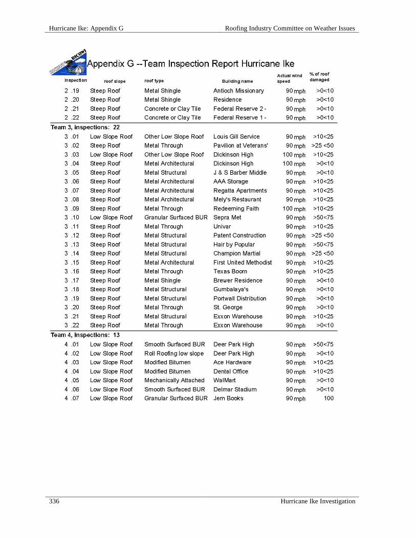
Hurricane Ike: Appendix G Roofing Industry Committee on Weather Issues
336 Hurricane Ike Investigation

Roofing Industry Committee on Weather Issues Hurricane Ike: Appendix G
Hurricane Ike Investigation 337
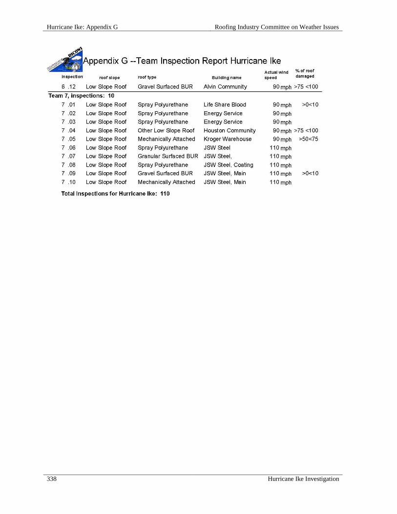
Hurricane Ike: Appendix G Roofing Industry Committee on Weather Issues
338 Hurricane Ike Investigation

Roofing Industry Committee on Weather Issues Hurricane Ike: Appendix H
Hurricane Ike Investigation 339

Hurricane Ike: Appendix H Roofing Industry Committee on Weather Issues
340 Hurricane Ike Investigation

Roofing Industry Committee on Weather Issues Hurricane Ike: Appendix H
Hurricane Ike Investigation 341

Hurricane Ike: Appendix H Roofing Industry Committee on Weather Issues
342 Hurricane Ike Investigation