huntington east division standard time g.m. williams, iii general manager csx transportation...
TRANSCRIPT
HUNTINGTON EAST
DIVISION DRAFT
EFFECTIVE SATURDAY, JANUARY 1, 2005
AT 0001 HOURS CSX STANDARD TIME
G.M. Williams, III General Manager

CSX Transportation Effective January 1, 2005 Huntington Division East Timetable No. 1 Copyright 2005
HUNTINGTON DIVISION EAST TABLE OF CONTENTS
GENERAL INFORMATION
SUBDIVISION
PAGE Table of Contents i
NAME CODE DISP PAGE
Timetable Legend ii Alleghany AG AM Sample Subdivision iii Big Coal BX BJ Telephone Numbers iv Big Marsh Fork BM BJ Emergency Assistance v Bridgeport PU CJ Train Dispatchers vi Buffalo BF BJ Cabin Creek C0 BJ
Cincinnati ZE CR SPECIAL INSTRUCTIONS Coal River CR BJ Columbus CS CR INST DESCRIPTION Columbus Line QE IF
1 Instructions Relating to Operating Rules Cowen CJ CI Fairmont FT CI
2 Instructions Relating to Safety Rules G&E GE BJ
Gauley GU BJ 3 Instructions Relating to Company Policies and Practices
Georges Creek GK CI Island Creek IC BJ
4 Instructions Relating to Equipment Handling Rules
James River JR AL Jarrolds Valley JV BJ 5 Instructions relating to Air Brake and Train
Handling Rules Kanawha KW AN
Laurel Fork LU BJ 6 Instructions relating to Equipment Restrictions
Logan LG BJ
7 Instructions Relating to Miscellaneous Items Logan and Southern LS BJ
Marietta MV CJ
Mountain MT CI New River NR AM
Northern NO CR
Ohio River OR CJ Peninsula PS AL Pickens PK CI
Pine Creek P7 BJ Piney Creek PC BJ Pomeroy PV CJ
Pond Fork PF BJ Raleigh Southwestern & Winding Gulf RZ BJ Rivanna RV AL Rupert RT BJ Russell RS CR Scottslawn Secondary QT IE Seth S5 BJ Sewell Valley SY BJ Short Line SO CJ Stony River SR CI Thomas TM CI West Fork WF BJ

CSX Transportation Effective January 1, 2005 Huntington Division East Timetable No. 1 Copyright 2005
28.0 29.0
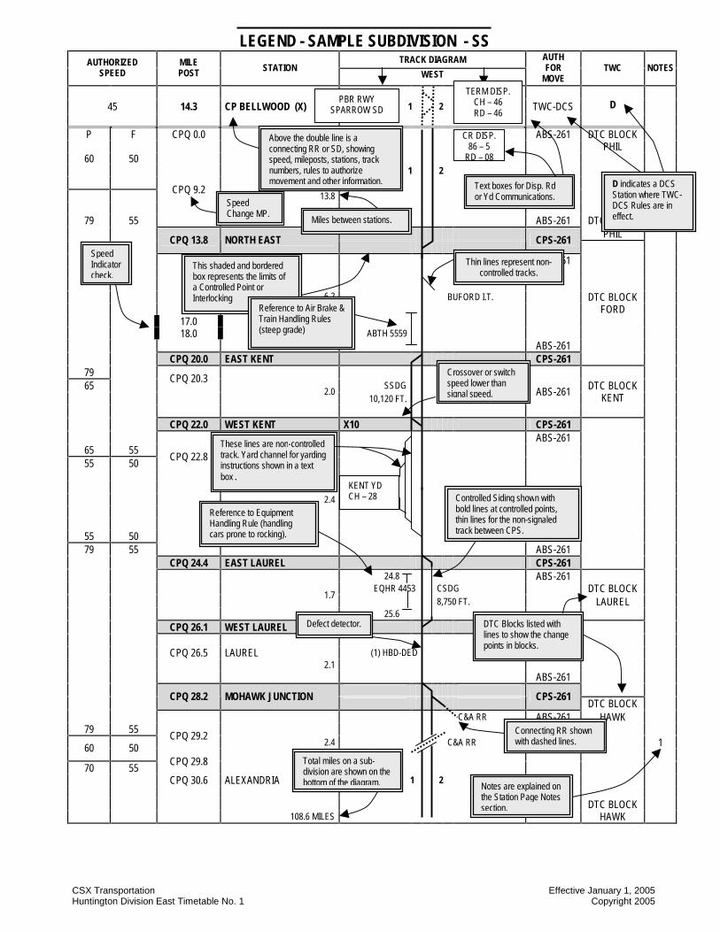
TIMETABLE LEGEND GENERAL
Unless otherwise indicated on subdivision pages, the train dispatcher controls all main tracks, sidings, Interlockings, controlled points and yard limits
STATION LISTING AND DIAGRAM PAGES
1 – HEADING
The subdivision is identified by name and by 2 letter identifier
2 – COLUMN HEADINGS AND LISTINGS A. AUTHORIZED SPEED The maximum speed permitted between mileposts listed may also include restrictions over road crossings or other defined locations. Where speeds differ between various classes of trains, they will be listed in separate columns. Abbreviations used are (P) – Passenger, (F) – Freight. Designations for other trains will be identified in Subdivision Special Instructions. Where speeds differ in multiple track territory, the speeds for individual tracks will be listed. Special speeds, such as over road crossings, will be shown in shaded blocks. B. MILEPOST The alpha-numeric milepost for the station or reference point. At locations to check speed indicators the mileposts will be listed without alpha prefixes and will be shown with a wide border. C. STATION The Controlled Point, Interlocking, Station or other reference point name. The miles between stations listed in bold letters will be shown on the right side of the column and total miles will be shown at end of diagram. D. TRACK DIAGRAM The timetable assigned direction from the first listing to the last is defined above the track diagram by arrows and direction. E. TWC – Track Warrant Control Rules TWC-DTC – Listing of TWC-DTC blocks for permanent or temporary use. TWC-DCS – Listing of TWC-DCS stations with the letter ‘D’ for permanent or temporary use as dispatching points.
F. AUTH FOR MOVE (AUTHORITY FOR MOVEMENT) The authority for movement rules applicable to the subdivision are listed below this box. G. NOTES Where station page information may need to be further defined, a note will refer to “STATION PAGE NOTES” listed at the end of the diagram.
3 – SYMBOLS USED IN THE DIAGRAM N – North S – South E – East W – West YL – Yard Limits NB – Northbound SB – Southbound EB – Eastbound WB – Westbound Milepost used for checking speed indicator accuracy will be shown without alpha prefixes and will be bordered like this: (P) Passenger Station CP Controlled Point (X) Interlocking (R) Remotely Controlled RT Running Track IT Industrial Track ss Spring Switch (A) Automatically Controlled ABS Automatic Block Signal Rules CPS Control Point Signal Rules TTB Thru-Truss Bridge CSS Cab Signal System Rules ATC Automatic Train Control Rules EQHR Equipment Handling Rules SDF Slide Detector Fence SDS Slide Detector Signal SDG Siding SSDG Signaled Siding CSDG Controlled Siding ABTH Air Brake and Train Handling Rules Communications text boxes show Dispatcher, Operator, Yardmaster or other station. AAR channel, call-in tone and where used, the number of "clicks" to call the station. If there is a separate road channel it be shown as "RD –" Defect Detectors (1) Type 1 (Equipment Handling Rules) (2) Type 2 (Equipment Handling Rules) AD Audible Detector DED Dragging Equipment Detector DEDAC Dragging Equipment Detector, Axle Counter HBD Hot Box Detector HCD High Car Detector HCDAC High Car Detector, Axle Counter HWD Hot Wheel Detector PDD Protruding Door Detector SWD Sliding Wheel Detector WID Wheel Impact Detector
CM DISP. 94 – 7
RD - 08
CSX Transportation Effective January 1, 2005 Huntington Division East Timetable No. 1 Copyright 2005
LEGEND - SAMPLE SUBDIVISION - SS TRACK DIAGRAM AUTHORIZED
SPEED MILE POST STATION
WEST
AUTH FOR
MOVE TWC NOTES
45 14.3 CP BELLWOOD (X) 1 2 TWC-DCS
D
P F CPQ 0.0 ABS-261 DTC BLOCK PHIL
60 50 1 2
CPQ 9.2 13.8
79 55 ABS-261 DTC BLOCK PHIL
CPQ 13.8 NORTH EAST
CPS-261
ABS-261 6.2 BUFORD I.T. DTC BLOCK FORD 17.0 18.0 ABTH 5559 ABS-261 CPQ 20.0 EAST KENT CPS-261
79 65
CPQ 20.3 SSDG
2.0
10,120 FT. ABS-261 DTC BLOCK
KENT CPQ 22.0 WEST KENT X10 CPS-261 ABS-261
65 55 55 50
CPQ 22.8
2.4
55 50 79 55
ABS-261
CPQ 24.4 EAST LAUREL CPS-261 24.8 ABS-261 EQHR 4453 CSDG DTC BLOCK
1.7 8,750 FT.
LAUREL
25.6 CPQ 26.1 WEST LAUREL CPQ 26.5 LAUREL (1) HBD-DED 2.1 ABS-261
CPQ 28.2 MOHAWK JUNCTION
CPS-261 DTC BLOCK
C&A RR ABS-261 HAWK 79 55
CPQ 29.2 2.4 C&A RR 1 60 50
70 55
CPQ 29.8
CPQ 30.6 ALEXANDRIA 1 2 DTC BLOCK 108.6 MILES HAWK
TERM DISP. CH – 46 RD – 46
PBR RWY SPARROW SD
CR DISP. 86 – 5
RD – 08
Above the double line is a connecting RR or SD, showing speed, mileposts, stations, track numbers, rules to authorize movement and other information. Text boxes for Disp. Rd
or Yd Communications. Speed
Change MP. Miles between stations.
This shaded and bordered box represents the limits of a Controlled Point or Interlocking
Thin lines represent non- controlled tracks.
Speed Indicator check.
These lines are non-controlled track. Yard channel for yarding instructions shown in a text box.
KENT YD CH – 28
Crossover or switch speed lower than signal speed.
Controlled Siding shown with bold lines at controlled points, thin lines for the non-signaled track between CPS.
Defect detector.
Connecting RR shown with dashed lines.
DTC Blocks listed with lines to show the change points in blocks.
Total miles on a sub-division are shown on the bottom of the diagram. Notes are explained on
the Station Page Notes section.
D indicates a DCS Station where TWC-DCS Rules are in effect.
Reference to Equipment Handling Rule (handling cars prone to rocking).
Reference to Air Brake & Train Handling Rules (steep grade)

CSX Transportation Effective January 1, 2005 Huntington Division East Timetable No. 1 Copyright 2005
HUNTINGTON EAST DIVISION 935 7th. Avenue
Huntington WV 25701
G. M. Williams III Division Manager
T. W. Swisher Assistant Division Manager
J. F. Ward Senior Road Foreman of Engines
S.F. Santer Manager Safety and Operating Practices
R.D. Toms Mechanical Superintendent
K.L. Wilson Division Engineer
Location and Name Title Location and Name Title Location and Name Title Brooklyn Jct., WV Fostoria, OH Marysville, OH R.L. Hanson Trainmaster D. C. Johnson Roadmaster D. A. Schmidt Terminal Manager D. E. Moorman Manager Signals T. M. Curry Trainmaster Terminal Buckhannon, WV J. D. Schwartz Trainmaster Terminal A. L. Sharps Roadmaster Glasgow, VA J. D. Mallett Roadmaster F. M. Withers Asst. Roadmaster D. R. Hale Roadmaster Chillicothe, OH Glen Morgan, WV Maysville, KY D. R. Lindamood Roadmaster L. E. Wynn Engineer Track J. E. Stafford Roadmaster J. E. Johnson Asst. Roadmaster Clarksburg, WV R. I. Hunt Roadmaster Grafton, WV Newell, PA R. T. Workman Trainmaster F. R. Mazurik Terminal Manager Clifton Forge, VA J. P. Harr, Jr. Trainmaster D.R. Mancuso Coal Coordinator D. L. Hensley Superintendent L. O. R. K. W. Freeze Road Foreman of Engines G. J. Tylka Coal Coordinator E. W. Knick Trainmaster G. A. Raupach Manager Bridges M.J. Yates Coal Coordinator M. L. Persinger Trainmaster J. W. Ketchem Manager Signals D. R. Giusti Coal Coordinator Vacant Terminal Trainmaster A. M. Mooney Coal Coordinator Vacant Asst. Trainmaster Hinton, WV C. H. Mack Road Foreman of Engines J. M. Angell Trainmaster Newport News, VA Vacant General Foreman G. L. Flanagan Trainmaster R. L. McClure Trainmaster K. W. Gunter Roadmaster A. D. Nicolls Road Foreman of Engines C. G. Weeks Trainmaster R. S. Perry Manager Signals K. O. Faulkner General Foreman Huntington, WV Columbus, OH Vacant Superintendent L. O. R. Parkersburg, WV Vacant Terminal Manager W. S. Jessee Manager Coal Operations Vacant Trainmaster N. M. Male Trainmaster Terminal D. F. Ward Manager Coal Operations R. W. Queen Trainmaster M. C. Kennaw Trainmaster Terminal B. D. Totty Manager Coal Operations C. R. Henderson Road Foreman of Engines R. S. Viti Terminal Trainmaster R. J. Hall Manager Coal Operations A. L. Sharps Asst. Roadmaster S. M. Vallance Trainmaster Terminal R. D. Logan Manager Coal Operations D. A. Stafford Bridge Inspector D. L. Smith Trainmaster (STD) L. J. Lyninger Coal Coordinator D. E. Wright Trainmaster (temp) R. D. Sheffey Terminal Trainmaster J. O. Polock Trainmaster – Van Yard B. S. Lusk Terminal Trainmaster Peach Creek, WV T. R. Gilliam Road Foreman of Engines L. W. Lyninger Senior General Foreman R. R. Ramey Trainmaster K. D. Huffman Asst. General Foreman T. R. Lester Roadmaster B. G. Brooks Roadmaster D. J. Dean Engineer Track D. B. Caldwell Asst. Roadmaster H. P. Simmons Roadmaster T. D. Ison Engineer Signal Construction Prince, WV T. R. Jones Asst. Roadmaster J. E. Hindes Manager Signals E. H. Felton Roadmaster W. Morris Engineer Track J. A. Buckley Engineer Administration Ravenswood, WV Cowen, WV R. C. Kaiser, Jr. Manager Facilities R. D. Vanpelt Roadmaster F. M. Withers Asst. Roadmaster R. J. Wall Manager Bridges M. F. Smith Manager Bridges Richmond, VA Cumberland, MD M. K. Robey Trainmaster R. C. Pollock Trainmaster K. L. Kelsey Trainmaster S. R. Vinci Trainmaster Jacksonville, FL K. D. Jackson Trainmaster R. A. Ford Road Foreman of Engines W. J. Estep Chief Dispatcher J. S. Baker Road Foreman of Engines C. W. Kersten, Jr. Chief Dispatcher N. R. Beard Manager Signals Danville, WV W. K. Critzer Roadmaster M. L. McCauley Trainmaster Marietta, OH A. R. Perry Trainmaster J. D. Conley Roadmaster S. Shadd Jr. Road Foreman of Engines M. E. Dier Roadmaster Elk Run Jct., WV J. W. Beckett Trainmaster P. R. Morris Trainmaster
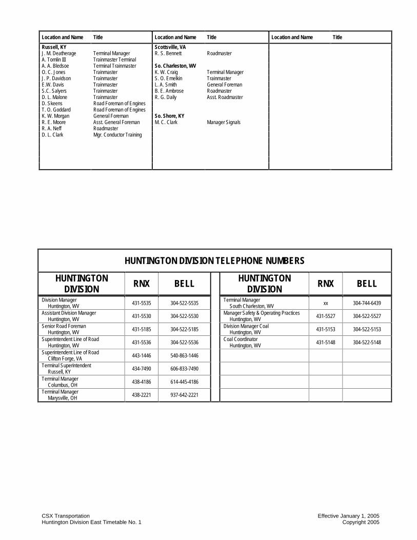
CSX Transportation Effective January 1, 2005 Huntington Division East Timetable No. 1 Copyright 2005
Location and Name Title Location and Name Title Location and Name Title
Russell, KY Scottsville, VA J. M. Deatherage Terminal Manager R. S. Bennett Roadmaster A. Tomlin III Trainmaster Terminal A. A. Bledsoe Terminal Trainmaster So. Charleston, WV O. C. Jones Trainmaster K. W. Craig Terminal Manager J. P. Davidson Trainmaster S. O. Emelkin Trainmaster E.W. Davis Trainmaster L. A. Smith General Foreman S.C. Salyers Trainmaster B. E. Ambrose Roadmaster D. L. Malone Trainmaster R. G. Daily Asst. Roadmaster D. Skeens Road Foreman of Engines T. O. Goddard Road Foreman of Engines K. W. Morgan General Foreman So. Shore, KY R. E. Moore Asst. General Foreman M. C. Clark Manager Signals R. A. Neff Roadmaster D. L. Clark Mgr. Conductor Training
HUNTINGTON DIVISION TELEPHONE NUMBERS
HUNTINGTON DIVISION RNX BELL HUNTINGTON
DIVISION RNX BELL
Division Manager Huntington, WV 431-5535 304-522-5535
Terminal Manager South Charleston, WV xx 304-744-6439
Assistant Division Manager Huntington, WV 431-5530 304-522-5530
Manager Safety & Operating Practices Huntington, WV 431-5527 304-522-5527
Senior Road Foreman Huntington, WV 431-5185 304-522-5185
Division Manager Coal Huntington, WV 431-5153 304-522-5153
Superintendent Line of Road Huntington, WV 431-5536 304-522-5536
Coal Coordinator Huntington, WV 431-5148 304-522-5148
Superintendent Line of Road Clifton Forge, VA 443-1446 540-863-1446
Terminal Superintendent Russell, KY 434-7490 606-833-7490
Terminal Manager Columbus, OH
438-4186 614-445-4186
Terminal Manager Marysville, OH 438-2221 937-642-2221
CSX Transportation Effective January 1, 2005 Huntington Division East Timetable No. 1 Copyright 2005
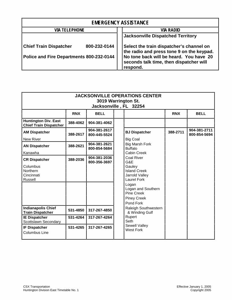
EMERGENCY ASSISTANCE VIA TELEPHONE VIA RADIO
Chief Train Dispatcher 800-232-0144 Police and Fire Departments 800-232-0144
Jacksonville Dispatched Territory Select the train dispatcher’s channel on the radio and press tone 9 on the keypad. No tone back will be heard. You have 20 seconds talk time, then dispatcher will respond.
JACKSONVILLE OPERATIONS CENTER 3019 Warrington St.
Jacksonville , FL 32254
RNX BELL
RNX BELL
Huntington Div. East Chief Train Dispatcher
388-4062 904-381-4062
904-381-2617 AM Dispatcher 800-445-5524
BJ Dispatcher 388-2711 904-381-2711 800-854-5694
New River 388-2617
Big Coal
904-381-2621 Big Marsh Fork AN Dispatcher 388-2621 800-854-5684 Buffalo
Kanawha Cabin Creek 904-381-2036 Coal River CR Dispatcher 388-2036 800-356-3697 G&E
Columbus Gauley Northern Island Creek Cincinnati Jarrold Valley Russell Laurel Fork Logan Logan and Southern Pine Creek
Piney Creek
Pond Fork
Indianapolis Chief Train Dispatcher 531-4850 317-267-4850
IE Dispatcher 531-4264 317-267-4264 Scottslawn Secondary
IF Dispatcher 531-4265 317-267-4265
Columbus Line
Raleigh Southwestern & Winding Gulf Rupert Seth Sewell Valley West Fork

CSX Transportation Effective January 1, 2005 Huntington Division East Timetable No. 1 Copyright 2005
JACKSONVILLE OPERATIONS CENTER 3019 Warrington St.
Jacksonville , FL 32254
RNX BELL
RNX BELL
Huntington Div. East Chief Train Dispatcher
388-2782 904-381-2782
AM Dispatcher 388-2618 904-381-2618 800-445-5524
CJ Dispatcher 388-2681 904-381-2681 800-854-5689
Alleghany North Mountain Piedmont Washington
Bridgeport Marietta Ohio River Pomeroy Short Line AL Dispatcher 388-5183 904-381-5183
800-854-5696 James River Peninsula Rivanna
CI Dispatcher 388-2651 904-381-2651 800-854-5690
Cowen Fairmont Georges Creek Kingwood Mountain Pickens Stony River Thomas
CSX Transportation Effective January 1, 2005 Huntington Division East Timetable No. 1 Copyright 2005
NOTES
NOTES

CSX Transportation ALLEGHANY SUBDIVISION - AG Effective January 1, 2005 Huntington Division East Timetable No. 1 © Copyright 2005
ALLEGHANY SUBDIVISION - AG TRACK DIAGRAM AUTHORIZED
SPEED MILE POST STATION
WEST
AUTH FOR
MOVE TWC NOTES
P F ABS-261 North Mtn. (193)
60 40
James River BBRR JAMES RIVER
ABS-261 25 25
(193)
P F 1=WB 2=EB
35 25 25 ABS-261
(193)
CA 276.0 JD CABIN
CPS-261 (193)
35
ABS-261
YL
1
0.8 (193) CPS-261
UN
DER
10,
000
TON
S
BETW
EEN
10,
000
AN
D
14,0
00 T
ON
S
OVE
R 1
4,00
0 TO
NS
CA 276.8 CLIFTON FORGE (193)
35 35 25 25 1 2
CA 277.1 0.9
20 20 20 20
ABS-261 (193)
CA 277.8 EAST R.A.F.
CPS-261 (193)
10 10 10 10 ABS-261
(193)
CA 277.9 WEST R.A.F.
CPS-261 (193)
ABS-261 20 20 20 20 0.7 (193)
25 25 CA 278.4 JACKSON RIVER
BRIDGE CPS-261
(193) CA 278.5 2.4
TTB ABS-261 (193)
NO
. 1
50
NO
. 2
30
NO
. 1
40
NO
. 2
30
25 25
YL 3 40 40 35
CA 280.8 LOW MOOR
CPS-261 (193)
50
60 CA 281.8
2.3 ABS-261
DTC BLOCK MOOR
CA 283.0
60 T/O
CA 283.1
40 60
CA 283.2 MP 283
CPS-261
ABS-261
60 40 40 40 35 35
CA 283.9
DTC BLOCK
40 35 35 5.0 MALLOW 50 40 40
CA 284.6
285 286 CA 287.1 (2) HBD-DED-AD
50 CA 287.3
40
40 40 35 ABS-261
1 2 JAMES RIVER SD
AM DISP. 14-4
RD 08
AL DISP. 14-3
RD 08
AM DISP. 14-5
RD 08

CSX Transportation ALLEGHANY SUBDIVISION - AG Effective January 1, 2005 Huntington Division East Timetable No. 1 © Copyright 2005
ALLEGHANY SUBDIVISION - AG TRACK DIAGRAM AUTHORIZED
SPEED MILE POST STATION
WEST
AUTH FOR
MOVE TWC NOTES
P F
UN
DER
10,
000
TON
S Be
twee
n 10
,000
an
d 14
,000
tons
O
VER
\14,
000
TON
S
ABS-261 DTC BLOCK
MALLOW 40 40 40 35 CA 288.0 (193) YL
50
CA 288.1 MP 288
CPS-261 (193)
ABS-261
CA 288.4 1 2 (193)
50 40 40 1.3 35 35 35
CA 289.1
ABS-261 (193)
CA 289.4 MP 289
CPS-261 (193)
CA 289.8 1.5
CA 290.3 ABS-261
(193)
35 35 35 50 40 40
CA 290.5 COVINGTON
CPS-261 (193)
2, 4
CA 291.0
CA 291.4 291.4 SSDG 8,800 FT ABS-261 5.8 (193) CA 291.9
CA 292.3 BS CABIN
CPS-261
(193) 2, 4
ABS-261 (193) YL
CA 293.0 ABS-261
CA 294.3 CA 294.4
MUD TUNNEL CA 295.2 EAS CALLAHAN
50 2.9 ABTH 5559 60 45
CA 297.6 DTC BLOCK
CALLA
NO
. 1
NO
. 2
60 45
50 CA 297.8
CA 298.0 ABS-261
50
CA 298.1 OX CABIN
CPS-261
40 DTC BLOCK WATTS
CA 298.2
298.2 ABS-261 50
40 40 35
POTTS CREEK IT
COVINGTON IT TTB

CSX Transportation ALLEGHANY SUBDIVISION - AG Effective January 1, 2005 Huntington Division East Timetable No. 1 © Copyright 2005
ALLEGHANY SUBDIVISION – AG TRACK DIAGRAM AUTHORIZED
SPEED MILE POST STATION
WEST
AUTH FOR
MOVE TWC NOTES
P F
UN
DER
10,
000
TON
S Be
twee
n 10
,000
an
d 14
,000
tons
O
VER
14,
000
TON
S
50 40 40 35 298.2 ABS-261
50 7.2 40
CA 299.2
40 45
CA 299.8
CA 300.1 EAS BACKBONE DTC BLOCK WATTS CA 301.1 CA 301.2 MOORES TUNNEL CA 301.4 CA 301.5 LAKES TUNNEL CA 302.5 ABTH 5559 CA 302.6 KELLEYS TUNNEL
45 40 40 35 35 35
CA 302.7
CA 303.0 JERRYS RUN
CA 304.4 CA 305.2 LEWIS TUNNEL
CA 305.4
DTC BLOCK LEWIS
35 35 35 35 305.4 ABS-261

CSX Transportation ALLEGHANY SUBDIVISION - AG Effective January 1, 2005 Huntington Division East Timetable No. 1 © Copyright 2005
ALLEGHANY SUBDIVISION - AG TRACK DIAGRAM AUTHORIZED
SPEED MILE POST STATION
WEST
AUTH FOR
MOVE TWC NOTES
P F
UN
DER
10
,000
TO
NS
BETW
EEN
10
,000
AN
D
14,0
00
TON
S
OVE
R
14,0
00
TON
S
305.4 ABS-261
DTC BLOCK WATTS 35 35 35 35 CA 305.4
ABTH 5559 305.5
CA 305.5 EAST ALLEGHANY
CPS-261
35 35 35 1 2 ABS-261 DTC BLOCK 45 45 40 40
CA 305.8 LEWIS
CA 306.6 2.7
CA 306.7 3 CA 306.9 ALLEGHANY TUNNEL
No.
2
CA 307.0 30 40 30 40 30 35 30
CA 307.3 VA / WV STATE LINE CA 307.7 N
o. 2
No.
1
No.
2
No.
1
No.
2
No.
1
No.
2
ABS-261
No.
1
CA 308.0 TUCKAHOE CPS-261 DTC BLOCK
SUGAR
ABS-261 CA 308.3 CA 308.7
SDF SDF
45
50
CA 310.5
3.9
No.
1
CA 311.4
50 55
CA 311.6
ABS-261
CA 311.7 EAST END WHITE SULPHUR
CPS-261
CA 311.8 (2) HBD-DED-AC-AD
ABS-261
CA 311.9 WHITE SULPHUR SPRINGS
CPS-261
ABS-261 DTC BLOCK WHITE
CA 312.4 WS CABIN
CPS-261
No.
1
ABS-261 55
CA 315.3
45
No.
2
No.
1
No.
2
No.
1
No.
2
No.
1
No
2
45 30 40 30 40 30 35 30
ABS-261

CSX Transportation ALLEGHANY SUBDIVISION - AG Effective January 1, 2005 Huntington Division East Timetable No. 1 © Copyright 2005
ALLEGHANY SUBDIVISION - AG TRACK DIAGRAM AUTHORIZED
SPEED MILE POST STATION
WEST
AUTH FOR
MOVE TWC NOTES
P F
UN
DER
10,
000
TON
S
BETW
EEN
10
,000
AN
D
14,0
00 T
ON
S
OVE
R 1
4,00
0 TO
NS
45 30 40 30 40 30 35 30 ABS-261 35 30 35 30 35 30 35 30
CA 315.6 7.6
1 2
No.
1 T
rack
No.
2 T
rack
No.
1 T
rack
No.
1 T
rack
No
2 Tr
ack
No.
1 T
rack
No
2 Tr
ack
35 35 35 DTC BLOCK
No.
2 T
rack
CA 317.6 WHITE 45
40 40
CA 318.8 SDF CA 319.4
SDF
CA 319.5
No.
1 T
rack
No.
2 T
rack
No.
1 T
rack
No.
2 T
rack
No.
1 T
rack
No.
2 T
rack
No.
1 T
rack
No.
2 T
rack
ABS-261 45 30 40 30 40 30 35 30
60 40 40 35 CA 320.0 WHITCOMB
CPS-261
2 1.4
ABS-261
CA 321.4 BROWNS MILL CPS-261 ABS-261
60 45 50 CA 322.1
DTC BLOCK
No.
1
45
BROWN
CA322.4
50
SSDG 12,200 FT.
No.
1
No.
2
2.6
50 50
60 CA 323.1
CA 323.9
ABS-261 DTC BLOCK
60 ROCK 40
CA 324.0 WR CABIN
CPS-261
ABS-261
40 40 40 35
CSX Transportation ALLEGHANY SUBDIVISION - AG Effective January 1, 2005 Huntington Division East Timetable No. 1 © Copyright 2005
ALLEGHANY SUBDIVISION - AG TRACK DIAGRAM AUTHORIZED
SPEED MILE POST STATION
WEST
AUTH FOR
MOVE TWC NOTES
P F
UN
DER
10,
000
TON
S
BETW
EEN
10
,000
AN
D
14,0
00 T
ON
S
OVE
R 1
4,00
0 TO
NS
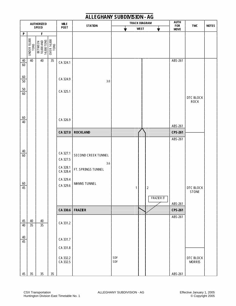
40 40 40 35 ABS-261 60
CA 324.1
60 50
CA 324.9 3.0
50 60
CA 325.1
DTC BLOCK ROCK
60 40
CA 326.9
ABS-261
CA 327.0 ROCKLAND
CPS-261
ABS-261
40 60
CA 327.1 CA 327.5
SECOND CREEK TUNNEL
3.6 CA 328.1 CA 328.4
FT. SPRINGS TUNNEL CA 329.4
60 45
CA 329.6 MANNS TUNNEL 1 2 DTC BLOCK
STONE ABS-261
CA 330.6 FRAZIER
CPS-261
ABS-261 45 40 40 40 35 35
CA 331.2
40 45
CA 331.7
CA 331.8
CA 332.2 SDF DTC BLOCK CA 332.5
SDF MORRIS
45 35 35 35 ABS-261
FRAZIER IT

CSX Transportation ALLEGHANY SUBDIVISION - AG Effective January 1, 2005 Huntington Division East Timetable No. 1 © Copyright 2005
ALLEGHANY SUBDIVISION - AG TRACK DIAGRAM AUTHORIZED
SPEED MILE POST STATION
WEST
AUTH FOR
MOVE TWC NOTES
P F
UN
DER
10,
000
TON
S Be
twee
n 10
,000
an
d 14
,000
tons
O
VER
14,
000
TON
S
45 35 35 35 ABS-261 CA 333.1 SDF
45 40
CA 333.4
SDF
DTC BLOCK
40 MORRIS 45
CA 334.4
1 2 45 35
CA 335.3
5.7
CA 335.5
ABS-261
CA 336.3 ALDERSON
CPS-261
ABS-261
35 45
CA 336.6 DTC BLOCK
CA 336.7 (1) HBD-DED-AC PRISON 5.0
45 35 35 60 40 40
CA 337.8
3 3
CA 339.5
5 5 35 CA 339.7
40
35
35
DTC BLOCK RIFFE
No.
1
No.
2
No.
1
No.
2
No.
1
No.
2
No.
1
No.
2
CA 340.2 6
0 40
40
35
40
35
35
35
ABS-261
CSX Transportation ALLEGHANY SUBDIVISION - AG Effective January 1, 2005 Huntington Division East Timetable No. 1 © Copyright 2005
ALLEGHANY SUBDIVISION - AG TRACK DIAGRAM AUTHORIZED
SPEED MILE POST STATION
WEST
AUTH FOR
MOVE TWC NOTES
P F
UN
DER
10,
000
TON
S
BETW
EEN
10
,000
AN
D
14,0
00 T
ON
S
OVE
R 1
4,00
0 TO
NS
60 40 40 35 40 35 35 35 1 2 ABS-261 N
o. 1
Tra
ck
No.
2 T
rack
No.
2 T
rack
No.
2 T
rack
No.
1 T
rack
No.
2 T
rack
40
No.
1 T
rack
35
No.
1 T
rack
35 35
CA 341.1 25 25 25 25
ABS-261 RIFFE WEIGH CA 341.3
IN MOTION SCALE CPS-261
No.
2
No.
2
No.
2
No.
2
ABS-261
25 25 25
25
DTC BLOCK RIFFE N
o. 1
Tra
ck
CA 341.5
60 50 40 40 35
50 CA 341.6
CA 341.8 SDF N
o. 1
No.
2
No.
1
No.
2
No.
1
No.
2
50 40 40 40 40 35 35
60 40 40 35 CA 342.0
1.5
CA 342.1 SDF
60 ABS-261
T/O PASSENGER ONLY 40
CA 342.8 PENCE SPRINGS TO=40
CPS-261
60 ABS-261 345 6.7 WID 5 346 CA 347.3 TALCOTT
60 SPUR DTC BLOCK 40
CA 348.1 TALCOTT CA 349.2
BIG BEND TUNNEL
ABS-261
CA 349.5 HILLDALE
CPS-261
ABS-261
CA 349.7
1 2 DTC BLOCK BIG BEN
40 40 40 40 35 ABS-261
CSX Transportation ALLEGHANY SUBDIVISION - AG Effective January 1, 2005 Huntington Division East Timetable No. 1 © Copyright 2005
ALLEGHANY SUBDIVISION - AG TRACK DIAGRAM AUTHORIZED
SPEED MILE POST STATION
WEST
AUTH FOR
MOVE TWC NOTES
P F
UN
DER
10,
000
TON
S
BETW
EEN
10
,000
AN
D
14,0
00 T
ON
S
OVE
R 1
4,00
0 TO
NS
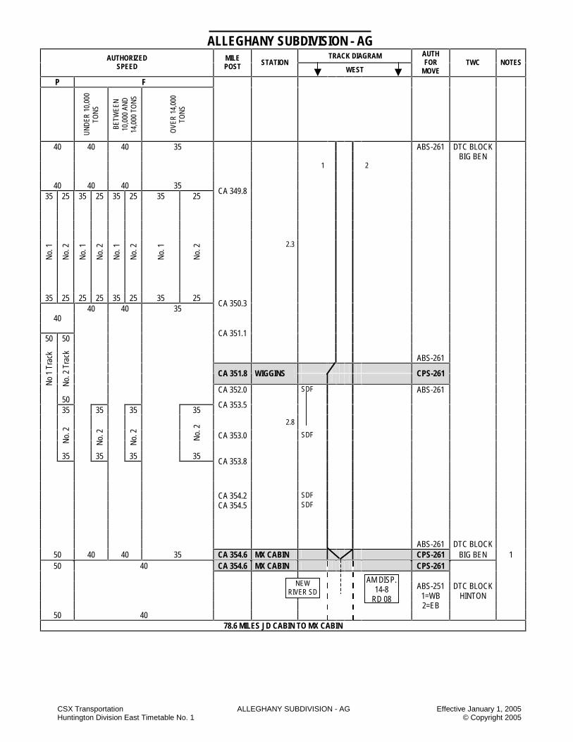
40 40 40 35 ABS-261 DTC BLOCK BIG BEN 1 2
40 40 40 35 CA 349.8
35 25 35 25 35 25 35 25
No.
1
No.
2
No.
1
No.
2
No.
1
No.
2
No.
1
No.
2
2.3
35 25 25 25 35 25 35 25 40 40 35
CA 350.3
40
50 50 CA 351.1
ABS-261
CA 351.8 WIGGINS
CPS-261 N
o 1
Trac
k
No.
2 T
rack
CA 352.0 SDF ABS-261 50 35 35 35 35
CA 353.5
2.8
CA 353.0 SDF
No.
2
No.
2
No.
2
No.
2
35 35 35 35
CA 353.8
CA 354.2 SDF CA 354.5 SDF ABS-261 DTC BLOCK
50 40 40 35 CA 354.6 MX CABIN CPS-261 BIG BEN 1 CA 354.6 MX CABIN CPS-261
50 40
ABS-251 DTC BLOCK
1=WB HINTON 2=EB
50 40 78.6 MILES JD CABIN TO MX CABIN
NEW RIVER SD
AM DISP. 14-8
RD 08

CSX Transportation ALLEGHANY SUBDIVISION - AG Effective January 1, 2005 Huntington Division East Timetable No. 1 © Copyright 2005
STATION PAGE NOTES
NOTE 1: All Signals are CSX Signal Rules C1281 – C1298. NOTE 2: BS Cabin and Ronceverte are signaled sidings. NOTE 3: Between CA 280.8 and CA 306.7 eastbound freight trains are restricted to an authorized speed of 35 MPH. NOTE 4: Authorized speed on BS center siding is 10 MPH. NOTE 5: Refer to Alleghany Sub Special Instruction regarding wheel impact detectors (WID), Page 14.

CSX Transportation ALLEGHANY SUBDIVISION – AG Effective January 1, 2005 Huntington Division East Timetable No. 1 © Copyright 2005
ALLEGHANY SUBDIVISION SPECIAL INSTRUCTIONS
1. INSTRUCTIONS RELATING TO OPERATING RULES
Excepted Tracks The following tracks are designated as excepted track:
All tracks within the confines of the locomotive shop and old servicing facilities at Clifton Forge. Engine Bell
Clifton Forge – In addition to the requirements of Rule 13, the engine bell must be rung before entering and while passing through the Locomotive Fueling Facility between CA 277.6 and CA 277.7. Yard Limits Clifton Forge Yard 1. Eastbound freight trains arriving must contact the
yardmaster upon passing MP CA 290.0 for instructions.
Westbound freight trains arriving must contact the yardmaster before passing JD Cabin, MP CA 276.1 for instructions. Eastbound and westbound trains at the above locations must convey the following information to the yardmaster: The direction locomotives are headed and any problems with locomotives that would prohibit their use. Eastbound and westbound freight trains must obtain instructions from the yardmaster before departing. All crews leaving trains unattended on main lines at Clifton Forge fueling facility will notify AM dispatcher that they have stopped and are off the train. This must be done prior to being relieved. All trains and engines must contact RAF fueling facility employee for instruction prior to arriving, departing or passing through the RAF fueling facility.
2. Hinton – All eastbound trains departing Hinton must
advise the AM train dispatcher of the direction locomotives in the consist are headed and if there are any problems with the locomotives that would prohibit their use.
Highway Crossings at Grade Howell Street CA 335.7 – In order to prevent the crossing signals from activating, westbound trains that STOP at the WAS Alderson must stay east of the white post located at CA 335.7 – 500 feet east of Monroe Street. Hand Brakes - Cars
The following chart applies to cars and trains left unattended.
Location Loaded Minimum
Empty Minimum
Comments
Covington CL 1 and CL 2
set off 10% 10%
Covington Yard 1 through 12 3 HB 3 HB
Covington Yard 13 through 19 2 HB 2 HB
Applied on east-end
Clifton Forge
10%
4 HB
Head-end westbound
empty trains
Use of Specified Tracks
Clifton Forge Yard
Thoroughfare – Westbound movements must not be made except on instructions from the yardmaster. After ascertaining that the track is clear, westbound movement may be allowed when the yardmaster is advised by the train dispatcher that the power-operated switches at Low Moor have been blocked in position to prevent entrance to the receiving yard. Middle Yard – Hand brakes must not be released on head end of trains in the new classification yard until the engine is attached and air brakes applied. Selma Switching Lead – Westbound movements must not be made on the Selma switching lead without instructions of yardmaster. Shop tracks -- Cars will not be shoved west of STOP signs located west of the concrete pad on No. 2 and No. 3 shop tracks. Covington Yard Yardmaster’s instructions must be obtained before occupying yard tracks at Covington. Switching procedures – All of the tracks that will be used for switching must be physically checked for the following:
Tracks 13 through 19 must have a minimum of two (2) hand brakes applied on the east-end of the track. All other tracks must have a minimum of three (3) hand brakes applied on the east-end of the track. Cars left in Tracks 13 through 18 must have a minimum of one (1) car length of space between the east-end of the east cars and the end of the track. All crews must comply with Operating Rule 103-A. Cars must not be left to foul other tracks. Cars must be shoved to rest in Tracks 13 through 19. Cars must not be dropped or kicked.

CSX Transportation ALLEGHANY SUBDIVISION – AG Effective January 1, 2005 Huntington Division East Timetable No. 1 © Copyright 2005
Crews must take into consideration the following when switching:
The amount of available track space before switching, dropping or kicking cars. Load/empty ratio of the cars in the track Are hand brakes applied on loaded or empty cars? Frequently, hand brakes applied on empty cars will slide when the cars are moved. A sliding wheel offers very little retarding force. Cars must not be moved if the wheels are sliding. Sliding wheels contribute to wheel defects and failures. If a wheel is seen to be sliding, STOP the movement. After correcting the problem, then proceed with the movement. What is the tonnage of the cars being dropped or kicked? Are there sufficient hand brakes applied on the cars to control the movement? Loaded tank cars will move because of sloshing of the contents of the car. If there is any doubt that the cars will be shoved out of the clear or foul another track or that the cars will be shoved off the end of the track; don’t take a chance.
A. Switching 1. Operating Rule 103-A is modified by the addition of the
following to the existing rule:
No more than three cars at a time will be cut off in motion when switching in Covington Yard. All cuts over three cars will be shoved to rest.”
2. Eastern Code, Hazardous Material Rules, effective October 1, 2000, section 5, switching chart restrictions 2 and 3 remain as written and are not modified by this bulletin.
B. Hand-Operated Switches 1. Operating Rule 104-C, first paragraph, is modified as
follows:
“Before using switches in Covington Yard, employees must physically check each switch prior to their movement over that switch to ascertain that:
1. The route is lined for their movement 2. The switch points fit properly, and 3. The lever is secured.
2. All other portions of Operating Rule 104-C remain in
effect and unchanged. Covington – Westvaco All tracks – Train crews must turn on warning lights and/or bells before entering the track. Upon completion of switching lights and/or bells must be turned off.
Coal facility – Trains setting off or picking up at this facility will be governed as follows: 1. Trains must use No. 1 main track for setting off or
picking up. 2. Trains must secure instructions from the Clifton Forge
yardmaster and permission of the train dispatcher before occupying tracks of Westvaco Coal Facility.
3. Eastward trains setting off loads – No. 1 coal track
must be filled first, through to No. 6 coal track. The last cars set off in No. 6 coal track must be shoved toward the locomotive shed on the west end and allowed to hang down the lead on the east end to clear the dumper.
4. Westward trains picking up empties – When doubling
tracks, start with No. 6 coal track and make the last double to No. 1 coal track. No. 1 coal track will hang down the lead toward the dumper.
Snowflake – Loaded tracks must not be used as a thoroughfare to Snowflake Hollow tracks. Signals Not in Conformity with Signal Aspects and Indications Rules Riffe Scales CA 341.3 – Trains will be weighed unless signal indication indicates otherwise. The EAS located on the ground mast at the west end of the scale track and the WAS located on the cantilever mast at the east end of the scale track are arranged to display the following aspect and indication when switches are lined for movement on the scale track and the train dispatcher station has positioned the governing signal: Name Weigh Aspect Two red lights, one above the other, with
illuminated letter W in between and slightly to the right.
Indication Proceed in accordance with weighing
instructions and approach next signal prepared to comply with signal indication, not exceeding controlled speed.
The following aspect could be displayed at the EAS at Pence Springs (CA 342.8) and the westbound intermediate signal 3405 on No. 2 track (CA 340.5).
Name Approach weigh.
Aspect Westbound signal – A yellow light above number plate with an illuminated letter W in between and slightly to the right.
Eastbound absolute signal – A yellow light above a red light with illuminated letter W in between and slightly to the right.
Indication Proceed prepared to comply with weighing instructions at the next signal. Trains exceeding medium speed must at once reduce to that speed.
The following aspect could be displayed at the EAS at Pence Springs (CA 342.8)
CSX Transportation ALLEGHANY SUBDIVISION – AG Effective January 1, 2005 Huntington Division East Timetable No. 1 © Copyright 2005
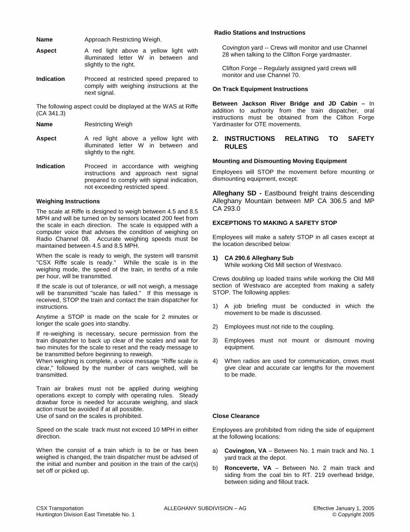
Name Approach Restricting Weigh.
Aspect A red light above a yellow light with illuminated letter W in between and slightly to the right.
Indication Proceed at restricted speed prepared to
comply with weighing instructions at the next signal.
The following aspect could be displayed at the WAS at Riffe (CA 341.3)
Name Restricting Weigh Aspect A red light above a yellow light with
illuminated letter W in between and slightly to the right.
Indication Proceed in accordance with weighing
instructions and approach next signal prepared to comply with signal indication, not exceeding restricted speed.
Weighing Instructions
The scale at Riffe is designed to weigh between 4.5 and 8.5 MPH and will be turned on by sensors located 200 feet from the scale in each direction. The scale is equipped with a computer voice that advises the condition of weighing on Radio Channel 08. Accurate weighing speeds must be maintained between 4.5 and 8.5 MPH.
When the scale is ready to weigh, the system will transmit "CSX Riffe scale is ready." While the scale is in the weighing mode, the speed of the train, in tenths of a mile per hour, will be transmitted.
If the scale is out of tolerance, or will not weigh, a message will be transmitted "scale has failed." If this message is received, STOP the train and contact the train dispatcher for instructions.
Anytime a STOP is made on the scale for 2 minutes or longer the scale goes into standby.
If re-weighing is necessary, secure permission from the train dispatcher to back up clear of the scales and wait for two minutes for the scale to reset and the ready message to be transmitted before beginning to reweigh. When weighing is complete, a voice message "Riffe scale is clear," followed by the number of cars weighed, will be transmitted. Train air brakes must not be applied during weighing operations except to comply with operating rules. Steady drawbar force is needed for accurate weighing, and slack action must be avoided if at all possible. Use of sand on the scales is prohibited. Speed on the scale track must not exceed 10 MPH in either direction. When the consist of a train which is to be or has been weighed is changed, the train dispatcher must be advised of the initial and number and position in the train of the car(s) set off or picked up.
Radio Stations and Instructions
Covington yard -- Crews will monitor and use Channel 28 when talking to the Clifton Forge yardmaster. Clifton Forge – Regularly assigned yard crews will monitor and use Channel 70.
On Track Equipment Instructions Between Jackson River Bridge and JD Cabin – In addition to authority from the train dispatcher, oral instructions must be obtained from the Clifton Forge Yardmaster for OTE movements. 2. INSTRUCTIONS RELATING TO SAFETY
RULES Mounting and Dismounting Moving Equipment
Employees will STOP the movement before mounting or dismounting equipment, except: Alleghany SD - Eastbound freight trains descending Alleghany Mountain between MP CA 306.5 and MP CA 293.0
EXCEPTIONS TO MAKING A SAFETY STOP Employees will make a safety STOP in all cases except at the location described below: 1) CA 290.6 Alleghany Sub While working Old Mill section of Westvaco. Crews doubling up loaded trains while working the Old Mill section of Westvaco are accepted from making a safety STOP. The following applies: 1) A job briefing must be conducted in which the
movement to be made is discussed.
2) Employees must not ride to the coupling.
3) Employees must not mount or dismount moving equipment.
4) When radios are used for communication, crews must
give clear and accurate car lengths for the movement to be made.
Close Clearance Employees are prohibited from riding the side of equipment at the following locations: a) Covington, VA – Between No. 1 main track and No. 1
yard track at the depot.
b) Ronceverte, VA – Between No. 2 main track and siding from the coal bin to RT. 219 overhead bridge, between siding and fillout track.

CSX Transportation ALLEGHANY SUBDIVISION – AG Effective January 1, 2005 Huntington Division East Timetable No. 1 © Copyright 2005
c) Fort springs, VA – Between Fullen Fertilizer track and unloading building.
d) ACME Limstone – All tracks including the lead.
e) Clifton Forge, VA – Tracks going through highway piers near the old hump. No. 5 shop track in car shop.
3. INSTRUCTIONS RELATING TO COMPANY
POLICIES AND PROCEDURES
NONE 4. INSTRUCTIONS RELATING TO EQUIPMENT
HANDLING RULES WHEEL IMPACT DETECTORS
In addition to instructions listed in CSX Equipment Handling Rules, the following will govern when handling cars that are detected by a wheel impact detector as having Level 1 and Level 2 impacts. When the impact detector indicates a Level 1 or Level 2 impact, the train may proceed past the employee making the inspection at a speed not exceeding 10 MPH, with the employee listening for flat wheels. If a flat wheel is detected the train must be stopped to make closer inspection of the reported defect. If the impact level is 1, and the inspection doesn’t reveal flat spots greater than what is listed in Equipment Handling Rule 4154, the train may proceed at a speed not exceeding 30 MPH until the defective car is set out. If the car is to be set out on line of road, eastbound trains will set the car out at Ronceverte. Westbound trains will set cars out at Hinton Yard. If the impact level is 2, after checking the reported defect, the speed must not exceed 10 MPH until the car is set out. All Level 2 cars, on eastbound trains, will be set out at Glen Ray siding, MP CA 336.7 unless instructed otherwise by the train dispatcher. Westbound trains will set cars out at Hinton Yard. Exception: If a level 1 impact is indicated on a loaded eastbound car destined for the Coal Facility at Covington, Virginia, the car will be set off at the Coal Facility instead of Ronceverte. DEFECT DETECTOR MODIFICATION Eastbound passenger trains enroute to the North Mountain Subdivision, who do not receive a transmission from the defect detector at MP CA 287.1 after passing over the detector or who receive a “Detector nor working” message as the train enters the defect detector location and again when the train completely passes over the detector are relieved from complying with the requirements set forth in EQHR-4303B(E).
Such trains will inspect their entire train before departing Clifton Forge and, if no defects are found, will proceed at the maximum speed permitted for their train. If defects are found during the inspection, such defects must be reported and corrected within established CSX guidelines before proceeding. Placing Empty Cars in Trains Empty cars 80 feet and longer must be placed in trains so that the trailing tonnage behind these empty cars does not exceed 6,400 tons westbound and 10,500 tons eastbound. Moving Clearance Implicated Shipments Clifton Forge 1. All classification tracks M04 through M10 and Running
tracks M01, H01, H02 and M03 are prohibited unless adjacent tracks have been physically checked and are clear of all cars.
2. H08 and H05 are prohibited at Selma Bridge unless cleared for movement by a Transportation, Mechanical or Engineering Officer.
3. Instructions/Clearance Wires are received and reviewed by the yardmaster for movement in the yard.
4. M13/H10 is the preferred track for movement. Conductor must protect movement for cars on H05 between Thoroughfare switch at west end of H10 and Low Moor.
5. Selma Lead is accepted for movement. Conductor will protect movement at Rt. 220 (Verge Street bridge).
6. Cars will be staged on MCT or SIC tracks. 7. No interchange. 8. Yardmaster protects movements in the yard. 5. INSTRUCTIONS RELATING TO AIR BRAKE
AND TRAIN HANDLING RULES Checking and Reporting Fuel Levels Ronceverte, WV
In addition to requirements outlined in ABTH, helper crews at Ronceverte are required at the beginning of each shift to report to the Train Dispatcher the amount of fuel in each locomotive. 6. INSTRUCTIONS RELATING TO RESTRICTED
EQUIPMENT
Location Equipment Restriction
CSX Transportation ALLEGHANY SUBDIVISION – AG Effective January 1, 2005 Huntington Division East Timetable No. 1 © Copyright 2005
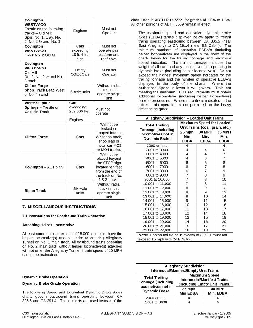
Covington WESTVACO Trestle on the following tracks – Old Mill: Spur, No, 1, Clay, No. 2, No. 2 ½ and No. 3
Engines Must not Operate
Covington WESTVACO Track No. 2 Old Mill
Cars exceeding 15 ft. 6 in.
high
Must not operate past platform and
roof eave Covington WESTVACO Old Mill No. 2, No. 2 ½ and No. 3 track
Empty CGLX Cars
Must not Operate
Clifton Forge Shop Track Lead West of No. 4 switch
6-Axle units
Without radial trucks must
operate single unit
White Sulphur Springs – Trestle on Coal bin Track
Cars exceeding 263,000 lbs. --------------- Engines
Must not operate
Clifton Forge Cars
Will not be kicked or
dropped into the West cab track,
shop lead or motor car MO3 or MO4 tracks.
Covington – AET plant Cars
Will not be placed beyond the STOP sign located ten feet from the end of the track on No.
1 & 2 tracks.
Ripco Track Six-Axle units
Without radial trucks must
operate single unit
7. MISCELLANEOUS INSTRUCTIONS 7.1 Instructions for Eastbound Train Operation Attaching Helper Locomotive All eastbound trains in excess of 15,000 tons must have the helper locomotive(s) attached prior to entering Alleghany Tunnel on No. 1 main track. All eastbound trains operating on No. 2 main track without helper locomotive(s) attached will not enter the Alleghany Tunnel if train speed of 10 MPH cannot be maintained. Dynamic Brake Operation
Dynamic Brake Grade Operation The following Speed and Equivalent Dynamic Brake Axles charts govern eastbound trains operating between CA 305.5 and CA 291.4. These charts are used instead of the
chart listed in ABTH Rule 5559 for grades of 1.0% to 1.5%. All other portions of ABTH 5559 remain in effect. The maximum speed and equivalent dynamic brake
axles (EDBA) tables displayed below apply to freight trains operating eastbound between CA 305.5 (near East Alleghany) to CA 291.4 (near BS Cabin). The minimum numbers of operative EDBA’s (including helper locomotives) are displayed in the body of the charts below for the trailing tonnage and maximum speed indicated. The trailing tonnage includes the weight of all cars and any locomotives not operating in dynamic brake (including helper locomotives(. Do not exceed the highest maximum speed indicated for the trailing tonnage and the number of operative EDBA’s displayed in the body of the charts. Where the Authorized Speed is lower it will govern. Train not meeting the minimum EDBA requirements must obtain additional locomotives (including helper locomotives) prior to proceeding. Where no entry is indicated in the tables, train operation is not permitted on the heavy descending grade.
Alleghany Subdivision – Loaded Unit Trains
Maximum Speed for Loaded Unit Trains (coal, grain, etc.) Total Trailing
Tonnage (including locomotives not in
Dynamic Brake
25 mph Min
EDBA
30 MPH Min.
EDBA
35 MPH Min.
EDBA 2000 or less 4 4 4 2001 to 3000 4 4 6 3001 to 4000 4 4 7 4001 to 5000 4 6 7 5001 to 6000 6 6 8 6001 to 7000 6 7 8 7001 to 8000 6 7 9 8001 to 9000 7 8 9
9001 to 10,000 7 8 10 10,001 to 11,000 7 8 11 11,001 to 12,000 8 9 12 12,001 to 13,000 8 9 13 13,001 to 14,000 8 10 14 14,001 to 15,000 9 11 15 15,001 to 16,000 10 12 16 16,001 to 17,000 11 13 17 17,001 to 18,000 12 14 18 18,001 to 19,000 13 15 19 19,001 to 20,000 14 16 20 20,001 to 21,000 15 17 21 21,000 to 22,000 16 18 22
Note: Eastbound trains in excess of 22,001 must not exceed 15 mph with 24 EDBA’s.
Alleghany Subdivision Intermodal/Manifest/Empty Unit Trains
Maximum Speed Intermodal/Manifest Trains
(including Empty Unit Trains)
Total Trailing Tonnage (including locomotives not in
Dynamic Brake 35 mph Min EDBA
40 MPH Min. EDBA
2000 or less 4 4 2001 to 3000 4 6
CSX Transportation ALLEGHANY SUBDIVISION – AG Effective January 1, 2005 Huntington Division East Timetable No. 1 © Copyright 2005
3001 to 4000 6 6 4001 to 5000 6 7 5001 to 6000 7 7 6001 to 7000 7 8 7001 to 8000 7 8 8001 to 9000 8 9
9001 to 10,000 8 9 10,001 to 11,000 9 10 11,001 to 12,000 9 10 12,001 to 13,000 10 11 13,001 to 14,000 10 12 14,001 to 15,000 11 13 15,001 to 16,000 11 14 16,001 to 17,000 12 15 17,001 to 18,000 12 16
Brake Pipe Pressure
The brake pipe pressure on the rear of freight trains must not be less than 10 pounds below the regulating valve setting before starting to descend the grade between East Alleghany and Covington.
Brake Application
Eastward freight trains leaving Alleghany will make an initial brake pipe reduction of not less than six (6) pounds at a speed and location which will not cause the train to stall. After the initial brake pipe reduction has been made, the engineer will regulate the speed of the train with the dynamic brake, if available. If the dynamic brake will not hold the train, is not available or becomes inoperative, additional brake pipe reductions should be made in one (1) or two (2) pound increments to control the speed. Releasing Train Brakes
One running release of the train brakes may be made between Alleghany and CA 296.0 when all of the following conditions have been met:
1. Train speed is 25 MPH or less;
2. Brake pipe reduction has not exceeded 15 pounds;
3. Train has 160 cars or less; and
4. Head end consist has a minimum of 8 axles of operative dynamic brake.
If all of these conditions are not met and it is necessary to release train brakes, the train will be stopped. If a running release is made, engineers must ensure that train brakes are reapplied before the train speed becomes excessive and that the reapplication is at least three (3) pounds greater than the previous reduction. If the total brake pipe reduction has not exceeded 15 pounds it will not be necessary to apply hand brakes before starting the train. Stopping Between East Alleghany and CA293.0
If the total reduction has exceeded 15 pounds, the brake pipe must be recharged. Hand brakes must be set, then the brake pipe will be charged for 30 minutes unless it is known that the pressure on the rear is restored to within five (5) pounds of the pressure indicated at the rear before entering Alleghany Tunnel. When starting the train between East Alleghany and CA 302.0, apply brakes with a straightaway service application of at least 10 pounds before the train speed exceeds 15 MPH. When starting an eastbound train between CA 302.0 and CA 293.0, apply
train air brakes with a straightaway application of at least ten (10) pounds before the train speed exceeds 10 MPH.
NOTES 7.2 Supplemental Speed Restriction Chart
Between Location/Milepost Psgr MPH
Frt MPH
CA 276.0 and CA 280.8 – Trains in excess of 10,000 tons
-
25
CA 276.0 and CA 354.6 – Trains in excess of 14,000 tons
-
CA 280.8 and CA 306.7 – eastbound trains
- 35
CA 275.8 and CA 277.1 35 35 CA 277.1 and CA 277.8 20 20
CSX Transportation ALLEGHANY SUBDIVISION – AG Effective January 1, 2005 Huntington Division East Timetable No. 1 © Copyright 2005
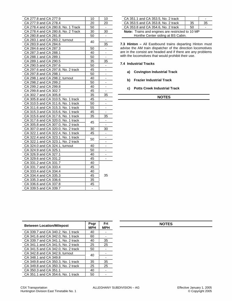
CA 277.8 and CA 277.9 10 10 CA 277.9 and CA 278.4 20 20 CA 278.4 and CA 280.8, No. 1 Track 50 - CA 278.4 and CA 280.8, No. 2 Track 30 30 CA 280.8 and CA 281.8 50 - CA 283.1 and CA 283.2, turnout - CA 283.9 and CA 284.6
40 35
CA 284.6 and CA 287.3 50 - CA 287.3 and CA 288.1 40 - CA 288.1 and CA 289.1 50 - CA 289.1 and CA 290.5 35 35 CA 290.5 and CA 297.6 50 - CA 297.6 and CA 297.8, No. 2 track 45 - CA 297.8 and CA 298.1 50 - CA 298.1 and CA 298.2, turnout 40 - CA 298.2 and CA 299.2 50 - CA 299.2 and CA 299.8 40 - CA 299.8 and CA 302.7 45 - CA 302.7 and CA 305.8 35 35 CA 305.8 and CA 310.5, No. 1 track 45 - CA 310.5 and CA 311.6, No. 1 track 50 - CA 311.6 and CA 315.3, No. 1 track 55 - CA 315.3 and CA 315.6, No. 1 track 45 - CA 315.6 and CA 317.6, No. 1 track 35 35 CA 317.6 and CA 320.0, No. 1 track - CA 305.8 and CA 307.0, No. 2 track
45 -
CA 307.0 and CA 320.0, No. 2 track 30 30 CA 322.1 and CA 322.4, No. 1 track 45 - CA 322.4 and CA 323.1, No. 1 track - CA 322.1 and CA 323.1, No. 2 track
50 -
CA 324.0 and CA 324.1, turnout 40 - CA 324.9 and CA 325.1 50 - CA 326.9 and CA 327.1 40 - CA 329.6 and CA 331.2 45 - CA 331.2 and CA 331.7 40 CA 331.7 and CA 333.4 45 CA 333.4 and CA 334.4 40 CA 334.4 and CA 335.3 45 CA 335.3 and CA 336.6 35 CA 336.6 and CA 337.8 45 CA 339.5 and CA 339.7 -
35
Between Location/Milepost Psgr MPH
Frt MPH
CA 339.7 and CA 340.2, No. 1 track 40 - CA 341.6 and CA 342.0, No. 1 track 60 - CA 339.7 and CA 341.1, No. 2 track 40 35 CA 341.1 and CA 341.5, No. 2 track 25 25 CA 341.5 and CA 342.0, No. 2 track 50 - CA 342.8 and CA 342.9, turnout - CA 348.1 and CA 349.8
40 -
CA 349.8 and CA 350.3, No. 1 track 35 35 CA 349.8 and CA 350.3, No. 2 track 25 25 CA 350.3 and CA 351.1 40 - CA 351.1 and CA 354.6, No. 1 track 50 -
CA 351.1 and CA 353.5, No. 2 track - CA 353.5 and CA 353.8, No. 2 track 35 35 CA 353.8 and CA 354.6, No. 2 track 50 - Note: Trains and engines are restricted to 10 MP
Honthe Center siding at BS Cabin. 7.3 Hinton – All Eastbound trains departing Hinton must advise the AM train dispatcher of the direction locomotives are in the consist are headed and if there are any problems with the locomotives that would prohibit their use. 7.4 Industrial Tracks
a) Covington Industrial Track b) Frazier Industrial Track c) Potts Creek Industrial Track
NOTES
NOTES

CSX Transportation ALLEGHANY SUBDIVISION – AG Effective January 1, 2005 Huntington Division East Timetable No. 1 © Copyright 2005
NOTES
CSX Transportation BIG COAL SUBDIVISION - BX Effective January 1, 2005 Huntington Division East Timetable No. 1 © Copyright 2005
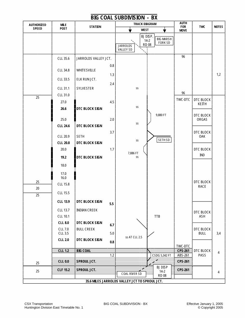
BIG COAL SUBDIVISION - BX TRACK DIAGRAM AUTHORIZED
SPEED MILE POST STATION
WEST
AUTH FOR
MOVE TWC NOTES
96
CLL 35.6 JARROLDS VALLEY JCT.
0.8 CLL 34.8 WHITESVILLE 1.3 CLL 33.5 ELK RUN JCT. 2.4 CLL 31.1 SYLVESTER ss 96
1,2
CLL 31.0 25
27.0 4.5 TWC-DTC
ss
DTC BLOCK KEITH
26.6 DTC BLOCK SIGN
9,880 FT DTC BLOCK 25.0 2.0 ORGAS ss
CLL 24.6 DTC BLOCK SIGN
3.7 DTC BLOCK CLL 20.9 SETH OAK ss
CLL 20.8 DTC BLOCK SIGN
20.0 1.7 DTC BLOCK
7,886 FT ss
IND
19.2 DTC BLOCK SIGN
18.0
17.0 16.0 25 DTC BLOCK
CLL 15.8 RACE 20
25 CLL 15.5
CLL 13.9 DTC BLOCK SIGN 5.5
CLL 13.7 INDIAN CREEK DTC BLOCK CLL 10.1 ASH
CLL 8.0 DTC BLOCK SIGN 6.7
CLL 7.0 BULL CREEK DTC BLOCK CLL 3.5 5.0 BULL 3,4 ss AT CLL 2.5
CLL 2.0 DTC BLOCK SIGN 0.8
TWC-DTC CLL 1.2 BIG COAL CPS-261 DTC BLOCK 1.2 CSDG 5,342 FT ABS-261 PASS
25 CLL 0.0 SPROUL JCT.
CPS-261
4
25 CLF 15.2 SPROUL JCT.
CPS-261
4
35.6 MILES JARROLDS VALLEY JCT TO SPROUL JCT.
BIG MARSH FORK SD
BJ DISP. 14-2
RD 08 JARROLDS VALLEY SD
TTB
SETH SD
COAL RIVER SD
BJ DISP 14-2
RD 08

CSX Transportation BIG COAL SUBDIVISION - BX Effective January 1, 2005 Huntington Division East Timetable No. 1 © Copyright 2005
STATION PAGE NOTES NOTE 1: All trains entering or operating between MP CLL 31.0 and MP CLL 35.6 will operate according to Rule 96 and must receive instructions from
the Elk Run yardmaster (when on duty) before lining switches or fouling tracks. The Elk Run yardmaster (when on duty) will issue instructions to crews operating between these mileposts.
NOTE 2: Prior to occupying tracks between MP CLL 31.0 and MP CLL 35.6, engineering forces will make arrangements with the Elk Run yardmaster (when on duty), who is responsible for directing movements on those tracks.
NOTE 3: Westbound signal located at MP CLL 3.5 is equipped with an APP Plate. This signal only conveys information about WAS signal at MP CLL 2.0.
NOTE 4: Signals between MP CLL 0.0 and MP CLL 2.0 convey signal aspects in accordance with Signal Aspect Rules C1281-C1298.

CSX Transportation BIG COAL SUBDIVISION - BX Effective January 1, 2005 Huntington Division East Timetable No. 1 © Copyright 2005
BIG COAL SUBDIVISION SPECIAL INSTRUCTIONS 1. INSTRUCTIONS RELATING TO OPERATING
RULES Spring Switches
Location Normal Position
Facing Speed
When Springing
West End Joe Creek Siding MP CLL 19.2 Siding 10
MPH East End Joe Creek Siding MP CLL 20.8 Main 25
MPH West End Crown Siding MP CLL 24.5 Siding 10
MPH East End Crown Siding MP CLL 26.6 Main 25
MPH
Sylvester Spring Switch MP CLL 31.1
No. 2 Yard Track
10 MPH
Fork Creek Spring Switch MP CLL 2.5
Main 25 MPH
10 MPH
Hand Brakes - Cars Location Loaded Empty Comments Elk Run Yard 7 HB 4 HB On 150 Cars
Sylvester 10% 5% WE of Loads EE of Empties
Bull Creek 15% 10% -- CLL 0.0
to CLL 27.0
4% 4% Main & Sidings
LDS on West End ERY on East End
Crown Siding 10% 2 HB East End
Orgas Block 4 HB -- West End Hand-Operated Derails Crews may leave the derail at Fork Creek mine MP CLL 2.5 in the non-derailing position when departing mine provided that: 1) They have departed the mine with their entire train,
and 2) Mine tracks are known to be clear of all standing rail
equipment. 2. INSTRUCTIONS RELATING TO SAFETY
RULES Exceptions to Making A Safety STOP Employees will make the safety STOP as required by Safety Rule 2201 in all cases except at the locations described below:
1) Homer III Mine – When doubling up loaded trains at Homer III Mine.
2) Bull Creek Mine – When doubling up loaded trains
Crews doubling up loaded trains at the above listed locations must comply with safety rules and SOFA recommendations except for a safety STOP and must comply with the following:
1) A job briefing must be conducted in which the movement to be made is discussed.
2) Employees must not ride to the coupling. 3) Employees must not mount or dismount moving
equipment. 4) When radios are used for communication, crews
must give clear and accurate car lengths for the movement to be made.
3. INSTRUCTIONS RELATING TO COMPANY
POLICIES AND PROCEDURES
NONE 4. INSTRUCTIONS RELATING TO EQUIPMENT
HANDLING RULES
NONE 5. INSTRUCTIONS RELATING TO AIR BRAKE
AND TRAIN HANDLING RULES
NONE 6. INSTRUCTIONS RELATING TO EQUIPMENT
RESTRICTIONS
NONE 7. MISCELLANEOUS
NONE
NOTES

CSX Transportation BIG COAL SUBDIVISION - BX Effective January 1, 2005 Huntington Division East Timetable No. 1 © Copyright 2005
NOTES
NOTES

CSX Transportation BIG MARSH FORK SUBDIVISION - BM Effective January 1, 2005 Huntington Division East Timetable No. 1 © Copyright 2005
BIG MARSH FORK SUBDIVISION - BM TRACK DIAGRAM AUTHORIZED
SPEED MILE POST STATION
WEST
AUTH FOR
MOVE TWC NOTES
END OF TRACK 20 CLQ 7.4 SUNDIAL TWC-DTC
0.2 CLQ 7.2 EDWIGHT
DTC BLOCK SUN
CLQ 6.1 DTC BLOCK SIGN
2.2 CLQ 5.0 MONTCOAL DTC BLOCK 3.0 MONT 3 CLQ 2.0 EUNICE 1.0 TWC-DTC
CLQ 1.0 DTC BLOCK SIGN 96
20 CLQ 0.0 JARROLDS VALLEY JCT. 96
96
CLL 35.6 JARROLDS VALLEY JCT.
1,2
96
7.4 MILESSUNDIAL TO JARROLDS VALLEY JCT.
STATION PAGE NOTES NOTE 1: All trains entering or operating between MP CLL 31.0 and MP CLL 35.6 will operate according to Rule 96 and must receive instructions from
the Elk Run yardmaster (when on duty) before lining switches or fouling tracks. The Elk Run yardmaster (when on duty) will issue instructions to crews operating between these mileposts.
NOTE 2: Prior to occupying tracks between MP CLL 31.0 and MP CLL 35.6, engineering forces will make arrangements with the Elk Run yardmaster (when on duty) who is responsible for directing movements on those tracks.
NOTE 3: Westbound trains will contact the Elk Run yardmaster (when on duty) for instructions before passing MP CLQ 2.5.
BJ DISP. 14-2
RD 08
MARFORK IT
JARROLDS VALLEY SD
BIG COAL SD
BJ DISP. 14-2
RD 08

CSX Transportation BIG MARSH FORK SUBDIVISION - BM Effective January 1, 2005 Huntington Division East Timetable No. 1 © Copyright 2005
BIG MARSH FORK SUBDIVISION SPECIAL INSTRUCTIONS 1. INSTRUCTIONS RELATING TO OPERATING RULES Hand-Operated Switches Marfork IT Switch Main line switch to Marfork IT will be left in the position last used. Trains must approach this switch expecting it to be lined against their movement. Jarrolds Valley Jct. Normal position for the Jarrolds Valley Jct. switch is lined for movement to the Big Marsh Fork SD.
2. INSTRUCTIONS RELATING TO SAFETY
RULES
NONE
3. INSTRUCTIONS RELATING TO COMPANY POLICIES AND PROCEDURES
NONE
4. INSTRUCTIONS RELATING TO EQUIPMENT
HANDLING RULES
NONE 5. INSTRUCTIONS RELATING TO AIR BRAKE
AND TRAIN HANDLING RULES
NONE 6. INSTRUCTIONS RELATING TO EQUIPMENT
RESTRICTIONS
NONE 7. MISCELLANEOUS
7.1 Industrial Tracks
A. Marfork Industrial Track
A.1 Hand Brakes - Cars Location Loaded Empty Comments Marfork 25% 10% - West of Marfork Switch (CLQ 1.0) 10% 3 HB East end of
cut
NOTES

CSX Transportation BRIDGEPORT SUBDIVISION - PU Effective January 1, 2005 Huntington Division East Timetable No. 1 © Copyright 2005
BRIDGEPORT SUBDIVISION - PU TRACK DIAGRAM AUTHORIZED
SPEED MILE POST STATION
WEST
AUTH FOR
MOVE TWC NOTES
20
BA 281.6 BERKELEY RUN JCT.
CPS-261
(193) YL
35 ABS-251
(193) 1
BA 281.6 BERKELEY RUN JCT.
1=WB 2=EB YL
BA 283.0
9.9 ABS-251
DTC BLOCK WEB
BA 291.5 RS TOWER
CPS-261 293.0 294.0 BA 294.2 FOURCO
ABS-261
7.5 BA 299.0 LODGEVILLE CPS-261 DTC BLOCK BA 300.3 EAS MP 300 PINTO BA 300.4
ABS-261 35
BA 301.0
2.4 BA 301.4 MO TOWER CPS-261 2 BA 301.5 ABS-261
35 WESTBOUND
TRAIN SEE NOTE 2
35
BA 301.6
BA 302.7 CLARKSBURG
1.5 ABS-261 BA 302.9 MD TOWER EQHR 4453 CPS-261 DTC BLOCK 0.5 CLARK 0.1
ABS-261
35
BA 303.4 J TOWER. EQHR 4453
CPS-261
1
BNA 58.1 J TOWER TWC-DTC 25
DTC BLOCK SHORT
21.8 MILES BERKELEY RUN JCT. TO SHORT LINE JCT.
STATION PAGE NOTES
NOTE 1: All Signals are Signal Rules 1281 – 1298. NOTE 2: Westbound trains 10 MPH, head end only.
CI DISP. 14-8
RD 08
MERRICK ENGINEERING IT
NO. 1 TUNNEL
MOUNTAIN SUB
FOURCO IT
SHORT LINE SD CJ DISP. 14-3 RD 08
2 1
CJ DISP. 14-8
RD 08
1 2
GRASSELLI IT

CSX Transportation BRIDGEPORT SUBDIVISION - PU Effective January 1, 2005 Huntington Division East Timetable No. 1 Copyright 2005
BRIDGEPORT SUBDIVISION SPECIAL INSTRUCTIONS 1. INSTRUCTIONS RELATING TO OPERATING
RULES Standard Clocks Station Location Grafton Crew Room Hand Brakes - Cars Standing Equipment Hand Brake Application Between Location/Milepost Loads Empties BA 281.6 and BA 284.5 20% 10% BA 284.5 and BA 289.0 50% 25% BA 289.0 and BA 298.0 20% 10% BA 298.0 and BA 303.5 50% 25% 2. INSTRUCTIONS RELATING TO SAFETY
RULES
NONE 3. INSTRUCTIONS RELATING TO COMPANY
POLICIES AND PROCEDURES
NONE 4. INSTRUCTIONS RELATING TO EQUIPMENT
HANDLING RULES LOCATION EQUIPMENT RESTRICTION Fourco IT Grasselli IT
Six-Axle units Must Not Operate
5. INSTRUCTIONS RELATING TO EQUIPMENT
RESTRICTIONS
5.1 Cars with gross weight of 251,000 lbs. or greater must not operate on Grasselli IT.
6. INSTRUCTIONS RELATING TO AIR BRAKE
AND TRAIN HANDLING RULES Stretch Braking Stretch braking may be used between the following locations: Westbound trains – Between BA 290.5 and BA 291.6 Between BA 295.5 and BA 296.0 7. MISCELLANEOUS
7.1 Industrial Tracks
A. Fourco Industrial Track 1. Movements are governed by Rule 96. 2. Only 4-axle units may operate.
B. Merrick Engineering IT 1. Movements are governed by Rule 96.
C. Grasselli IT 1. Movements are governed by Rule 96.
a. Crews must obtain permission from the train dispatcher before occupying this track.
b. Crews must obtain permission from the train dispatcher before exiting this track. After exiting this track crews must report clear to the train dispatcher.
NOTES

CSX Transportation BUFFALO SUBDIVISION - BF Effective January 1, 2005 Huntington Division East Timetable Division No. 1 Copyright 2005
BUFFALO SUBDIVISION – BF TRACK DIAGRAM AUTHORIZED
SPEED MILE POST STATION
WEST
AUTH FOR MOVE TWC NOTES
END OF TRACK TWC-DTC 20 CLU 16.6 END OF TRACK
DTC BLOCK SAND
CLU 14.3 DTC BLOCK SIGN
20
DTC BLOCK FITCH
25
CLU 13.0 DTC BLOCK SIGN
DTC BLOCK BAKE TWC-DTC
CLU 7.0 DTC BLOCK SIGN 193 YL
25 10
CLU 6.3
12.5 CLU 4.1 FANCO
10 25
CLU 4.0
193 YL
CLU 3.2 DTC BLOCK SIGN
TWC-DTC
CLU 0.4
TWC-DTC 1
25 4.1 (ABS) 10
MAINLINE JCT SW CLU 0.0 DTC BLOCK SIGN
DTC BLOCK HERST
10
MAINLINE JCT SW CLS 78.6 MAN JCT
CPS-261
1
DTC BLOCK ABS-261 MAN
16.6 MILES END OF TRACK TO MAN
STATION PAGE NOTES
NOTE 1: Signal aspects displayed are in accordance with Rules C1281-C1298.
BJ DISP. 14-2
RD 08
LOGAN SD BJ DISP. 14-4
RD 08

CSX Transportation BUFFALO SUBDIVISION - BF Effective January 1, 2005 Huntington Division East Timetable Division No. 1 Copyright 2005
BUFFALO SUBDIVISION SPECIAL INSTRUCTIONS 1. INSTRUCTIONS RELATING TO OPERATING RULES Hand-Operated Switches Fanco Mine Track Switch at the west end of Fanco mine, MP CLU 4.1, will be left lined for the Fanco mine track. Switch to Buffalo Subdivision Normal position for the switch to the Buffalo Subdivision is lined for movement to the Buffalo Subdivision. Radio Stations and Instructions Hyco (Peach Creek) yardmaster call-in number is 4. 2. INSTRUCTIONS RELATING TO SAFETY
RULES
NONE 3. INSTRUCTIONS RELATING TO COMPANY
POLICIES AND PROCEDURES
NONE 4. INSTRUCTIONS RELATING TO EQUIPMENT
HANDLING RULES
NONE 5. INSTRUCTIONS RELATING TO EQUIPMENT
RESTRICTIONS
NONE 6. INSTRUCTIONS RELATING TO AIR BRAKE
AND TRAIN HANDLING RULES
NONE
7. MISCELLANEOUS Main track between MP CLU 6.2 and end of track is out of service.
NOTES
NOTES
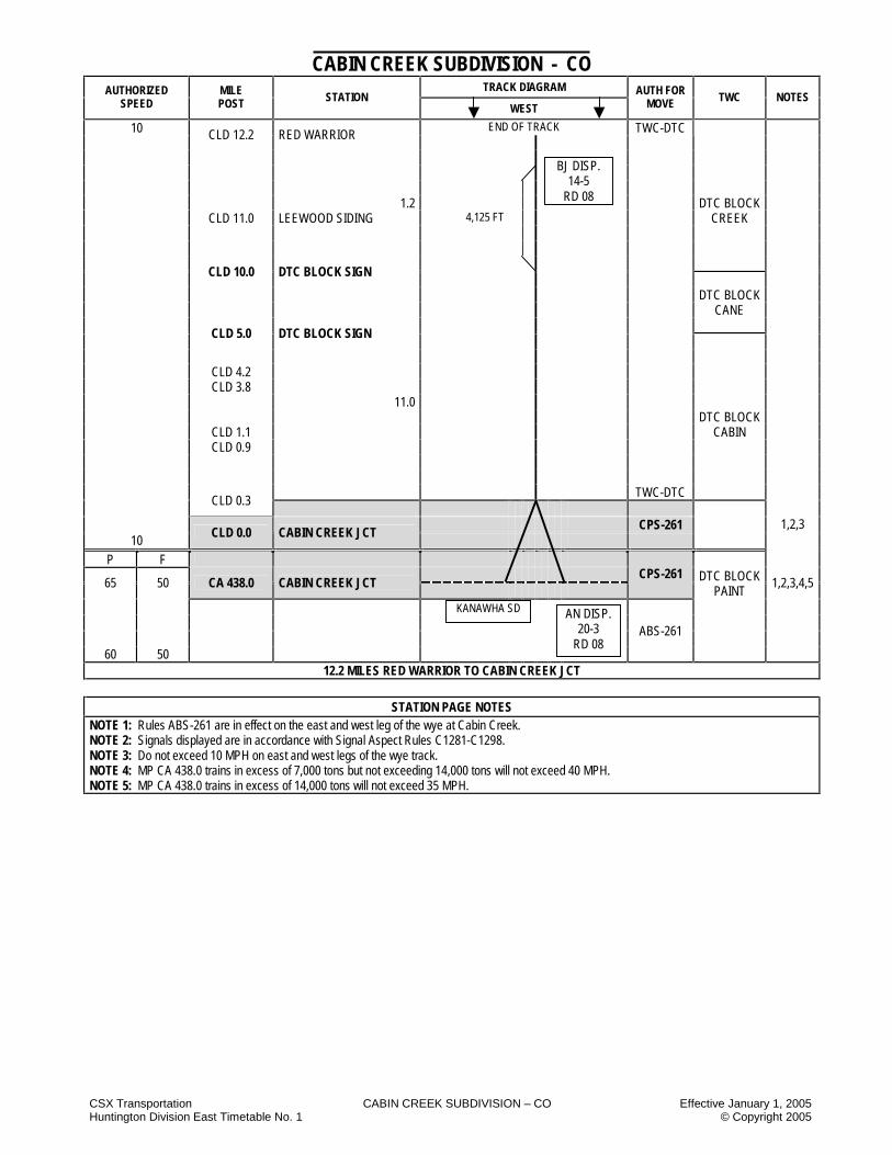
CSX Transportation CABIN CREEK SUBDIVISION – CO Effective January 1, 2005 Huntington Division East Timetable No. 1 © Copyright 2005
CABIN CREEK SUBDIVISION - CO TRACK DIAGRAM AUTHORIZED
SPEED MILE POST STATION
WEST
AUTH FOR MOVE TWC NOTES
END OF TRACK 10 CLD 12.2 RED WARRIOR TWC-DTC
1.2 DTC BLOCK CLD 11.0 LEEWOOD SIDING 4,125 FT CREEK
CLD 10.0 DTC BLOCK SIGN
DTC BLOCK CANE
CLD 5.0 DTC BLOCK SIGN
CLD 4.2 CLD 3.8 11.0 DTC BLOCK
CLD 1.1 CABIN CLD 0.9
TWC-DTC
CLD 0.3
CPS-261 10
CLD 0.0 CABIN CREEK JCT
1,2,3
P F
65 50 CA 438.0 CABIN CREEK JCT
CPS-261 DTC BLOCK PAINT
1,2,3,4,5
ABS-261
60 50
12.2 MILES RED WARRIOR TO CABIN CREEK JCT
STATION PAGE NOTES NOTE 1: Rules ABS-261 are in effect on the east and west leg of the wye at Cabin Creek. NOTE 2: Signals displayed are in accordance with Signal Aspect Rules C1281-C1298. NOTE 3: Do not exceed 10 MPH on east and west legs of the wye track. NOTE 4: MP CA 438.0 trains in excess of 7,000 tons but not exceeding 14,000 tons will not exceed 40 MPH. NOTE 5: MP CA 438.0 trains in excess of 14,000 tons will not exceed 35 MPH.
BJ DISP. 14-5
RD 08
KANAWHA SD AN DISP. 20-3
RD 08
CSX Transportation CABIN CREEK SUBDIVISION – CO Effective January 1, 2005 Huntington Division East Timetable No. 1 © Copyright 2005
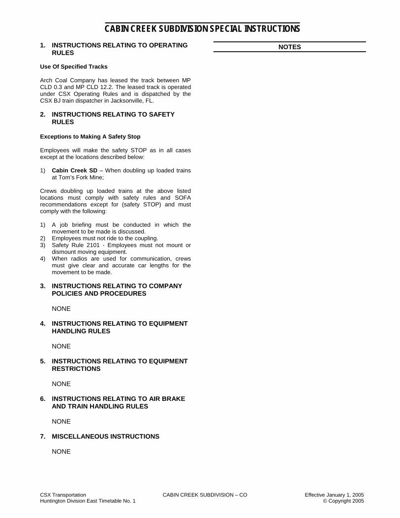
CABIN CREEK SUBDIVISION SPECIAL INSTRUCTIONS 1. INSTRUCTIONS RELATING TO OPERATING
RULES Use Of Specified Tracks Arch Coal Company has leased the track between MP CLD 0.3 and MP CLD 12.2. The leased track is operated under CSX Operating Rules and is dispatched by the CSX BJ train dispatcher in Jacksonville, FL. 2. INSTRUCTIONS RELATING TO SAFETY
RULES Exceptions to Making A Safety Stop Employees will make the safety STOP as in all cases except at the locations described below: 1) Cabin Creek SD – When doubling up loaded trains
at Tom’s Fork Mine; Crews doubling up loaded trains at the above listed locations must comply with safety rules and SOFA recommendations except for (safety STOP) and must comply with the following: 1) A job briefing must be conducted in which the
movement to be made is discussed. 2) Employees must not ride to the coupling. 3) Safety Rule 2101 - Employees must not mount or
dismount moving equipment. 4) When radios are used for communication, crews
must give clear and accurate car lengths for the movement to be made.
3. INSTRUCTIONS RELATING TO COMPANY POLICIES AND PROCEDURES
NONE 4. INSTRUCTIONS RELATING TO EQUIPMENT
HANDLING RULES
NONE 5. INSTRUCTIONS RELATING TO EQUIPMENT
RESTRICTIONS
NONE 6. INSTRUCTIONS RELATING TO AIR BRAKE
AND TRAIN HANDLING RULES
NONE 7. MISCELLANEOUS INSTRUCTIONS NONE
NOTES

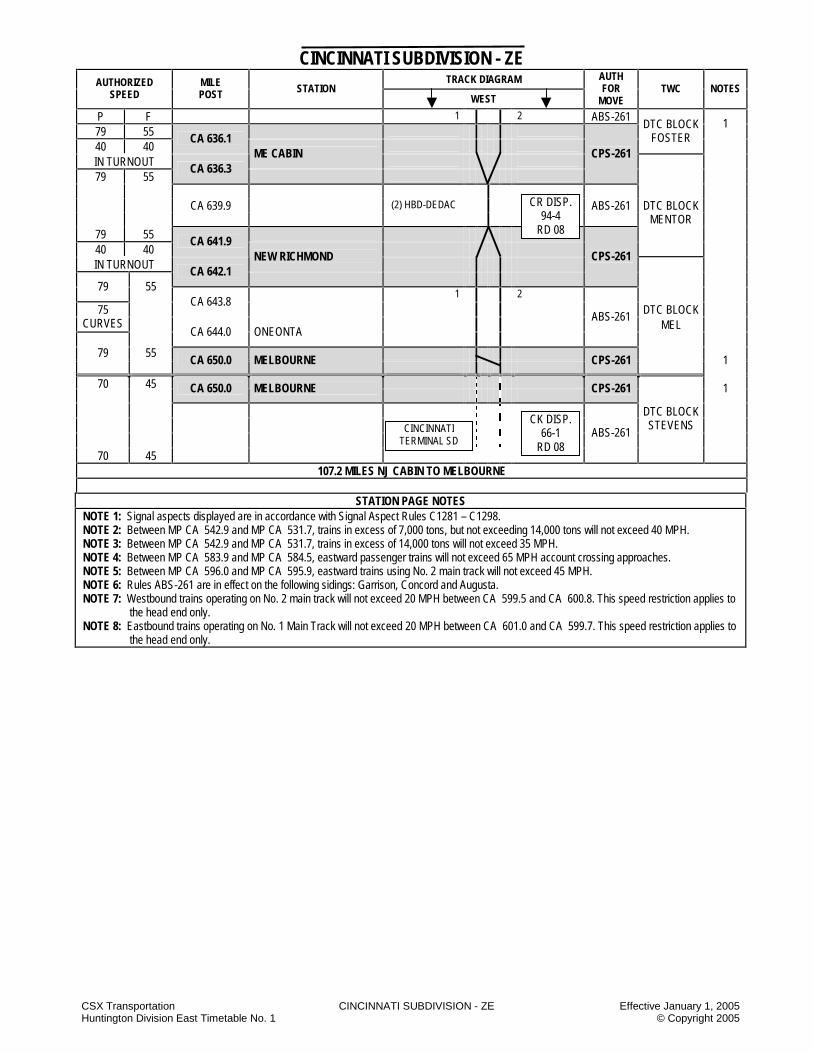
CSX Transportation CINCINNATI SUBDIVISION - ZE Effective January 1, 2005 Huntington Division East Timetable No. 1 © Copyright 2005
CINCINNATI SUBDIVISION - ZE TRACK DIAGRAM AUTHORIZED
SPEED MILE POST STATION
WEST
AUTH FOR
MOVE TWC NOTES
P F
ABS-261 79 55
CA 542.9 NJ CABIN 1 2 CPS-261
DTC BLOCK SCIOTO
1,2,3 55 CA 542.9 NJ CABIN CPS-261 1 79 1 2
CA 543.0 75
CURVES ABS-261 CA 543.7 5.0 79 55
CA 547.5 45 45
DTC BLOCK
CA 547.9 TAYLOR
CPS-261 KOT
CA 548.1 SOUTH SHORE
45 45 ABS-261 CA 548.8 2.3 79 55
40 40
IN TURNOUT CA 550.2 S. PORTSMOUTH
CPS-261
79 55
CA 550.4 70
CURVES CA 551.3 (1) HBD-DEDAC 79 ABS-261
CA 562.1 DTC BLOCK 70
CURVES GARRI
CA 562.4 13.6 79
CA 563.8 E.E. GARRISON SDG
CPS-261
6
SSDG 15,640 FT 3.1
ABS-261
79
CA 566.9 W.E. GARRISON SDG
CPS-261 75
CURVES ABS-261
CA 567.3 79
CA 570.1 70
CURVES CA 570.6 79 55 5.1 DTC BLOCK
CA 571.2 VANCE
CA 572.0 VANCEBURG 30 30 CA 572.2 65
CURVES 55
CA 572.6 79
CA 573.0 (1) HBD-DEDAC
79 55 ABS-261 1
CR DISP. 94-4
RD 08
CR DISP. 94-4
RD 08
NORTHERN SD

CSX Transportation CINCINNATI SUBDIVISION - ZE Effective January 1, 2005 Huntington Division East Timetable No. 1 © Copyright 2005
CINCINNATI SUBDIVISION - ZE TRACK DIAGRAM AUTHORIZED
SPEED MILE POST STATION
WEST
AUTH FOR
MOVE TWC NOTES
P F
1
79 55 8.8
ABS-261
DTC BLOCK
CA 580.8 E.E. CONCORD SDG
CPS-261 VANCE
6
SSDG 14,740 FT 3.0
ABS-261
CA 583.8 W.E. CONCORD SDG
CPS-261
6
ABS-261 79
CA 583.9
65 NOTE 4
4
CA 584.5
79
CA 590.3 75
CURVES
CA 590.8 DTC BLOCK
CA 594.6 (1) HBD-DEDAC TRINT 79
CA 594.2 70
CURVES
CA 594.6 79
CA 595.7 70
CURVES 12.1 ABS-261 CA 596.3 60
TURNOUT CA 596.1 CPS-261 CA 595.9
SPRINGDALE
5
79 55 1 2 ABS-251 CA 598.9 35 35
CA 599.5 7 CA 599.7 8 CA 600.8 DTC BLOCK 7 CA 601.0 1=WB DALE 8 6.1 2=EB CA 602.0 MAYSVILLE
35 35
CA 602.9 1.5 ABS-251 79 55
CA 603.5 WEST MAYSVILLE
CPS-261 MAYS
79 ABS-261
CA 604.2 70
CURVES
CA 604.4 2.8
CA 606.2 BH CABIN 79
CSDG 6,038 FT.
CA 607.4
75 CURVES
79 55 CA 608.3
1 2 ABS-261 MAYS 1
MAYSVILLE YARD
TTI RR
CR DISP. 94-4
RD 08

CSX Transportation CINCINNATI SUBDIVISION - ZE Effective January 1, 2005 Huntington Division East Timetable No. 1 © Copyright 2005
CINCINNATI SUBDIVISION - ZE TRACK DIAGRAM AUTHORIZED
SPEED MILE POST STATION
WEST
AUTH FOR
MOVE TWC NOTES
P F
2.2 1 2 ABS-261 DTC BLOCK 1
79 55 MAYS 40 40
CA 608.4
IN TURNOUT LC CABIN
CA 608.6
CPS-261
75 CURVES ABS-261 CA 608.8
79 55
CA 611.6 35 35 CA 612.8 79 55
CA 613.5
70 CURVES
CA 614.0
79
CA 615.8 DTC BLOCK
CA 616.4 (1) HBD-DEDAC AUGUSTA 70
CURVES CA 617.3
79 55
CA 618.3 11.2 ABS-261
CA 619.6 E.E. AUGUSTA SDG
CPS-261
6 25 25
CA 619.7 79 55 SSDG 10,670 FT ABS-261
CA 620.6
75 CURVES
79 CA 620.7
2.2
CA 621.8 W.E. AUGUSTA SDG
CPS-261
6
79
CA 622.6 75
CURVES
CA 622.7 ABS-261 79
DTC BLOCK
CA 628.7 BRAD 75
CURVES CA 629.7
8.7 79 55 40 40
CA 630.4
IN TURNOUT FOSTER
CA 630.6
CPS-261
70 CURVES
55 1 2 DTC BLOCK
79 CA 631.1
3.3 ABS-261
CARN
CA 633.8 CARNTOWN
CPS-261
79 DTC BLOCK
CA 634.0 FOSTER 75
CURVES
79 55 CA 634.3
ABS-261
1
CR DISP. 94-4
RD 08
CSX Transportation CINCINNATI SUBDIVISION - ZE Effective January 1, 2005 Huntington Division East Timetable No. 1 © Copyright 2005
CINCINNATI SUBDIVISION - ZE TRACK DIAGRAM AUTHORIZED
SPEED MILE POST STATION
WEST
AUTH FOR
MOVE TWC NOTES
P F 1 2 ABS-261 79 55
1
40 40 CA 636.1
DTC BLOCK FOSTER
IN TURNOUT
ME CABIN
79 55 CA 636.3
CPS-261
CA 639.9 (2) HBD-DEDAC ABS-261 DTC BLOCK MENTOR
79 55 40 40
CA 641.9
IN TURNOUT NEW RICHMOND
CA 642.1
CPS-261
79 55 1 2
CA 643.8
DTC BLOCK 75 CURVES MEL CA 644.0 ONEONTA
ABS-261
79 55
CA 650.0 MELBOURNE
CPS-261 1
70 45 CA 650.0 MELBOURNE
CPS-261 1
70 45
ABS-261
DTC BLOCK STEVENS
107.2 MILES NJ CABIN TO MELBOURNE
STATION PAGE NOTES
NOTE 1: Signal aspects displayed are in accordance with Signal Aspect Rules C1281 – C1298. NOTE 2: Between MP CA 542.9 and MP CA 531.7, trains in excess of 7,000 tons, but not exceeding 14,000 tons will not exceed 40 MPH. NOTE 3: Between MP CA 542.9 and MP CA 531.7, trains in excess of 14,000 tons will not exceed 35 MPH. NOTE 4: Between MP CA 583.9 and MP CA 584.5, eastward passenger trains will not exceed 65 MPH account crossing approaches. NOTE 5: Between MP CA 596.0 and MP CA 595.9, eastward trains using No. 2 main track will not exceed 45 MPH. NOTE 6: Rules ABS-261 are in effect on the following sidings: Garrison, Concord and Augusta. NOTE 7: Westbound trains operating on No. 2 main track will not exceed 20 MPH between CA 599.5 and CA 600.8. This speed restriction applies to
the head end only. NOTE 8: Eastbound trains operating on No. 1 Main Track will not exceed 20 MPH between CA 601.0 and CA 599.7. This speed restriction applies to
the head end only.
CR DISP. 94-4
RD 08
CK DISP. 66-1
RD 08
CINCINNATI TERMINAL SD

CSX Transportation CINCINNATI SUBDIVISION - ZE Effective January 1, 2005 Huntington Division East Timetable No. 1 © Copyright 2005
CINCINNATI SUBDIVISION SPECIAL INSTRUCTIONS
1. INSTRUCTIONS RELATING TO OPERATING RULES
Engine Bell The engine bell will be rung continuously while moving within the city of Maysville beginning at least 100 yards before reaching the first street crossing at grade and continuing until the engine has passed the last street crossing at grade. Engine Horn Trains approaching the following private crossings must sound whistle signal 14(l):
MP CA 606.0 MP CA 606.4 MP CA 648.9 MP CA 649.1
Highway Crossings at Grade Garrison Siding (CA 566.5) – Unless otherwise instructed by the train dispatcher or train length does not permit, do not block the private road crossing Anderson Lane All trains using the Country Mark industrial track (formerly No. 1 Main) must STOP and flag Anderson Lane crossing at MP CA 649.9 due to rusty rail conditions. South Shore - State Route 7 When EAS South Portsmouth displays an approach aspect, eastward trains will STOP at MP CA 548.7 and will contact the train dispatcher for instructions. Switching: Inland Container Switching Procedures: With the addition of protective blue lights and red strobe warning lights on the outbound warehouse, the inbound warehouse and A&E tracks, the following operating procedures are in effect when switching Inland Container: 1. STOP at the permanent derail and contact the mill
scheduler or control room by phone 606-564-2637. 2. Wait until the blue light has been turned off at the derail.
You must phone before advancing towards the mill. 3. STOP on the east side of the individual track’s blue light
and make person-to-person contact with area technicians working the inbound, outbound or A&E tracks.
4. After contacting area technicians, and being cleared to
enter these tracks, crews may enter and perform their switching.
The responsibility of the technicians after being contacted by the railroad crew is to: 1. Ensure the dock is safe and ready to be
switched with dock plates out and other area personnel notified.
2. Turn the blue light off. This will simultaneously activate the red strobe light. 3. After the rail crew has completed switching and
has exited the internal track, the rail crew will call on the phone at the derail and notify the mill scheduler or control room to let them know the rail crew has finished switching.
The procedure for allowing a railroad crew to enter the mill from the point of the permanent derail remains in place. A) Railroad crew will contact the mill scheduler and
request permission to enter the mill grounds to conduct switching operations.
B) Mill scheduler will call control room and ask that the inbound and A&E area technicians be notified that the railroad is here to perform switching operations.
C) After notifying the inbound and A&E area technicians, the control room will advise that those areas have been contacted.
D) Mill scheduler will then turn off the permanent derail blue light and announce “the railroad is on site” over the intercom.
E) During weekend, holiday or evening switching, the railroad will contact either the outbound technicians or the control room instead of the mill scheduler.
Hand Brakes Coroplast Plant, Vanceburg, KY MP CA 569.7 The lead between the Cincinnati SD main track and the industry tracks has a grade of 2.1% which is downhill towards the Cincinnati SD main track. When cars are left on this lead, 100% hand brakes must be applied. 2. INSTRUCTIONS RELATING TO SAFETY
RULES
NONE 3. INSTRUCTIONS RELATING TO COMPANY
POLICIES AND PROCEDURES
NONE

CSX Transportation CINCINNATI SUBDIVISION - ZE Effective January 1, 2005 Huntington Division East Timetable No. 1 © Copyright 2005
4. INSTRUCTIONS RELATING TO EQUIPMENT HANDLING RULES
NONE
5. INSTRUCTIONS RELATING TO AIR BRAKE AND
TRAIN HANDLING RULES Engine Speed Indicators and Odometers Engine speed indicators, odometers and HTD equipment must be checked at the first encountered milepost location, except as listed below: CA 589.0 and CA 590.0 CA 611.0 and CA 612.0 CA 628.0 and CA 630.0 6. INSTRUCTIONS RELATING TO EQUIPMENT
RESTRICTIONS Equipment Restrictions Location Equipment Restriction Taylor— Taylor Brick
Six Axle Units
Must Not Operate
Carntown – Black River Mining Co.
Engines Must Not Operate Through Loading Facility On Nos. 1
And 2 Tracks Carntown – Black River Mining Co.
Equipment Must Not Be Cut Off In Motion
7. MISCELLANEOUS
NONE
NOTES
NOTES

CSX Transportation COAL RIVER SUBDIVISION - CR Effective January 1, 2005 Huntington Division East Timetable No. 1 © Copyright 2005
COAL RIVER SUBDIVISION - CR TRACK DIAGRAM AUTHORIZED
SPEED MILE POST STATION
WEST
AUTH FOR
MOVE TWC NOTES
20
96
CLF 50.6 SHARPLES TWC-DTC
20 CLF 50.0
DTC BLOCK 10 IN CURVES SHARP
20 CLF 49.7
1.6
CLF 49.1 DTC BLOCK SIGN
CLF 49.0 CLOTHIER ss 11.7
DTC BLOCK CLOTH
CLF 44.0 DTC BLOCK SIGN
CLF 39.7 TTB TWC-DTC
DTC BLOCK POWELL
CLF 37.3 DTC BLOCK SIGN POND JCT. ss 193
0.2 CLF 37.1 MADISON
20 193
CLF 35.5 2.3 CLF 34.8 DANVILLE 96
1.9
25 CLF 32.9 ROCK CREEK
CPS-261
1 1.3 CLF 30.4 BETH MINE 2.5
CLF 27.9 JULIAN 25 ABS-261 DTC BLOCK
CLF 27.0 ROCK 10
IN CURVES 25
CLF 26.9 2.3
CLF 25.6 ADAMS
CLF 24.0 E.E. MACCORKLE
CPS-261
CSDG 9,846 FT DTC BLOCK 1.8
ABS-261 MACK
CLF 22.2 W.E. MACCORKLE
CPS-261
25 ABS-261 10
CLF 20.8
IN CURVES CLF 20.3
25
CLF 18.5 20
IN CURVES DTC BLOCK CLF 18.3 SPROUL 25
20 CLF 16.6
IN CURVES
25 CLF 16.3
16.0 6.8 ABS-261
15.4 SPROUL JCT.
CPS-261
25 14.0 ABS-261 DTC BLOCK
FORKS
BJ DISP. 14-2
RD 08
BIG COAL SD
LAUREL FORK SD
BEECH CREEK IT
POND FORK SD
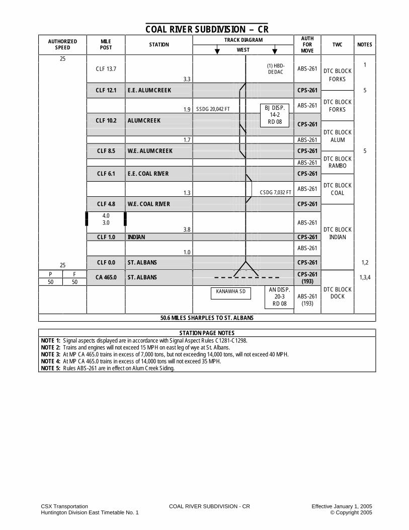
CSX Transportation COAL RIVER SUBDIVISION - CR Effective January 1, 2005 Huntington Division East Timetable No. 1 © Copyright 2005
COAL RIVER SUBDIVISION – CR TRACK DIAGRAM AUTHORIZED
SPEED MILE POST STATION
WEST
AUTH FOR
MOVE TWC NOTES
25
CLF 13.7 (1) HBD-DEDAC DTC BLOCK
1
3.3
ABS-261
FORKS
CLF 12.1 E.E. ALUM CREEK
CPS-261
5
DTC BLOCK 1.9 SSDG 20,042 FT
ABS-261 FORKS
CLF 10.2 ALUM CREEK
CPS-261
DTC BLOCK 1.7 ABS-261 ALUM
CLF 8.5 W.E. ALUM CREEK
CPS-261 5
ABS-261
DTC BLOCK RAMBO
CLF 6.1 E.E. COAL RIVER
CPS-261
DTC BLOCK 1.3 CSDG 7,032 FT
ABS-261 COAL
CLF 4.8 W.E. COAL RIVER
CPS-261
4.0 3.0 ABS-261 3.8 DTC BLOCK CLF 1.0 INDIAN CPS-261 INDIAN 1.0
ABS-261
25 CLF 0.0 ST. ALBANS
CPS-261 1,2
P F
50 50 CA 465.0 ST. ALBANS
CPS-261
(193) 1,3,4
DTC BLOCK ABS-261 DOCK (193)
50.6 MILES SHARPLES TO ST. ALBANS
STATION PAGE NOTES NOTE 1: Signal aspects displayed are in accordance with Signal Aspect Rules C1281-C1298. NOTE 2: Trains and engines will not exceed 15 MPH on east leg of wye at St. Albans. NOTE 3: At MP CA 465.0 trains in excess of 7,000 tons, but not exceeding 14,000 tons, will not exceed 40 MPH. NOTE 4: At MP CA 465.0 trains in excess of 14,000 tons will not exceed 35 MPH. NOTE 5: Rules ABS-261 are in effect on Alum Creek Siding.
KANAWHA SD AN DISP. 20-3
RD 08
BJ DISP. 14-2
RD 08
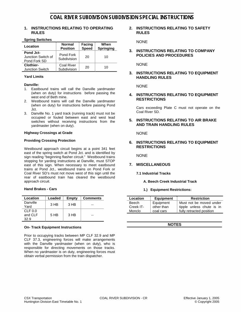
CSX Transportation COAL RIVER SUBDIVISION - CR Effective January 1, 2005 Huntington Division East Timetable No. 1 © Copyright 2005
COAL RIVER SUBDIVISON SUBDIVISION SPECIAL INSTRUCTIONS
1. INSTRUCTIONS RELATING TO OPERATING RULES
Spring Switches
Location Normal Position
Facing Speed
When Springing
Pond Jct- Junction Switch of Pond Fork SD
Pond Fork Subdivision 20 10
Clothier- Junction Switch
Coal River Subdivision 20 10
Yard Limits Danville: 1. Eastbound trains will call the Danville yardmaster
(when on duty) for instructions before passing the west end of Beth mine.
2. Westbound trains will call the Danville yardmaster (when on duty) for instructions before passing Pond Jct.
3. Danville No. 1 yard track (running track) must not be occupied or fouled between east and west lead switches without receiving instructions from the yardmaster (when on duty).
Highway Crossings at Grade Providing Crossing Protection Westbound approach circuit begins at a point 341 feet east of the spring switch at Pond Jct. and is identified by sign reading “beginning flasher circuit.” Westbound trains stopping for yarding instructions at Danville, must STOP east of this sign. When necessary to meet eastbound trains at Pond Jct., westbound trains on Pond Fork or Coal River SD’s must not move west of this sign until the rear of eastbound train has cleared the westbound approach circuit. Hand Brakes - Cars Location Loaded Empty Comments Danville Yard 3 HB 3 HB --
CLF 0.0 and CLF 32.9
5 HB 3 HB --
On- Track Equipment Instructions Prior to occupying tracks between MP CLF 32.9 and MP CLF 37.3, engineering forces will make arrangements with the Danville yardmaster (when on duty), who is responsible for directing movements on those tracks. When no yardmaster is on duty, engineering forces must obtain verbal permission from the train dispatcher.
2. INSTRUCTIONS RELATING TO SAFETY RULES
NONE
3. INSTRUCTIONS RELATING TO COMPANY
POLICIES AND PROCEDURES
NONE 3. INSTRUCTIONS RELATING TO EQUIPMENT HANDLING RULES
NONE 4. INSTRUCTIONS RELATING TO EQIUPMENT RESTRICTIONS
Cars exceeding Plate C must not operate on the Coal River SD.
5. INSTRUCTIONS RELATING TO AIR BRAKE
AND TRAIN HANDLING RULES
NONE 6. INSTRUCTIONS RELATING TO EQUIPMENT
RESTRICTIONS NONE
7. MISCELLANEOUS
7.1 Industrial Tracks
A. Beech Creek Industrial Track 1.) Equipment Restrictions:
Location Equipment Restriction Beech Creek IT-Monclo
Equipment other than coal cars
Must not be moved under tipple unless chute is in fully retracted position
NOTES

CSX Transportation COAL RIVER SUBDIVISION - CR Effective January 1, 2005 Huntington Division East Timetable No. 1 © Copyright 2005
NOTES
NOTES

CSX Transportation COLUMBUS SUBDIVISION - CS Effective January 1, 2005 Huntington Division East Timetable No. 1 © Copyright 2005
COLUMBUS SUBDIVISION - CS TRACK DIAGRAM AUTHORIZED
SPEED MILE POST STATION
WEST
AUTH FOR
MOVE TWC NOTE
F P01 P01 P02
BUCKEYE 6 THIRD RAIL 30 CK 4.5 BUCKEYE SIX
1,2,3
0.4 1 2
ABS-261 (193)
CK 4.2 HIGH STREET CPS-261
(193) YL
CK 3.0 1.5 0.4
ABS-261 (193)
CK 2.1 CP RIVER
CPS-261 (193)
CK 1.7 0.9 TTB ABS-261 30 SOCITO
CK 1.1 CONN. (193) 25
NS RR 30
CK 1.0 LM CABIN
CPS-261 (193)
5
CK 0.9 0.1 TTB ABS-261 (193)
CK 0.8 WEST LM CABIN
CPS-261 (193)
0.4 ABS-261 (193)
CK 0.5 CD 0.5 E.E. HV JCT
CPS-261
(193) 4
MUD TRACK ABS-261 0.3 (193) 4
CD 0.8 HV JCT. NS
CPS-261 (193)
SE
E N
OT
E 4
CD 1.0
TTB
30 50
CD 1.2 4.2
3.0
ABS-261 (193)
YL
4.0 MP FOUR
CPS-261
CD 5.3 2.3 (1) HBD-DEDAC ABS-261
DTC BLOCK BUCKEYE
CD 7.6 E.E. LINWORTH
CPS-261
13
DTC BLOCK 1.6 SSDG 7,275 FT.
ABS-261 WORTH
CD 9.2 W.E. LINWORTH
CPS-261
13
7.3 DTC BLOCK CD 16.5 POWELL WYE ABS-261 POWELL
50 1.9 1 2 40
TURNOUT CD 18.4 HYATTS
CPS-261
ABS-261 50
CD 20.3 (1) HBD-DEDAC 50 ABS-261
DTC BLOCK DELA
TO MASON YARD
TO NEW YARD
YARD A MIDDLE
CR DISP. 14-1
RD 08
COLUMBUS LINE SD

CSX Transportation COLUMBUS SUBDIVISION - CS Effective January 1, 2005 Huntington Division East Timetable No. 1 © Copyright 2005
COLUMBUS SUBDIVISION - CS TRACK DIAGRAM AUTHORIZED
SPEED MILE POST STATION
WEST
AUTH FOR
MOVE TWC NOTES
50 ABS-261
1,2,3
3.5
CD 21.9 E.E. DELAWARE
CPS-261
13
SSDG 7,924 FT. DTC BLOCK 1.5 ABS-261 DELA
CD 23.4 W.E. DELAWARE
CPS-261 13
50 1.8 ABS-261
DTC BLOCK CABIN
40 TURNOUT CD 25.2 RW CABIN
CPS-261
50 DTC BLOCK
5.7 1 2 ABS-261
MEREDITH
CD 30.9 MEREDITH
CPS-261
4.9 CD 35.8 PROSPECT DTC BLOCK CD 38.7 (1) HBD-DEDAC
ABS-261 PRO
4.8
CD 40.6 OWENS
CPS-261
50 1 2 DTC BLOCK 30 CD 43.8 3.9
ABS-261 OWENS
CD 44.5 MA CABIN
CPS-261
30 1.1 ABS-261 25
OVER DIAMOND CD 45.6 AC CABIN (X)(R)
CPS-261
30 0.6 ABS-261 6,7
CD 46.2 MARION CONNECTION
CPS-261
0.3 30 CD 46.5 MD CABIN
ABS-261 DTC BLOCK
50 ACTION
CD 46.8 E.E. MD SIDING
CPS-261
13
SSDG 6,988 FT. ABS-261
CD 48.1 W.E. MD SIDING
CPS-261
13
ABS-261
50 3.4 1 2 40
TURNOUT CD 49.9 ACTON
CPS-261
50 ABS-261 DTC BLOCK MORRAL
50 ABS-261 1,2,3
CR DISP. 14-1
RD 08
MT. VICTORY SD
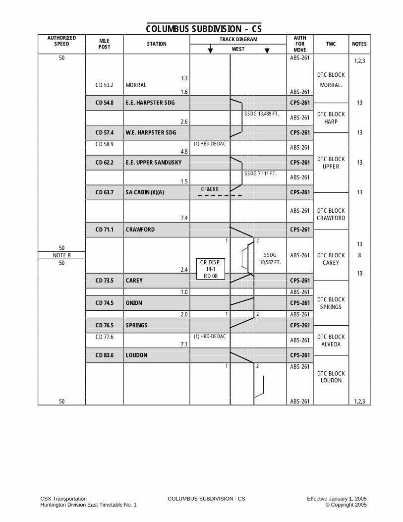
CSX Transportation COLUMBUS SUBDIVISION - CS Effective January 1, 2005 Huntington Division East Timetable No. 1 © Copyright 2005
COLUMBUS SUBDIVISION - CS TRACK DIAGRAM AUTHORIZED
SPEED MILE POST STATION
WEST
AUTH FOR
MOVE TWC NOTES
ABS-261 50
1,2,3
3.3 DTC BLOCK
CD 53.2 MORRAL MORRAL. 1.6 ABS-261
CD 54.8 E.E. HARPSTER SDG
CPS-261
13
SSDG 13,489 FT. DTC BLOCK 2.6
ABS-261 HARP
CD 57.4 W.E. HARPSTER SDG
CPS-261
13
CD 58.9 (1) HBD-DEDAC 4.8
ABS-261
DTC BLOCK
CD 62.2 E.E. UPPER SANDUSKY
CPS-261 UPPER
13
SSDG 7,111 FT. 1.5
ABS-261
CF&ERR
CD 63.7 SA CABIN (X)(A)
CPS-261
13
ABS-261 DTC BLOCK 7.4 CRAWFORD
CD 71.1 CRAWFORD
CPS-261
1 2 50
13
NOTE 8 SSDG ABS-261 DTC BLOCK 8 50 10,587 FT. CAREY
2.4
13
CD 73.5 CAREY
CPS-261
1.0 ABS-261 DTC BLOCK
CD 74.5 ONION
CPS-261 SPRINGS
2.0 1 2 ABS-261
CD 76.5 SPRINGS
CPS-261
CD 77.6 (1) HBD-DEDAC DTC BLOCK 7.1
ABS-261 ALVEDA
CD 83.6 LOUDON
CPS-261
1 2 ABS-261 DTC BLOCK LOUDON
50 ABS-261 1,2,3
CR DISP. 14-1
RD 08
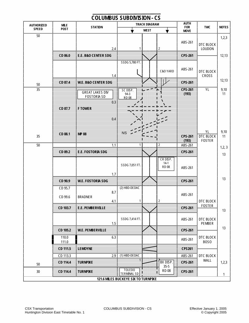
CSX Transportation COLUMBUS SUBDIVISION - CS Effective January 1, 2005 Huntington Division East Timetable No. 1 © Copyright 2005
COLUMBUS SUBDIVISION - CS TRACK DIAGRAM AUTHORIZED
SPEED MILE POST STATION
WEST
AUTH FOR
MOVE TWC NOTES
50
1,2,3
ABS-261
2.4 1 2 DTC BLOCK
LOUDON
CD 86.0 E.E. B&O CENTER SDG
CPS-261
12,13
SSDG 5,780 FT. C&O YARD ABS-261
DTC BLOCK 1.4 CROSS
12,13 50 CD 87.4 W.E. B&O CENTER SDG
CPS-261
CPS-261 YL 9,10 35 (193) 11
0.3 CD 87.7 F TOWER 0.4 YL 9,10
35 CD 88.1 MP 88 CPS-261 DTC BLOCK 11
(193) FOSTER 50 1.1 1 2 ABS-261
1,2, 3
CD 89.2 E.E. FOSTORIA SDG
CPS-261
13
SSDG 7,051 FT.
ABS-261
1.7 13
CD 90.9 W.E. FOSTORIA SDG
CPS-261
CD 95.7 (2) HBD-DEDAC 8.7 CD 99.6 BRADNER ABS-261
4.1 1 2 DTC BLOCK FOSTER
CD 103.7 E.E. PEMBERVILLE
CPS-261 13
SSDG 7,414 FT. ABS-261 DTC BLOCK 1.5 PEMBER 13
CD 105.2 W.E. PEMBERVILLE
CPS-261
110.0 6.3 DTC BLOCK 111.0
ABS-261 BOSO
CD 111.5 LEMOYNE
CPS261
CD 113.3 2.9 (1) HBD-DEDAC ABS-261 DTC BLOCK 1 2 WALL
50 CD 114.4 TURNPIKE CPS-261
1,2,3
30 CD 114.4 TURNPIKE
CPS-261 1 121.6 MILES BUCKEYE SIX TO TURNPIKE
SC DISP. 94-3
RD 08
GREAT LAKES DIV FOSTORIA SD
NS
CR DISP. 14-1
RD 08
BX DISP. 35-5
RD 08 TOLEDO TERMINAL SD

CSX Transportation COLUMBUS SUBDIVISION - CS Effective January 1, 2005 Huntington Division East Timetable No. 1 © Copyright 2005
STATION PAGE NOTES
NOTE 1: Signal aspects displayed on the Columbus SD between MP CK 4.2 and MP CD 114.4 are in accordance with Signal Aspect Rules C1281 –C1298. NOTE 2: Between MP CK 4.5 and MP CD 114.4, trains in excess of 10,000 tons, but not exceeding 20,000 tons will not exceed 40 MPH. NOTE 3: Between MP CK 4.5 and MP CD 114.4, trains in excess of 20,000 tons will not exceed 35 MPH. NOTE 4: Eastbound trains using No. 2 main between MP CD 1.0 and MP CK 0.5 must not exceed 10 MPH. This restriction applies to the head end
only. NOTE 5: Trains and engines operating on the Scioto Connection track at LM Cabin will not exceed 20 MPH. NOTE 6: Trains using the Marion connection track will not exceed 10 MPH. NOTE 7: Before occupying the Marion connection track, all trains must secure permission from the IE train dispatcher located in Indianapolis, Indiana. NOTE 8: Trains or engines must not exceed 20 MPH when operating in the Carey Center siding. NOTE 9: Signal aspects displayed on the Fostoria SD between MP BI 36.1 and BI 37.0 are in accordance with Signal Aspect Rules 1281-1298. NOTE 10: Between MP CD 88.4 and F Tower MP CD 87.7 eastbound trains or engines operating in accordance with a signal indication requiring
medium speed will not exceed 20 MPH. NOTE 11: Trains or engines will not exceed 10 MPH while operating on wye tracks in Fostoria. NOTE 12: Trains or engines must not exceed 25 MPH when entering or departing B&O Center Siding MP CD 86.0 and MP CD 87.4 NOTE 13: Rules ABS-261 are in effect on all sidings.
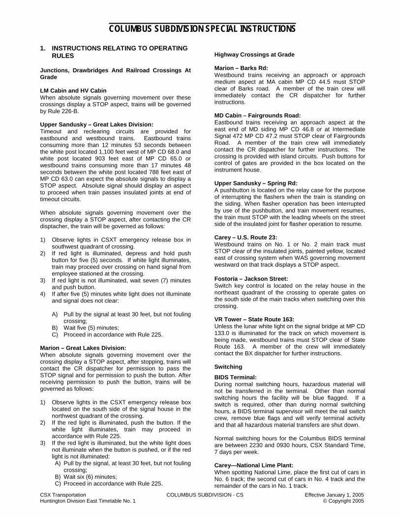
CSX Transportation COLUMBUS SUBDIVISION - CS Effective January 1, 2005 Huntington Division East Timetable No. 1 © Copyright 2005
COLUMBUS SUBDIVISION SPECIAL INSTRUCTIONS
1. INSTRUCTIONS RELATING TO OPERATING RULES Junctions, Drawbridges And Railroad Crossings At Grade LM Cabin and HV Cabin When absolute signals governing movement over these crossings display a STOP aspect, trains will be governed by Rule 226-B. Upper Sandusky – Great Lakes Division: Timeout and reclearing circuits are provided for eastbound and westbound trains. Eastbound trains consuming more than 12 minutes 53 seconds between the white post located 1,100 feet west of MP CD 68.0 and white post located 903 feet east of MP CD 65.0 or westbound trains consuming more than 17 minutes 48 seconds between the white post located 788 feet east of MP CD 63.0 can expect the absolute signals to display a STOP aspect. Absolute signal should display an aspect to proceed when train passes insulated joints at end of timeout circuits.
When absolute signals governing movement over the crossing display a STOP aspect, after contacting the CR disptacher, the train will be governed as follows:
1) Observe lights in CSXT emergency release box in
southwest quadrant of crossing. 2) If red light is illuminated, depress and hold push
button for five (5) seconds. If white light illuminates, train may proceed over crossing on hand signal from employee stationed at the crossing.
3) If red light is not illuminated, wait seven (7) minutes and push button.
4) If after five (5) minutes white light does not illuminate and signal does not clear: A) Pull by the signal at least 30 feet, but not fouling
crossing; B) Wait five (5) minutes; C) Proceed in accordance with Rule 225.
Marion – Great Lakes Division: When absolute signals governing movement over the crossing display a STOP aspect, after stopping, trains will contact the CR dispatcher for permission to pass the STOP signal and for permission to push the button. After receiving permission to push the button, trains will be governed as follows:
1) Observe lights in the CSXT emergency release box
located on the south side of the signal house in the northwest quadrant of the crossing.
2) If the red light is illuminated, push the button. If the white light illuminates, train may proceed in accordance with Rule 225.
3) If the red light is illuminated, but the white light does not illuminate when the button is pushed, or if the red light is not illuminated: A) Pull by the signal, at least 30 feet, but not fouling
crossing; B) Wait six (6) minutes; C) Proceed in accordance with Rule 225.
Highway Crossings at Grade Marion – Barks Rd: Westbound trains receiving an approach or approach medium aspect at MA cabin MP CD 44.5 must STOP clear of Barks road. A member of the train crew will immediately contact the CR dispatcher for further instructions. MD Cabin – Fairgrounds Road: Eastbound trains receiving an approach aspect at the east end of MD siding MP CD 46.8 or at Intermediate Signal 472 MP CD 47.2 must STOP clear of Fairgrounds Road. A member of the train crew will immediately contact the CR dispatcher for further instructions. The crossing is provided with island circuits. Push buttons for control of gates are provided in the box located on the instrument house. Upper Sandusky – Spring Rd: A pushbutton is located on the relay case for the purpose of interrupting the flashers when the train is standing on the siding. When flasher operation has been interrupted by use of the pushbutton, and train movement resumes, the train must STOP with the leading wheels on the street side of the insulated joint for flasher operation to resume. Carey – U.S. Route 23: Westbound trains on No. 1 or No. 2 main track must STOP clear of the insulated joints, painted yellow, located east of crossing system when WAS governing movement westward on that track displays a STOP aspect. Fostoria – Jackson Street: Switch key control is located on the relay house in the northeast quadrant of the crossing to operate gates on the south side of the main tracks when switching over this crossing. VR Tower – State Route 163: Unless the lunar white light on the signal bridge at MP CD 133.0 is illuminated for the track on which movement is being made, westbound trains must STOP clear of State Route 163. A member of the crew will immediately contact the BX dispatcher for further instructions. Switching
BIDS Terminal: During normal switching hours, hazardous material will not be transferred in the terminal. Other than normal switching hours the facility will be blue flagged. If a switch is required, other than during normal switching hours, a BIDS terminal supervisor will meet the rail switch crew, remove blue flags and will verify terminal activity and that all hazardous material transfers are shut down. Normal switching hours for the Columbus BIDS terminal are between 2230 and 0930 hours, CSX Standard Time, 7 days per week. Carey—National Lime Plant: When spotting National Lime, place the first cut of cars in No. 6 track; the second cut of cars in No. 4 track and the remainder of the cars in No. 1 track.
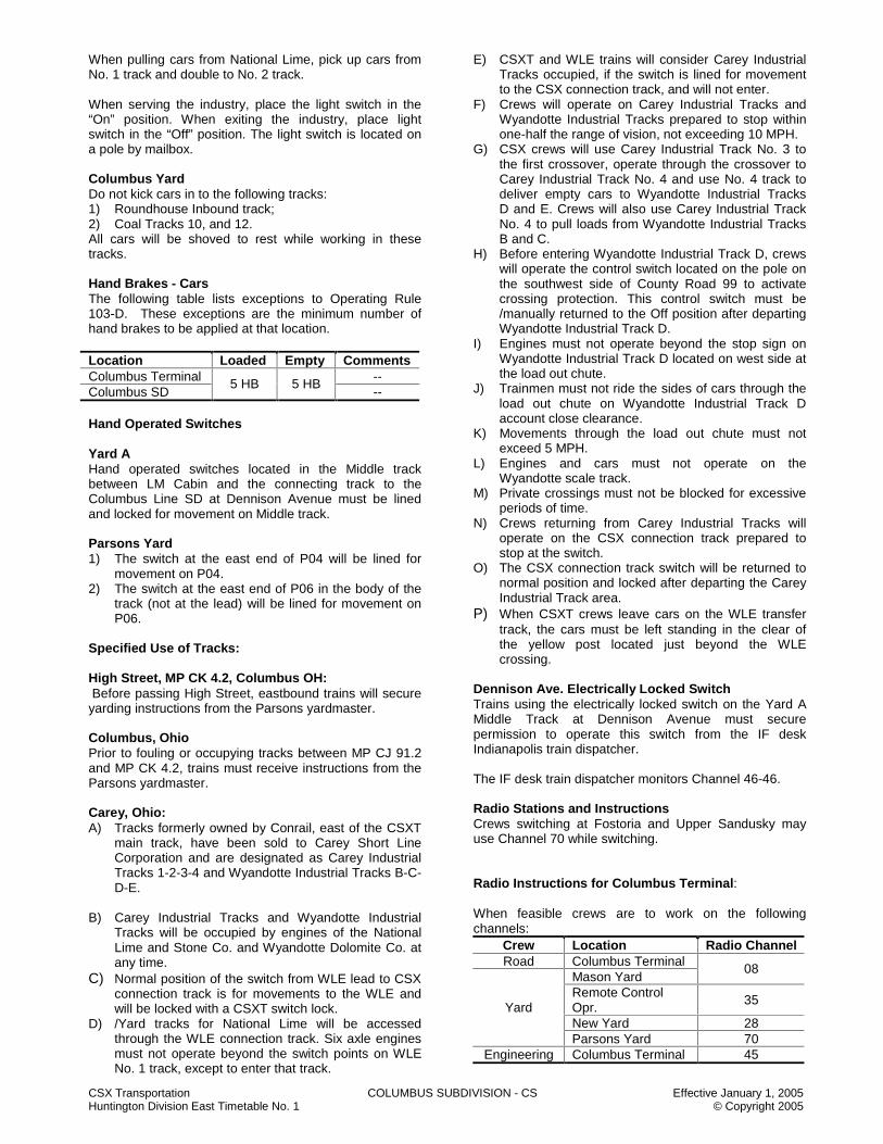
CSX Transportation COLUMBUS SUBDIVISION - CS Effective January 1, 2005 Huntington Division East Timetable No. 1 © Copyright 2005
When pulling cars from National Lime, pick up cars from No. 1 track and double to No. 2 track. When serving the industry, place the light switch in the “On” position. When exiting the industry, place light switch in the “Off” position. The light switch is located on a pole by mailbox. Columbus Yard Do not kick cars in to the following tracks: 1) Roundhouse Inbound track; 2) Coal Tracks 10, and 12. All cars will be shoved to rest while working in these tracks. Hand Brakes - Cars The following table lists exceptions to Operating Rule 103-D. These exceptions are the minimum number of hand brakes to be applied at that location. Location Loaded Empty Comments Columbus Terminal -- Columbus SD
5 HB 5 HB --
Hand Operated Switches Yard A Hand operated switches located in the Middle track between LM Cabin and the connecting track to the Columbus Line SD at Dennison Avenue must be lined and locked for movement on Middle track. Parsons Yard 1) The switch at the east end of P04 will be lined for
movement on P04. 2) The switch at the east end of P06 in the body of the
track (not at the lead) will be lined for movement on P06.
Specified Use of Tracks: High Street, MP CK 4.2, Columbus OH: Before passing High Street, eastbound trains will secure yarding instructions from the Parsons yardmaster. Columbus, Ohio Prior to fouling or occupying tracks between MP CJ 91.2 and MP CK 4.2, trains must receive instructions from the Parsons yardmaster. Carey, Ohio: A) Tracks formerly owned by Conrail, east of the CSXT
main track, have been sold to Carey Short Line Corporation and are designated as Carey Industrial Tracks 1-2-3-4 and Wyandotte Industrial Tracks B-C-D-E.
B) Carey Industrial Tracks and Wyandotte Industrial
Tracks will be occupied by engines of the National Lime and Stone Co. and Wyandotte Dolomite Co. at any time.
C) Normal position of the switch from WLE lead to CSX connection track is for movements to the WLE and will be locked with a CSXT switch lock.
D) /Yard tracks for National Lime will be accessed through the WLE connection track. Six axle engines must not operate beyond the switch points on WLE No. 1 track, except to enter that track.
E) CSXT and WLE trains will consider Carey Industrial Tracks occupied, if the switch is lined for movement to the CSX connection track, and will not enter.
F) Crews will operate on Carey Industrial Tracks and Wyandotte Industrial Tracks prepared to stop within one-half the range of vision, not exceeding 10 MPH.
G) CSX crews will use Carey Industrial Track No. 3 to the first crossover, operate through the crossover to Carey Industrial Track No. 4 and use No. 4 track to deliver empty cars to Wyandotte Industrial Tracks D and E. Crews will also use Carey Industrial Track No. 4 to pull loads from Wyandotte Industrial Tracks B and C.
H) Before entering Wyandotte Industrial Track D, crews will operate the control switch located on the pole on the southwest side of County Road 99 to activate crossing protection. This control switch must be /manually returned to the Off position after departing Wyandotte Industrial Track D.
I) Engines must not operate beyond the stop sign on Wyandotte Industrial Track D located on west side at the load out chute.
J) Trainmen must not ride the sides of cars through the load out chute on Wyandotte Industrial Track D account close clearance.
K) Movements through the load out chute must not exceed 5 MPH.
L) Engines and cars must not operate on the Wyandotte scale track.
M) Private crossings must not be blocked for excessive periods of time.
N) Crews returning from Carey Industrial Tracks will operate on the CSX connection track prepared to stop at the switch.
O) The CSX connection track switch will be returned to normal position and locked after departing the Carey Industrial Track area.
P) When CSXT crews leave cars on the WLE transfer track, the cars must be left standing in the clear of the yellow post located just beyond the WLE crossing.
Dennison Ave. Electrically Locked Switch Trains using the electrically locked switch on the Yard A Middle Track at Dennison Avenue must secure permission to operate this switch from the IF desk Indianapolis train dispatcher. The IF desk train dispatcher monitors Channel 46-46.
Radio Stations and Instructions Crews switching at Fostoria and Upper Sandusky may use Channel 70 while switching.
Radio Instructions for Columbus Terminal: When feasible crews are to work on the following channels:
Crew Location Radio Channel Road Columbus Terminal
Mason Yard 08
Remote Control Opr.
35
New Yard 28 Yard
Parsons Yard 70 Engineering Columbus Terminal 45

CSX Transportation COLUMBUS SUBDIVISION - CS Effective January 1, 2005 Huntington Division East Timetable No. 1 © Copyright 2005
Crews will use Channel 08 when contacting the Parsons yardmaster for instructions. Prior to going from one yard to another, crews must contact the Parsons yardmaster. Parsons yardmaster monitors both Channel 08 and Channel 35. Engineering Forces Prior to fouling or occupying tracks between MP CJ 91.2 and MP CK 4.2, engineering forces will make arrangements with the Parsons yardmaster who is responsible for directing movements on these tracks. Engineering forces must report to the Parsons yardmaster when clear of these tracks. 2. INSTRUCTIONS RELATING TO SAFETY
RULES Close Clearance: Employees are prohibited from riding the side of equipment at the following locations:
1) Between the Back Lead and N08 2) Between N09 and N10 3) Between N13 and N14 4) Between N14 and N15 5) Between N15 and N16 6) Between N17 and N18 7) Sunny Farms – Louden, OH
3. INSTRUCTIONS RELATING TO COMPANY
POLICIES AND PROCEDURES NONE 4. INSTRUCTIONS RELATING TO EQUIPMENT HANDLING RULES Moving Clearance Implicated Shipments Columbus Terminal CH Cabin to CK 4.5 Control - CSX Chief/Dispatcher Jacksonville and General Yardmaster/Yardmaster Parsons 1. The Parsons yardmaster will review all Hi-Wide
messages with crews during job briefings. 2. The Parsons yardmaster will ensure all conflicting
movements are stopped before High-Wide shipments are moved within the yard.
3. Through Hi-Wide movements between CH Cabin and CK 4.5 will use the Hill Track and P01 or P02 tracks.
4. Yard Operations a) Place in Mason Yard with adjacent tracks clear. b) Place in Parsons Yard with adjacent tracks
clear. c) Place in New Yard with adjacent tracks clear.
See Close Clearance Instruction in Section 5, Rule 2151.
5. Store/Hold in Coal Tracks 10 and 12. Columbus Subdivision CK 4.5 to CD 114.4 Control – CSX Chief/Dispatcher Jacksonville and Operator/Yardmaster Fostoria, Ohio 1) Through Traffic will use No. 1-2 yard main tracks
2) Storage Cars will use No. 1 and No. 2 yard tracks – Store/Hold in Engine Track
5. INSTRUCTIONS RELATING TO AIR BRAKE AND TRAIN HANDLING RULES Calendar Day Inspection for Yard Locomotives at Columbus Engineers/Remote Control Operators working 3rd shift yard assignments (2330 hours) at Parsons Yard, Columbus, OH, will perform the calendar day on their locomotives at the end of their tour of duty. These inspections will also include the slug unit. A separate 5001A is required for the slug unit. The hours of service law will not be exceeded to perform this inspection. All defects found must be reported to the yardmaster and mechanical desk prior to going off duty. If the calendar day inspection has not been performed, because of locomotives not being used on third shift, etc., the engineer/remote control operator on the next shift the locomotives are used is responsible for completing this inspection. It is mandatory that each yard locomotive and slug be inspected each calendar day. Air Brake Test Certificate Conductors or engineers on inbound trains arriving Parsons Yard, must contact Parsons Yardmaster to ascertain instructions concerning air brake test certificate for their train. 6. INSTRUCTIONS RELATING TO EQUIPMENT RESTRICTIONS
Location Equipment Restriction
Parsons Yard
DEEX 1001 through DEEX
4143 when loaded
Must use tracks P01 or P02
Rising Sun—S&D Applications MP CD 95.3 Airco MP CD 86.5 Walton MP CD 77.3 Mueller Plastics MP CD 63.9 Delaware Industrial Park
Six-Axle engines
Must Not Operate

CSX Transportation COLUMBUS SUBDIVISION - CS Effective January 1, 2005 Huntington Division East Timetable No. 1 © Copyright 2005
7. MISCELLANEOUS 7.1 Delaware—Autochem Company:
A safety switch to deactivate the blower system and activate a blue light and warning bell on the Pennwalt crossing is located in a metal box on the northwest corner of the building on the south side of the Autochem Company track. Crews serving this plant will, before passing the safety switch location, place the switch in the “On” position. After serving the plant, the switch must be returned to the “Off” position.
7.2 Delaware Industrial Park.
NOTES
NOTES

CSX Transportation COLUMBUS SUBDIVISION - CS Effective January 1, 2005 Huntington Division East Timetable No. 1 © Copyright 2005
NOTES
NOTES

CSX Transportation COLUMBUS LINE SUBDIVISION - CY Effective January 1, 2005 Huntington Division EastTimetable No. 1 © Copyright 2005
COLUMBUS LINE SUBDIVISION - CY TRACK DIAGRAM AUTHORIZED
SPEED MILE POST STATION
WEST
AUTH FOR
MOVE TWC NOTES
IM F 6 30 30
ABS-261
CPS-261
30 30 QI 80.3 CP 80
IM F 1,2,6 60 50 QE 85.0 (2) HBD-DED 4.9 QE 85.2 ST. JAMES ABS-261 2.0 QE 87.2 SIMS EDISON IT 5.6 3
QE 92.8 CP 92
CPS-261
SSDG 5,314 FT. 1.1
ABS-261
QE 93.9 CP 93
CPS-261 3
10.5 QE 104.4 ASHLEY ABS-261
QE 108.3 LEONARDSBURG (2) HBD-DED HWD-HCD
2.8 4,5
QE 111.1 CP 111
CPS-261
SSDG 6.0 MILES ABS-261 6.0
60 50 50 40
QE 117.1 CP 117
CPS-261 4,5
7.9 QE 125.0 LEWIS CENTER (2) HBD-DED BUSCH LEAD ABS-261 QE 128.6 4.0 3
QE 129.0 CP 129
CPS-261
0.8 SSDG 4,280 FT. ABS-261 7 40
QE 129.8 CP 130
CPS-261
3 QE 130.2
ABS-261 50
QE 131.0
40
40 ABS-261 2
IF DISP. 46-7#
4 CLICKS
IF DISP. 46-3#
3 CLICKS
GREENWICH SD
NS

CSX Transportation COLUMBUS LINE SUBDIVISION - CY Effective January 1, 2005 Huntington Division EastTimetable No. 1 © Copyright 2005
COLUMBUS LINE SUBDIVISION - CY TRACK DIAGRAM AUTHORIZED
SPEED MILE POST STATION
WEST
AUTH FOR
MOVE TWC NOTES
IM F 40 40
6
ABS-261 2
131.0
40 50
132.0
2.4 QE 133.5 CP 133 CPS-261 QE 133.7 (2) DED ABS-261 0.8 QE 134.3 CLINTONVILLE QE 135.0
50
QE 135.7 40
QE 135.8
2.5 ABS-261
40 40
30
30
QE 136.8 CP 136 CPS-261
ABS-261
30 30 QE 138.0 2 25 25 QEB 0.0
CP 138
CPS-261 8
25 25 0.4
QEB 0.4 DENNISON AVE ABS-261
0.6 TO YARD A
25 25
QEB 1.0 CP HOCKING
CPS-261 1
58.7 MILES CP 80 TO CP HOCKING
STATION PAGE NOTES NOTE 1: All signals are CR-1277 to CR-1294a. NOTE 2: Loaded unit grain and mineral trains or mixed freight trains having 30 or more loaded grain or mineral cars must not exceed 40 MPH. NOTE 3: Trains and engines operating in non-controlled sidings will operate at restricted speed not exceeding 10 MPH. NOTE 4: Trains and engines operating in controlled sidings will not exceed 10 MPH except trains and engines operating in the Delaware controlled
siding will not exceed 25 MPH. NOTE 5: Rule ABS-261 are in effect on all sidings. NOTE 6: Speed column designators: IM = Intermodal (Trailer Van – TV) Train NOTE 7: Trains and engines must not exceed 40 MPH through CP 130. NOTE 8: Trains and engines must not exceed 25 MPH through CP 138.
NS RR
IF DISP. 46-7#
4 CLICKS
NS WEBER CONNECTION
OC RR
COLUMBUS SD
NS CINCINNATI
LINE

CSX Transportation COLUMBUS LINE SUBDIVISION - CY Effective January 1, 2005 Huntington Division EastTimetable No. 1 © Copyright 2005
COLUMBUS LINE SUBDIVISION SPECIAL INSTRUCTIONS 1. INSTRUCTIONS RELATING TO OPERATING
RULES
Additional Instructions Dispatcher controlling power switches within the working limits of a Form W must line switches for movements within the working limits and must apply blocking devices to the controls of these switches. The blocking devices must not be removed without the permission of the employee in charge. Before displaying a signal for a train to divert into the work limits, the dispatcher must confirm with the employee in charge that the train has permission to enter the working limits. Employee Duties Flagman must not allow equipment to obstruct a main track or siding without permission from the train dispatcher. Before authorizing flagman to allow equipment to obstruct the track, the train dispatcher must determine that no movements are within or authorized to occupy the track segment to be obstructed and that blocking devices are applied to prevent any conflicting movement. Permission must include: 1. Employee (Flagman) Name 2. Track Designation 3. Track Limits (Between/At Location) 4. Time Limits (Expected Clear Time) Employee receiving permission must repeat the information received and the train dispatcher must confirm the repeat before permission to obstruct the track becomes effective.
2. INSTRUCTIONS RELATING TO SAFETY RULES
NONE
3. INSTRUCTIONS RELATING TO COMPANY
POLICIES AND PROCEDURES
NONE 4. INSTRUCTIONS RELATING TO EQUIPMENT
HANDLING RULES
NONE 5. INSTRUCTIONS RELATING TO AIR BRAKE
AND TRAIN HANDLING RULES
NONE
6. INSTRUCTIONS RELATING TO EQUIPMENT RESTRICTIONS
Weight restrictions 315,000 lbs. authorized
7. MISCELLANEOUS 7.1 Industrial Tracks A) Edison IT
1. Edison industrial track extends between MP QEE 87.3 and MP QEE 89.0
2. Edison industrial track is designated as excepted track between MP 0.4 and MP 4.0.
NOTES

CSX Transportation COLUMBUS LINE SUBDIVISION - CY Effective January 1, 2005 Huntington Division EastTimetable No. 1 © Copyright 2005
NOTES
NOTES

CSX Transportation COWEN SUBDIVISION - CJ Effective January 1, 2005 Huntington Division East Timetable No. 1 © Copyright 2005
COWEN SUBDIVISION – CJ TRACK DIAGRAM
AUTHORIZED SPEED
MILE POST STATION
WEST
AUTH FOR
MOVE TWC NOTES
ABS-261 20 BA 281.6 BERKELEY RUN JCT. (193) YL 7
25 CPS-261 1
BUC 0.0 BERKELEY RUN JCT (193) YL
ABS-261 (193)
BUC 0.3
3.0 4.6 ABS-261
4.0
BUC 4.6 EAST KNIGHT
CPS-261
2,8
0.9 SSDG 4,100 FT. ABS-261
BUC 5.5 WEST KNIGHT
CPS-261
2,8
BUC 5.6 DTC BLOCK BUC 5.7
KNIGHT TUNNEL ABS-261 BERRY
BUC 8.5 BUC 8.9
LANE TUNNEL
BUC 9.7 EAST BERRYBURG CPS-261 2 1.4 SSDG 7,485 FT. ABS-261
BUC 11.1 BERRYBURG JCT CPS-261 2 25 ABS-261 BUC 13.4
DTC BLOCK 20
PHIL BUC 14.6
25
BUC 18.2
7.6 20
25
BUC 18.4 ABS-261
BUC 18.7 EAST TYGART CPS-261 3 0.9 CSDG 4,600 FT. ABS-261
BUC 19.6 TYGART JCT CPS-261 25
BUC 21.0
20 ABS-261
25 BUC 23.4
4.1
BUC 23.7 CENTURY JCT.
CPS-261
25 ABS-261 BUC 26.3
20
7.9 25 BUC 26.5
DTC BLOCK PHIL
BUC 31.1 ABS-261
BUC 31.6 EAST SMITH SUMMIT CPS-261 0.5 CSDG 7,500 FT. ABS-261 3 BUC 32.1 WEST SMITH SUMMIT CPS-261
25 ABS-261
BUC 35.4 DTC BLOCK
15 BUC 36.2 BUCKHANNON PICK
20 BUC 36.5
7.2 BUC 37.8 4,100 FT BUC 38.1 UPSHUR
20 BUC 38.6 ABS-261
MOUNTAIN SD
CI DISP. 14-2
RD – 08 GR – 08 YD - 28
W. VA C. RR
4.2
BERRYBURG IT
CENTURY IT
CI DISP. 14-5
RD 08

CSX Transportation COWEN SUBDIVISION - CJ Effective January 1, 2005 Huntington Division East Timetable No. 1 © Copyright 2005
COWEN SUBDIVISION - CJ TRACK DIAGRAM AUTHORIZED
SPEED MILE POST STATION
WEST
AUTH FOR
MOVE TWC NOTES
20 25
BUC 38.7
ABS-261
BUC 39.3 CAPITAL MINE CPS-261 2.6 ABS-261 DTC BLOCK
25 PICK BUC 41.9 HAMPTON JCT.
CPS-261
BUC 42.0 HAMPTON TUNNEL 15
ABS-261 1
BUC 42.1 DTC BLOCK SIGN HAMPTON TWC-DTC 25
BUC 42.6
20
25 BUC 43.2
9.8 BUC 44.2 SIGNAL 442 DTC BLOCK 9 BUC 48.4 ADA BUC 48.5
ABBOTT TUNNEL
BUC 51.0 BUC 51.1
JONES TUNNEL
BUC 51.7 EAST FRENCHTON 52.0 FRENCHTON 0.6 52.3
52.3 DTC BLOCK SIGN
WEST FRENCHTON 53.0
25 DTC BLOCK BUC 53.6
5.2 FRENCH 10 FRENCHTON TUNNEL
ABTH 5559
25
BUC 53.8 BUC 53.9
BUC 56.8 56.8
BUC 57.5 DTC BLOCK SIGN EAST CRAWFORD
BUC 57.9 CRAWFORD 0.9 5,512 FT
BUC 58.4 WEST CRAWFORD ss BUC 61.3 61.3 BUC 62.2 BUC 62.6
JACKSONVILLE TUNNEL
25 DTC BLOCK BUC 63.2
ABTH 5559 CHAPMAN 10
25
BUC 63.4 14.6
BUC 64.0 DTC BLOCK SIGN BUC 65.8 65.8
TWC-DTC DTC BLOCK
BATO
BUC 72.1 DTC BLOCK SIGN 193 YL
25
BUC 72.7
15 BUC 73.0 BURNSVILLE JCT. 4,5
BUC 73.1 0.5
10
15 BUC 73.3
BUC 73.5 EAST BURNSVILLE
BUC 73.7 BURNSVILLE
15 193 YL 20
BUC 74.6 DTC BLOCK SIGN WEST BURNSVILLE DTC BLOCK
TWC-DTC
GEM
PICKENS SD
2,850 FT.
ELK IT
5,460 FT 1.1

CSX Transportation COWEN SUBDIVISION - CJ Effective January 1, 2005 Huntington Division East Timetable No. 1 © Copyright 2005
COWEN SUBDIVISION – CJ TRACK DIAGRAM AUTHORIZED
SPEED MILE POST STATION
WEST
AUTH FOR
MOVE TWC NOTES
TWC-DTC DTC BLOCK 20 GEM
BUC 81.0 DTC BLOCK SIGN 7.3
BUC 81.9 EAST HEATERS 20 DTC BLOCK 25
BUC 82.0 HEATERS 0.2 COG
BUC 82.1 WEST HEATERS
BUC 82.5 DTC BLOCK SIGN
BUC 87.6 MORRISON TUNNEL BUC 92.3 BUC 92.4
ELK TUNNEL DTC BLOCK
94.0 13.3 SHAVE 95.0
BUC 95.4 DTC BLOCK SIGN EAST CENTRALIA
BUC 96.2 CENTRALIA 1.0 5,250 FT BUC 96.4 WEST CENTRALIA BUC 97.3 97.3
25 25
BUC 101.5 DTC BLOCK
6
ABTH 5559 WOLFE
20 M
PH
East
boun
d H
ead-
end
only
0.9
25 BUC 105.0
BUC 105.2 105.2
BUC 105.4 DTC BLOCK SIGN EAST ERBACON
1.0 DTC BLOCK BUC 106.4 WEST ERBACON ERB
BUC 106.5 DTC BLOCK SIGN ERBACON
BUC 108.6 108.6
25
25 BUC 109.0
DTC BLOCK
110.0 ARCOLA
111.0 10.1
TWC-DTC
BUC 115.0 DTC BLOCK SIGN
193 YL BUC 115.6 115.6
BUC 116.5 WN TOWER
4,5
25
20 M
PH E
ASTB
OU
ND
H
EAD
-EN
D O
NLY
193 YL
BUC 119.0 COWEN END OF MAIN TRACK 96
116.3 MILES BERKELEY JCT. TO END OF TRACK COWEN
BROOKS RUN IT
WEYERHAUSER IT
5,100 FT
WILLIAMS IT
ABTH 5559
2.5
CSX Transportation COWEN SUBDIVISION - CJ Effective January 1, 2005 Huntington Division East Timetable No. 1 © Copyright 2005
STATION PAGE NOTES NOTE 1: All signals are Signal Rules 1281 – 1298. NOTE 2: Rules ABS-261 are in effect on the signaled sidings at Knight and Berryburg Jct. NOTE 3: Rule 96 is in effect on the controlled sidings at Tygart and Smith Summit. NOTE 4: Permission must be obtained from the CI Train Dispatcher before entering Main Track between BUC 72.1 and BUC 74.6 and also between
BUC 115.0 and BUC 119.0. NOTE 5: On-track equipment instructions – Main Track between BUC 72.1 and BUC 74.6 and between BUC 115.0 and BUC 119.0 must not be
occupied without written authority as prescribed by Rule 704. NOTE 6: The distance between BUC 97.0 and BUC 100.0 is 6,833 feet. Mileposts BUC 98 and BUC 99 are omitted. NOTE 7: Rule 96 is in effect on the siding between Berkeley Run Jct. and Beech Street. NOTE 8: Do not exceed 10 MPH on Knight Passing Siding BUC 4.65 to BUC 5.5. NOTE 9: Signal 442 is equipped with an APP marker and displays aspects in accordance with Rule 1295.

CSX Transportation COWEN SUBDIVISION - CJ Effective January 1, 2005 Huntington Division East Timetable No. 1 © Copyright 2005
COWEN SUBDIVISION SPECIAL INSTRUCTIONS 1. INSTRUCTIONS RELATING TO OPERATING
RULES Standard Clocks Station Location Grafton Crew Room Spring Switches
Location Normal
Position for Movement on
Facing Movement
When Springing
West end Crawford
Siding Main Track 25 MPH 10 MPH
Flagging
Between Direction of Train Distance BUC 41.9 and BUC 96.2
6,900 feet
BUC 96.2 and BUC 115.5
Westbound 1,900 feet
BUC 115.5 and BUC 82.2
9,200 feet
BUC 82.0 and BUC 41.9
Eastbound 7,100 feet
Hand Brakes - Cars 1. The following chart applies to trains standing on a
heavy grade, locomotive attached, and the crew stays with the train.
Between Location/Milepost Loads Empties BUC 52.3 and BUC 56.9 BUC 61.3 and BUC 65.8 BUC 97.3 and BUC 105.1 BUC 108.3 and BUC 115.6
35% 10%
2. The following chart applies to locomotives, cars and
trains left unattended. Between Location/Milepost Loads Empties BUC 0.0 and BUC 9.1 50% 25% BUC 9.1 and BUC 29.0 20% 10% BUC 29.0 and BUC 30.7 50% 25% BUC 30.7 and BUC 47.0 20% 10% BUC 47.0 and BUC 50.0 50% 25% BUC 50.0 and BUC 58.0 75% 35% BUC 58.0 and BUC 61.3 20% 10% BUC 61.3 and BUC 65.8 75% 35% BUC 65.8 and BUC 82.5 20% 5 HB BUC 90.2 and BUC 97.3 20% 10% BUC 97.3 and BUC 105.4 75% 35% BUC 105.4 and BUC 108.3 20% 10% BUC 108.3 and BUC 115.6 75% 35% BUC 115.6 and BUC 119.0 50% 25%
Exceptions: Burnsville – BUC 73.7 – Trains left on the main or passing siding will be secured with five (5) hand brakes. Erbacon – BUC 106.5 - Eastbound trains on the main track will be secured with eight (8) hand brakes. Cowen Yard – BUC 116.5
• All trains on the main track, No. 1 north and all tracks in the west yard will be secured with five (5) hand brakes.
• Loaded trains in the east yard will be secured with eight (8) hand brakes.
• Empty trains in the east yard will be secured with five (5) hand brakes.
Hand-Operated Switches Adrian – Adrian Mine – The normal position of the runaway track switch is for movement into the runaway track. Burnsville – 1. All trains must approach the east and west switch
passing siding expecting the switch to be lined for the siding.
2. Trains will not foul the junction switch until permission is received from the CI Train Dispatcher.
3. Eastbound trains will not pass the east switch passing siding at Burnsville without permission of the CI Train Dispatcher.
Use of Specified Track Rule 96 is in effect on the Interchange Track Tygart Jct. 2. INSTRUCTIONS RELATING TO SAFETY
RULES EXCEPTIONS TO MAKING A SAFETY STOP Employees will make the safety STOP as required by in all cases except at the locations described below: 1) BUC 106.5 Brooks Run Mine lead – when making coupling on loaded coal trains. 2) BUC 82.5 –
while working Weyerhauser on switching lead with single unit at Heaters.
3) BUC 51.8 Frenchton --
after cutting helper out of train. Employees working at these locations must comply with the following: 1) A job briefing must be conducted in which the
movement to be made is discussed. 2) Employees must not ride to the coupling. 3) Employees must not mount or dismount moving
equipment.

CSX Transportation COWEN SUBDIVISION - CJ Effective October 1, 2004 Huntington Division East Timetable No. 1 © Copyright 2004
4) When radios are used for communication, crews must give clear and accurate car lengths for the movement to be made.
3. INSTRUCTIONS RELATING TO COMPANY
POLICIES AND PROCEDURES
NONE 4. INSTRUCTIONS RELATING TO EQUIPMENT
HANDLING RULES Train Classification – Empty 80-feet and longer cars will be hauled on the rear of the train. Loaded trains handling empty cars will have empty cars, other than 80 feet or longer empty cars, more than 15 cars from the head end of the train. 5. INSTRUCTIONS RELATING TO AIR BRAKE
AND TRAIN HANDLING RULES Air Brake Instructions
1. Coal Trains Departing Cowen Yard - Engineers of eastbound coal trains departing Cowen Yard may start trains five minutes after the gauge on the rear reads 75 pounds. Once the entire train is started, a minimum brake pipe reduction will be made by the time the lead unit reaches the east crossover in Cowen Yard. If the train length does not allow the application to be made before the train reaches the east crossover Cowen yard, the application must be made as soon as possible thereafter or prior to the train speed reaching five (5) MPH. Train speed will be kept at or below 5 MPH until the engineer is satisfied that train brakes are functioning properly. Speed may then be increased to not exceeding 10 MPH until the head-end reaches BUC 115 by use of dynamic brake and additional brake pipe reductions as needed.
After passing BUC 115, every attempt should be made to control the speed not exceeding 20 MPH for the head-end movement between BUC 119.0 and BUC 109.0 and between BUC 105.0 and BUC 101.5. If train speed cannot be maintained at or below 20 MPH, the train must be stopped immediately by making an emergency brake application. After stopping, sufficient hand brakes must be applied. Each car will be visually inspected to determine that the brakes are applied and piston travel is within standards and brake shoes are against each wheel. The train dispatcher must be contacted immediately. The train may only proceed after being authorized by the chief train dispatcher or a designated representative. If the engineer is not satisfied with the braking effort of the train, the train must be stopped and inspected with train brakes left applied. When ready to proceed, train brakes will be recharged as prescribed by Special Instructions. After recharging, the train will be restarted and a minimum reduction made before the train speed
exceeds 5 MPH. The train will then be controlled as described above. A running release of the train air brake will not be made on eastbound loaded freight trains between Cowen and BUC 109 or between BUC 105 and BUC 101.5 unless the speed is under 10 MPH and less than a 12-pound automatic brake application has been used. Refer to Air Brake and Train Handling Rules for maximum brake pipe reduction.
2. Use of Pressure Retaining Valves – Requirements for brake pipe pressure and pressure retaining valves:
Location
Percent of
Retaining Valves
Position of
Retaining Valves
Speed Restriction
When Retaining
Valves Used
Berkeley Run Jct. To Burnsville
Slow direct 25
Frenchton to Chapman Heaters to
Shaversville
20
Centralia to Cowen
100% High Pressure for loaded and empty
trains 15
Note: 1. The use of retaining valves will not be required on
empty trains operating between Cowen and Berkeley Run Jct., providing the controlling unit of the lead locomotive consist is equipped with an operative pressure maintaining feature.
2. The use of retaining valves will not be required on westbound loaded trains operating between Frenchton and Chapman, providing the controlling unit of the lead locomotive consist is equipped with an operative pressure maintaining feature and the locomotive consist has a minimum of 6 traction motors operating in dynamic braking.
3. The use of retaining valves will not be required on eastbound loaded trains operating between Heaters and Berkeley Run Jct. When the controlling unit of the lead locomotive consist is equipped with an operative pressure maintaining feature and the locomotive consist has a minimum of 4 traction motors operating in dynamic braking.
4. The use of retaining valves will not be required on eastbound loaded trains operating between Cowen and Heaters when the controlling unit of the lead locomotive consist is equipped with an operative pressure maintaining feature and the locomotive consist has a minimum of 8 traction motors operating in dynamic braking.
3. Heavy Grade Operation
Loaded unit trains (coal, grain, etc.) when descending grade between BUC 115.6 and BUC 108.6 handling 12,001 trailing tons or more (including locomotives not in dynamic brake) that do not meet the effective dynamic brake axle values according to Air Brake and Train Handling Rules, Rule 5559 must not exceed 15 miles per hour.
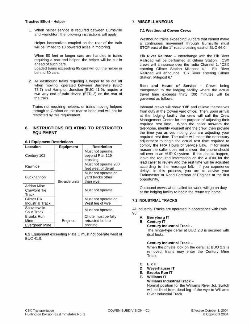
CSX Transportation COWEN SUBDIVISION - CJ Effective October 1, 2004 Huntington Division East Timetable No. 1 © Copyright 2004
Tractive Effort - Helper
1. When helper service is required between Burnsville and Frenchton, the following instructions will apply:
Helper locomotives coupled on the rear of the train will be limited to 18 powered axles in motoring. When 80 feet or longer cars are handled in trains requiring a rear-end helper, the helper will be cut in ahead of such cars. Loaded trains exceeding 95 cars will cut the helper in behind 80 cars.
2. All eastbound trains requiring a helper to be cut off
when moving, operated between Burnsville (BUC 73.7) and Hampton Junction (BUC 41.9), require a two way end-of-train device (ETD 2) on the rear of the train.
Trains not requiring helpers, or trains moving helpers through to Grafton on the rear or head-end will not be restricted by this requirement.
6. INSTRUCTIONS RELATING TO RESTRICTED
EQUIPMENT 6.1 Equipment Restrictions Location Equipment Restriction
Century 102 Must not operate beyond Rte. 119 crossing
Rawhide Must not operate 200 feet west of derail
Buckhannon Must not operate on yard tracks other than wye
Adrian Mine Crawford Tie Track
Must not operate
Gilmer Elk Industrial Track
Must not operate on West leg of wye
Shaversville Spur Track
Six-axle units
Must not operate
Brooks Run Mine Evergreen Mine
Engines Chute must be fully retracted before passing
6.2 Equipment exceeding Plate C must not operate west of BUC 41.9.
7. MISCELLANEOUS
7.1 Westbound Cowen Crews Westbound trains exceeding 90 cars that cannot make a continuous movement through Burnsville must STOP east of the 1st road crossing east of BUC 66.0. Elk River Railroad – Interchange with the Elk River Railroad will be performed at Gilmer Station. CSX crews will announce over the radio Channel 1, “CSX entering Gilmer Station Milepost 4.” Elk River Railroad will announce, “Elk River entering Gilmer Station, Milepost 6.” Rest and Hours of Service – Crews being transported to the lodging facility where the actual travel time exceeds thirty (30) minutes will be governed as follows: Inbound crews will show “Off” and relieve themselves from duty at the Cowen yard office. Then, upon arrival at the lodging facility the crew will call the Crew Management Center for the purpose of adjusting their required rest time. When the caller answers the telephone, identify yourself and the crew, then provide the time you arrived noting you are adjusting your required rest time. The caller will make the necessary adjustment to begin the actual rest time required to comply the FRA Hours of Service Law. If for some reason the caller does not answer, the phone should roll over to an AUDIX system. If this should happen, leave the required information on the AUDIX for the lead caller to review and the rest time will be adjusted according to the message left. If you experience delays in this process, you are to advise your Trainmaster or Road Foreman of Engines at the first opportunity. Outbound crews when called for work, will go on duty at the lodging facility to begin the return trip home.
7.2 INDUSTRIAL TRACKS All Industrial Tracks are operated in accordance with Rule 96.
A. Berryburg IT B. Century IT
Century Industrial Track - The hinge-type derail at BUO 2.3 is secured with dual locks. Century Industrial Track – When the private lock on the derail at BUO 2.3 is removed, trains may enter the Century Mine Track.
C. Elk IT D. Weyerhauser IT E. Brooks Run IT F. Williams IT
Williams Industrial Track – Normal position for the Williams River Jct. Switch will be lined from dead leg of the wye to Williams River Industrial Track.

CSX Transportation COWEN SUBDIVISION - CJ Effective October 1, 2004 Huntington Division East Timetable No. 1 © Copyright 2004
NOTES
NOTES
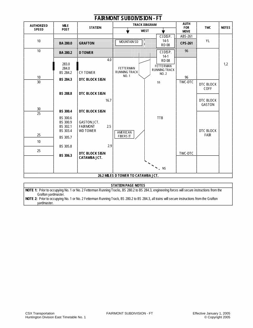
CSX Transportation FAIRMONT SUBDIVISION - FT Effective January 1, 2005 Huntington Division East Timetable No. 1 © Copyright 2005
FAIRMONT SUBDIVISION - FT TRACK DIAGRAM AUTHORIZED
SPEED MILE POST STATION
WEST
AUTH FOR
MOVE TWC NOTES
ABS-261 10
BA 280.0 GRAFTON
CPS-261
YL
10 96
BA 280.2 D TOWER
4.0 283.0 1,2 284.0 BS 284.2 CY TOWER
10 96 30
BS 284.3 DTC BLOCK SIGN ss TWC-DTC
DTC BLOCK COFF
BS 288.8 DTC BLOCK SIGN
16.7 DTC BLOCK GASTON
30 25
BS 300.4 DTC BLOCK SIGN
BS 300.6 TTB BS 300.9 GASTON JCT. BS 302.1 FAIRMONT 2.5 BS 303.4 WD TOWER DTC BLOCK
25 FAIR BS 305.7
10
BS 305.8 25
TWC-DTC
BS 306.3 DTC BLOCK SIGN CATAWBA JCT.
26.2 MILES D TOWER TO CATAWBA JCT.
STATION PAGE NOTES NOTE 1: Prior to occupying No. 1 or No. 2 Fetterman Running Tracks, BS 280.2 to BS 284.3, engineering forces will secure instructions from the
Grafton yardmaster. NOTE 2: Prior to occupying No. 1 or No. 2 Fetterman Running Track, BS 280.2 to BS 284.3, all trains will secure instructions from the Grafton
yardmaster.
MOUNTAIN SD
FETTERMAN RUNNING TRACK
NO. 1
FETTERMAN RUNNING TRACK
NO. 2
CI DISP. 14-5
RD 08
CI DISP. 14-1
RD 08
AMERICAN FIBERS IT
2.9
NS

CSX Transportation FAIRMONT SUBDIVISION - FT Effective January 1, 2005 Huntington Division East Timetable No. 1 © Copyright 2005
FAIRMONT SUBDIVISION SPECIAL INSTRUCTIONS
1. INSTRUCTIONS RELATING TO OPERATING RULES
Standard Clocks Station Location Grafton Crew Room Spring Switches
Designated Speed in Normal Position
Location Normal
Position for Movement
on
Facing Movement
When Springing
CY Tower Fetterman RT No. 2
10 MPH 10 MPH
Hand Brakes - Cars The following chart applies to locomotives, cars and trains left unattended. Between Location/Milepost Loads Empties BS 280.2 and BS 306.3 20% 10% Fetterman: all trains 5 HB 5 HB 2. INSTRUCTIONS RELATING TO SAFETY
RULES
NONE 3. INSTRUCTIONS RELATING TO COMPANY
POLICIES AND PROCEDURES
NONE 4. INSTRUCTIONS RELATING TO EQUIPMENT
HANDLING RULES Trains Equipped With Air Dump System: Coal or ballast trains departing Grafton enroute to Newell, PA will have the air dump system coupled and the main reservoir air cut in. Coal or ballast trains enroute from Newell, PA upon arrival at Grafton will have the air dump system disconnected. 5. INSTRUCTIONS RELATING TO AIR BRAKE
AND TRAIN HANDLING RULES
NONE 6. INSTRUCTIONS RELATING TO EQUIPMENT
RESTRICTIONS
NONE
7. MISCELLANEOUS 7.1 Industrial Tracks
A) American Fibers Industrial Track 1. Bridge 372 on the American Fibers IT is a Through-Truss Bridge.
NOTES

CSX Transportation G&E SUBDIVISION - GE Effective January 1, 2005 Huntington Division East Timetable No. 1 © Copyright 2005
G&E SUBDIVISION - GE TRACK DIAGRAM AUTHORIZED
SPEED MILE POST STATION
WEST
AUTH FOR
MOVE TWC NOTES
10 96
10 CAF 20.6 G&E JCT. 96
96 10 CAJ 0.0 G&E JCT.
1.7 96
CAJ 2.0 DTC BLOCK SIGN FOOTHILL
5.5 TWC-DTC
CAJ 7.5 BELLBURN 2.0 DTC BLOCK HOMINY CAJ 9.0 HOMINY CREEK
CAJ 9.1 DTC BLOCK SIGN DTC BLOCK CAJ 13.2 PEASER JCT. PEASER
10
CAJ 14.2 DTC BLOCK SIGN END OF MAIN TRACK TWC-DTC
14.2 MILES G&E JCT. TO END OF MAIN TRACK
SEWELL VALLEY SD BJ DISP. 14-7
RD 08
BJ DISP. 14-7
RD 08 HOMINY CREEK
IT
PEASER IT

CSX Transportation G&E SUBDIVISION - GE Effective January 1, 2005 Huntington Division East Timetable No. 1 © Copyright 2005
G&E SUBDIVISION SPECIAL INSTRUCTIONS
1. INSTRUCTIONS RELATING TO OPERATING RULES
Hand-Operated Switches G&E JCT The normal position of the switch at G&E Jct. is for movement to the G&E SD. Peaser Jct. The normal position of the switch at Peaser Jct. is for movement on the G&E SD towards the end of the track. 2. INSTRUCTIONS RELATING TO SAFETY
RULES
NONE 3. INSTRUCTIONS RELATING TO COMPANY
POLICIES AND PROCEDURES
NONE 4. INSTRUCTIONS RELATING TO EQUIPMENT
HANDLING RULES
NONE 5. INSTRUCTIONS RELATING TO AIR BRAKE
AND TRAIN HANDLING RULES
NONE 6. INSTRUCTIONS RELATING TO EQUIPMENT
RESTRICTIONS
NONE 7. MISCELLANEOUS 7.1 Industrial Tracks A) Hominy Creek IT
Hominy Creek IT from MP 0.0 Hominy Creek Jct. and MP 1.0, end of track, is designated excepted track.
B) Peaser IT
NOTES
NOTES

CSX Transportation GAULEY SUBDIVISION - GU Effective January 1, 2005 Huntington Division East Timetable No. 1 © Copyright 2005
GAULEY SUBDIVISION - GU TRACK DIAGRAM AUTHORIZED
SPEED MILE POST STATION
WEST
AUTH FOR
MOVE TWC NOTES
P F ABS-261 45 35 CA 415.0 GU CABIN
DTC BLOCK HAWK
1,2
CAY 0.0 GAULEY
1.5 96
10 CAY 1.5 DTC BLOCK SIGN
K&M JCT TWC-DTC DTC BLOCK GAULEY 5.4
CAY 6.9 DTC BLOCK SIGN RICH CREEK JCT DTC BLOCK
0.4 RICH
CAY 7.3 DTC BLOCK SIGN BELVA
DTC BLOCK BELVA
CAY 12.7 DTC BLOCK SIGN DTC BLOCK VAUGHN
10 TWC-DTC
CAY 17.5 DTC BLOCK SIGN 96 14.6 9,237 FT CAY 22.0 FOLA END OF MAIN TRACK 96
22.0 MILES GAULEY TO FOLA
STATION PAGE NOTES NOTE 1: Signal aspects displayed are in accordance with Signal Aspect Rules C1281 - C1298. NOTE 2: MP CA 415.0 trains in excess of 14,000 tons must not exceed 25 MPH.
NEW RIVER SD AM DISP 14-8
RD 08
NS RR
VAUGHN RR
BJ DISP. 14-7
RD 08
NS RR
CSX Transportation GAULEY SUBDIVISION - GU Effective January 1, 2005 Huntington Division East Timetable No. 1 © Copyright 2005
GAULEY SUBDIVISION SPECIAL INSTRUCTIONS 1. INSTRUCTIONS RELATING TO OPERATING
RULES The Vaughn RR between MP CAY 6.9 and MP CAY 22.0 is operated under CSX Operating Rules and is dispatched by the CSX BJ train dispatcher in Jacksonville, Florida. Tracks Other Than Main Tracks Trains and engines will not exceed 10 MPH on tracks other than main tracks.
Hand-Operated Switches K&M Jct. The normal position is for movement to the Gauley SD. Rich Creek Jct/NS Connection The normal position for this switch is as last used. Trains will approach this location prepared to STOP expecting it to be lined against their movement. 2. INSTRUCTIONS RELATING TO SAFETY
RULES NONE
3. INSTRUCTIONS RELATING TO COMPANY
POLICIES AND PROCEDURES
NONE 4. INSTRUCTIONS RELATING TO EQUIPMENT
HANDLING RULES
NONE 5. INSTRUCTIONS RELATING TO AIR BRAKE AND
TRAIN HANDLING RULES
NONE 6. INSTRUCTIONS RELATING TO EQUIPMENT
RESTRICTIONS NONE
7. MISCELLANEOUS INSTRUCTIONS
NONE
NOTES

CSX Transportation GEORGES CREEK SUBDIVISION - GK Effective January 1, 2005 Huntington Division East Timetable No. 1 © Copyright 2005
GEORGES CREEK SUBDIVISION - GK TRACK DIAGRAM AUTHORIZED
SPEED MILE POST STATION
WEST
AUTH FOR
MOVE TWC NOTES
10 TWC-DTC
BAH 26.5 WESTERNPORT
DTC BLOCK POLAND
31.5 193 YL 10
BAI 31.5 WESTERNPORT 1
.8 BAI 30.7 FRANKLIN
2.3 BAI 28.4 MORRISON
193 YL
BAI 27.0 DTC BLOCK SIGN TWC-DTC DTC BLOCK
1.6 CONSOL BAI 26.8 STATE ROUTE 36 2 .5 BAI 26.3 DAWSON BAI 23.5 3.8 ABTH 5559 3 BAI 22.5 JACKSON JCT 3 .5 BAI 22.0 KNAPPS MEADOW .6
BAI 21.4 LONACONING JCT. MINE
.8 BAI 20.6 MIDLAND .7 BAI 19.9 OCEAN .6 BAI 19.3 CARLOS .5
BAI 18.8 PHILLIPS PLANT
18.7 DTC BLOCK
BAI 18.7
.1 CONSOL NO. 10 END OF TRACK TWC-DTC CONSOL
10 12.8 MILES WESTERNPORT TO CONSOL NO. 10
STATION PAGE NOTES
NOTE 1: Main St. Westernport 5 MPH head-end only. NOTE 2: Do not exceed 8 MPH at State Rt. 36, BAI 26.8. NOTE 3: Do not exceed 8 MPH over crossings at Lonaconing BAI 22.5 to BAI 23.5.
THOMAS SD CI DISP. 14-5
RD 08
CI DISP. 14-5
RD 08

CSX Transportation GEORGES CREEK SUBDIVISION - GK Effective January 1, 2005 Huntington Division East Timetable No. 1 © Copyright 2005
GEORGES CREEK SUBDIVISION SPECIAL INSTRUCTIONS
1. INSTRUCTIONS RELATING TO OPERATING RULES
Excepted Track The entire Georges Creek SD is designated as excepted track. Highway Crossings at Grade 1. Entire Subdivision - Trains must approach highway
grade crossings equipped with automatic highway warning devices, prepared to comply with Rule 100-E.
2. Morrison Road Crossing – A CSX crew member, upon notification from Tri-Star of a vehicle needing to traverse the tracks, will be transported to the crossing by Tri-Star and will clear the crossing. A. Unless there are train operating restrictions, the
expected delay will be less than 15 minutes. B. In the event of a fire or emergency, the crossing
will be cleared as quickly as possible. Hand Brakes - Cars The following chart applies to trains standing on a heavy grade, locomotives attached and the crew stays with the train.
Between Location/Milepost Loads Empties BAI 18.7 and BAI 31.5 20% 10%
Hand-Operated Switches Westernport - Trains entering or leaving the Georges Creek Subdivision may leave the main track switch at Westernport lined as last used. Trains will approach this switch expecting to find it lined against their movement. 2. INSTRUCTIONS RELATING TO SAFETY
RULES Exceptions to Making A Safety Stop Employees will make the safety STOP as required by Safety Rule 2201 in all cases except at the locations described below: Doubling Up Loaded Trains at Phillips Mine and Consol: Crews doubling up loaded trains at the above listed locations must comply with safety rules and SOFA recommendations except for Safety Rule 2201 (safety STOP) and must comply with the following: 1) Safety Rule 2001- A job briefing must be conducted in
which the movement to be made is discussed. 2) Safety Rule 2201 - Employees must not ride to the
coupling. 3) Safety Rule 2101 - Employees must not mount or
dismount moving equipment.
4) Operating Rule 421 - When radios are used for communication, crews must give clear and accurate car lengths for the movement to be made.
3. INSTRUCTIONS RELATING TO COMPANY
POLICIES AND PROCEDURES NONE 4. INSTRUCTIONS RELATING TO EQUIPMENT
HANDLING RULES
NONE
5. INSTRUCTIONS RELATING TO AIR BRAKE AND TRAIN HANDLING RULES
NONE
6. INSTRUCTIONS RELATING TO EQUIPMENT
RESTRICTIONS
Location Equipment Restriction
Entire Subdivision Six-axle units, Cars 70 ft. or longer
Must not operate
Consol No. 10 Coal track
Must not Operate under tipple,
conveyor or ramp tracks 1&2
Mine No. 5
Engines
Must not Operate under tipple
7. MISCELLANEOUS
7.1 Mine No. 5 - The locomotives should be moved over the road crossing on the mine lead before shoving empties across the road crossing. 7.2 Mine No. 5 – Do not exceed 5 MPH for all movements on Mine No. 5 tracks.
NOTES
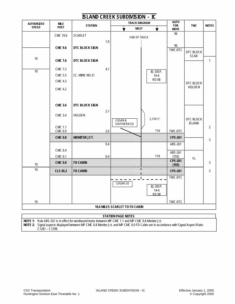
CSX Transportation ISLAND CREEK SUBDIVISION - IC Effective January 1, 2005 Huntington Division East Timetable No. 1 © Copyright 2005
ISLAND CREEK SUBDIVISION - IC TRACK DIAGRAM AUTHORIZED
SPEED MILE POST STATION
WEST
AUTH FOR
MOVE TWC NOTES
96 CMC 10.6 SCARLET END OF TRACK
1.0 96
CMC 9.6 DTC BLOCK SIGN TWC-DTC
10
DTC BLOCK SCAR
CMC 7.6 DTC BLOCK SIGN
1
CMC 7.2 4.1 10 CMC 5.5 I.C. MINE NO.21
CMC 4.3 DTC BLOCK HOLDEN
CMC 4.2
CMC 3.6 DTC BLOCK SIGN 2.1 CMC 3.4 HOLDEN 2,178 FT. DTC BLOCK ISLAND CMC 1.1 2 CMC 0.9 2.6 TTB TWC-DTC
CMC 0.8 MONITOR JCT.
CPS-261 3
0.4 ABS-261
CMC 0.4 ABS-261 CMC 0.1 0.4 TTB (193)
CPS-261 10 CMC 0.0 FD CABIN
(193)
YL 3
10 CLS 65.2 FD CABIN
CPS-261 3
TWC-DTC
10 TWC-DTC
10.6 MILES SCARLET TO FD CABIN
STATION PAGE NOTES
NOTE 1: Rule ABS-261 is in effect for westbound trains between MP CMC 1.1 and MP CMC 0.8 Monitor Jct. NOTE 2: Signal aspects displayed between MP CMC 0.8 Monitor Jct. and MP CMC 0.0 FD Cabin are in accordance with Signal Aspect Rules C1281 – C1298.
BJ DISP. 14-4
RD 08
LOGAN & SOUTHERN SD
LOGAN SD BJ DISP.
14-4 RD 08

CSX Transportation ISLAND CREEK SUBDIVISION - IC Effective January 1, 2005 Huntington Division East Timetable No. 1 © Copyright 2005
ISLAND CREEK SUBDIVISION SPECIAL INSTRUCTIONS 1. INSTRUCTIONS RELATING TO OPERATING
RULES Hand Brakes - Cars The following table lists exceptions to operating Rule 103-D. These exceptions are the minimum number of hand brakes to be applied at that location.
Location Loaded Empty Comments Scarlet 8 HB 8 HB Per Cut Of Empties Use Of Specified Tracks Massey Coal Company has leased the track between MP CMC 0.8 and CMC 9.6. The leased track is operated under CSX Operating Rules and dispatched by the CSX BJ train dispatcher in Jacksonville, FL. Between MP CMC 9.6 and MP CMC 10.6, trains will operate in accordance with Operating Rule 96. 2. INSTRUCTIONS RELATING TO SAFETY
RULES NONE
3. INSTRUCTIONS RELATING TO COMPANY
POLICIES AND PROCEDURES
NONE 4. INSTRUCTIONS RELATING TO AIR BRAKE
AND TRAIN HANDLING RULES
NONE 5. INSTRUCTIONS RELATING TO EQUIPMENT
HANDLING RULES
NONE 6. INSTRUCTIONS RELATING TO EQUIPMENT
RESTRICTIONS NONE
7. MISCELLANEOUS 7.1 The main track is out of service beginning at the west
end of the tunnel at MP CMC 7.2. Trains or engines will not operate beyond MP CMC 7.2.
7.2 No more than 90 cars can be handled at any time
between MP CMC 0.8 and MP CMC 7.2.
NOTES

CSX Transportation JAMES RIVER SUBDIVISION - JR Effective January 1, 2005 Huntington Division East Timetable No. 1 © Copyright 2005
JAMES RIVER SUBDIVISION - JR TRACK DIAGRAM AUTHORIZED
SPEED MILE POST STATION
WEST
AUTH FOR
MOVE TWC NOTES
ABS-261
DTC BLOCK P F GREEN
35 35 CAB 119.2 GLADSTONE CPS-261 CAB 119.2 GLADSTONE 1 35 35
CPS-261
ABS-251 DTC BLOCK 1=W 2=E LIVELY
CAB 123.0 6.9
1 2 DTC BLOCK ABS-251 WALKER
CAB 126.0 WALKERFORD
CPS-261
131.0 9.8 (1) HBD, DED, AC DTC BLOCK 132.0 ABS-261
JOSH
CAB 135.1 EAST JOSHUA FALLS
CPS-261
CSDG 7,100 FT.
ABS-261 DTC BLOCK
THREE
CAB 136.6 WEST JOSHUA FALLS
CPS-261
ABS-261
7.2
CAB 142.5 ABS-261
(193)
YL
CAB 143.1 TYREE
ABS-251 3.0 (193) 1=W 2=E
CAB 146.1 LYNCHBURG
CPS-261
1 2 ABS-251
35 35 (193) 25 25
CAB 146.3 1.2
25 25 35 35
CAB 146.9 ABS-251
(193) CAB 147.3 SOUTHERN CROSSING CPS-261 YL
CAB 147.4
2.6 ABS-261 (193) DTC BLOCK
CAB 149.5 EAST REUSENS
CPS-261
REUSEN
CSDG 5,250 FT. ABS-261 35 35
AL DISP. 14-3
RD 08
AL DISP. 14-2
RD 08
RIVANNA SD
NS RR

CSX Transportation JAMES RIVER SUBDIVISION - JR Effective January 1, 2005 Huntington Division East Timetable No. 1 © Copyright 2005
JAMES RIVER SUBDIVISION - JR TRACK DIAGRAM AUTHORIZED
SPEED MILE POST STATION
WEST
AUTH FOR
MOVE TWC NOTES
P F 35 35 CAB 150.6 WEST REUSENS CPS-261 DTC BLOCK CAB 150.8 (2) HBD-DED-AC-AD ABS-261 REUSEN
CAB 151.7 SDF CAB 152.8 SDF CAB 153.9 SDF CAB 154.1 SDF
35 35 30 30
CAB 154.8
CAB 155.0 SDF CAB 155.1 SDF CAB 155.4 SDF
30 30 35 35
CAB 155.6 SDF
CAB 156.3 SDF CAB 156.4 SDF CAB 156.8 SDF CAB 157.2 SDF 9.1 ABS-261 DTC BLOCK REUSEN
CAB 158.2 EAST PEARCH
CPS-261
DTC BLOCK PEARCH CAB 159.9 SDF CSDG 10,030 FT. CAB 160.5
SDF ABS-261
CAB 160.2 WEST PEARCH
CPS-261
ABS-261 CAB 161.4 SDF
35 35 30 30
CAB 161.8 CAB 162.2
SDF 4.8 CAB 163.0 (2) HBD-DED-AC-AD ABS-261 DTC BLOCK PEARCH
CAB 163.6 EAST WAUGH
CPS-261
DTC BLOCK WAUGH
30 30 CSDG 6,750 FT. 35 35
CAB 164.5 ABS-261
CAB165.0 WEST WAUGH
CPS-261
3.5 ABS-261 CAB 167.3 MAJOR CPS-261
35 35 6.4
ABS-261 DTC BLOCK WAUGH

CSX Transportation JAMES RIVER SUBDIVISION - JR Effective January 1, 2005 Huntington Division East Timetable No. 1 © Copyright 2005
JAMES RIVER SUBDIVISION - JR TRACK DIAGRAM AUTHORIZED
SPEED MILE POST STATION
WEST
AUTH FOR
MOVE TWC NOTES
P F 35 35
ABS-261 DTC BLOCK
WAUGH
CAB 173.7 SD CABIN
No. 1 No. 2 1.3
CPS- ABS- CAB 175.0 BALCONY FALLS
261 251
0.3 1 2 2=E
DTC BLOCK FALLS
CAB 175.3 K CABIN
2.9
CAB 178.2 NATURAL BRIDGE
CPS-261
7.0 CAB 179.9 (1) HBD-DED- AC-AD
ABS-261
DTC BLOCK BRIDGE
CAB 184.1 EAST ALPINE
CPS-261
CSDG 7,920 FT. ABS-261
CAB 185.6 WEST ALPINE
CPS-261
ABS-261
35 35 SDF 30 30
CAB 185.7 CAB 186.0
SDF
30 30 35 35
CAB 186.5
CAB 188.9 SDF 35 35 DTC BLOCK 30 30
CAB 189.4 ALPINE
30 30 25 25
CAB 189.9 CAB 190.2
SDF 25 25 10.0 35 35
CAB 191.3
CAB 192.6 SDF CAB 192.7
WASP ROCK TUNNEL CAB 193.2 SDF ABS-261 CPS-261
CAB 195.2 EAST BUCHANAN
ABS-251
CAB 198.8 5.0 1=W 2=E DTC BLOCK
CAB198.9 WAS SPRINGWOOD 1 2 BUCK ABS-251
CAB 200.2 JN CABIN CPS-261
CAB 200.3 2.1 SDF ABS-261 CAB 200.6 SDF CAB 200.9
(1) HBD-DED-AC
CAB 201.8 35 35
MED
IUM
SPE
ED
25 M
PH
CAB 201.9 LITTLE TUNNEL
ABS-261
DTC BLOCK LYLE
NS RR
GLASGOW IT

CSX Transportation JAMES RIVER SUBDIVISION - JR Effective January 1, 2005 Huntington Division East Timetable No. 1 © Copyright 2005
JAMES RIVER SUBDIVISION - JR TRACK DIAGRAM AUTHORIZED
SPEED MILE POST STATION
WEST
AUTH FOR
MOVE TWC NOTES
P F DTC BLOCK 35 35 LYLE 25 25
CAB 202.0
ABS-261
Med
. Sp.
25
MPH
CAB 202.2 ABS-261
25 25 35 35
CAB 202.3 LYLE
CPS-261
ABS-261 35 35 30 30
CAB 204.6 SDF
CAB 205.0
SDF
30 30 25 25
CAB 207.2 9.7
CAB 207.5 CAB 207.6
BELLS TUNNEL
25 25 35 35
CAB 207.8
35 35 30 30
CAB 210.4
30 30 35 35
CAB 210.7
ABS-261 DTC BLOCK LYLE
CAB 211.6 EAST EAGLE ROCK
CPS-261
CSDG 9,530 FT. ABS-261
CAB 213.5 WEST EAGLE ROCK
CPS-261
ABS-261 CAB 216.9 DTC BLOCK
35 35 EAGLE 30 30
CAB 217.9 SDF
CAB 218.1
SDF 6.6 ABS-261
CAB 218.3 EAST HADEN
CPS-261
ABS-261
30 30 DTC BLOCK 35 35
CAB 218.4 CSDG 7,720 FT. HADEN
35 35 ABS-261

CSX Transportation JAMES RIVER SUBDIVISION - JR Effective January 1, 2005 Huntington Division East Timetable No. 1 © Copyright 2005
JAMES RIVER SUBDIVISION - JR TRACK DIAGRAM AUTHORIZED
SPEED MILE POST STATION
WEST
AUTH FOR
MOVE TWC NOTES
P F 35 35
ABS-261
CAB 219.8 WEST HADEN
CPS-261
ABS-261 CAB 220.6 TTB CAB 221.8 (2) HBD-DED-AD-AD CAB 224.5 SDF DTC BLOCK 225.0 HADEN 225.1 SDF 226.0 9.0 CAB 227.5
CAB 227.6 IRON GATE
ABS-251 1=W 2=E
DTC BLOCK GATE
CAB 228.7 ABS-251 YL
(193) 35 35 25 25
CAB 229.3
TTB 1.8 1 2 ABS-251
25 25 CAB 229.4 JD CABIN
(193) YL 1 ABS-261 YL
P F
UN
DER
10,
000
TON
S O
VER
10,
000
TON
S
CAB 229.4 JD CABIN
35 40 25
ABS-261 YL
110.2 MILES GLADSTONE TO JD CABIN
STATION PAGE NOTES NOTE 1: All signals are Signal Rules C1281 – C1298. Except at Gladstone Rivanna SD CAB 119.2 all signals are Signal Rules 1281-1298.
AM DISP. 14-4
RD 08
ALLEGHANY SD

CSX Transportation JAMES RIVER SUBDIVISION - JR Effective January 1, 2005 Huntington Division East Timetable No. 1 © Copyright 2005
JAMES RIVER SUBDIVISION SPECIAL INSTRUCTIONS
1. INSTRUCTIONS RELATING TO OPERATING RULES
Yard Limits Lynchburg Yard
Main Track – Lynchburg yard engines may work in both directions between Southern Crossing and Tyree, on either or both tracks within the time limits as authorized by the train dispatcher, without flag protection. The train dispatcher will not authorize the requested time limits unless the absolute block signals governing movement onto the track sections to be occupied by the yard engine have been blocked to display a STOP indication and record made of the time limits. Blocking will not be removed, nor a train or engine authorized to enter the track section authorized, until the conductor has reported the track section clear to the Jacksonville dispatcher. The conductor will see that the yard engine is clear of the main track at least five (5) minutes before the expiration of the time limits and will report clear to the Jacksonville dispatcher. When the yard engine has reported clear prior to the expiration of the time limits that track section must not again be occupied unless a new time limit authority is obtained. Use Of Specified Tracks Lynchburg
a) Lynchburg – Instructions of the NS yardmaster must be secured before fouling NS lead to CSXT freight house track.
b) NS interchange tracks – NS interchange tracks are numbered from main track No. 1 through No. 5. Crews setting off must use Nos. 3 and 4 tracks. Waybills must be left in bill box.
Track capacity – Track capacities are as follows: No. 1 – 38 car lengths No. 2 – 35 car lengths No. 3 – 27 car lengths No. 4 – 25 car lengths
c) Archer Creek - Industrial tracks, Numbers 1 and 2,
and the Industrial lead serving Lynchburg Foundry are to be used jointly by CSXT trains and Lynchburg Foundry engine.
d) Lynchburg Yard - At the beginning of the tour of
duty, cars on tracks L01 through L06 will be physically checked to ensure that there are sufficient hand brakes applied on the east-end of the track. Cars on these tracks will be shoved far enough eastbound to accommodate cars that will be switched into those tracks. If there is any doubt that cars are moved past the clearance point while switching, the track must be physically checked for clearance.
Crews will take into consideration the following when switching: • How much track space is available before
switching, dropping or kicking cars. • Load/Empty ratio of cars in tracks. • Are hand brakes applied on loaded or empty
cars? Remember that hand brakes applied on empty cars will frequently slide the wheels when the cars are moved. A sliding wheel offers very little retarding force.
• Cars will not be moved if the wheels are sliding. Sliding wheels contribute to wheel defects and failures. If a wheel is seen to be sliding, STOP the movement and correct the problem, then proceed.
• What is the tonnage of cars being dropped or kicked? Are sufficient hand brakes applied to control the movement?
• CAUTION: Loaded tank cars will move because of material sloshing inside the tank.
• If there is any doubt if cars will be shoved out of the clear to foul other tracks, don’t take a chance.
• Lynchburg Yard – The normal position of No. 7 track switch at the East End of Lynchburg yard is for straight track movement on the old westbound main yard track. No. 7 track at the east end of the lead is designated as a set off and pick up track. Crews must expect cars to be on this track at all times. Before switching cars into all other yard tracks, switches will be checked and precautions must be taken to ensure that cars will not roll out of the east end of the yard tracks into the lead.
e) Instructions must be obtained from the Lynchburg yardmaster before occupying yard tracks in Lynchburg. f) Ns Train Dispatcher NS Train Dispatcher radio channel is 22, tone 552. NS Train Dispatcher telephone number is 540-981-
3902. NS Crossing And Tyree Rule 251 is modified to allow trains or engines to cross over or enter main tracks between NS Crossing and Tyree upon hand signal from the employee handling the switches, who must secure permission for the intended move from the Jacksonville dispatcher. On-Track Equipment Instructions Between Southern crossing and Tyree – In addition to obtaining authority from the train dispatcher, oral instructions must be obtained from the Lynchburg yardmaster for OTE movements.

CSX Transportation JAMES RIVER SUBDIVISION - JR Effective January 1, 2005 Huntington East Division Timetable No. 1 © Copyright 2005
2. INSTRUCTIONS RELATING TO SAFETY RULES Exceptions to Making A Safety Stop Employees will make the safety STOP as required by Safety Rule 2201 in all cases except at the locations described below: 1) CAB 124.7 - While working Virginia Fiber Facility. 2) CAB 146.1 - While working Griffin Pipe over
radioactive scanner and tipple.
Crews working at the above listed locations must comply with safety rules and SOFA recommendations except for Safety Rule 2201 (safety STOP) and must comply with the following: 1) Safety Rule 2001 - A job briefing must be
conducted in which the movement to be made is discussed.
2) Safety Rule 2201 - Employees must not ride to the coupling.
3) Safety Rule 2101 - Employees must not mount or
dismount moving equipment. 4) Operating Rule 421 - When radios are used for
communication, crews must give clear and accurate car lengths for the movement to be made.
3. INSTRUCTIONS RELATING TO COMPANY
POLICIES AND PROCEDURES NONE 4. INSTRUCTIONS RELATING EQUIPMENT
HANDLING RULES Movement of Clearance Implicated Shipments Lynchburg 1. All tracks are prohibited except L07 and L10. L07 and
L10 can only be used if adjacent tracks have been physically checked and are clear of all cars.
2. Cars will be staged in the Shop Track. 3. Instructions/Clearance Wires are received and
reviewed by the yardmaster for movement in the yard. 4. I-04 will be used for interchange. I-03 must be
physically checked and clear of all cars. 5. The yardmaster protects movements in the yard. 5. INSTRUCTIONS RELATING TO AIR BRAKE
AND TRAIN HANDLING RULES NONE
6. INSTRUCTIONS RELATING TO EQUIPMENT RESTRICTIONS
Placement Of Empty Cars In Trains A. Empty cars 80 feet or longer must be placed in
trains so that the trailing tonnage does not exceed 7,800 tons westbound and 6,300 tons eastbound between JD Cabin MP CAB 229.4 and Lynchburg MP CAB 146.1
B. Between Lynchburg MP CAB 146.1 and
Gladstone MP CAB 119.2 when handling empty cars, 80 feet or longer, comply with Equipment Handling Rule 4466B.
Locomotive Restrictions Bucher Rail Service – CAB 150.3 – Six-axle locomotives must not operate. 7. MISCELLANEOUS 7.1 Glasgow Industrial Track Glasgow (Balcony Falls) – Drawbridge across track serving Burlington Industries is raised and lowered with a control switch located on the outside wall of main building south of track and west of bridge.
NOTES
CSX Transportation JAMES RIVER SUBDIVISION - JR Effective January 1, 2005 Huntington East Division Timetable No. 1 © Copyright 2005
NOTES
NOTES

CSX Transportation JARROLDS VALLEY SUBDIVISION - JV Effective January 1, 2005 Huntington Division East Timetable No. 1 © Copyright 2005
JARROLDS VALLEY SUBDIVISION - JV TRACK DIAGRAM AUTHORIZED
SPEED MILE POST STATION
WEST
AUTH FOR
MOVE TWC NOTES
END OF MAIN TRACK 10 CLP 15.3 RO JCT TWC-DTC
DTC BLOCK EAGLE
CLP 9.0 DTC BLOCK SIGN 7.3 CLP 8.0 AMEAGLE 1.2
10 DTC BLOCK 20
CLP 6.8 COLCORD JARR 2.2 CLP 4.6 TRUAX 4.6
20 CLP 0.0 JARROLDS VALLEY JCT TWC-DTC
96
CLL 35.6 JARROLDS VALLEY JCT
1,2
96
15.3 MILES PICARD TO JARROLDS VALLEY JCT.
STATION PAGE NOTES
NOTE 1: All trains entering or operating between MP CLL 31.0 and MP CLL 35.6 will operate according to Rule 96 and must receive instructions from the Elk Run yardmaster (when on duty) before lining switches or fouling tracks. The Elk Run yardmaster (when on duty) will issue instructions to crews operating between these mileposts.
NOTE 2: Prior to occupying tracks between MP CLL 31.0 and MP CLL 35.6, engineering forces will make arrangements with the Elk Run Yardmaster (when on duty) who is responsible for directing movements on these tracks.
BIG MARSH FORK SD
BIG COAL SD BJ DISP.
14-2 RD 08
ROWLAND IT
BJ DISP. 14-2
RD 08

CSX Transportation JARROLDS VALLEY SUBDIVISION - JV Effective January 1, 2005 Huntington Division East Timetable No. 1 © Copyright 2005
JARROLDS VALLEY SUBDIVISION SPECIAL INSTRUCTIONS 1. INSTRUCTIONS RELATING TO OPERATING
RULES Excepted Tracks The Jarrolds Valley SD is designated as excepted track between MP CLP 6.8 and MP CLP 15.3. Hand-Operated Switches The normal position of the Jarrolds Valley Jct. switch is lined for movement on the Big Marsh Fork SD. 2. INSTRUCTIONS RELATING TO SAFETY
RULES NONE 3. INSTRUCTIONS RELATING TO COMPANY
POLICIES AND PROCEDURES
NONE 4. INSTRUCTIONS RELATING TO EQUIPMENT
HANDLING RULES
NONE 5. INSTRUCTIONS RELATING TO AIR BRAKE
AND TRAIN HANDLING RULES
NONE 6. INSTRUCTIONS RELATING TO EQUIPMENT
RESTRICTIONS
NONE 7. MISCELLANEOUS
Rowland Industrial Track - Designated as excepted track.
NOTES
NOTES

CSX Transportation KANAWHA SUBDIVISION - KW Effective January 1, 2005 Huntington Division East Timetable No. 1 © Copyright 2005
KANAWHA SUBDIVISION - KW TRACK DIAGRAM AUTHORIZED
SPEED MILE POST STATION
WEST
AUTH FOR
MOVE TWC NOTES
P F CA 426.9
ABS-261
DTC BLOCK EAGLE
CA 427.9 MONTGOMERY 1 2 DTC BLOCK
1 30 30
CPS-261
PRATT 30 30 1 2 DTC BLOCK CA 428.2
PRATT 1
65 50 1.9
ABS-261
60 CA 429.3
CA 429.8 HANDLEY
CPS-261
2,3
60 CSDG 9,165 FT. 55
CA 431.2 ABS-261
2.1
CA 431.5
CA 431.9 W.E. PULLOUT TRACK
CPS-261
55 70
CA 432.1 0.3
ABS-261 DTC BLOCK
PRATT
CA 432.2 PAINT CREEK JCT
CPS-261 DTC BLOCK
433.0 1.5 ABS-261 PAINT 433.7 CROWN HILL CPS-261 434.0 4.3
70 CA 435.0
65 50 ABS-261 CA 435.2
35 35
79 50 CA 436.2
CA 438.0 E.E. CABIN CREEK
CPS-261
79 65
CA 438.2 0.3
ABS-261
CA 438.3 W.E. CABIN CREEK
CPS-261
4
65 70
CA 438.5 0.9
ABS-261 DTC BLOCK
PAINT
CA 439.2 CHELYAN
CPS-261
70
CA 440.5 65
CA 441.1
ABS-261 60
CA 441.3 2.3 DTC BLOCK
CA 441.5 CHESAPEAKE CPS-261 MARMET 70
CA 443.7
444.0 ABS-261 60
65 444.3
1 2 444.5 MARMET CPS-261 445.0
65 50 CA 445.5 (1) HBD-DEDAC ABS-261 1,2,3
CABIN CREEK
SD
AN DISP. 20-3
RD 08
NEW RIVER SD AM DISP.
14-8 RD 08
WINIFREDE IT

CSX Transportation KANAWHA SUBDIVISION - KW Effective January 1, 2005 Huntington Division East Timetable No. 1 © Copyright 2005
KANAWHA SUBDIVISION - KW TRACK DIAGRAM AUTHORIZED
SPEED MILE POST STATION
WEST
AUTH FOR
MOVE TWC NOTES
P F 65 50 1,2 79
CA 445.8 1 2 ABS-261
3
CA 448.3 2.9
CA 450.2 OWENS
CPS-261
4,5
CA 450.4 E.E. SOUTH RUFFNER
79
CA 450.6 65
SSDG
7,055 FT ABS-261
79 CA 450.8
DTC BLOCK 4,5
CA 451.8 W.E. SOUTH RUFFNER RUFFNER CPS-261
CA 453.2 E.E. CHARLESTON 79
CA 453.4
1TK 70 79
CA 454.0 ABS-261
2TK 60
70 CA 454.1
1.0
CA 454.2 W.E. CHARLESTON
CPS-261
CA 455.6 ELK 70 ABS-261 65
CA 456.1
SOUTH CHARLESTON CPS-261 DTC BLOCK
CA 457.0 ELK
CA 457.5 65
CA 458.0
ABS-261 55
65 CA 458.1
1.7
CA 458.7 SPRING HILL
CPS-261
460.0 2.3 ABS-261 460.5 DTC BLOCK 461.0 MP 461 CPS-261 ALBANS
65 79
CA 462.2 2.3
CA 462.9 ABS-261
CA 463.3 E.E. ST. ALBANS
CPS-261
79 50
CA 463.4 0.6 E CSDG
ABS-261 DTC BLOCK
6,656 FT. DOCK
CA 463.9 E.E. WESTWARD SDG
CPS-261 4
50 50 W SSDG 9,673 FT.
ABS-261 (193) 1,2,3
AN DISP. 20-3
RD 08

CSX Transportation KANAWHA SUBDIVISION - KW Effective January 1, 2005 Huntington Division East Timetable No. 1 © Copyright 2005
KANAWHA SUBDIVISION - KW TRACK DIAGRAM AUTHORIZED
SPEED MILE POST STATION
WEST
AUTH FOR
MOVE TWC NOTES
P F 50 50 W SDG ABS-261
1,2,3
0.9
CA 464.8 ST ALBANS
CPS-261
0.4 ABS-261 DTC BLOCK DOCK
CA 465.2 COAL DOCK
CPS-261
50 CPS ABS CA 465.8 W.E. WESTWARD SIDING 261 261 4
79 0.8 1 2 NO.1 NO.2
CA 466.0 E.E. DOCK SDG
CPS-261 DTC BLOCK
79 TTB SCOTT
CA 466.1 60
CSDG
8,369 FT. ABS-261 70
CA 466.3 1.9
CA 467.9 W.E. DOCK SDG
CPS-261
CA 468.0
70 ABS-261
60 CA 469.3
1.8
CA 469.7 SCARY
CPS-261
CA 470.2 3.5 (1) HBD-DEDAC ABS-261 DTC BLOCK SCOTT
CA 473.2 SCOTT
CPS-261
60
CA 473.9 70
DTC BLOCK 65
CA 476.7
ABS-261 HURRY
478.0 479.0 6.0
CA 479.2 HURRICANE
CPS-261
65
CA 480.3 DTC BLOCK 70
ABS-261
MILTON 79
CA 483.1 6.3
CA 486.5 MILTON
CPS-261
79 ABS-261
CA 486.6 60
79
CA 488.5
CA 489.6 (2) HBD-DEDAC DTC BLOCK 79 1 2 BARBER
CA 492.2
65 CA 494.0
55 50 ABS-261 1,2,3
COAL RIVER
SD
AN DISP. 20-3
RD 08
THOROUGHFARE
BILLS CREEK
IT
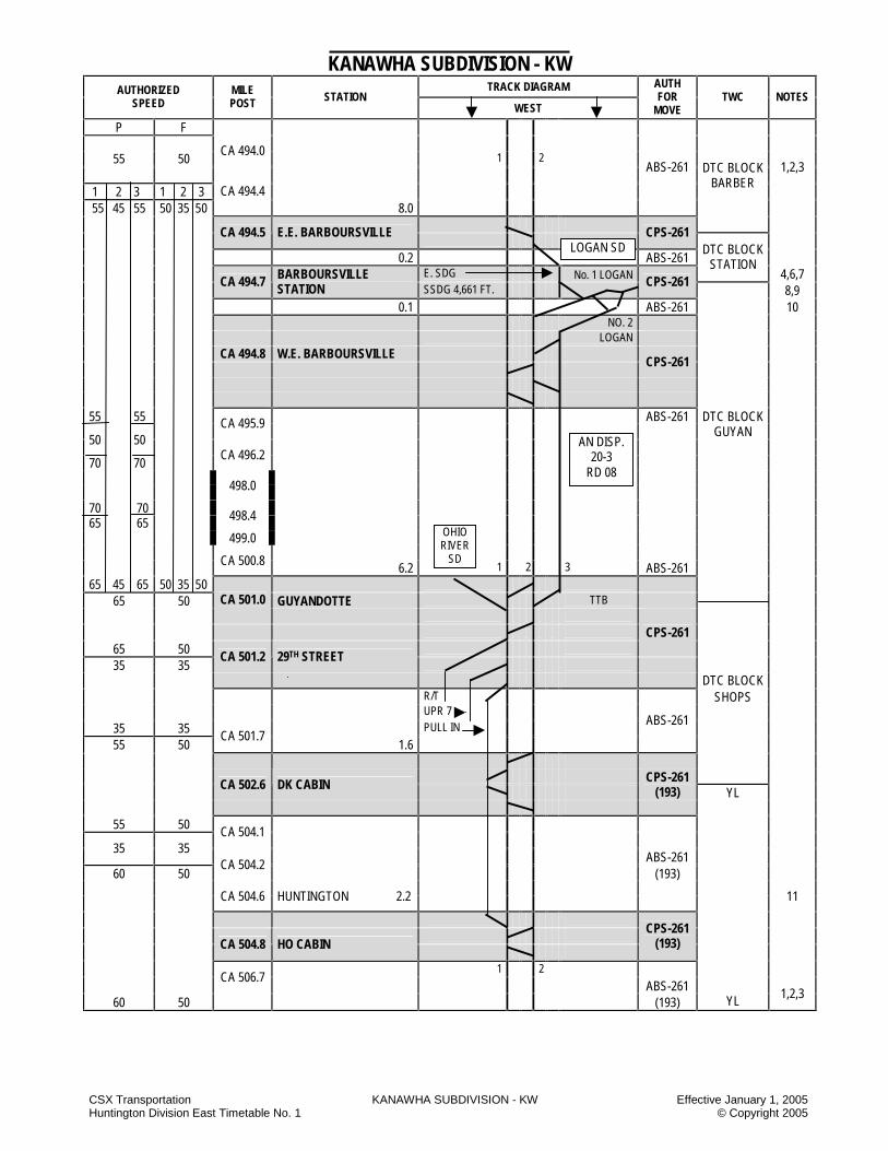
CSX Transportation KANAWHA SUBDIVISION - KW Effective January 1, 2005 Huntington Division East Timetable No. 1 © Copyright 2005
KANAWHA SUBDIVISION - KW TRACK DIAGRAM AUTHORIZED
SPEED MILE POST STATION
WEST
AUTH FOR
MOVE TWC NOTES
P F
CA 494.0
1 2 55 50
ABS-261 1,2,3
1 2 3 1 2 3
DTC BLOCK BARBER
55 45 55 50 35 50
CA 494.4 8.0
CA 494.5 E.E. BARBOURSVILLE
CPS-261
0.2 ABS-261 E. SDG No. 1 LOGAN
DTC BLOCK STATION
4,6,7
CA 494.7 BARBOURSVILLE STATION SSDG 4,661 FT.
CPS-261 8,9
0.1 ABS-261 10 NO. 2 LOGAN
CA 494.8 W.E. BARBOURSVILLE CPS-261
55 55 ABS-261 DTC BLOCK
CA 495.9
GUYAN 50 50
70 70
CA 496.2
498.0
70 70 65 65 498.4 499.0 CA 500.8 6.2 1 2 3 ABS-261 65 45 65 50 35 50
65 50 GUYANDOTTE TTB
CA 501.0
65 50
CPS-261
35 35 CA 501.2 29TH STREET
DTC BLOCK R/T SHOPS UPR 7
35 35 PULL IN ABS-261
55 50 CA 501.7
1.6
CA 502.6 DK CABIN CPS-261
(193) YL
55 50 CA 504.1 35 35
ABS-261 60 50
CA 504.2 (193)
CA 504.6 HUNTINGTON 2.2 11
CA 504.8 HO CABIN
CPS-261 (193)
1 2
CA 506.7 ABS-261
60 50 (193) YL 1,2,3
AN DISP. 20-3
RD 08
OHIO RIVER
SD
LOGAN SD
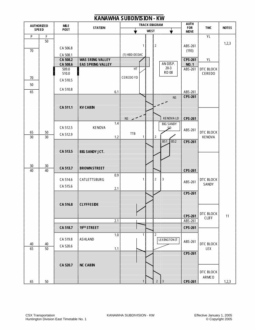
CSX Transportation KANAWHA SUBDIVISION - KW Effective January 1, 2005 Huntington Division East Timetable No. 1 © Copyright 2005
KANAWHA SUBDIVISION - KW TRACK DIAGRAM AUTHORIZED
SPEED MILE POST STATION
WEST
AUTH FOR
MOVE TWC NOTES
P F YL 50
1 2 ABS-261 1,2,3
70 CA 506.8
(193) CA 508.1 (1) HBD-DEDAC CA 508.2 WAS SRING VALLEY CPS-261 YL CA 508.6 EAS SPRING VALLEY NO. 1 HT ABS-261 DTC BLOCK
509.0 510.0 CEREDO
70 CEREDO YD
CA 510.5 50
65
CA 510.8 6.1 ABS-261
CPS-261
CA 511.1 KV CABIN
KENOVA LD CPS-261 1.4 CA 512.5 KENOVA
65 50 ABS-261 DTC BLOCK
30 30 CA 512.9
1.2 1 2 KENOVA BS1 BS2 CPS-261 BIG SANDY JCT.
CA 513.5
30 30 40 40
CA 513.7 BROWN STREET CPS-261 0.9 CA 514.6 CATLETTSBURG 1 2 3 DTC BLOCK ABS-261
SANDY
CA 515.6 2.1
CPS-261
CA 516.8 CLYFFESIDE
CPS-261 11 2.1 ABS-261
DTC BLOCK CLIFF
CA 518.7 19TH STREET
CPS-261
1.0 1 2 CA 519.8 ASHLAND
40 40 ABS-261 DTC BLOCK
65 50 CA 520.6
1.1 LEX CPS-261 DTC BLOCK
CA 520.7 NC CABIN
ARMCO 65 50 1 2 3 CPS-261 1,2,3
NS
NS
BIG SANDY SD
AN DISP. 20-3
RD 08
LEXINGTON IT
TTB

CSX Transportation KANAWHA SUBDIVISION - KW Effective January 1, 2005 Huntington Division East Timetable No. 1 © Copyright 2005
KANAWHA SUBDIVISION - KW TRACK DIAGRAM AUTHORIZED
SPEED MILE POST STATION
WEST
AUTH FOR
MOVE TWC NOTES
P F ABS-261
65 50
2.9 DTC BLOCK
1,2,3
ARMCO
CA 523.2 AK STEEL 0.3 1 2 3 ABS-261
65 50 CA 523.8 RUSSELL
CPS-261 DTC BLOCK 30 30
0.7 ABS-261 RUSSELL CPS-261 30 30 CA 524.2 RUSSELL YARD (193)
DTC BLOCK RUSSEL
30 30
ABS-261 (193)
94.7 MILES HANDLEY TO RUSSELL YARD
STATION PAGE NOTES
NOTE 1 Signals displayed are in accordance with Signal Aspect Rules C1281-C1298. NOTE 2 Trains in excess of 7,000 tons, but not exceeding 14,000 tons, must not exceed the speeds shown below:
BETWEEN MILEPOSTS MUST NOT EXCEED
MP CA 429.8 and MP CA 524.0 40 MP CA 494.7 and MP CA 501.0
on No. 2 Track 35
NOTE 3: Trains in excess of 14,000 tons must not exceed 35 MPH between MP CA 429.8 and MP CA 524.0. NOTE 4: Rules ABS-261 are in effect as designated below:
A) Cabin Creek JCT – wye tracks between apex of wye and No. 2 main track. B) Barboursville – east leg of wye to the eastward siding Barboursville and No. 1 Logan and No. 2 Logan tracks on west leg of wye. C) South Ruffner Siding off No. 2 track. D) St. Albans Westward Siding off No. 1 track. E) Barboursville off No. 2 track.
NOTE 5: Trains or engines operating on South Ruffner siding will not exceed 10 MPH. NOTE 6: Trains or engines will not exceed 10 MPH when using crossover No. 2 Kanawha SD to No. 1 or No. 2 track, Logan SD at Barboursville. NOTE 7: Trains or engines will not exceed 10 MPH when using turnout to No. 2 track, Kanawha SD to Logan SD. NOTE 8: Between CLS 0.0 and CLS 3.6 the authorized speed is 30 MPH. NOTE 9: Engine speed indicators, odometers and HTD equipment will be checked between MP CLS 0.0 and MP CLS 1.0. NOTE 10: For suspension of signal system, the BRICK DTC block extends between CLS 0.0 and CLS 3.6. NOTE 11: Between MP CA 504.8 and MP CA 516.8, trains or engines operating in accordance with a signal indication requiring medium speed will not
exceed 25 MPH.
AN DISP. 20-3
RD 08
RUSSELL TERMINAL SD

CSX Transportation KANAWHA SUBDIVISION - KW Effective January 1, 2005 Huntington Division East Timetable No. 1 © Copyright 2005
KANAWHA SUBDIVISION SPECIAL INSTRUCTIONS 1. INSTRUCTIONS RELATING TO OPERATING RULES Engine Bell Barboursville - Engine bells will be rung continuously while engines are using the east leg of the wye at Barboursville as a warning to reclamation plant employees. Engine Horn Huntington – All trains and engines will sound mild whistle signal 14(l) to warn employees in the vicinity at the following locations: 1) Trains on No. 1 and No. 2 tracks approaching the
16th Street yard office; 2) Westbound trains on No. 1 main track 500 feet west
of 16th Street yard office when pull-in track is occupied with equipment.
Highway Crossings at Grade South Ruffner Siding MP CA 450.7 – Trains setting off must cut cars off east/west of the two white posts, 150 feet from crossing. South Charleston – Westbound freight trains receiving a STOP aspect on WAS at MP CA 456.8 will STOP 2,200 feet east of signal crossing. St Albans: 1) Fifth Street – All trains must protect Fifth Street road
crossing at MP CA 465.5 when operating on thoroughfare track in accordance with Rule 100-J due to rusty rail.
2) Crossing protection timeout and restart circuits installed - Crossing protection timeout and restart circuits for “B”, ”C” and 2nd Streets in St. Albans have been installed on both No. 1 and No. 2 tracks between the EAS E.E. dock MP CA 466.1 and “B” Street, MP CA 465.9. Signs reading “crossing restart” have been installed 250 feet west of “B” Street. EastBOUND trains stopping between the EAS E.E. Dock and the “crossing restart” signs will initiate timeout circuits allowing the crossing protection at “B”, “C” and 2nd Streets to deactivate after three (3) minutes. The crossing protection will reactivate after the stopped trains have pulled by the “crossing restart” signs. Trains must be governed by Rule 100-E.
3) Trains using the upper yard tracks at St. Albans must approach Spruce Street and Walnut Street prepared to provide crossing protection in accordance with Rule 100-E due to rusty rail conditions.
Kerr Glass Crossing: Westbound trains receiving an approach signal at MP CA 500.1 and having a train length exceeding 7,200 feet must stop east of Kerr Glass crossing until a more favorable signal aspect is received. Huntington – Adams Avenue: All trains using the Huntington Belt Line at Adams Avenue grade crossing must approach this highway grade crossing prepared to provide crossing protection in accordance with Operating Rule 100-E due to rusty rail conditions. Switching South Charleston: BIDS has leased the west end of pit tracks P01 and P02. A yellow line indicates where the leased track begins. A derail will be in place at this yellow line during the time that BIDS facility personnel are working. CSX employees may occupy these tracks east of the yellow line at any time as directed by the yardmaster. When the derail is removed, it is permissible to enter the lease track to switch the BIDS facility as directed by the yardmaster. No engines or cars will be left west of the yellow line at any time except those spotted for the BIDS facility. Hand Brakes - Cars
Location Loaded Empty Comments Between MP CA 427.9 and MP CA 467.9 Between MP CA 489.0 and MP CA 524.0
5 HB 3 HB Trains in
excess of 60 cars
Huntington Yard 3 HB 2 HB ------ Hand-Operated Switches 1. Normal Position of Hand Operated Switches:
A) KV CABIN – Junction of KRT track and yard track – for movement to KRT track (Belt Line).
B) 20th Street Yard - Highside Switch – for movement on the Ohio River Company lead. This switch must remain locked when not in use.
C) Huntington Terminal – East leg of the wye Hill Track switch for movement on the east leg of the way
D) Huntington Terminal – East leg of the wye Coach Yard Lead switch, for movement on the east leg of the way.
Use Of Specified Tracks St Albans- Thoroughfare Track and No. 1 Yard Track: Restricting aspect, displayed for movement on the Thoroughfare track and No. 1 yard track, governs movement over the power-operated switches only. The train dispatcher will not route road trains via these tracks without instructions from the yardmaster. To avoid delay, the yardmaster will not permit such movements until all conflicting movements are under the yardmaster’s instructions. This instruction does not apply

CSX Transportation KANAWHA SUBDIVISION - KW Effective January 1, 2005 Huntington Division East Timetable No. 1 © Copyright 2005
to trains moving between the Kanawha SD and Coal River SD where Rules 261 are in effect. Scary – John Amos Power Plant: Tracks of John Amos Power Plant are used jointly by CSXT and John Amos engines. Huntington: 1) Westward Pull-In Track:
Eastbound movements on the westbound pull-in track must not be made without instructions from the yardmaster and train dispatcher, both of whom must afford full protection before allowing the movement.
2) 3rd Street Belt Line – Second Ave. and HO Cabin: Before moving over this track section instructions must be secured from the Huntington (HYCO) yardmaster.
3) 23rd Street Belt Line – Second Ave. and Shop Crossover: Before moving over this track section, instructions must be secured from the Huntington (HYCO) yardmaster.
Kenova: Trains with work to perform at Kenova will secure instructions from the Huntington (HYCO) yardmaster. Ashland - Clyffeside South Industrial Track: Movements on this track must not be made without instructions from the Coal Hump yardmsater. The following tracks are leased to A-K Steel: A) The Ashland Yard industrial lead between CA 522.8
and CA 519.3. B) 5th Street Yard: 1-2-3 and 4 north side. C) Bellefonte Yard north lead, south lead and runaround
tracks. D) Between MP CA 517.1 and MP CA 518.3 Tracks
A18 through A21; A22 and A23 east and west. CSXT crews will not occupy these tracks without instructions from the Coal Hump yardmaster, who will not issue instructions without permission from the A-K Steel Inc. Yardmaster. Interchange will be effected on all tracks except the Ashland industrial lead, No. 1 north side and the Bellefonte runaround, which will remain clear as running tracks. Rule 96 will govern movements on the tracks. All A-K Steel tracks at Ashland, KY, are now protected by red flags which indicate “STOP”. CSX crews should be prepared to STOP when a red flag is encountered. A-K Steel personnel will be responsible for the removal and replacement of red flags. If CSX crews encounter red flags that need to be removed, they should contact the Coal Hump yardmaster, Russell, KY, who will contact the proper authority at A-K Steel.
The following tracks are leased to Mansbach Metal Company: A) The Ashland industrial lead which locates adjacent
(north) to No. 1 main line between MP CA 517.1 (east end of 34th street) and MP CA 519.2 (directly under the 13th Street overhead bridge).
B) Tracks A01 through and including A08. C) Tracks A11 through and including A17. CSXT crews will not occupy these tracks without instructions from the Coal Hump yardmaster who will not issue instructions without acquiring permission of the Mansbach Metal Co. Interchange will be effected on all the above prescribed tracks. Rule 96 will govern movement on these tracks. CSXT will retain the use of tracks A09, A10 and the scale track. The use of these tracks will continue to be with instructions from the Coal Hump yardmaster. Leasing of Tracks at Ceredo, WV. The following Oglebay Norton tracks have been purchased by Electric Fuel Inc.: A) Ceredo yard tracks 1,2,3 and 4. B) Between the east end of 1, MP CA 508.3 and the
west end of Ceredo yard, MP CA 511.0. C) The loop from the west end of Ceredo yard to River
Terminal. D) 600 feet on the east end of old the B&O spur. CSXT crews will not occupy these tracks without instructions from the Huntington yardmaster, who will not issue instructions without acquiring permission of Kanawha River Terminals, Inc. CSXT crews must advise the Huntington yardmaster once work is complete and they have cleared the leased tracks. Tracks must not be reentered unless additional instructions are received from the Huntington yardmaster. Interchange will be effected on all the above prescribed tracks. Rule 96 will govern movement on these tracks. Leased Track to Ohio River Company: The following Huntington yard tracks have been leased by the Ohio River Company: A) 20th Street yard tracks. B) Smiley 1 through Smiley 8. C) All leads and connected trackage.
The lease point will start 400 feet east of the 20th Street road crossing on the East End Belt Line and 1,080 feet west of the 15th Street road crossing on the west end. This lease does not include Allied Warehouse, starting 370 feet east of the 25th Street road crossing. Entrance to this track (Allied Warehouse) will be governed by the Huntington (HYCO) yardmaster. Lease track limits will be designated by signs.
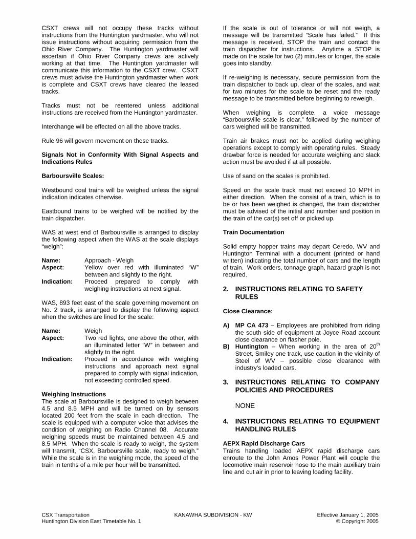
CSX Transportation KANAWHA SUBDIVISION - KW Effective January 1, 2005 Huntington Division East Timetable No. 1 © Copyright 2005
CSXT crews will not occupy these tracks without instructions from the Huntington yardmaster, who will not issue instructions without acquiring permission from the Ohio River Company. The Huntington yardmaster will ascertain if Ohio River Company crews are actively working at that time. The Huntington yardmaster will communicate this information to the CSXT crew. CSXT crews must advise the Huntington yardmaster when work is complete and CSXT crews have cleared the leased tracks. Tracks must not be reentered unless additional instructions are received from the Huntington yardmaster. Interchange will be effected on all the above tracks. Rule 96 will govern movement on these tracks. Signals Not in Conformity With Signal Aspects and Indications Rules Barboursville Scales: Westbound coal trains will be weighed unless the signal indication indicates otherwise. Eastbound trains to be weighed will be notified by the train dispatcher. WAS at west end of Barboursville is arranged to display the following aspect when the WAS at the scale displays “weigh”: Name: Approach - Weigh Aspect: Yellow over red with illuminated “W”
between and slightly to the right. Indication: Proceed prepared to comply with
weighing instructions at next signal. WAS, 893 feet east of the scale governing movement on No. 2 track, is arranged to display the following aspect when the switches are lined for the scale: Name: Weigh Aspect: Two red lights, one above the other, with
an illuminated letter “W” in between and slightly to the right.
Indication: Proceed in accordance with weighing instructions and approach next signal prepared to comply with signal indication, not exceeding controlled speed.
Weighing Instructions The scale at Barboursville is designed to weigh between 4.5 and 8.5 MPH and will be turned on by sensors located 200 feet from the scale in each direction. The scale is equipped with a computer voice that advises the condition of weighing on Radio Channel 08. Accurate weighing speeds must be maintained between 4.5 and 8.5 MPH. When the scale is ready to weigh, the system will transmit, “CSX, Barboursville scale, ready to weigh.” While the scale is in the weighing mode, the speed of the train in tenths of a mile per hour will be transmitted.
If the scale is out of tolerance or will not weigh, a message will be transmitted “Scale has failed.” If this message is received, STOP the train and contact the train dispatcher for instructions. Anytime a STOP is made on the scale for two (2) minutes or longer, the scale goes into standby. If re-weighing is necessary, secure permission from the train dispatcher to back up, clear of the scales, and wait for two minutes for the scale to be reset and the ready message to be transmitted before beginning to reweigh. When weighing is complete, a voice message “Barboursville scale is clear,” followed by the number of cars weighed will be transmitted. Train air brakes must not be applied during weighing operations except to comply with operating rules. Steady drawbar force is needed for accurate weighing and slack action must be avoided if at all possible. Use of sand on the scales is prohibited. Speed on the scale track must not exceed 10 MPH in either direction. When the consist of a train, which is to be or has been weighed is changed, the train dispatcher must be advised of the initial and number and position in the train of the car(s) set off or picked up. Train Documentation Solid empty hopper trains may depart Ceredo, WV and Huntington Terminal with a document (printed or hand written) indicating the total number of cars and the length of train. Work orders, tonnage graph, hazard graph is not required. 2. INSTRUCTIONS RELATING TO SAFETY
RULES Close Clearance: A) MP CA 473 – Employees are prohibited from riding
the south side of equipment at Joyce Road account close clearance on flasher pole.
B) Huntington – When working in the area of 20th Street, Smiley one track, use caution in the vicinity of Steel of WV – possible close clearance with industry’s loaded cars.
3. INSTRUCTIONS RELATING TO COMPANY
POLICIES AND PROCEDURES
NONE
4. INSTRUCTIONS RELATING TO EQUIPMENT HANDLING RULES
AEPX Rapid Discharge Cars Trains handling loaded AEPX rapid discharge cars enroute to the John Amos Power Plant will couple the locomotive main reservoir hose to the main auxiliary train line and cut air in prior to leaving loading facility.

CSX Transportation KANAWHA SUBDIVISION - KW Effective January 1, 2005 Huntington Division East Timetable No. 1 © Copyright 2005
Moving Clearance Implicated Shipments South Charleston Terminal 1) Cars entering the terminal from Locals will come into
the yard through No. 1 crossover and move from 101 to 102. Cars will then traverse west to the Pit Track and be stored on the designated L01 track.
2) Cars entering the yard from Yard Jobs will come through any clear yard track and be stored on L01 track.
3) Cars will be held on L01 track for safe storage until billing.
Huntington Terminal 1) If brought into the yard, any track, other than the
Running Track, is prohibited. The following tracks will be kept clear for the High and Wide to pass: a) Lower 6 b) Upper 6 c) Polish Pocket d) Upper 7
2) Yardmasters will advise inbound and outbound crews of possible close clearances between the Running Track and Lower 8, Upper 6, the Polish Pocket and Upper 7.
3) Preferred placement for the shipment is on the Main Line at CA 505.2, 2 West (HO or Kroger). The only accepted track in the yard is the Running Track throughout the length of the yard.
4) The method of protection will be crew briefings by the yardmaster and trainmasters and observation of equipment through the yard by the trainmaster or designee.
5. INSTRUCTIONS RELATING TO AIR BRAKE
AND TRAIN HANDLING RULES Calendar Day Inspection of Yard Locomotives Engineers/Remote Control Operators working 3rd shift yard assignments at South Charleston, WV will perform the calendar day inspection on their locomotives at the end of their tour of duty. These inspections will also include the slug unit. A separate 5001A is required for the slug unit. The hours of service law will not be exceeded to perform this inspection. All defects found must be reported to the yardmaster prior to going off duty. If the calendar day inspection has not been performed, due to the locomotives not being used on the 34d shift, etc., the engineer/remote control operator on the next shift the locomotives are used is responsible for completing this inspection. It is mandatory that each yard locomotive and slug be inspected each calendar day.
6. INSTRUCTIONS RELATING TO EQUIPMENT RESTRICTIONS
Huntington - Six-axle engines must not operate on the West Huntington West 15th Street Belt Line. 7. MISCELLANEOUS 7.1 Dock – Westbound trains enroute Bills Creek must
contact the South Charleston yardmaster before passing the WAS west end Dock for instructions. If unable to contact the yardmaster, train must STOP prior to reaching Garbage crossing until it is known that the train will continue to Bills Creek.
7.2 Instructions For Westbound Trains Terminating
At Russell, KY: Westward coal trains must report the following to the Coal Hump yardmaster when passing 19th Street, Ashland, KY: A) Condition of locomotives and direction of units B) Supplies, if needed C) HTD D) ETD E) Car count 7.3 Industrial Tracks 1. Winifrede IT 2. Bills Creek IT 3. Lexington Industrial Track A. Lexington industrial track is designated as excepted
track. B. Rule 96 will govern movements on the Lexington
industrial track. C. Equipment restrictions:
Location Equipment Restriction
Lexington IT Cars Exceeding Plate C Must Not Operate
Kentucky Electric Steel
Equipment Must Not Operate Beyond Car STOP
Sign
D. Crossing protection: All trains on the Lexington IT must approach highway grade crossings equipped with automatic grade crossing warning devices prepared to provide crossing protection in accordance with operating Rule 100-E due to rusty rail conditions.
E. Instructions for dwarf signal governing movement from the Lexington industrial track: Westbound trains moving from the Lexington IT to No. 2 track at NC Cabin must first receive permission from the AN dispatcher to reverse the hand-operated switch from the Lexington IT onto No. 2 track. Once the hand-operated switch indicates reverse to the AN dispatcher, the dispatcher will then line the dwarf signal on the Lexington IT for the affected train.
CSX Transportation KANAWHA SUBDIVISION - KW Effective January 1, 2005 Huntington Division East Timetable No. 1 © Copyright 2005
F. Track leased to Kentucky Electric Steel: A lease track agreement is in effect with Kentucky Electric Steel Corporation located on the Kanawha SD, Lexington IT, Coalton, KY, beginning 108 feet west of Route 966 grade crossing at Coalton, KY, MP 10.9, westbound to the west end of the Lexington IT track limit, Bridge 5313, MP 11.7.
Hand-Operated derail is placed at the point of the east entrance to Kentucky Electric Steel, lease track location 108 feet west of Route 966 grade crossing. Derails located on east and west ends of runaround track at Coalton, KY, are removed from service. Switches at both ends of the runaround track are to be left for straightaway movement on the Lexington IT and derail locked for normal position. CSXT crews will not occupy leased track at Coalton, KY, without instructions from the Coal Hump yardmaster who will not issue such instructions without authorization from Kentucky Electric Steel Corporation. Rule 96 will govern movement on leased trackage at Coalton, KY.
NOTES
NOTES

CSX Transportation KANAWHA SUBDIVISION - KW Effective January 1, 2005 Huntington Division East Timetable No. 1 © Copyright 2005
NOTES
NOTES
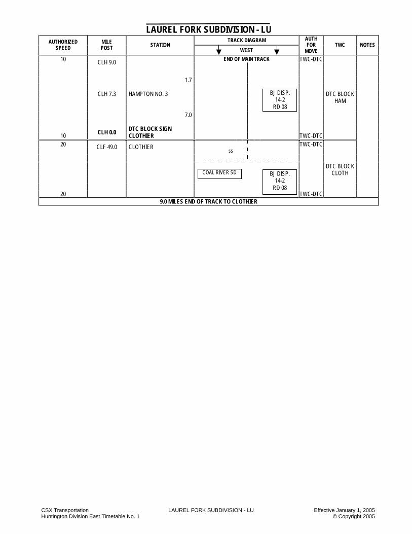
CSX Transportation LAUREL FORK SUBDIVISION - LU Effective January 1, 2005 Huntington Division East Timetable No. 1 © Copyright 2005
LAUREL FORK SUBDIVISION - LU TRACK DIAGRAM AUTHORIZED
SPEED MILE POST STATION
WEST
AUTH FOR
MOVE TWC NOTES
END OF MAIN TRACK 10 CLH 9.0 TWC-DTC
1.7 CLH 7.3 HAMPTON NO. 3 DTC BLOCK HAM 7.0
10 CLH 0.0 DTC BLOCK SIGN
CLOTHIER TWC-DTC 20 CLF 49.0 CLOTHIER
ss TWC-DTC
DTC BLOCK CLOTH
20 TWC-DTC 9.0 MILES END OF TRACK TO CLOTHIER
BJ DISP. 14-2
RD 08
COAL RIVER SD BJ DISP. 14-2
RD 08

CSX Transportation LAUREL FORK SUBDIVISION - LU Effective January 1, 2005 Huntington Division East Timetable No. 1 © Copyright 2005
LAUREL FORK SUBDIVISION SPECIAL INSTRUCTIONS
1. INSTRUCTIONS RELATING TO OPERATING RULES
Excepted Tracks The entire Laurel Fork SD is designated as excepted track. 2. INSTRUCTIONS RELATING TO SAFETY
RULES
NONE
3. INSTRUCTIONS RELATING TO COMPANY POLICIES AND PROCEDURES
NONE
4. INSTRUCTIONS RELATING TO EQUIPMENT HANDLING RULES
NONE
5. INSTRUCTIONS RELATING TO AIR BRAKE AND TRAIN HANDLING RULES
NONE
6. INSTRUCTIONS RELATED TO EQUIPMENT
RESTRICTIONS
NONE 7. MISCELLANEOUS
NONE
NOTES
NOTES
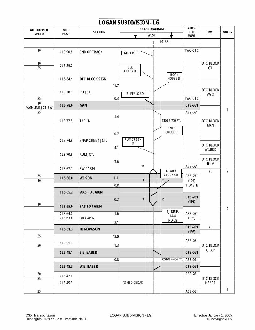
CSX Transportation LOGAN SUBDIVISION - LG Effective January 1, 2005 Huntington Division East Timetable No. 1 © Copyright 2005
LOGAN SUBDIVISION - LG TRACK DIAGRAM AUTHORIZED
SPEED MILE POST STATION
WEST
AUTH FOR
MOVE TWC NOTES
10 CLS 90.8 END OF TRACK
TWC-DTC
10 DTC BLOCK 25
CLS 89.0 GIL
CLS 84.1 DTC BLOCK SIGN 11.7 DTC BLOCK CLS 78.9 RH JCT. WYO
25 0.3 TWC-DTC 10
MAINLINE JCT SW CLS 78.6 MAN
CPS-261
35 ABS-261 1
1.4 CLS 77.5 TAPLIN SDG 5,700 FT. DTC BLOCK
MAN 0.7
CLS 74.8 SNAP CREEK JCT. 4.1
DTC BLOCK WILBER
CLS 70.8 RUM JCT.
3.6 ss ABS-261
DTC BLOCK RUM
CLS 67.1 SW CABIN 2
35 ABS-251 10
CLS 66.0 WILSON 1.1 1 2 (193)
0.8 1=W 2=E
YL
CLS 65.2 WAS FD CABIN
0.2 1 2 10
CPS-261 (193)
CLS 65.0 EAS FD CABIN 2
CLS 64.0 1.6 ABS-261 CLS 63.4 OB CABIN (193) 2.1 CPS-261 YL CLS 61.3 HENLAWSON
(193) 13.0 35
ABS-261 30
CLS 51.2 1.3 DTC BLOCK
CHAP
CLS 49.1 E.E. BABER
CPS-261
0.8 CSDG 4,486 FT. ABS-261
CLS 48.3 W.E. BABER
CPS-261
30 ABS-261 35
CLS 47.6 DTC BLOCK
CLS 45.3 (2) HBD-DEDAC HEART
35 ABS-261 1
ISLAND CREEK SD
BUFFALO SD
ROCK HOUSE IT
ELK CREEK IT
GILBERT IT
BJ DISP. 14-4
RD 08
NS RR
SNAP CREEK IT
RUM CREEK IT

CSX Transportation LOGAN SUBDIVISION - LG Effective January 1, 2005 Huntington Division East Timetable No. 1 © Copyright 2005
LOGAN SUBDIVISION - LG TRACK DIAGRAM AUTHORIZED
SPEED MILE POST STATION
WEST
AUTH FOR
MOVE TWC NOTES
35
1
ABS-261 30
CLS 44.4
4.6 DTC BLOCK
CLS 43.7 E.E. HEARTLAND
CPS-261 HEART
CSDG 10,731 FT. ABS-261
2.2
CLS 41.5 W.E. HEARTLAND
CPS-261
30 35
CLS 35.4 ABS-261
7.7 ss DTC BLOCK
CLS 33.8 E.E. RANGER
CPS-261 RANGER
CSDG 12333 FT. ABS-261
2.4
CLS 31.4 W.E. RANGER
CPS-261
ABS-261 35
CLS 29.8 30 DTC BLOCK
35 CLS 29.0
SALT CLS 21.0 (1)HBD-DEDAC CLS 6.6 TTB CLS 4.4 TTB
35 30
4.0 27.8 ABS-261
P F DTC BLOCK 30 30 SALT
3.6 MP 3.6
CPS-261
1
3.0 ABS-261 DTC BLOCK LOGAN NO. 1 LOGAN NO. 2 BRICK
30 30 ABS-261 87.2 MILES END OF TRACK TO MP CLS 3.6
STATION PAGE NOTES
NOTE 1: Signals displayed are in accordance with Signal Aspect Rules C1281 – C1298. NOTE 2: Movement against the current of traffic between FD Cabin and SW Cabin may be made on verbal permission of the BJ train dispatcher, who may withhold authority from westbound trains to occupy the Rum Block.
BJ DISP. 14-4
RD 08
KANAWHA SD
AN DISP. 20-3
RD 08

CSX Transportation LOGAN SUBDIVISION - LG Effective January 1, 2005 Huntington Division East Timetable No. 1 © Copyright 2005
LOGAN SUBDIVISION SPECIAL INSTRUCTIONS 1. INSTRUCTIONS RELATING TO OPERATING
RULES Spring Switches Location Normal
Position Facing Speed
When Springing
SW Cabin No. 1 Main E.E. Ranger SDG See Note 1 Main
35 10
Note 1: The Eastbound absolute dwarf signal for Ranger siding, located at the east end of Ranger MP CLS 33.8, is controlled by a switch key control box located on the north side of Ranger siding opposite the dwarf signal. Trains desiring to proceed east from Ranger siding to the main track through the spring switch at the east end of Ranger must first receive authority to enter the main track from the BJ dispatcher. The train crew must then operate the “Clear” key on the switch key control box. The dwarf signal should then display an aspect to proceed. Yard Limits A. Peach Creek: Eastbound trains must have yardmaster instructions for occupying to occupy the main track within this territory. Trains arriving Peach Creek Yard must contact the Peach Creek yardmaster for instructions prior to passing the following locations: Location Milepost Logan SD-Eastbound Trains CLS 60.0 Logan SD-Westbound Trains CLS 66.0 Island Creek SD-Westbound Trains CMC 0.8 Logan & Southern SD-Westbound Trains CME 0.0 Note: When no yardmaster is on duty, contact the BJ dispatcher for instructions. B. Crossover East End of Empty Yard and FD Cabin: Trains or engines must receive instructions from the Peach Creek yardmaster before occupying this track section. If no yardmaster is on duty, trains or engines must receive permission from the BJ dispatcher. C. Bypass Track: This track between the west end of the loaded yard and the switch to the engine pit lead must not be used without instructions from the yardmaster. If no yardmaster is on duty, this track section must not be used without permission from the BJ dispatcher.
Hand Brakes - Cars The following table lists exceptions to Operating Rule 103-D. These exceptions are the minimum number of hand brakes to be applied at that location. LOGAN SD Location Loaded Empty Comments
West Gilbert 10% 2 HB Per Cut Of Empties
Peach Creek Yard
3 HB 3 HB --
Fanco 10 HB 5 HB 45 Cars or Less
Fanco 20 HB 10 HB 46 Cars Or more
Holden 22 10 HB 5 HB
Each Cut Of Empties When Setting Cuts Of 30 Cars To The Mainline
Hutchinson 10 HB
When Running Around Train Preparing To Load
Emmett 15 HB On Long Track Of Empties
Emmett 8 HB On Empties Below The Crossing
Emmett 4 HB On Empties Above The Crossing
Pine Creek
10%
10 HB Per Empty Track
Between CLS 3.6 and CLS 61.3
5 HB 3HB
Phillips 18 HB 9 HB
All trains/cars left unattended
Normal Position of Switch MP CLS 41.5 – The inside hand throw switch at Heartland, MP CLS 41.5, will normally be lined for the stub end track. Permission of the BJ dispatcher must be received before unlocking and opening this switch. Radio Stations and Instructions HYCO (Peach Creek) yardmaster call in No. is 4. On-Track Equipment Instructions Between CLS 60.0 and CLS 67.4 instructions from the yardmaster must be obtained in addition to authority from the BJ dispatcher for on track equipment movements.

CSX Transportation LOGAN SUBDIVISION - LG Effective January 1, 2005 Huntington Division East Timetable No. 1 © Copyright 2005
Work Authority Instructions Between CLS 60.0 and CLS 67.4 before authority is issued for work force under Rule 707, a copy of the train message protecting same must be given to the Peach Creek yardmaster. 2. INSTRUCTIONS RELATING TO SAFETY
RULES Exceptions to Making A Safety STOP Employees will make the safety STOP as required by Safety Rule 2201 in all cases except at the locations described below: 1) Logan SD Snap Creek IT – When doubling up
loaded trains at Belva Mine. Crews doubling up loaded trains at the above listed locations must comply with safety rules and SOFA recommendations except for Safety Rule 2201 (safety stop) and must comply with the following: 1) Safety Rule 2001 - A job briefing must be conducted
in which the movement to be made is discussed. 2) Safety Rule 2201 - Employees must not ride to the
coupling. 3) Safety Rule 2101 - Employees must not mount or
dismount moving equipment. 4) Operating Rule 421 - When radios are used for
communication, crews must give clear and accurate car lengths for the movement to be made.
3. INSTRUCTIONS RELATING TO COMPANY POLICIES AND PROCEDURES
NONE
4. INSTRUCTIONS RELATING TO EQUIPMENT HANDLING RULES
NONE
5. INSTRUCTIONS RELATING TO AIR BRAKE
AND TRAIN HANDLING RULES NONE 6. INSTRUCTIONS RELATING TO EQUIPMENT
RESTRICTIONS
NONE 7. MISCELLANEOUS 7.1 Industrial Tracks A) Bandmill Industrial Track
1. Designated as excepted track between Bandmill Jct. MP 0.0 and end of track MP 1.8
B) Elk Creek Industrial Track
1. Designated as excepted track between Wylo MP 0.0 and Guyan 10 MP 2.8
C) Rum Creek Industrial Track
1. Designated as excepted track between Rum Jct. MP CLZ 0.0 and end of track MP CLZ 3.7
2. Leased to Bandmill Coal Company between MP CLZ 0.8 and CLZ 4.0
3. A switch point derail has been installed at MP CLZ 0.8.
D) Rock House Industrial Track
1. D.1 Designated as excepted track between RH Jct. MP 0.0 and end of track MP 3.4.
E) Snap Creek Industrial Track
1. Designated as excepted track between Snap Creek Jct. MP CLV 2.0 and end of track MP CLV 3.2.
2. Snap Creek IT is leased to Hampden Coal between MP CLV 0.0 and MP CLV 2.0.
3. Trains or engines occupying the Snap Creek IT between MP CLV 0.0 and MP CLV 2.0 will operate in accordance with Rule 96.
4. Trains or engines occupying the Snap Creek IT between MP CLV 0.0 and MP CLV 2.0 will not exceed 10 MPH.
5. Snap Creek IT between MP CLV 2.0 and MP CLV 3.2 is out of service.
F) Gilbert IT
NOTES

CSX Transportation LOGAN AND SOUTHERN SUBDIVISION - LS Effective January 1, 2005 Huntington Division East Timetable No. 1 © Copyright 2005
LOGAN AND SOUTHERN SUBDIVISION - LS TRACK DIAGRAM AUTHORIZED
SPEED MILE POST STATION
WEST
AUTH FOR
MOVE TWC NOTES
END OF MAIN TRACK 10 CME 11.5 SARAH ANN TWC-DTC DTC BLOCK
RAT 1.5 CME 10.2 STIRRAT 2.1 DTC BLOCK
10 RAT 25
CME 8.1 DTC BLOCK SIGN OMAR DTS BLOCK
1.0 OMAR CME 7.1 CHAUNCEY 3.3 CME 3.8 ROSSMORE 0.9 CME 2.9 MONAVILLE 2.9
25 CME 0.0 MONITOR JCT. TWC-DTC DTC BLOCK
OMAR 1,2,3
10 CMC 0.8 MONITOR JCT.
CPS-261 3
10 11.7 MILES SARAH ANN TO MONTIOR JCT.
STATION PAGE NOTES
NOTE 1: Rule ABS-261 are in effect for westward trains between CME 0.5 and Monitor Jct. NOTE 2: Trains entering or leaving the Logan and Southern SD at MP CME 0.0 operating in accordance with a signal indication requiring medium
speed will not exceed 15 MPH. NOTE 3: Signal aspects displayed are in accordance with signal aspect Rules C1281-C1298.
PINE CREEK SD
BJ DISP. 14-4
RD 08
ISLAND CREEK SD BJ DISP. 14-4
RD 08
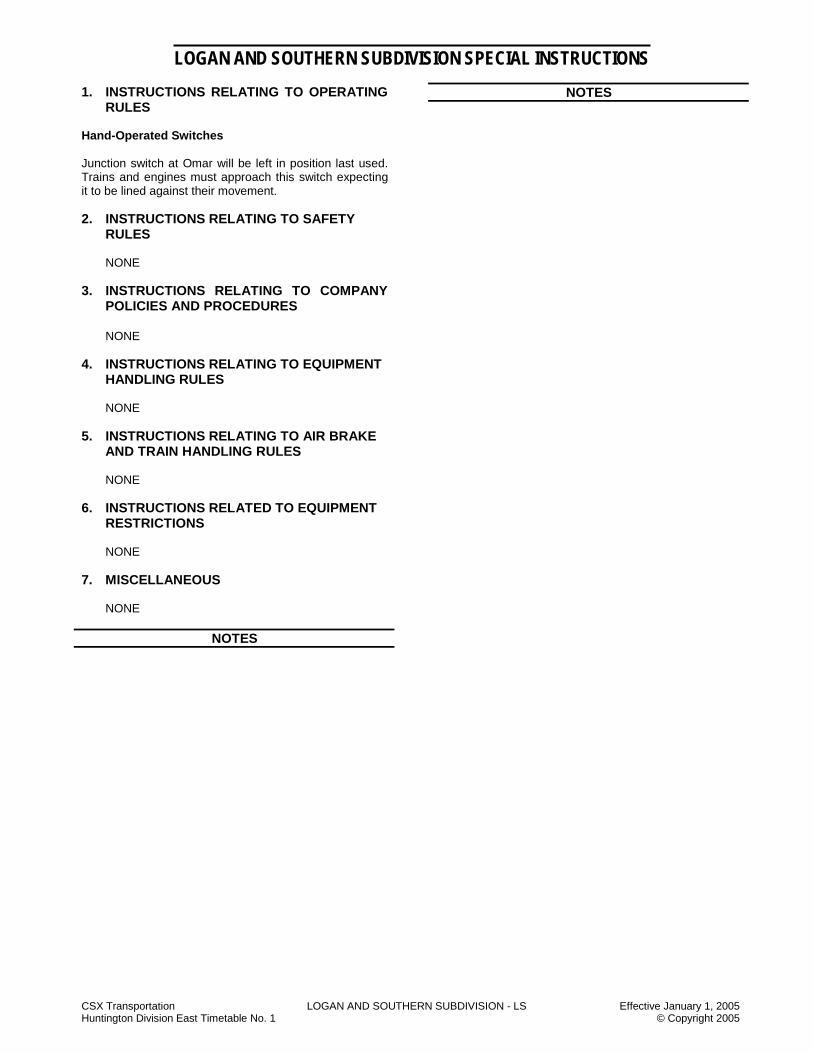
CSX Transportation LOGAN AND SOUTHERN SUBDIVISION - LS Effective January 1, 2005 Huntington Division East Timetable No. 1 © Copyright 2005
LOGAN AND SOUTHERN SUBDIVISION SPECIAL INSTRUCTIONS 1. INSTRUCTIONS RELATING TO OPERATING
RULES Hand-Operated Switches Junction switch at Omar will be left in position last used. Trains and engines must approach this switch expecting it to be lined against their movement.
2. INSTRUCTIONS RELATING TO SAFETY
RULES
NONE 3. INSTRUCTIONS RELATING TO COMPANY
POLICIES AND PROCEDURES NONE
4. INSTRUCTIONS RELATING TO EQUIPMENT HANDLING RULES
NONE
5. INSTRUCTIONS RELATING TO AIR BRAKE
AND TRAIN HANDLING RULES
NONE 6. INSTRUCTIONS RELATED TO EQUIPMENT
RESTRICTIONS
NONE 7. MISCELLANEOUS
NONE
NOTES
NOTES

CSX Transportation MARIETTA SUBDIVISION - MV Effective January 1, 2005 Huntington Division East Timetable No. 1 © Copyright 2005
MARIETTA SUBDIVISION - MV TRACK DIAGRAM AUTHORIZED
SPEED MILE POST STATION
WEST
AUTH FOR
MOVE TWC NOTES
96 1
BB 194.1 PARKERSBURG 2
20
BUS 0.0 BELPRE 0.0
20 7.5 96
25
BUS 3.0 TWC-DTC
4.0 5.0 DTC BLOCK
BUS 7.5 BAKELITE GRAVEL
BUS 8.9
4.2
BUS 9.0 DTC BLOCK SIGN
25
BUS 11.2
10 BUS 11.7 W. MARIETTA DTC BLOCK EQHR MARIETTA
25 BUS 12.4 HARMER
4453
BUS 15.4 DTC BLOCK SIGN
25 12.0 DTC BLOCK 10
BUS 20.0 HARMER
BUS 24.4 DTC BLOCK SIGN LOWELL DTC BLOCK
MONKEY
BUS 33.4 DTC BLOCK SIGN
BUS 33.8 DTC BLOCK BUS 33.9 WATERFORD WATER TWC-DTC
BUS 37.0 DTC BLOCK SIGN
YL BUS 37.6 RELIEF 38.0
193
10 BUS 38.0
END OF MAIN TRACK YL
STATION PAGE NOTES NOTE 1: Parkersburg Running Track between BA 383.6 (Green Street) and BB 189.6 (Porterfield), including the Ohio River Bridge (between
Parkersburg and Belpre), is operated in accordance with Rule 96. All train movements and OTE movements may be made with the verbal instructions of the Parkersburg yardmaster.
NOTE 2: Ohio River Bridge BB 194.1 to BA 384.0 is a Thru-Truss bridge.
CJ DISP. 14-5
RD 08
CJ DISP. 14-5
RD 08
0.7
UCC RR
PARKERSBURG RT
OHIO RIVER SD
PORTERFIELD BB 189.6
0.4
9.5
3.7

CSX Transportation MARIETTA SUBDIVISION - MV Effective January 1, 2005 Huntington Division East Timetable No. 1 © Copyright 2005
MARIETTA SUBDIVISION SPECIAL INSTRUCTIONS
1. INSTRUCTIONS RELATING TO OPERATING RULES
Excepted Track Marietta SD is designated as excepted track between BUS 20.0 and BUS 38.0. Junctions, Drawbridges, and Railroad Crossings At Grade
Railroad Crossings at Grade Location Railroad Position of Tilting Target
Bakelite UCC Horizontal for movement on CSX
State of Ohio – At railroad crossings and drawbridges, not equipped with approved interlocking, all trains or engines will STOP not less that 200 feet or more than 800 feet from the crossing or drawbridge, and will not proceed until the route is clear. Highway Crossings at Grade
Marietta, OH: 1. Approach Wood Street, Marietta, OH:
a) Prepared to STOP. Look out for tractor-trailers fouling crossing.
2. Approach Market Street: a) All trains must be sure crossing gates are down
and lights flashing before proceeding through crossing.
Hand Brakes - Cars The following table will be used for setting hand brakes on locomotives, cars, and trains left unattended on sidings, other tracks and main tracks. Unattended Hand-Brake Application Between Location/Milepost Loads Empties BUS 0.0 and BUS 38.0 20% 10% Hand-Operated Switches
The normal position of hand-operated switches on the Parkersburg Running Track and the Marietta SD will be lined for the Marietta SD. Use of Specified Tracks Marietta Running Track – Between BUS 0.0 and BUS 3.0, Rule 96 is in effect. Train and OTE movements may be made on verbal instructions of the Parkersburg yardmaster.
2. INSTRUCTIONS RELATING TO SAFETY
RULES Riding Equipment Due to close track centers, employees are not permitted to ride on the inside of the leading end of covered hoppers equipped with a solid steel bottom, and a safety handrail, which must have a handhold, while making a shoving movement at the following locations: BUS 2.0 -- Duggusa Corporation BUS 7.5 – Chevron Corporation BUS 13.0 – RJF Corporation Prior to starting the movement, the employee must be positioned inside the riding compartment of the covered hopper. 3. INSTRUCTIONS RELATING TO COMPANY
POLICIES AND PROCEDURES
NONE 4. INSTRUCTIONS RELATING TO EQUIPMENT
HANDLING RULES
NONE
5. INSTRUCTIONS RELATING TO AIR BRAKE AND TRAIN HANDLING RULES
NONE
6. INSTRUCTIONS RELATING TO EQUIPMENT
RESTRICTIONS
Location Equipment Restriction All industrial tracks except AEP Loop track
Six-axle units Must not operate
7. MISCELLANEOUS Parkersburg Running Track (Ohio River Bridge) Eastbound trains will not pass BB 194.1, Parkersburg (West approach Ohio River bridge) until they receive yarding instructions from the Parkersburg yardmaster.

CSX Transportation MOUNTAIN SUBDIVISION-MT Effective January 1, 2005 Huntington Division East Timetable No. 1 © Copyright 2005
MOUNTAIN SUBDIVISION - MT TRACK DIAGRAM AUTHORIZED
SPEED MILE POST STATION
WEST
AUTH FOR
MOVE TWC NOTES
DTC BLOCK 30 BA 178.9 VIADUCT JCT
CPS-261
BEALL
30 DTC BLOCK
CPS-261 BEALL
BA 179.5
ABS-251 1 BA 179.6
BEALL ST W-1, E-2
30 BA180.7
1 2 40
BA 183.3
DTC BLOCK 35
FIELD BA 183.6
40
BA 186.0
2 35
45
BA 187.0 MCKENZIE 12.0
190.0 191.0
BA 191.5 RAWLINGS
2
45 7.4 40
BA 192.0
BA 194.7 DTC BLOCK
BA 198.2 DAW 3
BA 198.9 TWENTY FIRST 40 35
BA 199.7 ABS-251
W-1, E-2 BA 200.4
YL
2.7 ABS-251(193) 1-W, 2-E
BA 200.5 INDUSTRIAL PARK 35 45
BA 201.0 NEW CREEK
BA 201.6 KEYSER ABS-251(193) 1.5 1-W, 2-E
BA 203.0 BA 203.1 WEST KEYSER (Z) BA 203.2
ABS-261 (193)
NO. 1 NO. 2
45 ABS- ABS- BA 204.9
261 251 40
(193) (193) BA 205.3
2-E 45
3.3 25
BA 206.2
BA 206.4 BA 206.6 PIEDMONT 4
ABS-251 (193)
1-W, 2-E YL
BA 207.1
INTERCHANGE TRACK 1.4 ABS-251 DTC BLOCK 1-W, 2-E GRADE
25
(1) DED #2 TRACK
EAST YARD
THOMAS SD (1)HBD-DED AC
CUMBERLAND TERMINAL SD
CI DISP. 14-5
RD 08
WEST YARD

CSX Transportation MOUNTAIN SUBDIVISION-MT Effective January 1, 2005 Huntington Division East Timetable No. 1 © Copyright 2005
MOUNTAIN SUBDIVISION - MT TRACK DIAGRAM AUTHORIZED
SPEED MILE POST STATION
WEST
AUTH FOR
MOVE TWC NOTES
25 ABS-251 25
BA 207.8 W.V. CENTRAL JCT 207.8 W-1, E-2
2.3 1 2
BA 210.1 WARNICKS CURVE (1) DED 5
BA 212.6 BOND DTC BLOCK
BA 214.8 FRANKVILLE GRADE
BA 216.2 HITCHCOCK TUNNEL 400 FT. 11 BA-219.0 ABTH 5559
25 30
BA 219.4 37 WATER STATION
BA 219.6 SWANTON
EAST
WAR
D T
RAI
NS,
SEE
NO
TE 1
1
30
BA 223.0
BA 223.4 ALTAMONT (WEST SWITCH)
30 224.3
45 BA 224.3
DTC BLOCK BA 229.4 ICEHOUSE SIDING 6.2 DEER
BA 229.6 MOUNTAIN LAKE PARK
45 30
BA 231.6 AGWAY SPUR ABS-251 DTC BLOCK
BA 232.7 OAKLAND (1) HBD-DEDAC W-1, E-2 HUT BA 240.7 RINARD 10,14 1.3 ABS-251 12 1-W CPS-261
BA 242.0 TERRA ALTA No. 1 No. 2 BA 243.3 BA242.5
30 242.5 ABS ABS BA 242.7
251 261 25
W-1 30
BA 250.8 10.5
BA 251.2 ABTH 5559
WES
TBO
UN
D T
RAI
NS
SEE
NO
TE 1
1
BA 252.3
MCMILLAN
CPS-261
DTC BLOCK ROD
(No. 1 ONLY)
BA 252.5 No. 1 No. 2
BA 252.2 1.4 ABS-261
253.2
ABS-251 2-E
DTC BLOCK MK
BA 253.9
CPS-261 13
ROWLESBURG .2
BA 254.1
BA 254.5 254.5 30 DTC BLOCK
25 BA 255.1
5.2 ABS-261 FILL ABTH 5559 BA 258.1 11
BA 258.9 258.9 6 25
EAST
WAR
D
TRAI
NS
S
EE N
OTE
11
BA 259.3 BLAZER
CPS-261
DTC BLOCK 30 BA 260.3 TUNNELTON ABS-261 TUNNEL
13.3
11.1
(1)HBD-DED AC
WVN RR
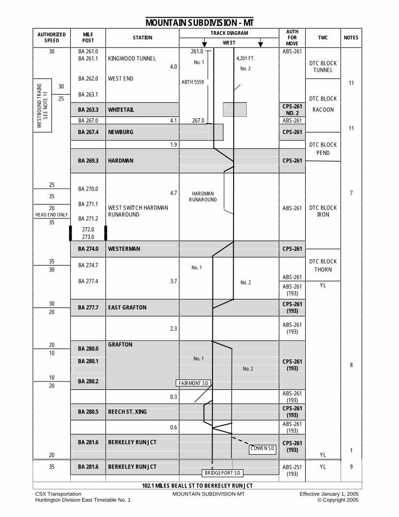
CSX Transportation MOUNTAIN SUBDIVISION-MT Effective January 1, 2005 Huntington Division East Timetable No. 1 © Copyright 2005
MOUNTAIN SUBDIVISION - MT TRACK DIAGRAM AUTHORIZED
SPEED MILE POST STATION
WEST
AUTH FOR
MOVE TWC NOTES
30 BA 261.0 261.0 ABS-261 BA 261.1 KINGWOOD TUNNEL 4.0
DTC BLOCK TUNNEL
BA 262.0 WEST END
ABTH 5559 11 30
25
BA 263.1 DTC BLOCK
BA 263.3 WHITETAIL CPS-261 NO. 2 RACOON
BA 267.0 4.1 267.0 ABS-261
WES
TBO
UN
D T
RAI
NS
SEE
NO
TE 1
1
11
BA 267.4 NEWBURG
CPS-261
1.9 DTC BLOCK PEND
BA 269.3 HARDMAN
CPS-261
25 BA 270.0
4.7 7 35
20 BA 271.1
ABS-261 HEAD END ONLY
35 BA 271.2
WEST SWITCH HARDMAN RUNAROUND
DTC BLOCK IRON
272.0 273.0
BA 274.0 WESTERMAN
CPS-261
35 DTC BLOCK 30
BA 274.7
THORN
ABS-261
BA 277.4 3.7 YL
ABS-261
(193)
30 20
BA 277.7 EAST GRAFTON CPS-261
(193)
2.3
ABS-261 (193)
20 10
BA 280.0
BA 280.1
8
10 20
BA 280.2
GRAFTON
CPS-261 (193)
0.3 ABS-261 (193)
BA 280.5 BEECH ST. XING
CPS-261
(193)
0.6 ABS-261 (193)
BA 281.6 BERKELEY RUN JCT
20
CPS-261 (193)
YL 1
35 BA 281.6 BERKELEY RUN JCT
YL 9
ABS-251 (193)
102.1 MILES BEALL ST TO BERKELEY RUN JCT
4,201 FT.
COWEN SD
HARDMAN RUNAROUND
No. 1
No. 2
No. 1 No. 2
FAIRMONT SD
No. 1
No. 2
BRIDGEPORT SD

CSX Transportation MOUNTAIN SUBDIVISION-MT Effective January 1, 2005 Huntington Division East Timetable No. 1 © Copyright 2005
STATION PAGE NOTES
NOTE 1: All signals are Signal Rules 1281-1298. NOTE 2: Rawlings No. 2 track - Eastbound trains activating detector will stop at dragging equipment detector sign at Loundes and communicate with the CI train dispatcher. NOTE 3: Trains making diverging movements from No. 2 track to No. 1 track at 21st that are stopped on the detector at BA 198.9 may proceed without performing a walking inspection of the train in accordance with Equipment Handling Rule 4304-B. NOTE 4: Diverging movements at Piedmont 15 MPH. NOTE 5: Warnicks Curve BA 210.1 - No 2 track - This detector will transmit a voice tone when dragging equipment is detected. Eastbound trains activating the detector must stop immediately using proper train handling techniques and then communicate with the CI train dispatcher. NOTE 6: Westbound trains, except Key Trains, receiving an indication other than dragging equipment from the detector at BA 258.1 are permitted to
proceed not exceeding 5 MPH until the rear of the train clears double track at BA 259.1. Eastbound trains, except Key Trains, receiving an indication other than dragging equipment from the detector at BA 258.1 are permitted to proceed not exceeding 5 MPH until the rear of the train clears the double track at BA 254.1.
NOTE 7: Trains operating on the Hardman runaround track are restricted to 10 MPH. NOTE-8: Authority for using “X” track must be obtained from the Grafton yardmaster. NOTE 9: Operating Rule 96 is in effect on the siding between Beech St. and Berkeley Run Jct. NOTE 10: The siding at Rinard is 3,900 feet. NOTE 11: For head end movement only the maximum authorized speed for all coal trains descending grades is 15 MPH at the following locations: Between BA 262.0 and BA 267.4 Between BA 259.3 and BA 255.1
Between BA 242.3 and BA 252.3 Between BA 223.0 and BA 207.8 If train speed cannot be maintained at or below the maximum speeds listed above, the train must be stopped immediately by making an
emergency brake application including the operation of the two-way EOT emergency toggle switch as quickly as possible. After stopping, sufficient hand brakes must be applied. Each car will be visually inspected to determine that the brakes are applied, piston travel is within standards and brake shoes are against each wheel. The train dispatcher must be immediately contacted. The train may only proceed after being authorized by the chief train dispatcher or a designated transportation manager. If needed, hand brakes may be left on the train to supplement train air brakes descending the remainder of the grade. Avoid leaving hand brakes on any empty car.
NOTE 12: Eastbound trains must not pass the eastbound Absolute signal at Terra Alta MP BA 242.3 on No. 2 track regardless of signal indication without prior permission from the ”CI” train dispatcher at Jacksonville. Once permission is received eastbound trains may proceed in accordance with signal aspect displayed.
Westbound trains must not pass the westbound absolute signal at Rinard MP BA 240.7 on No. 2 track regardless of signal indication without
prior permission of the “CI” train dispatcher at Jacksonville. Once permission is received, westbound trains may proceed in accordance with signal aspect displayed.
NOTE 13: M&K lead extends 2,600 feet. Authority for movement is Rule 96. NOTE 14: All movements from Rinard siding entering the CPS-261 territory at BA 246.7 in a westbound direction will only need permission from the CI
train dispatcher to move against the current of traffic.

CSX Transportation MOUNTAIN SUBDIVISION-MT Effective January 1, 2005 Huntington Division East Timetable No. 1 © Copyright 2005
MOUNTAIN SUBDIVISION SPECIAL INSTRUCTIONS
1. INSTRUCTIONS RELATING TO OPERATING RULES
Junctions, Drawbridges and Railroad Crossings at Grade Junctions The CI Train Dispatcher will control all movements on the interchange track from Piedmont, BA 206.6 to the Thomas Subdivision at West Virginia Central Jct. All movements will report clear. Highway Crossings at Grade Piedmont 1. Eastward trains using the Piedmont Connection Track
will ascertain that the crossing gates are in the down position before fouling road crossing at Piedmont.
2. Eastward trains using the Piedmont Connection Track
without signal indication must provide crossing protection with a member of the crew before fouling the road crossing at Piedmont.
Terra Alta 1. Eastward helpers on No. 1 Track that are to cut off at
Terra Alta must move east of white pole (located on the North side of No. 1 Track 869 Feet east of the westward intermediate signal) before returning west to activate the crossing protection on Main Street Crossing.
2. Eastward helpers on No. 2 Track that are to cut off at
Terra Alta must move east of the westbound dwarf signal before returning west to activate the crossing protection on Main Street Crossing.
Hand Brakes - Cars 1. The following chart applies to trains standing on a
heavy grade, locomotives attached and the crew stays with the train.
Note: Applies to trains that are stopped on heavy grades due to: 1. An undesired emergency. 2. To recharge the brake system. 3. Conductor and Engineer agree that hand brakes
are required to hold the train on grade.
Attended Hand Brake Application Between Location/Milepost Loads Empties BA 207.8 and BA 223.0 BA 242.5 and BA 251.2 BA 254.5 and BA 258.9 BA 261.0 and BA 267.0
45% 15%
Unattended Hand Brake Application Between Location/Milepost Loads Empties BA 179.5 and BA 207.2 5 HB Keyser Yard 12HB BA 207.2 and BA 207.8 15 HB
5 HB
BA 207.8 and BA 223.0 100% 30% BA 223.0 and BA 227.0 50% 20% BA 227.0 and BA 242.0 20% 5% BA 242.0 and BA 252.0 100% 30% BA 252.0 and BA 254.0 15% Rowlesburg Yard
30% 10HB
BA 254.0 and BA 259.0 100% 30% BA 259.0 and BA 262.0 20% 10% BA 262.0 and BA 267.0 100% 30% BA 267.0 and BA 269.3 50% 25% BA 269.3 and BA 281.6 10 HB 10% Grafton Terminal tracks M1W, W2N, X10, PS1 and B2M
5 HB
Grafton Terminal all other tracks 10% 5 HB
Hydraulic-Operated Switches Dewey Jct. Switch – Normal and Reverse code #2782 Conformation code #2700 Interlocking Offices
a. West Keyser (Z) is open continuously. b. Rowlesburg (MK) is open continuously.
Reverse Movements Helper engines on rear of eastbound trains on No. 2 track between McMillan and Terra Alta will communicate with the operator at Rowlesburg Tower or CI train dispatcher for permission to reverse direction to McMillan. 2. INSTRUCTIONS RELATING TO SAFETY
RULES Exceptions to Making A Safety Stop Employees will make the safety STOP as required by Safety Rule 2201 in all cases except at the locations described below: 1. BA 204.8 Rinard
Shoving train to recouple at Rinard when helper has been cut in.
2. BA 263.3 Whitetail
Making double with loads of coal at Whitetail Mine.

CSX Transportation MOUNTAIN SUBDIVISION-MT Effective January 1, 2005 Huntington Division East Timetable No. 1 © Copyright 2005
Crews working at the above listed locations must comply with safety rules and SOFA recommendations except for Safety Rule 2201 (safety stop) and must comply with the following:
1) Safety Rule 2001 - A job briefing must be conducted in which the movement to be made is discussed.
2) Safety Rule 2201 - Employees must not ride
to the coupling. 3) Safety Rule 2101 - Employees must not
mount or dismount moving equipment. 4) Operating Rule 421 - When radios are used
for communication, crews must give clear and accurate car lengths for the movement to be made.
3. INSTRUCTIONS RELATING TO COMPANY
POLICIES AND PROCEDURES
NONE 4. INSTRUCTIONS RELATING TO EQUIPMENT
HANDLING RULES Moving Clearance Implicated Shipments Grafton 1) All classification tracks are prohibited. 2) Instructions/Clearance Wires are received and
reviewed by the yardmaster for movement in the yard. 3) Main Track/ ‘X’ Track are the routes through the yard. 4) Cars are staged on the Hill Track protected by the
dispatcher with signal protection per instructions of the yardmaster.
5) No interchange. 6) The yardmaster protects movements in the yard. 5. INSTRUCTIONS RELATING TO AIR BRAKE
AND TRAIN HANDLING RULES NONE 6. INSTRUCTIONS RELATING TO EQUIPMENT
RESTRICTIONS Agway Spur - Engines will not go beyond the derail. Reacher cars must be used to make set offs and pick ups. Cars will be spotted just east of the derail. Industrial Park, Keyser, WV - Only single unit locomotives may occupy these tracks. Power/Roadmate units are considered as a single unit. Oakland – Crossover No. 2 Team Track - Only a single unit will move through the cross-over switch.
7. MISCELLANEOUS 7.1 Helper Engines a) Helper locomotives used to shove the rear of trains on
the Mountain Subdivision are limited to 18 axles of power.
If a helper consist has more than 18 axles of power, the helper must be cut into the train. The train dispatcher will determine the exact location to cut the helper in the train through communications with either the road foreman of engines or trainmaster.
Amperage equivalents for AC locomotives are measured in pounds of tractive effort. For the purpose of limiting power, the following will govern: 1000 amps = 120,000 lbs. per AC locomotive 800 amps = 90,000 lbs. per AC locomotive 650 amps = 72,000 lbs. per AC locomotive
b) Helper Locomotive – Between Hardman and
Terra Alta.
1) Manifest Trains – Helper engineers will limit power to 1,000 amperes loadmeter reading, using trainline power reduction as follows:
Manifest Loadmeter Restrictions
Number Axles Loadmeter Reading 12 No Limit 14 1,225 Amps 16 1,100 Amps 18 1,000 Amps 20 925 Amps 22 850 Amps 24 800 Amps
c) Rowlesburg Tower – Helper engineers
assisting trains off the siding at Rowlesburg, will use only sufficient power to start the train. After the train is started, the helper will not exceed the third throttle position until east of plant at McMillian.
d) Westbound Helpers – Helper engineers
assisting trains between Piedmont and Altamont on No. 1 track will endeavor to cut off before passing the westbound intermediate signal at BA 223.5 at Altamont and be governed by the train dispatcher’s instructions. If the helper passes the westbound intermediate signal, the train dispatchers permission must be granted before making a reverse movement, as provided by Operating Rule 272.
e) In-train Helper - When an in-train helper on
eastbound trains is to be cut out at Rinard, the helper will remain attached to the head portion of the train until clear of the signal governing movements into Rinard Siding.

CSX Transportation MOUNTAIN SUBDIVISION-MT Effective January 1, 2005 Huntington Division East Timetable No. 1 © Copyright 2005
f) Eastbound Helpers - Helper engineers will begin reducing the throttle in the vicinity of West End in order to have the throttle in Position #1 or less in the vicinity of Tunnelton Station. If further assistance is needed, the helper engineer will communicate with the head end engineer. This does not prevent the helper from shoving slack in at required locations.
g) Rowlesburg Helper Crews will have an EOT on
the locomotive consist attached to the coupler on the west end locomotive, and a brake stick inside the locomotive cab. The batteries will be removed from the EOT. Crews will keep charged batteries in the locomotive cab. If the EOT fails on the train that is being shoved, batteries on the EOT will be changed to prevent delay. It is the responsibility of the helper crew to return the EOT and brake stick to Rowlesburg when taking their power to Grafton for service. When deadheading to Grafton for power, the helper crew will take an EOT from Rowlesburg.
h) The Rowlesburg Helper Crew will inform the
Train Dispatcher 3 hours in advance anytime they will be used out of their terminal on a succeeding trip after being on duty 8 hours or having made 100 miles.
i) Rowlesburg Helper Fuel Reporting - Upon
Reporting for duty must report fuel readings of the helper consist to the CI dispatcher or operator at Rowlesburg.
7.2 Grade Operation
a) Stopped on Grades – When trains STOP while descending Seventeen Mile, Cheat River, Cranberry, and Newburg Grades, a proceed signal will not be given until the brake pipe is properly charged.
b) Hand brakes on Grades - If a train is stopped
for any reason on these grades and the locomotive air brake will not hold the train on the grade, a sufficient number of hand brakes must be set before the recharging procedure is initiated. Should the train separate, a sufficient number of hand brakes must be applied promptly to all portions of the train to hold each section on the grade.
c) Dynamic Brake Test - All trains originating in
Grafton will test dynamic braking on each locomotive in the consist being used to meet dynamic braking requirements before attaching it to the train. Locomotive consists on run through trains will test dynamic brakes before passing Westerman MP BA 274.0. Trains originating East of Westerman must make a running dynamic brake test at the first available location prior to Mt. Lake Park BA 229.8. It must be known that each locomotive being used to meet dynamic braking requirements is tested and in working condition before descending grades.
d) Descending Seventeen Mile Grade- Engineers of trains over 5,000 tons will reduce power to permit the train to pass the summit of the grade just East of the overhead bridge at Altamont, at no more than 10 MPH. As soon as train speed starts to increase, a minimum reduction of brake pipe pressure will be made and the dynamic brake then applied. Further reductions of the brake pipe pressure and modulation of the
Dynamic brake will be used to control train speed, not to exceed the specified speed between BA 223.0 and BA 207.8. If at any time train speed can not be maintained at or below the maximum speed permitted, the train must be stopped immediately by making an emergency brake application. After stopping, sufficient hand brakes must be applied. Each car will be visually inspected to determine that brakes are applied, piston travel is within standards, and brake shoes are against each wheel. The train dispatcher must be immediately contacted. The train may only proceed after being authorized by the chief train dispatcher or designated transportation manager. If needed, hand brakes may be left on the train to supplement train air brakes descending the remainder of the grade. Avoid leaving hand brakes on any empty cars.
e) Train Brakes - A running release of the train brakes will not be made on westbound loaded and mixed freight trains descending Cranberry grade between BA 242 at Terra Alta and BA 251 East of McMillian and descending Newburg grade between BA 261 at Kingwood Tunnel and BA 267 East of Newburg.
f) Cheat River and Seventeen Mile Grades – A
running release of the train brakes will not be made on Eastbound loaded and mixed freight trains descending Cheat River grade between BA 259 at Blaser and BA 254.4 at Rowlesburg and on Seventeen Mile Grade between BA 223.0 and BA 207.8 (head-end only).
g) Eastbound manifest trains - (without rear-end
helpers) will not exceed 5,000 tons ascending Newburg and Cranberry grades.
h) Eastbound Trains - Train make-up for
eastbound trains exceeding 5,000 tons from Grafton to Piedmont: Manifest trains – There must be at least 10 loaded cars on the head end of the train, each weighing at least 70 tons, none of which is 80 feet or longer. There must be at least 8 loaded cars on the rear end of the train, each weighing at least 70 tons, none of which is 80 feet or longer.
Manifest trains exceeding 7,000 tons must have eight loads of 70 tons or greater, none of which is 80 feet or greater, cut in with the helper at the point where tonnage does not exceed 7,000 tons.

CSX Transportation MOUNTAIN SUBDIVISION-MT Effective January 1, 2005 Huntington Division East Timetable No. 1 © Copyright 2005
i) Westbound Trains - between Cumberland and Grafton 1. Ascending Seventeen Mile grade and Cheat
Grade: Westbound trains (without rear end helpers), except solid empty hopper trains and solid bulk trains, will not exceed 3,500 tons ascending Seventeen Mile grade and 4,500 tons ascending Cheat River Grade. Solid empty hopper trains and solid bulk trains (without rear end helpers) will not exceed 4,800 tons. Merchandise trains over 5,000 tons will require a 2-unit helper ascending Seventeen Mile grade. One AC unit is considered as two units.
Note: Westbound solid empty coal car trains between Piedmont and Altamont will be limited to a maximum of 130 cars without a rear-end helper. If trains between 116 and 130 cars stall, no attempt will be made to restart the train without a rear-end helper. If a helper is not available, the train dispatcher must contact either the road foreman of engines or the trainmaster.
j) All westbound trains exceeding 100 cars -
must STOP at McMillan and Newburg and make a full service reduction of air brakes, if the air has been used previously to control the train on Cranberry or Newburg grades. All other empty trains making a running release must reduce brake pipe pressure at least 10 pounds. In either case, brake pipe exhaust must be stopped at least 20 seconds before brakes are released.
Eastbound Trains:
1. Grafton: Making a running dynamic brake test.
A) All trains originating in Grafton, WV, will make a running brake test of the dynamic brakes before being attached to the train.
B) Locomotive consist on the run through trains will test their dynamic brakes before passing Westerman, milepost BA 274.0
C) Trains originating east of Westerman, must make a running dynamic brake test at the first available location prior to Mountain Lake Park, milepost BA 229.8.
Running Dynamic Brake Test Procecdures Two unit consist With the locomotive consist moving, go to dynamic
brake and determine that the lead locomotive is operative and develops a retarding effect. After determining the lead locomotive is operative, isolate the lead unit and apply the dynamic brake to determine the trailing locomotive develops a retarding effect.
Three or more locomotives In reference to timetable special instructions, dynamic
brake requirements, the following may be required. With the locomotive consist moving, go to dynamic braking and determine that the lead locomotive is operative and producing a retarding effect. After determining the lead locomotive is operative, isolate the lead unit and the third unit and use the same procedure to determine the second unit develops a retarding effect. If axle count dictates a third unit is needed, the second locomotive must be isolated and it must be determined that the third unit develops a retarding effect. During this verification, an employee may position themselves on the appropriate unit to observe its retarding effect. If axle count dictates a third unit is needed, the second locomotive must be isolated and it must be determined that the third unit develops a retarding effect. During this verification, an employee may position themselves on the appropriate unit to observe its retarding effect and communicate results to the entire crew. If additional units are required, the same process will be used to test each additional unit.
7.3 Dynamic Brake Requirements Trains operating down Seventeen Mile, Cranberry, Cheat River and Newburg Grade at speeds of less than 20 mph will be governed as follows:
a) Less than 2,500 tons, a minimum of four axles operating in dynamic brake.
b) Between 2,501 and 3,500 tons, a minimum of six
axles operating in dynamic brake.
c) Between 3,501 and 6,000 tons, a minimum of eight axles operating in dynamic brake.
d) Between 6,001 and 8,000 tons, a minimum of
twelve axles operating in dynamic brake.
e) Over 8,001 tons, a minimum of sixteen axles operating in dynamic brake.
7.4 Instructions For Specific Location A. Beall Street – Eastbound trains held at Beall Street
must STOP west of the overhead bridge at BA 179.9 away from all residences, and report arrival time to CI train dispatcher
B. Placarded Cars - Westbound Manifest trains will not
be operated from Cumberland with a placarded car on the rear of the train without permission of the trainmaster or designated manager..
C. Engineer Qualification- When an engineer has not
operated over the Mountain Subdivision between Grafton and Cumberland (to include Seventeen Mile grade) for a period in excess of 6 months: The engineer must, prior to marking up, contact the Mountain Sub Road Foreman of Engines or his designee.

CSX Transportation MOUNTAIN SUBDIVISION-MT Effective January 1, 2005 Huntington Division East Timetable No. 1 © Copyright 2005
At this time they will discuss the physical characteristics, special instructions, train handling rules and their application pertaining to this territory as well as any other pertinent information. At that time it will be determined whether or not a pilot will be provided. The Road Foreman of Engines will arrange to ride with the engineer if deemed necessary for the purpose of re-qualification.
NOTES
NOTES
CSX Transportation MOUNTAIN SUBDIVISION-MT Effective January 1, 2005 Huntington Division East Timetable No. 1 © Copyright 2005
NOTES
NOTES

CSX Transportation NEW RIVER SUBDIVISION - NR Effective January 1, 2005 Huntington Division East Timetable No. 1 © Copyright 2005
NEW RIVER SUBDIVISION - NR TRACK DIAGRAM AUTHORIZED
SPEED MILE POST STATION
WEST
AUTH FOR
MOVE TWC NOTES
P F 1 2 1 2 ABS-261
DTC BLOCK
CA 354.6 MX CABIN BIG BEN 1,2,4
60
50
50
50
40
40
40
40 1 2
CPS-261
P F ABS-251 DTC BLOCK 1,2 1 2 1 2 1=W HINTON 50 50 40 40 2=E
CA 355.0
45 45 1 2
50 50 CA 355.3
2.2
50 50 40 45 25 25
CA 356.8 AVIS
HT MIDDLE TK 0.2
45 40
CA 357.0 HINTON ABS-251 25
25
1=W
CA 357.1 0.3 1 2 2=E DTC BLOCK 45
40
ABS-251 HINTON
CA 357.3 TOOL CAR 60
25 50
25 DTC BLOCK 60 50 50
CA 357.5 BARKS
1.7
CA 359.0 CW CABIN
CPS-261
60 60 ABS-261 CA 359.2 55 55
60 60 CA 359.4
360.0 360.5 (1) HBD-DEDAC DTC BLOCK 361.0 SAND 3.0 CA 362.0 RK CABIN
60 1 2 CA 363.1
55
CA 363.4
60 1 60 50 50 ABS-261
ALLEGHANY SD
AM DISP. 14-4
RD 08
EAST HINTON YARD
AM DISP. 14-8
RD 08
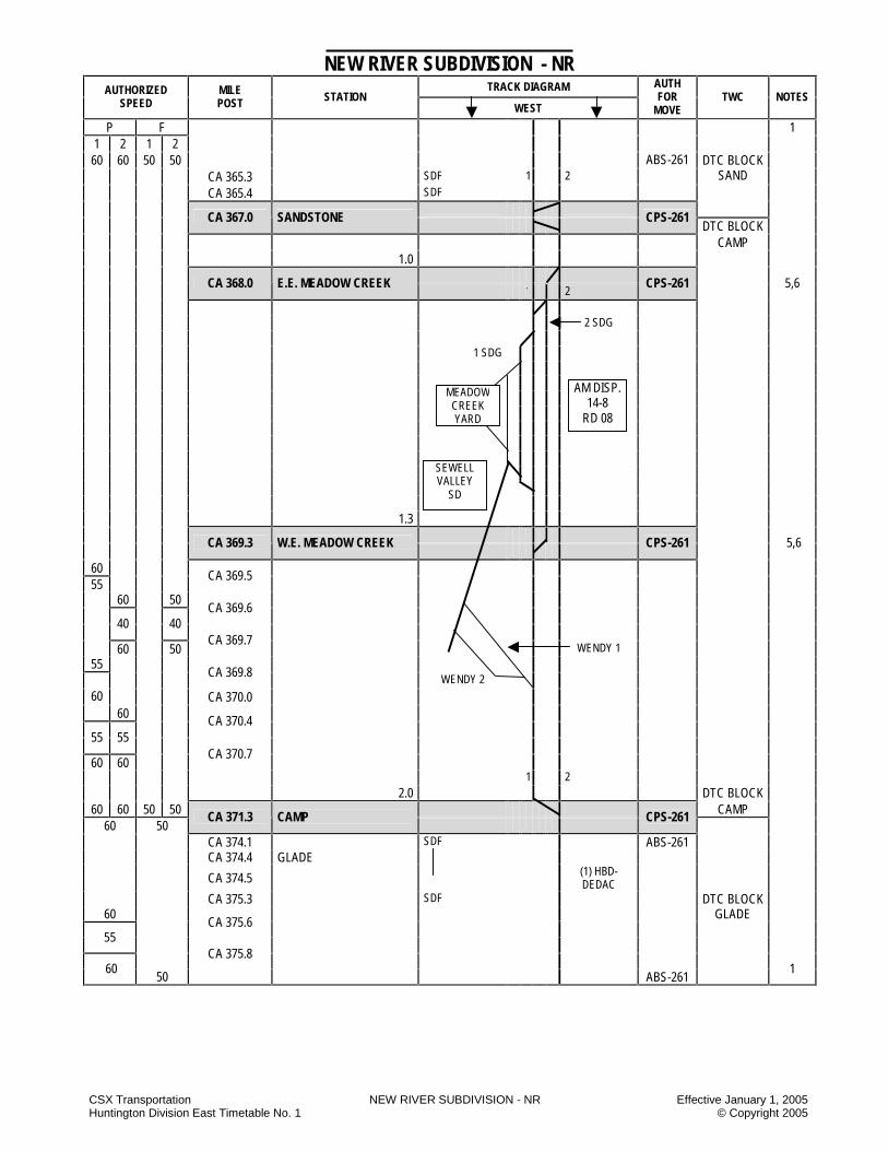
CSX Transportation NEW RIVER SUBDIVISION - NR Effective January 1, 2005 Huntington Division East Timetable No. 1 © Copyright 2005
NEW RIVER SUBDIVISION - NR TRACK DIAGRAM AUTHORIZED
SPEED MILE POST STATION
WEST
AUTH FOR
MOVE TWC NOTES
P F
1 2 1 2 1
60 60 50 50
CA 365.3 SDF 1 2 DTC BLOCK
SAND
CA 365.4 SDF
ABS-261
CA 367.0 SANDSTONE
CPS-261 DTC BLOCK
CAMP 1.0
CA 368.0 E.E. MEADOW CREEK 1 2
CPS-261
5,6
2 SDG 1 SDG 1.3
CA 369.3 W.E. MEADOW CREEK
CPS-261
5,6
60 55
CA 369.5
60 50
CA 369.6
40
40
60 50
CA 369.7 WENDY 1
55
CA 369.8 WENDY 2
CA 370.0 60 60
CA 370.4
55 55
60 60 CA 370.7
1 2 2.0 DTC BLOCK
60 60 50 50 CAMP 60 50
CA 371.3 CAMP
CPS-261
CA 374.1 SDF ABS-261 CA 374.4 GLADE
CA 374.5 (1) HBD-DEDAC
CA 375.3 SDF DTC BLOCK 60 GLADE
CA 375.6
55
CA 375.8 60
50 ABS-261 1
MEADOW CREEK YARD
SEWELL VALLEY
SD
AM DISP. 14-8
RD 08

CSX Transportation NEW RIVER SUBDIVISION - NR Effective January 1, 2005 Huntington Division East Timetable No. 1 © Copyright 2005
NEW RIVER SUBDIVISION - NR TRACK DIAGRAM AUTHORIZED
SPEED MILE POST STATION
WEST
AUTH FOR
MOVE TWC NOTES
P F 60 50 ABS-261
1
5.0
DTC BLOCK GLADE
CA 376.3 BACKUS CPS-261 DTC
BLOCK
60 50 QUINNY 50 35
CA 377.0 1 2
CPS-261
CA 377.2 E.E. QUINNIMONT
CA 378.0 NECK ABS 261 No.1
CPS 261 No.2
NECK 2.2
50 40
CA 378.5 QUINNIMONT
0.5 1 2 SDG
DTC BLOCK
QUINNY
CA 379.7 E.E. PRINCE
DTC
BLOCK
CPS-261
PRINCE
CA 380.0 W.E. PRINCE
CA 382.1 SDF CA 382.7 SDF
40
50 CA 383.3
ABS-261 DTC BLOCK
CA 383.7 SDF DUNFEE CA 383.9 SDF 8.3
CA 388.3 CLAREMONT
CPS-261
1 2
DTC BLOCK
STONE ABS-261
50 35 1
NEW YARD
PINEY CREEK
SD
AM DISP. 14-8
RD 08
OLD
YA
RD

CSX Transportation NEW RIVER SUBDIVISION - NR Effective January 1, 2005 Huntington Division East Timetable No. 1 © Copyright 2005
NEW RIVER SUBDIVISION - NR TRACK DIAGRAM AUTHORIZED
SPEED MILE POST STATION
WEST
AUTH FOR
MOVE TWC NOTES
P F
1 50 35
1.1 1 2
CA 389.4 WVS RR DTC BLOCK 1.4 STONE
50 35 25 25 DTC BLOCK
CA 391.1 THURMOND
CPS-261
RUSH
CA 391.2 E.E. RUSH RUN CPS-261
25 25 50 35
CA 391.5 1.3 CSDG 7,440FT.
CA 392.5 W.E. RUSH RUN
CPS-261
ABS-261 50
CA 394.5
45
50 CA 394.7
CA 397.0 (1) HBD-DEDAC
50
CA 397.1 40
50
CA 397.4 5.0 ABS-261 DTC BLOCK
RUSH
CA 397.5 SEWELL
CPS-261 DTC BLOCK
50 35 ABS-261 SEWELL CA 398.2 TTB 1 2 10
2 TK 10
2 TK CA 398.4
50 35
1 2 1 2 40 35 30
CA 399.0 50
CA 399.1 40
CA 400.6 50
SDF 1 TK 40
CA 402.5
CA 402.9 SDF 1 TK 1 2
40 40 35 30 ABS-261‘ DTC BLOCK
SEWELL 1
AM DISP. 14-8
RD 08

CSX Transportation NEW RIVER SUBDIVISION - NR Effective January 1, 2005 Huntington Division East Timetable No. 1 © Copyright 2005
NEW RIVER SUBDIVISION - NR TRACK DIAGRAM AUTHORIZED
SPEED MILE POST STATION
WEST
AUTH FOR
MOVE TWC NOTES
P F 1 2 1 2
DTC BLOCK SWEWLL 1
40 40 35 30 ABS-261
1 2
CPS ABS 261 261
CA 403.0 E.E. FAYETTE NO.1 NO.2
2
CA 403.0 S. FAYETTE 40 CSDG 6,317 FT. ABS-261 50
CA 403.6 1.3
CPS ABS 261 261
CA 404.3 W.E. FAYETTE NO.1 NO.2
2
50 ABS-261
CA 405.8 45
CA 406.1 50
35
CA 408.5
25 10 CA 408.8 TTB
CA 408.9 50 40 35 30 CA 409.0
3.7 50 35
40 CA 409.1
1.7 ABS-261 DTC BLOCK SEWELL
CA 410.8 COTTON HILL
CPS-261
3
40 DTC BLOCK 45
CA 414.1 4.2 ABS-261
HAWK
CA 414.8 GU CABIN
CPS-261
0.3
CA 415.1 E.E. GAULEY
CPS-261
3
CA 415.5 0.6 CSDG 2,308 FT.
SDF DTC BLOCK GAME
CA 415.6 W.E. GAULEY
CA 416.0 SDF ABS-261 45 50
CA 418.1 2.3 1 2
CA 418.3 KANAWHA FALLS
CPS-261
50 35 ABS-261 65 50
CA 419.0
CA 419.8 SDF 420.0 420.3 SDF 420.5 3.0 (2) HBD-DEDAC DTC BLOCK 421.0 DEEP CA 421.3 0.8 2 CA 422.1
65 50 ABS-261
1
AM DISP. 14-8
RD 08
GAULEY SD
NS

CSX Transportation NEW RIVER SUBDIVISION - NR Effective January 1, 2005 Huntington Division East Timetable No. 1 © Copyright 2005
NEW RIVER SUBDIVISION - NR TRACK DIAGRAM AUTHORIZED
SPEED MILE POST STATION
WEST
AUTH FOR
MOVE TWC NOTES
P F 65 50
1
ABS-261
1.4 DTC BLOCK
DEEP
CA 423.5 MT. CARBON
CPS-261
65 1 2 ABS-261
CA 423.9 55
65
CA 424.1
2.0 CA 425.5 EAGLE DTC BLOCK EAGLE
65
CA 426.6 60
CA 426.7 65
50 CA 426.9
2.4 1 2 ABS-261 30 30
CA 427.9 MONTGOMERY CPS-261 DTC BLOCK
1
PRATT P F
30 30 ABS-261 1
DTC BLOCK CA 428.2
PRATT
30 30 ABS-261 72.9 MILES MX CABIN TO MONTGOMERY
STATION PAGE NOTES
NOTE 1: Signals displayed are in accordance with Signal Aspect Rules C1281 – C1298. NOTE 2: Rules ABS-261 are in effect on the following tracks:
A) Switching lead MX Cabin. B) Fayette siding off No. 1 track. C) Deepwater siding.
NOTE 3: Between MP CA 411.6 and MP CA 415.2 trains in excess of 14,000 tons must not exceed 25 MPH. NOTE 4: Between MP CA 280.8 and MP CA 354.6, trains in excess of 14,000 tons must not exceed 35 MPH. NOTE 5: Do not exceed 10 MPH on No. 2 Siding between CA 368.1 and CA 369.3 NOTE 6: Rules ABS-261 are in effect on Meadow Creek Siding.
AM DISP. 14-8
RD 08
AN DISP. 20-3
RD 08
KANAWHA SD

CSX Transportation NEW RIVER SUBDIVISION - NR Effective January 1, 2005 Huntington Division East Timetable No. 1 © Copyright 2005
NEW RIVER SUBDIVISION SPECIAL INSTRUCTIONS 1. INSTRUCTIONS RELATING TO OPERATING RULES Highway Crossings at Grade Thurmond, WV MP CA 390.9 When cars are left standing on the lead at Thurmond, they must be left east of the passenger station platform to prevent unnecessary activation of crossing protection devices. North Fayette, WV MP CA 404.2 All trains operating in the siding at North Fayette will be governed by Rule 100-J when providing crossing protection at the Route 82 road crossing due to rusty rail conditions. Use Of Specified Tracks Hinton – Trains approaching Hinton Yard at either MX or RK Cabin will contact the Hinton yardmaster in Huntington for yarding instructions. If unable to reach yardmaster, trains will contact the AM train dispatcher for yarding instructions. 2. INSTRUCTIONS RELATING TO SAFETY
RULES Close Clearance: Employees are prohibited from riding the side of equipment at the following locations: A) Hinton – Between No. 7 and No. 8 tracks in East
yard, when adjunct track is occupied with equipment. Close clearance signs are not displayed.
B) Meadow Creek – Between Wendy No. 2 track and retaining wall north side, 20 car lengths east of Wendy derail.
C) Quinnimont – Between Old yard No. 1 and Old yard No. 2 tracks, 30 car lengths from west end.
3. INSTRUCTIONS RELATING TO COMPANY
POLICIES AND PROCEDURES
NONE 4. INSTRUCTIONS RELATING TO EQUIPMENT
HANDLING RULES
NONE 5. INSTRUCTIONS RELATING TO AIR BRAKE
AND TRAIN HANDLING RULES
NONE
6. INSTRUCTIONS RELATING TO EQUIPMENT
RESTRICTIONS
NONE 7. MISCELLANEOUS 7.1 Meadow Creek: 1. Cars left standing on all tracks must be left west of
the white post located 160 feet west of industrial road crossing.
2. Cars left standing on No. 1 main track west of Wendy switch MP CA 371.0 must have at least one set of trucks left standing between the switch point and the white post located 90 feet west of the switch.
Hand Brakes - Cars LOCATION LOADED EMPTY COMMENTS CA 354.6-CA 392.5 5% 2% minimum
NOTES

CSX Transportation NEW RIVER SUBDIVISION - NR Effective January 1, 2005 Huntington Division East Timetable No. 1 © Copyright 2005
NOTES
NOTES

CSX Transportation NORTH MOUNTAIN SUBDIVISION - MU Effective January 1, 2005 Huntington Division East Timetable No. 1 © Copyright 2005
NORTH MOUNTAIN SUBDIVISION - MU TRACK DIAGRAM AUTHORIZED
SPEED MILE POST STATION
WEST
AUTH FOR
MOVE TWC NOTES
P F ABS-261 DTC BLOCK GORDON
50 40
CA 179.6 RIVANNA RIVER BRIDGE CPS-261
UN
DER
10,
000
TON
S O
VER
10,
000
TON
S
CPS-261 (193)
YL 1
45 20 20 CA 179.6 RIVANNA RIVER BRIDGE
45 20 20 ABS-261 15 10 10
CA 180.1 2.7 (193)
CA 182.3 JC CABIN
CPS-261 (193)
0.9 ABS-261 (193)
15 YL
45 CA 183.1 MP 183
CPS-261
(193) ABS-261 10 10 40 25
CA 183.9
45 5.9 DTC BLOCK 40
CA 185.1 FARM
40 60
CA 188.6
3,4
CA 189.0 EAST IVY
CPS-261
0.9 SSDG 4,580 FT. ABS-261
CA 189.9 WEST IVY
CPS-261 3, 4
60 ABS-261 55
CA 190.1 DTC BLOCK
CROZET
55 5.9 60
CA 190.7
191 192
60 40 25 ABS-261
AM DISP. 14-5
RD 08
WASHINGTON SD
AM DISP. 14-5
RD 08
NS RR

CSX Transportation NORTH MOUNTAIN SUBDIVISION - MU Effective January 1, 2005 Huntington Division East Timetable No. 1 © Copyright 2005
NORTH MOUNTAIN SUBDIVISION - MU TRACK DIAGRAM AUTHORIZED
SPEED MILE POST STATION
WEST
AUTH FOR
MOVE TWC NOTES
P F 60 40 25 CA 192.2 192.2 ABS-261 4
CA 194.1 EAST CROZET
CPS-261
SSDG 3,940 FT. ABS-261 ABTH 5559 DTC BLOCK 4
CA 194.8 WEST CROZET
CPS-261
CROZET
60 40 9.0 ABS-261 30 25
CA 196.7
CA 197.6 3 4
CA 203.3 EAST AFTON
CPS-261
DTC BLOCK CA 203.9 203.9 AFTON SSDG 4,240 FT. ABS-261
4
CA 204.1 WEST AFTON
CPS-261
ABS-261
30 25 40
CA 204.2
40 CA 204.7 BLUE RIDGE TUNNEL 35
CA 205.4
3.3 ABS-261
CA 207.1 BASIC
CSP-261
ABS-261 DTC BLOCK AFTON
CA 207.2 1.6 DTC BLOCK
WAYNE 35 40
CA 207.7
ABS-261
40 60
CA 208.7 EAST WAYNESBORO
CPS-261
ABS-261
CA 209.5 WEST WAYNESBORO
CPS-261
8.0 ABS-261
DTC BLOCK WAYNE 4
CA 217.1 EAST BRAND
CPS-261
60 40 25 SSDG 5,640 FT. ABS-261
DTC BLOCK BRAND
NS RR

CSX Transportation NORTH MOUNTAIN SUBDIVISION - MU Effective January 1, 2005 Huntington Division East Timetable No. 1 © Copyright 2005
NORTH MOUNTAIN SUBDIVISION - MU TRACK DIAGRAM AUTHORIZED
SPEED MILE POST STATION
WEST
AUTH FOR
MOVE TWC NOTES
P F 60 40 25
ABS-261
4
CA 218.1 WEST BRAND
CPS-261
DTC BLOCK BRAND
60
CA 218.2
50 1.9 ABS-261
60 CA 218.5
CA 219.4 MP 219 CPS-261 2
60 40 25 25
CA 220.7 1.4 ABS-261
CA 220.8 STAUNTON CPS-261 ABS-261
25 25 1.4 50 40 30
CA 221.5
CA 222.2 MP 222 CPS-261
50 2.0 60
CA 223.3
ABS-261
CA 223.8 EAST LA GRANGE
CPS-261
ABS-261 DTC BLOCK BRAND
WES
TBO
UN
D
EAST
BOU
ND
CA 224.0
DTC BLOCK NORTH
60 40 30 60 40
CA 224.2 CSDG 3,690 FT.
CA 224.5 WEST LA GRANGE
CPS-261
60 9.8
CA 225.2
55
60 CA 226.7
CA 227.1 DTC BLOCK 2
60 40 25 ABS-261 NORTH
BB RR
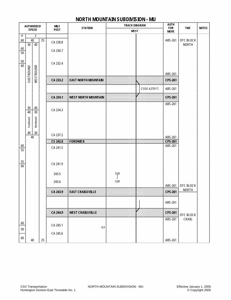
CSX Transportation NORTH MOUNTAIN SUBDIVISION - MU Effective January 1, 2005 Huntington Division East Timetable No. 1 © Copyright 2005
NORTH MOUNTAIN SUBDIVISION - MU TRACK DIAGRAM AUTHORIZED
SPEED MILE POST STATION
WEST
AUTH FOR
MOVE TWC NOTES
P F 60 40 25 ABS-261 DTC BLOCK 30 40
CA 228.8 NORTH
60 50
CA 230.7
50 60
CA 232.4
ABS-261
CA 233.2 EAST NORTH MOUNTAIN
CPS-261
CSDG 4,370 FT. ABS-261
EAST
BOU
ND
WES
TBO
UN
D
CA 234.1 WEST NORTH MOUNTAIN
CPS-261
ABS-261 30 40 40 30
CA 234.3
East
boun
d
Wes
tbou
nd
40 30 40
CA 237.2 ABS-261
CS 242.8 FORDWICK CPS-261 60 ABS-261 55
CA 241.5
55 60
CA 241.9
243.5 SDF 243.6
SDF
ABS-261 DTC BLOCK NORTH
CA 243.9 EAST CRAIGSVILLE
CPS-261
ABS-261
CA 244.9 WEST CRAIGSVILLE
CPS-261
DTC BLOCK ABS-261 CRAIG
60
CA 245.1 4.9 50
CA 245.6
60 40 25 ABS-261
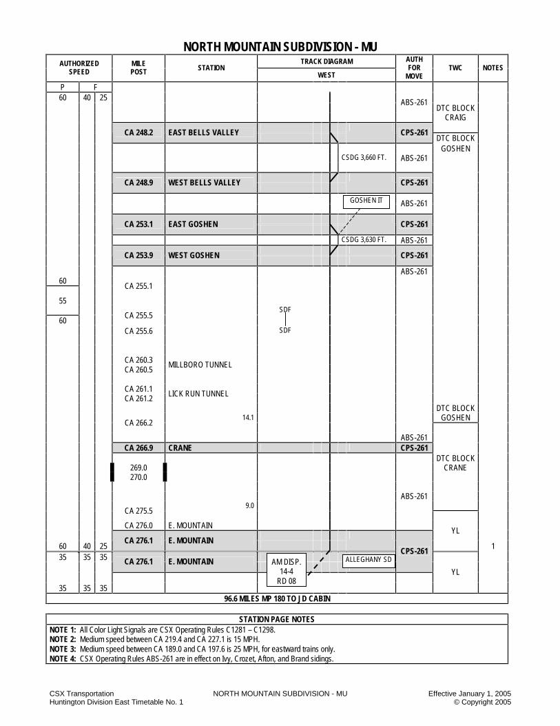
CSX Transportation NORTH MOUNTAIN SUBDIVISION - MU Effective January 1, 2005 Huntington Division East Timetable No. 1 © Copyright 2005
NORTH MOUNTAIN SUBDIVISION - MU TRACK DIAGRAM AUTHORIZED
SPEED MILE POST STATION
WEST
AUTH FOR
MOVE TWC NOTES
P F 60 40 25
ABS-261 DTC BLOCK
CRAIG
CA 248.2 EAST BELLS VALLEY
CPS-261
DTC BLOCK GOSHEN CSDG 3,660 FT. ABS-261
CA 248.9 WEST BELLS VALLEY
CPS-261
ABS-261
CA 253.1 EAST GOSHEN
CPS-261
CSDG 3,630 FT. ABS-261
CA 253.9 WEST GOSHEN
CPS-261
ABS-261 60
CA 255.1
55 SDF
60 CA 255.5
CA 255.6
SDF CA 260.3 CA 260.5
MILLBORO TUNNEL CA 261.1 CA 261.2
LICK RUN TUNNEL DTC BLOCK 14.1 GOSHEN
CA 266.2
ABS-261 CA 266.9 CRANE CPS-261 DTC BLOCK 269.0 CRANE 270.0 ABS-261 9.0
CA 275.5
CA 276.0 E. MOUNTAIN YL
60 40 25
CA 276.1 E. MOUNTAIN
1 35 35 35
CA 276.1 E. MOUNTAIN
CPS-261
35 35 35
YL
96.6 MILES MP 180 TO JD CABIN
STATION PAGE NOTES
NOTE 1: All Color Light Signals are CSX Operating Rules C1281 – C1298. NOTE 2: Medium speed between CA 219.4 and CA 227.1 is 15 MPH. NOTE 3: Medium speed between CA 189.0 and CA 197.6 is 25 MPH, for eastward trains only. NOTE 4: CSX Operating Rules ABS-261 are in effect on Ivy, Crozet, Afton, and Brand sidings.
AM DISP. 14-4
RD 08
ALLEGHANY SD
GOSHEN IT
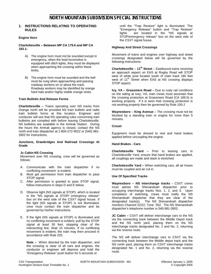
CSX Transportation NORTH MOUNTAIN SUBDIVISION - MU Effective January 1, 2005 Huntington Division East Timetable No. 1 © Copyright 2005
NORTH MOUNTAIN SUBDIVISION SPECIAL INSTRUCTIONS
1. INSTRUCTIONS RELATING TO OPERATING RULES
Engine Horn Charlottesville – Between MP CA 179.6 and MP CA 183.1:
A) The engine horn must not be sounded except in emergency, when the lead locomotive is equipped with ditch lights, they must be displayed when approaching the crossing within these limits.
B) The engine horn must be sounded and the bell
must be rung when approaching and passing roadway workers on or about the track. Roadway workers may be identified by orange hard hats and/or highly visible orange vests.
Train Bulletin And Release Forms Charlottesville – Trains operating over NS tracks from Orange north will be provided NS train bulletin and radio train bulletin forms at this location. Engineer and conductor will see that NS operating rules concerning train bulletins are complied with before leaving Charlottesville. NS bulletins are available in the Amtrak Station. During the hours the Amtrak agency is closed, contact the NS north end train dispatcher at 1-800-272-9522 or (540) 981-3902 for instructions. Junctions, Drawbridges And Railroad Crossings At Grade Jc Cabin-NS Crossing Movement over NS crossing, crew will be governed as follows: A. Communicate with the train dispatcher if no
conflicting movement is evident. B. Must get permission from train dispatcher to pass
STOP signal. C. After permission is granted to pass STOP signal,
follow instructions in steps D and E below. D. Observe light (NS signals at STOP), which is located
in the “NS signals at STOP/ emergency release” box on the west side of the CSXT signal house. If the light (NS signals at STOP) is not illuminated, crew must contact the train dispatcher and be governed by his/her instructions.
E. If the light (NS signals at STOP) is illuminated and
no conflicting movement is evident, pull by the STOP signal at least 30 feet, stopping clear of the intersecting line. Wait 10 minutes. If no conflicting movement is evident, the train may then proceed in accordance with Rule 225.
Note – When directed by the train dispatcher, and the crossing is clear of all cars and engines, the conductor or engineer will depress and hold the “Emergency Release” push button for 5 seconds or
until the “Trap Restore” light is illuminated. The “Emergency Release” button and “Trap Restore” lights are located in the “NS signals at STOP/emergency release” box on the west side of the CSXT signal house.
Highway And Street Crossings
Movement of trains and engines over highway and street crossings designated below will be governed by the following instructions:
Charlottesville – 11th Street – Eastbound trains receiving an approach aspect on EAS at Rugby Road will STOP west of white post located south of main track 180 feet west of 11th Street when EAS at NS crossing displays STOP aspect. Ivy, VA – Grassmere Road – Due to rusty rail conditions on the siding at Ivey, VA, train crews must ascertain that the crossing protection at Grassmere Road (CA 189.5) is working properly. If it is seen that crossing protection is not working properly then be governed by Rule 100-J Waynesboro – King Avenue – The crossing must not be blocked by a standing train or engine for more than 5 minutes.
Crozet
Equipment must be shoved to rest and hand brakes applied before uncoupling the engine.
Hand Brakes - Cars Charlottesville Yard – Prior to leaving cars in Charlottesville Yard, ensure that hand brakes are applied, all couplings are made and slack is stretched. Charlottesville Yard – When switching cars, all air hoses must be coupled and air cut in. Use Of Specified Tracks Waynesboro – NS Interchange tracks - CSXT crews must advise NS Shenandoah dispatcher prior to occupying interchange tracks Nos. 1, 2, and 3. Upon completion of switching, crews must notify the NS Shenandoah dispatcher that they are clear of the designated track(s). The NS Shenandoah dispatcher monitors Channel 22/22, Tone 552. The NS Shenandoah dispatcher’s telephone number is 540-981-3902. JC Cabin – CSXT will deliver interchange cars to the NS via the connecting track between the Middle Depot track and the NS north yard, placing them on the NS interchange tracks designated No. 1 and No. 2, returning via the reverse route. The NS will deliver interchange cars to CSXT via the connecting track between the Middle depot track and the NS north yard, placing them on CSXT interchange tracks designated No. 1 and No. 2, returning via the reverse route.
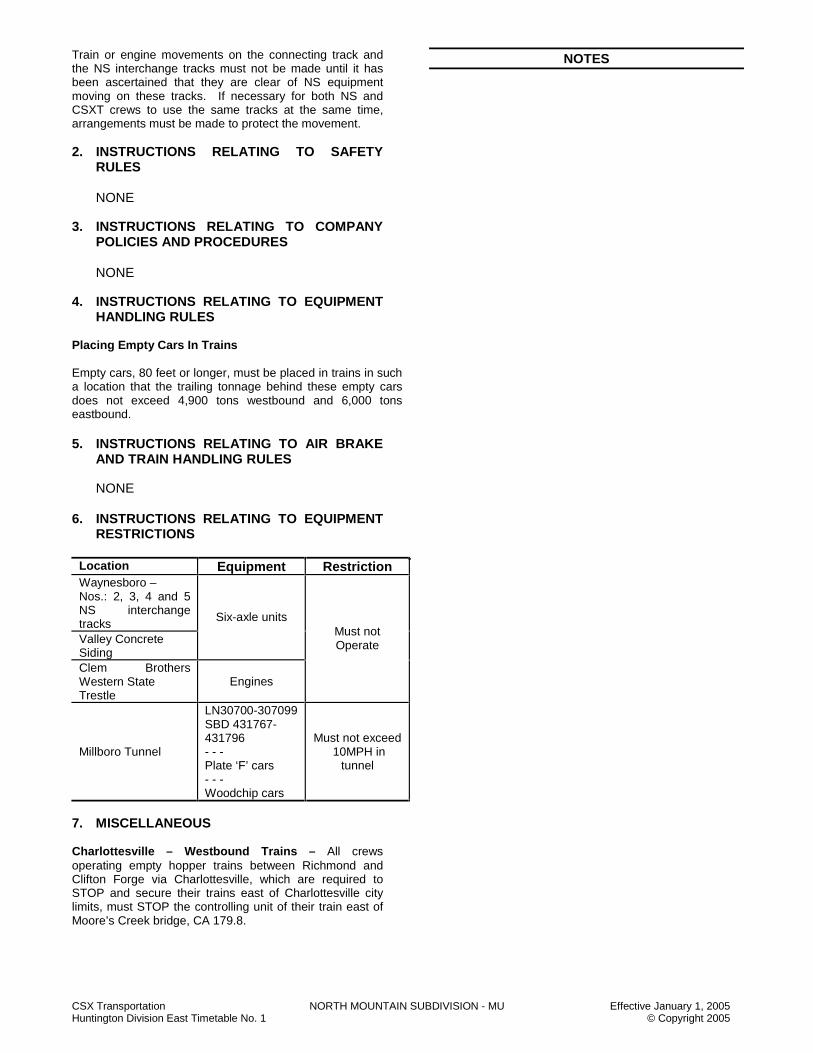
CSX Transportation NORTH MOUNTAIN SUBDIVISION - MU Effective January 1, 2005 Huntington Division East Timetable No. 1 © Copyright 2005
Train or engine movements on the connecting track and the NS interchange tracks must not be made until it has been ascertained that they are clear of NS equipment moving on these tracks. If necessary for both NS and CSXT crews to use the same tracks at the same time, arrangements must be made to protect the movement. 2. INSTRUCTIONS RELATING TO SAFETY
RULES
NONE 3. INSTRUCTIONS RELATING TO COMPANY
POLICIES AND PROCEDURES
NONE 4. INSTRUCTIONS RELATING TO EQUIPMENT
HANDLING RULES Placing Empty Cars In Trains Empty cars, 80 feet or longer, must be placed in trains in such a location that the trailing tonnage behind these empty cars does not exceed 4,900 tons westbound and 6,000 tons eastbound. 5. INSTRUCTIONS RELATING TO AIR BRAKE
AND TRAIN HANDLING RULES NONE 6. INSTRUCTIONS RELATING TO EQUIPMENT
RESTRICTIONS
Location Equipment Restriction Waynesboro – Nos.: 2, 3, 4 and 5 NS interchange tracks Valley Concrete Siding
Six-axle units
Clem Brothers Western State Trestle
Engines
Must not Operate
Millboro Tunnel
LN30700-307099 SBD 431767- 431796 - - - Plate ‘F’ cars - - - Woodchip cars
Must not exceed 10MPH in
tunnel
7. MISCELLANEOUS Charlottesville – Westbound Trains – All crews operating empty hopper trains between Richmond and Clifton Forge via Charlottesville, which are required to STOP and secure their trains east of Charlottesville city limits, must STOP the controlling unit of their train east of Moore’s Creek bridge, CA 179.8.
NOTES

CSX Transportation NORTH MOUNTAIN SUBDIVISION - MU Effective January 1, 2005 Huntington Division East Timetable No. 1 © Copyright 2005
NOTES
NOTES

CSX Transportation NORTHERN SUBDIVISION - NO Effective January 1, 2005 Huntington Division East Timetable No. 1 © Copyright 2005
NORTHERN SUBDIVISION - NO TRACK DIAGRAM AUTHORIZED
SPEED MILE POST STATION
WEST
AUTH FOR
MOVE TWC NOTES
P F CA 530.8 2
ABS-261
45 30 1 3
CA 531.7 RIVERTON
CPS-261
DTC BLOCK SILO
1,2,3
45 30
CA 531.7 RIVERTON
CPS-261 1,2,3
0.7 CA 532.4 GREENUP
45 30 CA 532.8
1 2 ABS-261 DTC BLOCK 70 55 GREEN
79 CA 534.1
CA 535.5 7.0 (1) HBD-DEDAC
CA 539.4 E.E. DG CABIN
CPS-261
0.5 CA 540.2 W.E. DG CABIN DTC BLOCK 1 2 3
ABS-261 EDGE
0.2
CA 541.1 LIMEVILLE
CPS-261
DTC BLOCK 542.0 1.8 ABS-261
LIME 1 2 3
79 55
542.9 NJ CABIN
CPS-261
0.0
50 DTC BLOCK CD NO. 2 SCIOTO
NOR. 1 30 BRIDGE
CJ 1.7 CJ 2.0 TTB
NOR. 2 CD NO. 1 ABS-261
50 4.0
CJ 3.0 MP 3.0
CPS-261
6.3 ABS-261 1 2
CJ 9.3 MINFORD
CPS-261
CJ 9.5 (1) HBD-DEDAC ABS-261 DTC BLOCK 4.7 WHEEL
CJ 14.0 BR CABIN 1 2
CPS-261
8.0 ABS-261 CJ 22.0 TEAYS JCT. DTC BLOCK ROBBIN
50 ABS-261 1,2,3
CR DISP. 94-4
RD 08
CINCINNATI SD
PORTSMOUTH IT
CR DISP. 94-2
RD 08
RUSSELL SD
CR DISP. 94-4
RD 08

CSX Transportation NORTHERN SUBDIVISION - NO Effective January 1, 2005 Huntington Division East Timetable No. 1 © Copyright 2005
NORTHERN SUBDIVISION - NO TRACK DIAGRAM AUTHORIZED
SPEED MILE POST STATION
WEST
AUTH FOR
MOVE TWC NOTES
50 ABS-261
1,2,3
0.7 1 2
DTC BLOCK ROBBIN
CJ 23.0 E.E. ROBBINS
CPS-261 4
CENTER SIDING DTC BLOCK
SSDG ABS-261 HOTEL 1.6 6,600 FT. 4
CJ 24.6 W.E. ROBBINS
CPS-261
50 CJ 27.2 DTC BLOCK 30
ABS-261 GREGGS
50 CJ 28.7
7.3 1 2
CJ 31.3 MR CABIN
CPS--261
CJ 31.6 (2) HBD-DEDAC
ABS-261 9.0
DTC BLOCK ANDY
CJ 40.3 RA JCT.
CPS-261
1 2 4.1
ABS-261
DTC BLOCK MIAMI
CJ 44.4 E.E. VAUCES
CPS-261 4
ABS-261
CENTER SIDING SSDG
5,870 FT. DTC BLOCK 1.4 VAUCES
CJ 45.8 W.E. VAUCES
CPS-261 4
0.5 1 2
ABS-261
CJ 46.3 VA JCT
CPS-261
1.7 ABS-261
DTC BLOCK GILLUM
CJ 48.0 JD CABIN
CPS-261
CJ 51.3 (1) HBD-DEDAC 52.0 ABS-261 DTC BLOCK 53.0 HOPE CJ 54.7 9.3 TTB
CJ 57.3 KN CABIN
CPS-261 4
SSDG
KN SIDING 2.8 14,189 FT.
ABS-261 DTC BLOCK
DELANO
CJ 60.1 ZK CABIN
CPS-261 4
ABS-261
50
DTC BLOCK ZEKE
1,2,3
GM RY
CR DISP. 94-2
RD 08
RENICK IT

CSX Transportation NORTHERN SUBDIVISION - NO Effective January 1, 2005 Huntington Division East Timetable No. 1 © Copyright 2005
NORTHERN SUBDIVISION - NO TRACK DIAGRAM AUTHORIZED
SPEED MILE POST STATION
WEST
AUTH FOR
MOVE TWC NOTES
50 ABS-261
1,2,3
5.0
DTC BLOCK ZEKE
CJ 65.1 LE CABIN
CPS-261
1 2 ABS-261 3.1 DTC BLOCK CJ 68.2 VEE VEE 3.3 1 2 ABS-261
CJ 71.5 HC CABIN
CPS-261
CJ 74.0 (1) HBD-DEDAC ABS-261 DTC BLOCK 83.0 FITE 84.0 13.3
CJ 84.8 LOCKBOURNE
CPS-261
1 2 DTC BLOCK ABS-261 BOURNE 1,2,3 YL 6.8
50 CJ 91.2 CH CABIN CPS-261 NEW YARD LONG LEAD YL HILL TRACK
PARSONS YARD 96
10 YL 1 MASON LEAD
CK 6.6 PA CABIN P04 CPS-261
MASON P03 YARD
10 P01 P02 YL
106.4 MILES RIVERTON TO CH CABIN
STATION PAGE NOTES NOTE 1: Signals aspects displayed are in accordance with Signal Aspect Rules C1281 – C1298. NOTE 2: Between MP CA 531.7 and MP CJ 91.6, trains in excess of 7,000 tons, but not exceeding 14,000 tons will not exceed 40 MPH. NOTE 3: Between MP CA 531.7 and MP CJ 91.6, trains in excess of 14,000 tons will not exceed 35 MPH. NOTE 4: Rule ABS-261 is in effect on KN Siding, Robbins and Vauces Center Sidings.
CR DISP. 94-2
RD 08
ATHENS IT

CSX Transportation NORTHERN SUBDIVISION - NO Effective January 1, 2005 Huntington Division East Timetable No. 1 © Copyright 2005
NORTHERN SUBDIVISION SPECIAL INSTRUCTIONS
1. INSTRUCTIONS RELATING TO OPERATING RULES
Switching 1. Wurtland – Cars must not be kicked from the main
track to the loading track at the Dupont Chemical Plant. All cars handled in this track must be moved by the engine, not exceeding 8 MPH.
Hand Brakes - Cars Location Loaded Empty Comments Northern 5 HB 5 HB -- Renick IT 1 HB 1 HB -- Gregg IT 10% 10% Not less than 2 HB Radio Stations and Instructions Crews at the Dupont Plant, Wurtland, KY may use Channel 70 while switching. 2. INSTRUCTIONS RELATING TO SAFETY
RULES
NONE 3. INSTRUCTIONS RELATING TO COMPANY
POLICIES AND PROCEDURES
NONE 4. INSTRUCTIONS RELATING TO EQUIPMENT
HANDLING RULES Moving Clearance Implicated Shipments Northern SD RJ Cabin to CH Cabin 1) Control – CSX Chief/Dispatcher Jacksonville protects with Hi-Wide message to all crews. 5. INSTRUCTIONS RELATING TO AIR BRAKE
AND TRAIN HANDLING RULES
NONE 6. INSTRUCTIONS RELATING TO EQUIPMENT
RESTRICTIONS Parsons Yard – When loaded, hoppers in DEEX 1001 through DEEX 4143 must use tracks P01 and P02. 7. MISCELLANEOUS 7.1 Emergency Evacuation Procedures E.I. Dupont Corp., VEE, Ohio, MP CJ 68.2 – When an emergency requiring an evacuation occurs, Dupont will sound 10 short blasts on an air horn, twice.
This serves as a warning to everyone within the confines of the plant that an emergency exists and an evacuation will be made. Should an evacuation signal be sounded, CSXT personnel will be governed as follows:
A) Shut down locomotive(s). B) Wait next to the locomotive for a Dupont
emergency response person. C) Upon arrival of the emergency respondent,
follow him/her to a safer location. D) Follow all directions given at that safer location. E) When Dupont feels it is safe for your return, you
will be released. 7.2 Eastbound trains must report the following conditions
to the Coal Hump or Big Four yardmaster at MP CA 533.0, west of Greenup, KY:
A) Condition of locomotives and direction of units. B) Supplies if needed C) HTD D) ETD E) Car count
7.3 Westbound trains must report the following
conditions to the Parsons yardmaster at MP CJ 91.2, CH Cabin:
A) Condition of locomotives and direction of units B) Supplies if needed C) HTD D) ETD E) Car count
7.4 Industrial Tracks A) Athens Industrial Track
1. Athens IT extends between MP CK 6.6 and the IOCR connection at MP CK 9.1
2. Authority For Movement
Between Location/MP
Authority for Movement
Signal Aspect Rules
MP CK 9.1 and Valley Crossing
96
Valley Crossing CPS-261 (193) C1281 – C1298 Valley Crossing and MP CK 6.7 96
PA Cabin MP CK 6.6 and MP CK 6.7
CPS-261 (193) C1281 – C1298
Hill Track 96
3. When the absolute signal, governing movement at Valley Crossing, displays a STOP Aspect, the crew will contact the CR dispatcher for permission to pass the STOP signal, and after observing that the crossing is clear, will be governed as follows:

CSX Transportation NORTHERN SUBDIVISION - NO Effective January 1, 2005 Huntington Division East Timetable No. 1 © Copyright 2005
a) Operate the emergency release button located in the relay case in the southwest quadrant of the crossing until indication light is illuminated.
b) Signal should clear after two (2) minutes. c) The CR dispatcher radio channel is 94 and the
call in number is 2. The CR dispatcher telephone number is 1-800-365-3697.
4. Trains or engines will not exceed 10 MPH between
MP CK 6.6 and MP CK 9.1. Trains or engines will not exceed 10 MPH on the Hill track.
5. Instructions must be obtained from the Parsons
yardmaster before entering or fouling the Athens IT between MP CK 6.6 and MP CK 9.1 and before entering or fouling the Hill track. Trains or engines must report to the Parsons yardmaster when clear of these tracks.
6. Trains or engines must secure yarding instructions
from the Parsons yardmaster before passing MP CK 9.1.
7. Prior to fouling or occupying the track between MP
CK 6.6 and MP CK 9.1, and prior to fouling or occupying the Hill track, Engineering forces will make arrangements with the Parsons yardmaster, who is responsible for directing movements on these tracks. Engineering forces must report to the Parsons yardmaster when clear of these tracks.
Engineering forces working between the signals (OS Circuits) at PA Cabin or Valley Crossing, after making arrangements with the Parsons yardmaster must also secure protection from the CR desk train dispatcher as required by Roadway Worker Rules. Engineering forces working in those areas governed by Rule 96, after making arrangements with the Parsons yardmaster, must protect themselves in accordance with Roadway Worker Rules for protection on non-controlled tracks.
B. Portsmouth Industrial Track - The Portsmouth industrial track is designated as excepted track. C. Renick Industrial Track
1. Trains and engines will not exceed 25 MPH, except as noted below:
Between Location/Milepost MPH BBB 80.0 and BBB 83.2 10 Renick Jct. and BB 98.2 20 Renick Jct. and Scioto Jct. 10
2. Engine speed indicators, odometers and RDU equipment must be checked between MP BB 103.1 and MP BB 104.1.
3. NS Crossing – When a STOP aspect is displayed
by the absolute signal governing movement over the NS crossing and no conflicting movement is apparent, trains or engines will be governed as follows:
The conductor or engineer will secure permission to proceed from the NS control station. After securing permission to proceed, trains will pass the STOP signal, at least 30 feet, but not fouling the crossing. Wait 5 minutes and proceed. The NS control station is the NS dispatcher in Ft. Wayne, Indiana. Use radio Channel 72 and call in No. 5 or telephone number 1-219-493-5455 when contacting the NS dispatcher.
4. Chillicothe – Watt Street Crossing - Flashlight and
gate protection for Watt Street crossing will not operate for eastbound movement from the bids terminal to the main track until engine occupies main track between switch and crossing. Crossing protection may also be operated manually by using switch key control located at crossing.
5. Bids Terminal - During normal switching hours
hazardous material will not be transferred in the terminal. Other than normal switching hours, the facility will be blue flagged. If a switch is required at other than normal switching hours, a Bids terminal supervisor will meet the rail switch crew, remove the blue flags and will verify terminal activity and that all hazardous material transfers are shut down.
The normal switching hours for the Chillicothe Bids terminal are between 1200 and 1500 hours (CSX standard time) daily.
6. Renick IT radio station is at Chillicothe between the
hours of 0600 and 1400 (CSX standard time) Monday through Friday. channels 08 and 28 are monitored. This is a terminal type radio station.
7. Thru-Truss Bridge - Thru-Truss Bridge 101/28 is
located east of Renick Jct. at MP BB 101.3. 8. NS TRAINS - NS trains entering the Renick IT will
operate in accordance with CSX Operating Rule 96 and CSX Operating Rule 46.
NOTES

CSX Transportation NORTHERN SUBDIVISION - NO Effective January 1, 2005 Huntington Division East Timetable No. 1 © Copyright 2005
NOTES
NOTES

CSX Transportation OHIO RIVER SUBDIVISION - OR Effective January 1, 2005 Huntington Division East Timetable No. 1 © Copyright 2005
OHIO RIVER SUBDIVISION - OR TRACK DIAGRAM AUTHORIZED
SPEED MILE POST STATION
WEST
AUTH FOR
MOVE TWC NOTES
10 96 END OF TRACK
BN 2.5 WHEELING 2.1 W & LE
BN 4.6 BENWOOD 7 5.9
10 BN 10.5
1.4
20 96
30 BN 11.9 DTC BLOCK SIGN
MOUNDSVILLE TWC-DTC
BN 15.7 EAST CHESTNUT HILL
16.0 5,490 FT.
DTC BLOCK PERK
16.9 DTC BLOCK SIGN WEST CHESTNUT HILL
17.0
BN 20.6 EAST FOSTER DTC BLOCK 1.9 5,940 FT. LANG BN 22.5 WEST FOSTER
BN 24.0 DTC BLOCK SIGN BN 26.2 (1) HBD – DED
DTC BLOCK RING
BN 27.0 DTC BLOCK SIGN 5.4
BN 27.9 EAST NATRIUM 1.4 7,020 FT. DTC BLOCK BN 29.3 WEST NATRIUM WIND
BN 29.5 DTC BLOCK SIGN 6.7
DTC BLOCK 30 TWC-DTC MOBAY 20
BN 35.8
BN 35.9 DTC BLOCK SIGN
BN 36.0 EEDT HANNIBAL ss
6
#2 RT BN 37.8 WEDT HANNIBAL 2.0 ss BN 38.0 BROOKLYN JCT.
20
96
30
BN 40.4 DTC BLOCK SIGN 4.8 TWC-DTC
6
41.0 42.0 BN 42.8 PADEN CITY
30 DTC BLOCK BN 46.8
JUNK 15
BN 47.3
30 BN 50.0 DTC BLOCK SIGN
TWC-DTC DTC BLOCK
SISTER
CJ DISP. 14-5
RD 08
3.8
WHEELING IT
4.9
9.2
SHORTLINE SD
#1 RT
CSX Transportation OHIO RIVER SUBDIVISION - OR Effective January 1, 2005 Huntington Division East Timetable No. 1 © Copyright 2005
OHIO RIVER SUBDIVISION - OR TRACK DIAGRAM AUTHORIZED
SPEED MILE POST STATION
WEST
AUTH FOR
MOVE TWC NOTES
30 TWC-DTC BN 51.9 FRIENDLY DTC BLOCK 3.6 SISTER BN 54.3 (1) HBD-DED
BN 55.5 DTC BLOCK SIGN BENS RUN
5,940 FT. BN 56.7 WEST BENS RUN ss
30
BN 64.0 DTC BLOCK
10 BN 64.2 SAINT MARY’S BENS
30 BN 64.5
BN 67.0 DTC BLOCK SIGN BN 68.8 EUREKA 11.4 BN 79.2 (1) HBD-DED
DTC BLOCK BELL
BN 80.3 DTC BLOCK SIGN EAST WILLIAMSTOWN
30 15
BN 81.0 3,735 FT.
BN 81.1 WEST WILLIAMSTOWN DTC BLOCK
15 TOWN BN 81.4
84.0 85.0
30
TWC-DTC
BN 90.7 DTC BLOCK SIGN 11.8 96 20
BN 92.9 PARKERSBURG 5 BN 93.3 93.3 6 BN 93.5 TTB BN 94.1 OR JCT. 2.4 LITTLE KANAWHA 4 BN 94.2 94.2
20 96 30
BN 95.3 DTC BLOCK SIGN TWC-DTC BN 99.9 WASHINGTON BN 102.0 (1) HBD-DED 3
DTC BLOCK PARKER
BN 102.1 DTC BLOCK SIGN 12.7
106.0 107.0 DTC BLOCK BN 108.0 EAST HARRIS FERRY ss FERRY 1.1 5,850 FT.
BN 109.1 DTC BLOCK SIGN WEST HARRIS FERRY
30 BN 117.5
117.5 DTC BLOCK 20
11.2 EQHR HYDRO BN 117.8 4453 30
BN 118.0 118.0 TWC-DTC
12.1
1.2
0.9
TRANSFER TRACK TO HIGH YARD
EQHR- 4453

CSX Transportation OHIO RIVER SUBDIVISION - OR Effective January 1, 2005 Huntington Division East Timetable No. 1 © Copyright 2005
OHIO RIVER SUBDIVISION - OR TRACK DIAGRAM AUTHORIZED
SPEED MILE POST STATION
WEST
AUTH FOR
MOVE TWC NOTES
30 TWC-DTC DTC BLOCK HYDRO
BN 120.3 DTC BLOCK SIGN BN 120.6 POLK DTC BLOCK BN 125.0 (1) HBD-DED POLK
BN 127.8 DTC BLOCK SIGN 30 25
BN 128.0 13.4
BN 128.4 RAVENSWOOD DTC BLOCK BN 128.4 TTB RAVEN
25 30
BN 128.7
BN 133.8 DTC BLOCK SIGN EAST SWITCH KAISER
30 7,400 FT. 25
BN 134.5 KAISER 1.5
BN 135.2 WEST SWITCH KAISER ss
DTC BLOCK KAISER
BN 139.8 DTC BLOCK SIGN WEST SWITCH MILLWOOD 4.6
BN 146.2 (1) HBD-DED 147.0 148.0 22.6
DTC BLOCK MILL
BN 149.0 DTC BLOCK SIGN
BN 150.0 GRAHAM
DTC BLOCK LETART
BN 153.0 DTC BLOCK SIGN DTC BLOCK
MASON
BN 162.4 DTC BLOCK SIGN EAST SWITCH LAKIN
8,000 FT BN 164.1 WEST SWITCH LAKIN ss
DTC BLOCK BADEN
BN 169.8 DTC BLOCK SIGN
BN 172.7 POINT PLEASANT BN 173.0 TTB
25 DTC BLOCK 30
BN 175.0 STAFF
BN 176.6 (1) HBD-DED
BN 182.9 DTC BLOCK SIGN EAST SWITCH BEN LOMOND
6,100 FT. DTC BLOCK BN 184.1 WEST SWITCH BEN LOMOND ss CRAB
BN 186.0 DTC BLOCK SIGN 3.5 DTC BLOCK BN 187.6 APPLE GROVE 2,700 FT. ASHTON
BN 189.8 DTC BLOCK SIGN 17.8 BN 201.1 (1) HBD-DED
DTC BLOCK LESAGE
BN 204.4 DTC BLOCK SIGN
BN 205.4 COX LANDING 206.0 5.9 207.0 2
30 TWC-DTC
DTC BLOCK BLUEJAY
BN 211.3 DTC BLOCK SIGN 5th AVENUE 1 10
ABS-261
1.2
1.7
18.8
0.6
NS RR
CSX Transportation OHIO RIVER SUBDIVISION - OR Effective January 1, 2005 Huntington Division East Timetable No. 1 © Copyright 2005
OHIO RIVER SUBDIVISION - OR TRACK DIAGRAM AUTHORIZED
SPEED MILE POST STATION
WEST
AUTH FOR
MOVE TWC NOTES
10 BN 211.9 GUYANDOTTE
CPS-261
P F CA 501.0 GUYANDOTTE
CPS-261
(193)
SHOPS
65 50
211.3 MILES WHEELING TO GUYANDOTTE
STATION PAGE NOTES
NOTE 1: All signals are Signal Rule C1281 – C1298. NOTE 2: To avoid blocking highway crossings, Westward trains must stop at BN 209.9 unless otherwise instructed. NOTE 3: Equipment Handling Rule 4304-A modified at BN 102.0 as follows: Westbound trains receiving an indication other than dragging equipment,
from the defect detector at BN 102.0, are permitted to proceed, not exceeding 5 MPH, as far as BN 104.8. Inspections should be confined, when practical, to an area between BN 103.8 and BN 104.8.
NOTE 4: Do not exceed 10 MPH on the Little Kanawha Railroad Interchange track at Parkersburg. NOTE 5: Do not exceed 20 MPH on the Little Kanawha River Bridge at Parkersburg. NOTE 6: Speeds between BN 90.7 and BN 95.3 and BN 35.8 and BN 40.4 apply to movements on the running track(s) only. NOTE 7: MP BN 11.9 to end of track is designated the Wheeling Industrial track.
AN DISP. 20-3
RD 08 KANAWHA SD

CSX Transportation OHIO RIVER SUBDIVISION - OR Effective January 1, 2005 Huntington Division East Timetable No. 1 © Copyright 2005
OHIO RIVER SUBDIVISION SPECIAL INSTRUCTIONS 1. INSTRUCTIONS RELATING TO OPERATING
RULES Spring Switches
Location Normal Position
Facing Speed
When Springing
Hannibal EEDT No. 1 Track 30 25 Hannibal WEDT No. 2 Track 20 15 WE Bens Run Main Track EE Harris Ferry Main Track
30
WE Kaiser Main Track WE Lakin Main Track
25
WE Ben Lomond Main Track 30
10
Note: Eastbound APP signal for west switch Lakin located at BN 165.7.
Highway Crossings at Grade Providing Highway Crossing Protection Trains will provide protection against vehicular traffic before moving over highway or street crossings designated below: Location Highway Crossing Long Reach Route 2 Hartley Oil Route 68 American Alloy Route 33 Consolidated Aluminum Route 2 Note: 1. Train movements must be flag protected at GE
Plastics main road crossing, when switching GE or running around cars at GE.
2. When necessary to operate the manual control device instrument case, to cause flashers to operate before fouling crossing, it is also required after movement is clear of crossing to operate this device to stop operation of the flashers.
DuPont – All car movements over grade crossings within the plant at DuPont must be preceded by a flagman. The engine bell must be rung when locomotives precede the movement. Benwood/Wheeling – All grade crossings in Benwood/Wheeling, with flashing signals, must be protected with flag protection when signals fail to actuate account of rusty rail conditions. All grade crossings protected with cross bucks in Benwood/Wheeling must be flag protected. Natrium Storage Siding – All trains using Natrium Storage Siding must flag protect the PPG road crossing due to rusty rail conditions. Parkersburg Running Track – Trains or engines must approach crossings prepared to STOP and must not foul crossings unless automatic grade crossing warning devices are operating properly or the crossing is
protected by a crew member on the ground at the crossing. Parkersburg Yard Track – Trains or engines must approach crossings prepared to STOP and must not foul crossings unless automatic grade crossing warning devices are operating properly or the crossing is protected by a crew member on the ground at the crossing. Parkersburg Yard Track #16 – This track has an (island) protection circuit and the train has to be occupying the island at the crossing before the flashers work as the gates come down. Parkersburg – 29th Street – When approaching 29th Street, the crew must operate in a manner that will insure 20 seconds of protection is available before equipment fouls the crossing per Operating Rule 100-E. Switching Parkersburg – High Yard – No more than two (2) car cuts will be cut off in motion or from a static drop. Hand Brakes – Cars
Unattended Hand Brake Application Between Location/Milepost Loads Empties BN 2.5 and BN 211.9 5% 5% Exceptions BN 93.5 and BN 95.3 BN 98.3 and BN 99.0 BN 100.6 and BN 101.8 BN 173.0 and BN 174.1
10% 5%
Receiving Yard at Kaiser 20% 10% Parkersburg High Yard
30% 30% All tracks
Parkersburg All tracks
10% 10% Whenever power is attached
Hand-Operated Switches 1. The normal position of hand-operated switches on
the Parkersburg Running Track and the Marietta SD will be lined for the Marietta SD.
Use of Specified Tracks The following tracks are designated as other than main track and Operating Rule 96 will govern movement. 1. All train movements and OTE movements on the
Wheeling Industrial track between BN 2.5 and BN 11.9 may be made with the verbal instructions of the Brooklyn Junction Yardmaster.
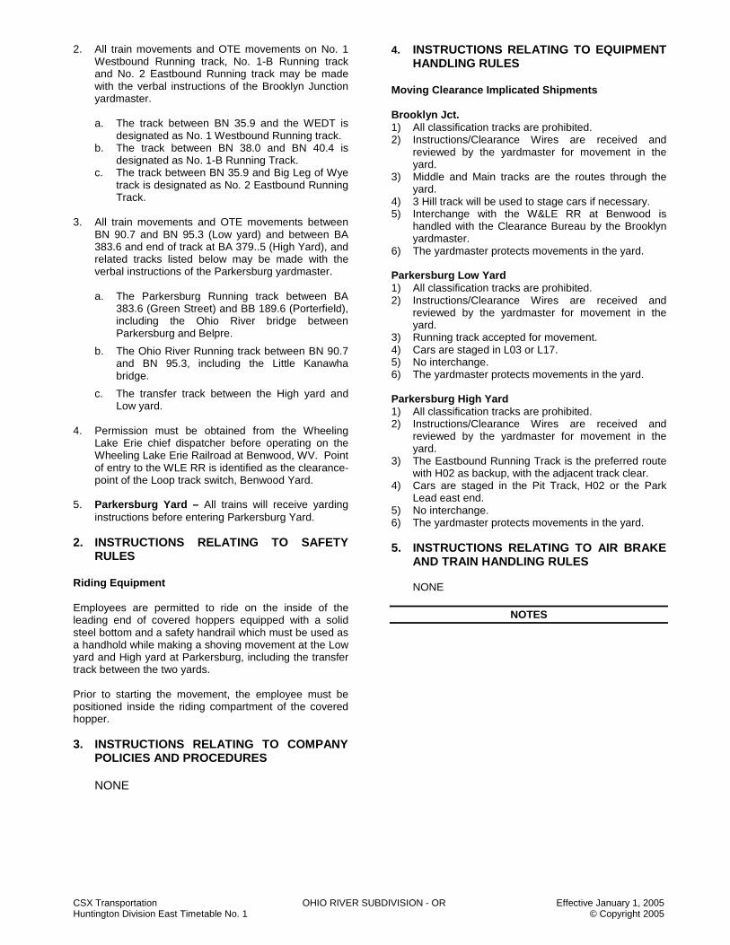
CSX Transportation OHIO RIVER SUBDIVISION - OR Effective January 1, 2005 Huntington Division East Timetable No. 1 © Copyright 2005
2. All train movements and OTE movements on No. 1 Westbound Running track, No. 1-B Running track and No. 2 Eastbound Running track may be made with the verbal instructions of the Brooklyn Junction yardmaster. a. The track between BN 35.9 and the WEDT is
designated as No. 1 Westbound Running track. b. The track between BN 38.0 and BN 40.4 is
designated as No. 1-B Running Track. c. The track between BN 35.9 and Big Leg of Wye
track is designated as No. 2 Eastbound Running Track.
3. All train movements and OTE movements between BN 90.7 and BN 95.3 (Low yard) and between BA 383.6 and end of track at BA 379..5 (High Yard), and related tracks listed below may be made with the verbal instructions of the Parkersburg yardmaster. a. The Parkersburg Running track between BA
383.6 (Green Street) and BB 189.6 (Porterfield), including the Ohio River bridge between Parkersburg and Belpre.
b. The Ohio River Running track between BN 90.7 and BN 95.3, including the Little Kanawha bridge.
c. The transfer track between the High yard and Low yard.
4. Permission must be obtained from the Wheeling
Lake Erie chief dispatcher before operating on the Wheeling Lake Erie Railroad at Benwood, WV. Point of entry to the WLE RR is identified as the clearance-point of the Loop track switch, Benwood Yard.
5. Parkersburg Yard – All trains will receive yarding instructions before entering Parkersburg Yard.
2. INSTRUCTIONS RELATING TO SAFETY
RULES Riding Equipment Employees are permitted to ride on the inside of the leading end of covered hoppers equipped with a solid steel bottom and a safety handrail which must be used as a handhold while making a shoving movement at the Low yard and High yard at Parkersburg, including the transfer track between the two yards. Prior to starting the movement, the employee must be positioned inside the riding compartment of the covered hopper. 3. INSTRUCTIONS RELATING TO COMPANY
POLICIES AND PROCEDURES
NONE
4. INSTRUCTIONS RELATING TO EQUIPMENT HANDLING RULES
Moving Clearance Implicated Shipments Brooklyn Jct. 1) All classification tracks are prohibited. 2) Instructions/Clearance Wires are received and
reviewed by the yardmaster for movement in the yard.
3) Middle and Main tracks are the routes through the yard.
4) 3 Hill track will be used to stage cars if necessary. 5) Interchange with the W&LE RR at Benwood is
handled with the Clearance Bureau by the Brooklyn yardmaster.
6) The yardmaster protects movements in the yard. Parkersburg Low Yard 1) All classification tracks are prohibited. 2) Instructions/Clearance Wires are received and
reviewed by the yardmaster for movement in the yard.
3) Running track accepted for movement. 4) Cars are staged in L03 or L17. 5) No interchange. 6) The yardmaster protects movements in the yard. Parkersburg High Yard 1) All classification tracks are prohibited. 2) Instructions/Clearance Wires are received and
reviewed by the yardmaster for movement in the yard.
3) The Eastbound Running Track is the preferred route with H02 as backup, with the adjacent track clear.
4) Cars are staged in the Pit Track, H02 or the Park Lead east end.
5) No interchange. 6) The yardmaster protects movements in the yard. 5. INSTRUCTIONS RELATING TO AIR BRAKE
AND TRAIN HANDLING RULES
NONE
NOTES
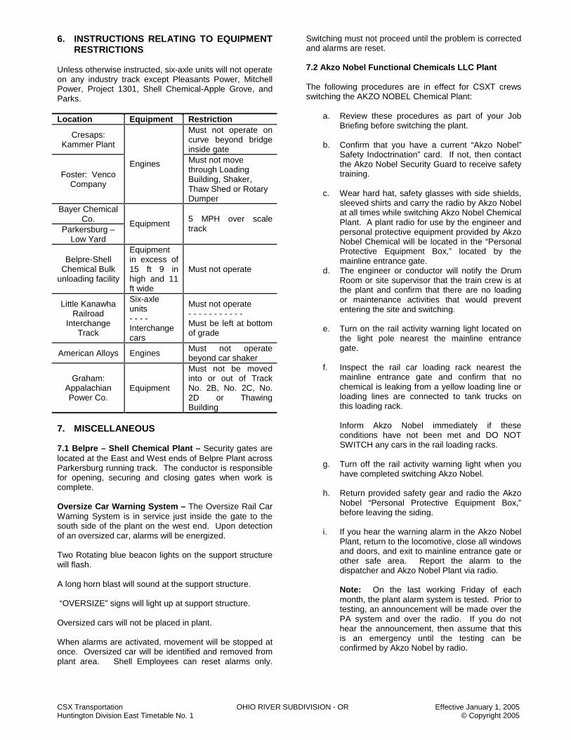
CSX Transportation OHIO RIVER SUBDIVISION - OR Effective January 1, 2005 Huntington Division East Timetable No. 1 © Copyright 2005
6. INSTRUCTIONS RELATING TO EQUIPMENT RESTRICTIONS
Unless otherwise instructed, six-axle units will not operate on any industry track except Pleasants Power, Mitchell Power, Project 1301, Shell Chemical-Apple Grove, and Parks. Location Equipment Restriction
Cresaps: Kammer Plant
Must not operate on curve beyond bridge inside gate
Foster: Venco Company
Engines Must not move through Loading Building, Shaker, Thaw Shed or Rotary Dumper
Bayer Chemical Co.
Parkersburg – Low Yard
Equipment 5 MPH over scale track
Belpre-Shell Chemical Bulk
unloading facility
Equipment in excess of 15 ft 9 in high and 11 ft wide
Must not operate
Little Kanawha Railroad
Interchange Track
Six-axle units - - - - Interchange cars
Must not operate - - - - - - - - - - - Must be left at bottom of grade
American Alloys Engines Must not operate beyond car shaker
Graham: Appalachian Power Co.
Equipment
Must not be moved into or out of Track No. 2B, No. 2C, No. 2D or Thawing Building
7. MISCELLANEOUS 7.1 Belpre – Shell Chemical Plant – Security gates are located at the East and West ends of Belpre Plant across Parkersburg running track. The conductor is responsible for opening, securing and closing gates when work is complete. Oversize Car Warning System – The Oversize Rail Car Warning System is in service just inside the gate to the south side of the plant on the west end. Upon detection of an oversized car, alarms will be energized. Two Rotating blue beacon lights on the support structure will flash. A long horn blast will sound at the support structure. “OVERSIZE” signs will light up at support structure. Oversized cars will not be placed in plant. When alarms are activated, movement will be stopped at once. Oversized car will be identified and removed from plant area. Shell Employees can reset alarms only.
Switching must not proceed until the problem is corrected and alarms are reset. 7.2 Akzo Nobel Functional Chemicals LLC Plant The following procedures are in effect for CSXT crews switching the AKZO NOBEL Chemical Plant:
a. Review these procedures as part of your Job Briefing before switching the plant.
b. Confirm that you have a current “Akzo Nobel”
Safety Indoctrination” card. If not, then contact the Akzo Nobel Security Guard to receive safety training.
c. Wear hard hat, safety glasses with side shields,
sleeved shirts and carry the radio by Akzo Nobel at all times while switching Akzo Nobel Chemical Plant. A plant radio for use by the engineer and personal protective equipment provided by Akzo Nobel Chemical will be located in the “Personal Protective Equipment Box,” located by the mainline entrance gate.
d. The engineer or conductor will notify the Drum Room or site supervisor that the train crew is at the plant and confirm that there are no loading or maintenance activities that would prevent entering the site and switching.
e. Turn on the rail activity warning light located on
the light pole nearest the mainline entrance gate.
f. Inspect the rail car loading rack nearest the
mainline entrance gate and confirm that no chemical is leaking from a yellow loading line or loading lines are connected to tank trucks on this loading rack.
Inform Akzo Nobel immediately if these conditions have not been met and DO NOT SWITCH any cars in the rail loading racks.
g. Turn off the rail activity warning light when you have completed switching Akzo Nobel.
h. Return provided safety gear and radio the Akzo
Nobel “Personal Protective Equipment Box,” before leaving the siding.
i. If you hear the warning alarm in the Akzo Nobel
Plant, return to the locomotive, close all windows and doors, and exit to mainline entrance gate or other safe area. Report the alarm to the dispatcher and Akzo Nobel Plant via radio.
Note: On the last working Friday of each month, the plant alarm system is tested. Prior to testing, an announcement will be made over the PA system and over the radio. If you do not hear the announcement, then assume that this is an emergency until the testing can be confirmed by Akzo Nobel by radio.

CSX Transportation OHIO RIVER SUBDIVISION - OR Effective January 1, 2005 Huntington Division East Timetable No. 1 © Copyright 2005
7.3 Parkersburg Running Track (Ohio River Bridge) Eastbound trains will not pass BB 194.1 (the west approach of the Ohio River bridge at Parkersburg), until they receive yarding instructions from the yardmaster at Parkersburg.
7.4 INDUSTRIAL TRACKS
A) Little Kanawha IT B) Wheeling IT
NOTES
NOTES
CSX Transportation PENINSULA SUBDIVISION - PS Effective January 1, 2005 Huntington Division East Timetable No. 1 © Copyright 2005
PENINSULA SUBDIVISION - PS TRACK DIAGRAM AUTHORIZED
SPEED MILE POST STATION
WEST
AUTH FOR
MOVE TWC NOTES
P F END OF TRACK 96 10 10 CAE 3.2
6.8 NEWPORT NEWS YARD
CAE 10.0 OLD POINT JUNCTION 4.1
10 10 96 79 50 CAE 14.1 CA 14.2
HAMPTON ROADS (HRT) CPS-261
(193)
ABS-261 YL 1 (193)
CA 14.4 FOURTEEN – FIVE
ABS-261
DTC BLOCK 19.0 8.4 NEWS 20.0 ABS-261
CA 22.5 ORIANO
CPS-261
1 2
DTC BLOCK AMOCO
CA 25.4 AMOCO ABS-261 4.7 FT EUSTIS
CA 27.6 LEE HALL
CPS-261 DTC BLOCK
2.0 ABS-261 HALL
CA 29.1 WEST LEE HALL
CPS-261
ABS-261
CA 29.4
CA 30.6 79
CA 31.9 6.1
70 CA 33.2 DTC BLOCK
79 CA 33.1
BUSCH CA 34.5 1 2 ABS-261
CA 35.3 TOPPINGS
CPS-261
2.0 ABS-261 CA 37.3 WILLIAMSBURG STATION DTC BLOCK NORGE CA 38.9 (1) HBD, DED, AC
79 50 ABS-261
HAMPTON IT
AMOCO IT
PENNIMAN IT
AL DISP. 14-1
RD 08 YD-70

CSX Transportation PENINSULA SUBDIVISION - PS Effective January 1, 2005 Huntington Division East Timetable No. 1 © Copyright 2005
PENINSULA SUBDIVISION - PS TRACK DIAGRAM AUTHORIZED
SPEED MILE POST STATION
WEST
AUTH FOR
MOVE TWC NOTES
P F 79 50
CA 42.6
5.6 ABS-261
70
50
DTC BLOCK NORGE
CA 42.9 NORGE DTC BLOCK T/O
40 T/O 40 TOANO CA 43.0
CPS-261
75 50 1 2 ABS-261
CA 43.2
79
75 CA 44.7
79 CA 45.8
6.3
79
CA 46.3
70
79 CA 48.2
ABS-261
79 50 CA 49.1
DTC BLOCK T/O 40
T/O 40
1 2 TOANO 50
CA 49.2
DIANO
CPS-261
DTC BLOCK ABS-261 DIANO 60
CA 49.9
51.0 75
51.2 12.0
52.0 79
CA 52.6 55
CA 53.0
60
60
CA 54.0
79
CA 56.0
70
CA 56.5 ABS-261 DTC BLOCK 79
50 DIANO 79 25 50 25
CA 58.7 EAST PROVIDENCE FORGE
CPS-261
CSDG DTC BLOCK 12,370 FT.
ABS-261 FORGE M
AIN
SID
ING
MAI
N
SID
ING
79 25 50 25
79 50 CA 61.1 WEST PROVIDENCE FORGE
CPS-261

CSX Transportation PENINSULA SUBDIVISION - PS Effective January 1, 2005 Huntington Division East Timetable No. 1 © Copyright 2005
PENINSULA SUBDIVISION - PS TRACK DIAGRAM AUTHORIZED
SPEED MILE POST STATION
WEST
AUTH FOR
MOVE TWC NOTES
P F ABS-261 DTC BLOCK 79 50 CA 63.0 (1) HBD, DED, AC FORGE
CA 65.5
70
79 CA 65.9
70.0 15.0 71.0
79 70
CA 74.4
70 79
CA 74.8 DTC BLOCK
ABS-261 FORGE CA 76.2 BEULAH CPS-261 1 2 ABS-261 2.1
DTC BLOCK FT. LEE
CA 78.0 YL
ABS-261 CA 78.3 FT LEE CPS-261 ABS-261 CA 79.1
79 2.7 65
CA 80.5
ABS-261 CA 80.8
CA 81.0 DARBYTOWN
CPS-261
(193)
1 2 NO. NO. 65 50 1 2 55 30
CA 81.3 0.7 1=W
CA 81.5 EGYPT CPS-261 0.8 JAMES
55 RIVER IT
50 CA 82.3 SCOTT STREET
WEST END
ABS-
251(
193)
ABS-
251(
193)
CA 83.0 ROUNDHOUSE 30
CA 83.1 R CABIN 2 1 2 NO.1 NO.2
CA 83.3 LOUISANNA STREET
CPS-261
(193)
2
CA 83.4 NICHOLSON STREET CPS-261
(193) ABS-261
30 30 1 2 (193) YL
AIRBASE IT
CSX Transportation PENINSULA SUBDIVISION - PS Effective January 1, 2005 Huntington Division East Timetable No. 1 © Copyright 2005
PENINSULA SUBDIVISION - PS TRACK DIAGRAM AUTHORIZED
SPEED MILE POST STATION
WEST
AUTH FOR
MOVE TWC NOTES
P F 30 30 CA 83.9
CA 84.0 CONEY ISLAND
CPS-261
YL 3 1 2 ABS-261
30 30
CA 84.5 RIVANNA JUNCTION
CPS-261
15
15 2
35 35 CA 84.8
1 ABS-261 CPS-261 1
35 35
CA 85.5 AM JUNCTION
YL
35 35 BBRR
TWC-DTC DTC BLOCK SANDCO
82.3 MILES END OF TRACK TO AM JUNCTION
STATION PAGE NOTES
NOTE 1: All Signals are CSX Operating Rules C1281 – C1298. NOTE 2: Rules ABS-261 are in effect on the East Drill Track between R Cabin and Nicholson Street. NOTE 3: Trains and engines are restricted to 10 MPH when operating through the crossover located between CA 83.9 and CA 84.0 at Richmond.
AM DISP. 14-4
RD 08
RIVANNA SD
BELLWOOD SD 2
BELLWOOD SD 2

CSX Transportation PENINSULA SUBDIVISION - PS Effective January 1, 2005 Huntington Division East Timetable No. 1 © Copyright 2005
PENINSULA SUBDIVISION SPECIAL INSTRUCTIONS
1. INSTRUCTIONS RELATING TO OPERATING RULES
Excepted Tracks The following tracks are designated as excepted tracks: 1. Entire James River yard. 2. All tracks at Camp Morrison except the third rail. 3. New Lead Track 4. Coal Bin Tracks 5. Car Shop Tracks 6. Copeland Park Industrial Lead 7. Hampton Industrial Track 8. The Airbase Industrial track, except between CA
78.6 and CA 79.6. Engine Bell Amoco –The bell will be rung at each crossing within the American Oil Refining Company enclosure. Williamsburg – The bell must be rung continuously when approaching grade crossings within the corporate limits (CA 35.3 and CA 39.0), commencing from a point not more than 1,800 or less than 1,200 feet in advance of the crossing. Engine Horn Williamsburg – The engine horn must not be sounded within the city limits (CA 35.3 and CA 39.0) except in emergency. Ditch lights must be displayed when approaching and traversing the crossings within these limits. Fulton Yard – The engine horn and bell must be sounded when using main and yard tracks as a warning to employees. Train Bulletin And Relase Form Amtrak crews arriving Newport News Yard must obtain instructions from the yardmaster before entering the yard at the Fourteen-Five switch. Amtrak crews must not handle switches within the yard until after instructions are received and any instruction concerning communication with other employees has been accomplished. Road Crossings At Grade Norge – Eastbound freight trains receiving an “approach” aspect on Signal No. 460 will STOP before fouling the private crossing just west of Norge Station and call for instructions. CA 79.0 – State Route 636 (Miller Rd.) – Eastbound trains or engines will STOP 1,100 feet west of the crossing when necessary to STOP before reaching the crossing.
Jefferson Ave. – Trains and engines must secure instructions from the yardmaster before blocking the crossing. To prevent blocking crossings, westbound trains and engines will secure instructions from the yardmaster before proceeding over crossing. Hand Brakes The following chart applies to cars and trains left unattended.
Location Loads Empty Newport News Yard – All tracks including private coal facilities
7 HB 3 HB
Fulton Yard: a) Inbound coal trains destined to Newport News will
have ten (10) hand brakes applied to the head end of the train by the inbound crew. In lieu of 10 hand brakes, the inbound crew may set the retainers in the high-pressure position on the fifteen (15) consecutive head cars. If the inbound crew does not have time, under the Hours of Service Law, the outbound crew, prior to performing the helper service brake test, must apply hand brakes or retainers. The hand brakes or retainers must be released immediately before releasing the automatic brake at the completion of the helper service brake test.
b) Trains yarded at Fulton must have hand brakes
applied on the ten (10) head cars to secure the train. If the train is doubled, the doubled cut must have ten (10) hand brakes applied to secure the cars.
Hand-Operated Switches
1. Fulton Yard:
a) East End of Caboose Track – The normal
position of the east end caboose track is for movement on 18 track.
b) West Switch to Caboose track – The normal position of the switch is for movement to the caboose track.
c) Pusher Track – The normal position of the pusher track switch is for movement on E-16 track.
d) Big Switch – Prior to passing over the Big Switch, all trains and engines must STOP and examine the switch to ensure it is latched, the switch points fit properly and the route is lined.

CSX Transportation PENINSULA SUBDIVISION - PS Effective January 1, 2005 Huntington Division East Timetable No. 1 © Copyright 2005
Newport News Yard:
a) Crossover Switches Between Former XA Tower and 39th Street Bridge – Lined for movement on running track.
b) Crossover East-end Backdoor Track to Open Track – Lined for movement through the crossover.
c) Wye Tracks 39th St. – East and west Wye track switches – Lined for movement on the Open track.
d) Hampton Roads Wye – East and west Wye track switches – Lined for movement on T lead.
e) Peninsula Block Switch – Lined for movement on T lead.
f) Drydock Switch – Lined for movement on Old main track.
g) East switch thoroughfare track – Lined for movement to the running track.
h) East End Running Track—Lined for movement on Pier IX lead.
Use Of Specified Tracks 1. Newport News Yard:
(a) On all tracks trains will operate in accordance with
Operating Rule 96, not exceeding 10 MPH.
Exception: Old Main Line track - not exceeding 25 MPH.
(b) Eastward Trains – Eastbound trains will secure
yarding instructions from the yardmaster prior to passing CA 14.5.
(c) Trains and engines must not occupy the following
tracks without instructions of the yardmaster.
1. Thoroughfare track 2. Running track 3. Old main line track
The yardmaster must not allow a conflicting movement after a crew has been issued a specific route to be used unless a job briefing is held between all concerned to ensure that the route of the train is protected.
(d) Amtrak crews departing Newport News Yard must
have in their possession, read and understand a Dispatchers Bulletin containing train messages for the Huntington and Florence Divisions and the necessary Release Form (available at the Amtrak Station) prior to requesting instructions from the yardmaster to depart Amtrak Siding.
(e) Amtrak crews departing Newport News Yard must
obtain instructions from the yardmaster prior to departing Amtrak Siding. Amtrak crews must not handle switches within the yard until after instructions are received and any instruction concerning communication with other employees has been accomplished.
(f) Newport News Dry-dock and Shipbuilding
Interchange Track
Instructions from the yardmaster must be obtained before pulling cars from the interchange track. The yardmaster must notify the conductor of any shipments exceeding the clearance limits or other conditions prior to giving such instructions.
(g) Private Coal Facilities
Engines must not move through dumpers or thaw sheds except in emergency and under the supervision of an industry representative.
Prior to shoving coal to the private terminals, an additional job briefing must be held to ensure that all members of the train crew (including the utility switchman) and the yardmaster on duty have a clear understanding of the moves to be made. Following this job briefing, a member of the train crew must position himself on the side of the car, on the east end of the leading car, to ensure that the route is lined and clear for the movement.
(h) Dominion Terminal Associates
Crews will not proceed east beyond the “DTA CONTROL POINT” without the permission of the DTA tower operator. Derails are located on the east and west ends of DTA loaded tracks and the west end of DTA empty yard. Crews must report clear to the DTA tower operator after leaving DTA and request permission to re-enter.
DTA has painted a yellow tie approximately 4 car lengths east of the power derails located on the west end of No. 1,2,3 and 4 loaded tracks. Cars delivered to DTA on these tracks must be placed east of the yellow tie to allow room for DTA to couple units to the west end of cars and clear the circuit in order to reapply the derail. (See Note.)
(i) Pier IX
A power derail is located approximately 650 feet east of the east end crossover switch running track to the Pier IX lead. A sign approximately 50 feet west of the power derail on the south side of the Pier IX lead indicates, “PIER IX CONTROL POINT.” All crews must contact the Pier IX tower operator, by use of the phone located at the power derail, prior to passing the “PIER IX CONTROL POINT” sign to request permission to proceed east. Once crew has completed work at Pier IX and passes the “PIER IX CONTROL POINT” sign on the westbound move, the crew will report clear to the yardmaster. (See Note.)
Note: When the DTA or Pier IX tower operator is not on duty, instructions to proceed east beyond the Control Point will be given by the yardmaster. After leaving DTA or Pier IX, crews must report clear to the yardmaster and request further instructions to re-enter.
(j) Test and Repair Facility Tracks
Automatic blue flags and derails are located on the C-1 track at a point 440 feet west of the switch

CSX Transportation PENINSULA SUBDIVISION - PS Effective January 1, 2005 Huntington Division East Timetable No. 1 © Copyright 2005
leading from the C-1 track to the west end of Tracks C02 and C03 and 275 feet west of the switch leading from C-1 track leading to the west end of tracks C-6 and C-5.
A manually operated derail and blue flag are located at the east end of C-2 track. Crews must contact the Mechanical Department foreman on duty for the removal of automatic and manual derails or blue flags.
Crews must not operate on C-4, C-5, C-6, C-7 or C-8 tracks unless under the direct supervision of the Mechanical Department foreman on duty.
2. American Oil Company Refinery Tracks
a) The access gate at the main rail entrance is manned
by guards from 0700 to 1700 daily, except Saturday, Sunday and holidays. When guards are on duty, crews will not pass gate without permission of the guard. During the hours when the gate is unattended, a member of the crew will use the speaker at the main gate, identify self and ask permission to enter plant area. An operator on duty at the power station will acknowledge this request and give necessary clearance for the train to enter plant area.
b) All trains must comply with “STOP” or other signs or
instructions which in any way relate to the movement into any track or area. STOP signs are located at the entrance to the combination unit, south of the tetraethyl lead building and entrance to the tank car loading tracks.
c) Trains must not block road crossings for an undue
length of time, but will cut such crossings as may be necessary.
3. Train Movement at Amoco Branch
a) Trains and engines must not occupy the track section between Wolftrap road crossing CPA 5.0 and the end of the track between the hours of 2300 and 0700.
b) Eastbound trains and engines must STOP clear of Wolftrap Road crossing and not pass that point until after 0700 hours.
c) When it is known that the train will not be clear of these limits prior to 2300 hours, the train dispatcher must be contacted for instructions.
4. Yorktown Power Plant Trains destined for Yorktown Power Plant (VEPCO) must stop short of Wolftrap Road crossing. Once the Job Briefing has been completed with the entire crew, including the utility switchman, the following will govern:
(a) Cut the head (68) cars and pull clear of the
Hornsbyville Road crossing. (b) Pull the head 30 cars into Track 5. (c) Pull the remaining 38 cars through Track 9, placing
the overflow into Track 8.
(d) Back light engines through Track 7 to the west end of Track 5 coupling to the 30 cars and shove east into Track 2.
(e) Pull the remaining 32 cars located west of Wolftrap Road into Track 7 with the overflow into Track 6.
(f) The locomotive will exit through Track 5. When pulling empties the following will govern:
a) Pull Track 2 30 cars and double the cars in the New
Yard. b) Shove back and couple to the empty cars in the
Chlorine track. c) Install the ETD and perform the necessary brake
test.
5. Lee Hall – Fort Eustis Government Track a) Trains will use the Pull-in track expecting to find it
occupied by government equipment. b) Trains must STOP and flag across all railroad
highway grade crossings unless crossings are protected by a government flagman.
6. Naval Weapons Station track
a) The access gate to the rail interchange yard is manned by guards from 0730 to 1500 daily, except Saturdays, Sundays and holidays. To prevent delay, the security officer at 887-7103, or the Naval Quarterdeck officer at 887-4545 must be advised of expected arrival time on Saturdays, Sundays and holidays so arrangements can be made to have the gate open. In an emergency, the conductor will call the security officer or quarterdeck officer.
b) Inbound loads will be shoved into interchange yard (barricaded area) by the CSXT crew. Outbound loads will be picked up from the same area.
c) All movements must be made expecting to find track occupied by government equipment. Spacer cars must not be left in the marshalling yard. These cars should be taken to Newport News or Fulton. Tank cars must not be taken into the marshalling yard, but left outside the fenced area.
7. Anheuser-Busch Industrial Lead
a) Crews switching Anheuser-Busch must contact
Anheuser-Busch Security at Bell telephone number 253-3700 prior to crossing Route 60 to secure permission to enter the plant.
b) Crews will properly use the dual locking arrangement and secure the gate after switching is completed.
8. A.H. Robins Company – Fort Lee
Ethanol unloading facilities are located outside the building on Track B. When the “Ethanol being unloaded” sign is displayed, engines or cars must not pass the grade crossing on either track. Fulton Yard
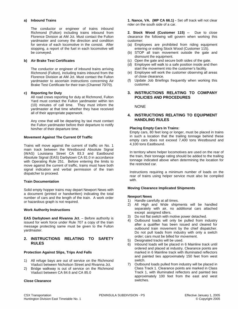
CSX Transportation PENINSULA SUBDIVISION - PS Effective January 1, 2005 Huntington Division East Timetable No. 1 © Copyright 2005
a) Inbound Trains
The conductor or engineer of trains inbound Richmond (Fulton) including trains inbound from Florence Division at AM Jct. Must contact the Fulton yardmaster and convey the direction and condition for service of each locomotive in the consist. After stopping, a report of the fuel in each locomotive will be conveyed.
b) Air Brake Test Certificates
The conductor or engineer of inbound trains arriving Richmond (Fulton), including trains inbound from the Florence Division at AM Jct. Must contact the Fulton yardmaster to ascertain instructions concerning Air Brake Test Certificate for their train (Channel 70/70).
c) Reporting for Duty
All road crews reporting for duty at Richmond, Fulton Yard must contact the Fulton yardmaster within ten (10) minutes of call time. They must inform the yardmaster at that time whether they have received all of their appropriate paperwork. Any crew that will be departing by taxi must contact the Fulton yardmaster before their departure to notify him/her of their departure time.
Movement Against The Current Of Traffic Trains will move against the current of traffic on No. 1 main track between the Westbound Absolute Signal (WAS) Louisiana Street CA 83.3 and Eastbound Absolute Signal (EAS) Darbytown CA 81.0 in accordance with Operating Rule 251. Before entering the limits to move against the current of traffic, trains must have both signal indication and verbal permission of the train dispatcher to proceed. Train Documentation Solid empty hopper trains may depart Newport News with a document (printed or handwritten) indicating the total number of cars and the length of the train. A work order or hazardous graph is not required. Work Authority Instructions EAS Darbytown and Rivanna Jct. – Before authority is issued for work force under Rule 707 a copy of the train message protecting same must be given to the Fulton yardmaster. 2. INSTRUCTIONS RELATING TO SAFETY
RULES Protection Against Slips, Trips And Falls 1) All refuge bays are out of service on the Richmond
Viaduct between Nicholson Street and Rivanna Jct. 2) Bridge walkway is out of service on the Richmond
Viaduct between CA 84.6 and CA 85.0 Close Clearance
1. Nance, VA. (MP CA 66.1) - Set off track will not clear rider on the south side of a car. 2. Stock Wood (Customer 115) -- Due to close clearance the following will govern when working this customer: (a) Employees are prohibited from riding equipment
entering or exiting Stock Wood (Customer 115). (b) STOP all train movement outside the gate and
dismount the equipment. (c) Open the gate and secure both sides of the gate. (d) Employee will walk to a safe position inside and then
start the movement into the customer’s facility. (e) Employee will work the customer observing all areas
of close clearance. (f) Update Job Briefings frequently when working this
customer. 3. INSTRUCTIONS RELATING TO COMPANY
POLICIES AND PROCEDURES
NONE 4. INSTRUCTIONS RELATING TO EQUIPMENT
HANDLING RULES
Placing Empty Cars In Trains: Empty cars, 80 feet long or longer, must be placed in trains in such a location that the trailing tonnage behind these empty cars does not exceed 7,400 tons Westbound and 4,100 tons Eastbound. In territory where helper locomotives are used on the rear of the train, their tonnage rating should be added to the trailing tonnage indicated above when determining the location for the restricted car. Instructions requiring a minimum number of loads on the rear of trains using helper service must also be compiled with.
Moving Clearance Implicated Shipments Newport News 1) Handle carefully at all times. 2) All High and Wide shipments will be handled
separately with air, no additional cars attached except assigned idlers.
3) Do not flat switch with motive power detached. 4) Outbound loads will only be pulled from industry
after a qualifier has been issued and cleared for outbound train movement by the chief dispatcher. Do not pull loads from industry with only a switch order; cars must be billed for movement.
5) Designated tracks will be used. 6) Inbound loads will be placed in 6 Mainline track until
ordered and placed at industry. Clearance points are marked in 6 Mainline track with illuminated reflectors and painted ties approximately 150 feet from west switch.
7) Outbound loads pulled from industry will be placed in Class Track 1. Clearance points are marked in Class Track 1, with illuminated reflectors and painted ties approximately 100 feet from the east and west switches.
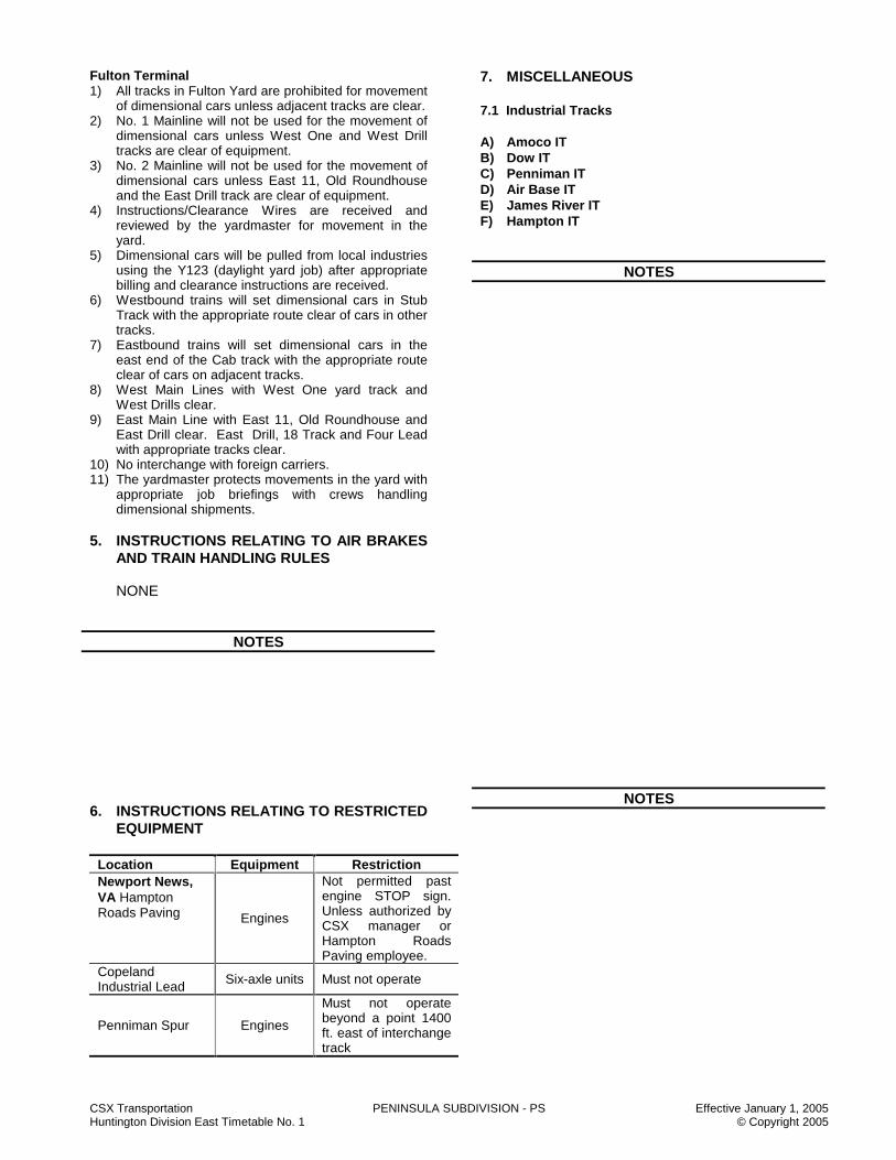
CSX Transportation PENINSULA SUBDIVISION - PS Effective January 1, 2005 Huntington Division East Timetable No. 1 © Copyright 2005
Fulton Terminal 1) All tracks in Fulton Yard are prohibited for movement
of dimensional cars unless adjacent tracks are clear. 2) No. 1 Mainline will not be used for the movement of
dimensional cars unless West One and West Drill tracks are clear of equipment.
3) No. 2 Mainline will not be used for the movement of dimensional cars unless East 11, Old Roundhouse and the East Drill track are clear of equipment.
4) Instructions/Clearance Wires are received and reviewed by the yardmaster for movement in the yard.
5) Dimensional cars will be pulled from local industries using the Y123 (daylight yard job) after appropriate billing and clearance instructions are received.
6) Westbound trains will set dimensional cars in Stub Track with the appropriate route clear of cars in other tracks.
7) Eastbound trains will set dimensional cars in the east end of the Cab track with the appropriate route clear of cars on adjacent tracks.
8) West Main Lines with West One yard track and West Drills clear.
9) East Main Line with East 11, Old Roundhouse and East Drill clear. East Drill, 18 Track and Four Lead with appropriate tracks clear.
10) No interchange with foreign carriers. 11) The yardmaster protects movements in the yard with
appropriate job briefings with crews handling dimensional shipments.
5. INSTRUCTIONS RELATING TO AIR BRAKES
AND TRAIN HANDLING RULES
NONE
NOTES 6. INSTRUCTIONS RELATING TO RESTRICTED
EQUIPMENT
Location Equipment Restriction Newport News, VA Hampton Roads Paving Engines
Not permitted past engine STOP sign. Unless authorized by CSX manager or Hampton Roads Paving employee.
Copeland Industrial Lead Six-axle units Must not operate
Penniman Spur Engines
Must not operate beyond a point 1400 ft. east of interchange track
7. MISCELLANEOUS 7.1 Industrial Tracks A) Amoco IT B) Dow IT C) Penniman IT D) Air Base IT E) James River IT F) Hampton IT
NOTES
NOTES

CSX Transportation PENINSULA SUBDIVISION - PS Effective January 1, 2005 Huntington Division East Timetable No. 1 © Copyright 2005
NOTES

CSX Transportation PICKENS SUBDIVISION - PK Effective January 1, 2005 Huntington Division East Timetable No. 1 © Copyright 2005
PICKENS SUBDIVISION - PK TRACK DIAGRAM AUTHORIZED
SPEED MILE POST STATION
WEST
AUTH FOR
MOVE TWC NOTES
15 BUC 41.9 HAMPTON JCT.
CPS-261 PICK
10 BUH 0.0 DTC BLOCK SIGN
HAMPTON JCT. TWC-DTC
2.2 BUH 2.2 SAGO
BUH 3.0
DTC BLOCK BUH 5.0 SAGO 3.4 BUH 5.6 IC JCT
BUH 5.7 DTC BLOCK SIGN
6.6 BUH 12.2 ALTON DTC BLOCK ALTON
BUH 14.6 DTC BLOCK SIGN
3.6 DTC BLOCK BUH 15.8 ALEXANDER NEWLON 1.2 1,000 FT.
10 BUH 17.0
END OF MAIN TRACK TWC-DTC 17.0 MILES HAMPTON JCT. TO ALEXANDER
CI DISP 14-2
RD 08
COWEN SD
CI DISP 14-2
RD 08
SAW RUN MINE
BM RR
ISLAND CREEK IT

CSX Transportation PICKENS SUBDIVISION - PK Effective January 1, 2005 Huntington Division East Timetable No. 1 © Copyright 2005
PICKENS SUBDIVISION SPECIAL INSTRUCTIONS
1. INSTRUCTIONS RELATING TO OPERATING RULES
Hand Brakes - Locomotives When leaving locomotives unattended at Saw Run mine hand brakes must be applied and tested in an eastbound direction prior to restoring the derail and switch to the normal position. If test in ineffective, locomotives must be left on the main line and blocked or chained if necessary. Hand Brakes - Cars The following chart applies to locomotives, cars and trains left unattended. Between Location/Milepost Loads Empties BUH 0.0 and BUH 3.1 20% 10% BUH 3.1 and BUH 15.3 50% 25% BUH 15.3 and BUH 17.0 20% 10% 2. INSTRUCTIONS RELATING TO SAFETY RULES Exceptions to Making A Safety STOP Employees will make the safety STOP as required by Safety Rule 2201 in all cases except at the locations described below: 1) BUH 2.9
Saw Run Mine when making coupling on loaded coal trains
Crews doubling up loaded trains at the above listed locations must comply with safety rules and SOFA recommendations except for Safety Rule 2201 (safety STOP) and must comply with the following: 1) Safety Rule 2001 - A job briefing must be conducted in
which the movement to be made is discussed. 2) Safety Rule 2201 - Employees must not ride to the
coupling. 3) Safety Rule 2101 - Employees must not mount or
dismount moving equipment. 4) Operating Rule 421 - When radios are used for
communication, crews must give clear and accurate car lengths for the movement to be made.
3. INSTRUCTIONS RELATING TO COMPANY
POLICIES AND PROCEDURES
NONE 4. INSTRUCTIONS RELATING TO EQUIPMENT
HANDLING RULES Placing Empty Cars In Trains Empty, 80 feet and longer cars will be hauled on the rear of the train. Loaded trains handling empty cars will have empty cars, other than 80 feet or longer empty cars, more than 15 cars from head end of the train.
5. INSTRUCTIONS RELATING TO AIR
BRAKE AND TRAIN HANDLING RULES Steep Grade Train Handling Upshur No. 1 Mine - After the brake test is completed the engineer must immediately be notified when the brake pipe pressure on the rear of the train reaches 75 PSI. The train may depart five minutes later. A running release of the train brake will not be made on loaded freight trains between Upshur No. 1 Mine and IC Jct. When a train is stopped between Upshur No. 1 Mine and IC Jct., for any reason, a sufficient number of hand brakes will be applied to hold the train on the grade during the recharging procedure. 6. INSTRUCTIONS RELATING TO EQUIPMENT
RESTRICTIONS Location Equipment Restriction Entire Subdivision
Six-axle Units
Must not operate west of BUH 5.0
Saw Run Mine Equipment
Equipment must not move under loading facilities unless chutes are fully retracted. Equipment must not be placed on tail track without permission of mine personnel.
7. MISCELLANEOUS Conductors Arriving Alexander – Conductors will promptly notify the train dispatcher of their arrival at Alexander. Bell telephones are available. 7.1 Island Creek Industrial Track Movements on the Island Creek Industrial Track are governed by Operating Rule 96.
NOTES

CSX Transportation PIEDMONT SUBDIVISION-P3 Effective January 1, 2005 Huntington Division East Timetable No. 1 © Copyright 2005
PIEDMONT SUBDIVISION - P3 TRACK DIAGRAM AUTHORIZED
SPEED MILE POST STATION
WEST
AUTH FOR
MOVE TWC NOTES
P F YL 1
ABS-261
35 35 CA 85.5 AM JCT. (PENINSULA SD)
CPS-261
YL 25 25 TWC-DTC 1
CA 85.5 DTC BLOCK SIGN AM JCT.
2.3 DTC BLOCK
CA 86.0 SANDCO
CA 87.8 DTC BLOCK
SIGNSANDCO 6.6 CA 93.6 EAST ATLEE
3,130 FT
DTC BLOCK ATLEE
CA 94.4 DTC BLOCK SIGN WEST ATLEE
97.0 8.9 98.0 DTC BLOCK PEAKE
CA 103.3 DTC BLOCK SIGN HANOVER
DTC BLOCK 7.3 BEAR
CA 108.8
CA 110.6 DTC BLOCK SIGN ROUTE 30
1.2 TWC-DTC
CA 111.7
DTC BLOCK
TOMMY
DOSWELL
CPS-261 1
CA 111.9
TWC-DTC
DTC BLOCK BAKER
CA 112.5 DTC BLOCK SIGN WEST DOSWELL
CA 113.6 114.0 6.3
115.0
DTC BLOCK NOEL CA 117.4 EAST NOEL
SDG 3,800 FT
CA 118.1 DTC BLOCK SIGN WEST NOEL
6.2 CA 123.8 EAST BEAVERDAM DTC BLOCK TEMAN
CA 124.3 DTC BLOCK SIGN WEST BEAVERDAM
25 25 ABS-261 DTC BLOCK
VEPCO
AM DISP 14 – 4 RD 08
CQ/AE DISP 20 – 3 RD 96
RF&P SD
AL DISP 14 – 1 RD-08
NO. 2 TRACK BELLWOOD SD FLORENCE DIV
CQ/AE DISP 94 - 7 RD 32
PENINSULA SD

CSX Transportation PIEDMONT SUBDIVISION-P3 Effective January 1, 2005 Huntington Division East Timetable No. 1 © Copyright 2005
PIEDMONT SUBDIVISION - P3 TRACK DIAGRAM AUTHORIZED
SPEED MILE POST STATION
WEST
AUTH FOR
MOVE TWC NOTES
P F TWC-DTC 25 25 16.5 DTC BLOCK VEPCO
CA 140.8 DTC BLOCK SIGN MINERAL
5.6 CA 145.7 EAST LOUISA DTC BLOCK LOUISA
3,260 FT.
CA 146.4 DTC BLOCK SIGN WEST LOUISA
DTC BLOCK 12.9 MELTON TWC-DTC CA 159.3 MP 159 CPS-261 1
25 25
CA 159.9
1.0 ABS-261 20 20
DTC BLOCK 10 10
CA 160.3 EAST GORDONSVILLE
CPS-261 GARY
0.3 ABS-261
10 10 CA 160.6 G TOWER CPS-261 1
20 20 CA 160.6 G TOWER
CPS-261 DTC BLOCK GORDON 1
ABS-261 75.1 MILES AM JUNCTION TO G TOWER
STATION PAGE NOTES
NOTE 1: All Color Light Signals are CSX Operating Rules C1281 – C1298.
AM DISP 14 – 4 RD 08
NORTH ANNA IT
WASHINGTON SD
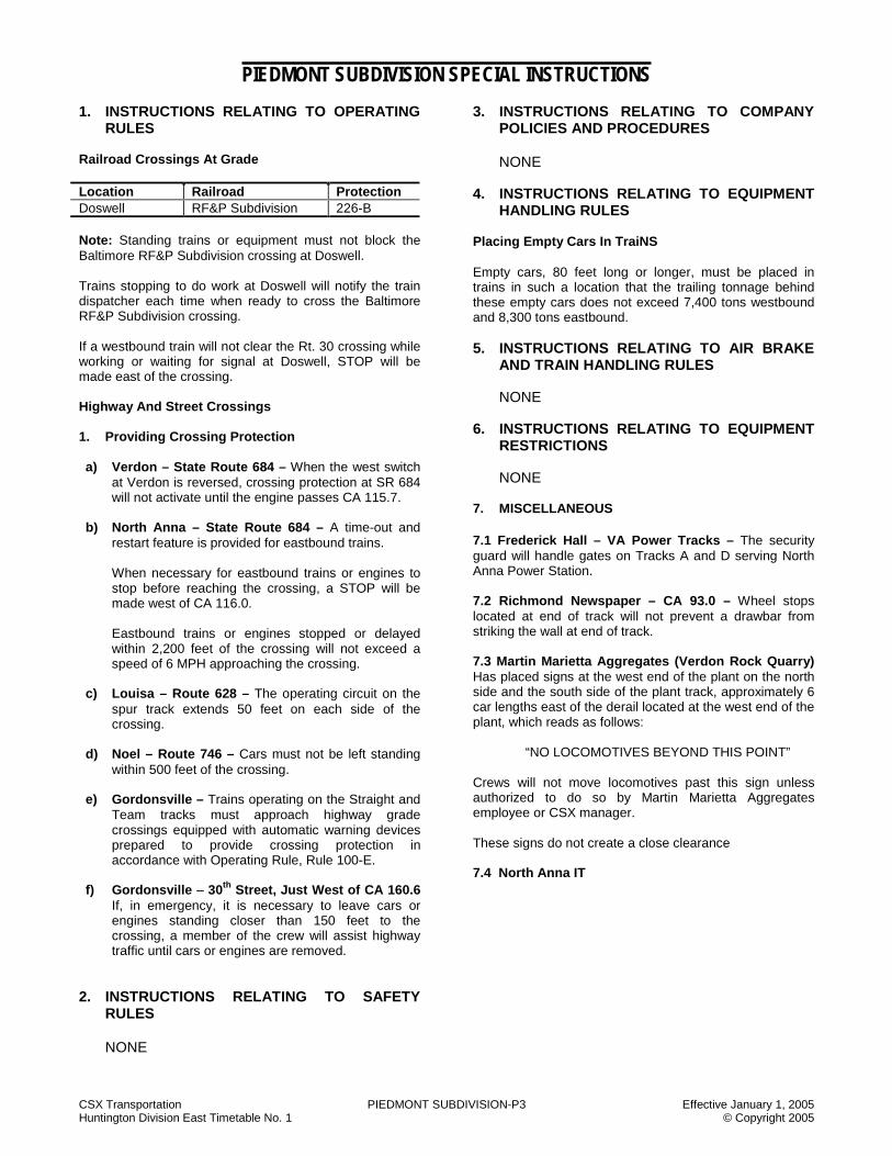
CSX Transportation PIEDMONT SUBDIVISION-P3 Effective January 1, 2005 Huntington Division East Timetable No. 1 © Copyright 2005
PIEDMONT SUBDIVISION SPECIAL INSTRUCTIONS 1. INSTRUCTIONS RELATING TO OPERATING
RULES Railroad Crossings At Grade Location Railroad Protection Doswell RF&P Subdivision 226-B Note: Standing trains or equipment must not block the Baltimore RF&P Subdivision crossing at Doswell. Trains stopping to do work at Doswell will notify the train dispatcher each time when ready to cross the Baltimore RF&P Subdivision crossing. If a westbound train will not clear the Rt. 30 crossing while working or waiting for signal at Doswell, STOP will be made east of the crossing. Highway And Street Crossings 1. Providing Crossing Protection a) Verdon – State Route 684 – When the west switch
at Verdon is reversed, crossing protection at SR 684 will not activate until the engine passes CA 115.7.
b) North Anna – State Route 684 – A time-out and
restart feature is provided for eastbound trains.
When necessary for eastbound trains or engines to stop before reaching the crossing, a STOP will be made west of CA 116.0.
Eastbound trains or engines stopped or delayed within 2,200 feet of the crossing will not exceed a speed of 6 MPH approaching the crossing.
c) Louisa – Route 628 – The operating circuit on the spur track extends 50 feet on each side of the crossing.
d) Noel – Route 746 – Cars must not be left standing
within 500 feet of the crossing. e) Gordonsville – Trains operating on the Straight and
Team tracks must approach highway grade crossings equipped with automatic warning devices prepared to provide crossing protection in accordance with Operating Rule, Rule 100-E.
f) Gordonsville – 30th Street, Just West of CA 160.6
If, in emergency, it is necessary to leave cars or engines standing closer than 150 feet to the crossing, a member of the crew will assist highway traffic until cars or engines are removed.
2. INSTRUCTIONS RELATING TO SAFETY RULES
NONE
3. INSTRUCTIONS RELATING TO COMPANY POLICIES AND PROCEDURES
NONE
4. INSTRUCTIONS RELATING TO EQUIPMENT
HANDLING RULES Placing Empty Cars In TraiNS Empty cars, 80 feet long or longer, must be placed in trains in such a location that the trailing tonnage behind these empty cars does not exceed 7,400 tons westbound and 8,300 tons eastbound. 5. INSTRUCTIONS RELATING TO AIR BRAKE
AND TRAIN HANDLING RULES NONE 6. INSTRUCTIONS RELATING TO EQUIPMENT
RESTRICTIONS
NONE 7. MISCELLANEOUS 7.1 Frederick Hall – VA Power Tracks – The security guard will handle gates on Tracks A and D serving North Anna Power Station. 7.2 Richmond Newspaper – CA 93.0 – Wheel stops located at end of track will not prevent a drawbar from striking the wall at end of track. 7.3 Martin Marietta Aggregates (Verdon Rock Quarry) Has placed signs at the west end of the plant on the north side and the south side of the plant track, approximately 6 car lengths east of the derail located at the west end of the plant, which reads as follows: “NO LOCOMOTIVES BEYOND THIS POINT” Crews will not move locomotives past this sign unless authorized to do so by Martin Marietta Aggregates employee or CSX manager. These signs do not create a close clearance 7.4 North Anna IT

CSX Transportation PIEDMONT SUBDIVISION – P3 Effective January 1, 2005 Huntington Division East Timetable No. 1 © Copyright 2005
NOTES
NOTES

CSX Transportation PINE CREEK SUBDIVISION – P7 Effective January 1, 2005 Huntington Division East Timetable No. 1 © Copyright 2005
PINE CREEK SUBDIVISION - P7 TRACK DIAGRAM AUTHORIZED
SPEED MILE POST STATION
WEST
AUTH FOR
MOVE TWC NOTES
10 CMF 6.0 HOBET NO. 7 END OF TRACK TWC-DTC DTC BLOCK PINE
1.9 CMF 5.3 I.C. MINE NO. 22 3.6
10 CMF 0.0 OMAR TWC-DTC
DTC BLOCK PINE
25 CME 8.1 OMAR
TWC-DTC DTC BLOCK OMAR
6.0 MILES HOBET NO. 7 TO OMAR
BJ DISP 14-4
RD 08
LOGAN & SOUTHERN SD BJ DISP
14-4 RD 08

CSX Transportation PINE CREEK SUBDIVISION – P7 Effective January 1, 2005 Huntington Division East Timetable No. 1 © Copyright 2005
PINE CREEK SUBDIVISION SPECIAL INSTRUCTIONS
1. INSTRUCTIONS RELATING TO OPERATING RULES
Excepted Tracks The entire SD is designated as excepted track. Hand-Operated Switches A. West and east switches at Holden Mine (IC22) will
be left in position last used. Trains or engines must approach these switches expecting to find them lined against their movement.
B. Junction switch, MP CME 8.1, Omar, will be left in
the position last used. Trains and engines must approach this switch expecting it to be lined against their movement.
2. INSTRUCTIONS RELATING TO SAFETY RULES
NONE
3. INSTRUCTIONS RELATING TO COMPANY
POLICIES AND PROCEDURES NONE
4. INSTRUCTIONS RELATING TO EQUIPMENT HANDLING RULES
NONE
5. INSTRUCTIONS REALTING TO AIR BRAKE
AND TRAIN HANDLING RULES
NONE 6. INSTRUCTIONS RELATING TO EQUIPMENT
RESTRICTIONS
NONE 7 MISCELLANEOUS
NONE
NOTES
NOTES

CSX Transportation PINEY CREEK SUBDIVISION - PC Effective January 1, 2005 Huntington Division East Timetable No. 1 © Copyright 2005
PINEY CREEK SUBDIVISION - PC TRACK DIAGRAM AUTHORIZED
SPEED MILE POST STATION
WEST
AUTH FOR
MOVE TWC NOTES
ABS-261
P F
40 35 CA 380.0 PRINCE CPS-261 DTC BLOCK
PRINCE 1
193 14 CAN 0.0 PRINCE
YL
CAN 0.4 TTB 1,2
0.8 CAN 0.8 TERRY SIDING 5,063 FT
193 YL
CAN 1.7 DTC BLOCK SIGN TWC-DTC 2.0 DTC BLOCK 3.0 CURTIS
CAN 4.5 DTC BLOCK SIGN 9.4 CAN 10.2 RODES TWC-DTC
DTC BLOCK RODES
CAN 12.2 DTC BLOCK SIGN 193
3.2 CAN 13.4 RALEIGH 193
CAN 14.3 DTC BLOCK SIGN TWC-DTC 2.7 CAN 16.1 BECKLEY JCT DTC BLOCK 0.3 STARR CAN 16.4 MABSCOTT
CAN 16.5 DTC BLOCK SIGN 2.7 CAN 19.1 BURKS
3,137 FT DTC BLOCK ECCLES 3.0 CAN 22.1 ECCLES JCT 1.5
CAN 23.6 DTC BLOCK SIGN BAYLOR
2.4
14 CAN 26.6 GLEN DANIELS JCT
TWC-DTC
DTC BLOCK BAYLOR
26.6 MILES PRINCE TO GLEN DANIELS JCT.
STATION PAGE NOTES NOTE 1: Signals displayed are in accordance with Signal Aspect Rules C1281-C1298. NOTE 2: Rule ABS-261 is in effect for eastward trains between MP CAN 0.4 and MP CAN 0.0 at Prince.
AM DISP 14-8
RD 08 NEW RIVER SD
NS RR
RALEIGH S-WESTERN &
WINDING GULF SD
MAPLE MEADOW
IT END OF MAIN
TRACK
BJ DISP 14-5
RD 08

CSX Transportation PINEY CREEK SUBDIVISION - PC Effective January 1, 2005 Huntington Division East Timetable No. 1 © Copyright 2005
PINEY CREEK SUBDIVISION SPECIAL INSTRUCTIONS 1. INSTRUCTIONS RELATING TO OPERATING
RULES Hand-Operated Switches Trains departing to Quinnimont from Raleigh - will leave switches and derails as last lined at the east end of Raleigh Yard. 2. INSTRUCTIONS RELATING TO SAFETY
RULES NONE 3. INSTRUCTIONS RELATING TO COMPANY
POLICIES AND PROCEDURES
NONE 4. INSTRUCTIONS RELATING TO EQUIPMENT
HANDLING RULES
NONE 5. INSTRUCTIONS RELATING TO AIR BRAKE
AND TRAIN HANDLING RULES Train Handling Instructions Piney Creek SD Eastbound Trains Between Raleigh and Prince: A) The maximum number of cars which may be handled
without using retainers is 125.
The use of retainers will not be required if the lead locomotive in a consist is equipped with an operative pressure maintaining feature and a minimum of 8 axles of dynamic brake for trains up to 75 cars and 12 axles of dynamic brake for trains over 75 cars. Minimum required rear car brake pipe pressure within 15 PSI of regulating valve setting on lead locomotive. Train must charge an additional 10 minutes after this PSI gradient has been established. One running release is to be made if the total brake pipe reduction has not exceeded 15 PSI before release is to be made and speed is less than 10 MPH. The engineer will use extreme caution when making the running release as speed can get out of control in a very short time. When reapplying train brakes after making a running release the application must be at least 3 PSI greater than the previous reduction in order to prevent an undesired release of train brakes. If the total reduction exceeds 20 PSI at any point between CAN 13.0 and CAN 2.0, the train must be stopped and sufficient hand brakes applied before further descent of the grade.
B) In addition to the requirements of Item A, the
dynamic brake must be tested prior to descending the grade between Raleigh and Prince.
Running dynamic brake test procedures:
2-unit consist: With the locomotive consist moving, go to dynamic braking and determine that the lead locomotive is operative and develops a retarding effect. After determining the lead locomotive is operative, isolate the lead unit and apply the dynamic brake. 3-unit (or more) unit consist: With the locomotive consist moving, go to dynamic braking and determine that the lead locomotive is operative and producing a retarding effect. After determining the lead locomotive is operative, isolate the lead unit and the third unit and use the same procedure to determine the second unit develops a retarding effect. If the axle count dictates a third unit is needed, the second unit must be isolated and it must be determined that the third unit develops a retarding effect. During this verification, employees may position themselves on the appropriate unit to observe it’s retarding effect and communicate results to the entire crew. If additional units are required, the same process will be used to test each additional unit. Tractive Effort – Back Up Movement East End Raleigh Yard – A maximum of 20 power axles may be used when making back up movements with more than 50 cars. Loaded coal trains may be pushed with not more than 20 powered axles at the rear of the train. 6. INSTRUCTIONS RELATING TO EQUIPMENT
RESTRICTIONS
NONE 7. MISCELLANEOUS 7.1 Maple Meadow Industrial Track
Providing Highway Crossing Protection Maple Meadow Mine Extension: All trains must STOP and flag all road crossings between CAV 0.0 to CAV 4.5.
NOTES

CSX Transportation POMEROY SUBDIVISION - PV Effective January 1, 2005 Huntington Division East Timetable No. 1 © Copyright 2005
POMEROY SUBDIVISION - PV TRACK DIAGRAM AUTHORIZED
SPEED MILE POST STATION
WEST
AUTH FOR
MOVE TWC NOTES
20 BBE 127.9 HOBSON 193 1,2 2.8
YL
BBE 125.1 CHESHIRE
EQHR 4453
BBE 119.1 KANAUGA 2,908 FT 0.1
20 BBE 119.0 KANAUGA JUNCTION 193 YL 2
8.9 MILES HOBSON TO KANAUGA JUNCTION
STATION PAGE NOTES NOTE 1: Verbal Permission for Norfolk Southern trains and engines to operate on the Pomeroy SD between Kanauga Jct. and Hobson will be given by
the CSX Train Dispatcher, Jacksonville, through the NS train dispatcher. Before occupying the Pomeroy SD each NS train must receive a CSXT Train Dispatcher Bulletin and Release Form at their on duty location. If their Train Dispatcher Bulletin or Release Form is not available when reporting for duty, the conductor or engineer must promptly contact the CSX train dispatcher. These Dispatcher Bulletins will be furnished to NS trains via electronic fax at either Hobson or Dickinson Yards by the CSX train dispatcher Jacksonville.
Westbound NS trains will report to the NS dispatcher as soon as they clear the Pomeroy SD. The NS dispatcher will then relay the information to the CSX train dispatcher.
Eastbound NS trains will report to the NS dispatcher as soon as they clear the Pomeroy SD after passing Hobson. The NS dispatcher will then relay the information to the CSX train dispatcher.
NOTE 2: The CSX Train dispatcher at Jacksonville will control movements on main track between Hobson and Kanauga Jct. The CSX Train
dispatcher must not permit any opposing movements between Hobson and Kanauga. All trains or engines must report clear after using track section between Hobson and Kanauga Jct.
CJ DISP 14-5
RD 08
NS RR
6.0
NS RR
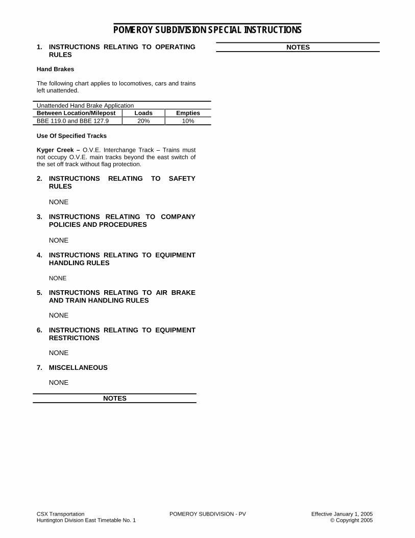
CSX Transportation POMEROY SUBDIVISION - PV Effective January 1, 2005 Huntington Division East Timetable No. 1 © Copyright 2005
POMEROY SUBDIVISION SPECIAL INSTRUCTIONS 1. INSTRUCTIONS RELATING TO OPERATING
RULES Hand Brakes The following chart applies to locomotives, cars and trains left unattended. Unattended Hand Brake Application Between Location/Milepost Loads Empties BBE 119.0 and BBE 127.9 20% 10% Use Of Specified Tracks Kyger Creek – O.V.E. Interchange Track – Trains must not occupy O.V.E. main tracks beyond the east switch of the set off track without flag protection. 2. INSTRUCTIONS RELATING TO SAFETY
RULES
NONE 3. INSTRUCTIONS RELATING TO COMPANY
POLICIES AND PROCEDURES
NONE 4. INSTRUCTIONS RELATING TO EQUIPMENT
HANDLING RULES NONE 5. INSTRUCTIONS RELATING TO AIR BRAKE
AND TRAIN HANDLING RULES
NONE 6. INSTRUCTIONS RELATING TO EQUIPMENT
RESTRICTIONS NONE 7. MISCELLANEOUS NONE
NOTES
NOTES

CSX Transportation POND FORK SUBDIVISION - PF Effective January 1, 2005 Huntington Division East Timetable No. 1 © Copyright 2005
POND FORK SUBDIVISION - PF TRACK DIAGRAM AUTHORIZED
SPEED MILE POST STATION
WEST
AUTH FOR
MOVE TWC NOTES
END OF TRACK 193 CLI 29.1 HARRIS YL
4.2 CLI 24.9 ROCK LICK 193 YL
20 CLI 24.0 DTC BLOCK SIGN TWC-DTC
1.6 CLI 23.3 JASPER
DTC BLOCK LICK
CLI 22.5 DTC BLOCK SIGN
1.6 CLI 21.7 CLINTON 3,240 FT
1.4 DTC BLOCK CLI 20.3 BARRETT ss MIKE ss
CLI 15.7 DTC BLOCK SIGN DTC BLOCK 9,208 FT FLAT
CLI 14.2 DTC BLOCK SIGN 6.2 CLI 14.1 KOHLSAAT ss DTC BLOCK KOHL
CLI 11.7 DTC BLOCK SIGN 2.5 CLI 11.6 WEST JCT. ss
DTC BLOCK 20 JACK
CLI 8.6 10 CLI 8.2 20
CLI 7.9 DTC BLOCK SIGN 7,305 FT
DTC BLOCK LANTA
CLI 6.5 DTC BLOCK SIGN
5.2 CLI 6.4 LANTA
20 TWC-DTC
DTC BLOCK POND
BARRETT IT
WEST FORK SD
BJ DISP 14-2
RD 08

CSX Transportation POND FORK SUBDIVISION - PF Effective January 1, 2005 Huntington Division East Timetable No. 1 © Copyright 2005
POND FORK SUBDIVISION - PF TRACK DIAGRAM AUTHORIZED
SPEED MILE POST STATION
WEST
AUTH FOR
MOVE TWC NOTES
CLI 6.4 DTC BLOCK SIGN LANTA
TWC-DTC DTC BLOCK POND 20
CLI 5.9
0.7
10 ROBINSON CREEK JCT CLI 5.7 20
5.7
20 CLI 0.0 DTC BLOCK SIGN
POND JCT TWC-DTC DTC BLOCK
POND CLF 37.3 POND JCT.
193 YL 1,2,3
29.1 MILES HARRIS TO POND JCT.
STATION PAGE NOTES NOTE 1: Spring Switch Location Normal Position Facing Speed When Springing Pond Jct. – Junction Switch of Pond Fork Subdivision Pond Fork Subdivision 20 MPH 10 MPH
NOTE 2: Trains will call the Danville yardmaster (when on duty) for instructions before passing Pond Jct. MP CLF 37.3. NOTE 3: Providing highway crossing protection Pond Jct. State Route 17:
Westbound approach circuit begins at a point 341 feet east of the Spring Switch at Pond Jct. and is identified by a sign reading, “beginning flasher circuit.” Westbound trains stopping for yarding instructions at Danville must STOP east of this sign. When necessary to meet eastbound trains at Pond Jct., westbound trains on Pond Fork or Coal River Subdivision must not move west of this sign until the rear of eastbound train has cleared westbound approach circuit.
BJ DISP 14-2
RD 08
ROBINSON CREEK IT
COAL RIVER SD BJ DISP 14-2
RD 08
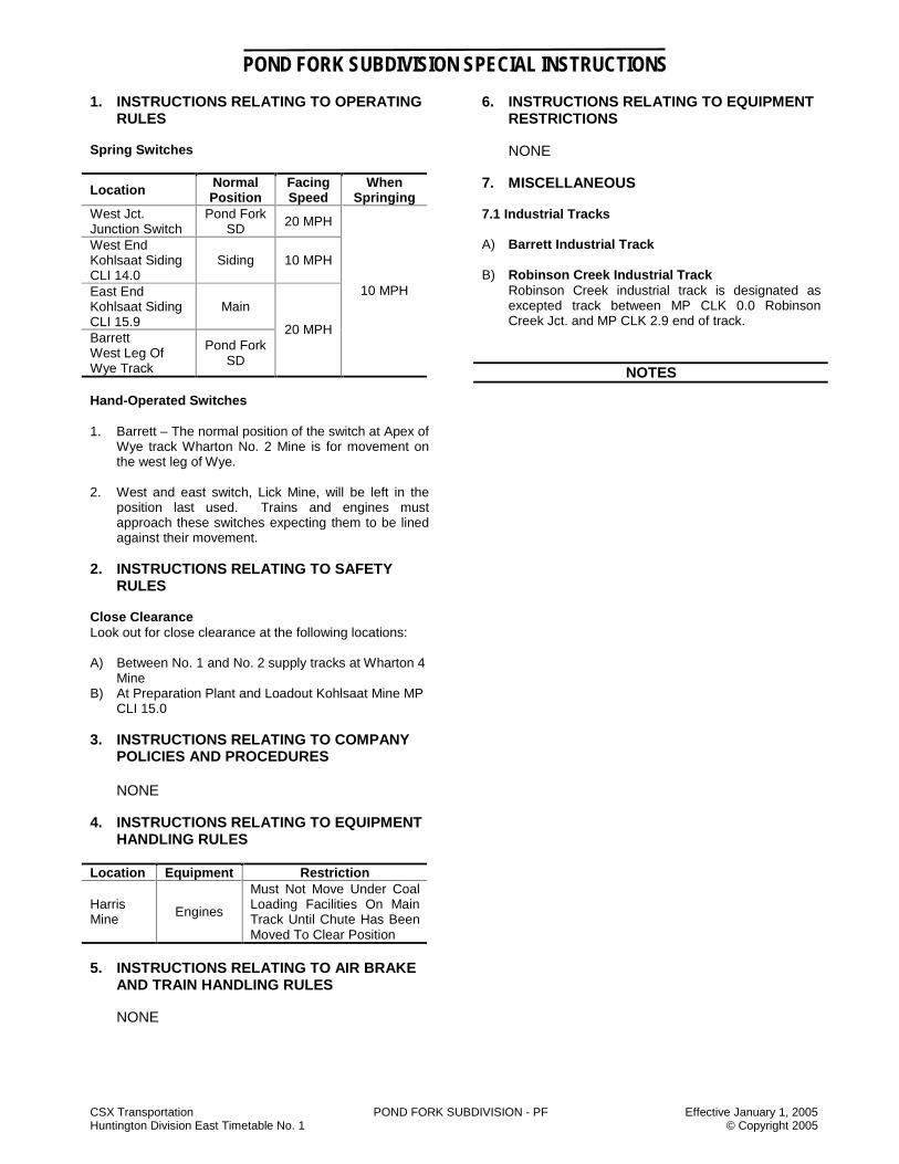
CSX Transportation POND FORK SUBDIVISION - PF Effective January 1, 2005 Huntington Division East Timetable No. 1 © Copyright 2005
POND FORK SUBDIVISION SPECIAL INSTRUCTIONS 1. INSTRUCTIONS RELATING TO OPERATING
RULES Spring Switches
Location Normal Position
Facing Speed
When Springing
West Jct. Junction Switch
Pond Fork SD 20 MPH
West End Kohlsaat Siding CLI 14.0
Siding 10 MPH
East End Kohlsaat Siding CLI 15.9
Main
Barrett West Leg Of Wye Track
Pond Fork SD
20 MPH
10 MPH
Hand-Operated Switches 1. Barrett – The normal position of the switch at Apex of
Wye track Wharton No. 2 Mine is for movement on the west leg of Wye.
2. West and east switch, Lick Mine, will be left in the
position last used. Trains and engines must approach these switches expecting them to be lined against their movement.
2. INSTRUCTIONS RELATING TO SAFETY
RULES Close Clearance Look out for close clearance at the following locations: A) Between No. 1 and No. 2 supply tracks at Wharton 4
Mine B) At Preparation Plant and Loadout Kohlsaat Mine MP
CLI 15.0 3. INSTRUCTIONS RELATING TO COMPANY
POLICIES AND PROCEDURES
NONE 4. INSTRUCTIONS RELATING TO EQUIPMENT
HANDLING RULES Location Equipment Restriction
Harris Mine Engines
Must Not Move Under Coal Loading Facilities On Main Track Until Chute Has Been Moved To Clear Position
5. INSTRUCTIONS RELATING TO AIR BRAKE
AND TRAIN HANDLING RULES
NONE
6. INSTRUCTIONS RELATING TO EQUIPMENT RESTRICTIONS
NONE
7. MISCELLANEOUS 7.1 Industrial Tracks A) Barrett Industrial Track B) Robinson Creek Industrial Track Robinson Creek industrial track is designated as
excepted track between MP CLK 0.0 Robinson Creek Jct. and MP CLK 2.9 end of track.
NOTES

CSX Transportation POND FORK SUBDIVISION - PF Effective January 1, 2005 Huntington Division East Timetable No. 1 © Copyright 2005
NOTES
NOTES
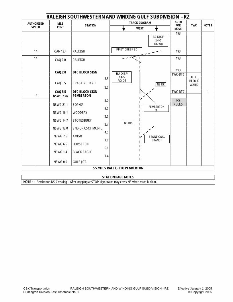
CSX Transportation RALEIGH SOUTHWESTERN AND WINDING GULF SUBDIVISION - RZ Effective January 1, 2005 Huntington Division East Timetable No. 1 © Copyright 2005
RALEIGH SOUTHWESTERN AND WINDING GULF SUBDIVISION - RZ TRACK DIAGRAM AUTHORIZED
SPEED MILE POST STATION
WEST
AUTH FOR
MOVE TWC NOTES
193
14 CAN 13.4 RALEIGH 193
193 14 CAQ 0.0 RALEIGH
193
CAQ 2.0 DTC BLOCK SIGN TWC-DTC 3.5 CAQ 3.5 CRAB ORCHARD 2.0
CAQ 5.5 TWC-DTC
DTC BLOCK WARD
1
14 NSWG 23.6 DTC BLOCK SIGN PEMBERTON
2.5 NSWG 21.1 SOPHIA
NS RULES
5.0 NSWG 16.1 WOODBAY 2.5 NSWG 14.7 STOTESBURY 2.7 NSWG 12.0 END OF CSXT MAINT. 4.5 NSWG 7.5 AMIGO 1.0 NSWG 6.5 HORSEPEN 5.1 NSWG 1.4 BLACK EAGLE 1.4 NSWG 0.0 GULF JCT.
5.5 MILES RALEIGH TO PEMBERTON
STATION PAGE NOTES NOTE 1: Pemberton NS Crossing – After stopping at STOP sign, trains may cross NS when route is clear.
PINEY CREEK SD
BJ DISP 14-5
RD 08
NS RR
STONE COAL BRANCH
NS RR
PEMBERTON IT
BJ DISP 14-5
RD 08

CSX Transportation RALEIGH SOUTHWESTERN AND WINDING GULF SUBDIVISION - RZ Effective January 1, 2005 Huntington Division East Timetable No. 1 © Copyright 2005
RALEIGH SOUTHWESTERN AND WINDING GULF SUBDIVISION SPECIAL INSTRUCTIONS
1. INSTRUCTIONS RELATING TO OPERATING RULES
Highway Crossing Protection All trains must approach crossing at Route 29/2 Sophia, MP NSWG 22.0 prepared to comply with Rule 100-E in the event signals are not working due to rusty rail conditions. 2. INSTRUCTIONS RELATING TO SAFETY
RULES
NONE 3. INSTRUCTIONS RELATING TO COMPANY
POLICIES AND PRACTICES
NONE 4. INSTRUCTIONS RELATING TO EQUIPMENT
HANDLING RULES
NONE 5. INSTRUCTIONS RELATING TO AIR BRAKE
AND TRAIN HANDLING RULES Stretch Braking Stretch braking is permitted between CAQ 2.0 and CAQ 5.5. Tractive Effort - Helpers Loaded coal trains may be pushed with not more than 18 powered axles at the rear of train. 6. INSTRUCTIONS RELATING TO EQUIPMENT
RESTRICTIONS Location Equipment Restriction
Entire SD Six-axle engines unless equipped with radial or steerable trucks
Must Not Operate
7. MISCELLANEOUS 7.1 Pemberton Industrial Track
NOTES
NOTES

CSX Transportation RIVANNA SUBDIVISION - RV Effective January 1, 2005 Huntington Division East Timetable No. 1 © Copyright 2005
RIVANNA SUBDIVISION - RV TRACK DIAGRAM AUTHORIZED
SPEED MILE POST STATION
WEST
AUTH FOR
MOVE TWC NOTES
P F YL 1 30 30
ABS-261
30 30 CA 84.5 RIVANNA JUNCTION CPS-261 YL P F ABS-261 1
UNDER 14,000 TONS
OVER 14,000 TONS
30 30 30 CAB 0.0 1.2
YL
CAB 1.4 DX CABIN
30 30 30 35 35 35
CAB 1.7
1 2 YL
CAB 2.4 6.1
35 35 40 40
CAB 3.9
ABS-261
DTC BLOCK KORA
CAB 7.5 WESTHAM
CPS-261
DTC ABS-261 BLOCK WEST
40 40 35 35 35 35
CAB 8.6
35 35 35 40 40 35
CAB 8.8
9.4 CAB 9.9 (1) HBD-DEDAC 15.0 16.0 CAB 16.9
EAST SWITCH LUCK
CAB 17.0
CAB 18.2 (1) HBD-DEDAC 1.5 CAB 18.3
WEST SWITCH LUCK
CAB 18.4
0.3 DTC ABS-261 BLOCK WEST
CAB 18.6 EAST SABOT
CPS-261 DTC
2.2 SSDG 11,550 FT. ABS-261 BLOCK 5 SABOT
CAB 21.0 WEST SABOT
CPS-261
40 40 35 8.8 ABS-261 35 35 35
CAB 23.4
DTC BLOCK MAID
AL DISP. 14-1
RD 08
PENINSULA SD
AL DISP. 14-2
RD 08

CSX Transportation RIVANNA SUBDIVISION - RV Effective January 1, 2005 Huntington Division East Timetable No. 1 © Copyright 2005
RIVANNA SUBDIVISION - RV TRACK DIAGRAM AUTHORIZED
SPEED MILE POST STATION
WEST
AUTH FOR
MOVE TWC NOTES
P F
UNDER 14,000 TONS
OVER 14,000 TONS
35 35 35
ABS-261
DTC BLOCK MAID
CAB 29.7 MAIDENS
CPS-261
ABS-261 35 35 35 40 40 35
CAB 32.3
1 2 DTCBLOCK IRWIN 4.1 ABS-261
CAB 33.8 IRWIN
CPS-261
12.5 DTC BLOCK CAB 42.2 (1) HBD-DEDAC
ABS-261 ROCK
CAB 46.4 EAST PEMBERTON
CPS-261 5
1.8
SSDG 8,790 FT
ABS-261
DTC BLOCK
CAB 48.1 WEST PEMBERTON
CPS-261
PEMBER 7.1
ABS-261
CAB 55.2 EAST COLUMBIA
CPS-261
1.4 5
SSDG 7,260 FT
ABS-261
CAB 56.6 WEST COLUMBIA
CPS-261
DTC BLOCK 7.8 ABS-261 STEARN CAB 64.6 AGNES CPS-261 CAB 66.2 (2) HBD-DEDAC-AD ABS-261 2.0
CAB 66.4 BREMO
CPS-261
2.0
ABS-261
CAB 68.4 STRATHMORE CPS-261 ABS-261
CAB 69.3
DTC BLOCK 1.3 BREMO
CAB 69.7 WEST STRATHMORE
1 2
0.6 ABS-261
CAB 70.4 SHORES
CPS-261
DTC BLOCK 40 40 35 ABS-261 SHORES
BB RR
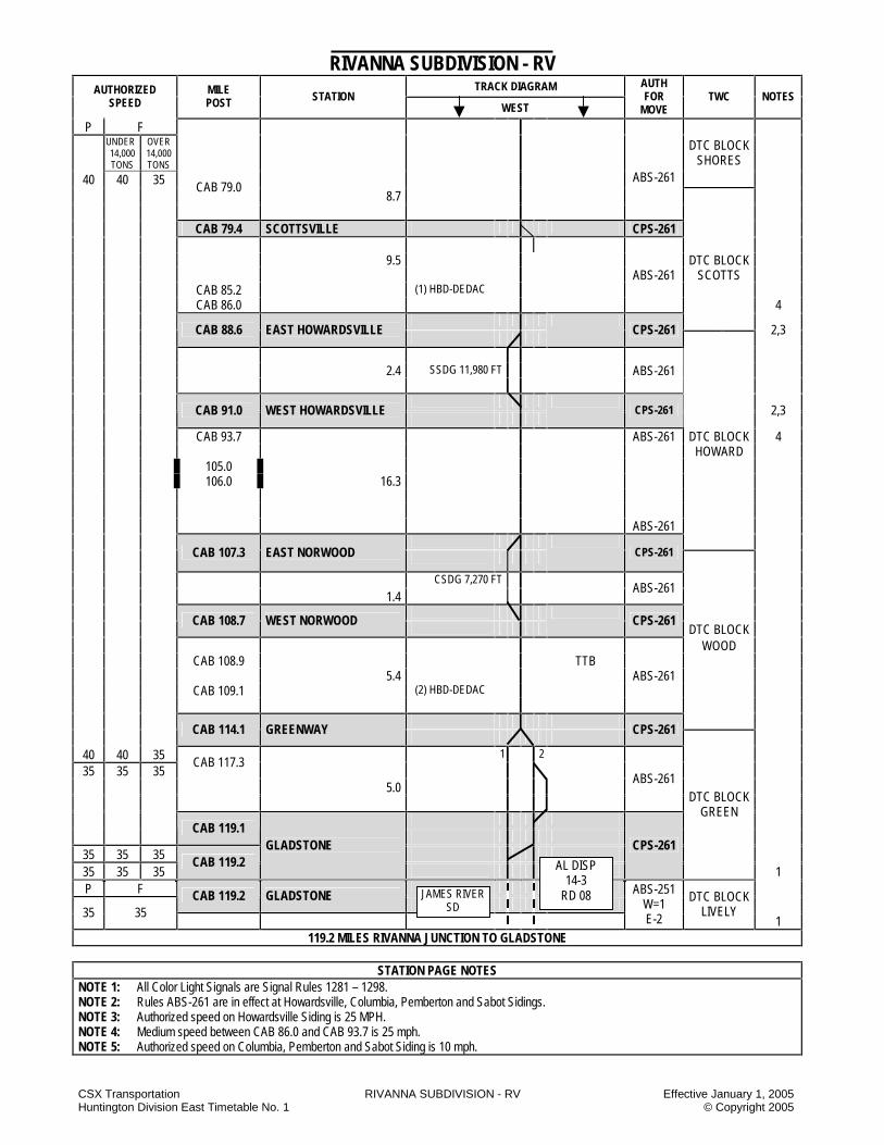
CSX Transportation RIVANNA SUBDIVISION - RV Effective January 1, 2005 Huntington Division East Timetable No. 1 © Copyright 2005
RIVANNA SUBDIVISION - RV TRACK DIAGRAM AUTHORIZED
SPEED MILE POST STATION
WEST
AUTH FOR
MOVE TWC NOTES
P F
UNDER 14,000 TONS
OVER 14,000 TONS
40 40 35
DTC BLOCK SHORES
CAB 79.0 8.7
ABS-261
CAB 79.4 SCOTTSVILLE CPS-261 9.5 DTC BLOCK ABS-261 SCOTTS CAB 85.2 (1) HBD-DEDAC CAB 86.0 4
CAB 88.6 EAST HOWARDSVILLE
CPS-261
2,3
2.4 SSDG 11,980 FT ABS-261
CAB 91.0 WEST HOWARDSVILLE
CPS-261
2,3
CAB 93.7 ABS-261 DTC BLOCK 4 HOWARD 105.0 106.0 16.3 ABS-261
CAB 107.3 EAST NORWOOD
CPS-261
CSDG 7,270 FT 1.4
ABS-261
CAB 108.7 WEST NORWOOD
CPS-261
DTC BLOCK WOOD CAB 108.9 TTB 5.4 ABS-261 CAB 109.1 (2) HBD-DEDAC
CAB 114.1 GREENWAY
CPS-261
40 40 35 1 2 35 35 35
CAB 117.3
5.0
ABS-261
CAB 119.1
35 35 35 35 35 35
CAB 119.2 GLADSTONE
CPS-261
DTC BLOCK GREEN
1 P F CAB 119.2 GLADSTONE
35 35
ABS-251 W=1 E-2
DTC BLOCK LIVELY
1 119.2 MILES RIVANNA JUNCTION TO GLADSTONE
STATION PAGE NOTES
NOTE 1: All Color Light Signals are Signal Rules 1281 – 1298. NOTE 2: Rules ABS-261 are in effect at Howardsville, Columbia, Pemberton and Sabot Sidings. NOTE 3: Authorized speed on Howardsville Siding is 25 MPH. NOTE 4: Medium speed between CAB 86.0 and CAB 93.7 is 25 mph. NOTE 5: Authorized speed on Columbia, Pemberton and Sabot Siding is 10 mph.
AL DISP 14-3
RD 08 JAMES RIVER SD

CSX Transportation RIVANNA SUBDIVISION - RV Effective January 1, 2005 Huntington Division East Timetable No. 1 © Copyright 2005
RIVANNA SUBDIVISION SPECIAL INSTRUCTIONS 1. INSTRUCTIONS RELATING TO OPERATING
RULE Excepted Tracks The following tracks are designated excepted tracks: No. 1 and No. 2 yard tracks and old airline main line tracks at Strathmore. Hand Brakes – Cars Rivanna Jct. or Browns Island – When leaving trains unattended at Rivanna Jct. or Brown’s Island, apply 10 hand brakes on cars. When selecting hand brakes select only hand brake toward the centerline. The inbound crew must inform the outbound crew the initial and number of the furthest car from the engine with a hand brake applied. Use Of Specified Tracks Gladstone – Nos. 1, 2, 3 and 4 tracks must not be blocked without instructions from the Lynchburg yardmaster. 2. INSTRUCTIONS RELATING TO SAFETY
RULES Protection Against Slips, Trips And Falls All timber refuge bays are out of service on the Richmond Viaduct between Rivanna Jct. and DX Cabin. Close Clearance Haxall Water Gate (CAB 2.4) – Richmond Water has installed new gate control handles on the south side of No. 1 track at CAB 2.4. These handles locate 5’ 3” from the centerline of No. 1 track at a height of ten (10) inches above the top of the rail. Crewmembers are cautioned against riding the south side of a car in the vicinity. Engineering Department employees are cautioned against equipment striking the handles. 3. INSTRUCTIONS RELATING TO COMPANY
POLICIES AND PROCEDURES
NONE 4. INSTRUCTION RELATING TO EQUIPMENT
HANDLING RULES Placing Empty Cars In Trains Empty cars, 80 feet or longer, must be handled on the rear of trains exceeding 13,400 tons.
5. INSTRUCTIONS RELATING TO AIR BRAKE
AND TRAIN HANDLING RULES NONE 6. INSTRUCTION RELATING TO EQUIPMENT
RESTRICTIONS Location Equipment Restriction
Korah Engines
Must not go beyond a point 390 feet west of point of switch
Luck Engines and cars
Must not operate under tipple
Gladstone-Caskie Industries
Six-axle units except radial
truck Must not operate
7. MISCELLANEOUS NONE
NOTES

CSX Transportation RUPERT SUBDIVISION - RT Effective January 1, 2005 Huntington Division East Timetable No. 1 © Copyright 2005
RUPERT SUBDIVISION - RT TRACK DIAGRAM AUTHORIZED
SPEED MILE POST STATION
WEST
AUTH FOR
MOVE TWC NOTES
10 96
10 CAF 20.4 RAINELLE JCT. 96
10 CAH 0.0 RAINELLE JCT.
96
0.2 CAH 0.2 WYE SWITCH 0.4 CAH 0.6 LINCOLN MINE 96
CAH 1.0 DTC BLOCK SIGN TWC-DTC DTC BLOCK RUPERT 6.6
CAH 7.2 DTC BLOCK SIGN RUPERT JCT.
3.8 CAH 9.9 GUMM 5,154 FT
DTC BLOCK ANJEAN 2.1 CAH 13.0 ANJEAN 6.9 TWC-DTC
CAH 19.9 DTC BLOCK SIGN CLEARCO
0.9 96 CAH 20.8 END OF TRACK
10 20.8 MILES RAINELLE JCT. TO END OF TRACK
BJ DISP 14-7
RD 08
SEWELL VALLEY SD
BJ DISP 14-7
RD 08
RADERS RUN IT

CSX Transportation RUPERT SUBDIVISION - RT Effective January 1, 2005 Huntington Division East Timetable No. 1 © Copyright 2005
RUPERT SUBDIVISION SPECIAL INSTRUCTIONS 1. INSTRUCTIONS RELATING TO OPERATING
RULES Excepted Tracks: The entire Rupert SD is designated as excepted track. Highway Crossing Protection All trains must STOP and flag the crossing at MP CAH 7.2. 2. INSTRUCTIONS RELATING TO SAFETY
RULES
NONE 3. INSTRUCTIONS RELATING TO COMPANY
POLICIES AND PROCEDURES
NONE 4. INSTRUCTIONS RELATING TO AIR BRAKE
AND TRAIN HANDLING RULES Stretch Braking Stretch braking is permitted between CAH 0.0 and CAH 10.0. 5. INSTRUCTIONS RELATING TO EQUIPMENT
HANDLING RULES
NONE 6. INSTRUCTIONS RELATING TO EQUIPMENT
RESTRICTIONS
NONE 7. MISCELLANEOUS 7.1 The distance between CAH 6.0 and CAH 7.0 is
6,336 feet. 7.2 Rupert SD between MP CAH 7.5 and end of track
CAH 19.9 is out of service. 7.3 Raders Run Industrial Track
NOTES
NOTES

CSX Transportation RUSSELL SUBDIVISION - RS Effective January 1, 2005 Huntington Division East Timetable No. 1 © Copyright 2005
RUSSELL SUBDIVISION - RS TRACK DIAGRAM AUTHORIZED
SPEED MILE POST STATION
WEST
AUTH FOR
MOVE TWC NOTES
P F
30 30 CA 524.2 RUSSELL YARD CPS-261
(193) DTC BLOCK
RUSSELL
1,2,3
CPS-261 PSGR MAIN
(193)
P F 60 30
RIVER LEAD PSGR MAIN
R13 R12 OLD YD LEAD
CA 524.2 RUSSELL YARD
1 SWT LEAD CPS-261 2 SWT LEAD (193)
1,7,8
1.9
ABS-261
FRT
CA 526.1 RACELAND
CPS-261
1
MAIN FRT MAIN P F 3 PULL OUT ABS-261 25 25 1.7 2 PULL OUT 1 PULL OUT CPS-261 (193) 1 2 3
60 30 25 25
CA 527.4 RJ CABIN
S LEAD 79 55 N LEAD
1,5,6
CPS-261
CA 527.8 POWELL STREET (193) 79 CA 528.8
ABS-261 70 CURVE
CA 529.0 DTC BLOCK 79 55 SILO
45 30 CA 530.8
3.9
CA 531.7 RIVERTON DTC BLOCK
45 30
CPS-261
GREEN
1,5,6
45 30 CA 532.8 1 2
ABS-261 DTC BLOCK
GREEN 1,5,6
7.5 MILES RUSSELL YARD TO RIVERTON
KANAWHA SD AN DISP.
20-3 RD 08
CR DISP. 94-4
RD 08
CR DISP. 94-4
RD 08 NORTHERN SD
1 2 3
1 2 3
3 2 1

CSX Transportation RUSSELL SUBDIVISION - RS Effective January 1, 2005 Huntington Division East Timetable No. 1 © Copyright 2005
STATION PAGE NOTES NOTE 1: Signal aspects displayed are in accordance with Signal Aspect Rules C1281 – C1298. NOTE 2: Between MP CA 524.0 and MP CA 501.0, trains in excess of 7,000 tons, but not exceeding 14,000 tons, will not exceed 40 MPH. NOTE 3: Between MP CA 524.0 and MP CA 501.0, trains in excess of 14,000 tons, will not exceed 35 MPH. NOTE 4: Between MP CA 527.8 and MP CA 531.7, trains in excess of 7,000 tons, but not exceeding 14,000 tons, will not exceed 40 MPH. NOTE 5: Between MP CA 527.8 and MP CA 531.7, trains in excess of 14,000 tons will not exceed 35 MPH. NOTE 6: Trains or engines operating on the engine runaround track between the ready track and the Big Four will not exceed 5 MPH. NOTE 7: Trains or engines operating through the Coal Hump engine underpass will not exceed 5 MPH.

CSX Transportation RUSSELL SUBDIVISION - RS Effective January 1, 2005 Huntington Division East Timetable No. 1 © Copyright 2005
RUSSELL SUBDIVISION SPECIAL INSTRUCTIONS 1. INSTRUCTIONS RELATING TO OPERATING
RULES Excepted Track: All tracks in Raceland Car Shop yard are excepted track. Time on Duty Westbound trains arriving at Russell and eastbound trains arriving at RJ Cabin will contact the Coal Hump yardmaster or the Big Four yardmaster and state the amount of time they have been on duty. Engine Bell The engine bell must be rung approaching and passing through the Coal Hump underpass on the south lead. Shoving Movements When the tracks listed below reach the car length limits specified, these tracks will be coupled and spotted at the clearance point of the track in accordance with Operating Rule 103-A: E01 through E20 – 50 car lengths E21 through E27 – 80 car lengths This is approximately 2/3 capacity for the above tracks. After the tracks specified have been spotted at the clearance point of the track and additional cars have been switched into these tracks, when an engine goes in to couple a track, all couplings will be observed by an employee at the coupling. The tracks will be coupled and stretched, and no other shoving movements will be made without protection. Hand Brakes Cars 1. Hand brakes will not be released on coal classifying
or coal receiving tracks until locomotive(s) are coupled onto the track or the double over is completed.
2. The following table lists exceptions to Operating Rule
103-D. These exceptions are the minimum number of hand brakes to be applied at that location.
NOTES
Russell Terminal Location Loaded Empty Comments Eastbound Yard R01 through T05
1 HB 2 HB Manifest or Mty Train
R01 through T05 4 HB -- Solid Loaded
Train E01 through E27
1 HB 1 HB --
Coal Rec Yard R10 through R18
--
New Yard N01 through N52
6 HB 4 HB
--
Old Manifest Yard M02, M03, M04, M29, M30, M32
2 HB 2 HB --
M05 Thru M28 1 HB 1 HB -- #1, #2, and #3 Main Tracks between CA 531.7 and CA 527.8
5 HB 3 HB 4 HB
Passenger Main between CA 527.8 and CA 524.2
5 HB 3 HB 4 HB
Freight Main between CA 527.8 and CA 526.1
5 HB 3 HB 4 HB
Hand-Operated Switches 1. The east Dogleg switch on south lead west of Coal
Hump must be left lined for straight track movement on the south lead.
2. The east end switch of the West Dogleg must be kept lined for straight track movement on the heavy side lead.
3. The west end switch of the West Dogleg must be kept lined for straight track movement on the south lead.
4. The switch on the south side of the hole (old manifest hump) must be kept lined for movement on the freight main.
5. The switch on the north side of the hole (old manifest hump) must be kept lined for movement on M01.
6. The cab track lead crossover must be kept lined for straight track movement when not in use.
7. The crossover at the west end of R02 and R01 must be kept lined for straight track movement when not in use.
8. The Creo lead switch must be kept lined for the north lead when not in use.
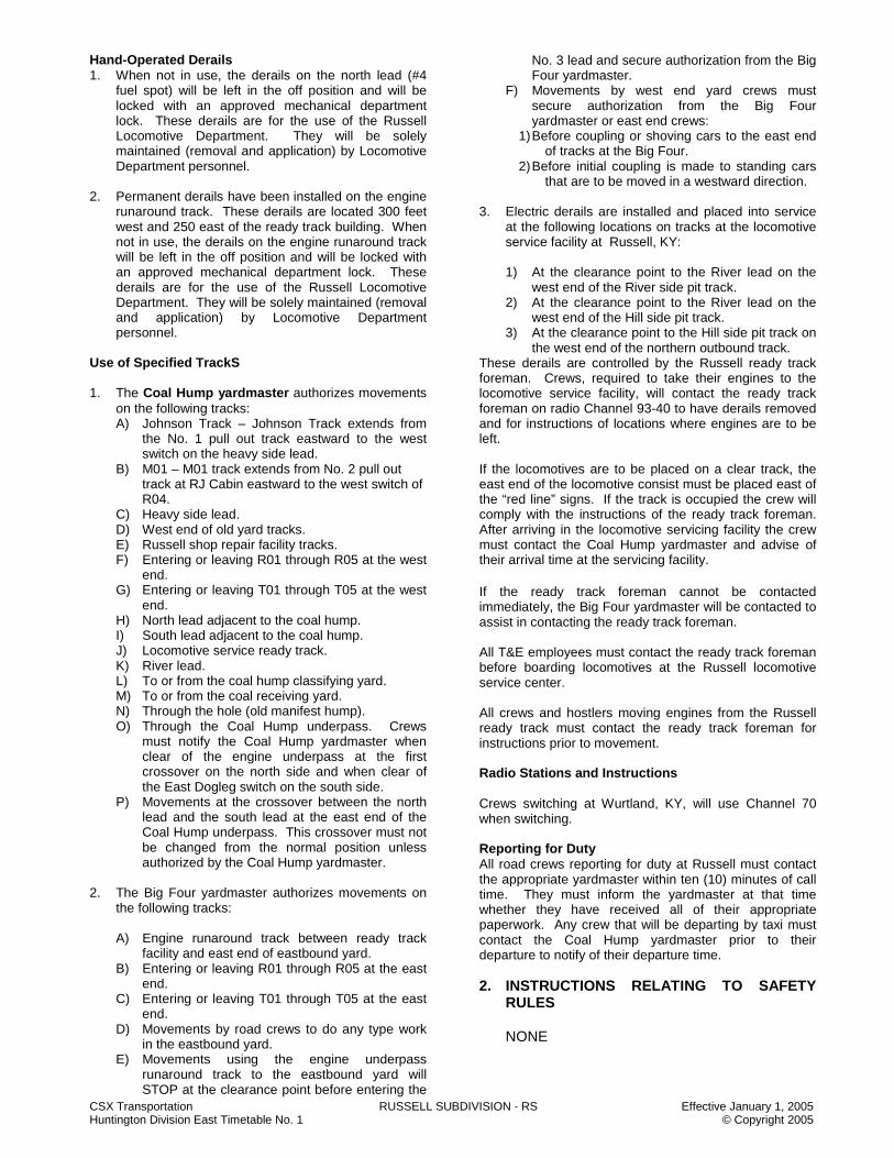
CSX Transportation RUSSELL SUBDIVISION - RS Effective January 1, 2005 Huntington Division East Timetable No. 1 © Copyright 2005
Hand-Operated Derails 1. When not in use, the derails on the north lead (#4
fuel spot) will be left in the off position and will be locked with an approved mechanical department lock. These derails are for the use of the Russell Locomotive Department. They will be solely maintained (removal and application) by Locomotive Department personnel.
2. Permanent derails have been installed on the engine
runaround track. These derails are located 300 feet west and 250 east of the ready track building. When not in use, the derails on the engine runaround track will be left in the off position and will be locked with an approved mechanical department lock. These derails are for the use of the Russell Locomotive Department. They will be solely maintained (removal and application) by Locomotive Department personnel.
Use of Specified TrackS 1. The Coal Hump yardmaster authorizes movements
on the following tracks: A) Johnson Track – Johnson Track extends from
the No. 1 pull out track eastward to the west switch on the heavy side lead.
B) M01 – M01 track extends from No. 2 pull out track at RJ Cabin eastward to the west switch of R04.
C) Heavy side lead. D) West end of old yard tracks. E) Russell shop repair facility tracks. F) Entering or leaving R01 through R05 at the west
end. G) Entering or leaving T01 through T05 at the west
end. H) North lead adjacent to the coal hump. I) South lead adjacent to the coal hump. J) Locomotive service ready track. K) River lead. L) To or from the coal hump classifying yard. M) To or from the coal receiving yard. N) Through the hole (old manifest hump). O) Through the Coal Hump underpass. Crews
must notify the Coal Hump yardmaster when clear of the engine underpass at the first crossover on the north side and when clear of the East Dogleg switch on the south side.
P) Movements at the crossover between the north lead and the south lead at the east end of the Coal Hump underpass. This crossover must not be changed from the normal position unless authorized by the Coal Hump yardmaster.
2. The Big Four yardmaster authorizes movements on
the following tracks:
A) Engine runaround track between ready track facility and east end of eastbound yard.
B) Entering or leaving R01 through R05 at the east end.
C) Entering or leaving T01 through T05 at the east end.
D) Movements by road crews to do any type work in the eastbound yard.
E) Movements using the engine underpass runaround track to the eastbound yard will STOP at the clearance point before entering the
No. 3 lead and secure authorization from the Big Four yardmaster.
F) Movements by west end yard crews must secure authorization from the Big Four yardmaster or east end crews:
1) Before coupling or shoving cars to the east end of tracks at the Big Four.
2) Before initial coupling is made to standing cars that are to be moved in a westward direction.
3. Electric derails are installed and placed into service
at the following locations on tracks at the locomotive service facility at Russell, KY:
1) At the clearance point to the River lead on the
west end of the River side pit track. 2) At the clearance point to the River lead on the
west end of the Hill side pit track. 3) At the clearance point to the Hill side pit track on
the west end of the northern outbound track. These derails are controlled by the Russell ready track foreman. Crews, required to take their engines to the locomotive service facility, will contact the ready track foreman on radio Channel 93-40 to have derails removed and for instructions of locations where engines are to be left. If the locomotives are to be placed on a clear track, the east end of the locomotive consist must be placed east of the “red line” signs. If the track is occupied the crew will comply with the instructions of the ready track foreman. After arriving in the locomotive servicing facility the crew must contact the Coal Hump yardmaster and advise of their arrival time at the servicing facility.
If the ready track foreman cannot be contacted immediately, the Big Four yardmaster will be contacted to assist in contacting the ready track foreman. All T&E employees must contact the ready track foreman before boarding locomotives at the Russell locomotive service center. All crews and hostlers moving engines from the Russell ready track must contact the ready track foreman for instructions prior to movement. Radio Stations and Instructions Crews switching at Wurtland, KY, will use Channel 70 when switching. Reporting for Duty All road crews reporting for duty at Russell must contact the appropriate yardmaster within ten (10) minutes of call time. They must inform the yardmaster at that time whether they have received all of their appropriate paperwork. Any crew that will be departing by taxi must contact the Coal Hump yardmaster prior to their departure to notify of their departure time. 2. INSTRUCTIONS RELATING TO SAFETY
RULES
NONE
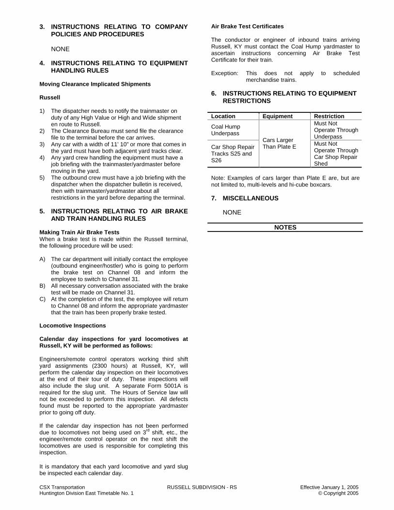
CSX Transportation RUSSELL SUBDIVISION - RS Effective January 1, 2005 Huntington Division East Timetable No. 1 © Copyright 2005
3. INSTRUCTIONS RELATING TO COMPANY POLICIES AND PROCEDURES
NONE
4. INSTRUCTIONS RELATING TO EQUIPMENT
HANDLING RULES Moving Clearance Implicated Shipments Russell 1) The dispatcher needs to notify the trainmaster on
duty of any High Value or High and Wide shipment en route to Russell.
2) The Clearance Bureau must send file the clearance file to the terminal before the car arrives.
3) Any car with a width of 11’ 10” or more that comes in the yard must have both adjacent yard tracks clear.
4) Any yard crew handling the equipment must have a job briefing with the trainmaster/yardmaster before moving in the yard.
5) The outbound crew must have a job briefing with the dispatcher when the dispatcher bulletin is received, then with trainmaster/yardmaster about all restrictions in the yard before departing the terminal.
5. INSTRUCTIONS RELATING TO AIR BRAKE
AND TRAIN HANDLING RULES Making Train Air Brake Tests When a brake test is made within the Russell terminal, the following procedure will be used: A) The car department will initially contact the employee
(outbound engineer/hostler) who is going to perform the brake test on Channel 08 and inform the employee to switch to Channel 31.
B) All necessary conversation associated with the brake test will be made on Channel 31.
C) At the completion of the test, the employee will return to Channel 08 and inform the appropriate yardmaster that the train has been properly brake tested.
Locomotive Inspections Calendar day inspections for yard locomotives at Russell, KY will be performed as follows: Engineers/remote control operators working third shift yard assignments (2300 hours) at Russell, KY, will perform the calendar day inspection on their locomotives at the end of their tour of duty. These inspections will also include the slug unit. A separate Form 5001A is required for the slug unit. The Hours of Service law will not be exceeded to perform this inspection. All defects found must be reported to the appropriate yardmaster prior to going off duty. If the calendar day inspection has not been performed due to locomotives not being used on 3rd shift, etc., the engineer/remote control operator on the next shift the locomotives are used is responsible for completing this inspection. It is mandatory that each yard locomotive and yard slug be inspected each calendar day.
Air Brake Test Certificates The conductor or engineer of inbound trains arriving Russell, KY must contact the Coal Hump yardmaster to ascertain instructions concerning Air Brake Test Certificate for their train. Exception: This does not apply to scheduled
merchandise trains. 6. INSTRUCTIONS RELATING TO EQUIPMENT
RESTRICTIONS Location Equipment Restriction
Coal Hump Underpass
Must Not Operate Through Underpass
Car Shop Repair Tracks S25 and S26
Cars Larger Than Plate E Must Not
Operate Through Car Shop Repair Shed
Note: Examples of cars larger than Plate E are, but are not limited to, multi-levels and hi-cube boxcars. 7. MISCELLANEOUS
NONE
NOTES

CSX Transportation RUSSELL SUBDIVISION - RS Effective January 1, 2005 Huntington Division East Timetable No. 1 © Copyright 2005
NOTES
NOTES

CSX Transportation SCOTTSLAWN SUBDIVISION - QT Effective January 1, 2005 Huntington Division East Timetable No. 1 © Copyright 2005
SCOTTSLAWN SECONDARY SUBDIVISION - QT TRACK DIAGRAM AUTHORIZED
SPEED MILE POST STATION
SOUTH
AUTH FOR
MOVE TWC NOTES
ABS-261
8,9
CPS-261 40
OVER DIAMOND QT 81.5 RIDGEWAY CPS-261
50 QT 82.3 CP 82
CPS-261 D 6
TWC-DCS
84.0 85.0
3.9 QT 86.2 HORTON 8.2 QT 92.4 HOOVER (2) HBD-DED D 4.9 QT 97.3 NORTH HONDA LEAD ss 7 0.2
QT 97.5 GAR D
0.2 BEAR SWAMP SDG ss 7 QT 97.7 SOUTH HONDA LEAD QT 104.1
50 QT 104.2
6.8 QT 104.5 MARYSVILLE
40 CURVES
50
QT 105.3
3.3 QT 106.2 N.E. WILLIS ss
1.5 7,575 FT 2
QT 107.8 WILLIS D POCKET
QT 108.3
1.9
QT 109.7 FLADT D
4.0 QT 113.7 ARNOLD (2) HBD-DED
50 6
IE DISP 46-1#
4 CLICKS
MT VICTORY SD
IE DISP 50-2#
5 CLICKS
HONDA IT
IE DISP 50-4#
4 CLICKS
O.M. SCOTT PLANT
TOLEDO BRANCH SD

CSX Transportation SCOTTSLAWN SUBDIVISION - QT Effective January 1, 2005 Huntington Division East Timetable No. 1 © Copyright 2005
SCOTTSLAWN SECONDARY SUBDIVISION - QT TRACK DIAGRAM AUTHORIZED
SPEED MILE POST STATION
SOUTH
AUTH FOR
MOVE TWC NOTES
6 50
TWC-DCS
1.6
3 QT 115.2 N.E. KILE 8,156 FT 1.5 QT 116.8 S.E. KILE D 3 1.2 QT 118.0 AMLIN 5.7 TWC-DCS
50 4,5 20
QT 123.7 CP DARBY
CPS-261 D 3
1.5 7,880 FT ABS-261
QT 125.2 S.E. HIGHWAY SIDING 3 1.1
20 30
QT 126.3 CP MOUNDS
CPS-261 D
ABS-261 3 QT 128.9 N.E. GRANDVIEW SDG 5,888 FT 1.1 3 130.0 S.E. GRANDVIEW SDG
131.0 1.3 30
131.2 ABS-261 6
25 131.3 CAMP
CPS-261 D
1
49.0 MILES CP 82 TO CAMP
STATION PAGE NOTES
NOTE 1: All signals are CR1277 to CR1294a. NOTE 2: Trains and engines will operate at restricted speed, not exceeding 15 MPH in Willis siding. NOTE 3: Trains and engines will operate at restricted speed, not exceeding 10 MPH in siding. NOTE 4: Between CP Darby and CP Buckeye (Western Lead), trains and engines will not exceed 30 MPH. NOTE 5: Between CP Darby and CP Buckeye (Western Lead), Rule ABS-261 is in effect. NOTE 6: Loaded grain and mineral unit trains or mixed freight trains with 30 or more loaded grain or mineral cars must not exceed 40 MPH. NOTE 7: Whenever cars are set off or left standing on the Honda lead track between MP 0.0 and Bear Swamp Road, the divider switch for the south leg must be lined and locked for the south leg. NOTE 8: Trains and engines will not exceed 30 MPH while operating on the northwest and southwest connecting tracks at CP 124. NOTE 9: Trains and engines will not exceed 10 MPH while operating on the southeast connecting track at CP 124.
TO NS BUCKEYE YD
WESTERN LEAD TO VAN YARD
IE DISP 50-2#
3 CLICKS
NS DISP RD 58 925 #
NS CINCINNATI
LINE
NS RR
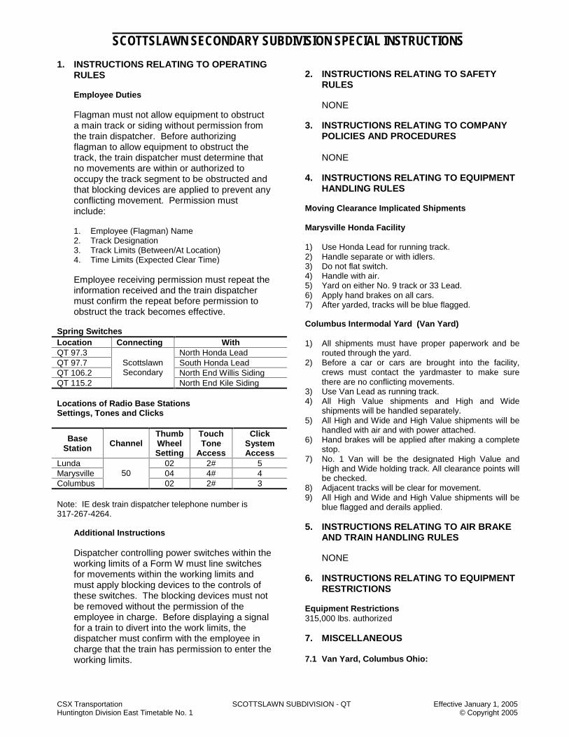
CSX Transportation SCOTTSLAWN SUBDIVISION - QT Effective January 1, 2005 Huntington Division East Timetable No. 1 © Copyright 2005
SCOTTSLAWN SECONDARY SUBDIVISION SPECIAL INSTRUCTIONS 1. INSTRUCTIONS RELATING TO OPERATING
RULES Employee Duties Flagman must not allow equipment to obstruct a main track or siding without permission from the train dispatcher. Before authorizing flagman to allow equipment to obstruct the track, the train dispatcher must determine that no movements are within or authorized to occupy the track segment to be obstructed and that blocking devices are applied to prevent any conflicting movement. Permission must include: 1. Employee (Flagman) Name 2. Track Designation 3. Track Limits (Between/At Location) 4. Time Limits (Expected Clear Time) Employee receiving permission must repeat the information received and the train dispatcher must confirm the repeat before permission to obstruct the track becomes effective.
Spring Switches Location Connecting With QT 97.3 North Honda Lead QT 97.7 South Honda Lead QT 106.2 North End Willis Siding QT 115.2
Scottslawn Secondary
North End Kile Siding Locations of Radio Base Stations Settings, Tones and Clicks
Base Station Channel
Thumb Wheel Setting
Touch Tone
Access
Click System Access
Lunda 02 2# 5 Marysville 04 4# 4 Columbus
50 02 2# 3
Note: IE desk train dispatcher telephone number is 317-267-4264.
Additional Instructions Dispatcher controlling power switches within the working limits of a Form W must line switches for movements within the working limits and must apply blocking devices to the controls of these switches. The blocking devices must not be removed without the permission of the employee in charge. Before displaying a signal for a train to divert into the work limits, the dispatcher must confirm with the employee in charge that the train has permission to enter the working limits.
2. INSTRUCTIONS RELATING TO SAFETY
RULES
NONE 3. INSTRUCTIONS RELATING TO COMPANY
POLICIES AND PROCEDURES
NONE 4. INSTRUCTIONS RELATING TO EQUIPMENT
HANDLING RULES Moving Clearance Implicated Shipments Marysville Honda Facility 1) Use Honda Lead for running track. 2) Handle separate or with idlers. 3) Do not flat switch. 4) Handle with air. 5) Yard on either No. 9 track or 33 Lead. 6) Apply hand brakes on all cars. 7) After yarded, tracks will be blue flagged. Columbus Intermodal Yard (Van Yard) 1) All shipments must have proper paperwork and be
routed through the yard. 2) Before a car or cars are brought into the facility,
crews must contact the yardmaster to make sure there are no conflicting movements.
3) Use Van Lead as running track. 4) All High Value shipments and High and Wide
shipments will be handled separately. 5) All High and Wide and High Value shipments will be
handled with air and with power attached. 6) Hand brakes will be applied after making a complete
stop. 7) No. 1 Van will be the designated High Value and
High and Wide holding track. All clearance points will be checked.
8) Adjacent tracks will be clear for movement. 9) All High and Wide and High Value shipments will be
blue flagged and derails applied. 5. INSTRUCTIONS RELATING TO AIR BRAKE
AND TRAIN HANDLING RULES NONE 6. INSTRUCTIONS RELATING TO EQUIPMENT
RESTRICTIONS Equipment Restrictions 315,000 lbs. authorized 7. MISCELLANEOUS 7.1 Van Yard, Columbus Ohio:
CSX Transportation SCOTTSLAWN SUBDIVISION - QT Effective January 1, 2005 Huntington Division East Timetable No. 1 © Copyright 2005
A) Before entering or departing the Van yard, trains and engines must secure instructions of the yardmaster, Van yard, on Channel 25.
B) Movements in Van yard will be made at restricted speed, not exceeding 10 MPH.
7.2 The Western Lead extends from MP QTB 3.3 to MP QTB 4.5
7.3 Industrial Tracks
The Honda industrial track extends between MP QTH 0.0 and MP QTH 8.0.
NOTES
NOTES

CSX Transportation SETH SUBDIVISION –S5 Effective January 1, 2005 Huntington Division East Timetable No. 1 © Copyright 2005
SETH SUBDIVISION - S5 TRACK DIAGRAM AUTHORIZED
SPEED MILE POST STATION
WEST
AUTH FOR
MOVE TWC NOTES
END OF TRACK CLN 10.2
96
0.9 CLN 9.3 PRENTER 96
CLN 9.2 DTC BLOCK SIGN TWC-DTC 10
DTC BLOCK SETH TWC-DTC
CLN 1.5 DTC BLOCK SIGN 193 YL 9.2
10 CLN 0.0 SETH 193 YL
25 CLL 20.9 SETH
TWC-DTC
DTC BLOCK OAK TWC-DTC
10.2 MILES END OF TRACK TO SETH
BJ DISP 14-2
RD 08
BIG COAL SD
BJ DISP 14-2
RD 08

CSX Transportation SETH SUBDIVISION –S5 Effective January 1, 2005 Huntington Division East Timetable No. 1 © Copyright 2005
SETH SUBDIVISION SPECIAL INSTRUCTIONS 1. INSTRUCTIONS RELATING TO OPERATING RULES Excepted Tracks The entire Seth SD is designated as excepted track. Hand Brakes Cars The following table lists exceptions to Operating Rule 103-D. These exceptions are the minimum number of hand brakes to be applied at that location.
Location Loaded Empty Comments Prenter 50% 30% --
Hand-Operated Switches The normal position of the apex switch at Seth is lined for movement to the west leg of the wye. 2. INSTRUCTIONS RELATING TO SAFETY
RULES Exceptions to Making A Safety STOP Employees will make the safety STOP as required by Safety Rule 2201 in all cases except at the locations described below: 1) Seth SD – When doubling up loaded trains at
Prenter Mine. Crews doubling up loaded trains at the above listed locations must comply with safety rules and SOFA recommendations except for Safety Rule 2201 (safety stop) and must comply with the following: 1) Safety Rule 2001 - A job briefing must be conducted
in which the movement to be made is discussed. 2) Safety Rule 2201 - Employees must not ride to the
coupling. 3) Safety Rule 2101 - Employees must not mount or
dismount moving equipment. 4) Operating Rule 421 - When radios are
used for communication, crews must give clear and accurate car lengths for the movement to be made
3. INSTRUCTIONS RELATING TO COMPANY
POLICIES AND PROCEDURES
NONE 4. INSTRUCTIONS RELATING TO AIR BRAKE
AND TRAIN HANDLING RULES
NONE
5. INSTRUCTIONS RELATING TO EQUIPMENT HANDLING RULES
NONE
6. INSTRUCTIONS RELATING TO EQUIPMENT
RESTRICTIONS
NONE 7. MISCELLANEOUS
NONE
NOTES

CSX Transportation SEWELL VALLEY SUBDIVISION - SY Effective January 1, 2005 Huntington Division East Timetable No. 1 © Copyright 2005
SEWELL VALLEY SUBDIVISION - SY TRACK DIAGRAM AUTHORIZED
SPEED MILE POST STATION
WEST
AUTH FOR
MOVE TWC NOTES
DTC BLOCK
P F CAMPBELL 60 50 CA 370.0 MEADOW CREEK
ABS-261
1
193 10 CAF 0.0 MEADOW CREEK
1.2 193
CAF 1.2 DTC BLOCK SIGN ALPHA TWC-DTC
7.0 CAF 8.2 MEADOW BRIDGE DTC BLOCK 0.4 ALPHA CAF 8.6 HAWLEY 1,900 FT
CAF 8.7 DTC BLOCK SIGN 2.9 CAF 11.5 SPRINGDALE DTC BLOCK 6.6 SHAVER TWC-DTC
CAF 18.1 DTC BLOCK SIGN WOODY 96
0.1 2,500 FT CAF 18.2 FARM SIDING 1.1 CAF 19.3 RAINELLE 1.1 CAF 20.4 RAINELLE JCT. 0.2 CAF 20.6 G&E JCT. 1.4 96
CAF 22.0 DTC BLOCK SIGN MP 22.0 ABS-261
16.4 DTC BLOCK CAF 37.4 BABCOCK NALLEN 2.0
CAF 39.4 DTC BLOCK SIGN NALLEN
4.1 CAF 43.5 RUSS JCT. DTC BLOCK 0.1 CARN
10 CAF 43.6
END OF MAIN TRACK ABS-261
43.6 MILES MEADOW CREEK TO END OF TRACK
STATION PAGE NOTES NOTE 1: Signals displayed are in accordance with Signal Aspect Rules C1281 - C1298.
GLADE CREEK IT
G&E SD
RUPERT SD BJ DISP
14-7 RD 08
NEW RIVER SD AM DISP 14-8
RD 08

CSX Transportation SEWELL VALLEY SUBDIVISION - SY Effective January 1, 2005 Huntington Division East Timetable No. 1 © Copyright 2005
SEWELL VALLEY SUBDIVISION SPECIAL INSTRUCTIONS 1. INSTRUCTIONS RELATING TO OPERATING
RULES Highway Crossings at Grade Rainelle – In addition to complying with Rule 100-E, eastbound trains and engines will not exceed 2 MPH when stopped or delayed within 400 feet of U.S. Route 60 crossing or when approaching the crossing at a speed of less than 8 MPH. Hawley – Trains or engines entering or leaving Hawley passing siding at either end will not move over the highway crossing unless the movement is protected by an employee stationed at the road crossing. Highway Crossing Protection All trains must STOP and flag Rt. 41 road crossing (Nallen) at MP CAF 39.3. Hand-Operated Switches G&E Jct. – The normal position is for movement to G&E SD. Russ Jct. – The normal position is for movement to Glade Creek IT.
2. INSTRUCTIONS RELATING TO SAFETY
RULES Close Clearance Employees are prohibited from riding the side of equipment at the following locations: A) Meadow Creek – Between Wendy No. 2 and the
retaining wall north side, 20 car lengths east of Wendy derail.
3. INSTRUCTIONS RELATING TO COMPANY
POLICIES AND PROCEDURES
NONE
4. INSTRUCTIONS RELATING TO EQUIPMENT
HANDLING RULES
NONE
5. INSTRUCTIONS RELATING TO AIR BRAKE
AND TRAIN HANDLING RULES Running Dynamic Brake Test Procedures 2-unit consist:
With the locomotive consist moving, go to dynamic braking and determine that the lead locomotive is operative and producing a retarding effect. After determining the lead locomotive is operative, isolate the lead unit and apply the dynamic brake. 3-unit (or more) consist: With the locomotive consist moving, go to dynamic braking and determine that the lead locomotive is operative and producing a retarding effect. After determining the lead locomotive is operative, isolate the lead unit and the third unit and use the same procedure to determine if the second unit develops a retarding effect. If the axle count dictates a third unit is needed, the second locomotive must be isolated and it must be determined that the third unit develops a retarding effect. During this verification, employees may position themselves on the appropriate unit to observe it’s retarding effect and communicate results to the entire crew. If additional units are required, the same process will be used to test each additional unit.
Grade Operation A) Glade Creek IT – Caren to Russ Jct. Retainers will be turned up on the head end on a minimum of 50 percent of loaded cars. The use of retainers is not required provided the train is handled by not less than two locomotives, equipped with operable dynamic brakes and pressure maintaining.
B) Sewell Valley SD
1 No more than 90 empty coal cars will be
handled between MP CAF 0.0 and MP CAF 14.0.
2 Stretch braking is permitted between CAF 15.0 and CAF 30.0.
Grade Operation A) Springdale – Meadow Creek
Before starting down grade the between Springdale and Meadow Creek, retainers on loaded cars must be set in the high pressure position. Retainers on empty cars must be set in the low pressure position, except retainers need not be used on empty cars if the number of empty cars in the train does not exceed 20 percent of the total.
CSX Transportation SEWELL VALLEY SUBDIVISION - SY Effective January 1, 2005 Huntington Division East Timetable No. 1 © Copyright 2005
When cars are picked up on line of road, brakes must be tested. Retainers on such cars picked up by eastbound trains must be tested to know they are operative.
The engineer of an eastbound train, when one or more cars are added to the train at Springdale or points between Springdale and Meadow Creek, after the train line is coupled through entire train, will wait twenty minutes before starting the train in order to make sure that all reservoirs are fully charged. In addition to the requirements of Item A above, the dynamic brake must be tested prior to descending the grade between Springdale and Meadow Creek. 6. INSTRUCTIONS RELATING TO EQUIPMENT
RESTRICTIONS Location Equipment Restriction
Entire SD
Six-axle Units Unless Equipped With Radial Or
Steerable Trucks
Must Not Operate
Caren – Glade Creek Meadow River #1 Mine
Equipment Other Than Coal Cars
Must Not Operate Under Loading Facility
7. MISCELLANEOUS 7.1 Rainelle WV – Signs have been erected indicating
the entrance to the designated locomotive servicing area.
7.2 Glade Creek Industrial Track
NOTES
NOTES

CSX Transportation SEWELL VALLEY SUBDIVISION - SY Effective January 1, 2005 Huntington Division East Timetable No. 1 © Copyright 2005
NOTES
NOTES

CSX Transportation SHORT LINE SUBDIVISION - SO Effective January 1, 2005 Huntington Division East Timetable No. 1 © Copyright 2005
SHORT LINE SUBDIVISION - SO TRACK DIAGRAM AUTHORIZED
SPEED MILE POST STATION
WEST
AUTH FOR
MOVE TWC NOTES
ABS-261 35
BA 303.4 J TOWER
CPS-261
DTC BLOCK CLARK
TWC-DTC
25 BNA 58.2 J TOWER
BNA 52.4
15 4.9 DTC BLOCK
25 BNA 51.6
SHORT 54.0 53.1 HEPZIBAH 53.0
BNA 48.9 DTC BLOCK SIGN 4.3
BNA 48.8 LUMBERPORT HAYWOOD BNA 48.5 (1) HBD-DED
DTC BLOCK ROBRUN
BNA 45.5 DTC BLOCK SIGN
1 BNA 44.8
BNA 44.6 BNA 40.9 9.2
BNA 40.8 DTC BLOCK
BNA 40.4 DOLA BNA 40.3
BNA 40.1 BNA 39.6 IRVING 5,000 FT
BNA 39.2 DTC BLOCK SIGN 17.3 BNA 35.9
BNA 35.4
HARTZEL TUNNEL NO. 3
BNA 29.3 DTC BLOCK
BNA 25.0 HART
BNA 23.4 (1) HBD-DED 2 BNA 23.0
BNA 22.3 JACKSONBURG 6,100 FT BNA 21.8 DTC BLOCK SIGN
BNA 21.7
BNA 19.8 DTC BLOCK BNA 17.8 PINE GROVE TYLER
BNA 16.3
BNA 16.1 2.9 BNA 15.5 DTC BLOCK SIGN BNA 14.9 ALLEN
5,500 FT BNA 14.3 ss
BNA 12.1 BNA 11.7
TWIN TUNNEL NO. 2
BNA 11.4 DTC BLOCK BNA 11.3
TWIN TUNNEL NO. 1 BARD
BNA 10.9
BNA 10.7 BNA 4.7 BARD
4.0 3.0
25 BNA 2.6 4.7 TWC-DTC
CJ DISP 14-3
RD 08
CJ DISP 14-8
RD 08
HAYWOOD IT
BRIDGEPORT SD
ROBINSON RUN IT
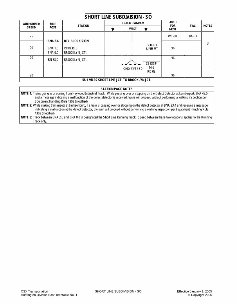
CSX Transportation SHORT LINE SUBDIVISION - SO Effective January 1, 2005 Huntington Division East Timetable No. 1 © Copyright 2005
SHORT LINE SUBDIVISION - SO TRACK DIAGRAM AUTHORIZED
SPEED MILE POST STATION
WEST
AUTH FOR
MOVE TWC NOTES
25
TWC-DTC BARD
BNA 2.6 DTC BLOCK SIGN
3 BNA 1.0 ROBERTS
SHORT LINE RT 96 20
BNA 0.0 BROOKLYN JCT.
96 20 BN 38.0 BROOKLYN JCT.
OHIO RIVER SD
20 96 58.1 MILES SHORT LINE JCT. TO BROOKLYN JCT.
STATION PAGE NOTES
NOTE 1: Trains going to or coming from Haywood Industrial Track: While passing over or stopping on the Defect Detector at Lumberport, BNA 48.5, and a message indicating a malfunction of the defect detector is received, trains will proceed without performing a walking inspection per Equipment Handling Rule 4303 (modified).
NOTE 2: While making train meets at Jacksonburg, if a train is passing over or stopping on the defect detector at BNA 23.4 and receives a message indicating a malfunction at the defect detector, the train will proceed without performing a walking inspection per Equipment Handling Rule 4303 (modified).
NOTE 3: Track between BNA 2.6 and BNA 0.0 is designated the Short Line Running Track. Speed between these two locations applies to the Running Track only.
CJ DISP 14-5
RD 08
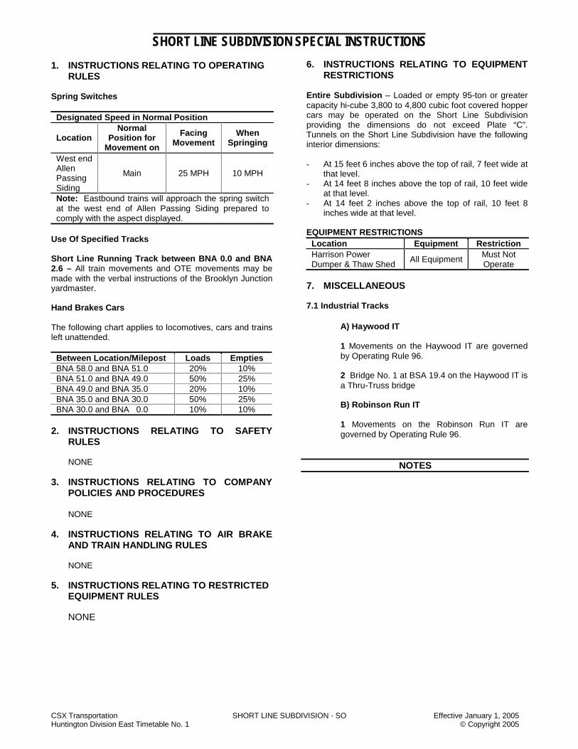
CSX Transportation SHORT LINE SUBDIVISION - SO Effective January 1, 2005 Huntington Division East Timetable No. 1 © Copyright 2005
SHORT LINE SUBDIVISION SPECIAL INSTRUCTIONS
1. INSTRUCTIONS RELATING TO OPERATING RULES
Spring Switches
Designated Speed in Normal Position
Location Normal
Position for Movement on
Facing Movement
When Springing
West end Allen Passing Siding
Main 25 MPH 10 MPH
Note: Eastbound trains will approach the spring switch at the west end of Allen Passing Siding prepared to comply with the aspect displayed.
Use Of Specified Tracks Short Line Running Track between BNA 0.0 and BNA 2.6 – All train movements and OTE movements may be made with the verbal instructions of the Brooklyn Junction yardmaster. Hand Brakes Cars The following chart applies to locomotives, cars and trains left unattended.
Between Location/Milepost Loads Empties BNA 58.0 and BNA 51.0 20% 10% BNA 51.0 and BNA 49.0 50% 25% BNA 49.0 and BNA 35.0 20% 10% BNA 35.0 and BNA 30.0 50% 25% BNA 30.0 and BNA 0.0 10% 10%
2. INSTRUCTIONS RELATING TO SAFETY
RULES NONE 3. INSTRUCTIONS RELATING TO COMPANY
POLICIES AND PROCEDURES
NONE 4. INSTRUCTIONS RELATING TO AIR BRAKE
AND TRAIN HANDLING RULES
NONE 5. INSTRUCTIONS RELATING TO RESTRICTED
EQUIPMENT RULES NONE
6. INSTRUCTIONS RELATING TO EQUIPMENT
RESTRICTIONS Entire Subdivision – Loaded or empty 95-ton or greater capacity hi-cube 3,800 to 4,800 cubic foot covered hopper cars may be operated on the Short Line Subdivision providing the dimensions do not exceed Plate “C”. Tunnels on the Short Line Subdivision have the following interior dimensions: - At 15 feet 6 inches above the top of rail, 7 feet wide at
that level. - At 14 feet 8 inches above the top of rail, 10 feet wide
at that level. - At 14 feet 2 inches above the top of rail, 10 feet 8
inches wide at that level. EQUIPMENT RESTRICTIONS
Location Equipment Restriction Harrison Power Dumper & Thaw Shed
All Equipment Must Not Operate
7. MISCELLANEOUS 7.1 Industrial Tracks
A) Haywood IT 1 Movements on the Haywood IT are governed by Operating Rule 96. 2 Bridge No. 1 at BSA 19.4 on the Haywood IT is a Thru-Truss bridge B) Robinson Run IT 1 Movements on the Robinson Run IT are governed by Operating Rule 96.
NOTES

CSX Transportation SHORT LINE SUBDIVISION - SO Effective January 1, 2005 Huntington Division East Timetable No. 1 © Copyright 2005
NOTES
NOTES

CSX Transportation STONY RIVER SUBDIVISION - SR Effective January 1, 2005 Huntington Division East Timetable No. 1 © Copyright 2005
STONY RIVER SUBDIVISION - SR TRACK DIAGRAM AUTHORIZED
SPEED MILE POST STATION
WEST
AUTH FOR
MOVE TWC NOTES
25 193 YL
25 BAH 62.0 BAYARD
193 YL
10
BUA 0.0 BAYARD
BUA 0.2 0.2
193 YL
BUA 1.0 DTC BLOCK SIGN TWC-DTC
3.2 DTC BLOCK BUA 3.2 NORTH BRANCH ARM ABTH 5559
BUA 3.9 DTC BLOCK SIGN
10.2 10
15 10 BUA 8.7
1
DTC BLOCK BUA12.3 12.3 STO BUA 13.4 GATZMER MINE
BUA 16.7 DTC BLOCK SIGN STONY RIVER
6.5
15 10 TWC-DTC 1
END OF TRACK
16.7 MILES BAYARD TO STONY RIVER
STATION PAGE DIAGRAM NOTES
NOTE 1: Eastbound loaded trains-10 MPH.
CI DISP 14-5
RD 08
EAST
BOU
ND
LO
ADED
TR
AIN
S THOMAS SD
CI DISP 14-5
RD 08

CSX Transportation STONY RIVER SUBDIVISION - SR Effective January 1, 2005 Huntington Division East Timetable No. 1 © Copyright 2005
STONY RIVER SUBDIVISION - SR
1. INSTRUCTIONS RELATING TO OPERATING RULES
Hand Brakes Cars 1. The following chart applies to trains standing on a
heavy grade, with a locomotive attached and the crew stays with the train.
Between Location/Milepost Loads Empties BUA 0.0 and BUA 12.3 30% 10%
2. The following chart applies to locomotives, cars, and
trains left unattended.
Between Location/Milepost Loads Empties BUA 0.0 and BUA 16.7 75% 35%
2. INSTRUCTIONS RELATING TO SAFETY
NONE 3. INSTRUCTIONS RELATING TO COMPANY
POLICIES AND PROCEDURES
NONE 4. INSTRUCTIONS RELATING TO EQUIPMENT
HANDLING RULES NONE 5. INSTRUCTIONS RELATING TO AIR BRAKE
AND TRAIN HANDLING RULES Tractive Effort Helpers Entire Subdivision – A helper consist attached to the rear of the train will not exceed 18 axles. 6. INSTRUCTIONS RELATING TO EQUIPMENT
RESTRICTIONS Location Equipment Restriction
Entire SD Non-Radial Truck Six-axle units
Must Not Operate
Stony River Power Plant Cars
Must not move cars standing west of thawing
shed or dumper
7. MISCELLANEOUS NONE
NOTES
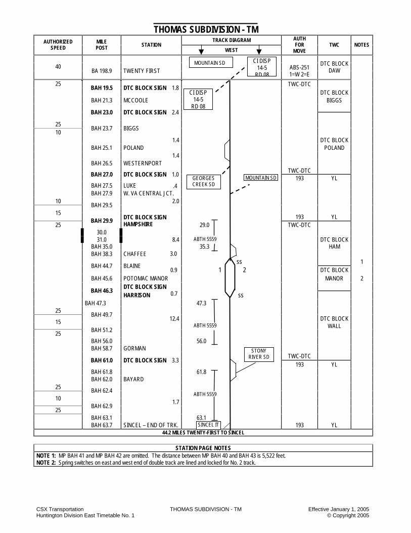
CSX Transportation THOMAS SUBDIVISION - TM Effective January 1, 2005 Huntington Division East Timetable No. 1 © Copyright 2005
THOMAS SUBDIVISION - TM TRACK DIAGRAM AUTHORIZED
SPEED MILE POST STATION
WEST
AUTH FOR
MOVE TWC NOTES
40
BA 198.9 TWENTY FIRST
ABS-251 1=W 2=E
DTC BLOCK DAW
TWC-DTC 25 BAH 19.5 DTC BLOCK SIGN 1.8
DTC BLOCK BAH 21.3 MCCOOLE BIGGS
BAH 23.0 DTC BLOCK SIGN 2.4
25 10
BAH 23.7 BIGGS
1.4 DTC BLOCK BAH 25.1 POLAND POLAND 1.4 BAH 26.5 WESTERNPORT TWC-DTC
BAH 27.0 DTC BLOCK SIGN 1.0 193 YL
BAH 27.5 LUKE BAH 27.9 W. VA CENTRAL JCT.
10 2.0
BAH 29.5
15
193 YL 25
BAH 29.9 DTC BLOCK SIGN HAMPSHIRE 29.0 TWC-DTC
30.0 31.0 8.4 ABTH 5559 DTC BLOCK BAH 35.0 35.3 HAM BAH 38.3 CHAFFEE
ss 1
BAH 44.7 BLAINE 1 2 DTC BLOCK
BAH 45.6 POTOMAC MANOR MANOR 2 DTC BLOCK SIGN
BAH 46.3 HARRISON ss
BAH 47.3 47.3
25
BAH 49.7 12.4 DTC BLOCK 15
ABTH 5559 WALL 25
BAH 51.2
BAH 56.0 56.0 BAH 58.7 GORMAN
TWC-DTC
BAH 61.0 DTC BLOCK SIGN 3.3 193 YL
BAH 61.8 61.8 BAH 62.0 BAYARD
25 BAH 62.4
ABTH 5559 10
1.7
25
BAH 62.9
BAH 63.1 63.1 BAH 63.7 SINCEL – END OF TRK. 193 YL
44.2 MILES TWENTY-FIRST TO SINCEL
STATION PAGE NOTES NOTE 1: MP BAH 41 and MP BAH 42 are omitted. The distance between MP BAH 40 and BAH 43 is 5,522 feet. NOTE 2: Spring switches on east and west end of double track are lined and locked for No. 2 track.
SINCEL IT
STONY RIVER SD
.4
3.0
0.9
CI DISP 14-5
RD 08
MOUNTAIN SD
CI DISP 14-5
RD 08
MOUNTAIN SD GEORGES CREEK SD
0.7
CSX Transportation THOMAS SUBDIVISION - TM Effective January 1, 2005 Huntington Division East Timetable No. 1 © Copyright 2005
THOMAS SUBDIVISION SPECIAL INSTRUCTIONS
1. INSTRUCTIONS RELATING TO OPERATING RULES
Spring Switches Table Spring Switches
Location Normal Position
Facing Speed
When Springing
Blaine (EEDT) No. 1 track Harrison (EEDT) No. 2 track
25 25
Flagging When necessary to provide rear end protection, the flagman must go back not less than the following distance:
Table: Flagging Distance Between Direction of Train Distance BAH 29.9 and BAH 69.0 Eastbound 7,900 ft
Highway Crossings at Grade Due to rusty rail conditions, be sure highway crossing signals are working properly before passing over crossings. Obstructions Between the following locations, trains must operate prepared to STOP short of obstructions, looking out for rocks or slides coming in on track. Proceed at authorized speed providing track is clear. BAH 29.9 and BAH 31.5 BAH 45.2 and BAH 45.5 BAH 47.5 and BAH 47.6 Hand Brakes Cars The following chart applies to trains standing on a heavy grade, with the locomotive attached, and the crew stays with the train.
Between Location /Milepost Loads Empties BAH 29.0 and BAH 35.3 BAH 47.3 and BAH 56.0 BAH 61.8 and BAJ 63.1
30% 10%
The following chart applies to locomotives, cars, and trains left unattended. Between Location/Milepost Loads Empties BAH 19.5 and BAH 19.8 50% 25% BAH 19.8 and BAH 28.4 25% 15% BAH 28.4 and BAH 35.2 75% 35% BAH 35.2 and BAH 40.0 25% 15% BAH 40.0 and BAH 46.0 35% 25% BAH 46.0 and BAH 56.6 75% 35% BAH 56.6 and BAH 58.0 50% 25% BAH 58.0 and BAH 61.0 30% 20% BAH 61.0 and Mattiki 50% 35% Hand-Operated Switches 1. Mettiki Mine – No. 3 Hill Track – The hinge type
derail at the west end will be applied whenever a train is moved from Mettiki and the split-rail derail on the east end of No. 3 track will be left in the non-derailing position.
2. Trains will approach the main track switch governing movement to the Georges Creek Subdivision expecting to find it lined against their movement. Switch will be relined and locked for movement on the Thomas Subdivision.
2. INSTRUCTIONS RELATING TO SAFETY
RULES Mounting and Dismounting Moving Equipment Employees will STOP the movement before mounting or dismounting equipment, except: 1) Thomas SD-
Loaded trains departing Mettiki Mine. Exceptions to Making A Safety STOP Employees will make the safety STOP as required by Safety Rule 2201 in all cases except at the locations described below: 1) BAH 28.0 WV Central Junction
4 Track in mill 13 Track in mill
When shoving a cut of cars west (5 or more loaded cars) on any yard tracks (1 through 25), a safety STOP will not be required west of the No. 9 lead switch if a trainman is located on the ground at the coupling.
Crews doubling up loaded trains at the above listed locations must comply with safety rules and SOFA recommendations except for Safety Rule 2201 (safety STOP) and must comply with the following: 1) Safety Rule 2001 - A job briefing must be conducted
in which the movement to be made is discussed. 2) Safety Rule 2201 - Employees must not ride to the
coupling.

CSX Transportation THOMAS SUBDIVISION - TM Effective January 1, 2005 Huntington Division East Timetable No. 1 © Copyright 2005
3) Safety Rule 2101 - Employees must not mount or dismount moving equipment.
4) Operating Rule 421 - When radios are used for communication, crews must give clear and accurate car lengths for the movement to be made.
3. INSTRUCTIONS RELATING TO COMPANY
POLICIES AND PROCEDURES
NONE 4. INSTRUCTIONS RELATING TO EQUIPMENT
HANDLING RULES Handling Cars That Are Prone To Rocking Trains handling Plate “F” box cars, high side gondolas, open top hoppers or covered hoppers loaded with 95 tons or more and having a cubic capacity of 4,000 cubic feet or greater when identified by train documentation, will comply with Equipment Handling Rule 4453 over the entire subdivision. 5. INSTRUCTIONS RELATING TO AIR BRAKE
AND TRAIN HANDLING RULES Tractive Effort - Helpers A helper consist attached to the rear of a train will not exceed 18 axles. 6. INSTRUCTIONS RELATING TO EQUIPMENT
RESTRICTIONS
Location Equipment Restriction Between BAH 29.0 and BAH 63.7
Cars 70 feet or longer
Must Not Operate
Central Jct.: Track Scales
All equipment 4 MPH
W VA Central Jct. Bridge 78 ½
Cars with gross weight exceeding
240,000 lbs. ---------------
Six-axle units
Must Not Operate
Luke B&O Bridge
Luke – WM Bridge Equipment
Must Not Leave on
Bridge Luke Mill Tracks 6-axle units
Entire Subdivision Non-radial
truck Six-axle units
Must Not Operate
7. MISCELLANEOUS 7.1 Westvaco – The following instructions apply at the Westvaco Plant at Luke, MD. A. Air Brakes - Air must be coupled through all cars
handled in the Westvaco Plant. B. Employees must have an escape mask in their
possession while inside the Westvaco Plant. C. Before entering the Westvaco Plant, permission must
be obtained from Communications and the strobe light must be lit.
D. Movements inside the Westvaco Plant must not exceed 5 MPH.
E. While moving inside the Westvaco Plant, the engine bell must be rung continuously.
F. When available a shoving platform will be used for all shoving movements made between the Mead Westvaco plant and WV Junction.
7.2 Empty hopper trains without a helper will not exceed 120 cars. If more than 120 cars, the helper will be cut in at a location determined by the road foreman of engines or trainmaster. 7.3 Instructions Relating To Industrial Tracks A) Sincel Industrial Track Movements on the Sincel IT are governed by Operating Rule 96.
NOTES

CSX Transportation THOMAS SUBDIVISION - TM Effective January 1, 2005 Huntington Division East Timetable No. 1 © Copyright 2005
NOTES
NOTES

CSX Transportation WASHINGTON SUBDIVISION -WN Effective January 1, 2005 Huntington Division East Timetable No. 1 © Copyright 2005
WASHINGTON SUBDIVISION - WN TRACK DIAGRAM AUTHORIZED
SPEED MILE POST STATION
WEST
AUTH FOR
MOVE TWC NOTES
P F
NS RULES
CFP 103.9 SEMINARY
25 25
CAA 0.0 ORANGE
CPS-261 DTC BLOCK ORANGE 1
0.4 ABS-261 25
30 CAA 0.5 SOUTH ORANGE
CPS-261
6.7 ABS-261
CAA 6.8 MP 7 CPS-261
30 25 1.7 ABS-261 10 10
CAA 8.6
CAA 8.9 NORTH GORDONSVILLE
CPS-261
0.3
ABS-261 DTC BLOCK
CAA 9.1 G TOWER ORANGE 10 10 CA 160.4 GORDONSVILLE
CA 160.6
CPS-261
DTC BLOCK 20 20 1.0 CSDG 4,540 FT GORDON
60 40 CA 161.0
ABS-261
CA 161.6 WEST GORDONSVILLE
CPS-261
CA 163.1 3.6
ABS-261 2
CA 165.1 EAST LINDSAY
CPS-261
0.5
CSDG 2,850 FT
ABS-261
CA 165.7 WEST LINDSAY
CPS-261
CA 167.2 2 170.0 171.0 12.7 CA 176.3 ABS-261 3
60 45
CA 177.3
CA 177.5 EAST MASSIE
CPS-261
.7 CSDG 3,180 FT
ABS-261
CA 178.2 WEST MASSIE
CPS-261
45 50
CA 178.4 1.7 ABS-261
DTC BLOCK
50 40 CA179.6 RIVANNA RIVER BRIDGE
CPS-261 GORDON 3,1
45 20 CA179.6 RIVANNA RIVER BRIDGE CPS-261
193 YL
15 10 CA 180.1
1
110.7 MILES WASHINGTON TERMINAL TO CHARLOTTESVILLE
NS RR
AM DISP 14-4
RD 08
AM DISP 14-5
RD 08 NORTH MOUNTAIN
SD
AM DISP 14-5
RD 08
PIEDMONT SD

CSX Transportation WASHINGTON SUBDIVISION -WN Effective January 1, 2005 Huntington Division East Timetable No. 1 © Copyright 2005
STATION PAGE NOTES
NOTE 1: All Color Light Signals are Rule C1281 – C1298. NOTE 2: Medium speed between CA 163.1 and CA 167.2 is 25 MPH. NOTE 3: Medium speed between CA 176.3 and CA 179.6 is 25 MPH.

CSX Transportation WASHINGTON SUBDIVISION - WN Effective January 1, 2005 Huntington Division East Timetable No. 1 © Copyright 2005
WASHINGTON SUBDIVISION SPECIAL INSTRUCTIONS 1. INSTRUCTIONS RELATING TO OPERATING
RULES Excepted Track The following tracks are designated as excepted tracks: All tracks within the confines of the lower yard coming off the main track at CAA 0.2 at Orange. Highway And Street Crossings at Grade
a) Gordonsville – Route 1002 – If in an emergency, it is necessary to leave equipment closer than 150 feet from the crossing, a member of the crew must assist highway traffic until the equipment is removed.
b) Trains operating between CAA 0.0 and CAA 9.0
must approach highway grade crossings equipped with automatic grade crossing warning devices prepared to provide crossing protection in accordance with Operating Rule 100-E.
2. INSTRUCTIONS RELATING TO SAFETY
RULES
NONE
3. INSTRUCTIONS RELATING TO COMPANY POLICIES AND PROCEDURES
NONE 4. INSTRUCTIONS RELATING TO EQUIPMENT
HANDLING RULES NONE 5. INSTRUCTIONS RELATING TO AIR BRAKE
AND TRAIN HANDLING RULES NONE 6. INSTRUCTIONS RELATING TO EQUIPMENT
RESTRICTIONS Location Equipment Restriction Orange – Industry tracks In Lower yard Gordonsville – Truss Joist Wood yard track American Press, Inc. Track
Six-axle Units
Must Not Operate
7. MISCELLANEOUS NONE
NOTES
CSX Transportation WASHINGTON SUBDIVISION - WN Effective January 1, 2005 Huntington Division East Timetable No. 1 © Copyright 2005
NOTES
NOTES

CSX Transportation WESTFORK SUBDIVISION - WF Effective January 1, 2005 Huntington Division East Timetable No. 1 © Copyright 2005
WEST FORK SUBDIVISION - WF TRACK DIAGRAM AUTHORIZED
SPEED MILE POST STATION
WEST
AUTH FOR
MOVE TWC NOTES
END OF MAIN TRACK 10 CLJ 8.5 DTC BLOCK SIGN TWC-DTC
1.0 CLJ 8.1 ROBINHOOD DTC BLOCK ROBIN
CLJ 6.0 DTC BLOCK SIGN 3.6 CLJ 4.5 MARNIE DTC BLOCK MARNIE
CLJ 2.0 DTC BLOCK SIGN DTC BLOCK 4.5 VAN
10 CLJ 0.0 DTC BLOCK SIGN
WEST JCT. TWC-DTC TWC-DTC DTC BLOCK
20 CLI 11.6 DTC BLOCK SIGN
WEST JCT. JACK DTC BLOCK TWC-DTC JACK
8.5 MILES END OF TRACK TO WEST JUNCTION
POND FORK SD
BJ DISP 14-2
RD 08
BJ DISP 14-2
RD 08

CSX Transportation WESTFORK SUBDIVISION - WF Effective January 1, 2005 Huntington Division East Timetable No. 1 © Copyright 2005
WEST FORK SUBDIVISION SPECIAL INSTRUCTIONS
1. INSTRUCTIONS RELATING TO OPERATING RULES
Highway Crossing Protection All trains must STOP and flag crossings equipped with grade crossing warning devices on the entire subdivision. Hand-Operated Switches
Marnie Mine – The east and west switch at Marnie Mine will be left in the position last used. Trains and engines must approach these switches expecting them to be lined against their movement.
2. INSTRUCTIONS RELATING TO SAFETY
RULES
NONE 3. INSTRUCTIONS RELATING TO COMPANY
POLICIES AND PROCEDURES
NONE 4. INSTRUCTIONS RELATING TO EQUIPMENT
HANDLING RULES
NONE 5. INSTRUCTIONS RELATING TO AIR BRAKE
AND TRAIN HANDLING RULES
NONE 6. INSTRUCTIONS RELATING TO EQUIPMENT
RESTRICTIONS
NONE 7. MISCELLANEOUS 7.1 The main track is out of service between MP CLJ
5.5 and end of track MP CLJ 8.5.
NOTES
NOTES

CSX Transportation HUNTINGTON EAST DIVISION SPECIAL INSTRUCTIONS Effective January 1, 2005 Huntington Division East Timetable No. 1 © Copyright 2005
HUNTINGTON EAST DIVISION SPECIAL INSTRUCTIONS
1 -A Instructions Relating to Operating Rules Speeds – Rule 46 Modified Trains using other than main or signaled tracks must move at a speed that will permit stopping within one-half the range of vision, short of train, a car, an obstruction, a derail or an improperly lined switch, on-track equipment or a stop signal. Trains moving on sidings may expect switches connected to the siding to be lined for movement on the siding. The following speeds must not be exceeded:
1. Tracks a) 10 MPH on non-signaled sidings b) 10 MPH on other than main tracks, or signaled
tracks, and c) 5 MPH within an engine servicing area or car
shop repair area. 2. Turnouts and crossovers
a) 15 MPH through hand-operated turnouts and crossovers to and from the main track, unless equipped with a signal, and
b) 10 MPH through hand-operated turnouts and crossovers, other than to and from the main track.
Exception: This modification to Rule 46 will not apply on the following tracks:
A) Renick Industrial track B) Stenson Mine Extension track C) Providence Forge Siding D) Newport News Yard Old Main Line track E) Fetterman Running track
Speed for Engine Load Testing: Maximum authorized speed for engine load testing on test tracks at the Russell, KY and Huntington, WV, locomotive shops is 30 MPH. FRA Engineer/RCO Certification Rides Locomotive engineers and RCO’s must notify the office of the Road Foreman of Engines if they have not had the prescribed FRA engineer/RCO certification ride, for the purpose of monitoring operational performance, by October 1 each year. If the road foreman of engines is not available or can not be contacted, the Senior Road Foreman of Engines must be notified.
Huntington Division East General Bulletin Districts Western District Bandmill IT Logan and Southern Barrett IT Loup Creek IT Beech Creek IT New River Big Coal Pine Creek Big Marsh Fork Piney Creek Buffalo Pond Fork Coal River Raders Run IT Elk Creek IT Raleigh, Southwestern & G&E Winding Gulf Gauley Robinson Creek IT Glade Creek IT Rock House IT Island Creek Rum Creek IT Jarrolds Valley Rupert Kanawha Seth Laurel Fork Sewell Valley Lexington IT Snap Creek IT Logan West Fork Northern District Athens IT Cincinnati Columbus Northern Portsmouth IT Renick IT Teays IT Russell District Russell Marysville District Columbus Line Scottslawn Secondary Virginia District Alleghany Piedmont James River Rivanna North Mountain Washington Peninsula Parkersburg District Bridgeport Ohio River Cowen Pickens Fairmont Pomeroy Georges Creek Short Line Marietta Stony River Mountain Thomas

CSX Transportation HUNTINGTON EAST DIVISION SPECIAL INSTRUCTIONS Effective January 1, 2005 Huntington Division East Timetable No. 1 © Copyright 2005
98-F Railroad Crossings at Grade In the state of Ohio, at railroad crossings and drawbridges not equipped with an approved interlocking, all trains will STOP not less than 200 feet or more than 800 feet from the crossing or drawbridge and will not proceed until the route is clear, except as provided in Special Instructions. 100-1 Highway Crossings At Grade State law makes it unlawful for a train, railroad car or engine to obstruct public travel at a public crossing at grade for an excessive period of time, except where such train, railroad car or engine cannot be moved by reason of circumstances over which the railroad has no control as follows:
State Excessive Period Of Time Ohio Over 5 Minutes Virginia Over 5 Minutes (note)
If a train is delayed an excessive period of time, the train crew must document the date, time of blockage, city, state, road crossing and circumstances. This information must be forwarded to the supervisor in charge of the territory. Trains stopped on road crossings for more than 10 minutes must immediately cut the crossing unless otherwise directed by the train dispatcher. Note: The State of Virginia: A train stopped on a road crossing for more than 5 minutes must immediately cut the crossing unless otherwise instructed by the train dispatcher. 100-2 Other Than Main Track A train operating in Rule 96 territory must approach public crossings at grade, that are equipped with automatic grade crossing warning devices, prepared to stop. It must do so until it is determined that the warning devices are operating. If such devices are not operating, protection must be provided in accordance with 100-E. 103 Making a Reverse Movement with a Light Diesel Locomotive Consist
When making extended movements with light diesel units, movement will be controlled from cab of leading unit in direction of movement, when possible. 104-1 Hand-Operated Switches The only switches that may be trailed through are switches designated as spring switches. Although at certain locations we may have hand-operated switches that in the past were designated as “run through switches,” these switches must be operated by hand before the equipment passes over the switches. 104-2 Hydraulic-Operated Switches
A. Remove radio control from radio equipped with “keypad”
Normal & Reverse Key # ---- Confirmation Code Key # ----
B. Push button control operation toggle switch, or push button, is located at the switch inside a small metal box locked with a CSX switch lock.
Notes: �� If points are gapped, an amber strobe light will light and
remain lit until the points are cleared of obstruction. �� If points are gapped, no radio confirmation of the throw
will be announced over the radio. �� When the train is in a protection zone (loop in switch
area installed on ties), the switch is inoperable. The manual button or radio control cannot throw the switch. C. Hand-Throw Operation
A Hand throw pump and the following instructions will be found in the black metal box located at the base of the switch.
1. Insert the pump handle into the pump socket. 2. Locate the directional valve on the front face
of the pump manifold. 3. Place the valve handle in the appropriate
position: a) To move the switch points toward the switch
machine, rotate the valve handle “clockwise” or “down.”
b) To move the switch points away from the switch machine, rotate the valve handle “counter clockwise” or “up.”
4. Move the pump handle up and down until the points are firmly against the stock rail (approximately 20 pumps).
5. Visually check to assure a good closure of the points. Always move the valve handle to the center position after completing the manual positioning of the points and before closing the hand throw cover.
165 Clearing the Track A head of train device (HTD) located on other than the lead unit of a locomotive consist may be used to report clear of a DTC block(s) in accordance with the exception to Rule 165, provided the HTD is observed constantly by a crew member located on the HTD equipped unit while the train is in and exiting the DTC block(s). 415 Emergency Radio Call In Procedure When an emergency arises, as defined in Operating Rule 415, the following procedure will be used to initiate an emergency call in to the train dispatcher: 1) Select the appropriate train dispatcher channel and
when using: A) Trackstar III radio set “DTMF - tone” switch in
“DTMF” position. Press the “Select” button until the call Number 9 is displayed. Press the “Send” button for two (2) seconds and release.
B) Motorola MCX’s (early model) rotate the “Tone” switch until the call Number 9 is displayed and the light to the left of the tone display indicates “DTMF”. Press “DISP” button for two (2) seconds and release.
C) Motorola (late model) and Aerotron radios, press the call Number 9 button for two (2) seconds and release.
D) Mobile radios equipped with “touch-tone” microphones, press the call Number 9 button for two (2) seconds and release.
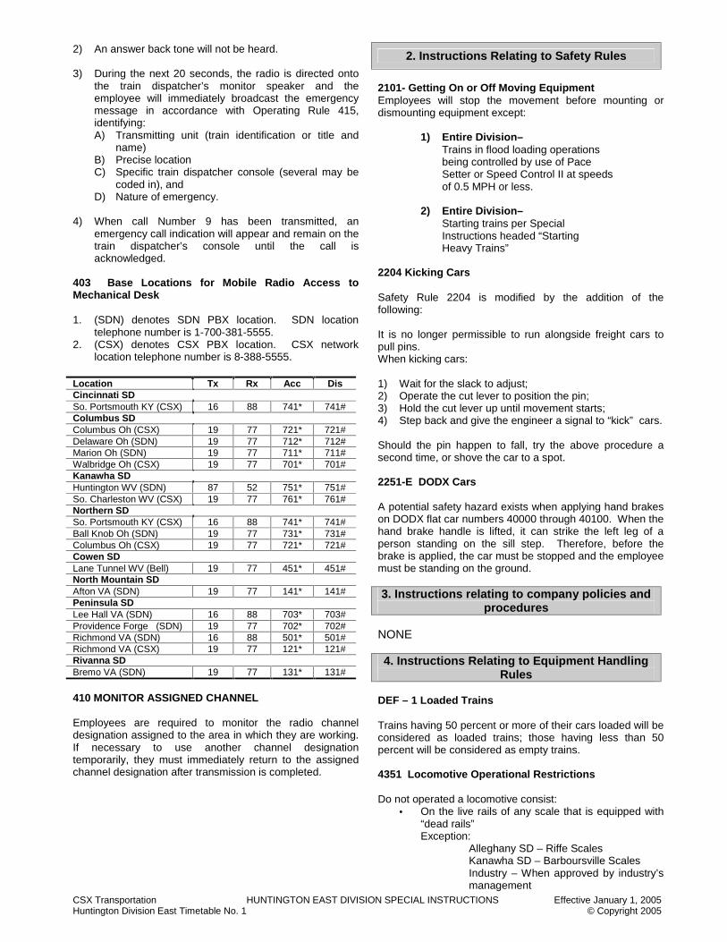
CSX Transportation HUNTINGTON EAST DIVISION SPECIAL INSTRUCTIONS Effective January 1, 2005 Huntington Division East Timetable No. 1 © Copyright 2005
2) An answer back tone will not be heard. 3) During the next 20 seconds, the radio is directed onto
the train dispatcher’s monitor speaker and the employee will immediately broadcast the emergency message in accordance with Operating Rule 415, identifying: A) Transmitting unit (train identification or title and
name) B) Precise location C) Specific train dispatcher console (several may be
coded in), and D) Nature of emergency.
4) When call Number 9 has been transmitted, an emergency call indication will appear and remain on the train dispatcher’s console until the call is acknowledged.
403 Base Locations for Mobile Radio Access to Mechanical Desk 1. (SDN) denotes SDN PBX location. SDN location
telephone number is 1-700-381-5555. 2. (CSX) denotes CSX PBX location. CSX network
location telephone number is 8-388-5555.
Location Tx Rx Acc Dis Cincinnati SD So. Portsmouth KY (CSX) 16 88 741* 741# Columbus SD Columbus Oh (CSX) 19 77 721* 721# Delaware Oh (SDN) 19 77 712* 712# Marion Oh (SDN) 19 77 711* 711# Walbridge Oh (CSX) 19 77 701* 701# Kanawha SD Huntington WV (SDN) 87 52 751* 751# So. Charleston WV (CSX) 19 77 761* 761# Northern SD So. Portsmouth KY (CSX) 16 88 741* 741# Ball Knob Oh (SDN) 19 77 731* 731# Columbus Oh (CSX) 19 77 721* 721# Cowen SD Lane Tunnel WV (Bell) 19 77 451* 451# North Mountain SD Afton VA (SDN) 19 77 141* 141# Peninsula SD Lee Hall VA (SDN) 16 88 703* 703# Providence Forge (SDN) 19 77 702* 702# Richmond VA (SDN) 16 88 501* 501# Richmond VA (CSX) 19 77 121* 121# Rivanna SD Bremo VA (SDN) 19 77 131* 131# 410 MONITOR ASSIGNED CHANNEL Employees are required to monitor the radio channel designation assigned to the area in which they are working. If necessary to use another channel designation temporarily, they must immediately return to the assigned channel designation after transmission is completed.
2. Instructions Relating to Safety Rules
2101- Getting On or Off Moving Equipment Employees will stop the movement before mounting or dismounting equipment except:
1) Entire Division– Trains in flood loading operations being controlled by use of Pace Setter or Speed Control II at speeds of 0.5 MPH or less.
2) Entire Division– Starting trains per Special Instructions headed “Starting Heavy Trains”
2204 Kicking Cars Safety Rule 2204 is modified by the addition of the following: It is no longer permissible to run alongside freight cars to pull pins. When kicking cars: 1) Wait for the slack to adjust; 2) Operate the cut lever to position the pin; 3) Hold the cut lever up until movement starts; 4) Step back and give the engineer a signal to “kick” cars. Should the pin happen to fall, try the above procedure a second time, or shove the car to a spot. 2251-E DODX Cars A potential safety hazard exists when applying hand brakes on DODX flat car numbers 40000 through 40100. When the hand brake handle is lifted, it can strike the left leg of a person standing on the sill step. Therefore, before the brake is applied, the car must be stopped and the employee must be standing on the ground. 3. Instructions relating to company policies and
procedures NONE 4. Instructions Relating to Equipment Handling
Rules DEF – 1 Loaded Trains Trains having 50 percent or more of their cars loaded will be considered as loaded trains; those having less than 50 percent will be considered as empty trains. 4351 Locomotive Operational Restrictions Do not operated a locomotive consist:
• On the live rails of any scale that is equipped with “dead rails” Exception:
Alleghany SD – Riffe Scales Kanawha SD – Barboursville Scales Industry – When approved by industry’s management

CSX Transportation HUNTINGTON EAST DIVISION SPECIAL INSTRUCTIONS Effective January 1, 2005 Huntington Division East Timetable No. 1 © Copyright 2005
• A maximum of eight (8) units may be used in a locomotive consist in multiple control or in tow when operating on a main track, industrial track or industrial spur. Exception: A maximum of 12 units may be used in a locomotive consist in multiple control or in tow when operating on a main track, industrial track or industrial spur on the following Subdivisions and/or locations:
1. Alleghany 2. Bridgeport 3. Cincinnati 4. Columbus 5. James River 6. Kanawha 7. Mountain 8. New River 9. North Mountain 10. Northern 11. Ohio River 12. Peninsula 13. Pickens 14. Piedmont 15. Piney Creek 16. Rivanna 17. Russell 18. Sewell Valley,
Between Meadow Creek and Rainelle 19. Short Line 20. Thomas,
Between BAH 19.5 and BAH 29.0 21. Washington
4406-1 Unit Coal Trains Equipped with Rapid Discharge
Air Dump Systems Unit coal trains equipped with an air dump system for automatic unloading must be operated from the unloading location with the locomotive main reservoir end cock closed and the locomotive-to-auxiliary train line hose removed. This will cause the system to become void of air and therefore eliminate any possibility of these cars dumping enroute. Upon arrival at the location to begin charging the dumping system, the locomotive-to-auxiliary hose must be reapplied and the end cock on the locomotive opened to permit recharging the system for unloading. At the loading facility where these trains have been loaded, they must be inspected to determine: 1) The locomotive-to-auxiliary train line has been
removed, and; 2) All hoses are coupled and angle cocks properly
positioned. If for any reason it becomes necessary to charge the rapid discharge dumping system extreme caution must be used.
3) If these cars are uncoupled and then recoupled at any time, the auxiliary dump hoses must be reconnected.
4406-2 Unit Coal Trains Equipped with Auxiliary Dump Systems The trains listed below are equipped with an air dump system for automatic unloading and must be operated from the indicated unloading location with the locomotive main reservoir end cock closed and the locomotive-to-auxiliary train line hose removed. This will cause the rapid discharge system to become void of air and therefore eliminate any possibility of these cars dumping enroute. Upon arrival at the “location to begin charging dump system” the locomotive-to-auxiliary train line hose must be reapplied and the main reservoir end cock on the locomotive opened to permit charging the system for unloading.
Train Profile Name
Location To Begin Charging Dump System
Unloading Location
U148 to U172 Taft Sanford Orlando
U140 to U147
Lakeland Wildwood Lakeland
U120 to U132 Hague Baldwin Gainesville
N130 to N131
Tampa Electric
Tampa Sutton
N110 to N129
Crystal River Red Level Jct. Crystal River
T140 to T141
Brooksville Tampa Brooksville
N250 to N272 Stilesboro Etowah Cartersville GA
N200 to N240
Harlee Harlee
U250 to U269 Jac Mac
Atlanta Jac Mac
U280 to U288
Pascagoula Mobile Pascagoula
U230 to U232 Gadsden Lagrange Ala Power
West Jeff T818 to T819
Relief Parkersburg Relief, Ohio
Trains handling loaded APEX rapid discharge cars enroute to John Amos Power Plant will couple the locomotive main reservoir hose to the main auxiliary trainline and cut in prior to leaving the loading facility. At the loading facility after the John Amos trains and the trains listed in the table above have been loaded they must be inspected to determine: 1) The locomotive-to-auxiliary trainline has been removed;
and 2) All hoses are coupled and angle cocks properly
positioned. If for any reason it becomes necessary to charge the rapid discharge dumping system extreme caution must be used. Along line of road when making an inspection of the train per Equipment Handling Rule 4300, all rapid discharge hoses must be checked to determine that they are coupled and the angle cocks properly positioned. If the cars are uncoupled and then recoupled, the auxiliary dump hose must be reconnected.
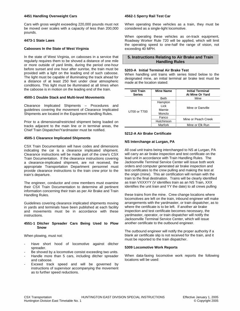
CSX Transportation HUNTINGTON EAST DIVISION SPECIAL INSTRUCTIONS Effective January 1, 2005 Huntington Division East Timetable No. 1 © Copyright 2005
4451 Handling Overweight Cars Cars with gross weight exceeding 220,000 pounds must not be moved over scales with a capacity of less than 200,000 pounds. 4473-1 State Laws Cabooses In the State of West Virginia In the state of West Virginia, on cabooses in a service that regularly requires them to be shoved a distance of one mile or more outside of yard limits, during the period one-hour before sunset and one hour after sunrise, the train must be provided with a light on the leading end of such caboose. The light must be capable of illuminating the track ahead for a distance of at least 250 feet under clear atmospheric conditions. This light must be illuminated at all times when the caboose is in motion on the leading end of the train. 4500-1 Double Stack and Multi-level Movements Clearance Implicated Shipments – Procedures and guidelines covering the movement of Clearance Implicated Shipments are located in the Equipment Handling Rules. Prior to a dimensional/restricted shipment being loaded on tracks adjacent to the main line or in terminal areas, the Chief Train Dispatcher/Yardmaster must be notified. 4505-1 Clearance Implicated Shipments CSX Train Documentation will have codes and dimensions indicating the car is a clearance implicated shipment. Clearance instructions will be made part of the crew’s CSX Train Documentation. If the clearance instructions covering a clearance-implicated shipment, are not received, the appropriate Transportation Department personnel must provide clearance instructions to the train crew prior to the train’s departure. The engineer, conductor and crew members must examine their CSX Train Documentation to determine all pertinent information concerning their train as per Air Brake and Train Handling Rules. Guidelines covering clearance implicated shipments moving in yards and terminals have been published at each facility and movements must be in accordance with these instructions. 4551-1 Ditcher Spreader Cars Being Used to Plow
Snow When plowing, must not: - Have short hood of locomotive against ditcher
spreader. - Be shoved by a locomotive consist exceeding two units. - Handle more than 5 cars, including ditcher spreader
and caboose. - Exceed track speed and will be governed by
instructions of supervisor accompanying the movement as to further speed reductions.
4562-1 Sperry Rail Test Car When operating these vehicles as a train, they must be considered as a single-light locomotive. When operating these vehicles as on-track equipment, Roadway Worker Rule 720 will be applied, which will limit the operating speed to one-half the range of vision, not exceeding 40 MPH.
5. Instructions Relating to Air Brake and Train Handling Rules
5203-A Initial Terminal Air Brake Test When handling unit trains with series listed below to the designated mine, an initial terminal air brake test must be made at the location stated:
Unit Train Series
Mine Name Initial Terminal At Mine Or Yard
Beth Mine Hampton
Lick Marnie Monclo
Mine or Danville
Fanco Hutchinson
Mine or Peach Creek
U700 or T700
Marfork Mine or Elk Run
5212-A Air Brake Certificate NS Interchange at Lurgan, PA All coal unit trains being interchanged to NS at Lurgan, PA will carry an air brake inspection and test certificate on the lead unit in accordance with Train Handling Rules. The Jacksonville Terminal Service Center will issue both work orders and computer generated air brake inspection and test certificates to the crew pulling and making the test at the origin (mine). This air certification will remain with the train to the final destination. Trains will be clearly identified as train VXXXYY (V identifies train as an NS Train, XXX identifies the unit train and YY the date) to all crews pulling these trains from the mine. Crew change locations where locomotives are left on the train, inbound engineer will make arrangements with the yardmaster, or train dispatcher, as to where the certificate is to be left. If another air brake inspection and test certificate becomes necessary, the yardmaster, operator, or train dispatcher will notify the Jacksonville Terminal Service Center, which will issue another certificate to the outbound engineer. The outbound engineer will notify the proper authority if a blank air certificate slip is not received for the train, and it must be reported to the train dispatcher. 5309 Locomotive Work Reports When data-faxing locomotive work reports the following locations will be used:

CSX Transportation HUNTINGTON EAST DIVISION SPECIAL INSTRUCTIONS Effective January 1, 2005 Huntington Division East Timetable No. 1 © Copyright 2005
Lay Up Point Data-Fax Location Data-Fax Number Gladstone Lynchburg Ronceverte Balcony Falls Hinton Quinnimont Rainelle
Clifton Forge 540-863-1487 RNX 8-443-1487
Elk Run Handley Danville Peach Creek So. Charleston Huntington St. Albans
S. Charleston 304-744-3053
Maysville Russell 606-833-7243 RNX 8-434-7243
Chillicothe Columbus 614-445-4226 RNX 8-438-4246
Newport News Williamsburg Newport News 757-380-5009
RNX 8-494-5009 Acca Charlottesville Doswell Verdon
Bryan Park 804-226-7469 RNX 8-442-7469
Cowen Burnsville Rowlesburg WV Central Jct Benwood New Martinsville Parkersburg Ravenswood Pt. Pleasant
Cumberland 301-759-2123 RNX 8-468-2123
Note: The Company line (RNX) must be used instead of the Bell line whenever possible. 5401-1 Locomotive Left Unattended If the temperature is below thirty (30) degrees, employees observing locomotives left unattended and not running will notify the train dispatcher. 5502-1 Tractive Effort – Back up Movements A maximum of 18 powered axles may be used when making back up movements with more than 50 cars. 5502-2 Tractive Effort - s Helper Placement Instructions These Helper Placement Instructions do not apply on the Alleghany, Cowen, James River, Mountain, North Mountain, Peninsula, Piedmont, Rivanna, Thomas and Washington Subdivisions.
Train Makeup Helper Placement
Solid Loaded bulk commodity trains
Westbound - up to 18 axles-on rear.
Eastbound - up to 20 axles on rear.
In excess of the above axles-cut in. (Note)
Train with cars with single axles trucks such as TTFX, TTOX and TTUX and Westbound mixed trains with empty cars in rear 20 cars.
Up to 6 axles-in rear. Up to 12 axles-cut in train or split helper adding one to head end and one to rear trains. (Note)
Solid empty bulk commodity trains, trains without cars with single axle trucks, Eastbound mixed trains with empty cars in rear 20 cars, Westbound mixed trains with rear 20 cars loaded.
Up to 12 axles-on rear.
Exceeding 12 axles-cut in train. (Note)
Note: When cutting in helper in trains, it will be cut in at that point in the train where the tonnage behind the helper would be as close as possible to the tonnage rating of all helper units except the lead unit of the helper. 5553 Stretch Braking 1. To prevent stalling, stretch braking is permitted on
descending grades where running release of train brakes is prohibited.
2. On descending grades, where speed restrictions are in effect requiring a speed of less than 25 MPH, stretch braking will be permitted through the limits of the restrictions.
5551 Starting Heavy Trains When it is necessary to start a heavy train under conditions in which engine wheel slippage may occur, a crew member will dismount from the engine and place him/herself in a position to observe the entire locomotive consist. While the train is being started, the crew member so stationed will be particularly attentive to the possibility of engine wheel slippage; the crew member will arrange to immediately notify the engineer by radio or hand signal if excessive wheel slippage on any of the locomotive units is evident. This is especially crucial while the engines are loading and just before the train is brought into motion. It should be watched, however, until the entire train is underway. Engineers will be on the lookout for a response from the crew member on the ground and will promptly take necessary protection to prevent rail burn. 5555 Setting Off Empty Cars When supplying or setting off empty coal cars, the automatic brake should not be used when the same results can be accomplished by the use of dynamic or independent brake. If the descending grade is to the extent where the dynamic or independent brake is insufficient, the automatic brake may be used in conjunction with the dynamic or independent brake to control movement. After the STOP is made, slack may be bunched by applying sufficient number of hand brakes.
CSX Transportation HUNTINGTON EAST DIVISION SPECIAL INSTRUCTIONS Effective January 1, 2005 Huntington Division East Timetable No. 1 © Copyright 2005
5556 Leaving Equipment Unattended at Newell, PA When trains are left unattended on NS track, the Block Clearance Form must be left on the controlling locomotive. 5556 Leaving Equipment Unattended on the Main Track Before leaving equipment unattended on any main track, the conductor or engineer must convey the following information to the train dispatcher: a) The specific location of head end and rear end (if
known) of train. b) The number of engines on the train, including the lead
engine number. c) The number of cars in the train. d) Any unusual facts about the train, such as oversized
shipments, speed restrictions, and EOT not present or malfunctioning.
When the temperature is 10 degrees or lower, before departing any location with a loaded unit train that has been assembled and tested by a crew other than the road crew assigned to that train, a further air brake test will be made as follows: The road crew taking charge of the train will make an additional inspection of the air brakes to determine that all brakes apply and release on each car from a 20 pound brake pipe reduction. Exception: The following trains are exempt from this inspection;
1. Trains operating between Huntington and Benwood in Huntington and Parkersburg, WV.
2. Westward trains making their initial movement from Grafton, WV.
3. Eastward trains making their initial movement from Burnsville, Wv.
5559-1 Recharging after an Undesired Emergency Application Following an undesired application of the automatic brake system on grades of 1% or greater, a minimum of 20 minutes charging time of the brake system is required. During cold or inclement weather, additional charging time may be required. 5600-1 Instructions for Installing and Operating Helper Link Equipment 1. Description of equipment:
Helper-Link equipment is designed to permit helper locomotives to be attached and detached from road trains without making brake pipe hose connections between the rear car and the helper consist. This will enable the helper consist to detach from the train while still moving. For this to be possible, two pieces of equipment must be used. The first piece of equipment, a Helper-Link box, is to be mounted on the helper locomotive on the end to be coupled to the road train. The second piece of equipment, a two-way rear-end telemetry device, is mounted on the rear car, thereby establishing a complete two-way telemetry system. This two-way system enables the locomotive engineer
to initiate an emergency brake application beginning at the rear car by properly positioning an emergency command switch found on a two-way head of train device (HTD2) on the controlling locomotive when equipped, but also permits Helper-Link equipment to transmit emergency signals to the rear car.
2. Installation of Equipment:
The two-way end of train device attaches to casting holes in the side of the drawhead of the rear car in a similar manner as previous CSXT end-of-train devices (EOT). Once attached, the air hose of the two-way device must be connected to the brake-pipe hose on the rear car and the angle cock opened. At the time of the initial installation, a test for accuracy and continuity must be performed as per Air Brake and Train Handling Rules. The Helper-Link box attaches to the helper locomotive end being coupled to the rear car of the train. The box is held in place by small chains placed around upright handrail stanchions. This box incorporates three hoses. The first hose, marked “Main Reservoir,” must be coupled to the main reservoir equalizing hose on the locomotive and the end cock opened. The second hose, marked “Brake Pipe,” will be coupled to the brake-pipe hose on the helper locomotive and the angle cock opened. The third hose is permanently connected to the pin-lift mechanism, but must also be coupled to the Helper-Link box during installation. The helper locomotive jumper cable must now be inserted into the Helper-Link box receptacle. The Helper-Link box also incorporates a coupler-lift mechanism. The pin-lift mechanism mounts under the walkway and above the drawbar, held in place by two clamps that attach to the underside of the walkway. The mechanism has a lifting hook that must be attached to the coupler-pin lift loop on the locomotive coupler. A visual check must be made to ensure that all hoses and jumper cables will not interfere with the operation of the lift chain, which has been connected to the coupler. Once installed, the Helper-Link equipment must be tested as follows:
1) The knuckle must be closed on the locomotive end with the Helper-Link box.
2) The trainline power-reduction rheostat knob on the helper locomotive must be positioned to full power.
3) Engine Run, Generator Field and Control Fuel Pump must be closed.
4) Reverser must be in FWD/REV. 5) Position the power reduction toggle switch to “Trainline
Power Reduction” (all units). 6) Inspection must be made to determine that the knuckle
has been operated by the coupler-lift mechanism. 7) If the coupler pin has lifted, the equipment is ready for
use, and if not, re-check the main reservoir equalizing the end cock and jumper cable connection from the helper locomotive to the Helper-Link box and re-try Steps 2 through 4.
8) Turn the trainline power reduction switch to the “Off” position.
3. Operation of Equipment Before attaching to the rear of the train, the engineer will make a Safety STOP, and then ascertain that the knuckle on the helper locomotive is open on the end to be attached to the train. After coupling to the rear of the train, stretch

CSX Transportation HUNTINGTON EAST DIVISION SPECIAL INSTRUCTIONS Effective January 1, 2005 Huntington Division East Timetable No. 1 © Copyright 2005
slack to insure that the coupling has been made and position the helper locomotive brake equipment per Air Brake and Train Handling Rules. The helper engineer will then make a visual inspection from the walkway of the helper locomotive to see the telemetry device is still in place and none of the hoses will be affected by the coupler once movement begins. The helper engineer will open the Helper-Link box lid and perform the following start-up tasks: (1) Thumbwheel switch assembly numbers must be the
same as the ID code number on the end-of-train device.
(2) Check the communication between the Helper-Link and rear-of-train telemetry device by pressing the Com/Check (communications check) pushbutton. The alphanumeric display will say “Com OK.” If the display shows “No Com,” this indicates the Helper-Link is not communicating with the rear device. If this occurs, the brake pipe hose of the rear car will be coupled to the helper locomotive brake pipe hose of the rear car and both angle cocks will be opened. The brake test and train operation will be performed in the conventional manner, as if the Helper-Link equipment was not on helper.
(3) Start the electronic signal by pressing the “Enable” button.
Note: At this time, the Helper-Link’s “Enable” light is illuminated indicating the electronic signal is connected. This connection establishes the signal that will maintain the helper locomotive’s brake pipe pressure at the same level as brake pipe pressure at the rear of train.
(4) Close Helper-Link box Lid. Upon returning to the operating cab of the helper locomotive, the helper engineer will observe brake pipe pressure and notify the engineer on the lead locomotive consist when the helper is ready for a helper service brake test. Brakes should apply and release on the helper locomotive as if brake pipe air hoses were coupled between the helper locomotive and the rear car. When the brake test is completed, the train is ready to proceed. Note: During train movement, if it is necessary for the helper locomotive engineer to initiate an emergency brake application, the automatic brake must be placed in “Emergency” position on the helper locomotive. The Helper-Link will transmit an emergency brake application request via electronic signal to the two-way device located within the EOT. Similarly, the lead engineer, when making a service or emergency brake reduction, will cause the two-way EOT to transmit the drop in brake pipe pressure to the Helper-Link, thereby causing the helper brakes to apply. When approaching the location where the helper is to detach, it will not be necessary to STOP the train to cut off the helper locomotive. The helper engineer, when approaching the cut-off location, will turn the power reduction knob to full power and position the toggle switch to “Trainline Power Reduction.” This will activate the pin-puller, lifting the helper locomotive coupler pin. Once the signal is received in the Helper-Link box to lift the pin, 130 - 140 PSI air pressure will be forced into the pin puller air line to activate it. At that point, the helper engineer will receive an audible alarm bell signal on the locomotive.
When that signal is received, while still moving and before reducing throttle, the helper engineer will place automatic brake valve handle to “Release,” and cut in the brake valve cutout valve. The engineer will gradually reduce power allowing ample time between throttle changes to allow slack to stretch. As the rear car separates, a STOP will be made by gradually applying the independent brake. Note: No emergency brake application will take place from the separation of equipment. Control independent brake cylinder pressure to prevent sliding of locomotive wheels as the locomotive separates from the train. 4. Engineer alarm feature: Once the Helper-Link has established communication with the two-way EOT on the rear of the train, if the EOT or Helper-Link box malfunction, the alarm bell will ring in the helper locomotive cab indicating a problem. If this occurs and trouble cannot be corrected, the train will be stopped and the brake pipe hose connected for conventional operation. 5655-1 Special Instructions for Snow Accumulation in excess of 24 Inches During periods of snowfall accumulation in excess of 24 inches, track where heavy descending grades are three miles or longer, and 1.5% or greater, should be plowed with a spreader or other plow when possible. Snowplows on locomotives should only be used as a last resort, as they do not move snow away from track structure sufficiently to protect freight car braking systems. This plowing should be done at least ten miles prior to and include the heavy descending grade when possible. This is done ahead of the grade in order that the brake system can be warmed by a train brake application without re-icing prior to grade descent. When snow accumulations have exceeded 24 inches, no trains, except light engines may descend these grades until the following: a) The grade and track 5 miles preceding the grade have
been traversed not more than 1 hour previous to additional train movements, or
b) It has been determined that roadbed snow level does not exceed 24 inches.
Grades Subject to Snow Plowing Subdivision Location Cowen SD BUC 116.5 to BUC 96.0 Mountain SD BA 269.0 to BA 242.0
BA 223.0 to BA 207.0 Thomas SD BA H69.0 and BA H29.0
G&E CAJ 2.0 and CAJ 6.0 CAJ 10.5 and CAJ 13.8
Island Creek CMC 3.6 and CMC 10.6 Norfolk Southern Winding Gulf Spur 17.0 and 21.0
Piney Creek CAN 2.0 and CAN 24.0 Raleigh SW & Winding Gulf CAQ 7.0 and CAQ 16.0
Sewell Valley CAF 0.5 and CAF 14.8 CAF 3.0 and CAF 34.5
Pine Creek CMF 3.0 and CMF 6.0
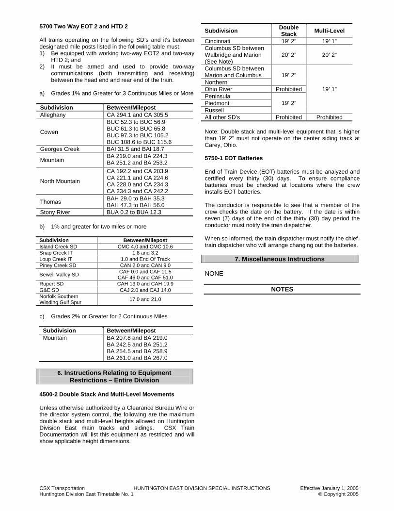
CSX Transportation HUNTINGTON EAST DIVISION SPECIAL INSTRUCTIONS Effective January 1, 2005 Huntington Division East Timetable No. 1 © Copyright 2005
5700 Two Way EOT 2 and HTD 2 All trains operating on the following SD’s and it's between designated mile posts listed in the following table must: 1) Be equipped with working two-way EOT2 and two-way
HTD 2; and 2) It must be armed and used to provide two-way
communications (both transmitting and receiving) between the head end and rear end of the train.
a) Grades 1% and Greater for 3 Continuous Miles or More Subdivision Between/Milepost Alleghany CA 294.1 and CA 305.5
Cowen
BUC 52.3 to BUC 56.9 BUC 61.3 to BUC 65.8 BUC 97.3 to BUC 105.2 BUC 108.6 to BUC 115.6
Georges Creek BAI 31.5 and BAI 18.7
Mountain BA 219.0 and BA 224.3 BA 251.2 and BA 253.2
North Mountain
CA 192.2 and CA 203.9 CA 221.1 and CA 224.6 CA 228.0 and CA 234.3 CA 234.3 and CA 242.2
Thomas BAH 29.0 to BAH 35.3 BAH 47.3 to BAH 56.0
Stony River BUA 0.2 to BUA 12.3 b) 1% and greater for two miles or more Subdivision Between/Milepost Island Creek SD CMC 4.0 and CMC 10.6 Snap Creek IT 1.8 and 3.2 Loup Creek IT 1.0 and End Of Track Piney Creek SD CAN 2.0 and CAN 9.0
Sewell Valley SD CAF 0.0 and CAF 11.5 CAF 46.0 and CAF 51.0
Rupert SD CAH 13.0 and CAH 19.9 G&E SD CAJ 2.0 and CAJ 14.0 Norfolk Southern Winding Gulf Spur
17.0 and 21.0
c) Grades 2% or Greater for 2 Continuous Miles
Subdivision Between/Milepost Mountain BA 207.8 and BA 219.0
BA 242.5 and BA 251.2 BA 254.5 and BA 258.9 BA 261.0 and BA 267.0
6. Instructions Relating to Equipment
Restrictions – Entire Division 4500-2 Double Stack And Multi-Level Movements Unless otherwise authorized by a Clearance Bureau Wire or the director system control, the following are the maximum double stack and multi-level heights allowed on Huntington Division East main tracks and sidings. CSX Train Documentation will list this equipment as restricted and will show applicable height dimensions.
Subdivision Double Stack Multi-Level
Cincinnati 19’ 2” 19’ 1” Columbus SD between Walbridge and Marion (See Note)
20’ 2” 20’ 2”
Columbus SD between Marion and Columbus Northern
19’ 2”
Ohio River Prohibited Peninsula Piedmont Russell
19’ 2”
19’ 1”
All other SD’s Prohibited Prohibited Note: Double stack and multi-level equipment that is higher than 19’ 2” must not operate on the center siding track at Carey, Ohio. 5750-1 EOT Batteries End of Train Device (EOT) batteries must be analyzed and certified every thirty (30) days. To ensure compliance batteries must be checked at locations where the crew installs EOT batteries. The conductor is responsible to see that a member of the crew checks the date on the battery. If the date is within seven (7) days of the end of the thirty (30) day period the conductor must notify the train dispatcher. When so informed, the train dispatcher must notify the chief train dispatcher who will arrange changing out the batteries.
7. Miscellaneous Instructions NONE
NOTES

CSX Transportation HUNTINGTON EAST DIVISION SPECIAL INSTRUCTIONS Effective January 1, 2005 Huntington Division East Timetable No. 1 © Copyright 2005
NOTES
NOTES

CSX Transportation HUNTINGTON EAST DIVISION SPECIAL INSTRUCTIONS Effective January 1, 2005 Huntington Division East Timetable No. 1 © Copyright 2005
SPEED TABLE Time Per Mile
Time Per Mile
Time Per Mile
Min. Sec
Mile Per
Hour Min. Sec
Mile Per
Hour Min. Sec
Mile Per
Hour
0 45 80.00 1 32 39.13 2 19 25.90
0 46 78.26 1 33 38.71 2 20 25.71
0 47 76.59 1 34 38.29 2 21 25.53
0 48 75.00 1 35 37.89 2 22 25.35
0 49 73.47 1 36 37.50 2 23 25.17
0 50 72.00 1 37 37.11 2 24 25.00
0 51 70.59 1 38 36.73 2 25 24.83
0 52 69.23 1 39 36.36 2 26 24.66
0 53 67.92 1 40 36.00 2 27 24.49
0 54 66.66 1 41 35.64 2 28 24.32
0 55 65.45 1 42 35.29 2 29 24.16
0 56 64.28 1 43 34.95 2 30 24.00
0 57 63.16 1 44 34.61 2 31 23.84
0 58 62.07 1 45 34.29 2 32 23.68
0 59 61.02 1 46 33.96 2 33 23.53
1 00 60.00 1 47 33.64 2 34 23.38
1 01 59.02 1 48 33.33 2 35 23.23
1 02 58.06 1 49 33.03 2 36 23.08
1 03 57.14 1 50 32.73 2 37 22.93
1 04 56.25 1 51 32.43 2 38 22.78
1 05 55.38 1 52 32.14 2 39 22.64
1 06 54.54 1 53 31.86 2 40 22.50
1 07 53.73 1 54 31.58 2 41 22.36
1 08 52.94 1 55 31.30 2 42 22.22
1 09 52.18 1 56 31.03 2 43 22.08
1 10 51.43 1 57 30.77 2 44 21.95
1 11 50.70 1 58 30.51 2 45 21.82
1 12 50.00 1 59 30.25 2 46 21.69
1 13 49.31 2 00 30.00 2 47 21.56
1 14 48.65 2 01 29.75 2 48 21.43
1 15 48.00 2 02 29.51 2 49 21.30
1 16 47.37 2 03 29.27 2 50 21.18
1 17 46.75 2 04 29.03 2 51 21.05
1 18 46.15 2 05 28.80 2 52 20.93
1 19 45.45 2 06 28.57 2 53 20.81
1 20 45.00 2 07 28.34 2 54 20.70
1 21 44.44 2 08 28.12 2 55 20.58
1 22 43.90 2 09 27.91 2 56 20.45
1 23 43.37 2 10 27.69 2 57 20.34
1 24 42.86 2 11 27.48 2 58 20.22
1 25 42.35 2 12 27.27 2 59 20.11
1 26 41.86 2 13 27.07 3 00 20.00
1 27 41.38 2 14 26.87 4 00 15.00
1 28 40.91 2 15 26.66 6 00 10.00
1 29 40.45 2 16 26.47 12 00 5.00
1 30 40.00 2 17 26.28
1 31 39.56 2 18 26.09