human factors in design of control rooms for …€¦ · che 597: process safety management &...
TRANSCRIPT

CHE 597: Process Safety Management & Analysis
Human Factors in Design of Control Rooms
for Process Industries
Ravi Joshi and Ben Daum
December 4th, 2017

2
1. Executive Summary
Control rooms are essentially complex sociotechnical systems involving significant levels
of computer-plant, human-computer, and human-human interactions. Control rooms handle a
variety of activities ranging from general information retrieval, normal operation, optimization and
abnormal situation handling. The operators in control rooms often work for long hours handling
extremely demanding tasks and are responsible for safe and efficient operation of processes.
Many control rooms in operation today and which were built in the 1980-90s have evolved
from being large control panels and thus their design has been focused on convenience of installing
the technical equipment, rather than the well-being of the operators. The operators in these control
rooms must deal with poor ambient conditions leading to sick-building syndrome, crammed
technical upgrades to old SCADA systems, confusion caused by relevant and irrelevant alarms,
and several sources of distraction.
An “operator-first” approach towards the design of control rooms has been adopted by
human factors and ergonomics literature and by several industrial standards (ISO 11064, EEMUA
201, etc.), wherein the design of control room elements and architecture unfolds from within, with
the operator being the starting point. The detailed design phase in this approach provides
engineering design principles for the workstation, displays, alarm systems, environmental factors
(temperature, air quality, acoustics, vibration, lighting and aesthetics) and the layout. Effort has
been made within these design principles to closely correlate the objectively measured variables
with the subjective experiences of the operators.
In addition, few learnings from the aviation and nuclear industry can also be supplemented
to these design principles. In air traffic control rooms, the noise from plastic flight strips serves as
an alert signal and the operators follow specific guidelines to exchange messages with the pilots.
These learnings can be utilized in process industries to enhance the co-ordination among operators
working jointly and promote effective communication between operators and on-field workers.
Also, in nuclear industry specific guidelines are in place for the operators to handle events during
abnormal operations and control room system is modeled as one single cognitive system.
Similarly, in process industries the operator effectiveness can be enhanced during abnormal
operations and the human factors can be best addressed by considering the control room system
along with the operators, as a single cognitive system.

3
2. Contents
Table of Contents
1. Executive Summary .................................................................................................................... 2
2. Contents ...................................................................................................................................... 3
3. Introduction ................................................................................................................................. 5
4. Literature Review........................................................................................................................ 7
5. Objective ..................................................................................................................................... 8
6. Important Issues .......................................................................................................................... 8
6.1. Poor design of existing control room spaces ....................................................................... 8
6.2. Design principles for environmental factors within control rooms ..................................... 9
6.3. Effect of situations or disturbances on operator performance ............................................. 9
6.4. Communication from control room to field workers ........................................................... 9
6.5. Issues with existing alarm system design ............................................................................ 9
6.6. Ambient conditions ............................................................................................................ 10
7. Analysis..................................................................................................................................... 10
7.1. Inadequacies of existing control room design ................................................................... 10
7.2. Existing design principles to enhance human performance in control rooms ................... 13
7.3. Design principles for future control rooms ........................................................................ 25
8. Conclusions ............................................................................................................................... 28
9. References ................................................................................................................................. 30

4
List of Figures
Figure 1. First generation control room layout ............................................................................. 11
Figure 2. Phases involved in design of control centers with a human factors (HF) approach ...... 14
Figure 3. Variation of predicted mean vote (PMV) with the predicted percentage of thermally
dissatisfied people (PPD) .............................................................................................................. 21
Figure 4. Cognitive model connecting the themes identified for safe operation of nuclear power
plant control rooms ....................................................................................................................... 28
List of Tables
Table 1. EEMUA 991:2007 – Guidelines for acceptable alarm rate ............................................ 19
Table 2. ISO 11064-6:2005 – Minimum requirements for ambient temperature ......................... 20
Table 3. ISO 11064-6:2005 – Minimum requirements of for control room lighting .................. 22
Table 4. ISO 11064-6:2005 – Requirements for air quality ......................................................... 22
Table 5. Minimum requirements for noise levels as per ISO 11064-6:2005 ................................ 23
Table 6. ISO 11064-6:2005 – Minimum requirements for reflecting surfaces ............................. 24

5
3. Introduction
Control rooms serve as the central point of operations and production, and thus are critical
for companies to make or lose money. Controls rooms are also critical as they identify catastrophic
incidents early and provide an opportunity for their mitigation. The control room operators often
work for long hours in front of computer screens to ensure safe and efficient operations 24/7. Most
control rooms currently in operation have been designed in the 1980-90s, in which the decisions
regarding the design of the space was based on convenience of installing the technical equipment
rather than on the operator’s needs. The operators and owners have suffered the consequences with
injuries, eye strain, repetitive motion impairment and slow response time to abnormal events [1].
Numerous activities take place in a control room, but each activity can be placed into one
of four categories: abnormal situation handling, normal operation, optimization, and general
information retrieval [2]. Abnormal situation handling concerns any events in the plant outside of
normal operations such as failures in processes, startup, and shutdown. It is during these abnormal
situations where the control room operator must be most alert to be able to efficiently process
information and make sound decisions. Abnormal situations are typically brought to the attention
of the control room operator through visual or auditory alarms, which must be recognized and
understood by the operator. Normal operations include events which are standard procedures
within plant operations. Due to these processes typically being automated, the operator is free to
make fewer decisions during normal operations, he/she must remain alert and work efficiently [2].
The downtime obtained during normal operations allows for system optimization, in which the
current system is analyzed, and considerations are made to improve the performance of the plant.
The final category, general information retrieval, may be automated through an information
technology system. [2]
When designing the control room or rooms for a plant, there exist two possibilities:
distributing smaller control rooms specific for operations throughout the plant, and designing a
larger, single, centralized control room for all the operations within the plant [3]. The number of
advantages and disadvantages of a centralized control facility make this decision somewhat
complicated. Centralized control rooms allow for reduced redundancy of control equipment, thus
lower costs, as multiple processes can be controlled by equipment [3]. Distributing control rooms
throughout the plant often results in placing the control room very close in proximity to the

6
processes which they control. This proximity is inherently dangerous for the operators, as any
catastrophic event during a process puts them at risk. A centralized facility can be placed at a
farther distance from processes, increasing the safety of the personnel within the facility. However,
increasing distance between processes and controls decreases communication between control
room operators and field operators. Face-to-face communication is replaced with communication
through radio when a centralized control facility, which can lead to inefficient communication and
accidents. When choosing between a centralized facility and distributed control rooms, careful
evaluation of the cost and benefits of each option must be considered [3]. In either scenario,
however, the control room or facility must be carefully designed to include ergonomics to limit
the number of accidents caused by human error.
No matter whether a plant utilizes a centralized control room or numerous dedicated control
stations, effective communication between field workers and control room operators is required
for safe operations. Taking the air traffic control industry as an example, air traffic controllers must
communicate information to pilots, which must read the message back to indicate comprehension
of the message. The industry has determined that long, complex messages cause confusion in the
pilots, and readback errors occur [4]. In the chemical industry, increasing distances between the
control room and the respective processes requires radio communication between operators and
field workers. To maintain safe processes, the messages sent to and from the control room must
be able to be received accurately by the field worker. Despite the findings in the air traffic control
industry, readback messages are not used in the chemical industry, and effective communication
may be limited.
The incident at Three Mile Island has garnished attention for the use of human factors in
the design process of control rooms for nuclear power plants. Though the accident was caused by
mechanical failure, the issue was compounded by actions in the control room. Due to a lack of
human factors, the system’s control room at Three Mile Island had confusing user interfaces and
unclear indicators [5]. This lack of human factor considerations allowed the control room operator
to believe that too much coolant was in the reactor, rather than too little. If human factors were
employed in the design of the control room, the operator could have responded more accurately to
the problem. The nuclear industry also considers a number of additional aspects to be important in
a control room [6]. The behavior, abilities and management of control room staff through

7
established rules is an additional aspect to be considered. A set of rules which clearly states the
role of each member of the team as well as a defined set of behaviors for people in the control
room to limit distractions of the team.
4. Literature Review
Human Factors in the Design and Evaluation of Central Control Room Operations [2]
This textbook covers the concepts of human factors (ergonomics) and how they can be
implemented in the design of new control rooms. It focuses on control room layout, environment,
alarms, and supervisory control and data acquisition (SCADA) systems. Several standards from
the International Standard Organization (ISO) and the Engineering Equipment and Materials Users
Associations (EEMUA) are summarized, including:
ISO 11064-1: Principles for the design of control centers
ISO 11064-2: Principles for the arrangement of control suites
ISO 11064-3: Control room layout
ISO 11064-4: Layout and dimensions of workstations
ISO 11064-5: Displays and controls
ISO 11064-6: Environmental requirements for control centers
ISO 11064-7: Principles for the evaluation of control centers
ISO 9241-5: Ergonomic requirements for office work with visual displays terminals
(VDTs), Part 5: workstation layout and postural requirements
EEMUA 991: Alarm systems - a guide to design, management and procurement
EEMUA 201: Process plant control desks utilizing human-computer interfaces: a guide to
design, operational and human-computer interface issues
Aspects of nuclear power plant control room system [6]
A number of aspects contributing to safe operation of nuclear power plant control rooms
are identified and categorized in six overall themes: situations, functions, tasks, structural
elements, and characteristics.

8
Influence of ATC message length and timing on pilot communication [7]
This report discusses the results of subjecting pilots to a simulation in which air traffic
controllers provided information with varying levels of complexity and length. It was determined
that readback errors and requests to repeat messages increased with increasing complexity of
messages.
Computation & effects of ATC message complexity & length on pilot readback performance [4]
This article confirms the analysis that increased complexity and length of messages
increases the number of readback errors. In addition, it was determined that pilots had more
difficulty in processing air traffic control messages when on approach as compared to departure.
Moreover, it was determined that longer messages did not affect pilot performance on departure,
but caused readback errors upon approach.
Effective control center design for a better operating environment [3]
This article compares the perceived benefits and limitations of centralized control centers
versus numerous dedicated control rooms. It also discusses guidelines on how a chemical plant
should choose between the two options when designing a control room.
5. Objective
To identify the deficiencies in design and ergonomics of existing control rooms, summarize
existing standards and best practices for improving human performance in control rooms, and
utilize learnings from nuclear and aviation industry to supplement future design of control rooms.
6. Important Issues
6.1. Poor design of existing control room spaces
Many control rooms in operation today were designed in 1980s or 1990s, and were small,
poorly lit rooms with a large control panel which was hardwired to the process which it monitored.
Furthermore, consoles were designed by instrumentation engineers without the knowledge of
human factors. Technical upgrades are often crammed into these old designed spaces. Thus,

9
operators are compelled to adjust with the newer technology in a space not ergonomically designed
for its use. Separate areas such as kitchens or meeting rooms were never implemented into the
design of these spaces, and numerous distractions occur as a result.
6.2. Design principles for environmental factors within control rooms
The design for environmental parameters such as temperature, lighting, air quality, noise,
vibration and aesthetics is challenging because the human mechanisms to sense these
environmental parameters are much different than the instruments used to measure them. This
leads to a situation, where the objectively measured states are different than the subjectively felt
states by the operators.
6.3. Effect of situations or disturbances on operator performance
The current design standards address the quality of physical environment within the control
rooms, however, they do not account for factors affecting the mental environment of the operators.
External disturbances from visitors and events/situations during start-up, shutdown or outage have
been shown to impact operator performance in nuclear industry.
6.4. Communication from control room to field workers
The separation of control room operators and on-field operators causes issues with
communication. The aviation industry has determined that message complexity results in an
increased likelihood for readback errors from the pilot to the air traffic controller [4,7].
6.5. Issues with existing alarm system design
Survey of existing independent control consoles in petrochemical industry has shown an
excessive alarm rate (more than 10 alarms in a 10-minute period) than the operators can handle.
Also, exposure to spurious alarms increases the probability of operators disregarding actual alarms.
Moreover, similar sounding alarms from neighboring consoles can cause confusion and distraction
for control room operators.

10
6.6. Ambient conditions
Poor ambient conditions such as lighting, temperature, and poor air quality can cause
physical and mental stress for control room operators. Specifically, poor air quality has been linked
to long term problems of “sick-building” syndrome and feeling of malaise and lethargy for control
room operators [2]. The increased stress and feeling of lethargy can cause operators to be
overwhelmed and make mistakes.
7. Analysis
7.1. Inadequacies of existing control room design
The root cause of the issues within existing control rooms is that they have evolved from
large control panels which were originally designed by instrumentation engineers without the
considerations of human factors (ergonomics) [8]. The spaces which housed these large control
panels were originally designed by taking into consideration the needs of the instrumentation,
while forgoing the comfort of the operators. The resulting control rooms tended to be long, narrow,
poorly-lit rooms filled with large control panels preventing logical flow of traffic (Figure 1) [8].
In addition, auxiliary facilities such as restrooms and kitchens were not implemented into the
design of these buildings. Operators working in these rooms for extended periods of time
experienced headaches, eye-strain, and poor sleeping patterns – all of which may yield poor work
and mistakes. One survey of a control room found that more than half of the operators reported
sore throats and congested noses [2]. The same survey revealed that half of the operators reported
sore eyes, mental fatigue, headaches, and tiredness [2]. Upgrades and additions to the control
rooms resulted in extremely crowded spaces which provide distractions from operator
communication and alarms [9].

11
Figure 1. First generation control room layout [8]
7.1.1. Supervisory Control and Data Acquisition (SCADA)
The Supervisory Control and Data Acquisition (SCADA) system is the method by which
information is transferred from sensors within the plant to the operators who are managing the
processes. The SCADA system also allows for the operator to physically interact with the
components of a process [2]. Before the invention of the microchip, the early SCADA systems
were large display consoles which were hardwired to the components which they managed [2].
Their size and inconvenient wiring made it difficult to move the system when upgrades or
replacements were installed, thus the origin of the cramped control room, as discussed previously.
Digitization of these large systems allowed for numerous operations to be remotely controlled
through a single computer source, and often with the help of automation [8]. However, the
introduction of automation has changed the workload of the operator to be more focused on
optimization of the process, thus skills involving physical controls are utilized only when
automation fails or is otherwise unable to perform the task at hand [2]. Updating the SCADA
system from the previously used hardwired systems to a single workspace is not an easy task.

12
7.1.2. Distractions from alarms
Within the SCADA system, alarms are used to notify an operator about the status of a
system. They first bring to the attention of an operator that a system is not functioning properly,
then provide information that will allow the operator to return the system to normal function. The
alarm may be visual, by means of a computer screen popup, or an auditory sound which indicates
an issue. In the early days of control rooms, in which space was limited, it was difficult to
distinguish between alarms. An auditory alarm at one workstation could be heard at a nearby
workstation, confusing the operator and eventually training the operator to ignore the alarm sound
altogether [9].
In addition to alarms during abnormal conditions, some alarms, known as standing alarms,
exist during normal operations. While the EEMUA guide recommends there to be no more than
one alarm every ten minutes, a survey of 37 control stations determined that two thirds of consoles
exceeded this limit [2]. Furthermore, only two out of 37 consoles came close to a target of less
than 10 alarms in 10 minutes after an upset [2]. Depending on the system being monitored, an
operator could be monitoring up to 800 pages of information and 20,000 alarms [2]. The frequency
of alarms, and the uniformity of alarm sound for different situations, could be heard throughout
the control room due to the small size of the room relative to the number of operators in the room.
7.1.3. Noise distractions
Alarms are not the only sounds which can be sources of distraction for a control room
operator. In daily activity within the control room, numerous other sounds, such as fans,
computers, and conversations can cause distractions for the operators within the control room. The
tight spaces in which early control rooms were built force many large consoles to be placed near
one another [9]. Noises from a neighboring console, such as face-to-face meetings or music can
cause distractions for the control operator. The first-generation control rooms were not designed
to include conference rooms or otherwise separate areas away from the consoles in the control
center, so any conversations or meetings may be heard by anyone in the room [9].
7.1.4. Ambient conditions
The ambient conditions within a control room can strongly affect the performance of the
operators. Aspects such as poor lighting, bad air quality, and uncomfortable temperatures can

13
cause unnecessary stresses for the operators or even cause physical injuries such as headaches
which cause poor performance of an operator.
The first-generation control rooms were not designed to be as cramped as they would
eventually become, thus the lighting was never designed for these spaces. Furthermore, even
lighting in modern control rooms is designed when the room is empty, rather than filled with
furniture, equipment, and people [9]. The resulting bad lighting within control rooms can cause
headaches and eye strain which distract the operator.
In the early design of control rooms, air flow inside the cramped spaces was very poor,
thus sick building syndrome was a concern. Modern-day control rooms are designed with air
conditioning which allows for control of temperatures as well as air quality. This luxury was not
as readily accessible in the early design of control rooms. Poor indoor air quality can lead to “sick-
building” syndrome in control room operators. Sick-building syndrome can cause workers to
display symptoms such as eye, nose, and throat irritation, nausea, dizziness, and mental fatigue
[10].
7.2. Existing design principles to enhance human performance in control rooms
Stanton and others have put together the phases involved in a human factor approach to
design of control centers by combining the guidelines of ISO 11064-1:2001 and the work by Green
and Collier [11]. The phases involved in the process are shown in Figure 2. This paper is focused
on Phase D which involves detailed design of the control room elements.

14
Figure 2. Phases involved in design of control centers with a human factors (HF) approach
[2,11]
A number of current standards provide engineering principles for detailed design of control
room elements. The following standards are covered for this paper –
Workstation design – ISO 11064-4, ISO 9241-5
Display design – EEMUA 201
Alarm system design – EEMUA 191

15
Environmental factors – ISO 11064-6
Layout design – ISO 11064-2, ISO 11064-3
7.2.1. Workstation design
The design of the actual workstation within a control room involves consideration for the
biometrics and anthropometrics of the operator population and the movements involved in the
tasks to be performed. Standards such as ISO 11064-4:2004, ISO 9241-5:1999 provide detailed
guidelines for the layout and dimensions of the workstation. The operator is required to have access
to three points when using the workstation, the floor, the chair and the desk surface and keyboard
[2]. The design of the workstation is recommended to fit from 5th to 95th percentile of the
population under consideration. The dimensions to fit within this percentile range are usually
determined for one class of population (genetic origin, nationality, ethnic background, etc.), and
therefore the design of workstations for an international workforce should be carried out with extra
precaution [2].
For seat design, the important dimensions to be considered are the seat height, depth, width
and lateral clearance between the armrests. For desk design, it is recommended to have a flexible
arrangement for the screen, keyboard, documents and related documents to minimize the need of
uncomfortable head and eye movements. The desk height need not be flexible, as the sitting height
can be adjusted by adjusting the seat height and the floor height can be manipulated by providing
a footrest. The legroom height is determined from the legroom depth from the front edge of the
desk, and the guidelines are provided by ISO 9241-5:1999. Additionally, the surface of the desk
is recommended to be a low reflectance surface.
7.2.2. Display design
Displays are important components of the Supervisory Control and Data Acquisition
(SCADA) systems. Current SCADA systems employ automation and digitalization and thus are
able to detect changes in process variables, apply built in optimization rules and perform
manipulation of physical components at a much faster rate than the operators themselves can.

16
Display characteristics: Ravden and Johnson [12] studied human factors involvement in
human-computer (HCI) interaction and the following parameters can be considered for display
design based on their usability criteria –
Visual clarity – The displays should provide high visual clarity making the content clear,
organized, unambiguous and easy to read.
Consistency – The way the system looks, and works should be consistent with the user
conventions and expectations.
Explicitness – The structure of the system and the way it works should be clear to the
operator
Appropriate functionality – The system should meet the needs and requirements of the
operators and shouldn’t require the operators to use external tools (calculators, etc.) for
carrying out normal operations
Information feedback – The operators should be able to receive a feedback such as if their
actions have been successful or not, and what could be the next possible steps in case of
unsuccessful actions.
Error prevention & control – The system should be designed to eliminate the possibility of
human error, with built-in functions to check user inputs for errors or inputs leading to
potential error situations, before the input is processed.
User guidance & support – The user, operations and maintenance manuals should be easy
to follow and should be provided both in software form and in document form. An on-line
help facility from the system administrator will be a plus.
The standard EEMUA 201:2002 evaluates information density as the quantity of visible
node instances containing the information on the screen per screen space area of the entire interface
in pixels. The standard recommends the packing density to be around 25-30% with the upper limit
being 50%.
Display size: The size of display screens should be decided based on the category of task
being performed. Tasks which involve changing spatial orientation and navigation within the
control room are benefited by large screen size. A larger screen is reported to improve the task
performance by enhancing spatial knowledge of information elements and by providing an

17
immersive egocentric outlook, thus allowing the operators to mentally position themselves at the
location of the objects and perform the control tasks [13]. A positive correlation between the task
performance and screen resolution has also been reported [14]. Although larger screens are better,
“bigger is NOT always better” as physically large size screens have been reported to cause neck
pain and prolonged use of them have led to upper limb disorders [15]. On the other hand, tasks
such as reading and those which require an exocentric approach do not benefit from larger displays
and smaller displays should be preferred. In summary, the screen size is to be determined by the
purpose of the display for control tasks, the total duration of use for the operator, and
anthropometric needs of the operators [2].
Number of screens: The EEMUA recommends use of multiple screens, such that certain
screens are assigned as “read-only”, displaying the current system status, while additional display
screens are reserved for optimization and abnormal situation handling. As per the EEMUA
201:2002 the following factors should be considered in determining the number of screens –
Number of overview displays required
Extent of general monitoring
Extent of simultaneous control action required
Level of multiple windowing allowed per display
Desired level of redundancy
Considerations for future expansion
Protocol adopted for display of alarms
Display arrangement: The arrangement of display screens in the control room is broadly
determined by –
Quantity of data to be presented for monitoring and for managing abnormal situations
Number of operators in the control room, level of communication between the
operators and need for screen sharing
The organization of display screens should also consider the nature of specific control operation.
Following are some common recommended approaches –

18
Spatial importance – Screens can be spatially arranged to mimic the geographical
layout of the process plant, which will enhance the cognitive abilities of the operators
in terms of spatial arrangement of different process units.
Functional importance – Displays can be arranged to depict the flow of products in
manufacturing processes and the arrangement can differ from the actual plant layout.
Hierarchical importance – When certain data elements are interlinked to connect to
each other, the screens can be arranged to represent the hierarchical interdependence
(independent variables followed by dependent variables).
Critical importance – This arrangement can be adopted in case the information and data
to be conveyed have varying degrees of importance. Critically important information
is displayed on larger screens or on screens placed in direct view or operator and non-
critical information is displayed on relatively small size screens, which are not
necessarily placed in direct view of the operator.
7.2.3. Alarm system design
Alarms are signals which caution the operator that the system has moved to an abnormal
state and provide data and assistance to return it to the normal state. The EEMUA 191:2007
standard lists the following characteristics of a good alarm –
Relevant – Not spurious or of low operational value
Clear and concise – Easy to understand and interpret
Advisory – Indicate the necessary action to be taken
Focused – Draws attention to the critical issues or to issues in hierarchical manner
Diagnostic – Clearly identifies the problem
Appropriately timed – Does not occur too early or too late relative to when the response
action needed
Unique – Bears no resemblance to other alarms in the control room
Prioritized – Self defines its priority relative to other alarms in the control room
According to EEMUA 191:2007 the following categories of signals should not be used as
alarms –
Signals to indicate successful operator actions

19
Signals that do not require any operator response
Warnings of events occurring at a rate higher than the operator can handle
Signals that confirm or repeat another alarm
Signals for logging data or events in an abnormal situation which are irrelevant for the
operator to take any action
Signals which have no defined operator response
The alarm system should also account for operator response times to determine
prioritization of alarms and the number of alarms to be issued in a given time interval. In an
emergency situation, and for alarms requiring no cognitive processing or analysis but pressing a
button to cancel the alarm, the operator response time is expected between 1 and 9 seconds [16].
However, for situations requiring operator intervention, the response time is predicted to vary from
1 to 90 seconds [16]. The EEMUA 191:2007 standard provides a set of rules for acceptable alarm
rates as shown in Table 1.
Table 1. EEMUA 991:2007 – Guidelines for acceptable alarm rate [2]
Usability Metric Benchmark value
Average alarm rate in steady state operation Less than 1 per minute
Alarms in 10 minutes after plant upset < 10
Average number of standing alarms† < 10
Average number of shelved alarms‡ < 30
†Standing alarms – Alarms that exists as long as the upset is present ‡Shelved alarms – Alarms temporarily set to stand-by to prevent nuisance
7.2.4. Environmental factors
The guidelines for environmental design of control centers are laid out by ISO 11064-
6:2005 which accounts for factors such as temperature, lighting, air quality, noise, vibration and
aesthetics. The design considerations for these factors should account for differences between the
objectively measured variables and subjectively felt states by operators. For example, a
temperature of 25oC is felt comfortable by a sedentary operator while an operator performing tasks
with constant physical movements will feel the control room to be much warmer. Also, the
regulatory processes in the human body which adapt to these environmental factors lead to both

20
physiological and behavioral changes. For example, an operator monitoring a bright display will
squint his eyes as a physiological response, while if the control room is cooler, the operator will
tend to move around the room as a behavioral response. In general, the physiological responses
tend to cause long term health disorders such as eye-strain, neck pain or limb disorders while the
behavioral responses tend to affect the operator’s performance in terms of maladaptive behaviors
developed over a prolonged period of time [2]. The following sections provide details on the
guidelines prescribed by ISO 11064-6:2205 for the environmental factors.
Temperature: The ISO 11064-6:2005 provides guidelines on the objectively measured
temperature and humidity values for a comfortable control room for sedentary activity and are
listed in Table 2.
Table 2. ISO 11064-6:2005 – Minimum requirements for ambient temperature [2]
Parameter Winter Summer
Temperature 20-24oC 23-26oC
Vertical air temperature
difference < 3oC
< 3oC
Surface temperature of the floor 19-26oC 19-26oC
Mean air velocity 0.15 m/sec 0.15 m/sec
Radiant temperature asymmetry < 10oC < 10oC
Relative humidity 30-70 % 30-70 %
To convert the objectively measured temperature related variables into subjectively felt
states, a predicted mean vote (PMV) index approach is used. The PMV index predicts the mean of
a general thermal sensation as felt by a large group subject to the estimates of metabolic rates and
clothing insulation and to the actual measurement of parameters listed in Table 2. The PMV index
is expressed on a scale as shown below –
+3 = Hot, +2 = Warm, +1 = Slightly warm, 0 = Neutral, -1 = Slightly cool, -2 = Cool, -3 = Cold

21
The goal is to obtain a PMV index of 0, however, it is difficult to accommodate the needs of all
the operators in the control room. Therefore, PPD (predicted percentage of dissatisfied) index is
used to measure dissatisfaction and it follows an inverted sigmoidal curve when plotted against
the PMV, as shown in Figure 3. It is recommended that a feedback survey from operators should
indicate a PPD value of less than 10%, for the set temperature of the control room.
Figure 3. Variation of predicted mean vote (PMV) with the predicted percentage of
thermally dissatisfied people (PPD) [2]
Lighting: The lighting requirements for control rooms are gauged in terms of the intensity
of light which is measured in the units of lux (lx). The light intensity accounts for the effects of
wavelength and brightness of the light and thus closely resembles the perception of human visual
system. The minimum requirements for lighting as per ISO 11064-6:2005 are stated in the Table
3, and a minimum illuminance level of 200 lx is recommended (A news studio is illuminated
around 1000 lx, while softly lit living room measures around 50 lx). Additionally, the ISO 11064-
6:2005 requires the lighting to achieve a Unified Glare Index (UGI) of less than 19, which is
calculated based on background and foreground illuminance, illumination area size and number of
light sources. Further, the standard requires the color rendering index (CRI) of over 80. The CRI
determines the perceived color of the illuminated objects e.g. sodium street lights have CRI of 0
leading to a perception of orange colored objects while an incandescent bulb has CRI of 100 which

22
allows clear distinction between the perceived colors. Therefore, the standard recommends using
triphosphor lights or fluorescent lights with a CRI of above 90.
Table 3. ISO 11064-6:2005 – Minimum requirements of for control room lighting [2]
Control room measurable Illuminance in Lux
Maximum illuminance for control rooms with VDUs† 500
Maximum illuminance for non-VDU control rooms (only paperwork) 750
Maintained illuminance for non-VDU control rooms (only paperwork) 500
Maintained minimum illuminance levels 200
†VDU – Visual Display Unit
Air quality: A high air quality can be maintained in a control room by diluting the internally
generated pollutants with sufficient quantities of outdoor fresh air. Relative to temperature or
lighting, there are not many differences between the objectively measured values of air quality and
the subjectively felt state by the control room operators. Table 4 provides recommended values for
air circulation rate and maximum CO2 concentration for control rooms as laid out by ISO 11064-
6:2005.
Table 4. ISO 11064-6:2005 – Requirements for air quality [2]
Measured variable Recommended value
Per person fresh air supply 29 m3/hr
Maximum CO2 concentration 910 ppm
Noise: The steady-state sources of noise in a control room environment can be the noise
emitted by the HVAC systems and the instrumentation in place, while random sources of noise
can be the dialogues between personnel and siren type alarms. The objectively measured variable
to assess noise is the sound intensity in decibels (dB), however, the subjectively felt sound
sensation is dependent on the frequency. Therefore, to correct the sound intensity for the subjective
experience, weighting factors such as A and C are commonly applied to reduce the contributions
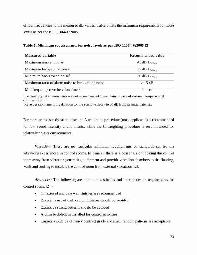
23
of low frequencies to the measured dB values. Table 5 lists the minimum requirements for noise
levels as per the ISO 11064-6:2005.
Table 5. Minimum requirements for noise levels as per ISO 11064-6:2005 [2]
Measured variable Recommended value
Maximum ambient noise 45 dB LAeq, y
Maximum background noise 35 dB LAeq, y
Minimum background noise† 30 dB LAeq, y
Maximum ratio of alarm noise to background noise > 15 dB
Mid-frequency reverberation times‡ 0.4 sec
†Extremely quiet environments are not recommended to maintain privacy of certain inter-personnel
communication ‡Reverberation time is the duration for the sound to decay to 60 dB from its initial intensity
For more or less steady-state noise, the A weighting procedure (most applicable) is recommended
for low sound intensity environments, while the C weighting procedure is recommended for
relatively noisier environments.
Vibration: There are no particular minimum requirements or standards set for the
vibrations experienced in control rooms. In general, there is a consensus on locating the control
room away from vibration generating equipment and provide vibration absorbers to the flooring,
walls and roofing to insulate the control room from external vibrations [2].
Aesthetics: The following are minimum aesthetics and interior design requirements for
control rooms [2] –
Untextured and pale wall finishes are recommended
Excessive use of dark or light finishes should be avoided
Excessive strong patterns should be avoided
A calm backdrop is installed for control activities
Carpets should be of heavy contract grade and small random patterns are acceptable

24
The walls should be lighter than the floors and the ceiling should be lighter than the
walls
Indoor plants and furnishings must be provided to humanize the environment
The wall and ceiling finishes, the carpet design and furnishings should be suitable for
a 24-hour operation
The ISO 11064-6:2005 defines reflectance as the ratio of luminous flux reflected from a
surface to the luminous flux incident on it. Table 6 lists the required ranges of reflectance as per
the standard.
Table 6. ISO 11064-6:2005 – Minimum requirements for reflecting surfaces [2]
Reflecting surface Reflectance value
Floor finishes 0.2-0.3
Wall finishes 0.5-0.6
Partitions 0.5-0.6
White matte ceilings > 0.8
7.2.5. Layout design
The design of control rooms should be based on human-centered approach which gives top
priority to the requirements of the operator. Thus, the architecture of the building should unfold
from within, considering the operator as the starting point. The first step is the design of the
operator’s workstation which is based on the SCADA system relevant for that particular
workstation. The second step is to determine the number of operators based on the workload. The
control room layout is then dictated by the required level of communication and supervision. The
ISO 11064-3 and ISO 11064-2 provide guidelines for control room layout and control suite design,
respectively, and the key considerations are summarized as below –
Control panel equipment should be located to promote visual contact between the
operators tasked to perform related functions.

25
The control zones for operators requiring frequent communication should be placed
close to each other and the layout should allow for direct verbal conversations wherever
practical.
Control zones and rooms with different functions should be physically separated to
avoid potential sources of disturbance.
The layout for control rooms involving large number of operators should allow for
teamworking opportunities and social interactions in cases where these are critical
factors for the success of control room operations.
The overall goal of the layout should be to optimize operational links, direct speech
communications and sightlines for human-human and human-machine interactions.
The layout should strike an effective balance between encouraging collaboration and
reducing the number of distractions between the operators.
The control room layout should consider the requirements of different user groups apart
from the operators, such as the cleaning staff, maintenance staff, IT personnel, managers,
executives and visitors. In case of control rooms operating 24 x 7, the layout should allow for
independent function of the operators during the cleaning and maintenance tasks [2]. Auxiliary
resource areas such as meeting rooms, restrooms, office facilities (printers, copiers, PCs, etc.)
kitchen, resting areas, exercise areas, etc. if required should be located in close proximity of the
control rooms. Recommended best practices suggest displaying critical safety and performance
information and alarms in these auxiliary resource areas as well [2].
7.3. Design principles for future control rooms
7.3.1 Learnings from the airline industry
Noise levels: As discussed in previous sections, noises can be a source of distraction for
control room operators, but there is still a minimum noise requirement for control rooms. A certain
level of noise will provide privacy for quiet conversations, and specific sounds can keep controllers
alert to specific events. Background noises can be found in HVAC systems and computer noises,
but there are sometimes specific sounds which can be beneficial to the operator. An example of
background noises being beneficial can be found in air-traffic control (ATC) centers. A common
noise in an air-traffic control room is a clicking sound when plastic flight strips are moved into

26
their respective slots. Rather than serving as a distraction for the controllers, the noise serves as an
indication of aircrafts in their sector. It would make sense that certain noises within the control
room in a chemical plant could be beneficial to the operator. For example, if two operators are
working jointly on a process where tasks must be completed in succession, an auditory notification
can be passed from the first operator to the second to indicate the second task is ready to be
completed.
Effective communication: Communication between operators as well as between operators
and field-workers is pivotal to the efficiency of a chemical facility. This is especially important
when a plant is using a centralized control room which is located away from the processes it is
monitoring. Workers in the field must be able to effectively communicate information about a
process to an operator in the control room to maintain the operator’s knowledge about the process.
By extension, an operator must be able to effectively communicate to a field-worker about any
issues with a process. The air traffic control industry faces a similar requirement, as air traffic
control operators must be able to effectively transmit information to pilots on approach or during
departure from an airport. The air traffic industry has found that message effectiveness is governed
by two main aspects: message length (complexity), and message timing.
In the airline industry, the level of message comprehension is determined by the number
of readback errors. A message is sent from the controller, and the pilot reads the message back to
indicate comprehension. Ideally, there would be zero errors in the message read back. Message
length can strongly influence the number of readback errors. A study by NASA revealed that
longer messages resulted in more readback errors due to overloading the pilot’s working memory.
It was found that multiple shorter messages are more effective at communicating information to
the pilot. Furthermore, the timing between the messages is also influential. If the second message
is delivered too closely in time with respect to the first message, the pilot’s memory or response
to the first task was negatively affected.
The relationship between the air traffic controller and the pilot is analogous to that of a
field worker and a control room operator. Messages must be sent to and from the control room,
and the effectiveness of the message can be critical to safe operation of the process. Learning from
the airline industry, messages should ideally be shorter, less complex, and appropriately timed to

27
ensure effective communication between the operator and the field. Readback messages should
also be used between control room operators and field workers. Readback messages help to
improve message comprehension, and also provide an indication about the level of accuracy of the
message.
7.3.2. Learnings from the nuclear industry
Effect of situations on operator performance: Apart from the environmental factors such
as temperature, lighting, noise, the nuclear industry has determined that the situations within the
control room are an important aspect to promote effectiveness of operators. The situations describe
the events and disturbances during operations such as start-up, steady-state operation, shutdown,
unexpected outage, as well as different types of external disturbances [6]. The control room
operators should be able to handle such situations and disturbances by having established set of
rules for the operators to react, by having a clear distribution of roles within a shift team and
guidelines for behavior of personnel outside the shift team, so as to not disturb the operators within
the shift team [6].
Control room system – a cognitive model: A study interviewed the staff and operators in
nuclear power plant control rooms and aspects contributing to the safe operation were categorized
into five overall themes – situations, functions, tasks, characteristics and structural elements [6].
Situations describe events and disturbances in the surrounding environment which the control
room should handle. Functions are the abilities of the control room system. Tasks are the
operations which the operators or technical systems in the control room should be able to perform.
Structural elements are the entities that constitute the control room system, and the characteristics
of the structural elements establish conditions for the design of artifacts as well as the behaviors
and abilities of personnel. The interconnections between these themes are described by a cyclical
model as shown in Figure 4. Disturbances are created in the form of situations or events resulting
from the system being controlled, which modify the indicators, gauges or alarms in the control
room while also affecting the response and behavior of the operators. The ability of the operators
to react to these disturbances determines the control actions to be taken and thus produces an effect
on the disturbances created. This cyclical model illustrates how these themes form a joint cognitive
control room design system – such that the outcomes, experiences or events modify the behavior

28
of the system to achieve the goals of safe and reliable operation. Thus, design principles for future
control room design in process industries should consider the whole cognitive system, instead of
focusing individually on specific elements.
Figure 4. Cognitive model connecting the themes identified for safe operation of nuclear
power plant control rooms [6]
8. Conclusions
The design for existing control rooms which were built before the year 2000 has mainly
evolved from large control panels and provides poor consideration for human factors and
ergonomics. Many of these control rooms then received technological upgrades without redesign
of spatial requirements leading to crammed spaces with poor lighting and air quality, and an
ergonomically poor layout. In addition to limited space, the poor design of alarm system leads to
a state of confusion for the operators wherein the alarms are indistinguishable between adjacent
workstations. Absence of separate meeting areas adjacent to these control rooms creates a source
of distraction in the form of conversations and meetings carried out within the control room.

29
A number of standards notably ISO 11064, ISO 92415, EEMUA 991, EEMUA 201 and
literature on human factors and ergonomics provides detailed guidelines for design of control room
elements. The underlying principle among these standards is to foremost consider the requirements
of the operator and therefore design the control center from the operator out. These standards and
literature provide in-depth engineering design principles for the workstation, SCADA systems and
their display requirements, alarm systems, environmental factors (temperature, air quality,
acoustics, vibration, lighting and aesthetics) and the layout of entire control center including
auxiliary resource areas such as kitchen, meeting rooms, restrooms, etc. The standards also account
for correlations between the objectively measured variables and subjectively felt states by the
operators, so that the design principles can closely approximate the “human” experience of the
operators. The standards also provide guidelines for evaluation and audit of existing control rooms
so as to bring them under compliance. The design features and ergonomics of control rooms if
engineered as per these standards can significantly improve the operator performance and work
efficiency by increasing physical comfort, reducing stress levels and minimizing the possibility of
human error.
These existing design principles can be supplemented by learnings from the airline and
nuclear industry. In control rooms of process industries, noise sources from certain control actions
can be utilized to achieve better co-ordination between operators working jointly, similar to the
noise of sliding flight strips in an air traffic control (ATC) room. Also, similar to the
communication between the ATC and pilots, effective communication can be achieved between
control room operators and on field workers by creating guidelines to keep the messages short,
less complex, appropriately timed and to ensure a readback. Further, similar to the nuclear
industry, the negative impact of events/situations on operator’s effectiveness during abnormal
situation handling can be mitigated by preparing a set of guidelines to help the operator handle
these situations. Lastly, similar to the nuclear industry, the human factors in a control room can be
best addressed by considering the control room system including the operators as a single cognitive
system – where the outcomes of the controlled system influence the experience of human
controllers and vice-versa.

30
9. References
[1] M.A.L.& P. Hewitt, What does good control room design look like?,
https://www.controlglobal.com/articles/2016/what-does-good-control-room-design-look-
like, (2016).
[2] N.A. Stanton, P. Salmon, D. Jenkins, G. Walker, Human Factors in the Design and
Evaluation of Central Control Room Operations, CRC Press, (2009).
[3] E. Cochran, P. Bullemer, P. Millner, Effective Control Center Design for a Better Operating
Environment, in: NPRA Computer Conference, (1999).
[4] O.V. Prinzo, The computation and effects of air traffic control message complexity and
message length on pilot readback performance, Measuring Behavior, (2008) 188.
[5] Three Mile Island Accident, United States Nuclear Regulatory Commission,
https://www.nrc.gov/reading-rm/doc-collections/fact-sheets/3mile-isle.pdf, (2014).
[6] E. Simonsen, A.-L. Osvalder, Aspects of the Nuclear Power Plant Control Room System
Contributing to Safe Operation, Procedia Manufacturing, 3 (2015) 1248–1255.
[7] D. Morrow, M. Rodvold, The influence of ATC message length and timing on pilot
communication, National Aeronautics & Space Administration. Contractor Report (1993).
[8] I. Nimmo, J. Moscatelli, Designing Control Rooms for Humans, (2004).
https://www.controlglobal.com/articles/2004/10/.
[9] A. Khan, Control Room Distractions: Recipe for a Catastrophic Disaster, INTECH Process
Automation, (2014). https://www.isa.org/uploadedFiles/WhitePaper-
ControlRoomDistractions.pdf.
[10] A. Hedge, W.A. Erickson, A study of indoor environment and sick building syndrome
complaints in air-conditioned offices: benchmarks for facility performance, International
Journal of Facilities Management. 1 (1997) 185–192.
[11] M. Green, S. Collier, Experiences in incorporating human factors into the control centre
design process, (2001) 19–24.
[12] G.I. Johnson, C.W. Clegg, S.J. Ravden, Towards a practical method of user interface
evaluation, Applied Ergonomics, 20 (1989) 255–260.
[13] D.S. Tan, D. Gergle, P. Scupelli, R. Pausch, With Similar Visual Angles, Larger Displays
Improve Spatial Performance, in: Proceedings of the SIGCHI Conference on Human
Factors in Computing Systems, ACM, New York, NY, USA, (2003) 217–224.
[14] T. Ni, D.A. Bowman, J. Chen, Increased Display Size and Resolution Improve Task
Performance in Information-Rich Virtual Environments, in: Proceedings of Graphics
Interface 2006, Canadian Information Processing Society, Toronto, Ontario, Canada, (2006)
139–146.
[15] A.J. Sabri, R.G. Ball, A. Fabian, S. Bhatia, C. North, High-resolution gaming: Interfaces,
notifications, and the user experience, Interacting with Computers, 19 (2006) 151–166.
[16] N.A. Stanton, C. Baber, Modelling of human alarm handling response times: a case study
of the Ladbroke Grove rail accident in the UK, Ergonomics, 51 (2008) 423–440.