human connectome project (hcp) fmri protocol at cfmri
TRANSCRIPT

©CFMRI Last modified 03/05/2014 1
HumanConnectomeProject(HCP)fMRIprotocolatCFMRI
ContentsHuman Connectome Project (HCP) fMRI protocol at CFMRI ..................................................................................... 1
Introduction ........................................................................................................................................................... 2
The CFMRI HCP Protocol........................................................................................................................................ 3
Run HCP protocol ................................................................................................................................................... 5
Set up and prepare for HCP scan ....................................................................................................................... 5
Scan the HCP protocol ....................................................................................................................................... 5
End exam and transfer Data. ............................................................................................................................. 8
Reconstruct and pre‐process HCP data ................................................................................................................. 8
Data Requirements ............................................................................................................................................ 9
Running the pipeline ......................................................................................................................................... 9
Error Logging ..................................................................................................................................................... 9
Output ............................................................................................................................................................... 9
Appendix I: Summary of Command‐Line Tools.................................................................................................... 10
Appendix II: HCP Pipeline Output files ................................................................................................................ 11
©CFMRI Last modified 03/05/2014 2
Introduction
The Human Connectome Project (HCP) is a 40 million dollar initiative under the NIH Blueprint for Neuroscience
Research1. The project aims to characterize the structural and functional connectivity of the human brain in
order to further our understanding of human brain networks and ultimately advance human health. One of the
key components of the HCP is the acquisition of whole brain functional MRI data at high resolution and high
speed. To enable this component, scientists have developed an HCP protocol that is capable of acquiring whole
brain volume at 2x2x2mm resolution within a TR of 720 msec. The higher resolution and shorter TR greatly
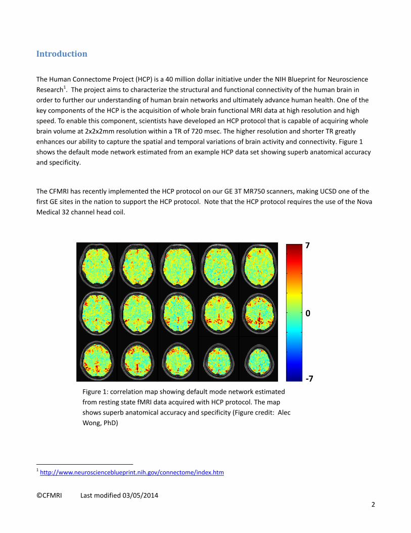
enhances our ability to capture the spatial and temporal variations of brain activity and connectivity. Figure 1
shows the default mode network estimated from an example HCP data set showing superb anatomical accuracy
and specificity.
The CFMRI has recently implemented the HCP protocol on our GE 3T MR750 scanners, making UCSD one of the
first GE sites in the nation to support the HCP protocol. Note that the HCP protocol requires the use of the Nova
Medical 32 channel head coil.
1 http://www.neuroscienceblueprint.nih.gov/connectome/index.htm
Figure 1: correlation map showing default mode network estimated
from resting state fMRI data acquired with HCP protocol. The map
shows superb anatomical accuracy and specificity (Figure credit: Alec
Wong, PhD)
©CFMRI Last modified 03/05/2014 3
TheCFMRIHCPProtocolThe CFMRI HCP protocol can be found on both the 3T West and 3T East scanners under ADULT‐>HEAD‐>HCP.
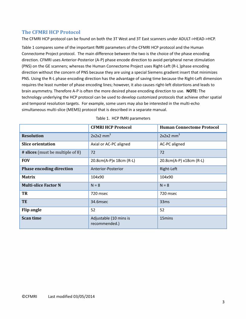
Table 1 compares some of the important fMRI parameters of the CFMRI HCP protocol and the Human
Connectome Project protocol. The main difference between the two is the choice of the phase encoding
direction. CFMRI uses Anterior‐Posterior (A‐P) phase encode direction to avoid peripheral nerve stimulation
(PNS) on the GE scanners; whereas the Human Connectome Project uses Right‐Left (R‐L )phase encoding
direction without the concern of PNS because they are using a special Siemens gradient insert that minimizes
PNS. Using the R‐L phase encoding direction has the advantage of saving time because the Right‐Left dimension
requires the least number of phase encoding lines; however, it also causes right‐left distortions and leads to
brain asymmetry. Therefore A‐P is often the more desired phase encoding direction to use. NOTE: The
technology underlying the HCP protocol can be used to develop customized protocols that achieve other spatial
and temporal resolution targets. For example, some users may also be interested in the multi‐echo
simultaneous multi‐slice (MEMS) protocol that is described in a separate manual.
Table 1. HCP fMRI parameters
CFMRIHCPProtocol HumanConnectome Protocol
Resolution 2x2x2 mm3 2x2x2 mm3
Sliceorientation Axial or AC‐PC aligned AC‐PC aligned
#slices(mustbemultipleof8) 72 72
FOV 20.8cm(A‐P)x 18cm (R‐L) 20.8cm(A‐P) x18cm (R‐L)
Phaseencodingdirection Anterior‐Posterior Right‐Left
Matrix 104x90 104x90
Multi‐sliceFactorN N = 8 N = 8
TR 720 msec 720 msec
TE 34.6msec 33ms
Flipangle 52 52
Scantime Adjustable (10 mins is recommended.)
15mins
©CFMRI Last modified 03/05/2014 4
The HCP protocol consists of the following scans:
1. Localizer (~ 15sec)
2. ASSET calibration (~6 sec)
3. FSPGR (~10mins, adjustable) : T1 weighted high resolution scan
4. HOS(~30 sec): High order shim
5. HCP calibration fwd (~18 sec): Calibration (forward phase encoding)
6. HCP fMRI fwd(10mins, adjustable): functional or resting fMRI scan (forward phase encoding)
7. HCP calibration rvs (~18 sec): Calibration (reversed phase encoding)
8. HCP fMRI rvs(10mins, adjustable): functional or resting fMRI scan (reversed phase encoding)
9. HCP_topup_fwd(~6 sec): TOPUP scan (forward phase encoding)
10. HCP_topup_rvs(~6 sec): TOPUP scan (reversed phase encoding)
The protocol as listed acquires fMRI data in both forward and reverse phase encoding directions (scans 6 and 8),
as is done by the HCP. However, it is also possible to acquire the HCP data in just one phase‐encoding direction
(e.g. one could either omit the rvs calibration and fMRI scans (7 and 8) or omit the fwd calibration and fMRI
scans (5 and 6)). Reversing the phase encoding direction causes the image distortions to flip. For example,
forward phase encoding direction usually causes voxels to shift posteriorly, causing stretching of the back of the
brain (e.g. occipital cortex) and compression in the front of the brain; whereas the reverse phase encoding
direction shifts voxels anteriorly, causing bunching in the back and stretching in the front of the brain. Signal
bunching is more difficult to correct than stretching using the existing field‐mapping methods. Therefore users
may choose the phase encoding direction accordingly to whether the focus is on the front or the back of the
brain. If the preference is the whole brain, we have found that the reverse phase encoding direction is more
beneficial in recovering the frontal lobe signal dropout after field map correction.
The duration of the fMRI scan can be adjusted. Typically we recommend 10 minutes for resting state scans, as
longer scans make it increasingly difficult for subjects to stay still and focused (i.e. fall asleep). The Human
Connectome Project acquires 15 minute long resting state scans.
A calibration scan with matching phase encoding direction is required for the fMRI scans. If there are multiple
fMRI scans with the same phase encoding direction, only one calibration scan with matching phase encoding
direction is needed.
The topup_fwd and topup_rvs scan pair are used to measure a fieldmap which can be applied to the fMRI
images for correcting geometric distortions. They are typically scanned immediately before or after the fMRI
scans. In cases of a scan session containing several fMRI scans in a row where there is concern about subject
motion during the session, users may acquire one topup scan pair before the fMRI scans and another pair at the
end of the session. The first pair can be used for correcting the fMRI data before the motion occurs, and the
second pair for correcting the fMRI data after the motion.
©CFMRI Last modified 03/05/2014 5
RunHCPprotocol
SetupandprepareforHCPscan
1. Place the 32channel coil on the scanner table and plug it in. Make sure the coil is recognized by the
scanner by checking on the iROC monitor on top of the scanner.
2. Set up peripheral equipment such as the projector, screen, and stimulus laptop etc.
3. Set up the subject on the scanner patient table.
4. Setup physiological monitoring if needed.
5. On the console computer, click the downward arrow on the Tools icon. In the drop down menu, select
Command Window. In the command window type ‘RTctrl start’ to start realtime. Drag this window to
the lower right corner of the screen so it is easily accessible and not in the way. (NOTE: this step must
be done before Start Exam in step 6)
6. Register the subject and Start Exam.
ScantheHCPprotocol
1. Localizer
Save Rx and Scan
2. Asset Cal
Setup, Prescribe Rx, Save Rx, and Scan
3. FSPGR T1
Setup, Prescribe Rx, Save Rx, and Scan.
NOTE: while waiting for the FSPGR to finish, prescribe and save the first hcp calibration scan immediately
below the HOS scan. The slices could be either axial or AC‐PC aligned (Human Connectome Project uses AC‐
PC). Please do not change number of slices (72 slices). This step must be done before running the HOS
scan.
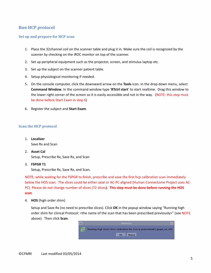
4. HOS (high order shim)
Setup and Save Rx (no need to prescribe slices). Click OK in the popup window saying “Running high
order shim for clinical Protocol: <the name of the scan that has been prescribed previously>” (see NOTE
above). Then click Scan.
©CFMRI Last modified 03/05/2014 6
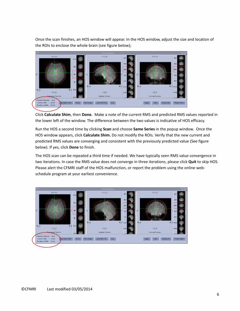
Once the scan finishes, an HOS window will appear. In the HOS window, adjust the size and location of
the ROIs to enclose the whole brain (see figure below);
Click Calculate Shim, then Done. Make a note of the current RMS and predicted RMS values reported in
the lower left of the window. The difference between the two values is indicative of HOS efficacy.
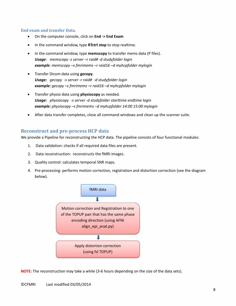
Run the HOS a second time by clicking Scan and choose Same Series in the popup window. Once the
HOS window appears, click Calculate Shim. Do not modify the ROIs. Verify that the new current and
predicted RMS values are converging and consistent with the previously predicted value (See figure
below). If yes, click Done to finish.
The HOS scan can be repeated a third time if needed. We have typically seen RMS value convergence in
two iterations. In case the RMS value does not converge in three iterations, please click Quit to skip HOS.
Please alert the CFMRI staff of the HOS malfunction, or report the problem using the online web‐
schedule program at your earliest convenience.

©CFMRI Last modified 03/05/2014 7
5. hcp_cal_fwd (see NOTE below)
download and scan.
6. hcp_rest_fwd (see NOTE below)
Copy Rx, save Rx, download , and scan.
7. hcp_cal_rvs (see NOTE below)
Copy Rx, , save Rx, download and scan.
8. hcp_rest_rvs (see NOTE below)
Copy Rx, , save Rx, download, and scan.
9. hcp_topup_fwd (see NOTE below)
Copy Rx, , save Rx, download and scan.
10. hcp_topup_rvs (see NOTE below)
Copy Rx, , save Rx, download and scan.
NOTE:
Each of the hcp scans (scan 5‐10) needs to be downloaded prior to starting the respective scan.
The download step ensures that the RDS client is started to receive the acquired MRI data. If
the RDS client is not ON, no MRI data will be saved.
Below are some useful tools:
o Type ck in the command window to check if the RDS client is ON. If not ON, stop the hcp
scan, copy & paste the scan, download. Type ck again to make sure RDS client is ON, then
Scan.
o Type memslist in the command window to list the raw data files. Anytime during an hcp
scan, use memslist to check if data is being saved.
If an hcp scan has to be stopped before it finishes, for example when subject activates the
emergency squeeze ball, please do the following:
o Type kk in the command window to kill the RDS client then press Stop Scan button. After
the emergency situation or errors are cleared, copy & paste the scan, download and Scan.
o If the Stop Scan button is pressed before the RDS client is killed, a TPS reset must be
performed before the scan can continue. A TPS reset usually takes 2‐3 minutes. After the
TPS reset, copy & paste the scan, download and Scan.
Due to limitations with the RDS server software, after an hcp scan finishes, the status of the
scan shows “Action Failed”. You can ignore this status. Additionally, as soon as the next scan is
downloaded, the previous hcp scan is pushed downward in the scan list. This tends to cause
confusion. Please pay attention to which scan is the currently active scan.
Appendix I lists all command‐line tools available for use with the HCP protocol.
©CFMRI Last modified 03/05/2014 8
EndexamandtransferData. On the computer console, click on End ‐> End Exam
In the command window, type RTctrl stop to stop realtime.
In the command window, type memscopy to transfer mems data (P files).
Usage: memscopy ‐s server –r raid# ‐d studyfolder login
example: memscopy –s fmrimems –r raid16 –d myhcpfolder mylogin
Transfer Dicom data using gecopy.
Usage: gecopy ‐s server ‐r raid# ‐d studyfolder login
example: gecopy –s fmrimems –r raid16 –d myhcpfolder mylogin
Transfer physio data using physiocopy as needed.
Usage: physiocopy ‐s server ‐d studyfolder starttime endtime login
example: physiocopy –s fmrimems –d myhcpfolder 14:00 15:00 mylogin
After data transfer completes, close all command windows and clean up the scanner suite.
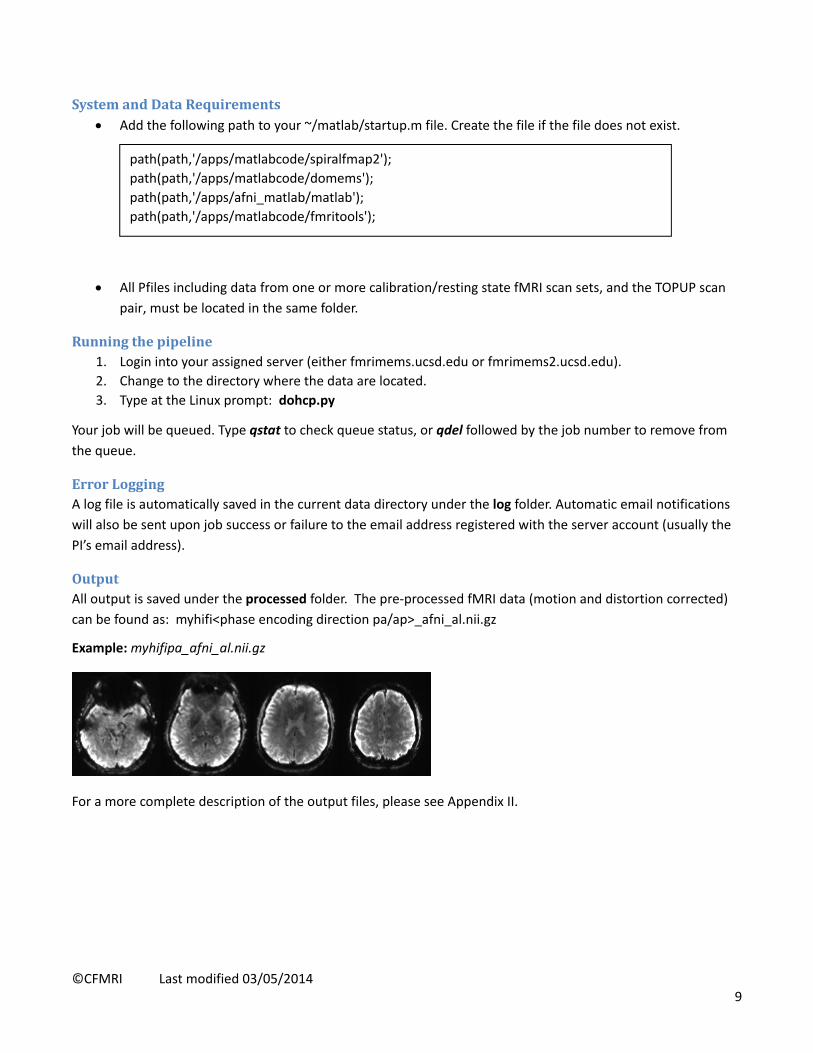
Reconstructandpre‐processHCPdataWe provide a Pipeline for reconstructing the HCP data. The pipeline consists of four functional modules:
1. Data validation: checks if all required data files are present.
2. Data reconstruction: reconstructs the fMRI images.
3. Quality control: calculates temporal SNR maps.
4. Pre‐processing: performs motion correction, registration and distortion correction (see the diagram
below).
NOTE: The reconstruction may take a while (3‐6 hours depending on the size of the data sets).
Motion correction and Registration to one
of the TOPUP pair that has the same phase
encoding direction (using AFNI
align_epi_anat.py)
fMRI data
Apply distortion correction
(using fsl TOPUP)
©CFMRI Last modified 03/05/2014 9
SystemandDataRequirements Add the following path to your ~/matlab/startup.m file. Create the file if the file does not exist.
All Pfiles including data from one or more calibration/resting state fMRI scan sets, and the TOPUP scan
pair, must be located in the same folder.
Runningthepipeline1. Login into your assigned server (either fmrimems.ucsd.edu or fmrimems2.ucsd.edu).
2. Change to the directory where the data are located.
3. Type at the Linux prompt: dohcp.py
Your job will be queued. Type qstat to check queue status, or qdel followed by the job number to remove from
the queue.
ErrorLoggingA log file is automatically saved in the current data directory under the log folder. Automatic email notifications
will also be sent upon job success or failure to the email address registered with the server account (usually the
PI’s email address).
OutputAll output is saved under the processed folder. The pre‐processed fMRI data (motion and distortion corrected)
can be found as: myhifi<phase encoding direction pa/ap>_afni_al.nii.gz
Example: myhifipa_afni_al.nii.gz
For a more complete description of the output files, please see Appendix II.
path(path,'/apps/matlabcode/spiralfmap2');
path(path,'/apps/matlabcode/domems');
path(path,'/apps/afni_matlab/matlab');
path(path,'/apps/matlabcode/fmritools');

©CFMRI Last modified 03/05/2014 10
AppendixI:SummaryofCommand‐LineTools
Command Usage Description
RTctrlstart RTctrl start Start Realtime (Must be done before “Start Exam”)
RTctrlstop RTctrl stop End Realtime (Must be done after “End Exam”)
ck Ck Check if RDS client is ON
kk kk Kill all active RDS clients
memslist memslist List raw data files of the current MEMS scan session.
memscopy memscopy ‐s server ‐d studyfolder login Transfer HCP raw data files to server.
gecopy gecopy ‐s server ‐r raid# ‐d studyfolder login
Transfer DICOM files to server.
physiocopy physiocopy ‐s server –d studyfolder starttime endtime login
(*starttime and endtime format: hh:mm)
Transfer physio files to fmrimems server.
cdtail
cd /export/home/sdc/RTafni/var/log tail –f <last log file name>
Check realtime status and messages
©CFMRI Last modified 03/05/2014 11
AppendixII:HCPPipelineOutputfilesAll outputs are saved under “processed” folder. Below is a list of selected outputs that users may examine for
sanity check purpose or for trouble shooting when there are errors in the reconstruction process. Users should
contact CFMRI ([email protected]) for questions regarding these files.
bcaipi_spep_hcp_rest_<phase encoding dir>brik+orig.BRIK Example: bcaipi_spep_hcp_rest_fwdbrik+orig.BRIK
rest<phase encoding dir>.nii.gz Example: restpa.nii.gz, restap.nii.gz
Reconstructed fMRI data in BRIK and NIFTI format before motion correction and distortion correction. These images have visible distortions, but should be free of obvious artifacts, and have typical T2* BOLD contrast (the example below shows four brain slices acquired in reversed phase encoding direction).
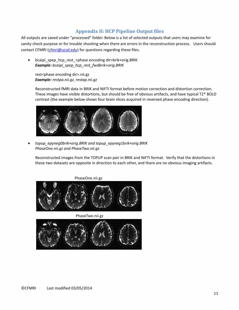
topup_epyneg0brik+orig.BRIK and topup_epyneg1brik+orig.BRIK PhaseOne.nii.gz and PhaseTwo.nii.gz
Reconstructed images from the TOPUP scan pair in BRIK and NIFTI format. Verify that the distortions in these two datasets are opposite in direction to each other, and there are no obvious imaging artifacts.
PhaseOne.nii.gz
PhaseTwo.nii.gz
©CFMRI Last modified 03/05/2014 12
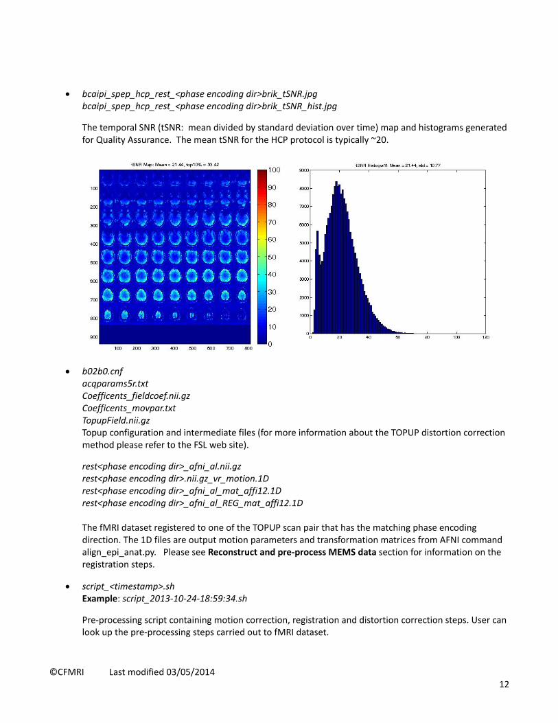
bcaipi_spep_hcp_rest_<phase encoding dir>brik_tSNR.jpg bcaipi_spep_hcp_rest_<phase encoding dir>brik_tSNR_hist.jpg
The temporal SNR (tSNR: mean divided by standard deviation over time) map and histograms generated for Quality Assurance. The mean tSNR for the HCP protocol is typically ~20.
b02b0.cnf acqparams5r.txt Coefficents_fieldcoef.nii.gz Coefficents_movpar.txt TopupField.nii.gz Topup configuration and intermediate files (for more information about the TOPUP distortion correction method please refer to the FSL web site).
rest<phase encoding dir>_afni_al.nii.gz rest<phase encoding dir>.nii.gz_vr_motion.1D rest<phase encoding dir>_afni_al_mat_affi12.1D rest<phase encoding dir>_afni_al_REG_mat_affi12.1D The fMRI dataset registered to one of the TOPUP scan pair that has the matching phase encoding direction. The 1D files are output motion parameters and transformation matrices from AFNI command align_epi_anat.py. Please see Reconstruct and pre‐process MEMS data section for information on the registration steps.
script_<timestamp>.sh Example: script_2013‐10‐24‐18:59:34.sh
Pre‐processing script containing motion correction, registration and distortion correction steps. User can look up the pre‐processing steps carried out to fMRI dataset.