ht-sui-surveillant iom 3 22 2013
TRANSCRIPT

Surveillant Demand Defrost
Evaporator Control
Installation and Operations Manual
HT-SUI-0313A
Page 2
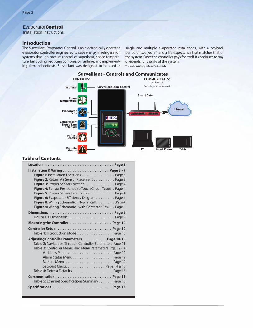
IntroductionThe Surveillant Evaporator Control is an electronically operated evaporator controller engineered to save energy in refrigeration systems through precise control of superheat, space tempera-ture, fan cycling, reducing compressor runtime, and implement-ing demand defrosts. Surveillant was designed to be used in
Surveillant - Controls and Communicates
single and multiple evaporator installations, with a payback period of two years*, and a life expectancy that matches that of the system. Once the controller pays for itself, it continues to pay dividends for the life of the system.*based on utility rate of $.09/kWh
Location . . . . . . . . . . . . . . . . . . . . . . . . . . . . Page 3
Installation & Wiring . . . . . . . . . . . . . . . . . . . Page 3 - 9
Figure1: Installation Locations . . . . . . . . . . . . . . Page 3 Figure 2: Return Air Sensor Placement . . . . . . . . . Page 3 Figure 3: Proper Sensor Location . . . . . . . . . . . . . Page 4 Figure 4: Sensor Positioned to Touch Circuit Tubes . Page 4 Figure 5: Proper Sensor Positioning . . . . . . . . . . . Page 4 Figure 6: Evaporator Effi ciency Diagram . . . . . . . . Page 6 Figure 8: Wiring Schematic - New Install . . . . . . . . .Page7 Figure 9: Wiring Schematic - with Contactor Box . . . Page 8
Dimensions . . . . . . . . . . . . . . . . . . . . . . . . . . Page 9
Figure 10: Dimensions . . . . . . . . . . . . . . . . . . . Page 9
Mounting the Controller . . . . . . . . . . . . . . . . . Page 10
Controller Setup . . . . . . . . . . . . . . . . . . . . . . Page 10
Table 1: Introduction Mode . . . . . . . . . . . . . . . Page 10
Adjusting Controller Parameters . . . . . . . . . . Page 10-15
Table 2: Navigation Through Controller Parameters Page 11 Table 3: Controller Menus and Menu Parameters Pgs. 12-14 Variables Menu . . . . . . . . . . . . . . . . . . . Page 12 Alarm Status Menu . . . . . . . . . . . . . . . . . Page 12 Manual Menu . . . . . . . . . . . . . . . . . . . . Page 12 Setpoint Menu . . . . . . . . . . . . . . . . . Page 14 & 15 Table 4: Defrost Defaults . . . . . . . . . . . . . . . . . Page 13
Communication . . . . . . . . . . . . . . . . . . . . . . . Page 13
Table 5: Ethernet Specifi cations Summary . . . . . . Page 13
Specifi cations . . . . . . . . . . . . . . . . . . . . . . . . Page 13
Table of Contents
Smart Phone
TEV/EEV
EvaporatorFans
DefrostHeaters
RoomTemperature
MultipleAlarms
Compressor/Liquid Line
Solenoid
ENTER
BACK
2 52222222222222222222 55555555555
Surveillant Evap. Control
Smart Gate
Tablet
RB201 1UAS-2HND-IN
USB
SFP
POE GIGABIT ETHERNET
ETH1 ETH5ETH3 ETH4ETH2 ETH6 ETH10ETH8 ETH9ETH76 7 8 9 10
1 2 3 4 5FAST ETHERNET
MODIFY STATUSABC Contracting(888)555-3358
All ClearCompressorOn
System ModeCool
Evaporator FanOff
Room Temp-8.5 F
Coil Temp15.4 F
Sat Temp46.0 F
Superheat0.0 F
Valve PositionManual
Suct Pressure96.2 F
Suct Temp87.7 F
Dig Input 3Dis
DefrostOff
Aux TempDis
Dig Input 1Closed
Dig Input 2Dis
MODIFY STATUSABC Contracting(888)555-3358
All ClearCompressorOn
System ModeCool
Evaporator FanOff
Room Temp-8.5 F
Coil Temp15.4 F
Sat Temp46.0 F
Superheat0.0 F
Valve PositionManual
Suct Pressure96.2 F
Suct Temp87.7 F
Dig Input 3Dis
DefrostOff
Aux TempDis
Dig Input 1Closed
Dig Input 2Dis
PC
Internet
CONTROLS: COMMUNICATES:Locally on site
or Remotely via the Internet
EvaporatorControl Installation Instructions

Page 3
for easy viewing of the room temperature and/or system status. See Figure 1 for locations.
If installing the controller on the face of the evaporator, preexist-ing knockouts on the evaporator should be used for installing the high voltage wiring. If knockouts do not preexist, hole(s) may be carefully cut into an unobstructed area of the evapora-tor case. If modifying the face of the evaporator is not feasible or desired, the controller’s conduit knockouts may be used with ½ inch conduit.
The bottom side of the controller includes a cutout with cable tie slots providing a strain relief for the low voltage and sensor wires. Additional knockouts are available on either side if con-duit is preferred.
Installation & WiringThe Surveillant Evaporator Control is supplied with pluggable connectors for all connections. Pluggable connectors permit the controller to be placed in a safe location while the wiring is installed. They also simplify the wiring, allowing the wires to be fastened to the screw terminals in the open air. Once all wiring is completed using accepted wiring practices, it is plugged into the controller prior to fi nal mounting.
Although there is one pressure transducer and four tempera-ture sensor inputs, when used with mechanical valves (TEVs), Surveillant only requires the (3) sensors supplied with the kit.
One sensor reads the return air temperature and the other two measure the coil temperature. NOTE! Sensor location is critical
to the proper operation of the controller.
Return Air Temperature Sensor - The air temperature sensor is installed in the return air of the evaporator using the included sensor mount. Most applications allow the sensor mount to be installed using an existing screw. On evaporators where us-ing an existing screw is not possible, the included self-tapping screw may be used to secure the sensor mount to the evapora-tor. Note: Be careful to avoid damage to an evaporator tube
or causing a leak in the drip pan. When installing, it is impor-tant to prevent the air sensor from coming into contact with the mounting bracket, cable ties, or any other solid material. Figure
2 shows an example of how to mount the sensor. The sensor must be a minimum of 6 inches from the coil surface.
LocationSurveillant Evaporator Control was developed with ease of in-stallation in mind. The controller is supplied in an enclosure, with encapsulated electronics to protect the circuitry from moisture damage. This extra level of protection allows the con-troller to be installed in the refrigerated space.
When installing the controller, it may either be mounted on an interior/exterior wall or on the evaporator. Many evapora-tors have suffi cient space to install the controller on the face of evaporator or on its housing. Locating the controller as close to the evaporator as possible reduces the amount of wiring when converting existing systems, as well as when it is applied on new applications.
Alternatively, users may fi nd it benefi cial to install the controller in a location providing easy access -- on the wall or near the en-trance. This enables the user to easily view the display, and elim-inates the need to use a ladder or lift to modify the setpoints or check alarms.
If viewing the temperature outside the walk-in or refrigerated room is desirable, Surveillant may be used as a digital thermo-stat. The controller is then installed near the door of the space
ENTER
BACK
22
ENTER
BACK
2
ENTER
BACK
22
On the wall
On the evaporator
At the entrance
Figure 1. Installation Locations
Air Sensor
>6”
Return Air
Figure 2 - Return Air Sensor Placement
EvaporatorControl Installation Instructions

Page 4
After the sensor is installed, route the wire back to the control-ler location. When routing sensor wire, it is important to avoid interference from high voltage lines. If sensor wire is run parallel to the high voltage, there is a potential for inductance to aff ect the sensor reading. This is of particular concern with long wire runs. When extending sensors, use the 18 gage, shielded twist-ed pair. Sensor wires can be run beyond 100 feet when using 18 gage twisted shielded pair. After the wire has been successfully routed, it may be connected to the pluggable terminal on the controller.
Coil Temperature Sensor - As a critical input to the control-ler, it is essential the sensor is located at the coldest point on
the evaporator coil for optimal operation. The coil sensor is an integral part of the control algorithm used to determine coil ef-fi ciency, to initialize defrosts, and to terminate defrosts.
Determine the coil sensor locationTo determine the most appropriate sensor location, when
arriving on site, put the system into defrost. The location
where frost is last to disappear is where the coil sensor
should be placed. Monitor both the air entering side, as well as the air exiting side, of the evaporator coil. Don’t be surprised if the last place for frost to disappear is on the air exiting side. It is usually near the right or left end of the coil.
Steps to Ensure Proper Coil Sensor Location
For more robust installations, it is recommended that two coil sensors are used, located as described above. Typically the cold-est spot is on the side of the suction header/expansion valve side of the evaporator. Select two places that are the last to de-frost, preferably at each end of the evaporator.
More often than not on coils, the location of the sensor is a short distance from the end, approximately 1 to 1-1/2” away from the right and left edges of the active coil surface. The ice tends to grow from these edges towards the center. Therefore, the sen-sor location is best situated approximately 1 to 1-1/2” from the outer edges and typically near the bottom 1/3rd portion of the evaporator. The sensor needs to be as far away from the defrost heat sources as possible. See Figure 3.
Locating the sensor too close to the elements will cause false defrost termination temperatures. It is important to note, the most active portion of the sensor is the fi rst 1/2” of the 1-1/2” long stainless steel probe. As a result, it is important to touch two circuit tubes. When inserting the sensor into the coil, the tip should touch one of the circuit tubes. This location is appropri-ate for the sensor. Figure 4 shows the proper sensor position.
When choosing the location, the sensor should not be located adjacent to the electric heating elements. The sensor should be approximately half the distance between the heaters if possible. Insert the probe into the fi ns approximately 1/16” deeper than the stainless shielding of the probe. Pinch the two fi ns gently together to secure the sensor in place. This provides the thermal ballast to ensure a complete defrost every time. See Figure 5.
Locate sensor approx. 1-1/2” from end, in thebottom third of coil
Locate senLocate
Figure 3 - Proper Sensor Location
Figure 4 - Sensor Positioned to Touch Two Circuit Tubes
Figure 5 - Proper Sensor Positioning
EvaporatorControl Installation Instructions

It is important to verify all heating elements are working properly.
Due to the many factors infl uencing the evaporator perfor-mance, it is impossible to provide the proper location of every installation. However, the coil sensor is an integral part of the control algorithm used to determine coil effi ciency to initiate, as well as, terminate defrosts. The coldest point in the coil can be identifi ed from existing system knowledge or by monitoring the normal operation.
Controller Power - The high voltage wiring is protected by a metal shield fastened to the back side of the controller. The shield should be removed to gain access to the wiring connec-tions, making note of the location of the fasteners. The screws in the upper corners are coarse thread screws, while the screw in the middle is a 4-40 machine screw.
The controller accepts either 120V or 208/240V incoming power. The controller includes metal oxide varistors (MOVs), providing protection from voltage spikes. MOVs use the same technology commonly applied to protect consumer electronics. They func-tion by fi ltering out voltages high enough to damage the board. When the voltage exceeds the allowed amount, the MOVs short to ground, protecting the circuitry. For additional protection, the board has a replaceable BK/MDL-1/4 fuse in line. The grey plug is accessible without removing the metal shield in the fuse holder. Depress slightly and turn 1/4 turn counterclockwise to remove. Replace by depressing slightly and turning 1/4 turn clockwise. Do not overtighten.
The board uses a pluggable screw terminal connector to con-nect incoming power. The terminal is located in the top right corner of the controller when the terminals are facing the user. See Figure 6.
Fan and Defrost Relays - There are 2 larger relays on the con-troller with spade connectors. These are used for the evaporator fans and defrost heaters. Due to the spacing of the enclosure the spades require a 90 degree terminal. Spade connectors (4) are included to assist in wiring the relays.
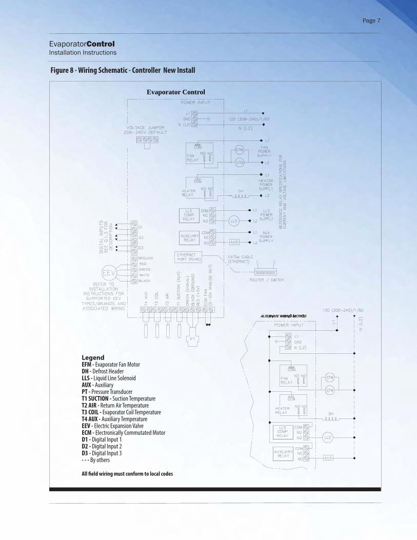
Evaporator Fan Relay - The fan relay is rated 10A inductive at 240V. One leg of the incoming power (L1) for the fans should be connected to the COM terminal of the fan relay, the upper of the two larger relays. The remaining leg, (L2) should be con-nected to one lead of the fan. The remaining fan lead should be connected to the NO (Normally Open) terminal on the fan relay. See Figure 8.
Defrost Heater Relay - The heater relay is rated 20A resistive at 240V. One leg of the incoming power (L1) for the heaters should be connected to the COM terminal of the heater relay, the lower of the two larger relays. The remaining leg, (L2) should be connected to one lead of the heater. The remaining heater lead should be connected to the NO (Normally Open) terminal on the heater relay.
Compressor/Liquid Line Solenoid Relay - The compressor re-lay is rated at 3A inductive at 240V. This relay uses the 3-position pluggable screw terminal to make the connection to the board. The relay is not intended to control the compressor directly. It is designed to be used to control the liquid line solenoid or as a pi-lot to the compressor contactor. One leg of the incoming power supply (L1) should be connected to COM terminal of the com-pressor relay, the upper of the two smaller relays. The remaining leg, (L2), should be connected to one lead on the solenoid/com-pressor contactor. The remaining lead, should be connected to the normally open (NO) position on the terminal.
Auxiliary Relay - The auxiliary relay is rated at 3A inductive at 240V. This relay uses the 3-position pluggable screw terminal to make the connection to the board. The relay may be con-nected to a variety of devices. One leg of the incoming power supply (L1) should be connected to COM terminal of the auxil-iary relay, the lower of the two smaller relays. The remaining leg, (L2), should be attached to one lead on the connected device. The remaining alarm lead, should be connected to the normally open (NO) position on the terminal.
After all high voltage wiring is completed the metal shield
must be replaced and screws tightened.
Additional InputsSuction Temperature Sensor (T1 Auxiliary) - The suction tem-perature sensor is required when applying the controller with an electronic expansion valve. The sensor’s proximity to the evaporator outlet diff ers slightly for electronically controlled valves from the placement of a TEV bulb. Due to the more re-fi ned control from an electronically controlled valve, the sen-sor must be placed as close to the outlet of the coil as feasible. Although the distance from the outlet is diff erent, the nature of the refrigerant’s fl ow through the tube remains unchanged, thus the orientation of the sensor remains at the 4 or 8 o’clock position. The sensor should be secured to the suction line using the included wire ties designed for low ambient operation. In addition to being confi gured as a suction sensor, the T1 input may also be confi gured like the auxiliary sensor.
Pressure Transducer - In addition to the suction temperature sensor, a pressure transducer is also required for superheat measurement when applying a Hybrid Stepper Valve (HSV). The pressure tap should be mounted on the top of a horizontal sec-tion of tube. It should be located near the suction sensor, ap-proximately 3 inches downstream from the position of the tem-perature sensor.
Auxiliary Temperature Sensor -The auxiliary temperature sen-sor provides fl exibility and may be used for any purpose desired by the user. The placement of the sensor is dependent on the requirements of the user’s intended application. The Auxiliary Temperature sensor must be supplied by HTPG.
Digital Inputs - The controller includes (3) digital inputs. See Table 3 for confi guration options.
EvaporatorControl Installation Instructions
Page 5

Page 6
Figure 6 - Surveillant Evaporator Control - Diagram (back view)
208-240
120120
Temperature Sensors Pressure TransducerT1SuctT4Aux T2AirT3Coil
line / L1
groundneutral / L2
NCNO
NO NC
NO NC
COM
COM
NC
Power In
gree
n
red
blac
kNO
Transformer
3A Relay
3A Relay COM
COM
COMNCNO
COMNCNO
18V
DI 1
DI 3
DI 2
Electric Valve*
Temperature Sensors (4) Pressure Transducer
RJ45 Ethernet Connection
DAC for ECM Fan
Fuse
groundredgreenwhiteblack
Alarm Relay
Fan Relay (10 amp)
groundsignal +5
Defrost (Heater) Relay(20 amp)
Bk/MDL-1/4Time Delay
Liquid Line Solenoid
Power In
(compressor)
door switchsystem off
dual temp settingexternal alarm
light switchdefrost interlock
defrost lockout
Digital Inputs
Pressure Transducer Wiring Detail black
red
green
VoltageSelector
120V - Jumpers
1&2 3&4
208-240V Jumper
2&3 only
1 2 3 4
yellowblueredwhiteblack
browngreenwhiteyellow
*Beacon® I
*Beacon® II
blueredwhiteblack
*Beacon® II
0-10V analog out
+_
EvaporatorControl Installation Instructions
Page 7
EvaporatorControl Installation Instructions
Figure 8 - Wiring Schematic - Controller New Install
LegendEFM - Evaporator Fan MotorDH - Defrost HeaderLLS - Liquid Line SolenoidAUX - AuxiliaryPT - Pressure TransducerT1 SUCTION - Suction TemperatureT2 AIR - Return Air TemperatureT3 COIL - Evaporator Coil TemperatureT4 AUX - Auxiliary TemperatureEEV - Electric Expansion ValveECM - Electronically Commutated MotorD1 - Digital Input 1D2 - Digital Input 2D3 - Digital Input 3- - - By others
All fi eld wiring must conform to local codes
Evaporator Control

Page 8
Evap
orat
or F
an M
otor
sCo
n1
Max
HP
& A
mp
Rat
ings
(Tot
al A
ll Fa
ns)
Volt
age
Max
HP
Max
AM
PS
230 3
Ø15
4246
0 3Ø
3040
575 3
Ø30
32
Figu
re 9
- W
irin
g Sc
hem
atic
- Co
ntr
olle
r w
ith
Con
tact
or B
ox
Exis
tin
g D
efro
st H
eate
rs M
ax C
urr
ent
Rat
ings
(Am
ps a
re T
otal
All
Hea
ters
)
Rel
ay B
ox P
/N23
0V 3
Ø46
0V 3
Ø57
5V 3
Ø20
217
54 Am
ps52
Amps
52 Am
ps20
218
68 Am
ps65
Amps
62 Am
ps20
219
80 Am
ps77
Amps
62 Am
ps
Le
ge
nd
EFM
- Ev
apor
ator
Fan M
otor
DH
- De
frost
Head
erLL
S - L
iquid
Line S
oleno
idAU
X - A
uxilia
ryP
T - P
ressu
re Tr
ansd
ucer
T1 S
UCT
ION
- Su
ction
Tem
pera
ture
T2 A
IR -
Retu
rn Ai
r Tem
pera
ture
T3 C
OIL
- Eva
pora
tor C
oil Te
mpe
ratu
reT4
AU
X - A
uxilia
ry Te
mpe
ratu
reEE
V -
Electr
ic Ex
pans
ion Va
lveEC
M - E
lectro
nicall
y Com
mut
ated
Mot
orD
1 - D
igita
l Inpu
t 1D
2 - D
igita
l Inpu
t 2D
3 - D
igita
l Inpu
t 3- -
- By
othe
rs
All
fi el
d w
irin
g m
ust
con
form
to
loca
l cod
es
Con
tact
or r
atin
gs p
er U
L508
CSA
22.
2
Figure 9 - Wiring Schematic - Controller with Contactor Box
EvaporatorControl Installation Instructions
Surv
eilla
nt E
vapo
rato
r Con
trol
ler

Page 9
EvaporatorControl Installation Instructions
R 0.210
R 0.105
11.75
9.0
0.5
2.2
6.75
1.40
0.67
0.95
5.75
2.03
6.5
female 1/4” SAE with depressor
Temperature Sensor
10.0 ft.
.25
1.50
1.50
0.187
Figure 10 - Dimensions (front view)
Dimensions - InchesDepth 2.45”
Page 10
Mounting the Controller Once the wiring has been run to the controller location, the con-troller can be connected. When installing the Surveillant Evapo-rator Control, the (4) screws supplied in the kit may be prein-stalled in the mounting surface. The controller has keyholes in each mounting tab to allow the controller to be installed over the screws.
User InterfaceThe Surveillant’s onboard user interface uses a familiar 6-but-ton arrangement to simplify navigation through the controller’s menus. The menu has been grouped by category to provide an easy to program structure. By grouping the menu by each func-tional area, the user is not required to scroll though unrelated parameters to access the desired functionality.
The left and right arrows move between the categories. When pressed while in a menu, the left and right arrows will move to the main screen or the adjacent menu.
The up and down arrows move the user through the available options for each group. All users are allowed access to the vari-able alarms. All other information is password protected to pre-vent unauthorized access to the controller’s functionality.
The ENTER button is used to save an input option when it has-been changed. The enter button must be held for 3 seconds
to prevent accidental changes. Changes may be discarded by waiting, to allow the controller to timeout and return to default screen, or hitting the BACK button.
The BACK button is used to return to the previous screen. Press-ing the BACK button three times at any time will return the user to the default view. See Table 2 (following page).
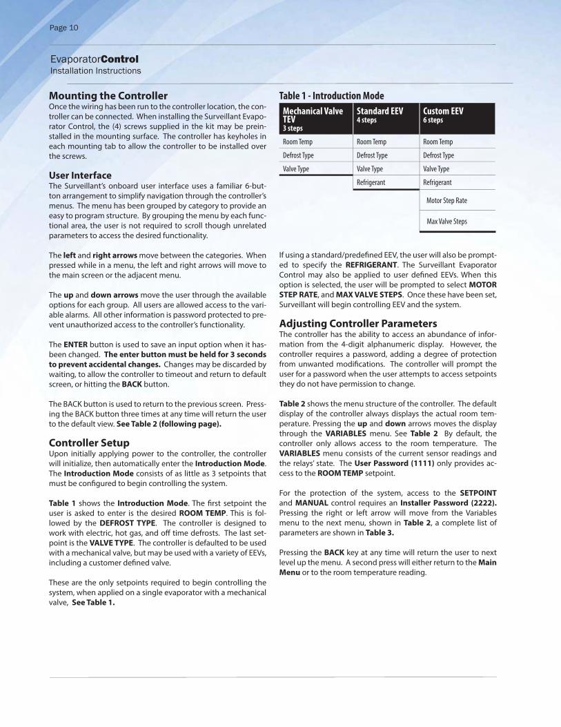
Controller SetupUpon initially applying power to the controller, the controller will initialize, then automatically enter the Introduction Mode. The Introduction Mode consists of as little as 3 setpoints that must be confi gured to begin controlling the system.
Table 1 shows the Introduction Mode. The fi rst setpoint the user is asked to enter is the desired ROOM TEMP. This is fol-lowed by the DEFROST TYPE. The controller is designed to work with electric, hot gas, and off time defrosts. The last set-point is the VALVE TYPE. The controller is defaulted to be used with a mechanical valve, but may be used with a variety of EEVs, including a customer defi ned valve.
These are the only setpoints required to begin controlling the system, when applied on a single evaporator with a mechanical valve, See Table 1.
Table 1 - Introduction Mode
Mechanical Valve TEV3 steps
Standard EEV4 steps
Custom EEV6 steps
Room Temp Room Temp Room Temp
Defrost Type Defrost Type Defrost Type
Valve Type Valve Type Valve Type
Refrigerant Refrigerant
Motor Step Rate
Max Valve Steps
If using a standard/predefi ned EEV, the user will also be prompt-ed to specify the REFRIGERANT. The Surveillant Evaporator Control may also be applied to user defi ned EEVs. When this option is selected, the user will be prompted to select MOTOR
STEP RATE, and MAX VALVE STEPS. Once these have been set, Surveillant will begin controlling EEV and the system.
Adjusting Controller ParametersThe controller has the ability to access an abundance of infor-mation from the 4-digit alphanumeric display. However, the controller requires a password, adding a degree of protection from unwanted modifi cations. The controller will prompt the user for a password when the user attempts to access setpoints they do not have permission to change.
Table 2 shows the menu structure of the controller. The default display of the controller always displays the actual room tem-perature. Pressing the up and down arrows moves the display through the VARIABLES menu. See Table 2 By default, the controller only allows access to the room temperature. The VARIABLES menu consists of the current sensor readings and the relays’ state. The User Password (1111) only provides ac-cess to the ROOM TEMP setpoint.
For the protection of the system, access to the SETPOINT and MANUAL control requires an Installer Password (2222). Pressing the right or left arrow will move from the Variables menu to the next menu, shown in Table 2, a complete list of parameters are shown in Table 3.
Pressing the BACK key at any time will return the user to next level up the menu. A second press will either return to the Main
Menu or to the room temperature reading.
EvaporatorControl Installation Instructions

Page 11
EvaporatorControl Installation Instructions
Menu Parameters:
MANUAL CONTROLMANUAL VALVECLEAR ALARMS
MANUAL COMPRESSOR RELAYMANUAL DEFROST RELAY
MANUAL FAN RELAYDHCP
FACTORY RESET
Menus:Variables Manual
(view only)
Non-adjustable
NO ALARMPRESSURE SENSOR
SUCTION TEMP SENSORAIR TEMP SENSOR
COIL TEMP SENSORAUX TEMP SENSOR
HIGH SUPERHEATLOW SUPERHEAT
HIGH AIR TEMPLOW AIR TEMP
EXCESS DEFROSTDEFR TERM ON TIME
DOOR SWITCHCOMMUNICATION ERROR
EXT ALARM
Alarms (view only)
ENTERENTER
ENTERENTER
Left and Right Arrows Use to move between Menus
Up Arrow and Down Arrow
Scroll through Menu Parameters
ENTERPress and hold ENTER for 3 seconds, when display begins blinking changes can be made
BACK Press BACK to return to the previous view.
ENTER Press and hold ENTER for 3 seconds to save change
To change settings:
To save setting changes:
To move through
controller menus:
To return to Main Menu:
Indicator lights Red light - critical alarm (system off)Yellow light - non-critical alarm (system running)Green light - compressor onGreen flashing - compressor waiting on timer to start/stop
ENTER
BACK
ROOM TEMPDEFROST TYPE
VALVE TYPEMOTOR STEP RATEMAX VALVE STEPS
SUPERHEATMAX OPERATING PRES
REFRIGERANTAUX TEMP MODE
AUX RELAY MODEDAC FAN
MIN COMP RUN TIMEMIN COMP OFF TIME
REFRIG FAN MODEDEFROST MODEDEFROSTS / DAY
1ST DEFROST DELAYDEFROST FAN STATE
DEFROST TERM TEMPDEFROST PARAMETER
DRAIN TIMECOMP RUN TIME
ELEC DEFROST MODEFAN DELAY TEMP
MAX FAN DELAY TIMEPUMP DOWN TIME
MULTI AIR TEMP CTRLMULTI EVAP COOL
MULTI EVAP DEFROSTMULTI EVAP SENSOR
HIGH TEMP ALARM OFFSETHIGH TEMP ALARM DELAY
LOW TEMP ALARM OFFSETLOW TEMP ALARM DELAY
DOOR ALARM DELAYDIG IN 1 MODEDIG IN 1 STATE
DIG IN 2 MODEDIG IN 2 STATE
DIG IN 3 MODEDIG IN 3 STATE
2ND ROOM TEMPSUCT PRES OFFSET
SUCT TEMP OFFSETAIR TEMP OFFSET
COIL TEMP OFFSETAUX TEMP OFFSET
TEMP UNITSAIR TEMP DIFF
EXTREME TEMP DIFF
Setpoints*
* The Setpoint paramenters shown in BOLD (Valve Type, Room Temp Setpoint and Defrost Mode) need to be set by the user prior to start up. The other Setpoint Parameters can also be adjusted, however the factory setpoints are generally correct for most applications.
The Setpoint parameters shown in ITALIC are only displayed when an EEV is used.
The Setpoint parameters shown in BOLD ITALIC are displayed for bonded controllers only.
ROOM TEMPCOIL TEMP
SYSTEM MODESUPERHEAT
SUCTION PRESSURE T1 SUCTION** TEMP
SATURATION TEMPVALVE % OPENT4 AUX** TEMP
COMPRESSOR RELAYDEFROST RELAY
FAN RELAYAUX RELAY
DIG 1 STATUSDIG 2 STATUSDIG 3 STATUS
IP OCTET 1IP OCTET 2IP OCTET 3IP OCTET 4
SUBNET MASK OCTET 1SUBNET MASK OCTET 2SUBNET MASK OCTET 3SUBNET MASK OCTET 4
FIRMWARE VERSION
Variables for DIG IN Mode
DIG IN MODE = DISABLEDDIG IN MODE = 2ND (ROOM) TEMP
DIG IN MODE = DOOR SWITCHDIG IN MODE = EXT ALARM
DIG IN MODE = SYSTEM OFFDIG IN MODE = DEFROST LOCKOUT
DIG IN MODE = DEFROST INTERLOCK
ENTER Press ENTER to go from parameter to value.To toggle beweendescription and value :
** T1 and T4 are parameters that can be set to various functions. The default for T1 is Suction Temp, the T4 is Coil Temp.
Table 2 - Navigation Through the Controller Menu and Menu Paramenters
Page 12
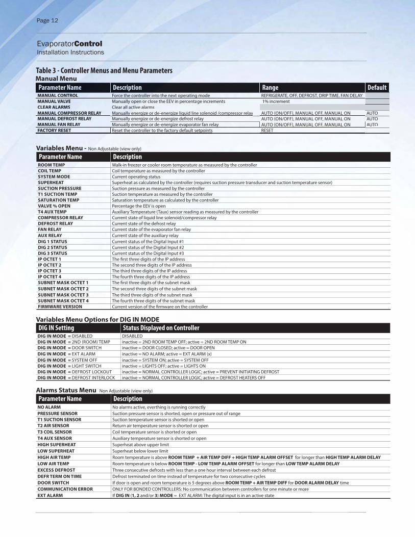
Table 3 - Controller Menus and Menu Parameters
Parameter Name DescriptionNO ALARM No alarms active, everthing is running correctlyPRESSURE SENSOR Suction pressure sensor is shorted, open or pressure out of rangeT1 SUCTION SENSOR Suction temperature sensor is shorted or openT2 AIR SENSOR Return air temperature sensor is shorted or openT3 COIL SENSOR Coil temperature sensor is shorted or openT4 AUX SENSOR Auxiliary temperature sensor is shorted or openHIGH SUPERHEAT Superheat above upper limitLOW SUPERHEAT Superheat below lower limitHIGH AIR TEMP Room temperature is above ROOM TEMP + AIR TEMP DIFF + HIGH TEMP ALARM OFFSET for longer than HIGH TEMP ALARM DELAY
LOW AIR TEMP Room temperature is below ROOM TEMP - LOW TEMP ALARM OFFSET for longer than LOW TEMP ALARM DELAY
EXCESS DEFROST Three consecutive defrosts with less than a one hour interval between each defrostDEFR TERM ON TIME Defrost terminated on time instead of temperature for two consecutive cyclesDOOR SWITCH If door is open and room temperature is 5 degrees above ROOM TEMP + AIR TEMP DIFF for DOOR ALARM DELAY timeCOMMUNICATION ERROR ONLY FOR BONDED CONTROLLERS: No communication between controllers for one minute or moreEXT ALARM If DIG IN (1, 2 and/or 3) MODE = EXT ALARM: The digital input is in an active state
Paramemeeteter r NaNaName Description Range DefaultMANM UAUAL COCOOOONTRNTRNTRNTROOOLOL ForForce ce thethe cocontrntrolloller rer er iiintinto to he nexe t operp ating ng modmodee REFRIGRIGERAERATETE, OFOFF, F, DEFDEFROSROST,T, DRIDRIP TP TIMEIME, F, FAN N DELDELAYAYMANMAN ALUAL VALVELV ManM ualua ly open on on oor cr closlose te the he EEVEEV inin pepercercenntage increments 1% incrementCLECL ARAR ALARMS Clear all activtivtivivi e ae alarlarmmsMAMMANMM UAL COOMPRMPRESSES OR RELAYY Mannnualuuaua ly yly ly ly energiize or de-energize liquid line solenoid /compressor relayy g g q p y AUTO (ON/OFF), MANUAL OFF, MANUAL ON AUTOMMANMANUALUAL DEDEFROFROST S RELRELRELRE AYAYAYA ManManManM uauauaually energize or de-energize defrost relay AUTO (ON/OFF), MANUAL OFF, MANUAL ON AUTOMANMANUALUAL FAFAN RRRRELAELAELAE YYYY ManManManually energize or de-energize evaporator fan relay AUTO (ON/OFF), MANUALAL OFO F, , MANM UAL ON AUTOFACACTORO Y RESSSETT RReset the controller to the factory default setpoino tsy RESET
Parameter Name DescriptionROOM TEMP Walk-in freezer or cooler room temperature as measured by the controllerCOIL TEMP Coil temperature as measured by the controllerSYSTEM MODE Current operating statusSUPERHEAT Superheat as calculated by the controller (requires suction pressure transducer and suction temperature sensor)SUCTION PRESSURE Suction pressure as measured by the controllerT1 SUCTION TEMP Suction temperature as measured by the controllerSATURATION TEMP Saturation temperature as calculated by the controllerVALVE % OPEN Percentage the EEV is openT4 AUX TEMP Auxiliary Temperature (Taux) sensor reading as measured by the controllerCOMPRESSOR RELAY Current state of liquid line solenoid/compressor relayDEFROST RELAY Current state of the defrost relayFAN RELAY Current state of the evaporator fan relayAUX RELAY Current state of the auxiliary relayDIG 1 STATUS Current status of the Digital Input #1DIG 2 STATUS Current status of the Digital Input #2DIG 3 STATUS Current status of the Digital Input #3IP OCTET 1 The fi rst three digits of the IP addressIP OCTET 2 The second three digits of the IP addressIP OCTET 3 The third three digits of the IP addressIP OCTET 4 The fourth three digits of the IP addressSUBNET MASK OCTET 1 The fi rst three digits of the subnet maskSUBNET MASK OCTET 2 The second three digits of the subnet maskSUBNET MASK OCTET 3 The third three digits of the subnet maskSUBNET MASK OCTET 4 The fourth three digits of the subnet maskFIRMWARE VERSION Current version of the fi rmware on the controller
Variables Menu - Non Adjustable (view only)
Alarms Status Menu Non Adjustable (view only)
Manual Menu
DIG IN Setting Status Displayed on ControllerDIG IN MODE = DISABLED DISABLEDDIG IN MODE = 2ND (ROOM) TEMP inactive = 2ND ROOM TEMP OFF; active = 2ND ROOM TEMP ONDIG IN MODE = DOOR SWITCH inactive = DOOR CLOSED; active = DOOR OPENDIG IN MODE = EXT ALARM inactive = NO ALARM; active = EXT ALARM (x)DIG IN MODE = SYSTEM OFF inactive = SYSTEM ON; active = SYSTEM OFFDIG IN MODE = LIGHT SWITCH inactive = LIGHTS OFF; active = LIGHTS ONDIG IN MODE = DEFROST LOCKOUT inactive = NORMAL CONTROLLER LOGIC; active = PREVENT INITIATING DEFROSTDIG IN MODE = DEFROST INTERLOCK inactive = NORMAL CONTROLLER LOGIC; active = DEFROST HEATERS OFF
Variables Menu Options for DIG IN MODE
EvaporatorControl Installation Instructions
Page 13
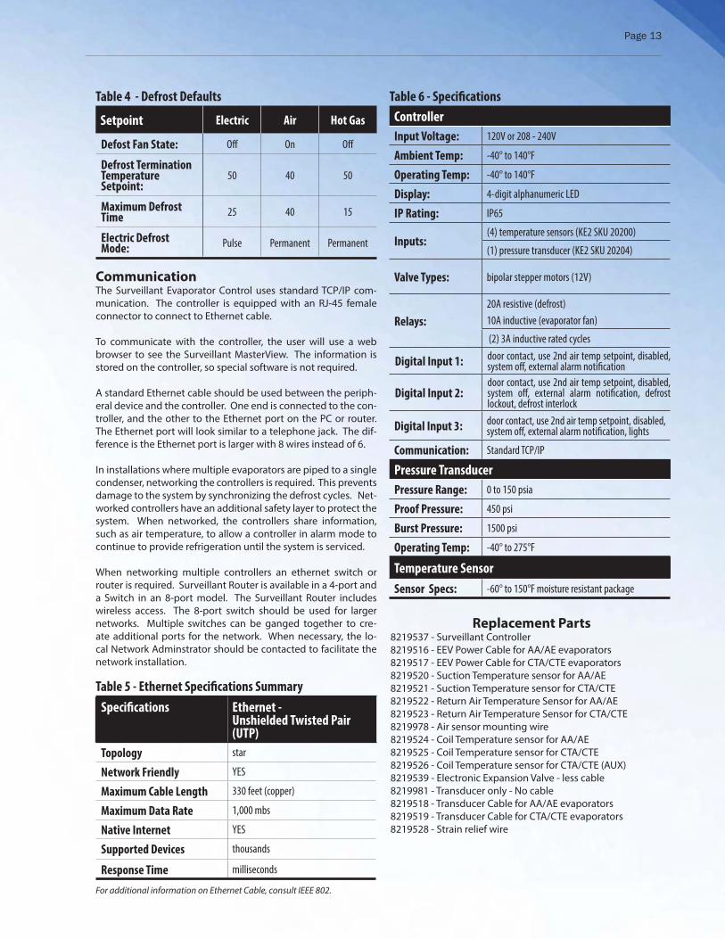
CommunicationThe Surveillant Evaporator Control uses standard TCP/IP com-munication. The controller is equipped with an RJ-45 female connector to connect to Ethernet cable.
To communicate with the controller, the user will use a web browser to see the Surveillant MasterView. The information is stored on the controller, so special software is not required.
A standard Ethernet cable should be used between the periph-eral device and the controller. One end is connected to the con-troller, and the other to the Ethernet port on the PC or router. The Ethernet port will look similar to a telephone jack. The dif-ference is the Ethernet port is larger with 8 wires instead of 6.
In installations where multiple evaporators are piped to a single condenser, networking the controllers is required. This prevents damage to the system by synchronizing the defrost cycles. Net-worked controllers have an additional safety layer to protect the system. When networked, the controllers share information, such as air temperature, to allow a controller in alarm mode to continue to provide refrigeration until the system is serviced.
When networking multiple controllers an ethernet switch or router is required. Surveillant Router is available in a 4-port and a Switch in an 8-port model. The Surveillant Router includes wireless access. The 8-port switch should be used for larger networks. Multiple switches can be ganged together to cre-ate additional ports for the network. When necessary, the lo-cal Network Adminstrator should be contacted to facilitate the network installation.
Table 5 - Ethernet Specifi cations Summary
Specifi cations Ethernet - Unshielded Twisted Pair (UTP)
Topology star
Network Friendly YES
Maximum Cable Length 330 feet (copper)
Maximum Data Rate 1,000 mbs
Native Internet YES
Supported Devices thousands
Response Time milliseconds
For additional information on Ethernet Cable, consult IEEE 802.
Table 4 - Defrost Defaults
Setpoint Electric Air Hot Gas
Defost Fan State: Off On Off
Defrost Termination Temperature Setpoint:
50 40 50
Maximum Defrost Time 25 40 15
Electric Defrost Mode: Pulse Permanent Permanent
Table 6 - Specifi cations
Controller
Input Voltage: 120V or 208 - 240V
Ambient Temp: -40° to 140°F
Operating Temp: -40° to 140°F
Display: 4-digit alphanumeric LED
IP Rating: IP65
Inputs:(4) temperature sensors (KE2 SKU 20200)
(1) pressure transducer (KE2 SKU 20204)
Valve Types: bipolar stepper motors (12V)
Relays:
20A resistive (defrost)10A inductive (evaporator fan)
(2) 3A inductive rated cycles
Digital Input 1: door contact, use 2nd air temp setpoint, disabled, system off , external alarm notifi cation
Digital Input 2:door contact, use 2nd air temp setpoint, disabled, system off , external alarm notifi cation, defrost lockout, defrost interlock
Digital Input 3: door contact, use 2nd air temp setpoint, disabled, system off , external alarm notifi cation, lights
Communication: Standard TCP/IP
Pressure Transducer
Pressure Range: 0 to 150 psia
Proof Pressure: 450 psi
Burst Pressure: 1500 psi
Operating Temp: -40° to 275°F
Temperature Sensor
Sensor Specs: -60° to 150°F moisture resistant package
Replacement Parts8219537 - Surveillant Controller8219516 - EEV Power Cable for AA/AE evaporators8219517 - EEV Power Cable for CTA/CTE evaporators8219520 - Suction Temperature sensor for AA/AE 8219521 - Suction Temperature sensor for CTA/CTE 8219522 - Return Air Temperature Sensor for AA/AE 8219523 - Return Air Temperature Sensor for CTA/CTE8219978 - Air sensor mounting wire8219524 - Coil Temperature sensor for AA/AE8219525 - Coil Temperature sensor for CTA/CTE8219526 - Coil Temperature sensor for CTA/CTE (AUX)8219539 - Electronic Expansion Valve - less cable8219981 - Transducer only - No cable8219518 - Transducer Cable for AA/AE evaporators8219519 - Transducer Cable for CTA/CTE evaporators8219528 - Strain relief wire

Page 14
Parameter Name Description
ROOM TEMP Room temperature to be maintained
DEFROST TYPEMethod of defrost used on the evaporator coil: Electric, Air, Hot Gas with Liquid Line Solenoid/Compressor relay off , Hot Gas with Liquid Line Solenoid/compressor relay on
VALVE TYPE Type of valve used on the system: mechanical, pre-confi gured electric, custom EEV confi guration
Cust
om
EEV
on
ly MOTOR STEP RATE If VALVE TYPE = CUSTOM: The motor speed setting in number of steps per second
MAX VALVE STEPS If VALVE TYPE = CUSTOM: The total number of steps required to move the valve from closed to fully open
SUPERHEAT The superheat value that the controller will maintain, (not applicable if VALVE TYPE = MECHANICAL)
MAX OPERATING PRES The maximum allowable suction pressure, (not applicable if VALVE TYPE = MECHANICAL)
REFRIGERANT The type of refrigerant used in the refrigeration system
AUX TEMP MODE Confi guration mode of the auxiliary temperature sensor
AUX RELAY MODE Confi guration mode of the auxiliary relay.
DAC FAN Provides 0-10V DC signal to control variable speed
MIN COMP RUN TIME Minimum amount of time the liquid line solenoid/compressor relay must remain on after it is energized
MIN COMP OFF TIME Minimum amount of time the liquid line solenoid/compressor relay must remain off before it can be energized again.
REFRIG FAN MODE Fan operation while in refrigeration mode
DEFROST MODE The method the controller uses to determine when to initiate a defrost.
DEFROSTS / DAY If DEFROST MODE = SCHEDULED: The number of evenly spaced defrosts per day the controller will initiate.
1ST DEFROST DELAY If DEFROST MODE = SCHEDULED: The amount of time from controller power up until the fi rst defrost is initiated.
DEFROST FAN STATE Whether or not to run the evaporator fans during defrost
DEFROST TERM TEMP The temperature the coil sensor(s) must exceed in order to terminate defrost. The defrost relay is de-energized at this point.
DEFROST PARAMETER The maximum amount of time the defrost relay will be energized.
DRAIN TIME Time to be in drain mode (drip time)
COMP RUN TIME If DEFROST MODE = RUN TIME: The amount of time liquid line solenoid/compressor relay is energized before the next defrost is initiated.
ELEC DEFROST MODE If DEFROST TYPE = ELEC: Whether to leave the defrost relay energized during the defrost cycle or to utilize advanced defrost algorithm.
FAN DELAY TEMP After defrost, the coil sensor reading must fall below this temperature set point in order for the controller to resume normal fan operation.
MAX FAN DELAY TIME Maximum amount of time after defrost to resume normal fan operation.
PUMP DOWN TIME Minimum amount of time between de-energizing the liquid line solenoid/compressor relay and energizing the defrost relay.
MULTI AIR TEMP CTRL Select control method to use with multiple room temperature sensors
Bon
ded
Con
trol
lers
O
nly
MULTI EVAP COOL Select type of multi evaporator control - options are synchronous or independent
MULTI EVAP DEFROST Select whether to have all bonded controllers initiate defrost mode at the same time or independently.
MULTI EVAP SENSOR Select whether or not to share room temperature, coil temperature and suction pressure sensor data with bonded controllers.
HIGH TEMP ALARM OFFSET The number of degrees above ROOM TEMP for a HIGH TEMP ALARM condition.
HIGH TEMP ALARM DELAY Minutes the room temperature must remain above ROOM TEMP + HIGH TEMP ALARM OFFSET before issuing a HIGH TEMP ALARM
LOW TEMP ALARM OFFSET The number of degrees below ROOM TEMP for a LOW TEMP ALARM condition.
LOW TEMP ALARM DELAY Minutes the room temperature must remain below ROOM TEMP - LOW TEMP ALARM OFFSET before issuing a LOW TEMP ALARM
DOOR ALARM DELAYIf DIG IN (1, 2 and/or 3) MODE = DOOR SWITCH: The amount of time, in minutes, before an alarm condition is initiated if door is open and room temperature is 5 degrees above ROOM TEMP + AIR TEMP DIFF
DIG IN 1 MODE Sets the function of the digital input
DIG IN 1 STATE Sets whether the switch activates when opened or closed
DIG IN 2 MODE Sets the function of the digital input
DIG IN 2 STATE Sets whether the switch activates when opened or closed
DIG IN 3 MODE Sets the function of the digital input
DIG IN 3 STATE Sets whether the switch activates when opened or closed
2ND ROOM TEMP If DIG IN (1, 2 and/or 3) MODE = 2ND ROOM TEMP: This value becomes the ROOM TEMP setpoint when the digital input is active
SUCT PRES OFFSET An off set added or subtracted from the suction line pressure transducer reading, if needed
SUCT TEMP OFFSET An off set added or subtracted from the suction temperature sensor reading, if needed
AIR TEMP OFFSET An off set added or subtracted from the room temperature sensor reading, if needed
COIL TEMP OFFSET An off set added or subtracted from the coil temperature sensor reading, if needed
AUX TEMP OFFSET An off set added or subtracted from the auxiliary temperature sensor reading, if needed
TEMP UNITS Units for temperature’s display in °F or °C
AIR TEMP DIFF The number of degrees above ROOM TEMP before the controller will go into REFRIGERATION mode
EXTREME TEMP DIFF ADVANCED TOPIC: Call Applications Engineering for assistance
Setpoints Menu
EvaporatorControl Installation Instructions

Page 15
EvaporatorControl Installation Instructions
Range Default Current
-50°F to 90°F -10°F
ELEC, AIR, HOT GAS COMP ON, HOT GAS COMP OFFELEC
MECHANICAL, SER/SEI 1 TO 20, SER B TO L, SEI 30, SEI 50, SEH, ETS12 TO 50, ETS100, ETS250/400, KV, CAREL, CUSTOM;
MECHANICAL
30 to 400 steps/second 200 steps
200 to 6400 steps 1600 steps
5°F to 30°F 8°F
10 to 150 psig 150 psig
404A, R507, 407A, 407C, 422A, 422D, 134A, R22, R717, 438A, 408A, 409A, 410A, R744 404A
DISABLED, MONITOR, 2ND AIR TEMP, 2ND COIL TEMP DISABLED
ALARM RELAY, 2 SPEED FAN CTL, 2ND COMP RELAY, 2ND FAN RELAY, 2ND DEFR RELAY, LIGHT RELAY
ALARM RELAY
-100% to 100% 0.000 (Off )
0 to 15 minutes 2 minutes
0 to 15 minutes 5 minutes
ON WITH COMPRESSOR, PERMANENT, CYCLE ON WITH COMPRESSOR
DEMAND, SCHEDULED, RUN TIME DEMAND
0 to 8 5
0 to 240 minutes 120 minutes
ON/OFF OFF if DEFROST TYPE = ELEC, HOT GAS COMP ON, HOT GAS COMP OFFON if DEFROST TYPE = AIR
35°F to 90°F 50°F if DEFROST TYPE = ELEC, HOT GAS COMP ON, HOT GAS COMP OFF40°F if DEFROST TYPE = AIR
0 to 90 minutes25 minutes if DEFROST TYPE = ELEC10 minutes if DEFROST TYPE = HOT GAS COMP ON, HOT GAS COMP OFF40 minutes if DEFROST TYPE = AIR
0 to 15 minutes 2 minutes
0 to 24 hours 6 hours
PULSE, PERMANENT PULSE
-40°F to 35°F 20°F
0 to 20 minutes 2 minutes
0 to 10 minutes 0 minutes
AVERAGE, WARMEST WARMEST
SYNC, INDEPENDENT SYNC
SYNC, INDEPENDENT SYNC
SHARED, NOT SHARED SHARED
0°F to 99.9°F 10°F
0 to 120 minutes 60 minutes
0°F to 20°F 4°F
0 to 30 minutes 10 minutes
0 to 180 minutes 30 minutes
DISABLED, 2ND ROOM TEMP, DOOR SWITCH, EXT ALARM, SYSTEM OFF DOOR
OPEN, CLOSED CLOSED
DISABLED, 2ND ROOM TEMP, DOOR SWITCH, EXT ALARM, SYSTEM OFF, DEFR INTER-LOCK
DISABLED
OPEN, CLOSED CLOSED
DISABLED, 2ND ROOM TEMP, DOOR SWITCH, EXT ALARM, SYSTEM OFF, LIGHT SWITCH, CAMERA SWITCH
DISABLED
OPEN, CLOSED CLOSED
-50°F to 90°F -50°F
-5.0 to 5.0 psig 0.0 psig
-5.0°F to 5.0°F 0.0°F
-5.0°F to 5.0°F 0.0°F
-5.0°F to 5.0°F 0.0°F
-5.0°F to 5.0°F 0.0°F
FAHRENHEIT/CELSIUS FAHRENHEIT
0°F to 5°F 1°F

Heat Transfer Products Group. 201 Thomas French Drive • Scottsboro AL. 35769
Ph: 256-259-7400 • www.htpgusa.com