hsb3dprinting - hsbcad © 2015 hsbcad rp 02-apr-2015 page 1 of 16 overview with the hsb3dprinting...
TRANSCRIPT

hsb3DPrinting
© 2015 hsbcad RP 02-Apr-2015 Page 1 of 16
OVERVIEW
With the hsb3dPrinting add-in for Revit you can print Revit models on a large scale by splitting up objects
in Revit and adding connections to them.
The hsb3dPrinting tab in the Ribbon shows the workflow of turning a Revit model into batches of .stl files,
these batches contain FreeForms with connections.
The workflow is:
1. In the settings you set the scale, the splitting, the labelling and the connections.
2. Create SplittableSolids over Revit objects, these SplittableSolids can be divided into FreeForms.
3. Label the Freeforms
4. Add connections
5. Stack the FreeForms into batches
6. Export the batches to .stl files
Before you start make sure you load the following family’s in your drawing:
These families can be found in the support folder in the install file path.

hsb3DPrinting
© 2015 hsbcad RP 02-Apr-2015 Page 2 of 16
EXPLANATION OF THE INDIVIDUAL COMMAND IN SAME ORDER AS THE
HSB3DPRINTING TAB:
SETTINGS
In the settings you can set the 3d printing settings for all individual Auto commands and the commands in
the ''hsb Generate’’ tab.
Make sure you set the scale and your printer dimensions, before you make FreeForms.
HSBGENERATE
Create FreeForms, do splitting, connections, labelling and stacking automatic with the values from the
settings
Ceate FreeForms, do splitting, connections, labelling and stacking automatic with the values from the
settings from a linked drawing
PRINTPARTS
Create SplittableSolids from Walls, floors and roofs and split them in to Freeforms from the values in the
settings.
Create SplittableSolids with a non-splitted Freeform from Walls, floors and roofs.

hsb3DPrinting
© 2015 hsbcad RP 02-Apr-2015 Page 3 of 16
Create Freeforms from Revit Parts.
Create a SplittableSolid and a non-splitted Freeforms from any object.
Create SplittableSolids from Walls, floors and roofs and split them in to Freeforms from the values in the
settings from a linked drawing.
Create SplittableSolids with a non splitted Freeform from Walls, floors and roofs from a linked drawing.
In Edit mode you will go to the ucs of the element where you can split up a SplittableSolid into FreeForms
by drawing or modifying modellines
Delete only Freeforms and SplittableSolids.
Checks if any FreeForm exceeds the maximum sizes from the settings or if a split goes trough an opening.
LABELS
Labels Freeforms of selected SplittableSolids.
Labels selected connections.
Creates views of the SplittableSolids and 1 view with all Freeforms and export them to DWF.

hsb3DPrinting
© 2015 hsbcad RP 02-Apr-2015 Page 4 of 16
Explode the FreeForms in the view.
CONNECTIONS
Select PrintParts and add connections from the settings.
Manual select connections and add them to FreeForms.
STACK
Auto select FreeForms and stack them in seperate 3D views with offsets from the settings.
Rotate a Stacked FreeFrom.
EXPORT
Export views or pick elements to be exported to STL format.
MODIFY
This will make you go into Edit Mode

hsb3DPrinting
© 2015 hsbcad RP 02-Apr-2015 Page 5 of 16
This will switch your view to the ucs of the element
Rotate a Stacked FreeFrom.
Checks if any FreeForm exceeds the maximum sizes from the settings or if a split goes trough an opening.
EDIT MODE
Cancel and exit Edit Mode
Finish and exit Edit Mode
Add Modellines to divide the SplittableSolid in FreeForms
TERMINOLOGY LIST
SPLITTABLESOLIDS AND FREEFORMS:
To print objects in Revit we add our own object over a Revit object, This is a SplittableSolid (Generic
Model), this SplittableSolid can be divided into FreeForms (Structural Framing) as an example see the Wall
below:

hsb3DPrinting
© 2015 hsbcad RP 02-Apr-2015 Page 6 of 16
The Revit Wall
The SplittableSolid of the Wall
The FreeForms of the SplittableSolids

hsb3DPrinting
© 2015 hsbcad RP 02-Apr-2015 Page 7 of 16
Note: SplittableSolids that are not split have 1 FreeForm

hsb3DPrinting
© 2015 hsbcad RP 02-Apr-2015 Page 8 of 16
LABELLING:
Adds a Label to the FreeForms as a family (Generic Model) and as a propertie of the FreeForm

hsb3DPrinting
© 2015 hsbcad RP 02-Apr-2015 Page 9 of 16
CONNECTIONS:
You can edit the connection by selecting the family-instance that adds the connection. It is placed in the
center of the 2 faces that connect.
When you select it you can change the edit type parameters of the family to change the
connections, also there are some instance parameters witch will change the connections:
hsb3DPrinting
© 2015 hsbcad RP 02-Apr-2015 Page 10 of 16
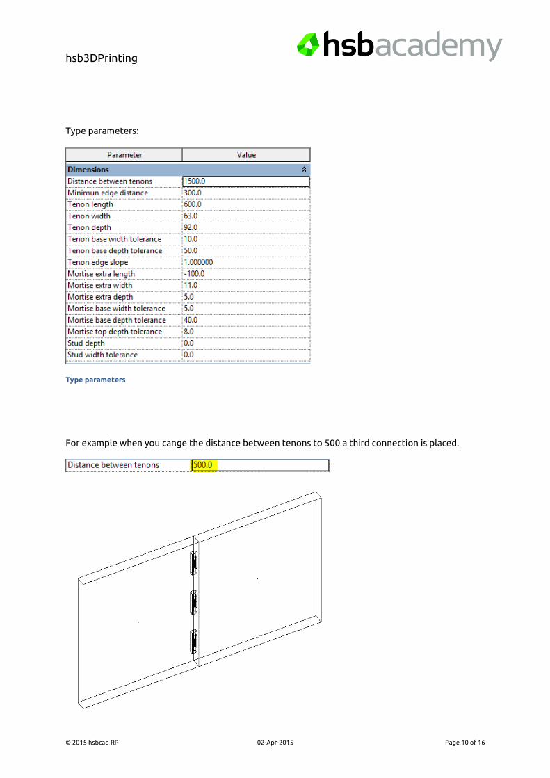
Type parameters:
Type parameters
For example when you cange the distance between tenons to 500 a third connection is placed.

hsb3DPrinting
© 2015 hsbcad RP 02-Apr-2015 Page 11 of 16
These are all Parameters in an example of 2 walls:
Top View

hsb3DPrinting
© 2015 hsbcad RP 02-Apr-2015 Page 12 of 16
Side view

hsb3DPrinting
© 2015 hsbcad RP 02-Apr-2015 Page 13 of 16
Side view 1 connection

hsb3DPrinting
© 2015 hsbcad RP 02-Apr-2015 Page 14 of 16
Also there are some instance Parameters:
Instance Parameters
Flip: Flips the mortise and tennon
Use tolerance From Inside Face: tick to use Tolerance from inside face propertie
Tolerance from inside face: Connection is set with a distance from inside face.

hsb3DPrinting
© 2015 hsbcad RP 02-Apr-2015 Page 15 of 16
Top View
STACKING:
This will make Printviews with the FreeForms stacked according to the settings.

hsb3DPrinting
© 2015 hsbcad RP 02-Apr-2015 Page 16 of 16
3d View