hs-2800 - full compass connector pin assignment ... hs-2800 is light weight, portable and powerful...
TRANSCRIPT
12-CHANNEL HD/SD HAND CARRIED STUDIO
HS-2800
Quick Start Guide
Feb-25.2013
P/N: G082060639B1

1
Table of Contents
Warnings & Precautions .................................................................................................................... 2
Warranty ............................................................................................................................................ 3
Disposal ............................................................................................................................................. 3
What’s in the box? ............................................................................................................................. 3
Overview ............................................................................................................................................ 4
Features ............................................................................................................................................. 4
Connections & Controls ..................................................................................................................... 5
Keyboard ...................................................................................................................................... 5
Rear Panel ................................................................................................................................... 9
Intercom & Monitor Control Panel .................................................................................................... 12
Transition Effects ............................................................................................................................. 17
Setting SDI Embedded Audio .......................................................................................................... 18
MENU Function Setting ................................................................................................................... 19
Firmware Update Procedure ............................................................................................................ 24
LOGOS Setup .................................................................................................................................. 31
Tally Connector Pin Assignment ...................................................................................................... 33
GPI OUT Pin Assignment ................................................................................................................ 35
Dimension ........................................................................................................................................ 36
Specification ..................................................................................................................................... 37
HS-2800 Specification................................................................................................................ 37
ITC-150 (Intercom) Specification ............................................................................................... 38
ITC-100SL Specification ............................................................................................................ 38
TLM-170H Specification ............................................................................................................. 38
Service & Support ............................................................................................................................ 39
2
Warnings & Precautions
1. Read all of these warnings and save them for later reference.
2. Follow all warnings and instructions marked on this unit.
3. Unplug this unit from the wall outlet before cleaning. Do not use liquid or aerosol cleaners. Use a damp cloth for
cleaning.
4. Do not use this unit in or near water.
5. Do not place this unit on an unstable cart, stand, or table. The unit may fall, causing serious damage.
6. Slots and openings on the cabinet top, back, and bottom are provided for ventilation. To ensure safe and
reliable operation of this unit, and to protect it from overheating, do not block or cover these openings. Do not
place this unit on a bed, sofa, rug, or similar surface, as the ventilation openings on the bottom of the cabinet
will be blocked. This unit should never be placed near or over a heat register or radiator. This unit should not be
placed in a built-in installation unless proper ventilation is provided.
7. This product should only be operated from the type of power source indicated on the marking label of the AC
adapter. If you are not sure of the type of power available, consult your Datavideo dealer or your local power
company.
8. Do not allow anything to rest on the power cord. Do not locate this unit where the power cord will be walked on,
rolled over, or otherwise stressed.
9. If an extension cord must be used with this unit, make sure that the total of the ampere ratings on the products
plugged into the extension cord do not exceed the extension cord’s rating.
10. Make sure that the total amperes of all the units that are plugged into a single wall outlet do not exceed 15
amperes.
11. Never push objects of any kind into this unit through the cabinet ventilation slots, as they may touch dangerous
voltage points or short out parts that could result in risk of fire or electric shock. Never spill liquid of any kind
onto or into this unit.
12. Except as specifically explained elsewhere in this manual, do not attempt to service this product yourself.
Opening or removing covers that are marked “Do Not Remove” may expose you to dangerous voltage points or
other risks, and will void your warranty. Refer all service issues to qualified service personnel.
13. Unplug this product from the wall outlet and refer to qualified service personnel under the following conditions:
a. When the power cord is damaged or frayed;
b. When liquid has spilled into the unit;
c. When the product has been exposed to rain or water;
d. When the product does not operate normally under normal operating conditions. Adjust only those
controls that are covered by the operating instructions in this manual; improper adjustment of other
controls may result in damage to the unit and may often require extensive work by a qualified technician
to restore the unit to normal operation;
e. When the product has been dropped or the cabinet has been damaged;
f. When the product exhibits a distinct change in performance, indicating a need for service.

3
Warranty
Standard Warranty Datavideo equipment is guaranteed against any manufacturing defects for one year from the date of purchase. The original purchase invoice or other documentary evidence should be supplied at the time of any request for
repair under warranty. Damage caused by accident, misuse, unauthorized repairs, sand, grit or water is not covered by this warranty. All mail or transportation costs including insurance are at the expense of the owner. All other claims of any nature are not covered. Cables & batteries are not covered under warranty. Warranty only valid within the country or region of purchase. Your statutory rights are not affected.
Two Year Warranty All Datavideo products purchased after 01-Oct.-2008 qualify for a free one year extension to the standard
Warranty, providing the product is registered with Datavideo within 30 days of purchase. For information on how to register please visit www.datavideo-tek.com or contact your local Datavideo office or authorized Distributors
Certain parts with limited lifetime expectancy such as LCD Panels, DVD Drives, Hard Drives are only covered for the first 10,000 hours, or 1 year (whichever comes first).
Any second year warranty claims must be made to your local Datavideo office or one of its authorized Distributors before the extended warranty expires.
Disposal For EU Customers only - WEEE Marking. This symbol on the product indicates that it will not be treated as household waste. It must be handed over to the applicable take-back scheme for the recycling of electrical and electronic equipment. For more detailed information about the recycling of this product, please contact your local Datavideo office.
What’s in the box? 1 x Gooseneck Microphone
4 x Headphone
4 x ITC-100SL
1 x Tally LED TD-1 with Black Velcro 36cm
4 x CB-3 XLR Cable + CON 20M
1 x AC Cord
1 x Switching adapter DC12V / 10A
4 x 3.5Ø earphone (M) to earphone (F) L: 17cm
1 x USB Light
1 x HS-2800 Instruction Manual
4
Overview
The HS-2800 is an 8 channel 10-bit 1920 x 1080i & cost-effective, broadcast-quality mobile hand carry switcher. Featuring 8 digital, it is designed for live events and TV programs that need to blend a variety of video and audio sources. HS-2800 is light weight, portable and powerful features for mobile switcher solution. As a complete AV package, the HS-2800 HD mobile studio enables users to switch seamlessly between video and audio sources and blend high-quality digital content on the fly. Advanced features include a 17.3-inch multi-image video monitor which displays multiple sources, as well as preview and program. The system is equipped with an eight way intercom system and is supplied with four belt packs for effective communication between the whole production crew. The HS-2800 is ideal for TV and video professionals working in outside broadcast or temporary video studios, such as theatres or conference centres. The HS2800 is also a great value solution for the worship, education and AV market.
Features
Supports 8 HD or SD Inputs in a variety of configurations:
HD Mode
- 8 HD-SDI - 6 HD-SDI + 2 HDMI
SD Mode
- 8 SD-SDI - 6 SDI +2 HDMI
2 SDI Outputs assignable to AUX, Program (PGM), Preview (PVW) or PGM clean - Built-in SD down-scaler on CH-2, CH3 SDI output
1 HDMI outputs for multi view monitoring
Audio I/O
- Input: 4 analogue balanced XLR - Output: 2 analogue balanced XLR. Supports embedded audio SDI output from 4-CH XLR Audio
input
Two DSK, supports Key and Fill
Cut, Mix and Wipe with borders
Clock on screen
Countdown counter on multi screen
Two PIP displays with user-defined borders
Tally, GPI interface and RJ45 for firmware upgrade
DC 12V operation voltage, available for mobile use
5
4
1314
15
16
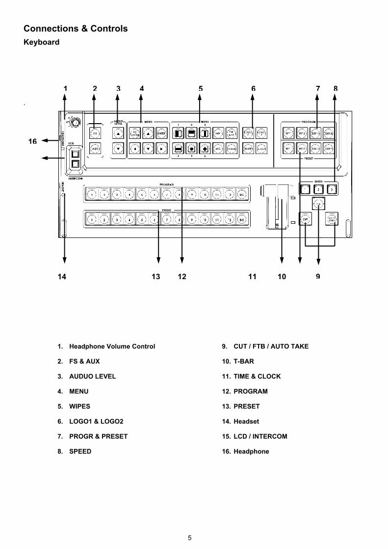
Connections & Controls Keyboard
`
8
12 9
763 51 2
1011
1. Headphone Volume Control
2. FS & AUX
3. AUDUO LEVEL
4. MENU
5. WIPES
6. LOGO1 & LOGO2
7. PROGR & PRESET
8. SPEED
9. CUT / FTB / AUTO TAKE
10. T-BAR
11. TIME & CLOCK
12. PROGRAM
13. PRESET
14. Headset
15. LCD / INTERCOM
16. Headphone

6
1. Headphone Volume Control
Controls Headphone or Headset volume level.
Use the Headphone section to accurately monitor any of the sources (LCD or
INTERCOM).
2. FS & AUX
FS Load frame by PC remote control tool (SEConfig) to RESET(Ch1~12), and then push FS key to take.
FS button is designed to perform Frame Still=Frame Store feature. A picture that can be used as background in a live video.
To set the FS, first press and hold the FS button ⇨ then the CH buttons, 1~12
(preset box) will turn RED ⇨ pick the desire CH which user wants to have a
background picture on.
AUX There are three SDI outputs at the rear of HS-2800 and one of them can be assigned by the user to be AUX-out in order to have a clean source (the video input signal which only bypassing the HS-2800 to the recorder, without any further effects on HS-2800, for effects on a, say a PC.)
The AUX feature can be set under Manual Setting ⇨Output Mode ⇨ assign one
of the three outputs as AUX. Then, under AUX Setting, user can pick the prefer type of video source from one of the connected camera.
3. AUDIO LEVEL
Setting the control audio levels on, press PRESET and then press AUDIO LEVELButton for Main audio output mix.
4. MENU
PC Control button is for PC remote control. Press the up, down, left, right arrow button move to another control, and ENTER button to confirm the setting.
5. WIPES
Wipe with border 6+2 options (changeable)
6. LOGO1 & LOGO2
Select SE-2000 Logo1, Logo2 Functions on the screen.

7
7. PROGR & PRESET
Picture In Picture can be set up in one of four preset positions, or manually moved to any position on the screen. It is possible to overlay titles from external signal in 2 ways, i.e. via Luma Keying or via Video + a-channel. The input signals used for the titles must be the same format as the basic output mode (HD or SD). It is prohibited to apply SD titles signal when the HD is the basic format. It is necessary to meet the following condition to realize 2 DSK channels: DSK1 Preview DSK1 Program (titles) DSK2 Preview DSK2 Program(titles)
8. SPEED
Selectable of three different speeds for transition effect.
9. CUT
Change the main/sub source immediately.
FTB
Fade to Black is performed upon FTB button stroke only in the Program Channel. The Button is lights with red color in this case. The previously pressed button of a signal source for Program Line stays with light on. There is FTB indication multi screen nearby the Program window. A repeated button stroke will escape the mode. When the mode is active, there is Black Field in the Program, but signal switching is still functional, i.e. it is possible to replace the signal at the Program output, and there will be a selected source when the FTB is deactivated.
AUTO TAKE
Take the effect by auto speed.
10. T-Bar
The T-Bar is used to carry out a manual transition such as a wipe, fade, mix or key. When it has travelled as far as it can go the transition is complete. For more information, see Calibrating the T-bar. If you don’t finish calibrating step, the T-Bar may cause incorrect results.
11. TIME & CLOCK
Select HS-2800 TIMER or CLOCK Functions on the screen.
12. PROGRAM
Used to select which of the 12 video input channels or background or color bar is
sent to the PROGRAM video output.
8
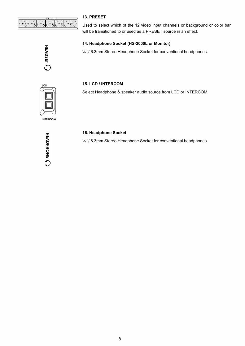
13. PRESET
Used to select which of the 12 video input channels or background or color bar
will be transitioned to or used as a PRESET source in an effect.
14. Headphone Socket (HS-2000L or Monitor)
¼ “/ 6.3mm Stereo Headphone Socket for conventional headphones.
15. LCD / INTERCOM
Select Headphone & speaker audio source from LCD or INTERCOM.
16. Headphone Socket
¼ “/ 6.3mm Stereo Headphone Socket for conventional headphones.

9
Rear Panel
1 2 3 4 5 6
7
1. HD- SDI IN / HDMI IN (12CH)
2. HD- SDI OUT / HDMI OUT / REMOTE CONTROL / CONSOLE
3. ALLY OUT
4. GPI
5. RS-422
6. AUDIO IN
7. MONITOR HDMI IN
8. POWER SWITCH
9. DC IN
10. MONITOR F/W Upgrade
11. TO BELTPACK
810 911
10
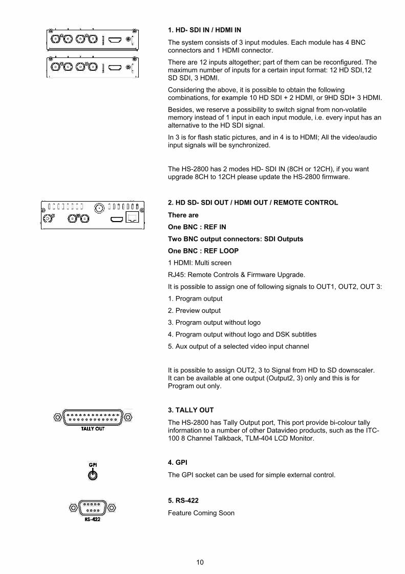
1. HD- SDI IN / HDMI IN
The system consists of 3 input modules. Each module has 4 BNC connectors and 1 HDMI connector.
There are 12 inputs altogether; part of them can be reconfigured. The maximum number of inputs for a certain input format: 12 HD SDI,12 SD SDI, 3 HDMI.
Considering the above, it is possible to obtain the following combinations, for example 10 HD SDI + 2 HDMI, or 9HD SDI+ 3 HDMI.
Besides, we reserve a possibility to switch signal from non-volatile memory instead of 1 input in each input module, i.e. every input has an alternative to the HD SDI signal.
In 3 is for flash static pictures, and in 4 is to HDMI; All the video/audio input signals will be synchronized.
The HS-2800 has 2 modes HD- SDI IN (8CH or 12CH), if you want upgrade 8CH to 12CH please update the HS-2800 firmware.
2. HD SD- SDI OUT / HDMI OUT / REMOTE CONTROL
There are
One BNC : REF IN
Two BNC output connectors: SDI Outputs
One BNC : REF LOOP
1 HDMI: Multi screen
RJ45: Remote Controls & Firmware Upgrade.
It is possible to assign one of following signals to OUT1, OUT2, OUT 3:
1. Program output
2. Preview output
3. Program output without logo
4. Program output without logo and DSK subtitles
5. Aux output of a selected video input channel
It is possible to assign OUT2, 3 to Signal from HD to SD downscaler. It can be available at one output (Output2, 3) only and this is for Program out only.
3. TALLY OUT
The HS-2800 has Tally Output port, This port provide bi-colour tally information to a number of other Datavideo products, such as the ITC-100 8 Channel Talkback, TLM-404 LCD Monitor.
4. GPI
The GPI socket can be used for simple external control.
5. RS-422
Feature Coming Soon

11
6. AUDIO IN
Supports four channels XLR Balanced Audio Input.
7. MONITOR HDMI IN
The HS-2800 provides a useful connection for confidence monitoring of HDMI sources on location.
8. POWER SWITCH
Switches the power On / Off.
9. DC IN
DC in socket connect the supplied 12V PSU to this socket. The connection can be secured by screwing the outer fastening ring of the DC In plug to the socket.
10. MONITOR F/W Upgrade
Socket is for monitor F/W upgrade.
11. TO BELTPACK (For Intercom)
Channel Input / Output XLR Sockets
Each of the 8 channels has an XLR connector that carries bi-directional signals between the ITC-150 and ITC-100SL. All connections are contained within the one cable.
12
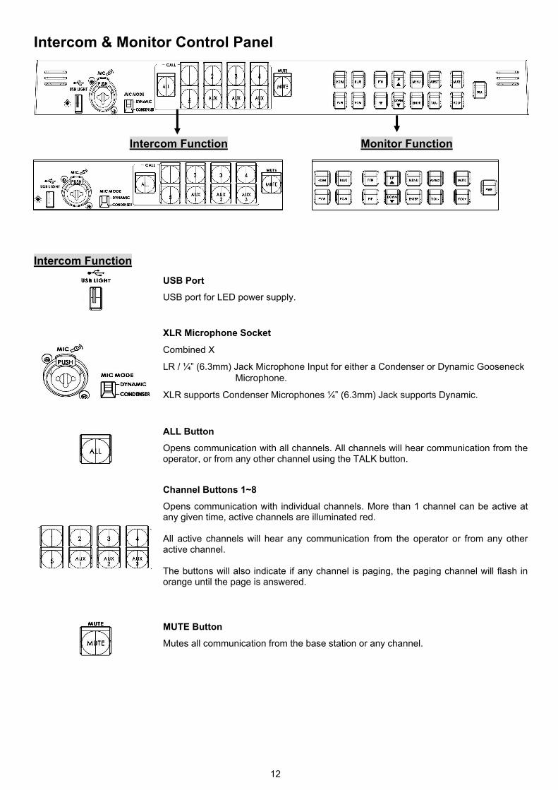
Intercom & Monitor Control Panel
Intercom Function Monitor Function
Intercom Function
USB Port
USB port for LED power supply.
XLR Microphone Socket
Combined X
LR / ¼” (6.3mm) Jack Microphone Input for either a Condenser or Dynamic Gooseneck Microphone.
XLR supports Condenser Microphones ¼” (6.3mm) Jack supports Dynamic.
ALL Button
Opens communication with all channels. All channels will hear communication from the operator, or from any other channel using the TALK button.
Channel Buttons 1~8
Opens communication with individual channels. More than 1 channel can be active at any given time, active channels are illuminated red. All active channels will hear any communication from the operator or from any other active channel. The buttons will also indicate if any channel is paging, the paging channel will flash in orange until the page is answered.
MUTE Button
Mutes all communication from the base station or any channel.
13
Monitor Function
HDMI, PREVIEW, PROGRAM
Select the type of input you are using - HDMI, PREVIEW, PROGRAM.
The active input will be indicated by a red LED on the Source Button.
When you push the ‘’HDMI’’ button, you select the 17.3" display from the HDMI source input of Rear Panel; It's a full screen display.
When you push the ‘’PREVIEW’’ button, then you go back to show multi-view from the other SDI inputs. So you can switch back & forth between HDMI & Preview.
BLUE
Press this button to eliminate the red and green component of input signals. Only the blue component of an input is displayed on the screen.
PATTERN
Press the PATTERN Key to activate the colour bar.
PIP
The PIP Feature Setting Menu allows you to adjust the appearance of the picture in picture. The position, size, main source and sub source can be set in the menus.
Menu Navigation Buttons
Display and navigate the set up menus - See Menu Options for more details
Down Button also switches the Safe Area Mask On / Off
UP Button also switches the 4:3 Mask On / Off - (only available in 16:10 modes)
Mute Button
Mutes the audio from the internal speakers or headphone socket.
Volume Control & Audio Meter
Adjusts the speaker / headphone volume up / down.
Aspect Ratio Button
Sets the Aspect Ratio to 16:10 / 4:3
PWR
Switches the TLM-170 Power ON / OFF.
14
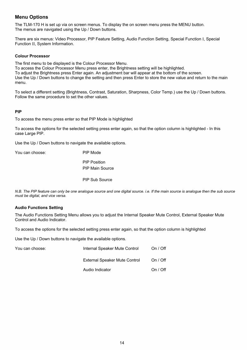
Menu Options
The TLM-170 H is set up via on screen menus. To display the on screen menu press the MENU button. The menus are navigated using the Up / Down buttons. There are six menus: Video Processor, PIP Feature Setting, Audio Function Setting, Special Function I, Special Function II, System Information.
Colour Processor
The first menu to be displayed is the Colour Processor Menu. To access the Colour Processor Menu press enter, the Brightness setting will be highlighted. To adjust the Brightness press Enter again. An adjustment bar will appear at the bottom of the screen. Use the Up / Down buttons to change the setting and then press Enter to store the new value and return to the main menu. To select a different setting (Brightness, Contrast, Saturation, Sharpness, Color Temp.) use the Up / Down buttons. Follow the same procedure to set the other values.
PIP
To access the menu press enter so that PIP Mode is highlighted
To access the options for the selected setting press enter again, so that the option column is highlighted - In this case Large PIP. Use the Up / Down buttons to navigate the available options. You can choose:
PIP Mode
PIP Position
PIP Main Source
PIP Sub Source
N.B. The PIP feature can only be one analogue source and one digital source. i.e. If the main source is analogue then the sub source must be digital, and vice versa.
Audio Functions Setting
The Audio Functions Setting Menu allows you to adjust the Internal Speaker Mute Control, External Speaker Mute Control and Audio Indicator. To access the options for the selected setting press enter again, so that the option column is highlighted Use the Up / Down buttons to navigate the available options. You can choose:
Internal Speaker Mute Control On / Off
External Speaker Mute Control On / Off
Audio Indicator On / Off
15
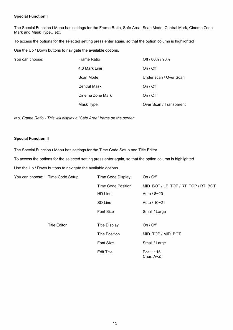
Special Function I
The Special Function I Menu has settings for the Frame Ratio, Safe Area, Scan Mode, Central Mark, Cinema Zone Mark and Mask Type…etc. To access the options for the selected setting press enter again, so that the option column is highlighted Use the Up / Down buttons to navigate the available options. You can choose:
Frame Ratio
Off / 80% / 90%
4:3 Mark Line On / Off
Scan Mode Under scan / Over Scan
Central Mask On / Off
Cinema Zone Mark
On / Off
Mask Type Over Scan / Transparent
N.B. Frame Ratio - This will display a “Safe Area” frame on the screen
Special Function II
The Special Function I Menu has settings for the Time Code Setup and Title Editor. To access the options for the selected setting press enter again, so that the option column is highlighted Use the Up / Down buttons to navigate the available options. You can choose:
Time Code Setup Time Code Display
On / Off
Time Code Position MID_BOT / LF_TOP / RT_TOP / RT_BOT
HD Line Auto / 8~20
SD Line Auto / 10~21
Font Size
Small / Large
Title Editor Title Display On / Off
Title Position MID_TOP / MID_BOT
Font Size Small / Large
Edit Title Pos: 1~15 Char: A~Z

16
System Information The System Information Menu displays the Firmware Version of the monitor, and offers a Factory Reset option, which will return all the settings of the monitor to the factory defaults.
To access the options for the selected setting press enter again, so that the option column is highlighted Use the Up / Down buttons to navigate the available options.
You can choose:
Black Light 1~16
Factory Reset Yes / No
To reset the monitor press the ENTER button, so that Factory Reset is highlighted, and then press ENTER again to highlight the options column. Use the UP / Down button to select YES from the options and then press ENTER to reset the monitor. After a few seconds the monitor will be reset.

17
Transition Effects
Right to Left / Left to Right
Top to Bottom / Bottom to UP
Middle extend L/R / Middle extend R/L
Middle extend U/D / Middle extend D/U
Inside Out / Outside In (Round)
Inside Out / Outside In (Diamond)
Inside Out / Outside In (Square)
Upper Left to Lower Right / Lower Right to Upper Left
Inverse effect move way.
Also known as a fade, is a transition wherein all the pixels of one source are replaced by all the pixels of another, at a smooth rate, and at the same time.
Controls the border softness of the effect transforming.
Press the button once and the video freezes, press it again, and it returns to the selected source in full motion.
18
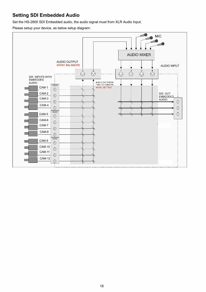
Setting SDI Embedded Audio Set the HS-2800 SDI Embedded audio, the audio signal must from XLR Audio Input.
Please setup your device, as below setup diagram:
19
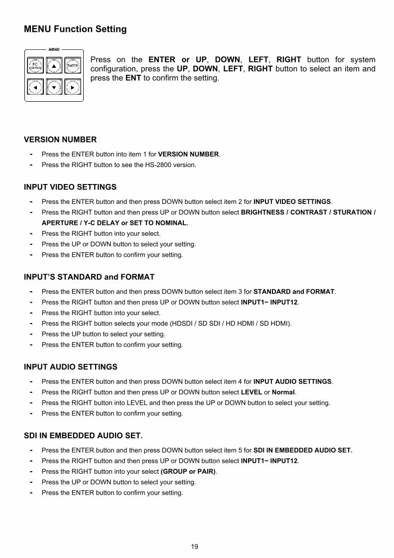
MENU Function Setting
Press on the ENTER or UP, DOWN, LEFT, RIGHT button for system configuration, press the UP, DOWN, LEFT, RIGHT button to select an item and press the ENT to confirm the setting.
VERSION NUMBER
- Press the ENTER button into item 1 for VERSION NUMBER.
- Press the RIGHT button to see the HS-2800 version.
INPUT VIDEO SETTINGS
- Press the ENTER button and then press DOWN button select item 2 for INPUT VIDEO SETTINGS.
- Press the RIGHT button and then press UP or DOWN button select BRIGHTNESS / CONTRAST / STURATION /
APERTURE / Y-C DELAY or SET TO NOMINAL.
- Press the RIGHT button into your select.
- Press the UP or DOWN button to select your setting.
- Press the ENTER button to confirm your setting.
INPUT’S STANDARD and FORMAT
- Press the ENTER button and then press DOWN button select item 3 for STANDARD and FORMAT.
- Press the RIGHT button and then press UP or DOWN button select INPUT1~ INPUT12.
- Press the RIGHT button into your select.
- Press the RIGHT button selects your mode (HDSDI / SD SDI / HD HDMI / SD HDMI).
- Press the UP button to select your setting.
- Press the ENTER button to confirm your setting.
INPUT AUDIO SETTINGS
- Press the ENTER button and then press DOWN button select item 4 for INPUT AUDIO SETTINGS.
- Press the RIGHT button and then press UP or DOWN button select LEVEL or Normal.
- Press the RIGHT button into LEVEL and then press the UP or DOWN button to select your setting.
- Press the ENTER button to confirm your setting.
SDI IN EMBEDDED AUDIO SET.
- Press the ENTER button and then press DOWN button select item 5 for SDI IN EMBEDDED AUDIO SET.
- Press the RIGHT button and then press UP or DOWN button select INPUT1~ INPUT12.
- Press the RIGHT button into your select (GROUP or PAIR).
- Press the UP or DOWN button to select your setting.
- Press the ENTER button to confirm your setting.
20
HDMI IN EMB. AUDIO PAIR
- Press the ENTER button and then press DOWN button select item 6 for HDMI IN EMB. AUDIO PAIR.
- Press the RIGHT button and then press UP or DOWN button select INPUT4 / INPUT8 / INPUT12.
- Press the RIGHT button into your select.
- Press the UP or DOWN button to select your setting.
- Press the ENTER button to confirm your setting.
OUTPUTS EMB. AUDIO PAIR
- Press the ENTER button and then press DOWN button select item 7 for OUTPUTS EMB. AUDIO PAIR.
- Press the RIGHT button and then press UP or DOWN button select OUT1 / OUT2 / OUT3.
- Press the RIGHT button into your select.
- Press the UP or DOWN button to select your setting.
- Press the ENTER button to confirm your setting.
AUTO AUDIO MIXING TYPE
- Press the ENTER button and then press DOWN button select item 8 for AUTO AUDIO MIXING TYPE.
- Press the RIGHT button and then press UP or DOWN button select X-TYPE / Y-TYPE.
- Press the RIGHT button into your select.
- Press the UP button to select your setting.
- Press the ENTER button to confirm your setting.
T-BAR AUDIO MIXING TYPE
- Press the ENTER button and then press DOWN button select item 9 for T-BAR AUDIO MIXING TYPE.
- Press the RIGHT button to select FOLLOW AUDIO MIXING TYPE / BY THE END.
- Press the UP button to select your setting.
- Press the ENTER button to confirm your setting.
PIP SETTINGS
- Press the ENTER button and then press DOWN button select item 10 for PIP SETTINGS.
- Press the RIGHT button and then press UP or DOWN button select POSITON PIP1 / SIZE PIP1 / BORDER PIP1
/ POSITON PIP2 / SIZE PIP2 / BORDER PIP2 or SET TO NOMINAL.
- Press the RIGHT button and then press UP or DOWN button into your select.
- Press the RIGHT button into your select.
- Press the UP or DOWN button to select your setting.
- Press the ENTER button to confirm your setting.
LOGO SETTINGS
- Press the ENTER button and then press DOWN button select item 11 for LOGO SETTINGS.
- Press the RIGHT button to select LOGO1 / LOGO2.
- Press the RIGHT button and select X-POSITON / Y-POSITON.
- Press the UP or DOWN button to select your setting.
- Press the ENTER button to confirm your setting.
21
SPEED BUTTONS SETTING
- Press the ENTER button and then press DOWN button select item 12 for SPEED BUTTONS SETTING.
- Press the RIGHT button to select SPEED 1 / SPEED 2 / SPEED3.
- Press the RIGHT button into your select.
- Press the UP or DOWN button to select your setting.
- Press the ENTER button to confirm your setting.
WIPE BUTTONS SETTING
- Press the ENTER button and then press DOWN button select item 13 for WIPE BUTTONS SETTING.
- Press the RIGHT button and then press UP or DOWN button select BUTTON 1~ BUTTON 6.
- Press the RIGHT button into your select (WIPE, SOFT EDGE or COLOR).
- Press the RIGHT button into your select.
- Press the UP or DOWN button to select your setting.
- Press the ENTER button to confirm your setting.
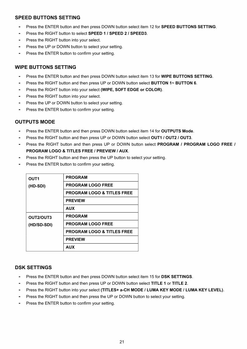
OUTPUTS MODE
- Press the ENTER button and then press DOWN button select item 14 for OUTPUTS Mode.
- Press the RIGHT button and then press UP or DOWN button select OUT1 / OUT2 / OUT3.
- Press the RIGHT button and then press UP or DOWN button select PROGRAM / PROGRAM LOGO FREE /
PROGRAM LOGO & TITLES FREE / PREVIEW / AUX.
- Press the RIGHT button and then press the UP button to select your setting.
- Press the ENTER button to confirm your setting.
OUT1
(HD-SDI)
PROGRAM
PROGRAM LOGO FREE
PROGRAM LOGO & TITLES FREE
PREVIEW
AUX
OUT2/OUT3
(HD/SD-SDI)
PROGRAM
PROGRAM LOGO FREE
PROGRAM LOGO & TITLES FREE
PREVIEW
AUX
DSK SETTINGS
- Press the ENTER button and then press DOWN button select item 15 for DSK SETTINGS.
- Press the RIGHT button and then press UP or DOWN button select TITLE 1 or TITLE 2.
- Press the RIGHT button into your select (TITLES+ a-CH MODE / LUMA KEY MODE / LUMA KEY LEVEL).
- Press the RIGHT button and then press the UP or DOWN button to select your setting.
- Press the ENTER button to confirm your setting.

22
BG COLOR SETTING
- Press the ENTER button and then press DOWN button select item 16 for BG COLOR SETTING.
- Press the RIGHT and then press UP or DOWN button select your setting.
- Press the ENTER button to confirm your setting.
T-BAR MODE
- Press the ENTER button and then press DOWN button select item 17 for T-BAR MODE.
- Press the RIGHT button and then press UP or DOWN button select ONE WAY MODE or TWO WAY MODE.
- Press the RIGHT button and then press the UP button to select your setting.
- Press the ENTER button to confirm your setting.
1KHz to BARS
- Press the ENTER button and then press DOWN button select item 18 for 1KHz to BARS.
- Press the RIGHT and then press UP button select your setting.
- Press the ENTER button to confirm your setting.
KEYS BRIGHTNESS
- Press the ENTER button and then press DOWN button select item 19 for KEYS BRIGHTNESS.
- Press the RIGHT and then press UP or DOWN button select your setting.
- Press the ENTER button to confirm your setting.
KEYS MODE
- Press the ENTER button and then press DOWN button select item 20 for KEYS MODE.
- Press the RIGHT and then press UP button select your setting.
- Press the ENTER button to confirm your setting.
AUDIO LEVEL IS SHOWN
- Press the ENTER button and then press DOWN button select item 21 for AUDIO LEVEL IS SHOWN.
- Press the RIGHT and then press UP or DOWN button select your setting.
- Press the ENTER button to confirm your setting.
REFERENCE
- Press the ENTER button and then press DOWN button select item 22 for REFERENCE.
- Press the RIGHT button and then press UP or DOWN button select EXTERNAL / MODE / H-TIMNG.
- Press the RIGHT button and then press the UP button to select your setting.
- Press the ENTER button to confirm your setting.
AUX
- Press the ENTER button and then press DOWN button select item 23 for AUX.
- Press the RIGHT and then press UP or DOWN button select your setting.
- Press the ENTER button to confirm your setting.
23
FACTORY SETTINGS
- Press the ENTER button and then press DOWN button select item 24 for FACTORY SETTINGS.
- Press the RIGHT and then press UP button select your setting.
- Press the ENTER button to confirm your setting.
CLOCK SETTINGS
- Press the ENTER button and then press DOWN button select item 25 for CLOCK SETTINGS.
- Press the RIGHT button to select X-POSITON / Y-POSITON / SET HOURS / SET MINUTES / CLEAR
SECONDS.
- Press the RIGHT and then press UP or DOWN button select your setting.
- Press the ENTER button to confirm your setting.
MULTISCREEN MODE
- Press the ENTER button and then press DOWN button select item 26 for MULTISCREEN MODE.
- Press the RIGHT button to select
- A: W1=9 IN; W2=3 IN+PVW+PGM / B: W1=12 IN+PGM+PVW; W2=PGM /
- C: W1=8 IN+PGM+PVW; W2=PGM / D: W1=12 IN+PGM+PVW;W2=W1 /
- E: W1=8 IN+PGM+PVW; W2=W1.
- Press the RIGHT and then press UP button select your setting.
- Press the ENTER button to confirm your setting.
GPI SETTINGS
- Press the ENTER button and then press DOWN button select item 27 for GPI SETTINGS.
- Press the RIGHT button and then press UP or DOWN button to select INPUT SELECT / TIME DELAY.
- Press the RIGHT and then press UP or DOWN button select your setting.
- Press the ENTER button to confirm your setting.
COUNT DOWN TIMER SETTINGS
- Press the ENTER button and then press DOWN button select item 28 for COUNT DOWN TIMER SETTINGS.
- Press the RIGHT button and then press UP or DOWN button to select INPUT1~ INPUT12.
- Press the RIGHT and then press UP or DOWN button select COUNT DOWN ON / DOWN COUNTER VALUE.
- Press the RIGHT button and then press UP or DOWN button to select your setting.
- Press the ENTER button to confirm your setting.
24
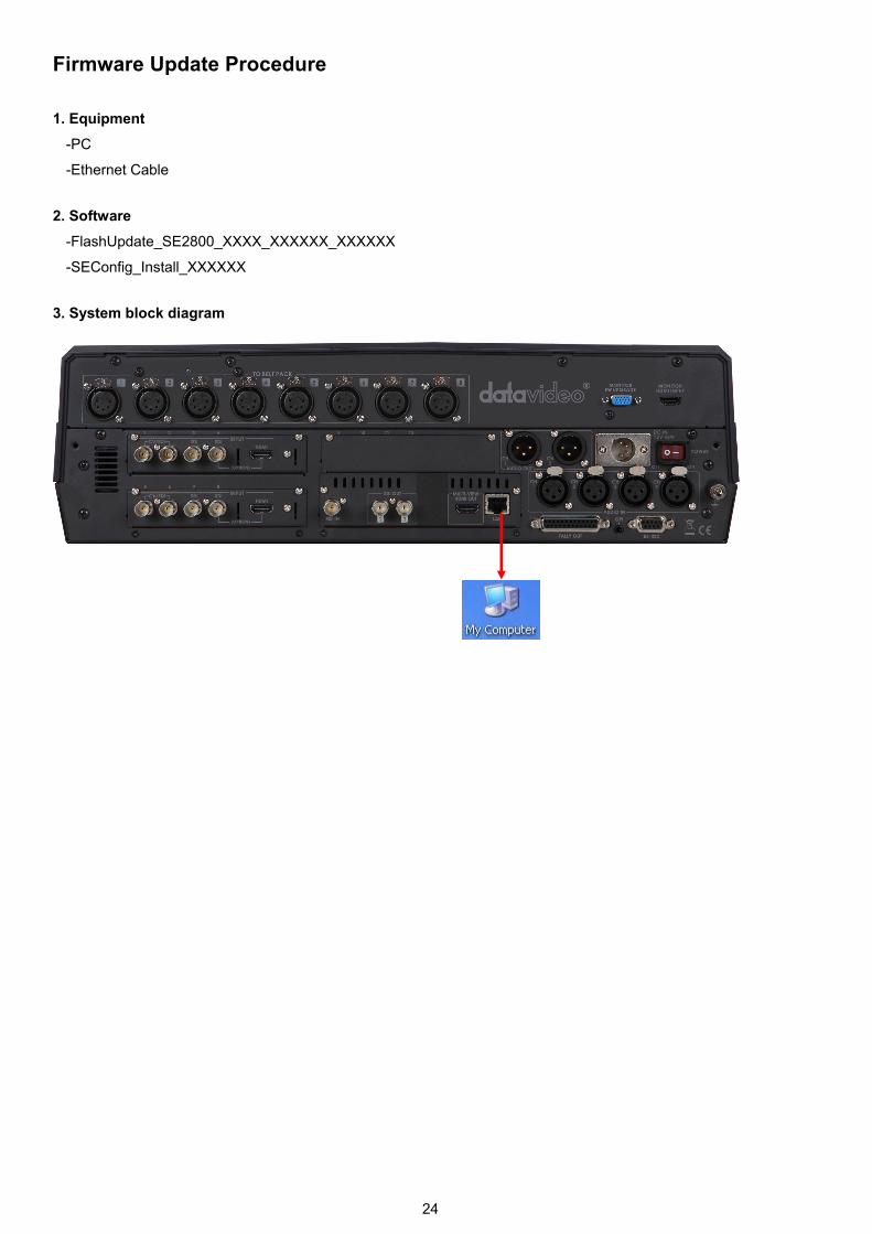
Firmware Update Procedure
1. Equipment
-PC
-Ethernet Cable
2. Software
-FlashUpdate_SE2800_XXXX_XXXXXX_XXXXXX
-SEConfig_Install_XXXXXX
3. System block diagram

25
4. Software update step
- Firmware download can be performed when all the initialized modules have been mounted into the main unit. The initialized keyboard must be connected. Connect the device to PC via LAN and launch LASHUPDATE.exe in the PC. The update utility must establish connection with the device. Follow onscreen notes to download application firmware in automatic mode.
- Set PC LAN
- IP Address:192.168.0.11
- Subnet Mask :255.255.255.0
- Default Gateway:192.168.0.1
26
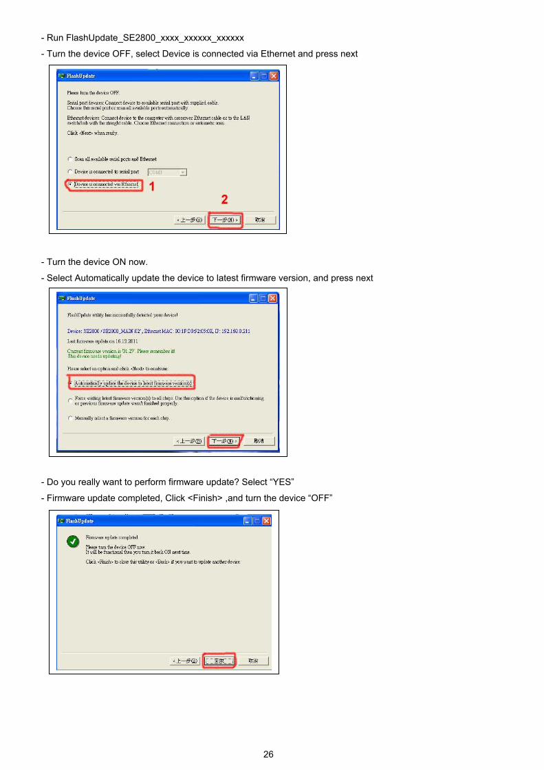
- Run FlashUpdate_SE2800_xxxx_xxxxxx_xxxxxx
- Turn the device OFF, select Device is connected via Ethernet and press next
- Turn the device ON now.
- Select Automatically update the device to latest firmware version, and press next
- Do you really want to perform firmware update? Select “YES”
- Firmware update completed, Click <Finish> ,and turn the device “OFF”
27
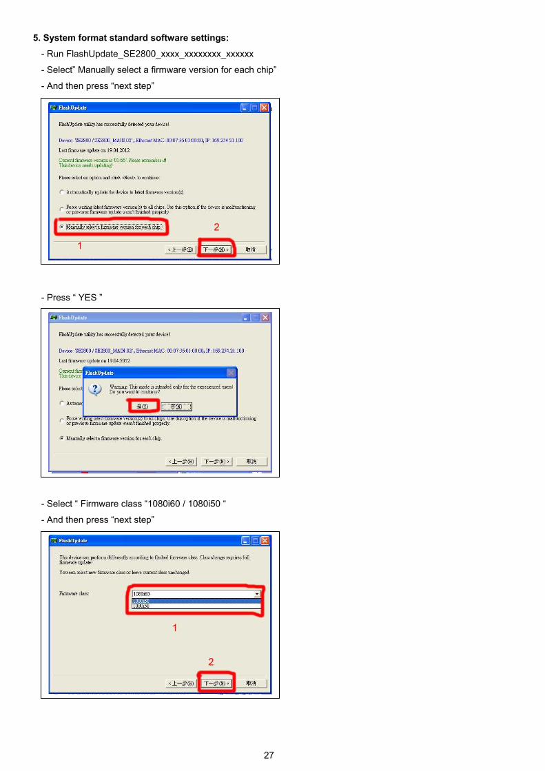
5. System format standard software settings:
- Run FlashUpdate_SE2800_xxxx_xxxxxxxx_xxxxxx
- Select” Manually select a firmware version for each chip”
- And then press “next step”
- Press “ YES ”
- Select “ Firmware class “1080i60 / 1080i50 “
- And then press “next step”

28
- And then press “next step”
‧
- And then press “next step”
- Select “YES“
29
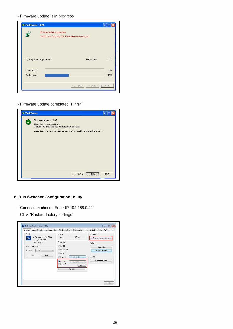
- Firmware update is in progress
- Firmware update completed “Finish”
6. Run Switcher Configuration Utility
- Connection choose Enter IP 192.168.0.211
- Click “Restore factory settings”

30
7. Calibrating the T-bar
After a firmware update of the switcher it will be necessary to re-calibrate the T-Bar to get it working correctly.
1. Move the T-Bar to its lowest position.
2. Power OFF the SE-2800 switcher.
3. Press and hold down button 1 on both the Program and
Preset rows of the switcher’s keyboard.
4. Power ON the SE-2800 switcher while still holding down
the buttons in step 3.
5. The switcher will start but the keyboard lights will remain dead except for the T-Bar progress LEDs. When these LEDs flash ON and OFF release the buttons from step 3.
6. Move the T-Bar to almost its top position (2-3mm away) and then press the CUT button.
7. Move the T-Bar back to almost its lowest position (2-3mm away) and then press the AUTO TAKE button.
8. To exit the calibration procedure press the CLOCK button.
9. Ensure the TIMER button is OFF.
10. Test the T-Bar. If necessary change the T-Bar Mode in the OSD MENU options.

31
LOGOS Setup Static Logos
HS-2800 can store 7 static logos. SEConfig bookmark "Logos".
The static Logos to be loaded and written into 1 to 7 memory slots must be 256x128 pixels. This Logos must be created
in a graphics software package first as:
• TGA 32bit with a clear Alpha Channel background.
• PNG 32bit with a clear Alpha Channel background.
• GIF.Indexed color 8 bit with a transparent background but without translucent shadow.
• BMP 24bit file - without a transparent background. It is possible to use the pair of BMP files for clear Alpha
Channel BG added by SEConfig: The first file - Logo with Black background named as xxx.bmp , the second -
Logo with white background named as xxx_w.bmp. The SEConfig accept this pair as one picture.
• JPG 24bit file - without a transparent background.
It can be possible to save logos in the own SEConfig format lbl or bin and Load it by SEConfig

32
Dynamic Logo
SE -2800 can store 1 dynamic logo. SEConfig bookmark "Dynamic Logo".
This Logo needs to be created in a graphics software package first as a sequence of up to 75 image. Image size must
be 256 x 128 pix, 8 bits/channel
Format is the same as for Static Logos:
• TGA 8 bit/channel - with a clear Alpha Channel background.
• PNG 8 bit/channel - with a clear Alpha Channel background.
• GIF Indexed color 8 bit with a transparent background but without translucent shadow.
• BMP 8 bit/channel file - without a transparent background. It is possible to use the pair of BMP files for clear
Alpha Channel BG added by SEConfig: The first file - Logo with Black background named as xxx.bmp, the
second - Logo with white t background named as xxx_w.bmp. The SEConfig accept this pair as one picture.
• JPG 24bit file - without a transparent background. And supplementary:
• AVI
• Animated GIF
Dynamic Logos' picture display sequence is determined by the number in the name (Note: for the correct sorting, the
number in the name must have 2 digits: 01. 02 ... 09, 10...)
The source files must be imported into the included editor: Button Edit", then button "Import" Each frame can have its
own "Show time" (40ms step).
The button "Play" can show preview - if everything is fine; the new Dynamic Logo must be saved as xxx.dlb file which
can stored in the device : button "Load" ( select xxx.dlb) and then button "Write" - write to Slot1 .

33
Tally Connector Pin Assignment The output signals from the tally output pins are for lighting the tally lamps, and these outputs are open collector outputs. Pin assignment
Pin No. Signal name Input/Output Description of signal
1 Program 1 Open collector output Tally output of input video Program 1
2 Program 2 Open collector output Tally output of input video Program 2
3 Program 3 Open collector output Tally output of input video Program 3
4 Program 4 Open collector output Tally output of input video Program 4
5 Program 5 Open collector output Tally output of input video Program 5
6 Program 6 Open collector output Tally output of input video Program 6
7 Program 7 Open collector output Tally output of input video Program 7
8 Program 8 Open collector output Tally output of input video Program 8
9 Program 9 Open collector output Tally output of input video Program 9
10 Program 10 Open collector output Tally output of input video Program 10
11 Program 11 Open collector output Tally output of input video Program 11
12 Program 12 Open collector output Tally output of input video Program 12
13 GND Ground Ground
14 Preset 1 Open collector output Tally output of input video Preset 1
15 Preset 2 Open collector output Tally output of input video Preset 2
16 Preset 3 Open collector output Tally output of input video Preset 3
17 Preset 4 Open collector output Tally output of input video Preset 4
18 Preset 5 Open collector output Tally output of input video Preset 5
19 Preset 6 Open collector output Tally output of input video Preset 6
20 Preset 7 Open collector output Tally output of input video Preset 7
21 Preset 8 Open collector output Tally output of input video Preset 8
22 Preset 9 Open collector output Tally output of input video Preset 9
23 Preset 10 Open collector output Tally output of input video Preset 10
24 Preset 11 Open collector output Tally output of input video Preset 11
25 Preset 12 Open collector output Tally output of input video Preset 12
(D-sub 25-Pin Female)

34
Pin 1 to25 must satisfy the following conditions: Dielectric strength: Max. DC 24V
Current: Max. 50mA
(Max. current: 50mA)
12
SE-3000TALLY OUTPUT
(Max. voltage:24V)VCC
Ground
Tally LED
R
12
Example of tally connections
HS-2800
35
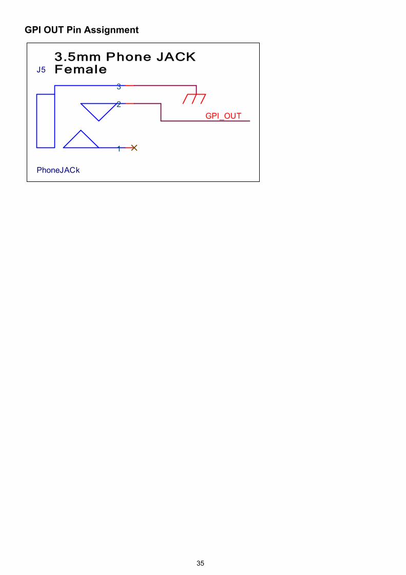
GPI OUT Pin Assignment
J5
PhoneJACk
1
2
3
3.5mm Phone JACKFemale
GPI_OUT
36
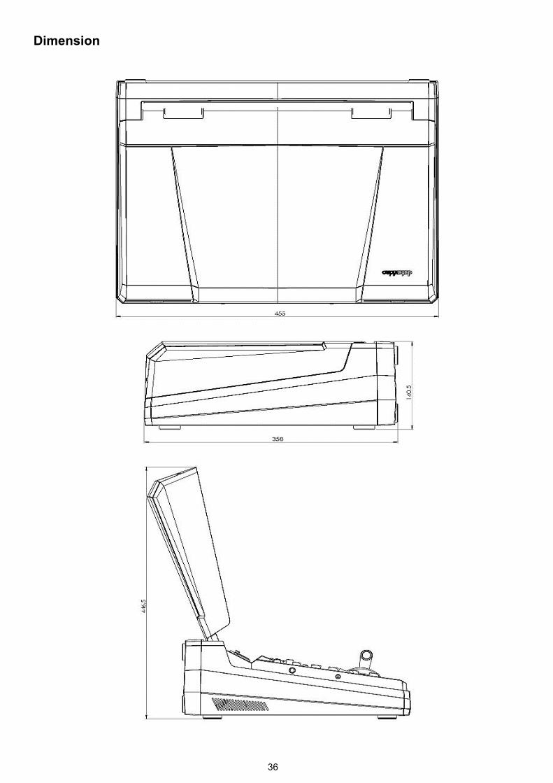
Dimension
37
Specification
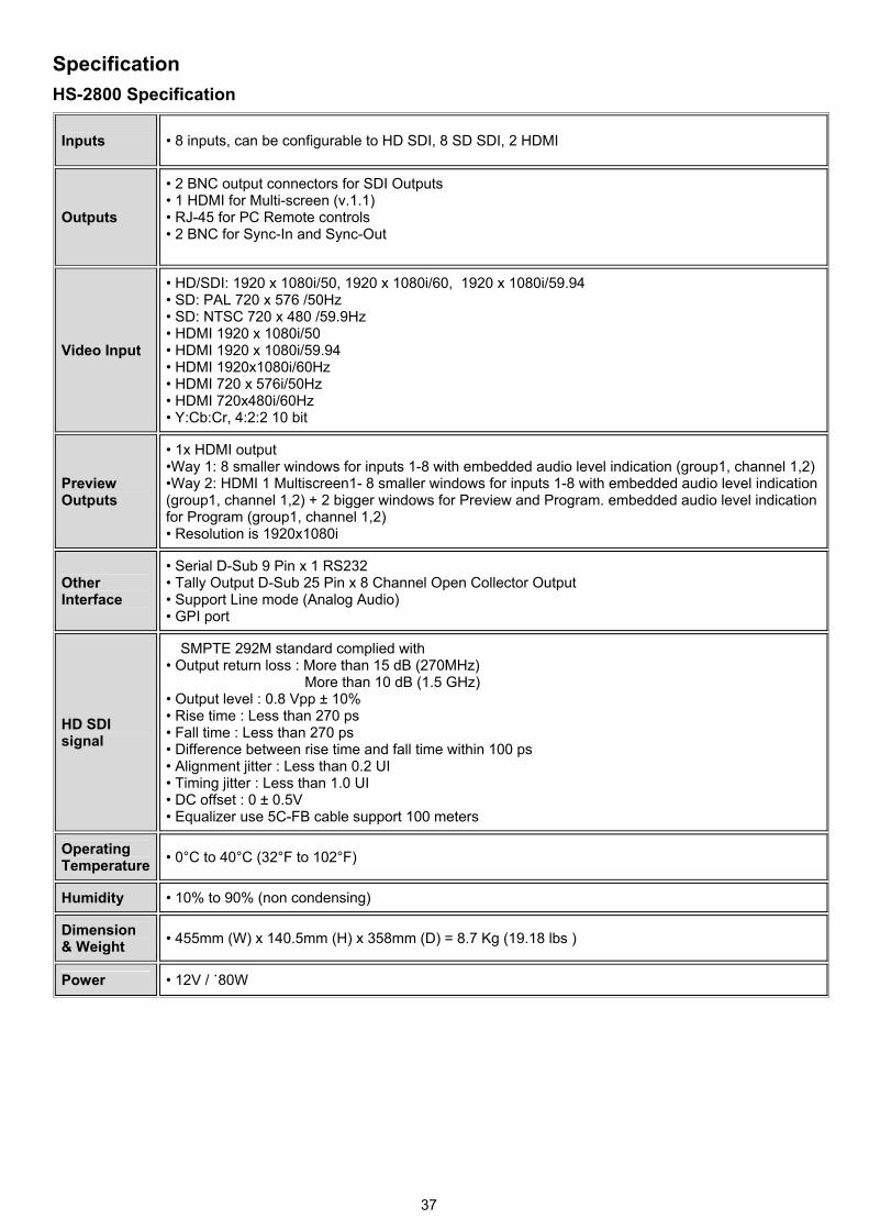
HS-2800 Specification
Inputs • 8 inputs, can be configurable to HD SDI, 8 SD SDI, 2 HDMI
Outputs
• 2 BNC output connectors for SDI Outputs • 1 HDMI for Multi-screen (v.1.1) • RJ-45 for PC Remote controls • 2 BNC for Sync-In and Sync-Out
Video Input
• HD/SDI: 1920 x 1080i/50, 1920 x 1080i/60, 1920 x 1080i/59.94 • SD: PAL 720 x 576 /50Hz • SD: NTSC 720 x 480 /59.9Hz • HDMI 1920 x 1080i/50 • HDMI 1920 x 1080i/59.94 • HDMI 1920x1080i/60Hz • HDMI 720 x 576i/50Hz • HDMI 720x480i/60Hz • Y:Cb:Cr, 4:2:2 10 bit
Preview Outputs
• 1x HDMI output •Way 1: 8 smaller windows for inputs 1-8 with embedded audio level indication (group1, channel 1,2)•Way 2: HDMI 1 Multiscreen1- 8 smaller windows for inputs 1-8 with embedded audio level indication (group1, channel 1,2) + 2 bigger windows for Preview and Program. embedded audio level indication for Program (group1, channel 1,2) • Resolution is 1920x1080i
Other Interface
• Serial D-Sub 9 Pin x 1 RS232 • Tally Output D-Sub 25 Pin x 8 Channel Open Collector Output • Support Line mode (Analog Audio) • GPI port
HD SDI signal
SMPTE 292M standard complied with • Output return loss : More than 15 dB (270MHz)
More than 10 dB (1.5 GHz) • Output level : 0.8 Vpp ± 10% • Rise time : Less than 270 ps • Fall time : Less than 270 ps • Difference between rise time and fall time within 100 ps • Alignment jitter : Less than 0.2 UI • Timing jitter : Less than 1.0 UI • DC offset : 0 ± 0.5V • Equalizer use 5C-FB cable support 100 meters
Operating Temperature
• 0°C to 40°C (32°F to 102°F)
Humidity • 10% to 90% (non condensing)
Dimension & Weight
• 455mm (W) x 140.5mm (H) x 358mm (D) = 8.7 Kg (19.18 lbs )
Power • 12V / ˙80W
38
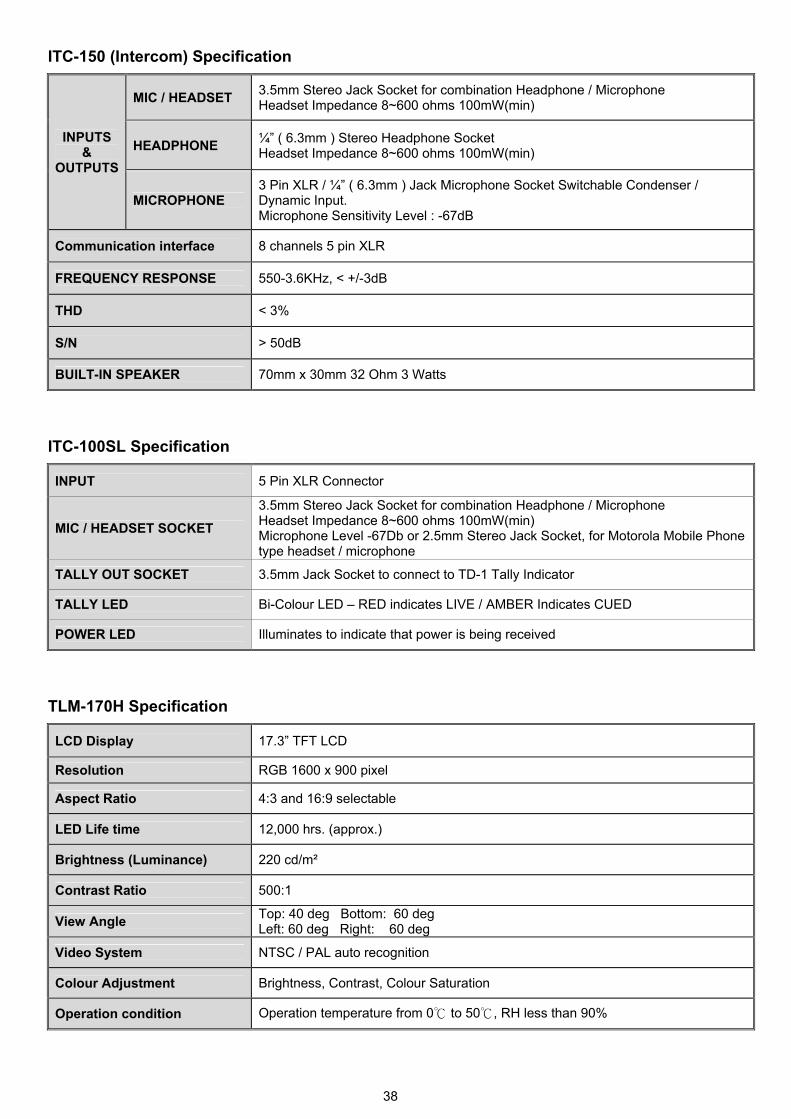
ITC-150 (Intercom) Specification
INPUTS &
OUTPUTS
MIC / HEADSET 3.5mm Stereo Jack Socket for combination Headphone / Microphone Headset Impedance 8~600 ohms 100mW(min)
HEADPHONE ¼” ( 6.3mm ) Stereo Headphone Socket Headset Impedance 8~600 ohms 100mW(min)
MICROPHONE 3 Pin XLR / ¼” ( 6.3mm ) Jack Microphone Socket Switchable Condenser / Dynamic Input. Microphone Sensitivity Level : -67dB
Communication interface 8 channels 5 pin XLR
FREQUENCY RESPONSE 550-3.6KHz, < +/-3dB
THD < 3%
S/N > 50dB
BUILT-IN SPEAKER 70mm x 30mm 32 Ohm 3 Watts
ITC-100SL Specification
INPUT 5 Pin XLR Connector
MIC / HEADSET SOCKET
3.5mm Stereo Jack Socket for combination Headphone / Microphone Headset Impedance 8~600 ohms 100mW(min) Microphone Level -67Db or 2.5mm Stereo Jack Socket, for Motorola Mobile Phone type headset / microphone
TALLY OUT SOCKET 3.5mm Jack Socket to connect to TD-1 Tally Indicator
TALLY LED Bi-Colour LED – RED indicates LIVE / AMBER Indicates CUED
POWER LED Illuminates to indicate that power is being received
TLM-170H Specification
LCD Display 17.3” TFT LCD
Resolution RGB 1600 x 900 pixel
Aspect Ratio 4:3 and 16:9 selectable
LED Life time 12,000 hrs. (approx.)
Brightness (Luminance) 220 cd/m²
Contrast Ratio 500:1
View Angle Top: 40 deg Bottom: 60 deg Left: 60 deg Right: 60 deg
Video System NTSC / PAL auto recognition
Colour Adjustment Brightness, Contrast, Colour Saturation
Operation condition Operation temperature from 0℃ to 50℃, RH less than 90%
39
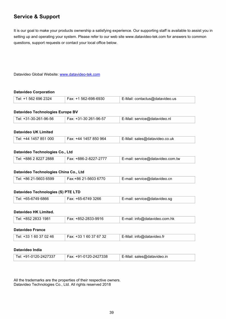
Service & Support
It is our goal to make your products ownership a satisfying experience. Our supporting staff is available to assist you in
setting up and operating your system. Please refer to our web site www.datavideo-tek.com for answers to common
questions, support requests or contact your local office below.
Datavideo Global Website: www.datavideo-tek.com Datavideo Corporation
Tel: +1 562 696 2324 Fax: +1 562-698-6930 E-Mail: [email protected]
Datavideo Technologies Europe BV
Tel: +31-30-261-96-56 Fax: +31-30 261-96-57 E-Mail: [email protected]
Datavideo UK Limited
Tel: +44 1457 851 000 Fax: +44 1457 850 964 E-Mail: [email protected]
Datavideo Technologies Co., Ltd
Tel: +886 2 8227 2888 Fax: +886-2-8227-2777 E-mail: [email protected]
Datavideo Technologies China Co., Ltd
Tel: +86 21-5603 6599 Fax:+86 21-5603 6770 E-mail: [email protected]
Datavideo Technologies (S) PTE LTD
Tel: +65-6749 6866 Fax: +65-6749 3266 E-mail: [email protected]
Datavideo HK Limited.
Tel: +852 2833 1981 Fax: +852-2833-9916 E-mail: [email protected]
Datavideo France
Tel: +33 1 60 37 02 46 Fax: +33 1 60 37 67 32 E-Mail: [email protected]
Datavideo India
Tel: +91-0120-2427337 Fax: +91-0120-2427338 E-Mail: [email protected]
All the trademarks are the properties of their respective owners. Datavideo Technologies Co., Ltd. All rights reserved 2018