hrm-0800 instruction manual · hrm-0800 instruction manual. ... (green ) 5. ch1-8 over current...
TRANSCRIPT
HRM-0800Instruction
Manual
Table of Contents1 Highway Addressable Remote Transducer (HART™) 42 General Specifications 53 Dimensions: 64 General Description 74.1 Introduction 74.2 Purpose 84.3 Functions 85 HRM0800 Presentation 96 Features 106.1 Two Ethernet-Switch Ports 106.2 4-20mA Pass-Through 106.3 Built-in Filters and Resistor Terminations 106.4 DC to DC Converter 107 RS-485 Pass Through Operation 117.1 Connections Details 118 Hardware 128.1 DIP-switches S1, S2 and S3 128.2 HE10 Connection 128.2.1 HE10 Pin-Out 138.3 Connections for Field Devices 148.3.1 Passive Transmitter with Analog Input Module Connections 148.3.2 Active Transmitter (example for a 24VDC supply Transmitter) 148.3.3 Smart valve 148.3.4 Without Analog I/O card 159 Operation 169.1 Power ON Behavior 169.2 LED Indications 1610 Holding registers (% MW) Memory map 1710.1 MODBUS Holding Registers (460000 to 460007) 1910.2 MODBUS Holding Registers (460011) 1911 Web Server 2011.1 Ethernet Setup 2011.1.1 Static IP Address 2011.2 Embedded Web Pages 2411.2.1 Home Page 2411.2.2 Monitoring 2411.2.2.1 Device Information 2511.2.2.2 Run Time Parameters 2611.2.3 Diagnostic Page 2711.2.3.1 Ethernet Statistics 2711.2.3.2 HRM0800 Statistics 2811.2.4 HRM0800 Setup 2811.2.4.1 Configure IP 2911.2.4.2 Comm. Settings 3011.2.4.3 HRM0800 Configuration 31Appendix A: Installation recommendations 3412.1 Ethernet architecture 3412.2 Grounding topology according to north America principles 35
REVISION HISTORY 36

Instruction Manual: HRM0800 Pub.: 01/2013 Rev. 1.00
4
1 Highway Addressable Remote Transducer (HART™)
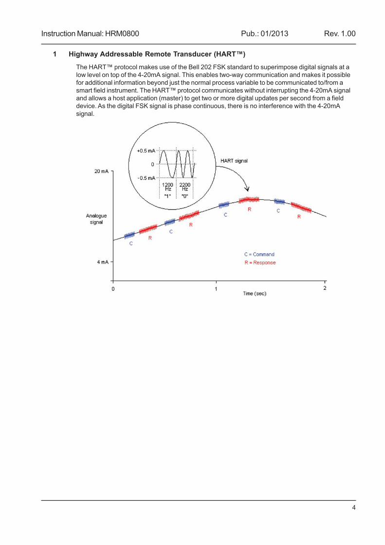
The HART™ protocol makes use of the Bell 202 FSK standard to superimpose digital signals at alow level on top of the 4-20mA signal. This enables two-way communication and makes it possiblefor additional information beyond just the normal process variable to be communicated to/from asmart field instrument. The HART™ protocol communicates without interrupting the 4-20mA signaland allows a host application (master) to get two or more digital updates per second from a fielddevice. As the digital FSK signal is phase continuous, there is no interference with the 4-20mAsignal.
Instruction Manual: HRM0800 Pub.: 01/2013 Rev. 1.00
5
2 General Specifications
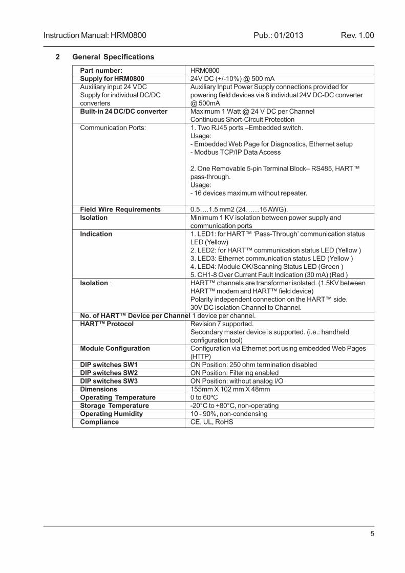
Part number: HRM0800Supply for HRM0800 24V DC (+/-10%) @ 500 mAAuxiliary input 24 VDC Auxiliary Input Power Supply connections provided forSupply for individual DC/DC powering field devices via 8 individual 24V DC-DC converterconverters @ 500mABuilt-in 24 DC/DC converter Maximum 1 Watt @ 24 V DC per Channel
Continuous Short-Circuit ProtectionCommunication Ports: 1. Two RJ45 ports –Embedded switch.
Usage:- Embedded Web Page for Diagnostics, Ethernet setup- Modbus TCP/IP Data Access
2. One Removable 5-pin Terminal Block– RS485, HART™pass-through.Usage:- 16 devices maximum without repeater.
Field Wire Requirements 0.5….1.5 mm2 (24……16 AWG).Isolation Minimum 1 KV isolation between power supply and
communication portsIndication 1. LED1: for HART™ ‘Pass-Through’ communication status
LED (Yellow)2. LED2: for HART™ communication status LED (Yellow )3. LED3: Ethernet communication status LED (Yellow )4. LED4: Module OK/Scanning Status LED (Green )5. CH1-8 Over Current Fault Indication (30 mA) (Red )
Isolation · HART™ channels are transformer isolated. (1.5KV betweenHART™ modem and HART™ field device)Polarity independent connection on the HART™ side.30V DC isolation Channel to Channel.
No. of HART™ Device per Channel 1 device per channel.HART™ Protocol Revision 7 supported.
Secondary master device is supported. (i.e.: handheldconfiguration tool)
Module Configuration Configuration via Ethernet port using embedded Web Pages(HTTP)
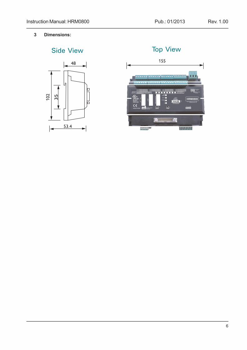
DIP switches SW1 ON Position: 250 ohm termination disabledDIP switches SW2 ON Position: Filtering enabledDIP switches SW3 ON Position: without analog I/ODimensions 155mm X 102 mm X 48mmOperating Temperature 0 to 60ºCStorage Temperature -20°C to +80°C, non-operatingOperating Humidity 10 - 90%, non-condensingCompliance CE, UL, RoHS
Instruction Manual: HRM0800 Pub.: 01/2013 Rev. 1.00
6
3 Dimensions:
Side View Top View
Instruction Manual: HRM0800 Pub.: 01/2013 Rev. 1.00
7
4 General Description
4.1 Introduction
This manual provides guidance for the installation, operation and maintenance of the productHRM0800 (8 channels HART™ Interface Multiplexer).
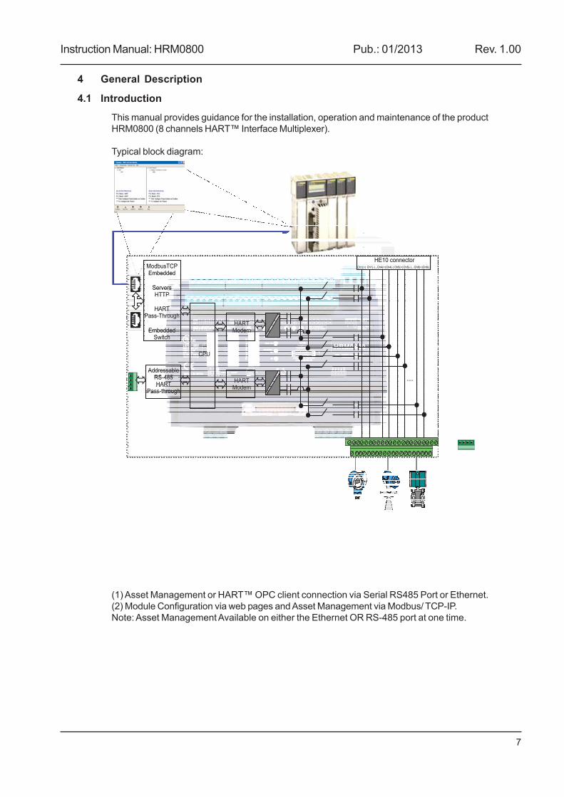
Typical block diagram:
(1) Asset Management or HART™ OPC client connection via Serial RS485 Port or Ethernet.(2) Module Configuration via web pages and Asset Management via Modbus/ TCP-IP.Note: Asset Management Available on either the Ethernet OR RS-485 port at one time.
ModbusTCPEmbedded
ServersHTTP
HARTPass-Through
EmbeddedSwitch
AddressableRS-485HART
Pass-through
CPU
HARTModem
HARTModem
HE10 connectorCh1(+) Ch1(-)...Ch4(+)Ch4(-) Ch5(+)Ch5(-)...Ch8(+)Ch8(-)
...
Instruction Manual: HRM0800 Pub.: 01/2013 Rev. 1.00
8
4.2 Purpose
The HRM0800 is a HART™ Interface Multiplexer unit, which allows access to 8 Channels HART™communications on existing 4-20mA loop.
4.3 Functions
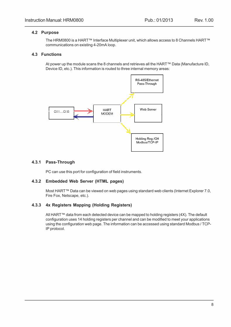
At power up the module scans the 8 channels and retrieves all the HART™ Data (Manufacture ID,Device ID, etc.). This information is routed to three internal memory areas:
4.3.1 Pass-Through
PC can use this port for configuration of field instruments.
4.3.2 Embedded Web Server (HTML pages)
Most HART™ Data can be viewed on web pages using standard web clients (Internet Explorer 7.0,Fire Fox, Netscape, etc.).
4.3.3 4x Registers Mapping (Holding Registers)
All HART™ data from each detected device can be mapped to holding registers (4X). The defaultconfiguration uses 14 holding registers per channel and can be modified to meet your applicationsusing the configuration web page. The information can be accessed using standard Modbus / TCP-IP protocol.
Instruction Manual: HRM0800 Pub.: 01/2013 Rev. 1.00
9
5 HRM0800 Presentation
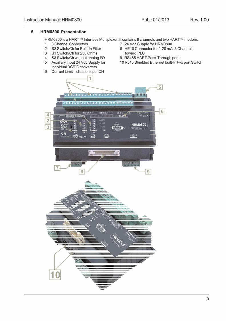
HRM0800 is a HART™ Interface Multiplexer. It contains 8 channels and two HART™ modem.1 8 Channel Connectors 7 24 Vdc Supply for HRM08002 S2 Switch/Ch for Built-In Filter 8 HE10 Connector for 4-20 mA, 8 Channels3 S1 Switch/Ch for 250 Ohms toward PLC4 S3 Switch/Ch without analog I/O 9 RS485 HART Pass-Through port5 Auxiliary input 24 Vdc Supply for 10 RJ45 Shielded Ethernet built-In two port Switch
individual DC/DC converters6 Current Limit Indications per CH
1
2
3
4
5
6
78 9
10
Instruction Manual: HRM0800 Pub.: 01/2013 Rev. 1.00
10
6 Features
6.1 Two Ethernet-Switch Ports
The HRM0800 is equipped with two Shielded Ethernet Switch ports, used to daisy chain multiplemodules.
6.2 4-20mA Pass-Through
The 4-20mA signals for each channel are accessible via the HE10 connector. Various ‘quick con-nect’ cables are available for easy connection to PLC analog input/output modules.
6.3 Built-in Filters and Resistor Terminations
The HRM0800 has three sets of 8 ‘dip switches’. Each channel has one ‘dip switch’ assigned fromeach of the sets. The first switch is used to provide internal 250 Ohms resistor loop impedancewhen the PLC analog input does not provide it. The second switch is used to enable the filtering ofthe HART information when a “smart” valve is used. The third switch is to close the current loopwhen the module is used without an analog I/O card.
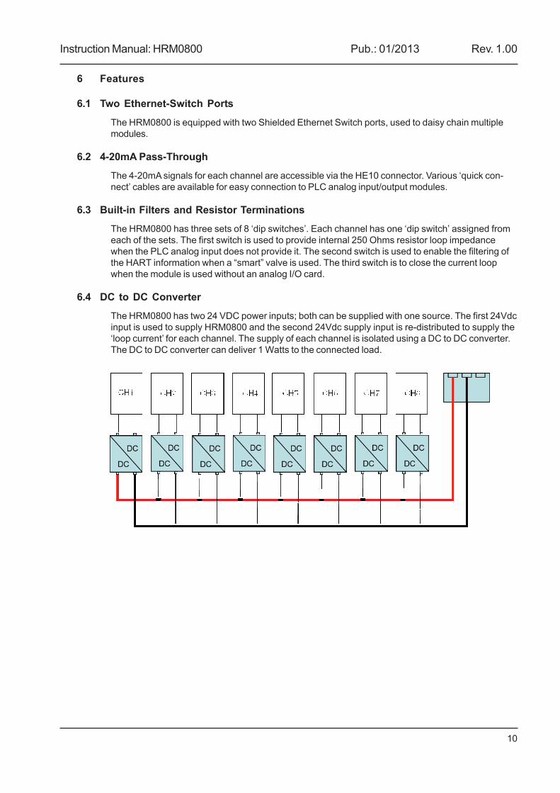
6.4 DC to DC Converter
The HRM0800 has two 24 VDC power inputs; both can be supplied with one source. The first 24Vdcinput is used to supply HRM0800 and the second 24Vdc supply input is re-distributed to supply the‘loop current’ for each channel. The supply of each channel is isolated using a DC to DC converter.The DC to DC converter can deliver 1 Watts to the connected load.
Instruction Manual: HRM0800 Pub.: 01/2013 Rev. 1.00
11
7 RS-485 Pass Through Operation
7.1 Connections Details
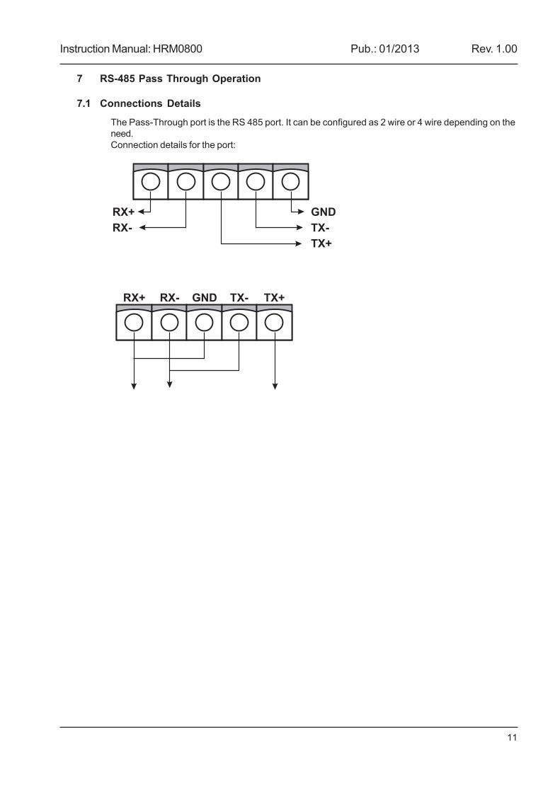
The Pass-Through port is the RS 485 port. It can be configured as 2 wire or 4 wire depending on theneed.Connection details for the port:
RX+
RX-
GND
TX-
TX+
RX+ RX- GND TX- TX+
Instruction Manual: HRM0800 Pub.: 01/2013 Rev. 1.00
12
8 HardwareTo connect field devices, 3.81mm pitch 8X6 pole double deck connector is used; six poles perchannel are needed. For the control system analog input or output module, the Quick ConnectHE10 connectors are used (please refer to Appendix A for a list of available cables and pin-outdiagrams).
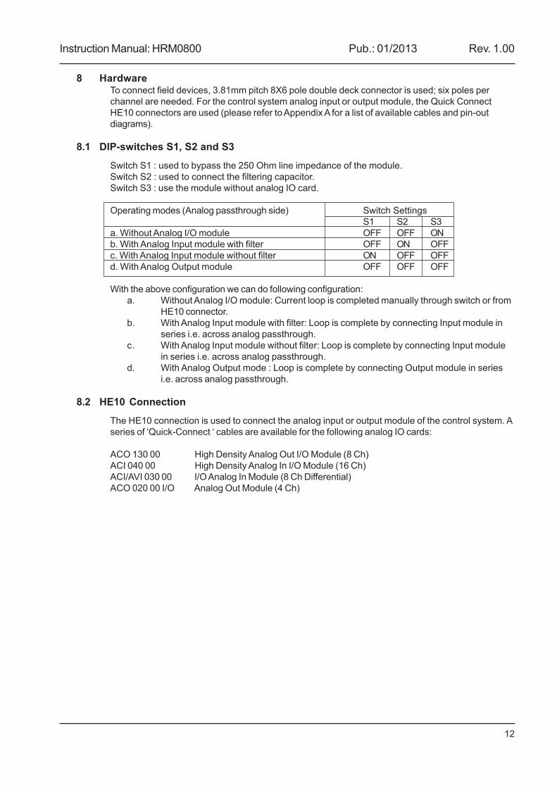
8.1 DIP-switches S1, S2 and S3
Switch S1 : used to bypass the 250 Ohm line impedance of the module.Switch S2 : used to connect the filtering capacitor.Switch S3 : use the module without analog IO card.
Operating modes (Analog passthrough side) Switch SettingsS1 S2 S3
a. Without Analog I/O module OFF OFF ONb. With Analog Input module with filter OFF ON OFFc. With Analog Input module without filter ON OFF OFFd. With Analog Output module OFF OFF OFF
With the above configuration we can do following configuration:a. Without Analog I/O module: Current loop is completed manually through switch or from
HE10 connector.b. With Analog Input module with filter: Loop is complete by connecting Input module in
series i.e. across analog passthrough.c. With Analog Input module without filter: Loop is complete by connecting Input module
in series i.e. across analog passthrough.d. With Analog Output mode : Loop is complete by connecting Output module in series
i.e. across analog passthrough.
8.2 HE10 Connection
The HE10 connection is used to connect the analog input or output module of the control system. Aseries of ‘Quick-Connect ‘ cables are available for the following analog IO cards:
ACO 130 00 High Density Analog Out I/O Module (8 Ch)ACI 040 00 High Density Analog In I/O Module (16 Ch)ACI/AVI 030 00 I/O Analog In Module (8 Ch Differential)ACO 020 00 I/O Analog Out Module (4 Ch)
Instruction Manual: HRM0800 Pub.: 01/2013 Rev. 1.00
13
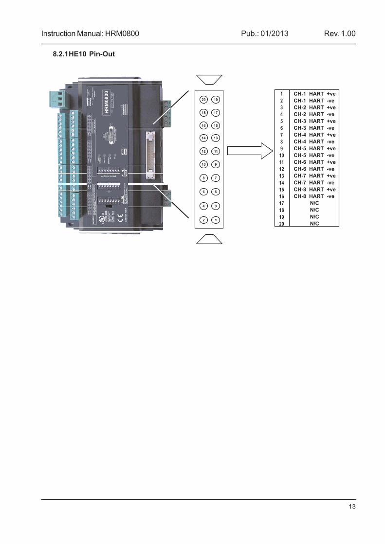
8.2.1HE10 Pin-Out
12
34
56
78
910
1112
1314
1516
1718
1920
1
2
3
4
5
6
7
8
9
10
11
12
13
14
15
16
17
18
19
20
CH-1 HART +ve
-
2
2 -
3
-
4
4
5
5
6
6
7
7
8
8
N/C
CH-1 HART ve
CH- HART +ve
CH- HART ve
CH- HART +ve
CH-3 HART ve
CH- HART +ve
CH- HART -ve
CH- HART +ve
CH- HART -ve
CH- HART +ve
CH- HART -ve
CH- HART +ve
CH- HART -ve
CH- HART +ve
CH- HART -ve
N/C
N/C
N/C
Instruction Manual: HRM0800 Pub.: 01/2013 Rev. 1.00
14
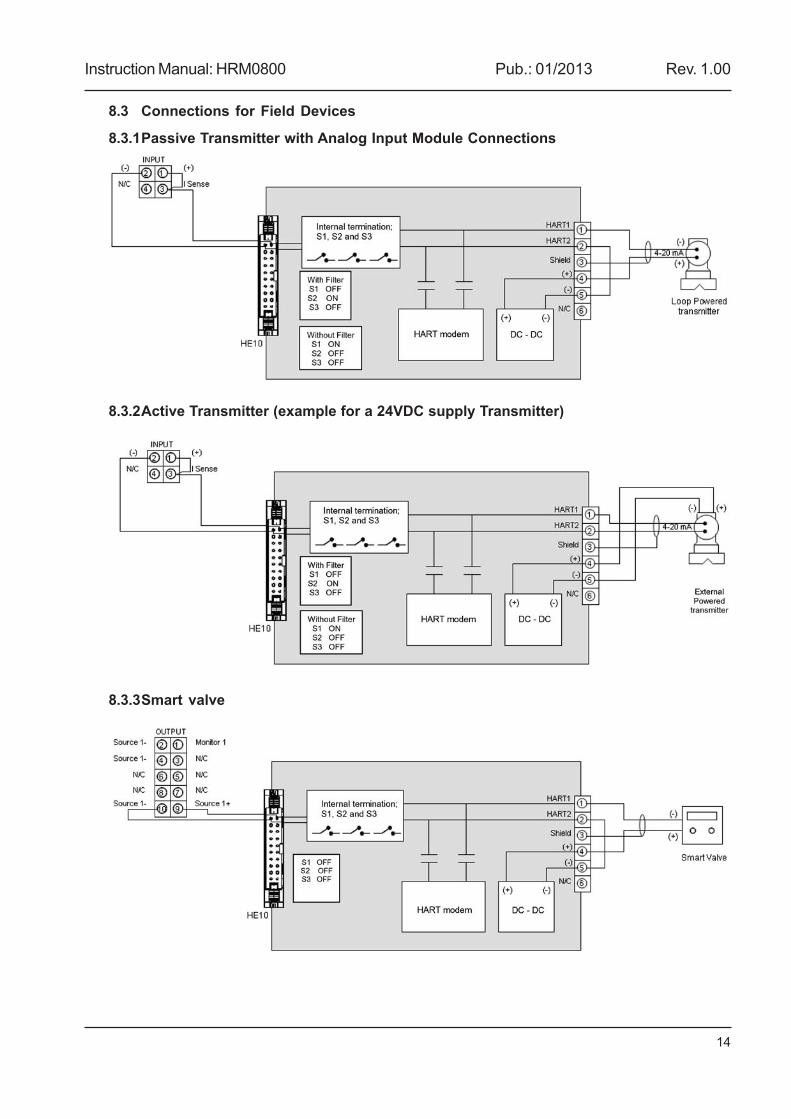
8.3 Connections for Field Devices
8.3.1Passive Transmitter with Analog Input Module Connections
8.3.2Active Transmitter (example for a 24VDC supply Transmitter)
8.3.3Smart valve
Instruction Manual: HRM0800 Pub.: 01/2013 Rev. 1.00
15
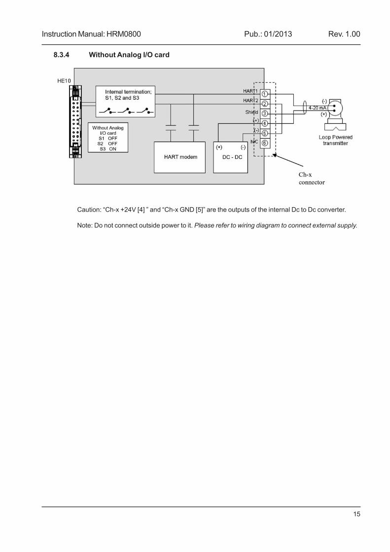
8.3.4 Without Analog I/O card
Caution: “Ch-x +24V [4] ” and “Ch-x GND [5]” are the outputs of the internal Dc to Dc converter.
Note: Do not connect outside power to it. Please refer to wiring diagram to connect external supply.
Instruction Manual: HRM0800 Pub.: 01/2013 Rev. 1.00
16
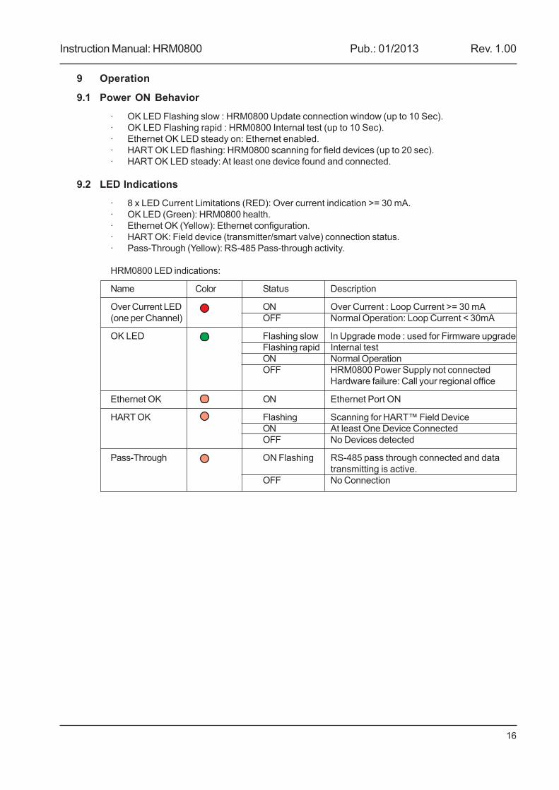
9 Operation
9.1 Power ON Behavior
· OK LED Flashing slow : HRM0800 Update connection window (up to 10 Sec).· OK LED Flashing rapid : HRM0800 Internal test (up to 10 Sec).· Ethernet OK LED steady on: Ethernet enabled.· HART OK LED flashing: HRM0800 scanning for field devices (up to 20 sec).· HART OK LED steady: At least one device found and connected.
9.2 LED Indications
· 8 x LED Current Limitations (RED): Over current indication >= 30 mA.· OK LED (Green): HRM0800 health.· Ethernet OK (Yellow): Ethernet configuration.· HART OK: Field device (transmitter/smart valve) connection status.· Pass-Through (Yellow): RS-485 Pass-through activity.
HRM0800 LED indications:
Name Color Status Description
Over Current LED ON Over Current : Loop Current >= 30 mA(one per Channel) OFF Normal Operation: Loop Current < 30mA
OK LED Flashing slow In Upgrade mode : used for Firmware upgradeFlashing rapid Internal testON Normal OperationOFF HRM0800 Power Supply not connected
Hardware failure: Call your regional office
Ethernet OK ON Ethernet Port ON
HART OK Flashing Scanning for HART™ Field DeviceON At least One Device ConnectedOFF No Devices detected
Pass-Through ON Flashing RS-485 pass through connected and datatransmitting is active.
OFF No Connection
Instruction Manual: HRM0800 Pub.: 01/2013 Rev. 1.00
17
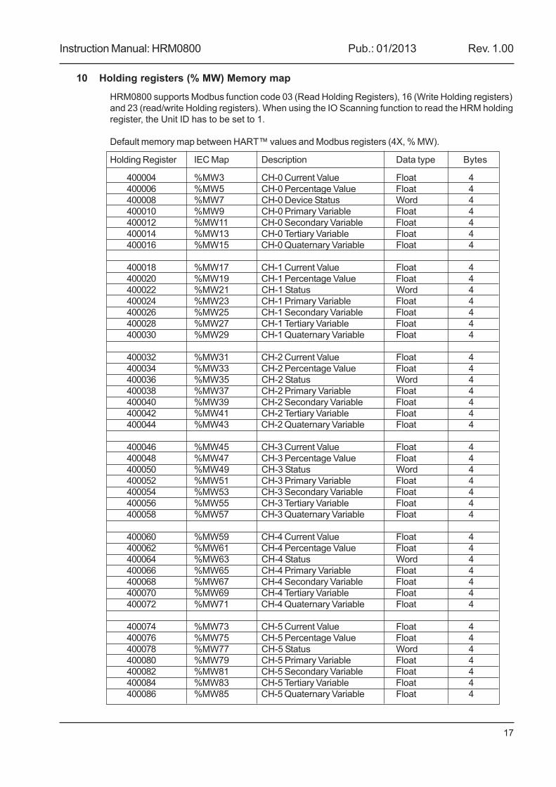
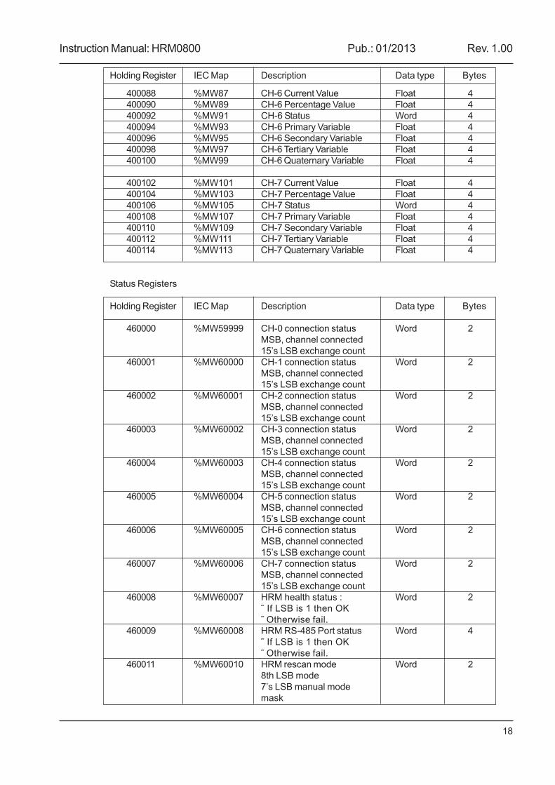
10 Holding registers (% MW) Memory map
HRM0800 supports Modbus function code 03 (Read Holding Registers), 16 (Write Holding registers)and 23 (read/write Holding registers). When using the IO Scanning function to read the HRM holdingregister, the Unit ID has to be set to 1.
Default memory map between HART™ values and Modbus registers (4X, % MW).
Holding Register IEC Map Description Data type Bytes
400004 %MW3 CH-0 Current Value Float 4400006 %MW5 CH-0 Percentage Value Float 4400008 %MW7 CH-0 Device Status Word 4400010 %MW9 CH-0 Primary Variable Float 4400012 %MW11 CH-0 Secondary Variable Float 4400014 %MW13 CH-0 Tertiary Variable Float 4400016 %MW15 CH-0 Quaternary Variable Float 4
400018 %MW17 CH-1 Current Value Float 4400020 %MW19 CH-1 Percentage Value Float 4400022 %MW21 CH-1 Status Word 4400024 %MW23 CH-1 Primary Variable Float 4400026 %MW25 CH-1 Secondary Variable Float 4400028 %MW27 CH-1 Tertiary Variable Float 4400030 %MW29 CH-1 Quaternary Variable Float 4
400032 %MW31 CH-2 Current Value Float 4400034 %MW33 CH-2 Percentage Value Float 4400036 %MW35 CH-2 Status Word 4400038 %MW37 CH-2 Primary Variable Float 4400040 %MW39 CH-2 Secondary Variable Float 4400042 %MW41 CH-2 Tertiary Variable Float 4400044 %MW43 CH-2 Quaternary Variable Float 4
400046 %MW45 CH-3 Current Value Float 4400048 %MW47 CH-3 Percentage Value Float 4400050 %MW49 CH-3 Status Word 4400052 %MW51 CH-3 Primary Variable Float 4400054 %MW53 CH-3 Secondary Variable Float 4400056 %MW55 CH-3 Tertiary Variable Float 4400058 %MW57 CH-3 Quaternary Variable Float 4
400060 %MW59 CH-4 Current Value Float 4400062 %MW61 CH-4 Percentage Value Float 4400064 %MW63 CH-4 Status Word 4400066 %MW65 CH-4 Primary Variable Float 4400068 %MW67 CH-4 Secondary Variable Float 4400070 %MW69 CH-4 Tertiary Variable Float 4400072 %MW71 CH-4 Quaternary Variable Float 4
400074 %MW73 CH-5 Current Value Float 4400076 %MW75 CH-5 Percentage Value Float 4400078 %MW77 CH-5 Status Word 4400080 %MW79 CH-5 Primary Variable Float 4400082 %MW81 CH-5 Secondary Variable Float 4400084 %MW83 CH-5 Tertiary Variable Float 4400086 %MW85 CH-5 Quaternary Variable Float 4
Instruction Manual: HRM0800 Pub.: 01/2013 Rev. 1.00
18
Holding Register IEC Map Description Data type Bytes
400088 %MW87 CH-6 Current Value Float 4400090 %MW89 CH-6 Percentage Value Float 4400092 %MW91 CH-6 Status Word 4400094 %MW93 CH-6 Primary Variable Float 4400096 %MW95 CH-6 Secondary Variable Float 4400098 %MW97 CH-6 Tertiary Variable Float 4400100 %MW99 CH-6 Quaternary Variable Float 4
400102 %MW101 CH-7 Current Value Float 4400104 %MW103 CH-7 Percentage Value Float 4400106 %MW105 CH-7 Status Word 4400108 %MW107 CH-7 Primary Variable Float 4400110 %MW109 CH-7 Secondary Variable Float 4400112 %MW111 CH-7 Tertiary Variable Float 4400114 %MW113 CH-7 Quaternary Variable Float 4
Status Registers
Holding Register IEC Map Description Data type Bytes
460000 %MW59999 CH-0 connection status Word 2MSB, channel connected15’s LSB exchange count
460001 %MW60000 CH-1 connection status Word 2MSB, channel connected15’s LSB exchange count
460002 %MW60001 CH-2 connection status Word 2MSB, channel connected15’s LSB exchange count
460003 %MW60002 CH-3 connection status Word 2MSB, channel connected15’s LSB exchange count
460004 %MW60003 CH-4 connection status Word 2MSB, channel connected15’s LSB exchange count
460005 %MW60004 CH-5 connection status Word 2MSB, channel connected15’s LSB exchange count
460006 %MW60005 CH-6 connection status Word 2MSB, channel connected15’s LSB exchange count
460007 %MW60006 CH-7 connection status Word 2MSB, channel connected15’s LSB exchange count
460008 %MW60007 HRM health status : Word 2� If LSB is 1 then OK� Otherwise fail.
460009 %MW60008 HRM RS-485 Port status Word 4� If LSB is 1 then OK� Otherwise fail.
460011 %MW60010 HRM rescan mode Word 28th LSB mode7’s LSB manual modemask
Instruction Manual: HRM0800 Pub.: 01/2013 Rev. 1.00
19
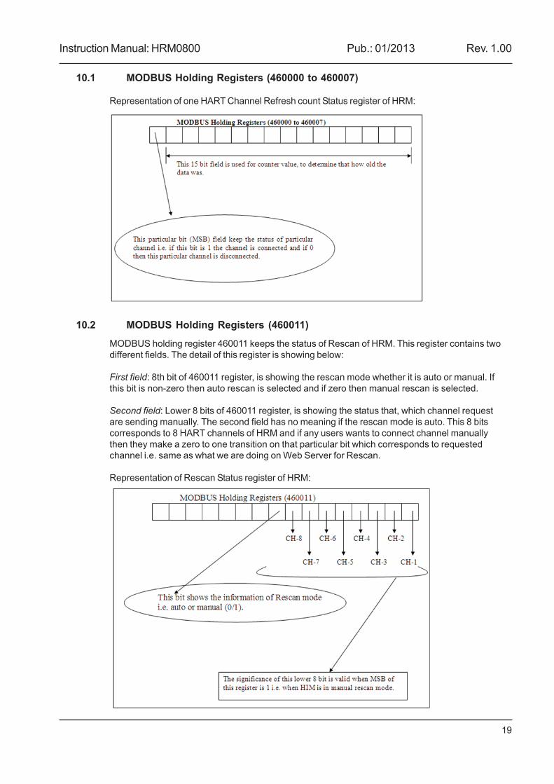
10.1 MODBUS Holding Registers (460000 to 460007)
Representation of one HART Channel Refresh count Status register of HRM:
10.2 MODBUS Holding Registers (460011)
MODBUS holding register 460011 keeps the status of Rescan of HRM. This register contains twodifferent fields. The detail of this register is showing below:
First field: 8th bit of 460011 register, is showing the rescan mode whether it is auto or manual. Ifthis bit is non-zero then auto rescan is selected and if zero then manual rescan is selected.
Second field: Lower 8 bits of 460011 register, is showing the status that, which channel requestare sending manually. The second field has no meaning if the rescan mode is auto. This 8 bitscorresponds to 8 HART channels of HRM and if any users wants to connect channel manuallythen they make a zero to one transition on that particular bit which corresponds to requestedchannel i.e. same as what we are doing on Web Server for Rescan.
Representation of Rescan Status register of HRM:
Instruction Manual: HRM0800 Pub.: 01/2013 Rev. 1.00
20
11 Web Server
11.1 Ethernet Setup
11.1.1 Static IP Address
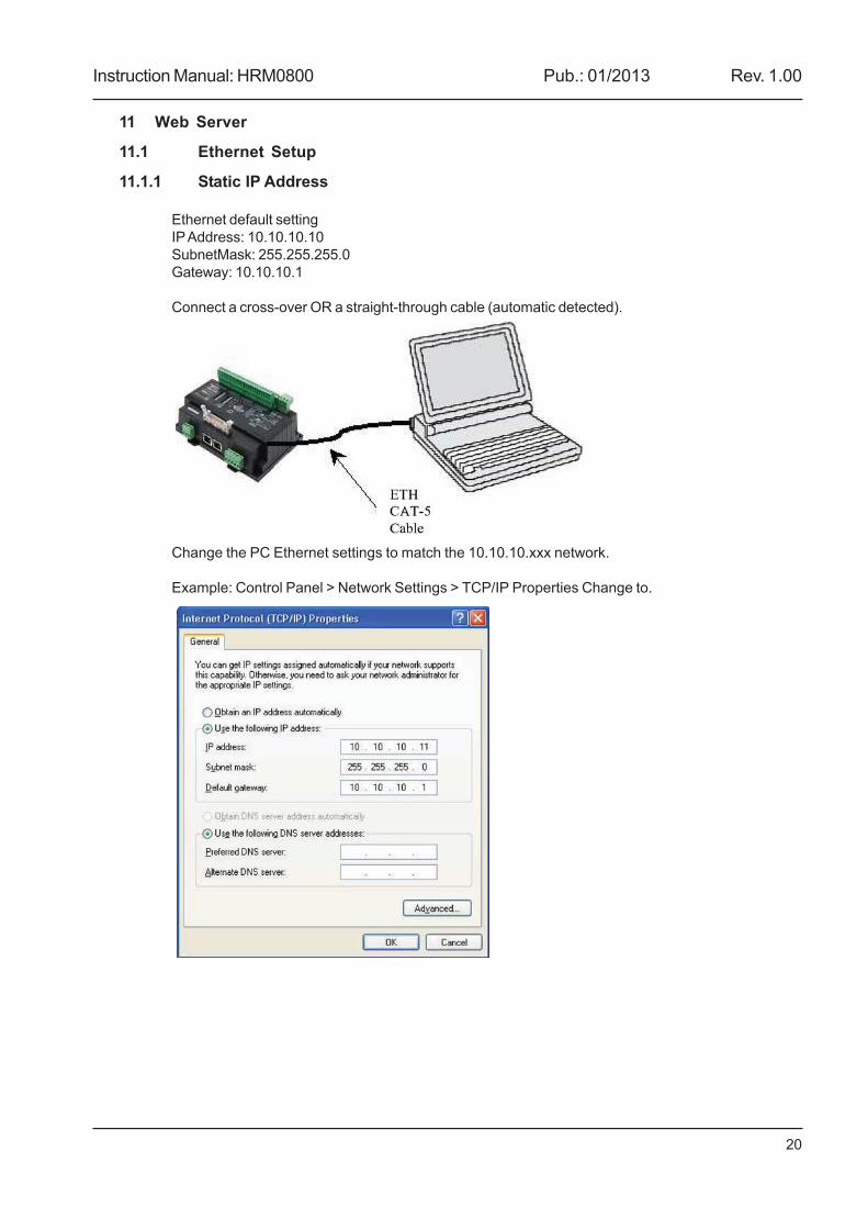
Ethernet default settingIP Address: 10.10.10.10SubnetMask: 255.255.255.0Gateway: 10.10.10.1
Connect a cross-over OR a straight-through cable (automatic detected).
Change the PC Ethernet settings to match the 10.10.10.xxx network.
Example: Control Panel > Network Settings > TCP/IP Properties Change to.
Instruction Manual: HRM0800 Pub.: 01/2013 Rev. 1.00
21
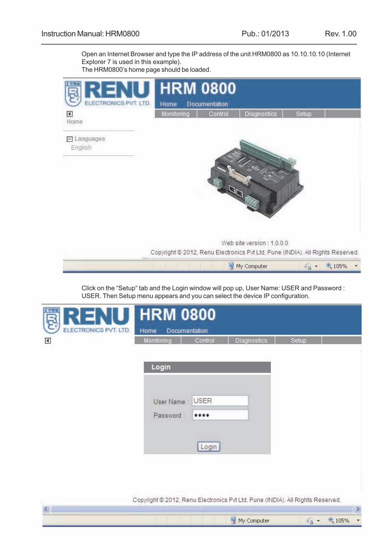
Open an Internet Browser and type the IP address of the unit HRM0800 as 10.10.10.10 (InternetExplorer 7 is used in this example).The HRM0800’s home page should be loaded.
Click on the “Setup“ tab and the Login window will pop up, User Name: USER and Password :USER. Then Setup menu appears and you can select the device IP configuration.
Instruction Manual: HRM0800 Pub.: 01/2013 Rev. 1.00
22
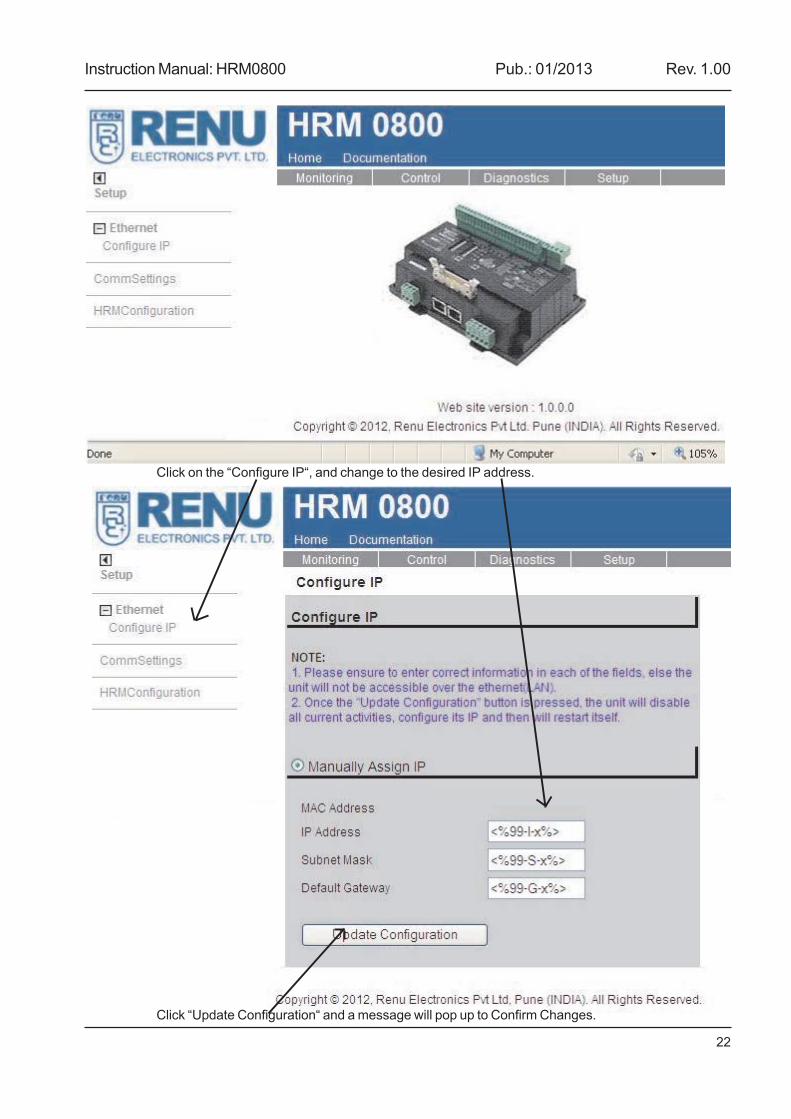
Click on the “Configure IP“, and change to the desired IP address.
Click “Update Configuration“ and a message will pop up to Confirm Changes.
Instruction Manual: HRM0800 Pub.: 01/2013 Rev. 1.00
23
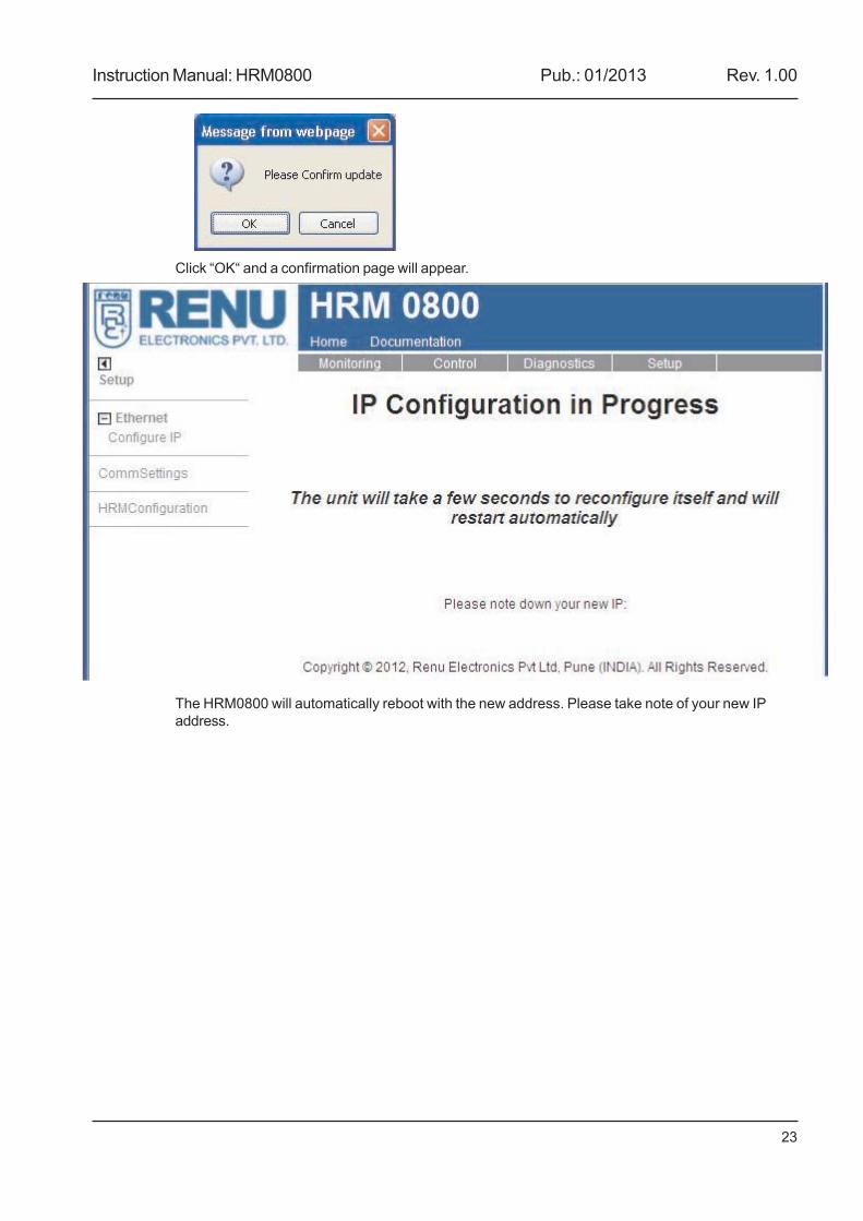
Click “OK“ and a confirmation page will appear.
The HRM0800 will automatically reboot with the new address. Please take note of your new IPaddress.
Instruction Manual: HRM0800 Pub.: 01/2013 Rev. 1.00
24
11.2 Embedded Web Pages
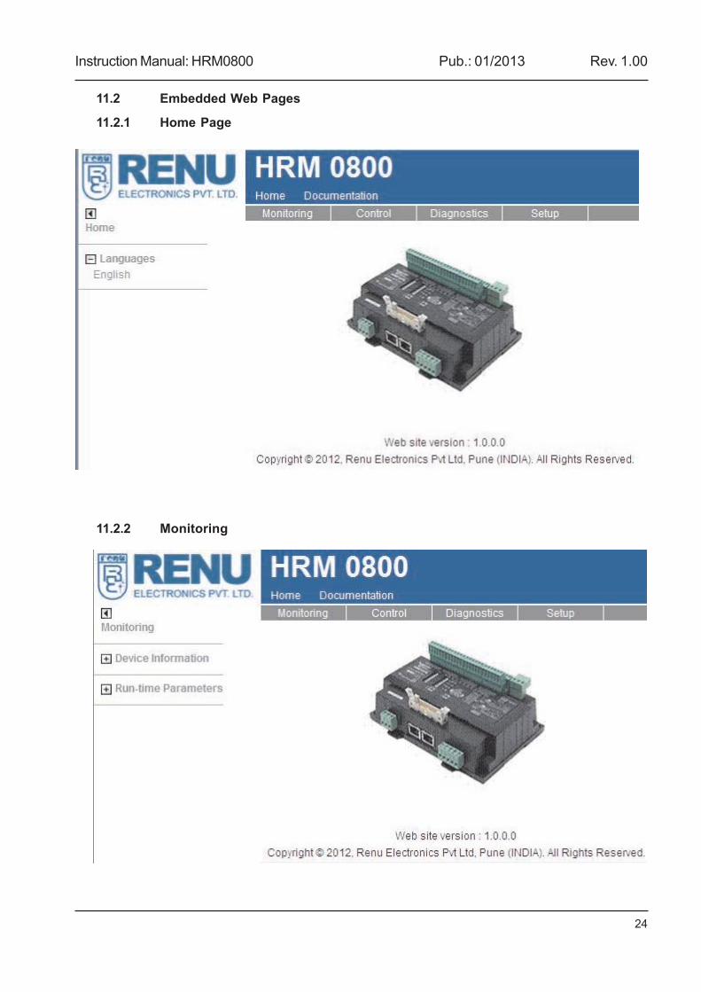
11.2.1 Home Page
11.2.2 Monitoring
Instruction Manual: HRM0800 Pub.: 01/2013 Rev. 1.00
25
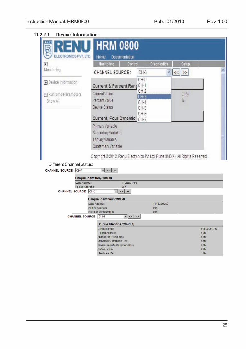
11.2.2.1 Device Information
Different Channel Status:
Instruction Manual: HRM0800 Pub.: 01/2013 Rev. 1.00
26
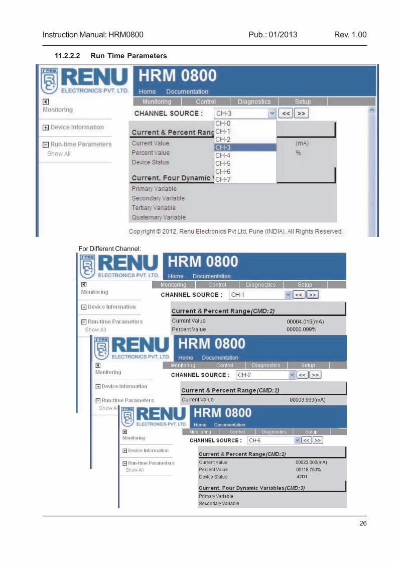
11.2.2.2 Run Time Parameters
For Different Channel:
00000.099%
00003.999(mA)
00023.000(mA)
00118.750%
42D1
Instruction Manual: HRM0800 Pub.: 01/2013 Rev. 1.00
27
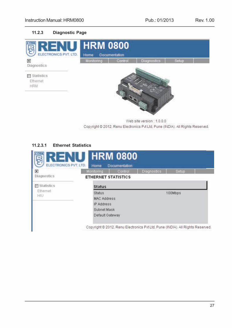
11.2.3 Diagnostic Page
11.2.3.1 Ethernet Statistics
Instruction Manual: HRM0800 Pub.: 01/2013 Rev. 1.00
28
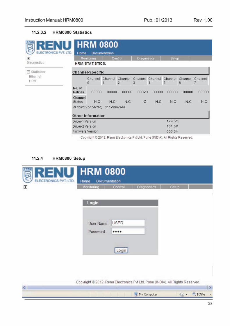
11.2.3.2 HRM0800 Statistics
11.2.4 HRM0800 Setup
00000 00000 00000 00029 00000 00000 00000 00000
-N.C- -N.C- -N.C- -C- -N.C- -N.C- -N.C- -N.C-
129.3Q
131.3P
003.3H
Instruction Manual: HRM0800 Pub.: 01/2013 Rev. 1.00
29
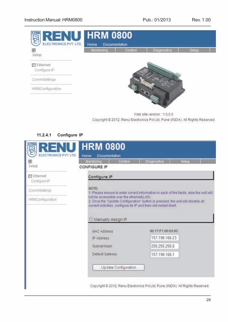
11.2.4.1 Configure IP
00:17:F1:00:03:0C
Instruction Manual: HRM0800 Pub.: 01/2013 Rev. 1.00
30
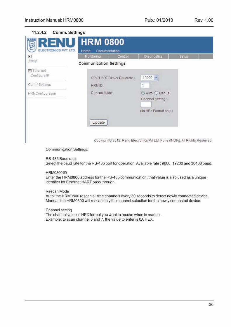
11.2.4.2 Comm. Settings
Communication Settings:
RS-485 Baud rateSelect the baud rate for the RS-485 port for operation. Available rate : 9600, 19200 and 38400 baud.
HRM0800 IDEnter the HRM0800 address for the RS-485 communication, that value is also used as a uniqueidentifier for Ethernet HART pass through.
Rescan ModeAuto: the HRM0800 rescan all free channels every 30 seconds to detect newly connected device.Manual: the HRM0800 will rescan only the channel selection for the newly connected device.
Channel settingThe channel value in HEX format you want to rescan when in manual.Example: to scan channel 5 and 7, the value to enter is 0A HEX.
Instruction Manual: HRM0800 Pub.: 01/2013 Rev. 1.00
31
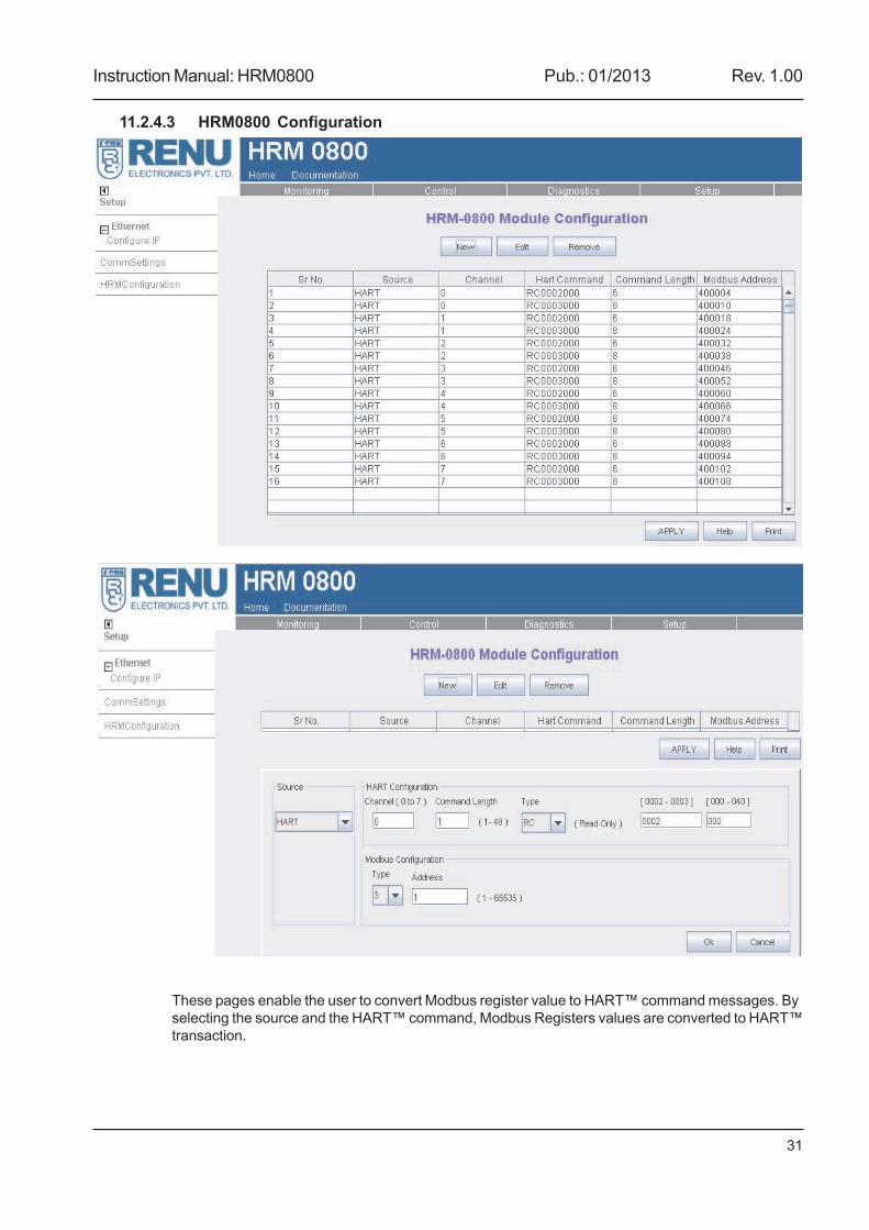
11.2.4.3 HRM0800 Configuration
These pages enable the user to convert Modbus register value to HART™ command messages. Byselecting the source and the HART™ command, Modbus Registers values are converted to HART™transaction.
Instruction Manual: HRM0800 Pub.: 01/2013 Rev. 1.00
32
Once configured the Modbus/TCP host is able to read and write to these registers and establishcommunication to retrieve or write critical HART™ data to and from the field device.HRM0800 Module Configuration
SourceSelect HART for a read command or Modbus TCP for a write command.
HART Configuration
Channel (0 to 7)Enter the channel you want to communicate with.
Command lengthEnter the length of the HART™ command (16 bits register).
TypeUC: Universal command.CP: Common practice command.DR: Device specific read command.DW: Device specific write command.RC: Read Command.
Note: For the complete Command definitions, please refer to http://www.hartcomm.org
HART™ commands are divided in 3 types, the Universal Command, the Common Practice and theDevice Specific Command. For HRM0800, Device Specific Commands were divided in two groups,the DR for the read and the DW for the Write.
To facilitate the Modbus register mapping for Universal command 2 and 3, RC 2 and RC 3commands were created. These commands have been formatted to fit Modbus register.
RC 2 response: Registers 0-1: Current (mA) floating point formattedRegisters 2-3: Percentage of range floating point formattedRegisters 4-5: Device status
RC 3 response: Registers 0-1: Primary variable floating point formattedRegisters 2-3: Secondary variable floating point formattedRegisters 4-5: Third variable floating point formattedRegisters 6-7: Fourth variable floating point formatted
[xxx-xxx]Enter the HART™ command number,
- UC range from 0 to 30.- CP range from 32 to 121- DX range from 128 to 999
NOTE: Please refer to instrument manual for the complete list of supported HART™ commands.
Modbus Configuration
TypeSelect register and type the command or respond for that HART™ command.
Instruction Manual: HRM0800 Pub.: 01/2013 Rev. 1.00
33
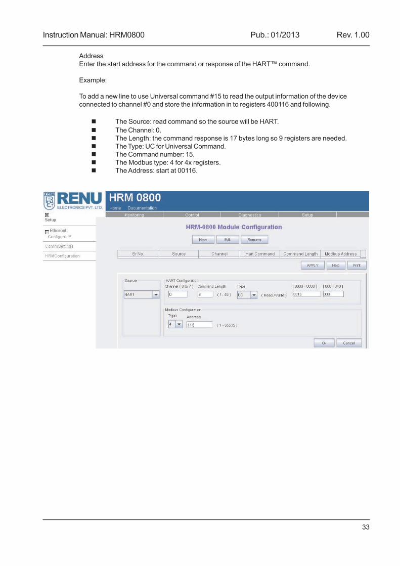
AddressEnter the start address for the command or response of the HART™ command.
Example:
To add a new line to use Universal command #15 to read the output information of the deviceconnected to channel #0 and store the information in to registers 400116 and following.
The Source: read command so the source will be HART.The Channel: 0.The Length: the command response is 17 bytes long so 9 registers are needed.The Type: UC for Universal Command.The Command number: 15.The Modbus type: 4 for 4x registers.The Address: start at 00116.
Instruction Manual: HRM0800 Pub.: 01/2013 Rev. 1.00
34
Appendix A: Installation recommendations
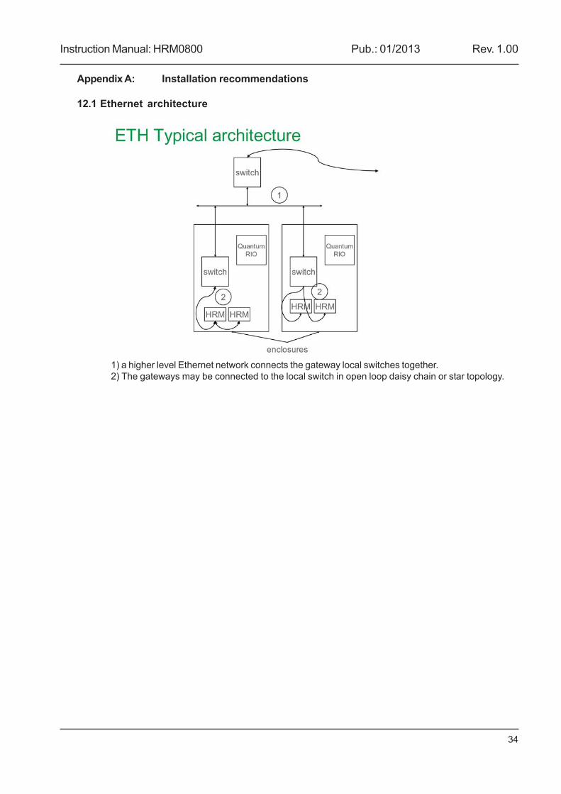
12.1 Ethernet architecture
1) a higher level Ethernet network connects the gateway local switches together.2) The gateways may be connected to the local switch in open loop daisy chain or star topology.
Instruction Manual: HRM0800 Pub.: 01/2013 Rev. 1.00
35
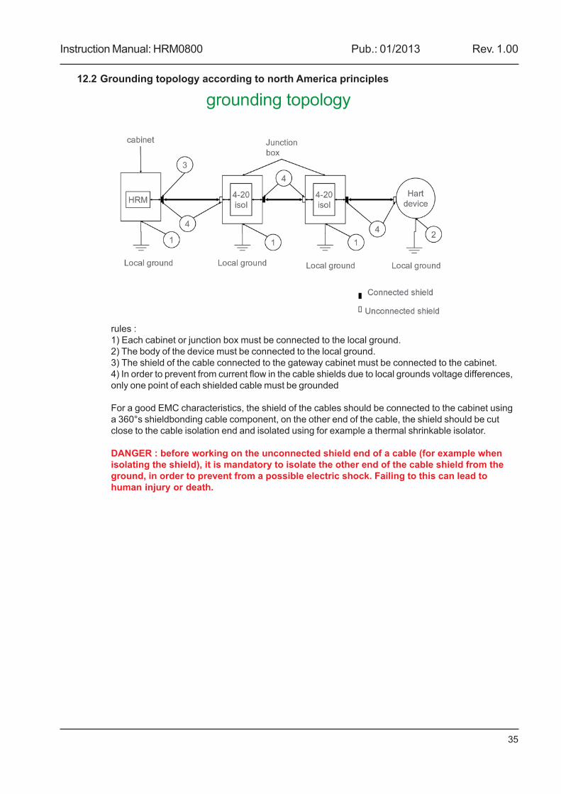
12.2 Grounding topology according to north America principles
rules :1) Each cabinet or junction box must be connected to the local ground.2) The body of the device must be connected to the local ground.3) The shield of the cable connected to the gateway cabinet must be connected to the cabinet.4) In order to prevent from current flow in the cable shields due to local grounds voltage differences,only one point of each shielded cable must be grounded
For a good EMC characteristics, the shield of the cables should be connected to the cabinet usinga 360°s shieldbonding cable component, on the other end of the cable, the shield should be cutclose to the cable isolation end and isolated using for example a thermal shrinkable isolator.
DANGER : before working on the unconnected shield end of a cable (for example whenisolating the shield), it is mandatory to isolate the other end of the cable shield from theground, in order to prevent from a possible electric shock. Failing to this can lead tohuman injury or death.
A manual revision code appears to the bottom of this manual and on the front cover of themanual.
/i
Doc. No.: UMAN/HRM0800Ver.: 1.00
The following table outlines the changes made to the manual during each revision. The pagenumbers of a revision refer to the previous version.
/i
Revision code Date Revised content
1.00 18.01.13 First Draft
REVISION HISTORY