hpsdr – griffin · hpsdr – griffin or ... of a tv transmitter. • using chirp radar we no...
TRANSCRIPT

1
HPSDR – Griffin or
A Whisper & a Chirp
Phil Harman VK6APH
Dayton Hamvention – 20th May 2011

2
Overview
• Griffin is a High Performance Software Defined Radio (HPSDR) project supported by T.A.P.R.
• Griffin provides the driver stage for an HF/VHF beacon
• The bock diagram is as follows:


Griffin - Features
• Supports all types of Beacon modulation (CW, WSPR,RTTY etc) plus any future mode
• Simultaneous beacons, each with different modulation,on same or multiple bands
• GPS locked so high frequency and time accuracy• Internet access for remote control and configuration• New code can be uploaded via Ethernet/Internet• Uses high gate count FPGA so room for future upgrades

5
Griffin – new features
• 6m Band operators facing loss of early warning propagation indicators
• Low Band VHF TV transmitters being removed due to introduction of Digital TV
• Features of TV transmitters:– Well located– High power (500kW ERP)– 24 hour operation– Stable and know frequencies

6
Griffin – new features
TV9 – 37kW – 48.26MHzTV7 – 50kW - 48.26MHzM3 - 37kW - 48.24MHz
TH1 – 40kW - 48.25MHz
RTM1-100kW – 48.23MHz

7
Griffin – new features
• How can we provide alternatives as these TV transmitters are removed from service?
• Three things under our control:– Beacon Power– Beacon Bandwidth– Beacon Time

8
Griffin – new features
• Power – 10 to 50W is typical, cost and FCC regs• Bandwidth – in VK beacons are 2kHz spacing• Time – Most beacons run 24 hours• What other systems have power restrictions?
– RADAR – 1MW ERP for a land based system– 10kW ERP for plane and boat systems – So how do RADAR systems solve the power
problem?
9
RADAR - Chirp
• RADAR systems use a technique called ‘Chirp’ to increase the ‘Effective’ Radiated Power.
• Rather than transmit a steady carrier they sweep it over a frequency range in a specific time

RADAR - Chirp
10

RADAR - Chirp• Effective increase in Radiated Power is
ERP ∞ Bandwidth (Hz) x Time (seconds)• So, sweep over 1kHz in one second = 1000 or 30dB• Easy to do with an Analog beacon and trivial using
Digital Signal Processing e.g. Griffin!• Receiver can be a conventional SSB receiver + sound
card or DDC e.g. HPSDR – Mercury receiver.• Receiver uses a ‘Matched Filter’, implement using a PC• Receiver needs to know exactly when the Beacon Chirp
started.• Use 1PPS from GPS receiver to synchronize Beacon and
receiver

12
VK3OE – Chirp RADAR
Block diagram
Tx
Rx
GPS
GPS
1PPS
1PPS

RADAR - Chirp
• Matlab simulation
13

RADAR - Chirp
• Matlab simulation
14

RADAR - Chirp
15
Frequency
Frequency
dB
Del
ay
Matched Filter
FFT
FFT
IFFTsignal
chirp

16
RADAR-Chirp
• Test – VK6HK to VK3OE on 20m. 2,750km path between Perth and Melbourne.
• Signal at VK3OE not audible in 2.4kHz bandwidth.
• Decoded using PC Software ‘Spectrum Lab’ by DL4YHF.

RADAR - Chirp
17
30dB

18
Griffin - Chirp
• So we have a beacon with better than WSPR performance (but we trade bandwidth for time).
• We can juggle Bandwidth and Time for higher gain e.g. 2kHz over 10 seconds gives 43dB (10w = 200kW ERP).
• If we chirp for 1 second but integrate over a minute we gain 17dB, total of 50dB.
• What else can we use the Chirp signal for?• Perhaps a RADAR
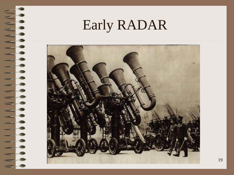
Early RADAR
19

Home Brew?
20

21
RADARBackscatter – Principle of Operation
Main signal reflected forward
Part of signal scattered by ground or sea irregularities – some returns
Rx
22
RADAR - Chirp
• For a RADAR we run full power into a high gain directional antenna
• We use one station as the transmitter and another as the receiver. Transmit was on 6m from VK3OE and Receive at VK3AUU some 65km apart.
• Receiver antenna 15 elements on a 24m boom, 14dBd gain.

23
RADAR

RADAR
• Analysis of all the RADAR images done by Roger Harrison, VK2ZRH.
• Internationally acknowledged expert in propagation research and ionosonde development
• Ex Australian Ionospheric Prediction Service (IPS) www.ips.gov.au
24
25
RADAR

26
Multi-hop Sporadic E

27
Multi-hop Sporadic E

28
Multi-hop Sporadic E
IPS

Multi-hop Sporadic E
• Multi-hop Sporadic E confirmed via Norfolk Island Ionogram
• VK3 worked T35A
29

Es and TEP
30

Results
• Hundreds of tests over 12 months indicate that the VK3OE system is 100% reliable & repeatable.
• Initial tests over 12 months ago.• Current status.
31

Remote Site
• VK3OE, Solar Powered, Internet access via 3G
32

Chirp RADAR – 20m• Transmit, 50 watts, vertical, Receive, 2 el Yagi, 142km from the transmit. 20 seconds averaged. 330 degrees. • Image is is rather more complex than it first appears; it shows 3-hop Es and 1-hop F2 - the latter falling between the
2nd and 3rd Es hops. It must have been a busy evening in the ionosphere over Western-NSW and the NT!
33

Chirp RADAR – 20m• As previous 200 degrees 10:00 UTC, 20 April 2011.• Image shows mixed 1 & 2-hop F2. The Hobart ionogram shows the F2 layer at 200 km h'F2 and foF2 of 5.2 MHz,
the MUF for the path would have been about 20 MHz
34

Chirp RADAR – 20m
• We can produce a PPI map over 360° by moving the receive antenna.
• The following plot was taken on 22nd & 23rd
April 2011.• A set of 10 chirps was sent in each of 36
directions and the results combined• RADAR returns are evident at up to 10dB S/N
out to 15,000km• Range markings are at 1500km spacing
35

Chirp RADAR – 20m• 22 April 2011, 10:30UTC (90 to 350 degrees) and 23 April 2011, 10:30UTC
(350 to 90 degrees).
36

Summary
• A Chirp beacon will provide the equivalent system ERP of a TV Transmitter.
• Using Chirp RADAR we no longer need a signal at the other end in order to check if a path is open.
• Chirp RADAR can be used on any Amateur Band to check propagation in a specific direction.
• Open source software will be available. Hermann, DL3HVH, is developing a PC + CUDA application.
• Potential to build well sighted, Internet connected, remote Beacon and RADAR stations.
• High potential for discovering new propagation modes. 37

Acknowledgements
• Andrew, VK3OE, original idea• David, VK3AUU, receiving station• Roger, VK2ZRH, analysis & slides
38

Questions
?39