hpe edgeline el4000 system user guide - national … edgeline el4000 system user guide part number:...
TRANSCRIPT

HPE Edgeline EL4000 System UserGuide
Part Number: 868755-002Published: May 2017Edition: 2
AbstractThis document is for the person who installs, administers, and troubleshoots servers andstorage systems. Hewlett Packard Enterprise assumes you are qualified in the servicing ofcomputer equipment and trained in recognizing hazards in products with hazardous energylevels.

© 2017 Hewlett Packard Enterprise Development LP
NoticesThe information contained herein is subject to change without notice. The only warranties for HewlettPackard Enterprise products and services are set forth in the express warranty statements accompanyingsuch products and services. Nothing herein should be construed as constituting an additional warranty.Hewlett Packard Enterprise shall not be liable for technical or editorial errors or omissions containedherein.
Confidential computer software. Valid license from Hewlett Packard Enterprise required for possession,use, or copying. Consistent with FAR 12.211 and 12.212, Commercial Computer Software, ComputerSoftware Documentation, and Technical Data for Commercial Items are licensed to the U.S. Governmentunder vendor's standard commercial license.
Links to third-party websites take you outside the Hewlett Packard Enterprise website. Hewlett PackardEnterprise has no control over and is not responsible for information outside the Hewlett PackardEnterprise website.
AcknowledgmentsIntel®, Itanium®, Pentium®, Intel Inside®, and the Intel Inside logo are trademarks of Intel Corporation inthe United States and other countries.
Microsoft® and Windows® are either registered trademarks or trademarks of Microsoft Corporation in theUnited States and/or other countries.
Linux™is the registered trademark of Linus Torvalds in the U.S. and other countries.
SD™ and microSD™are trademarks or registered trademarks of SD-3C in the United States, othercountries or both.
NVIDIA™is a trademark of NVIDIA Corporation in the U.S. and other countries.
Contents
Component identification.......................................................................6Base configurations...................................................................................................................... 6
PCIe configuration..............................................................................................................6Front panel components..........................................................................................6Front panel LEDs and buttons.................................................................................7Rear panel components.......................................................................................... 8System board components (PCIe).......................................................................... 8Cartridge slot identification...................................................................................... 9
PXIe configuration..............................................................................................................9Front panel components..........................................................................................9Front panel LEDs and buttons...............................................................................10Rear panel components.........................................................................................11Rear panel LEDs and buttons................................................................................11System board components (PXIe)........................................................................ 12Cartridge slot identification.................................................................................... 12
Operations............................................................................................. 14Install an AC power supply......................................................................................................... 14Install the DC power supply........................................................................................................ 14Install a power supply blank........................................................................................................18Power down the system..............................................................................................................19Power up the system.................................................................................................................. 19Mount the system........................................................................................................................19Remove the access panel...........................................................................................................20
Removing the PCIe access panel.................................................................................... 20Removing the PXIe access panel.................................................................................... 20
Remove the fixed top cover........................................................................................................ 21Removing the fixed top cover of the PCIe system........................................................... 21Removing the fixed front top cover of the PXIe system................................................... 21Removing the fixed rear top cover of the PXIe system.................................................... 22
Install the fans.............................................................................................................................22Install the cartridge......................................................................................................................23
Setup...................................................................................................... 25Optional services.........................................................................................................................25Optimum environment.................................................................................................................25
Space and airflow requirements.......................................................................................25Temperature requirements............................................................................................... 25Power requirements......................................................................................................... 25
Installing hardware options ........................................................................................................ 26Registering the product...............................................................................................................26
Hardware options installation..............................................................27Installing the short extension rail kit............................................................................................ 27Installing the full extension rail kit with cable management arm................................................. 27
Contents 3
Configuration.........................................................................................28Networking in the chassis........................................................................................................... 28Accessing the System Utilities menu.......................................................................................... 29Viewing or updating the DHCP address using the serial console cable..................................... 30Finding the IP address through DHCP........................................................................................30Setting the static IP address using the serial console cable....................................................... 31
Software and configuration utilities.................................................... 33Product QuickSpecs................................................................................................................... 33Supported operating systems and drivers matrix .......................................................................33HPE iLO...................................................................................................................................... 33
Active Health System....................................................................................................... 33Active Health System data collection.................................................................... 33Active Health System log.......................................................................................34
iLO RESTful API support..................................................................................................34Integrated Management Log............................................................................................ 34
HPE Insight Cluster Management Utility.....................................................................................34HPE Edgeline Component Pack................................................................................................. 35
HP Smart Update Manager..............................................................................................35UEFI System Utilities.................................................................................................................. 35
Using UEFI System Utilities............................................................................................. 35Flexible boot control......................................................................................................... 36Restoring and customizing configuration settings............................................................36Secure Boot configuration................................................................................................37Embedded UEFI shell...................................................................................................... 37Embedded Diagnostics option......................................................................................... 37iLO RESTful API support for UEFI................................................................................... 38Re-entering the server serial number and product ID...................................................... 38
Troubleshooting.................................................................................... 39HPE Edgeline Troubleshooting Guide........................................................................................ 39
Battery....................................................................................................40Battery specifications.................................................................................................................. 40Replace the system battery........................................................................................................ 40
Warranty and regulatory information..................................................42Warranty information...................................................................................................................42Regulatory information................................................................................................................42
Safety and regulatory compliance....................................................................................42Belarus Kazakhstan Russia marking............................................................................... 42Turkey RoHS material content declaration.......................................................................43Ukraine RoHS material content declaration..................................................................... 43
Electrostatic discharge.........................................................................44Preventing electrostatic discharge.............................................................................................. 44Grounding methods to prevent electrostatic discharge...............................................................44
4 Contents

Specifications........................................................................................45Product QuickSpecs................................................................................................................... 45Environmental specifications ..................................................................................................... 45
Environmental specifications-system components support matrix...................................46Mechanical specifications........................................................................................................... 47Power supply specifications........................................................................................................47
HPE 800W Flex Slot Platinum Hot Plug Power Supply................................................... 47HPE 800W Flex -48VDC Hot Plug Power Supply............................................................48
PXI/PXIe specifications...............................................................................................................49Electrical load regulation specifications........................................................................... 49Chassis cooling specifications......................................................................................... 49Pollution specifications.....................................................................................................49Shock and vibration specifications................................................................................... 49Acoustic emission specifications .....................................................................................49System synchronization clock specifications................................................................... 50
Websites................................................................................................ 52
Support and other resources...............................................................53Accessing Hewlett Packard Enterprise Support......................................................................... 53
Information to collect........................................................................................................ 53Accessing updates......................................................................................................................53Customer self repair....................................................................................................................53Remote support.......................................................................................................................... 54
Acronyms and abbreviations...............................................................55
Documentation feedback..................................................................... 57
Contents 5

Component identificationBase configurations
The HPE Edgeline EL4000 System comes in the following configurations:
• HPE Edgeline EL4000 4x10GbE 2xQSFP+ PassThru System
Supports 1 to 4 full-height, half-length PCIe cards. The core network is pass-through. A separate 1GRJ-45 network port is provided for access to the iLO management network.
• HPE Edgeline EL4000 10GbE 2xSFP+ Switch System
Supports 1 to 4 full-height, half-length PCIe cards. The core network is Layer 2 switched. A separate1G RJ-45 network port is provided for access to the iLO management network.
• HPE Edgeline EL4000 10GbE 2xSFP+ Switch PXIe System
Supports 1 to 4 PXIe modules. The core network is Layer 2 switched. A separate 1G RJ-45 networkport is provided for access to the iLO management network.
For identification of system components, see the following:
• PCIe configuration on page 6• PXIe configuration on page 9
PCIe configuration
Front panel components
Item Description
1 Cartridge 1
2 Cartridge 2
3 Cartridge 3
4 Cartridge 4
6 Component identification
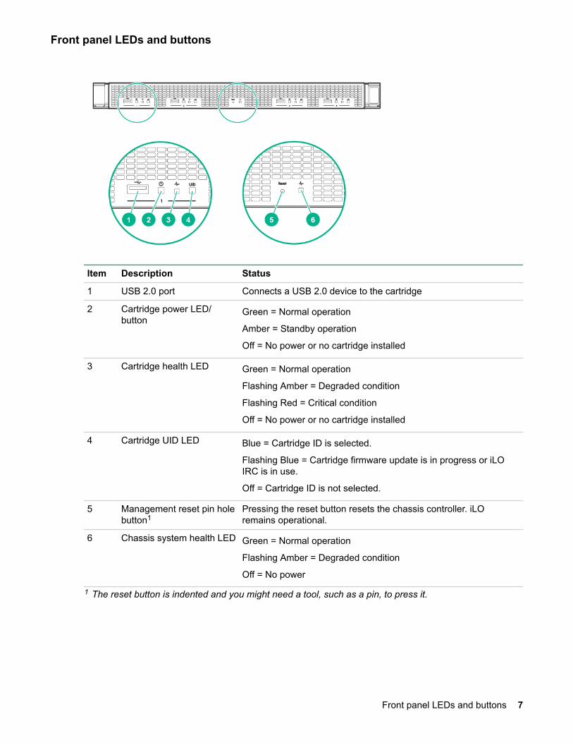
Front panel LEDs and buttons
Item Description Status
1 USB 2.0 port Connects a USB 2.0 device to the cartridge
2 Cartridge power LED/button
Green = Normal operation
Amber = Standby operation
Off = No power or no cartridge installed
3 Cartridge health LED Green = Normal operation
Flashing Amber = Degraded condition
Flashing Red = Critical condition
Off = No power or no cartridge installed
4 Cartridge UID LED Blue = Cartridge ID is selected.
Flashing Blue = Cartridge firmware update is in progress or iLOIRC is in use.
Off = Cartridge ID is not selected.
5 Management reset pin holebutton1
Pressing the reset button resets the chassis controller. iLOremains operational.
6 Chassis system health LED Green = Normal operation
Flashing Amber = Degraded condition
Off = No power
1 The reset button is indented and you might need a tool, such as a pin, to press it.
Front panel LEDs and buttons 7
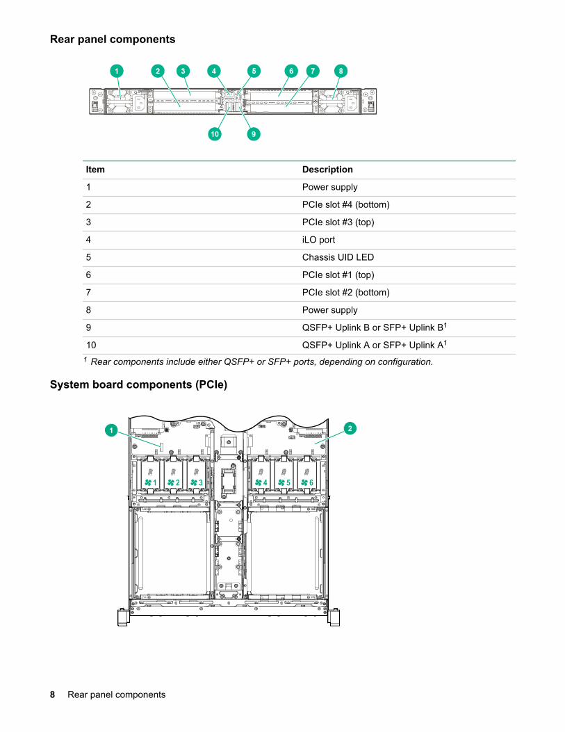
Rear panel components
Item Description
1 Power supply
2 PCIe slot #4 (bottom)
3 PCIe slot #3 (top)
4 iLO port
5 Chassis UID LED
6 PCIe slot #1 (top)
7 PCIe slot #2 (bottom)
8 Power supply
9 QSFP+ Uplink B or SFP+ Uplink B1
10 QSFP+ Uplink A or SFP+ Uplink A1
1 Rear components include either QSFP+ or SFP+ ports, depending on configuration.
System board components (PCIe)
21
1 2 3 4 5 6
8 Rear panel components

Item Description
1 System battery
2 System board
Cartridge slot identification
3 4
1 2
Item Description
1 Left side, top—Cartridge 1
2 Left side, bottom—Cartridge 2
3 Right side, top—Cartridge 3
4 Right side, bottom—Cartridge 4
PXIe configuration
Front panel components
1 2 8 93 4 5 6 7
Item Description
1 Cartridge 1
2 Cartridge 2
3 10 MHz REF OUT clock
4 SFP+ Uplink A connector
5 SFP+ Uplink B connector
6 10 MHz REF IN clock
7 iLO connector
Table Continued
Cartridge slot identification 9

Item Description
8 Cartridge 3
9 Cartridge 4
Front panel LEDs and buttons
41 2 3 5 6
Item Description Status
1 USB 2.0 port Connects a USB 2.0 device to the cartridge
2 Cartridge power LED/button
Green = Normal operation
Amber = Standby operation
Off = No power or no cartridge installed
3 Cartridge health LED Green = Normal operation
Flashing Amber = Degraded condition
Flashing Red = Critical condition
Off = No power or no cartridge installed
4 Cartridge UID LED Blue = Cartridge ID is selected.
Flashing Blue = Cartridge firmware update is in progress or iLOIRC is in use.
Off = Cartridge ID is not selected.
5 Management reset pin holebutton1
Pressing the reset button resets the chassis controller. iLOremains operational.
6 Chassis system health LED Green = Normal operation
Flashing Amber = Degraded condition
Off = No power
1 The reset button is indented and you might need a tool, such as a pin, to press it.
10 Front panel LEDs and buttons

Rear panel components
2
1 62 3 4 5
Item Description
1 Power supply 1
2 PXIe slot 4
3 PXIe slot 5
4 PXIe slot 3
5 PXIe slot 2
6 Power supply 2
Rear panel LEDs and buttons
2
1 32
Item Description
1 Power supply 1 LED
2 Chassis UID LED
3 Power supply 2 LED
Rear panel components 11

System board components (PXIe)
1 32
1 2 3 47
5 6
Item Description
1 System board
2 DIP Switch
3 System battery
DIP switch
Position Default Function
S1 Off • Off = Fan normal mode• On = Fan high mode
Cartridge slot identification
3 4
1 2
Item Description
1 Left side, top—Cartridge 1
2 Left side, bottom—Cartridge 2
Table Continued
12 System board components (PXIe)
Item Description
3 Right side, top—Cartridge 3
4 Right side, bottom—Cartridge 4
Component identification 13

OperationsInstall an AC power supplyProcedure
1. Align the power supply to the system.2. Insert the power supply until it locks in place.
3. Connect the power cord and tie wrap the cable.
You must press the Power On/Off button twice to power on the system.
Install the DC power supplyProcedure
1. Remove the ring tongue from the top of the power supply.
2. Crimp the ring tongue to the ground cable from the -48V power source.
14 Operations
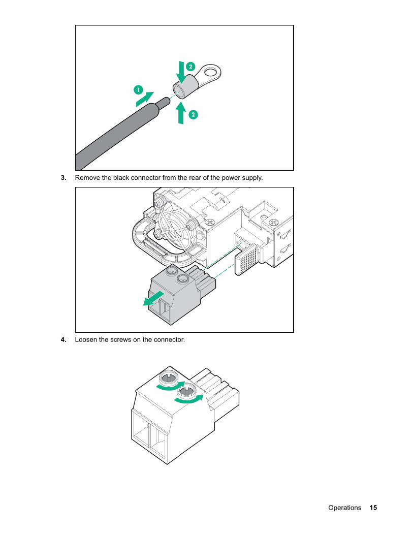
3. Remove the black connector from the rear of the power supply.
4. Loosen the screws on the connector.
Operations 15
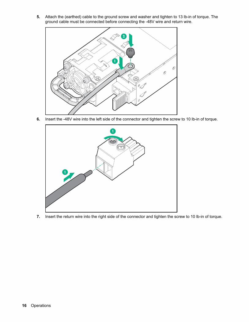
5. Attach the (earthed) cable to the ground screw and washer and tighten to 13 lb-in of torque. Theground cable must be connected before connecting the -48V wire and return wire.
6. Insert the -48V wire into the left side of the connector and tighten the screw to 10 lb-in of torque.
7. Insert the return wire into the right side of the connector and tighten the screw to 10 lb-in of torque.
16 Operations
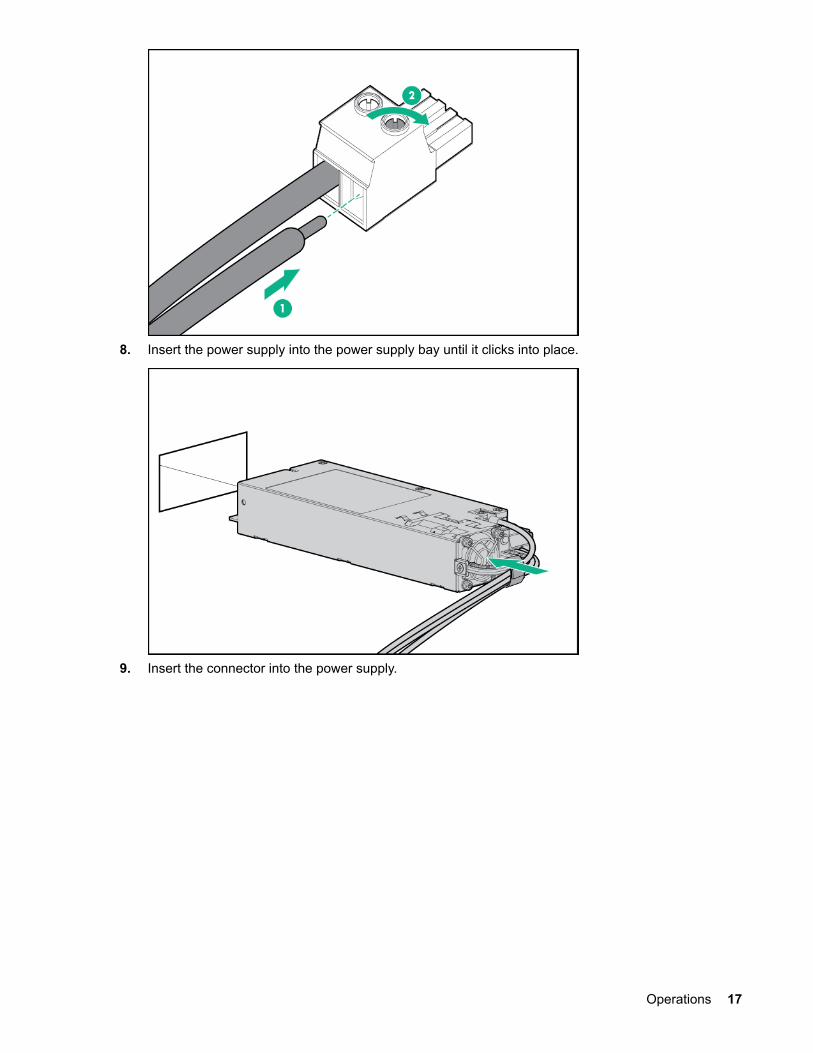
8. Insert the power supply into the power supply bay until it clicks into place.
9. Insert the connector into the power supply.
Operations 17

10. Attach the cables to the power supply handle with the hook-and-loop strap.
11. Route the power cord. Use best practices when routing power cords and other cables. A cablemanagement arm is available to help with routing. To obtain a cable management arm, contact aHewlett Packard Enterprise authorized reseller.
12. Make sure the -48V DC power source is off or the PDU breaker is in the off position, and thenconnect the power cord to the -48V DC power source or PDU.
13. Turn on the -48V power source or switch the PDU breaker to the on position to supply -48V to thepower supply.
14. Be sure that the green power supply LED is on.
Install a power supply blankProcedure
1. Align the power supply blank to the unused power supply bay on the system, and insert until it locks inplace.
18 Install a power supply blank

Power down the systemAbout this task
Before powering down the system for any upgrade or maintenance procedures, back up critical systemdata and programs.
Before performing chassis maintenance, shut down all cartridges installed in the system.
Procedure
• Use one of the following methods to power down the system:
Press and release the Power On/Standby button of the cartridges installed in the system.
This method initiates a controlled shutdown of applications and the OS before the system entersstandby mode.
Press and hold the Power On/Standby button of the cartridges installed in the system for more than4 seconds to force the system to power down.
This method forces the system to power down without properly exiting applications and the OS. Ifan application stops responding, you can use this method to force a shutdown.
Verify the system is in standby mode and the system power LED is off.
Power up the systemAbout this task
If the system is connected to a power source, it powers up automatically by default. Generally, it has to bepowered up only after a manual shutdown. However, using iLO, cartridges can be individually configuredto not power up automatically.
Procedure
• Use one of the following methods to power up the system:
Press the Power On/Standby button of the cartridge installed in the system. Remotely power up the system through iLO.
Mount the systemThe following kits are available to mount your system:
Power down the system 19

• Rack-mounting kit• Wall-mounting kit
The wall-mounting kit is non HPE and allows up to two Edgeline EL4000 systems to be installed on awall. For more details, contact RackSolutions® at http://www.racksolutions and request P/N101-5302.
Remove the access panelDepending on the configuration of your system, perform one of the following procedures:
• Removing the PCIe access panel on page 20• Removing the PXIe access panel on page 20
Removing the PCIe access panel
Procedure
1. Using a Torx screwdriver, turn the T-15 locking Torx screw a quarter turn to unlock the latch.2. Press the latch button and open the latch.3. Remove the access panel.
Removing the PXIe access panel
Procedure
1. Press the latch button and open the latch.2. Slide the panel to the rear of the chassis.3. Lift and remove the access panel.
20 Remove the access panel

2
1
Remove the fixed top coverDepending on the configuration of your system, perform one or more of the following procedures:
• Removing the fixed top cover of the PCIe system on page 21• Removing the fixed front top cover of the PXIe system on page 21• Removing the fixed rear top cover of the PXIe system on page 22
Removing the fixed top cover of the PCIe system
Procedure
1. Using a Torx screwdriver, remove the nine T-10 Torx screws securing the fixed top cover to thesystem.
Removing the fixed front top cover of the PXIe system
Procedure
1. Using a Torx screwdriver, remove the 10 T-10 Torx screws securing the fixed front top cover to thesystem.
Remove the fixed top cover 21

1
2
1
1
1
1
1
1
1
1
Removing the fixed rear top cover of the PXIe system
Procedure
1. Remove the PXIe access panel (Removing the PXIe access panel on page 20).2. Using a Torx screwdriver, remove the 14 T-10 Torx screws securing the fixed rear top cover to the
system.
1 1
1
2
1
Install the fansProcedure
1. Align the fan with the fan slots of the system.2. Squeeze the tabs on either side of the fan, and then slide it into the bay until it clicks in place.
22 Removing the fixed rear top cover of the PXIe system
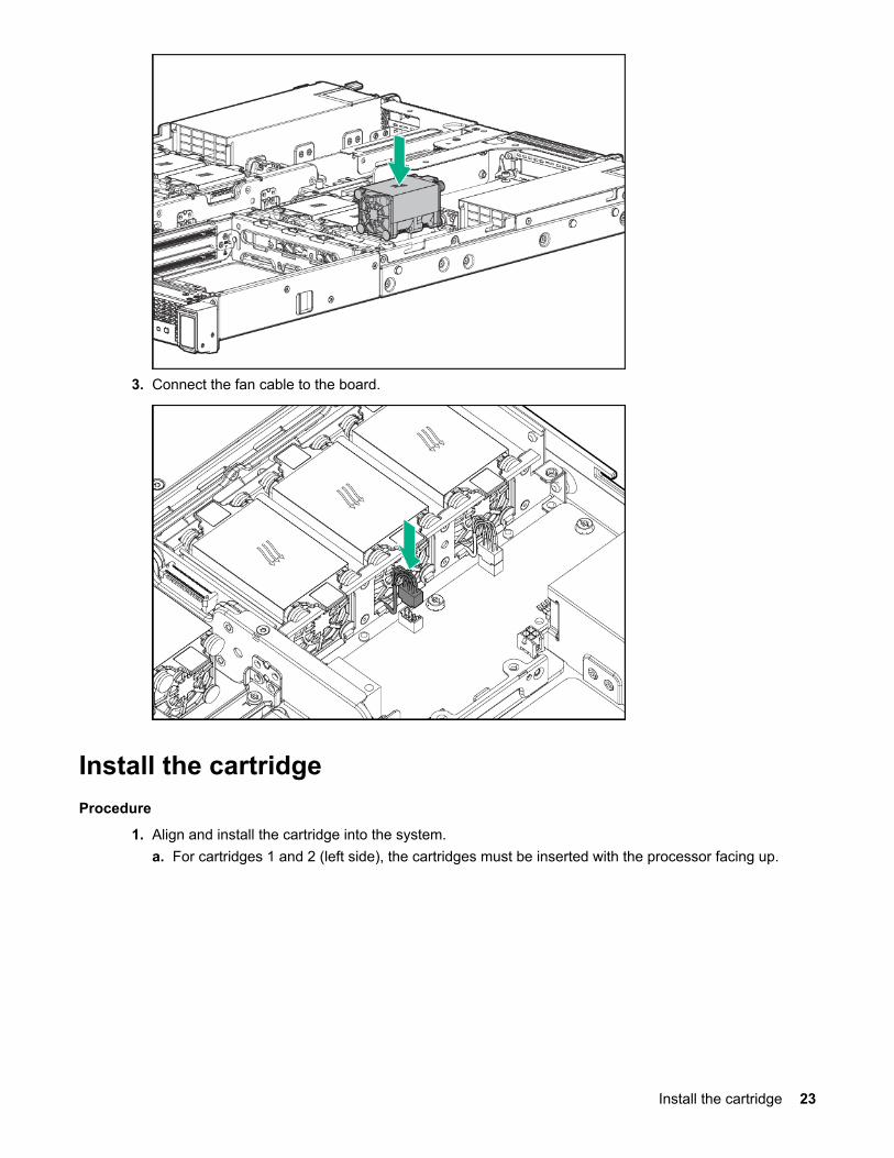
3. Connect the fan cable to the board.
Install the cartridgeProcedure
1. Align and install the cartridge into the system.a. For cartridges 1 and 2 (left side), the cartridges must be inserted with the processor facing up.
Install the cartridge 23

b. For cartridges 3 and 4 (right side)*, the cartridges must be inserted with the processor facing down.*Cartridges 3 and 4 will appear upside down from image.
24 Operations

SetupOptional services
Hewlett Packard Enterprise offers the HPE Foundation Care Next Business Day Exchange Service forthis product.
HPE Foundation Care Next Business Day Exchange Service provides a replacement product or partdelivered free of freight charges to your location the next business day after a call is opened and providessupport 24 hours per day, Monday through Sunday.
Hardware exchange offers a reliable and fast parts exchange service for eligible Hewlett PackardEnterprise products. Specifically targeted at products that can easily be shipped and on which you caneasily restore data from backup files, HPE Foundation Care Next Business Day Exchange is a cost-efficient and convenient alternative to onsite support.
Replacement products or parts are new or equivalent to new in performance.
In addition, HPE Foundation Care Next Business Day Exchange provides electronic access to relatedproduct and support information, enabling any member of your IT staff to locate commercially availableessential information.
For more information on HPE Foundation Care Next Business Day Exchange Service, see the HewlettPackard Enterprise website.
Optimum environmentWhen installing the system, select a location that meets the environmental standards.
• Space and airflow requirements on page 25• Temperature requirements on page 25• Power requirements on page 25
Space and airflow requirementsTo allow for servicing and adequate airflow, leave a minimum clearance of 20 cm (7.9 in.) around thesystem.
Temperature requirementsTo ensure continued safe and reliable equipment operation, install or position the system in a well-ventilated, climate-controlled environment.
Configuration Temperature
Chassis with cartridges installed, but no PCIecards/PXIe modules installed
Operating temperature of up to 55°C (131°F)
Power requirementsInstallation of this equipment must comply with local and regional electrical regulations governing theinstallation of information technology equipment by licensed electricians. This equipment is designed tooperate in installations covered by NFPA 70, 1999 Edition (National Electric Code) and NFPA-75, 1992(code for Protection of Electronic Computer/Data Processing Equipment). For electrical power ratings onoptions, see the product rating label or the user documentation supplied with that option.
More InformationPower supply specifications on page 47
Setup 25

Installing hardware optionsInstall any hardware options before initializing the system. For options installation information, see theoption documentation. For system-specific information, see "Hardware options installation."
Registering the productTo experience quicker service and more efficient support, register the product at the Hewlett PackardEnterprise Product Registration website.
26 Installing hardware options
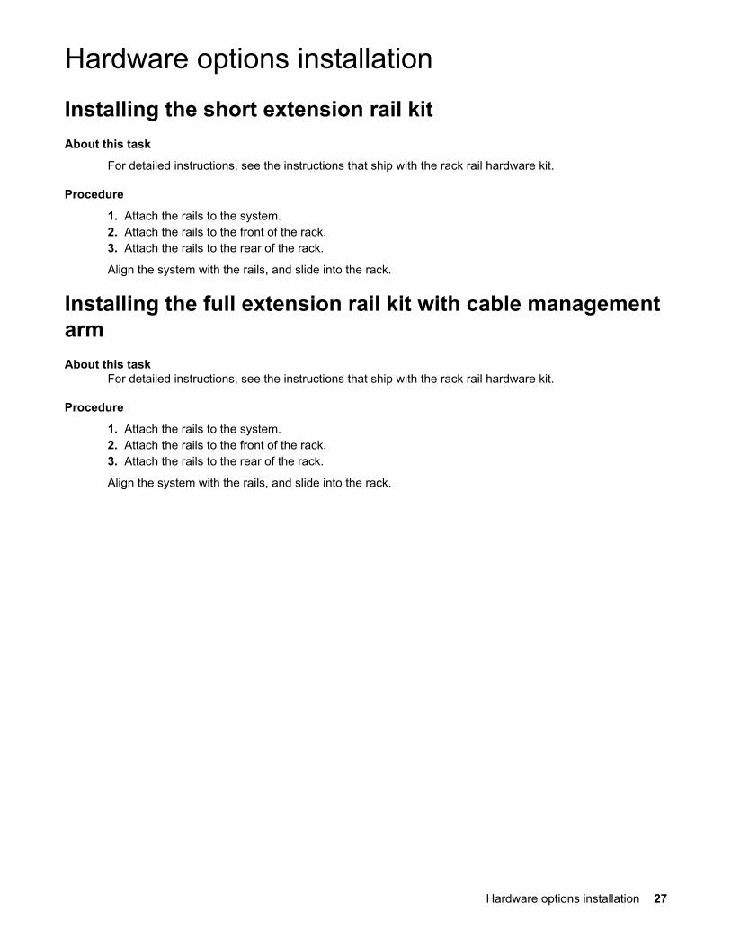
Hardware options installationInstalling the short extension rail kitAbout this task
For detailed instructions, see the instructions that ship with the rack rail hardware kit.
Procedure
1. Attach the rails to the system.2. Attach the rails to the front of the rack.3. Attach the rails to the rear of the rack.
Align the system with the rails, and slide into the rack.
Installing the full extension rail kit with cable managementarmAbout this task
For detailed instructions, see the instructions that ship with the rack rail hardware kit.
Procedure
1. Attach the rails to the system.2. Attach the rails to the front of the rack.3. Attach the rails to the rear of the rack.
Align the system with the rails, and slide into the rack.
Hardware options installation 27
ConfigurationNetworking in the chassisHPE EL4000 4x10G 2xQSFP+ PThru System networking
This configuration has two external 40GbE QSFP+ ports, labelled A and B. The NIC A of each of the fourcartridges is connected to the external port A. The NIC B of each cartridge is connected to the externalport B through a single 10G lane within the 40GbE port. The connection is a pass-through one, as thecartridge 10G NIC port is routed directly to the external port. If required, VLAN segmentation can beconfigured at the external switch, based on the ports to which the cartridges are connected.
To connect to an external switch, you can use one of the following methods:
• Using a 40G to 4x10G breakout copper or optical transceiver solution.
Each of the 10G strands of the breakout cable is a 10GbE connection to a cartridge in the chassis. Onthe HPE 40G to 4x10G DAC cable, the 10G breakout cable labeled A is connected to Cartridge 1. The10G breakout cable marked B is connected to Cartridge 2, and so on. Each of these cables can beconnected to a 10GbE SFP+ port on an external switch.
• Using a 40G to 40G copper or optical transceiver.
This 40G connection is actually four 10GbE connections carried within a single cable. At the externalswitch, the port to which this cable connects must be configured in 4x10GbE mode, rather than thenative 40GbE mode. Any per-cartridge port configuration in the external switch is applied to thecomponent 10G port within the 40G port.
HPE EL4000 10G 2xSFP+ Switch System networking
This configuration has two external 10GbE SFP+ ports, labelled A and B. The NIC A of each of the fourcartridges is internally switched within the system to the external 10GbE SFP+ port labelled A. Unicastpackets to a cartridge are sent only to that cartridge, while multicast or broadcast packets are sent to allcartridges.
For VLAN segmentation, you can use one of the following methods:
• If all the NIC As are in the same VLAN, that VLAN can be configured at the port of the external switchto which the system port A is connected. Similarly, all of the NIC Bs may be configured in anotherVLAN if necessary.
• If each cartridge must be in a different VLAN, then VLAN tagging must be configured at the cartridge,typically at the operating system level. The port of the external switch to which the EL4000 networkport is attached must be configured as a trunk port. Appropriate configuration of the tagged VLANused by the system must be done at the external switch. VLAN 1 is always treated as the untaggeddefault VLAN.
HPE EL4000 10G 2SFP+ Switch PXIe System networking (data capture and control)
This configuration has two external 10GbE SFP+ ports, labelled A and B. The NIC A of each of the fourcartridges is internally switched to the external 10GbE SFP+ port labelled A. Unicast packets to acartridge are sent only to that cartridge, while multicast or broadcast packets are sent to all cartridges.
For VLAN segmentation, you can use one of the following methods:
• If all the NIC As are in the same VLAN, that VLAN can be configured at the port of the external switchto which the system port A is connected. All of the NIC Bs can be configured to be in another VLAN.
• If each cartridge must be in a different VLAN, then VLAN tagging must be configured at the cartridge,typically at the operating system level. The port of the external switch to which the EL4000 networkport is attached must be configured as a trunk port. Appropriate configuration of the tagged VLANused by the system must be done at the external switch. VLAN 1 is always treated as the untagged
28 Configuration

default VLAN. VLAN 2 and VLAN 3 are used internally by the embedded switch within the system, andcannot be configured as tagged VLANs on the cartridges.
Accessing the System Utilities menuAbout this task
To complete these steps, you need the HPE USB-to-serial cable (HPE part number 871947-B21).
Table 1: Settings for connecting USB cable to serial port
Specifications Value
Baud rate 115200
Data bits 8
Parity None
Stop bit 1 (8 N1)
Procedure
1. Power down the cartridge.2. Connect the USB-to-serial cable to the system. The USB end is connected to a system USB port.3. Attach the serial end of the cable to a serial port using a null modem cable. The other serial port may
be another USB-to-serial adapter on a different machine.4. Power on the cartridge. The serial console output screen displays.
5. Press the ESC + 9 keys. The System Utilities menu displays.
Accessing the System Utilities menu 29
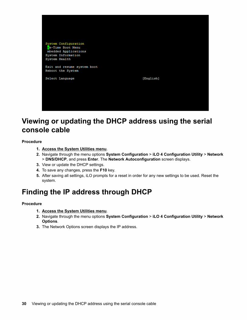
Viewing or updating the DHCP address using the serialconsole cableProcedure
1. Access the System Utilities menu.2. Navigate through the menu options System Configuration > iLO 4 Configuration Utility > Network
> DNS/DHCP, and press Enter. The Network Autoconfiguration screen displays.3. View or update the DHCP settings.4. To save any changes, press the F10 key.5. After saving all settings, iLO prompts for a reset in order for any new settings to be used. Reset the
system.
Finding the IP address through DHCPProcedure
1. Access the System Utilities menu.2. Navigate through the menu options System Configuration > iLO 4 Configuration Utility > Network
Options.3. The Network Options screen displays the IP address.
30 Viewing or updating the DHCP address using the serial console cable

Setting the static IP address using the serial console cableProcedure
1. Access the System Utilities menu.2. Navigate through the menu options System Configuration > iLO 4 Configuration Utility > Network
Options. The Network Options screen displays.3. Change DHCP Enable to OFF.4. Configure the IP Address, Subnet Mask, and Gateway Address as required. The following image is
an example of a completed Network Options screen.
Setting the static IP address using the serial console cable 31

5. Once completed, press ESC to back out of the menus. Save the settings when prompted.6. After saving all settings, iLO prompts for a reset in order for the new settings to be used. Reset the
system.
32 Configuration

Software and configuration utilitiesProduct QuickSpecs
For more information about product features, specifications, options, configurations, and compatibility, seethe product QuickSpecs on the Hewlett Packard Enterprise website.
Supported operating systems and drivers matrixTo validate the minimum supported Operating System for a system platform, go to the Hewlett PackardEnterprise website:
http://www.hpe.com/info/ossupport
To download the latest device drivers, go to the Hewlett Packard Enterprise Support Center website:
http://www.hpe.com/support/hpesc
HPE iLOiLO is a remote server management processor embedded on the system boards of HPE ProLiant andSynergy servers. iLO enables the monitoring and controlling of servers from remote locations. HPE iLOmanagement is a powerful tool that provides multiple ways to configure, update, monitor, and repairservers remotely. iLO (Standard) comes preconfigured on HPE servers without an additional cost orlicense.
Features that enhance server administrator productivity are licensed. For more information, see the iLOdocumentation on the Hewlett Packard Enterprise website.
Active Health SystemThe Active Health System monitors and records changes in the server hardware and systemconfiguration.
The Active Health System provides:
• Continuous health monitoring of over 1600 system parameters• Logging of all configuration changes• Consolidated health and service alerts with precise time stamps• Agentless monitoring that does not affect application performance
The Agentless Management Service is available in the SPP, which can be downloaded from the HewlettPackard Enterprise website. The Active Health System log can be downloaded manually from iLO 4 orIntelligent Provisioning and sent to Hewlett Packard Enterprise.
For more information, see the following documents:
• iLO User Guide on the Hewlett Packard Enterprise website• Intelligent Provisioning User Guide on the Hewlett Packard Enterprise website
Active Health System data collectionThe Active Health System does not collect information about your operations, finances, customers,employees, or partners.
Examples of data that is collected:
• Server model and serial number• Processor model and speed
Software and configuration utilities 33

• Storage capacity and speed• Memory capacity and speed• Firmware/BIOS and driver versions and settings
The Active Health System does not parse or change operating system data from third-party error eventlog activities (for example, content created or passed through the operating system).
Active Health System logThe data collected by the Active Health System is stored in the Active Health System Log. The data islogged securely, isolated from the operating system, and separate from customer data.
When the Active Health System Log is full, new data overwrites the oldest data in the log.
It takes less than 5 minutes to download the Active Health System Log and send it to a Hewlett PackardEnterprise support professional to help you resolve an issue.
When you download and send Active Health System data to Hewlett Packard Enterprise, you agree tohave Hewlett Packard Enterprise use the data for analysis, technical resolution, and qualityimprovements. The data that is collected is managed according to the privacy statement, available on the Hewlett Packard Enterprise website.
iLO RESTful API supportHPE iLO 4 firmware version 2.00 and later includes the iLO RESTful API. The iLO RESTful API is amanagement interface that server management tools can use to perform configuration, inventory, andmonitoring of the ProLiant server via iLO. The iLO RESTful API uses basic HTTPS operations (GET, PUT,POST, DELETE, and PATCH) to submit or return JSON-formatted data with iLO web server.
HPE iLO 4 2.30 and later is Redfish 1.0-conformant while remaining backward compatible with theexisting iLO RESTful API.
HPE iLO 4 supports the iLO RESTful API with ProLiant Gen8 and later servers. For more informationabout the iLO RESTful API, see the Hewlett Packard Enterprise website.
Integrated Management LogThe IML records hundreds of events and stores them in an easy-to-view form. The IML timestamps eachevent with one-minute granularity.
You can view recorded events in the IML in several ways, including the following:
• From within HPE SIM• From within the UEFI System Utilities• From within the Embedded UEFI shell• From within operating system-specific IML viewers:
For Windows: IML Viewer For Linux: IML Viewer Application
• From within the iLO web interface• From within Insight Diagnostics
HPE Insight Cluster Management UtilityThe Insight CMU is an efficient and robust hyperscale cluster lifecycle management framework and suiteof tools for large Linux clusters. A simple graphical interface enables an at-a-glance view of the entirecluster across multiple metrics, provides frictionless scalable remote management and analysis, andallows rapid software provisioning to all system nodes. Insight CMU makes cluster management moreuser friendly, efficient, and error-free than if it were being managed by scripts, or on a node-by-nodebasis. Insight CMU is highly flexible and customizable, offers both GUI and CLI interfaces, and is used to
34 Active Health System log

deploy a range of software environments, from simple compute farms to highly customized, application-specific configurations.
For more information on Insight CMU features and links to technical documentation, QuickSpecs, and aproduct demo, see the Hewlett Packard Enterprise website.
To download the product, go to the Hewlett Packard Enterprise Software Depot. Click InsightManagement, then click Insight Cluster Management.
HPE Edgeline Component PackThe HPE Edgeline Component Pack is a comprehensive firmware solution tested on the Edgeline Systemand delivered as a compressed file. The compressed file includes all the component files needed toupdate an Edgeline System. Users deploy the firmware updates contained in the HPE EdgelineComponent Pack using the included Smart Update Manager, or by updating using the firmware updatecapability of the iLO 4 on each server cartridge. Download the latest pack from the Hewlett PackardEnterprise website.
HP Smart Update ManagerHP SUM is an application included with the HPE Edgeline Component Pack that provides a web-basedGUI for installing and updating firmware on many Hewlett Packard Enterprise products, including theEdgeline System. HP SUM has an integrated discovery engine that finds the installed hardware andcurrent versions of firmware in use on nodes you identify. The application installs updates in the correctorder and ensures that all dependencies are met before deploying an update, and prevents an installationif there are version-based dependencies that it cannot resolve.
The version of HP SUM included with each HPE Edgeline Component Pack release is designed to be thebest solution for installing Edgeline System firmware updates. Always use the included version of HPSUM for Edgeline System updates. For more information, see the HPE Edgeline Component PackUpdate Guide in the Hewlett Packard Enterprise Information Library.
UEFI System UtilitiesThe UEFI System Utilities is embedded in the system ROM. The UEFI System Utilities enable you toperform a wide range of configuration activities, including:
• Configuring system devices and installed options• Enabling and disabling system features• Displaying system information• Selecting the primary boot controller• Configuring memory options• Selecting a language• Launching other preboot environments such as the Embedded UEFI Shell and Intelligent Provisioning
For more information, see the UEFI System Utilities user guide for your product on the Hewlett PackardEnterprise website.
To access mobile-ready online help for the UEFI System Utilities and UEFI Shell, scan the QR code at thebottom of the screen. For on-screen help, press the F1 key.
Using UEFI System UtilitiesTo use the System Utilities, use the following keys.
HPE Edgeline Component Pack 35

Action Key
Access System Utilities F9 during serverPOST
Navigate menus Up and Downarrows
Select items Enter
Save selections F10
Access Help for a highlighted configurationoption1
F1
1 Scan the QR code on the screen to access online help for the UEFISystem Utilities and UEFI Shell.
Default configuration settings are applied to the server at one of the following times:
• Upon the first system power-up• After defaults have been restored
Default configuration settings are sufficient for typical server operations; however, you can modifyconfiguration settings as needed. The system prompts you for access to the UEFI System Utilities eachtime the system is powered up.
Flexible boot controlThis feature enables you to do the following:
• Add Boot Options:
Browse all FAT16 and FAT32 file systems. To add a new UEFI boot option, select an X64 UEFI application with an .EFI extension. For
example, adding an OS boot loader or other UEFI application as a new UEFI boot option.
The new boot option is appended to the boot-order list. When you select a file, you are prompted toenter the boot option description. This description, and any optional data to be passed to an .EFIapplication, is then displayed in the boot menu.
• Boot to System Utilities
After pre-POST, the boot options screen appears. During this time, you can access the UEFI SystemUtilities by pressing the F9 key.
• Choose between supported modes:
Legacy BIOS Boot Mode UEFI Boot Mode
IMPORTANT:If the default boot mode settings are different than the user-defined settings, the system mightnot boot the OS installation if the defaults are restored. To avoid this issue, use the UserDefined Defaults feature in UEFI System Utilities to override the factory default settings.
For more information, see the UEFI System Utilities user guide for your product on the Hewlett PackardEnterprise Information Library.
Restoring and customizing configuration settingsYou can reset all configuration settings to the factory default settings, or you can restore and use thesystem default configuration settings.
36 Flexible boot control
You can also configure default settings as necessary, and then save the configuration as the customdefault configuration. When the system loads the default settings, it uses the custom default settingsinstead of the factory defaults.
Secure Boot configurationSecure Boot is integrated in the UEFI specification on which the Hewlett Packard Enterpriseimplementation of UEFI is based. Secure Boot is implemented in the BIOS and does not require specialhardware. Secure Boot ensures that each component launched during the boot process is digitallysigned. Secure Boot also ensures that the signature is validated against a set of trusted certificatesembedded in the UEFI BIOS. Secure Boot validates the software identity of the following components inthe boot process:
• UEFI drivers loaded from PCIe cards• UEFI drivers loaded from mass storage devices• Preboot UEFI shell applications• OS UEFI boot loaders
When enabled, only firmware components and operating systems with boot loaders that have anappropriate digital signature can execute during the boot process. Only operating systems that supportSecure Boot and have an EFI boot loader signed with one of the authorized keys can boot. For moreinformation about supported operating systems, see the UEFI System Utilities and Shell release notes foryour system on the Hewlett Packard Enterprise website.
A physically present user can customize the certificates embedded in the UEFI BIOS by adding orremoving their own certificates.
When Secure Boot is enabled, the System Maintenance Switch does not restore all manufacturingdefaults when set to the ON position. For security reasons, the following are not restored to defaults whenthe System Maintenance Switch is in the ON position:
• Secure Boot is not disabled and remains enabled.• The Boot Mode remains in UEFI Boot Mode even if the default boot mode is Legacy Boot Mode.• The Secure Boot Database is not restored to its default state.• iSCSI Software Initiator configuration settings are not restored to defaults.
Embedded UEFI shellThe system BIOS in all ProLiant Gen9 servers includes an Embedded UEFI Shell in the ROM. The UEFIShell environment provides an API, a command-line prompt, and a set of CLIs that allow scripting, filemanipulation, and system information. These features enhance the capabilities of the UEFI SystemUtilities.
For more information, see the following documents:
• UEFI Shell User Guide for HPE ProLiant Gen9 Servers on the Hewlett Packard Enterprise website• UEFI Shell Specification on the UEFI website
Embedded Diagnostics optionThe system BIOS in all ProLiant Gen9 servers includes an Embedded Diagnostics option in the ROM.The Embedded Diagnostics option can run comprehensive diagnostics of the server hardware, includingprocessors, memory, drives, and other server components.
For more information on the Embedded Diagnostics option, see the UEFI System Utilities user guide foryour system on the Hewlett Packard Enterprise website.
Secure Boot configuration 37

iLO RESTful API support for UEFIThe ProLiant Gen9 servers include support for a UEFI-compliant System BIOS, along with UEFI SystemUtilities and Embedded UEFI Shell preboot environments. ProLiant Gen9 servers also support configuringthe UEFI BIOS settings using the iLO RESTful API, a management interface that server managementtools can use to perform configuration, inventory, and monitoring of a ProLiant server. The iLO RESTfulAPI uses basic HTTPS operations (GET, PUT, POST, DELETE, and PATCH) to submit or return JSON-formatted data with iLO web server.
For more information about the iLO RESTful API and the RESTful Interface Tool, see the HewlettPackard Enterprise website.
Re-entering the server serial number and product ID
About this task
After you replace the system board, you must re-enter the system serial number and the product ID:
Procedure
1. During the system startup sequence, press the F9 key to access UEFI System Utilities.2. Select System Configuration > BIOS/Platform Configuration (RBSU) > Advanced Options >
Advanced System ROM Options > Serial Number, and then press the Enter key.3. Enter the serial number and press the Enter key.
The following message appears:
The serial number should only be modified by qualified service personnel.This value should always match the serial number located on the chassis.
4. To clear the warning, press the Enter key.5. Enter the serial number and press the Enter key.6. Select Product ID.
The following warning appears:
Warning: The Product ID should ONLY be modified by qualified servicepersonnel. This value should always match the Product ID located on thechassis.
7. Enter the product ID and press the Enter key.8. To confirm exiting System Utilities, press the F10 key.
The system automatically reboots.
38 iLO RESTful API support for UEFI

TroubleshootingHPE Edgeline Troubleshooting Guide
The HPE Edgeline System Troubleshooting Guide provides procedures for resolving common problemsand comprehensive courses of action for fault isolation and identification, issue resolution, and softwaremaintenance on the Edgeline System. The document is available in the Hewlett Packard EnterpriseInformation Library.
Troubleshooting 39

BatteryBattery specifications
Feature Specification
Type Maintenance-free, sealed, CR2032 lithium manganese dioxide button battery
Voltage 3.0 V
Replace the system batteryProcedure
1. Locate the battery on the system board:
• System board components (PCIe) on page 8• System board components (PXIe) on page 12
2. Slightly push the metal tab, and then use the small flat-nose pliers to remove the system battery fromits socket.
3. Slightly push the metal tab, then install the system battery in the socket.
40 Battery

For more information about battery replacement or proper disposal, contact an authorized reseller or anauthorized service provider.
Battery 41

Warranty and regulatory informationWarranty information
HPE ProLiant and x86 Servers and Options
HPE Enterprise Servers
HPE Storage Products
HPE Networking Products
Regulatory informationSafety and regulatory compliance
For important safety, environmental, and regulatory information, see Safety and Compliance Informationfor Server, Storage, Power, Networking, and Rack Products, available at the Hewlett Packard Enterprisewebsite (http://www.hpe.com/support/Safety-Compliance-EnterpriseProducts).
Belarus Kazakhstan Russia marking
Manufacturer and Local Representative Information
Manufacturer information:
• Hewlett Packard Enterprise Company, 3000 Hanover Street, Palo Alto, CA 94304 U.S.
Local representative information Russian:
• Russia:
• Belarus:
• Kazakhstan:
Local representative information Kazakh:
• Russia:
• Belarus:
42 Warranty and regulatory information

• Kazakhstan:
Manufacturing date:
The manufacturing date is defined by the serial number.
CCSYWWZZZZ (serial number format for this product)
Valid date formats include:
• YWW, where Y indicates the year counting from within each new decade, with 2000 as the startingpoint; for example, 238: 2 for 2002 and 38 for the week of September 9. In addition, 2010 is indicatedby 0, 2011 by 1, 2012 by 2, 2013 by 3, and so forth.
• YYWW, where YY indicates the year, using a base year of 2000; for example, 0238: 02 for 2002 and38 for the week of September 9.
Turkey RoHS material content declaration
Ukraine RoHS material content declaration
Turkey RoHS material content declaration 43

Electrostatic dischargePreventing electrostatic dischargeAbout this task
To prevent damaging the system, be aware of the precautions you must follow when setting up thesystem or handling parts. A discharge of static electricity from a finger or other conductor may damagesystem boards or other static-sensitive devices. This type of damage may reduce the life expectancy ofthe device.
Procedure
• Avoid hand contact by transporting and storing products in static-safe containers.• Keep electrostatic-sensitive parts in their containers until they arrive at static-free workstations.• Place parts on a grounded surface before removing them from their containers.• Avoid touching pins, leads, or circuitry.• Always be properly grounded when touching a static-sensitive component or assembly.
Grounding methods to prevent electrostatic dischargeSeveral methods are used for grounding. Use one or more of the following methods when handling orinstalling electrostatic-sensitive parts:
• Use a wrist strap connected by a ground cord to a grounded workstation or computer chassis. Wriststraps are flexible straps with a minimum of 1 megohm ±10 percent resistance in the ground cords. Toprovide proper ground, wear the strap snug against the skin.
• Use heel straps, toe straps, or boot straps at standing workstations. Wear the straps on both feetwhen standing on conductive floors or dissipating floor mats.
• Use conductive field service tools.• Use a portable field service kit with a folding static-dissipating work mat.
If you do not have any of the suggested equipment for proper grounding, have an authorized resellerinstall the part.
For more information on static electricity or assistance with product installation, contact an authorizedreseller.
44 Electrostatic discharge
SpecificationsProduct QuickSpecs
For more information about product features, specifications, options, configurations, and compatibility, seethe product QuickSpecs on the Hewlett Packard Enterprise website.
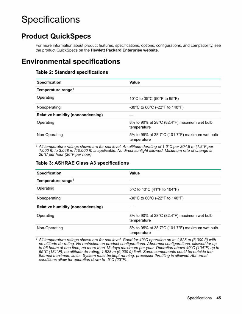
Environmental specificationsTable 2: Standard specifications
Specification Value
Temperature range1 —
Operating 10°C to 35°C (50°F to 95°F)
Nonoperating -30°C to 60°C (-22°F to 140°F)
Relative humidity (noncondensing) —
Operating 8% to 90% at 28°C (82.4°F) maximum wet bulbtemperature
Non-Operating 5% to 95% at 38.7°C (101.7°F) maximum wet bulbtemperature
1 All temperature ratings shown are for sea level. An altitude derating of 1.0°C per 304.8 m (1.8°F per1,000 ft) to 3,048 m (10,000 ft) is applicable. No direct sunlight allowed. Maximum rate of change is20°C per hour (36°F per hour).
Table 3: ASHRAE Class A3 specifications
Specification Value
Temperature range1 —
Operating 5°C to 40°C (41°F to 104°F)
Nonoperating -30°C to 60°C (-22°F to 140°F)
Relative humidity (noncondensing) —
Operating 8% to 90% at 28°C (82.4°F) maximum wet bulbtemperature
Non-Operating 5% to 95% at 38.7°C (101.7°F) maximum wet bulbtemperature
1 All temperature ratings shown are for sea level. Good for 40°C operation up to 1,828 m (6,000 ft) withno altitude de-rating. No restriction on product configurations. Abnormal configurations, allowed for upto 96 hours at one time, no more than 15 days maximum per year. Operation above 40°C (104°F) up to55°C (131°F), no altitude de-rating, 1,828 m (6,000 ft) limit. Some components could be outside thethermal maximum limits. System must be kept running, processor throttling is allowed. Abnormalconditions allow for operation down to -5°C (23°F).
Specifications 45

Table 4: ASHRAE Class A4 specifications
Specification Value
Temperature range1 —
Operating 5°C to 45°C (41°F to 113°F)
Nonoperating -30°C to 60°C (-22°F to 140°F)
Relative humidity (noncondensing) —
Operating 8% to 90% at 28°C (82.4°F) maximum wet bulbtemperature
Non-Operating 5% to 95% at 38.7°C (101.7°F) maximum wet bulbtemperature
1 All temperature ratings shown are for sea level. An altitude derating of 1.0°C per 125 m (1.8°F per 410ft) to 900 m (2,953 ft) is applicable. No direct sunlight allowed. Maximum rate of change is 20°C perhour (36°F per hour). No restrictions on product configurations except for rotating hard drives. PCI cardsmust be rated for continuous operation with 60°C cooling air. Not rated for operation over 3,030 m(10,000 ft).
Table 5: Extended Edgeline specifications
Specification Value
Temperature range1 —
Operating 0°C to 55°C (32°F to 131°F)
Nonoperating -30°C to 60°C (-22°F to 140°F)
Relative humidity (noncondensing) —
Operating 8% to 90% at 28°C (82.4°F) maximum wet bulbtemperature
Non-Operating 5% to 95% at 38.7°C (101.7°F) maximum wet bulbtemperature
1 All temperature ratings shown are for sea level. An altitude derating of 1.0°C per 304.8 m (1.8°F per1,000 ft) to 3,048 m (10,000 ft) is applicable. No direct sunlight allowed. Maximum rate of change is20°C per hour (36°F per hour).
Environmental specifications-system components support matrixEnvironmentalspecification
Support status
Basesystem
Fans SATA M.2drives
NVME M.2drives
PCIecards
PXIemodules
Standard OperatingSupport
Yes Yes (withredundancy)
Yes Yes Yes Yes (up to38 W)1
Extended Ambient40°C OperatingSupport (ASHRAEClass A3 Compliant)
Yes Yes (withredundancy)
Yes Yes Yes Yes (up to38 W)1
Table Continued
46 Environmental specifications-system components support matrix

Environmentalspecification
Support status
Basesystem
Fans SATA M.2drives
NVME M.2drives
PCIecards
PXIemodules
Extended Ambient45°C OperatingSupport (ASHRAEClass A4 Compliant)
Yes Yes (withredundancy)2
Yes Yes3 Yes No
Extended Edgeline0°C to 55°COperating Support
Yes4 Yes (withredundancy)2
Yes No Yes5 No
1 Maximum altitude is 2,000 m (800 mbar) (at 25 °C ambient temperature)2 Upon fan failure, the servers in the system might have reduced performance3 M.2 drive might exceed its spec by 2°C to 3°C and have slight throttling.4 Near 55°C inlet ambient temperature, when the CPU is stressed at 100%, the HPE m510 -16c server
might have reduced performance.5 The PCI card must have inlet spec rated at 65°C or higher, and an air speed of 375 ft/min.
Mechanical specificationsSpecification Value
Length 615 mm (24.21 in)
Width 435 mm (17.13 in)
Depth 43 mm (1.69 in)
Weight 14 kg (30.86 lb)
Power supply specificationsDepending on installed options, the system is configured with one of the following power supplies:
• HPE 800W Flex Slot Platinum Hot Plug Power Supply on page 47• HPE 800W Flex -48VDC Hot Plug Power Supply on page 48
For detailed power supply specifications, see the QuickSpecs on the Hewlett Packard Enterprise website(http://www.hpe.com/info/proliant/powersupply).
HPE 800W Flex Slot Platinum Hot Plug Power SupplySpecification Value
Input voltage range(V rms)
100 to 240
Frequency range(Nominal) (Hz)
50 to 60
Nominal inputvoltage (V rms)
100 120 127 200 208 220 230 240
Maximum ratedoutput wattagerating (Watts)
800 800 800 800 800 800 800 800
Table Continued
Mechanical specifications 47

Nominal inputcurrent (A rms)
9.1 7.5 7.0 4.4 4.2 4.0 3.8 3.7
Maximum ratedinput wattagerating (Watts)
906 891 878 871 870 869 868 868
Maximum rated VA(Volt-Amp)
915 900 887 880 879 877 876 877
Efficiency (%) 88.3 89.8 91.1 91.9 92.0 92.1 92.2 92.1
Power factor 0.99 0.99 0.99 0.99 0.99 0.99 0.99 0.99
Leakage current(mA)
0.32 0.38 0.40 0.63 0.65 0.69 0.72 0.75
Maximum inrushcurrent (A peak)
30 30 30 30 30 30 30 30
Maximum inrushcurrent duration(ms)
10 10 10 10 10 10 10 10
Maximum BritishThermal Unit rating(BTU-Hr)
3090 3040 2997 2972 2968 2963 2960 2963
HPE 800W Flex -48VDC Hot Plug Power SupplySpecification Value
Input voltage range (V DC) -40 to -72
Frequency range (Nominal) (Hz) DC
Nominal input voltage (V DC) -40 -48 -72
Maximum rated output wattagerating (Watts)
800 800 800
Nominal input current (A DC) 22.0 18.1 11.9
Maximum rated input wattagerating (Watts)
882 871 858
Maximum rated VA (Volt-Amp) 882 871 858
Efficiency (%) 90.7 91.9 93.2
Power factor 1.0 1.0 1.0
Leakage current (mA) 0.0 0.0 0.0
Maximum inrush current (A peak) 30 30 30
Maximum inrush current duration(ms)
10 10 10
Maximum British Thermal Unitrating (BTU-Hr)
3008 2971 2929
48 HPE 800W Flex -48VDC Hot Plug Power Supply

PXI/PXIe specificationsNOTE: Specifications are subject to change without notice.
Electrical load regulation specificationsVoltage (V) Load regulation (%)
+3.3 <5
+12 <5
Chassis cooling specificationsSpecification Value
Module cooling system Forced air circulation (positive pressurization)through seven fans with High/Auto speed selector.
Airflow From front to rear
Pollution specifications
Specifications Value
Pollution degree 2
For indoor use only in a climate-controlled environment.
Shock and vibration specificationsSpecification Value
Operational shock 30 g peak, half-sine, 11 ms pulse
Random vibration 5 Hz to 500 Hz, 0.3 g rms
Acoustic emission specifications
Acoustic noise
Acoustic noise specifications for the following base configurations are available.
Table 6: Base configuration 1 (m510)
Component Quantity Specification
Cartridge 4 m510
DIMMs/cartridge 4 Any
SATA M.2/cartridge 1 64 GB
NVME M.2/cartridge 0 NA
PXI 4 PXI 6341
PSU 2 800 W AC
PXI/PXIe specifications 49
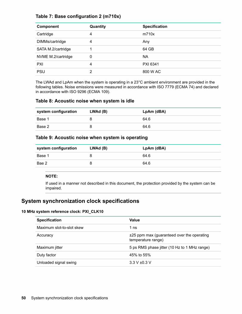
Table 7: Base configuration 2 (m710x)
Component Quantity Specification
Cartridge 4 m710x
DIMMs/cartridge 4 Any
SATA M.2/cartridge 1 64 GB
NVME M.2/cartridge 0 NA
PXI 4 PXI 6341
PSU 2 800 W AC
The LWAd and LpAm when the system is operating in a 23°C ambient environment are provided in thefollowing tables. Noise emissions were measured in accordance with ISO 7779 (ECMA 74) and declaredin accordance with ISO 9296 (ECMA 109).
Table 8: Acoustic noise when system is idle
system configuration LWAd (B) LpAm (dBA)
Base 1 8 64.6
Base 2 8 64.6
Table 9: Acoustic noise when system is operating
system configuration LWAd (B) LpAm (dBA)
Base 1 8 64.6
Bae 2 8 64.6
NOTE:
If used in a manner not described in this document, the protection provided by the system can beimpaired.
System synchronization clock specifications
10 MHz system reference clock: PXI_CLK10
Specification Value
Maximum slot-to-slot skew 1 ns
Accuracy ±25 ppm max (guaranteed over the operatingtemperature range)
Maximum jitter 5 ps RMS phase jitter (10 Hz to 1 MHz range)
Duty factor 45% to 55%
Unloaded signal swing 3.3 V ±0.3 V
50 System synchronization clock specifications
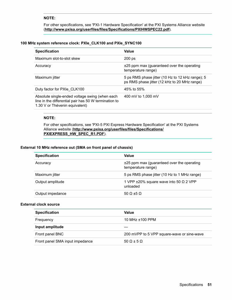
NOTE:
For other specifications, see 'PXI-1 Hardware Specification' at the PXI Systems Alliance website(http://www.pxisa.org/userfiles/files/Specifications/PXIHWSPEC22.pdf).
100 MHz system reference clock: PXIe_CLK100 and PXIe_SYNC100
Specification Value
Maximum slot-to-slot skew 200 ps
Accuracy ±25 ppm max (guaranteed over the operatingtemperature range)
Maximum jitter 5 ps RMS phase jitter (10 Hz to 12 kHz range); 5ps RMS phase jitter (12 kHz to 20 MHz range)
Duty factor for PXIe_CLK100 45% to 55%
Absolute single-ended voltage swing (when eachline in the differential pair has 50 W termination to1.30 V or Thévenin equivalent)
400 mV to 1,000 mV
NOTE:
For other specifications, see 'PXI-5 PXI Express Hardware Specification' at the PXI SystemsAlliance website (http://www.pxisa.org/userfiles/files/Specifications/PXIEXPRESS_HW_SPEC_R1.PDF).
External 10 MHz reference out (SMA on front panel of chassis)
Specification Value
Accuracy ±25 ppm max (guaranteed over the operatingtemperature range)
Maximum jitter 5 ps RMS phase jitter (10 Hz to 1 MHz range)
Output amplitude 1 VPP ±20% square wave into 50 Ω 2 VPPunloaded
Output impedance 50 Ω ±5 Ω
External clock source
Specification Value
Frequency 10 MHz ±100 PPM
Input amplitude —
Front panel BNC 200 mVPP to 5 VPP square-wave or sine-wave
Front panel SMA input impedance 50 Ω ± 5 Ω
Specifications 51

WebsitesGeneral websites
Hewlett Packard Enterprise Information Librarywww.hpe.com/info/EIL
Single Point of Connectivity Knowledge (SPOCK) Storage compatibility matrixwww.hpe.com/storage/spock
Storage white papers and analyst reportswww.hpe.com/storage/whitepapers
For additional websites, see Support and other resources.
52 Websites
Support and other resources
Accessing Hewlett Packard Enterprise Support• For live assistance, go to the Contact Hewlett Packard Enterprise Worldwide website.• To access documentation and support services, go to the Hewlett Packard Enterprise Support
Center website.
Information to collect• Technical support registration number (if applicable)• Product name, model or version, and serial number• Operating system name and version• Firmware version• Error messages• Product-specific reports and logs• Add-on products or components• Third-party products or components
Accessing updates• Some software products provide a mechanism for accessing software updates through the product
interface. Review your product documentation to identify the recommended software update method.• To download product updates:
Hewlett Packard Enterprise Support Centerwww.hpe.com/support/hpesc
Hewlett Packard Enterprise Support Center: Software downloadswww.hpe.com/support/downloads
Software Depotwww.hpe.com/support/softwaredepot
• To subscribe to eNewsletters and alerts:
www.hpe.com/support/e-updates• To view and update your entitlements, and to link your contracts and warranties with your profile, go to
the Hewlett Packard Enterprise Support Center More Information on Access to Support Materialspage:
www.hpe.com/support/AccessToSupportMaterials
IMPORTANT:
Access to some updates might require product entitlement when accessed through the HewlettPackard Enterprise Support Center. You must have an HPE Passport set up with relevantentitlements.
Customer self repairHewlett Packard Enterprise customer self repair (CSR) programs allow you to repair your product. If aCSR part needs to be replaced, it will be shipped directly to you so that you can install it at yourconvenience. Some parts do not qualify for CSR. Your Hewlett Packard Enterprise authorized serviceprovider will determine whether a repair can be accomplished by CSR.
Support and other resources 53

For more information about CSR, contact your local service provider or go to the CSR website:
http://www.hpe.com/support/selfrepair
Remote supportRemote support is available with supported devices as part of your warranty or contractual supportagreement. It provides intelligent event diagnosis, and automatic, secure submission of hardware eventnotifications to Hewlett Packard Enterprise, which will initiate a fast and accurate resolution based on yourproduct's service level. Hewlett Packard Enterprise strongly recommends that you register your device forremote support.
If your product includes additional remote support details, use search to locate that information.
Remote support and Proactive Care information
HPE Get Connected
HPE Proactive Care services
HPE Proactive Care service: Supported products list
HPE Proactive Care advanced service: Supported products list
Proactive Care customer information
Proactive Care central
Proactive Care service activation
54 Remote support
Acronyms and abbreviationsCM
chassis management
EMC
Electromagnetic compatibility
iLO
Integrated Lights-Out
LpAm
declared average bystander position A-Weighted sound pressure levels
LTE
long-term evolution
LWAd
declared A-Weighted sound power levels
PCI
peripheral component interconnect
PCIe
Peripheral Component Interconnect Express
PXE
preboot execution environment
PXI
PCI eXtensions for instrumentation
PXIe
PCI eXtensions for instrumentation express
QSFP+
enhanced quad small form-factor pluggable
SFP+
enhanced small form-factor pluggable
UEFI
Unified Extensible Firmware Interface
UID
unit identification
WiFi
wireless fidelity
WLAN
wireless local area network
WWAN
Acronyms and abbreviations 55

wireless wide area network
56 Acronyms and abbreviations

Documentation feedbackHewlett Packard Enterprise is committed to providing documentation that meets your needs. To help usimprove the documentation, send any errors, suggestions, or comments to Documentation Feedback([email protected]). When submitting your feedback, include the document title, part number,edition, and publication date located on the front cover of the document. For online help content, includethe product name, product version, help edition, and publication date located on the legal notices page.
Documentation feedback 57