hpe basic power distribution unit installation guideh20628. · hpe g2 series basic power...
TRANSCRIPT
HPE G2 Series Basic Power Distribution Unit User Guide
Abstract
This document is for the person who installs and maintains HPE PDU products. Hewlett Packard Enterprise assumes you are qualified in the installation of electrical equipment and trained in recognizing hazards in products with hazardous energy levels.
Part Number: 872619-001 November 2016 Edition: 1

© Copyright 2016 Hewlett Packard Enterprise Development LP
The information contained herein is subject to change without notice. The only warranties for Hewlett Packard Enterprise products and services are set forth in the express warranty statements accompanying such products and services. Nothing herein should be construed as constituting an additional warranty. Hewlett Packard Enterprise shall not be liable for technical or editorial errors or omissions contained herein.

3
Contents
Before you begin .................................................................................................................................... 5
Overview .................................................................................................................................................................. 5
Important safety information ..................................................................................................................................... 5
Required tools .......................................................................................................................................................... 6
PDU form factors ................................................................................................................................... 7
Rack Mounting Options ............................................................................................................................................ 7
0U (Vertical) mounting configurations ...................................................................................................................... 8
1U PDU mounting configurations (True 0U) ............................................................................................................. 8
Load Segment & Phase Distinction .......................................................................................................................... 9
Recommended PDU installation methods .......................................................................................... 10
Vertical PDU installation ......................................................................................................................................... 10
Single PDU installation ................................................................................................................................ 10
Two or four PDU installation ........................................................................................................................ 10
High density PDU installation ...................................................................................................................... 11
Installation method for mid and full height vertical units .............................................................................. 11
Hardware installation ................................................................................................................................... 12
PDU shipping retention for rack transportation............................................................................................ 13
Installing a Vertical PDU in an HPE 14U Advance rack, a Standard series rack or an older 10K series rack..................................................................................................................................................................... 14
1U PDU installation ................................................................................................................................................ 15
Hardware installation ................................................................................................................................... 16
2U PDU installation ................................................................................................................................................ 17
Hardware installation ................................................................................................................................... 18
0U/1U PDU installation ........................................................................................................................................... 19
Hardware installation ................................................................................................................................... 19
Extension bar installation ....................................................................................................................................... 22
Power cord retention ............................................................................................................................ 24
Integrated cord retention ........................................................................................................................................ 24
HPE locking power cord ......................................................................................................................................... 25
Retention for PDUs with NEMA 5-20R outlets ....................................................................................................... 26
Grounding ............................................................................................................................................ 27
Connecting the ground bonding cable .................................................................................................................... 27
Checking the circuit breakers ............................................................................................................... 27
Spares ................................................................................................................................................. 27
Ordering spares ...................................................................................................................................................... 27

4
PDU spare parts list ............................................................................................................................................... 28
Hardware options ................................................................................................................................................... 29
Warranty and regulatory information .................................................................................................... 29
Warranty information .............................................................................................................................................. 29
Regulatory information ........................................................................................................................................... 29
Safety and regulatory compliance ............................................................................................................... 29
Belarus Kazakhstan Russia marking ........................................................................................................... 29
Turkey RoHS material content declaration .................................................................................................. 30
Ukraine RoHS material content declaration ................................................................................................ 30
Support and other resources................................................................................................................ 30
Accessing Hewlett Packard Enterprise Support ..................................................................................................... 30
Websites ................................................................................................................................................................. 31
Customer Self Repair ............................................................................................................................................. 31
Acronyms and abbreviations ................................................................................................................ 32
Documentation feedback ..................................................................................................................... 32

5
Before you begin
Overview This document provides installation and configuration instructions for qualified personnel for installing a Hewlett Packard Enterprise Basic Power Distribution Unit (PDU) into a datacenter rack.
Important safety information See the complete regulatory compliance notices in Safety and Compliance Information for Server, Storage, Power, Networking, and Rack Products on the Hewlett Packard Enterprise website (http://www.hpe.com/support/Safety-Compliance-EnterpriseProducts). In addition, follow the safety precautions that are specific to this device.
This PDU is intended only for Information Technology Equipment (ITE) loads with linear/Power Factor Corrected (PFC) input current. If non-linear loads are connected, the nameplate current rating of the PDU must be reduced by a factor of 0.8.
WARNING: A risk of personal injury from electric shock and hazardous energy levels exists. The installation of options and routine maintenance and service of this product must be performed by individuals who are knowledgeable on the procedures, precautions, and hazards associated with AC power products.
Follow these safety precautions when connecting multiple hardware components to power sources.
WARNING: To reduce the risk of fire, electric shock and damage to the equipment: • Connect only to a circuit providing branch circuit overcurrent protection of appropriate
current rating. • Connect the input power cord to a grounded (earthed) electrical outlet that is located near
the equipment and is easily accessible. • Be sure all circuit breakers are in the off position before connecting input power. • Be sure that the load products connected to the HPE PDU are adjusted for, or otherwise
capable of, operation from the same line voltage supplying the PDU. Failure to verify the voltage can lead to severe equipment damage.
• Do not overload the PDU. The total input current rating of all equipment connected to each output cannot exceed the total output rating marked on the PDU.
• Use only the hardware provided to install the PDU.

6
WARNING: To reduce the risk of personal injury from high-leakage current, verify earth connection before connecting the power supply. The summation of input power for multiple pieces of information technology equipment through the use of power products can result in high-leakage currents. If the total system leakage current for a system of components exceeds 3.5 mA: • The use of a detachable input power cord is prohibited. • The input power cord must be securely attached, and it should be connected to the AC
mains by hardwiring or through the use of a non-residential, industrial-style plug that maintains positive earth connection.
• If the total system leakage current through the ground conductor exceeds 5% of the input current per line under normal operating conditions, the system loads should be divided among multiple power connections.
Required tools The following tools are required for installation:
• Phillips screwdriver
• Torx screwdriver

7
PDU form factors
Details of the form factors that are covered within this document
Form Factor Details 0U (Vertical) These PDUs come in Half, Mid, & Full Height versions and install vertically in the 0U space in the back of the
rack. There are also Half and Full Height high-density models that install vertically in the 0U space in the back of the rack. The high-density model mounts on its side with outlets facing the back of the rack.
1U These PDUs can be installed in a U position in the rack or in the true 0U space on the side of the rack between the RETMA rails.
2U These PDUs can be installed in a U position in the rack.
Rack Mounting Options
HPE PN Form Factor 0U (Vertical)
0U (Between RETMA Rail) U position in rack
P9Q31A 0U/1U P9Q32A 0U - Half-height P9Q33A 1U P9Q34A 0U - Half-height P9Q35A 2U P9Q36A 0U/1U P9Q37A 0U/1U P9Q38A 0U - Half-height P9Q39A 1U P9Q40A 1U P9Q41A 0U - Half-height P9Q42A 0U - Mid-height P9Q43A 1U P9Q44A 1U P9Q45A 0U - Half-height P9Q46A 0U - Mid-height P9Q47A 1U P9Q48A 0U - Mid-height P9Q49A 0U - Mid-height P9Q50A 0U - Mid-height P9Q51A 1U P9Q52A 1U P9Q53A 0U - Mid-height P9Q54A 0U - Half-height P9Q55A 0U - Mid-height P9Q56A 0U - Full-height P9Q57A 0U/1U P9Q58A 0U - Mid-height P9Q59A 1U P9Q60A 1U P9Q61A 0U - Half-height * P9Q62A 0U - Full-height * P9Q63A 1U P9Q64A 0U - Half-height * P9Q65A 0U - Full-height *
* HPE high density model mounts on its side with outlets facing the back of the rack.

8
0U (Vertical) mounting configurations Mounting configuration for 0U (vertical) PDUs in an HPE 1075mm deep rack (max PDUs per side of rack)
HPE PN Form Factor 14U 22U 36U 42U 47U 48U P9Q31A 0U/1U 1** 2 2 6 6 6 P9Q32A 0U - Half-height 2 2 4 4 4 P9Q34A 0U - Half-height 2 2 4 4 4 P9Q36A 0U/1U 1** 2 2 6 6 6 P9Q37A 0U/1U 1** 2 2 6 6 6 P9Q38A 0U - Half-height 2 2 4 4 4 P9Q41A 0U - Half-height 2 2 4 4 4 P9Q42A 0U - Mid-height 2 2 2 2 P9Q45A 0U - Half-height 2 2 4 4 4 P9Q46A 0U - Mid-height 2 2 2 2 P9Q48A 0U - Mid-height 2 2 2 2 P9Q49A 0U - Mid-height 2 2 2 2 P9Q50A 0U - Mid-height 2 2 2 2 P9Q53A 0U - Mid-height 2 2 2 2 P9Q54A 0U - Half-height 2 2 4 4 4 P9Q55A 0U - Mid-height 2 2 2 2 P9Q56A 0U - Full-height 2 2 2 P9Q57A 0U/1U 1** 2 2 6 6 6 P9Q58A 0U - Mid-height 2 2 2 2 P9Q61A 0U - Half-height * 1 1 2 2 2 P9Q62A 0U - Full-height * 1 1 1 P9Q64A 0U - Half-height * 1 1 2 2 2 P9Q65A 0U - Full-height * 1 1 1
* HPE high density model mounts on its side with outlets facing the back of the rack ** H6L32A mounting bracket is required to install this PDU vertically in the back of the rack.
1U PDU mounting configurations (True 0U) Mounting configuration for a 1U PDU in an HPE 1075mm deep rack between the racks RETMA rails (max PDUs per side of rack)
HPE PN Form Factor 14U 22U 36U 42U 47U 48U P9Q31A 0U/1U 2 4 4 8 8 8 P9Q33A 1U 1 2 2 4 4 4 P9Q36A 0U/1U 2 4 4 8 8 8 P9Q37A 0U/1U 2 4 4 8 8 8 P9Q39A 1U 1 2 2 4 4 4 P9Q40A 1U 1 2 2 4 4 4 P9Q43A 1U 1 2 2 4 4 4 P9Q44A 1U 1 2 2 4 4 4 P9Q47A 1U 1 2 2 4 4 4 P9Q51A 1U 1 2 2 4 4 4 P9Q52A 1U 1 2 2 4 4 4 P9Q57A 0U/1U 2 4 4 8 8 8 P9Q59A 1U 1 1 2 4 4 4 P9Q60A 1U 1 2 2 4 4 4 P9Q63A 1U 1 2 2 4 4 4
9
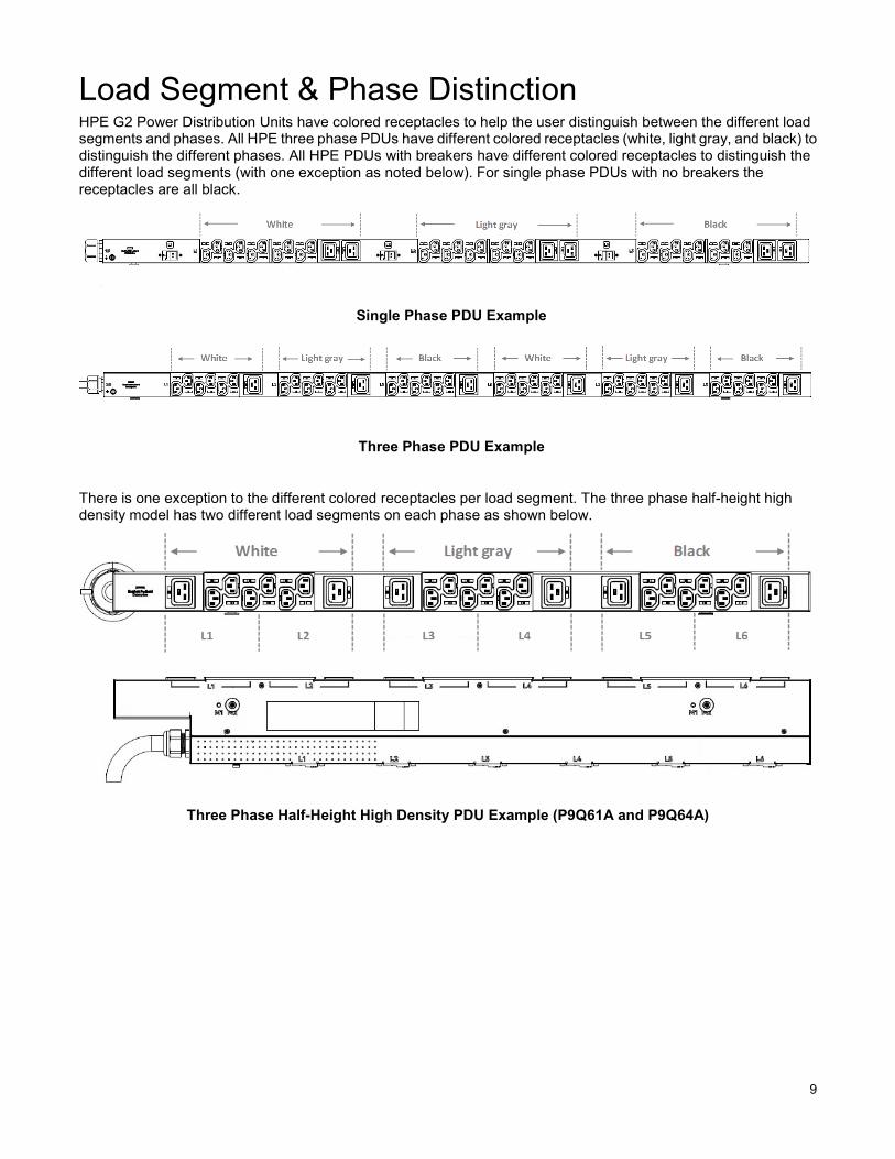
Load Segment & Phase Distinction HPE G2 Power Distribution Units have colored receptacles to help the user distinguish between the different load segments and phases. All HPE three phase PDUs have different colored receptacles (white, light gray, and black) to distinguish the different phases. All HPE PDUs with breakers have different colored receptacles to distinguish the different load segments (with one exception as noted below). For single phase PDUs with no breakers the receptacles are all black.
Single Phase PDU Example
Three Phase PDU Example
There is one exception to the different colored receptacles per load segment. The three phase half-height high density model has two different load segments on each phase as shown below.
Three Phase Half-Height High Density PDU Example (P9Q61A and P9Q64A)

10
Recommended PDU installation methods
Vertical PDU installation Vertical PDUs include the following form factors: half-height, mid-height and full-height models. Listed below are the recommended installation methods.
Single PDU installation A single vertical unit can be installed with the outlets facing the center (A), outlets facing the back of the rack (B), or outlets facing the front of the rack (C). The pictures below demonstrate these installation methods.
(A) (B) (C)
NOTE: The above installation methods are true for all vertical models except for the high density models. The high density model mounts on its side with outlets facing the rear of the rack. See section below for the recommended installation of the high density models.
Two or four PDU installation In order for two full-height (in a 42U/47U/48U rack), two mid-height (in a 36U/42U/47U/48U rack), or four half-height (in a 42U/47U/48U rack) vertical units to be mounted on one side of the rack, all units must be installed with the outlets facing in towards the center of the rack.

11
(A) (B) (C)
(A) Two full-height PDUs with outlets facing in towards the center of the rack; (B) Two mid-height PDUs with outlets facing in towards center of the rack; (C) Four half-height PDUs with outlets facing in towards center of the rack.
High density PDU installation This unique form factor comes in both full-height and half-height models and can only be installed on the sides of the PDU with the outlets facing the back of the rack. NOTE: One full-height can be installed per side whereas two half-height models can be installed per side (one on the top and the other on the bottom).
Installation method for mid and full height vertical units The PDU can also mount with the outlets facing in towards the center, back or front of the rack.

12
Hardware installation Each PDU has two different mounting hole locations on the sides and back of the PDU for the button installation (i.e., M1 or M2) to assist with mounting in a non HPE racks. When installing the mounting buttons, use both of either the M1 or M2 mounting holes as a set.
Mounting button installation - outlets facing the center of the rack 1. Align and install the mounting buttons with the screw holes on the face opposite of the receptacles.
2. Install the PDU by inserting the mounting buttons into the keyhole slots on the PDU mounting bracket.
13
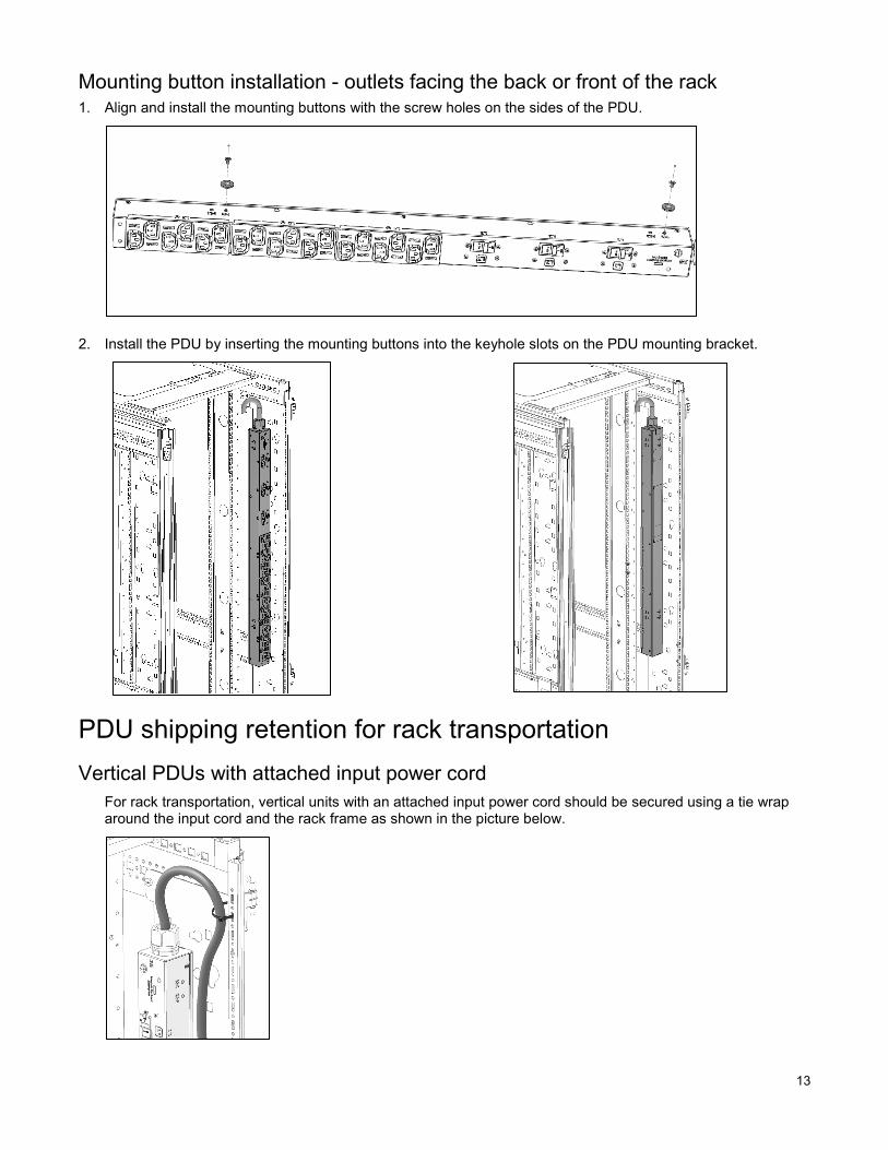
Mounting button installation - outlets facing the back or front of the rack 1. Align and install the mounting buttons with the screw holes on the sides of the PDU.
2. Install the PDU by inserting the mounting buttons into the keyhole slots on the PDU mounting bracket.
PDU shipping retention for rack transportation Vertical PDUs with attached input power cord
For rack transportation, vertical units with an attached input power cord should be secured using a tie wrap around the input cord and the rack frame as shown in the picture below.

14
Vertical PDUs with detached input power cord and half-height models For rack transportation, vertical units with a detached input power cord and all half-height models should be secured using the shipping retention locking tape.
1. Remove the adhesive backing from only one side of the shipping retention locking tape.
2. Place it directly above the unit on the rack PDU mounting bracket.
NOTE: If for any reason the PDU needs to be removed from the rack, remove the top piece of the locking tape and the unit can be lifted out of the rack.
Installing a Vertical PDU in a HPE 14U Advance rack, a Standard series rack or an older 10K series rack Installing a vertical PDU in these racks requires option kit H6L32A.

15
1. Install the brackets on the PDU using the hardware provided.
2. Install the PDU on the rack frame.
1U PDU installation This unit can be installed in any 1U location of the rack or in the true 0U space between RETMA rails with the outlets facing down.
16
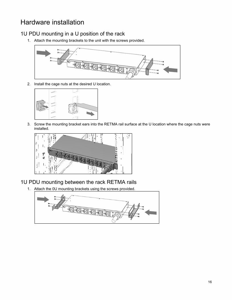
Hardware installation 1U PDU mounting in a U position of the rack
1. Attach the mounting brackets to the unit with the screws provided.
2. Install the cage nuts at the desired U location.
3. Screw the mounting bracket ears into the RETMA rail surface at the U location where the cage nuts were
installed.
1U PDU mounting between the rack RETMA rails 1. Attach the 0U mounting brackets using the screws provided.

17
2. Insert the mounting screws into the desired 0U location along the RETMA rails.
3. Rest the cutout on the end of the bracket on the screw and pivot the PDU until the holes lineup with the hole
in the bracket.
4. Insert and tighten the screws provided through the bracket into the holes in the RETMA rails of the rack.
2U PDU installation This unit can be installed in any 2U location of the rack.

18
Hardware installation 1. Mount the power cord retention bracket. The 2U PDU has 5-20R receptacles which require an additional
bracket to be mounted on the PDU if cord retention is needed.
2. Attach the mounting brackets. Each bracket requires four screws per side.
3. Install cage nuts at the desired U locations.
4. Install the PDU.

19
0U/1U PDU installation This unit can be installed in the true 0U mounting space, in a 1U location of the rack or in the true 0U space between RETMA rails.
Hardware installation 1. Attach the power cord retention bracket on models with 5-20R receptacles, if needed. The bracket mounts
to the hole marked “C” on the sides of the unit. All IEC C13 and C19 receptacles have an integrated cord retention feature and do not require a cord retention bracket.
0U/1U model 1U bracket installation 1. Install the 1U mounting brackets. Attach the mounting brackets to the unit with the screws provided.
2. Install the cage nuts at the desired U location.
3. Screw the mounting bracket ears into the RETMA rail surface at the U location where the cage nuts were installed.

20
0U/1U model 0U vertical installation 1. Align and install the mounting buttons with the screw holes marked "M”. Install the PDU into the rack by
inserting the mounting buttons into the keyhole slots on the PDU mounting bracket
a. Bracket installation: PDU facing the back of rack
b. Bracket installation: PDU facing the center of rack
c. Bracket installation: PDU facing the front of rack

21
0U/1U model true 0U mounting installation 1. Attach the 0U mounting brackets using the screws provided.
2. Screw mounting screws into the desired 0U location along the RETMA rails.
3. Rest the cutout on the end of the bracket on the screw and pivot the PDU until the holes lineup with the hole
in the bracket.
4. Insert and tighten the screws provided through the bracket into the holes in the RETMA rails of the rack.

22
Extension bar installation The extension bars can be installed with the outlets facing in towards the center, the rear, or the front of the rack.
Extension bar installation There is an extension bar model with 5-20R receptacles which requires an additional bracket to be mounted on the extension bar for cord retention. Extension bars with IEC receptacles have integrated cord retention and locking power cord capabilities.
1. Attach the 5-20R cord retention bracket.
2. Attach the mounting brackets according to the desired installations shown below.
a) Bracket installation for outlets facing in towards the center of rack.

23
b) Bracket installation for outlets facing towards the back of rack.
c) Bracket installation for outlets facing towards the front of rack.
3. Insert and tighten the screws into the rack frame.
24
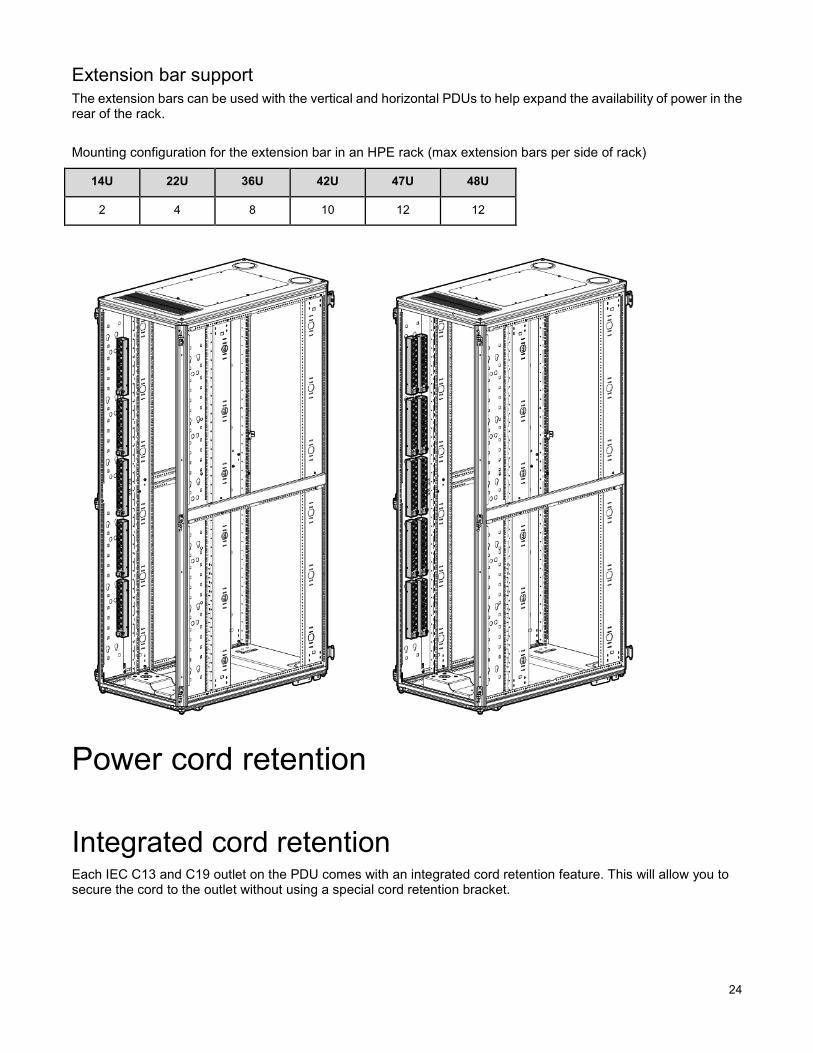
Extension bar support The extension bars can be used with the vertical and horizontal PDUs to help expand the availability of power in the rear of the rack.
Mounting configuration for the extension bar in an HPE rack (max extension bars per side of rack)
Power cord retention
Integrated cord retention Each IEC C13 and C19 outlet on the PDU comes with an integrated cord retention feature. This will allow you to secure the cord to the outlet without using a special cord retention bracket.
14U 22U 36U 42U 47U 48U
2 4 8 10 12 12
25
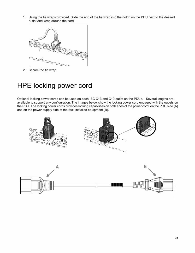
1. Using the tie wraps provided. Slide the end of the tie wrap into the notch on the PDU next to the desired outlet and wrap around the cord.
2. Secure the tie wrap.
HPE locking power cord
Optional locking power cords can be used on each IEC C13 and C19 outlet on the PDUs. Several lengths are available to support any configuration. The images below show the locking power cord engaged with the outlets on the PDU. The locking power cords provides locking capabilities on both ends of the power cord, on the PDU side (A) and on the power supply side of the rack installed equipment (B).

26
Retention for PDUs with NEMA 5-20R outlets PDUs with 5-20R outlets require the installation of a separate retention bracket in order to secure the input power cord at the outlet.
1. Using the bracket(s) and screws provided, attach the bracket to the unit by screwing the screws at the location on the unit.
Note: A tie wrap will be used for single 5-20R outlets.
2. Mount the PDU into the rack.
3. Feed the tie wrap through the hole in the retention bracket and around the input cord.

27
Grounding
Connecting the ground bonding cable There is an external ground bonding point located on the chassis of the PDU. The ground bonding screw is provided as an attachment point for conductors. Use a ground bonding cable if the rack contains any conductors for the purpose of functional grounding or bonding of ungrounded metal parts. This bonding point can also be used to bond the PDU to a known earthed reference terminal in the building. Per international regulatory requirements, the primary Safety Earth Bond connection is contained in the PDU as an integral part of the branch circuit cabling and plug.
Checking the circuit breakers
If power to a device is interrupted, check the circuit breakers and reset if necessary. Install cage nuts
Spares
Ordering spares To order a spare, visit the Hewlett Packard Enterprise website (http://www.hpe.com/info/hpparts).
To replace parts under warranty, contact a Hewlett Packard Enterprise authorized service representative.

28
PDU spare parts list
SKU Description Spare part number
P9Q31A HPE G2 Basic 1.9kVA/(12) 5-20R NA/JP PDU 868586-001
P9Q32A HPE G2 Basic 1.9kVA/(16) 5-20R NA/JP PDU 868587-001
P9Q33A HPE G2 Basic Mdlr 2.8kVA/C19 NA/JP PDU 868588-001
P9Q34A HPE G2 Basic 2.8kVA/(22) 5-20R NA/JP PDU 868589-001
P9Q35A HPE G2 Basic 2.8kVA/(16) 5-20R NA/JP PDU 868590-001
P9Q36A HPE G2 Basic Mdlr 3.6kVA/(2) C19 WW PDU 868591-001
P9Q37A HPE G2 Basic 3.6kVA/(12) C13 WW PDU 868592-001
P9Q38A HPE G2 Basic 3.6kVA/C13 C19 WW PDU 868593-001
P9Q39A HPE G2 Basic Mdlr 4.9kVA/C19 NA/JP PDU 868594-001
P9Q40A HPE G2 Basic 4.9kVA/(12) C13 NA/JP PDU 868595-001
P9Q41A HPE G2 Basic 4.9kVA/(20) C13 NA/JP PDU 868596-001
P9Q42A HPE G2 Basic 4.9kVA/C13 C19 NA/JP PDU 868597-001
P9Q43A HPE G2 Basic Modular 7.3kVA/C19 INTL PDU 868598-001
P9Q44A HPE G2 Basic 7.3kVA/(12) C13 INTL PDU 868599-001
P9Q45A HPE G2 Basic 7.3kVA/(20) C13 INTL PDU 868600-001
P9Q46A HPE G2 Basic 7.3kVA/C13 C19 INTL PDU 868601-001
P9Q47A HPE G2 Basic Mdlr 8.3kVA/C19 NA/JP PDU 868602-001
P9Q48A HPE G2 Basic 8.3kVA/C13 C19 NA/JP PDU 868603-001
P9Q49A HPE G2 Basic 9.2kVA/C13 C19 WW PDU 868604-001
P9Q50A HPE G2 Basic 11kVA/C13 C19 INTL PDU 868605-001
P9Q51A HPE G2 Basic Mdlr 14.4kVA/C19 INTL PDU 868606-001
P9Q52A HPE G2 Basic Mdlr 3Ph 8.6kVA/NA/JP PDU 868607-001
P9Q53A HPE G2 Basic 3Ph 8.6kVA/C19 NA/JP PDU 868608-001
P9Q54A HPE G2 Basic 3Ph 8.6kVA/C13 NA/JP PDU 868609-001
P9Q55A HPE G2 Basic 3Ph 8.6kVA/5-20R NA/JP PDU 868610-001
P9Q56A HPE G2 Basic 3Ph 10kVA/C13 C19 NA/JP PDU 868611-001
P9Q57A HPE G2 Basic Mdlr 3Ph 11kVA/C19 INTL PDU 868612-001
P9Q58A HPE G2 Basic 3Ph 11kVA/C13 C19 INTL PDU 868613-001
P9Q59A HPE G2 Basic Mdlr 3Ph 14.4kVA/NA/JP PDU 868614-001
P9Q60A HPE G2 Basic Mdlr 3Ph 17.3kVA/NA/JP PDU 868615-001
P9Q61A HPE G2 Basic 3Ph 17.3kVA/C13 NA/JP PDU 868616-001
P9Q62A HPE G2 Basic 3Ph 17.3kVA/C19 NA/JP PDU 868617-001
P9Q63A HPE G2 Basic Mdlr 3Ph 22kVA/C19 INTL PDU 868618-001
P9Q64A HPE G2 Basic 3Ph 22kVA/(18) C13 INTL PDU 868619-001
P9Q65A HPE G2 Basic 3Ph 22kVA/(36) C13 INTL PDU 868620-001
P9Q66A HPE G2 PDU Ext Bar Kit with C13 Outlets 868621-001
P9Q67A HPE G2 PDU Ext Bar Kit with C13 C19 868622-001
P9Q68A HPE G2 PDU Extension Kit with 5-20R 868623-001

29
Hardware options For information on the supported hardware options, see the Hewlett Packard Enterprise website (http://www.hpe.com/info/rackandpower).Warranty and regulatory information
Warranty and regulatory information
Warranty information HPE ProLiant and x86 Servers and Options (http://www.hpe.com/support/ProLiantServers-Warranties)
Regulatory information Safety and regulatory compliance
For important safety, environmental, and regulatory information, see Safety and Compliance Information for Server, Storage, Power, Networking, and Rack Products, available at the Hewlett Packard Enterprise website (http://www.hpe.com/support/Safety-Compliance-EnterpriseProducts).
Belarus Kazakhstan Russia marking
Manufacturer and Local Representative Information
Manufacturer information:
Hewlett Packard Enterprise Company, 3000 Hanover Street, Palo Alto, CA 94304 U.S.
Local representative information Russian:
• Russia:
• Belarus:
• Kazakhstan:

30
Local representative information Kazakh:
• Russia:
• Belarus:
• Kazakhstan:
Manufacturing date:
The manufacturing date is defined by the serial number.
CCSYWWZZZZ (serial number format for this product)
Valid date formats include:
• YWW, where Y indicates the year counting from within each new decade, with 2000 as the starting point; for example, 238: 2 for 2002 and 38 for the week of September 9. In addition, 2010 is indicated by 0, 2011 by 1, 2012 by 2, 2013 by 3, and so forth.
• YYWW, where YY indicates the year, using a base year of 2000; for example, 0238: 02 for 2002 and 38 for the week of September 9.
Turkey RoHS material content declaration
Ukraine RoHS material content declaration
Support and other resources
Accessing Hewlett Packard Enterprise Support • For live assistance, go to the Contact Hewlett Packard Enterprise Worldwide website
(http://www.hpe.com/assistance).
• To access documentation and support services, go to the Hewlett Packard Enterprise Support Center website (http://www.hpe.com/support/hpesc).

31
Websites • Hewlett Packard Enterprise Information Library (http://www.hpe.com/info/enterprise/docs)
• Hewlett Packard Enterprise Support Center (http://www.hpe.com/support/hpesc)
• Contact Hewlett Packard Enterprise Worldwide (http://www.hpe.com/assistance)
• Subscription Service/Support Alerts (http://www.hpe.com/support/e-updates)
• Software Depot (http://www.hpe.com/support/softwaredepot)
• Customer Self Repair (http://www.hpe.com/support/selfrepair)
Customer Self Repair Hewlett Packard Enterprise products are designed with many Customer Self Repair (CSR) parts to minimize repair time and allow for greater flexibility in performing defective parts replacement. If during the diagnosis period Hewlett Packard Enterprise (or Hewlett Packard Enterprise service providers or service partners) identifies that the repair can be accomplished by the use of a CSR part, Hewlett Packard Enterprise will ship that part directly to you for replacement. There are two categories of CSR parts:
• Mandatory—Parts for which customer self-repair is mandatory. If you request Hewlett PackardEnterprise to replace these parts, you will be charged for the travel and labor costs of this service.
• Optional—Parts for which customer self-repair is optional. These parts are also designed forcustomer self-repair. If, however, you require that Hewlett Packard Enterprise replace them for you,there may or may not be additional charges, depending on the type of warranty service designatedfor your product.
NOTE: Some Hewlett Packard Enterprise parts are not designed for customer self-repair. In order to satisfy the customer warranty, Hewlett Packard Enterprise requires that an authorized service provider replace the part. These parts are identified as "No" in the Illustrated Parts Catalog.
Based on availability and where geography permits, CSR parts will be shipped for next business day delivery. Same day or four-hour delivery may be offered at an additional charge where geography permits. If assistance is required, you can call the Hewlett Packard Enterprise Support Center and a technician will help you over the telephone. Hewlett Packard Enterprise specifies in the materials shipped with a replacement CSR part whether a defective part must be returned to Hewlett Packard Enterprise. In cases where it is required to return the defective part to Hewlett Packard Enterprise, you must ship the defective part back to Hewlett Packard Enterprise within a defined period of time, normally five (5) business days. The defective part must be returned with the associated documentation in the provided shipping material. Failure to return the defective part may result in Hewlett Packard Enterprise billing you for the replacement. With a customer self-repair, Hewlett Packard Enterprise will pay all shipping and part return costs and determine the courier/carrier to be used.
For more information about the Hewlett Packard Enterprise CSR program, contact your local service provider. For the North American program, go to the Hewlett Packard Enterprise CSR website (http://www.hpe.com/support/selfrepair).
32
AC Alternating Current
ITE Information Technology Equipment
kVA Kilo Volt Ampere
PDU Power Distribution Unit
PFC Power Factor Corrected
Documentation feedback
Hewlett Packard Enterprise is committed to providing documentation that meets your needs. To help us improve the documentation, send any errors, suggestions, or comments to Documentation Feedback (mailto:[email protected]). When submitting your feedback, include the document title, part number, edition, and publication date located on the front cover of the document. For online help content, include the product name, product version, help edition, and publication date located on the legal notices page.
Acronyms and abbreviations