hp23 series units - complete heatingcompleteheating.ca/images/pdf/lennoxhp23.pdf · hp23 series...
TRANSCRIPT
SERVICE HP23UNIT
INFORMATION
Page 1 1993 Lennox Industries Inc.
Corp. 9428–L10Replaces Corp. 9330-L4 Litho U.S.A.
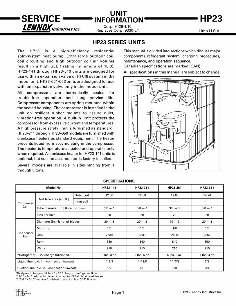
HP23 SERIES UNITS
The HP23 is a high-efficiency residentialsplit-system heat pump. Extra large outdoor coil,coil circuiting and high outdoor coil air volumeresult in a high SEER rating (minimum of 10.0).HP23-141 through HP23-510 units are designed foruse with an expansion valve or RFCIII system in theindoor unit. HP23-651/653 units are designed for usewith an expansion valve only in the indoor unit.
All compressors are hermetically sealed fortrouble-free operation and long service life.Compressor components are spring mounted withinthe sealed housing. The compressor is installed in theunit on resilient rubber mounts to assure quiet,vibration-free operation. A built-in limit protects thecompressor from excessive current and temperatures.A high pressure safety limit is furnished as standard.HP23–211 through HP23–650 models are furnished withcrankcase heaters as standard equipment. The heaterprevents liquid from accumulating in the compressor.The heater is temperature-actuated and operates onlywhen required. A crankcase heater for HP23-141 units isoptional, but suction accumulator is factory installed.
Several models are available in sizes ranging from 1through 5 tons.
This manual is divided into sections which discuss majorcomponents refrigerant system, charging procedures,maintenance, and operation sequence.Canadian specifications are marked (CAN).
All specifications in this manual are subject to change.
SPECIFICATIONS
Model No. HP23-141 HP23-211 HP23-261 HP23-311
N t f ( ft )Outer coil 12.60 12.60 12.60 14.70
CondenserNet face area (sq. ft.)
Inner coil - - - - - - - - - - - - - - - -
Coil Tube diameter (in.) & no. of rows 3/8 — 1 3/8 — 1 3/8 — 1 3/8 — 1
Fins per inch 20 20 20 20
Diameter (in.) & no. of blades 20 — 3 20 — 3 20 — 3 20 — 3
Motor hp 1/6 1/6 1/6 1/6
CondenserFan Cfm 2630 2630 2630 2665
Rpm 840 840 840 850
Watts 210 210 210 210
*Refrigerant — 22 charge furnished 5 lbs. 3 oz. 5 lbs. 6 oz. 6 lbs. 2 oz. 7 lbs. 3 oz.
Liquid line (o.d. in.) connection (sweat) **3/8 ***3/8 ***3/8 3/8
Suction line (o.d. in.) connection (sweat) 1/2 5/8 5/8 3/4
*Refrigerant charge sufficient for 20 ft. length of refrigerant lines.**3/8” x 1/4” reducer furnished to adapt to 1/4 field fabricated line set.***3 /8” x 5/16” reducer furnished to adapt unit to 5/16” line set.

Page 2
SPECIFICATIONS (contd.)
Model No. HP23-411/HP23-413 HP23-461/HP23-463 HP23-511/HP23-513 HP23-651/HP23-653
Net face area (sq ft )Outer coil 14.70 20 20.00 20.00
CondenserNet face area (sq. ft.)
Inner coil 3.9 - - - - 6.3 19Coil Tube diameter (in.) & no. of rows 3/8 — 1.3 3/8 — 1.0 3/8 — 1.3 3/8 — 2.0
Fins per inch 20 20 20 20
Diameter (in.) & no. of blades 20 — 3 20 — 4 24 — 4 24 — 4
CondenserMotor hp 1/6 1/4 1/4 1/4
CondenserFan Cfm 2600 3980 3980 3950Fan
Rpm 845 840 830 825
Watts 200 350 340 370
*Refrigerant — 22 charge furnished 7lbs. 14oz. / 7lbs. 5oz. 8 lbs. 3 oz. 9 lbs. 6 oz. 12 lbs. 13 oz.
Liquid line (o.d. in.) connection (sweat) 3/8 3/8 3/8 3/8
Suction line (o.d. in.) connection (sweat) 3/4 7/8 7/8 1-1/8*Refrigerant charge sufficient for 20 ft. length of refrigerant lines.
ELECTRICAL DATA
Model No. HP23-141 HP23-211 HP23-261 HP23-311-1 HP23-311-2 HP23-411 HP23-411–2
Line voltage data 208/230v 60hz-1ph
Rated load amps 5.0 8.1 10.9 12.2 13.7 16.3 16.2
Compressor Power factor .97 .99 .95 .97 0.99 .99 .91
Locked rotor amps 26.3 49.0 61.0 71.0 75.0 86.7 96.0
Condenser Coil Full load amps 1.1 1.1 1.1 1.1 1.1 1.1 1.1Fan Motor Locked rotor amps 1.7 1.7 1.7 1.7 1.7 1.7 1.7
Rec. max. fuse or circuit breaker size(amps) 15 15 25 25 30 35 35
*Minimum circuit ampacity 7.4 11.3 14.8 16.4 18.2 21.5 21.3*Refer to National Electrical Code manual to determine wire, fuse and disconnect size requirements.NOTE — Extremes of operating range are plus 10% and minus 5% of line voltage.
ELECTRICAL DATA
Model No. HP23-413 HP23-461-1 HP23-463-1
Line voltage data — 60hz. 208/2303ph
460v3ph 208/230v 1ph 208/230v
3ph460v3ph
Rated load amps 11.6 5.1 18.6 12.7 5.8
Compressor Power factor .88 .88 .94 .82 .82
Locked rotor amps 65.1 32.8 102.0 91.0 42.0
Condenser Coil Full load amps 1.1 0.6 1.7 1.7 1.1Fan Motor Locked rotor amps 1.7 0.9 3.1 3.1 2.2
Rec. max. fuse or circuit breaker size (amps) 25 15 40 30 15
*Minimum circuit ampacity 15.6 7.0 25.0 17.6 8.4*Refer to National Electrical Code manual to determine wire, fuse and disconnect size requirements.NOTE — Extremes of operating range are plus 10% and minus 5% of line voltage.
ELECTRICAL DATA
Model No. HP23-511 HP23-513 HP23-651 HP23-653
Line voltage data — 60 hz 208/230v 1ph 208/230v 3ph 460v 3ph 208/230v 1ph 208/230v 3ph 460v 3ph
Rated load amps 24.4 16.1 8.4 30.8 17.4 9.7
Compressor Power factor .98 .78 .78 .98 .78 .78
Locked rotor amps 135.0 137.0 68.0 147.0 150.0 73.0
Condenser Coil Full load amps 1.7 1.7 1.1 1.7 1.7 1.1Fan Motor Locked rotor amps 3.1 3.1 2.2 3.1 3.1 2.2
Rec. max. fuse or circuit breaker size (amps) 50 35 15 60 40 20
*Minimum circuit ampacity 32.2 21.9 10 40.2 23.5 13.3*Refer to National Electrical Code manual to determine wire, fuse and disconnect size requirements.NOTE — Extremes of operating range are plus 10% and minus 5% of line voltage.
Page 3
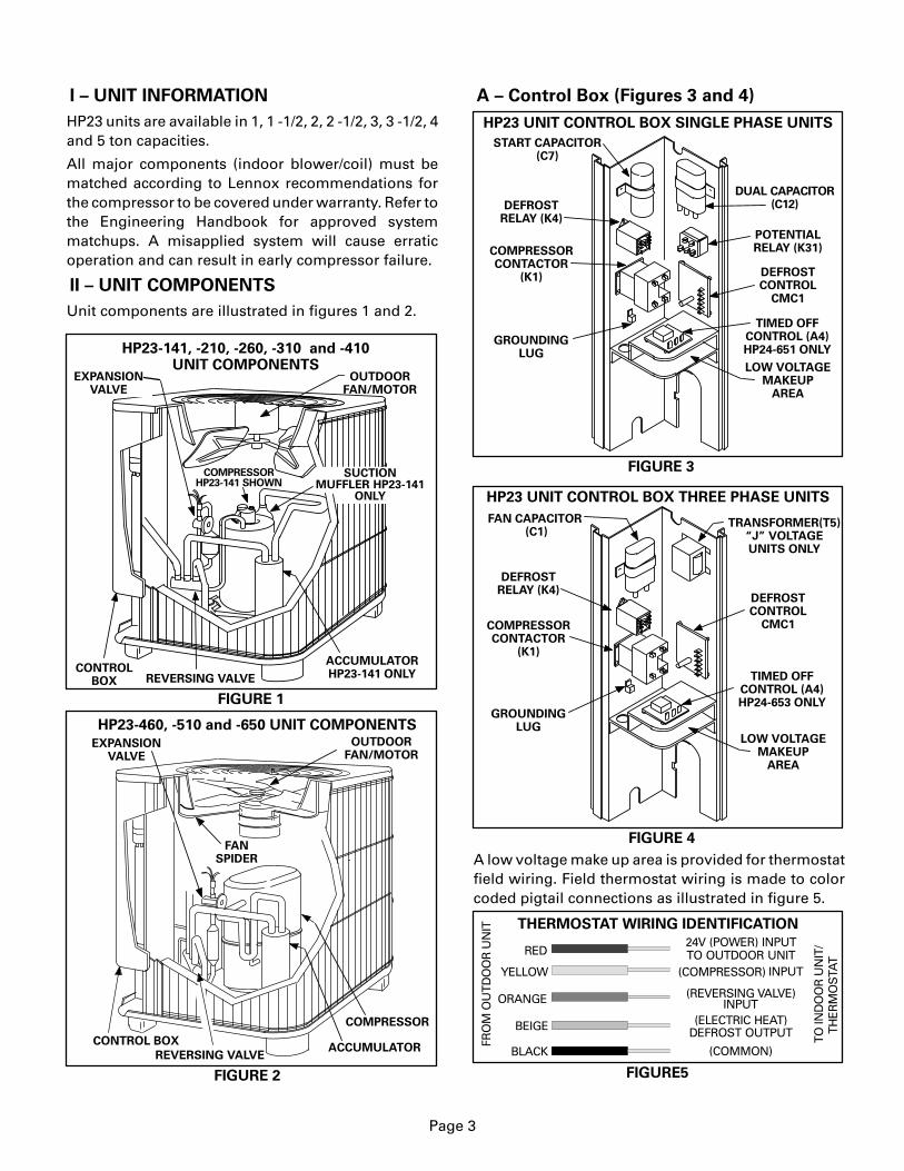
I – UNIT INFORMATION
HP23 units are available in 1, 1 -1/2, 2, 2 -1/2, 3, 3 -1/2, 4and 5 ton capacities.
All major components (indoor blower/coil) must bematched according to Lennox recommendations forthe compressor to be covered under warranty. Refer tothe Engineering Handbook for approved systemmatchups. A misapplied system will cause erraticoperation and can result in early compressor failure.
II – UNIT COMPONENTS
Unit components are illustrated in figures 1 and 2.
COMPRESSORHP23-141 SHOWN
EXPANSIONVALVE
CONTROLBOX REVERSING VALVE
SUCTIONMUFFLER HP23-141
ONLY
OUTDOORFAN/MOTOR
HP23-141, -210, -260, -310 and -410UNIT COMPONENTS
ACCUMULATORHP23-141 ONLY
FIGURE 1
HP23-460, -510 and -650 UNIT COMPONENTS
REVERSING VALVEACCUMULATOR
COMPRESSOR
OUTDOORFAN/MOTOR
CONTROL BOX
EXPANSIONVALVE
FIGURE 2
FANSPIDER
A – Control Box (Figures 3 and 4)
FIGURE 3
DUAL CAPACITOR(C12)
START CAPACITOR(C7)
POTENTIALRELAY (K31)COMPRESSOR
CONTACTOR(K1)
HP23 UNIT CONTROL BOX SINGLE PHASE UNITS
GROUNDINGLUG
DEFROSTRELAY (K4)
DEFROSTCONTROL
CMC1
LOW VOLTAGEMAKEUP
AREA
TIMED OFFCONTROL (A4)HP24-651 ONLY
FIGURE 4
FAN CAPACITOR (C1)
HP23 UNIT CONTROL BOX THREE PHASE UNITS
TRANSFORMER(T5)“J” VOLTAGEUNITS ONLY
GROUNDINGLUG
COMPRESSORCONTACTOR
(K1)
DEFROSTRELAY (K4)
DEFROSTCONTROL
CMC1
LOW VOLTAGEMAKEUP
AREA
TIMED OFFCONTROL (A4)HP24-653 ONLY
A low voltage make up area is provided for thermostatfield wiring. Field thermostat wiring is made to colorcoded pigtail connections as illustrated in figure 5.
FIGURE5
THERMOSTAT WIRING IDENTIFICATION
BLACK
BEIGE
ORANGE
YELLOW
RED
FRO
M O
UTD
OO
R U
NIT
TO IN
DO
OR
UN
IT/
THER
MO
STA
T
24V (POWER) INPUTTO OUTDOOR UNIT
(COMPRESSOR)
(REVERSING VALVE)
(ELECTRIC HEAT)
(COMMON)
INPUT
INPUT
DEFROST OUTPUT

Page 4
1 – Compressor Contactor K1
The compressor is energized by a contactor located inthe control box. See figures 3 and 4. Contactors areSPST in single phase units and 3PST in three phaseunits. K1 is energized by the indoor thermostatterminal Y (24V). HP23 units are not equipped with a linevoltage to 24V transformer. All 24 VAC controls arepowered by the indoor unit. Refer to unit wiring diagram.
DANGER
Shock Hazard
All single phase HP23 units usesingle-pole contactors. One leg ofcompressor, capacitor and outdoorfan are connected to line voltage atall times. Potential exists forelectrical shock resulting in injuryor death. Remove all power atdisconnect before servicing.
Can cause personal injury or death.
2 – Dual Capacitor C12
The compressor and fan in single phase units usepermanent split capacitor motors. The capacitor islocated inside the unit control box (see figure 3). A single“dual” capacitor (C12) is used for both the fan motor andthe compressor (see unit wiring diagram). The fan sideand the compressor side of the capacitor have differentMFD ratings. See table 1 for dual capacitor ratings.
TABLE 1
Unit MFD VAC
HP23 (C12) DUAL CAPACITOR RATING
HP23–211/261
HP23–311-1/411
HP23–461
HP23–511/651
535545
10
370
1040
60
Terminal
FANHERMFAN
HERM
FANHERMFAN
HERM
440
HP23–141 525
FANHERM
HP23–311-2535
FANHERM
HP23–411-2540
FANHERM
3 – Potential Relay K31 (Start)
All single phase units use a potential relay whichcontrols the operation of the starting circuit. Thepotential relay is located inside the unit control box (seefigure 3). The relay is normally closed when contactorK2 is de-energized. When K1 energizes, the compressorimmediately begins start-up. K31 remains closedduring compressor start-up and start capacitor C7remains in the circuit. As the compressor gains speed,K31 is energized. When K31 energizes, the contactsopen and start capacitor C7 is taken out of the circuit.
4 – Start Capacitor C7All single phase units use a start capacitor (C7). C7 islocated inside the unit control box (see figure 3). C7 iswired in parallel with the compressor side of the dualcapacitor. See table 2 for start capacitor ratings.
TABLE 2
Unit MFD VACHP23 START CAPACITOR RATING (C7)
HP23–141/211/261
HP23–411–2/461/511
88–108 250
189-227 330HP23–411 (CAN)
HP23–311-1/411 88–108 330
25088–108
HP23–651 270-324 330
HP23–311-2 145–175 330
5 – Timed Off Control A4 (–651 / –653 only)A time delay (A4) located in the control box is used onthe HP23-650-2 series. See figures 3 and 4. The timedelay is electrically connected between thermostatterminal Y and the compressor contactor. After coolingdemand has stopped, A4 begins counting for fiveminutes. During the timing period, A4 disables thecompressor contactor. Thermostat demand will haveno effect on the unit.The unit cannot operate. After thedelay, the compressor contactor can be energized.
DANGERDo not attempt to repair this control. Unsafeoperation will result. If the control has failed,replace the control.
6 – Fan Capacitor C1The fan in three-phase units uses a single phasepermanent split capacitor motor. A single capacitor C1 isused for the fan motor. C1 is located inside the unitcontrol box (see figure 4). Table 3 shows the ratings of C1.
TABLE 3
Unit MFD VAC
HP23 FAN CAPACITOR RATING (C1)
HP23–413Y,GHP23–463/513/653G
HP23-513,653J 7.5 370
5 370
HP23-463/513/653Y 10 370
7 – Transformer T5Transformer T5 is used on all “J” voltage units. T5 isused as a step-down transformer for fan B4. T5 is rated at3.4 VA with a 575 volt primary and a 460 volt secondary.8 – Defrost Relay K4The defrost relay controls defrost. The relay is a 3PDTrelay powered 24 VAC from the thermostat. K4 isenabled during both cooling and heating modes(except emergency heat). It is only powered when thedefrost control is calling for defrost. When energized,the reversing valve and indoor auxiliary heat areenergized. Simultaneously, the outdoor fan isde-energized. K4 latches in for the duration of thedefrost period. Refer to unit wiring diagram andoperation sequence in the back of this manual.

Page 5
9 – Defrost Control CMC1
The CMC1 defrost control (figure 6) is a solid state controlmanufactured by Hamilton Standard. The controlprovides automatic switching from normal heatingoperation to defrost mode and back. The controlprovides 14 minute defrost periods at 30, 60 or 90 minutefield changeable intervals. The control monitorsthermostat demand and “holds” the timer in placebetween thermostat demand. A set of diagnostic pins arealso provided for troubleshooting the unit.
The control contains a solid state timer which switchesan external defrost relay through 1/4” male spadesmounted on the control’s circuit board. When thedefrost thermostat closes (call for defrost), the defrosttimer initiates a 30, 60 or 90 minute (depending on howthe control is preset) timing sequence. If the defrostthermostat remains closed when the timing sequenceends, the defrost relay is energized and defrost begins.
SOLID STATE DEFROST CONTROL CMC1
TimingJumper
Timing PinsTroubleshooting Pins
Control Terminals
30 60 90
FIGURE 6
A defrost period can last up to 14 minutes and can beterminated two ways. If the defrost thermostat doesnot open within 14 minutes after defrost begins, thetimer will de–energize the defrost relay and the unitwill resume normal operation. If the defrostthermostat opens during the 14 minute defrost period,the defrost relay is de–energized and the unit resumesnormal operation. Refer to figure 7.
ÉÉÉÉÉÉÉÉÉÉÉÉÉÉÉÉÉÉÉÉÉÉÉÉÉÉÉÉÉÉÉÉÉÉ
ÉÉÉÉÉÉÉÉÉÉÉÉÉÉÉÉÉÉÉÉÉÉÉÉÉÉÉÉÉÉÉÉÉÉÉÉÉÉÉÉÉÉÉ
ÉÉÉÉÉÉÉÉÉÉÉÉÉ
ÉÉÉÉÉÉÉÉÉÉÉÉÉÉÉÉÉÉÉÉÉÉÉÉÉÉÉÉÉÉÉÉÉÉÉÉÉÉÉÉÉÉÉÉÉ ÉÉÉ
ÉÉÉÉÉÉÉÉÉÉÉÉÉÉÉÉÉÉ
ÉÉÉÉÉÉÉÉÉÉÉÉÉÉ
ÉÉÉÉÉÉÉÉ
ÉÉÉÉÉÉÉÉÉÉÉÉÉÉÉÉÉÉ
ÉÉÉÉÉÉÉÉÉÉÉÉÉÉÉÉÉÉÉÉÉÉÉÉÉÉ
ÉÉÉÉÉÉÉÉÉÉÉÉÉÉÉÉ
ÉÉÉÉ
ÉÉÉÉ
CLOSED, ON
OPEN, OFF
THERMOSTAT DEMAND
DEFROST THERMOSTAT
DEFROST RELAY
DEFROST THERMOSTAT
DEFROST RELAY
THERMOSTAT DEMAND
DEFROST THERMOSTAT
DEFROST RELAY
THERMOSTAT DEMAND
DEFROST THERMOSTAT
DEFROST RELAY
HP23 SERIES UNITS TYPICAL DEFROST TIMINGS
NORMAL HEATING OPERATION: DEFROST TERMINATED BY DEFROST THERMOSTAT
NORMAL HEATING OPERATION: DEFROST TERMINATED BY TIME
NORMAL HEATING OPERATION INTERRUPTED BY THERMOSTAT DEMAND: “HOLD” FUNCTION
DEFROST PERIOD INTERRUPTED BY THERMOSTAT DEMAND: “HOLD” FUNCTION
30/60/90 MINUTES
“HOLD” TIME
“HOLD” TIME
14 MIN. PLUS “HOLD” TIME
30/60/90 MINUTES
DEFROST THERMOSTATOPEN WITHIN 14 MINUTES
30/60/90 MINUTES 14 MIN. 30/60/90 MINUTES
30/60/90 MINUTES PLUS “HOLD” TIME
Note – Control begins timing at 0 when defrost thermostat closes. Defrost is terminated when defrostrelay is de–energized. Anytime defrost thermostat opens, defrost relay is immediately de–energized,
defrost timer resets and “HOLD” function stops.
DEFROST THERMOSTAT
MUST REMAIN CLOSED
FOR TIMER TO REMAIN
IN “HOLD”
DEFROST THERMOSTAT
MUST REMAIN CLOSED
FOR TIMER TO REMAIN
IN “HOLD”
FIGURE 7
ÉÉÉÉÉÉÉÉÉÉÉÉÉÉÉÉÉÉÉÉÉÉÉÉÉÉÉÉÉÉÉÉÉÉÉÉÉÉÉÉÉÉÉÉÉÉ
THERMOSTAT DEMAND

Page 6
Defrost Control Components
1– Timing Pins 30, 60, 90
Each of these pins provides a different timedinterval between defrosts. A jumper connects thepins to circuit board pin W1. Table 4 shows thetimings of each pin. The defrost interval can be fieldchanged to 30, 60 or 90 minutes. The defrost period(14 minutes) cannot be changed. To change theinterval between defrosts, simply remove thejumper from the pin it is connected to andreconnect the jumper to one of the other availablepins (see figure 8).
TABLE 4INTERVAL BETWEEN DEFROSTSWITH JUMPER CONNECTED TO:
30 60 90
NORMALOPERATION“TST” PINS
JUMPER
30 + 3 60 + 6 90 + 9 14 + 1.4
7 + 0.7 14 + 1.4 21 + 2.1 3.3 + 0.3
MIN. MIN. MIN. MIN.
SEC. SEC. SEC. SEC.TOGETHER
CMC1 DEFROSTCONTROLTIMINGS
DEFROSTTIME
1– Turn off all power to the unit to avoid circuit board damage. 2– Grasp wire connector firmly with fingers. 3– Gently pull connector from pin. 4– Select new timing pin. DO NOT SELECT A “TST” PIN. 5– Gently push connector onto desired pin (see Table 4 for timings). 6– Turn on power to unit.
FIGURE 8
WARNING – AVOID CONTACT WITH OTHER CON-TROL TERMINALS OR CONTROL COMPONENTS.
WARNING – DO NOTCONNECT TIMING
JUMPER TO EITHER“TST” PIN.
TO CHANGE CONTROL TIMINGS:
DEFROST CONTROL TIMING CHANGES
2– Timing Jumper
The timing jumper is a factory installed jumperon the circuit board used to connect pin W1 toone of the three timing pins. The jumper may beconnected to any one of the timing pins but mustnever be connected to either of the “TST” pins.See Caution below.
CAUTION�� ��� ����� ����� ������ �� ������ ����� ��������������������������� � ���� ������ �������� ���� ��� �� ��� ����� ����� ���������� � ���� �������
3– “COM” Terminal
Terminal “COM” provides 24VAC Common.
4– “HLD” Terminal
Terminal “HLD” holds the internal timer in placebetween thermostat demands and allows the unitto continue timing upon resumption of thermostatdemand. Terminal “HLD” is connected directly tothermostat demand.
NOTE – Hold function operates between thermostatdemands only when defrost thermostat is closed. Thisis the only time that the timer is operating. 5– “TST” Pins
Each board is equipped with a set of test pins foruse in troubleshooting the unit. When jumperedtogether, these pins reduce the control timing toabout 1/256 original time (see table 4 and figure 9).
IMPORTANTControl will begin test mode only if normal load isapplied to control terminals. Do not attempt tooperate or test control out of unit.
FIGURE 9
WARNING – AVOID CONTACT WITHOTHER CONTROL TERMINALS ORCONTROL COMPONENTS.
TO PLACE CONTROLIN TEST MODE:
1– Turn off all power to avoiddamaging the circuit board.
2– Make sure all control terminals areconnected as shown on unit wiringdiagram before attempting to place control intest mode. See NOTE below.NOTE – Control will not go into test mode when disconnectedfrom unit. Unit load must be applied to control terminals beforethe control will go into test mode.
3– Connect jumper to “TST” pins as shown. 4– Turn indoor thermostat to heat mode and adjust to highest
temperature setting. 5– Turn on power to unit. 6– See Table 4 for control timings in “TST” mode. 7– Be sure to turn off power and remove jumper when test is com-
plete. Turn on power and re–adjust thermostat.
DEFROST CONTROL TEST MODE
6– “24V” Terminal
Terminal “24V” receives 24VAC from the controltransformer through the defrost thermostat. Thisterminal powers the control’s internal timer andrelays. Terminal “24V” is powered only when there isa call for defrost (defrost thermostat closed). Thetimer begins timing at 0 only after terminal “24V”receives power.
7– “OUT” Terminal
Terminal “OUT” controls defrost when connectedto one side of the defrost relay coil. An internalrelay connected to terminal “OUT” closes to allowexternal defrost relay to energize and initiatedefrost. At the end of the defrost period, theinternal relay connected to terminal “OUT” opensto de-energize the external defrost relay.
FIGURE 10
HP23-141ROTARY COMPRESSOR
COMPRESSOR IS MANUFACTURED BYTECUMSEH PRODUCTS
Page 7
B – Compressor
All units except for the -141 units utilize a conventionalreciprocating compressor. Table 5 shows thespecifications of compressors used in HP23 series units.
Voltage
TABLE 5
Unit Phase LRA RLA Oil fl.oz.
HP23–211
HP23–311-1
HP23–511
1
1
1
49
71.0
135
32*
65*
32*6.8
11.7
19.0
HP23–141 1 26.3 4.8
HP23–413 (CAN) 3
HP23–651 1 147 24.0 65*
15**
HP23–653HP23–653
33
15073
65*65*
16.08.0
HP23–463 3 91 55*14.0
460HP23–413 (CAN) 3
208/230
HP23–653 3 62.0 6.4 65*
HP23–461 1 102 55*20.4
HP23–411 (CAN) 1 40*
HP23–261 1 61 32*9.2
HP23–463 3 42 55*6.4
HP23–513 3 137.0 65*13.0HP23–513 3 69.0 65*6.5HP23–513
208/230208/230208/230
208/230
208/230
208/230
208/230
208/230
208/230
208/230
208/230
460
460
460
575
575
HP23 COMPRESSOR SPECIFICATIONS
3 58.0 65*5.2
**Shipped with 60% Zerol 300—40% Sontex 200LT. Zerol 300 may be used if additional oil is required.
*Shipped with conventional white oil (Sontex 200LT) or 3GS. 3GS oil maybe used if additional oil is required.
HP23–413 3 32.8 54*4.6460HP23–413 3 65.1 54*9.2
HP23–411 1 86.7 54*14.2208/230
208/230
40*40*
94 14.578 9.440 4.8
HP23–311-2 1 75.0 45*13.7208/230
HP23–411–2 1 96 55*16.2208/230
1 – Rotary Compressor (-141 Units Only)HP23-141 units utilize a hermetically sealedrotary-type compressor manufactured by TecumsehProducts. It is illustrated in figure 10.The compressor hasfour moving parts: arotor shaft, eccentric,roller and a blade. Seefigure 11.The compressor rotorshaft is attached directlyto the compressor motor.The rotor shaft ispermanently attached toan eccentric. Theeccentric is inside theroller and as the eccentricrotates, the roller rotates.The spring loaded bladeis in continuous contactwith the roller. Thecontact and a thin layer ofoil form a seal separatingthe suction port from the discharge port at all times.
ROLLER
BLADE
ECCENTRIC
ROTARY COMPRESSOR INTERNALSROTOR
SHAFT
FIGURE 11
Figure 12 illustrates the four steps in a rotarycompressor’s continuous intake cycle. Thespring-loaded blade is compressed fully at thebeginning of an exhaust cycle. At this instant thecompression is beginning (1). The roller rotates andcompression continues (2). The suction port is alwaysseparated from the discharge port (3). Intake continuesand the compressed vapor is discharged (4).
ROTARY COMPRESSOR OPERATION
COMPLETIONOF INTAKE
1 2
3 4
COMPRESSIONCONTINUES
AND DISCHARGEBEGINS
COMPRESSIONCONTINUES
COMPRESSEDVAPOR
DISCHARGED
BEGINNING OFCOMPRESSION
INTAKE CONTINUES
FIGURE 12
INTAKE CONTINUES
INTAKE CONTINUES
a – Suction Muffler (-141 Units Only)
All HP23-141 units are equipped with asuction muffler that is externally mounted onthe compressor shell and attached to thesuction line. The muffler contains two wiremesh filters for added compressor protection.Refer to figures 1 and 22.
2 – Accumulator
All HP23–141, -460, -510 and -650 units are equippedwith an accumulator that is mounted in the suctionline. The accumulator protects the compressor fromliquid slugging. Refer to figures 1 and 23.

FIGURE 13
COMPRESSOR COVER
VELCRO�
STRAPS
SLIT FOR DISCHARGE LINE
SLIT FORSUCTION
LINE
COVER
COMPRESSOR
Page 8
3 – Compressor Cover (Figure 13)
A compressor coverconstructed of vinyl-facedfiberglass is used on allHP23-261 through -650 units.The cover provides anacoustic barrier. The coverslides over the compressorand is held secure withvelcro� straps. Slits areprovided for installationaround the discharge and suction lines.
4 – Crankcase Heater
A crankcase heater is used on all HP23–211 throughHP23–650 models. The well-mounted insertion-typeheater is self-regulating. See table 6 for crankcase heaterspecifications. Crankcase heater is optional on -141 units.
Unit
HP23–211/-261/-311
HP23–411/-413 (CDN)
HP23 CRANKCASE HEATER RATINGS
TABLE 6
Rating (Watts)
19 watts
27 watts
40 wattsHP23-411–2,–461, -510 and -650
HP23–411/-413
30 watts
C – Outdoor Fan Motor
All units use single–phase PSC fan motors which requirea run capacitor. In all units, the outdoor fan is controlledby the compressor contactor and defrost relay.
ELECTRICAL DATA tables in this manual showspecifications for outdoor fans used in HP23s.
Two different mounting arrangements are used (fanup and fan motor up) see figures 14 and 15.
Access to the outdoor fan motor on all units is gainedby removing the six screws securing the fan guard.See figures 14 and 15. The outdoor fan motor isattached to the fan guard on “motor up” units and isremoved with the fan guard. See figure 14.
FAN
OUTDOOR FAN MOTOR AND COMPRESSORACCESS “MOTOR UP” UNITS (3 TONS AND UNDER)
Remove sixscrews
Screws REMOVE SIX SCREWS SECURING FAN GUARD.REMOVE FAN GUARD/FAN ASSEMBLY.
MOTORFAN GUARD
WIRING
RACEWAY
FIGURE 14
Remove (6) screws
Screws
LIFT FAN GUARD OFF AFTER REMOVING SIX SCREWS
OUTDOOR FAN MOTOR AND COMPRESSORACCESS “FAN UP” UNITS (3.5 TONS AND LARGER)
FANSPIDERMOTOR
REMOVE SIX SCREWSSECURING FAN GUARD.REMOVE FAN GUARDTO ACCESS FAN.
FIGURE 15
���������� �� ���� �� � ������
� ���������� �������� ����� ��� ������� ��������
�������� �� ���� �� ������� ���������� ���� ����� ����
���������� The reversing valve requires nomaintenance. It is not rebuildable. If the reversingvalve has failed, it must be replaced.
If replacement is necessary, access reversing valve byremoving the control box. HP23-460 through -650series units have a filler panel that can also be removedfor reversing valve access. Refer to figure 16.
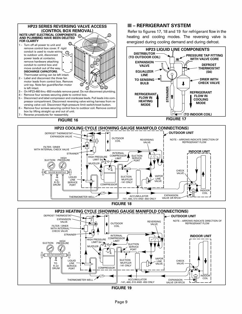
Page 9
1 – Turn off all power to unit andremove control box cover. If rigidconduit is used to route wiringto outdoor unit, disconnectpower leads at contactor,remove hardware attachingconduit to control box andmove conduit out of the way.DISCHARGE CAPACITORS.
Thermostat wiring can be left intact. 2 – Label and disconnect the three fan
motor leads from control box. Removeunit top. Note-fan guard/fan/fan motoris left intact.
3 – On HP23-460 thru -650 models remove panel. Do not disconnect plumbing. 4 – Remove four screws securing plate to control box. 5 – Disconnect and label compressor and crankcase leads. Pull leads into com-
pressor compartment. Disconnect reversing valve wiring harness from re-versing valve coil. Disconnect High-pressure limit switch/rexet button.
6 – Remove four screws securing control box to outdoor coil. Remove controlbox by lifting straight up and out of unit.
7 – Reverse procedures for reassembly.
HP23 SERIES REVERSING VALVE ACCESS(CONTROL BOX REMOVAL)
FIGURE 16
NOTE-UNIT ELECTRICAL COMPONENTSAND PLUMBING HAVE BEEN DELETEDFOR CLARITY
III – REFRIGERANT SYSTEM
Refer to figures 17, 18 and 19 for refrigerant ���� �� ��
����� ��� ������ ����� �� �������� ����� ��
�������� ����� ������ �� ��� ��� ����� ��������
FIGURE 17
EXPANSIONVALVE
EQUALIZERLINE
DRIER WITHCHECK VALVE
PRESSURE TAP FITTINGWITH VALVE CORE
DISTRIBUTOR(TO OUTDOOR COIL)
ST
RA
INE
R
HP23 LIQUID LINE COMPONENTS
REFRIGERANTFLOW INCOOLING
MODE
REFRIGERANTFLOW INHEATING
MODE
TO SENSINGBULB
(TO INDOOR COIL)
DEFROSTTHERMOSTAT
(S6)
OUTDOORCOIL
HP23 COOLING CYCLE (SHOWING GAUGE MANIFOLD CONNECTIONS)
DEFROST THERMOSTATEXPANSION VALVE
FILTER / DRIERWITH INTERNAL CHECK VALVE
STRAINER
TOR–22
DRUM
SUCTIONHIGH
PRESSURE
COMPRESSOR
REVERSINGVALVE
VAPORLINE
VALVE
MUFFLER
CHECKVALVE
NOTE – ARROWS INDICATE DIRECTION OFREFRIGERANT FLOW
SERVICEPORT
SUCTION
FIGURE 18
INDOOR UNIT
OUTDOOR UNIT
LIQUIDLINE
SERVICEPORT
INDOORCOIL
THERMOMETER WELL
INTERNALCOMPRESSOR
LIMIT
EXPANSIONVALVE OR RFCIII
SUCTIONMUFFLER
-141 ONLY
ACCUMULATOR-141,-460,-510 AND -650 ONLY
HIGH PRESSURELIMIT S4
OUTDOORCOIL
HP23 HEATING CYCLE (SHOWING GAUGE MANIFOLD CONNECTIONS)DEFROST THERMOSTAT
EXPANSIONVALVE
FILTER / DRIERWITH INTERNAL
CHECK VALVE
STRAINER
TOR–22
DRUM
HIGHPRESSURE
COMPRESSOR
REVERSINGVALVE
VAPORLINE
VALVE
MUFFLER
CHECKVALVE
NOTE – ARROWS INDICATE DIRECTION OFREFRIGERANT FLOW
SERVICEPORT
SUCTION
FIGURE 19
INDOOR UNIT
OUTDOOR UNIT
LIQUIDLINE
SERVICEPORT
INDOORCOIL
THERMOMETER WELL
INTERNALCOMPRESSOR
LIMIT
EXPANSIONVALVE OR RFCIII
SUCTION
SUCTIONMUFFLER
-141 ONLY
ACCUMULATOR-141,-460,-510 AND -650 ONLY
HIGH PRESSURELIMIT S4
Page 10
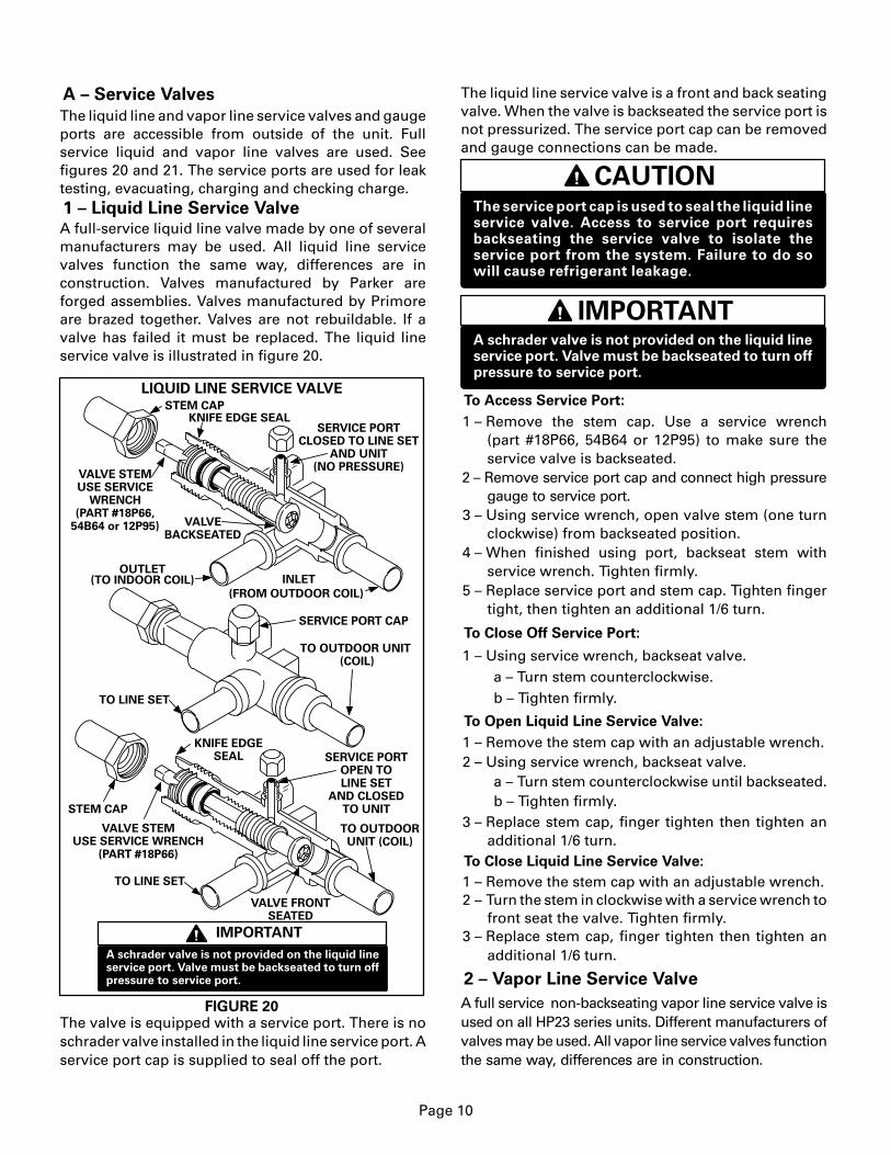
A – Service Valves
The liquid line and vapor line service valves and gaugeports are accessible from outside of the unit. Fullservice liquid and vapor line valves are used. Seefigures 20 and 21. The service ports are used for leaktesting, evacuating, charging and checking charge.1 – Liquid Line Service ValveA full-service liquid line valve made by one of severalmanufacturers may be used. All liquid line servicevalves function the same way, differences are inconstruction. Valves manufactured by Parker areforged assemblies. Valves manufactured by Primoreare brazed together. Valves are not rebuildable. If avalve has failed it must be replaced. The liquid lineservice valve is illustrated in figure 20.
KNIFE EDGE SEALSTEM CAP
VALVEBACKSEATED
INLET
(FROM OUTDOOR COIL)
OUTLET(TO INDOOR COIL)
SERVICE PORTCLOSED TO LINE SET
AND UNIT(NO PRESSURE)
SERVICE PORT CAP
TO OUTDOOR UNIT (COIL)
TO LINE SET
STEM CAP
KNIFE EDGESEAL
VALVE FRONTSEATED
TO LINE SET
SERVICE PORTOPEN TOLINE SET
AND CLOSEDTO UNIT
TO OUTDOORUNIT (COIL)
LIQUID LINE SERVICE VALVE
IMPORTANT
A schrader valve is not provided on the liquid lineservice port. Valve must be backseated to turn offpressure to service port.
FIGURE 20
VALVE STEMUSE SERVICE
WRENCH(PART #18P66,
54B64 or 12P95)
VALVE STEMUSE SERVICE WRENCH
(PART #18P66)
The valve is equipped with a service port. There is noschrader valve installed in the liquid line service port. Aservice port cap is supplied to seal off the port.
The liquid line service valve is a front and back seatingvalve. When the valve is backseated the service port isnot pressurized. The service port cap can be removedand gauge connections can be made.
CAUTIONThe service port cap is used to seal the liquid lineservice valve. Access to service port requiresbackseating the service valve to isolate theservice port from the system. Failure to do sowill cause refrigerant leakage.
IMPORTANTA schrader valve is not provided on the liquid lineservice port. Valve must be backseated to turn offpressure to service port.
To Access Service Port:
1 – Remove the stem cap. Use a service wrench(part #18P66, 54B64 or 12P95) to make sure theservice valve is backseated.
2 – Remove service port cap and connect high pressuregauge to service port.
3 – Using service wrench, open valve stem (one turnclockwise) from backseated position.
4 – When finished using port, backseat stem withservice wrench. Tighten firmly.
5 – Replace service port and stem cap. Tighten fingertight, then tighten an additional 1/6 turn.
To Close Off Service Port:
1 – Using service wrench, backseat valve. a – Turn stem counterclockwise. b – Tighten firmly.
To Open Liquid Line Service Valve:
1 – Remove the stem cap with an adjustable wrench. 2 – Using service wrench, backseat valve.
a – Turn stem counterclockwise until backseated. b – Tighten firmly.
3 – Replace stem cap, finger tighten then tighten anadditional 1/6 turn.
To Close Liquid Line Service Valve:
1 – Remove the stem cap with an adjustable wrench. 2 – Turn the stem in clockwise with a service wrench to
front seat the valve. Tighten firmly. 3 – Replace stem cap, finger tighten then tighten an
additional 1/6 turn.
2 – Vapor Line Service Valve
A full service non-backseating vapor line service valve isused on all HP23 series units. Different manufacturers ofvalves may be used. All vapor line service valves functionthe same way, differences are in construction.

Page 11
Valves manufactured by Parker are forgedassemblies. Primore and Aeroquip valves arebrazed together. Valves are not rebuildable. If a valvehas failed it must be replaced. The vapor line servicevalve is illustrated in figure 21.The valve is equipped with a service port. A schradervalve is factory installed. A service port cap issupplied to protect the schrader valve fromcontamination and assure a leak free seal.
VAPOR LINE SERVICE VALVE (VALVE OPEN)
FIGURE 21
SCHRADER VALVE
SERVICE PORT
SERVICE PORTCAP
STEM CAP
SNAP RINGINSERT HEX WRENCHHERE (PART #49A71 AND
SERVICE WRENCH)
VAPOR LINE SERVICE VALVE (VALVE CLOSED)
INLET(FROM INDOOR COIL)
OUTLET(TO COMPRESSOR)
KNIFE EDGESEAL
SCHRADER VALVE OPENTO LINE SET WHENVALVE IS CLOSED(FRONT SEATED)
SERVICE PORT
SERVICE PORTCAP
(VALVEFRONT SEATED)
SNAP RING
STEMCAP
OUTLET(TO COMPRESSOR)
KNIFE EDGE SEAL
INLET(FROM INDOOR COIL)
INSERTHEX WRENCH HERE(PART #49A71 AND
SERVICEWRENCH)
To Access Schrader Port:
1 – Remove service port cap with an adjustable wrench. 2 – Connect gauge to the service port. 3 – When testing is completed, replace service port
cap. Tighten finger tight, then tighten anadditional 1/6 turn.
To Open Vapor Line Service Valve:
1 – Remove stem cap with an adjustable wrench. 2 – Using service wrench and 5/16” hex head
extension (part #49A71) back the stem outcounterclockwise until the valve stem just touchesthe retaining ring.
Do not attempt to backseat this valve. Attempts tobackseat this valve will cause snap ring to explodefrom valve body under pressure of refrigerant.Personal injury and unit damage will result.
DANGER
3 – Replace stem cap tighten firmly. Tighten fingertight, then tighten an additional 1/6 turn.
To Close Vapor Line Service Valve:
1 – Remove stem cap with an adjustable wrench.
2 – Using service wrench and 5/16” hex headextension (part #49A71) turn stem in clockwise toseat the valve. Tighten firmly.
3 – Replace stem cap. Tighten finger tight, thentighten an additional 1/6 turn.
B – Plumbing
See figures 22 and 23 for unit refrigerant components.Field refrigerant piping consists of liquid and vaporlines from the outdoor unit (sweat connections). UseLennox L10 series line sets as shown in table 7 or fieldfabricated refrigerant lines.
LineSet
Model No.
TABLE 7
HP23–141
Length ofVapor & Liq.
Lines (ft.)
LiquidLine
(o.d. ft.)
VaporLine
(o.d. ft.)
*Not Available **1/4 1/2L10–21–20L10–21–25L10–21–35L10–21–50
20253550
***5/16 5/85/85/85/8
***5/16***5/16***5/16
HP23–211
HP23–261
L10–41–20L10–41–30L10–41–40L10–41–50
20304050
3/8 3/43/43/43/4
3/83/83/8
HP23–311
HP23–410
L10–65–30L10–65–40L10–65–50
304050
3/8 7/87/87/8
3/83/8
HP23–460HP23–510
HP23–651 *Not Available 3/8 1–1/8*Field Fabricate
LINE SET SPECIFICATIONSCondensing
UnitModel No.
*** 3/8” x 5/16” reducer furnished to adapt unit to 5/16” line set.**3/8” x 1/4” reducer furnished to adapt unit to 1/4 field fabricated line set.
IV – CHARGING
Unit charge is based on a matching indoor coil andoutdoor coil with a 20 foot (6096mm) line set dependingon date of manufacture. For varying lengths of line set,refer to table 8.
Liquid LineSet Diameter
1/4 in. (6 mm)5/16 in. (8mm)3/8 in. (10 mm)
TABLE 8Ounce per 5 foot (ml per mm) adjust from
20 ft. (6096mm)*
1 ounce per 5 feet (30 ml per 1524 mm)
*If line set is greater than 20 ft. (6.10m) add this amount. If line set is lessthan 20 ft. (6.10m) subtract this amount
2 ounce per 5 feet (60 ml per 1524 mm)3 ounce per 5 feet (90 ml per 1524 mm)
Page 12
SENSINGBULB
SUCTION LINE
SUCTIONMUFFLER
DISTRIBUTOR
DEFROSTSWITCH S6
FILTER/DRIERW/INTERNALCHECK VALVE
ROTARY COMPRESSOR
VAPOR LINE FROMINDOOR COIL
LIQUID LINE FROM INDOOR COIL
ACCUMULATOR
REVERSING VALVE
MUFFLER
TO OUTDOOR COIL
EXPANSION VALVE
STRAINER
SERVICEVALVES
FIGURE 22
HP23-141 REFRIGERATION COMPONENTS
LIQUID LINESERVICE PORT
DISCHARGE LINESERVICE PORT
HIGH PRESSURESWITCH PORT
HIGH PRESSURELIMIT S4
RESET BUTTON
VAPOR LINE FROMINDOOR COIL
HP23-211 AND LARGER TYPICAL REFRIGERATION COMPONENTSSUCTION LINE
FIGURE 23
EXPANSION VALVE
COMPRESSOR
SENSING BULB
DISTRIBUTOR
SERVICEVALVES
ACCUMULATOR-460,-510 AND -650 ONLY
DEFROST SWITCH S6
FILTER/DRIERW/INTERNALCHECK VALVE
MUFFLER
LIQUID LINE FROMINDOOR COIL
TOOUTDOOR COIL
DISCHARGE LINESERVICE PORT
STRAINER
LIQUID LINESERVICE PORT
REVERSINGVALVE
HIGH PRESSURELIMIT S4
RESET BUTTON
HIGH PRESSURESWITCH PORT
A – Pumping Down System
CAUTIONDeep vacuum operation (operating compressorbelow 0 psig) can cause internal fusite arcingresulting in a damaged or failed compressor. Thistype of damage will result in denial of warrantyclaim.
The system may be pumped down when leak checkingthe line set and indoor coil or making repairs to the lineset or indoor coil.
1– Attach gauge manifold. 2– Front seat (close) liquid line valve. 3– Start outdoor unit in cooling mode. 4– Monitor suction gauge. Stop unit when 0 psig. is
reached. 5– Front seat (close) suction line valve.
Page 13
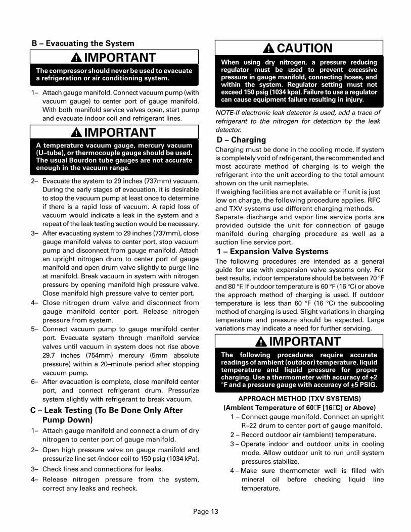
B – Evacuating the System
IMPORTANTThe compressor should never be used to evacuatea refrigeration or air conditioning system.
1– Attach gauge manifold. Connect vacuum pump (withvacuum gauge) to center port of gauge manifold.With both manifold service valves open, start pumpand evacuate indoor coil and refrigerant lines.
IMPORTANTA temperature vacuum gauge, mercury vacuum(U–tube), or thermocouple gauge should be used.The usual Bourdon tube gauges are not accurateenough in the vacuum range.
2– Evacuate the system to 29 inches (737mm) vacuum.During the early stages of evacuation, it is desirableto stop the vacuum pump at least once to determineif there is a rapid loss of vacuum. A rapid loss ofvacuum would indicate a leak in the system and arepeat of the leak testing section would be necessary.
3– After evacuating system to 29 inches (737mm), closegauge manifold valves to center port, stop vacuumpump and disconnect from gauge manifold. Attachan upright nitrogen drum to center port of gaugemanifold and open drum valve slightly to purge lineat manifold. Break vacuum in system with nitrogenpressure by opening manifold high pressure valve.Close manifold high pressure valve to center port.
4– Close nitrogen drum valve and disconnect fromgauge manifold center port. Release nitrogenpressure from system.
5– Connect vacuum pump to gauge manifold centerport. Evacuate system through manifold servicevalves until vacuum in system does not rise above29.7 inches (754mm) mercury (5mm absolutepressure) within a 20–minute period after stoppingvacuum pump.
6– After evacuation is complete, close manifold centerport, and connect refrigerant drum. Pressurizesystem slightly with refrigerant to break vacuum.
C – Leak Testing (To Be Done Only After
Pump Down)
1– Attach gauge manifold and connect a drum of drynitrogen to center port of gauge manifold.
2– Open high pressure valve on gauge manifold andpressurize line set /indoor coil to 150 psig (1034 kPa).
3– Check lines and connections for leaks.
4– Release nitrogen pressure from the system,correct any leaks and recheck.
CAUTIONWhen using dry nitrogen, a pressure reducingregulator must be used to prevent excessivepressure in gauge manifold, connecting hoses, andwithin the system. Regulator setting must notexceed 150 psig (1034 kpa). Failure to use a regulatorcan cause equipment failure resulting in injury.
NOTE-If electronic leak detector is used, add a trace ofrefrigerant to the nitrogen for detection by the leakdetector.
D – Charging
Charging must be done in the cooling mode. If systemis completely void of refrigerant, the recommended andmost accurate method of charging is to weigh therefrigerant into the unit according to the total amountshown on the unit nameplate.If weighing facilities are not available or if unit is justlow on charge, the following procedure applies. RFCand TXV systems use different charging methods.Separate discharge and vapor line service ports areprovided outside the unit for connection of gaugemanifold during charging procedure as well as asuction line service port.1 – Expansion Valve Systems
The following procedures are intended as a generalguide for use with expansion valve systems only. Forbest results, indoor temperature should be between 70 °Fand 80 °F. If outdoor temperature is 60 °F (16 °C) or abovethe approach method of charging is used. If outdoortemperature is less than 60 °F (16 °C) the subcoolingmethod of charging is used. Slight variations in chargingtemperature and pressure should be expected. Largevariations may indicate a need for further servicing.
IMPORTANTThe following procedures require accuratereadings of ambient (outdoor) temperature, liquidtemperature and liquid pressure for propercharging. Use a thermometer with accuracy of +2°F and a pressure gauge with accuracy of +5 PSIG.
APPROACH METHOD (TXV SYSTEMS)
(Ambient Temperature of 60�F [16�C] or Above)
1 – Connect gauge manifold. Connect an uprightR–22 drum to center port of gauge manifold.
2 – Record outdoor air (ambient) temperature. 3 – Operate indoor and outdoor units in cooling
mode. Allow outdoor unit to run until systempressures stabilize.
4 – Make sure thermometer well is filled withmineral oil before checking liquid linetemperature.
Page 14
5 – Place thermometer in well and read liquid linetemperature. Liquid line temperature should bea few degrees warmer than the outdoor airtemperature. Table 9 shows how many degreeswarmer the liquid line temperature should be.Add refrigerant to make the liquid linetemperature cooler.Recover refrigerant to make the liquid linetemperature warmer.
11HP23–411/413
TABLE 9
ModelLiquid Line °F Warmer Than Outside
(Ambient) Temperature
HP23–261HP23–311
HP23–411/413 (CAN)HP23–461/463
APPROACH METHOD – EXPANSION VALVE SYSTEMSAMBIENT TEMPERATURE OF 60 �F (16 �C) OR ABOVE
714
11
HP23–211 5HP23–141 6
HP23–511/513 11HP23–651/653 7
14
SUBCOOLING METHOD (TXV SYSTEMS)
(Ambient Temperature Below 60�F [16�C] )
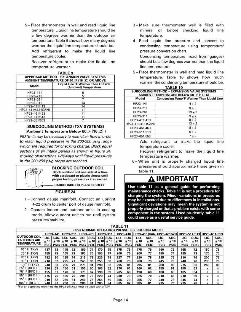
NOTE- It may be necessary to restrict air flow in orderto reach liquid pressures in the 200-250 psig rangewhich are required for checking charge. Block equalsections of air intake panels as shown in figure 24,moving obstructions sideways until liquid pressuresin the 200-250 psig range are reached.
Block outdoor coil one side at a timewith cardboard or plastic sheets untilproper testing pressures are reached.
BLOCKING OUTDOOR COIL
FIGURE 24
CARDBOARD OR PLASTIC SHEET
1 – Connect gauge manifold. Connect an uprightR–22 drum to center port of gauge manifold.
2 – Operate indoor and outdoor units in coolingmode. Allow outdoor unit to run until systempressures stabilize.
3 – Make sure thermometer well is filled withmineral oil before checking liquid linetemperature.
4 – Read liquid line pressure and convert tocondensing temperature using temperature/pressure conversion chart.Condensing temperature (read from gauges)should be a few degrees warmer than the liquidline temperature.
5 – Place thermometer in well and read liquid linetemperature. Table 10 shows how muchwarmer the condensing temperature should be.
TABLE 10
Model Condensing Temp°F Warmer Than Liquid Line
HP23–261HP23–311
HP23–411/413 (CAN)HP23–461/463
HP23–211HP23–141
HP23–511/513HP23–651/653
SUBCOOLING METHOD – EXPANSION VALVE SYSTEMSAMBIENT TEMPERATURE BELOW 60 �F (16 �C)
4 + 29 + 213 + 29 + 2
8 + 26 + 27 + 2
HP23–411/413 9 + 213 + 2
Add refrigerant to make the liquid linetemperature cooler.Recover refrigerant to make the liquid linetemperature warmer.
6 – When unit is properly charged liquid linepressures should approximate those given intable 11.
IMPORTANTUse table 11 as a general guide for performingmaintenance checks. Table 11 is not a procedure forcharging the system. Minor variations in pressuresmay be expected due to differences in installations.Significant deviations may mean the system is notproperly charged or that a problem exists with somecomponent in the system. Used prudently, table 11could serve as a useful service guide.
73
PSIG
285 84
HP23 NORMAL OPERATING PRESSURES (COOLING MODE)
OUTDOOR COILENTERING AIRTEMPERATURE
HP23–141 HP23–261 HP23–311 HP23–410
65° F (TXV)75° F (TXV)85° F (TXV)95° F (TXV)
LIQ.+ 10
SUC.+ 10
PSIG PSIG
LIQ.+ 10
SUC.+ 10
PSIG PSIG
LIQ.+ 10
SUC.+ 10
PSIG PSIG
105° F (TXV)
LIQ.+ 10
SUC.+ 10
PSIG PSIG
LIQ.+ 10
SUC.+ 10
PSIG PSIG
HP23–211 HP23–461/463 HP23–511/513 HP23–651/653
LIQ.+ 10
SUC.+ 10
PSIG PSIG
LIQ.+ 10
PSIG
SUC.+ 10
SUC.+ 10
PSIG
LIQ.+ 10
PSIG
105° F (RFC III)95° F (RFC III)85° F (RFC III)75° F (RFC III)65° F (RFC III)
TABLE 11
137
155
182
210
240130
175
155
210240
78
79
80
82
8359
75
67
8287
145
165
195
225
255150
195
170
230260
72
73
74
77
7961
75
68
8185
160
185
215
245
275150
205
175
240280
74
76
78
80
8460
73
67
7881
170
195
225
255
290165
220
190
255
75
77
78
80
8262
74
69
80
175
200
227
260
295170
230
205
265305
75
76
77
79
8161
73
68
7982
160
185
215
245
280155
210
180
240275
72
74
76
78
8061
68
63
7376
165
185
210
240
275155
210
185
245275
72
73
76
78
8063
69
64
7478
150
175
200
235
265
75
76
78
80
* ** ** ** ** *
*For an approved match-up the HP23-651/653 must be used with a TXV.
HP23–410 (CAN)
LIQ.+ 10
SUC.+ 10
PSIG PSIG
175
200
230
260
295160
225
190
255385
76
77
78
79
8162
70
68
7781
Page 15
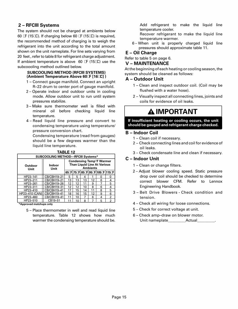
2 – RFCIII Systems
The system should not be charged at ambients below60 �F (15�C). If charging below 60 �F (15�C) is required,the recommended method of charging is to weigh therefrigerant into the unit according to the total amountshown on the unit nameplate. For line sets varying from20 feet , refer to table 8 for refrigerant charge adjustment.If ambient temperature is above 60 �F (15�C) use thesubcoooling method outlined below.
SUBCOOLING METHOD (RFCIII SYSTEMS)(Ambient Temperature Above 60�F [16�C] )
1 – Connect gauge manifold. Connect an uprightR–22 drum to center port of gauge manifold.
2 – Operate indoor and outdoor units in coolingmode. Allow outdoor unit to run until systempressures stabilize.
3 – Make sure thermometer well is filled withmineral oil before checking liquid linetemperature.
4 – Read liquid line pressure and convert tocondensing temperature using temperature/pressure conversion chart.Condensing temperature (read from gauges)should be a few degrees warmer than theliquid line temperature.
OutdoorUnit
IndoorUnit
65�F 75�F 85�F 95�F 105�F 115�F
CB19–51HP23–510
HP23–141HP23–211HP23–261
HP23–410 (CAN) CB/CBH19–41
CB/CBH19–26CB/CBH19–21CB/CBH19–21
CB/CBH19–31
CB/CBH19–41
HP23–311
HP23–460
SUBCOOLING METHOD––RFCIII Systems*
5131212
1111
5131212
1010
4131110
78
11298
67
0676
45
0454
22
*Approved matchups only
HP23–410 CB/CBH19–41 17 15 14 11 8 518 16 15 12 9 6
Condensing Temp°F WarmerThan Liquid Line At Various
Ambients
����� ��
5 – Place thermometer in well and read liquid linetemperature. Table 12 shows how muchwarmer the condensing temperature should be.
Add refrigerant to make the liquid linetemperature cooler.Recover refrigerant to make the liquid linetemperature warmer.
6 – When unit is properly charged liquid linepressures should approximate table 11.
E – Oil ChargeRefer to table 5 on page 6.V – MAINTENANCEAt the beginning of each heating or cooling season, thesystem should be cleaned as follows:A – Outdoor Unit
1 – Clean and inspect outdoor coil. (Coil may beflushed with a water hose).
2 – Visually inspect all connecting lines, joints andcoils for evidence of oil leaks.
IMPORTANTIf insufficient heating or cooling occurs, the unitshould be gauged and refrigerant charge checked.
B – Indoor Coil 1 – Clean coil if necessary. 2 – Check connecting lines and coil for evidence of
oil leaks. 3 – Check condensate line and clean if necessary.
C – Indoor Unit
1 – Clean or change filters.
2 – Adjust blower cooling speed. Static pressuredrop over coil should be checked to determinecorrect blower CFM. Refer to LennoxEngineering Handbook.
3 – Belt Drive Blowers - Check condition andtension.
4 – Check all wiring for loose connections.
5 – Check for correct voltage at unit.
6 – Check amp–draw on blower motor.Unit nameplate_________Actual_________.
Page 16
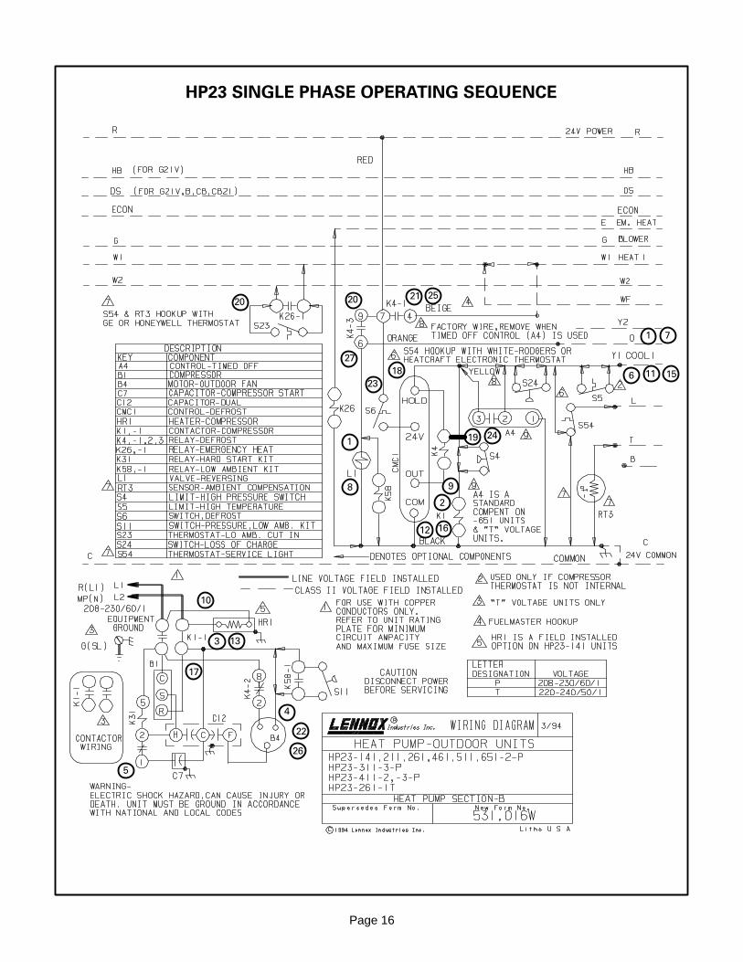
HP23 SINGLE PHASE OPERATING SEQUENCE
1
2
3
5
6
4
7
8 9
10
11
12
13
15
16
17
18
19
2021
22
23
24
25
27
26
1
20

Page 17
HP23 SINGLE PHASE OPERATING SEQUENCE
A–HP23 P Voltage Operation Sequence
This is the sequence of operation for HP23 “P” voltageunits. The sequence is outlined by numbered stepswhich correspond to circled numbers on the adjacentdiagram.NOTE– The thermostat used may be electromechan-ical or electronic.NOTE– Transformer in indoor unit supplies power (24VAC) to the thermostat and outdoor unit controls.
COOLING:
1 – Cooling demand initiates at Y1 in the thermostat.Internal thermostat wiring energizes terminal Oenergizing the reversing valve L1.
2 – 24VAC energizes compressor contactor K1.3 – K1-1 N.O. closes energizing compressor (B1) and
outdoor fan motor (B4).4 – Outdoor fan motor (B4) begins immediate op-
eration.5 – Compressor (B1) begins start-up. Hard start
contactor K31 remains closed during start-upand start capacitor C7 remains in the circuit. Asthe compressor gains speed, K31 is energized.When K31 is energized the contacts open andstart capacitor C7 is taken out of the circuit.
END OF COOLING DEMAND:
6 – Cooling demand is satisfied. Terminal Y1 is de-en-ergized.
7 – Thermostat terminal O is de-energized.8 – Reversing valve L1 is de-energized9 – Compressor contactor K1 is de-energized.
10 – K1-1 opens and compressor (B1) and outdoorfan motor (B4) are de-energized and stop im-mediately.
FIRST STAGE HEAT:
11 – Heating demand initiates at W1 in the ther-mostat.
12 – 24VAC energizes compressor contactor K1.
13 – K1-1 N.O. closes energizing compressor andoutdoor fan motor.
14 – See steps 4 and 5.END OF FIRST STAGE HEAT:
15 – Heating demand is satisfied. Terminal W1 isde-energized.
16 – Compressor contactor K1 is de-energized.
17 – K1-1 opens and compressor (B1) and outdoorfan motor (B4) are de-energized and stop im-mediately.
DEFROST MODE:
18 – During heating operation when outdoor coil tem-perature drops below 35� + 4 �F Defrost Switch(thermostat) S6 closes.
19 – Defrost control CMC1 begins timing. If defrostthermostat (S6) remains closed at the end ofthe 30,60 or 90 minute period, defrost relay K4energizes and defrost begins.
20 – N.O. K4-3 closes energizing the reversing valve.
21 – N.O. K4-1 closes energizing W1 on TB1 terminalstrip of indoor unit. Indoor unit operates in thefirst stage heat mode.
22 – N.C. K4-2 opens and outdoor fan motor B4 stops.
23 – Defrost continues 14 + 1 minutes or until ther-mostat switch (S6) opens. When defrost ther-mostat opens defrost control CMC1 losespower and resets.
24 – Defrost relay K4 is de-energized.
25 – K4-1 opens and W1 on terminal strip TB1 ofindoor unit is de-energized.
26 – K4-2 closes and the outdoor fan begins operation.
27 – K4-3 opens de-energizing the reversing valve.
Page 18
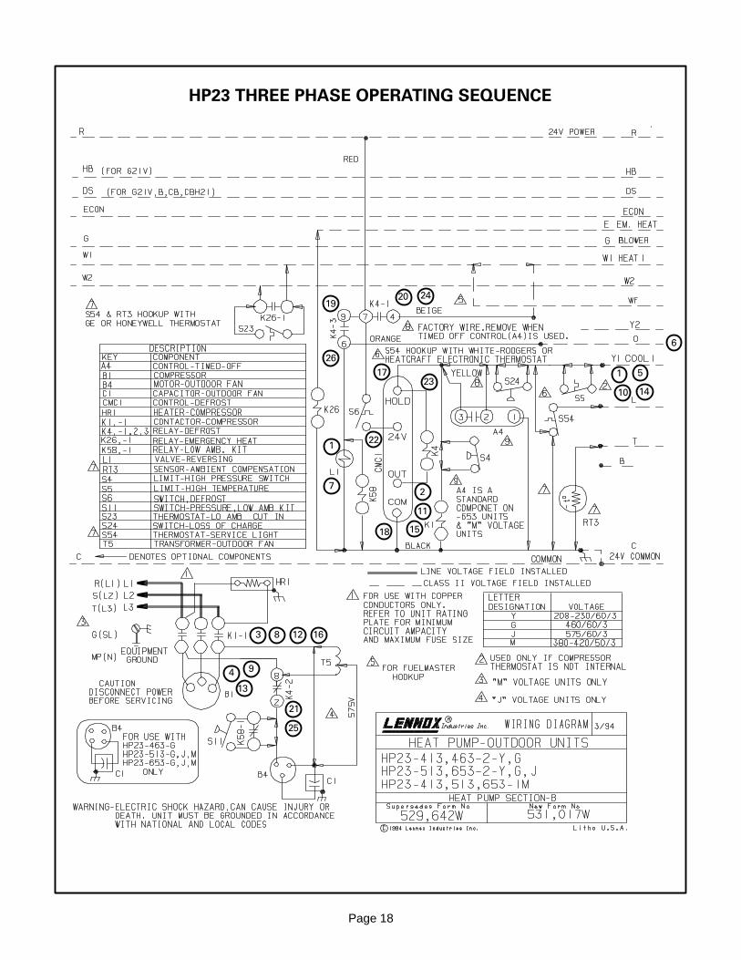
HP23 THREE PHASE OPERATING SEQUENCE
1
2
3
5
6
4
7
8
9
10
11
12
13
15
14
16
17
18
1920
21
22
23
24
25
26
1
Page 19
HP23 THREE PHASE OPERATING SEQUENCE
A–HP23 P Voltage Operation Sequence
This is the sequence of operation for HP23 “Y”, “G”,and “J” voltage units. The sequence is outlined bynumbered steps which correspond to circled num-bers on the adjacent diagram.NOTE– The thermostat used may be electrome-chanical or electronic.NOTE– Transformer in indoor unit supplies power (24VAC) to the thermostat and outdoor unit controls.
COOLING:
1 – Cooling demand initiates at Y1 in the thermostat.Internal thermostat wiring energizes terminal Oenergizing the reversing valve L1.
2 – 24VAC energizes compressor contactor K1.3 – K1-1 N.O. closes energizing compressor (B1) and
outdoor fan motor (B4).4 – Compressor (B1) and outdoor fan motor (B4)
begin immediate operation.END OF COOLING DEMAND:
5 – Cooling demand is satisfied. Terminal Y1 isde-energized.
6 – Thermostat terminal O is de-energized.7 – Reversing valve L1 is de-energized8 – Compressor contactor K1 is de-energized.9 – K1-1 opens and compressor (B1) and outdoor
fan motor (B4) are de-energized and stop im-mediately.
FIRST STAGE HEAT:
10 – Heating demand initiates at W1 in the ther-mostat.
11 – 24VAC energizes compressor contactor K1.12 – K1-1 N.O. closes energizing compressor
and outdoor fan motor.
13 – Compressor (B1) and outdoor fan motor (B4)begin immediate operation.
END OF FIRST STAGE HEAT:
14 – Heating demand is satisfied. Terminal W1 isde-energized.
15 – Compressor contactor K1 is de-energized.16 – K1-1 opens and compressor (B1) and outdoor
fan motor (B4) are de-energized and stop im-mediately.
DEFROST MODE:
17 – During heating operation when outdoor coiltemperature drops below 35� + 4 �F DefrostSwitch (thermostat) S6 closes.
18 – Defrost control CMC1 begins timing. If defrostthermostat (S6) remains closed at the end ofthe 30,60 or 90 minute period, defrost relay K4energizes and defrost begins.
19 – N.O. K4-3 closes energizing the reversing valve.20 – N.O. K4-1 closes energizing W1 on TB1 terminal
strip of indoor unit. Indoor unit operates in thefirst stage heat mode.
21 – N.C. K4-2 opens and outdoor fan motor B4 stops.22 – Defrost continues 14 + 1 minutes or until ther-
mostat switch (S6) opens. When defrost ther-mostat opens defrost control CMC1 losespower and resets.
23 – Defrost relay K4 is de-energized.24 – K4-1 opens and W1 on terminal strip TB1 of
indoor unit is de-energized.25 – K4-2 closes and the outdoor fan begins operation.26 – K4-3 opens de-energizing the reversing valve.