hp100 - state · pdf filehp100-p hp100-p hp100-p hp100-p hp100-p hp100-t ... state electroncs...
TRANSCRIPT

1
CLICKCLICKCLICK
Mounting holes are 25.4mm apart, based on industrial standards
IP67 sealing and single-piece molding
HP100 Series
Effective light axis alignment 50% power savings Prevention of accidental switch operation Guaranteed wide operating temperature range Longest scanning distance in the industry No damage from any wiring error Reduced operating error due to noise Error due to ambient light greatly reduced Significant reduction in error due to sensor mutual interference
General-Purpose Photoelectric Sensors with Self-Contained Amplifier
The convenience of industry standards, plus reliability.
EXPLANATION OF MAJOR FUNCTIONS AND FEATURES
Mutual interference prevention function
Light-operated indicator in front for easy light axis alignment
Industry-standard height, width and thickness
Distributed by: State Electroncs 1301 Potomac Ave. Hagerstown, MD 21742 Tel 301-739-6460 fax:301-739-5311 shop.stateelect.com

2
Conventionalmodel
HP100 x 2
Conventionalmodel
HP100
Conventionalmodel
HP100
Comparison with Yamatake'sconventional model [2 times the scanning distance]
5m
The HP100 can solve problems with
Longest scanning distance in the industry!
Environment
Environment
Environment
Large reduction of operation error caused by ambient light!
Significant reduction in operation errors due to mutual interference between sensors!
Effective light axis alignment! Putting a light-operated indicator in front ensures reliable confirmation of indicator operation by only one person.
Reduction of operation error caused by noise!
Adjustment
Adjustment
Interference
Interference Interference
Installation
Installation
Prevention of accidental switch operation!
Installation
50% power savings compared with Yamatake's conventional model!
Installation
Guaranteed wide operating temperature range!
!
Sensor has a light-operated indicator in front.
After installation by only one operator, everything checks out!
sunlight40,000 lux!
Even with this type of mounting,the HP100 performs reliably.
No damage from any wiring error!
Installation
Oh no, sensor'sbroken...
No problem.
Wiring screwup!
The output selector switch is on the bottom to prevent operator error.
Distributed by: State Electroncs 1301 Potomac Ave. Hagerstown, MD 21742 Tel 301-739-6460 fax:301-739-5311 shop.stateelect.com

3
Name Shape Description Catalog listing Applicable model
HP100-P
HP100-P
HP100-P
HP100-P
HP100-P
HP100-T
HP100-T
HP100-T
All models
All models
All models
All models
Reflector size47 x 47mm
FE-RR8Scanning distance 5m
Reflector size47 x 47mm
FE-RR17Scanning distance 5m
FE-RR15Scanning distance 3.5m
FE-RR18Scanning distance 3.5m
FE-RR20Scanning distance 2m
Reflector for polarizedretroreflective model
Reflector size30.8 x 30.8mm
Reflector size30.8 x 30.8mm
Reflector size8.6mm x 29.5mm
Standard bracket
Bottom-mounting L-bracket(material: SUS)
HP100-B01
Rear-mounting L-bracket (material: SUS)
HP100-B04
Wraparound mountingbracket
Wraparound vertical mounting bracket (material: SUS)
HP100-B02
Wraparound horizontal mounting bracket (material: SUS)
HP100-B03
Slit bracketfor thru-scan model
Vertical slit bracket(0.5mm / 1mm / 1.5mm / 2mm)
HP100-SV05 / SV10 / SV15 / SV20
Horizontal slit bracket(0.5mm / 1mm / 1.5mm / 2mm)
Mutual interference can be prevented by changing the plane of polarization
of 2 sets of adjacent emitter and receiver
HP100-SH05 / SH10 / SH15 / SH20
Mutual interference protection filter for thru-scan model HP100-U01
Accessories
CATALOG LISTINGS
Scanning distance L-ON / D-ONselection
Sensitivityadjustment
Powersupply
Output mode Catalog listingDetection method
Thru-scan
Polarized retroreflective
Diffuse-scan
15m
1m
5m(when used with FE-RR8 or FE-RR17) 10 to 30Vdc
NPN open collector PNP open collector NPN open collector PNP open collector NPN open collector PNP open collector
HP100-T1HP100-T2HP100-P1HP100-P2HP100-A1HP100-A2
Pre-leaded type (2m)
Notes: 1. denotes availability. 2. An FET is used for output.
Pre-leaded type (50cm, 5m) and pre-leaded connector type (30cm, 50cm, 1m)
Length HP100-T -model HP100-P/A -modelType
Pre-leaded connector
Pre-leaded connector(DIN M12 connector is used)
50cm5m
30cm50cm1m
HP100-T -LP5HP100-T -L05HP100-T -CN03HP100-T -CN05HP100-T -CN1
HP100-P/A -LP5HP100-P/A -L05HP100-P/A -CN03HP100-P/A -CN05HP100-P/A -CN1
Distributed by: State Electroncs 1301 Potomac Ave. Hagerstown, MD 21742 Tel 301-739-6460 fax:301-739-5311 shop.stateelect.com

4
–400
–350–300–250
–200
400350300250200150100500
–50–100–150
Par
alle
l mot
ion
dist
ance
(m
m)
Distance (m)
Distance (m)
1
1000
100
10
Ligh
t re
ceiv
ing
leve
l
1
100
10
Ligh
t re
ceiv
ing
leve
l
Distance (m)
Distance (m)
Distance (m)
–160–140–120–100–80
160140120100806040200
–20–40–60
Par
alle
l mot
ion
dist
ance
(m
m)
–25
–20
25
20
15
10
5
0
–5
–10
–15
Par
alle
l mot
ion
dist
ance
(m
m)
Ligh
t re
ceiv
ing
leve
l
1
100
10
0 5 10 15 20
Distance (m)
0 2 3 4 5 61 0 0.5 1
0 0.5 10 2 3 4 5 610 5 10 15 20
Thru-scan model (HP100-T)
Polarized retroreflective model (HP100-P)
Diffuse-scan model (HP100-A)
Parallel motion characteristics Parallel motion characteristicsCombined with FE-RR8 or with FE-RR15
Excess gain (Light receiving level margin) Combined with FE-RR8 or with FE-RR15
Detection area characteristics
Excess gain (Light receiving level margin) Excess gain (Light receiving level margin)
RR8 in right and left directionsRR8 in up and down directionsRR15 in right and left directionsRR15 in up and down directions
RR8RR15
Right and left directionsUp and down directions
HP100-P1 HP100-P2 HP100-T1 HP100-T2 HP100-A1 HP100-A2Catalog listingDetection systemPower supply
Current consumption
Scanning distance
Target object
Standard target objectScanning angleDifferential travelOperation modeOutput mode (Note 1)
Control output
Response timeEmitter
Indicator
Ambient light immunityOperating temperatureOperating humidityStorage temperatureInsulation resistanceDielectric strengthVibration resistance Shock resistanceSealing
Wiring method
WeightProtection circuit
Polarized retroreflective
13mA max.
5m(when used with reflector FE-RR8 or FE-RR17)
Opaque object 80mm dia. min. (when used with reflector FE-RR8 or FE-RR17)
Body: 1 to 10˚ Reflector: 30˚ min.
Thru-scan
15m
Opaque object 9mm dia. min.
2 to 20˚
HP100-E1: 16mA max.HP100-R : 11mA max.
Diffuse-scan
16mA max.
1m
300 x 300mm white paper (Kodak 90% reflective paper)
20% max. (at rated scanning distance)
10 to 30Vdc (ripple 10% max.)
Light-ON / Dark-ON selectable by switchHP100- 1: NPN open collector HP100- 2: PNP open collector
Switching current: 100mA (resistive load). Output dielectric strength:30V.Drop voltage: 3V max. (at switching current 100mA), with short-circuit protection function
500µs max. for both operation and recovery
Indicators other than thru-scan emitter: orange lit at output ON, and green lit at stable light-ON and light-OFF.Thru-scan emitter: orange light on power supply indicator. Thru-scan receiver: red light on front light-operated indicator.
Incandescent lamp: 10,000 lux max. Sunlight: 40,000 lux max.-30 to +60˚C (no condensation allowed)
35 to 85% RH (no condensation allowed)-40 to +70˚C (no condensation allowed)
20MΩ min. (at 500Vdc)1,000Vac 50/60Hz for one minute between electrically live metal and case
10 to 55Hz, 1.5mm peak-to-peak amplitude, 2 hours each in X, Y, and Z directions500m/s2 10 times each in X, Y and Z directions
IP67 (IEC standard)
Approx. 55g (body with 2m cable only)Power ON malfunction prevention circuit (approx. 8ms), wiring error protection
HP100- -LP5: pre-leaded (0.5m), HP100- : pre-leaded (2m), HP100- -L05: pre-leaded (5m), HP100- -CN03: pre-leaded connector (0.3m), HP100- -CN05: pre-leaded connector (0.5m),
HP100- -CN1: pre-leaded connector (1m)
Red LED Red LED Infrared LED
Note 1. An FET is used for output
SPECIFICATIONS
CHARACTERISTICS DIAGRAMS (typical examples)
Distributed by: State Electroncs 1301 Potomac Ave. Hagerstown, MD 21742 Tel 301-739-6460 fax:301-739-5311 shop.stateelect.com

5
25.4
29
8 14.5
5
7
74
43.5 25
.4
145
135
12.3
1.5
13.3
12
7.3
3.3
35.3
3225.4 25.4123.3
3.3 5 3.5
13.37.
3
32
5 3.5
3.3
35.3
6.6
25.4
6.6
15 22
13.8
4
5 4.5
4.5
4.5
4
3.5 7
5.45.4
4.5 (2)25.415.3 7
15
4.5
55
3.3
3.3 (4) 3.3 (4)
20.5
3.4 dia. hole (4)
35
7 (2)
553.4 (2)
25
HP100-P / HP100-A HP100-T (Emitter: HP100-E1) HP100-T (Receiver: HP100-R)
Bracket (sold separately)
Bottom-mounting L-bracket (HP100-B01) Rear-mounting L-bracket (HP100-B04)
Wraparound vertical mounting bracket (HP100-B02) Wraparound horizontal mounting bracket (HP100-B03)
Emitter
Receiver
Output indicator
Sensitivity adjustment potentiometer
Power supply indicator
Light axis of emitter
Sensitivity adjustment potentiometer
Stability indicator
M3 threadedthru hole (2)
10.8 20
172.4
2.8
25.4
4.2 di
a
31
15.5
3.8
3.8
10.4
Light-ON
Dark-ONOperation selector switch
Output indicator
Stability indicator
15.5
Output indicator
Light axis of receiver
15.5
Light-ON
Dark-ON Operation selector switch
EXTERNAL DIMENSIONS (unit: mm)
Distributed by: State Electroncs 1301 Potomac Ave. Hagerstown, MD 21742 Tel 301-739-6460 fax:301-739-5311 shop.stateelect.com
6
(base)
5.5
8
30 0.2 (2)
3.5
51.15
51.1
5
47
4761
4.5 ± 0.2 dia. hole (2) 40
30.4
62
Acrylic resin(transparent)
7.5
47 51
4 7.3
72
51
47ABS resin (black)
8 dia. (2)
4.6 di
a.
hole
(2)
Acrylic resin (transparent)
(30.8)
45
55
(30.
8
)
35
ABS resin (black)
7.5
4
7.3
4.6 dia. hole (2)
8 dia. (2)
42 35.0
5
30.9
30.9
35.05
15
5.5
0.2 (2)
3.5
(base)
8
3.6 ± 0.2 dia. hole (2) 25
21
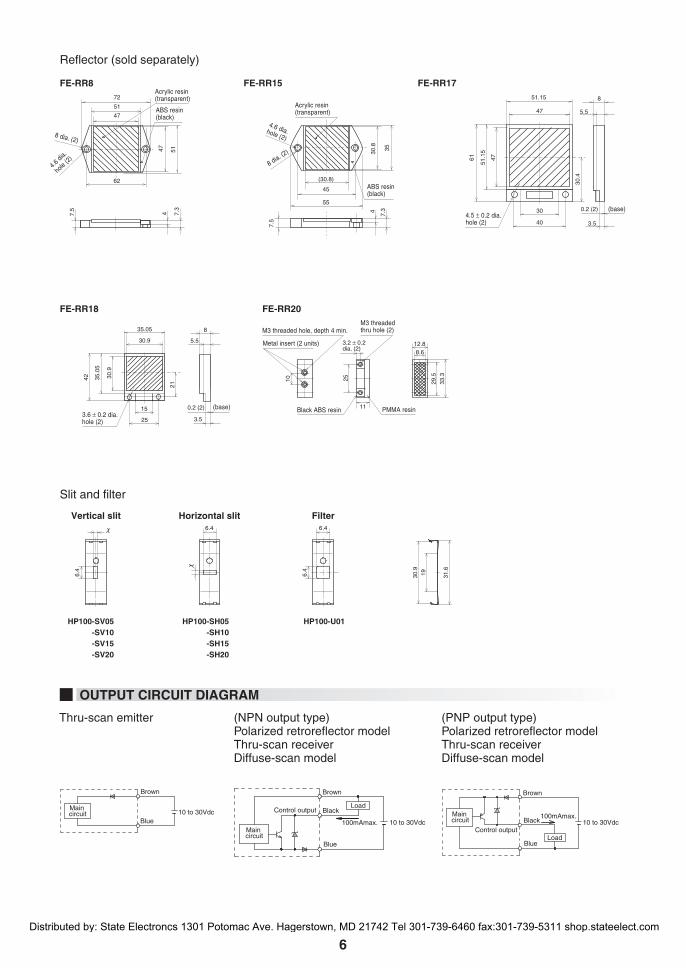
Reflector (sold separately)
FE-RR8 FE-RR15 FE-RR17
FE-RR18 FE-RR20
Vertical slit
HP100-SV05 -SV10 -SV15 -SV20
HP100-SH05 -SH10 -SH15 -SH20
HP100-U01
Horizontal slit Filter
Slit and filter
Thru-scan emitter (NPN output type)Polarized retroreflector modelThru-scan receiverDiffuse-scan model
(PNP output type)Polarized retroreflector modelThru-scan receiverDiffuse-scan model
Main circuit
Main circuit
Main circuit
Brown
10 to 30VdcBlue
Control output
Brown
Load
100mAmax. 10 to 30Vdc
Black
Blue
Control output
Brown
Load
100mAmax.10 to 30VdcBlack
Blue
Metal insert (2 units)
M3 threaded thru hole (2)
Black ABS resin
M3 threaded hole, depth 4 min.
3.2 ± 0.2 dia. (2)
10 25
11 PMMA resin
12.88.6
29.5
33.3
6.4 6.4
6.4
6.4
30.9
19 31.6
OUTPUT CIRCUIT DIAGRAM
Distributed by: State Electroncs 1301 Potomac Ave. Hagerstown, MD 21742 Tel 301-739-6460 fax:301-739-5311 shop.stateelect.com