hp xw9400 workstation service and technical reference...
TRANSCRIPT

HP xw9400 Workstation Service andTechnical Reference Guide
User Guide

Copyright Information
© 2006 Copyright Hewlett-PackardDevelopment Company, L.P.
Warranty
Hewlett-Packard Company shall not be liablefor technical or editorial errors or omissionscontained herein or for incidental orconsequential damages in connection withthe furnishing, performance, or use of thismaterial. The information in this document isprovided “as is” without warranty of any kind,including, but not limited to, the impliedwarranties of merchantability and fitness fora particular purpose, and is subject tochange without notice. The warranties for HPproducts are set forth in the express limitedwarranty statements accompanying suchproducts.
Nothing herein should be construed asconstituting and additional warranty.
This document contains proprietaryinformation that is protected by copyright. Nopart of this document may be photocopied,reproduced, or translated to anotherlanguage without the prior written consent ofHewlett-Packard Company.
Trademark Credits
The HP Invent logo is a trademark of Hewlett-Packard Company in the U.S. and othercountries.
Microsoft and Windows are trademarks ofMicrosoft Corporation.
UNIX is a registered trademark of The OpenGroup..
Intel and Xeon are registered trademarks ofIntel Corporation in the U.S. and othercountries.
Energy Star is U.S. registered mark of theUnited States Environmental ProtectionAgency.
434615-001
First Edition, September 2006
Table of contents
1 Product overviewProduct features ................................................................................................................................... 2
Exploded view ...................................................................................................................... 2Front panel components ..................................................................................................... 3Rear panel components ...................................................................................................... 4Serial number and COA label location ................................................................................. 5
Product specifications ......................................................................................................................... 6Power supply and cooling .................................................................................................... 6
Power supply specifications ................................................................................ 7Power consumption and cooling ........................................................................ 8System fans and airflow ..................................................................................... 9Resetting the power supply ................................................................................ 9Power cord requirements .................................................................................... 9
Environmental specifications .............................................................................................. 9PCI card slot power specification ....................................................................................... 10
Chipkill support ................................................................................................................................... 12Energy Star® ..................................................................................................................................... 13
Energy Star compliance ..................................................................................................... 13
2 Installing or restoring the operating systemInstalling the operating system and software ..................................................................................... 16
Microsoft Windows XP Professional ................................................................................. 16Installing or upgrading device drivers ................................................................ 16
Linux-preinstalled workstations .......................................................................................... 16Starting the Linux operating system .................................................................. 16Upgrading device drivers .................................................................................. 16
Linux-enabled workstations ............................................................................................... 17Verifying hardware compatibility ....................................................................... 17Installing the Linux operating system ................................................................ 17Red Hat Activation ............................................................................................ 17
HP software ........................................................................................................................................ 18Restoring the operating system .......................................................................................................... 19
Restoring the Windows operating system ......................................................................... 19The RestorePlus! process ................................................................................. 19
Creating a RestorePlus! CD ............................................................. 19Restoring from RestorePlus! CDs .................................................... 19Restoring from RestorePlus! on the Recovery Partition ................... 19
HP Backup and Recovery Manager restore points ........................................... 20
ENWW iii

Restoring from the HP Backup and Recovery Manager restorepoint CD/DVDs ................................................................................. 20Restoring from the HP Backup and Recovery Manager restorepoint on the Recovery Partition ........................................................ 20
Reclaiming hard disk space from the recovery partition ................................... 20Ordering backup software ................................................................................. 20
Restoring the Linux operating system ............................................................................... 21Downloading the latest HP driver CD contents ................................................. 21Installing the operating system with the HP driver CD contents ....................... 21
Protecting the software ....................................................................................................................... 22
3 System managementComputer Setup (F10) Utility .............................................................................................................. 24
BIOS ROM ......................................................................................................................... 25Using Computer Setup (F10) Utility .................................................................................. 25Computer Setup (F10) Utility menu .................................................................................. 26
Desktop management ........................................................................................................................ 34Initial configuration and deployment .................................................................................. 34Remote system installation ................................................................................................ 34Managing and updating software ....................................................................................... 35
HP Client Manager software ............................................................................. 35Altiris Client Management solutions .................................................................. 35System Software Manager ................................................................................ 36Proactive Change Notification ........................................................................... 36Subscriber’s Choice .......................................................................................... 36
ROM flash .......................................................................................................................... 37Remote ROM flash ............................................................................................ 37HPQFlash .......................................................................................................... 37FailSafe Boot Block ROM ................................................................................. 37Replicating the setup ......................................................................................... 38
Copying to a single workstation ........................................................ 39Copying to multiple workstations ...................................................... 39
Dual-state power button .................................................................................... 40Worldwide web site ........................................................................................... 40Building blocks and partners ............................................................................. 41
Asset tracking and security ................................................................................................ 41Password security ............................................................................................ 42
Establishing a setup password in the Computer Setup (F10)Utility ................................................................................................. 43Establishing a power-on password in the Computer Setup (F10)Utility ................................................................................................. 43Entering a power-on password ......................................................... 44Entering a setup password ............................................................... 44Changing a power-on or setup password ......................................... 44
Deleting a power-on or setup password ............................................................ 45National keyboard delimiter characters ............................................ 45Clearing passwords .......................................................................... 46
Hood sensor (Smart Cover Sensor) ................................................................. 46Setting the hood sensor protection level ......................................... 46
Cable lock provision (optional) .......................................................................... 47
iv ENWW

Security lock (optional) ...................................................................................... 47Universal chassis clamp lock (optional) ............................................................ 47Access panel key lock ....................................................................................... 47
Fault notification and recovery ........................................................................................... 47Drive Protection System .................................................................................... 47ECC fault prediction and pre-failure warranty ................................................... 47Thermal sensors .............................................................................................. 48
4 Removal and replacement proceduresService considerations ....................................................................................................................... 50
Read cautions, warnings, and safety precautions ............................................................. 50Electrostatic discharge information .................................................................................... 50
Generating static ............................................................................................... 50Preventing electrostatic damage to equipment ................................................. 51Personal grounding methods and equipment .................................................. 51Grounding the work area ................................................................................... 51Recommended materials and equipment ......................................................... 52
Required tools and software .............................................................................................. 52Screws ............................................................................................................................... 52Special handling of components ........................................................................................ 52
Cables and connectors .................................................................................... 53Hard drives ....................................................................................................... 53Lithium coin cell battery .................................................................................... 53
Customer Self Repair ......................................................................................................................... 54Pre-disassembly procedures .............................................................................................................. 55System board components ................................................................................................................. 56System board architecture ................................................................................................................ 58Removing and replacing components ................................................................................................ 59
Disassembly order ............................................................................................................ 59Security lock (optional) ...................................................................................................... 61Cable lock (optional) ......................................................................................................... 61Access panel .................................................................................................................... 61Front bezel ........................................................................................................................ 62Bezel blanks ..................................................................................................................... 63Hood sensor (Smart cover sensor) .................................................................................... 64Front panel I/O device assembly ...................................................................................... 64Power button assembly and system speaker ................................................................... 65Power supply ..................................................................................................................... 67System fan ......................................................................................................................... 67Memory fan ........................................................................................................................ 68Memory ............................................................................................................................. 69
Memory module features ................................................................................. 69Memory module requirements .......................................................................... 69Removing memory module ............................................................................... 70Installing a memory module .............................................................................. 71
PCI slots ............................................................................................................................ 73PCI retainer ...................................................................................................... 73
Removing the PCI retainer ............................................................... 74Installing the PCI retainer ................................................................. 74
PCI retention clamp .......................................................................................... 75
ENWW v

PCI Express ..................................................................................................... 75Removing PCI or PCI Express cards ............................................................... 76PCI or PCI Express installation ......................................................................... 77
Front fan removal .............................................................................................................. 78Battery .............................................................................................................................. 80Power connections to drives ............................................................................................. 81Optical drive ...................................................................................................................... 83
Replacing the SATA optical drive data cable .................................................... 84Diskette drive (optional) .................................................................................................... 84Hard drive ......................................................................................................................... 87
Replacing a hard drive ...................................................................................... 87Removing a hard drive ..................................................................... 87Installing a hard drive ....................................................................... 88
Installing a hard drive In the fifth hard drive bay ............................................... 90Processor heatsink ........................................................................................................... 91
Removing the CPU heatsink ............................................................................. 91Replacing the CPU heatsink ............................................................................. 92
Processor .......................................................................................................................... 94Removing the processor ................................................................................... 94Replacing the processor ................................................................................... 96
System board ..................................................................................................................... 96Removing the system board ............................................................................. 96Replacing the System Board ............................................................................. 97
5 System diagnostics and troubleshootingE-Support ......................................................................................................................................... 100
Help and support center and E-Support .......................................................................... 100Troubleshooting checklist ................................................................................................................. 101LED color definitions ....................................................................................................................... 102HP Insight Diagnostics Offline Edition .............................................................................................. 103
Key features and benefits ................................................................................................ 103Theory of operation .......................................................................................................... 103Download the ISO image ................................................................................................. 103User interface .................................................................................................................. 104
Navigation ....................................................................................................... 104Survey tab ....................................................................................................... 104Test tab ........................................................................................................... 104
Status tab ......................................................................................................................... 105Log tab ............................................................................................................................. 105Help tab ........................................................................................................................... 106Starting the diagnostic utility from CD .............................................................................. 106
Diagnostic error codes ..................................................................................................................... 107Diagnostic light codes ...................................................................................................... 107
Troubleshooting scenarios and solutions ......................................................................................... 110Solving minor problems .................................................................................................. 110Solving power supply problems ....................................................................................... 111
Testing power supply ...................................................................................... 111Solving diskette problems ............................................................................................... 113Solving hard drive problems ............................................................................................ 115Solving display problems ................................................................................................ 116
vi ENWW

Solving audio problems .................................................................................................. 119Solving printer problems .................................................................................................. 120Solving keyboard and mouse problems ........................................................................... 121Solving front panel component problems ........................................................................ 121Solving hardware installation problems ........................................................................... 122Solving network problems ............................................................................................... 124Solving memory problems .............................................................................................. 126Solving processor problems ........................................................................................... 127Solving CD-ROM and DVD problems ............................................................................. 127Solving Internet access problems ................................................................................... 129
POST error messages ...................................................................................................................... 131
Appendix A SAS devicesSupported SAS RAID configurations ................................................................................................ 140SAS RAID 0 (IS) configuration ......................................................................................................... 141SAS RAID 1 (IM) configuration ......................................................................................................... 142SAS RAID 1E (IME) configuration .................................................................................................... 143Changing boot order ......................................................................................................................... 144
Appendix B SATA devicesEnable SATA RAID option in BIOS .................................................................................................. 146Configuring a SATA RAID array ....................................................................................................... 147Changing boot order ......................................................................................................................... 148Deleting RAID volumes .................................................................................................................... 149
Appendix C Connector pinsConnector pin descriptions ............................................................................................................... 152
Appendix D System board designators
Appendix E Power cord set requirements
Appendix F Routine careGeneral cleaning safety precautions ............................................................................................... 168Maximizing the airflow ...................................................................................................................... 169Cleaning the workstation case ......................................................................................................... 170Cleaning the keyboard .................................................................................................................... 171Cleaning the monitor ....................................................................................................................... 172Cleaning the mouse ......................................................................................................................... 173
Appendix G Additional password security and resetting CMOSResetting the password jumper ........................................................................................................ 176Clearing and resetting the CMOS .................................................................................................... 177
Using the CMOS button ................................................................................................... 177Using the Computer Setup Utility to reset CMOS ............................................................ 178
Appendix H Quick troubleshooting flowcharts
ENWW vii

Initial troubleshooting ....................................................................................................................... 180No power .......................................................................................................................................... 181
No power, part 1 .............................................................................................................. 181No power, part 2 .............................................................................................................. 182No power, part 3 .............................................................................................................. 182
No video ........................................................................................................................................... 184No video, part 1 ............................................................................................................... 184No video, part 2 ............................................................................................................... 185No video, part 3 ............................................................................................................... 185
Error messages ................................................................................................................................ 187Error messages, part 1 ................................................................................................... 187Error messages, part 2 .................................................................................................... 188Error messages, part 3 .................................................................................................... 188
No operating system loading ............................................................................................................ 190No operating system loading from hard drive ................................................................................... 191
No operating loading from hard drive, part 1 ................................................................... 191No operating system loading from hard drive, part 2 ....................................................... 192No operating system loading from hard drive, part 3 ....................................................... 192
No operating system loading from diskette drive ............................................................................. 194No operating system loading from optical drive ............................................................................... 195No operating system loading from network ...................................................................................... 196Non-functioning device ..................................................................................................................... 197
Appendix I PCI bus layoutPCI bus layout and device list .......................................................................................................... 200
viii ENWW

1 Product overview
This chapter presents an overview of the hardware components of the HP Workstation.
● Product features on page 2
● Product specifications on page 6
● Chipkill support on page 12
● Energy Star® on page 13
ENWW 1

Product featuresExploded view
The following image shows a typical HP xw9400 Workstation (drive configurations can vary).
For complete and current information on supported accessories and components, seehttp://partsurfer.hp.com.
Figure 1-1 Exploded view
Table 1-1 Exploded view
Item Description Item Description
1 PCI card support 10 Memory modules
2 Power supply 11 Card guide/Front fan
3 CPU heatsinks 12 Graphics card
4 Processors 13 Optical drive*
5 System fan 14 PCIe card
6 Access panel 15 Diskette drive
7 System board 16 PCI card
8 Chassis 17 Hard drive
9 Front bezel 18 Memory fan
* A CD-ROM is an example of an optical drive.
2 Chapter 1 Product overview ENWW

Front panel components The following image shows a typical HP xw9400 Workstation. Drive configurations can vary.
Figure 1-2 Front panel components
Table 1-2 Front panel components
Item Symbol Description Item Symbol Description
1 Optical drive 6 Headphone connector
2 5.25-inch drive bay 7 USB 2.0 ports
3 Diskette drive (optional) 8 Hard drive activity light
4 IEEE-1394a connector 9 Power button
5 Microphone connector 10 Power on light
ENWW Product features 3

Rear panel components
Figure 1-3 Rear panel components
Table 1-3 Rear panel components
Item Symbol* Description Item Symbol Description
1 Power cord connector 10 Graphics adapter
2 Built In Self Test (BIST) LED 11 Audio line-in connector
3 Serial connector 12 RJ-45 network connectors
4 SPDIF OUT** 13 IEEE-1394a connector
5 Keyboard connector 14 Mouse connector
6 USB 2.0 ports 15 Cable lock slot
7 Microphone connector 16 Padlock loop
8 Audio line-out connector 17 Universal chassis clamp opening
9 MiniSAS 4–port connector (optional) 18 Access panel key
* The rear panel connectors are labeled with industry-standard icons and colors to assist you inconnecting your peripheral devices.** SPDIF OUT is a single RCA jack to support SPDIF digital audio output via coax cable.
4 Chapter 1 Product overview ENWW

Serial number and COA label locationEach workstation has two unique serial number labels. Systems preinstalled with Microsoft® Windows®XP also have a certificate of authentication (COA) label (2). The serial number labels (1) are located onthe side panel of the unit and on the rear panel. Keep the serial number available when contactingcustomer service for assistance.
Figure 1-4 Serial number and COA label location
ENWW Product features 5

Product specifications The following table lists the physical dimensions.
Table 1-4 Physical characteristics
Weight (depending onconfiguration)
18-27.7 kg (39.6-61.1 lb.)
Tower dimensions 455 mm (17.9 in.) tall, 210 mm (8.3 in.) wide, 525 mm (20.7in.) deep
Rack mount dimensions (topcover and foot removed)
210 mm (8.3 in.) tall, 440 mm (17.3 in.) wide, 525 mm (20.7in.) deep
Power supply and coolingThis section describes power supply specifications.
Table 1-5 Voltage specification
Voltage Minimum Maximum Description
3.3 V 3.17 V 3.47 V Used with PCI, onboard logic, SAS controller, IEEE 1394,and chipset
5 V 4.90 V 5.35 V Used with storage (disk, optical, diskette), PCI, Audio,USB, input to onboard regulator, and onboard logic
12 V CPU0 11.52 V 12.6 V Input to onboard regulator that supplies power for CPU 0
12 V CPU1 11.52 V 12.6 V Input to onboard regulators that supply power for CPU1and the chipset
12 V-M 11.52 V 12.6 V Input to onboard regulators that supply power for memory
12 V-B 11.52 V 12.6 V Used with PCI, fans, onboard logic, and audio regulator
12 V-D 11.52 V 12.6 V Used with storage (disk, optical, floppy)
12 V-G 11.52 V 12.6 V Used with PCI Express x16 auxiliary connectors
V12N –11.4 V –12.6 V Used by PCI
5 VSB 4.85 V 5.25 V Used for sleep circuitry and input to onboard regulators
Table 1-6 Current specification
Current Continuous Description
3.3 V 22.0 A Used with PCI, onboard logic, SAS controller, IEEE1394, and chipset
5 V 18.0 A Used with storage (disk, optical, diskette), PCI,Audio, USB, input to onboard regulator, andonboard logic
12 V CPU0 13.7 A Input to onboard regulator that supplies power forCPU 0
6 Chapter 1 Product overview ENWW

Current Continuous Description
12 V CPU1 16.7 A Input to onboard regulators that supply power forCPU1 and the chipset
12 V-M 18.6 A Input to onboard regulators that supply power formemory
12 V-B 15.7 A Used with PCI, fans, onboard logic, and audioregulators
12 V-D 10.0 A Used with storage (disk, optical, floppy)
12 V-G 12.5 A Used with PCI Express x16 auxiliary connectorss
V12N 0.3 A Used by PC
5 VSB 2.5 A Used for sleep circuitry and input to onboardregulatorsr
WARNING! Do not exceed 135 W of a 5-V and 3.3-V power combination.
Do not exceed 64 A (768 W) of a 12-V (CPU0/CPU1/M/B/D/G) power combination.
Do not exceed 800 W of total continuous output power.
Power supply specificationsThe integrated, surge-tolerant power supply is rated to withstand a power surge of up to 2,000 V (line-to-PE or neutral-to-PE) and 1,000 V (line-to-line) without any data loss or system downtime. Thefollowing specifications describe the power supply:
Table 1-7 Power supply specifications
Parameter Specification
Power supply 800 watt power supply (Wide Ranging, Active PFC)
Operating voltage range 90-269 VAC
Rated voltage range 100-240 VAC/118 VAC 118 VAC
Rated line frequency 50-60 Hz 400 Hz
Operating line frequency range 47-66 Hz 393-407 Hz
Rated input current 13.2 A @ 100-120 VAC
6.6 A @ 200-240 VAC
11.2 A @ 118 VAC
Heat dissipation Typical: 1,950 BTU/hr. (491 kg-cal/hr.)
Maximum: 3793 BTU/hr. (956 kg-cal/hr.)
Power supply fan 92 mm x 32 mm variable speed
Energy Star®–compliant Yes
Blue Angel compliant N/A
Table 1-6 Current specification (continued)
ENWW Product specifications 7
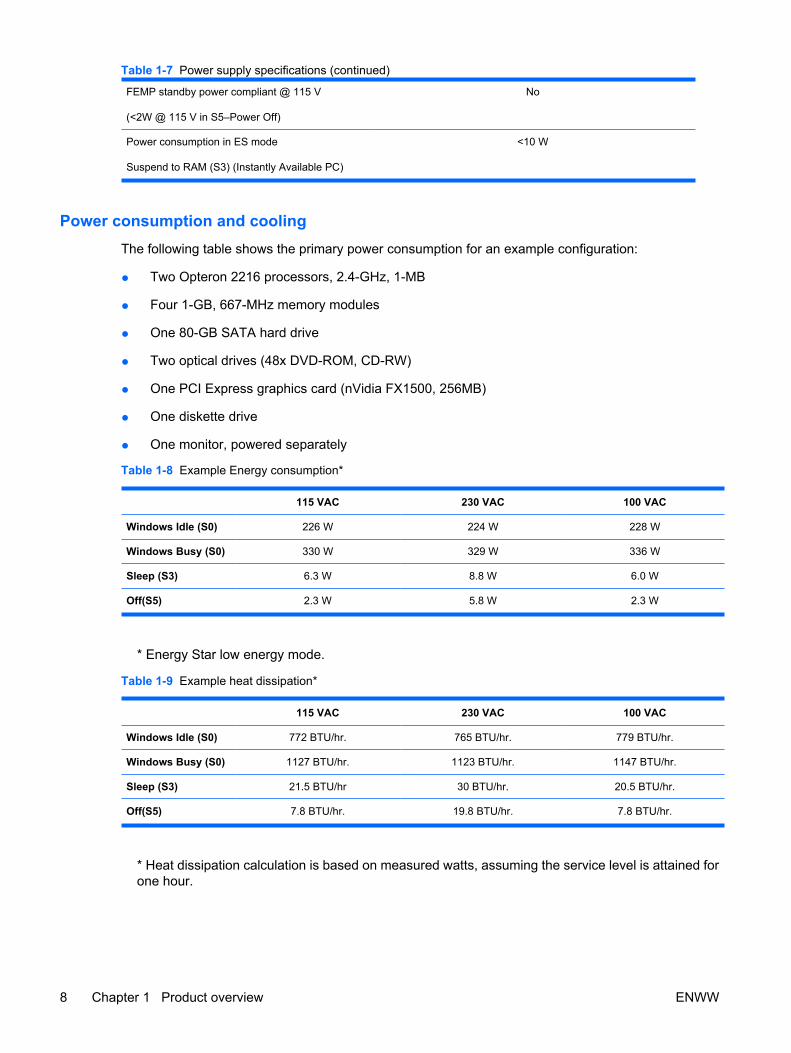
FEMP standby power compliant @ 115 V
(<2W @ 115 V in S5–Power Off)
No
Power consumption in ES mode
Suspend to RAM (S3) (Instantly Available PC)
<10 W
Power consumption and cooling The following table shows the primary power consumption for an example configuration:
● Two Opteron 2216 processors, 2.4-GHz, 1-MB
● Four 1-GB, 667-MHz memory modules
● One 80-GB SATA hard drive
● Two optical drives (48x DVD-ROM, CD-RW)
● One PCI Express graphics card (nVidia FX1500, 256MB)
● One diskette drive
● One monitor, powered separately
Table 1-8 Example Energy consumption*
115 VAC 230 VAC 100 VAC
Windows Idle (S0) 226 W 224 W 228 W
Windows Busy (S0) 330 W 329 W 336 W
Sleep (S3) 6.3 W 8.8 W 6.0 W
Off(S5) 2.3 W 5.8 W 2.3 W
* Energy Star low energy mode.
Table 1-9 Example heat dissipation*
115 VAC 230 VAC 100 VAC
Windows Idle (S0) 772 BTU/hr. 765 BTU/hr. 779 BTU/hr.
Windows Busy (S0) 1127 BTU/hr. 1123 BTU/hr. 1147 BTU/hr.
Sleep (S3) 21.5 BTU/hr 30 BTU/hr. 20.5 BTU/hr.
Off(S5) 7.8 BTU/hr. 19.8 BTU/hr. 7.8 BTU/hr.
* Heat dissipation calculation is based on measured watts, assuming the service level is attained forone hour.
Table 1-7 Power supply specifications (continued)
8 Chapter 1 Product overview ENWW

NOTE When you power down your workstation with the power button on the front panel, thepower consumption falls below 10 W. To reach zero power consumption, unplug the workstationfrom the power outlet or use a power strip with a switch.
For additional information on power-saving features, see your operating system documentation.
System fans and airflow The workstation includes one rear system fan, one memory fan, one processor (CPU) heatsink fan foreach processor, and one power supply fan, plus a front system fan.
Resetting the power supply If an overload triggers the power supply overload protection, all power is immediately shut off. To resetthe power supply unit:
1. Disconnect the power cord.
2. Determine what caused the overload and fix the problem.
3. Reconnect the power cord and reboot the workstation.
When you power down the workstation through the operating system, power consumption falls belowthe low power consumption rate but does not reach zero. This on/off feature extends the life of the powersupply.
Power cord requirementsThe power cord set (flexible cord or wall plug) received with this product meets the requirements for usein the country where you purchased the equipment.
If you must obtain a power cord for a different country, you should purchase a power cord that isapproved for use in that country.
The power cord must be rated for the product and for the voltage and current marked on the product’selectrical ratings label. The voltage and current rating of the cord should be greater than the voltage andcurrent rating marked on the product. The length of the cord must be between 6 feet (1.8 m) and 12 feet(3.6 m). If you have questions about the type of power cord to use, contact the HP authorized serviceprovider.
A power cord should be routed so that it is not likely to be walked on or pinched by items placed on itor against it. Particular attention should be paid to the plug, electrical outlet, and the point where thecord exits from the product.
NOTE A 15AMP-capable (minimum) power cord must be used in with a 110-V power source.A 10AMP-capable (minimum) power cord should be used with a 220-V power source.
Environmental specifications This section describes environmental specifications of your workstation.
Table 1-10 Environmental Specifications
Temperature (operating) 40° to 95° F (5° to 35° C)*
ENWW Product specifications 9

Temperature (non-operating) -40° to 140° F (-40° to 60° C)
Humidity (operating) 8% to 85% RH, non-condensing
Humidity (non-operating) 8% to 90% RH, non-condensing
Maximum Altitude (operating) 0 to 10,000 ft. (3,048 m)
Maximum Altitude (non-operating) 0 to 30,000 ft. (9,144 m)
Shock (operating) 1/2-sine: 40 G, 2–3 ms
Shock (non-operating) 1/2-sine: 160 cm/s, 2−3 ms, (approximately 100 G)
square: 605 cm/s, 30 G
NOTE Values represent individual shock events andare not indicative of repetitive shock events.
Vibration (operating) Operating random: 0.5 G (rms), 5−300 Hz
Vibration (non-operating) Random: 2.0 G (rms), 10−500 Hz
NOTE Values are not indicative of continuousvibration.
* Operating temperature is specified at 5° to 35° C from sea level to 5000 ft. with an altitude deratingof 1.0° C per every 300 m (1000 ft.) above 5000 ft. to a maximum of 3000 m (10,000 ft.), no directsustained sunlight. Maximum rate of change is 10° C/Hr. The upper limit may be limited by the typeand number of options installed.
PCI card slot power specificationTable 1-11 PCI and PCI Express slot power specifications
Slot# Slot Type Slot Power (Maximum)
1 PCI Express x16 (x8) 25 W*
2 PCI Express x16 graphics 150 W**
3 PCI 32 bit, 33 MHz 25 W*
4 PCI Express x16 (x8) 25 W*
5 PCI Express x16 graphics 150 W**
6 PCI-X 100 25 W*
7 PCI-X 100/133 25 W*
* In addition to these slot power specifications, the overall power consumption of the system (includingI/O cards, processor, and memory) must not exceed the maximum ratings of the system powersupply. See Power supply specifications on page 7 for details.** Includes 75 W maximum from the system board connector, and 75 W maximum from the auxiliarygraphics power connector.
Table 1-10 Environmental Specifications (continued)
10 Chapter 1 Product overview ENWW

NOTE If a graphics card requiring more than 75W is installed in Slot 2, HP recommends notusing slot 3, which is the PCI slot below the graphics slot. If a graphics card requiring more than75W is installed in slot 5, HP recommends not using slot 6, which is the PCI-X 100 slot below thegraphics slot. In addition to these slot power specifications, the overall power consumption of thesystem (including I/O cards, processors, memory, and drives) must not exceed the maximumratings of the system power supply. Also, there are broad restrictions on using dual 150Wgraphics cards.
For hardware specifications of other system components, such as graphics cards or optical drives, seethe website of the specific manufacturer.
ENWW Product specifications 11

Chipkill supportChipkill is a form of advanced Error Checking and Correcting (ECC) computer memory technology. TheHP xw9400 Workstation supports 128-bit Chipkill ECC memory functionality. Standard ECC functionalitydetects and corrects single bit data errors in memory systems. But Chipkill offers greater memory errorprotection by providing error correction for up to 4-bit errors within the same symbol (nibble boundary).Chipkill cannot correct any random four bits across 128 bits.
Chipkill on the xw9400 functions within these parameters:
● The workstation enables Chipkill functionality on paired ECC memory DIMMs only.
● The use of single memory DIMM—not supported on the xw9400 workstation—allows standardsingle bit ECC only.
● Chipkill can detect and correct up to four bit errors if the four bits are in the same symbol. That is,multiple bit errors in bits 0–3 or 4–7 of a byte can be detected and corrected. Multi-bit error thatoverlap or span symbol boundaries (bits 2–5 or 3–6, for example) cannot be corrected. For DIMMsthat are based on x4 parts, this means that a single DRAM chip can fail and the system will continueto operate. For x8 and x16 parts, a complete DRAM chip cannot fail, but symbol errors will becorrected as described.
12 Chapter 1 Product overview ENWW

Energy Star® The Energy Star program, a government-backed initiative, promotes energy efficiency by identifyingways to reduce energy consumption. Select HP workstations participate in the Energy Star program.
NOTE Energy Star is not supported on Linux-based workstations.
For those workstations that support Energy Star and have it enabled, the power management featuresare set as follows:
● The monitor goes into power savings mode after 20 minutes of inactivity.
● The system goes into standby mode after 20 minutes of inactivity
NOTE If you have to restore the operating system, reset the Energy Star settings (if applicable)after the restore.
To verify the factory default power settings for your product, select Start>Control Panel and double-click Power Options.
Energy Star complianceHP products purchased with the Energy Star configuration are compliant with U.S. EnvironmentalProtection Agency (EPA) Computers Program. The EPA Energy Star configuration does not implyendorsement by the EPA. As an Energy Star partner, HP offers products with the Energy Starconfiguration to meet the Energy Star guidelines for energy efficiency.
EPA created the Energy Star Computers Program to promote energy efficiency and reduce air pollutionthrough more energy-efficient equipment in homes, offices, and factories. HP products achieve thisresult by reducing the power consumption when not being used.
Energy Star on HP workstations uses Advanced Configuration and Power Interface (ACPI) powermanagement. The system can wake as a result of a user action (keyboard or mouse) or from the networkor a modem.
The Power Management feature, when used in conjunction with an Energy Star-compliant monitor, willsupport the power-down features of the monitor. The Power Management feature allows a monitor togo into low-power mode when the Energy Save timeout occurs.
NOTE Using the Energy Star Save Monitor feature with non-Energy Star-compliant monitorsmight cause video distortion when the Energy Save timeout occurs.
ENWW Energy Star® 13

14 Chapter 1 Product overview ENWW

2 Installing or restoring the operating system
This chapter describes the installation and restoration of the operating system.
● Installing the operating system and software on page 16
● HP software on page 18
● Restoring the operating system on page 19
● Protecting the software on page 22
If your workstation was shipped with a preinstalled operating system, it is configured automatically thefirst time your workstation is powered on. This process may take a few minutes.
Adding optional hardware devices to your workstation before the operating system successfully installscan cause errors and prevent the operating system from installing properly.
CAUTION After the automatic installation has begun, do not power off your workstation untilthis process completes. Powering off your workstation during the installation process mightdamage the software that runs the system.
ENWW 15

Installing the operating system and softwareThe following sections discuss operating system and HP software installation procedures.
Microsoft Windows XP Professional The first time you power on your workstation, you are prompted to select a language for the operatingsystem. After selecting the language, read and follow the instructions on the screen to complete theinstallation of the operating system. This process takes approximately 10 minutes, depending on thesystem hardware configuration. During the process, do not power off your workstation unless you aredirected to do so.
Installing or upgrading device driversTo install hardware devices, such as a printer, a display adapter, or network adapter after the operatingsystem installation is completed, the operating system needs access to the appropriate software driversfor the devices. Device drivers are usually provided on a CD supplied with the peripheral device.
Some existing peripheral devices might not have been shipped with drivers developed for Windows XP.To locate the most current device drivers, see http://www.hp.com/go/workstationsupport.
Linux-preinstalled workstationsIf you have a Linux-preinstalled workstation, follow the instructions in this section to set up your operatingsystem and software.
After the boot process completes, you can view additional HP Linux documentation by opening yourInternet browser (the browser is automatically set to use the local HP documentation page as its default).You can also access Linux Web links for Red Hat (Internet access required) by using your Internetbrowser.
For additional information about setting up Linux-preinstalled or Linux-enabled workstations, refer tothe HP User Manual for Linux at http://www.hp.com/support/linux_user_manual.
For more information about HP and Linux, see http://www.hp.com/linux.
Starting the Linux operating systemThe first time your workstation is booted, the Red Hat First Boot utility displays. This program enablesyou to enter your password, network, graphics, time, and keyboard settings for your workstation.
CAUTION After the automatic installation has begun, do not power down your workstation untilthe process is complete. Powering down your workstation during the installation process mightdamage the software that runs your workstation or prevent its proper installation.
When you enable the YPBind feature in the Network tab of the Linux Setup Tool, you might get a blankscreen for about 15–30 seconds after you have selected and saved all of your settings and exited theutility. This behavior is normal. The boot process continues its execution after the screen returns.
Upgrading device driversOnce your workstation is up and running, visit http://www.hp.com/go/workstationsupport to see if thereare newer device drivers available for your workstation and/or components.
16 Chapter 2 Installing or restoring the operating system ENWW

Linux-enabled workstationsLinux-enabled workstations are not preinstalled with Linux. They require the HP Installer Kit for Linuxand the purchase of a Red Hat box set. The Installer kit includes the HP CDs necessary to completethe installation of all versions of the Red Hat box set that have been verified to work on HP workstationhardware.
Verifying hardware compatibilityTo determine which Linux versions have been verified to work on HP workstation hardware:
1. Go to http://www.hp.com/support/linux_hardware_matrix.
2. Select your HP workstation model.
Installing the Linux operating systemTo install the Linux operating system on your Linux-enabled system, follow the instructions for Restoringthe Linux operating system on page 21 in this chapter.
For more information concerning the setup of Linux-preinstalled or Linux-enabled workstations, refer tothe HP User Manual for Linux located at http://www.hp.com/support/linux_user_manual.
For more information about HP and Linux, see http://www.hp.com/linux.
Red Hat ActivationAn activation card called Activate Your Subscription is shipped with your workstation. This card isnecessary to activate your Linux subscription with Red Hat Network. Until activation, your Red Hat Linuxis not fully enabled.
To activate Red Hat Linux, click the Activate Your Subscription icon on your desktop. This takes youto www.redhat.com/activate. Follow the instructions at this website to activate your subscription usingthe information on the card.
HP recommends that you activate your subscription as soon as you connect to the web.
NOTE Keep the Red Hat activation card with your workstation registration card for futurereference.
ENWW Installing the operating system and software 17

HP softwareThe following HP software may be installed on your workstation depending on the operating system andoptions:
● Computer Setup (F10) Utilities and diagnostic features
● HP Support Software including device drivers
● Security Management tools
● Software Support Management tools
Additional software is available for download:
● HP Client Manager Software is available at http://www.hp.com/go/easydeploy.
● System Software Manager is available at http://www.hp.com/go/ssm.
NOTE Additional HP software might be required in certain situations.
18 Chapter 2 Installing or restoring the operating system ENWW

Restoring the operating systemThis section describes how to restore the Windows and Linux operating systems.
Restoring the Windows operating systemYour workstation has a several methods to restore your Windows XP operating system to a near-factorystate, or to the state of the system at a predefined snapshot in time. Your system has a recovery partitionon the system hard drive that contains software and data required for the restore process as describedin the following sections.
NOTE If you received restore media with your system, use the media to restore your operatingsystem. Refer to the instructions on the media for restoring your operating system.
The RestorePlus! processThe Window operating system and device drivers (for devices shipped with the system) are reinstalledusing this process. Some application software may not be restored using the RestorePlus! process. Inthis case you must install the application software from the appropriate application CD. The RestorePlus!process can be executed from CD or from the recovery partition contained on your system hard drive.
CAUTION Backup your data before you attempt any operating system restore. All data on theWindows partition will be deleted when you restore using the RestorePlus! process. However,the recovery partition on the system drive and other partitions should not be affected.
Creating a RestorePlus! CD
You can create a set of the CDs from your system if you have a CD burner. When you first boot yoursystem, you will be prompted to make CDs for RestorePlus!, the Windows operating system, and asupplemental HP Backup and Recovery Manager CD. (There may be additional CDs you can createdepending on the options you purchased.) You also have the option to move images of the CDs toanother location, such as a network share, to be burned to CD at a later time or from another system.
Restoring from RestorePlus! CDs
The RestorePlus! process can be started by booting from the RestorePlus! CD.
Restoring from RestorePlus! on the Recovery Partition
Follow these steps to start the RestorePlus! process from the Emergency Recovery menu:
1. Boot the workstation.
2. Press the F11 key when prompted during the boot process to enter the Emergency Recovery menu.The F11 prompt appears briefly during the boot process.
3. Select Recover PC’s factory installed operating system, drivers, utilities, and applicationsfrom the Emergency Recovery menu.
NOTE Some applications may not be restored using this method.
ENWW Restoring the operating system 19

HP Backup and Recovery Manager restore pointsHP Backup and Recovery Manager is preinstalled on your workstation. This software allows you tobackup and restore your system and data. You will be prompted to make RestorePlus! CDs at the firstboot of the system. An Initial Restore Point (IRP) will be created automatically. This restore point is acomplete snapshot of the system partition at the time the IRP was created. The IRP is stored in therecovery partition on the system hard drive, but you can also burn the IRP to CDs, DVDs, or copy it toanother location. The restore point can be used to return the system partition back to the state the systemwas when captured.
Restoring from the HP Backup and Recovery Manager restore point CD/DVDs
The HP Backup and Recovery Manager (HPBR) restore point can be burned to CD or DVD and usedto restore the system. Typically you would used the CD/DVD set if the hard drive has been replaced orall partitions have been corrupted. Boot the system from the HPBR restore point CD/DVD and followthe online instructions.
Restoring from the HP Backup and Recovery Manager restore point on the Recovery Partition
The HP Backup and Recovery Manager (HPBR) Initial Restore Point is stored in the system recoverypartition and can be restored using the Emergency Recovery menu. Boot your system and press theF11 key when prompted to enter the Emergency Recovery menu. The F11 prompt appears briefly duringthe boot process. From the Emergency Recovery menu, choose Recover PC to a specific point intime and follow the instructions.
Reclaiming hard disk space from the recovery partitionThe recovery partition can be removed to reclaim the hard drive space. If the recovery partition isremoved, the F11 Emergency Recovery function is not available. The ability to recover the system fromdata on the recovery partition will be lost. Any RestorePlus! media contained in the recovery partitionwill be deleted. The ability to create the RestorePlus! CD set will be lost.
To free up disk space, you can remove just the recovery partition, or you can completely uninstall theHP Backup and Recovery Manager application.
● The recovery partition can be removed using Remove HP Recovery Partition in the HP Backup& Recovery program folder. The recovery partition is deleted, the user partition is extended toreclaim the unused hard drive space, and the F11 boot prompt is removed. The HP Backup andRecovery Manager application remains and can be used for data backup and restore.
● The HP Backup and Recovery Manager application can be uninstalled using the Windows ControlPanel>Add/Remove Programs utility. The application is uninstalled, the recovery partition isdeleted, the user partition is extended to reclaim the unused space, and the F11 boot prompt isremoved. Emergency recovery as well as data backup and recovery is not possible after theapplication is uninstalled.
CAUTION Deleting the recovery partition or uninstalling the HP Backup and Recovery Managerapplication reduces or eliminates the ability to recover the system.
Ordering backup softwareIf you are unable to create system recovery CDs or DVDs, the HP Restore Plus CD set can be obtainedthrough product support on http://www.hp.com/support.
20 Chapter 2 Installing or restoring the operating system ENWW

NOTE Before calling HP to order the software, be sure to have the serial number of yourworkstation available. See Serial number and COA label location on page 5 for details.
Restoring the Linux operating system
NOTE To restore the Linux operating system, the HP Driver CD and Red Hat box set arerequired. Download the latest HP Driver CD to get any new enhancements.
For preloaded Linux systems, an icon called Red Hat ISO's is available on the desktop. Click this iconto go to the /iso directory. This directory contains the binary and source ISO files. This directory alsocontains the driver CD ISO which is the same as the CD that is shipped with the workstation. Follow theinstructions in the Readme file in the /iso directory to burn the ISOs to CD.
HP recommends that you burn the ISOs to CD so you have a backup.
NOTE Linux does not support mixed drive types for a manufacturing preload. However, Linuxsupports mixed drives and you may restore the operating system with mixed drives from theRHEL box set.
Downloading the latest HP driver CD contents
See http://www.hp.com and select Software and Drive Downloads. Find your workstation andoperating system. Select your driver CD under Software, and follow the directions under ReleaseNotes.
Installing the operating system with the HP driver CD contents
1. Boot your workstation from the Red Hat box set Binary CD 1.
2. Insert the Linux operating system CDs from the Red Hat box set as prompted.
3. Continue following the prompts until the operating system is successfully installed.
4. Configure the X server to start on reboot.
5. Reboot your workstation.
6. Follow the prompts to set up your system with the Red Hat First Boot utility.
7. When prompted in First Boot to add additional CDs, insert the HP Driver CD into the CD-ROM trayof your workstation.
8. Click Install next to “Additional CDs.” The HP Driver CD window opens.
9. Click Press to begin install.
When the install is done, you will have two options— Reboot now... on the left side and Press tocontinue, reboot later... on the right side.
10. Click Reboot now...
ENWW Restoring the operating system 21

Protecting the softwareTo protect software from loss or damage, keep a backup copy of all system software, applications, andrelated files stored on the hard drive. See the operating system or backup utility documentation forinstructions on making backup copies of data files.
22 Chapter 2 Installing or restoring the operating system ENWW

3 System management
This section describes the various tools and utilities that allow for the system management of theworkstation.
● Computer Setup (F10) Utility on page 24
● Desktop management on page 34
ENWW 23
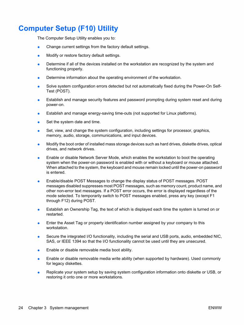
Computer Setup (F10) UtilityThe Computer Setup Utility enables you to:
● Change current settings from the factory default settings.
● Modify or restore factory default settings.
● Determine if all of the devices installed on the workstation are recognized by the system andfunctioning properly.
● Determine information about the operating environment of the workstation.
● Solve system configuration errors detected but not automatically fixed during the Power-On Self-Test (POST).
● Establish and manage security features and password prompting during system reset and duringpower-on.
● Establish and manage energy-saving time-outs (not supported for Linux platforms).
● Set the system date and time.
● Set, view, and change the system configuration, including settings for processor, graphics,memory, audio, storage, communications, and input devices.
● Modify the boot order of installed mass storage devices such as hard drives, diskette drives, opticaldrives, and network drives.
● Enable or disable Network Server Mode, which enables the workstation to boot the operatingsystem when the power-on password is enabled with or without a keyboard or mouse attached.When attached to the system, the keyboard and mouse remain locked until the power-on passwordis entered.
● Enable/disable POST Messages to change the display status of POST messages. POSTmessages disabled suppresses most POST messages, such as memory count, product name, andother non-error text messages. If a POST error occurs, the error is displayed regardless of themode selected. To temporarily switch to POST messages enabled, press any key (except F1through F12) during POST.
● Establish an Ownership Tag, the text of which is displayed each time the system is turned on orrestarted.
● Enter the Asset Tag or property identification number assigned by your company to thisworkstation.
● Secure the integrated I/O functionality, including the serial and USB ports, audio, embedded NIC,SAS, or IEEE 1394 so that the I/O functionality cannot be used until they are unsecured.
● Enable or disable removable media boot ability.
● Enable or disable removable media write ability (when supported by hardware). Used commonlyfor legacy diskettes.
● Replicate your system setup by saving system configuration information onto diskette or USB, orrestoring it onto one or more workstations.
24 Chapter 3 System management ENWW

BIOS ROMThe BIOS of the computer is a collection of programs stored as firmware in ROM. The BIOS ROMincludes such functions as POST, PCI device initialization, Plug 'n' Play support, power managementactivities, and the Computer Setup Utility. BIOS supports the following systems and specifications:
● Dual AMD Opteron 2xxx series processors
● Up to DDR2-667 memory
● HyperTransport setup and initialization
● Chipset (includes NVIDIA nForce Professional 3600 and 3050 with NEC µPD720404 PCIe to PCI-X bridge)
● ACPI 1.0b with ACPI 2.0 extensions for 64-bit support, according to Microsoft Logo Requirements.S1, S3, S4, and S5 with Remote Power On by way of LAN wake packet.
● SMBIOS Spec 2.5 implementation and field definitions that accurately represent hardwareconfigurations and OEM ID
● BBS 1.01
● DOS and Windows based BIOS flash tools
● Microsoft SDG 3.0 compliant as applicable
● PMM 1.01 as applicable
● MPS 1.4 as applicable
● PXE 2.1
● USB 1.1/USB 2.0
● PCI 2.2 or later
● “El Torito” Bootable CD 1.0
The BIOS ROM is a 1-MB FLASH unit. The runtime portion of the BIOS resides in a 96-KB block fromE8000h to FFFFFh (approximately). ACPI code and data take about 128 KB below TOLM (top of lowmemory, the last RAM address below 4 GB).
Using Computer Setup (F10) Utility You can call up the Computer Setup Utility during workstation restart or power on. To access theComputer Setup Utility menu:
1. Power on or restart the workstation.
2. Press the F10 key as soon as your display is active and the message Setup appears in the lowerright corner of the screen.
NOTE If you miss the opportunity to press F10, restart the workstation and press F10again. Or, you can press Ctrl+Alt+Delete prior to boot .
3. At first boot, select your language from the list, and press the Enter key. In the Computer SetupUtility menu, five headings are displayed: File, Storage, Security, Advanced, and I/O.
ENWW Computer Setup (F10) Utility 25

4. Use the left and right arrow keys to select the appropriate heading. Use the up and down arrowkeys to select the option you want, and press Enter.
5. To apply and save changes, select File>Save Changes and Exit.
● If you have made changes that you do not want applied, select File>Ignore Changes andExit.
● To reset to factory settings, select File>Default Setup>Restore Factory Settings asDefault. Press F10 to accept the changes. Click File>Apply Defaults and Exit. This optionrestores the original factory system defaults.
CAUTION Do not turn the workstation power off while the ROM is saving your Computer SetupUtility changes because the CMOS could become corrupted. After you exit the F10 Setup screen,it is safe to remove all power from the workstation.
Computer Setup (F10) Utility menu
NOTE The following content is subject to change with new BIOS releases, so your menu maybe different than shown in Table 1–1.
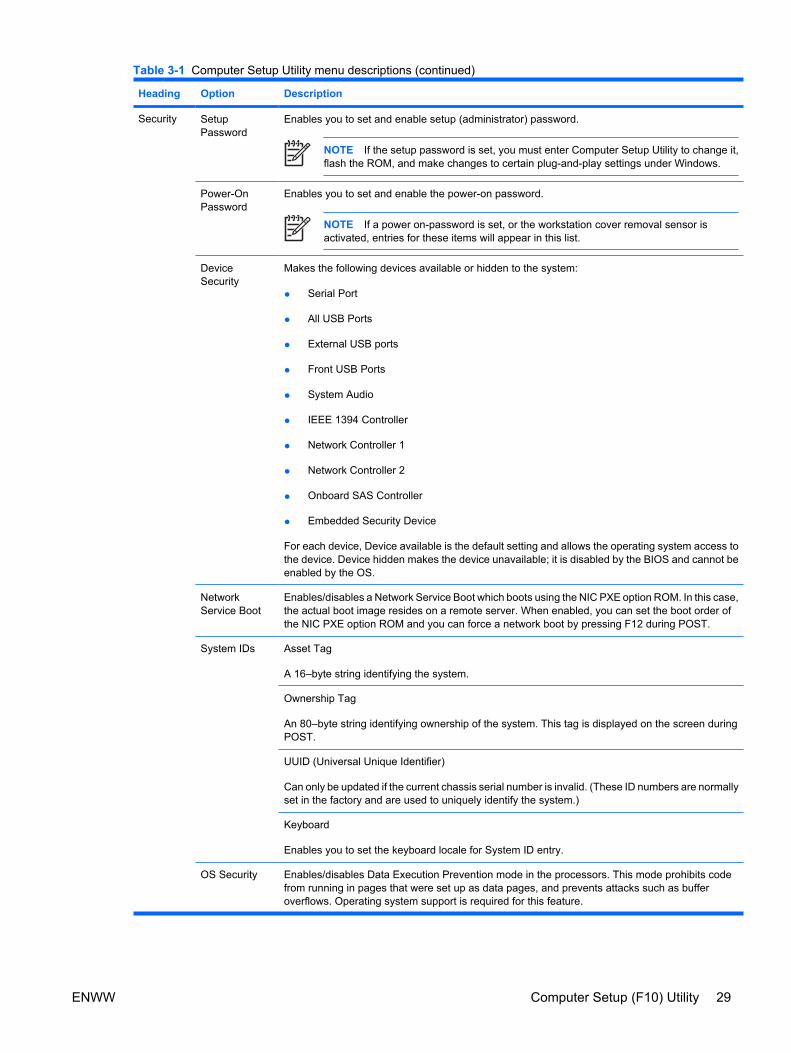
Table 3-1 Computer Setup Utility menu descriptions
Heading Option Description
File SystemInformation
Lists product name, SKU number, processor type/speed/stepping, cache size (L1/L2), memorytype and size, integrated Media Access Control (MAC) IDs for Network Interface, system BIOStype, chassis serial number, and asset tracking number.
About Displays copyright information.
SystemTemperatures
Displays temperature graph.
Set Time andDate
Enables you to set system time and date.
ReplicatedSetup
Save to Removable Media
Saves the current F10 Setup configuration to a text file called cpqsetup.txt.
Restore from Removable Media
Restores previous F10 Setup configuration from a text file called cpqsetup.txt.
Default Setup Save Current Settings as Default
Stores the current F10 Setup configuration as the default.
Restore Factory Settings as Default
Restores the original factory settings to the F10 Setup configuration information as the default.
Apply Defaultsand Exit
Saves the selected default settings (previously-saved user or factory settings) and exits theComputer Setup Utility.
IgnoreChanges andExit
Exits the Computer Setup Utility without applying or saving any changes.
Save Changesand Exit
Saves changes to system configuration and exits the Computer Setup Utility.
26 Chapter 3 System management ENWW

Heading Option Description
Storage DeviceConfiguration
Lists all installed non-SAS and non-SATA storage devices.
When a device is selected, detailed information and options are displayed.
CD-ROM
Identifies the optical drives on the system.
Diskette (for legacy diskette drives only)
Identifies the highest capacity media type accepted by the diskette drive. Options are 3.5" 1.44MB, 5.25" 1.2 MB, and Not Installed.
Default Values
Enables you to set the default values for IDE and SATA devices such as the following:
● Multisector Transfers (IDE devices only)–Specifies how many sectors are transferred permulti-sector Programmed Input/Output (PIO) operation. Options (subject to devicecapabilities) are Disabled, 8, and 16.
● Transfer Mode (IDE devices only)–Specifies the active data transfer mode. Options (subjectto device capabilities) are PIO 0, Max PIO, Enhanced DMA, Ultra DMA 0, and Max UDMA.
● Translation Mode (IDE/SATA disks only)–Enables you to select the translation mode to beused for the device, which enables the BIOS to access disks partitioned and formatted onother systems and may be necessary for users of older versions of UNIX (for example, SCOUNIX version 3.2). Options are Bit-Shift, LBA Assisted, Off, User, and Automatic.
NOTE The Automatic option allows BIOS to automatically determine the translationmode used to configure a previously-formatted IDE, SATA, or USB mass storagedevice. Hence, you do not have to know how the mass storage device was previouslyformatted.
Ordinarily, the translation mode selected automatically by the BIOS should not be changed.If the selected translation mode is not compatible with the translation mode that was activewhen the disk was partitioned and formatted, the data on the disk will be inaccessible.
Table 3-1 Computer Setup Utility menu descriptions (continued)
ENWW Computer Setup (F10) Utility 27

Heading Option Description
StorageOptions
Removable Media Boot
Enables/disables ability to boot the system from removable media.
Legacy Diskette Write
Enables/disables ability to write data to legacy media.
BIOS DMA Data Transfers
Enables/disables DMA transfers for IDE and SATA devices when possible during POST to increasetransfer speed.
SATA Controller #0
Enables/disables SATA controller 0.
SATA Controller #1
Enables/disables SATA controller 1.
SATA Controller #2
Enables/disables SATA controller 2.
IDE Controller
Enables/disables IDE controller.
Boot Order Enables you to configure the boot, diskette drive, and hard drive orders by physically reorderingthe menu entries. Each device on the list can be individually excluded from or included forconsideration as a bootable operating system source. Boot Order presents these selections:
● Optical drive
● Diskette drive
● USB device
● Hard drive
● Network controllers (2)
Boot devices can be disabled from participating in the boot order process. Boot order changes arestored when the F10 Setup changes are confirmed by selecting File>Save Changes and Exit.
NOTE MS-DOS drive lettering assignments might not apply after a non-MS-DOSoperating system has started.
Shortcut to Temporarily Override Boot Order
To boot one time from a device other than the default device specified in Boot Order, restart theworkstation and press the F9 key when the F9=Boot Menu message appears on the screen. AfterPOST is completed, a list of bootable devices is displayed. Use the arrow keys to select thepreferred bootable device and press Enter. The workstation then boots from the selected devicefor this one time.
Table 3-1 Computer Setup Utility menu descriptions (continued)
28 Chapter 3 System management ENWW
Heading Option Description
Security SetupPassword
Enables you to set and enable setup (administrator) password.
NOTE If the setup password is set, you must enter Computer Setup Utility to change it,flash the ROM, and make changes to certain plug-and-play settings under Windows.
Power-OnPassword
Enables you to set and enable the power-on password.
NOTE If a power on-password is set, or the workstation cover removal sensor isactivated, entries for these items will appear in this list.
DeviceSecurity
Makes the following devices available or hidden to the system:
● Serial Port
● All USB Ports
● External USB ports
● Front USB Ports
● System Audio
● IEEE 1394 Controller
● Network Controller 1
● Network Controller 2
● Onboard SAS Controller
● Embedded Security Device
For each device, Device available is the default setting and allows the operating system access tothe device. Device hidden makes the device unavailable; it is disabled by the BIOS and cannot beenabled by the OS.
NetworkService Boot
Enables/disables a Network Service Boot which boots using the NIC PXE option ROM. In this case,the actual boot image resides on a remote server. When enabled, you can set the boot order ofthe NIC PXE option ROM and you can force a network boot by pressing F12 during POST.
System IDs Asset Tag
A 16–byte string identifying the system.
Ownership Tag
An 80–byte string identifying ownership of the system. This tag is displayed on the screen duringPOST.
UUID (Universal Unique Identifier)
Can only be updated if the current chassis serial number is invalid. (These ID numbers are normallyset in the factory and are used to uniquely identify the system.)
Keyboard
Enables you to set the keyboard locale for System ID entry.
OS Security Enables/disables Data Execution Prevention mode in the processors. This mode prohibits codefrom running in pages that were set up as data pages, and prevents attacks such as bufferoverflows. Operating system support is required for this feature.
Table 3-1 Computer Setup Utility menu descriptions (continued)
ENWW Computer Setup (F10) Utility 29

Heading Option Description
Advanced**
Power-OnOptions
POST Mode (QuickBoot, FullBoot, or FullBoot every 1–30 days)
Quick boot is faster by skipping some steps such as the full memory test.
POST Messages (Enable/Disable).
When enabled, POST displays non-error messages to the screen.
F9 Prompt (Displayed/Hidden)
Displays F9=Boot Menu during POST. Hiding this feature prevents the text from being displayed,but pressing F9 still calls up the boot menu.
F10 prompt (Displayed/Hidden)
Displays F10=Setup during POST. Hiding this feature prevents the text from being displayed butpressing F10 still accesses the Setup screen.
F12 prompt (Displayed/Hidden)
Displays F12=Network Service Boot during POST. Hiding this feature prevents the text frombeing displayed, but pressing F12 still forces the system to attempt booting from the network.
Option ROM* Prompt (Enable/Disable)
When enabled, causes the system to display a message before loading options ROMs.
Remote Wakeup Boot Source
Enables you to specify which boot device to use after a remote wake event.
After Power Loss (Off/On/Previous State)
In the event of an AC power loss, determines system behavior when power is restored. Optionsare Off (stay off), On (turn on immediately), and Previous State (if the computer was on whenpower was lost, power on immediately; if it was off, stay off).
POST Delay (in seconds) (None, 5, 10, 15, 20)
Specifies a delay during POST. This setting may be necessary for certain add-in peripherals thatrespond slowly or violate specifications. For instance, disk drives should spin up within 15 seconds,but some older drives might take longer.
Setup Browse Mode (Enable/Disable)
Enables viewing Setup Options without entering Setup password. Enable allows you to view Setupin read-only mode if you do not enter the Setup password. Disable blocks Setup entirely if you donot enter the Setup password. This option is only valid if a Setup password is set.
Thermal Fan Idle Mode
This setting changes the minimum fan speed. The fans are still automatically controlled.
The internal fans of the system are controlled automatically to guarantee proper operation of anyconfiguration shipped from the factory. However, some customers with cards and configurationswith special thermal/cooling needs may need to increase the minimum spinning speed of the fansin the system. They can do so by using this menu and selecting a higher minimal fan speed.
BIOS Power-On
Enables you to disable or specify a day and time for BIOS power-on.
OS PowerManagement
ACPI S3 Support (Enable/Disable)
Enables/disables ACPI S3 suspend-to-RAM (Standby) from OS.
ACPI S3 Hard Disk Reset (Enable/Disable)
Table 3-1 Computer Setup Utility menu descriptions (continued)
30 Chapter 3 System management ENWW

Heading Option Description
When awakening from the ACPI S3 state, reset IDE hard drive before returning to the OS.
ACPI S3 PS2 Mouse Wake Up (Enable/Disable)
Allow the mouse to awaken the system from the ACPI S3 state.
USB Wake on Device Insertion (Enable/Disable)
Awaken the system from ACPI S3 state on USB device insertion.
ExecuteMemory Test
System re-boots and executes the memory test.
Chipset/Memory
ECC Support (Enable/Disable)
Enables/disables memory Error Correcting Code (ECC).
Memory Scrubbing (Enable/Disable)
Enables/disables memory ECC scrubbing. If ECC Support is enabled, the scrubbing feature walksthrough memory in the background to avoid accumulation of ECC errors in memory. Upon detectionof an ECC error, either during the scrubbing walk-through or during normal processor-to-memoryoperation, the scrubbing mechanism corrects the data and writes it back into the correspondingmemory DIMM module.
Memory Node Interleave (Enable/Disable)
This option is valid for dual-processor systems only.
If enabled, BIOS interleaves the memory on CPU0 and CPU1 together. This option requires thetotal memory installed on CPU0 (slots 1a/1b/3a/3b) and on CPU1 (slots 2a/2b/4a/4b) to be thesame.
If disabled, BIOS maps the memory connected to CPU0, then the memory connected to CPU1.The system is then effectively in NUMA mode.
PCI SERR# Generation (Enable/Disable)
Disables PCI SERR# generation for ill-behaved PCI add-in cards that can generate spuriousSERRs.
NET Watchdog Timer (Enable/Disable)
Enables/disables the watchdog timer.
ACPI Bus Segmentation (Enable/Disable)
Enables/disables PCI bus segmentation. Disabling this option may prevent installation issues withsome Linux implementations.
HPET (Enable/Disable)
Enables/disables the High Precision Event Timer. This feature must be enabled to use low powersettings (PowerNow!). Some Linux implementations may require disabling this feature.
Table 3-1 Computer Setup Utility menu descriptions (continued)
ENWW Computer Setup (F10) Utility 31

Heading Option Description
I/O** APIC Interrupts APIC
Allow manual configuration of system IRQs.
For more details on using this feature and on maximizing interrupt performance, refer to theOptimizing APIC Interrupt Assignments on the xw9400 white paper available athttp://tclperf.fc.hp.com/performance_briefs/index.htm.
OnboardDevices
Disable or set IRQ, DMA, and I/O Range values for legacy devices.
PCI Devices Disable or select IRQ values for PCI devices.
Device Options NIC PXE Option ROM Download (Enable/Disable)
Disable means you cannot boot from this device, but more option ROM space is available for otherdevices.
Onboard SAS Option ROM Download (Enable/Disable)
Disable means you cannot boot from SAS drives, but more option ROM space is available forother devices.
SATA Option ROM Download (Enable/Disable)
Enables or disables downloading embedded SATA option ROM. Disable means you cannot bootfrom SATA devices, but more option ROM space is available for other devices.
SATA RAID (Enable/Disable)
Enables or disables SATA drives for a RAID. If disabled, a single line is displayed. If enabled, themenu expands to allow enabling/disabling each SATA port.
Num Lock State at Power-On (Off/On)
Sets the keyboard Num Lock state after POST. The Operating System can change this state, also.
S5 Wake on LAN (Enable/Disable)
Allows the network to wake the system from shutdown (ACPI S5). When set to Disable, systempower consumption is reduced to match Federal Energy Management Program (FEMP) guidelines.
Unique Sleep State Blink Rates (Enable/Disable)
Assigns different LED blink patterns for S1 and S3. (The system LED is off for S4 and S5.)
Monitor Tracking (Enable/Disable)
Enabling this option allows the ROM to save the monitor asset tracking information such as theserial number and model.
Slot Options Modifies options for:
● Slot 1—PCI Express x8
● Slot 2—PCI Express x16 graphics
● Slot 3—PCI 32 bit, 33 MHz
● Slot 4—PCI Express x16 (x8)
● Slot 5—PCI Express x16 graphics
● Slot 6—PCI-X 100
● Slot 7—PCI-X 100/133
Table 3-1 Computer Setup Utility menu descriptions (continued)
32 Chapter 3 System management ENWW

Heading Option Description
For PCI Express slots, the available option is Option ROM Download.
For PCI and PCI-X slots, the available options are Option ROM Download and Latency Timer.
* Available on select models.
** These options should be used by advanced users only.
Table 3-1 Computer Setup Utility menu descriptions (continued)
ENWW Computer Setup (F10) Utility 33
Desktop managementHP Client Management Solutions (available for download from http://www.hp.com/go/easydeploy)provides standards-based solutions for managing and controlling workstations in a networkedenvironment. This section summarizes the capabilities and features of desktop management keycomponents:
● Initial configuration and deployment on page 34
● Remote system installation on page 34
● Managing and updating software on page 35
● ROM flash on page 37
● Asset tracking and security on page 41
● Fault notification and recovery on page 47
NOTE Support for specific features described in this guide might vary by model or softwareversion.
Initial configuration and deploymentThe workstation comes with a preinstalled system software image. After a brief software unbundlingprocess, the workstation is ready to use.
You might prefer to replace the preinstalled software image with a customized set of system andapplication software. There are several methods for deploying a customized software image, including:
● Installing additional software applications after unbundling the preinstalled software image.
● Using software deployment tools, such as Altiris® Deployment Solutions™, to replace thepreinstalled software with a customized software image.
● Using a disk cloning process to copy the contents from one hard drive to another.
The best deployment method depends on your information technology environment and processes. ThePC Deployment section of the HP Lifecycle Solutions website (http://whp-sp-orig.extweb.hp.com/country/us/en/solutions.html) provides information to help you select the best deployment method.
The Restore Plus! CD, ROM-based setup, and ACPI hardware provide further assistance with recoveryof system software, configuration management and troubleshooting, and power management.
Remote system installationRemote System Installation enables you to start and set up your system using the software andconfiguration information located on a network server. This feature is usually used as a system setupand configuration tool, and can be used for the following tasks:
● Deploying a software image on one or more new PCs
● Formatting a hard drive
● Installing application software or drivers
● Updating the operating system, application software, or drivers
34 Chapter 3 System management ENWW

To initiate Remote System Installation, press F12 when F12=Network Service Boot appears in thelower-right corner of the HP logo screen. Follow the on-screen instructions to continue the process.The default boot order is a BIOS configuration setting that can be changed to always attempt to PXEboot.
HP and Altiris have partnered to provide tools designed to make the task of corporate PC deploymentand management easier and less time-consuming, ultimately lowering the total cost of ownership andmaking HP PCs the most manageable client PCs in the enterprise environment.
Managing and updating softwareHP provides several tools for managing and updating software on desktops and workstations—HP ClientManager Software, Altiris Client Management Solutions, System Software Manager, Proactive ChangeNotification, and Subscriber’s Choice.
HP Client Manager softwareHP Client Manager Software (HP CMS) assists you in managing the hardware aspects of your clientworkstations with features that include:
● Detailed views of hardware inventory for asset management
● PC health check monitoring and diagnostics
● Proactive notification of changes in the hardware environment
● Web-accessible reporting of business-critical details such as machines with thermal warnings,memory alerts, and more
● Remote updating of system software such as device drivers and ROM BIOS
● Remote changing of boot order
● Configuring the system BIOS settings
For more information on the HP Client Manager, see http://h18000.www1.hp.com/im/prodinfo.html.
Altiris Client Management solutionsHP and Altiris have partnered to provide comprehensive, tightly integrated systems managementsolutions to reduce the cost of owning HP client PCs. HP Client Manager Software is the foundation foradditional Altiris Client Management Solutions that address:
● Inventory and asset management
● Software license compliance
● PC tracking and reporting
● Lease contract and fixed asset tracking
● Deployment and migration
● System deployment
● Personality migrations
ENWW Desktop management 35
● Help desk and problem resolution
● Managing help desk tickets
● Remote troubleshooting
● Remote problem resolution
● Client disaster recovery
● Software and operations management
● Ongoing desktop management
● HP system software deployment
● Application self-healing
See http://h18000.www1.hp.com/im/prodinfo.html for more information about:
● How HP Client Manager Software works
● Which solutions are compatible with your operating system
● How to download a fully-functional, 30-day evaluation version of the Altiris solutions
System Software ManagerSystem Software Manager (SSM) is a utility that enables you to update system-level software on multiplesystems simultaneously. When executed on a PC client system, SSM detects both hardware andsoftware versions and then updates the appropriate software from a central repository, also known asa file store. Driver versions that are supported by SSM are denoted with a special icon on the software,the driver download website, and the Support Software CD. To download the utility or to obtain moreinformation on SSM, see http://www.hp.com/go/ssm.
Proactive Change NotificationThe Proactive Change Notification program uses the Subscriber's Choice website to proactively andautomatically send you:
● Proactive Change Notification (PCN) e-mails informing you of hardware and software changes tomost commercial workstations and servers, up to 60 days in advance.
● E-mails containing Customer Bulletins, customer advisories, customer notes, security bulletins,and driver alerts for most commercial workstations and servers.
You create your own profile to ensure that you only receive the information relevant to a specific ITenvironment. To learn more about the Proactive Change Notification program and create a customprofile, see http://www.hp.com/go/pcn.
Subscriber’s ChoiceSubscriber’s Choice is a client-based service from HP. Based on your profile, HP supplies you withpersonalized product tips, feature articles, and driver and support alerts and notifications. Subscriber’sChoice Driver and Support Alerts/Notifications deliver e-mails notifying you that the information yousubscribed to in your profile is available for review and retrieval. To learn more about Subscriber’sChoice and create a custom profile, see http://www.hp.com/go/pcn.
36 Chapter 3 System management ENWW

ROM flashThe workstation comes with a programmable flash ROM. By establishing a setup password in theComputer Setup Utility, you can protect the ROM from being unintentionally updated or overwritten,which is important to ensure the operating integrity of the workstation. Should you need or want toupgrade the ROM, you can:
● Order an upgraded ROMPaq diskette from HP.
● Download the latest ROMPaq images from HP driver and support page, http://www.hp.com/support/files.
NOTE For maximum ROM protection, be sure to establish a setup password. The setuppassword prevents unauthorized ROM upgrades. System Software Manager enables you to setthe setup password on one or more PCs simultaneously. For more information, seehttp://www.hp.com/go/ssm.
Remote ROM flashRemote ROM Flash enables you to safely upgrade the ROM on remote HP workstations directly fromthe centralized network management console. Performing this task remotely on multiple workstationsand personal computers results in a consistent deployment of and greater control over HP ROM imagesover the network. It also results in greater productivity and lower total cost of ownership.
The workstation must be powered on to use Remote ROM Flash.
For more information on Remote ROM Flash, see the HP Client Manager Software or System SoftwareManager at http://h18000.www1.hp.com/im/prodinfo.html.
HPQFlashThe HPQFlash utility is used to locally update or restore the system ROM on individual workstationsthrough a Windows operating system.
For more information on HPQFlash, see http://www.hp.com/support/files and enter the name of yourworkstation when prompted.
FailSafe Boot Block ROMThe FailSafe Boot Block ROM allows for system recovery in the unlikely event of a ROM flash failure,for example, if a power failure occurs during a ROM upgrade. The Boot Block is a protected section ofthe ROM that checks for a valid system ROM flash when the system is powered on.
NOTE System recovery can use a removable medium such as a diskette, CD, or USB.
● If the system ROM is valid, the system starts normally.
● If the system ROM fails the validation check, the FailSafe Boot Block ROM provides enough supportto start the system from a ROMPaq removable medium which will program the system ROM witha valid image.
NOTE Workstation models that support recovery from a ROMPaq CD provide ISO ROMPaqimages in the downloadable ROM SoftPaq.
ENWW Desktop management 37

When the Boot Block detects an invalid system ROM, the System Power LED blinks red eight times,once every second, followed by a two-second pause. Also, you will hear eight beeps that correspondto the blinks. A Boot Block recovery mode message is displayed on the screen (some models).
To recover the system after it enters Boot Block recovery mode:
1. If a removable medium is loaded in the workstation, remove it and power down the workstation.
2. Insert the appropriate ROMPaq removable medium in the workstation.
3. Power on the workstation.
If no ROMPaq removable medium is found, you are prompted to insert one and restart theworkstation.
If a setup password has been established, the Caps Lock light illuminates and you are promptedto enter the password.
4. Enter the setup password.
If the system successfully starts from the removable medium and successfully reprograms theROM, the three keyboard lights illuminate.
5. Remove the removable medium and restart the system.
The following table lists the various keyboard light combinations used by the Boot Block ROM (when aPS/2 keyboard is attached to the workstation) and explains the meaning and action associated witheach combination.
Table 3-2 PS/2 keyboard light combinations used by Boot Block ROM
Light State Description
FailSafe BootBlock Mode
Keyboard LED Activity State/Message
Num Lock On ROMPaq diskette or ROMPaq CD not present, is bad, or drive not ready
Caps Lock On Enter password
Num, Caps,Scroll Lock
Blink On in sequence,one at a time—N,C, SL
Keyboard locked in network mode
Num, Caps,Scroll Lock
On Boot Block ROM Flash successful.
Diagnostic lights do not flash on USB keyboards.
Replicating the setupThe following procedures enable you to easily copy one setup configuration to other workstations of thesame model to provide faster, more consistent configuration of multiple workstations.
NOTE Setup configuration procedures require a diskette or a USB such as an HP DriveKey.
To collect and replicate BIOS settings on multiple computers, use System Software Manager orHP Client Manager Software. For more information, see http://www.hp.com/go/easydeploy.
38 Chapter 3 System management ENWW

Copying to a single workstation
CAUTION A setup configuration is model-specific. File system corruption can result if thesource and target workstations are not the same model. For example, do not copy the setupconfiguration from an HP xw6200 Workstation to an HP xw9400 Workstation.
1. Select a setup configuration to copy, then shut down the workstation.
2. Reboot the workstation.
3. As soon as the screen illuminates, press and hold the F10 key until you enter the Computer SetupUtility. Press Enter to bypass the title screen, if necessary.
NOTE If you do not press the F10 key at the appropriate time, you must restart theworkstation and press and hold the F10 key again to access the utility.
If you are using a PS/2 keyboard, disregard the keyboard error message that might appear.
4. Insert the configuration diskette or USB.
5. Click File>Replicated Setup>Save to Removable Media. Follow the instructions on the screento create the configuration diskette or USB.
6. Power off the workstation to be configured and insert the diskette or USB.
7. Power on the workstation to be configured.
8. As soon as the screen illuminates, press and hold the F10 key until you enter the Computer SetupUtility. Press Enter to bypass the title screen, if necessary.
9. Click File>Replicated Setup>Restore from Removable Media, and follow the instructions on thescreen.
10. Restart the workstation when the configuration is complete.
Copying to multiple workstations
CAUTION A setup configuration is model-specific. File system corruption can result if thesource and target workstations are not the same model. For example, do not copy the setupconfiguration from an HP xw6200 Workstation to an HP xw9400 Workstation.
This method takes a little longer to prepare the configuration diskette or USB, but copying theconfiguration to target workstations is significantly faster.
NOTE A bootable diskette or USB is required for this procedure. If Windows XP is not availableto create a bootable diskette or USB, use the method for copying to a single workstation instead(see Copying to a single workstation on page 39).
1. Create a bootable diskette or USB.
2. Select a setup configuration to copy, then shut down the workstation.
3. Power on the workstation.
4. As soon as the screen illuminates, press and hold the F10 key until you enter the Computer SetupUtility. Press Enter to bypass the title screen, if necessary.
ENWW Desktop management 39
NOTE If you do not press the F10 key at the appropriate time, you must restart theworkstation and press and hold the F10 key again to access the utility.
If you are using a PS/2 keyboard, disregard the keyboard error message that might appear.
5. Insert the diskette or USB.
6. Click File>Replicated Setup>Save to Removable Media. Follow the instructions on the screento create the configuration diskette or USB.
7. Download a BIOS utility for replicating setup (repset.exe), and copy it onto the configuration disketteor USB. To obtain this utility, go to http://www.hp.com/support/files and enter the model number ofthe workstation.
8. On the configuration diskette or USB, create an autoexec.bat file containing the followingcommand: repset.exe cpqsetup.txt.
9. Power off the workstation to be configured. Insert the configuration diskette or USB and power onthe workstation. The configuration utility runs automatically.
10. Restart the workstation when the configuration is complete.
Dual-state power buttonWith ACPI enabled, the power button can function either as an on/off switch or as a sleep button. Thefeature does not completely remove the power, but instead causes the workstation to enter a low-powerstandby state. This feature enables you to power off without closing applications and to return to thesame operational state without any data loss.
To change the power button configuration:
1. Click Start, and select Control Panel>Power Options.
2. In Power Options Properties, click the Advanced tab.
3. In the Power Button section, select Hibernate or Standby. (Hibernate must be enabled in theHibernate tab to use this option.)
After configuring the power button to function as a Hibernate/Standby button, press the power buttonto put the system in a very low power state. Press the button again to bring the system to full powerstatus.
To completely remove all power to the system, press and hold the power button for four seconds.
CAUTION Do not use the power button to power off the workstation unless the system is notresponding. Powering off the power without operating system interaction can cause damage toor loss of data on the hard drive.
Worldwide web siteHP engineers rigorously test and debug software developed by HP and third-party suppliers, anddevelop operating system specific support software, to ensure performance, compatibility, and reliabilityfor HP workstations.
When making the transition to new or revised operating systems, it is important to implement the supportsoftware designed for that operating system. If you plan to run a version of Microsoft Windows that is
40 Chapter 3 System management ENWW

different from the version included with the workstation, you must install corresponding device driversand utilities to ensure that all features are supported and functioning properly.
HP has made the task of locating, accessing, evaluating, and installing the latest support software easier.You can download the software from http://www.hp.com/support. The Web site contains the latestdevice drivers, utilities, and flashable ROM images needed to run the latest Microsoft Windows operatingsystem on the HP workstation.
Building blocks and partnersHP management solutions integrate with other systems management applications, and are based onindustry standards, such as:
● Web-Based Enterprise Management (WBEM)
● Windows Management Interface (WMI)
● Wake on LAN technology
● ACPI
● SMBIOS
● Pre-boot Execution Environment (PXE) support
● Alert Standard Format
Asset tracking and securityAsset tracking features incorporated into the workstation provide key asset tracking data that can bemanaged using HP Systems Insight Manager, HP Client Manager Software, or other systemmanagement applications. Seamless, automatic integration between asset tracking features and theseproducts enables you to choose the management tool that is best suited to the environment and toleverage the investment in existing tools.
HP also offers several solutions for controlling access to valuable components and information.ProtectTools Embedded Security, if installed, prevents unauthorized access to data, checks systemintegrity, and authenticates third-party users attempting system access. Security features such asProtectTools and the Hood Sensor (Smart Cover Sensor) help to prevent unauthorized access to theinternal components of the workstation. By disabling parallel, serial, or USB ports, or by disablingremovable media boot capability, you can protect valuable data assets. Memory Change and HoodSensor (Smart Cover Sensor) alerts can be automatically forwarded to system managementapplications to deliver proactive notification of tampering with a workstation’s internal components.
NOTE ProtectTools, the Hood Sensor (Smart Cover Sensor), and the Hood Lock (Smart CoverLock) are available as options on select systems.
Use the following utilities to manage security settings on the HP workstation:
● Computer Setup (F10) Utility (local).
● HP Client Manager Software or System Software Manager (remote). This software enables thesecure, consistent deployment and control of security settings from a simple command line utility.
The following table and sections refer to managing security features of the workstation locally throughthe Computer Setup Utility.
ENWW Desktop management 41

Table 3-3 Security features overview
Feature Purpose How It Is Established
Removable Media Boot Control Prevents booting from the removable mediadrives.
Computer Setup Utility Menu.
Serial, Parallel, USB, or InfraredInterface Control
Prevents transfer of data through theintegrated serial or USB interfaces.
Computer Setup Utility menu.
Power-On Password Prevents use of the workstation until thepassword is entered. This can apply to bothinitial system startup and restarts.
Computer Setup Utility menu.
Setup Password Prevents reconfiguration of the workstation(use of the Setup Utilities) until the passwordis entered.
Computer Setup Utility menu.
Network Server Mode Provides unique security features forworkstations being used as servers.
Computer Setup Utility menu.
Ownership Tag Displays ownership information, as defined bythe system administrator, during systemstartup (protected by setup password).
Computer Setup Utility menu.
Kensington Cable LockProvision
Prevents entire system theft only. Install a Kensington cable lock tosecure the workstation to a fixedobject.
Padlock Loop Prevents access panel from being removed.This loop can also be used to secure the unitto a fixed object.
Install a padlock.
Access Panel Key Lock(Standard)
Prevents removal of the access panel and allinternal components including optical andfloppy drives
Lock the access panel.
Universal Chassis Clamp Lock(Optional)
The version without a cable discouragesaccess panel removal and prevents the theftof I/O devices. The version with a cableadditionally prevents entire system theft andallows multiple systems to be secured with asingle cable.
Install a chassis clamp lock.
Hood Sensor Notifies a local or remote user when thechassis access panel has been opened.
Install an intrusion sensor.
NOTE: For more information about the Computer Setup Utility, see Computer Setup (F10) Utilitymenu on page 26.
Password security The power-on password prevents unauthorized use of the workstation by requiring entry of a passwordto access applications or data each time the workstation is turned on or restarted. The setup passwordspecifically prevents unauthorized access to the Computer Setup Utility and can also be used as anoverride to the power-on password. That is, when prompted for the power-on password, entering thesetup password instead will allow access to the workstation.
A network-wide setup password can be established to enable the system administrator to log in to allnetwork systems to perform maintenance without having to know the power-on password.
42 Chapter 3 System management ENWW

NOTE System Software Manager and HP Client Manager Software allow remote managementof setup passwords and other BIOS settings in a networked environment. For more information,see http://www.hp.com/go/easydeploy.
Establishing a setup password in the Computer Setup (F10) Utility
Establishing a setup password through the Computer Setup Utility prevents reconfiguration of theworkstation (through use of the Computer Setup Utility) until the password is entered.
To establish a setup password using workstation setup:
1. Power on or restart the workstation.
2. As soon as the screen illuminates, press and hold F10 until you enter the Computer Setup Utility.Press Enter to bypass the title screen, if necessary.
NOTE If you do not press the F10 key at the appropriate time, you must restart theworkstation and press and hold the F10 key again to access the utility.
If you are using a PS/2 keyboard, disregard the keyboard error message that might appear.
3. Select Security>Setup Password, and follow the onscreen instructions.
4. Before exiting, select File>Save Changes and Exit.
Establishing a power-on password in the Computer Setup (F10) Utility
Establishing a power-on password through the Computer Setup Utility prevents access to theworkstation when power is on, unless the password is entered. When a power-on password is set, theComputer Setup Utility presents Password Options under the Security menu. The password optionsinclude Network Server Mode and Password Prompt on Warm Boot.
When Network Server Mode is disabled, the password must be entered each time the workstation ispowered on when the key icon appears on the monitor. When Password Prompt on Warm Bootis enabled, the password must also be entered each time the workstation is rebooted. When NetworkServer Mode is enabled, the password prompt is not presented during POST, but any attached PS/2keyboard remains locked until the power-on password is entered.
To enable Network Server Mode, a power-on password must be set. The option then shows upunder Advanced>Password Options. This feature allows the system to boot without asking for thepower-on password, but the keyboard and mouse are locked until you enter it. The keyboard LEDsrotate constantly when the system is in locked mode
To establish a power-on password through workstation setup:
1. Power on or restart the workstation.
2. As soon as the screen illuminates, press and hold the F10 until you enter the Computer SetupUtility. Press Enter to bypass the title screen, if necessary.
NOTE If you do not press the F10 key at the appropriate time, you must restart theworkstation and press and hold the F10 key again to access the utility.
If you are using a PS/2 keyboard, disregard the keyboard error message that might appear.
ENWW Desktop management 43

3. Select Security>Power-On Password, and follow the on-screen instructions.
4. Before exiting, select File>Save Changes and Exit.
Entering a power-on password
To enter a power-on password:
1. Power on or restart the workstation.
2. When the key icon appears on the monitor, enter the current password, and press Enter.
NOTE Type carefully. For security reasons, the characters you enter do not appear on thescreen.
If you enter the password incorrectly, a broken key icon appears. Try again. After three unsuccessfultries, you must restart the workstation before you can continue.
Entering a setup password
If a setup password has been established on the workstation, you will be prompted to enter it each timeyou run the Computer Setup Utility.
To enter a setup password:
1. Power on or restart the workstation.
2. As soon as the screen illuminates, press and hold the F10 key until you enter the Computer SetupUtility. Press Enter to bypass the title screen, if necessary.
NOTE If you do not press the F10 key at the appropriate time, you must restart theworkstation and press and hold the F10 key again to access the utility.
If you are using a PS/2 keyboard, disregard the keyboard error message that might appear.
3. When the key icon appears on the monitor, enter the setup password, and press Enter.
NOTE Type carefully. For security reasons, the characters you enter do not appear on thescreen.
If you enter the password incorrectly, a broken key icon appears. Try again. After three unsuccessfultries, you must restart the workstation, before you can continue.
Changing a power-on or setup password
To change a power-on or setup password:
1. Power on or restart the workstation.
2. As soon as the screen illuminates, press and hold the F10 key until you enter the Computer SetupUtility. Press Enter to bypass the title screen, if necessary.
NOTE If you do not press F10 at the appropriate time, you must restart the workstationand press and hold the F10 key again to access the utility.
If you are using a PS/2 keyboard, disregard the keyboard error message that might appear.
44 Chapter 3 System management ENWW

3. When the key icon appears, enter the current password, a slash (/) or alternate delimiter character,your new password, another slash (/) or alternate delimiter character, and your new password againas shown: current password/new password/new password
NOTE Type carefully. For security reasons, the characters you enter do not appear on thescreen.
4. Press Enter.
The new password takes effect the next time you power on the workstation.
NOTE See the table of National keyboard delimiter characters on page 45 for informationabout the alternate delimiter characters. The power-on password and setup password can alsobe changed using the Security menu in the Computer Setup Utility.
Deleting a power-on or setup passwordTo delete a power-on or setup password:
1. Power on or restart the workstation.
2. To delete the power-on password, go to step 3.
To delete the setup password, as soon as the screen illuminates, press and hold the F10 key untilyou enter the Computer Setup Utility. Press Enter to bypass the title screen, if necessary.
NOTE If you do not press the F10 key at the appropriate time, you must restart thecomputer and press and hold the F10 key again to access the utility.
Use the appropriate operating system shutdown process.
3. When the key icon appears, enter your current password followed by a slash (/) or alternatedelimiter character as shown: current password/.
4. Press Enter.
NOTE See the National keyboard delimiter characters on page 45 for information about thealternate delimiter characters. The power-on password and setup password can also be changedusing the Security menu in the Computer Setup Utility.
National keyboard delimiter characters
Each keyboard is designed to meet country-specific requirements. The syntax and keys that you usefor changing or deleting your password depend on the keyboard that came with your workstation.
Table 3-4 National keyboard delimiter characters
Arabic / Greek - Russian /
Belgian = Hebrew . Slovakian -
BHCSY* - Hungarian - Spanish -
Brazilian / Italian - Swedish/Finnish /
Chinese / Japanese / Swiss -
ENWW Desktop management 45

Arabic / Greek - Russian /
Czech - Korean / Taiwanese /
Danish - Latin American - Thai /
French ! Norwegian - Turkish .
FrenchCanadian
é Polish - U.K. English /
German - Portuguese - U.S. English /
* For Bosnia-Herzegovina, Croatia, Slovenia, and Yugoslavia.
Clearing passwords
If you forget your password, you cannot access the workstation. See Resetting the password jumperon page 176 for instructions on clearing passwords.
Hood sensor (Smart Cover Sensor) The optional hood sensor is a combination of hardware and software technology that can alert you whenthe workstation side access panel has been removed. There are three levels of protection, as describedin the following table.
Table 3-5 Hood sensor protection levels
Level Setting Description
Level 0 Disabled Hood sensor is disabled (default).
Level 1 Notify User When the workstation is restarted, the screen displaysa message indicating that the workstation side accesspanel has been removed.
Level 2 Setup Password When the workstation is restarted, the screen displaysa message indicating that the workstation side accesspanel has been removed. You must enter the setuppassword to continue.
These settings can be changed using the Computer Setup Utility.
Setting the hood sensor protection level
To set the hood sensor protection level:
1. Power on or restart the workstation.
2. As soon as the screen illuminates, press and hold the F10 key until you enter the Computer SetupUtility. Press Enter to bypass the title screen, if necessary.
NOTE If you do not press the F10 key at the appropriate time, you must restart thecomputer and press and hold the F10 key again to access the utility.
If you are using a PS/2 keyboard, disregard the keyboard error message that might appear.
Table 3-4 National keyboard delimiter characters (continued)
46 Chapter 3 System management ENWW

3. Select Security>Smart Cover>Cover Removal Sensor, then side access panel, and follow theon-screen instructions.
4. Select File>Save Changes and Exit.
Cable lock provision (optional)The rear panel of the chassis can accommodate a cable lock accessory that allows the workstation tobe physically secured to a work area.
Security lock (optional)This optional feature prevents entire system theft and discourages access panel removal.
Universal chassis clamp lock (optional)The version without a cable discourages access panel removal and prevents theft of I/O devices. Theversion with a cable also prevents entire system theft and allows multiple systems to be secured with asingle cable.
Access panel key lockThis lock prevents removal of the access panel and all internal components. The key is shipped on therear of the workstation.
Fault notification and recoveryFault notification and recovery features combine innovative hardware and software technology toprevent the loss of critical data and minimize unplanned downtime.
If the workstation is connected to a network managed by HP Client Manager software, the computersends a fault notice to the network management application. With HP Client Manager software, you canalso remotely schedule diagnostics to automatically run on all managed PCs and create a summaryreport of failed tests.
Drive Protection SystemThe Drive Protection System (DPS) is a diagnostic tool built into the hard drives installed in select HPworkstations. DPS is designed to help diagnose problems that might result in unwarranted hard drivereplacement.
When HP workstations are built, each installed hard drive is tested using DPS, and a permanent recordof key information is written onto the drive. Each time DPS is run, test results are written to the harddrive. The service provider can use this information to help diagnose conditions that caused you to runthe DPS software.
ECC fault prediction and pre-failure warrantyWhen the workstation encounters an excessive number of error checking and correcting (ECC) memoryerrors, it displays a Local Alert message. This message contains detailed information about the errantmemory module, enabling you to take action before you experience un-correctable memory errors. Thepre-failure warranty for ECC memory modules enables you to replace these modules, free of charge,before the modules actually fail. ECC memory modules are supported on current HP workstations.
ENWW Desktop management 47

Thermal sensors A thermal sensor is a hardware and software feature that tracks temperature. When combined with HPClient Manager Software, a thermal sensor notifies the network administrator when a normaltemperature range is exceeded. For example, a thermal sensor monitors processor temperature. Ifprocessor temperature remains too high, the system eventually shuts down.
48 Chapter 3 System management ENWW

4 Removal and replacement procedures
This chapter describes removal and replacement procedures of most internal components.
● Service considerations on page 50
● Customer Self Repair on page 54
● Pre-disassembly procedures on page 55
● System board components on page 56
● System board architecture on page 58
● Removing and replacing components on page 59
ENWW 49

Service considerationsThe following sections discuss service considerations that should be reviewed and practiced beforeremoving and replacing any system components.
WARNING! When lifting or moving the workstation, do not use the front bezel as a handleor lifting point. Lifting the workstation from the front bezel or lifting it incorrectly can cause the unitto fall and harm the user and damage the workstation. To properly and safely lift the workstation,lift it from the bottom of the unit.
Read cautions, warnings, and safety precautionsFor your safety, you must review Service considerations on page 50 before accessing the componentsof the workstation. Also, review the Safety and Regulatory Guide that came with your workstation formore information.
WARNING! Some parts inside the computer will be hot. Power off and unplug the system, andwait three to five minutes for them to cool before opening the system access panels or touchinginternal components.
Electrostatic discharge informationA sudden discharge of static electricity from your finger or other conductor can destroy static-sensitivedevices or microcircuitry. Often the spark is neither felt nor heard, but damage occurs. An electronicdevice exposed to electrostatic discharge (ESD) might not appear to be affected at all and can workperfectly throughout a normal cycle. The device can function normally for a while, but it has beendegraded in the internal layers, reducing its life expectancy.
Networks built into many integrated circuits provide some protection, but in many cases, the dischargecontains enough power to alter device parameters or melt silicon junctions.
Generating staticThe following table shows that different activities generate different amounts of static electricity. Staticelectricity increases as humidity decreases.
Table 4-1 Static electricity
Relative Humidity
Event 5% 4% 1%
Walking across carpet
Walking across vinyl floor
Motions of bench worker
7,500 V
3,000 V
400 V
15,000 V
5,000 V
800 V
35,000 V
12,000 V
6,000 V
Removing bubble pack from PCB
Packing PCBs in foam-lined box
7,000 V
5,000 V
20,000 V
11,000 V
26,500 V
21,000 V
CAUTION 700 volts can degrade a product.
50 Chapter 4 Removal and replacement procedures ENWW

Preventing electrostatic damage to equipmentMany electronic components are sensitive to ESD. Circuitry design and structure determine the degreeof sensitivity. The following packaging and grounding precautions are necessary to prevent damage toelectric components and accessories.
● Transport products in static-safe containers, such as tubes, bags, or boxes, to avoid hand contact.
● Protect all electrostatic parts and assemblies with conductive or approved containers or packaging.
● Keep electrostatic-sensitive parts in their containers until they arrive at static-free stations.
● Place items on a grounded surface before removing them from their containers.
● When handling or touching a sensitive component or assembly, ground yourself by touching thechassis.
● Avoid contact with pins, leads, or circuitry.
● Place reusable electrostatic-sensitive parts from assemblies in protective packaging or conductivefoam.
Personal grounding methods and equipment Use the following equipment to prevent static electricity damage to equipment:
● Wrist straps are flexible straps with a maximum of one megohm ± 10% resistance in the groundcords. To provide a proper ground, wear the strap against bare skin. The ground cord must beconnected and fit snugly into the banana plug connector on the grounding mat or workstation.
● Heel straps, toe straps, and boot straps can be used at standing workstations and are compatiblewith most types of shoes or boots. On conductive floors or dissipative floor mats, use them on bothfeet with a maximum of one-megohm ± 10% resistance between the operator and ground.
Table 4-2 Static shielding protection levels
Method Voltage
Antistatic plastic
Carbon-loaded plastic
Metallized laminate
1,500
7,500
15,000
Grounding the work areaTo prevent static damage at the work area:
● Cover the work surface with approved static-dissipative material. Provide a wrist strap connectedto the work surface and properly grounded tools and equipment.
● Use static-dissipative mats, foot straps, or air ionizers to give added protection.
● Handle electrostatic sensitive components, parts, and assemblies by the case or PCB laminate.Handle them only at static-free work areas.
● Turn off power and input signals before inserting and removing connectors or test equipment
● Use fixtures made of static-safe materials when fixtures must directly contact dissipative surfaces.
ENWW Service considerations 51

● Keep work area free of nonconductive materials, such as ordinary plastic assembly aids andStyrofoam.
● Use field service tools, such as cutters, screwdrivers, and vacuums, that are conductive.
Recommended materials and equipmentIt is recommended that the following materials and equipment be used to prevent static electricity:
● Antistatic tape
● Antistatic smocks, aprons, or sleeve protectors
● Conductive bins and other assembly or soldering aids
● Conductive foam
● Conductive tabletop workstations with ground cord of one-megohm ± 10% resistance
● Static-dissipative table or floor mats with hard tie to ground
● Field service kits
● Static awareness labels
● Wrist straps and footwear straps providing one-megohm ± 10% resistance
● Material handling packages
● Conductive plastic bags and tubes
● Conductive tote boxes
● Opaque and transparent metallized shielded bags
● Transparent shielding tubes
Required tools and softwareThe following tools and software are required to service your workstation:
● Torx T-15 screwdriver or flathead screwdriver
● Diagnostics software
ScrewsThe screws used in the workstation are not interchangeable. They might have standard or metric threadsand might be of different lengths. If an incorrect screw is used during the reassembly process, it candamage the unit. HP strongly recommends that all screws removed during disassembly be kept withthe removed part and then returned to their proper locations.
Special handling of componentsThe following components require special handling when servicing the workstation.
52 Chapter 4 Removal and replacement procedures ENWW

Cables and connectors Cables must be handled with care to avoid damage. Apply only the tension required to seat or unseatthe cables during insertion or removal from the connector. Handle cables by the connector or pull strapwhenever possible. In all cases, avoid bending or twisting the cables, and be sure that the cables arerouted in such a way that they cannot be caught or snagged by parts being removed or replaced.
CAUTION When servicing this workstation, be sure that cables are placed in their properlocation during the reassembly process. Improper cable placement can damage the workstation.
Hard drives Handle hard drives as delicate, precision components, avoiding all physical shock and vibration. Thisguideline applies to failed drives and replacement spares. Keep the following guidelines in mind as well:
● If a drive must be mailed, place the drive in a bubble-pack mailer or other suitable protectivepackaging and label the package “Fragile: Handle With Care.”
● Do not remove hard drives from the shipping package for storage. Keep hard drives in theirprotective packaging until they are actually mounted in the workstation.
● Avoid dropping drives from any height onto any surface.
● If you are inserting or removing a hard drive, power off the workstation. Do not remove a hard drivewhile the workstation is on.
● Before handling a drive, be sure that you are discharged of static electricity. While handling a drive,avoid touching the connector. For more information about preventing electrostatic damage, seeElectrostatic discharge information on page 50.
● Do not use excessive force when inserting a drive.
● Avoid exposing a hard drive to liquids, temperature extremes, or products that have magnetic fieldssuch as monitors or speakers.
Lithium coin cell battery The battery that comes with the workstation provides power to the real-time clock and has a minimumlifetime of about three years.
For instructions on battery removal and replacement, see Battery on page 80.
WARNING! This workstation contains a lithium battery. A risk of fire and chemical burn existsif the battery is handled improperly. Do not disassemble, crush, puncture, short external contacts,dispose of in water or fire, or expose it to temperatures higher than 140 degrees F (60 degreesC).
NOTE Batteries, battery packs, and accumulators should not be disposed of with generalhousehold waste.
ENWW Service considerations 53

Customer Self RepairCustomer Self Repair (CSR) enables you to obtain replacement parts and install them yourself on yourworkstation. See http://www.hp.com/go/selfrepair/ for more information.
54 Chapter 4 Removal and replacement procedures ENWW

Pre-disassembly proceduresAfter shutdown, perform the following steps before servicing the workstation:
1. Remove or disengage any security devices that prohibit opening the workstation.
2. Close any open software applications.
3. Remove any diskettes or CDs from the workstation.
4. Exit the operating system.
5. Shut down the workstation and any peripheral devices that are connected to it.
6. Disconnect the power cord from the electrical outlet and then from the workstation.
7. Disconnect all peripheral device cables from the workstation.
ENWW Pre-disassembly procedures 55

System board componentsThe following image shows the system board connectors and sockets on the HP xw9400 Workstation.
Figure 4-1 System board identification
Table 4-3 System board components
Item Description Item Description Item Description Item Description
1 Main power 13 Memory fan 25 Front control panel 37 Primary IDE**
2 Memory modulepairs
14 PCI Express x16 (x8performance)*
26 Front USB 38 Diskette drive
3 Liquid cooling fan 15 PCI Express x16graphics
27 Internal USB 0 39 Clear CMOS button
4 CPU1 16 PCI 32 bit, 33 MHz 28 Serial SCSI (SAS) 40 Internal USB 1
5 Serial 17 PCI Express x16 (x8performance)*
29 PCI-X speed jumper 41 Processor power
6 SPDIF Out 18 PCI Express x16 30 Spare 12V fan 42 CPU0 fan
7 PS/2 keyboard/mouse
19 PCI-X 100 31 Spare 12V fan 43 Fan detection jumper
56 Chapter 4 Removal and replacement procedures ENWW

Item Description Item Description Item Description Item Description
8 IEEE 1394/USB 20 PCI-X 100/133 32 Serial ATA (SATA) 44 Battery
9 LAN/USB 21 CD audio 33 Hard disk activityLED
45 CPU0
10 Chassis fan 22 Auxiliary audio 34 Password jumper 46 CPU1 fan
11 LAN/USB 23 Front audio 35 Crisis recoveryjumper
47 Memory power
12 Audio 24 Front IEEE 1394 36 PCI fan
* The PCI Express x16 is a PCI Express x16 connector that has x8 bandwidth.
** The Primary IDE connector is generally used for optical drives.
Table 4-3 System board components (continued)
ENWW System board components 57

System board architecture The following image shows the HP xw9400 Workstation block diagram.
Figure 4-2 System board block diagram
58 Chapter 4 Removal and replacement procedures ENWW

Removing and replacing componentsThis section discusses the procedures necessary to remove and install various hardware componentson your workstation.
Before servicing or upgrading your workstation:
1. Review the safety precautions and the Service considerations on page 50, as well as the Safetyand Regulatory Information.
2. Locate and clear a suitable work area.
3. Shut down the system and remove power from the unit.
4. Gather your tools.
5. Remove all security devices.
6. Service your unit.
7. Restore power to your unit.
NOTE Prior to removing and replacing a component, make sure you remove all installedcomponents that obstruct or prevent the removal of the component.
If you are unsure how to remove a particular component, please do one of the following:
1. Refer to the appropriate section in this chapter.
2. If the content you desire is not referenced in this chapter, see www.hp.com/support/xw9400_manuals and look under “Setup and Install – General” for instructions.
3. See the manufacturer’s web site for instructions for a third party (non-HP) component.
Disassembly order Use the following table to determine the sequence in which to remove the major components.
Pre-disassembly ( Pre-disassembly procedureson page 55)
Locks (Security lock(optional) on page 61)
Access panel (Access panel on page 61)
Hood sensor (Hood sensor(Smart cover sensor)on page 64)
Front bezel (Front bezelon page 62)
Front panel I/O device assembly (Frontpanel I/O device assemblyon page 64)
ENWW Removing and replacing components 59
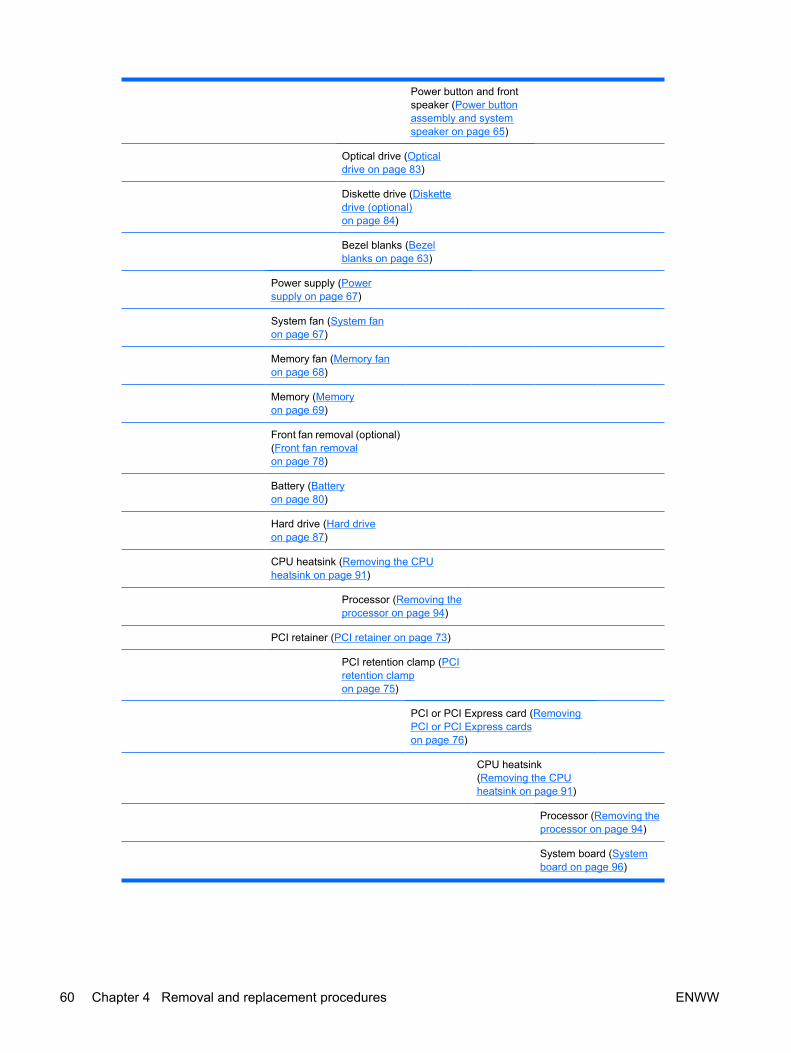
Power button and frontspeaker (Power buttonassembly and systemspeaker on page 65)
Optical drive (Opticaldrive on page 83)
Diskette drive (Diskettedrive (optional)on page 84)
Bezel blanks (Bezelblanks on page 63)
Power supply (Powersupply on page 67)
System fan (System fanon page 67)
Memory fan (Memory fanon page 68)
Memory (Memoryon page 69)
Front fan removal (optional)(Front fan removalon page 78)
Battery (Batteryon page 80)
Hard drive (Hard driveon page 87)
CPU heatsink (Removing the CPUheatsink on page 91)
Processor (Removing theprocessor on page 94)
PCI retainer (PCI retainer on page 73)
PCI retention clamp (PCIretention clampon page 75)
PCI or PCI Express card (RemovingPCI or PCI Express cardson page 76)
CPU heatsink(Removing the CPUheatsink on page 91)
Processor (Removing theprocessor on page 94)
System board (Systemboard on page 96)
60 Chapter 4 Removal and replacement procedures ENWW
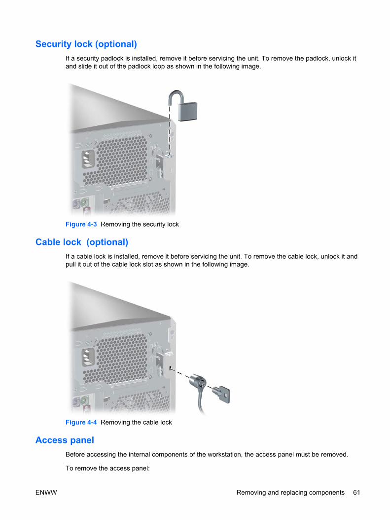
Security lock (optional)If a security padlock is installed, remove it before servicing the unit. To remove the padlock, unlock itand slide it out of the padlock loop as shown in the following image.
Figure 4-3 Removing the security lock
Cable lock (optional) If a cable lock is installed, remove it before servicing the unit. To remove the cable lock, unlock it andpull it out of the cable lock slot as shown in the following image.
Figure 4-4 Removing the cable lock
Access panel Before accessing the internal components of the workstation, the access panel must be removed.
To remove the access panel:
ENWW Removing and replacing components 61

WARNING! Before removing the workstation access panel, be sure that the workstation ispowered off and that the power cord is disconnected from the electrical outlet.
1. Disconnect power from the system.
2. If a lock is present, unlock the access panel (Access panel on page 61). The keys are on the rearpanel (Rear panel components on page 4). Also, unlock any other locks that are present(Kensington, or Padlock).
3. Pull up on the handle and lift off the cover.
Figure 4-5 Opening the access panel
To replace the access panel, align the bottom groove of the access panel with the bottom edge of thechassis. Rotate the access panel toward the chassis and press firmly until the latch engages.
Front bezel To remove the front bezel:
1. Lift up on the three (1) tabs located on the front bezel.
2. Rotate the front bezel away (2) from the chassis, and remove the bezel.
62 Chapter 4 Removal and replacement procedures ENWW

Figure 4-6 Opening the front bezel
Bezel blanks To remove the bezel blanks:
1. Disconnect power from the system, ( Pre-disassembly procedures on page 55), remove the accesspanel, and remove the front bezel (Front bezel on page 62)
2. Remove the bezel blanks by squeezing in on the tabs (1) and pulling in the bezel blanks (2).
Figure 4-7 Removing the bezel blanks
ENWW Removing and replacing components 63

Hood sensor (Smart cover sensor)To remove the hood sensor:
1. Disconnect power from the system ( Pre-disassembly procedures on page 55) and remove theaccess panel (Access panel on page 61). Remove the front bezel. Lay the workstation on its sidewith the system board facing up.
2. Remove the two hood sensor bracket screws, and remove the bracket and sensor as a unit.
Figure 4-8 Removing the hood sensor
To replace the hood sensor, reverse the previous steps.
Front panel I/O device assembly To remove the front panel I/O device assembly:
1. Disconnect power from the system ( Pre-disassembly procedures on page 55). Remove the accesspanel (Access panel on page 61) and the front bezel (Front bezel on page 62).
2. Unlatch the plastic snap that secures the cables inside the chassis and, disconnect the front panelI/O device assembly cables from the system board.
3. Remove the screws that hold the front panel I/O device assembly and bracket to the chassis, andremove the screws that hold the front panel I/O device assembly to the bracket.
4. Pull the front panel I/O device assembly out about two inches away from the chassis.
64 Chapter 4 Removal and replacement procedures ENWW
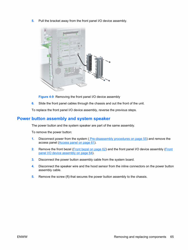
5. Pull the bracket away from the front panel I/O device assembly.
Figure 4-9 Removing the front panel I/O device assembly
6. Slide the front panel cables through the chassis and out the front of the unit.
To replace the front panel I/O device assembly, reverse the previous steps.
Power button assembly and system speaker The power button and the system speaker are part of the same assembly.
To remove the power button:
1. Disconnect power from the system ( Pre-disassembly procedures on page 55) and remove theaccess panel (Access panel on page 61).
2. Remove the front bezel (Front bezel on page 62) and the front panel I/O device assembly (Frontpanel I/O device assembly on page 64).
3. Disconnect the power button assembly cable from the system board.
4. Disconnect the speaker wire and the hood sensor from the inline connectors on the power buttonassembly cable.
5. Remove the screw (1) that secures the power button assembly to the chassis.
ENWW Removing and replacing components 65

6. Dislodge the metal clip from the chassis by rocking the power button back and forth. Then slidethe power button assembly (2) out from the front of the chassis.
Figure 4-10 Removing the power button assembly
To remove the speaker:
1. Disconnect the speaker cable from the in-line front panel I/O device assembly cable, if you havenot already done so.
2. Slide the speaker away from the three flanges and remove it from the chassis.
Figure 4-11 Removing the speaker
66 Chapter 4 Removal and replacement procedures ENWW

Power supply1. Disconnect power from the system ( Pre-disassembly procedures on page 55), and remove the
access panel (Access panel on page 61). Place the workstation on its side with the system boardfacing up.
2. Disconnect the three power supply cable connectors from the system board.
NOTE Cable ties and cable clips may be present.
3. Disconnect the power supply connections from the optical drives, diskette drive, hard drives, andgraphics card (select models only).
4. Remove the four screws (1) from the back panel.
5. Slide the power supply toward the front, and lift up (2) to remove it from the chassis.
Figure 4-12 Removing the power supply
To install the power supply, reverse the previous steps.
System fanTo remove the system fan:
1. Disconnect power from the system ( Pre-disassembly procedures on page 55), and remove theaccess panel (Access panel on page 61). Place the workstation on its side with the system boardfacing up.
2. Disconnect the fan power plug from the system board (1).
ENWW Removing and replacing components 67

3. Press down on the ribbed portion of the system fan housing (2), rotate the fan housing down, andlift the unit out of the chassis.
Figure 4-13 Removing the system fan
To replace the system fan, reverse the previous steps.
CAUTION When installing the system fan, be sure that the fan is situated so that the airflowdirection is going out of the chassis to avoid overheating.
Memory fanTo remove the memory fan:
1. Disconnect power from the system ( Pre-disassembly procedures on page 55), and remove theaccess panel (Access panel on page 61). Place the workstation on its side with the system boardfacing up.
2. Disconnect the memory fan power plug from the system board (1).
NOTE If the fan is simply being moved to access the DIMMs, it does not need to bedisconnected from the system board.
68 Chapter 4 Removal and replacement procedures ENWW
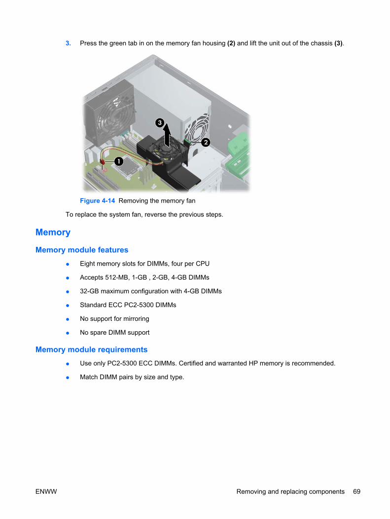
3. Press the green tab in on the memory fan housing (2) and lift the unit out of the chassis (3).
Figure 4-14 Removing the memory fan
To replace the system fan, reverse the previous steps.
Memory
Memory module features
● Eight memory slots for DIMMs, four per CPU
● Accepts 512-MB, 1-GB , 2-GB, 4-GB DIMMs
● 32-GB maximum configuration with 4-GB DIMMs
● Standard ECC PC2-5300 DIMMs
● No support for mirroring
● No spare DIMM support
Memory module requirements
● Use only PC2-5300 ECC DIMMs. Certified and warranted HP memory is recommended.
● Match DIMM pairs by size and type.
ENWW Removing and replacing components 69

Removing memory module1. Disconnect power from the system ( Pre-disassembly procedures on page 55), and remove the
access panel (Access panel on page 61). Place the workstation on its side with the system boardfacing up.
CAUTION To ensure that memory modules are not damaged during removal orinstallation, power off the workstation and unplug the power cord from the AC power outlet.Wait until the LED on the back of the power supply turns off before removing memory. If youdo not unplug the power cord while installing memory, your memory modules might bedamaged and the system will not recognize the memory changes.
2. Press the green tab in on the memory fan housing (1) and lift the unit out of the chassis (2).
Figure 4-15 Removing memory fan
NOTE The system fan (System fan on page 67 )must also be removed to access DIMMsin the rear slots.
3. Gently push out on the socket levers (1).
70 Chapter 4 Removal and replacement procedures ENWW
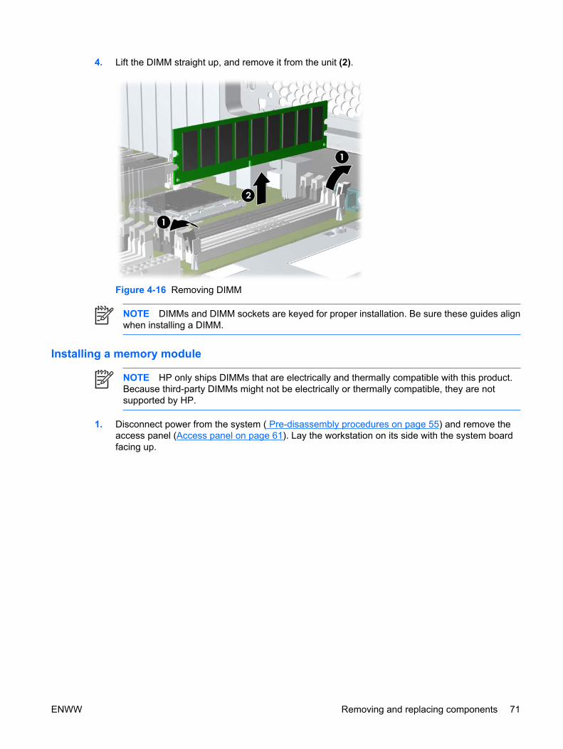
4. Lift the DIMM straight up, and remove it from the unit (2).
Figure 4-16 Removing DIMM
NOTE DIMMs and DIMM sockets are keyed for proper installation. Be sure these guides alignwhen installing a DIMM.
Installing a memory module
NOTE HP only ships DIMMs that are electrically and thermally compatible with this product.Because third-party DIMMs might not be electrically or thermally compatible, they are notsupported by HP.
1. Disconnect power from the system ( Pre-disassembly procedures on page 55) and remove theaccess panel (Access panel on page 61). Lay the workstation on its side with the system boardfacing up.
ENWW Removing and replacing components 71

2. Depress the green tabs on the memory fan housing (1) and lift the unit out of the chassis (2).
Figure 4-17 Removing the memory fan
3. Gently push out on the socket levers.
4. Prepare to load memory modules in valid configurations:
● DIMMs must be loaded in matched pairs.
● If loading two DIMMs, install them in slots 1a/1b.
● If loading four DIMMs, install them in slots 1a/1b and 2a/2b for a dual CPU system, or in 1a/1b and 3a/3b for a single CPU system.
● If loading six DIMMs, install them in slots 1a/1b, 2a/2b, and 3a/3b.
● If loading eight DIMMs, install them in all slots.
● Load the memory module pairs in order of size, from largest to smallest.
24 1
3
Figure 4-18 Identifying memory slots
5. Lower the DIMM straight down, and be sure the socket levers secure the module into place.
NOTE DIMMs and DIMM sockets are keyed for proper installation. Be sure these guidesalign when installing a DIMM.
6. Lower the memory fan until it snaps into place.
NOTE Ensure that all cables are clear of the fan housing when lowering the memory fan.
72 Chapter 4 Removal and replacement procedures ENWW

The BIOS generates warnings/errors on invalid memory configurations.
● If BIOS cannot obtain a valid memory configuration, it will halt the system with a diagnostics 2006code for memory error (five beeps and blinks).
● If memory node interleave is enabled but the memory installed on the two CPUs is not equal, BIOSwill report a warning during POST (“215-Cannot Interleave Unequal Memory Nodes”). The systemcan still boot in this condition.
PCI slots
Figure 4-19 Identifying PCI slots
Table 4-4 PCI slots
Slot Type Ref
1 PCI Express x16 (x8) J31
2 PCI Express x16 graphics J41
3 PCI 32 bit, 33 MHz J20
4 PCI Express x16 (x8) J33
5 PCI Express x16 graphics J32
6 PCI-X 100 J25
7 PCI-X 100/133 J26
PCI retainer For added protection, some cards have PCI retainers installed to prevent movement during shipping.
ENWW Removing and replacing components 73

Removing the PCI retainer
1. Disconnect power from the system ( Pre-disassembly procedures on page 55), and remove theaccess panel (Access panel on page 61). Place the workstation on its side with the system boardfacing up.
2. For both short and tall cards, press in on the sides (1) of the retainer, and rotate it (2) out of thechassis.
Figure 4-20 Removing the short or tall card PCI retainer
Installing the PCI retainer
1. Disconnect power from the system ( Pre-disassembly procedures on page 55), and remove theaccess panel (Access panel on page 61). Place the workstation on its side with the system boardfacing up.
74 Chapter 4 Removal and replacement procedures ENWW

2. For both short and tall PCI cards, attach the hooks of the PCI retainer (1) under the slots on therear of the chassis, and then rotate the retainer down until the retainer arm (2) supports the card.
Figure 4-21 Installing the short or tall card PCI retainer
PCI retention clamp 1. Disconnect power from the system ( Pre-disassembly procedures on page 55), and remove the
access panel (Access panel on page 61). Place the workstation on its side with the system boardfacing up.
2. Open the PCI retention clamp by pressing down on the two green clips at the ends of the clampand rotating the clamp toward the back of the system.
Figure 4-22 Opening the PCI retention clamp
PCI Express PCI Express is a point-to-point architecture and uses a serial data transmission protocol. A single PCIExpress lane consists of four wires and can transmit 250 MB/s in a single direction or 500 MB/s in both
ENWW Removing and replacing components 75

directions simultaneously. This bandwidth is not affected by what is happening on other PCI Expressbuses or legacy PCI/PCI-X buses (provided that total bandwidth can be handled by the CPU and thememory subsystem.) The transmission protocol is somewhat similar to that used for a LAN connectionand contains error correction and detection, packet addressing, and other network features.
PCI Express improves system attributes. PCI Express enables a low-power, scalable, high-bandwidthcommunication path with a small number of connections (wires) compared to traditional parallelinterfaces (for example, PCI).
The PCI Express I/O slots can support other PCI Express cards with lesser bus bandwidth than what isphysically defined for the slot. Use the following table to determine compatibility.
For example, a PCI Express x8 card does not work in a PCI Express x1 slot, but a PCI Express x1 cardworks in a PCI Express x8 slot.
Table 4-5 PCI Express compatibility matrix for xw9400
Slot 1*
x16 mechanical
x8 electrical
Slot 2
x16 mechanical
x16 electrical
Slot 4
x16 mechanical
x8 electrical
Slot 5
x16 mechanical
x16 electrical
PCI Express x1Card
Yes Yes Yes Yes
PCI Express x4Card
Yes Yes Yes Yes
PCI Express x8Card
Yes Yes Yes Yes
PCI Express x16Card
Yes Yes Yes Yes
* Slot 1 is for short cards only.
Removing PCI or PCI Express cards 1. Disconnect power from the system ( Pre-disassembly procedures on page 55), and remove the
access panel (Access panel on page 61). Place the workstation on its side with the system boardfacing up. Remove the PCI retainer (PCI retainer on page 73) if present.
2. Open the PCI retention clamp by pressing down on the two green clips at the ends of the clamp(1) and rotating the clamp toward the back of the system.
76 Chapter 4 Removal and replacement procedures ENWW
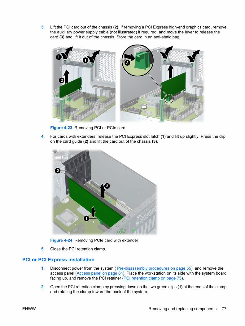
3. Lift the PCI card out of the chassis (2). If removing a PCI Express high-end graphics card, removethe auxiliary power supply cable (not illustrated) if required, and move the lever to release thecard (3) and lift it out of the chassis. Store the card in an anti-static bag.
Figure 4-23 Removing PCI or PCIe card
4. For cards with extenders, release the PCI Express slot latch (1) and lift up slightly. Press the clipon the card guide (2) and lift the card out of the chassis (3).
Figure 4-24 Removing PCIe card with extender
5. Close the PCI retention clamp.
PCI or PCI Express installation1. Disconnect power from the system ( Pre-disassembly procedures on page 55), and remove the
access panel (Access panel on page 61). Place the workstation on its side with the system boardfacing up, and remove the PCI retainer (PCI retention clamp on page 75).
2. Open the PCI retention clamp by pressing down on the two green clips (1) at the ends of the clampand rotating the clamp toward the back of the system.
ENWW Removing and replacing components 77

3. Remove the PCI slot cover (2).
4. Lower the PCI (3) or PCI Express (3) card into the chassis. Verify that the keyed components ofthe card align with the socket.
If installing a card with an auxiliary power connector, plug in the power supply cable or adaptercable supplied with the card (4).
5. Ensure that all cards are properly seated, and close the PCI retention clamp.
Figure 4-25 Installing PCI or PCIe card
Front fan removal To remove the front fan:
1. Disconnect power from the system ( Pre-disassembly procedures on page 55), and remove theaccess panel (Access panel on page 61). Place the workstation on its side with the system boardfacing up.
2. Disconnect optical and floppy drive cables from the system board. Remove full length PCI cards.
3. Disconnect the front fan cable from the connector on the system board.
78 Chapter 4 Removal and replacement procedures ENWW

4. Release the two card guide latches (1), pivot the card guide toward the system board (2), and liftit out of the chassis (3).
Figure 4-26 Removing card guide
5. Remove the fan from the card guide by releasing the two latches and applying outward pressureon the card guide while lifting the fan away.
Figure 4-27 Removing fan from card guide
To install the front fan:
1. Place the fan in the card guide with the fan label facing into the card guide, and the fan protectorscreen facing outward.
NOTE Ensure that the fan blows toward the rear of the chassis.
2. Thread the front fan cable through the slot in the card guide.
ENWW Removing and replacing components 79

3. Set the front fan in the card guide and snap the fan into place.
Figure 4-28 Installing the fan in card guide
4. Lower the card guide with installed fan into the chassis. Place the card guide tabs into the chassisslots and snap the card guide into place.
5. Plug the front fan cable into its connector on the system board.
Battery
CAUTION Before removing the battery, be sure your CMOS settings are backed up becauseall CMOS settings are lost when the battery is removed. To back up the CMOS settings, useComputer Setup and run the Save to Diskette option from the File menu.
To remove the battery:
1. Disconnect power from the system ( Pre-disassembly procedures on page 55), and remove theaccess panel (Access panel on page 61). Place the workstation on its side with the system boardfacing up.
2. On the system board, press on the release tab of the battery holder.
3. Rotate the battery enough to get beyond the latch, and lift it straight up.
80 Chapter 4 Removal and replacement procedures ENWW

Figure 4-29 Removing the battery
To install the battery, slide the battery into the holder until it snaps into place.
Power connections to drives For help in identifying power cables, refer to the following figure and table. Route or tie cables so thatthey cannot interfere with the CPU heatsink fans.
ENWW Removing and replacing components 81

Figure 4-30 Identifying correct power connections
Table 4-6 Power connector descriptions
Connector Description
P1 24-pin main power connector
P2 4-pin memory powerconnector
P3 8-pin processor powerconnector
P4–P8 SATA and IDE ODD/accessory power connectors
P9 Diskette connector
P10–P14 HDD connector
P15 PCIe connector
P16 PCIe connector
82 Chapter 4 Removal and replacement procedures ENWW

Optical drive Your workstation might have a SATA or an IDE optical drive. To remove the optical drive:
1. Disconnect power from the system ( Pre-disassembly procedures on page 55). Remove the accesspanel (Access panel on page 61) and the front bezel (Front bezel on page 62).
2. Disconnect the audio (1), data (2), and power (3) cables from the drive. The connector colors mightbe different than illustrated.
NOTE The audio cable is only required for Linux-based systems.
Figure 4-31 Disconnecting IDE (left) or SATA (right) cable from optical drive
3. Lift the green drivelock release lever, and gently slide the drive out of the chassis.
Figure 4-32 Removing optical drive from chassis
ENWW Removing and replacing components 83

To replace an optical drive:
1. Lift the green drivelock release lever while sliding the optical drive into the bay. When the opticaldrive is partially inserted, release the drivelock release lever, and slide the drive completely intothe bay until the drive is secured.
CAUTION Ensure that the optical drive is secure. Failure to do so can cause damage tothe drive when moving the workstation.
2. Connect the power, data , and audio (if required) cables to the drive and workstation.
NOTE The audio cable is only required for Linux-based systems.
3. If you are installing more than one optical drive, route the cable as in the following image.
Figure 4-33 Connecting IDE (left) or SATA (right) optical drive cable to system board
Replacing the SATA optical drive data cableIf your workstation has a SATA optical drive, replace the cable as follows:
1. Disconnect power from the system ( Pre-disassembly procedures on page 55), and remove theaccess panel (Access panel on page 61). Place the workstation on its side with the system boardfacing up.
2. Disconnect the SATA data cable from the system board and from the optical drive.
3. Replace the cable. Attach it to the optical drive and its system board connector as shown.
Diskette drive (optional) To remove a diskette drive:
1. Disconnect power from the system ( Pre-disassembly procedures on page 55). Remove the accesspanel (Access panel on page 61) and the front bezel (Front bezel on page 62).
84 Chapter 4 Removal and replacement procedures ENWW

2. Disconnect the cables from the back of the diskette drive.
Figure 4-34 Disconnecting cables from the diskette drive
3. While lifting the green drivelock release tab, slide the drive forward out of the chassis.
Figure 4-35 Removing the diskette drive from the chassis
ENWW Removing and replacing components 85

4. Remove the diskette drive from its bracket by removing the two M3 screws in the rear-most holesand pulling the diskette drive from the bracket.
Figure 4-36 Removing the diskette drive from the bracket
To replace a diskette drive:
1. Slide the diskette drive into the bracket, and secure it with two M3 screws.
2. While lifting the green drivelock release tab, slide the drive into the chassis.
3. Route the diskette drive data cable between the system board and the hard drive cage. Your cablemight look different than the one shown.
Figure 4-37 Routing the diskette drive cable to the system board
4. Connect the cables to the back of the diskette drive.
86 Chapter 4 Removal and replacement procedures ENWW
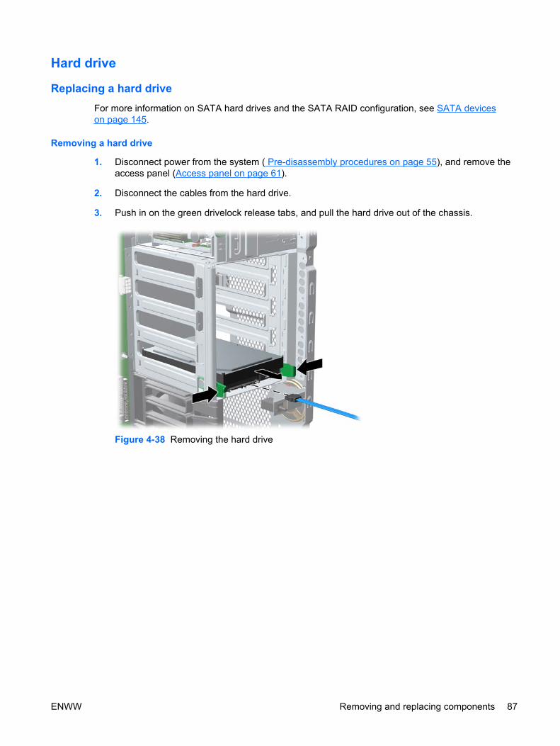
Hard drive
Replacing a hard driveFor more information on SATA hard drives and the SATA RAID configuration, see SATA deviceson page 145.
Removing a hard drive
1. Disconnect power from the system ( Pre-disassembly procedures on page 55), and remove theaccess panel (Access panel on page 61).
2. Disconnect the cables from the hard drive.
3. Push in on the green drivelock release tabs, and pull the hard drive out of the chassis.
Figure 4-38 Removing the hard drive
ENWW Removing and replacing components 87

Installing a hard drive
1. Select a drive bay in which to install the drive. If installing more than one hard drive, use the harddrive order shown in the following image.
Figure 4-39 Identifying hard drive installation order
2. Squeeze the green tabs, and slide the rails out of the empty bay.
3. Attach the rails to the hard drive. Align the pins on the rails with the hard drive holes, and snap therails into place.
Figure 4-40 Attaching rails to the hard drive
4. Push the drive into the selected bay until it snaps into place.
88 Chapter 4 Removal and replacement procedures ENWW

5. Attach a data cable from a SATA connector on the system board to the hard drive, and attach apower cable to the drive.
Figure 4-41 Replacing the SATA hard drive
6. For a SAS hard drive, attach a SAS/SATA adapter to the connector on the hard drive. Attach adata cable from a SAS connector on the system board to the hard drive, and attach a power cableto the drive.
Figure 4-42 Installing the SAS/SATA adapter (left) and cable (right)
ENWW Removing and replacing components 89

Installing a hard drive In the fifth hard drive bayTo install a hard drive into fifth HDD bay:
1. Place the workstation on its side, and remove the three drive screws that are located on the bottomof the chassis.
Figure 4-43 Installing screws for the hard drive in the fifth hard drive bay
2. Insert the drive into bay 5, and align the holes in the bottom of the hard drive with the screw holesat the base of the chassis.
3. Insert the screws through the base, and tighten them to secure the hard drive to the chassis.
4. Attach a data cable from a SATA connector on the system board to the hard drive, and attach thefifth drive power cable to the drive. It is attached to a clip in front of the power supply.
Figure 4-44 Attaching the data cable for the SATA hard drive in the fifth hard drive bay
90 Chapter 4 Removal and replacement procedures ENWW
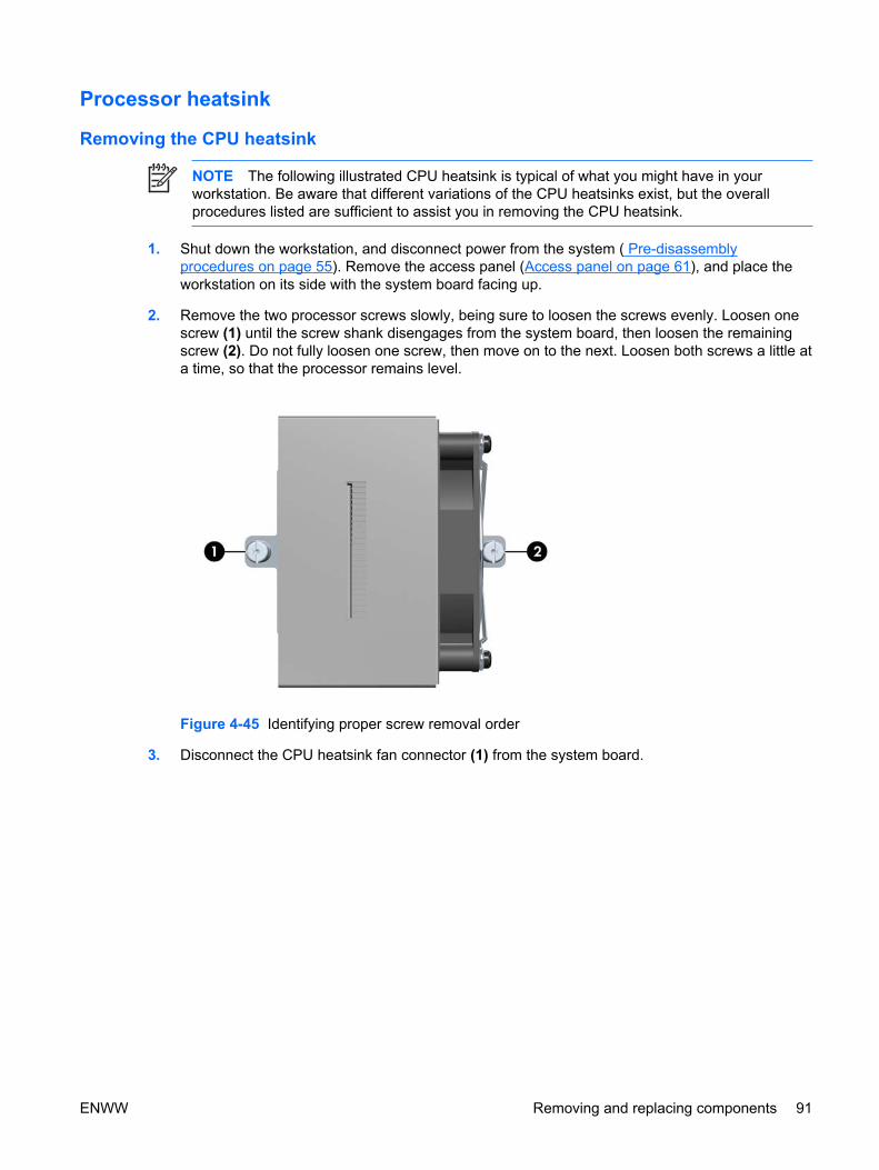
Processor heatsink
Removing the CPU heatsink
NOTE The following illustrated CPU heatsink is typical of what you might have in yourworkstation. Be aware that different variations of the CPU heatsinks exist, but the overallprocedures listed are sufficient to assist you in removing the CPU heatsink.
1. Shut down the workstation, and disconnect power from the system ( Pre-disassemblyprocedures on page 55). Remove the access panel (Access panel on page 61), and place theworkstation on its side with the system board facing up.
2. Remove the two processor screws slowly, being sure to loosen the screws evenly. Loosen onescrew (1) until the screw shank disengages from the system board, then loosen the remainingscrew (2). Do not fully loosen one screw, then move on to the next. Loosen both screws a little ata time, so that the processor remains level.
Figure 4-45 Identifying proper screw removal order
3. Disconnect the CPU heatsink fan connector (1) from the system board.
ENWW Removing and replacing components 91

4. Before lifting the heatsink, carefully break the adhesive compound between the CPU heatsink andprocessor by moving the heatsink back and forth or twisting it (2).
Figure 4-46 Removing the CPU heatsink from the system board
5. Use alcohol and a soft cloth to clean all of the thermal interface material residue from the CPUheatsink and processor.
CAUTION Allow the alcohol on the processor and CPU heatsink to dry completely.
Replacing the CPU heatsink1. Disconnect power from the system ( Pre-disassembly procedures on page 55). Remove the access
panel (Access panel on page 61) and the CPU heatsink (Removing the CPU heatsinkon page 91).
2. Use alcohol and a soft cloth to clean all of the thermal interface material residue from the CPUheatsink and processor.
CAUTION Allow the alcohol on the processor and CPU heatsink to dry completely.
3. Place the CPU heatsink on top of the processor, and align the two mounting screws with theholes (1) in the system board.
NOTE If both CPU heatsinks were removed, be sure that all system board standoffsengage with the keyholes in the chassis, and that the system board connectors engagecorrectly with the rear I/O panel, and push back on the system board while engaging theCPU heatsink screws with the chassis standoffs. You only need to push back when tryingto engage the first sc rew.
92 Chapter 4 Removal and replacement procedures ENWW

4. Connect the CPU heatsink fan connector to the system board (2).
Figure 4-47 Replacing the CPU heatsink on the system board
5. Insert and tighten the two CPU heatsink screws. First, tighten both screws partially so that the CPUheatsink remains level. Next, fully tighten one screw (1), then fully tighten the remaining screw(2). Tighten to a torque setting of 6 in-lb.
Figure 4-48 Identifying proper screw removal order
ENWW Removing and replacing components 93

Processor
Removing the processor
CAUTION Use extreme care when installing or removing a processor. The exposed socketpins are extremely fragile. Damaged sockets will require a board replacement.
Lift the processor out of the socket— do not slide the processor on the socket.
When installing a processor, align the dimples on the side of the processor with the notches inthe socket.
1. Disconnect power from the system ( Pre-disassembly procedures on page 55). Remove the accesspanel (Access panel on page 61) and the CPU heatsink (Removing the CPU heatsinkon page 91).
2. Raise the processor socket handle fully (1) and lift the socket cover (2).
Figure 4-49 Raising the processor socket handle
94 Chapter 4 Removal and replacement procedures ENWW

3. Lift the processor straight out of the socket.
Figure 4-50 Lift the processor from the socket
CAUTION To avoid bending the socket pins, keep the processor perfectly flat whenremoving or installing it.
NOTE Store the processor in a static-free, safe place where it will not be damaged.
4. In some workstation configurations, a bypass board may be installed in the socket instead of aprocessor. Remove the bypass board by lifting it straight out of the socket.
Figure 4-51 Lift the bypass board from the socket
ENWW Removing and replacing components 95

Replacing the processor
CAUTION Use extreme care when installing or removing a processor. The exposed socketpins are extremely fragile. Damaged sockets will require a board replacement.
Lift the processor out of the socket— do not slide the processor on the socket.
When installing a processor, align the dimples on the side of the processor with the notches inthe socket.
1. Disconnect power from the system ( Pre-disassembly procedures on page 55). Remove the accesspanel (Access panel on page 61), the CPU heatsink (Removing the CPU heatsink on page 91),and the processor (Removing the processor on page 94).
2. Raise the processor socket handle fully.
3. If necessary, remove the bypass board from the socket. Align the notches in the processor basewith the tabs on the socket. Seat the processor into the socket. Ensure that the underside of theprocessor is level with the top of the processor socket. Close the processor cover plate. Lightlypress down on the processor cover plate while closing the socket lever.
Figure 4-52 Seating the processor
System board
Removing the system board1. Disconnect power from the system ( Pre-disassembly procedures on page 55), and remove the
access panel (Access panel on page 61). Place the workstation on its side with the system boardfacing up. Remove all expansion boards, external cables, graphics cards (Removing PCI or PCIExpress cards on page 76), and the CPU heatsink (Processor heatsink on page 91). Remove thesystem and memory fan assemblies.
2. Disconnect all cables from the system board.
NOTE Make note of the cable connections before disconnecting them from the systemboard. See Power connections to drives on page 81for more information.
96 Chapter 4 Removal and replacement procedures ENWW

3. Rotate the system board latch lever 90 degrees (1) clockwise to unlock the system board.
4. Slide the system board forward (2) to disengage the metal mounting standoffs from the chassis.
CAUTION Do not attempt to remove the system board mounting screws. These screwsare permanently secured and are not removable.
5. Lift the system board out (3) of the chassis, being careful not to damage the cables and rear panelconnectors. You can lift the board by the rear audio connector and the 2 x 4 power connector (4).
Figure 4-53 Removing the system board
Replacing the System Board1. Insert the system board straight down, and be sure that all system board standoffs engage with
the keyholes in the chassis.
NOTE Be sure the system board connectors engage correctly with the rear I/O panel.
2. Push back on the board while maintaining downward pressure on the board, so all standoffs remainengaged.
3. Rotate the system board latch 90 degrees counter clockwise.
4. Install the heatsink (Replacing the CPU heatsink on page 92).
5. Install all removed components and cables.
ENWW Removing and replacing components 97

98 Chapter 4 Removal and replacement procedures ENWW

5 System diagnostics andtroubleshooting
This chapter discusses the tools available for diagnosing and troubleshooting system issues.
● E-Support on page 100
● Troubleshooting checklist on page 101
● LED color definitions on page 102
● HP Insight Diagnostics Offline Edition on page 103
● Diagnostic error codes on page 107
● Troubleshooting scenarios and solutions on page 110
● POST error messages on page 131
ENWW 99

E-SupportHelp and support center and E-Support
Help and Support Center (HSC) provides online access to technical support information, softwareupdates and downloads, diagnostic tools, and HP support contact information.
To open HSC from your desktop, click Start>Help and Support.
HSC contains four sections:
● HP Product Information (requires Internet access)—Links to the HP Technical Support website foryour product. You can access all related documentation, downloads and updates, tools, and more.
● HP Software and Driver Downloads (requires Internet access)—Links to HP specific softwaredownloads and updates.
● HP Support Tools (requires Internet access)—Links to self-help tools and diagnostics offered byHP Instant Support Professional Edition.
● Contact HP for Support—Provides two different options:
● Chat with an expert online (requires Internet access)—Provides a tool to communicate witha support specialist online through Active Chat.
● Call a support agent—Provides hardware details about the workstation and HP supportcontact phone number worldwide.
100 Chapter 5 System diagnostics and troubleshooting ENWW

Troubleshooting checklistBefore running any of the diagnostic utilities, use the following checklist to find possible solutions forworkstation or software problems.
● Are the workstation and monitor connected to a working electrical outlet?
● Is the workstation powered on?
● Is the green power light illuminated?
● Is the monitor powered on?
● Is the green monitor light illuminated?
● Adjust the monitor brightness and contrast controls if the monitor is dim.
● Press and hold any key. If the system beeps, then the keyboard is operating correctly.
● Examine all cables for loose or incorrect connections.
● Reconfigure the workstation after installing a non-PnP (Plug 'n Play) expansion board or otheroption, such as a diskette drive.
● Are all of the necessary device drivers installed?
● Have all printer drivers been installed for each application?
● Remove all diskettes and CDs from the drives before you power on the system.
● Are you running the latest BIOS version, drivers, and/or software updates?
ENWW Troubleshooting checklist 101

LED color definitions The front panel LED indicates system status as described in Table 1.
Table 5-1 Front panel LED color definitions
LED State LED Color System Status
Solid Green System is on.
Blinking Green System is in Standby mode.
Solid or blinking Red System has an error. See Diagnostic light codeson page 107.
None No light System is in Hibernate mode, or it is off.
102 Chapter 5 System diagnostics and troubleshooting ENWW

HP Insight Diagnostics Offline EditionThe HP Insight Diagnostics utility enables you to perform testing and to view critical computer hardwareand software configuration information from various sources. This utility enables you to:
● Run diagnostics.
● View the hardware configuration of the system.
Key features and benefitsHP Insight Diagnostics simplifies the process of effectively identifying, diagnosing, and isolating thehardware issues.
In addition to robust management tools, service tools can be invaluable in quickly resolving systemproblems. To streamline the service process and resolve problems quickly, you must have the rightinformation available at the time you place a service call. The primary information requirement, whichis also the one that provides the greatest insight into potential system issues, is the configuration of thesystem. Insight Diagnostics helps provide higher system availability. Typical uses of the InsightDiagnostics are:
● Testing and diagnosing apparent hardware failures
● Documenting system configurations for upgrade planning, standardization, inventory tracking,disaster recovery, and maintenance
● Sending configuration information to another location for more in-depth analysis
Theory of operationHP Insight Diagnostics Offline Edition operates in offline mode only. Here, the operating system is notrunning, and software information from the system is not available to the diagnostics.
Offline Survey is available to display the current system configuration.
The Insight Diagnostics Test feature enables you to test functionality of all the major hardwarecomponents in the system. The Test feature is designed to be flexible to enable you to customize testselections by providing different modes and types of testing. It includes Quick, Complete, and Customtesting levels to give you control over testing depth and required user interaction.
Download the ISO image
1. Browse to http://www.hp.com.
2. Click Software & Driver Downloads.
3. Enter your product number (for example, xw9400) in the text box, and press the Enter key.
4. Select your operating system.
5. Click the Diagnostic link.
6. Locate HP Insight Diagnostics Offline on the display, and click Download.
ENWW HP Insight Diagnostics Offline Edition 103
User interface
NavigationThe Insight Diagnostics home page contains the following tabs: Survey, Test, Status, Log, andHelp. These tabs separate the major functions of Insight Diagnostics.
Survey tabWhen you click the Survey tab, the Survey menu displays and enables you to view important systemconfiguration information. The Summary view limits the amount of data displayed, while theAdvanced view shows all the data in the selected category. Regardless of whether you chooseAdvanced or Summary, the following categories of information are available on the Survey menu:
Overview—Lists general information about the computer.
All—Lists all information about the computer.
Architecture—Shows the type of bus the computer uses, and BIOS information. In addition, if the busis PCI, information about the PCI configuration is displayed.
Asset Control—Shows the serial number of the computer, and provides processor information.
Communication—Shows information about the computer parallel (LPT) and serial (COM) port settings,USB, and network controller information.
Graphics—Shows information about the graphics subsystem of the computer.
Input Devices—Shows information about the type of keyboard and mouse.
Memory—Shows information about all memory in the computer, including memory on the board andany memory modules installed.
Miscellaneous—Shows information obtained from the computers configuration memory (CMOS), BIOSdata area, Interrupt Vector table, and diagnostics component information.
Storage—Shows information about storage media connected to the computer, including all fixed disks,floppy drives, and CD-ROM drives.
System—Shows product type, processor type and speed, and coprocessor information, and informationabout all ROMs in the computer.
Test tabThe Insight Diagnostics utility enables you to test all the major pieces of hardware in the system. Youcan select from several types of tests:
Quick Test—Provides a predetermined script in which a sample of most hardware components isexercised and requires no user intervention.
Complete Test—Provides a predetermined script in which most hardware components are fully tested.You can select Interactive or Unattended tests, which will change the devices tested during the CompleteTest. More tests are available in Interactive mode, but these require user intervention.
Custom Test—Provides the most flexibility in controlling the testing of a system. The Custom Test modeenables you to select which devices, tests, and test parameters are run. You can select tests that donot require any user interaction through the Interactive or Unattended test modes. More tests areavailable in Interactive mode, but these require user intervention.
104 Chapter 5 System diagnostics and troubleshooting ENWW

To begin testing:
1. Click the Test tab.
2. Select Type of Test to perform, and select Interactive or Unattended as the test mode.
3. Determine how you want the test to be executed.
● Select Number of Loops and enter the number of loops to perform.
● Select Total Test Times and enter the amount of time in minutes that you want the diagnostictest to run.
4. When choosing to run the test over a specified number of loops, enter the number of loops toperform. If you desire to have the diagnostic test for a specified time period, enter the amount oftime in minutes.
5. Click Begin Testing in the lower right corner of the display to start the test.
While tests are being performed, you can monitor the progress by clicking the Status tab. Any errorsthat are detected are summarized in the Error Log. Click Save to save the report to a floppy disk or aUSB key drive if attached.
If the diagnostics utility detects an error during a test, you can mouse-over the failed text in the Statustab to display additional information for the type of error and the error code.
To view all test failure information, select Error Log. To view the status of all testing that has beenperformed, click the Log tab.
Status tabThe Status tab displays the status of the selected tests. The type of test executed (for example,Quick, Complete, Custom) is displayed. The main progress bar displays the percent complete of thecurrent set of tests. While testing is in progress, a Cancel Testing button is activated. Clicking CancelTesting cancels the test job.
After testing has completed the Cancel Testing button is replaced with two buttons, Select NewTests and Retest. Clicking the Select New Tests button enables you to go back to the previous testselection page to select a new set of tests. Clicking the Retest button runs the last set of tests executedwithout having to go back to the test selection page.
The Status page also shows the:
● Devices being tested
● Tests that are running
● Overall test time
● Individual test times
● Condition status of each test
Log tabThe Log tab consists of two views:
ENWW HP Insight Diagnostics Offline Edition 105

Test Log—Displays all tests that have been executed, the number of times the test executed, thenumber of times the test failed, and the time it took to complete the test. Clicking the Clear Test Logbutton clears the contents of the Test Log.
Error Log—Displays the tests that have failed during the diagnostic testing. Besides displaying thedevice and test, this section might also include error details. The description section describes the errorthat the diagnostic test found. Clicking the Recommended Repair button gives a recommended actionthat should be performed to resolve the failed hardware. Te error count is the number of times the testhas failed. Clicking the Clear Error Log button clears the contents of the Error Log.
Help tabThe Help tab has three views:
● HP Insight Diagnostics—Provides introductory and detailed information about Insight FieldDiagnostics.
● Error Codes—Provides error code listings. It includes device tested, message, and recommendedrepair information.
● Test Components—Reloads and refreshes all components and display component details afterthe refresh.
The Help tab provides information option selections:
● Reload—Located in the upper-right corner of the display, this selection reloads all hardwarecomponents.
● About—Provides revision details of Insight Diagnostics.
● Exit—Located in the lower-left corner of the display, this selection provides the option to exitdiagnostics.
Starting the diagnostic utility from CDHP Insight Diagnostics is available on the Documentation & Diagnostic CD that was shipped with yourworkstation.
To start the diagnostic utility on the Documentation & Diagnostic CD:
1. Ensure that the diagnostic CD is inserted in the optical drive.
2. Power-on the workstation.
3. Press the F9 key at boot up.
4. The workstation will boot from the diagnostic CD and automatically run the diagnostic program.
106 Chapter 5 System diagnostics and troubleshooting ENWW

Diagnostic error codesThis sections provides an overview of the diagnostic lights and error codes that are related to yourworkstation.
Diagnostic light codes
NOTE The beeps are heard through the chassis speaker. The blinking LEDs and beeps repeatfor five cycles. After that, only the blinking LEDs repeat.
Table 5-2 Diagnostic LED codes
Chassis Indicator LEDs
Power LED and SoundActivity
Diagnosis and Service Action
None CAUTION Disconnect AC power from the workstation before reseating or replacingcomponents because there is power to the system board even when the workstationis powered down.
System does not power on. Press power button. If HDD LED = GREEN, then:
1. Remove expansion cards one at a time.
2. Replace the system board.
OR
If HDD LED does not illuminate, then:
1. Verify that the unit is plugged into a working AC outlet.
2. Open access panel, and verify that the power button harness is properly connected to theinline front panel I/O device assembly connector.
3. Verify that the power supply cables are properly connected to the system board.
4. Verify the power supply functionality.
a. Disconnect AC power.
b. Remove all internal power supply cables from the system board.
c. Plug in AC power.
● If the power supply fan spins and the BIST* LED lights, then the power supplyis good. Replace the system board.
● If the power supply fan does not spin or the BIST* LED does not light, replacethe power supply.
Blinks red/beeps two times,once per second, then two-second pause
Thermal shutdown.
1. Ensure that the workstation system air vents are not blocked and the cooling fan is running.
2. Open the access panel, press power button, and see if the processor fan spins. Checkboth fans for a dual-processor workstation. If the processor fan is not spinning, make surethe fan's cable is plugged into the system board header. Ensure the fan is fully/properlyseated or installed.
ENWW Diagnostic error codes 107

Chassis Indicator LEDs
Power LED and SoundActivity
Diagnosis and Service Action
3. If fan is plugged in and seated properly, but is not spinning, the problem may be in theprocessor fan. Contact HP for assistance
4. Verify that the fan assembly is properly attached. If problems persist, there may be aproblem with the processor heatsink. Contact HP for assistance.
Blinks red/beeps three times,once per second, then a two-second pause
CAUTION Disconnect AC power from the workstation before reseating or replacingcomponents because there is power to the system board even when the workstationis powered down.
CPU not installed.
1. Check to see that the processor is present.
2. Reseat the processor.
Blinks red/beeps four times,once per second, then a two–second pause
CAUTION Disconnect AC power from the workstation before reseating or replacingcomponents because there is power to the system board even when the workstationis powered down.
Power supply failure.
1. Open the access panel and ensure the following connections are secure on the systemboard:
● 24–pin main power
● 8–pin CPU
● 4–pin memory
2. Locate faulty device by removing all devices and then reinstalling one at a time untilworkstation fails. Replace the device causing the failure. Continue adding devices toensure all are functioning properly.
3. Verify power supply functionality.
a. Disconnect AC power.
b. Remove all internal power supply cables from the system board.
c. Plug in AC power.
● If the power supply fan spins and the BIST* LED lights, then the power supplyis good. Replace the system board.
● If the power supply fan does not spin or the BIST* LED does not light, replacethe power supply.
Blinks red/beeps five times,once per second, then two-second pause
CAUTION Disconnect AC power from the workstation before reseating or replacingcomponents because there is power to the system board even when the workstationis powered down.
Pre-video memory error.
1. Ensure DIMMs are loaded in correct slots.
2. Reseat DIMMs.
3. Replace DIMMs one at a time to isolate faulty module.
Table 5-2 Diagnostic LED codes (continued)
108 Chapter 5 System diagnostics and troubleshooting ENWW

Chassis Indicator LEDs
Power LED and SoundActivity
Diagnosis and Service Action
4. Replace third-party memory with HP memory.
5. Reseat CPUs.
6. Replace system board.
Blinks red/beeps six times, onceper second, then a two-secondpause
CAUTION Disconnect AC power from the workstation before reseating or replacingcomponents because there is power to the system board even when the workstationis powered down.
Pre-video graphics card error.
1. Ensure auxiliary power cable is connected if applicable (high power graphics cards only).
2. Reseat the graphics card.
3. Replace the graphics card.
4. Replace the system board.
Blinks red/beeps seven times,once per second, then a two-second pause
CAUTION Disconnect AC power from the workstation before reseating or replacingcomponents because there is power to the system board even when the workstationis powered down.
System board failure (ROM detected failure before video).
1. Clear CMOS by pressing the Clear CMOS button on the system board.
2. Replace system board.
Blinks red/beeps eight times,once per second, then a two-second pause
CAUTION Disconnect AC power from the workstation before reseating or replacingcomponents because there is power to the system board even when the workstationis powered down.
Invalid ROM based on bad checksum.
1. Clear CMOS by pressing the Clear CMOS button on the system board.
2. Upgrade the ROM using a ROMPaq diskette, CD, diskette, or USB removable device(e.g., HP Drive Key). See the ROM Flash section of the Service and Technical ReferenceGuide at http://www.hp.com/support/workstation_manuals.
3. Replace system board.
Blinks red/beeps nine times,once per second, then a two-second pause
CAUTION Disconnect AC power from the workstation before reseating or replacingcomponents because there is power to the system board even when the workstationis powered down.
System powers on but is unable to boot.
1. Replace the processor.
2. Replace the system board.
* Refer to the Service and Technical Reference Guide for your workstation for BIST information.
Table 5-2 Diagnostic LED codes (continued)
ENWW Diagnostic error codes 109

Troubleshooting scenarios and solutionsThis section presents an extensive overview of various troubleshooting scenarios and includes possiblesolutions for each.
Solving minor problems Table 5-3 Minor problems
Problem Cause Possible Solution
Workstation seems to belocked up.
Program in use has stoppedresponding to commands.
1. Attempt the normal Windows shut down procedure.
2. Restart the workstation using the power button.
Workstation appears lockedup and will not turn off whenthe power button is pressed.
Software control of the powerswitch is not functional.
1. Press and hold the power button for at least fourseconds until the workstation turns off.
2. Disconnect electrical plug from outlet.
Workstation date and timedisplay is incorrect.
Real-time clock (RTC) batterymight need to be replaced.
1. Reset the date and time under Control Panel.
2. Replace the RTC battery.
Workstation appears to pauseperiodically.
Network driver is loaded and nonetwork connection isestablished.
Establish a network connection, or use Computer Setup orMicrosoft Windows Device Manager to disable the networkcontroller.
Cursor will not move using thearrow keys on the keypad.
The Num Lock key might be on. Press Num Lock. The Num Lock key can be disabled (orenabled) in Computer Setup.
Poor performance isexperienced.
Processor is hot. 1. Be sure airflow to the workstation is not blocked.
2. Be sure the fans are connected and working properly(some fans only operate when needed).
3. Be sure the CPU heatsink is installed properly.
There is not enough memory. CAUTION Disconnect AC power from theworkstation before reseating or replacingcomponents because there is power to the systemboard even when the workstation is powered down.
Add more memory.
Hard drive is full. Delete data from the hard drive to create more space on thehard drive.
Workstation powered offautomatically and the PowerLED flashes red two times,once every second, followedby a two-second pause, andtwo simultaneous beeps areheard.
Processor thermal protectionactivated:
A fan might be blocked or notturning.
OR
The CPU heatsink is not properlyattached to the processor.
CAUTION Disconnect AC power from theworkstation before reseating or replacingcomponents because there is power to the systemboard even when the workstation is powered down.
1. Check system and CPU fan cables.
2. Be sure workstation air vents are not blocked and thecooling fan is running.
3. Open the access panel, press the power button, anddetermine if the processor fan spins. If not spinning, besure the fan’s cable is plugged into the system boardheader. Be sure the fan is fully/properly seated orinstalled.
110 Chapter 5 System diagnostics and troubleshooting ENWW

Problem Cause Possible Solution
4. Replace the processor fan.
5. Reseat CPU heatsink and verify that the fan assemblyis properly attached.
Workstation does not power onand the LEDs on the front ofthe workstation are notflashing.
System unable to power on. CAUTION Disconnect AC power from theworkstation before reseating or replacingcomponents because there is power to the systemboard even when the workstation is powered down.
Press and hold the power button for less than four seconds.If the hard drive LED turns green, then:
1. Remove the expansion cards.
2. Replace the system board.
OR
If the HDD LED does not illuminate, then:
1. Verify that the unit is plugged into a working AC outlet.
2. Open the access panel, and verify that the powerbutton harness is properly connected to the inline frontpanel I/O device assembly connector.
3. Verify that the power supply cables are properlyconnected to the system board.
4. Verify power supply functionality:
a. Disconnect AC power.
b. Remove all internal power supply cables from thesystem board.
c. Plug in AC power.
● If the power supply fan spins and the BIST*LED lights, then the power supply is good.Replace the system board.
● If the power supply fan does not spin or theBIST* LED does not light, replace the powersupply.
Solving power supply problems
Testing power supplyBefore reseating or replacing the power supply, use the BIST feature to determine if the power supplystill works.
Table 5-3 Minor problems (continued)
ENWW Troubleshooting scenarios and solutions 111

To test the power supply:
1. Disconnect AC power to the workstation.
2. Disconnect all internal power supply cables.
3. Plug in AC power.
a. If the green BIST LED on the rear of the workstation is lit and the fan is spinning, the powersupply is functional.
b. If the green BIST LED is not lit or the fan is not spinning, replace the power supply.
Figure 5-1 BIST LED
Table 5-4 Power supply problems
Problem Cause Solution
Power supply shuts downintermittently.
Power supply fault. Replace the power supply.
Workstation powered offautomatically and the Power LEDflashes red two times, once everysecond, followed by a two-secondpause.
Processor thermal protectionactivated.
A fan might be blocked or notturning.
OR
The CPU heatsink fanassembly is not properlyattached to the processor.
CAUTION Disconnect AC power from theworkstation before reseating or replacingcomponents because there is power to the systemboard even when the workstation is powereddown.
1. Be sure that the workstation air vents are not blockedand the cooling fan is running.
2. Open the access panel, press the power button, anddetermine if the processor fan spins. If the processorfan is not spinning, be sure the fan’s cable is pluggedinto the system board header. Be sure the fan isproperly seated or installed.
3. Check processor fan cables.
112 Chapter 5 System diagnostics and troubleshooting ENWW

Problem Cause Solution
4. Replace the processor fan.
5. Reseat the CPU heatsink, and verify that the fanassembly is properly attached.
Power LED flashes red, once everytwo seconds.
Power failure (power supply isoverloaded).
CAUTION Disconnect AC power from theworkstation before reseating or replacingcomponents because there is power to the systemboard even when the workstation is powereddown.
1. Determine whether a device is causing the problemby removing all attached devices. Power on thesystem. If the system enters the POST, then poweroff and replace one device at a time and repeat thisprocedure until failure occurs. Replace the devicecausing the failure. Continue adding devices one at atime to ensure all devices are functioning properly.
2. Verify power supply functionality.
a. Disconnect AC power.
b. Remove all internal power supply cables fromthe system board.
c. Plug in AC power.
● If the power supply fan spins and the BISTLED lights, then the power supply is good.Replace the system board.
● If the power supply fan does not spin or theBIST LED does not light, replace the powersupply.
Solving diskette problems Table 5-5 Diskette problems
Problem Cause Solution
Diskette drive light stays on. Diskette is damaged. 1. Check power and data cables.
2. Click on My Computer.
3. Right-click on the desired hard drive and selectProperties.
4. Click the Tools tab.
5. Click Check Now... to run error checking.
Diskette is incorrectly inserted. Remove diskette and reinsert.
Files on diskette are damaged. Check the program diskettes.
Drive cable is not properlyconnected.
Reconnect power cable. Be sure that all four pins areconnected.
Table 5-4 Power supply problems (continued)
ENWW Troubleshooting scenarios and solutions 113

Problem Cause Solution
Drive not found. Cable is loose. Reseat diskette drive data and power cables.
Removable drive is not seatedproperly.
Reseat the drive.
Diskette drive cannot write to adiskette.
Diskette is not formatted. Format the diskette.
Diskette is write-protected. Use another diskette or remove the write protection.
Writing to the wrong drive. Check the drive letter in the path statement.
Not enough space is left on thediskette.
Use another diskette.
Diskette write control isenabled.
Use Computer Setup to check the storage securityfeature disabled settings.
Diskette is damaged. Replace the damaged disk.
Cannot format diskette. Invalid media reported. Check to see if diskette is bad.
When formatting a disk in MS-DOS, you might need tospecify diskette capacity. For example, to format a 1.44-MB diskette, enter the following command at thecommand prompt:
FORMAT A: /F:1440
A problem has occurred with a disktransaction.
The directory structure is bad,or there is a problem with a file.
Right-click Start, click Explore, and select a drive.Select File>Properties>Tools. Under Error-checking,click Check Now.
Diskette drive cannot reada diskette.
Diskette is not formatted. Format the diskette.
You are using the wrongdiskette type for the drive type.
Be sure you use the correct diskette type for the type ofdrive you are using.
You are reading the wrongdrive.
Check the drive letter in the path statement.
Diskette is damaged. Replace the diskette with a new one.
Invalid system disk is displayed. A diskette that does not containthe system files needed to startthe workstation has beeninserted in the drive.
When drive activity stops, remove the diskette and pressthe spacebar. The workstation should start up.
Diskette error has occurred. Restart the workstation by pressing the power button.
Cannot Boot from Diskette. Diskette is not bootable. Replace with a bootable diskette.
Diskette boot has beendisabled in Computer Setup.
Run Computer Setup and enable diskette boot inStorage>Boot Order.
Removable media boot hasbeen disabled in ComputerSetup.
Run Computer Setup and enable Removable MediaBoot in Storage>Storage Options.
Table 5-5 Diskette problems (continued)
114 Chapter 5 System diagnostics and troubleshooting ENWW

Solving hard drive problemsTable 5-6 Hard drive problems
Problem Cause Solution
Hard drive error occurs. Hard disk has bad sectors orhas failed.
Use a disk analysis utility to locate and block usage of badsectors. If necessary, reformat the hard disk.
Disk transaction problem. Either the directory structure isbad or there is a problem witha file.
1. Click on My Computer.
2. Right-click on the desired hard drive and selectProperties.
3. Click the Tools tab.
4. Click Check Now... to run error checking.
Drive not found (identified). Loose cable. Check cable connections.
The system might not haveautomatically recognized anewly installed device.
1. Run Computer Setup.
2. If the system still does not recognize the new device,determine if the device is listed within ComputerSetup. If it is listed, the probable cause is a driverproblem. If it is not listed, the probable cause is ahardware problem.
3. If this is a newly installed drive, enter Setup and tryadding a POST delay under Advanced>Power-On>Options.
Drive's SATA controller isdisabled in Computer Setup.
Run Computer Setup and enable the SATA controllers inStorage>Storage Options.
Drive responds slowlyimmediately after power on.
Run Computer Setup, and increase the POST Delay inAdvanced>Power-On Options.
Non-system disk/NTLDR missingmessage.
System is trying to start from anon-bootable diskette.
Remove the diskette from the diskette drive so theworkstation boots from the hard disk.
Non-system disk/NTLDR missingmessage.
System is trying to start from adamaged hard drive.
● Insert a bootable diskette into the diskette drive or aCD into the optical drive and restart the workstation.
System files missing or notproperly installed.
1. Insert a bootable system diskette and restart.
2. Verify that the hard drive is partitioned and formatted.
3. Install system files for the appropriate operatingsystem if necessary.
Hard drive boot disabled inComputer Setup.
Run Computer Setup and enable the hard drive entryfrom Storage Options, then reorder the hard drive in theStorage>Boot Order list.
Both slow and fast UATAdevices are on the same datacable.
Connect slower UATA devices to a separate data cableconnected to the secondary IDE (ATA) controller.
Workstation will not start. Hard drive is damaged. Observe the beeps and LED lights on the front of theworkstation. See POST error messages on page 131.
ENWW Troubleshooting scenarios and solutions 115
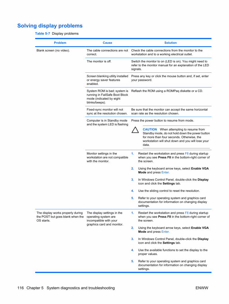
Solving display problems Table 5-7 Display problems
Problem Cause Solution
Blank screen (no video). The cable connections are notcorrect.
Check the cable connections from the monitor to theworkstation and to a working electrical outlet.
The monitor is off. Switch the monitor to on (LED is on). You might need torefer to the monitor manual for an explanation of the LEDsignals.
Screen blanking utility installedor energy saver featuresenabled.
Press any key or click the mouse button and, if set, enteryour password.
System ROM is bad; system isrunning in FailSafe Boot Blockmode (indicated by eightblinks/beeps).
Reflash the ROM using a ROMPaq diskette or a CD.
Fixed-sync monitor will notsync at the resolution chosen.
Be sure that the monitor can accept the same horizontalscan rate as the resolution chosen.
Computer is in Standby modeand the system LED is flashing
Press the power button to resume from mode.
CAUTION When attempting to resume fromStandby mode, do not hold down the power buttonfor more than four seconds. Otherwise, theworkstation will shut down and you will lose yourdata.
Monitor settings in theworkstation are not compatiblewith the monitor.
1. Restart the workstation and press F8 during startupwhen you see Press F8 in the bottom-right corner ofthe screen.
2. Using the keyboard arrow keys, select Enable VGAMode and press Enter.
3. In Windows Control Panel, double-click the Displayicon and click the Settings tab.
4. Use the sliding control to reset the resolution.
5. Refer to your operating system and graphics carddocumentation for information on changing displaysettings.
The display works properly duringthe POST but goes blank when theOS starts.
The display settings in theoperating system areincompatible with yourgraphics card and monitor.
1. Restart the workstation and press F8 during startupwhen you see Press F8 in the bottom-right corner ofthe screen.
2. Using the keyboard arrow keys, select Enable VGAMode and press Enter.
3. In Windows Control Panel, double-click the Displayicon and click the Settings tab.
4. Use the available functions to set the display to theproper values.
5. Refer to your operating system and graphics carddocumentation for information on changing displaysettings.
116 Chapter 5 System diagnostics and troubleshooting ENWW

Problem Cause Solution
Power LED flashes red six times,once every second, followed by atwo second pause, and theworkstation beeps six times.
Pre-video graphics error. CAUTION Disconnect AC power from theworkstation before reseating or replacingcomponents because there is power to the systemboard even when the workstation is powereddown.
1. Ensure that the auxiliary power cable (if applicable) issecurely connected.
2. Reseat the graphics card.
3. Replace the graphics card.
4. Replace the system board.
Monitor does not function properlywhen used with energy saverfeatures.
Monitor without energy savercapabilities is being used withenergy saver featuresenabled.
Disable monitor energy saver feature.
Characters are dim. The brightness and contrastcontrols are not set properly.
Adjust the monitor brightness and contrast controls.
Cables are not properlyconnected.
Verify that the graphics cable is securely connected to thegraphics card and the monitor.
Video is blurry or requestedresolution cannot be set.
If the graphics controller wasupgraded, the correct videodrivers might not be loaded.
Install the video drivers included in the upgrade kit.
Monitor is not capable ofdisplaying requestedresolution.
Change requested resolution.
The picture is broken up, rolls,jitters, or flashes.
The monitor connections mightbe incomplete or the monitormight be incorrectly adjusted.
1. Be sure the monitor cable is securely connected to theworkstation.
2. In a two-monitor system or if another monitor is inclose proximity, be sure the monitors are notinterfering with each other’s electromagnetic field bymoving them apart.
3. Be sure that fluorescent lights or fans are not too closeto the monitor.
Monitor needs to bedegaussed.
Degauss the monitor.
Vibrating or rattling noise comingfrom inside a CRT monitor whenpowered on.
Monitor degaussing coil hasbeen activated.
None. It is normal for the degaussing coil to be activatedwhen the monitor is powered on.
Clicking noise coming from inside aCRT monitor.
Electronic relays have beenactivated inside the monitor.
None. It is normal for some monitors to make a clickingnoise when turned on and off, when going in and out ofStandby mode, and when changing resolutions.
High pitched noise coming frominside a flat panel monitor.
Brightness and contrastsettings are too high.
Lower brightness and contrast settings.
Table 5-7 Display problems (continued)
ENWW Troubleshooting scenarios and solutions 117

Problem Cause Solution
Fuzzy focus; streaking, ghosting,or shadowing effects; horizontalscrolling lines; faint vertical bars; orunable to center the picture on thescreen. (Flat panel monitors usingan analog VGA input connectiononly.)
Flat panel monitor’s internaldigital conversion circuitsmight be unable to correctlyinterpret the outputsynchronization of thegraphics card.
1. Select the monitor’s Auto-Adjustment option in themonitor’s on-screen display menu.
2. See the HP Support website and check for an updateddisplay driver.
3. Manually synchronize the Clock and Clock Phase on-screen display functions. Download the appropriateutility from the HP website to assist with thesynchronization.
Certain typed symbols do notappear correct.
The font you are using doesnot support that particularsymbol.
Use the Character Map to locate the and select theappropriate symbol. Click Start>All Programs>Accessories>System Tools>Character Map. You cancopy the symbol from the Character Map into a document.
Table 5-7 Display problems (continued)
118 Chapter 5 System diagnostics and troubleshooting ENWW

Solving audio problems Table 5-8 Audio problems
Problem Cause Solution
Sound does not come out of thespeaker or headphones.
Software volume control isturned down.
Double-click the Speaker icon on the taskbar and use thevolume slider to adjust the volume.
The external speakers are notturned on.
Turn on the external speakers.
External speakers are pluggedinto the wrong audio jack.
See the sound card documentation for proper speakerconnection.
Audio cable not connected. Connect audio cable between CD or DVD-ROM drive andthe system board.
Digital CD audio isnot enabled.
Enable digital CD audio:
1. From the Control Panel, select System.
2. On the Hardware tab, click Device Manager.
3. Right-click the CD/DVD device and selectProperties.
4. On the Properties tab, be sure Enable digital CDaudio for this CD-ROM device is selected.
Headphones or devicesconnected to the line-outconnector mute the internalspeaker.
Turn on and use headphones or external speakers, ifconnected, or disconnect headphones or externalspeakers.
Volume is muted. 1. From the Control Panel program, click Sound,Speech and Audio Devices, and then click Soundsand Audio Devices.
2. Clear the Mute check box.
Computer is in Standby modeand the system LED isflashing.
Press the power button to resume from Standby mode.
CAUTION When attempting to resume fromStandby mode, do not hold down the power buttonfor more than four seconds. Otherwise, theworkstation will shut down and you will lose yourdata.
Noise or no sound comes out of thespeakers or headphones.
1. If using digital speakers that have a stereo jack andwant the system to auto-switch to digital, use a stereo-to-mono adapter to properly engage the auto-sensefeature or use the multimedia device propertiesto manually switch the audio signal from analog todigital.
2. If the headphones have a mono jack, use themultimedia device properties to switch the system toanalog out.
NOTE If you set digital as the Output Mode, the internal speaker and external analog speakers will no longer outputaudio until you switch back to an auto-sense or analog mode.
If you set analog as the Output Mode, external digital speakers will not function until you change the output mode backto an auto-sense or digital mode.
ENWW Troubleshooting scenarios and solutions 119

Problem Cause Solution
Sound cuts in and out. Processor resources are beingused by other openapplications.
Shut down open processor-intensive applications.
Workstation appears to be lockedup while recording audio.
The hard disk might be full. 1. Before recording, be sure there is enough free spaceon the hard disk.
2. Try recording the audio file in a compressed format.
Solving printer problemsTable 5-9 Printer problems
Problem Cause Solution
Printer does not print.Printer cableloose.
Printer is not turned on andonline.
Turn the printer on and be sure it is online.
The correct printer driver forthe application are notinstalled.
1. Install the correct printer driver for the application.
2. Try printing using the DOS command:
DIR C:\> [printer port]
where [printer port] is the address of the printerbeing used. If the printer works, reload the printerdriver.
If you are on a network, youmight not have made theconnection to the printer.
Make the proper network connections to the printer.
Printer might have failed. Run printer self-test.
Printer is out of ink/toner. Replenish ink/toner.
Printer cable loose. Check printer cable connection to non-networked, localprinter.
Printer does not turn on. The cables might not beconnected properly.
Reconnect all cables.
Printer prints garbled information. The correct printer driver is notinstalled.
Install the correct printer driver for the application.
The cables might not beconnected properly.
Reconnect all cables.
Printer memory might beoverloaded.
Reset the printer by turning it off for one minute, then turnit back on.
Printer is offline. The printer might be out ofpaper.
1. Check the paper tray and refill it if it is empty.
2. Select online.
Table 5-8 Audio problems (continued)
120 Chapter 5 System diagnostics and troubleshooting ENWW

Solving keyboard and mouse problemsTable 5-10 Keyboard and mouse problems
Problem Cause Solution
Keyboard commands and typingare not recognized by theworkstation.
Keyboard connector is notproperly connected.
1. Power off the workstation.
2. Reconnect the keyboard to the workstation andrestart the workstation.
Program in use has stoppedresponding to commands.
Shut down the workstation using the mouse and thenrestart the workstation.
Keyboard needs repairs. Replace the keyboard.
Keyboard key is stuck down. Remove any debris from the keyboard.
Workstation is in Standbymode and the system LED isflashing.
Press the power button to resume from Standby mode.
CAUTION When attempting to resume fromStandby mode, do not hold down the power buttonfor more than four seconds. Otherwise, theworkstation will shut down and you will lose yourdata.
Cursor will not move using thearrow keys on the keypad.
The Num Lock key might beon.
Press the Num Lock key. The Num Lock light should notbe on if you want to use the arrow keys. The Num Lock keycan be disabled (or enabled) in Computer Setup.
Mouse does not respond tomovement or is too slow.
Mouse connector isnot properly plugged into theback of the workstation.
1. Shut down the workstation using the keyboard.
2. Plug the mouse connector into the PS/2 or USBmouse connector in the workstation and restart theworkstation.
You need to increase mouseacceleration.
1. In Windows, click Start>Control Panel and double-click Mouse.
2. Select the Motion tab and adjust the speed.
Program in use has stoppedresponding to commands.
Shut down the workstation using the keyboard and thenrestart the workstation.
Mouse needs repairs. Replace the mouse.
Workstation is in Standbymode and system LED isflashing.
Press the power button to resume from Stand By mode.
CAUTION When attempting to resume fromStandby mode, do not hold down the power buttonfor more than four seconds. Otherwise, theworkstation will shut down and you will lose yourdata.
Mouse will only move vertically orhorizontally, or movement is jerky.
Mouse roller ball is dirty. Remove roller ball cover from the bottom of the mouse andclean it.
Solving front panel component problemsIf you are experiencing problems with one of the front panel ports, you might be able to try your devicein the corresponding port on the back side of the computer. If this does not fix the problem, or you mustuse the front panel ports, continue troubleshooting.
ENWW Troubleshooting scenarios and solutions 121

Some problems in this section are also discussed in other troubleshooting suggestions in this chapter.
Table 5-11 Front panel component problems
Problem Cause Solution
If a USB device, headphone, ormicrophone is not recognized bythe workstation.
It is not properly connected. 1. Power off the workstation.
2. Reconnect the device to the workstation and restartthe workstation.
The device does not havepower.
If the USB device requires AC power, be sure one end isconnected to the device and one end is connected to a liveoutlet.
The correct device driver is notinstalled.
1. Install the correct driver for the device.
2. You might need to reboot the workstation.
The cable from the device tothe computer does not work.
1. If possible, replace the cable.
2. Restart the workstation.
The device is not working. 1. Replace the device.
2. Restart the workstation.
If a USB, audio, and IEEE-1394devices are not working.
The internal cables might notbe connected to the systemboard or the PCI card.
1. Power off the workstation.
2. Connect the cables correctly.
A device in the IEEE-1394a port isnot responsive.
Cables of new external deviceare loose or power cables areunplugged.
Be sure that all cables are properly and securelyconnected.
The power switch on thedevice is not turned on.
Power off the workstation, and power on the externaldevice, then turn on the workstation to integrate the devicewith the workstation system.
Solving hardware installation problemsYou might need to reconfigure the workstation when you add or remove hardware, such as an additionaldiskette drive. If you install a PnP (Plug 'n Play) device, Windows XP automatically recognizes the deviceand configure the workstation. If you install a non-PnP device, you must reconfigure the workstationafter completing installation of the new hardware.
122 Chapter 5 System diagnostics and troubleshooting ENWW
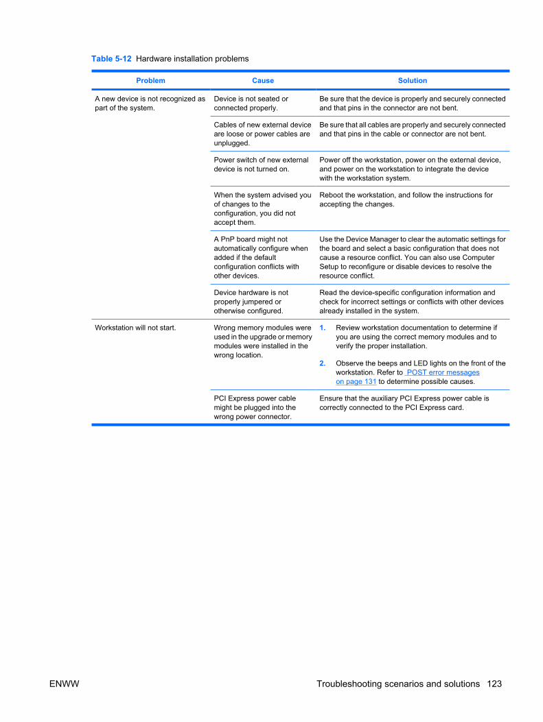
Table 5-12 Hardware installation problems
Problem Cause Solution
A new device is not recognized aspart of the system.
Device is not seated orconnected properly.
Be sure that the device is properly and securely connectedand that pins in the connector are not bent.
Cables of new external deviceare loose or power cables areunplugged.
Be sure that all cables are properly and securely connectedand that pins in the cable or connector are not bent.
Power switch of new externaldevice is not turned on.
Power off the workstation, power on the external device,and power on the workstation to integrate the devicewith the workstation system.
When the system advised youof changes to theconfiguration, you did notaccept them.
Reboot the workstation, and follow the instructions foraccepting the changes.
A PnP board might notautomatically configure whenadded if the defaultconfiguration conflicts withother devices.
Use the Device Manager to clear the automatic settings forthe board and select a basic configuration that does notcause a resource conflict. You can also use ComputerSetup to reconfigure or disable devices to resolve theresource conflict.
Device hardware is notproperly jumpered orotherwise configured.
Read the device-specific configuration information andcheck for incorrect settings or conflicts with other devicesalready installed in the system.
Workstation will not start. Wrong memory modules wereused in the upgrade or memorymodules were installed in thewrong location.
1. Review workstation documentation to determine ifyou are using the correct memory modules and toverify the proper installation.
2. Observe the beeps and LED lights on the front of theworkstation. Refer to POST error messageson page 131 to determine possible causes.
PCI Express power cablemight be plugged into thewrong power connector.
Ensure that the auxiliary PCI Express power cable iscorrectly connected to the PCI Express card.
ENWW Troubleshooting scenarios and solutions 123

Problem Cause Solution
Power LED flashes red five times,once every second, followed by atwo second pause, and theworkstation beeps five times.
Memory is installed incorrectlyor is bad.
CAUTION Disconnect AC power from theworkstation before reseating or replacingcomponents because there is power to the systemboard even when the workstation is powereddown.
1. Ensure DIMMs are loaded in the correct slots.
2. Reseat DIMMs.
3. Replace DIMMs one at a time to isolate the faultymodule.
4. Replace third-party memory with HP memory.
5. Replace the system board.
Power LED flashes red six times,once every second, followed by atwo second pause, and theworkstation beeps six times.
Video card is not seatedproperly or is bad, or systemboard is bad.
CAUTION Disconnect AC power from theworkstation before reseating or replacingcomponents because there is power to the systemboard even when the workstation is powereddown.
1. Ensure that auxiliary power cable is connectedcorrectly, if applicable.
2. Reseat the graphics card.
3. Replace the graphics card.
4. Replace the system board.
Solving network problems These guidelines do not discuss the process of debugging the network cabling.
Table 5-13 Network problems
Problem Cause Solution
Wake-on-LAN feature is notfunctioning.
Wake-on-LAN is not enabled. Use the Network control application to enable Wake-on-LAN.
Network driver does not detectnetwork controller.
Network controller is disabled. Run Computer Setup and enable network controller.
Incorrect network driver. Check the network controller documentation for thecorrect driver, or obtain the latest driver from themanufacturer’s website.
Network status link light does notturn on or it never flashes.
The network status light shouldflash when there is networkactivity.
No active network is detected. Check cabling and network equipment for properconnection.
Network controller is not set upproperly.
Use the network control application to verify that thedevice is working properly.
Network driver is not properlyloaded.
Reinstall network drivers.
System cannot auto-sense thenetwork.
Disable auto-sensing capabilities and force the systeminto the correct operating mode.
Table 5-12 Hardware installation problems (continued)
124 Chapter 5 System diagnostics and troubleshooting ENWW

Problem Cause Solution
Diagnostics reports a failure. The cable is not securelyconnected.
Be sure that both ends of the data cable are securelyconnected.
The cable is attached to theincorrect connector.
Be sure that the cable is attached to the correct connector.
There is a problem with the cableor a device at the other end of thecable.
Be sure that the cable and device at the other end areoperating correctly.
Network controller interrupt isshared with an expansion board.
Under the Computer Setup Advanced menu, change theresource settings for the board.
The network controlleris defective.
CAUTION Disconnect AC power from theworkstation before reseating or replacingcomponents because there is power to thesystem board even when the workstation ispowered down.
Replace the NIC.
Diagnostics passes, but theworkstation does notcommunicate with the network.
Network drivers are not loaded, ordriver parameters do not matchcurrent configuration.
1. Be sure the network drivers are loaded and that thedriver parameters match the configuration of thenetwork controller.
2. Be sure the correct network client and protocol isinstalled.
The network controller is notconfigured for this workstation.
Select the Network icon in the Control Panel andconfigure the network controller.
Network controller stoppedworking when an expansionboard was added to theworkstation.
Network controller interrupt isshared with an expansion board.
Under the Computer Setup Advanced menu, change theresource settings for the board.
The network controller requiresdrivers.
Verify that the drivers were not accidentally deleted whenthe drivers for a new expansion board were installed.
The expansion board installed is aNetwork Interface Card (NIC) andconflicts with the embedded NIC.
Under the Computer Setup Advanced menu, change theresource settings for the board.
Network controller stops workingwithout apparent cause.
The files containing the networkdrivers are corrupted.
Reinstall the network drivers, using the Restore Plus! CD.
The cable is not securelyconnected.
Be sure that both ends of the cable are securely attachedto the correct devices.
The network controller isdefective.
CAUTION Disconnect AC power from theworkstation before reseating or replacingcomponents because there is power to thesystem board even when the workstation ispowered down.
Replace the NIC.
New network card will not boot. New network card might bedefective or might not meetindustry-standard specifications.
Install a working, industry-standard NIC, or change theboot sequence to boot from another source.
Table 5-13 Network problems (continued)
ENWW Troubleshooting scenarios and solutions 125

Problem Cause Solution
Cannot connect to networkserver when attempting RemoteSystem Installation.
The network controller is notconfigured properly.
Verify Network Connectivity, that a DHCP Server ispresent, and that the Remote System Installation Servercontains the NIC drivers for your NIC.
System setup utility reportsunprogrammed EEPROM.
Unprogrammed EEPROM. Flash the ROM.
Solving memory problems
CAUTION For those systems that support ECC memory, HP does not support mixing ECC andnon-ECC memory. Otherwise, the system will not boot the operating system.
Table 5-14 Memory problems
Problem Cause Solution
System will not boot or does notfunction properly after installingadditional memory modules.
Memory module is not thecorrect type or speed, or thenew memory module is notseated properly.
Replace module with the correct industry-standard devicefor the workstation.
Out of memory error. Memory configuration mightnot be set up correctly.
Use the Device Manager to check memory configuration.
You have run out of memory torun the application.
Check the application documentation to determine thememory requirements, or add more memory.
Memory count during POST iswrong.
The memory modules mightnot be installed correctly.
Check that the memory modules have been installedcorrectly and that proper modules are used.
Insufficient memory error duringoperation.
Too many Terminate and StayResident programs (TSRs) areinstalled.
Delete any TSRs that you do not need.
You have run out of memoryfor the application.
Check the memory requirements for the application or addmore memory to the workstation.
Power LED flashes red 5 times,once every second, followed by a2-second pause, and theworkstation beeps 5 times.
Memory is installed incorrectlyor is bad.
CAUTION Disconnect AC power from theworkstation before reseating or replacingcomponents because there is power to the systemboard even when the workstation is powereddown.
1. Ensure DIMMs are loaded in the correct slots.
2. Reseat DIMMs.
3. Replace DIMMs one at a time to isolate the faultymodule.
4. Replace third-party memory with HP memory.
5. Replace the system board.
A total of 4 GB of RAM is installed,yet the 32–bit OS only recognizes≈ 3 GB.
A 32–bit OS is limited by 4 GBof address space, and some ofthe space is used by I/Odevices.
Use a video card that uses less on-board memory.
Table 5-13 Network problems (continued)
126 Chapter 5 System diagnostics and troubleshooting ENWW

Solving processor problems Table 5-15 Processor problems
Problem Cause Solution
Poor performance is experienced. Processor is hot. 1. Be sure the airflow to the workstation is not blocked.
2. Be sure the fans are connected and working properly(some fans only operate when needed).
3. Be sure the CPU heatsink is installed properly.
Power LED is red and stays on. Processor is not seatedproperly or not installed.
CAUTION Disconnect AC power from theworkstation before reseating or replacingcomponents because there is power to the systemboard even when the workstation is powereddown.
1. Check to see that the processor is present.
2. Reseat the processor.
Solving CD-ROM and DVD problems Table 5-16 CD-ROM and DVD problems
Problem Cause Solution
System will not boot from CD-ROMor DVD drive.
The CD-ROM or DVD boot isnot enabled through theComputer Setup utility.
Run the Computer Setup utility and enable booting toremovable media and verify boot order settings.
Non-bootable CD/DVD indrive.
Place a bootable CD/DVD in the drive.
CD-ROM or DVD devices are notdetected or driver is not loaded.
Drive is not connected properlyor not properly configured.
1. Reconnect power and data cables to the drive.
2. Install correct device driver.
Movie will not play in the DVD drive. Movie might be regionalizedfor a different country.
See the documentation that came with the DVD drive.
Decoder software is notinstalled.
Install decoder software.
Cannot eject compact disc (tray-load unit).
Disc not properly seated in thedrive.
1. Power off the workstation, and insert a thin metal rodinto the emergency eject hole and push firmly.
2. Slowly pull the tray out from the drive until the tray isfully extended, and remove the disc.
ENWW Troubleshooting scenarios and solutions 127

Problem Cause Solution
CD-ROM, CD-RW, DVD-ROM, orDVD-R/RW drive cannot read adisc or takes too long to start.
Disc has been inserted upsidedown.
Reinsert the disc with the label facing up.
The DVD-ROM drive takeslonger to start because it has todetermine the type of mediaplayed, such as audio or video.
Wait at least 30 seconds to let the DVD-ROM drivedetermine the type of media being played. If the disc stilldoes not start, read the other solutions listed for this topic.
CD or DVD disc is dirty. Clean CD or DVD with a CD cleaning kit.
Windows does not detect theCD-ROM or DVD-ROM drive.
1. Use Device Manager to remove or uninstall thedevice in question.
2. Restart the workstation and allow Windows to detectthe device.
Recording audio CDs is difficult orimpossible.
Wrong or poor quality mediatype.
1. Try using a slower recording speed.
2. Verify that you are using the correct media for thedrive.
3. Try a different brand of media. Quality varies widelybetween manufacturers.
Table 5-16 CD-ROM and DVD problems (continued)
128 Chapter 5 System diagnostics and troubleshooting ENWW

Solving Internet access problems Table 5-17 Internet access problems
Problem Cause Solution
Unable to connect to the Internet. Internet Service Provider (ISP)account is not set up properly.
Verify Internet settings or contact the ISP for assistance.
Modem is not set up properly. Reconnect the modem. Verify the connections are correctusing the quick setup documentation.
Web browser is not set upproperly.
Verify that the web browser is installed and set up to workwith your ISP.
Cable/ DSL modem is notplugged in.
Plug in cable/DSL modem. You should see a “power” LEDlight on the front of the cable/DSL modem.
The network cable isdisconnected.
Connect the network cable between the cable modem andthe workstation RJ-45 connector. If the connection works,the PC LED light on the front of the cable/DSL modem willbe on.
Cable/DSL service is notavailable or has beeninterrupted due to badweather.
Try connecting to the Internet at a later time or contact yourISP. (If the cable/DSL service is connected, the “cable” LEDlight on the front of the cable/DSL modem will be on.)
The CAT5 10/100/1000 cableis disconnected.
Connect the CAT5 10/100 cable between the cable modemand the workstations’s RJ-45 connector. (If the connectionis good, the “PC” LED light on the front of the cable/DSLmodem will be on.)
IP address is not configuredproperly.
Contact the ISP for the correct IP address.
Cookies are corrupted. 1. Select Start>Control Panel.
2. Double-click Internet Options.
3. On the General tab, click Delete Cookies.
Cannot automatically launchInternet programs.
You must log on to the ISPbefore some programs willstart.
Log on to the ISP and launch the desired program.
Internet takes too long to downloadwebsites.
Modem is not set up properly. Verify that the correct modem speed and COM port areselected.
1. Select Start>Control Panel.
2. Double-click System.
3. Click the Hardware tab.
4. In the Device Manager area, click Device Manager.
5. Double-click Ports (COM & LPT).
6. Right-click the COM port your modem uses, thenclick Properties.
7. Under Device status, verify that the modem is workingproperly.
ENWW Troubleshooting scenarios and solutions 129

Problem Cause Solution
8. Under Device usage, verify the modem is enabled.
9. If there are further problems, click Troubleshoot andfollow the on-screen instructions.
Table 5-17 Internet access problems (continued)
130 Chapter 5 System diagnostics and troubleshooting ENWW

POST error messagesPOST is a program run at startup that initializes and runs some tests on installed hardware. An audibleand/or visual message occurs if the POST encounters a problem. POST checks the following items toensure that the workstation system is functioning properly:
● Keyboard
● Memory modules
● Diskette drives
● All SATA, IDE, and SAS mass storage devices
● Processors
● Controllers
NOTE If the Power-On Password is set, a key icon appears on the screen while POST isrunning. You must enter the password before continuing.
Table 5-18 POST error messages
Screen Message Probable Cause Recommended Action
101–Option ROM Error. Plug-in card ROM checksum. Update the ROM on the card.
102–System Board Failure DMA, timers. CAUTION Disconnect AC power from theworkstation before reseating or replacingcomponents because there is power to thesystem board even when the workstation ispowered down.
1. Clear CMOS by pressing the Clear CMOS buttonon the system board.
2. Remove expansion boards.
3. Replace the system board.
103–System Board Failure DMA, timers. CAUTION Disconnect AC power from theworkstation before reseating or replacingcomponents because there is power to thesystem board even when the workstation ispowered down.
1. Clear CMOS by pressing the Clear CMOS buttonon the system board.
2. Remove expansion boards.
3. Replace the system board.
110–Out of Memory Space forOption ROMs
Option ROM for a device was unableto run due to memory constraints.
Remove expansion boards and disable unneededdevices from I/O>Onboard Devices orStorage>Storage Options. Run Computer Setup(F10).
ENWW POST error messages 131

Screen Message Probable Cause Recommended Action
162–System Options Not Set Your system configuration haschanged since your last boot, in whichcase press F1. Or, a loss of power tothe Real Time clock has occurred.
1. Run Computer Setup (F10).
2. Set the date and time under Windows ControlPanel or in the F10 Setup menu.
3. If the problem persists, replace the RTC battery.
163–Time and Date Not Set Invalid time or date in configurationmemory.
RTC (real-time clock) battery mightneed to be replaced.
1. Set the date and time under Control Panel or inF10 Setup, depending on the operating system.
2. If the problem persists, replace the RTC battery.
164–Memory Size Error The system memory size has changedsince the last boot.
1. Pressing F1 will record the configuration.
2. If the problem persists, be sure memory modules(if any) are installed correctly.
3. If third-party memory has been added, test usingHP memory only.
4. Verify proper memory module type.
201–Memory Error The memory test performed duringstartup failed.
CAUTION Disconnect AC power from theworkstation before reseating or replacingcomponents because there is power to thesystem board even when the workstation ispowered down.
1. Run Computer Setup (F10 Setup) or Windowsutilities.
2. Ensure that memory modules are installedcorrectly.
3. Verify proper memory module type.
4. If third-party memory has been added, test usingHP memory only.
5. Remove and replace memory modules one at atime to isolate faulty module.
6. Replace the faulty memory modules.
7. If error persists after replacing memory modules,replace the system board.
207–ECC Corrected Single BitErrors in DIMM slot(s)
Corrected ECC error(s) detected. CAUTION Disconnect AC power from theworkstation before reseating or replacingcomponents because there is power to thesystem board even when the workstation ispowered down.
1. Verify proper memory module type.
2. Verify 3rd party/HP memory.
3. Try another memory socket.
4. Replace memory module if problem persists.
Table 5-18 POST error messages (continued)
132 Chapter 5 System diagnostics and troubleshooting ENWW

Screen Message Probable Cause Recommended Action
211–Memory warningcondition detected
An unknown issue with one of theDIMMs has been detected.
CAUTION Disconnect AC power from theworkstation before reseating or replacingcomponents because there is power to thesystem board even when the workstation ispowered down.
1. Verify proper memory module type.
2. Try another memory socket.
3. Replace memory module if problem persists.
213–Incompatible ECCMemory Module in memorySocket(s)
The memory modules in the systemare either not all ECC, or not all non-ECC. This could also be causedbecause the DIMM is missing criticalSPD information.
CAUTION Disconnect AC power from theworkstation before reseating or replacingcomponents because there is power to thesystem board even when the workstation ispowered down.
1. Verify that all memory modules are ECC or non-ECC.
2. Replace memory module if problem persists.
214–DIMM ConfigurationWarning
DIMMs not installed correctly (notpaired correctly).
CAUTION Disconnect AC power from theworkstation before reseating or replacingcomponents because there is power to thesystem board even when the workstation ispowered down.
Refer to Memory on page 69 for the correct memoryconfigurations and reseat the DIMMs accordingly.
215–Cannot InterleaveUnequal Memory Nodes
Memory node interleave enabled butmemory on CPU0 is unequal with thememory on CPU1.
CAUTION Disconnect AC power from theworkstation before reseating or replacingcomponents because there is power to thesystem board even when the workstation ispowered down.
1. Reconfigure memory in both nodes equally.
2. Disable memory node interleave.
301–Keyboard Error Keyboard failure. 1. Reconnect keyboard with workstationpowered off.
2. Check the connector for bent or missing pins.
3. Be sure that none of the keys are pressed or stuck.
4. Replace keyboard.
Table 5-18 POST error messages (continued)
ENWW POST error messages 133

Screen Message Probable Cause Recommended Action
303–Keyboard Controller Error I/O board keyboard controller. CAUTION Disconnect AC power from theworkstation before reseating or replacingcomponents because there is power to thesystem board even when the workstation ispowered down.
1. Reconnect keyboard with workstationpowered off.
2. Replace the system board.
304–Keyboard or System UnitError
Keyboard failure. CAUTION Disconnect AC power from theworkstation before reseating or replacingcomponents because there is power to thesystem board even when the workstation ispowered down.
1. Reconnect the keyboard to the powered-offworkstation.
2. Be sure that none of the keys are pressed or stuck.
3. Replace keyboard.
4. Replace system board.
510–Splash Screen ImageCorrupted
Splash Screen image has errors. Restore BIOS.
511–CPU Fan Not Detected Fan is not connected or it might havemalfunctioned.
1. Reseat fan cable.
2. Reseat the fan.
3. Replace the fan.
512–PCI 1 Fan Not Detected Fan is not connected or it might havemalfunctioned.
CAUTION Disconnect AC power from theworkstation before reseating or replacingcomponents because there is power to thesystem board even when the workstation ispowered down.
1. Reseat PCI fan cable.
2. Replace PC1 fan.
513–Chassis Fan or MemoryFan Not Detected
Memory or system fan is notconnected or it might havemalfunctioned.
CAUTION Disconnect AC power from theworkstation before reseating or replacingcomponents because there is power to thesystem board even when the workstation ispowered down.
1. Reseat memory or system fan connector.
2. Replace memory or system fan.
516–Processors Do Not Havethe Same Frequency OperatingRange
Installed processors operate atdifferent frequencies.
Replace a processor so that both operate at the samefrequency.
Table 5-18 POST error messages (continued)
134 Chapter 5 System diagnostics and troubleshooting ENWW

Screen Message Probable Cause Recommended Action
516–Processors Do Not Havethe Same Frequency OperatingRange
Installed processors operate atdifferent frequencies.
Replace a processor so that both operate at the samefrequency.
517–Front IEEE 1394 NotConnected
Front IEEE 1394 port is not connected. CAUTION Disconnect AC power from theworkstation before reseating or replacingcomponents because there is power to thesystem board even when the workstation ispowered down.
1. Connect IEEE 1394 cable to system board.
2. Replace system board.
518–Detected invalid MACaddress
Workstation has invalid MAC address. CAUTION Disconnect AC power from theworkstation before reseating or replacingcomponents because there is power to thesystem board even when the workstation ispowered down.
● Verify correct MAC address. If incorrect, replacesystem board.
601–Diskette Controller Error Diskette controller circuitry or diskettedrive circuitry incorrect.
CAUTION Disconnect AC power from theworkstation before reseating or replacingcomponents because there is power to thesystem board even when the workstation ispowered down.
1. Run Computer Setup (F10 Setup).
2. Ensure that cables are connected correctly.
3. Check and replace cables.
4. Clear CMOS by pressing the Clear CMOS buttonon the system board.
5. Replace diskette drive.
6. Replace the system board.
605–Diskette Drive Type Error Mismatch in drive type. 1. Check drive cables.
2. Run Computer Setup (F10 Setup).
3. Disconnect any other diskette controller devices(tape drives).
4. Clear CMOS by pressing the Clear CMOS buttonon the system board.
5. Replace diskette drive.
710–NET Watchdog TimerExpired from Last Boot
System hung during last boot. Press F1 to boot.
912–Computer Cover HasBeen Removed Since LastSystem Start Up
System has been opened since lastboot.
No action required.
Table 5-18 POST error messages (continued)
ENWW POST error messages 135

Screen Message Probable Cause Recommended Action
914–Hood Lock Coil is notConnected
Hood lock mechanism is missing ornot connected.
1. Reconnect or replace the hood lockingmechanism.
2. Reseat or replace the hood locking mechanismcable.
915–Fan Power from PowerSupply Not Connected
The fan power cable is not connected,or the power supply is bad.
CAUTION Disconnect AC power from theworkstation before reseating or replacingcomponents because there is power to thesystem board even when the workstation ispowered down.
1. Verify that all power supply cables are connected.
2. Replace the power supply.
916–Power Button NotConnected
The power button is not connected. CAUTION Disconnect AC power from theworkstation before reseating or replacingcomponents because there is power to thesystem board even when the workstation ispowered down.
Connect the power button.
917–Front Audio NotConnected
The front audio cable is not connected. CAUTION Disconnect AC power from theworkstation before reseating or replacingcomponents because there is power to thesystem board even when the workstation ispowered down.
Connect the front audio cable.
918–Front USB Not Connected Front USB is not connected. CAUTION Disconnect AC power from theworkstation before reseating or replacingcomponents because there is power to thesystem board even when the workstation ispowered down.
Connect the front USB cable.
921–Device in PCI ExpressSlot Failed to Initialize
A PCI Express card was detected inone of the slots, but failed to initializeproperly.
CAUTION Disconnect AC power from theworkstation before reseating or replacingcomponents because there is power to thesystem board even when the workstation ispowered down.
Reseat all PCI Express cards. If this failure occurredafter inserting a new card, there could be a problem withthat card.
922–Fatal error on slot # Fatal error occurred in the designatedslot.
CAUTION Disconnect AC power from theworkstation before reseating or replacingcomponents because there is power to thesystem board even when the workstation ispowered down.
Try moving card to a different slot. If the problempersists, try replacing the card.
Table 5-18 POST error messages (continued)
136 Chapter 5 System diagnostics and troubleshooting ENWW
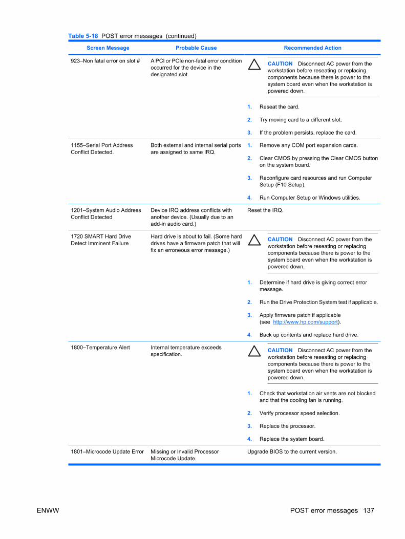
Screen Message Probable Cause Recommended Action
923–Non fatal error on slot # A PCI or PCIe non-fatal error conditionoccurred for the device in thedesignated slot.
CAUTION Disconnect AC power from theworkstation before reseating or replacingcomponents because there is power to thesystem board even when the workstation ispowered down.
1. Reseat the card.
2. Try moving card to a different slot.
3. If the problem persists, replace the card.
1155–Serial Port AddressConflict Detected.
Both external and internal serial portsare assigned to same IRQ.
1. Remove any COM port expansion cards.
2. Clear CMOS by pressing the Clear CMOS buttonon the system board.
3. Reconfigure card resources and run ComputerSetup (F10 Setup).
4. Run Computer Setup or Windows utilities.
1201–System Audio AddressConflict Detected
Device IRQ address conflicts withanother device. (Usually due to anadd-in audio card.)
Reset the IRQ.
1720 SMART Hard DriveDetect Imminent Failure
Hard drive is about to fail. (Some harddrives have a firmware patch that willfix an erroneous error message.)
CAUTION Disconnect AC power from theworkstation before reseating or replacingcomponents because there is power to thesystem board even when the workstation ispowered down.
1. Determine if hard drive is giving correct errormessage.
2. Run the Drive Protection System test if applicable.
3. Apply firmware patch if applicable(see http://www.hp.com/support).
4. Back up contents and replace hard drive.
1800–Temperature Alert Internal temperature exceedsspecification.
CAUTION Disconnect AC power from theworkstation before reseating or replacingcomponents because there is power to thesystem board even when the workstation ispowered down.
1. Check that workstation air vents are not blockedand that the cooling fan is running.
2. Verify processor speed selection.
3. Replace the processor.
4. Replace the system board.
1801–Microcode Update Error Missing or Invalid ProcessorMicrocode Update.
Upgrade BIOS to the current version.
Table 5-18 POST error messages (continued)
ENWW POST error messages 137

Screen Message Probable Cause Recommended Action
1802–CPU0 Not Supported The system board does not supportthe processor.
CAUTION Disconnect AC power from theworkstation before reseating or replacingcomponents because there is power to thesystem board even when the workstation ispowered down.
Replace the processor with a compatible one.
1803–CPU1 Not Supported The system board does not supportthe processor.
CAUTION Disconnect AC power from theworkstation before reseating or replacingcomponents because there is power to thesystem board even when the workstation ispowered down.
Replace the processor with a compatible one.
1805–CPU Bypass Board isMissing
Bypass board not detected on single-processor system.
CAUTION Disconnect AC power from theworkstation before reseating or replacingcomponents because there is power to thesystem board even when the workstation ispowered down.
Install bypass board or install second processor.
Invalid Electronic SerialNumber
Electronic serial number has becomecorrupted.
● Run Computer Setup. Enter the serial numberunder Security>System IDs, and save thechanges.
Table 5-18 POST error messages (continued)
138 Chapter 5 System diagnostics and troubleshooting ENWW

A SAS devices
ENWW 139

Supported SAS RAID configurationsThe following RAID configurations are supported on the HP xw9400 Workstation.
NOTE This section does not apply to configuring RAID in the Linux environment. For RAID inthe Linux environment, configure SW RAID configurations as provided by Red Hat EnterpriseLinux.
● Up to 5 internal or 8 external SAS hard disk drives/JBOD.
● External connections require optional internal-to-external cable
● SAS drives require SATA to SAS data and power converter
● LSI MyStorage Utility for Windows
● RAID 0 (IS) – Striped disk array
● Two drives minimum
● Improved I/O performance
● No fault tolerance
● RAID 1 (IM) — Mirrored disk array
● Two drives
● Improved read performance
● 100% redundancy
● Can recover from single drive failure
● RAID 1E (IME)
● Three drives minimum
● Can be an odd number of drives
● Can always recover from a single drive failure, and in some cases, recover from two drivefailures
140 Appendix A SAS devices ENWW

SAS RAID 0 (IS) configurationFollow the steps below to configure an Integrated Striped (IS) volume with the BIOS-based configurationutility. The configuration procedure assumes that the system already has the required disks attached tothe SAS/SATA ports.
1. At the BIOS splash screen, press any key to view option ROM messages.
2. Press Ctrl-C at the prompt Press Ctrl-C to Start LSI Logic Configuration Utility to start the utility.
3. On the Adapter List screen of the LSI Logic Config Utility, use the arrow keys to highlight an adapter(SAS1068e), then press Enter.
4. On the Adapter Properties screen use the arrow keys to highlight RAID Properties, then pressEnter.
5. In the Select New Array Type-SAS1068e screen, use the arrow keys to highlight Create ISVolume, then press Enter.
6. In the Create New Array-SAS1068e screen, use the arrow keys to select the first disk for the CreateIS volume. Then use the arrow keys to move to the Raid Disk column for this disk, and pressthe SPACE, +, or - key to select Yes as the value for this column. If there is existing data on thedisk, a message displays warning you that data on the disk is lost when the striped volume iscreated. Press the M key to migrate, or the D key to delete the data on the drive.
NOTE An xw9400 chassis supports up to 5 internal hard disk drives. Using external cables,up to three additional drives can be connected via individual external drives for a total ofeight drives. Up to 128 devices can be supported via connection to a JBOD.
7. Repeat the previous step to select up to four more disks for the striped volume.
8. Press the C key to create the array once all drives have been chosen.
9. Use the arrow keys to select Save Changes then Exit this Menu, then press Enter.
10. Press Esc-Esc. Use the arrow keys to highlight Exit the Configuration Utility and Reboot, thenpress Enter.
11. If necessary, change the boot order in system BIOS to obtain the correct boot device.
ENWW SAS RAID 0 (IS) configuration 141

SAS RAID 1 (IM) configurationFollow the steps below to configure an Integrated Mirroring (IM) volume with the BIOS-basedconfiguration utility. The configuration procedure assumes that the system already has the requireddisks attached to the SAS/SATA ports.
1. At the BIOS splash screen, press any key to view option ROM messages.
2. Press Ctrl-C at the Press Ctrl-C to Start LSI Logic Configuration Utility prompt to enter theconfiguration utility.
3. On the Adapter List screen of the LSI Logic Config Utility, use the arrow keys to highlight an adapter(SAS1068e), then press Enter.
4. On the Adapter Properties-SAS1068e screen use the arrow keys to highlight RAID Properties,then press Enter.
5. On the Select New Array Type screen, use the arrow keys to highlight the Create Volume IMvolume, then press Enter.
6. In the Create New Array-SAS1068e screen, use the arrow keys to select the primary disk for theIM volume (the disk with the data you want to mirror.) Use the arrow keys to move to the Raid Diskcolumn for this disk and use the Space, +, or - key to select Yes as the value. If there is existingdata on the disk, a message appears warning you that data on the disk is lost when the disk isused in an IM array.
Press the M key to keep the existing data and migrate to an IM array. Synchronization of the diskoccurs. Press he D key to overwrite the existing data and create a new IM array. No synchronizationis performed.
CAUTION All data on all disks in the array is deleted if D is selected.
After selecting M or D, the Drive Status changes to Primary for the initial drive selected.
7. Use the arrow keys to select the secondary (mirrored) disk for the IM volume. Use the SPACE,+, or - key to select Yes as the value for the Array Disk column. When the second drive selectedin RAID Disk is set to Yes, Drive Status changes to Secondary.
● [Optional] Use the arrow keys to select a hot spare disk for the IM volume. Use SPACE, +,or - to select Yes as the value in the Hot Spr column.
8. When you have completed selection of drives and hot spares for the IM array, press C to createthe array.
9. Use the arrow keys to select Save Changes then Exit this Menu, then press Enter.
10. Press Esc-Esc. Use the arrow keys to highlight Exit the Configuration Utility and Reboot, andpress Enter.
11. If necessary, change the boot order in system BIOS to obtain the correct boot device.
142 Appendix A SAS devices ENWW

SAS RAID 1E (IME) configurationFollow the steps below to configure an Integrated Mirroring Extended (IME) volume with the BIOS-basedconfiguration utility. The configuration procedure assumes that the system already has the requireddisks attached to the SAS/SATA ports.
1. At the BIOS splash screen, press any key to view option ROM messages.
2. Press Ctrl-C at the Press Ctrl-C to Start LSI Logic Configuration Utility prompt to enter theconfiguration utility.
3. On the Adapter List screen of the LSI Logic Config Utility, use the arrow keys to highlight an adapter(SAS1068e), then press Enter.
4. On the Adapter Properties-SAS1068e screen use the arrow keys to select RAID Properties, thenpress Enter.
5. On the Select New Array Type-SAS1068e screen, use the arrow keys to highlight Create IMEVolume, then press Enter.
● In the Create New Array-SAS1068e screen, use the arrow keys to select the first disk for theIME volume. Use the arrow keys to move to the RAID Disk column for this disk, and usethe SPACE, +, or - key to select Yes as the value.
6. Use the arrow keys to select the next disk for the IME volume. Use the SPACE, +, or - key toselect Yes as the value for the RAID Disk column.
7. Repeat the previous steps to select up to four more disks for the IME volume. If you want toconfigure a hot spare disk for the volume, you can only select up to three more disks.
● [Optional] Use the arrow keys to select a Hotspare disk for the IME volume. Use SPACE, +,and - to select Yes as the value in the Hot Spr column.
8. When you have completed selection of the drives and hot spares for the IME array, press C tocreate the array.
9. Use the arrow keys to highlight Save Changes Then Exit this Menu, and press Enter.
10. Press Esc-Esc. Use the arrow keys to highlight Exit the Configuration Utility and Reboot, andpress Enter.
11. If necessary, change the boot order in system BIOS to obtain the correct boot device.
ENWW SAS RAID 1E (IME) configuration 143

Changing boot orderIf the RAID array will be a data array, the disk drive with the operating system must appear higher in theboot order. If the RAID array will be the operating system drive, it should appear higher in the boot order.
To change the boot order:
1. Press F10 to call up the BIOS Setup utility when booting the system.
2. If first boot, select the desired language and press Enter. English is the default.
3. Use the arrow keys to highlight Storage>Boot Order, and press Enter.
4. In the Hard Drive section device names are listed in order of boot. Use the arrow keys to move thecursor to the device that you want to move. Press Enter to highlight the device.
5. Use the up/down arrow keys to move the device to the desired order location. Press Enter to un-highlight the device.
6. Press F10 to save changes.
7. Use the arrow keys to highlight File>Save Changes and Exit. Press Enter, then F10.
144 Appendix A SAS devices ENWW

B SATA devices
This appendix describes how to use the NVIDIA MediaShield utility to set up and manage SATA RAIDvolumes.
The SATA RAID option must be enabled in BIOS and the SATA drives must be attached to theworkstation ports to configure them into a RAID array.
Attach the required number of SATA HDDs for the desired RAID level:
● RAID 0–two to six HDDs–data is striped across drives for performance
● RAID 1–two HDDs–data is mirrored on two drives for security
● RAID 5–three to six HDDs–data is striped across drives with parity for performance with security
● RAID 10–four to six HDDs–data is mirrored and striped across all drives for security and someperformance
ENWW 145

Enable SATA RAID option in BIOSTo enable the SATA RAID option in BIOS:
1. During boot up, press F10 to enter the Setup menu. Entering BIOS Setup (Press F10) appearsat the bottom of the screen.
2. If first boot, select the desired language and press Enter.
3. Use the arrow keys to highlight I/O>Device Options and press Enter.
4. Use the up/down arrow keys to place the cursor next to SATA RAID. Use the left/right arrow keysto change the State to Enable.
NOTE All six ports (0–5) then indicate they are enabled. If the operating system boot driveis a non-RAID SATA drive, this port should have RAID disabled.
5. Use the up/down arrow keys to place the cursor next to the ports that are not to be included in theRAID array. Use the left/right arrow keys to change the state of each of them to Disable.
6. Press F10 when all ports have been set to the desired state.
7. Use the arrow keys to highlight File>Save Changes and Exit. Press Enter, then press F10 to savechanges.
The workstation will reboot after the changes are saved. After the workstation reboots, the BIOS displaysthe MediaShield copyright message.
146 Appendix B SATA devices ENWW

Configuring a SATA RAID arrayTo configure a SATA RAID array:
1. At the BIOS splash screen, press any key to view option ROM messages.
2. Press F6 to enter the RAID setup utility when Press F6 to enter RAID setup utility is displayed.
3. On the Define a New Array screen, RAID Mode is highlighted in blue and mirroring is set as thedefault setting. Press Enter to show the RAID modes. This mode enables control of mirroring,striping, stripe mirroring, spanning, and RAID 5.
4. Use the up/down arrow keys to highlight in red the desired RAID type, then press Enter. The desiredRAID mode will be highlighted in blue.
5. Press the Tab key to move the blue highlight to Striping Block:.
6. Use the up/down arrow keys to highlight in red the desired striping block size (4K, 8K, 16K 32K,64K, 128K or Optimal). Press Enter to select the desired size.
NOTE Optimal is the default and is generally selected. It is determined by the RAIDcontroller for best fit.
7. Press the Tab key to move the blue highlight to the Free Disks section.
NOTE All drives available for RAID are listed and the first drive is highlighted in red.
8. Use the up/down arrow keys to highlight in red the drives to be included in the RAID array.
9. Use the right arrow key to move the drive to the Array Disks section.
NOTE The left arrow key moves the red highlighted drive in the Array Disks section to theFree Disks section.
10. Press F7 to finish when all desired drives selected for the array are in the Array Disks section.
11. To clear disk data press Y, or to save disk data in the array press N.
The Array List window appears showing the created array. It contains Status, Bootable, Vendor,and Array Model Name information.
12. Press Ctrl-X to exit the utility.
ENWW Configuring a SATA RAID array 147

Changing boot orderIf the RAID array will be a data array, the disk drive with the operating system must appear higher in theboot order. If the RAID array will be the operating system drive, it should appear higher in the boot order.
To change the boot order:
1. Press F10 to call up the BIOS Setup utility when booting the system.
2. If first boot, select the desired language and press Enter. English is the default.
3. Use the arrow keys to highlight Storage>Boot Order, and press Enter.
4. In the Hard Drive section device names are listed in order of boot. Use the arrow keys to move thecursor to the device that you want to move. Press Enter to highlight the device.
5. Use the up/down arrow keys to move the device to the desired order location. Press Enter to un-highlight the device.
6. Press F10 to save changes.
7. Use the arrow keys to highlight File>Save Changes and Exit. Press Enter, then F10.
148 Appendix B SATA devices ENWW

Deleting RAID volumesUse the NVIDIA MediaShield utility to delete RAID volumes.
1. Press F6 to enter the RAID setup utility when Press F6 to enter RAID setup utility is displayed.The MediaShield Utility displays the array list. One of the arrays listed is highlighted in red.
2. Use the up/down arrow keys to highlight RAID volume to be deleted.
3. Press Enter to enter the array details. The Array Details screen shows the array details. Press Dto delete, then Y to confirm the delete.
The screen then returns to either Array List or Define a New Array.
ENWW Deleting RAID volumes 149

150 Appendix B SATA devices ENWW

C Connector pins
ENWW 151

Connector pin descriptionsEthernet connector Pin Signal
1
2
3
4
(+) Transmit Data
(-) Transmit Data
(+) Receive Data
Unused
5
6
7
8
Unused
(-) Receive Data
Unused
Unused
Serial connector Pin Signal
1
2
3
Carrier Detect
Receive Data
Transmit Data
4
5
6
Data Terminal Ready Signal
Ground
Data Set Ready
7
8
9
Request to Send
Clear to Send
Ring Indicator
USB connector Pin Signal
1
2
3
4
+5 VDC
- Data
+ Data
GND
IEEE 1394 connector Pin Signal
152 Appendix C Connector pins ENWW

1 power
2 gnd
3 tpb-
4 tpb+
5 tpa-
6 tpa+
Microphone connector (1/8 inch) Pin Signal
1 (Tip)
2 (Ring)
3 (Shield)
Audio
Power
Ground
Headphone connector (1/8 inch) Pin Signal
1 (Tip)
2 (Ring)
3 (Shield)
Audio_Left
Audio_Right
Ground
Line-in audio connector (1/8 inch) Pin Signal
1 (Tip)
2 (Ring)
3 (Shield)
Audio_In_Left
Audio_In_Right
Ground
Line-out audio connector (1/8 inch) Pin Signal
1 (Tip)
2 (Ring)
3 (Shield)
Audio_Out_Left
Audio_Out_Right
Ground
SPDIF OUT connector Pin Signal
1
2
+VDC
Ground
ENWW Connector pin descriptions 153
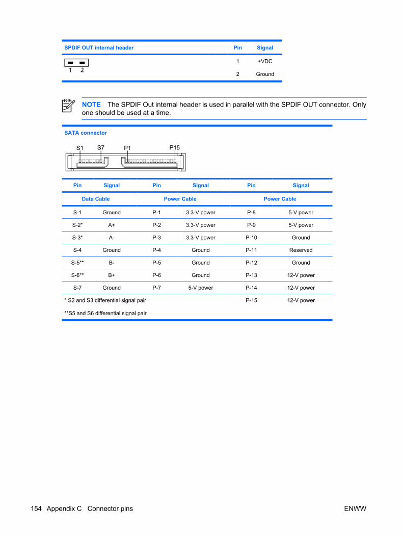
SPDIF OUT internal header Pin Signal
1
2
+VDC
Ground
NOTE The SPDIF Out internal header is used in parallel with the SPDIF OUT connector. Onlyone should be used at a time.
SATA connector
Pin Signal Pin Signal Pin Signal
Data Cable Power Cable Power Cable
S-1 Ground P-1 3.3-V power P-8 5-V power
S-2* A+ P-2 3.3-V power P-9 5-V power
S-3* A- P-3 3.3-V power P-10 Ground
S-4 Ground P-4 Ground P-11 Reserved
S-5** B- P-5 Ground P-12 Ground
S-6** B+ P-6 Ground P-13 12-V power
S-7 Ground P-7 5-V power P-14 12-V power
* S2 and S3 differential signal pair
**S5 and S6 differential signal pair
P-15 12-V power
154 Appendix C Connector pins ENWW

SAS connector
Segment Pin Backplane receptacle Plug and cablereceptacles
Primary signal segment S1 SIGNAL GROUND
S2 TP+ RP+
S3 TP- RP-
S4 SIGNAL GROUND
S5 RP- TP-
S6 RP+ TP+
S7 SIGNAL GROUND
Secondary signal segment S8 SIGNAL GROUND
S9 TS+ RS+
S10 TS- RS-
S11 SIGNAL GROUND
S12 RS- TS-
S13 RS+ TS+
S14 SIGNAL GROUND
Power segment P1 V33c
P2 V33c
P3 V33c precharge c
P4 GROUND
P5 GROUND
P6 GROUND
P7 V5c precharge c
P8 V5c
P9 V5c
P10 GROUND
P11 READY LED d
P12 GROUND
P13 V12 precharge c
P14 V12c
P15 V12c
ENWW Connector pin descriptions 155

VGA cconnector
Pin Signal Pin Signal Pin Signal
1
2
3
Red Analog
Green Analog
Blue Analog
6
7
8
GND
GND
GND
11
12
13
Monitor ID
DDC Serial Data
Horizontal Sync
4
5
Monitor ID
GND
9
10
+5V DC
GND
14
15
Vertical Sync
DDC Serial Clock
DVI connector
Pin Signal Pin Signal
1 T.M.D.S DATA 2- 16 HOT PLUG DETECT
2 T.M.D.S DATA 2+ 17 T.M.D.S DATA 0-
3 T.M.D.S DATA 2/4 SHIELD 18 T.M.D.S DATA 0+
4 T.M.D.S DATA 4- 19 T.M.D.S DATA 0/5 SHIELD
5 T.M.D.S DATA 4+ 2 0 T.M.D.S DATA 5-
6 DDC CLOCK 21 T.M.D.S DATA 5+
7 DDC DATA 22 T.M.D.S CLOCK SHIELD
8 ANALOG VERT. SYNC 23 T.M.D.S CLOCK+
9 T.M.D.S DATA 1- 24 T.M.D.S CLOCK-
10 T.M.D.S DATA 1+
11 T.M.D.S DATA 1/3 SHIELD C1 ANALOG RED
12 T.M.D.S DATA 3- C2 ANALOG GREEN
13 T.M.D.S DATA 3+ C3 ANALOG BLUE
14 +5V POWER C4 ANALOG HORZ SYNC
15 GND C5 ANALOG GROUND
156 Appendix C Connector pins ENWW

ATA/ATAPI (IDE) standard drive cable connector
Pin Signal Pin Signal Pin Signal
1
2
3
4
5
Reset
GND
DD7
DD8
DD6
15
16
17
18
19
DD1
DD14
DD0
DD15
GND
29
30
31
32
33
DMAK
GND
INTRQ
IOCS16
DA1
6
7
8
9
10
DD9
DD5
DD10
DD4
DD11
20
21
22
23
24
(Key)
DMARQ
GND
DIOW
GND
34
35
36
37
38
PDIAG (cable detect)
DA0
DA2
CS1FX
CS3FX
11
12
13
14
DD3
D12
D2
D13
25
26
27
28
DIOR
GND
IORDY
CSEL
39
40
DASP
GND
24-Pin Main power connector
1 12
13 24
1
2
3
4
5
6
7
+3.3 V
+3.3 V
GND
+5 V
GND
+5 V
GND
8
9
10
11
12
13
POK
+5 Vaux
+12V-B
+12V-B
+3.3 V
+3.3 V/+3.3 V-Rsense
14
15
16
17
18
19
20
-12 V
GND
PS_ON_L
GND
GND
GND
21
22
23
24
+5 V
+5 V/+5 V-Rsense
+5 V
GND
ENWW Connector pin descriptions 157

4-Pin power (memory system board) connector Pin Color Signal
1 BLK GND
2 BLK GND
3 BLK w/YEL stripe +12V-M
4 BLK w/YEL stripe +12V-M
8-Pin power (for CPUs and onboard regulators)connector
Pin Color Signal
5 8
41
1 BLK GND
2 BLK GND
3 BLK GND
4 BLK GND
5 Gray
BLK w/WHT stripe
+12 V CPU0 Rsense
+12 V CPU0
6 BLK w/WHT stripe +12VCPU0
7 BLK w/light bluestripe
+12VCPU1
8 BLK w/light bluestripe
+12VCPU1
NOTE The 6-pin power (auxiliary PCI Express) is only required with high-powered graphicscards.
6-Pin power (auxiliary PCI Express) Pin Color Signal
4 6
31
1 BLK w/YEL stripe +12V-G
2 BLK w/YEL stripe +12V-G
3 BLK w/YEL stripe +12V-G
4 BLK GND
5 BLK GND
6 BLK GND
158 Appendix C Connector pins ENWW

Keyboard connector Pin Signal
1
2
3
DataUnusedGround
4
5
6
+5 VDCClock
Unused
Mouse connector Pin Signal
1
2
3
DataUnusedGround
4
5
6
+5 VDCClock
Unused
ENWW Connector pin descriptions 159

160 Appendix C Connector pins ENWW

D System board designators
This appendix lists the system board designators for this system.
Designator Silkscreen Component
BAT1 BAT1 Battery retainer
E15 CRISIS RECOVERY Boot Block recovery jumper
E49 CLR PSWD Clear password jumper
J9 None Stacked RJ45/dual USB
J12 FRNT 1394 Front panel 1394a header
J14 SPDIF OUT connector
J15 None Stacked RJ45/dual USB
J20 SLOT3 PCI32/33 PCI 32–bit slot
J25 SLOT6 PCI-X x100 PCI-X slot
J26 SLOT7 PCI-X x100/133 PCI-X slot
J31 SLOT1 PCI-E x8 PCIe x8 slot
J32 SLOT5 PCI-E x16 PCIe x16 slot
J33 SLOT4 PCI-E x8 PCIe x8 slot
J34 FRNT-P Front panel connector
J41 SLOT2 PCI-E x16 PCI Express x16 slot for graphics
J68 None Stacked keyboard/mouse connector
J83 Triple stacked audio jack
J84 1394/USB IEEE 1394a/dual USB stacked connector
JP13 1-2 FORCE TO100 MHz
2-3 100/133 MHz (DEFAULT)
PCI-X bus speed select jumper*
JP16 HBA HDD LED ACTIVITY HBA HDD LED activity header
JP30 FAN DET OVR Fan detection override jumper
P1 PWR Main power connector (24-pin)
P2 PWR2 Memory power connector (4-pin)
P3 PWRCPU Processor power connector (8-pin)
ENWW 161
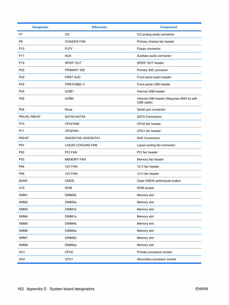
Designator Silkscreen Component
P7 CD CD analog audio connector
P8 CHASSIS FAN Primary chassis fan header
P10 FLPY Floppy connector
P11 AUX Auxiliary audio connector
P19 SPDIF OUT SPDIF OUT header
P20 PRIMARY IDE Primary IDE connector
P23 FRNT AUD Front panel audio header
P24 FRNTUSB2–3 Front panel USB header
P25 IUSB1 Internal USB header
P26 IUSB0 Internal USB header (Requires AMO kit withUSB cable)
P54 None Serial port connector
P60-63, P66-67 SATA0-SATA5 SATA Connectors
P70 CPUFAN0 CPU0 fan header
P71 CPUFAN1 CPU1 fan header
P80-87 SAS/SATA0–SAS/SATA7 SAS Connectors
P91 LIQUID COOLING FAN Liquid cooling fan connector
P92 PCI FAN PCI fan header
P93 MEMORY FAN Memory fan header
P94 12V FAN 12-V fan header
P95 12V FAN 12-V fan header
SW50 CMOS Clear CMOS switch/push button
U15 ROM ROM socket
XMM1 DIMM3b Memory slot
XMM2 DIMM3a Memory slot
XMM3 DIMM1b Memory slot
XMM4 DIMM1a Memory slot
XMM5 DIMM4b Memory slot
XMM6 DIMM4a Memory slot
XMM7 DIMM2b Memory slot
XMM8 DIMM2a Memory slot
XU1 CPU0 Primary processor socket
XU2 CPU1 Secondary processor socket
162 Appendix D System board designators ENWW

* With the jumper on pins 1 and 2, the PCI-X bus speed is 100 MHz, regardless of the card configurationin slots 6 and 7. With the jumper on pins 2 and 3 (default), the following PCI-X bus speed/cardconfiguration applies:
Card configuration Max PCI-X bus speed achieved*
One card in slot 7 only 133 MHz
One card in slot 6 only 100 MHz
Two cards, one in each slot 100 MHz
* Dependent upon card capability.
ENWW 163

164 Appendix D System board designators ENWW

E Power cord set requirements
The power cord set (flexible cord or wall plug) received with this product meets the requirements for usein the country where you purchased the equipment.
If you must obtain a power cord for a different country, purchase a power cord that is approved for usein that country.
The power cord must be rated for the product and for the voltage and current marked on the product’selectrical ratings label. The voltage and current rating of the cord should be greater than the voltage andcurrent rating marked on the product. The length of the cord must be between 1.8 m (6 feet) and 3.6 m(12 feet). If you have questions about the type of power cord to use, contact an HP authorized serviceprovider.
Route the power cord so that it is not likely to be walked on or pinched by items placed on it or againstit. Pay particular attention to the plug, electrical outlet, and the point where the cord exits from theproduct.
NOTE Use a 15 A-capable (minimum) power cord with a 110V power source. Use a 10 A-capable (minimum) power cord with a 220V power source.
ENWW 165

166 Appendix E Power cord set requirements ENWW

F Routine care
ENWW 167

General cleaning safety precautions ● Never use solvents or flammable solutions to clean the workstation.
● Never immerse any component in water or cleaning solutions; apply any liquids to a clean clothand then use the cloth on the component.
● Always unplug the workstation before cleaning the keyboard, mouse, or air vents.
● Disconnect the keyboard before cleaning it.
● Wear safety glasses equipped with side shields when cleaning the keyboard.
168 Appendix F Routine care ENWW

Maximizing the airflow● Keep your workstation in an area where the airflow to the front and rear of the system is not
obstructed.
● If possible, keep the unit off of surfaces where dust can gather.
● Keep the back of the unit at least 0.15 m (6 in.) away from a wall or other obstruction.
● Keep the front of the unit clear of any obstruction that keeps air from entering the front of the system.
● Remove any dust on the front panel (vent area) and the rear fans with a small vacuum, compressedair, or dust rag.
ENWW Maximizing the airflow 169

Cleaning the workstation case● Follow the safety precautions presented in Service considerations on page 50 before cleaning the
workstation.
● To remove light stains or dirt, use plain water with a clean, lint-free cloth or swab.
● For stronger stains, use a mild dish-washing liquid diluted with water. Rinse well by wiping it witha cloth or swab dampened with clear water.
● For stubborn stains, use isopropyl (rubbing) alcohol. No rinsing is needed because the alcohol willevaporate quickly and not leave a residue.
● After cleaning, always wipe the unit with a clean, lint-free cloth.
● Occasionally clean the air vents on the workstation. Lint and other foreign matter can block thevents and limit the airflow.
170 Appendix F Routine care ENWW

Cleaning the keyboard CAUTION Use safety glasses equipped with side shields before attempting to clean debris fromunder the keys.
● Follow the safety precautions presented in Service considerations on page 50 before cleaning thekeyboard.
● Visible debris underneath or between the keys can be removed by vacuuming or shaking.
● Canned, pressurized air can be used to clean debris from under the keys. Use caution becausetoo much air pressure can dislodge lubricants applied under the wide keys.
● If you remove a key, use a specially designed key puller to prevent damage to the keys. This toolis available through many electronic supply outlets.
CAUTION Never remove a wide leveled key (like the space bar) from the keyboard. Ifthese keys are improperly removed or installed, the keyboard might not function properly.
● Clean under a key with a swab moistened with isopropyl alcohol and squeezed out. Be careful notto wipe away lubricants necessary for proper key functions. Allow the parts to air dry beforereassembly.
● Use tweezers to remove any fibers or dirt in confined areas.
ENWW Cleaning the keyboard 171

Cleaning the monitor ● Follow the safety precautions presented in Service considerations on page 50 before cleaning the
monitor.
● To clean the monitor, wipe the monitor screen with a towelette designed for cleaning monitors ora clean cloth moistened with water.
CAUTION Do not use sprays or aerosols directly on the screen—the liquid might seep intothe housing and damage a component.
Never use solvents or flammable liquids on the monitor because display or housing damagemay result.
172 Appendix F Routine care ENWW

Cleaning the mouse1. Follow the safety precautions presented in Service considerations on page 50 before cleaning the
mouse.
2. Remove the mouse ball from the housing by removing the retaining plate.
3. Clean the mouse ball.
4. Pull out any debris from the ball socket, and wipe the ball with a clean, dry cloth.
5. Reassemble the mouse.
ENWW Cleaning the mouse 173

174 Appendix F Routine care ENWW

G Additional password security andresetting CMOS
This workstation supports the following security password features, which can be established throughthe Computer Setup Utility menu:
● Setup password
● Power-on password
If only a power-on password is established, it must be entered to boot the workstation.
If only a setup password is established, it must be entered to access the setup menu. Power cycling isrequired for the setup password to take effect.
If both passwords are set, either password can be entered to boot, but the setup password must still beentered to access the Computer Setup Utility menu.
If you forget the password for the computer, remove the Clear Password jumper on the system board.
ENWW 175

Resetting the password jumperTo disable the power-on or setup password features and clear the power-on and setup passwords:
1. Shut down the operating system, and power off the workstation and any external devices.Disconnect the power cord of the workstation and any external devices from the power outlets.
WARNING! To reduce the risk of personal injury from electrical shock and hot surfaces,be sure to disconnect the power cord from the wall outlet and allow the internal systemcomponents to cool before touching.
CAUTION When the workstation is plugged in, the power supply always applies voltageto the system board–even when the unit is turned off. Failure to disconnect the power cordcan result in damage to the system.
CAUTION Static electricity can damage the electronic components of the workstation oroptional equipment. Before beginning these procedures, be sure that you are discharged ofstatic electricity by briefly touching a grounded metal object.
2. Remove the access panel.
3. Locate the password header and jumper. The password header is E49. For assistance locatingthe password jumper and other system board components, refer to the service label on theworkstation access panel.
4. Remove the jumper.
5. Replace the access panel.
6. Plug in and power on the workstation. Allow the operating system to start. This process clears thecurrent passwords and disables the password features.
7. To establish new passwords, repeat steps 1 through 3, replace the password jumper on both pins1 and 2, and repeat steps 5 through 6. Establish the new passwords in the Computer Setup Utility.
176 Appendix G Additional password security and resetting CMOS ENWW

Clearing and resetting the CMOSThe CMOS of the workstation stores password information and information about the workstationconfiguration. This section describes the steps to successfully clear and reset the CMOS.
Using the CMOS button1. Shut down the operating system, and power off the workstation and any external devices.
Disconnect the power cord of the workstation and any external devices from the power outlets.
WARNING! To reduce the risk of personal injury from electrical shock and hot surfaces,be sure to disconnect the power cord from the wall outlet and allow the internal systemcomponents to cool before touching.
CAUTION When the workstation is plugged in, the power supply always applies voltageto the system board–even when the unit is turned off. Failure to disconnect the power cordcan result in damage to the system.
CAUTION Static electricity can damage the electronic components of the workstation oroptional equipment. Before beginning these procedures, be sure that you are discharged ofstatic electricity by briefly touching a grounded metal object.
2. Remove the access panel.
3. Locate and press the clear CMOS button.
CAUTION Pushing the clear CMOS button resets CMOS values to factory defaults anderases some customized information. It is important to back up the workstation CMOSsettings before resetting them in case they are needed later. To back up the CMOS settings,use the Replicated Setup option in the Computer Setup Utility menu.
For assistance locating the clear CMOS button and other system board components, refer to theservice label on the workstation access panel.
NOTE AC power does not need to be disconnected for the clear CMOS button to work.
The clear CMOS button does not clear the workstation passwords.
4. Replace the access panel.
5. Plug in and power on the workstation.
NOTE Any special configurations will have to be reset.
ENWW Clearing and resetting the CMOS 177

Using the Computer Setup Utility to reset CMOSTo reset CMOS to factory defaults:
1. Enter the Computer Setup Utility menu by pressing F10 when the F10=Setup prompt displays onthe screen during bootup. The word Setup displays in the lower right corner of the screen. If asetup password has been set, a password prompt displays on the screen.
NOTE If you do not press the F10 key while the message is displayed, the workstationmust be powered off, then on again, to access the utility.
2. Select File>Default Setup>Restore Factory Settings as Default, and press F10. Press any keyat the prompt that then displays.
NOTE This procedure does not reset the date and time.
3. Select File>Apply Defaults and Exit. Press F10 at the prompt that then displays.
178 Appendix G Additional password security and resetting CMOS ENWW
H Quick troubleshooting flowcharts
This appendix presents some quick troubleshooting flowcharts for the following issues:
● Initial troubleshooting
● No power
● No video
● Error messages
● No OS loading
● No OS loading from hard drive
● No OS loading from diskette drive
● No OS loading from optical drive
● No OS loading from network
● Non-functioning device
NOTE The flowcharts presented are for general troubleshooting purposes only and they mightnot apply to your specific workstation.
ENWW 179

Initial troubleshooting
180 Appendix H Quick troubleshooting flowcharts ENWW

No powerNo power, part 1
ENWW No power 181

No power, part 2
182 Appendix H Quick troubleshooting flowcharts ENWW

No power, part 3
ENWW No power 183
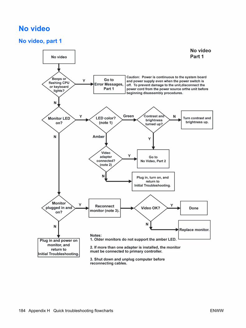
No videoNo video, part 1
184 Appendix H Quick troubleshooting flowcharts ENWW

No video, part 2
ENWW No video 185

No video, part 3
186 Appendix H Quick troubleshooting flowcharts ENWW

Error messagesError messages, part 1
ENWW Error messages 187

Error messages, part 2
188 Appendix H Quick troubleshooting flowcharts ENWW
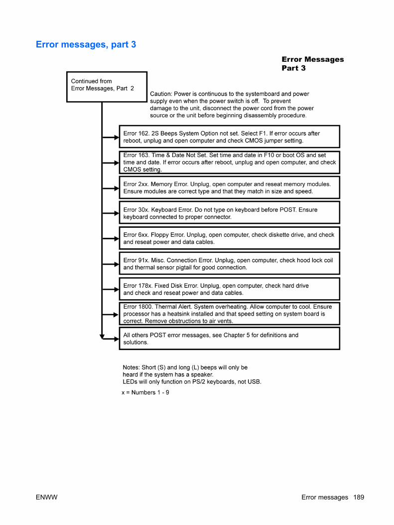
Error messages, part 3
ENWW Error messages 189

No operating system loading
190 Appendix H Quick troubleshooting flowcharts ENWW

No operating system loading from hard driveNo operating loading from hard drive, part 1
ENWW No operating system loading from hard drive 191

No operating system loading from hard drive, part 2
192 Appendix H Quick troubleshooting flowcharts ENWW

No operating system loading from hard drive, part 3
ENWW No operating system loading from hard drive 193

No operating system loading from diskette drive
194 Appendix H Quick troubleshooting flowcharts ENWW

No operating system loading from optical drive
ENWW No operating system loading from optical drive 195

No operating system loading from network
196 Appendix H Quick troubleshooting flowcharts ENWW

Non-functioning device
ENWW Non-functioning device 197

198 Appendix H Quick troubleshooting flowcharts ENWW

I PCI bus layout
ENWW 199

PCI bus layout and device listThe following illustration shows the HP xw9400 Workstation PCI bus layout. It is followed by a PCI devicelist description.
Figure I-1 PCI bus layout
Table I-1 PCI device list
Device Bus# Dev# Fn#
MCP55ProPro HT Config 0 0 0
MCP55ProPro LPC 0 1 0
200 Appendix I PCI bus layout ENWW

Device Bus# Dev# Fn#
MCP55Pro SMBUS 0 1 1
MCP55Pro Trim 0 1 2
MCP55Pro ASF SMU 0 1 3
MCP55Pro USB OHCI 0 2 0
MCP55Pro USB EHCI 0 2 1
MCP55Pro IDE 0 4 0
MCP55Pro SATA0 0 5 0
MCP55Pro SATA1 0 5 1
MCP55Pro SATA2 0 5 2
MCP55Pro P2P Bridge (Bridge to Slot 3) 0 6 0
MCP55Pro High Definition Audio Controller 0 6 1
MCP55Pro LOM 0 0 8 0
MCP55Pro LOM 1 0 9 0
MCP55Pro PCIE Root Port 0 (Port to Slot 2) 0 F 0
MCP55Pro PCIE Root Port 2 (Port to NEC Bridge) 0 D 0
MCP55Pro PCIE Root Port 5 (Port to Slot 1) 0 A 0
IO55 HT Config 40h 0 0
IOP55 LPC 40h 1 0
IOP55 SMBUS 40h 1 1
IOP55 Trim 40h 1 2
IO55 PCIE Root Port 0 (Port to Slot 5) 40h F 0
IO55 PCIE Root Port 2 (Port to SAS) 40h D 0
IO55 PCIE Root Port 5( Port to Slot 4) 40h A 0
Slot 1 (PCIEx8) 5h 0 0
Slot 2 (PCIEx16) 18h 0 0
Slot 3 (32 bit PCI ) 1h 4 0
Slot 4 (PCIEx8) 45h 0 0
Slot 5 (PCIEx16) 58h 0 0
Slot 6 (PCIX 100) 2Ch 4 0
Slot 7 (PCIX 100/133) 2Ch 9 0
1394 Controller 1h 5 0
NEC PCIX Bridge Controller 2Bh 0 0
NEC PCIX Bridge Controller (No Physical Slot Connections) 2Bh 0 1
LSI SAS Controller 6Bh 0 0
Table I-1 PCI device list (continued)
ENWW PCI bus layout and device list 201

202 Appendix I PCI bus layout ENWW