hp references in this manual - dudley labdudleylab.com/hp 8514b test set 45mhz to 20ghz manual.pdfhp...
TRANSCRIPT

Errata
Title & Document Type: 8514B S-Parameter and 8512A Reflection TransmissionTest Sets Manual
Manual Part Number: 08514-90014
Revision Date: 1990-06-01
HP References in this Manual This manual may contain references to HP or Hewlett-Packard. Please note that Hewlett-Packard's former test and measurement, semiconductor products and chemical analysis businesses are now part of Agilent Technologies. We have made no changes to this manual copy. The HP XXXX referred to in this document is now the Agilent XXXX. For example, model number HP8648A is now model number Agilent 8648A.
About this Manual We’ve added this manual to the Agilent website in an effort to help you support your product. This manual provides the best information we could find. It may be incomplete or contain dated information, and the scan quality may not be ideal. If we find a better copy in the future, we will add it to the Agilent website.
Support for Your Product Agilent no longer sells or supports this product. You will find any other available product information on the Agilent Test & Measurement website:
www.tm.agilent.com Search for the model number of this product, and the resulting product page will guide you to any available information. Our service centers may be able to perform calibration if no repair parts are needed, but no other support from Agilent is available.
HP 8514B S-PARAMETERand
HP 8512A REFLECTION/TRANSMISSIONTEST SETSSERIAL NUMBERS
This manual applies directly to HP 8514B test sets with serialprefix 2706A and to HP 8512A test sets with serial prefix2631A.
For additional information about serial numbers, refer toINSTRUMENTS COVERED BY MANUAL in the GeneralInformation section.
0 Copyright HEWLETT-PACKARD COMPANY 19871400 FOUNTAINGROVE PARKWAY, SANTA ROSA, CA 95403 U.S.A.
MANUAL PART NO. 08514-90014
Microfiche Part Number 08514-90015Printed: JUNE 1990
HEWLETTPACKARD

CERTIFICATION
Hewlett-Packard Company certifies that this product met its published specifications at the time of shipment from thefactory. Hewlett-Packard further certifies that its calibration measurements are traceable to the United States NationalInstitute of Standards and Technology (N/ST, formerly NBS), to the extent allowed by the Institute’s calibration facility, andto the calibration facilities of other International Standards Organization members.
WARRANTY
This Hewlett-Packard system product is warranted against defects in materials and workmanship for aperiod corresponding to the individual warranty periods of its component products. Computer and computerperipherals are warranted for a period of 90 days. Instruments are warranted for a period of one year. Duringthe warranty period, Hewlett-Packard Company will, at its option, either repair or replace products whichprove to be defective.
Warranty service for products installed by HP and certain other products designated by HP will be performedat Buyer’s facility at no charge within HP service travel areas. Outside HP service travel areas, warrantyservice will be performed at Buyer’s facility only upon HP’s prior agreement and Buyer shall pay HP’s roundtrip travel expenses. In all other areas, products must be returned to a service facility designated by HP.
For products returned to HP for warranty service, Buyer shall prepay shipping charges to HP and HP shallpay shipping charges to return the product to Buyer. However, Buyer shall pay all shipping charges, duties,and taxes for products returned to HP from another country.
HP warrants that its software and firmware designated by HP for use with an instrument will execute itsprogramming instructions when properly installed on that instrument. HP does not warrant that the opera-tion of the instrument, or software, or firmware will be uninterrupted or error free.
LIMITATION OF WARRANTY
The foregoing warranty shall not apply to defects resulting from improper or inadequate maintenance byBuyer, Buyer-supplied software or interfacing, unauthorized modification or misuse, operation outside ofthe environmental specifications for the product, or improper site preparation or maintenance.
NO OTHER WARRANTY IS EXPRESSED OR IMPLIED. HP SPECIFICALLY DISCLAIMS THE IMPLIEDWARRANTIES OR MERCHANTABILITY AND FITNESS FOR A PARTICULAR PURPOSE.
EXCLUSIVE REMEDIES
THE REMEDIES PROVIDED HEREIN ARE BUYER’S SOLE AND EXCLUSIVE REMEDIES. HP SHALL NOTBE LIABLE FOR ANY DIRECT, INDIRECT, SPECIAL, INCIDENTAL, OR CONSEQUENTIAL DAMAGES,WHETHER BASED ON CONTRACT, TORT, OR ANY OTHER LEGAL THEORY.
ASSISTANCE
Product maintenance agreements and other customer assistance agreements are available for Hewlett-Packard products.
For any assistance, contact your nearest Hewlett-Packard Sales and Service Office. Addresses are provided at the back ofthis manual.
8P24.2

DECLARATION OF CONFORMITYaccording to ISO/IEC Guide 22 and EN 45014
Manufacturer’s Name: Hewlett-Packard Co.
Manufacturer’s Address: 1400 Fountaingrove ParkwaySanta Rosa, California 95403U.S.A.
Declares that the product:
Product Name: S-Parameter Test Set
Model Numbers: HP 8514B
Product Options: This declaration covers all optionsof the above product(s).
Conforms to the following product specifications:
Safety:
EMC:
IEC 348:1978/HD 401:1980CAN/CSA-22.2 No. 231 Series M89CISPR 11:1990 /EN 55011:1991, Group 1 Class AIEC 801-2:1991 /EN 50082-1:1992,4 kV CD, 8 kV ADIEC 801-3:1984 /EN 50082-1:1992,3 V/m, 27-500 MHzIEC 801-4:1988 /EN 50082-1:1992, 500 V signal, 1000 V AC
Supplementary Information:
The product herewith complies with the requirements of the Low Voltage Directive 73/23/EEC andthe EMC Directive 89/336/EEC.
The HP 8514B was qualified as part of a product family which includes the HP 851OC, HP 8530A,HP 8511A, HP 8511B, HP
Santa Rosa, California
Location
European Contact:Your local Hewlett-Packard Sales and Service Office or Hewlett-Packard GmbH, DepartmentZQ/Standards Europe, Herrenberger Stra8e 130, D-7030 Biiblingen (FAX: $49-7031-143143)
Notice for Germany: Noise Declaration LpA < 70 dBam Arbeitsplatz (operator position)normaler Betrieb (normal position)nach DIN 45635 T. 19 (per IS0 7779)
Regulatory Information
HP 85148/8512A Operating and Service Manual
TABLE OF CONTENTS
SECTION 1. GENERAL INFORMATION . . . . . . . . . . . 1-lIntroduction . . . . . . . . . . . . . . . . . . . . . . . . . . . . . . . l - lVerifying the Test Set . . . . . . . . . . . . . . . . . . . . . . . l - lInstruments Covered by Manual . . . . . . . . . . . . . . l-2Description and Operating Characteristics
of the Instrument . . . . . . . . . . . . . . . . . . . . . . . l-2Options . . . . . . . . . . . . . . . . . . . . . . . . . . . . . . . . . . l-4
Option 001 . . . . . . . . . . . . . . . . . . . . . . . . . . . . . 1-4Option 002 (HP 8514B only) . . . . . . . . . . . . . . . . l-4Option 003 (HP 8514B only) . . . . . . . . . . . . . . . . l-4Option 002/003 (HP 85148 only) . . . . . . . . . . . . l-4Option908 . . . . . . . . . . . . . . . . . . . . . . . . . . . . . l-4Option 910 . . . . . . . . . . . . . . . . . . . . . . . . . . . . . l-4Option913 . . . . . . . . . . . . . . . . . . . . . . . . . . . . . l-4Option W03, Warranty Conversion . . . . . . . . . . l-4Option W30, Extended Service . . . . . . . . . . . . . l-4
Accessories . . . . . . . . . . . . . . . . . . . . . . . . . . . . . . . 1-5Accessories Supplied . . . . . . . . . . . . . . . . . . . . l-5Accessories Available . . . . . . . . . . . . . . . . . . . . l-5
Operating and Safety Precautions . . . . . . . . . . . . . l-6Operating . . . . . . . . . . . . . . . . . . . . . . . . . . . . . . l-6Service . . . . . . . . . . . . . . . . . . . . . . . . . . . . . . . . l-6
Additional Equipment Required . . . . . . . . . . . . . . . l-6
SECTION 2. INSTALLATION . . . .Introduction . . . . . . . . . . . .Initial Inspection . . . . . . . . . . .Environmental Considerations
Operation and Storage . . .Preparation for Use . . . . . . . .
Positioning the Test Set . . .Connecting the Test Set . .
Packaging . . . . . . . . . . . . . . . .
SECTION 3. OPERATION . . . . . .Introduction . . . . . . . . . . . . . . . .Front Panel Features . . . . . . . .Rear Panel Features . . . . . . . . .Operator’s Check . . . . . . . . . . .
Equipment . . . . . . . . . . . . . .Procedure . . . . . . . . . . . . . . . . .HP 85148 Operator’s Check . .
Sampler Test . . . . . . . . . . . .b1 Thru Test . . . . . . . . . . . . .b2 Thru Test . . . . . . . . . . . . .
.
. .
. .
. .
.......... 2-l. . . . . . . . . . 2-l. . . . . . . . . . 2-l. . . . . . . . . . 2-1. . . . . . . . . . 2-l. . . . . . . . . . 2-l. . . . . . . . . . 2-l. . . . . . . . . . 2-2. . . . . . . . . . 2-5
.............. 3-l. . . . . . . . . . . . . . 3-l. . . . . . . . . . . . . . 3-2. . . . . . . . . . . . . . 3-3. . . . . . . . . . . . . . 3-4. . . . . . . . . . . . . . 3-4. . . . . . . . . . . . . . 3-4. . . . . . . . . . . . . . 3-4. . . . . . . . . . . . . . 3-4. . . . . . . . . . . . . . 3-5. . . . . . . . . . . . . . 3-5
HP 8512A Operator’s Check . . . . . . . . . . . . . . . . . 3-6a1 Test . . . . . . . . . . . . . . . . . . . . . . . . . . . . . . . 3-6b1 Reflection Test . . . . . . . . . . . . . . . . . . . . . . . 3-6b2 Thru Test . . . . . . . . . . . . . . . . . . . . . . . . . . . 3-6
Controlling Multiple Test Sets . . . . . . . . . . . . . . . . 3-7Installation . . . . . . . . . . . . . . . . . . . . . . . . . . . . . . . 3-7Operation . . . . . . . . . . . . . . . . . . . . . . . . . . . . . . . . 3-7
Initialization at Power-up . . . . . . . . . . . . . . . . . 3-7Selecting a Test Set . . . . . . . . . . . . . . . . . . . . . 3-9Measurement Calibration . . . . . . . . . . . . . . . . . 3-9Operational Checks . . . . . . . . . . . . . . . . . . . . . 3-9Performance Verification . . . . . . . . . . . . . . . . . 3-9
Cable and Anti-Rotation Clamp Installation . . . . . 3-11Procedure . . . . . . . . . . . . . . . . . . . . . . . . . . . . . . . 3-11
SECTION 4. SPECIFICATIONS . . . . . . . . . . . . . . . . 4-1Mechanical Specifications . . . . . . . . . . . . . . . . . . 4-1Supplemental Characteristics . . . . . . . . . . . . . . . . 4-2
SECTION 5. TEST SET TROUBLESHOOTING . . . . . 5-lTest Set Temperature . . . . . . . . . . . . . . . . . . . . . . 5-2Check all Connections . . . . . . . . . . . . . . . . . . . . . 5-2Check Power Supply/Regulator, Fuses,
and Switches . . . . . . . . . . . . . . . . . . . . . . . . . 5-2A15 Regulator Board Assembly . . . . . . . . . . . . 5-2Fuses . . . . . . . . . . . . . . . . . . . . . . . . . . . . . . . . 5-2Address Switches . . . . . . . . . . . . . . . . . . . . . . . 5-3
Test Set Self-Test Indicators . . . . . . . . . . . . . . . . 5-3If Self-test Fails to Run . . . . . . . . . . . . . . . . . . . 5-3
Configuration Switch . . . . . . . . . . . . . . . . . . . . . . . 5-4Check VTO/Driver (LO) . . . . . . . . . . . . . . . . . . . . . 5-5Test Set Self-Test Indicators . . . . . . . . . . . . . . . . 5-5Test Set Troubleshooting Using Time Domain . . 5-6Test Set Assembly Replacement Procedures . . . 5-7(1) Bias Tee . . . . . . . . . . . . . . . . . . . . . . . . . . . . . . 5-9(2) Coupler . . . . . . . . . . . . . . . . . . . . . . . . . . . . . . . 5-l 0(3) Switch/Splitter . . . . . . . . . . . . . . . . . . . . . . . . . 510(4) Frequency Converter . . . . . . . . . . . . . . . . . . . . 5-10(5) Sampler . . . . . . . . . . . . . . . . . . . . . . . . . . . . . . 5-l 1(6) VT0 Assembly . . . . . . . . . . . . . . . . . . . . . . . . . 5-11(7) Regulator Board Assembly . . . . . . . . . . . . . . . 5-l 1(8) Step Attenuator Assembly . . . . . . . . . . . . . . . . 5-l 2(9) Capacitor . . . . . . . . . . . . . . . . . . . . . . . . . . . . . 5-l 2(10) 3.5 mm RF Connector Repair . . . . . . . . . . . . 5-12
Disassembly . . . . . . . . . . . . . . . . . . . . . . . . . . . 5-12
HP 8514B/85l2A Test Sets Table of Contents i
Assembly . . . . . . . . . . . . . . . . . . . . . . . . . . . . . 5-l 3(11) Fan . . . . . . . . . . . . . . . . . . . . . . . . . . . . . . . . . 5-13
Disassembly . . . . . . . . . . . . . . . . . . . . . . . . . . . 5-14Assembly . . . . . . . . . . . . . . . . . . . . . . . . . . . . . 5-l 4
(12) Port 1 3.5 mm ConnectorPort 2 3.5 mm Connector . . . . . . . . . . . . . . . 5-14
Center Pin Repair Procedure . . . . . . . . . . . . . . 5-l 53.5 mm Nut Repair Procedure . . . . . . . . . . . . . 5-15
(13) Power Transformer . . . . . . . . . . . . . . . . . . . . 5-15Unratioed Power Test . . . . . . . . . . . . . . . . . . . . . . 5-l 7HP 8512A Test Set . . . . . . . . . . . . . . . . . . . . . . . . 5-17
a1 Test . . . . . . . . . . . . . . . . . . . . . . . . . . . . . . . 5-18b1 Reflection Test . . . . . . . . . . . . . . . . . . . . . . . 5-l 8b2 Thru Test . . . . . . . . . . . . . . . . . . . . . . . . . . . 5-l 8
HP 85148 Test Set . . . . . . . . . . . . . . . . . . . . . . . . 5-18Sampler Test . . . . . . . . . . . . . . . . . . . . . . . . . . 5-l 8b1 Thru Test . . . . . . . . . . . . . . . . . . . . . . . . . . . 5-19b2 Thru Test . . . . . . . . . . . . . . . . . . . . . . . . . . . 5-l 9Next Step . . . . . . . . . . . . . . . . . . . . . . . . . . . . . 5-19
If Any User Channel Looks Bad . . . . . . . . . . . . . . 5-29Equipment . . . . . . . . . . . . . . . . . . . . . . . . . . . . . 5-29Service Procedure . . . . . . . . . . . . . . . . . . . . . . 5-30Service Adapter Conclusions . . . . . . . . . . . . . . 5-30
SECTION 6. REPLACEABLE PART6 . . . . . . . . . . . . 6-lIntroduction . . . . . . . . . . . . . . . . . . . . . . . . . . . . . . 6-lExchange Assemblies Available . . . . . . . . . . . . . . 6-lReplaceable Parts Lists . . . . . . . . . . . . . . . . . . . . . 6-2
Manufacturer Codes andReference Designations . . . . . . . . . . . . . . . . . 6-2
HP 8514B Replaceable Parts . . . . . . . . . . . . . . 6-3HP 8514B Top View Showing Locations of
Major Assemblies . . . . . . . . . . . . . . . . . . . . . . 6-7HP 8514B Miscellaneous Mecnahical, Chassis,
and Electrical Parts . . . . . . . . . . . . . . . . . . . . . 6-8HP 8514B and HP 8512A Motherboard
Component Location Diagram . . . . . . . . . . . . 6-13Parts Unique to HP 85148 and
8512A Option 001 (1 of 2) . . . . . . . . . . . . . . . . 6-14Parts Unique to HP 85148 Option 002 . . . . . . . 6-16HP 85148 Ports 1 and 2 Replaceable Parts . . 6-17Parts Unique to HP 85148 Option 003 . . . . . . . 6-l 8HP 8514B Option 002/003 Parts . . . . . . . . . . . 6-20HP 8512A Replaceable Parts . . . . . . . . . . . . . . 6-22HP 8512A Top view Showing Locations of
Major Assemblies . . . . . . . . . . . . . . . . . . . . . . 6-26HP 8512A Miscellaneous Mechanical, Chassis
and Electrical Parts . . . . . . . . . . . . . . . . . . . . . 6-27HP 8512A Port 1 and Port 2
Replaceable Parts . . . . . . . . . . . . . . . . . . . . . 6-32
SECTION 7. SERVICE . . . . . . . . . . . . . . . . . . . . . . . . 7-l
SECTION 6. PERFORMANCE TESTS . . . . . . . . . . . . 8-l
SECTION 9. ADJUSTMENTS . . . . . . . . . . . . . . . . . . 9-l
SECTION 10. MANUAL BACKDATING . . . . . . . . . . . 1 o-1
ii Table of Contents HP 8514B/8512A Test Sets
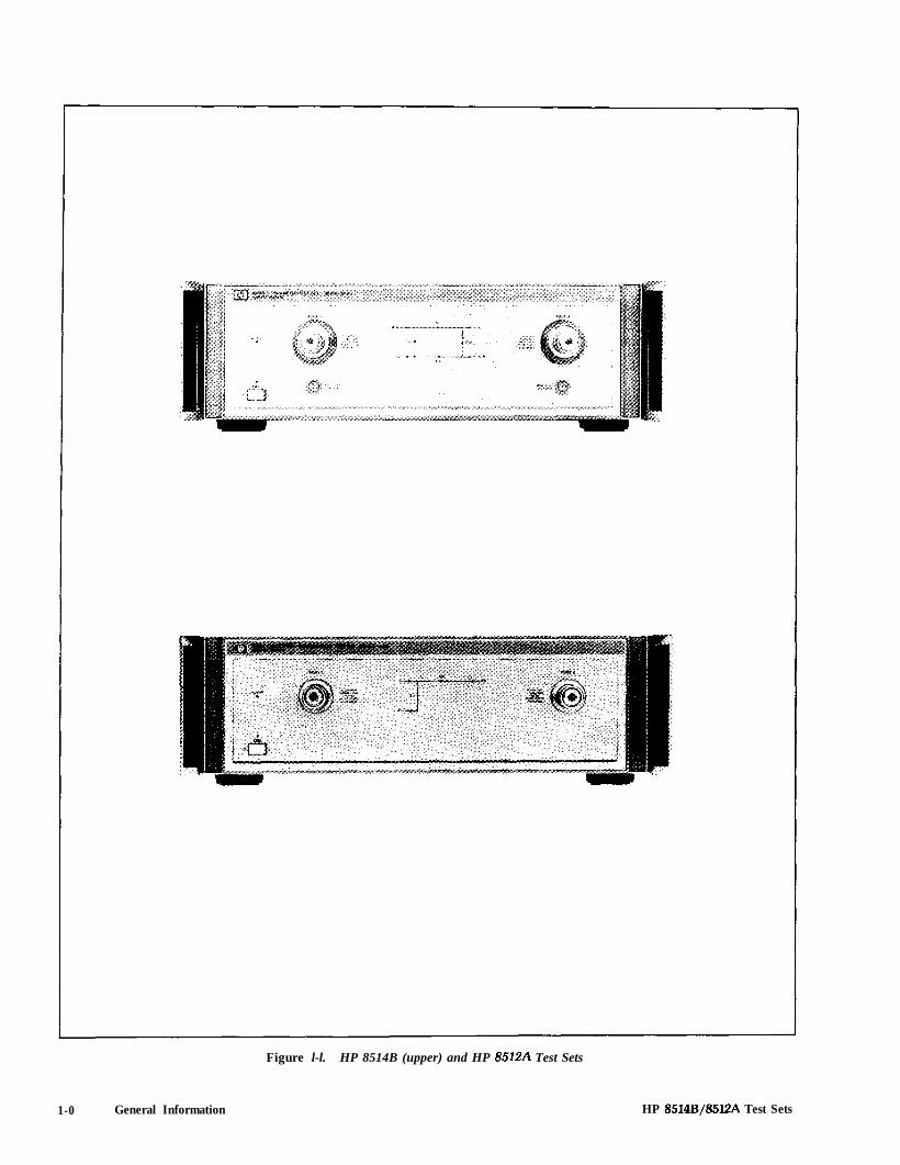
Figure l-l. HP 8514B (upper) and HP 8512A Test Sets
1-0 General Information HP 8514B/85lZA Test Sets

Section 1. General Information
The purpose of this manual is to enable you to use your HP 8514B S-parameter or HP 8512A reflection/transmission test set effectively and confidently. These test sets are integral components of theHP8510 measurement system. For that reason, this manual has been divided into two major portions(Operating and Service) to be an integral part of the HP8510 documentation.
l General Information0 Installation0 Operationl Performance Testsl Adjustmentsl Backdating
The Service part consists of :
l Replaceable Parts0 Service
The major topics of this section, General information, are:
l how to use the test setl what the test set isl operating, safety and warranty considerations0 test set specifications
VERIFYING THE TEST SET
The HP8514B and HP8512A have been designed to operate specifically with the HP8510 networkanalyzer.
0 To install the instrument, turn to the Installation section of this manual.
l To check the proper operation of the test set, see the Operator’s Check in the Operation section ofthis manual.
l To see the specifications of the test set refer to Specifications in the HP8570B System Manual orGenera/ information in volume 1 of the HP 8510A manual set.
HP 8514B/85l2A Test Sets General Information l - l

l To verify that the instrument meets its published specifications, turn to the Performance Testssection in the HP8510B System Manual or Volume 2 of the HP851OA Operating and Service Manual.Note that the HP8514B can be performance tested only to 18 GHz with the HP851OA software.
l To troubleshoot the test set, refer to the Service Overview section and the TestSet Troubleshootingsection of the HP8510B Service Manual. Or refer to the Service section in Volume 4 of the HP851OAOperating and Service Manual. Otherwise call your local Hewlett-Packard office.
INSTRUMENTS COVERED BY MANUAL
You will find a two-part serial number on the rear panel of the instrument. The first four digits and theletter are the serial number prefix. The last five digits are the sequential suffix which is unique to eachtest set. The contents of this manual apply directly to test sets with the same serial number prefix as theone(s) on the title page under the heading Serial Numbers.
If the serial prefix of your test set is not listed on the title page, your instrument differs from thosedocumented in this manual. The differences are documented in the yellow manual changes supplementsupplied with the manual.
To keep this manual as current and accurate as possible, Hewlett-Packard recommends that youperiodically request the latest manual changes supplement, as it may contain replacement informationas well as change information. The supplement for this manual is keyed to the manual’s print date andpart number (on the title page) and is available on request from Hewlett-Packard.
You can order this manual in microfiche form (the part number appears on the title page). With themanual (in 4 x 6 inch microfilm transparency format) you will also receive the latest manual changessupplement.
DESCRIPTION AND OPERATING CHARACTERISTICSOF THE INSTRUMENT
The combination of the HP 8514B test set with the HP8510 network analyzer and source provides asystem for making S-parameter measurements over the frequency range of 45 MHz to 20 GHz. Thissystem is suited for making measurements on two port devices when it is inconvenient or inexpedientto physically reverse the DUT (device under test) to measure all four S-parameters.
The HP8514B uses two couplers for signal separation. For measurements of active devices, thestandard HP 8514B includes:
l four RF to IF converters to measure all four S-parameters without reconnecting the DUT,l two 90 dB programmable step attenuators for changing (in 10 dB steps) the incident power
level at both ports,l two bias tees for applying external dc bias to both test port center conductors.
1-2 General Information HP 8514B/85l2A Test Sets

In the “High Forward Dynamic Range Configuration” (option 003) the Port 2 coupler is reversed tooptimize dynamic range in the forward measurement direction. Because the b2 sampler is connectedto the coupler through path instead of the coupled arm, there is less isolation between the b2 samplerand Port 2, and the b2 power level will be higher than bl. This configuration is better for wide dynamicrange or reciprocal devices or components like filters, cables, or antennas, where S,, is generally notmeasured. However, as a result of the lower isolation between the test port and the sampler, “samplerbounce,” appearing as an occasional spurious response related to the VT0 frequency, can benoticeable in this “asymmetrical” test set.
The HP 8512A reflection/transmission test set uses one coupler for signal separation. The standardHP 8512A has:
l three RF to IF converters, for making reflection (S,,) and transmission (S,,) measurements,l no step attenuators to internally change the incident power level,l no bias tees to apply external DC bias to the test port center conductors.
Tables 1 and 1B list additional characteristics of the HP85148 and 8512A, respectively. Figure l-2shows the HP 8514B in a typical measurement set-up.
8510 INTERCONNECT
~ 1 f J15 SOURCE CONTROL 1 ~, ! (
RF INPUT T E S T S E T
RF OUTPUT
TEST SET H P 8510BNETYORK ANALYZER
HP 83YO O R 83’41SYNTHESIZE0
WEEPER
Figure 1-2. Typical HP8514B Measurement Set-up
HP 8514B/8512A Test Sets General Information 1-3

Option 001This option adds IF switching capability to allow up to four test sets to be connected to the HP8510B atthe same time. The test set in use is selected from the HP85108 front panel. The 20 MHz IF signal istransmitted from the standard test set through the option 001 test set(s) to the network analyzer. IFswitching is performed automatically by the option 001 test set(s), without reconnections.
Option 002 (HP 85148 only)This option deletes the 90 dB programmable step attenuators and the dc bias tees. Note that bias canbe applied externally, using the HP11612A bias tee, if bias is required but attenuation not.
Option 003 (HP 85148 only)This high forward dynamic range configuration is described in detail in this section under the titleDescription and Operating Characteristics of the Instrument.
Option 002/003 (HP 85148 only)This option is a combination of option 002 and option 003, which were previously described.
Option 908This option supplies the test set with the parts required to rack mount it with handles removed. Refer tothe installation section of this manual for additional information.
Option 910This option provides a duplicate test set manual.
Option 913This option supplies the test set with the parts required to rack mount it with handles. Refer to theINSTALLATION section of this manual for additional information.
Option W03, Warranty ConversionOption W03 converts the standard one year return to Hewlett-Packard warranty to a 90 day on-sitewarranty. W03 can only be ordered at the time of instrument purchase. Instruments ordered with optionW03 are identified on the serial number label, or on a special identification label supplied with theinstrument.
Option W30, Extended ServiceOption W30 adds two additional years of return-to-HP service, to follow the first year of warranty.Option W30 can be ordered only at the time of purchase. Instruments ordered with option W30 areidentified on the serial number label, or on a special identification label supplied with the instrument.
NOTE: additional system warranty information is included in the HP8510 manual set.
1-4 General Information HP 8514B/85l2A Test Sets

ACCESSORIES
Accessories SuppliedFigure 3-1 shows the accessories supplied with the HP8514B and 8512A test sets (except as noted inTable 3-l). The accessories, with part numbers, are listed in the installation section for both test sets.
Accessories AvailableNOTE: Additional HP8510 system accessory information is located in the HP8510 manual set.
Calibration, Verification and Adapter Kits. Hewlett-Packard offers several calibration kits suitablefor calibrating an HP8510/8514B or 8512A when making error corrected measurements. Each calibra-tion kit noted below includes a set of precision standards to calibrate an HP8510 system in the indicatedinterface. Additional information is located in the System and Documentation Overview section of theHP8570B System Manual and volume 1 of the HP8510A manual set.
Connector Type
3.5 mm7mmType-N 5OQ3.5 to 7 mm
Calibration Kit Verification Kit
HP 850520/E HP 85053BHP 850508/C/D HP 85051 BHP 85054B HP 85055A
Adapter Kit
HP 85130A/B’
1. These adapters attach directly to the 3.5 mm test ports.
RF Cables. The HP 85131D 3.5 mm Test Port Return Cable Set is a pair of 21 inch long cables specifiedfrom DC to 26.5 GHz. Typically it is used with the HP8514B. One of the cables has 3.5 mm (f)connectors, the other cable has one 3.5 mm (f) and one 3.5 mm (m) connector.
The HP85132C 7 mm Test Port Return Cable is a single, 36 inch cable for measurements where thedevice is connected directly to one test port. It is typically used with the HP8512A. The cable has two7 mm connectors. Its frequency range is DC to 18 GHz.
Transistor Test Fixture Kit. The HP85041A Transistor Test Fixture Kit (TTF) is a comprehensivemeasurement system for testing and characterizing stripline packaged microwave transistors.Although it has 7 mm connectors and a frequency range limited to 18 GHz, the TTF may be easilyadapted for use with the HP 85148. Please consult with your local HP Systems Engineer for specificrecommendations.
HP 8514B/85l!2A Test Sets General Information l-5

Operating
AITENTIONStatic Sensitive
Handle only at Static SafeWork Stations
Beware of electro-static damage (ESD). The input connectors (test portsor cables or adapters connected to the test ports) are very sensitive toESD. Use a grounded wrist strap when attaching devices to the inputconnectors.
Otherwise, you need observe only normal precautions in handling and operating the test set. Do notexceed the front panel operating level power input as noted:
Maximum Operating Power Level Test Portf17 dBm HP8514B Port 1 and 2+20 dBm HP 8512A Port 1-13 dBm HP8512A Port 2
l Do not torque anything to the test port connector with greater than 90 N-cm (8in.-lb.) of torque. Thewrench supplied with your accessory kit is calibrated 90 N-cm (8 in.-lb.).
l Do not torque anything to the Source RF input, on the back of your test set, with greater than 90 N-cm (8 in.-lb.).
Service
The voltages in this test set warrant normal caution for operator safety. Nevertheless, service shouldbe performed only by qualified personnel. Service strategy, troubleshooting procedures, replaceableparts and similar information for the HP 85148 and 8512A test sets is in the HP85708 Service Manual.
Table 2-5 lists additional equipment and accessories required for use with the HP 8514B and 8512A testsets. The table notes which items are required to verify the performance of the test sets and which arerequired to operate them. Other equipment may be substituted if its specifications meet or exceed thespecifications listed in the critical specifications column.
l-6 General Information HP 8514B/8512A Test Sets

Section 2. Installation
INTRODUCTION
This section explains how to install the HP 8514B and HP8512A test sets. The topics covered includeinitial inspection, environmental considerations, positioning and connecting the test set for use, andpackaging the instrument. Refer to the Installation section of the HP8510 manual for more completesystem connection and turn-on instructions.
Inspect the shipping container (including cushioning material) for damage. If it is damaged, keep it untilyou have checked the contents for completeness. The contents are listed and illustrated in Figure 2-l.
In addition, check the test set mechanically and electrically. If the test set and shipping container areundamaged, passing the Operator’s Check (in the Operation section) should suffice for incominginspection. If the test set does not pass the Operator’s Check, refer to the troubleshooting proceduresin the service portion of this manual. Alternatively, call your local HP customer engineer.
If the shipping container is damaged, perform the performance tests outlined in the HP8510 manualset. If the test set fails the performance tests, or is damaged or defective, keep the shipping materialsand notify both the carrier and the nearest Hewlett-Packard office. The HP office will arrange for repairor replacement of the test set without waiting for settlement of the claim. If any of the followingaccessories are not received with the test set, notify your nearest HP office and the missing parts will besent to you.
Operation and StorageTo perform within specifications, the test sets should be operated in temperatures between 0°C and+55X with relative humidity less than 95% (at 40°C dry bulb temperature, maximum). They may beoperated at altitudes up to 4,500 metres (15,000 feet).
The test sets may be stored in temperatures from -40°C to +75”C, with relative humidity up to 90% at+65” (maximum dry bulb temperature) and at altitudes up to 15,240 metres (50,000 feet).
PREPARATION FOR USE
Positioning the Test SetTypically the test set is placed on a work surface whether it is rack-mounted or used on a bench. Toinstall the flanges to rack mount the instrument (with or without handles) in a standard 19 inch rack, referto Figure 2-2.
HP 8514B/85l2A Test Sets Installation 2-1
I
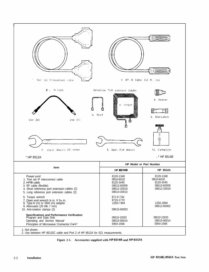
1. Test Set Interconnect Cable 2. HP-IB Cable 3.3 ft. long
3 . RF Cable Reference Port
SMA (M) SMA (F)9. Attenuator*
6 Torque Wrench 20 mm** 7. Open End Wrench 10. Clamp(s)**
* HP 8512A l * HP 8514B
HP Model or Part Numberitem
HP 05148 HP 8512A
Power cord’ 8120-1348 8120-13481. Test set IF interconnect cable 08510-60102 08510-601022. HPIB cable 8120-3445 8120-34453. RF cable (flexible) 08513-60009 08513-600094. Short reference port extension cables (2) 08512-20019 08512-200195. Long reference port extension cables (2) 08514-20013
6. Torque wrench 871 0-l 7647. Open end wrench l/z in. X 9/~6 in. 8710-17708. Type-N (m) to SMA (m) adapter 1250-l 894 1250-18949. Attenuator (20 dB, 7 mm) 08512-60002
10. Anti-rotation clamps (2) 08515-60003
Specifications and Performance VerificationProgram and Data Disk 08510-10033 08510-10033Operating and Service Manual’ 08515-90014 08515-90014Principles of Microwave Connector Care’ 5954-1566 5954-1566
1. Not shown.2. Use between HP 85132C cable and Port 2 of HP 8512A for S21 measurements.
Figure 2-1. Accessories supplied with HP8514B and HP851249
2-2 Installation HP 8514B/8512A Test Sets

OPTION 908RACK MOUNT KITWITH HANDLES REMOVEDHP Part Number 5061-9677
3. Remove feet before rack mounting.
1. Remove trim,screws. and handle.
2. Attach rack flange withpan head machine screws
FRONT OFINSTRUMENT
INSTRUMENT
OPTION 913RACK MOUNT KIT FOR
3. Remove feet before rack mounting.
INSTRUMENTS WITH PREVIOUSLYATTACHED FRONT HANDLESHP Part Number 5061-9771
( II
1. Remove trim and
2. Attach rack flange with2. Attach rack flange withpan head machine screws.pan head machine screws.
screws
\/’
I
_I’
,I’ 89”
_I’ et”
NT
INSTRUMENT
Figure 2-2. Attaching Rack Mounting Hardware
HP 8514B/8512A Test Sets Installation 2-3

The recommended rack is the HP85043A. Instructions for rack mounting the test set in a systemconfiguration with the HP8510 are provided in the HP8570 installation section and in the HP85043ASystem Rack Manual.
Static Free WorkstationWhen installing the test set for use on a bench, place it on a grounded anti-static work surface (Figure2-3) to lessen the chance of ESD damage. The anti-static surface should extend far enough in front ofthe test set to provide effective protection at the test ports and cable ends.
If your test set is equipped with a grounding receptical, you may use that in place of a static mat.
GROUNDINGRECEPTICAL
WRIST STRAP
A 3 WIRE LINE POWERCORD WITH PROPER
CONNECTION TO GROUND
MUST BE USED FOR ESD
PROTECTION.
Figure 2-3. Recommended Static Free Workstation
Connecting the Test SetMating Connectors. HP 8514B PORTS 1 and 2 are precision 3.5 mm male connectors and mate withprecision 3.5 mm female connectors. The HP 8512A has 7 mm test port connectors.
The TEST SET INTERCONNECT connector is a series D subminature female connector with 7 RFconnections.
The 8510 SYSTEM BUS connector is a female HPIB type connector and mates with the correspondingmale connectors of HPIB cables.
Power and Control Connections. Figure 2-4 shows the following connections (with the exception ofline power) and the required RF source connections.
Connect the power cord to an electrical outlet and the line module to supply power to the test set.
Connect the test set IF interconnect cable from the Jll TEST SET INTERCONNECT connector on therear panel of the test set to the Jl TEST SET INTERCONNECT connector on the rear panel of theHP85102 IF Detector.
2-4 Installation HP 8514B/85E!A Test Sets
Connect the system bus cable from the HP85148 (or 8512A) J12 8510 SYSTEM BUS connector to the8510 INTERCONNECTconnector of the HP85101 display/processor. The test set IF interconnect cableand the system bus cable transmit control signals between the test set and the network analyzer.
Signal Path Connections. The IF signals from the test set are transmitted to the HP 85102 IF Detectorby the test set IF interconnect cable (see above).
RF signals are transmitted from the source to the test set by the 3.5 mm flexible RF cable supplied withthe test set. Recommended torque is 56 N-cm (5in.-lb) for the RF cable-to-test-set/RF input connection.
Anti-Rotation Clamps. (HP8514B only) Use these clamps to stabilize the test port/RF cable connec-tion. Connect the test port cables to the test ports and tighten them as specified in the cable manual.Loosen the anti-rotation clamp thumb screw sufficiently to slip the clamp over the cable and up to thefront panel. The clamp end with the flats should come to rest on the flats of the test port shoulder. Fingertighten the thumb screws to prevent further loosening or tightening of the test port/RF cable connec-tion.
The internal O-ring is field replaceable without disassembling the anti-rotation clamp. Pry it out with finetweezers or a similar tool when it no longer holds the RF cable securely. Insert the new O-ring byengaging one side of it in the slot of the phenolic clamp donut. Use your fingers to push the O-ring intothe rest of the slot.
The HP part number of the O-ring is 0900-0007 (CD 7).
PACKAGING
If reshipping is required, each test set should be repackaged in the original factory package. Con-tainers and materials identical to those used by the factory are available through Hewlett-Packardoffices.
Alternatively, comparable packaging materials may be used. Wrap the test set in heavy paper or anti-static plastic. If shipping to an HP Office or Service Center, complete and attach a service tag (in theHP 8510 manual set). Use sufficient shock absorbing material on all sides of the test set to provide athick, firm cushion and prevent movement. Seal the shipping container securely and mark it FRAGILE.
In any correspondence with HP, refer to the test set by full model and serial number.
HP 8514Bf8512A Test Sets installation 2-5

8510SYSTEM
BUS
8510 INTERCONNECT -
RF INPUT
/’+
\ TEST SETINTER-
CONNECT.
HP 8519B/12ATEST SET
rc 8510 INTERCONNECT
FROMHP B5lOB
STOP SWEEPIN/OUT
HP-18
,’
.m\
I .o 0 0 0 0 0 000 DOOllO 0W r
HP 8390 OR BWlSYNTHESIZE0
WEEPER
FROMHP 85108
> lo “O’R *350BHP 8340/41USE ONE ONLY
Cr 8510 INTERCONNECT
HPINTERFACEBUS7
HP 83508SWEEP OSCILLATOR
Figure 2-4. HP 8514B and 8512A System Connections
2-6 Installation HP 8514B/8512A Test Sets
Section 3. Operation
This section illustrates the features and functions of the front and rear panels of the HP 8514B and8512A test sets. It also includes an operator’s check procedure. The function of the operator’s check isto confirm that the HP 8514B and HP 8512A test sets function properly as part of an HP 8510 system.The performance tests documented in the HP 85708 System Manual and volume 2 of the HP851OAmanual set are a more rigorous check. Volume 2 of the HP8510A manual set documents the HP8512Aonly.
l Also included in this section: a description of the Multiple Test Set Option (Option 001).
l Instructions for connecting a cable and anti-rotation clamp to your test set test port.
HP 8514B/SSl2A Test Sets Operation 3-l

1. Line Switch. This switch turns the test set on and off. Whenthe side of the switch labeled 0 is depressed, the test set isoff; I is on.
6. al LED. (HP8514B only) This LED indicates that theHP 85148 is internally switched to the Sl 1 or S21 mode andsource power is switched to Port 1.
2. Line LED. This LED goes on and off with the test set lineswitch.
7. a2 LED. (HP 85148 only) This LED indicates that theHP8514B is internally switched to the S22 or S12 mode andsource power is switches to Port 2.
3. Active LED. This LED lights about two seconds after poweris turned on, following the successful conclusion of self-test.
4. Port 1. This test port transmits RF energy from the sourceto the DUT and receives reflected RF energy from the DUT.The reflected RF energy is coupled to a sampler within theinstrument.
5. Bias Fuse. (HP8514B only) The fuse which limits biasapplied to Port 1 is within this holder (see the instrumentfront panel or the replaceable parts list for the value of thefuse Fl).
8. Bias Fuse. (HP8514B only) The fuse which limits biasapplied to Port 2 is within this holder (see the instrumentfront panel or the replaceable parts list for the value of thefuse F2).
9. Port 2. In the HP6514B, this test port transmits RF energyfrom the source to the DUT and receives reflected RF energyfrom the DUT.
In the HP8512A, this port only receives transmitted (fromPort 1) RF energy. The received RF energy is input directly toa sampler within the instrument.
Figure 3-1. Front Panel Features of HP 8514B (upper) and HP 8512A
3-2 Operation HP 8514B/8512A Test Sets

REAR PANEL FEATURES
10. Line module. This assembly houses the line cord connector, linefuse and line voltage selector. Pull out the right side of the linemodule cover to replace or change the fuse or to change the voltageselection. Note that the voltage selector drum must be removed torotate it to a different voltage setting. Recommended fuse values areprinted on the rear panel.
11. Extension A. This pair of 3.5 mm connectors holds the referenceport extension cable (RPEC. supplied) used to equalize the length ofthe reference signal-a2 sampler path with the test signal-b2 samplerpath.
When the DUT is connected to Port 2 with any of the recommendedRF cables, connect the long RPEC to Extension A.
12. Extension B. This pair of 3.5 mm connectors holds the referenceport extension cable (RPEC. supplied) used to equalize the length ofthe reference signal-al sampler path with the test signal-b1 samplerpath.
When the DUT is connected to Port 1 with any of the recommendedRF cables, connect the long RPEC to Extension 8. When the DUT isconnected directly to Port 1, connect the short RPEC to Extension B.
13. RF Input. This 35mm connector receives RF energy from thesource.
14. JlO Test Set Interconnect. This connector is used only in test setswith option 001. It allows connecting another test set to the option001 test set. Up to four test sets can be serially connected to theHP 8510. The HP 8510 system automatically selects the IF outputfrom the chosen test set for processing and display.
15. Jll Test Set Interconnect. This connector transmits the IF signalfrom the test set to the HP85102 IF Detector. It also transmits controlsignals bidirectionally.
18. 8510 System Bus Address Switch. This five-pole binary-weightedswitch sets the system bus address of the test set. The binary weightof each pole is indicated on the rear panel as are the on and offpositions. Decimal twenty (off-off-on-off-on. from left to right) is thedefault setting.
17. 512 8510 System Bus Connector. This connector is used for HPIBcommunications with the HP85101 display/processor.
18. Port 2 Bias. (HP8514B only) This female BNC connector is used tosupply bias through the center conductor of Port 2 to active devicesunder test.
19. Port 1 Bias. (HP8514B only) This female BNC connector is used tosupply bias through the center conductor of Port 1 to active devicesunder test.
HP 8514B/85lZA Test Sets
Figure 3-2. Rear Panel Features of HP 8514B (upper) and HP 8512A
Operation 3-3
Passing this check confirms that the HP 85146 and HP 8512A test sets function properly as part of anHP8510 system.
EquipmentItem HP Model or Part Number
Network analyzer system . . . . . . . . . . . . . . . . . . . . . . . . . . . . HP 8510A/BTest port return cable set . . . . . . . . . . . . . . . . . . . . . . . . . . . . HP85131DlTest port return cable . . . . . . . . . . . . . . . . . . . . . . . . . . . . . .85132-60005220 dB attenuator (pad) . . . . . . . . . . . . . . . . . . . . . . HP 8493C option 0202
1. use with HP851482. use with HP8512A
ProcedurePlug in and turn on the test set (it should not be connected to any other instrument or device now). Theline LED should light immediately and the active LED should light in about two seconds. Thoseindications mean that the instrument has passed its self-test. Turn off the test set and connect it to theHP8510 system as shown in Figure 3-3. Turn on all of the system instruments, network analyzer last.Let the instruments complete their self-tests.
Remove any cables or DUTs from the test set test ports. Press [PRESET] STIMULUS [MENU] on theHP85102 to preset the HP8510 and access the STIMULUS menu.
a. HP8340/41 systems: press [STEP] on the HP85101 to put the source in step mode.
b. HP8350B systems: press [SWEEP TIME] [2] [0] [0] [k/m] to set the sweep time to 200 ms. Innarrow band systems, the level of the frequency band generated should match the levels shown inFigure 3-3 for a given frequency.
Now perform either the HP8514B or 8512A Operator’s Check.
In case of difficulty, refer to Test Set Troubleshooting in the HP85708 Service Manual or contact yourlocal HP Service Office.
NOTE: All of the following HP8514B CRT traces should decrease from -20+5 dB at 2 GHz to-27 + 5 dB at 20 GHz.
Sampler Test1. To check all of the samplers in the HP 85148 test set, first redefine the a2 and b2 phase lock and
drive paths:
Press PARAMETER [MENU] [User 3 a21 [REDEFINE PARAMETER] [DRIVE] [Port 21 [PHASELOCK] [a21 [REDEFINE DONE] to redefine a2.
Press [User 2 b2] [REDEFINE PARAMETER] [DRIVE] [Port 21 [PHASE LOCK] [a21 [REDEFINEDONE] to redefine b2.
3-4 Operation HP 8514ES/8512A Test Sets
2. Connect an open (or short) to port 1 and port 2.
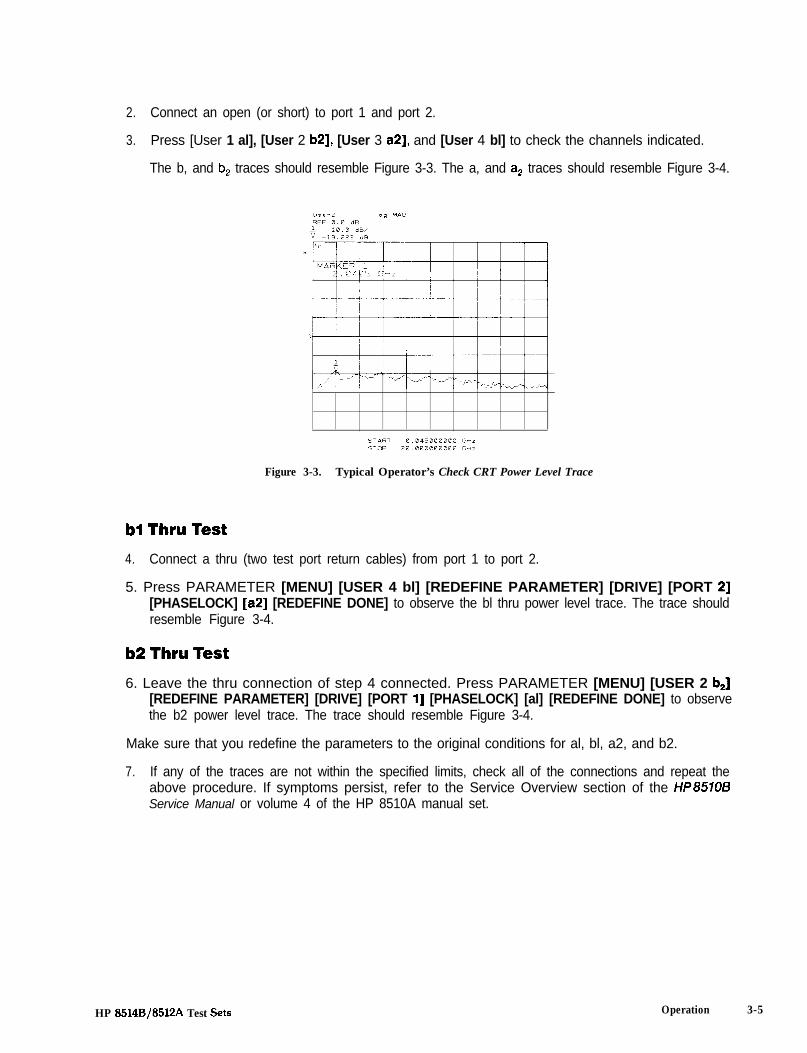
3. Press [User 1 al], [User 2 b2], [User 3 a2], and [User 4 bl] to check the channels indicated.
The b, and b, traces should resemble Figure 3-3. The a, and a2 traces should resemble Figure 3-4.
Figure 3-3. Typical Operator’s Check CRT Power Level Trace
bl Thru Test4. Connect a thru (two test port return cables) from port 1 to port 2.
5. Press PARAMETER [MENU] [USER 4 bl] [REDEFINE PARAMETER] [DRIVE] [PORT 21[PHASELOCK] [a21 [REDEFINE DONE] to observe the bl thru power level trace. The trace shouldresemble Figure 3-4.
b2 Thru Test6. Leave the thru connection of step 4 connected. Press PARAMETER [MENU] [USER 2 b2]
[REDEFINE PARAMETER] [DRIVE] [PORT l] [PHASELOCK] [al] [REDEFINE DONE] to observethe b2 power level trace. The trace should resemble Figure 3-4.
Make sure that you redefine the parameters to the original conditions for al, bl, a2, and b2.
7. If any of the traces are not within the specified limits, check all of the connections and repeat theabove procedure. If symptoms persist, refer to the Service Overview section of the HP857OBService Manual or volume 4 of the HP 8510A manual set.
HP 8514B/8512A Test Sets Operation 3-5

NOTE: All of the following HP8512A CRT traces should decrease from -2O+ 5 dB at 0.5 GHz to-32k5 dB at 18 GHz.
Figure 3-4. Typical Operator’s Check CRT Power Level Trace
al Test1. Press PARAMETER [MENU] [USER 1 al] to see the channel al power level trace.
bl Reflection Test2. Connect an open (or a short) to port 1.
3. Press [USER 4 bl] to observe the bl power level trace. The trace should resemble Figure 3-3.
b2 Thru Test4. Connect a thru (a 20 dB attenuator and test port return cable) between port 1 and port 2.
5. Press PARAMETER [MENU] [USER 2 b2] [REDEFINE PARAMETER] [DRIVE] [PORT l][PHASELOCK] [al] [REDEFINE DONE] to observe the b2 power level trace. The trace shouldresemble Figure 3-4.
6. If any of the traces are not within the specified limits, check all of the connections and repeat theabove procedure. If symptoms persist, refer to the Service Overview section of the W857OBService Manual or volume 4 of the HP 8510A manual set.
3-6 Operation HP 8514J3/8512A Test Sets
Controlling Multiple Test Sets
Option 001 for the HP 851X-series test sets allows an HP 8510 to alternately control up to four test sets.While a measurement is proceeding on Test Set number 1, which is equipped with option 001, testdevice hookup can be accomplished on Test Set number 2, which does not need to be equipped withoption 001, unless another test set is to be connected. When the measurement on test set number 1 iscomplete, then the HP 8510 can control test set number 2. Only one HP 8516A test set may be used in amultiple test set configuration.
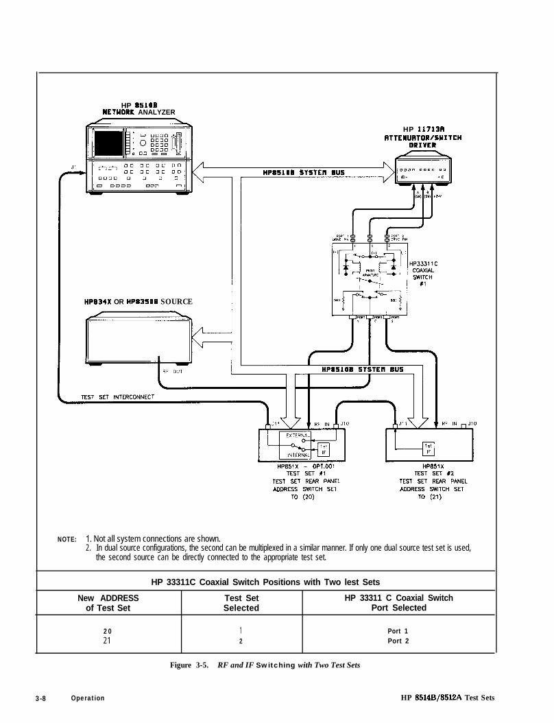
In a standard test set, the 20 MHz IF and control signals are applied directly to Jll TEST SETINTERCONNECT, which connects to the HP 8510. Option 001 adds a set of IF switches, controlswitches, and the JlO TEST SET INTERCONNECT connector. This allows the selection of 20 MHz testset IF signals. As shown in Figure 3-5, test set number 1 can apply its IF to the HP 8510 or it can switch topass the IF from test set number 2 through the JlO TEST SET INTERCONNECT to the HP 8510.
INSTALLATION
Set each test set rear panel address switch to the address listed in Figure 3-5, if using a two test setconfiguration and Figure 3-6, if configuring more than two test sets. Use the supplied Test SetInterconnect cable to connect test set number 1, Jll to the HP 8510. Use the supplied Test SetInterconnect cable to connect test set number 2, Jll to test set number 1, JlO. You may continue thistest set “daisy chain” to include up to four test sets if the total length of all Test Set Interconnect cablesdoes not exceed 13 meters (about 40 feet). The last test set in the chain does not require option 001.
If the RF coaxial switch(s) is not incorporated into the system, then the RF input to the test set must bemanually switched to the active test set.
OPERATION
Initialization at Power-upUpon power-up, the IF switches must be configured so that only one system test set is active. Thefollowing procedure shows how to make one test set active.
1. Check the active lights of all system test sets.
2. Check the HP 8510’s expected test set address by pressing [LOCAL] [TEST SET]. This shouldmatch the address of the desired test set. If not, change the address.
3. If unselected test sets are active, (active light ON), deactivate the test set by temporarily addressingit. Then return to the desired address.
HP 8514B/8512A Test Sets Operation 3-7
HP 85108NETYORK ANALYZER
HP 11713AATTENURTOR/SYITCH
DRIVER
HPB34X OR HPB35OB SOURCE
HP851X - OPT.001 HPBSlXTEST SET Xl TEST SET 12
TEST SET REAR PANEL TEST SET REAR PANEL
ADDRESS SWITCH SET ADDRESS SWITCH SET
TO (20) TO (21)
NOTE: 1. Not all system connections are shown.2. In dual source configurations, the second can be multiplexed in a similar manner. If only one dual source test set is used,
the second source can be directly connected to the appropriate test set.
HP 33311C Coaxial Switch Positions with Two lest Sets
New ADDRESS Test Set HP 33311 C Coaxial Switchof Test Set Selected Port Selected
20 1 Port 121 2 Port 2
Figure 3-5. RF and IF Switching with Two Test Sets
3-8 Operation HP 8514B/85l2A Test Sets
Selecting a Test SetTest Set IF Switching. The active test set is selected by the built-in capability of the HP 8510 togenerate an addressed command to the test set. Each time the HP 8510 ADDRESS of TEST SETfunction is changed (see HP 8510 LOCAL Menu), the HP 8510 switches the previously addressed testset IF to external and the newly addressed test set IF to internal. The test set front panel ACTIVEindicator shows the test set status. When the test set is active the IF signals from the test set are applieddirectly to Jll TEST SET INTERCONNECT. When the test set is inactive the IF signals appearing at JlOare passed through to Jll and on to the next test set or the HP 8510.
The address of the test set can be changed manually from the HP 8510 front panel by selecting theADDRESS of TEST SET function then entering the address of the test set and pressing [xl], or it can bechanged under program control using the HP 8510 HP-IB ADDRTESS; command. The HP-IB addressof a particular test set is set by address switches on the test set rear panel.
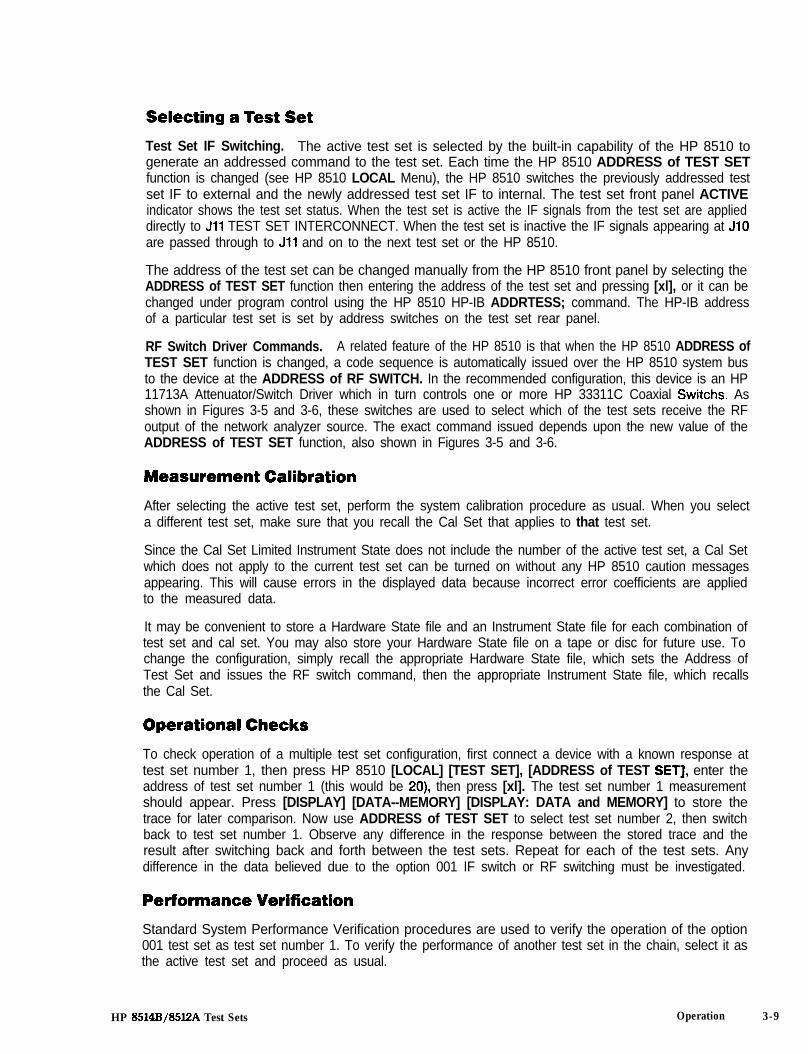
RF Switch Driver Commands. A related feature of the HP 8510 is that when the HP 8510 ADDRESS ofTEST SET function is changed, a code sequence is automatically issued over the HP 8510 system busto the device at the ADDRESS of RF SWITCH. In the recommended configuration, this device is an HP11713A Attenuator/Switch Driver which in turn controls one or more HP 33311C Coaxial Switchs. Asshown in Figures 3-5 and 3-6, these switches are used to select which of the test sets receive the RFoutput of the network analyzer source. The exact command issued depends upon the new value of theADDRESS of TEST SET function, also shown in Figures 3-5 and 3-6.
After selecting the active test set, perform the system calibration procedure as usual. When you selecta different test set, make sure that you recall the Cal Set that applies to that test set.
Since the Cal Set Limited Instrument State does not include the number of the active test set, a Cal Setwhich does not apply to the current test set can be turned on without any HP 8510 caution messagesappearing. This will cause errors in the displayed data because incorrect error coefficients are appliedto the measured data.
It may be convenient to store a Hardware State file and an Instrument State file for each combination oftest set and cal set. You may also store your Hardware State file on a tape or disc for future use. Tochange the configuration, simply recall the appropriate Hardware State file, which sets the Address ofTest Set and issues the RF switch command, then the appropriate Instrument State file, which recallsthe Cal Set.
Operational ChecksTo check operation of a multiple test set configuration, first connect a device with a known response attest set number 1, then press HP 8510 [LOCAL] [TEST SET], [ADDRESS of TEST SETI, enter theaddress of test set number 1 (this would be 20) then press [xl]. The test set number 1 measurementshould appear. Press [DISPLAY] [DATA--MEMORY] [DISPLAY: DATA and MEMORY] to store thetrace for later comparison. Now use ADDRESS of TEST SET to select test set number 2, then switchback to test set number 1. Observe any difference in the response between the stored trace and theresult after switching back and forth between the test sets. Repeat for each of the test sets. Anydifference in the data believed due to the option 001 IF switch or RF switching must be investigated.
Performance VerificationStandard System Performance Verification procedures are used to verify the operation of the option001 test set as test set number 1. To verify the performance of another test set in the chain, select it asthe active test set and proceed as usual.
HP 8514B/85l2A Test Sets Operation 3-9

HP11713AA
s9 SO 1A +24\/ B A
HP3331 1CCOAXIALSWITCH
#2
7::‘ 5:‘ 21’
TO HP85108NETWORK ANALYZER
TEST SETINTERCONNECT
I
RF IN(FROM SOURCE)
:ic- cr- 12__ AL TEST SET P3 T E S T SET #iiJ
/
Ji’ RF !N JlO
HP851X - OPT.001 HP851X - OPT.001 HP851X - OPT.001 HP851 XTEST SET #l TEST SET #2 TEST SET #3 TEST SET #4
TEST SET REAR PANEL TEST SET REAR PANEL TEST SET REAR PANEL TEST SET REAR PANEL
ADDRESS SWITCH SET ADDRESS SWITCH SET ADDRESS SWITCH SET ADDRESS SWITCH SET
TO (21) TO (21) TO (22) TO (23)
NOTE: 1. Not all system connections are shown.2. In dual source configurations, the second can be multiplexed in a similar manner. If only one dual source test set is used,
the second source can be directly connected to the appropriate test set.
HP 33311C Coaxial Switch Positions with Four lest Sets
HP 33311 C Coaxial SwitchNew ADDRESS of lest Set Port Selected
Test Set SelectedSwitch #l Switch #2
20 1 Port 1 Port 121 2 Port 1 Port 222 3 Port 2 Port 123 4 Port 2 Port 2
Figure 3-6. RF and IF Switching with Four Test Sets
3-10 Operation HP 8514B/85lZA Test Sets

Cable and Anti-Rotation Clamp Installation
The HP 08515-60003 Anti-Rotation Clamps are used to secure the RF connections at the test ports ofseveral Hewlett-Packard test sets. When installed, each clamp holds the large nut that secures the testset RF port connector to the front panel, and the RF cable connector or the front panel adapter matedwith the port connector.
Without the clamps, the test port connections may become loose after moving the connected deviceand could invalidate calibrations and measurements.
NOTE: Although the anti-rotation clamps may be used with front panel adapters, these instructionsrefer to an installation using the HP RF Cables. Adapter installations will be similar.
1. Two anti-rotation clamps are included in the test set accessories box. Remove one from the boxand loosen the thumbscrew until it is almost out of the counter-bored hole in the clamp body.
Gently push the clamp (round-hole end first) over and past the RF cable connector you will connectto the test set RF port. The rubber O-ring in the round end of the clamp will fit tightly over theconnector. Wiggle the clamp if necessary to get it over the connector.
Connect the cable to the test port and tighten as specified in the cable manual. Make sure that youdo not twist the cable as you attach it to the test port. Use the torque wrench supplied with yourcalibration kit to tighten the cable to no more than 90 N-cm (8 in.-lb.).
2. Important! The test set RF connector is easily loosened so hold the RF cable throughout the rest ofthis procedure. Do not allow the cable to rotate.
3. See Figure 3-7. Turn the clamp so that the thumbscrew is pointing up. From there, turn the clamp tovisually align the clamp flats with the flats on the test port connector nut. This will minimize rotatingthe connector in the next step.
NOTE: The flats may be in any orientation in respect to the front panel.
MAKE SURE FLAT SURFACEON REAR OF CABLE CLAMP ISPARALLEL WITH FIAT SURFACE
OF TEST SET CONNECTOR
FRONT VIEW OFTEST SET CONNECTOR
FRONT VIEW OFCABLE CLAMP
Figure 3-7. Visually Aligning Clamp and Nut Flats
HP 8514B/85l2A Test Sets Operation 3-11
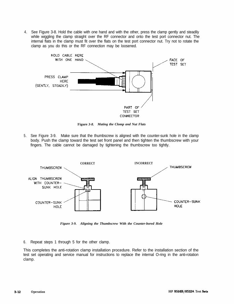
4. See Figure 3-8. Hold the cable with one hand and with the other, press the clamp gently and steadilywhile wiggling the clamp straight over the RF connector and onto the test port connector nut. Theinternal flats in the clamp must fit over the flats on the test port connector nut. Try not to rotate theclamp as you do this or the RF connection may be loosened.
HOLD CABLE HEREWITH ONE HAND FACE OF
TEST SET
PRESS CLAMPHERE
(GENTLY, STEADILY)
TEST SETCONNECTOR
Figure 3-8. Mating the Clomp and Nut Flats
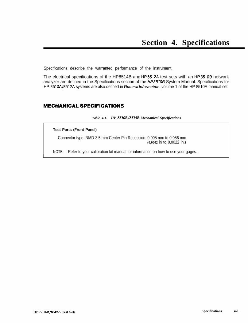
5. See Figure 3-9. Make sure that the thumbscrew is aligned with the counter-sunk hole in the clampbody. Push the clamp toward the test set front panel and then tighten the thumbscrew with yourfingers. The cable cannot be damaged by tightening the thumbscrew too tightly.
CORRECTTHUMBSCREW
ALIGN THUMBSCREWWITH COUNTER-
SUNK HOLE
COUNTER-SUNKHOLE
INCORRECTTHUMBSCREW
COUNTER-SUNKHOLE
Figure 3-9. Aligning the Thumbscrew With the Counter-bored Hole
6. Repeat steps 1 through 5 for the other clamp.
This completes the anti-rotation clamp installation procedure. Refer to the installation section of thetest set operating and service manual for instructions to replace the internal O-ring in the anti-rotationclamp.
3-12 Operation HP 8514B/85l2A Test !Sets
Section 4. Specifications
Specifications describe the warranted performance of the instrument.
The electrical specifications of the HP8514B and HP8512A test sets with an HP8510B networkanalyzer are defined in the Specifications section of the HP8570B System Manual. Specifications forHP 8510A/8512A systems are also defined in Generallnformation, volume 1 of the HP 8510A manual set.
MECHANICAL SPECIFICATIONS
Table 4-1. HP 8510B/8514B Mechanical Specifications
Test Ports (Front Panel)
Connector type: NMD-3.5 mm Center Pin Recession: 0.005 mm to 0.056 mm(0.0002 in to 0.0022 in.)
NOTE: Refer to your calibration kit manual for information on how to use your gages.
HP 8514B/85l2A Test Sets Specifications 4-l

SUPPLEMENTAL CHARACTERISTICS
The supplemental characteristics listed in the following tables are intended to provide informationusseful in applying the instrument by giving typical, but non-warranted, performance parameters.
Table 4-2. HP85108/8514B Characteristics
Test Ports (Front Panel)
Connector type: NMD-3.5 mm maleImpedance: 50 ohms nominalDC bias: 500 mA, 40 VDC, maximumIncident signal attenuation range: 0 to 90 dB in 10 dB stepsDamage input level: > +17 dBm CW RF’Nominal operating power level:’
Frequency Operating Level0.045 to 8 GHz +3 dBm8 to 20 GHz 0 dBm
Nominal connector nut size: 20 mmRecommended torque: 90 N-cm. (8 in.-lb.)
RF Input Connector (Rear Panel)
Connector type: precision 3.5 mm femaleDamage input level: > +23 dBmSource power levels for reference channel phase lock:
Minimum: 0 dBmMaximum: +14 dBm
Nominal connector nut size: 8 mmRecommended torque: 90 N-cm. ( 8 in.lb.) for precision 3.5mm
56 N-cm. (5 in.-lb.) for SMA
1, Do not exceed + 10 dBm input for proper operation.2. Available power in PRESET condition.
4-2 Specifications HP 8514B/85l2A Test Sets
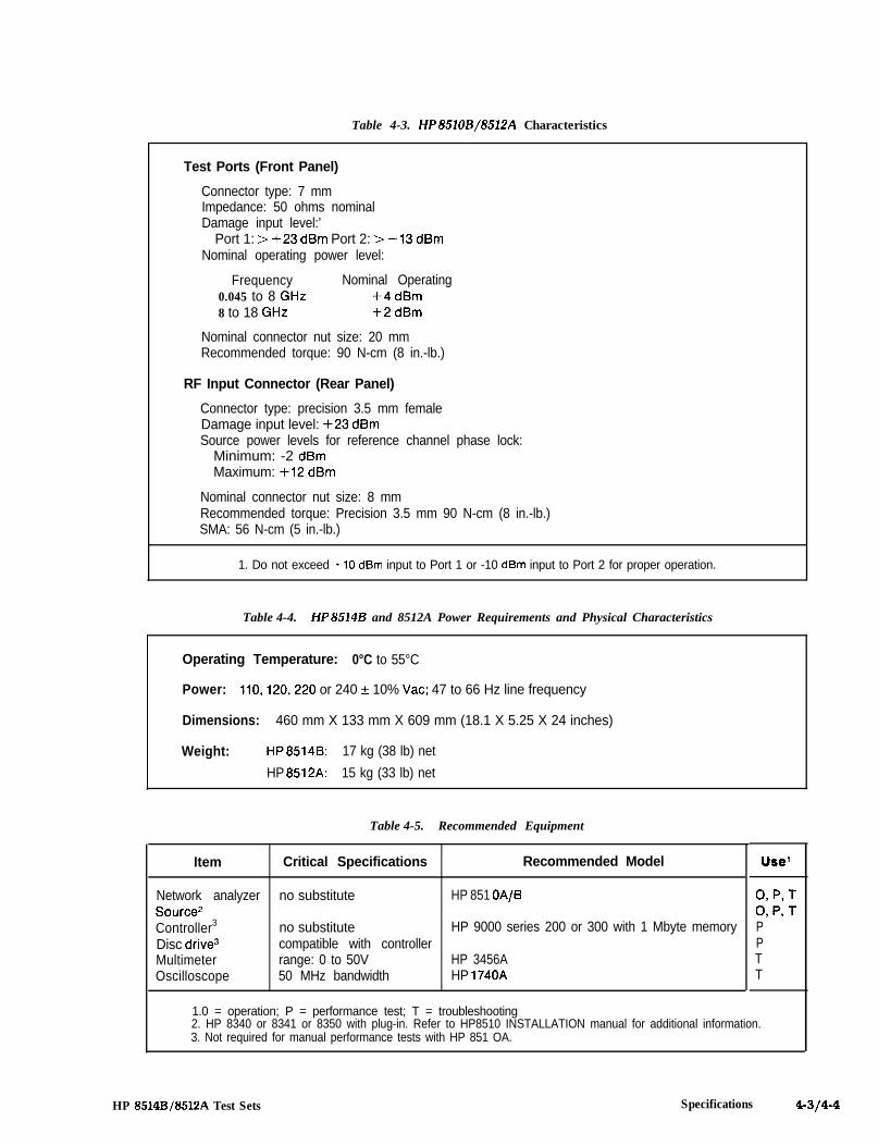
Table 4-3. HP851OB/8512A Characteristics
Test Ports (Front Panel)
Connector type: 7 mmImpedance: 50 ohms nominalDamage input level:’
Port 1: > +23 dBm Port 2: > +13 dBmNominal operating power level:
Frequency Nominal Operating0.045 to 8 GHz +4 dBm8 to 18 GHz +2 dBm
Nominal connector nut size: 20 mmRecommended torque: 90 N-cm (8 in.-lb.)
RF Input Connector (Rear Panel)
Connector type: precision 3.5 mm femaleDamage input level: +23 dBmSource power levels for reference channel phase lock:
Minimum: -2 dBmMaximum: +12 dBm
Nominal connector nut size: 8 mmRecommended torque: Precision 3.5 mm 90 N-cm (8 in.-lb.)SMA: 56 N-cm (5 in.-lb.)
1. Do not exceed +lO dBm input to Port 1 or -10 dBm input to Port 2 for proper operation.
Table 4-4. HP8514B and 8512A Power Requirements and Physical Characteristics
Operating Temperature: 0°C to 55°C
Power: 110,120,220 or 240 + 10% Vat; 47 to 66 Hz line frequency
Dimensions: 460 mm X 133 mm X 609 mm (18.1 X 5.25 X 24 inches)
Weight: HP8514B: 17 kg (38 lb) net
HP 8512A: 15 kg (33 lb) net
Table 4-5. Recommended Equipment
Item Critical Specifications Recommended Model
Network analyzer no substitute HP 851 OA/BSource2Controller3 no substitute HP 9000 series 200 or 300 with 1 Mbyte memoryDisc drive3 compatible with controllerMultimeter range: 0 to 50V HP 3456AOscilloscope 50 MHz bandwidth HP 1740A
1.0 = operation; P = performance test; T = troubleshooting2. HP 8340 or 8341 or 8350 with plug-in. Refer to HP8510 INSTALLATION manual for additional information.3. Not required for manual performance tests with HP 851 OA.
Use’
0, P, T0, P, TPPTT
HP 8514B/85l2A Test Sets Specifications 4-314-4
Section 5. Test Set Troubleshooting
The information consists of procedures for checking the following:
l Test Set Temperaturel Check All Connectionsl Check Power Supply/Regulator, Fuses, and Switchesl Test Set Self-test Indicatorsl Check VTO/Driver (LO)l Test Set Troubleshooting Using Time Domainl Test Set Assembly Replacement Proceduresl 3.5 mm RF Connector Repairl Unratioed Power Test
The information in this section is presented as an aid in troubleshooting the HP 8512A, HP 8514A, andHP 8514B test sets. If you are not certain that the problem with your system is due to a faulty test set,read the sections titled Service Overview and Built-/n Diagnostics in this manual. Continue with thissection only if you know the test set is faulty.
For specific information about the HP 8514A, refer to the material in the HP 8510A manual set.
HP 8514B/8512A Test Sets Test Set Troubleshooting 5-1

TEST SET TEMPERATURE
The processor on the A4 HP-IB assembly monitors the test set temperature with a comparator on theA3 VT0 summing amplifier. The temperature sensor is located on the Al4 VTO/driver assembly. If thetemperature of the VTO/driver exceeds 85°C the HP 85101 displays the “Test Set Too Hot” prompt.
TEST SET TOO HOT means turn off the test set immediately. This mes-sage is only a prompt. It does not turn off the test set.
Determine the reason for the prompt before again subjecting the test set to continuous use. Make surethe fan is operating properly and is not covered by a piece of paper, etc. Make sure the fan and the sidepanel air exhaust has at least 8 cm (about 3 inches) clearance, and top cover exhaust has at least 1.5 cm(about 0.5 inches) clearance.
CHECK ALL CONNECTIONS (loose, broken, crimped, etc.)
Power holes (power loss at a specific frequency) often result from faulty connections. Check thefollowing connections:
l Test set rear panel (including the extension links)l Cables connected to the A3 summing amplifier and A5 Attenuator/Switchl Sampler cablesl RF path connections from rear panel to front panel
CHECK POWER SUPPLY/REGULATOR, FUSES, AND SWITCHES
Al5 Regulator Board AssemblyUse a digital voltmeter to check the voltages given in Table 5-1. Use an oscilloscope to check AC ripple.Use chassis ground as reference.
Table 5-l. Test Set Power Supply Tolerances
Nominal Voltage Test Point
+15v Al 5TPl-15v Al 5TP2+5v Al 5TP3- 5 v Al 5TP6
Voltage Tolerance
+13.7 to +15.9v-13.8 to -16.2V+4.5 to +5.2V-4.8 to -5.5V
Maximum Ripple
2mV2mV2mV2mV
FusesFuses for the regulator board assembly, rear panel, and front panel are specified in the parts list of eachtest set. The locations of these fuses are also given in the parts list.
5-2 Test Set Troubleshooting HP 8514B/85l2A Test Sets
c
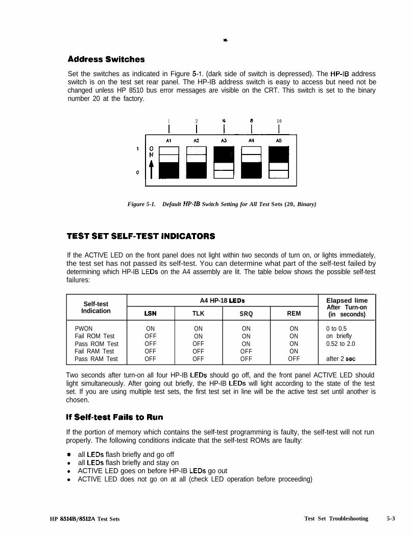
Address SwitchesSet the switches as indicated in Figure 5-l. (dark side of switch is depressed). The HP-18 addressswitch is on the test set rear panel. The HP-IB address switch is easy to access but need not bechanged unless HP 8510 bus error messages are visible on the CRT. This switch is set to the binarynumber 20 at the factory.
1 2 u 6 16
Figure 5-1. Default HP-B Switch Setting for All Test Sets (20, Binary)
TEST SET SELF-TEST INDICATORS
If the ACTIVE LED on the front panel does not light within two seconds of turn on, or lights immediately,the test set has not passed its self-test. You can determine what part of the self-test failed bydetermining which HP-IB LEDs on the A4 assembly are lit. The table below shows the possible self-testfailures:
Self-testIndication
PWONFail ROM TestPass ROM TestFail RAM TestPass RAM Test
LSN
ONOFFOFFOFFOFF
A4 HP-18 LEDs
TLK SRQ
ON ONON ONOFF ONOFF OFFOFF OFF
REM
ONONONONOFF
Elapsed limeAfter Turn-on(in seconds)
0 to 0.5on briefly0.52 to 2.0
after 2 set
Two seconds after turn-on all four HP-IB LEDs should go off, and the front panel ACTIVE LED shouldlight simultaneously. After going out briefly, the HP-IB LEDs will light according to the state of the testset. If you are using multiple test sets, the first test set in line will be the active test set until another ischosen.
If Self-test Fails to RunIf the portion of memory which contains the self-test programming is faulty, the self-test will not runproperly. The following conditions indicate that the self-test ROMs are faulty:
0 all LEDs flash briefly and go offl all LEDs flash briefly and stay onl ACTIVE LED goes on before HP-IB LEDs go outl ACTIVE LED does not go on at all (check LED operation before proceeding)
HP 8514B/8512A Test Sets Test Set Troubleshooting 5-3

I II I, , SUMMING AMP
-c
/
--r--y/
/ I \\
/ I \I I
I r - -I- - ? I/
’ //I I
I--+----.-+--,
I I L-I-A I I
L--lI
I L - - !I I\ I /\ /\ I /L----I-->
HP 8512A mi
HP 8514A/Bm
Figure 5-2. Location of A3 Assembly and A3 Configuration Switch Settings
The configuration switch is on the A3 summing amplifier assembly (see Figure 5-2). It is not easy toaccess or reset (you must remove the top cover, a bracket, and the A3 assembly). Therefore, unlessone of the following conditions exist, don’t change it. Reasons to suspect these switches are setincorrectly include:
l HP 8510 turn-on frequencies are not those of test set.
l HP 8510 allows selection of two port S-parameters with a transmission/reflection test set.
5-4 Test Set Troubleshooting HP 8514EI/85l2A Test sets

CHECK VTO/DRIVER (LO)
There are two procedures provided to check the VTO. The first one (a) checks the VT0 at twofrequencies, the second one (b) is more thorough and checks the VT0 at 12 frequencies throughout theVT0 range.
a. Using a frequency counter and a voltmeter, check the VT0 fundamental frequency and A3summing amplifier output as follows:
Disconnect the Test Set-IF Interconnect cable. Using a BNC-to-snap-on cable (provided in theservice kit) connect the frequency counter to A14Jl (labeled VT0 AUX, on the VT0 board assem-bly). Check that A14Jl is between 165 MHz and 195 MHz.
Disconnect the cable to A3J4. The VT0 frequency should be between 150 MHz and 190 MHz.Check that A3J4 is between -5.6 and -6.8 Vdc.
If the VT0 frequency is not correct, but the voltage at A3J4 is correct, suspect a bad VTO.
If the voltage at A3J4 is not correct, suspect a bad A3 summing amplifier assembly (assuming theHP 85102 is working).
b. Use a power supply and a frequency counter to check the VT0 as follows:
Inject a -1 to -12V DC voltage ( in -1 volt steps) into the Al4 VT0 drive (Al4J2). Monitor A14Jl toverify that the VT0 steps through its range of 65 MHz to 300 MHz (about -21.3 MHz/volt). Figure5-3 illustrates the relationship of voltage at A14J2 to VT0 oscillation frequency.
-12 -11 - 1 0 - 9 - 6 - 7 - 6 - 5 - 4 - 3 - 2 -1 0
NEGATIVE DC VOLTAGE AT AlW2
Figure 5-3. VT0 Voltage/Frequency Relationship
300MHz
250MEASURED
FREQUENCY200 AT Al’+ Jl
(VT0 AUX)
100
50
HP 8514Bj85EA Test Sets Test Set Troubleshooting 5-5

Time domain response of the test set can be used to identify problems in the RF path. The plots belowshow typical time domain responses of the HP 8512A, 8513A, 8514A/B, and 8515A test sets. These canbe used as rough standards when trying to locate a problem in the RF path. Keep in mind that theabsolute location in time and absolute height of the responses will vary from test set to test set. Thesignificant factor is the relative height of the main impulse (determined by the calibrated short) and thediscontinuities. Discontinuities that may be causing a problem will usually stand out as being muchgreater than the typical response.
Set up the system as follows to obtain a time domain trace:
1. Connect a short or shielded open to the test set port 1.
2. Press [PRESET] [DOMAIN] [TIME BAND PASS] STIMULUS [MENU] [NUMBER OF POINTS] [4][0] [l] [Sll] [LOG MAGI.
3. Set the START/STOP TIME, SCALE, and REF VALUE as indicated in Table 5-3, below.
Table 5-3. Suggested Parameter Values for Time Domain Troubleshooting
Test Set Start Time Stop Time Scale REF ValueRefer toFigure #
HP 8512A -1.0 ns 11.0 ns 10 dB/ - 2 0 dB 5-4HP 8514A/B -6 .0 ns 6.0 ns 5 dB/ - 2 0 dB 5-5
4. For the HP 8514A or 8515A, you can check the port 2 responses using the same set-up as describedabove except connect the termination to port 2 and select S22 instead of Sll. Peaks in the tracethat are significantly greater than those shown indicate a possible loose or bad connection in theRF path at that location.
Figure 5-4. HP 8512A Typical Port 1 Response
5-6 Test Set Troubleshooting HP 8514B/8512A Test Sets

Figure 5-5. HP 8514A/B Typical Port I and Port 2 Response
TEST SET ASSEMBLY REPLACEMENT PROCEDURES
This section describes how to replace HP 8510 test set major assemblies and components. The HP8510 test sets include the HP 8512A, 8514A, and 85148. This procedure does not explain how to remove7 mm connectors. If your test set has 7 mm connectors, refer to the test set manual for removalinstructions.
Not all of the procedures apply to all of the test sets. Nor do all of the test sets contain all of the partsdocumented in the following text and figures. Use them as applicable. The procedures appear in thisorder:
1 Bias tee2 Coupler3 Switch/splitter4 Frequency converter5 Sampler
6 VT0 assembly7 Regulator board assembly8 Step attenuator assembly9 Capacitor
10 3.5 mm RF connectors11 Fan12 Port 1 and 2 3.5 mm connectors13 Power transformer
Before beginning any of the following procedures:
l Turn the test set OFF.l Remove the top cover.l Reverse the following procedures to install parts.
HP 8514B/85l2A Test Sets Test Set Troubleshooting 5-7
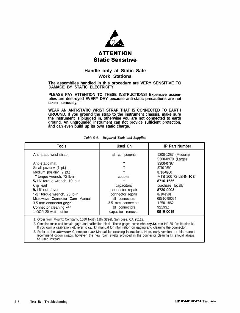
ATTENTIONStatic Sensitive
Handle only at Static SafeWork Stations
The assemblies handled in this procedure are VERY SENSITIVE TODAMAGE BY STATIC ELECTRICITY.
PLEASE PAY ATTENTION TO THESE INSTRUCTIONS! Expensive assem-blies are destroyed EVERY DAY because anti-static precautions are nottaken seriously.
WEAR AN ANTI-STATIC WRIST STRAP THAT IS CONNECTED TO EARTHGROUND. If you ground the strap to the instrument chassis, make surethe instrument is plugged in, otherwise you are not connected to earthground. An ungrounded instrument can not provide sufficient protection,and can even build up its own static charge.
Table 5-4. Required Tools and Supplies
Tools Used On HP Part Number
Anti-static wrist strap all components 9300-1257 (Medium)9300-0970 (Large)
Anti-static mat ‘I 9300-0797Small pozidriv (1 pt.) ‘I 8710-0899Medium pozidriv (2 pt.) ‘1 8710-09001” torque wrench, 72 lb-in coupler MTB 100 72 LB-IN 10E’5/l 6” torque wrench, 10 lb-in ‘I 8710-1655Clip lead capacitors purchase locally9/l 6” nut driver connector repair 8720-0008l/2” torque wrench, 25 lb-in connector repair 8710-1581Microwave Connector Care Manual all connectors 08510-900643.5 mm connector gage’ 3.5 mm connectors 1250-1862Connector cleaning kit3 all connectors 92193Z1 OOR 20 watt resistor capacitor removal 0819-0019
1. Order from Mountz Company, 1080 North 11th Street, San Jose, CA 95112.2. Contains male and female gage and calibration block. These gages come with any35 mm HP 8510calibration kit.
If you own a calibration kit, refer to cat kit manual for information on gaging and cleaning the connector.3. Refer to the Microwave Connector Care Manual for cleaning instructions. Note, early versions of this manual
recommend cotton swabs, however, the new foam swabs provided in the connector cleaning kit should alwaysbe used instead.
5-8 Test Set Troubleshooting HP 8514B/8512A Test Sets
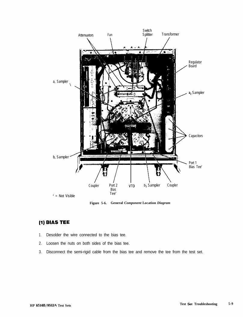
Attenuators FanSwitchSplitter Transformer
RegulatorBoard
a, Sampler\
a2 Sampler
Capacitors
b, Sampler ’
Port 1Bias Tee’
+ = Not Visible
Coupler Port 2BiasTee’
VT0 b, Sampler Coupler
Figure 5-6. General Component Location Diagram
(1) BIAS TEE
1. Desolder the wire connected to the bias tee.
2. Loosen the nuts on both sides of the bias tee.
3. Disconnect the semi-rigid cable from the bias tee and remove the tee from the test set.
HP 8514B/8512A Test Sets Test Set Troubleshooting 5-9

(2) COUPLER
1. Remove the bias tee as described in procedure (1).
2. Remove the aluminum shield (which covers the couplers), disconnect any wires that cross thecoupler and remove the two screws which attach the coupler to the test set chassis.
3. Disconnect the semi-rigid cable from the coupler to the sampler.
4. Carefully loosen the nut on the front of the test set with the 1 in. torque wrench. Remove the nut andwasher.
5. Move the coupler away from the front panel and lift it out of the test set.
6. Remove any brackets before sending the coupler to HP for repair.
(3) SWITCH/SPLITTER
NOTE: Reflection/transmission test sets use a splitter rather than a combination switch/splitter. Bothdevices are installed in the same place in the various test sets.
1. Remove the semi-rigid cables from the switch/splitter with the 5/16 in. wrench. (Reposition anyother cables as required to ease removal.)
2. Remove the four (4) screws which attach the switch/splitter mounting bracket to the chassis.
3. Remove the switch/splitter and bracket from the test set.
4. Remove the bracket from the switch/splitter before sending the switch/splitter to HP for repair.
(4) FREQUENCY CONVERTER
The frequency converter consists of a VT0 (voltage-tuned oscillator) assembly and three or foursamplers.
ATTENTIONStatic Sensitive
Handle only at Static SafeWork Stations
The frequency converter is especially sensitive to electrostatic dis-charge. Wear a ground strap that is connected to earth ground whenperforming this procedure.
5-10 Test Set Troubleshooting HP 8514B/85l2A Test Sets

1. Remove the semi-rigid cables from the samplers.
2. Remove the in-line attenuators from the samplers.
3. Remove all flexible cables from the frequency converter by gently pulling on the gold connector.
4. Unplug the ribbon cable near the front panel.
5. Unplug the harnessed (multi-colored) wire and socket assemblies.
6. Remove the four (4) frequency converter mounting plate screws and the frequency converterbracket screw that fastens the frequency converter to the chassis. Lift the frequency converter outof the test set.
7. Remove the frequency converter bracket by removing the two (2) pozidriv screws before sendingthe frequency converter in for repair.
NOTE: Torque all SMA connections to 56 N-cm (5 in.-lb) with the 5/16” torque wrench.
(5) SAMPLER
1. Remove the frequency converter (4) from the test set.
2. Remove the heat sink from the VT0 by removing the eight (8) screws that hold it to the VTO.
3. Remove the two (2) sampler mounting screws from the opposite ends of the sampler. Loosen thenut connecting the VT0 to the sampler and remove the sampler.
(6) VT0 ASSEMBLY
1. Remove the frequency converter (4) from the test set.
2. Remove the 2 sampler mounting screws from each sampler. (The VT0 heat sink may need to beremoved for access.)
3. Loosen the nuts connecting the VT0 to each sampler, disconnect the samplers and remove theVT0 assembly.
4. Remove the two (2) VT0 mounting bracket screws to separate the bracket from the VT0 beforereturning the VT0 to HP for repair.
(7) REGULATOR BOARD ASSEMBLY
1. Unplug the transformer socket from the regulator board.
2. Remove the three (3) mounting screws from the top edge of the regulator board. (It may benecessary to disconnect some semi-rigid cables to ease removal of the screws.)
3. Remove the regulator board. (It may be necessary to partially back out one of the transformermounting screws for clearance.)
HP 85148/8512A Test Sets Test Set Troubleshooting 5-11

1. Unplug the ribbon cables of the step attenuator to be removed. (Remove the regulator board (7) toaccess the ribbon cable sockets if necessary.)
2. Remove the attenuator mounting bracket screws.
3. Remove the attenuator and mounting bracket from the test set.
4. Remove the mounting bracket from the attenuator before sending the attenuator to HP for repair.
(9) CAPACITOR
1. Set the test set upright and pull the metal and plastic cover off the capacitors.
2. Turn the test set upside-down and remove the bottom cover.
NOTE: It is important to plug in the test set before performing step 3.
3. Discharge each capacitor terminal (large pozidrive screw on the bottom side of the test set) througha high wattage resistor and clip lead to earth ground. Each capacitor has two (2) terminals.Discharge every capacitor terminal for 30 seconds.
4. To remove a capacitor, remove the corresponding pair of screws and pull the capacitor out of thetest set.
(10) 3.5 mm RF CONNECTOR REPAIR
Refer to Figure 5-9 and the following text to repair 3.5 mm connectors.
Disassembly
LOCK WASHERBULKHEAD
CONNECTOR
WRENCHFLAT l/2”
Figure 5-7. Exploded Diagram of 3.5 mm Connector
GOLO NOSECONNECTOR
5-12 Test Set Troubleshooting HP 8514B/85l2A Test sets

1. Remove any attached cables from the connector to be replaced.
2. Use a l/2 in. wrench to loosen the gold nose connector. Remove the pin and bead assembly fromthe connector. If only the pin and bead assembly needs to be replaced, continue with step 6.
3. From the inside of the test set, use the 9/16 in. nut driver to loosen the 9/16 in nut and remove therest of the connector.
4. Use the part numbers given below for replacement purposes.
Replacement Part HP Part Number
Nut 2950-0132Lock washer 2190-0104Bulkhead connector 08513-20017Pin and bead assembly (3 pieces*) 5061-5394Gold nose connector 08513-20016
*Assembled at the factory, not available separately.
Assembly5. Assemble the bulkhead connector, lock washer and nut. Tighten the nut using the 9/16 in. nut driver
to 495 N-cm (45 in.-lb).
6. Clean the pin and bead assembly as described in the Microwave Connector Care Manual. Insert thepin and bead assembly into the gold nose connector. Attach this assembly to the bulkheadconnector. Torque the bulkhead connector to 281 N-cm (25 in.-lb.)
7. Clean the mating surfaces with liquid freon or alcohol and lint-free swabs.
8. Gage the pin depth of the gold nose connector.
Location Pin Depth Specification
Front panel, HP 8511 A 0.0000 to +0.0017 inchRear panel, HP 8512A, 8513A, 0.0000 to +0.003 inch8514A, 85148,8515A
NOTE: If the pin depth is out-of-specification, do not shim. Instead, install another pin and beadassembly.
9. Reconnect the cables disconnected in step 1.
(11) FAN
Turn the test set OFF and disconnect the power cord from the mains.Electrocution can result if power is not removed from the test set prior tothis procedure.
NOTE: To replace the fan, transformer Tl must be removed so that the ends of the fan wires maybe unsoldered from line module FLl.
HP 8514B/85l2A Test Sets Test Set Troubleshooting 5-13

Disassembly1. Turn the test set hon its right-hand side.
2. Use a 5/16 inch open end wrench to remove the hardline cables connected between couplers A7,A9 and bulkhead connectors J2 and J5.
3. Unplug the transformer connector mating with connector J2 on the Al5 regulator board assembly.
4. Use a large pozi-driv screwdriver to remove the four screws and washers holding transformer Tlonto the rear panel.
5. Use a large pozi-driv screwdriver to remove the one screw holding the transformer angle bracket tothe main deck. Carefully remove the transformer from the test set and put it on the bench close tothe test set. The transformer wires soldered to the FL1 line module are short, so do not pull on thetransformer too much.
6. Strip the heat shrink tubing off of the two fan wires and unsolder them from line module FLl. Usewire cutters to cut any cable ties holding the fan wires to nearby cables.
7. Use a small pozi-driv screwdriver to remove the screw and lockwasher securing the green/yellowfan ground wire to the top of the rear panel frame.
8. Use a small pozi-driv screwdriver to remove the four screws holding fan Bl to the rear panel andremove the fan.
Assembly1.
2.
3.
4.
9.
Assemble the bulkhead connector, lock washer and nut. Use the 9/16 inch nut driver to tighten thenut to approximately 500 N-cm (45 in.-lb.).
Clean the pin and bead assembly using the procedures described in the Microwave ConnectorCare Manual (HP part number 08510-90064) provided with your HP 85108 manual set.
Clean the mating surfaces with liquid freon or alcohol and lint-free swabs.
Check the pin depth of the gold nose connector. The pin depth specification is 0.0000 to +0.0030inch.
NOTE: If the pin depth is not within specification, do not shim. Instead, install another pin andbead assembly.
Reconnect the cables disconnected in step 1 using a 5/16 inch torque wrench rated at 56 N-cm(5 in.-lb.).
(12) Port 1 3.5 mm CONNECTORPort 2 3.5 mm CONNECTOR
Refer to Figure 5-8 and the following text to replace or repair these 3.5 mm test port connectors.
5-14 Test Set Troubleshooting HP 8514B/85l2A Test Sets
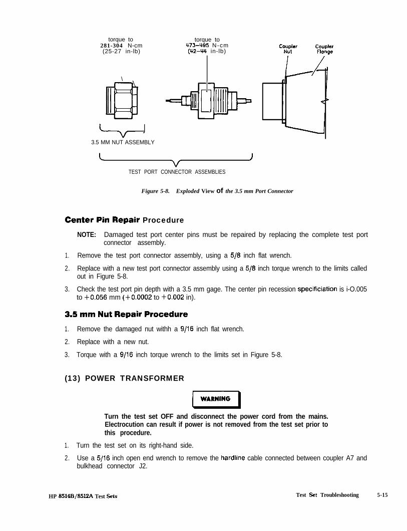
torque to281-304 N-cm(25-27 in-lb)
\
J3.5 MM NUT ASSEMBLY
torque to473495 N-cm(42-W in-lb)
c J
TEST PORT CONNECTOR ASSEMBLIES
Figure 5-8. Exploded View of the 3.5 mm Port Connector
Center Pin Repair Procedure
NOTE: Damaged test port center pins must be repaired by replacing the complete test portconnector assembly.
1. Remove the test port connector assembly, using a 5/8 inch flat wrench.
2. Replace with a new test port connector assembly using a 5/8 inch torque wrench to the limits calledout in Figure 5-8.
3. Check the test port pin depth with a 3.5 mm gage. The center pin recession specificiation is i-O.005to +0.056 mm (+0.0002 to +0.002 in).
3.5 mm Nut Repair Procedure1. Remove the damaged nut withh a 9/16 inch flat wrench.
2. Replace with a new nut.
3. Torque with a 9/16 inch torque wrench to the limits set in Figure 5-8.
(13) POWER TRANSFORMER
Turn the test set OFF and disconnect the power cord from the mains.Electrocution can result if power is not removed from the test set prior tothis procedure.
1. Turn the test set on its right-hand side.
2. Use a 5/16 inch open end wrench to remove the hardline cable connected between coupler A7 andbulkhead connector J2.
HP 85148/85l2A Test Sets Test Set Troubleshooting 5-15

3.
4.
5.
6.
7.
Unplug the transformer connector mating with connector J2 on the Al5 regulator board assembly.
Use a large pozi-driv screwdriver to remove the four screws and washers holding transformer Tlonto the rear panel.
Use a large pozi-driv screwdriver to remove the one screw holding the transformer angle bracket tothe main deck. Carefully remove the transformer from the test set and put it on the bench close tothe test set. The transformer wires soldered to line module FL1 are short, so do not pull on thetransformer too much.
Strip the heat shrink tubing off of the transformer wires soldered to line module FL1 and unsolderthem. Unsolder the transformer ground wire connected to the chassis side rail.
Remove transformer Tl. When replacing the transformer, refer to Figure 5-9, which illustrates thelocations of the various wires connected to line module FLl.
TO SlFRONT PANEL
ON/OFFSWITCH
’ BiACK/REOIGRM
\ -4
WHITE /CREY 7
TO Bl FAN
Figure 5-9. Wire Connections to Line Module FL1
TO TlTMNSFORMER
5-16 Test Set Troubleshooting HP 8514B/85l!JA Test Sets
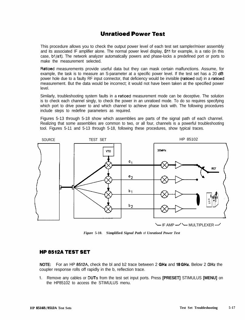
Unratioed Power Test
This procedure allows you to check the output power level of each test set sampler/mixer assemblyand its associated IF amplifier alone. The normal power level display, Sll for example, is a ratio (in thiscase, bl/al). The network analyzer automatically powers and phase-locks a predefined port or ports tomake the measurement selected.
Ratioed measurements provide useful data but they can mask certain malfunctions. Assume, forexample, the task is to measure an S-parameter at a specific power level. If the test set has a 20 dBpower hole due to a faulty RF input connector, that deficiency would be invisible (ratioed out) in a ratioedmeasurement. But the data would be incorrect; it would not have been taken at the specified powerlevel.
Similarly, troubleshooting system faults in a ratioed measurement mode can be deceptive. The solutionis to check each channel singly, to check the power in an unratioed mode. To do so requires specifyingwhich port to drive power to and which channel to achieve phase lock with. The following proceduresinclude steps to redefine parameters as required.
Figures 5-13 through 5-18 show which assemblies are parts of the signal path of each channel.Realizing that some assemblies are common to two, or all four, channels is a powerful troubleshootingtool. Figures 5-11 and 5-13 through 5-18, following these procedures, show typical traces.
a2
SOURCE TEST SET HP 85102
VI0
4
20MHz
Q1
3 cbl 0
TEST
b2 l +-L IF AMP -/ L MULTIPLEXER 2
Figure 5-10. Simplified Signal Path of Unratioed Power Test
HP 8512A TEST SET
NOTE: For an HP 8512A, check the bl and b2 trace between 2 GHz and 18GHz. Below 2 GHz thecoupler response rolls off rapidly in the b, reflection trace.
1. Remove any cables or DUTs from the test set input ports. Press [PRESET] STIMULUS [MENU] onthe HP85102 to access the STIMULUS menu.
HP 8514B/85l2A Test Sets Test Set Troubleshooting 5-17
2. a. HP8340/41 systems: press [STEP] on the HP85101 to set the source to step mode.
b. HP 8350B systems: press [SWEEP TIME] and use the entry keys to set the sweep time to200 ms.
al Test3. Press PARAMETER [MENU] [USER 1 al] to see the unratioed power trace.
For an HP 8512A, the trace level should decrease from -20 + 5 dB at low frequency to -35 t 5 dBat high frequency.
bl Reflection Test4. Connect an open (or a short) to port 1.
5. Press [USER 4 bl] and check that the trace for each is within the limits described above.
b2 Thru Test6. Connect a thru between port 1 and port 2 (connect pad to port 1 and test port return cable between
pad and port 2).
For an HP8512A, use a 20 dB system pad.
7. Press [USER 2 b2] and check that the trace is within the same limits.
8. If one or more channels appear faulty, refer to the procedure titled //Any User Channel Looks Bad atthe end of this section.
HP 85148 TEST SET
NOTE: For an HP 8514B, check the bl and b2 trace between 2 GHz and 20 GHz. Below 2 GHz thecoupler rolls off rapidly.
1. Press [PRESET] STIMULUS [MENU] on the HP85102 to preset the HP8510 and access the STIM-ULUS menu.
a. HP8340/41 systems: press [STEP] on the HP85101 to put the source in step mode.
b. HP8350B systems: press [SWEEP TIME] and use the entry keys to set the sweep time to200 ms.
Sampler Test2. To check all of the samplers in an S-parameter test set, first redefine the a2 and b2 phase lock and
drive paths:
Press PARAMETER [MENU] [User 3 a21 [REDEFINE PARAMETER] [DRIVE] [Port 21[PHASELOCK] [a21 [REDEFINE DONE] to redefine a2.
Press [User 2 b2] [REDEFINE PARAMETER] [DRIVE] [Port 21 [PHASELOCK] [a21 [REDEFINEDONE] to redefine b2.
3. Connect an open (or short) to port 1 and port 2.
5-18 Test Set Troubleshooting HP 8514B/85lZA Test Sets

4. Press [User 1 al], [User 2 b2], [User 3 a2], and [User 4 bl] to check the samplers indicated. Eachtrace should be within the following limits:
For an HP 8514B, the traces should decrease from -20 + 5 dB at low frequency to -27 + 5 dB athigh frequency.
NOTE: the RF signal paths are shown in Figure 5-12 through 5-18.
bl Thru Test5. Connect a thru (two RF cables) from port 1 to port 2.
6. Press PARAMETER [MENU] [USER 4 bl] [REDEFINE PARAMETER] [DRIVE] [PORT 21 [PHA-SELOCK] [a21 [REDEFINE DONE] to observe the bl power level trace through the path indicatedby Figure 5-12 through 5-18 bl thru.
b2 Thru Test7. Press Parameter [MENU] [USER 2 b2] [REDEFINE PARAMETER] [DRIVE] [PORT l] [PHA-
SELOCK] [al] [REDEFINE DONE] to observie the b2 power level trace through the path indicatedby Figure 5-12 through 5-18.
Next StepIf one or more channels look abnormal, refer to the procedure titled /fAny User Channels Look&d at theend of this section.
HP 8514BJ8512A Test Sets Test Set Troubleshooting 5-19
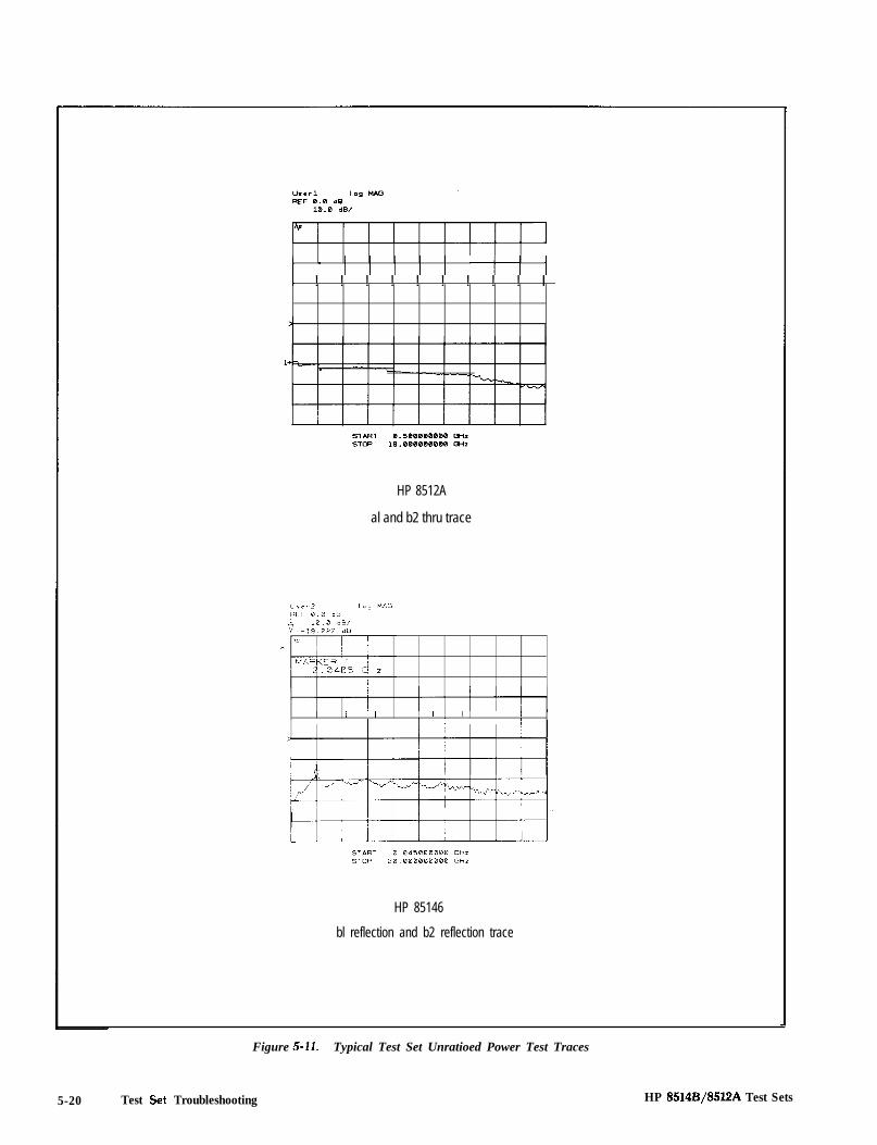
t i i i i i i iii 1I ! ! ! ! ! ! ! ! ! I
HP 8512A
al and b2 thru trace
, / / , , , , ,I I I I I I I I I
HP 85146
bl reflection and b2 reflection trace
Figure 5-11. Typical Test Set Unratioed Power Test Traces
5-20 Test Set Troubleshooting HP 8514B/85l2A Test Sets

NIC I
w I I I
al
COUPLER COUPLER
u P O R T 1 u P O R T 2
a2
COUPLER
[E
u P O R T 1
O P E N O R S H O R T
u P O R T 2 u P O R T 1 u P O R T 2
O P E N O R S H O R TII
b, Reflectionb, Reflection
Figure 5-12. User Signal Paths in Test Sets (1 of 2)
HP 8514B/8512A Test Sets Test Set Troubleshooting 5-21

F
I II Imxm L
COUPLER COUPLER5
1 J PORT I L J PORT 2
b, Thru
COUPLER COUPLER
I. J PORT I L J PORT 2
b, Thru
Figure 5-12. User Signal Paths in Test Sets (2 of 2)
5-22 Test Set Troubleshooting HP 8514B/8512A Test Sets

R E F - 2 2 . 0 6 dB -1 0 . 0 dB/
HP 8514Bf8512A Test Sets
3
S T A R T 0 . 0 4 5 0 0 0 0 0 0 GHzS T O P 2 0 . 0 0 0 0 0 0 0 0 0 GHz
Figure 5-13. Typical HP 8514B Option 002/003 a, Reflection Trace
D
a
(
r
COUPLER
u P O R T 1
Figure 13a. HP 8514B Option 002/003 aI Reflection Signal Path
Test Set Troubleshooting 5-23
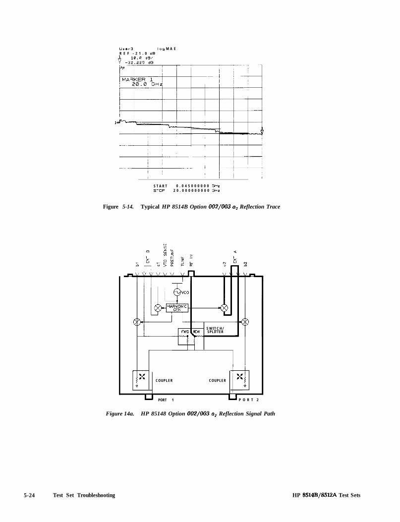
User3 log M A ER E F - 2 1 . 0 dB
S T A R T 0 . 0 4 5 0 0 0 0 0 0 GHzSTDP 2 0 . 0 0 0 0 0 0 0 0 0 GHr
Figure 5-14. Typical HP 8514B Option 002/003 ap Reflection Trace
COUPLER
- S W I T C H /w SPLITTER-
COUPLER
0x
u PORT 1 u P O R T 2
Figure 14a. HP 85148 Option 002/003 ap Reflection Signal Path
5-24 Test Set Troubleshooting HP 8514B/85l2A Test Sets

User2 log M A GR E F - 6 0 . 6 9 dB
1 0 . 0 dB/
HP 8514B/8512A Test Sets
S T A R T 0 . 0 4 5 0 0 0 0 0 0 GHzS T O P 2 0 . 0 0 0 0 0 0 0 0 0 GH7.
Figure 5-15. Typical HP 8514B Option 002/003 b, Reflection Trace
COUPLER COUPLER
/
u PORT 1
I IO P E N O R S H O R T
I
u P O R T 2
Figure 15a. HP 8514B Option 002/003 b, Reflection Signal Path
Test Set Troubleshooting 5-25

lJrcr4 log MAGREF -51.45 dB
t -,:y, “:;
START 0.045000000 GHzSTOP 20.000000000 GHr
Figure 5-16. Typical HP 8514B Option 002/003 b, Reflection Trace
illx
COUPLER COUPLER
I I
u P O R T 1 u P O R T 2
O P E N O R S H O R TII
Figure 160. HP 8514B Option 002/003 b, Rejiection Signal Path
5-26 Test Set Troubleshooting HP 8514F3/8512A Test Sets

User4 l o g M A GR E F - 5 0 . 0 dB
1
S T A R T 0 . 0 4 5 0 0 0 0 0 0 GHzS T O P 2 0 . 0 0 0 0 0 0 0 0 0 Gtiz
Figure 5-17. Typical HP 8514B Option 002/003 b, Thru Trace
C O U P L E R 1 I/’ 2 I
Figure 17a. HP 85148 Option 002/003 b, Thru Signal Path
HP 8514B/85l!2A Test Sets Test Set Troubleshooting 5-27

Urcr2 l o g M A GR E F 0 . 0 dB1 1 0 . 0 dB/v - 1 8 . 5 9 8 dB
S T A R T 0 . 0 4 5 0 0 0 0 0 0 GHzS T O P 2 0 . 0 0 0 0 0 0 0 0 0 GHz
Figure 5-18. Typical HP 8514B Option 002/003 b, Thru Trace
1
xCOUPLER COUPLER
LJ PORT I L J PORT 2
Figure Ma. HP 8514B Option 002/003 b, Thru Signal Path
5-28 Test Set Troubleshooting HP 8514B/85l2A Test Sets
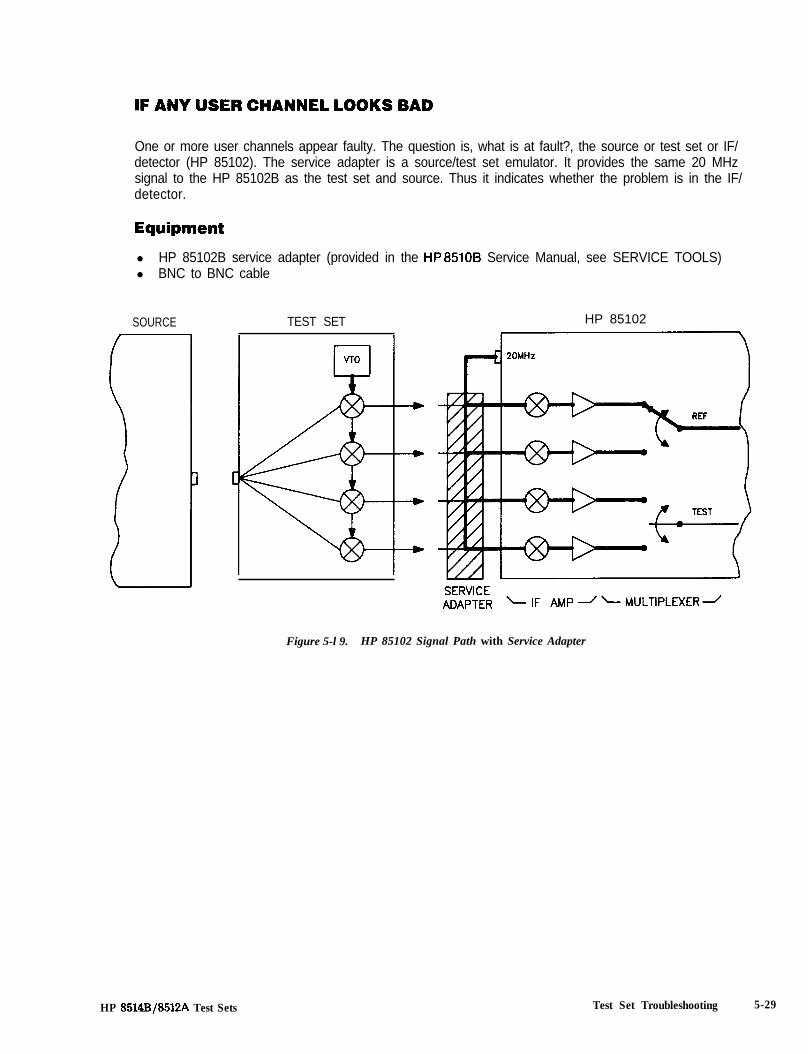
IF ANY USER CHANNEL LOOKS BAD
One or more user channels appear faulty. The question is, what is at fault?, the source or test set or IF/detector (HP 85102). The service adapter is a source/test set emulator. It provides the same 20 MHzsignal to the HP 85102B as the test set and source. Thus it indicates whether the problem is in the IF/detector.
Equipmentl HP 85102B service adapter (provided in the HP8510B Service Manual, see SERVICE TOOLS)l BNC to BNC cable
SOURCE TEST SET HP 85102
Figure 5-l 9. HP 85102 Signal Path with Service Adapter
HP 8514B/8512A Test Sets Test Set Troubleshooting 5-29
Service Adapter Procedure1. Connect the HP 851026 service adapter to the HP 85102B rear panel “20 MHz OUT” connector and
the “J2 IF-DISPLAY INTERCONNECT” connector.
2. Press [PRESET] [MARKER] STIMULUS [MENU] [STEP] PARAMETER [MENU] and each Usersoftkey to observe the unratioed power level of the User1 through User4 channels. The tracesshould be flat lines, quite close to each other, as indicated by the marker value (typically about-28+5 dB).
Service Adapter Conclusionsl If all of the channels look good (with the service adapter) and all looked bad in the unratioed power
test, the HP85101 and 85102 are working. The problem is probably source related. Refer to theSource Tests and Service Program sections of the Service Manual to continue troubleshooting theproblem.
l If all four User channels look bad (with the service adapter), suspect the 20 MHz signal from the A6clock board assembly. Refer to the paragraph titled HP85702 IF/Detector Tests in the ServiceProgram section to verify the 20 MHz output.
0 If one or more (but not all) channels look bad, troubleshoot the HP 85102 by refering to the ServiceProgram and Block Diagrams sections of the Service Manual. Then recheck the unratioed channelpower levels.
Single channel problems suggest the IF Mixer board corresponding to the User function (channelal, bl, al, or a2) is faulty. Refer to the Overall System Block diagram located in the Block Diagramssection of the Service Manual.
Multiple channel problems indicate the problem is most likely in the circuitry after the IF Mixerboards (for example, the IF amplifiers or synchronous detectors). Refer to the HP 85702A OverallBlock Diagram in the Block Diagrams section of the Service Manual.
Determine whether the failure is in the reference path or the test path.
Test the suspect board(s) using the procedures provided in the Service Program section.
Check the IF Amplifiers and Synchronous Detectors by swapping the reference and test boardassemblies (since they are identical) and seeing if the problem moves.
5-30 Test Set Troubleshooting HP 8514B/85l2A Test Sets
Section 6. Replaceable Parts
INTRODUCTION
This section contains information for ordering parts. Exchange Assemblies Available describes how toorder assemblies which are available on an exchange basis. Table 6-1 is a list of manufacturers (bycode number) and reference designations.
HP8514B replaceable parts are identified by Table 6-2 and Figures 6-l through 6-7.
HP8512A replaceable parts are identified by Table 6-3 and Figures 6-3, 6-4 and 6-8 through 6-10.
EXCHANGE ASSEMBLIES AVAILABLE
The items below are replaceable on a rebuilt exchange basis at a cost saving. They are not field-repairable. Defective assemblies must be returned for credit to realize the cost savings. Thus,assemblies required for spare parts stock should be ordered by the new assembly part number whichis included in the replaceable parts list of this section. See the parts list for the orderable part numbers.
l A2 IF multiplexer board assembly. A3 VT0 summing amplifier board assemblyl A4 HPIB board assemblyl A5 attenuator/switch driver assembly*l A6 couplerl A7 bias tee*. A8 coupler*
. A9l A10l Alll Al2l Al3l Al4
bias tee*sampler assembly (input bl)sampler assembly (input b2)sampler assembly (input al)sampler assembly (input a2)*VTO/driver assembly
l Al50 Al6l Al70 Al8
regulator board assemblystep attenuator*step attenuator*switch/splitter*
l HP 8514B only
HP 8514B/85lZA Test Sets Replaceable Parts 6-1
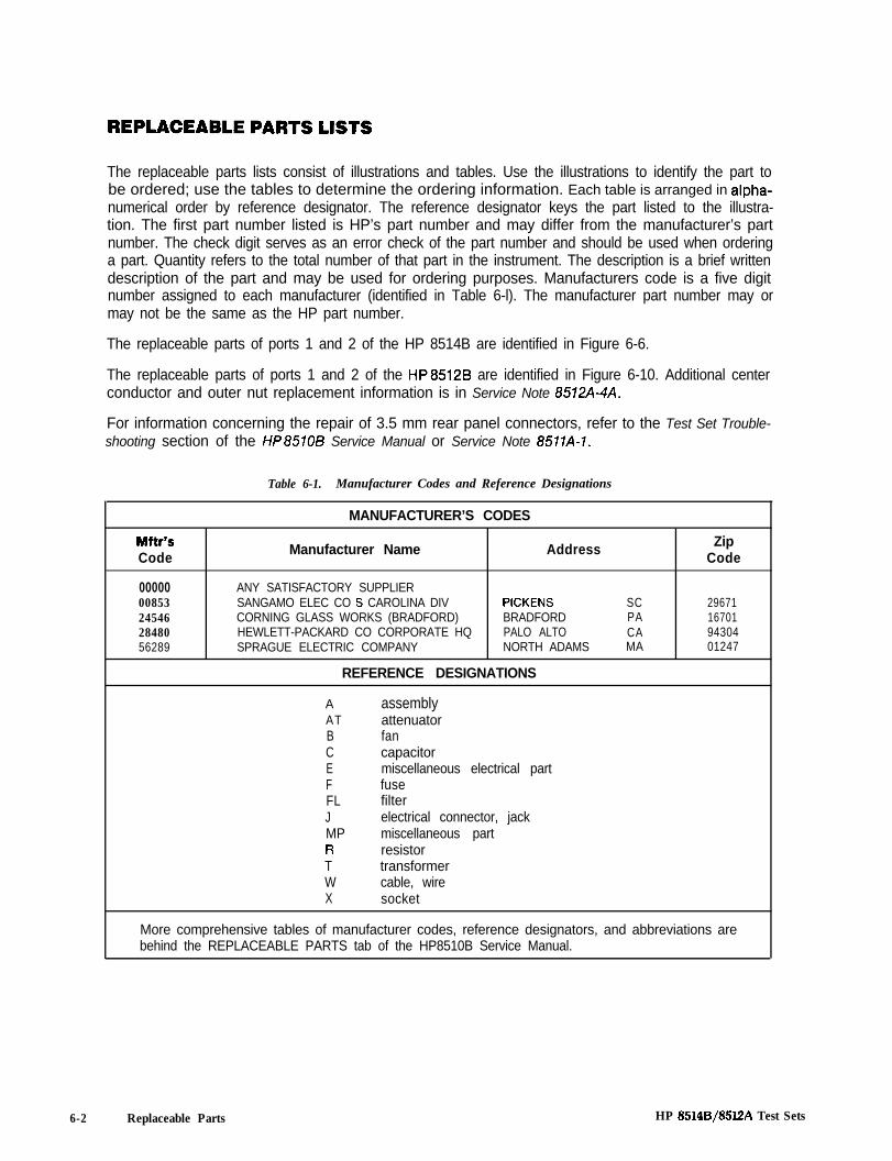
The replaceable parts lists consist of illustrations and tables. Use the illustrations to identify the part tobe ordered; use the tables to determine the ordering information. Each table is arranged in alpha-numerical order by reference designator. The reference designator keys the part listed to the illustra-tion. The first part number listed is HP’s part number and may differ from the manufacturer’s partnumber. The check digit serves as an error check of the part number and should be used when orderinga part. Quantity refers to the total number of that part in the instrument. The description is a brief writtendescription of the part and may be used for ordering purposes. Manufacturers code is a five digitnumber assigned to each manufacturer (identified in Table 6-l). The manufacturer part number may ormay not be the same as the HP part number.
The replaceable parts of ports 1 and 2 of the HP 8514B are identified in Figure 6-6.
The replaceable parts of ports 1 and 2 of the HP8512B are identified in Figure 6-10. Additional centerconductor and outer nut replacement information is in Service Note 8572A-4A.
For information concerning the repair of 3.5 mm rear panel connectors, refer to the Test Set Trouble-shooting section of the HP8510B Service Manual or Service Note 8511A-1.
Table 6-1. Manufacturer Codes and Reference Designations
MANUFACTURER’S CODES
Mftr’sCode Manufacturer Name Address Zip
Code
0000000853245462848056289
ANY SATISFACTORY SUPPLIERSANGAMO ELEC CO S CAROLINA DIV PICKENSCORNING GLASS WORKS (BRADFORD) BRADFORDHEWLETT-PACKARD CO CORPORATE HQ PALO ALTOSPRAGUE ELECTRIC COMPANY NORTH ADAMS
REFERENCE DESIGNATIONS
SC 29671PA 16701CA 94304MA 01247
A assemblyAT attenuatorB fanC capacitorE miscellaneous electrical partF fuseFL filterJ electrical connector, jackMP miscellaneous partR resistorT transformerW cable, wireX socket
More comprehensive tables of manufacturer codes, reference designators, and abbreviations arebehind the REPLACEABLE PARTS tab of the HP8510B Service Manual.
6-2 Replaceable Parts HP 85148/8512A Test Sets

Table 6-2. HP 8514B Replaceable Parts (1 of 4)
ReferenceDesignation
A lAlDSlAl DS2A2A3A4A5
A6
A7A7
A0 5180-2749 5
A9 50.66-7322 0A9 5086-6322 8
A10A10A l lA l lA l 2A l 2A l 3A l 3
5086-7402 75066-6402 55066-7402 75086.6402 75086.7402 75066-6402 75066-7402 75086.6402 7
A l 4 5086.7231 0A l 4 5086-6231 8
A l 5 38513-60007 5
A l 6A l 7
38340-60175 938340-60175 9
A18A18
5086.7324 25086-6324 0
A19 38513-60001 9
A19Cl 3180.2671 7A19C2 )180-2671 7A19C3 1180.2671 7A19C4 1180.2671 7A19C5 1160-4634 6A19C6 1160-4834 6A19Jl 1251-5745 4
A19J2A19J3
I251 -68661251-7939
42
A19J4A19J5A19J6A19J7AlSJfJA19J9A19RlA19R2A19R3A19R4A19R5A19R6A19XA2Al 9XA3Al 9XA4Al 9XA5Al 9XA6-A19XA14A19XA15r\20
1251-6868 41251-6666 41251.6868 41251-3825 71200-l 304 61200-l 304 61764-0015 73764-0015 71764-0016 81764-0016 61757-0394 01757-0394 01251.7882 41251.7882 4I251 -7002 41251-7082 4
1251-788218513-60006
AT1hT2tT3Bl31DSl
HP Part
08513-60005 31990.0658 61990-0858 6
06513-60008 fi08514-60029 208513-60011 1
5180.2749 5
5086-7322 05086-6322 6
3493cM93C
18513-200311160-43111990-0858
Cu Description
12
111
1
22
1
11111111
11
1
2
11
1
4
2
41
1222
2
5
1
11
112
BOARD ASSEMBLY. FRONT PANELLED-LAMP LUMdNT=15UCD IF=25MA-MAXLED-LAMP LUM-lNT=15UCD IF=25MA-MAXSEE FIGURE 4VT0 SUMMING AMPLIFIER BD ASSY (NEW)BOARD ASSEMBLY. HP IO (NEW?Al-rENUATOR/SWliCH DRiVER (NEW)
DIRECTIONAL COUPLER (NEW)
BIAS TEE, PORT 2 (NEW)BIAS TEE, PORT 2 (REBUILT)
DIRECTIONAL COUPLER 28460 5160-2749
BIAS TEE, PORT 1 (NEW) 28480 5086.7322BIAS TEE, PORT 1 (REBUILT) 28480 5086-6322
61 SAMPLER ASSY (NEW) 28480 5066-7402Bl SAMPLER ASSY (REBUILT) 28480 5086-640282 SAMPLER ASSY (NEW) 28480 5086-740282 SAMPLER ASSY (REBUILT) 28460 5066-6402Al SAMPLER ASSY (NEW) 28480 5066-7402Al SAMPLER ASSY (REBUILT) 20400 5086-6402A2 SAMPLER ASSY (NEW) 26480 5086.7402A2 SAMPLER ASSY (REBUILT) 28460 50866402
VTO/DRIVER (NEW)VlO/DRlVER (REBUILT)
2e480 5086-723126480 5086-6231
BOARD ASSEMBLY, REGULATOR 2e480 085 13-60007
STEP AnENUATOR. PORT 1 28480 08340-60175STEP ATTENUATOR, PORT 2 28480 06340-60175
SWITCH/SPLITTER (NEW) 28480 5086-7324SWITCH/SPLInER (REBUILT) 26480 5086-6324
BOARD ASSEMBLY, MOTHERTHE FOLLOWING PARTS ARE NOT SUPPLIEDWHEN A19 IS ORDERED: A19Cl. A19C2, A19C3. A19C4CAPACITOR-FXD .012F+75-10% BOVDC ALCAPACITOR-FXD .012F+75-10% 30VDC ALCAPACITOR-FXD .012F+75-10% 30VDC ALCAPACITOR-FXD .012F+75-10% 30VDC ALCAPACITOR-FXD .047UF zk 10% 1OOVDC CERCAPACITOR-FXD .047UF k 10% 1 OOVDC CERCONNECTOR 20-PIN M POST TYPE(A19Jl DOES NOT INCLUDE AlSMPl 8 A19MP2)CONNECTOR 5-PIN M POSTTYPECONN-POST TYPE .lOO-PIN-SPCG 14-CONT(A19J3 DOES NOT INCLUDE A19MP3)CONNECTOR 5-PIN M POST TYPECONNECTOR 5-PIN M POST TYPECONNECTOR 5-PIN M POST TYPECONNECTOR 5-PIN M POST NPEIC SOCKET 14 PINIC SOCKET 14 PINRESISTOR 560 5% 2W MO TC=0?200RESISTOR 560 5% 2W MO TC=0?200RESISTOR 1K 5%2W MOTC=O+POORESISTOR 1 K 5% 2W MO TC=0+200RESISTOR51.1 1%.125WFTC=OclOORESISTOR51.1 1%.125WFTC=O+lOOCONNECTOR-PC EDGE 2-ROWSCONNECTOR-PC EDGE P-ROWSCONNECTOR-PC EDGE P-ROWSCONNECTOR-PC EDGE P-ROWS
26460 08513-60001
00853 500123U030AC2A00653 500123U030AC2A00653 500123U030AC2A00853 500123U030AC2A28460 0160-483428480 0160-463428480 1251-5745
28480 1251-686826480 1251-7939
2848026480284802848028480284602848028480284602846024546245462848028480284802e480
1251-68681251-66681251-66681251-38251200-l 3041200-1304076440150764-00150764-00160764-0016Cd-l/8-TO-51Rl-FC4-l/8-TO-51Rl-F1251-76821251-76621251-76621251-7002
NOT ASSIGNEDCONNECTOR-PC EDGE P-ROWSBOARD ASSEMBLY, HPIB INTERCONNEC?
MISCELLANEOUS ELECTRICAL PARTS
3.5 MM 20 DB ATTENUATOR3.5 MM 20 DB AnENUATORSEE FIGURE 7FAN-TBAX 34-CFM 115V 50/60-HZ 1 .BKV-DIELCAPACITOR-FXD .022UF +80-20% 1OOVDC CERLED-LAMP LUM-lNT=15UCD IF=25MA-MAX
MfrCode
284602846028460
08513-6000519904656lSSLMS58
264602848028480
08513-6ooo6065 14-6002906513-60011
28460 5180-2749
284802e460
5086-73225086-6322
28480 1251-788228480 08513-60006
2846028460
8493c64930
4N833 08513-2003156289 C023BlOlH223Z-CDH28480 1990-0856
Mfr Part Number
HP 8514Bf85l2A Test Sets Replaceable Parts 6-3

Table 6-2. HP 8514B Replaceable Parts (2 of 4)
Reference HP Part cDesignation Number e
Lx2ElE2E3E4E5E6E7E8E9E l0El1E l2E l 3E l4E l5E l6E l7E l8El9E20E21E22E23E24E25E26E27E28E29E30E31E32E33E34E35E36E37E38E39E40E41E42E43E44E45E46E47E48FlF2F3FL1J6J8RlTlWl-w12w13w14w15W16w17W18w19w20w21w22iN23W24W25iN26
1990-08580360-00090360-00310360-00310362-02650362-026508513-000160360-16735021-35105021-35105021.35105021-35105021-35105061-53015061-53015061.53015061-53015061-530108513-2001608513-2001606513-2001608513.2001606513.2001606513-2001708513-2001706513.2001708513.2001706513-2001706513-2001608513-2001606513-2001638513.2001608513-200182110-07972110-079735050-2000195050-200012110-05652110-05651251-37201251-37201251-37201251.37201251-37201251-37201251-37201251.37201251-37201251-3720!l 1 O-001 2!llO-0012211 O-00023135.02171250-00831250-00631757-03943100-4616
16513-6013318513.60134
18513-60136
16513-60136
18513-6014016513-6014118513-6014218513-6014318513-6014418513-6014518513-60146
6-4 Replaceable Parts HP 8514B/85l2A Test Sets
631177294444499999222223333344444997799111111111111871
1,5
B9
1
3
7B9J123
-
QtY
5
5
5
5
2
112
11
11
1
1
1111111
Description
LED-LAMP LUM-lNT=lSUCD IF=PSMA-MAXTERMINAL-SLDR LUG PL-MTG FOR-#BSCRTERMINAL-CRIMP R-TNG #6 22-18-AWG REDTERMINAL-CRIMP R-TNG 116 22-16AWG REDCONNECTOR-SGL CONT SKT l.lCMM-BSC-SZCONNECTOR-SGL CONT SKT 1.14-MM-BSC-SZINSULATOR-BRACETERMINAL STRIP 6.TERM PHEN 1.5-IN-LCONTACT-FEMALECONTACT-FEMALECONTACT-FEMALECONTACT-FEMALECONTACT-FEMALE3.5MM BEAD-R AY3.5MM BEAD-R AY3.5Mt.d BEAD-R AY3.5MM BEAD-R AY3.5MM BEAD-R AYCONNECTOR NOSE-FCONNECTOR NOSE-FCONNECTOR NOSE-FCONNECTOR NOSE-FCONNECTOR NOSE-FCONN-BULKHEADCONN-BULKHEADCONN-BULKHEADCONN-BULKHEADCONN-BULKHEADCENTER CNDCT-BHDCENTER CNDCT-BHDCENTER CNDCT-BHDCENTER CNDCT-BHDCENTER CNDCT-BHDFUSEHOLDERFUSEHOLDERCONTACT CTR CONDCONTACT CTR CONDFUSEHOLDER CAP 12A MAX FOR ULFUSEHOLDER CAP 12A MAX FOR ULCONNECTOR-SGL CONT SKT .04-IN-BSC-SZ RNDCONNECTOR-SGL CONT SKT .041N-BSC-SZ RNDCONNECTOR-SGL CONT SKT .O.-IN-BSC-SZ RNDCONNECTOR-SGL CONT SKT .04-IN-BSC-SZ RNDCONNECTOR-SGL CONT SKT .04-IN-BSC-SZ ANDCONNECTOR-SGL CONT SKT .04-IN-BSC-SZ RNDCONNECTOR-SGL CONT SKT .04-IN-BSC-SZ RNDCONNECTOR-SGL CONT SKT .04-IN-BSC-SZ RNDCONNECTOR-SGL CONT SKT .041N-BSC-SZ RNDCONNECTOR-SGL CONT SKT .04-IN-BSC-SZ RNDFUSE .5A 250V NTD 1.25X.25 ULFUSE .5A 250V NTD 1.25X.25 ULFUSE 2.OA 250V NTD 1.25X.25 ULLINE MODULE-FILTEREDCONNECTOR-RF BNC FEM SGL-HOLE-FR 50-OHMCONNECTOR-RF BNC FEM SGL-HOLE-FR 50-OHMRESISTOR 51.1 1% .125W FTC=OtlOOPOWER XFMRSEE FIGURE 6-4CA AY A3Jl-A14JlCA AY A3J2-Jl l A7SEE FIGURE 6-4:A AY A3J5-Jl lA5SEE FIGURE 6-4CA AY A3J7-Jl l A6SEE FIGURE 6-4“A AY A3J4-A14J2)A AY A5J2-A18J4:AAY A5Jl-A18J3:A AY A5J3-Al&J63AAY AlZJ3-JllAl3AAY A13J3-JllA4>A AY AlOJ3-JllA2
MfrCode
284802848028480284802848028480284802848028480284802846028460284802848028480284802848028480284802848028480284802848028480284802846028460284802846028480284802846028480284802848028480284802848028480284602848028480284802848028480284602848028480284802848028480284602848028480284802454628480
1990-0858036040090360-00310380-00310362-02650362026508513-000180380-l 6735021-35105021-35105021-35105021-35105021-35105061-53015061-53015061-53015081.53015061-530108513-2001608513-2001608513-2001608513-2001608513-2001608513-2001708513-2001708513-2001708513-2001708513-2001708513-2001808513-2001808513-2001808513-2001808513-200182110-07972110-079785050-2000185050-20001211 O-0565211 O-05651251-37201251-37201251-37201251-37201251-37201251-37201251-37201251-37201251-37201251-37202110-00122110-00122110-00023135-02171250-0083I250-0083%-l/8-TO-51Rl-F31 W-461 6
28480 I851 3-6013328480 38513-60134
28480 18513-60136
28480 18513-60138
28480 18513-6014028480 )8513-8014128480 18513-6014228480 1851~6014328480 18513-8014428480 18513-8014528480 18513-60146
Mfr Part Number
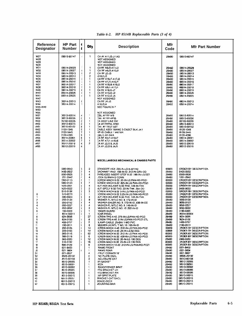
Table 6-2. HP 8514B Replaceable Parts (3 of 4)
Reference HP PartDesignatior Number
W27W28w29w30w31W32w33w34w35W36w37W38w39w40w41W42w43w44w45-w49w50-W56w57W58w59W60W61W62W63W64W65rv66iN67rrv68
IO111213I4I51617‘89
!O!l!2!3!4!5!617!8!9IO
08513-60147
08514-2002808514-2002708514-2001308514-2001408514-2001508514-2001608514-2001708514-2001808514-2001908514-2002606514-20025
08514-2001308514-20014
38513-6001438513-6003635102-60226)8513-60013~8510-601023120-I 3483120-34453120-4396)8514-2000116514-200021851 Z-2001 918512.20019
1380-0643)400-00021590-0926251-2942!360-0113!360-0123!420-0001!420-0022!510-0138!510-0270!580-00041050-01391050-01521050-02271050-0692II 60-030918514-00011624-00991624-0100400-0757‘190-0011‘200-0105ZOO-0165360-0115380-0119360-0333510-0192680-0129021-8403021-5804021-58378505-201328513-601568512-200058513-000016513-000028513-0000585 13-000068513-00015
)8513-0003718513-20013l8513-20015
QtY Description
1
11221111111
11111111112
2444174231
;4
i11
3782813146281216811422111111111
CAAYAIIJ3-JllA3NOT ASSIGNEDNOT ASSIGNEDNOT ASSIGNEDCA RF A8J3-All J2CA RF A6J3-AIOJZCA RF JZ-J3A18JlJ3CA RF A18J7-A17J2CA RF A7Jl-A16JlCARF A18J8-A16J2CARFASJI-A17JlCA RF A18J5-J7CA RF Al3J2-J2CA RF AlZJZ-J5NOT ASSIGNEDCA RF J4-J5A18JZJ4SEE FIGURE 6-7
NOT ASSIGNEDCBL AY RP-MBCBL AY RP-HPIBCA ASSY LINE SWCA AY FRPNL-MBDCBL AY TEST SETCABLE ASSY 18AWG 3-CNDCT BLK-JKlHP-IB CABLE 1 METERCBL C AY-SMACA RF A9Jl-A18J7:A RF A7Jl-A16J8“A AY J2J3 8 J4J5:A AY J2J3 8 J4J5
HISCELLANEOUS MECHANICAL 6 CHASSIS PARTS
STANDOFF-HEX ,255~IN-LG 6-32THD 00000SROMMET-RND .188-IN-ID ,312~IN-GRV-OD 28460rHREADED INSERT-STDF 6-32.188-IN-LG SSl 28480.OCK-SUBMIN D CONN 28480SCREW-MACH 6-32.25~IN-LG PAN-HD-POZI woo0SCREW-MACH 6-32.625-IN-LG PAN-HD-POZI woo0JUT-HEX-W/LKWR 6-32-THD .109-IN-THK woo0dUT-SPCLY 6-32-THD .23-IN-THK .354-OD 28480SCREW-MACH 8-32 3-IN-LG PAN-HD-POZI owooiCREW-MACH 8-32 3.25~IN-LG PAN-HD-POZI 00000JUT-HEX-W/LKWR 8-32-THD ,125~IN-THK wwoWASHER-FL MTLC NO. 8.172~IN-ID 28480VASHER-SHLDR NO. 8.172~IN-ID ,438~IN-OD 28480VASHER-FL MTLC NO. 6.149-IN-ID 28480IIASHER-FL MTLC NO. 10.202-IN-ID 28480‘INGER GUARD 284803EAR PANEL 28480iCREW-TPG 4-40.375-IN-LG PAN-HD-POZI 28480ICREW-TPG 4-40 S-IN-LG PAN-HD-POZI STL 28480:LAMP-CABLE .25-DIA I-WD PVC 28480VASHER-LK INTL T NO. 10.195-IN-ID 28480;CREW-MACH 4-40.312~IN-LG PAN-HD-POZI ooowICREW-MACH 4-40.25-IN-LG 82 DEG wwoICREW-MACH 6-32 ,312~IN-LG PAN-HD-POZI OWOO;CREW-MACH 6-32.438-IN-LG PAN-HD-POZI woo0iCREW-MACH 6-32 .25-IN-LG 100 DEG 28480iCREW-MACH 8-32.25-IN-LG 1 W DEG oooooLCREW-MACH IO-32.312~IN-LG PAN-HD-POZI oowo‘RAME FRONT 28480‘RAME REAR 28480iTRUT CORNER 18” 28480:ND PLATE ENCL 28480.NCLOSURE CKT 28480IFI GASKET 28480IECK 26460RANSFORMER BRKT 28480ITG BRACKET-LH 28480ITG BRACKET-RH 28480:AP SPRT PLATE 28480
3RACKET-CKT ENCL 264803RACE-DECK 28480MOUNTING BAR 26480
MfrCode Mfr Part Number
28480 08513-60147
2848028480284802848028480284802848028480284802848028480
08514-2002808514-2002708514-2001308514s2001408514-2001508514-2001608514-2001708514-2W1808514-2001908514-2002608514-20025
28480 08514-2001328480 08514-20014
264802848028480284802848028480284802648028480284802848028480
08513-6001408513-6003685102-6022608513-600130851 O-601 028120-13488120-34458120-439608514-2000108514-2000208512-2001908512-20019
ORDER BY DESCRIPTION0400-0002059049261251-2942ORDER BY DESCRIPTIONORDER BY DESCRIPTIONORDER BY DESCRIPTION2420-0022DRDER BY DESCRIPTIONORDER BY DESCRIPTIONORDER BY DESCRIPTION3050-01393050-01523050-0227305046923160-0309)8514-000043624-0099x24-01 001400-0757!190-Wll3RDER BY DESCRIPTION>RDER BY DESCRIPTION2RDER BY DESCRIPTIONIRDER BY DESCRIPTION!360-03333RDER BY DESCRIPTION3RDER BY DESCRIPTIONio21-8403io21-5804iO21-5837)8505-20132)8513-60156)851 Z-20005)8513-00001)8513-oooO2)8513-WOO5)8513-00006J8513-0001508513-0001608513-2001308513-20015
HP 8514B/85l2A Test Sets Replaceable Parts 6-5
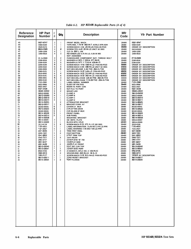
Table 6-2. HP 85148 Replaceable Parts (4 of 4)
Reference HP Part CDesignation Number D
434445464740495051525354555657585960616263646566676869707172737475767778795031323334353637383930313233343536
5021-6747 2 10460-0100 7 10520-0174 3 10624-0569 4 81400-1209 4 11450-0615 9 2
21 lo-05692190-00162190-01042200-01092200-01642260-00092360-01212510-00432510-01412950-00012950-01327121.23605021-09065021-34275021-3426D&340-4000208512-00008D6512-00009D6512-0001036512-0001136514-0000536513-0001735102-0004136513-0002235102-00041)6514-00026~6514-0001416514-0000616514-00007)6514-20005151 O-01 95rl20-46351121.2527jO21-6496jO40-72015041.6602iO40-7221iO62-3747iO61-9457iO61-9499)6513-00040)6513-00041~050-0105)360-0010!360-0127x%513-0001 716514-20024
3308
:26586662399034
0090575323I137333I3
2252
ii14425172221111221111111161124141121
i4112
QtY Description
FRONT BEZEL MACHTAPE-INDL l-IN-W ,002~IN-T ACRLC-XFR-ADHSCREW-MACH 2-56 .25-IN-LG PAN-I-ID-POZISCREW-TPG 440.25~IN-LG UNCT 62 DEGCLP CA .69D 1 .OWRETAINER-LED 0.75 IN LG; 0.36 IN WDNOT ASSIGNEDFUSEHOLDER COMPONENT NUT; THREAD M12.7WASHER-LK INTL T 3/6 IN ,377~IN-IDWASHER-LK INTL T 7;16 IN .439-IN-IDSCREW-MACH 4-40.436~IN-LG PAN-HD-POZISCREW-MACH 4-40.166-IN-LG UNCT 62 DEGNUT-HEX-W/LKWR 4-40.THD ,094~IN-THKSCREW-MACH 6-32.5-IN-LG PAN-HD-POZISCREW-MACH 6-32.312~IN-LG PAN-HD-POZISCREW-MACH 6-32.562~IN-LG PAN-HD-POZINUT-HEX-DEL-CHAM 3/6-32-THD .094-IN-THKNUT-HEX-DBL-CHAM 7/16-2%THD .094-IN-THKLABEL-SERIAL NUMBERSLEEV RF PIN POSWSHR-TS PORT CONNUT-FLG TS PORTMOUNT-LEDCLAMP ACLAMP BCLAMP CCLAMP DATTENUATOR BRACKETBRACKET-CONV AYCOVER-I.F. MUXCVR-ATTEN DRVRCVR BLANK-IF MUXFRONT PANELSUB PANELMOUNTING BRACKETSW MNTG PLATEBLOCK-MTG CPLRSCREW-MACH 6-32.375IN-LG 100 DEGLABEL-INFORMATION .75-IN-WD P-IN-LG PPRLABEL-WARNING l-IN-WD 7-IN-LG PPRTRIM FRNT HNDLFOOT-BOTTOMSTRIP TRIM TOP‘OOT-REAR:OVER BTM 16“ FM:OVER AY SIDEiANDLE AY FRONTrEST SET CVR TOP:OVER-SIDE PERFA’ASHER-FL MTLC NO. 4 .125-IN-IDSPACER-RND ,625~IN-LG .16-IN-IDSCREW-MACH 6-32.675~IN-LG PAN-HD-POZI:ONV-ASSEY BRACKET‘ORT FLANGE
MfrCode
28480 5021-674728480 0460-0100OOWQ ORDER BY DESCRIPTION28480 0624458928480 1400-120928480 1450-0615
204802848028480oooo0oooo0oowooooo0oooo0ooow0000000000284802e48020480284802848028480284802848028480284802848028480284802648028480284802848028480284802848028480284802848028480284802848028480284802848028480284802848028480000002848028480
2110-05692190-00162190-0104ORDER BY DESCRIPTIONORDER BY DESCRIPTIONORDER BY DESCRIPTIONORDER BY DESCRIPTIONORDER BY DESCRIPTIONORDER BY DESCRIPTIONORDER BY DESCRIPTIONORDER BY DESCRIPTION7121-23605021-09065021-34275021-342606340-4000208512-0000808512-00009D8512-00010D8512-0001106514-0000506513-0001785102-00041D6513-0002285102-0004136514-0002636514-0001436514-0000658514-0000738514-200052510-01951120-46357121.25275021-64965040-7201iO41-66025040.72215062-3747%l-9457iO61-949916513~00040)6513-00041~050-0105)380-0010IRDER BY DESCRIPTION~8513-00017)6514-20024
Yfr Part Number
6-6 Replaceable Parts HP &3514E3/8512A Test Sets

A5
A4
Al2
AT1(hidden)
A3
Al8 Al7 Al6 Tl
/A19
, A l 5
(hidden)
, A l 3
AT2
Allidden)
A6 A10 Al4 All A7 A8(hidAdSen) (hidden)
HP 8514B/8512A Test Sets
Figure 6-1. HP 8514B Top View Showing Locations of Major Assemblies
Replaceable Parts 6-7

055
(2 places)
(2 places) (2 places) (2 places) 63
J13 E33 E37 @ DS2 E34 Ej8 J-14(P/OA6- Fl* F2'See Figure 05. '
(P/O A8 -
6)See Figure
(2 places) 6)
El8 E23 J2 El9 E24 J3 E20 E25J4 E21 J5
E27 E22 J7 J8
(4 places) (4 places) (2 places)(2 places)
059
(2 places)'Not Visible
Figure 6-2. HP 8514B Miscellaneous Mechanical, Chassis, and Electrical Parts (1 of 5)
6-8 Replaceable Parts HP 8514B/85l2A Test Sets
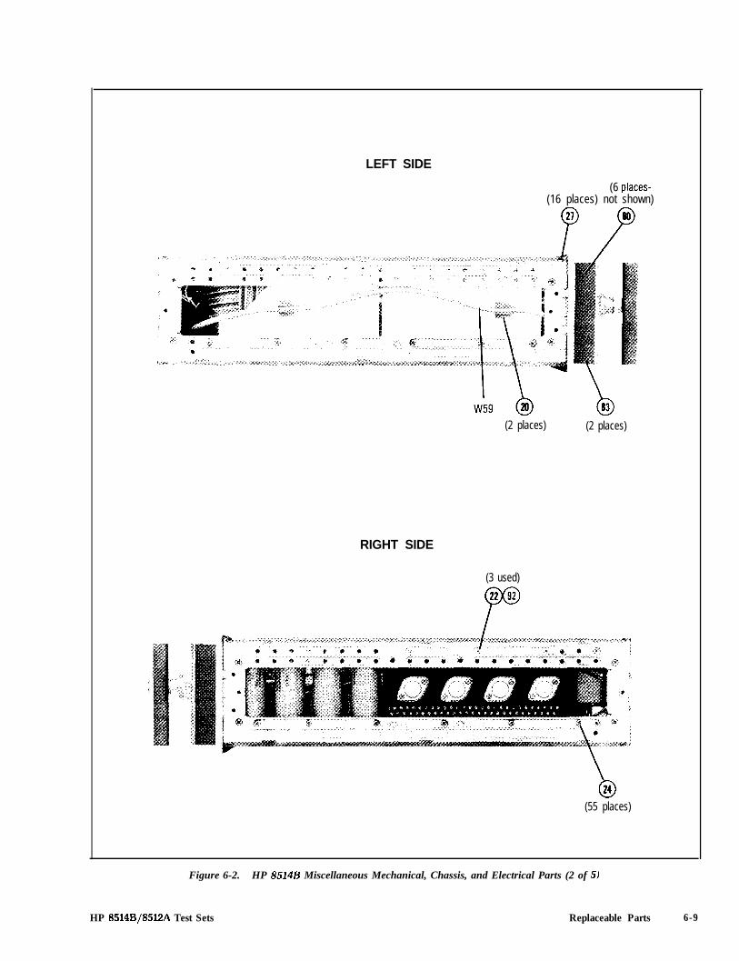
LEFT SIDE
(6 places-(16 places) not shown)
(2 places) (2 places)
RIGHT SIDE
(3 used)
\024
(55 places)
Figure 6-2. HP 8514B Miscellaneous Mechanical, Chassis, and Electrical Parts (2 of 5)
HP 8514B/85l2A Test Sets Replaceable Parts 6-9
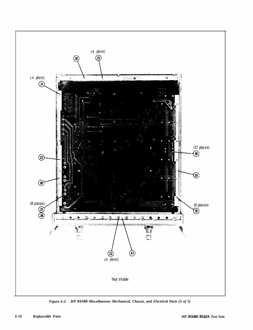
(6 places)
(4 places)
310,
a----
(37 place
018
-031
(8 places
‘019
(6 places)
‘Not Visible
9
‘1
Figure 6-2. HP 8514B Miscellaneous Mechanical, Chassis, and Electrical Parts (3 of 5)
6-10 Replaceable Parts HP 8514B/85l2A Test Sets

Figure 6-2. HP 8514B Miscellaneous Mechanical, Chassis, and Electrical Parts (4 of 5)
W43’Song)
W%(Short)
I
w33*(Long)
woQ7’(Short)
I
(4 places)
E39-E48
(4 places)
‘Not Visible
:es)
HP 8514B/8512A Test Sets Replaceable Parts 6-11

w41 '
E2' E13 ' E14 ' E17' E15' E16'@P~S)E$3' E 2 9 ' E32' E30' E31'
W66 Bl 7 l E9' W44 E12* W39 ElO' W34 Eli*
W32 ' ;,,,
'Not Visible
Figure 6-2. HP 8514B Miscellaneous Mechanical, Chassis, and Electrical Parts (5 of 5)
6-12 Replaceable Parts HP 8514B/8512A Test Sets

A19
1 I
I
0CI1
El
0C3
E l
0C2
El
IJ2IJ1 0Cl
Refer to Table 2 for additional information.
Figure 6-3. HP 8514B and HP 8512A Motherboard Component Location Diagram
HP 8514B/8512A Test Sets Replaceable Parts 6-13
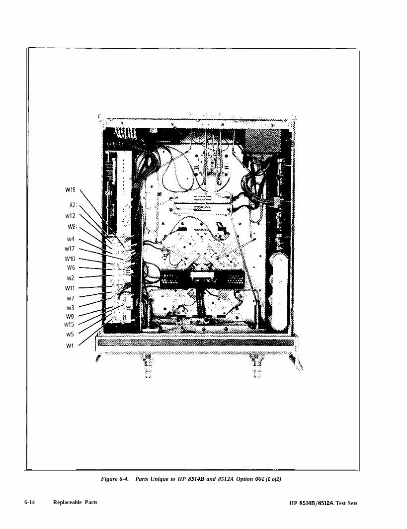
w19
A2
w12
W8
w4
w17
WlOW6
w2
Wll
w7
w3w9
w15
w5
Wl
6-14 Replaceable Parts
Figure 6-4. Parts Unique to HP 8514B and 8512A Option OOl(1 oj2)
HP 8514B/8512A Test Sets

Reference HPPart CDesignation Number D Dty Description Mfr
Code Mfr Part Number
A2 08513-60004 2 1A2
IF MULTIPLEXER BD AY (NEW) 28480 00513-6000406513-69004
iIF MULTIPLEXER BD AY 28480
Wl 06513-80121(REBUILT) 0851~6ooo4
1 A12J3-A2Jl CABLE AYw2
28480 08513-6012108513-60122 5 1 A13J3-A2J7 CABLE AY
w328480 08513-60122
08513-60123 6 1 Al OJ3-A2J4 CABLE AY 28480w4
08513-6012306513-60124 7 1 Al 1 J3-A2JlO CABLE AY 28480
w508513-M)124
06513-60125 8 1 A2J2-Jll Al CABLE AY 28480W6
08513-6012508513.60126 9 1 APJB-Jll A4 CABLE AY
w728480 08513-80126
08513-60127 0 1 A2J5-Jll A2 CABLE AYW6
28480 08513-6012708513-60128 1 A2Jll-JllA3CABLE AY 28480
w90851360128
08513.60129 : 1 A2J3-JlOAl CABLE AY 28480WlO
08513-6012908513-60130 5 1 A2J9-JlOA4 CABLE AY 28480
Wll08513-60130
06513-60131 6 1 A2J6-JlOA2 CABLE AY 28480 08513-60131w12 08513-60132 7 1 A2J12-JlOA3 CABLE AY 28480w13
0851360132SEE TABLE 6-2
w14 SEE TABLE 6-2w15 08513-60135 0 1 A3J3-JlOA7 CABLE AY 28460 08513-60135W16 SEE TABLE 6-2w17 06513-60137 2 1 A3J6-JlOA5 CABLE AY 28480W18
08513-60137SEE TABLE 6-2
w19 08513.60139 4 1 A3J&JlOA6 CABLE AY 28480 08513-60139
Figure 6-4. Parts Unique to HP 8514B and HP 8512A Option OOl(2 of 2)
HP 8514B/85l2A Test Sets Replaceable Parts 6-15

5 Places
N O T E : Insert flat washer (3) under cable clamp (2) as a spacer.
Reference HPPart CNumber D Qty Description Mfr
Besignation Code Mfr Part Number
Nl 06514-20022N2 06514-20023
: 1 A18Jl-A6J2 CABLE ASSY 26460 06514-200221 A16J7-ABJ2 CABLE ASSY 26460 06514.20023
I 2360.0113 2 5 MACHINE SCREW, 6/z2XO 25 26460 2360-0113
, 1400-0054 5 5 OPTION 002 CABLE CLAMP 26460 1400-0054
I 3050.0139 3 5 FLAT WASHER, 0.172 ID 28460 3050.0139
Figure 6-5. Parts Unique to HP 8514B Option 002
6-16 Replaceable Parts HP 8514B/85lZA Test Sets
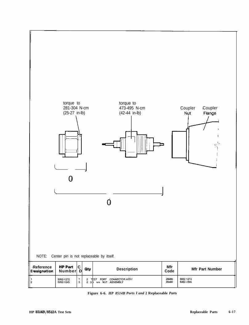
torque to281-304 N-cm(25-27 in-lb)
torque to473-495 N-cm(42-44 in-lb)
c J02
I J01
NOTE: Center pin is not replaceable by itself.
Coupler Coupler
Reference HPPart CIesignation Number D Qty Description Mfr
Code Mfr Part Number
5062.12725062.1245
7 2 TEST PORT CONNECTOR ASSY 26460 5062.12723 2 3.5 mm NUT ASSEMBLY 26460 5062-1245
Figure 6-6. HP 8514B Ports 1 and 2 Replaceable Parts
HP 8514BJ8512A Test Sets Replaceable Parts 6-17
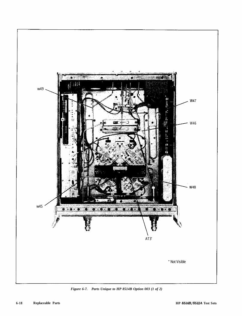
w49
w45
AT3’
* Not Visible
W46
w4a
6-18 Replaceable Parts
Figure 6-7. Parts Unique to HP 8514B Option 003 (1 of 2)
HP 8514B/85lZA Test Sets

Reference HP PartDesignation Number
w45 06514.20057W46 06514.20056w47 08514-20059W46 06514-20060w49 06514-20061AT3 3334ocz
Description
i
MfrCode
26460I-2646026460264602646026460
Mfr Part Number
06514-2005706514-2005606514-2005906514-2006006514-20061334ocz
Figure 6-7. Parts Unique to HP 8514B Option 003 (2 oj2)
HP 8514B/85l2A Test Sets Replaceable Parts 6-19

/
ir
;I\
w51 w50
Figure 6-8. HP 8514B Option 002/003 Parts (1 of 2)
6-20 Replaceable Parts HP 85148/8512A Test Sets

Reference HPPart CNumber D Dty Description Mfr
Designation Code Mfr Part Number
w45 SEE FIGURE 6-7w47 SEE FIGURE 6-7W46 SEE FIGURE 6-7w49 SEE FIGURE 6-7w50 06514-20090 3 1 CABLE RF A6 TO Al 1 26460 06514-20090w51 06514-20091 4 1 CABLE RF A6 TO A16 26460 06514-20091AT3 SEE FIGURE 6-7
Figure 6-8. Option 002/003 Ports (2 of 2)
HP 8514B/85l2A Test Sets Replaceable Parts 6-21

Table 6-3. HP 8512A Replaceable Parts (1 of 4)
Reference HP Part c
Designation Number t
A lAIDS1AlDS2A2A3A4A5
08513-600051990.08581990.0858
08513-6000808513.60002
A6 5080.0351 9
A7
A8
A9
A l 0A l 0
A l lA l l
A l 2 5086.7402 7A l 2 5086.6402 5
A l 3
A l 4A l 4
A l 5Al5
Al6
Al7
A18
419
419Cl419c2419c3419c4419c541903
419Jl
419J2419J3
419J4419J5419J6419J7419J8419J9419MPl
419MP2419MP3919Rl419R2!19R3419R4il9R5il9R6i19XA2\19XA3\19XA4\19XA5\19XA6-\19XAl4\19XAl5\20
5086.7402 75086.6402 5
5086.7402 75086.6402 5
5086.7231 05086-6231 8
38513.6000718515-69007
5086-7408
18513-60001
1180-26711180.26711180.26711180-2671)160-4834)160-4834
1251.5745
1251.68681251.7939
1251-6868I251 -68681251-68681251.38251200.05081200.0508‘251.5595
251.5595251.55951764.00151764-00151764.00161764.00161757-03941757-0394251.7882251.7882251-7882251-7882
251.78828513.60006
12
1
1
1
1
1
11
11
1
1
4
41
12
2
2
5
1
Description
BOARD ASSEMBLY, FRONT PANEL 28480 08513-60005LED-LAMP LUM-lNT=l5UCD IF=25MA-MAX 28480 1990-0858LED-LAMP LUM-lNT=15UCD IF=25MA-MAX 28480 1990.0858SEE FIGURE 4BOARD ASSEMBLY, VT0 SUMMING AMPLIFIERBOARD ASSEMBLY, HP IBNOT ASSIGNED
28480 08513-6000828480 08513-60002
DIRECTIONAL COUPLER(7mm cmnector IS replaceable: see Flgure 9)
28480 5080-0351
NOT ASSIGNED
NOT ASSIGNED
NOT ASSIGNED
81 SAMPLER ASSEMBLY (NEW) 28480 5086-7402Bl SAMPLER ASSEMBLY (REBUILT) 28480 5086-6402
82 SAMPLER ASSEMBLY (NEW) 28480 5086.740282 SAMPLER ASSEMBLY (REBUILT) 28480 5086-6402
Al SAMPLER ASSEMBLY (NEW) 28480 5086.7402Al SAMPLER ASSEMBLY (REBUILT) 28480 5086.6402
NOT ASSIGNED
no/DRIVER (NEW)VTO/DRIVER (REBUILT)
28480 5086.723128480 5086-6231
REGULATOR BOARD ASSEMBLY 28480 38513-60007REGULATOR BOARD ASSEMBLY 28480 38515.69007
NOT ASSIGNED
NOT ASSIGNED
POWER SPLITTER 28480 5086-7408
BOARD ASSEMBLY. MOTHERTHE FOLLOWING PARTS ARE NOT SUPPLIEDrVHEN A19 IS ORDERED:419Cl. Al9C2. A19C3. A19C4;APACITOR-FXD .012F+75-10% JOVDC AL“APACITOR-FXD .012F+75-10% JOVDC AL“APACITOR-FXD .012F+75-10% BOVDC AL3APACITOR-FXD .012F+75-10% 30VDC ALZAPACITOR-FXD .047UF k 10% 1OOVDC CER;APACITOR-FXD .047UF t 10% 1OOVDC CER
28480 )8513-60001
00853 j00123U030AC2A00853 j00123U030AC2A00853 SO01 23U030AC2A00853 i00123U030AC2A28480 1160.483428480 1160-4834
ZONNECTOR 20-PIN M POST TYPEA19Jl DOES NOT INCLUDE Al9MPl 8 Al9MP2)ZONNECTOR 5.PIN M POST TYPE:ONN-POST TYPE .lOO-PIN-SPCG 14-CONTA19J3 DOES NOT INCLUDE Al9MP3):ONNECTOR 5-PIN M POST TYPE:ONNECTOR 5-PIN M POST TYPE:ONNECTOR 5-PIN M POST TYPE:ONNECTOR 5.PIN M POST TYPESOCKET-IC 14.CONT DIP-SLDR;OCKET-IC 14.CONT DIP-SLDR‘OLARIZING KEY-POST CONN
28480 1251-5745
28480 1251.686828480 1251.7939
28480284802848028480284802848028480
1251-68681251-6868‘251-6868251.3825200-0508200-0508251-5595
‘OLARIZING KEY-POST CONN 28480‘OI-ARIZING KEY-POST CONN 284803ESISTOR 560 5% 2W MO TC=Oi200 28480?ESISTOR 560 5% 2W MO TC=0+200 284803ESISTOR 1K 5% 2W MO TC=0*200 28480IESISTOR 1K 5% 2W MOTC=0+200 284803ESISTOR51.1 1%.125WFTC=OklOO 24546?ESISTOR 51.1 1% .125W FTC=02 100 24546:ONNECTOR-PC EDGE P-ROWS 28480:ONNECTOR-PC EDGE P-ROWS 28480:ONNECTOR-PC EDGE P-ROWS 28480:ONNECTOR-PC EDGE P-ROWS 28480
251.5595251-55951764-00151764-00151764-00161764.0016:4-l/8-TO-51Rl.F:4-l/8-TO-51Rl-F251.7882251-7882251-7882251-7882
JOT ASSIGNED:ONNECTOR-PC EDGE P-ROWSSOARD ASSEMBLY, HPIB INTERCONNECl
MfrCode
28480 251-788228480 18513.60006
Mfr Part Number
6-22 Replaceable Parts HP 8514B/85l2A Test Sets
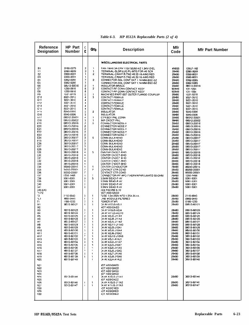
Table 6-3. HP 8512A Replaceable Parts (2 of 4)
Reference HP Part cDesignation Number c
BlElE2E3E4E5E6E7E8E9El0El1El2El3El4El5El6El7El8El9E20E21E22E23E24E25E26E27E28E29E30E31E32E33E34E35E36E37E38E39E40E41f42-E43-1 -F2-3‘LlriIV1N2N3N4N5N6N7N8N9NIONilN12N13N14N15N16N17NIBN19N20
N21N22N23n/24Y24Y25Y26Y27Y28Y29Y30
3160-0273 20360-0009 30360.0031 10360-0031 10362-0265 70362-0265 708513-00018 21250-0816 81250-0816 81531-0278 25021.351 LI 45021.3510 45021.3510 45021-3510 45021-3510 45040.0306 05040-0306 008512-20001 408512-20002 508513-20016 208513-20016 208513-20016 238513-20016 238513-20016 238513-20017 338513-20017 3~8513-20017 318513-20017 318513-20017 3)8513-20018 418513-20018 418513.20018 418513-20018 418513-20018 435040-20015 135050.20001 715050-20001 71250.1466 5jO61-5301 35061.5301 35061.5301 3iO61-5301 3
!l IO-00431960-0443il80-123318513-60121
)8513-60123)8513-6012416513-60125)8513-60126)8513-6012718513.60128I851 3-6012918513-60130)8513-6013118513.6013218513-60133~8513-60134I851 3-6013518513-6013618513-6013718513-6013818513-6013918513-60140
3733II>
51I
331I,
II
‘8513-60144
‘8513.601468513.60147
QtY Description
112
2
12
15
2
115
5
5
12
15
1111
111111111111111111
1
11
MISCELLANEOUS ELECTRICAL PARTS
FAN-TBAX 34-CFM 115V 50/60-HZ 1 .BKV-DIELTERMINAL-SLDR LUG PL-MTG FOR-#6-SCRTERMINAL-CRIMP R-TNG W6 22-16-AWG REDTERMINAL-CRIMP R-TNG #6 22.16.AWG REDCONNECTOR-SGL CONT SKT 1.14-MM-BSC-SZCONNECTOR-SGL CONT SKT 1.14-MM-BSC-SZINSULATOR-BRACECONTACT-RF CONN CONTACT ASSYCONTACT-RF CONN CONTACT ASSYMACHINED PART-SST OUTER FLANGE-COUPLERCONTACT-FEMALECONTACT-FEMALECONTACT-FEMALECONTACT-FEMALECONTACT-FEMALEINSULATORINSULATORCTR BDY PNL CONNINR CNDCT-PNLCONNECTOR NOSE-FCONNECTOR NOSE-FCONNECTOR NOSE-FCONNECTOR NOSE-FCONNECTOR NOSE-FCONN-BULKHEADCONN-BULKHEADCONN-BULKHEADCONN-BULKHEADCONN-BULKHEADCENTER CNDCT-BHDCENTER CNDCT-BHDCENTER CNDCT-BHDSENTER CNDCT-BHDZENTER CNDCT-BHDSENTERCONDUCTORSONTACT CTR COND30NTACT CTR COND:ONNECTOR-RF APC-7 HERMAPHR UNMTD 50-OHM3.5MM BEAD-R AY3.5MM BEAD-R AY3.5MM BEAD-RAY3.5MM BEAD-RAYSEE FIGURE 6-10UOT ASSIGNED-USE 1.5A 250V NTD 1.25X.25 UL-INE MODULE-FILTERED‘OWER XFMR:A AY A12J3-A2Jl\10T ASSIGNED:A AY AlOJ3-A2J4;AAY AllJ3-A2JlO:A AY A2J2-Jll Al:A AY A2J8-Jll A4:A AY A2J5-Jl lA2:AAY A2Jll-JllA3:A AY A2J3-JIOAI:A AY A2J9-JlOA4:A AY A2J6-JlOA2:AAY A2J12-JlOA3:AAY A3Jl-A14Jl:A AY A3J2-Jl l A7:A AY A3J3-Jl OA7:A AY A3J5-Jll A5:A AY A3J6-JlOA5:A AY A3J7-Jl lA6:A AY A3J8-JlOA6:A AY A3J4-A14J2
JOT ASSIGNEDJOT ASSIGNEDJOT ASSIGNEDJOT ASSIGNED:A AY A12J3-JIIAIJOT ASSIGNED:A AY AIOJB-Jl lA2:AAYAllJS-JIIAB10T ASSIGNED10T ASSIGNED10T ASSIGNED
MfrCode
4N8332848028480264802848028480284809D9499D949284802848028480284802848028480284802648028480284802848026480284802848028480284802848028480284802848028480284802848028480284802848028480284802848028480284802848028480
126LF-1820360-OOO30360-00310360-00310362-02650362-026508513-00018131-1054131-I 0541531-02785021.35105021-35105021-35105021-35105021-35105040-03065040-030608512-2000108512-2000208513-2001608513-2001608513-2001608513-2001608513-2001608513-2001708513-2001708513-2001708513-2001708513-2001706513-2001808513-2001808513-2001808513-2001808513-2001885040-2001585050-2000185050-200011250-I 4665061-53015061-53015061-53015061-5301
28480 211 O-004328480 0960444328480 5180-123328480 08513-60121
28480 08513-6012326480 08513-6012428480 08513-6012528480 08513-6012628480 08513-6012728480 08513-6012828480 08513-6012928480 08513-6013028480 D8513-6013126480 08513-6013228480 D6513-6013326480 08513-6013428480 38513-6013528480 38513-6013628480 38513-6013728480 38513-6013828480 38513-6013928480 38513-60140
28480 )8513-60144
28480 18513-6014628480 18513-60147
Mfr Part Number
HP 8514Bj85l2A Test Sets Replaceable Parts 6-23

Table 6-3. HP 8512A Replaceable Parts (3 of 4)
Reference HP Part c
Designatior Number c
w31W32w33w34w35W36w37W38w39w40-W48w49w50w51W52w53w54w55vV56N57A’58N59N60N61N62N63N64
67
14I5I61718191011.23456
06512-20011 f 10851 Z-2001 2 , 108512-20006 c 108513-20020 t 106513-20021 c 106513-20022 C 10851 Z-2001 7 i 1
08512-20019 4 2
08512-20019 4
06513-60014 4 108513-60036 0 185102.60193 5 108513.60013 3 10851 O-601 02 8 18120.1348 5 18120.3445 7 16120.4396 9 106513-60005 3 1
3380.06431400-00023590-09261251-2942!360-0113!360-0123!420-0001?420-0022!51 o-01 36!510-0270!580-00033050-01393050-01521050.02271050.0692II 60-030918514-000041624-0099)624-01001400.0757!190-0011izoo-0105!200-0165!360-0115!360-0119!360-0333!510-0192!680-01291020.88031020-88041020-883718505-2013216505-20163
0851 Z-2000508513-0000136513-0000238513-0000538513-00006)8513-0001538513-00016~8513-2001318513-2001535102.200541460-0100!200-01651400.1209
32072453315533357I55311III,I>
,I183478909137s4
24443651314944311
378289
22556121681142211111111111
1
QtY Description
CA AY A6J3-AlOJ2CAAYABJI-AllJ2CA AY AIZJZ-J4CA RF AlBJ3/PRT 1CA RF AlBJZ/PRT 2CA AY AlBJl/RFCA AY A6J2-J2NOT ASSIGNEDCA AY J2J3 8 J4J5
NOT ASSIGNEDCA AY J2J3 8 J4J5NOT ASSI;NEDNOT ASSIGNEDNOT ASSIGNEDNOT ASSIGNEDNOT ASSIGNEDNOT ASSIGNEDNOT ASSIGNEDCBL AY RP-MBCBL AY RP-HPIBCA ASSY LINE SWCA AY FRPNL-MBDCBL AY TEST SETCABLE ASSY 18AWG 3.CNDCT BLK-JKTHP-16 CABLE 1 METERCBL C AY-SMABD AY FRONT PNL
MISCELLANEOUS MECHANICAL & CHASSIS PARTS
STANDOFF-HEX 255.IN-LG 6-32THDGROMMET-RND ,168.IN-ID 312.IN-GRV-ODTHREADED INSERT-STDF 6-32 ,188.IN-LG SSTLOCK-SUBMIN D CONNSCREW-MACH 6.32 .25-IN-LG PAN-HD-POZISCREW-MACH 6-32.625-IN-LG PAN-HD-POZINUT-HEX-W/LKWR 6.32.THD .109-IN-THKYUT-SPCLY 6.32.THD .23-IN-THK ,354.ODSCREW-MACH 6-32 3-IN-LG PAN-HD-POZISCREW-MACH 8-32 3.25.IN-LG PAN-HD-POZIVUT-HEX-W/LKWR 8.32.THD .125-IN-THKNASHER-FL MTLC NO. 8.172.IN-IDA’ASHER-SHLDR NO. 8 .172-IN-ID ,436.IN-ODNASHER-FL MTLC NO. 6.149.IN-IDNASHER-FL MTLC NO. 10.202-IN-ID‘INGER GUARD3EAR PANELSCREW-TPG 4-40 ,375~IN-LG PAN-HD-POZISCREW-TPG 4-40 .5-IN-LG PAN-HD-POZI STL:LAMP-CABLE .25-DIA l-WD PVCNASHER-LK INTL T NO. 10 ,195~IN-IDSCREW-MACH 4-40 ,312~IN-LG PAN-HD-POZISCREW-MACH 4-40 .25-IN-LG 82 DEGSCREW-MACH 6.32.312.IN-LG PAN-HD-POZISCREW-MACH 6.32.438-IN-LG PAN-HD-POZISCREW-MACH 6-32.25~IN-LG 100 DEGSCREW-MACH 8-32.25.IN-LG 100 DEGSCREW-MACH IO-32.312-IN-LG PAN-HD-POZI-RAME FRONT:RAME REARSTRUT CORNER 18”iND PLATE ENCL
;‘NCLOSURE CKTRFI GASKETDECKTRANSFORMER BRK-IMTG BRACKET-LHMTG BRACKET-RHCAP SPRT PLATEBRACKET-CKT ENCLBRACE-DECKMOUNTING BAR=RONT BEZEL MACHTP ACRLC-XFR-A 1SCREW-MACH 4-40.25.IN-LG 82 DEG3LP CA .69D 1 .OW
MfrCode Mfr Part Number
26480 0851 Z-2001 126460 08512-2001226480 08512-2000628460 08513-2002026480 08513-2002128480 08513-2002228480 0851 Z-2001 7
28480 08512-20019
26480 08512-20019
284602848028480264802848028480284802846028460
08513-6001408513.6003685102.6019308513-6001308510-601026120-l 3486120-34456120.439608513-60005
0000028480284802648000000000000000028480000000000000000284802848028480264604N833284802848028480284802848000000000000000000000264800000000000284802848028480264802848028480284802848028480264802848026480284802848028480264800000028480
3RDER BY DESCRIPTION3400-00021590-09261251-29423RDER BY DESCRIPTION3RDER BY DESCRIPTION3RDER BY DESCRIPTION2420.0022)RDER BY DESCRIPTIONIRDER BY DESCRIPTIONIRDER BY DESCRIPTION3050-0139%050-0152$050.02271050-069212601-43 UL VERSION)8514-00004)624-0099)624-0100400-0757!l go-001 1)RDER BY DESCRIPTIONIRDER BY DESCRIPTIONIRDER BY DESCRIPTIONIRDER BY DESCRIPTION!360-0333IRDER BY DESCRIPTION)RDER BY DESCRIPTION~020-8803sO20-8804‘020-8837~8505-20132
~8505-2016338512-20005~8513-00001)8513-0000218513-0000518513-00006~8513-00015)8513-0001618513-2001318513-2001535102-200541460-01003RDER BY DESCRIPTION1400-l 209
6-24 Replaceable Parts HP 85148/85l2A Test Sets

Table 6-3. HP 8512A Replaceable Parts (4 of 4)
Reference HP Part CDesignation Number c
4748495051525354555657585960616263646566676869707172737475767778798061626384658697
2190-0104 C 52200-0109 E 12360-0121 2 22510-0141 5 42950.0132 E 56960.0001 3 27121-2380 e 15021.0906 6 65021-3427 2 25021.3428 3 208512-00001 2 108512-00008 9 20851 Z-00009 0 108512-00010 3 208512-00011 4 108513-00017 1 208513-00019 3 108513-00027 3 108514-00002 5 108514-20005 0 1
85102-00041 6 12510-0195 9 67120.4835 0 17120-5911 5 1
5020.8896 75040-7201 85040.7202 95040.7221 25060.9847 45060.9857 65060.9899 638513-00021 7~8513-00025 11380-0010 83050-0105 5!360-0127 818513-00017 I
241411211431
Qtl Description
WASHER-LK INTL T 7/16 IN .439-IN-IDSCREW-MACH 4-40.438.IN-LG PAN-HD-POZISCREW-MACH 6-32 .5-IN-LG PAN-HD-POZISCREW-MACH 8.32.562~IN-LG PAN-HD-POZINUT-HEX-DBL-CHAM 7/16-28.THD ,094~IN-THKPLUG-HOLE DOME-HD FOR .375-D-HOLE STLLABEL-SERIAL NUMBERSLEEV RF PIN POSWSHR-TS PORT CONNUT-FLG TS PORTFRONT PANELCLAMP ACLAMP BCLAMP CCLAMP DBRACKET-CONV AYCOVER-I.F. MUXCVR BLANK-IF MUXSUB PANELBLOCK-MTG CPLRNOT ASSIGNEDCOVER-BLANK Al6SCREW-MACH 8.32.375.IN-LG 100 DEGLABEL-INFORMATION .75-IN-WD P-IN-LG PPRLABEL-WARNING I-IN-WD 7-IN-LG PPRNOT ASSIGNEDNOT ASSIGNEDNOT ASSIGNEDTRIM FRNT HNDLFOOT-BOTTOMSTRIP TRIM TOPFOOT-REARCOVER BTM 18” FMCOVER AY SIDEHANDLE AY FRONTTEST SET CVR TOP30VER-SIDE PERFSPACER-RND .625-IN-LG .18-IN-IDNASHER-FL MTLC NO 4 .125-IN-IDSCREW-MACH 6-32 ,875.IN-LG PAN-HD-POZI‘ONV-ASSEY
MfrCode
28480 2190-010400000 ORDER BY DESCRIPTION00000 ORDER BY DESCRIPTION00000 ORDER BY DESCRIPTION00000 ORDER BY DESCRIPTION28480 6960-000128480 7121-238028480 5021-090628480 5021-342728480 5021-342828480 06512-0000128480 08512-0000828480 0851 Z-WOO928480 0851 Z-0001 028480 0851 Z-0001 128480 08513-0001728480 08513-0001928480 08513-0002728480 D8514-0000228480 08514-20005
28480 85102-0004128480 2510-019528480 7120-483528480 7120-5911
28480284802848028480284802848028480284802848028480284800000028480
5020-88965040.72015040-72025040-72215060.9847iO60-98575060-989918513.0002118513.00025)380-00101050-0105IRDER BY DESCRIPTION18513-00017
Mfr Part Number
HP 8514B/85l2A Test Sets Replaceable Parts 6-25

A20(hidden)
A19Al8 (on underside) Tl
A4 Al5
Al2 AT4(hidden)
AT2 c4
c3
A3c2
(hitlen)A6 A10 Al4 Al l
See Figure 3for parts unique to Option 001.
Figure 6-9. HP 8512A Top View Showing Locations of Major Assemblies
6-26 Replaceable Parts HP 8514Fi/8512A Test Sets
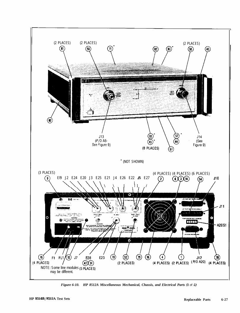
(2 PLACES) (2 PLACES) (2 PLACES)
* (NOT SHOWN)
(3 PLACES) (4 PLACES) (4 PLACES) (6 PLACES)El9 J2 E24 E20 J3 E25 E21 J4 E26 E22 J5 E27
\\\\\\ \ \ I I I / P P
NOTE: Some line modules (5 PLACES)may be different.
Figure 6-10. HP 8512A Miscellaneous Mechanical, Chassis, and Electrical Parts (1 of 5)
HP 8514B/85l2A Test Sets Replaceable Parts 6-27
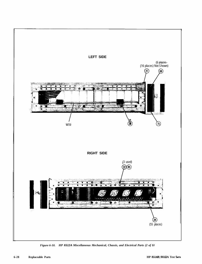
LEFT SIDE
(6 places-(16 places) Not Shown)
RIGHT SIDE
bm
(3 used)
(55 places)
Figure 6-10. HP 8512A Miscellaneous Mechanical, Chassis, and Electrical Parts (2 of 5)
6-28 Replaceable Parts HP 8514B/85l2A Test Sets

(6 places)
OL31
(4 places)
o--22
c-30
@w-(8 places)
38 259 9
018
(37 places)
-037
00(6 places)
‘Not Visible
‘019
(8 places)
Figure 6-10. HP 8512A Miscellaneous Mechanical, Chassis, and Electrical Parts (3 of 5)
HP 8514B/8512A Test Sets Replaceable Parts 6-29

w49 w39
6h m(Not (Not
Shown) W34 W36 W35 Shown) W37
(Held to (1 Used)Coupler by4 Ea. 50 *)0
*Not Visible
(12 places)
Figure 6-10. HP 8512A Miscellaneous Mechanical, Chassis, and Electrical Parts (4 of 5)
6-30 Replaceable Parts HP 8514B/85lZA Test Sets
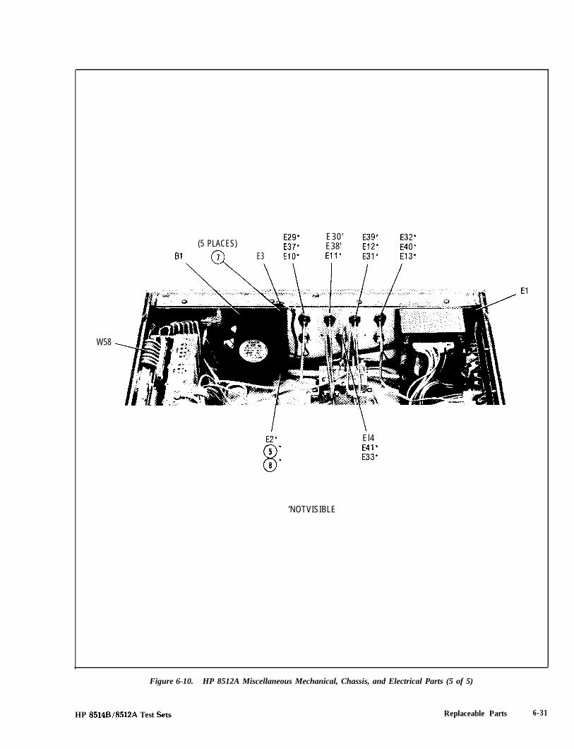
(5 PLACES)E29* E30' E39* E32*E37' E38' E12* E40*
Bl E3 ElO* Eli' E31* E13'
W58
El4E41'E33*
'NOTVISIBLE
Figure 6-10. HP 8512A Miscellaneous Mechanical, Chassis, and Electrical Parts (5 of 5)
HP 8514B/85l2A Test Sets Replaceable Parts 6-31

PORT 1
Dress Panel
PORT 2
El7 El6 E35
El8 E7
NOTE: See Table 6-3 for illustrated parts not listed below.
Reference HP Part C MfrBesignation Number D QtY Description Code Mfr Part Number
i42 5020.8541 9 0 0005 IN. INNER SHIM 28480 5020.85415020.8540 8 0.0010 IN. INNER SHIM 28480 5020-854008742.0005 3 0.0020 IN. INNER SHIM 28480 08742-0005
i43 5021.0830 5 0 0010 IN OUTER SHIM 28480 08742.000608742.0006 4 0.0020 IN OUTER SHIM 28480 oa742-0006
Figure 6-11. HP 8512A Port 1 and Port 2 Replaceable Parts
6-32 Replaceable Parts HP 8514B/8512A Test Sets

Section 7. Service
This HP 85148/8512A SERVICE section consists of a wiring diagram keyed to Figure 3, the componentlocation diagram of the motherboard (A19). Use these two tools as aids to troubleshoot motherboardtrace and component problems. Figure 3 is located in the previous section, Replaceable Parts. Thissection also information on servicing the front panel test port connectors.
Other service information is included in the Test Set Troubleshooting section of the this manual. Topicscovered include checks of the major assemblies and assembly removal procedures, among others.
The repair of 3.5 mm RF connectors (like those on the rear panels of these test sets) is described in theTest Set Troubleshooting section of this manual.
HP 8514B/85l!2A Test Sets Service 7-l

WE IN “Y
8 8
J”
8
A111
2%b , MRER MM
A10. . . . . . . . ..I. . . . . . .43 J?
8 8 8 8
. .g . ‘f. . . .. . . .. . . .c:: ::. . . .6 : : b: :
Q;; $D 2; ii: : 5... .. . . .c.. . .O.. . .. . . .. . . .. . . .. . . .
e - r:Q 8
8 8
Service
Figure 7-l. HP 8514B/8512A Motherboard
HP 8514B/8512A Test Sets
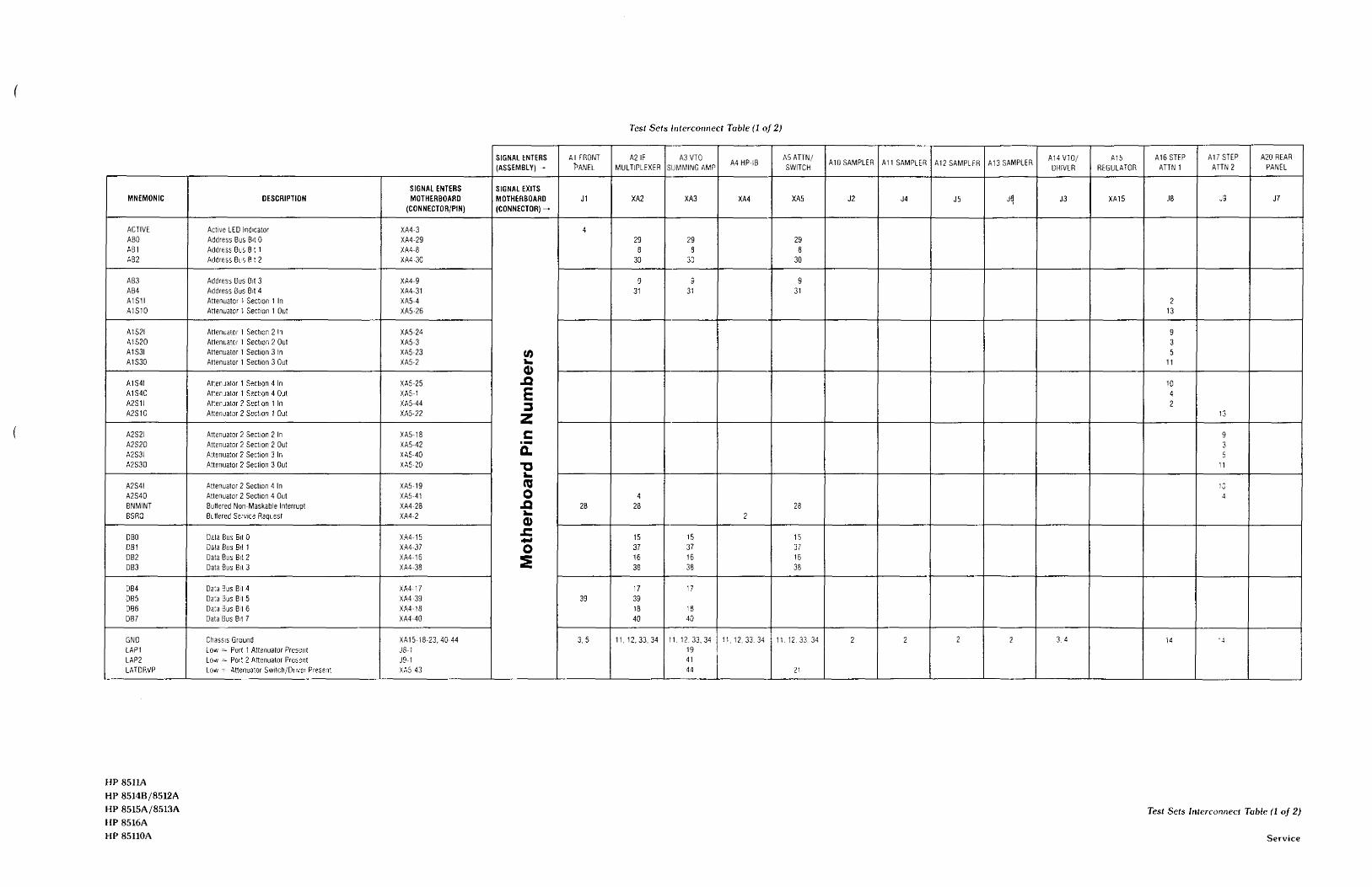

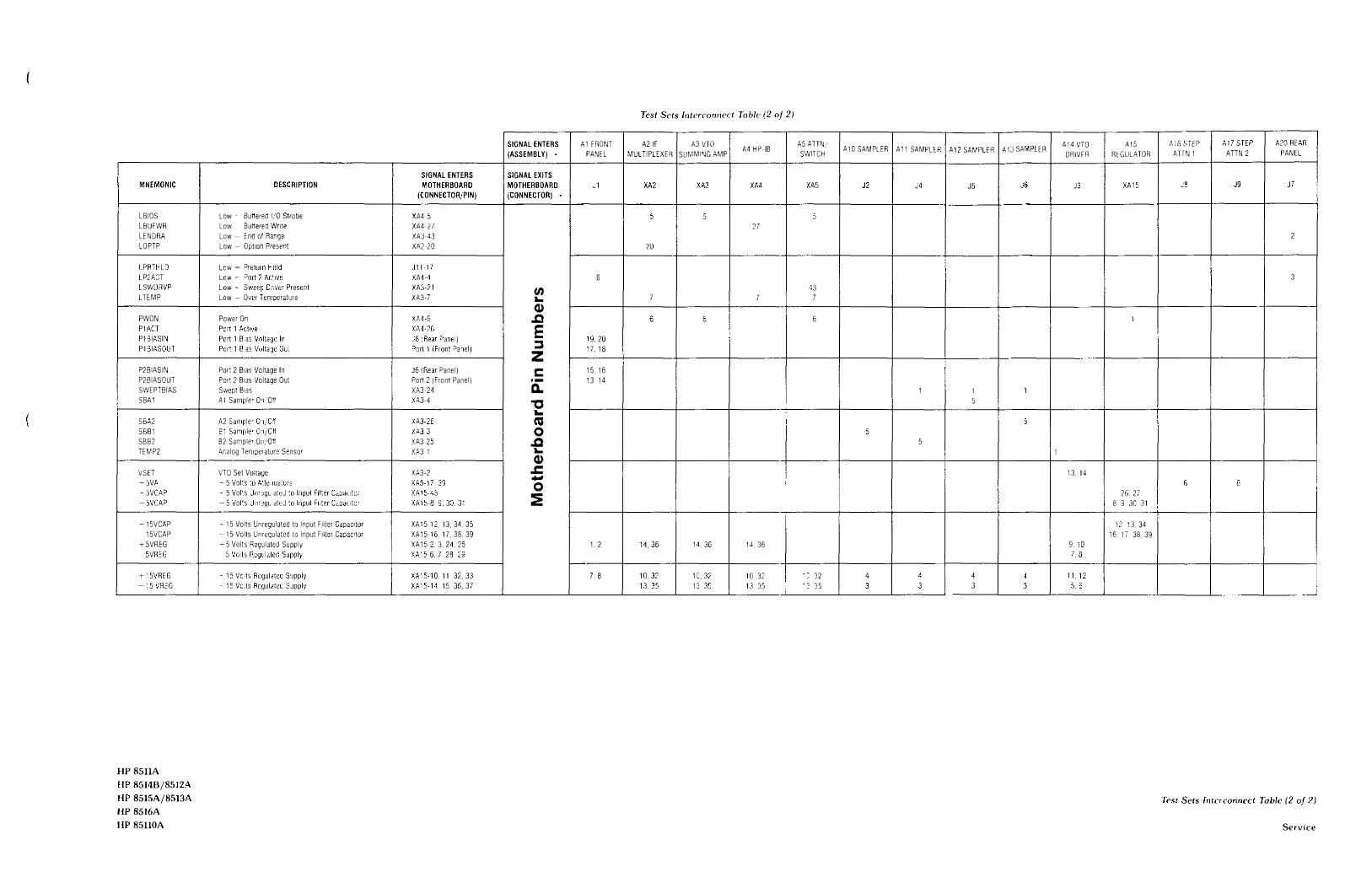


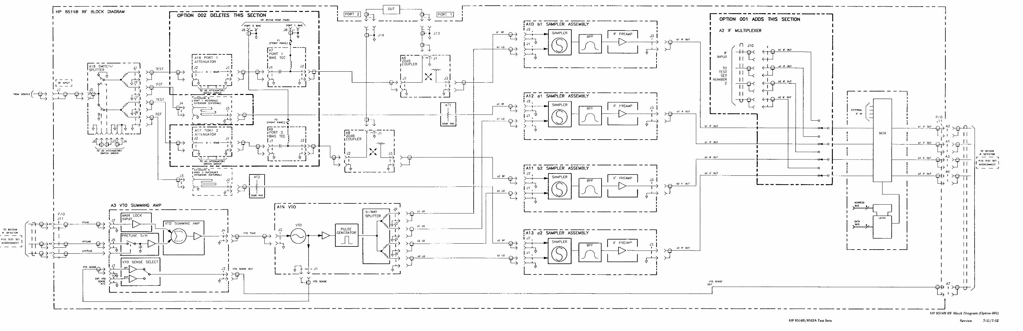


Section 8. Performance Tests
Performance test information and procedures are located in the Performance Tests section of theHP8510B System Manual and volume 2 of the HP8510A manual set. Note that the HP85108 performancetest software (supplied with the System Manual) is required to test the HP85148 up to 20 GHz.
HP 85148/8512A Test Sets Performance Tests 8-I/8-2

Section 9. Adiustments
The HP8514B and HP8512A have one adjustment only, the sampler assembly adjustment. Theprocedure is documented in the HP8510B Service Manual in the section titled Adjustments. It is also inthe Test Set Adjustments section in volume 2 of the HP 8510A manual set. The adjustment is software-guided.
This adjustment should be performed only if the need to do so is firmly established. A poor adjustmentis worse than none at all. Thus the software driven adjustment procedure begins with a check of thesampler in question to establish the need.
Do not perform the actual adjustment if the sampler passes the check.
HP 8514B/8512A Test Sets Adjustments g-119-2

Section 10. Manual Backdating
Manual backdating is not required for this manual set. This manual applies directly to instruments withthe same (or lower) serial number prefix indicated on the title page. Instruments with serial numberprefixes higher than the title page prefix may be documented in a manual update supplement.
HP 85148/8512A Test Sets Manual Backdating 10-l/10-2

REGIONAL SALES AND SUPPORT OFFICES
For information relating to Sales or Support of Hewlett-Packard products first contact your local Hewlett-Packard officelisted in the white pages of your telephone directory. If none is listed locally, contact one of the addresses listed belowto obtain the address or phone number of the Hewlett-Packard Sales or Support office nearest you.
ASIAHewlett-Packard Asia Ltd.47/F, 26 Harbour Road,Wanchai, HONG KONGG.P.O. Box 863, Hong KongTel: (852) 58330833Telex: 76793 HPA HXCable: HPASIAL TD
AUSTRALASIAHewlett-Packard Australia Ltd.31-41 Joseph StreetBLACKBURN, Victoria 3130AustraliaTel: (61) 895-2895Telex: 31-024Cable: HEWPARD Melbourne
CANADAHewlett-Packard (Canada) Ltd.6877 Goreway DriveMISSISSAUGA, Ontario L4V 1 M8Tel: (416) 678-9430Telex: 069-8644
JAPANYokogawa-Hewlett-Packard Ltd.29-21 Takaido-Higashi, 3 ChomeSuginami-ku TOKYO 168Tel: 03 (331) 6111Telex: 232-2024 YHPTOK
MEDITERRANEAN ANDMIDDLE EASTHewlett-Packard S.A.Mediterranean and Middle EastOperationsAtrina Centre32 Kifissias AvenueParadissos-Amarousion, ATHENSGreeceTel: (30) 682 88 11Telex: 21-6588 HPAT GRCable: HEWPACKSA Athens
February, 1986
BENELUX & SCANDINAVIAHewlett-Packard S.A.Uilenstede 475P.O. Box 999NL-1183 AG AMSTELVEENThe NetherlandsTel: (31) 20/43 77 71Telex: 18 919 hpner nl
SOUTH & EAST EUROPE,AFRICAHewlett-Packard S.A.7, rue du Bois-du-LanCH-1217 MEYRIN 2, GenevaSwitzerlandTel: (41) 22/83 12 12Telex: 27835 hmeaCable: HEWPACKSA Geneve
FRANCEHewlett-Packard FrancePart d’activites du Bois Briard2, avenue du Lac91040 EVRY CedexTel: 1 61077 83 83Telex: 6923 15F
GERMAN FEDERALREPUBLICHewlett-Packard GmbHHewlett-Packard-StrassePostfach 1641D-6380 BAD HOMBURGWest GermanyTel: 06172/400-OTelex: 410 844 hpbhg
ITALYHewlett-Packard ltaliana S.p.A.Via G. Di Vittorio 9l-20063 CERNUSCO SULNAVIGLIO(Milano)Tel: 02192 36 91Telex: 334632
UNITED KINGDOMHewlett-Packard Ltd.King Street LaneWinnersh, WOKINGHAMBerkshire RGll 5ARTel: 734178 47 74Telex: 847178
EASTERNUSAHewlett-Packard Co.4 Choke Cherry RoadROCKVILLE, MD 20850Tel: (301) 670-4300
MIDWESTERN USAHewlett-Packard Co.5201 Tollview DriveROLLING MEADOWS, IL 60008Tel: (312) 255-9800
SOUTHERNUSAHewlett-Packard Co.2000 South Park PlaceP.O. Box 105005ATLANTA, GA 30348Tel: (404) 955-1500
WESTERN USAHewlett-Packard Co.5161 Lankershim Blvd.P.O. Box 3919NO. HOLLYWOOD, CA 91609Tel: (818) 506-3700
OTHER INTERNATIONALAREASHewlett-Packard Co.Intercontinental Headquarters3495 Deer Creek RoadPALO ALTO, CA 94304Tel: (415) 857-l 501Telex: 034-8300Cable: HEWPACK