hp pci lan adapters
TRANSCRIPT

HP PCI LAN Adapters
Installation Guide
Support is as close as the World Wide Web!
Come see us at this URL: http://www.hp.com/go/network_city
...and follow the links that lead you to Support, Drivers, and Technol-ogy. Our Web site has everything you need in one place, around theclock, seven days a week:
Software, agent firmware, and drivers (see “When DownloadingFiles”, below)Troubleshooting informationProduct informationSupport contacts
Your HP Reseller can help, too! Be sure to talk to your reseller about the support services they offerfor your HP networking products.
Other HP Electronic Support ServicesIf you don’t have World Wide Web access, these sources providefirmware, drivers, and technical information.ftp ftp.hp.com Name: anonymousPassword: [email protected]> bin ftp> cd /pub/networking/softwareftp> get filenameftp> quit
HP Bulletin Board Service (BBS)
With your communication/terminal emulation software:In the U.S., dial 208-344-1691In other countries, contact your reseller or local HP CustomerSupport Center (see chart on other side) for the BBS telephonenumber for your country.
Follow the menu system to find and download the latest software,agent firmware, or drivers for your HP networking product.
When Downloading Files
Files are typically named to correspond to the HP product numberof the product their intended for. If the file you download has a fileextension of “.exe”, it is a compressed file. For example, the productHP J3200A may have a file j3200a.exe that is extracted by typingj3200a [Enter].
HP FIRST Fax Retrieval Service
HP FIRST is an automated fax retrieval service that is available 24hours a day, seven days a week. HP FIRST provides a variety of prod-uct and technical information.
To access HP FIRST, dial one of the following telephone numbers:In the U.S. and Canada, dial 800-333-1917 from your fax machineor touch-tone phone.In other countries, contact your reseller or local HP CustomerSupport Center (see chart below) for the HP FIRST telephonenumber for your country.To access the U.S./Canada HP FIRST system from another coun-try, dial +1 208 344 4809 from your fax machine.
Enter the number of the document you want to receive. If you’re notsure what the number is, you can request an index by following theprompts. The information will be sent to you by return fax.
(continued on next page)
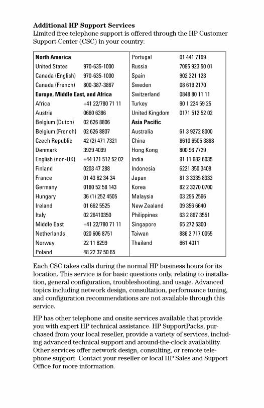
Additional HP Support Services
Limited free telephone support is offered through the HP CustomerSupport Center (CSC) in your country:
North America Portugal 01 441 7199United States 970-635-1000 Russia 7095 923 50 01Canada (English) 970-635-1000 Spain 902 321 123Canada (French) 800-387-3867 Sweden 08 619 2170Europe, Middle East, and Africa Switzerland 0848 80 11 11Africa +41 22/780 71 11 Turkey 90 1 224 59 25Austria 0660 6386 United Kingdom 0171 512 52 02Belgium (Dutch) 02 626 8806 Asia Pacific
Belgium (French) 02 626 8807 Australia 61 3 9272 8000Czech Republic 42 (2) 471 7321 China 8610 6505 3888Denmark 3929 4099 Hong Kong 800 96 7729English (non-UK) +44 171 512 52 02 India 91 11 682 6035Finland 0203 47 288 Indonesia 6221 350 3408France 01 43 62 34 34 Japan 81 3 3335 8333Germany 0180 52 58 143 Korea 82 2 3270 0700Hungary 36 (1) 252 4505 Malaysia 03 295 2566Ireland 01 662 5525 New Zealand 09 356 6640Italy 02 26410350 Philippines 63 2 867 3551Middle East +41 22/780 71 11 Singapore 65 272 5300Netherlands 020 606 8751 Taiwan 886 2 717 0055Norway 22 11 6299 Thailand 661 4011Poland 48 22 37 50 65
Each CSC takes calls during the normal HP business hours for itslocation. This service is for basic questions only, relating to installa-tion, general configuration, troubleshooting, and usage. Advancedtopics including network design, consultation, performance tuning,and configuration recommendations are not available through thisservice.
HP has other telephone and onsite services available that provideyou with expert HP technical assistance. HP SupportPacks, pur-chased from your local reseller, provide a variety of services, includ-ing advanced technical support and around-the-clock availability.Other services offer network design, consulting, or remote tele-phone support. Contact your reseller or local HP Sales and SupportOffice for more information.


Installation Guide
HP PCI LAN Adapters

©Copyright Hewlett-Packard
Company 1997. All Rights Reserved.
Reproduction, adaptation, or translationwithout prior written permission is pro-hibited, except as allowed under thecopyright laws.
Publication Number
5967-0892October 1997
Applicable Products
HP J2970A HP J2973A HP J2585BHP J2971A HP J2974A HP J3009BHP J2972A HP J2975A HP J3010B
Trademark Credits
MS-DOS® and Microsoft® are U.S.registered trademarks of MicrosoftCorporation. Ethernet is a registeredtrademark of Xerox Corporation.
Disclaimer
The information contained in this docu-ment is subject to change without notice.HEWLETT-PACKARD COMPANYMAKES NO WARRANTY OF ANY KINDWITH REGARD TO THIS MATERIAL,INCLUDING, BUT NOT LIMITED TO,THE IMPLIED WARRANTIES OF MER-CHANTABILITY AND FITNESS FOR APARTICULAR PURPOSE. Hewlett-Packard shall not be liable forerrors contained herein or for incidentalor consequential damages in connectionwith the furnishing, performance, or useof this material.Hewlett-Packard assumes no responsibil-ity for the use or reliability of its soft-ware on equipment that is not furnishedby Hewlett-Packard.
Warranty
See the warranty booklet and the regis-tration form included with the product.A copy of the specific warranty termsapplicable to your Hewlett-Packardproduct and replacement parts can beobtained from your HP Sales and Serv-ice Office or authorized dealer.
Hewlett-Packard Company8000 Foothills BoulevardRoseville, California 95747-5551916-786-8000http://www.hp.com/go/network_city
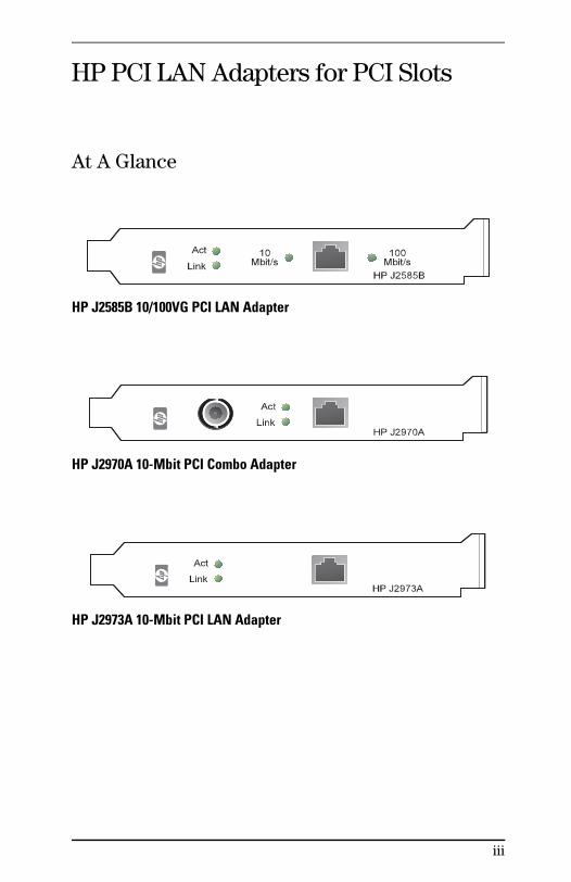
HP PCI LAN Adapters for PCI Slots
At A Glance
HP J2585B 10/100VG PCI LAN Adapter
HP J2970A 10-Mbit PCI Combo Adapter
HP J2973A 10-Mbit PCI LAN Adapter
iii
Features
For client and server computers with PCI slots(Peripheral Component Interconnect version 2.0 and later).
Fully PCI Plug-and-Play compatible; no switches or jumpers.
Compatible with IEEE 802.3 and Ethernet standards.
Compatible with IEEE 802.12 100VG standard for 100-Mbit/s(HP J2585B 10/100VG adapter only).
A single RJ-45 twisted-pair connector with automatic detectionof LAN type 10-Mbit/s or 100-Mbit/s (HP J2585B 10/100VGadapter only) when the cabling is attached.
BNC thin coaxial 10Base2 connector for 10-Mbit/s ThinLAN, analternative to the twisted-pair connector (HP J2970A Comboadapter only).
Same driver set for all HP PCI adapters for both 10-Mbit/s and100-Mbit/s operation.
Driver support for all major network operating systems.
Multiple data transfer modes supported to ensure highperformance, broad compatibility, and low CPU utilization:• Bus master mode, used by default where possible• Memory-mapped mode (also known as shared memory)• I/O-mapped mode (also known as programmed I/O or PIO)
Full-duplex capability for 10-Mbit/s operation.
LEDs for easy monitoring of LAN adapter status.
Highly integrated design for fewer components and lower failurerates.
Large on-board packet buffer memory (32 kilobytes).
Socket for boot ROM: Separate product HP J2582B Boot ROM.
Configuration and diagnostic program named HPVGSet.
Information and driver locator program named Setup, for access-ing online documentation, drivers, and HPVGSet from one point.
Capable of supporting Desktop Management Interface (DMI) andSNMP network management.
iv
Contents
Installation Guide
HP PCI LAN Adapters for PCI Slots . . . . . . . . . . . . . iiiAt A Glance . . . . . . . . . . . . . . . . . . . . . . . . . iiiFeatures . . . . . . . . . . . . . . . . . . . . . . . . . . . ivContents . . . . . . . . . . . . . . . . . . . . . . . . . . . vIncluded Parts . . . . . . . . . . . . . . . . . . . . . . . . vii100VG (IEEE 802.12) Upgrading Checklist . . . . . . . . viii
1 Installing Hardware and Software
Overview . . . . . . . . . . . . . . . . . . . . . . . . . . . . 1-2
First, install the hardware . . . . . . . . . . . . . . . . . . . 1-3Optional Full-Duplex Configuration . . . . . . . . . . . 1-5
Last, install the software and driver for operating system . 1-6A. For Microsoft Windows 95 . . . . . . . . . . . . . . . 1-7B. For Microsoft Windows for Workgroups . . . . . . . 1-10C. For Novell DOS Requestor Client (VLM) . . . . . . . 1-18D. For Novell DOS Shell Client (NETX) . . . . . . . . . 1-22
2 Troubleshooting and Getting Help
Troubleshooting Procedure . . . . . . . . . . . . . . . . . . 2-2
Basic Troubleshooting Tips . . . . . . . . . . . . . . . . . . 2-2LEDs . . . . . . . . . . . . . . . . . . . . . . . . . . . . . 2-3
Running the Diagnostics in HPVGSet . . . . . . . . . . . . 2-4General Procedure for Card Test, Link Test . . . . . . . 2-4Card Test . . . . . . . . . . . . . . . . . . . . . . . . . . 2-5Link Test . . . . . . . . . . . . . . . . . . . . . . . . . . . 2-5
Symptoms . . . . . . . . . . . . . . . . . . . . . . . . . . . . 2-8
Solutions . . . . . . . . . . . . . . . . . . . . . . . . . . . . 2-9
Customer Service and Support . . . . . . . . . . . . . . . . 2-12
v
3 Reference for HP Support Disk
Setup Reference . . . . . . . . . . . . . . . . . . . . . . . . 3-3Before Running Setup . . . . . . . . . . . . . . . . . . . 3-3Running Setup . . . . . . . . . . . . . . . . . . . . . . . . 3-3Navigation and Reading using Setup . . . . . . . . . . . 3-4Features in Setup . . . . . . . . . . . . . . . . . . . . . . 3-5
HPVGSet Reference . . . . . . . . . . . . . . . . . . . . . . 3-6Before Running HPVGSet . . . . . . . . . . . . . . . . . 3-6Running HPVGSet . . . . . . . . . . . . . . . . . . . . . . 3-7HPVGSet Primary Screen Functions . . . . . . . . . . . 3-9Manual Configuration Functions . . . . . . . . . . . . . 3-11
A Connectors and Cables
Twisted-Pair RJ-45 Connector . . . . . . . . . . . . . . . . A-210-Mbit/s Operation . . . . . . . . . . . . . . . . . . . . . A-2100-Mbit/s Operation . . . . . . . . . . . . . . . . . . . . A-3
ThinLAN BNC Connector . . . . . . . . . . . . . . . . . . . A-410-Mbit/s Operation . . . . . . . . . . . . . . . . . . . . . A-4
B Specifications . . . . . . . . . . . . . . . . . . . . B-1
C Regulatory Statements . . . . . . . . . . . . . . C-1
Index
vi

Included Parts
Either the:
• HP J2585B 10/100VG LAN Adapter,
• HP J2970A 10/100 LAN Adapter, or
• HP J2973A 10/100 LAN Adapter
One 3.5-inch HP Support Disk in a software license envelope.
The Installation Guide for the HP PCI LAN Adapters, part num-ber 5967-0892 (this manual).
Warranty booklet.
Service/support address and phone reference card.
Product Registration packet.
vii
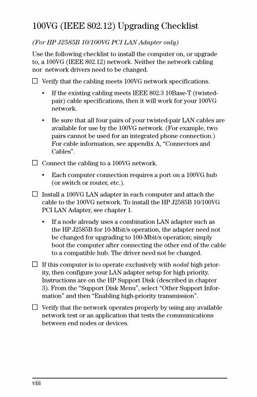
100VG (IEEE 802.12) Upgrading Checklist
(For HP J2585B 10/100VG PCI LAN Adapter only)
Use the following checklist to install the computer on, or upgradeto, a 100VG (IEEE 802.12) network. Neither the network cablingnor network drivers need to be changed.
Verify that the cabling meets 100VG network specifications.
• If the existing cabling meets IEEE 802.3 10Base-T (twisted-pair) cable specifications, then it will work for your 100VGnetwork.
• Be sure that all four pairs of your twisted-pair LAN cables areavailable for use by the 100VG network. (For example, twopairs cannot be used for an integrated phone connection.)For cable information, see appendix A, “Connectors andCables”.
Connect the cabling to a 100VG network.
• Each computer connection requires a port on a 100VG hub(or switch or router, etc.).
Install a 100VG LAN adapter in each computer and attach thecable to the 100VG network. To install the HP J2585B 10/100VGPCI LAN Adapter, see chapter 1.
• If a node already uses a combination LAN adapter such asthe HP J2585B for 10-Mbit/s operation, the adapter need notbe changed for upgrading to 100-Mbit/s operation; simplyboot the computer after connecting the other end of the cableto a compatible hub. The driver need not be changed.
If this computer is to operate exclusively with nodal high prior-ity, then configure your LAN adapter setup for high priority.Instructions are on the HP Support Disk (described in chapter3). From the “Support Disk Menu”, select “Other Support Infor-mation” and then “Enabling high-priority transmission”.
Verify that the network operates properly by using any availablenetwork test or an application that tests the communicationsbetween end nodes or devices.
viii

1
Installing Hardware and Software

Overview
To succeed, you’ll need:
The LAN adapter(in the package)
The network cabling installed
A computer with a PCI(v.2.0 or later) busexpansion slot
The appropriatesoftware driver foryour computer(in the package)
The name of your network operating system
The network operating system and the software driver use thehardware (the LAN adapter and network cabling) to communi-cate between the network and your computer.
Documentation to Assist You:
Installation Guide (this manual) containing printed instructionsfor the most common standard installations. For the other instal-lations, this manual directs you to more specific information in:
The HP Support Disk (in the package) containing online informa-tion—accessible using the Setup utility—for other installationsituations, including most operating systems and special features:• Dual- or triple-stack (multiple networks on the computer)• More than one LAN adapter in the computer• Installation in a server, rather than a client
The HP Support Disk contains:
Driver files for most network operating systems, and a list ofdrivers in “drivers.txt”.Installation and configuration documentation in ASCII text files.HPVGSet utility for special configurations and troubleshooting.Setup utility to guide you to the appropriate driver, to guide youto the documentation files, and to run HPVGSet.
Network
Installadapter
Installdriver
Computer
1-2 Installing Hardware and Software

First, install the hardware.
Note If you want to install or upgrade to MicrosoftWindows 95, do so before installing hardware.
1. Shut down the computer, exiting all running software (e.g.,Windows) first. Switch off the power and unplug the power cord.
2. Open or remove any enclosures or covers as necessary to accessthe expansion slots inside the computer, following the accessoryboard installation instructions in your computer documentation.
3. Select an open slot with a PCI connector, noting the following:• Your computer is either an EISA-and-PCI or an ISA-and-PCI
dual-bus machine.• A PCI connector is lighter in color and shorter in length than
an EISA or ISA connector.• Some slots have a PCI connector only.• Some slots have two connectors, (1) PCI and (2) EISA or
ISA. A board in the slot uses only one of the two connectors.• The adapter can occupy either a PCI-only slot or shared slot.
4. Remove the slot cover from the selected slot, and save the screw.
In case of problems:
If the slot cover is already removed, you need only the screw.
Step 3
PCI Connector(white or beige)
EISA Connector(brown or black)
ISA Connector(brown or black, 1/2 height)
√
Step 4
slot coverscrew
slot cover
Installing Hardware and Software 1-3
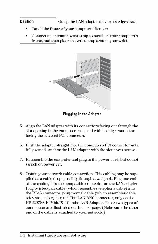
Caution Grasp the LAN adapter only by its edges and:
• Touch the frame of your computer often, or:
• Connect an antistatic wrist strap to metal on your computer’sframe, and then place the wrist strap around your wrist.
Plugging in the Adapter
5. Align the LAN adapter with its connectors facing out through theslot opening in the computer case, and with its edge connectorfacing the selected PCI connector.
6. Push the adapter straight into the computer’s PCI connector untilfully seated. Anchor the LAN adapter with the slot cover screw.
7. Reassemble the computer and plug in the power cord, but do notswitch on power yet.
8. Obtain your network cable connection. This cabling may be sup-plied as a cable drop, possibly through a wall jack. Plug one endof the cabling into the compatible connector on the LAN adapter.Plug twisted-pair cable (which resembles telephone cable) intothe RJ-45 connector; plug coaxial cable (which resembles cabletelevision cable) into the ThinLAN BNC connector, only on theHP J2970A 10-Mbit PCI Combo LAN Adapter. These two types ofconnection are illustrated on the next page. (Make sure the otherend of the cable is attached to your network.)
1-4 Installing Hardware and Software
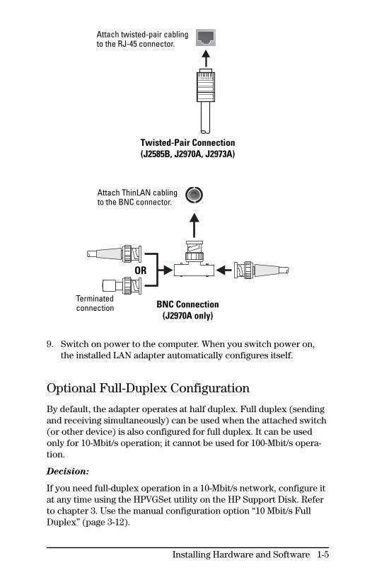
Twisted-Pair Connection(J2585B, J2970A, J2973A)
BNC Connection(J2970A only)
9. Switch on power to the computer. When you switch power on,the installed LAN adapter automatically configures itself.
Optional Full-Duplex Configuration
By default, the adapter operates at half duplex. Full duplex (sendingand receiving simultaneously) can be used when the attached switch(or other device) is also configured for full duplex. It can be usedonly for 10-Mbit/s operation; it cannot be used for 100-Mbit/s opera-tion.
Decision:
If you need full-duplex operation in a 10-Mbit/s network, configure itat any time using the HPVGSet utility on the HP Support Disk. Referto chapter 3. Use the manual configuration option “10 Mbit/s FullDuplex” (page 3-12).
Attach twisted-pair cablingto the RJ-45 connector.
Attach ThinLAN cablingto the BNC connector.
OR
Terminatedconnection
Installing Hardware and Software 1-5
Last, install the software and driver foryour operating system
Your software instructions depend on the operating system. Thefollowing decision gives you the location of your instructions. Yourspecific instructions are the only section you will use in theremainder of this chapter.
Decision:
What is the operating system for this computer?
Microsoft:
• Windows 95: Follow only section A on pages 1-7 to 1-9.
• Windows for Workgroups: Follow only section B on pages1-10 to 1-17.
• Windows 3.x: Along with Windows, you have either “Novell”or “Other” for networking; see that bullet below.
• DOS: Along with DOS, you have either “Windows for Work-groups” or “Novell” or “Other” for networking; see that bulletbelow.
Novell:
• DOS Requestor (VLM), for DOS on this client computer,with or without Microsoft Windows 3.x:Follow only section C on pages 1-18 to 1-21.
• DOS Shell (NETX), for DOS on this client computer,with or without Microsoft Windows 3.x:Follow only section D on pages 1-22 to 1-26.
• Novell NetWare on this computer as a server:If installing the LAN adapter on a server, see “Other” below.
Other network operating system:Skip the rest of this chapter and go to the online instructions onthe HP Support Disk (included in your product package). Referto chapter 3 for assistance in using the Setup utility. FromSetup’s “Support Disk Menu”, select “Instructions for installing”and then select your network service vendor.
1-6 Installing Hardware and Software

A. For Microsoft Windows 95
In addition to the LAN adapter driver, this procedure automaticallyprovides both of the following types of networking software:
Client for Microsoft Networks, for using resources shared oncomputers with Microsoft NOSsClient for NetWare Networks (with IPX/SPX-compatibleprotocol), for connecting to NetWare servers
Prerequisite: Before doing this procedure, Windows 95must have been installed before the adapterhardware was installed and cabled.
In case of problems:
• If Windows 95 has not yet been installed or upgraded and theadapter hardware is already installed, then remove theadapter and then install or upgrade Windows 95, before doingthe procedure in this section A.
• If the adapter hardware was installed and then Windows 95was installed and upgraded, then your installation probablywill not operate correctly. Stop this procedure and go to theinstructions on the HP Support Disk. Refer to chapter 3 forassistance in using the Setup utility. From Setup’s “SupportDisk Menu”, select “Other Support Information” and then“Windows 95 troubleshooting”.
Task 1. Install Microsoft Windows 95 driver for the adapter.
1. Windows 95 automatically detects the LAN adapter just installedand displays the “New Hardware Found” dialog box.
In case of problems:
If the “New Hardware Found” dialog box does not display,stop this procedure and go to the procedure “Recoveringfrom Missing New Hardware Found Dialog Box” on page 1-9.
2. Select “Driver from disk provided by hardware manufacturer”[OK]. The “Install From Disk” dialog box appears.
3. Insert the HP Support Disk into the floppy drive, for example,drive “a” and enter the path:
a:\
Installing Hardware and Software 1-7
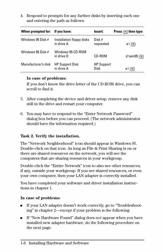
4. Respond to prompts for any further disks by inserting each oneand entering the path as follows:
When prompted for: If you have: Insert: Press [OK] then type:
Windows 95 Disk # Installation floppy disksin drive A
Disk #requested a:\ [OK]
Windows 95 Disk # Windows 95 CD-ROMin drive D CD-ROM d:\win95 [OK]
Manufacturer’s disk HP Support Diskin drive A
HP SupportDisk a:\ [OK]
In case of problems:
If you don’t know the drive letter of the CD-ROM drive, you canscroll to find it.
5. After completing the device and driver setup, remove any diskstill in the drive and restart your computer.
6. You may have to respond to the “Enter Network Password”dialog box before you can proceed. (The network administratorshould have the information required.)
Task 2. Verify the installation.
The “Network Neighborhood” icon should appear in Windows 95.Double-click on that icon. As long as File & Print Sharing is on orthere are shared resources on the network, you will see thecomputers that are sharing resources in your workgroup.
Double-click the “Entire Network” icon to also see other resources,if any, outside your workgroup. If you see shared resources, or evenyour own computer, then your LAN adapter is correctly installed.
You have completed your software and driver installation instruc-tions in chapter 1.
In case of problems:
If your LAN adapter doesn’t work correctly, go to “Troubleshoot-ing” in chapter 2—except if your problem is the following:
If “New Hardware Found” dialog does not appear when you haveinstalled new adapter hardware, do the following procedure onthe next page.
1-8 Installing Hardware and Software
Recovering from Missing “New Hardware Found” Dialog Box
Note Possible Causes:
• Ignoring the first instance of the “New Hardware Found”dialog box when restarting the computer after installingadapter hardware. This happens when you select theresponse “Do not install a driver (Windows will not promptyou again)”.
• Upgrading to Windows 95 after installing adapter hardware.
1. From the Control Panel, run the “Add New Hardware” Wizard.
2. Click [Next >]. Select “Yes” for detection and click [Next >].
3. Click [Next >] and wait for the device to be found. Then click [Next >]for manual installation.
4. For “Hardware types”, click “Network adapters” and [Next >].
5. In the “Select Device” dialog box, click [Have Disk], and the “InstallFrom Disk” dialog box appears.
6. Insert the HP Support Disk into the floppy drive. Enter the path:a:\
7. In the “Select Device” dialog box, click the product name of thespecific LAN adapter you have installed [OK]. Click [Next >].
8. Click [Finish]. Close the Control Panel.
9. Remove the support disk from the floppy drive and restart yourcomputer.
10. Test the LAN adapter according to the procedure “Task 2. Verifythe installation” on page 1-8.
In case of problems:
Go to “Troubleshooting” in chapter 2.
Installing Hardware and Software 1-9
B. For Microsoft Windows for Workgroups
Task 1. Record the configured base I/O address.
When you switch on power to your computer after installing theadapter, the adapter is automatically configured. For a Windows ForWorkgroups installation, you need to record some information fromthat configuration.
1. Boot your computer in DOS without loading network software,network drivers, or any memory manager. Decide among thealternative methods listed below.
Note This procedure will not work in a DOSwindow within a Windows environment.
Decision:
• If you run MS-DOS version 6.0 or later (check by using theDOS command “ver”), then boot and press the [F5] key whenyou see the text “Starting MS-DOS....” You should then see“MS-DOS is bypassing your CONFIG.SYS and AUTOEXEC.BATfiles”.
• Or, boot from a DOS boot diskette, without “config.sys” or“autoexec.bat” file on it. See the DOS documentation for help.
• Or, if you understand how your network software, networkdrivers, and memory manager are activated, then temporar-
ily modify the “config.sys” and “autoexec.bat” files so thatthose items do not execute.
2. Insert the HP Support Disk into the floppy drive, for example,drive “a”, and change to that drive if necessary. Run the utility“Setup” on that disk.
a:setup
1-10 Installing Hardware and Software
3. From the “Support Disk Menu”, select “View, configure, or testLAN Adapter card”. The configuration of the LAN adapter isdisplayed in the “Selected Card Status” area.
In case of problems:
• If more than one HP adapter is installed, then use “SelectcarD” to select the specific adapter you are installing.
• If the utility fails to find your LAN adapter, follow the instruc-tions displayed. Recheck all hardware and software installa-tion procedures, especially the following possibilities:
– Check that the adapter is plugged into a PCI connector,which is usually white and shorter than an ISA or EISAconnector.
– With the computer’s power switched off, reseat theadapter, pushing it straight into the slot.
– Check that the PCI slot used is enabled, if the computer’smotherboard allows disabling and enabling PCI slots.Check the computer documentation for this possibility.
For further diagnosis see “Troubleshooting”, chapter 2.
4. In the “Selected Card Status” area, the second column is the “I/OAddress Range” configured for the adapter. The range is shownas two hexadecimal numbers with a dash between and “H” after.Write down the 4 characters displayed before the dash (e.g., if“D000-D0FFH” appears, write down “D000”). You will use thisbase address in step 7 below on page 1-14.
5. Select “Exit Program” in HPVGSet’s Main Menu.Select “Exit SETUP” from Setup’s Support Disk Menu.Remove the support disk.
Installing Hardware and Software 1-11

Task 2. Install the network software.
Decision:
If Microsoft Windows For Workgroups is not yet installed, thendo “Task 2 Alternative A” immediately below.
If Microsoft Windows For Workgroups is already installed, thenskip to “Task 2 Alternative B” on page 1-13. Do not do “Alterna-tive A” immediately below.
Task 2, Alternative A. Install Windows For Workgroups and
select the network.
Install Microsoft Windows For Workgroups 3.11. Refer to the operat-ing system’s documentation, for example, “Getting Started” manual.
1. In DOS, insert the Microsoft disk labeled “Disk 1—Setup” intothe floppy drive, for example, drive “a”, and execute “setup”, asfollows:
a:
setup
Follow the instructions on each window.
2. When you see the dialog box “Network Setup”, displaying“No Network Installed”, click [Networks] button.
3. In the dialog box “Networks”, choose one of the following:
Decision:
• If you want the Microsoft Windows Network, click on the ra-dio button “Install Microsoft Windows Network” and thenclick [OK].
• If you want a network other than the Microsoft Windows Net-work, click on the radio button “Install Windows support forthe following network only”, select the network from the list,and then click [OK].
4. The dialog box “Network Setup” appears. Go on to task 3 onpage 1-14 for driver installation (skip “Task 2 Alternative B”).
1-12 Installing Hardware and Software

Task 2, Alternative B. If Windows For Workgroups is already
installed, select the network.
Note Alternative A is on the previous page.
1. Start Windows.
2. Double-click on the Network group. The Network group windowopens.
3. Double-click on the Network Setup icon. The applicationlaunches and displays the dialog box “Network Setup”.
4. Click the “Networks” button. The dialog box “Networks”appears. Choose one of the following:
Decision:
• If the radio button for “No Windows support for Networks” isselected (which means the network software is not yet setup) and you want the Microsoft Windows Network:
Then click on the radio button “Install Microsoft WindowsNetwork” and then click [OK].
• If the radio button for “No Windows support for Networks” isselected (which means the network software is not yet setup) and you want a network other than the Microsoft Win-dows Network:
Then click on the radio button “Install Windows supportfor the following network only”, select the network fromthe list, and then click [OK].
• If the network you want has already been set up, click [Cancel].
5. The dialog box “Network Setup” appears. Go on to task 3 on thenext page for driver installation.
Installing Hardware and Software 1-13
Task 3. Install the Windows For Workgroups 3.11 driver for
the LAN adapter.
1. In the dialog box “Network Setup”, click [Drivers...]. The dialog box“Network Drivers” appears.
2. In the dialog box “Network Drivers”, click [Add Adapter]. The dialogbox “Add Network Adapter” appears.
3. In the dialog box “Add Network Adapter”, highlight and selectthe line “Unlisted or Updated Network Adapter”.
4. When the “Install Driver” dialog box appears, insert the HP Sup-port Disk into the floppy drive, “a” for example, and enter:
a:\wfwg
5. Then the dialog box “Unlisted or Updated Network Adapter”appears, containing the product number and name of your LANadapter, for example:
HP J2585B 10/100VG PCI LAN Adapter
In case of problems:
If the adapter number and name do not appear, refer to theHP Support Disk for help in diagnosing and resolving thissituation. Run the Setup utility. Refer to chapter 3. Select“Instructions for installing”, “Microsoft”, and “Windows forWorkgroups”. See the “Note on OEM Information Files”section at the end of the file.
6. In the dialog box “Unlisted or Updated Network Adapter”, high-light and select the adapter number and name. A dialog boxtitled with that product number and name is displayed.
7. In that LAN adapter dialog box, you are prompted for the “BaseI/O Port”—the address you recorded from the HPVGSet “Se-lected Card Status” display in task 1, step 4, above on page 1-11.Enter the first 4 characters of the address range you saw there.
(You can omit the “0x” in front of the 4-character number—such as “0xD000”—or you can leave it there. It indicates ahexadecimal number, just as the “H” at the end of the addressrange in HPVGSet—such as “D000-D0FFH”—indicates hexa-decimal numbers.)
Click [OK]. The dialog box “Network Drivers” appears.
1-14 Installing Hardware and Software

8. In the dialog box “Network Drivers”, click [Close]. The dialog box“Network Setup” appears. Click [Continue] button.
9. If the dialog box “Microsoft Windows Network Names” appears,enter the names appropriate for your computer and network(which the network administrator should know), and click [OK].Otherwise, go on to the next step.
10. You will be prompted to insert either or both of the followingdisks, any number of times in any order. Whenever you insert therequested disk, make sure the appropriate path name is enteredas follows.
• After inserting any Windows For Workgroups disk, make surethe path is the root of the floppy drive, for example:
a:\
• After inserting the HP Support Disk, in drive “a” for example,enter the path:
a:\wfwg
11. After the requested disks have been read, the “Network Setup”dialog box says that the “config.sys”, “autoexec.bat”, “proto-col.ini”, and “system.ini” files have been modified.Remove the last disk from the floppy drive and click [OK].The driver is installed into the Windows For Workgroupsenvironment.
In case of problems:
If instead of the above result, you are notified of MS-DOS Mul-tiple Configuration Menus in the “config.sys” file, then youmust make your own modifications to some of those files.You are notified of the locations of sample files. Note them,click [OK], and continue until you return to DOS. Then checkthe sample files and make the modifications you want. Themodifications critical to networking include:
DEVICE=C:\WINDOWSDIRECTORY\IFSHLP.SYSin “config.sys”
C:\WINDOWSDIRECTORY\NET START
in “autoexec.bat”PATH=C:\WINDOWSDIRECTORY; in “autoexec.bat”
Installing Hardware and Software 1-15
12. The dialog box “Windows Setup” says you must restart yourcomputer.
Decision:
• If Windows For Workgroups has already been fully installed(that is, you did task 2, alternative B, on page 1-13), click[Restart Computer].
• If you were just installing Windows For Workgroups by doingtask 2, alternative A, on page 1-12, click [Continue] now. Thenproceed with the Windows for Workgroup Setup programuntil the setup procedure is completed.
Click [OK] or [Close] to complete any changes in the “NetworkSettings” or LAN adapter dialog box.
The installation and/or changes of network configuration willnot take effect until the computer is booted.
13. The first time you start Windows For Workgroups after the instal-lation, the dialog box “Welcome to Windows For Workgroups”should request a password.
Decision:
• If you do not want password protection, click [OK]. At thesecond chance to create a password file, click [No].
• If you want password protection, enter a password and click[OK].
In case of problems:
If you are not requested to supply a password, the networkprobably is not installed correctly. Refer to “Troubleshooting”in chapter 2.
1-16 Installing Hardware and Software

Task 4. Verify the installation.
Wait a few minutes and perform a network operation. Examples:
Start File Manager. Select “Connect Network Drive...” from theDisk menu. If there are shared resources on the network, the“Connect Network Drive” dialog box should display them. Theremay be some delay before this happens. Failure will usually bereported in less than 5 minutes; no response after 5 minutesusually means that you will eventually get a response.
Click on the “MS-DOS Prompt” icon to open a DOS window.Enter the following DOS commands:
net config
(Note your computer name in the response.)net view \\COMPUTERNAME
(Supply the computer name.)
If you see no error messages, installation is verified. You havecompleted your software and driver installation instructions inchapter 1.
In case of problems:
If the network does not work correctly, go to “Troubleshooting” inchapter 2.
Installing Hardware and Software 1-17
C. For Novell DOS Requestor Client (VLM)
This procedure installs the 16-bit Open Data-Link Interface (ODI)driver that allows the DOS Requestor (VLM) to access the LAN andthe Novell servers.
Decisions:
There are two ways a client computer with DOS and/or Windows3.x can use a Novell network: VLM (DOS Requestor) or NETX(DOS Shell). The network administrator should determinewhether to use the new, faster VLM or the older NETX. If you arenot sure which one to use, and you are installing Novell NetWareusing the standard procedure, then use VLM.If you need the NETX procedure instead of this VLM procedure,go to section D on page 1-22 instead.
If you will be using product J2585B 10/100VG PCI LAN Adapterin a 100VG network (rather than in a 10-Mbit/s network), thenHP recommends that you install VLM version 1.20B or later inthe following procedure. If your version is too early, copy a laterversion from a Novell server; see page 1-23 for sources.
If you are using a “dual stack”—Microsoft Windows forWorkgroups along with Novell—then use the “Instructions forinstalling” in the Setup utility on the HP Support Disk instead(described in chapter 3). Select “Microsoft” and then “Windowsfor Workgroups 3.11 client”.
Task 1. Install DOS if not already installed on this computer.
Task 2. Install Microsoft Windows 3.x if needed and not
already installed.
1-18 Installing Hardware and Software

Task 3. Install the Novell DOS Requestor software and the
driver for the LAN adapter.
1. Find the Novell installation diskettes for “Novell Client for DOSand MS Windows” (probably labeled “WSDOS_1” or “WSWIN_1”).
Note If you do not have these diskettes, follow theinstructions in the Novell documentation tocreate the NetWare client installation disk-ettes from the NetWare CD-ROM.
2. In DOS, insert the first Novell installation diskette into the floppydrive and start the Install utility. For example:
a:install
3. Follow Novell’s installation instructions on the screen to fill inthe fields, selecting the following specifics:
4. To allow the Novell installation program to modify the“autoexec.bat” and “config.sys” files, answer “Yes”. The result isthat every time you boot your computer, the NetWare client willstart automatically and attach to the server.
5. To add Windows support, if Windows 3.x is installed, answer“Yes”.
6. When asked to select the network board driver, press [Enter]. Inthe ”Network Board” window, highlight the selection “OTHERDRIVERS” at the end of the list displayed and press [Enter].
7. When the “Insert the Driver Disk” window is displayed, removethe Novell diskette and insert the HP Support Disk into thefloppy drive and press [Enter].
8. The “Network Board” window appears. Highlight the Hewlett-Packard selection containing the words “Bus Master”.
9. Press [Enter], and the driver “hpfeodim.com” will be installed fromthe support disk to your computer.
Installing Hardware and Software 1-19

10. The Novell Install Utility then offers you a chance to override thesettings for the LAN adapter.
Decision:
• If you are installing more than one HP LAN adapter in thisclient computer, you will use some optional overrides at thispoint. Refer to the “Instructions for installing” in the Setuputility on the HP Support Disk (described in chapter 3).Select “Novell” and then “DOS Requestor client (VLM)”. Seethe end of the file. Then go on to step 11.
11. Continue with the Novell Install Utility. When notified that it isfinished, remove the HP Support Disk from the floppy drive.
Your Novell network installation procedure is complete (youneed not load any further networking software).
The configuration file changes will take effect when you rebootyour computer; go on to task 4 for testing.
Task 4. Verify the installation.
Reboot the computer and look for the notification that you areattached to a server. This verifies that you have successfully com-pleted your software and driver installation instructions in chapter 1.
In case of problems:
If notified to update “lsl.com” or “ipxodi.com” or both, copy thelatest versions of the file(s) from a Novell server; see page 1-23.Then repeat task 4.
If you cannot attach to the server, then check the versions offiles “ipxodi.com” and “lsl.com” after you boot in native DOSwithout loading networking or memory managers, as follows:
a. Switch off power. Then switch on power and boot cleanly:
Decision:
– In MS-DOS version 6.0 or later (check by using the DOScommand “ver”), boot and press the [F5] key when you seethe text “Starting MS-DOS....” You should then see “MS-DOSis bypassing your CONFIG.SYS and AUTOEXEC.BAT files”.
– Or, boot from a DOS boot diskette, without “config.sys” or“autoexec.bat” files on it. See the DOS documentation.
1-20 Installing Hardware and Software
b. Connect to the NetWare directory, probably “nwclient”.
c. At the DOS prompt, execute “ipxodi”. Then execute “lsl”.
d. Check the version numbers: ipxodi 2.20 or laterlsl 2.11 or later
If versions are too early, copy the latest versions of “lsl.com”and/or “ipxodi.com” from a Novell server; see page 1-23. Thenrepeat task 4. If versions are correct, there is another prob-lem.
If the LAN adapter does not work correctly, go to “Troubleshoot-ing”, chapter 2.
Installing Hardware and Software 1-21

D. For Novell DOS Shell Client (NETX)
This procedure installs the 16-bit Open Data-Link Interface (ODI)driver that allows the DOS Shell (NETX) to access the LAN and theNovell servers.
Decisions:
There are two ways a client computer with DOS and/or Windows3.x can use a Novell network: VLM (DOS Requestor) or NETX(DOS Shell). The network administrator should determinewhether to use the new, faster VLM or the older NETX. If you arenot sure which to use, and you are installing Novell NetWareusing the standard procedure, then use VLM.If you need the VLM procedure instead of this NETX procedure,go to section C on page 1-18 instead.
If you are using a “dual stack”—Microsoft Windows for Work-groups along with Novell—then use the “Instructions for install-ing” in the Setup utility on the HP Support Disk instead. Select“Microsoft” and then “Windows for Workgroups 3.11 client”.
If you are doing none of the above, then proceed with the tasks:
Task 1. Find supported versions of the Novell DOS Shell
client installation files.
The files required for all installations and their supported versions:lsl.com v. 2.11 or lateripxodi.com v. 2.20 or laternetx.exe or
netx.com any version and date
There may be additional NetWare client Windows files required for anew client software installation on a computer with Windows 3.x.
1-22 Installing Hardware and Software

To check the version numbers of the files wherever they are stored,execute the files on a computer booted in native DOS without load-ing networking or memory managers, as follows:
a. Switch off power. Then switch on power and boot cleanly:
Decision:
– In MS-DOS version 6.0 or later (check by using the DOScommand “ver”), boot and press the [F5] key when you seethe text “Starting MS-DOS....” You should then see “MS-DOSis bypassing your CONFIG.SYS and AUTOEXEC.BAT files”.
– Or, boot from a DOS boot diskette, without “config.sys” or“autoexec.bat” files on it. See the DOS documentation.
b. Connect to the directory containing the files, for example,“a:\nwclient” on a floppy diskette.
c. At the DOS prompt, execute “ipxodi”.Check that the version number is 2.20 or later.
d. At the DOS prompt, execute “lsl”.Check that the version number is 2.11 or later.
Sources of up-to-date required files:
Novell DOS Shell client installation diskette—the diskette youhave used to install Novell software on the other computers inyour network—possibly in the root or “dosodi” directory.
Novell NetWare CD-ROM, performing Novell’s instructions tocreate the NetWare client diskettes from the NetWare CD-ROM
You can update these files with the latest supported version, orget the files in the first place, by downloading from The NovellNetWire using a fully networked PC. Methods of access include:
• The Internet (or a modem): ftp.novell.com• CompuServe, in the area: NOVFILES• World Wide Web URL: http://www.netwire.novell.com
Task 2. Install DOS if not already installed on this computer.
Task 3. Install Microsoft Windows 3.x if needed and not
already installed.
Installing Hardware and Software 1-23
Task 4. Install Novell client files and the LAN adapter driver.
1. Create a directory on the DOS boot drive for the Novell and HPfiles, as in the following example at the DOS prompt:
mkdir c:\novell
2. Copy the Novell client files from their storage media to the direc-tory created in step 1. The required files, supported versions, andsources are described under “Task 1” on page 1-22. For example:
copy a:\lsl.com c:\novellcopy a:\ipxodi.com c:\novell
copy a:\netx.exe c:\novell
3. Insert the HP Support Disk into the floppy drive and copy thedriver file “hpfeodim.com” from the disk’s “dos” directory to thedirectory created in step 1 above, as follows:
copy a:\dos\hpfeodim.com c:\novell
4. Copy the “net.cfg” file from the “dos” directory on the HPSupport Disk to the directory created in step 1 above.
copy a:\dos\net.cfg c:\novell
Note Then the “net.cfg” file contains the followingtext. It also contains text for an additionaldriver. Only the section related to the driveryou installed will be used.
; Bus-master DOS ODI driver
LINK DRIVER HPFEODIM FRAME ETHERNET_802.3
5. In the “net.cfg” file, verify the Ethernet frame type(s) to be recog-nized by your station. The network administrator should knowthis. Edit or add to the “FRAME” line if necessary. The lineincluded in the HP-supplied file listed above causes 802.3 frametype to be recognized. Any number of the following lines may beused. They must be indented at least 2 spaces. FRAME ETHERNET_802.2 FRAME ETHERNET_802.3
FRAME ETHERNET_II
FRAME ETHERNET_SNAP
Frame type 802.2 is defaulted if no “FRAME” line is used.
1-24 Installing Hardware and Software
6. Add more parameters to your “net.cfg” file if necessary:
Decision:
If you are installing more than one HP LAN adapter in this clientcomputer, go to the “Instructions for installing” in the Setuputility on the HP Support Disk; select “Novell” and then “DOSrequestor client (NETX)”. Follow the instructions in the“NET.CFG Parameters” section. Then continue this procedure.
7. Use the “type” command to verify all the changes to “net.cfg”.
8. Edit your computer’s “autoexec.bat” file to start the Novell Net-Ware client and load the driver automatically when booting thecomputer, as shown below. Also delete any existing driver namethat was used with a LAN adapter that you have replaced. Alter-natively, you can execute the commands shown—in DOS—anytime that you wish to start networking. (This example assumesthat “c:\novell” is the directory made in step 1.)
c:
cd \novelllsl.com
hpfeodim.comipxodi.com
netx.exe or netx.com (See task 1)
Use the “type” command to verify all the changes to the“autoexec.bat” file.
9. The use of the file “netx.exe” or “netx.com” requires that youedit your computer’s “config.sys” file to include the “lastdrive=”statement. Set it to the last letter to be used by your local drives.The next letter will be the first available for Novell networkdrives. For example:
lastdrive=D
Use the “type” command to verify the change to the “config.sys”file.
10. Remove the HP Support Disk from the floppy drive.Reboot your computer to have the file changes take effect.Go on to task 6 on the next page, for testing.
Installing Hardware and Software 1-25

Task 6. Verify the installation.
Reboot the computer and look for the notification that you areattached to a server. This verifies that you have successfully com-pleted your software and driver installation instructions in chapter 1.
In case of problems:
If your LAN adapter does not work correctly, go to “Troubleshoot-ing”, chapter 2.
1-26 Installing Hardware and Software

2
Troubleshootingand Getting Help
Troubleshooting Procedure
To resolve any problems with the LAN adapter:
1. Gather some symptomatic data first:
a. First, check the basic items listed under “Basic Troubleshoot-ing Tips” beginning on the next page.
b. Then if necessary, run the diagnostic tests of the LAN adapterand the network that are available in the HPVGSet utility. See“Running the Diagnostics” on page 2-4.
2. Then compare the data you collect from these observations anddiagnostic tests with the symptoms table (on page 2-8). Once youfind the matching symptom, go to the solutions table (on page2-9) to find how to resolve the problem.
3. If you cannot resolve the problem as described in the previoussteps, refer now to the “Customer Service and Support” sectionon page 2-12.
Basic Troubleshooting Tips
Check the network cables.
Make sure the network cable connections are secure and thatthe cables are not damaged. If you find any connections that areloose or cables that are damaged, fix them and then see if yourcomputer can communicate on the network.
Check the LEDs.
The LEDs on the adapter—as seen on the illustrations on thenext page—help identify problems.
2-2 Troubleshooting and Getting Help

LEDs
Act (activity) is lit when data is being transmitted or received.
Link is lit during normal operation. Possible causes if it is not lit:
Cable not connected to the adapter.Cable not connected to a live network.Defective cable.Defective LAN adapter.ThinLAN is being used (J2970A only). This is normal operation.
HP J2585B 10/100VG PCI LAN Adapter
HP J2970A 10-Mbit PCI Combo Adapter
HP J2973A 10-Mbit PCI LAN Adapter
100-Mbit/s (J2585B only) is continuously lit during 100VGoperation (and 10-Mbit/s is not lit).
10-Mbit/s (J2585B only) is continuously lit during 10-Mbit/sEthernet or 10Base-T operation (and 100-Mbit/s is not lit).
Both 100-Mbit/s and 10-Mbit/s (J2585B only) flash alternatelyfor the following possible causes:
Cable not connected to the adapter.Cable not connected to a live network.Defective cable.
Troubleshooting and Getting Help 2-3
Running the Diagnostics in HPVGSet
General Procedure for Card Test, Link Test
1. Exit to or boot your computer in native DOS with network soft-ware and drivers not loaded. Depending on your environment:
• If you run Microsoft Windows NT, OS/2, Novell NetWare on aserver, or Unix: Select the shutdown procedure and boot toDOS. Then perform alternative a, c, or d below.– If DOS is not installed, then perform alternative c below.
• If you run Microsoft Windows 95: Perform alternative b, c, ord below.
• If you run Microsoft Windows for Workgroups or MicrosoftWindows 3.x: Select the shutdown procedure or exit to DOS.Then perform alternative a, c, or d below.
• If you run DOS only: Perform alternative a, c, or d below.
Select one of the appropriate clean boot alternatives:
a. If you run MS-DOS version 6.0 or later (use the DOS command“ver” to check), then boot and press the [F5] key when you seethe text “Starting MS-DOS....” You should then see “MS-DOS isbypassing your CONFIG.SYS and AUTOEXEC.BAT files”.
b. In Windows 95, shut down your computer. Cycle power. Pressthe [F8] key when you see the text “Starting Windows 95” atthe upper left of a blank screen. You should then see the“Microsoft Windows 95 Startup Menu”. Select option 7,“Safe mode command prompt only”.
c. Boot from a DOS boot diskette, without “config.sys” or“autoexec.bat” files on it. See DOS documentation for help.
d. If you understand how your network, drivers, and memorymanager are activated, then temporarily modify the “auto-exec.bat” and “config.sys” files so that they do not execute.
2. Execute HPVGSet on the HP Support Disk in the floppy diskdrive. In DOS, change to the floppy drive and do either: • Enter “setup”. Select the menu item “View, Configure, or Test
LAN Adapter Card”.• Or simply enter “hpvgset”.
2-4 Troubleshooting and Getting Help

3. From the Main Menu, select “Card test” (hot key [C]) or “Link test(hot key [L]). Each test is described on the following pages.
Card Test
This tests the LAN adapter’s circuitry through to the LAN connec-tors. Do not attach cables for this test. HP recommends that you runthe card test any time you change the configuration.
Upon selecting the card test, the list of tests is displayed, followedby a pass or fail indication as each test is completed.
Card Test Results
If the memory-mapped address range has been configured aboveextended memory, the card test procedure attempts to temporar-ily move that address range to an empty block of the upper mem-ory area to complete testing. Continue by pressing a key.
If a test fails, the process stops. If that is the bus master test, seethe next item. Otherwise, press the [F1] (help) key for instructions.
If the bus master test fails, this means that the PCI slot is notenabled for bus mastering. Do one of the following:• Enable bus mastering on that PCI slot. See your computer’s
documentation.• Move the adapter to another slot enabled for bus mastering.
See your computer’s documentation.• If you do not have or cannot enable any bus master expan-
sion slots, then install a driver for I/O-mapped or memory-mapped mode (an “IOMEM” driver). Instructions are on theHP Support Disk. Refer to chapter 3 for how to use Setup.From Setup’s “Support Disk Menu”, select “Instructions forinstalling” and then select your network service vendor.IOMEM instructions are in the file for your specific NOS.
Link Test
This tests the LAN adapter’s ability to send and receive packets. Thenetwork cable must be attached to the LAN adapter. The test sendsIEEE 802.2 test packets out on the network.
A link test requires two nodes, an initiator to send and a responderto answer. A “smart” hub or managed network device is usuallyconfigured to respond to IEEE 802.2 test packets with test response
Troubleshooting and Getting Help 2-5
packets. For most servers and other clients, the two devices must bespecifically set in responder and initiator modes at the same time.
When you select the link test, you are prompted to select the role,either initiator or responder, for the local node.
If the two nodes have HP LAN adapters installed, have HPVGSet run-ning link test on both nodes at the same time. Place the responder inresponder mode and then place the initiator in initiator mode andstart the test. After the test completes, exit the responder mode onthe other node. The procedure is detailed below.
Procedure for Link Test Responder
This procedure for setting up a responder is not needed if a node onthe network is always configured to respond to IEEE 802.2 testpackets. Such a node might be a managed (“smart”) hub or switch orrouter. In this case, skip to “Procedure for Link Test Initiator” below.
If the node to be set up in responder mode does not have an HP LANadapter, see its documentation for how to set it up as a responder toIEEE 802.2 test packets, instead of using this procedure. If it does
have an HP LAN adapter, then use this procedure on that node.
1. First perform the general procedure on page 2-4, and read aboutlink test initiators and responders starting on page 2-5.
2. After selecting “Link test” and when prompted for the role of thisLAN adapter, select “Respond to test packets”. This LAN adapteris then ready to return an IEEE 802.2 response packet for eachtest packet it receives from an initiator. Perform the “Procedurefor Link Test Initiator” below, and when complete, return to thisprocedure.
3. HPVGSet displays a test window showing counters for theresults on this node. After link testing has been stopped on theinitiator node, then stop the link test responder mode on thisnode, and exit HPVGSet.
Procedure for Link Test Initiator
This procedure is used to start a link test on a computer with anHP LAN adapter installed.
1. First perform the general procedure on page 2-4, and read aboutlink test initiators and responders starting on page 2-5.
2-6 Troubleshooting and Getting Help

2. After selecting “Link test” and when prompted for the role of thisLAN adapter, select “Initiate test packets”.
3. From the Link Test Initiator Menu, select “Find a responder”.
• If a responder’s MAC address is displayed and “Start test” ishighlighted, then go on to the next step.
• If no responder is found, then select “Manually enter re-sponder address”. You will be prompted to enter the 12-digithexadecimal MAC address of a node in responder mode.When “Start test” is highlighted, then go on to the next step.
• If neither method finds a responder, then see the “Link Test”discussion on page 2-5 and check whether you need to do the“Procedure for Link Test Responder” (page 2-6) to set up anode to be in responder mode. If a responder is ready andthis step fails, then this node is not connected to a live net-work.
4. Select “Start test”. The Link Test Statistics (Initiator) displayshows test counters. The test runs continually until you stop it.Press [Enter] or any other key to stop the test.
5. Examine the test counters for the results:
• If the “test packets transmitted” and “Good test packetsreceived” counters increment equally, and the “Packetsreceived” counter increments equally or to a higher number,then the test has passed perfectly.
• If only the “test packets transmitted” counter increments,and it does so very slowly, then you will see an error messagewhen you stop the test. Press the [F1] key (the help key) to seethe possible causes for this absolute test failure.
• Results between these two extremes should be diagnosed asa network problem. Consider solutions 4, 5, 8, 10, and 14 inthe “Solutions” table starting on page 2-9. If you cannotresolve the problem, you may want to contact your HP-authorized LAN dealer or HP representative for help. In thatcase, consult the “Customer Service and Support” section onpage 2-12.
Troubleshooting and Getting Help 2-7

Symptoms
In the table below, find the symptom you are noticing and thencheck the corresponding solutions in the table starting on the nextpage. Notice that the solution numbers are listed in the suggestedsequence of what to check first.
Symptom Solution Numbers
When you run HPVGSet, no LAN adapters are detected. 1, 2, 3, 15, 16, 17,18, 20, 28
The computer halted when HPVGSet was run or when DOSdrivers were loaded. 13, 19
When you run “Card test” in HPVGSet, one or more of thetests fail. 13, 17, 25, 28
When you run “Card test” in HPVGSet, the bus master testfails. 25, 28
In HPVGSet, “Card test“ passes but “Link test” fails. 4, 5, 8, 10, 14
The network cable is attached to the LAN adapter, but theLink LED is off. 8, 10, 21
In HPVGSet, both “Card test” and “Link test” pass, but thecomputer will not communicate on the network. 19, 23, 26, 27
The LAN adapter stopped working when another card wasadded to the computer. 4, 6, 7, 11, 23, 28
The LAN adapter stopped working for no apparent cause. 4, 9, 10, 12, 28
The network software and /or driver will not start, do notrecognize the adapter, or issue start-up error messages. 4, 9, 10, 17, 19
The network software and /or driver are initially unable toconnect or communicate with a remote node. 10, 19, 26, 27
Communication between the computer and a remote nodefails after working previously. 4, 8, 12, 28
A LAN adapter with a boot ROM installed and enabled willnot boot, but “Card test” and “Link test” pass. 22, 24
When you do [Ctrl]-[Alt]-[Delete] or a soft reset to boot yourcomputer, either the booting hangs up, or the computer isunable to connect to the server after booting completes.
26
2-8 Troubleshooting and Getting Help

Solutions
1 Verify that the LAN adapter is installed in your computer.
2 The LAN adapter may not be fully seated in the slot. Try re-seating theadapter and running HPVGSet again.
3 The slot may be defective. Try a different slot.
4Verify that the network cable is firmly attached to the LAN adapter and thatthe other end of the cable is firmly attached to the hub, switch, other net-work device, or wall jack. Verify that the Link LED is lit.
5 Verify that the network cable is attached to the correct LAN adapter.
6 Verify that the LAN adapter was not nudged from its slot when the newaccessory was installed.
7If your HP LAN adapter driver required you to provide the base I/O address,then run HPVGSet again to learn the new base I/O address for the HP LANadapter you installed earlier. Then reconfigure the driver for that adapter.
8 Verify the integrity of the network cable and the connectors on both endsof the cable.
9Verify that the LAN adapter has been configured for your computer byrunning HPVGSet. Make sure that the I/O address range and interruptchannel have been assigned.
10The network administrator must verify that the cable is attached to anactive network. The hub or attached network device is off or malfunc-tioning, or link beat has been disabled on the hub port for this connection.
11 Verify that LAN adapter’s drivers were not accidentally deleted when thedrivers for the new LAN adapter were installed.
12The files containing the network drivers may have become corrupted.Re-install the network drivers from the HP Support Disk and try again.Check for a virus.
13
HPVGSet was run while networking drivers were loaded; this may causeunexpected and unknown problems. Boot the system into DOS withoutexecuting the files “config.sys” and “autoexec.bat”). Run HPVGSet again(with the instructions starting on page 3-6).
14 The network administrator must verify that the network cabling is properlywired. See appendix A for cabling pinout information.
15 Run the Setup utility for your computer to verify that the PCI slot is enabled.
Troubleshooting and Getting Help 2-9
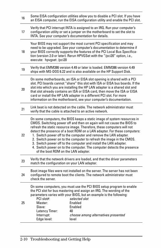
16 Some EISA configuration utilities allow you to disable a PCI slot. If you havean EISA computer, run the EISA configuration utility and enable the PCI slot.
17Verify that PCI interrupt INTA is assigned to an IRQ. Run your computer’sconfiguration utility or set a jumper on the motherboard to set the slot toINTA. See your computer’s documentation for details.
18
Your BIOS may not support the most current PCI specification and mayneed to be upgraded. See your computer’s documentation to determine ifyour BIOS correctly supports the features of the PCI Local Bus Specifica-tion (version 2.0 or later). Rerun HPVGSet with the “/pci20” option, i.e.,execute: hpvgset /pci20
19 Verify that EMM386 version 4.49 or later is loaded. EMM386 version 4.49ships with MS-DOS 6.22 and is also available on the HP Support Disk.
20
On some motherboards, an ISA or EISA slot opening is shared with a PCIslot. PCI boards cannot “share” this slot with ISA or EISA bus boards. If theslot into which you are installing the HP LAN adapter is a shared slot andthat slot already contains an ISA or EISA card, then move the ISA or EISAcard or install the HP LAN adapter in a different PCI slot. For moreinformation on the motherboard, see your computer’s documentation.
21 Link beat is not detected on the cable. The network administrator mustverify that the cable is attached to an active network.
22
On some computers, the BIOS keeps a static image of system resources inCMOS. Switching power off and then on again will not cause the BIOS torefresh the static resource image. Therefore, these computers will notdetect the presence of a boot ROM on a LAN adapter. For these computers: 1. Switch power off to the computer and remove the LAN adapter. 2. Switch power on to the computer to refresh the image in the CMOS. 3. Switch power off to the computer and install the LAN adapter. 4. Switch power on to the computer. The computer detects the presence
of the boot ROM on the LAN adapter.
23 Verify that the network drivers are loaded, and that the driver parametersmatch the configuration on your LAN adapter.
24Boot image files were not installed on the server. The server has not beenconfigured to remote boot the clients. The network administrator mustcheck the server.
25
On some computers, you must use the PCI BIOS setup program to enablethe PCI slot for bus mastering and assign an IRQ. The wording of theparameters varies with your BIOS, but an example is the following:
PCI slot#: selected slotMaster: EnabledSlave: EnabledLatency Timer: 40Interrupt: choose among alternatives presentedEdge level: level
2-10 Troubleshooting and Getting Help

26 Shut down the operating system, if running. Switch off the computer’spower and then switch it on again.
27 The network administrator must verify the network software configuration(Novell frame type, Microsoft workgroup name, IP address, etc.).
28
The LAN adapter may be defective. Try a different one. See the warrantyinformation accompanying your LAN adapter for exchange instructions ifyou have no alternate to try, or if the alternate works in place of thequestionable one.
Troubleshooting and Getting Help 2-11

Customer Service and Support
Getting Problems Resolved
Collect data before contacting your LAN dealer or Hewlett-Packard, as follows:
History of the Problem:What symptoms did you notice? Did the symptoms appear when the LAN adapter was firstinstalled, after normal operation, or after its configuration waschanged?If you changed its configuration, did you also change the driverparameters to match?
Card Configuration Information:Run HPVGSet. Select “Manual Configuration”. Record allparameters from the configuration listed.
Computer Information:What vendor and model of computer are you using?What are the processor speed and bus type (EISA/PCI orISA/PCI)?What is the configuration of other cards installed in yourcomputer?What operating system and version are you using?What network operating system and version are you using?What applications are running on the computer?If memory-mapped mode is being used, find out if an expandedmemory manager or memory caching is also running? If possible,get the memory manager to output a map of the computer’smemory.List the contents of key files such as autoexec.bat, autoexec.ncf,startup.ncf, config.sys, net.cfg, protocol.ini, lanman.ini, sys-tem.ini.
Hewlett-Packard offers services for end users’ LAN adapter prob-lems through automated electronic services (24 hours, seven days)and through direct phone assistance (during working hours), aslisted on the card at the beginning of this manual.
2-12 Troubleshooting and Getting Help

3
Reference forHP Support Disk
This reference chapter describes how to use the files and theutilities on the HP Support Disk.
All online information and software is accessible by using the Setuputility, “setup.exe”, on the support disk. Setup is a locator programthat organizes and helps you select:
the driver for each environment,
the configuration and testing functions in the utility namedHPVGSet, and
the complete instructions for installing, configuring, testing, andtroubleshooting all supported operating environments.
For the most common operating environments, chapter one of thismanual contains all the instructions needed to complete an installa-tion, and chapter two gives the troubleshooting information mostcommonly needed. Thus, you most likely will use the HP SupportDisk only to install the network driver and installation files—whenthe chapter one procedures instruct you to insert it—and will notneed to use Setup.
All users can start with chapter one. Its instructions identify theoperating systems, environments, special features and functions,and problems that may require you to use the more complete infor-mation and software accessible through Setup on the support disk.
This chapter contains operating information about the Setup utility,the HPVGSet utility, and describes some of the configuration andtesting options in HPVGSet.
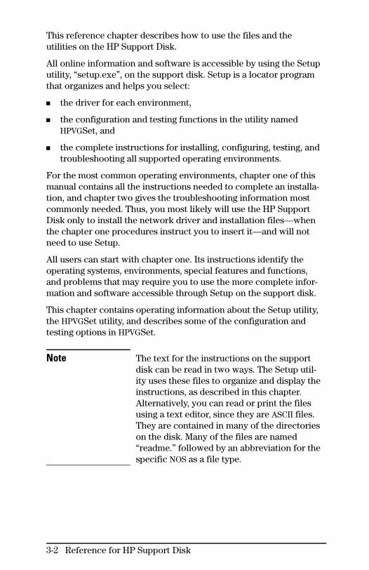
Note The text for the instructions on the supportdisk can be read in two ways. The Setup util-ity uses these files to organize and display theinstructions, as described in this chapter.Alternatively, you can read or print the filesusing a text editor, since they are ASCII files.They are contained in many of the directorieson the disk. Many of the files are named“readme.” followed by an abbreviation for thespecific NOS as a file type.
3-2 Reference for HP Support Disk

Setup Reference
Before Running Setup
You must be in DOS to run the “setup.exe” utility from theHP Support Disk.
Note One of Setup’s menu items has special DOSrequirements, while the others do not. Thatone is HPVGSet,which must run in native DOSwithout networking software or driversloaded. That procedure is described in“Before Running HPVGSet” on page 3-6.
An alternative to running HPVGSet fromwithin Setup is to use all Setup’s featuresexcept HPVGSet without any special require-ments, then exiting Setup, and then executingHPVGSet as a separate DOS utility after doingthe preparatory procedure on page 3-6.
Running Setup
Insert the HP Support Disk into the floppy drive, and change to thefloppy drive if necessary. Run Setup:
setup
Reference for HP Support Disk 3-3
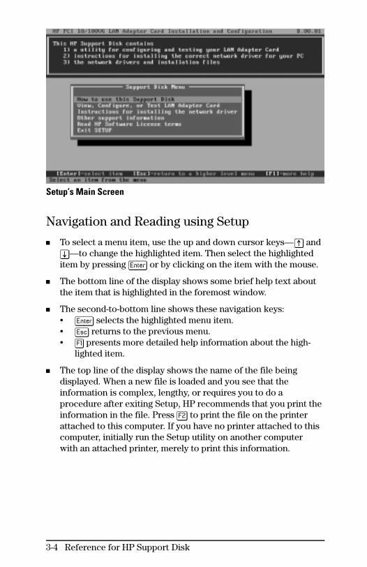
Setup’s Main Screen
Navigation and Reading using Setup
To select a menu item, use the up and down cursor keys—[^] and[v]—to change the highlighted item. Then select the highlighteditem by pressing [Enter] or by clicking on the item with the mouse.
The bottom line of the display shows some brief help text aboutthe item that is highlighted in the foremost window.
The second-to-bottom line shows these navigation keys:• [Enter] selects the highlighted menu item.• [Esc] returns to the previous menu.• [F1] presents more detailed help information about the high-
lighted item.
The top line of the display shows the name of the file beingdisplayed. When a new file is loaded and you see that theinformation is complex, lengthy, or requires you to do aprocedure after exiting Setup, HP recommends that you print theinformation in the file. Press [F2] to print the file on the printerattached to this computer. If you have no printer attached to thiscomputer, initially run the Setup utility on another computerwith an attached printer, merely to print this information.
3-4 Reference for HP Support Disk

Features in Setup
Complete driver installation instructions for all drivers—those inchapter 1 of this manual and all others, including NOS-related spe-cial configuration features.
Technical Notes: Other information, including full installation in-structions for all features and non-driver-related special configu-rations.
Access to HPVGSet for card and link testing, and when neededfor special configurations.
Reference for HP Support Disk 3-5
HPVGSet Reference
HPVGSet is an interactive configuration and diagnostics program onthe HP Support Disk that is shipped with the LAN adapter.
Before Running HPVGSet
You must exit to native DOS and/or boot your computer in nativeDOS with network software and drivers not loaded. The proceduredepends on your environment as listed below. After you finish run-ning HPVGSet, you can boot your computer normally.
Note You cannot run HPVGSet from a DOS windowwithin a Windows environment.
Decision:
If you run Microsoft Windows NT, OS/2, Novell NetWare on aserver, or Unix: Select the shutdown procedure and boot to DOS.Then perform alternative a, c, or d below.• If DOS is not installed, then perform alternative c below.
If you run Microsoft Windows 95: Perform alternative b, c, or dbelow.
If you run Microsoft Windows for Workgroups or MicrosoftWindows 3.x: Select the shutdown procedure or exit to DOS.Then perform alternative a, c, or d below.
If you run DOS only: Perform alternative a, c, or d below.
Clean boot alternatives:
a. If you run MS-DOS version 6.0 or later (use the DOS command“ver” to check), then boot and press the [F5] key when you seethe text “Starting MS-DOS....” You should then see “MS-DOS isbypassing your CONFIG.SYS and AUTOEXEC.BAT files”.
b. In Windows 95, shut down your computer. Cycle power. Pressthe [F8] key when you see the text “Starting Windows 95” atthe upper left of a blank screen. You should then see the“Microsoft Windows 95 Startup Menu”. Select option 7,
3-6 Reference for HP Support Disk

“Safe mode command prompt only”. You should then see theDOS prompt.
c. Boot from a DOS boot diskette, without “config.sys” or“autoexec.bat” files on it. See the DOS documentation forhelp.
d. If you understand how your network, drivers, and memorymanager are activated, then temporarily modify the “auto-exec.bat” and “config.sys” files so that these items do not
execute.
Running HPVGSet
There are two alternative ways to access the HPVGSet utility:
Run Setup from the HP Support Disk, according to the previoussection starting on page 3-3. Select the menu item “View,Configure, or Test LAN Adapter Card”.
From DOS, insert the HP Support Disk into the floppy drive,change to the floppy drive, and enter:
hpvgset
From either point of access, HPVGSet starts up and automaticallydetects the presence of HP LAN adapters.
In case of problems:
• If the preparatory procedure on the previous page was notfollowed, HPVGSet will fail to run and remind you of the DOSrequirements.
• If more than one LAN adapter from HP is detected, you willbe asked to select a specific adapter. Use the item “Selectcard” in the Main Menu to specify it.
The current configuration of the LAN adapter is detected anddisplayed, as in the example screen on the next page. The area at thetop of the screen labeled “Selected Card Status” displays the currentconfiguration of the LAN adapter. If you make changes to theconfiguration, the changes will be reflected in this area.
Reference for HP Support Disk 3-7
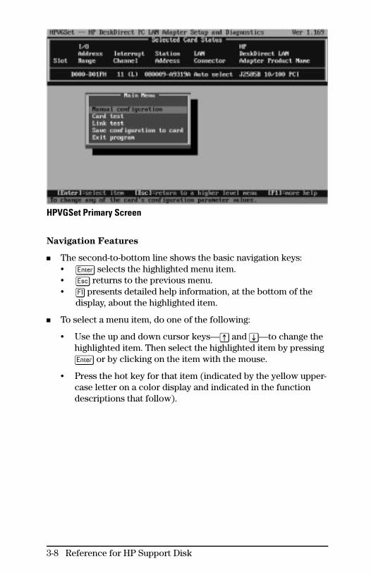
HPVGSet Primary Screen
Navigation Features
The second-to-bottom line shows the basic navigation keys:• [Enter] selects the highlighted menu item.• [Esc] returns to the previous menu.• [F1] presents detailed help information, at the bottom of the
display, about the highlighted item.
To select a menu item, do one of the following:
• Use the up and down cursor keys—[^] and [v]—to change thehighlighted item. Then select the highlighted item by pressing[Enter] or by clicking on the item with the mouse.
• Press the hot key for that item (indicated by the yellow upper-case letter on a color display and indicated in the functiondescriptions that follow).
3-8 Reference for HP Support Disk
HPVGSet Primary Screen Functions
Selected Card Status Area
If one HP LAN adapter is installed, HPVGSet immediately recognizesthe adapter and lists its product number and name in the last col-umn of the “Selected Card Status” area. The other columns displaythe configuration status of the adapter.
In case of problems:
• If more than one LAN adapter from HP is detected, use“Select Card” to select the specific adapter product toconfigure.
• If the LAN adapter is not found, follow the instructionsdisplayed by HPVGSet. Check the following likely possibilitiesand try the installation tasks again.
– Check that the adapter is plugged into a PCI connector,which is usually white and shorter than the other ISA orEISA type of connector.
– With the computer’s power switched off, reseat theadapter board, pushing it straight into the slot.
– Check that the PCI slot used is enabled, if the mother-board on your computer allows you to disable and enablePCI slots. Check your computer’s documentation for thispossibility.
For further help see chapter 2, “Troubleshooting”, fordiagnosis.
Reference for HP Support Disk 3-9

Main Menu
On the HPVGSet primary screen shown on page 3-8, the Main Menuitems may vary slightly, depending on the options currently relevant.
(The “hot key” listed for each menu item below can be typed toselect that item, and [F1] can be typed to read more detailed infor-mation. See “Navigation Features” on the previous page.)
select carD hot key [D]
Selects the LAN adapter to configure or test. This menu item isdisplayed only if you have installed multiple LAN adapters fromHP.
Manual configuration hot key [M]
Allows changing all configuration functions for the LAN adapter.See “Manual Configuration Functions” on the next page for moreinformation.
Card test hot key [C]
Tests the LAN adapter’s hardware and configuration. Does notsend packets on the network, so network cable need not beattached. See “Card Test” in chapter 2 on page 2-5 for more infor-mation.
Link test hot key [L]
Tests the LAN adapter’s ability to send and receive packets overthe network. Used to designate one HP adapter as the initiator ofthe test packets, and/or to designate another HP adapter as theresponder. (A smart hub will be automatically found as a re-sponder.) See “Running the Diagnostics in HPVGSet” in chapter 2on pages 2-4 to 2-7 for more information.
Save configuration to card hot key [S]
Writes the manual configuration (see above) to the adapter’snon-volatile memory.
Exit program hot key [E]
Terminates the HPVGSet session.
3-10 Reference for HP Support Disk

Manual Configuration Functions
When the “Manual configuration” menu item is selected from theMain Menu, the Manual Configuration Menu is displayed below theSelected Card Status display, as in the example below.
HPVGSet Manual Configuration Screen
Note Before configuring one of these functions,detach the LAN cable.
After configuring one of these functions,select “Exit Program”. Then from the MainMenu, select “Card test”, “Save configurationto card”, and “Exit Program”. Then attach thecable and boot the computer.
(The “hot key” listed for each menu item below can be typed toselect that item, and [F1] can be typed to read more detailedinformation. See “Navigation Features” on page 3-8.)
Boot ROM hot key [B]
Toggles between enabling and disabling (default) boot ROM.Install the HP J2582B Boot ROM on the adapter, using its docu-mentation. Then enable this function. After testing and savingthis configuration, you must switch off power, wait five seconds,switch on power, and then attach the cable.
Reference for HP Support Disk 3-11

BUs master hot key [U]
Toggles between enabling (default) and disabling bus mastermode, which allows direct data transfer between the adapter andthe computer’s memory, independently of the CPU. Bus master-ing yields higher performance.
I/O or Memory Mapped hot key [M]
Selects the alternative data transfer mode, either I/O-mapped ormemory-mapped, when bus mastering is not used. When mem-ory-mapped mode is selected, also specifies whether the addressregion is assigned by the PCI BIOS or from one of the legal mem-ory-mapped addresses. You have this option only when the busmaster option is disabled (see above).
10 Mbit/s Full Duplex hot key [D]
Toggles between disabling (default) or enabling full duplex,(sending and receiving simultaneously) for 10-Mbit/s networksonly (not 100VG). Full-duplex operation removes the through-put bottleneck for high-bandwidth devices such as servers,routers, bridges, and switches. When packets flow in both direc-tions simultaneously, effective bandwidth doubles from 10 to 20Mbit/s. Make sure the computer (commonly a server) is attachedto a switch or hub also configured for full-duplex operation.
LAN Connector hot key [C]
Specifies which speed is to be used on the twisted-pair connec-tor: "100 Mbit/s" or "10 Mbit/s", or "auto select" (default) for auto-matic detection of the speed of the attached network.
restore Factory default configuration hot key [F]
Restores the LAN adapter’s configuration to the values it hadwhen shipped from the factory.
Read configuration from disk file hot key [R]
Brings a configuration into HPVGSet from a disk file. Theconfiguration can be saved to this adapter by selecting “Saveconfiguration to card” in the Main Menu.
Write configuration to disk file hot key [W]
Writes the displayed configuration to a disk file that you cansubsequently use to configure LAN adapters.
Exit menu hot key [E]
Exits Manual Configuration Menu and returns to Main Menu.
3-12 Reference for HP Support Disk

A
Connectorsand Cables

This appendix includes minimum pin-out information for the twisted-pair connector and lists cables available from HP. All connectors onthe adapters adhere to the appropriate standards; you can alsopurchase cables from vendors such as Black Box and Anixter.
Note Incorrectly wired cabling is the most commoncause of problems for LAN communications.HP recommends that you work with a quali-fied LAN cable installer for assistance withyour cabling requirements.
Twisted-Pair RJ-45 Connector
Figure A-1. Illustration of RJ-45 Pins
10-Mbit/s Operation
Use unshielded twisted-pair cables that comply with the IEEE 802.3Type 10Base-T standard.
Pins Signal
1 (transmit +)2 (pair 2) (transmit –)3 (receive +)6 (pair 3) (receive –)
Available HP Cables
HP 92268A: 4 meters, with attached 8-pin connectorsHP 92268B: 8 meters, with attached 8-pin connectorsHP 92268C: 16 meters, with attached 8-pin connectorsHP 92268D: 32 meters, with attached 8-pin connectorsHP 92268N: 300 meters, no connectors supplied *
* IEEE 802.3 and Ethernet standards support up to 100 meters only.
A-2 Connectors and Cables
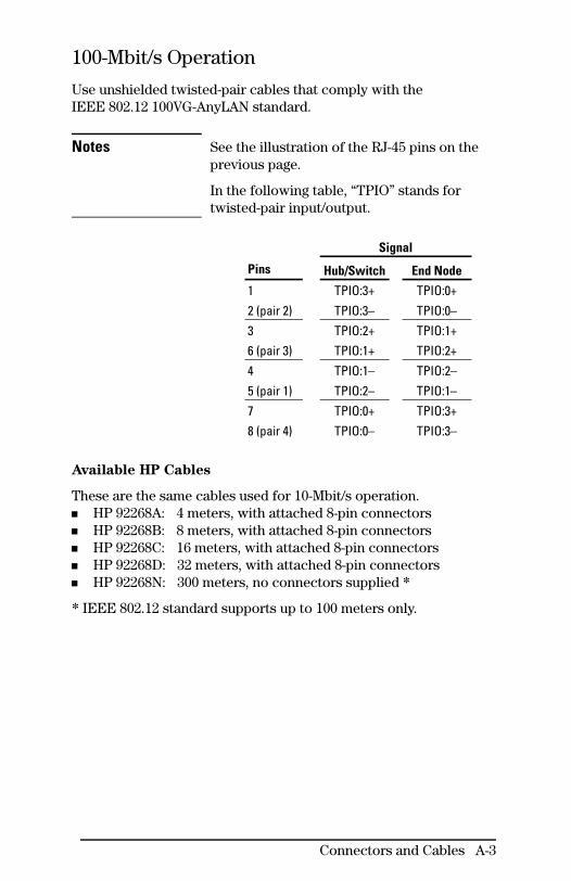
100-Mbit/s Operation
Use unshielded twisted-pair cables that comply with theIEEE 802.12 100VG-AnyLAN standard.
Notes See the illustration of the RJ-45 pins on theprevious page.
In the following table, “TPIO” stands fortwisted-pair input/output.
Signal
Pins Hub/Switch End Node
1 TPIO:3+ TPIO:0+2 (pair 2) TPIO:3– TPIO:0–3 TPIO:2+ TPIO:1+6 (pair 3) TPIO:1+ TPIO:2+4 TPIO:1– TPIO:2–5 (pair 1) TPIO:2– TPIO:1–7 TPIO:0+ TPIO:3+8 (pair 4) TPIO:0– TPIO:3–
Available HP Cables
These are the same cables used for 10-Mbit/s operation.HP 92268A: 4 meters, with attached 8-pin connectorsHP 92268B: 8 meters, with attached 8-pin connectorsHP 92268C: 16 meters, with attached 8-pin connectorsHP 92268D: 32 meters, with attached 8-pin connectorsHP 92268N: 300 meters, no connectors supplied *
* IEEE 802.12 standard supports up to 100 meters only.
Connectors and Cables A-3

ThinLAN BNC Connector
Figure A-2. Illustration of BNC Connector
10-Mbit/s Operation
Use thin coaxial cables that comply with the IEEE 802.3 Type10Base2 standard. Some RG-58 A/U and RG-58 C/U cables meetthese requirements.
The maximum length between nodes is 185 meters.The minimum length between nodes is one meter.
A-4 Connectors and Cables

B
Specifications

Physical
Dimensions Weight
J2585B 8.9 cm by 13.3 cm (3.5 in by 5.2 in) 89.4 g (3.2 oz)
J2970A 8.9 cm by 13.3 cm (3.5 in by 5.2 in) 96.2 g (3.4 oz)
J2973A 8.9 cm by 13.3 cm (3.5 in by 5.2 in) 78.2 g (2.8 oz)
Electrical
Typical Maximum
J2585B 0.43 A @ 5 V 0.50 A @ 5 V
J2970A 0.51 A @ 5 V 0.60 A @ 5 V
J2973A 0.32 A @ 5 V 0.40 A @ 5 V
Environmental
Operating Temperature Non-Operating Temperature
J2585BJ2970AJ2973A
0°C to 55°C (32°F to 131°F) -40°C to 70°C (-40°F to 158°F)
Relative Humidity Maximum Altitude
J2585BJ2970AJ2973A
15% to 95% at 40°C (104°F)non-condensing 4.6 km (15,000 feet)
B-2 Specifications

Electromagnetic
EmissionsCountry Class
J2585BJ2970AJ2973A
USA, Canada, Latin America FCC part 15 Class B orCISPR-22/EN 55022 Class B
Europe and others CISPR-22/EN 55022 Class B
Japan VCCI level 2
Immunity See the Declaration of Conformity in Appendix C,“Regulatory Statements”, at the end of this guide.
See also the Canadian declaration in Appendix C,“Regulatory Statements”, at the end of this guide.
Acoustic Noise
Not applicable
Data Communications
Cable Interface Specification
J2585B Twisted-pair RJ-45 IEEE 802.3 Type 10Base-TIEEE 802.12 100VG-AnyLAN
J2970ATwisted-pair RJ-45 IEEE 802.3 Type 10Base-T
ThinLAN BNC IEEE 802.3 Type 10Base2
J2973A Twisted-pair RJ-45 IEEE 802.3 Type 10Base-T
Specifications B-3


C
Regulatory Statements
FCC RFI Statement (For U.S.A. Only)
Federal Communications Commission Radio Frequency
Interference Statement
Warning: This equipment generates, uses, and can radiate radiofrequency energy. If it is not installed and used in accordance withthe instruction manual, it may cause interference to radio communi-cations. It has been tested and found to comply with the limits for aClass B computing device pursuant to Part 15 of FCC Rules, whichare designed to provide reasonable protection against harmful inter-ference in a residential environment.
This device complies with Part 15 of the FCC Rules.Operation is subject to the following two conditions:(1) This device may not cause harmful interference, and(2) This device must accept any interference received, including interference that may cause undesired operation.
If this equipment causes interference to radio reception (which canbe determined by unplugging the power cord from the equipment)try these measures: Re-orient the receiving antenna. Relocate theequipment with respect to the receiver. Plug the equipment andreceiver into different branch circuits. Consult your dealer or anexperienced technician for additional suggestions.
C-2 Regulatory Statements

VCCI 2 (For Japan Only)
Canada
This product complies with Canadian EMC requirements.
Korea
Regulatory Statements C-3

Declaration of Conformity
The Declaration of Conformity below complies with ISO/IEC Guide22 and EN 45014. It identifies the product, the manufacturer’s nameand address, and the applicable specifications that are recognized inthe European community.
C-4 Regulatory Statements

Index
Symbols
0x for hexadecimal in WFWG ...1-1410-Mbit/s
See also 100VGconnection ...A-2, A-4full duplex ...1-5LED ...2-3pinouts for RJ-45 ...A-2
100-Mbit/sSee also 100VGconnection ...A-3LED ...2-3pinouts for RJ-45 ...A-3
100VGSee also 100-Mbit/sadapter ...0-iiicabling ...A-3LED ...2-3standard ...0-iv, A-3upgrading ...0-viiiwith Novell VLM ...1-18
10Base-T ...A-2, B-310Base2 ...0-iv, A-4, B-3
A
Act LED ...2-3Add New Hardware wizard ...1-9address, I/O ...1-10–1-11, 1-14address, MAC ...2-7antistatic procedure ...1-4autoconfiguration of adapter ...1-5,1-7, 1-10autodetection of HP adapter ...1-5,1-7, 1-10–1-11, 3-7autodetection of LAN speed ...0-iv
B
base I/O address ...1-10–1-11, 1-14BNC ThinLAN connector ...0-iv,1-4–1-5, A-4boot cleanly (without networking)...1-20, 1-23, 2-4, 3-6–3-7boot disk ...1-20, 1-23, 2-4, 3-7boot ROM ...0-iv, 2-8, 2-10, 3-11bus
master ...0-iv, 2-5, 3-12See also PCI
C
cable ...1-4–1-5, A-1–A-4100VG requirements ...0-viiiinstallation ...1-2, 1-4–1-5interfaces ...B-3sources ...A-2–A-4
Canadian EMC ...C-2card test in HPVGSet ...2-4–2-5, 2-8,3-10CD-ROM
NetWare ...1-19Novell DOS Shell installation ...1-23Windows 95 ...1-8
CISPR ...B-3client setup ...1-6–1-7, 1-18coaxial cabling
See thin coaxial cablingCompuServe for updated files...1-23configuration
access from Setup ...1-2, 1-11, 3-5automatic ...1-5, 1-7, 1-10loading into HPVGSet ...3-12options documented on line ...1-2options in HPVGSet ...3-10–3-12restoring HPVGSet defaults ...3-12saving in HPVGSet ...3-10, 3-12shown in HPVGSet ...1-11, 3-7writing onto disk ...3-12
connectors ...0-iv, 1-4–1-5, A-1–A-4customer support ...2-12
D
data communicationsspecifications ...B-3data transfer mode ...0-iv
bus master ...0-iv, 2-5, 3-12I/O mapped mode ...0-iv, 2-5, 3-12memory mapped mode ...0-iv, 2-5,
3-12declaration of conformity ...C-4diagnosis ...2-1–2-12
adapter not detected ...3-9answers ...2-9–2-11card test in HPVGSet ...2-4–2-5, 3-10from LEDs ...2-3HPVGSet problems ...2-8link test in HPVGSet ...2-4–2-7, 3-10
2 Index
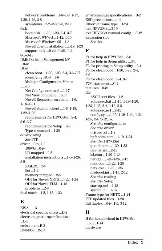
network problems ...1-8–1-9, 1-17,1-20, 1-26, 2-8
symptoms ...2-2–2-3, 2-8, 2-12disk
boot disk ...1-20, 1-23, 2-4, 3-7Microsoft WFWG ...1-12, 1-15Microsoft Windows 95 ...1-8Novell client installation ...1-19, 1-23support disk ...0-vii–0-viii, 1-2,
3-1–3-12DMI: Desktop Management I/F...0-ivDOS
clean boot ...1-20, 1-23, 2-4, 3-6–3-7identifying NOS ...1-6Multiple Configuration Menus
...1-15Net Config command ...1-17Net View command ...1-17Novell Requestor on client ...1-6,
1-18–1-21Novell Shell on client ...1-6, 1-18,
1-22–1-26requirements for HPVGSet ...2-4,
3-6–3-7requirements for Setup ...3-3Type command ...1-25
downloadingSee FTP
driver ...0-iv, 1-2100VG ...0-ivI/O mapped ...2-5installation instructions ...1-6–1-26,
3-5IOMEM ...2-5list ...1-2memory mapped ...2-5ODI for Novell NETX ...1-22, 1-24ODI for Novell VLM ...1-18problems ...2-8
dual stack ...1-2, 1-18, 1-22
E
EISA ...1-3electrical specifications ...B-2electromagnetic specifications...B-3emissions ...B-3EMM386 ...2-10
environmental specifications ...B-2ESD precautions ...1-4Ethernet frame type ...1-24exit HPVGSet ...3-10exit HPVGSet manual config. ...3-12expansion slot
See slot
F
F1 for help in HPVGSet ...3-8F1 for help in Setup utility ...3-4F2 for printing in Setup utility ...3-4F5 for clean boot ...1-20, 1-23, 2-4,3-6F8 for clean boot ...2-4, 3-7FCC statement ...C-2features ...0-ivfile
ASCII text files ...1-2autoexec.bat ...1-15, 1-19–1-20,
1-23, 1-25, 2-4, 2-12, 3-6autoexec.ncf ...2-12config.sys ...1-15, 1-19–1-20, 1-23,
1-25, 2-4, 2-12, 3-6See also configurationSee also driverdrivers.txt ...1-2hpfeodim.com ...1-19, 1-24See also HPVGSetipxodi.com ...1-20–1-23lanman.ini ...2-12lsl.com ...1-20–1-23net.cfg ...1-24–1-25, 2-12netx.com ...1-22, 1-25netx.exe ...1-22, 1-25protocol.ini ...1-15, 2-12See also readingSee also Setupstartup.ncf ...2-12system.ini ...1-15
Frame type for NETX ...1-24FTP updated files ...1-23full duplex ...0-iv, 1-5, 3-12
H
H for hexadecimal in HPVGSet...1-11, 1-14hardware
Index 3
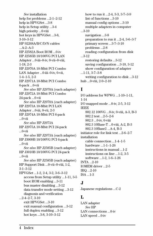
See installationhelp for problems ...2-1–2-12help in HPVGSet ...3-8help in Setup utility ...3-4high priority ...0-viiihot keys in HPVGSet ...3-8,3-10–3-12HP 92268A/B/C/D/N cables...A-2–A-3HP J2582A Boot ROM ...0-ivHP J2585B 10/100VG PCI LANAdapter ...0-iii–0-iv, 0-vii–0-viii,1-18, 2-3HP J2970A 10-Mbit PCI ComboLAN Adapter ...0-iii–0-iv, 0-vii,1-4–1-5, 2-3HP J2971A 10-Mbit PCI Combo6-pack ...0-vii
See also HP J2970A (each adapter)HP J2972A 10-Mbit PCI Combo24-pack ...0-vii
See also HP J2970A (each adapter)HP J2973A 10-Mbit PCI LANAdapter ...0-iii, 0-vii, 2-3HP J2974A 10-Mbit PCI 6-pack...0-vii
See also HP J2973AHP J2975A 10-Mbit PCI 24-pack...0-vii
See also HP J2973A (each adapter)HP J3009B 10/100VG PCI 6-pack...0-vii
See also HP J2585B (each adapter)HP J3010B 10/100VG PCI 24-pack...0-vii
See also HP J2585B (each adapter)HP Support Disk ...0-vii–0-viii, 1-2,3-1–3-12HPVGSet ...1-2, 2-4, 3-2, 3-6–3-12
access from Setup utility ...1-11, 3-5boot ROM enabling ...3-11bus master disabling ...3-12data transfer mode setting ...3-12diagnosis and verification
...2-4–2-7, 3-10exit HPVGSet ...3-10exit manual configuration ...3-12full duplex enabling ...3-12hot keys ...3-8, 3-10–3-12
how to run it ...2-4, 3-3, 3-7–3-9list of functions ...3-10manual config options ...3-10multiple adapters in computer
...3-10navigation ...3-8preparation to run it ...2-4, 3-6–3-7primary screen ...3-7–3-10problems ...2-8reading configuration from disk
...3-12restoring defaults ...3-12saving configuration ...3-10, 3-12show configuration of adapter
...1-11, 3-7–3-8writing configuration to disk ...3-12
hub ...0-viii, 2-9–2-10
I
I/O address for WFWG ...1-10–1-11,1-14I/O mapped mode ...0-iv, 2-5, 3-12IEEE
802.12 100VG ...0-iv, 0-viii, A-3, B-3802.2 test ...2-5–2-6802.3 ...0-iv, 0-viii802.3 10Base-T ...0-viii, A-2, B-3802.3 10Base2 ...A-4, B-3
initiator role for link test ...2-6–2-7installation
cable connection ...1-4–1-5hardware ...1-1–1-26instructions in manual ...1-2instructions on line ...1-2, 3-5software ...1-2, 1-6–1-26
INTA ...2-10IOMEM driver ...2-5IRQ ...2-10ISA ...1-3
J
Japanese regulations ...C-2
L
LAN adapterSee HP
LAN connections ...0-ivLAN speed ...0-iv
4 Index

lastdrive statement ...1-25LED ...0-iv, 2-3link beat on attached hub ...2-9–2-10Link LED ...2-3, 2-8link test in HPVGSet ...2-4–2-8, 3-10
M
MAC address ...2-7Main Menu ...3-8, 3-10–3-12manual configuration in HPVGSet...3-10–3-12memory-mapped mode ...0-iv, 2-5,3-12menu in HPVGSet ...3-7–3-8,3-10–3-11menu in Setup ...3-4Microsoft Windows 3.x ...1-6
with Novell VLM ...1-19Microsoft Windows 95 ...1-6–1-9
preparation for HPVGSet ...2-4,3-6–3-7
installation or upgrading ...1-3, 1-7,1-9Microsoft Windows forWorkgroups ...1-6, 1-10–1-17
installation ...1-12Microsoft Windows NT withHPVGSet ...2-4, 3-6multiple adapters installation ...1-2,1-20, 1-25, 3-10
N
navigation in HPVGSet ...3-8navigation in Setup utility ...3-4Net Config command ...1-17Net View command ...1-17NetWare
See NovellNetWire for Novell ...1-23network management ...0-ivNETX ...1-22–1-26New Hardware Found ...1-7–1-9nodal high priority for 100VG...0-viiiNOS: network operating system...0-iv, 1-2, 3-2
identifying your NOS ...1-6, 1-18Microsoft Windows 95 ...1-3
Novell NetWare with HPVGSet...2-4, 3-6Novell NOS
DOS client ...1-6, 1-18DOS Requestor (VLM) ...1-6,
1-18–1-21DOS Shell (NETX) ...1-6, 1-18,
1-22–1-26NetWare on server ...1-6, 1-19updating files ...1-18, 1-20–1-23VLM overrides ...1-20with Microsoft WFWG ...1-18, 1-22with Microsoft Windows 95 ...1-7
O
ODI driver for Novell NETX ...1-22ODI driver for Novell VLM ...1-18online help in HPVGSet ...3-8online help in Setup utility ...3-4operating system
See NOSOS/2 with HPVGSet ...2-4, 3-6overrides in VLM installation ...1-20overview ...0-iii, 1-2
P
parts list ...0-viipassword in Windows 95 ...1-8password in Windows forWorkgroups ...1-16PCI: Peripheral ComponentInterconnect
connector ...1-3–1-4enabling ...2-9, 3-9slot ...1-2version ...0-iv, 2-10
pinouts ...A-2–A-3PIO
See I/O mapped modepower consumption ...B-2printing info on support disk ...3-4priority, 100VG high priority ...0-viiiprogrammed I/O mode
See I/O mapped mode
R
radio frequency interference ...C-2read configuration into HPVGSet
Index 5
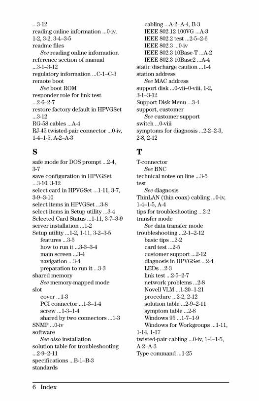
...3-12reading online information ...0-iv,1-2, 3-2, 3-4–3-5readme files
See reading online informationreference section of manual...3-1–3-12regulatory information ...C-1–C-3remote boot
See boot ROMresponder role for link test...2-6–2-7restore factory default in HPVGSet...3-12RG-58 cables ...A-4RJ-45 twisted-pair connector ...0-iv,1-4–1-5, A-2–A-3
S
safe mode for DOS prompt ...2-4,3-7save configuration in HPVGSet...3-10, 3-12select card in HPVGSet ...1-11, 3-7,3-9–3-10select items in HPVGSet ...3-8select items in Setup utility ...3-4Selected Card Status ...1-11, 3-7–3-9server installation ...1-2Setup utility ...1-2, 1-11, 3-2–3-5
features ...3-5how to run it ...3-3–3-4main screen ...3-4navigation ...3-4preparation to run it ...3-3
shared memorySee memory-mapped mode
slotcover ...1-3PCI connector ...1-3–1-4screw ...1-3–1-4shared by two connectors ...1-3
SNMP ...0-ivsoftware
See also installationsolution table for troubleshooting...2-9–2-11specifications ...B-1–B-3standards
cabling ...A-2–A-4, B-3IEEE 802.12 100VG ...A-3IEEE 802.2 test ...2-5–2-6IEEE 802.3 ...0-ivIEEE 802.3 10Base-T ...A-2IEEE 802.3 10Base2 ...A-4
static discharge caution ...1-4station address
See MAC addresssupport disk ...0-vii–0-viii, 1-2,3-1–3-12Support Disk Menu ...3-4support, customer
See customer supportswitch ...0-viiisymptoms for diagnosis ...2-2–2-3,2-8, 2-12
T
T-connectorSee BNC
technical notes on line ...3-5test
See diagnosisThinLAN (thin coax) cabling ...0-iv,1-4–1-5, A-4tips for troubleshooting ...2-2transfer mode
See data transfer modetroubleshooting ...2-1–2-12
basic tips ...2-2card test ...2-5customer support ...2-12diagnosis in HPVGSet ...2-4LEDs ...2-3link test ...2-5–2-7network problems ...2-8Novell VLM ...1-20–1-21procedure ...2-2, 2-12solution table ...2-9–2-11symptom table ...2-8Windows 95 ...1-7–1-9Windows for Workgroups ...1-11,
1-14, 1-17twisted-pair cabling ...0-iv, 1-4–1-5,A-2–A-3Type command ...1-25
6 Index

U
Unix with HPVGSet ...2-4, 3-6updating Novell files ...1-18,1-20–1-23upgrading to 100VG ...0-viiiupgrading to Windows 95 ...1-3, 1-7,1-9utilities with LAN adapter ...1-2,3-1–3-12
V
vcci ...B-3, C-2verification
hardware installation ...2-4–2-7, 3-5,3-10
Novell NETX ...1-26Novell VLM ...1-20–1-21software & hardware installation
...0-viii, 1-8–1-9, 1-17, 1-20–1-21, 1-26Windows 95 ...1-8–1-9Windows for Workgroups ...1-17
Version command in DOS ...1-20,1-23, 2-4, 3-6version, checking Novell files...1-18, 1-21–1-23View, Configure, or Test ... ...3-7VLM ...1-18–1-21
W
WindowsSee Microsoft Windows
wizard for Windows 95 ...1-9write configuration in HPVGSet...3-12WWW: World Wide Web ...1-23
Index 7


Copyright © 1997Hewlett-Packard CompanyPrinted in Singapore 10/97
Manual Part Number5967-0892
*5967-0892*