hp laserjet p2015 series maintenance kit instructions ...€¦ · replace the pickup roller and...
TRANSCRIPT

Replace the pickup roller and separation pad (Tray 1)1.
2.
Press the print-cartridge-door button to open the print-cartridge door.
3.
Remove the print cartridge. After removing the print cartridge, only handle it on the ends.
Grasping the pickup-roller cover with thumb and forefinger, squeeze the left side of the pickup-roller cover to release the left retaining tab, and then slide the cover to the left and up.
CAUTION Failure to slide the cover to the left when removing it can cause the rightretaining tab to break.
HP LaserJet P2015 seriesMaintenance Kit Instructions
www.printertechs.com page 1 / 33

Press the two black retaining tabs outward until the pickup roller is released from its seat.4.
5. Remove the old pickup roller from the printer.
6. Insert a flatblade screwdriver under the old separation pad and pry up to remove it.
www.printertechs.com page 2 / 33

8. Line up the black retaining tabs in the printer with the grooves in the new pickup roller, and thenpress the pickup roller into the pickup-roller seat until the retaining tabs click.
Note: Do not touch the pickup-roller pad.
Install the new separation pad. Insert as shown in picture below, then use the flatblade of your7.screwdriver (or your fingers) to firmly press down and lock both sides of the separation pad.
www.printertechs.com page 3 / 33

9. Grasping the pickup-roller cover with thumb and forefinger, insert the pickup-roller cover's rightretaining tab into the retaining slot.
10. Squeeze the left side of the pickup-roller cover and insert the left retaining tab in the retainingslot.
11. Close the print-cartridge door.
www.printertechs.com page 4 / 33

Replace the pickup roller (tray 2)1. Remove tray 2.
2. Open the automatic two-sided path door on the front of the printer (HP LaserJet P2015d,HP LaserJet P2015dn, and HP LaserJet P2015x printers only).
3. Place the printer on the work surface with the front of the printer facing up.
www.printertechs.com page 5 / 33

4. Pull the white tabs outward, and rotate the tabs up.
5. Slide the right tab to the right, and leave the tab in this position throughout the procedure.
www.printertechs.com page 6 / 33

5. Slide the pickup roller assembly to the right, and remove the left end cap.
6. Remove the old pickup roller.
Note: Save both idler rollers that sit on either side of the pickup roller; transfer to new roller.
www.printertechs.com page 7 / 33

7. Insert the left side of the new pickup roller into the left slot (1), and insert the right side (the sidethat has the notches in the shaft) into the right slot (2).
8. Place the end cap over the shaft on the left side, push the end cap to the right, and rotate thetab downward into position.
9. Rotate the shaft until the notches engage and the shaft clicks into place.
10. Push the right tab to the left, and rotate the tab downward into position.
www.printertechs.com page 8 / 33

1. Remove the cassette paper tray (tray 2) from the printer.
2. Remove the 2 screws (circled in picture below) which secure the separation pad.
3. Remove the old separation pad assembly. Insert the new assembly and replace the screws.
CoversCovers
Tray 2 Separation Pad
www.printertechs.com page 9 / 33

CoversLeft-side cover1. Open the print-cartridge door.
2. At the back of the printer, use a flat-blade screwdriver to release two tabs (1).
Figure 6-1 Removing the left-side cover (1 of 2)
3. Lift the cover away from the printer.
Right-side cover1. Open the print-cartridge door.
2. Remove tray 2.
www.printertechs.com page 10 / 33

3. At the front of the printer, pop the front edge of the right-side cover over the two retaining tabs.
Figure 6-2 Removing the right-side cover
4. Lift the cover away from the printer.
Back cover1. Remove tray 2.
2. Remove the left-side cover and the right-side cover.
www.printertechs.com page 11 / 33

3. Remove four screws (1).
Figure 6-3 Removing the back cover (1 of 2)
4. Tip the printer so that it rests on its front.
5. Release the tab (2) at the back of the printer on the right side.
6. Open the duplex access door (3).
www.printertechs.com page 12 / 33

7. Slide the cover toward the right side of the printer to clear the tab (1) on the duplexer tray(duplex models only).
Figure 6-4 Removing the back cover (2 of 2)
8. Lift the cover straight up and away from the printer.
Duplexer tray (HP LaserJet P2015d, P2015dn, and P2015x printersonly)1. Remove the left-side cover, the right-side cover, and the back cover.
www.printertechs.com page 13 / 33

2. Pull the duplexer tray release-tab (1) to release the duplexer tray magnets.
Figure 6-5 Removing the duplexer tray
3. Pull out the duplexer tray.
Top cover1. Remove the left-side cover, the right-side cover, the back cover, and the duplexer tray.
www.printertechs.com page 14 / 33

2. Remove two screws (1) at the back of the printer.
Figure 6-6 Removing the top cover (1 of 4)
www.printertechs.com page 15 / 33

3. Remove one screw (1) on the left side of the printer, and remove one screw (2) on the right sideof the printer.
Figure 6-7 Removing the top cover (2 of 4)
www.printertechs.com page 16 / 33

4. Release the control-panel cable (1) on the left side of the printer.
Figure 6-8 Removing the top cover (3 of 4)
www.printertechs.com page 17 / 33

5. Lift the top cover off the printer.
Figure 6-9 Removing the top cover (4 of 4)
www.printertechs.com page 18 / 33

FuserSeveral parts must be removed before you can remove the fuser. The following parts are included inthis section about removing the fuser:
● Fan
● Duplex-drive gears/face-down gears
● Duplex solenoid
● Fuser
Fan1. Remove all covers.
2. Disconnect the fan cable (1) at the ECU.
Figure 6-18 Removing the fan (1 of 2)
3. Unthread the fan wires from the retaining clips.
4. Remove two screws (1).
www.printertechs.com page 19 / 33

5. Unhook the fan clip (2) and then lift the fan off the printer.
Figure 6-19 Removing the fan (2 of 2)
www.printertechs.com page 20 / 33

3. Remove three screws (1).
Figure 6-20 Removing the duplex-drive gears (1 of 2)
Duplex-drive gears (HP LaserJet P2015d, P2015dn, and P2015xprinters only)1. Remove all covers.
2. Remove the fan.
www.printertechs.com page 21 / 33
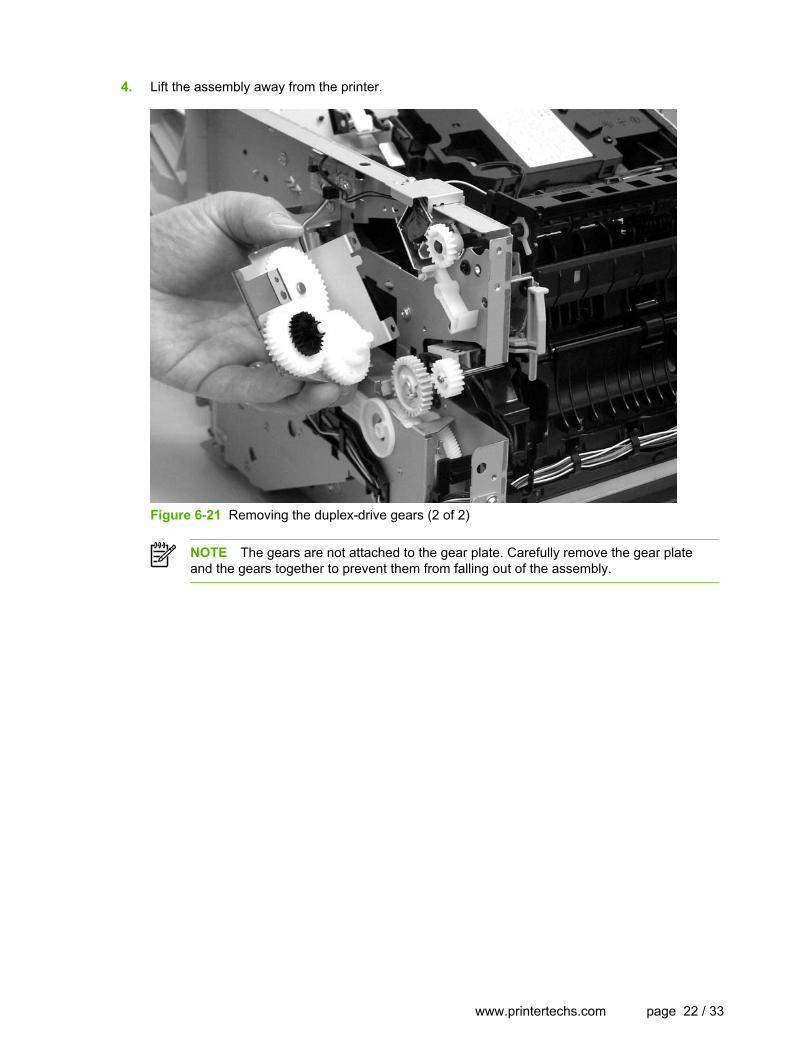
4. Lift the assembly away from the printer.
Figure 6-21 Removing the duplex-drive gears (2 of 2)
NOTE The gears are not attached to the gear plate. Carefully remove the gear plateand the gears together to prevent them from falling out of the assembly.
www.printertechs.com page 22 / 33

5. Remove one screw (2), and then lift the solenoid off the printer chassis.
Figure 6-22 Removing the duplex solenoid
Duplex solenoid (HP LaserJet P2015d, P2015dn, and P2015xprinters only)1. Remove all covers.
2. Remove the fan.
3. Remove the duplex-drive gears.
4. Disconnect one cable (1) at the duplex-drive PCA.
www.printertechs.com page 23 / 33

6. Disconnect one cable (2) on the right side of the printer.
Figure 6-23 Removing the fuser (1 of 10)
Fuser1. Remove all covers.
2. Remove the fan.
3. Remove the duplex-drive gears or face-down gears.
4. Remove the formatter.
5. On the right side of the printer, press the tabs on two gears (1) to release the gears, and thenslide the gears off the shafts.
www.printertechs.com page 24 / 33

7. Disconnect four cables (1) from the ECU, and then disconnect two more cables (2) that werebehind the first set.
Figure 6-24 Removing the fuser (2 of 10)
8. Pull the tab on the cable holder (1) at the left side of the printer and slide it toward the center torelease it from the frame, and then unroute the cables.
www.printertechs.com page 25 / 33

9. Pull the tab on the cable holder (2) and slide it toward the center to release it from the frame,and then unroute the cables.
Figure 6-25 Removing the fuser (3 of 10)
www.printertechs.com page 26 / 33

10. Remove one screw (1) from the fuser cover, and then slide the fuser cover to the right andremove it.
Figure 6-26 Removing the fuser (4 of 10)
www.printertechs.com page 27 / 33

11. Disconnect three cables (1).
Figure 6-27 Removing the fuser (5 of 10)
www.printertechs.com page 28 / 33

12. Disconnect one cable (1), and then unroute the cable from the cable guide.
Figure 6-28 Removing the fuser (6 of 10)
NOTE Before you proceed to step 13, make sure that all cables disconnected inprevious steps are free from any cable guides and cable holders.
www.printertechs.com page 29 / 33

13. Remove three screws (1) on the right side of the printer.
Figure 6-29 Removing the fuser (7 of 10)
www.printertechs.com page 30 / 33

14. Remove three screws (1) from the left side of the printer.
Figure 6-30 Removing the fuser (8 of 10)
www.printertechs.com page 31 / 33

15. At the left side of the printer, pull the printer chassis from the top to spread the printer frame andrelease the fuser from the frame.
Figure 6-31 Removing the fuser (9 of 10)
www.printertechs.com page 32 / 33

16. Pull the fuser out of the printer at an angle so that the delivery roller shaft clears the hole (1) inthe chassis.
Figure 6-32 Removing the fuser (10 of 10)
www.printertechs.com page 33 / 33