hp 5890 series ii and hp 5890 series ii plus · 2016-09-08 · c temperature programming. inlet...
TRANSCRIPT

ProgrammableCool On-Column
HP 5890 Series II andHP 5890 Series II Plus

Little Falls SiteHewlett-Packard Company2850 Centerville RoadWilmington, DE 19808-1610
DHewlett-PackardCompany 1989, 1990, 1991,1992, 1993, 1994
All Rights Reserved.Reproduction, adaptation,or translation withoutpermission is prohibited,except as allowed underthe copyright laws.
HP part number19245-90300
First edition—Jun 1989Second edition—Aug 1989Third edition—Jan 1990Fourth edition—Oct 1990Fifth edition—Sep 1991Sixth edition—Oct 1991Seventh edition—Jun 1992Eighth edition—Sep 1992Ninth edition— Jun 1993Tenth edition—Jul 1994
Printed in USA
WarrantyThe information containedin this document is subjectto change without notice.
Hewlett-Packard makes nowarranty of any kind withregard to this material,including, but not limitedto, the implied warrantiesof merchantability andfitness for a particularpurpose. Hewlett-Packardshall not be liable for errorscontained herein or forincidental or consequentialdamages in connection withthe furnishing,performance, or use of thismaterial.
Safety InformationThe HP 5890 Series II andHP 5890 Series II Plus areIEC (InternationalElectrotechnicalCommission) Safety Class 1instruments. This unit hasbeen designed and tested inaccordance with recognizedsafety standards. Wheneverthe safety protection of theHP 5890 Series II has beencompromised, disconnectthe unit from all powersources and secure the unitagainst unintendedoperation.
Safety SymbolsThis manual containssafety information thatshould be followed by theuser to ensure safeoperation.
WARNING
A warning calls attentionto a condition or possiblesituation that could causeinjury to the user.
CAUTION
A caution calls attention toa condition or possiblesituation that coulddamage or destroy theproduct or the user’s work.
Important UserInformation for In VitroDiagnostic ApplicationsThis is a multipurposeproduct that may be usedfor qualitative orquantitative analyses inmany applications. If usedin conjunction with provenprocedures (methodology)by qualified operator, oneof these applications maybe In Vitro DiagnosticProcedures.Generalized instrumentperformance characteristicsand instructions areincluded in this manual.Specific In Vitro Diagnosticprocedures andmethodology remain thechoice and theresponsibility of the user,and are not included.
Sound EmissionCertification for FederalRepublic of GermanyIf Test and MeasurementEquipment is operated withunscreened cables and/orused for measurements inopen set-ups, users have toassure that under theseoperating conditions theRadio Interference Limitsare still met at the borderof their premises.The following informationis provided to comply withthe requirements of theGerman Sound EmissionDirective dated January 18,1991Sound pressure Lp <70db(A)During normal operationAt the operator positionAccording to ISO 7779(Type Test)When operating the HP5890 Series II with cryovalve option, the soundpressure � 78 db(A) duringcryo valve operation forshort burst pulses.
SchallemissionWerden Meß- undTestgeräte mitungeschirmten Kabelnund/oder in offenenMeßaufbauten verwendet,so ist vom Betreibersicherzustellen, daß dieFunk-Entströbedingungenunter Betriebsbedingungenan seinerGrundstücksgrenzeeingehalten werden.Diese Information steht imZusammenhang mit denAnforderungen derMaschinenlärminformationsverordnung vom 18Januar 1991.Schalldruckpegel LP < 70dB(A)Am ArbeitsplatzNormaler BetriebNach DIN 45635 T. 19(Typprüfung)Bei Betrieb des HP 5890Serie II mit Cryo VentilOption treten beim Oeffnendes Ventils impulsfoermigSchalldrucke Lp bis ca. 78dB(A) auf.

Contents
Chapter 1 — What is the Cool OnColumn Inlet? 5. . . . .Features of the HP cool on-column inlet 8. . . . . . . . . . . . . . . . . . . . . . . . . . . . . . . . .
Chapter 2 — Using the Correct Insert, Needle Guide,and Septum 11. . . . . . . . . . . . . . . . . . . . . . . . . . . .
Selecting the correct insert 12. . . . . . . . . . . . . . . . . . . . . . . . . . . . . . . . . . . . . . . . . . . . .Changing the needle guide and septum 13. . . . . . . . . . . . . . . . . . . . . . . . . . . . . . . . . .Selecting the correct needle support assembly 15. . . . . . . . . . . . . . . . . . . . . . . . . . . .Using retention gaps and other precolumns 16. . . . . . . . . . . . . . . . . . . . . . . . . . . . . .
Chapter 3 — Installing Columns 19. . . . . . . . . . . . . . . . . . . . .Preparing a fused silica capillary column 21. . . . . . . . . . . . . . . . . . . . . . . . . . . . . . . .Checking the needle-to-column size 22. . . . . . . . . . . . . . . . . . . . . . . . . . . . . . . . . . . .Installing the insert 23. . . . . . . . . . . . . . . . . . . . . . . . . . . . . . . . . . . . . . . . . . . . . . . . . . .Aligning the inlet septum nut 25. . . . . . . . . . . . . . . . . . . . . . . . . . . . . . . . . . . . . . . . . .Installing the needle into the syringe barrel for automatic injection 26. . . . . . . .Installing a fused silica capillary column for automatic injection 27. . . . . . . . . . .Checking for column installation problems 29. . . . . . . . . . . . . . . . . . . . . . . . . . . . . . .
Chapter 4 — Setting Inlet Pressure 31. . . . . . . . . . . . . . . . . .Selecting the best inlet pressure 32. . . . . . . . . . . . . . . . . . . . . . . . . . . . . . . . . . . . . . . .Setting inlet pressure using electronic pressure control 34. . . . . . . . . . . . . . . . . . .Using the constant mass flow modes 38. . . . . . . . . . . . . . . . . . . . . . . . . . . . . . . . . . . .Setting mass flow rate 39. . . . . . . . . . . . . . . . . . . . . . . . . . . . . . . . . . . . . . . . . . . . . . . . .Determining the corrected column length 41. . . . . . . . . . . . . . . . . . . . . . . . . . . . . . . .Setting flow programs 42. . . . . . . . . . . . . . . . . . . . . . . . . . . . . . . . . . . . . . . . . . . . . . . . .Setting average linear velocity 44. . . . . . . . . . . . . . . . . . . . . . . . . . . . . . . . . . . . . . . . . .Using vacuum compensation mode 45. . . . . . . . . . . . . . . . . . . . . . . . . . . . . . . . . . . . . .Setting pressure using manual control 46. . . . . . . . . . . . . . . . . . . . . . . . . . . . . . . . . .
Chapter 5 — Setting Inlet Temperature 47. . . . . . . . . . . . . .Guidelines for selecting inlet temperature 48. . . . . . . . . . . . . . . . . . . . . . . . . . . . . . .Setting the inlet temperature to follow the oven temperature (oven track) 48. .Creating an independent inlet temperature program 49. . . . . . . . . . . . . . . . . . . . .Using cryogenic oven cooling 49. . . . . . . . . . . . . . . . . . . . . . . . . . . . . . . . . . . . . . . . . . .

Contents
Chapter 6 — Making Injections 53. . . . . . . . . . . . . . . . . . . . . .Before the injection 54. . . . . . . . . . . . . . . . . . . . . . . . . . . . . . . . . . . . . . . . . . . . . . . . . . . .Can I automate? 55. . . . . . . . . . . . . . . . . . . . . . . . . . . . . . . . . . . . . . . . . . . . . . . . . . . . . . .Manual injection technique with stainless steel needles 55. . . . . . . . . . . . . . . . . . .Manual injection technique with fused silica needles 56. . . . . . . . . . . . . . . . . . . . .Replacing the fused silica syringe needle 57. . . . . . . . . . . . . . . . . . . . . . . . . . . . . . . .Replacing the universal syringe needle 59. . . . . . . . . . . . . . . . . . . . . . . . . . . . . . . . . .Automatic injection considerations 60. . . . . . . . . . . . . . . . . . . . . . . . . . . . . . . . . . . . . .Automated injection technique 61. . . . . . . . . . . . . . . . . . . . . . . . . . . . . . . . . . . . . . . . .Performing automated injection onto 250 mm and 320 mm columns 62. . . . . . . .Installing the syringe into the needle support assembly 66. . . . . . . . . . . . . . . . . . .
Chapter 7 — Maintenance and Troubleshooting 69. . . . . . .Cleaning and care 70. . . . . . . . . . . . . . . . . . . . . . . . . . . . . . . . . . . . . . . . . . . . . . . . . . . . .Troubleshooting automatic and manual injections 71. . . . . . . . . . . . . . . . . . . . . . . .Safety shutdown 74. . . . . . . . . . . . . . . . . . . . . . . . . . . . . . . . . . . . . . . . . . . . . . . . . . . . . .Septum problems 75. . . . . . . . . . . . . . . . . . . . . . . . . . . . . . . . . . . . . . . . . . . . . . . . . . . . . .Syringe problems 75. . . . . . . . . . . . . . . . . . . . . . . . . . . . . . . . . . . . . . . . . . . . . . . . . . . . . .Automatic sampler vial cap septum problems 76. . . . . . . . . . . . . . . . . . . . . . . . . . . .FID flameout problems 76. . . . . . . . . . . . . . . . . . . . . . . . . . . . . . . . . . . . . . . . . . . . . . . .Peak broadening and split peaks 77. . . . . . . . . . . . . . . . . . . . . . . . . . . . . . . . . . . . . . . .Proper configuration 79. . . . . . . . . . . . . . . . . . . . . . . . . . . . . . . . . . . . . . . . . . . . . . . . . . .Useful tools 83. . . . . . . . . . . . . . . . . . . . . . . . . . . . . . . . . . . . . . . . . . . . . . . . . . . . . . . . . . .
Index 85. . . . . . . . . . . . . . . . . . . . . . . . . . . . . . . . . . . . . . . . . . . . .

1
What is the CoolOn-Column Inlet?

6
What is the Cool OnColumn Inlet?
The cool on-column inlet allows the introduction of small volumes ofliquid sample into the column. Manual and automatic injection can beused to introduce sample into columns with internal diameters (id) of 250mm, 320 mm, 530 mm, and larger.
Cool On-Column Inlet
Spring
Insert
Ferrule
Column
Column nut
Septum
Septum nut
Duckbill
Needle guide formanual injection
Needle guide forfused silica needles

What is the Cool On-Column Inlet?Features of the HP cool on-column inlet
7
Cool on-column injection is a technique of introducing a sample as aliquid directly onto a GC column. This lack of prior vaporization offersthe following advantages:
C Eliminates sample discrimination. This is a main source of errorin the quantitative analysis of samples covering a wide range ofmolecular weights. Inlet-related discrimination does not occurbecause the liquid is introduced directly onto the cool column.
C Eliminates sample alteration. Thermally labile components arenot exposed to thermal stress because they begin the chromatographicprocess at relatively low temperatures. This also reducesdecomposition and rearrangement reactions.
C Provides high analytical precision. If properly performed,on-column injection provides extremely accurate and precise results.
Cool on-column injection has extended the range of capillary gaschromatography to include many classes of compounds that until nowwere difficult, if not impossible, to analyze.
Compared with vaporizing inlets, the cool on-column inlet has somespecial requirements:
C Requires relatively clean samples, because the sample isintroduced directly onto the column. Less volatile material can collectat the head of the column resulting in loss of separation efficiency,and can introduce adsorptive sites in the column inlet. When dirtysamples are unavoidable, a retention gap can be helpful.
C Real samples are often too concentrated for on-column injectionand must be diluted. As simple as this may seem, this often createsundesired peaks. Solvent impurities of milligrams per liter candisturb the sample profile. Subtraction of blank runs of the solventused for dilution may be helpful, as may the use of automaticsamplers with submicroliter capabilities.
C Peak splitting or peak distortion can occur due to differingpolarities of solvent, stationary phase, and solutes. A retention gapcan reduce these negative effects.

What is the Cool On-Column Inlet?Features of the HP cool on-column inlet
8
Features of the HP cool oncolumn inlet
The HP cool on-column inlet gives you the ability to inject samplesdirectly onto a cool capillary column. Other features include:
C Temperature programming. Inlet temperature can be set to followthe oven program or a separate program with rates up to 100^C/min.A fan shortens the cool-down time between runs.
C Pressure programming. The electronic pressure programmingoption provides very accurate and precise control of column headpressure, resulting in retention time reproducibility of better than0.02% RSD when there are no column effects. The inlet pressure canbe constant, programmed, or set to maintain a desired column flowrate. Mass flow control can be maintained even at vacuum columnoutlet pressures. A safety shutdown feature stops the run if thecolumn breaks or pressure otherwise falls.
C Liquid CO2 and N2 cooling. While an inlet cooling fan is standard,optional cryogenic cooling of the inlet and oven can shorten the cycletime between runs.
C Flexibility. Accommodates manual and automated injections with aconventional septa or septumless device onto 530 ¿� 320 ¿� and 250 ¿
columns or precolumns, and manual injections onto 200 ¿ columns.

What is the Cool On-Column Inlet?Features of the HP cool on-column inlet
9
Externalplumbing
Internalplumbing
Trap(s)
Carrier gas Pressureregulator
Septum purgeregulator
Gauge (manual only )On-Column inlet
ColumnCool On-Column System Block Diagram
Vent
Restrictor
Heater block
Todetector
Septum
Needle guide (different guides areused for automatic or manual in-jection)
Insert
Ferrule
Column NutColumn
Spring
Cool On-Column Inlet Cross Section
Septum purge line out
Heater block
Optional cryogeniccooling
Cooling fan
Carrier gas line in
For a complete list of the consumables needed to operate the coolon-column inlet, see Hewlett-Packard’ s analytical supplies catalog.

This page intentionally left blank.

2
Using the CorrectInsert, NeedleGuide, and Septum

12
Using the Correct Insert, Needle Guide,and Septum
The consumables used with the cool on-column inlet are different formanual and automatic injection. For both injection techniques, theon-column inlet uses a small metal insert and a spring inside the inletbody to ensure that the syringe needle is guided smoothly into thecolumn. The insert must be selected and installed before you install thecolumn.
The correct insert and needle guide need to be installed before the columnis installed. This chapter lists the procedures for selecting the correctinsert
See the Installing columns section of this chapter for procedures forinstalling the column.
Selecting the correct insert
The small metal insert is installed in the inlet of the HP 5890 Series IIGC to guide the syringe needle smoothly into the column. The insertmust correspond to the size of the column and syringe needle you willuse. Inserts are identified by the numbers of rings on them as shown inthe table below. All the inserts can be used with automatic and manualinjection.

Using the Correct Insert, Needle Guide, and SeptumChanging the needle guide and septum
13
530 mm
250 mm
320 mm
530 mmAl coated
Polyimide coated
Silica
Silica
Column Size and Type
0
6
5
4
Insert Number of Identification Rings
After you select the correct insert, use the instructions in the Installingcolumns section of this chapter to check the needle-to-column size beforeinstalling the column.
Changing the needle guide and septum
Two needle guides are available for the on-column inlet, depending onwhether you are using fused silica or stainless steel syringe needles. Theformer guide requires a duckbill-type septum, while the latter uses asmall, disk-type septum.
To automatically inject into 250 mm and 320 mm columns, use a 5 mmthrough-hole septum.
Stainless steel needle guideand finned septa retainer
Fused silica needleguide
Duckbill septum Disk septum
5-mm throughhole septum

Using the Correct Insert, Needle Guide, and SeptumUsing retention gaps and other precolumns
14
Note: The stainless steel top needle guide is only used for manualinjection or automatic injection with the HP 7673A Automatic Sampler.It can not be used with the HP 7673B Automatic Sampler.
How to change the needle guide and septum:
1. Turn the oven OFF and set inlet pressure to 0.
2. Unscrew and remove the septa retainer.
3. Find the old septum. It is either inside the needle guide, or at the topof the inlet base. If the septum is a disk septum, discard it. If it is aduckbill septum, you can reuse it if it has not been leaking.
4. Find the small coil spring either in the top of the inlet base, or on the�bill" of a duckbill septum. Place the spring at the top of the inletbase, if not already there. Do not lose or damage the spring because itis required to keep the insert in position.
5. Replace the old septum with a new one appropriate for the needleguide you are using.
Place the septum on top of the coil spring in the top of the inlet base.For a duckbill septum, make sure the �bill" points DOWN, into theinlet base, and is inside the coil spring.
6. Install the new needle guide, tightening it finger-tight.

Using the Correct Insert, Needle Guide, and SeptumChanging the needle guide and septum
15
Selecting the correct needle support assembly
The following needle support assemblies are used for automatic injectioninto the on-column inlet.
Needle support assemblyfor 320 mm and250 mm needles
250 mm needleguide
Needle support assemblyfor large needles

Using the Correct Insert, Needle Guide, and SeptumUsing retention gaps and other precolumns
16
Using retention gaps and other precolumns
Precolumns are columns connected to the front of the analytical column.They are commonly used to protect the analytical column fromcontamination.
A retention gap is a deactivated, uncoated (or thinly coated) precolumn. Itis used to increase sample resolution and decrease peak splitting.Retention gaps have the effect of re-forming broad injection bands at thehead of the column.
Retention gaps work well because when you first inject a sample, it existsas both gas vapor and microdroplets. Without a retention gap, the gasvapor begins partitioning immediately at the stationary phase. Themicrodroplets, however, are carried further into the column by carrier gasand cause loss of resolution and peak splitting. The addition of aretention gap in front of the column prevents this premature partitioninguntil all of the microdroplets are vaporized.
In general, the length of the retention gap required and type ofdeactivation depend on injected volume and solvent polarity. A workingrule of thumb is to use between 0.3 and 1 m of retention gap per mlinjected. For a 3 ml sample, use a retention gap that is between 1 and 3m. The retention gap should be wetted by the solvent, which means itshould be deactivated with material of similar polarity. Fused silicatubing is commercially available in a range of diameters anddeactivations for this purpose.
Pressfit connectors
Press-fit connectors are easy-to-use, general-purpose connectors forcoupling capillary columns of the same or different diameters.
Advantages: Press-fit connectors are inexpensive, have low deadvolume, fit most fused silica columns, have low mass (no thermal lag),and are transparent. In most cases, simply pressing the column ends intothe connector is the only installation task; heat from the oven completesthe seal.

Using the Correct Insert, Needle Guide, and SeptumChanging the needle guide and septum
17
Disadvantages: Because press-fit connectors are made of glass, theseconnectors may be too reactive for some compounds. In addition, theymay need to be heated separately from the sample for a reliable seal, andthey expose a small amount of polyimide to the sample. If simply pressingthe column ends into the connector does not give a good seal, try thefollowing procedure:
1. Cut clean, square ends on the columns and wipe them with methanolto remove fingerprints and dust.
2. Grasp one end of the connector with a folded tissue to avoid burnedfingers. Heat the other end with a hot-air gun (clamped in a ringstand so hands are free) for about 30 seconds. Remove the connectorfrom the heat and immediately insert the column. Hold for about oneminute while the fitting cools and shrinks around the column. Repeatwith the other connection.
3. To finish forming the seal, place the press-fit connector in the gaschromatograph oven, set the temperature above 200^C, and run a lowcarrier gas pressure. You should now be able to see the polyimide seal.
Butt connectors
Butt connectors are popular for connecting precolumns to columns forhigh-temperature use. Different size ferrules are used, depending on thesize of the columns. Because column ends are in contact with each otherinside the ferrule during tightening, exposure to ferrule material isminimized.
Purged connectors
Purged connectors are commercially available for column connection. Themost complex of connector types, they purge the connection area and thusminimize contamination.

This page intentionally left blank.

3
Installing Columns

20
Installing Columns
The correct insert and needle guide need to be installed before the columnis installed. This section lists the procedures for selecting the correctinsert, checking the column size, installing and aligning the inlet septumnut, installing the needle into the syringe barrel, and checking thecolumn for installation problems.
The table below shows your choices of needles and the ability to automatedepending on the column size.
Can I do manual Can I do manualCan I do automatic injection with a injection with a stainlessColumn id injection? fused silica needle? steel 26-gauge needle?
1. This includes aluminum-coated columns.2. If you use a 0.25 or 0.32 mm precolumn.
0.53 mm1 Yes Yes Yes
0.32 mm Yes Yes Yes, you use 26-32 gauge(HP 5181-1266).
0.25 mm Yes Yes Yes, you use 26-32 gauge(HP 5181-7442).
0.2 mm Yes2 Yes Yes2

Installing ColumnsPreparing a fused silica capillary column
21
Preparing a fused silica capillary column
This method gives a square cut for the column. If you are usingprecolumns or retention gaps, see Using the correct insert needle guide,and septum earlier in this chapter to select the right one, and connect itto the analytical column before you continue.
1. Cut off the column end with a square cut according to the illustrationbelow.
1. Score the column with a carbide knife.
2. Support opposite score mark on knife edge. 3. Press to break.
2. Wipe the column end with methanol to remove fingerprints and dust.
Flying glass particles can cause eye injuries. Always wear safetyglasses when cutting fused silica columns.
WARNING

Installing ColumnsChecking the needle-to-column size
22
Checking the needletocolumn size
After selecting an insert and before installing the column, you need tocheck the needle-to-column size because some manufacturers providecolumns with ids that are too small. You may bend your needle if you tryto inject it into a smaller column. Use the insert that is the same size asyour syringe needle to verify that the column you plan to use is thecorrect size.
1. Identify the correct insert by the number of rings on it.
2. Insert the column into one end of the insert as shown below.
Syringe
Insert
Column
3. Insert the syringe needle through the other end of the insert and intothe column. If the needle cannot pass easily into the column, reversethe insert to try the needle and column in the other end.
4. Notice into which end of the insert the column fits because that willbe the end that goes into the inlet first when you install the insert.
If the needle still cannot pass into the column, you may have a columnwith an incorrect id. Check the column to make sure it is labeledcorrectly, and try a new column.

Installing ColumnsInstalling the insert
23
Installing the insert1. Turn off the GC oven and set the inlet pressure to 0.
2. Remove the column, column nut, and ferrule.
3. On top of the oven, unscrew and remove the inlet septum retainer.
4. Replace the existing septum with a new one, and set the inlet septumretainer aside. If the septum remains in the needle guide, do notremove it unless you want to change it.
Cool On-Column Inlet
Spring
Insert
Ferrule
Column
Column nut
Septum
Septum nut
Duckbill
Needle guide formanual injection
Needle guide forfused silica needle

Installing ColumnsInstalling the insert
24
5. Remove the spring from the inlet, and set it aside. Be careful not tolose or damage it because you will use the spring to keep the newinsert in position.
6. Remove the existing insert from the inlet by pushing it out from belowwith a piece of column. Store the insert for possible later use.
7. Drop the new insert straight into the inlet from the top. The end ofthe insert in which you inserted the needle should be facing up; theend of the insert in which you inserted the column should be facingdown (see the previous section on checking the column size). Use theidentification rings to help you remember which way to install theinsert.
8. Replace the spring on top of the insert.
9. Follow the instruction in the next section to install the inlet septumnut and reassemble the inlet.
Installing ColumnsAligning the inlet septum nut
25
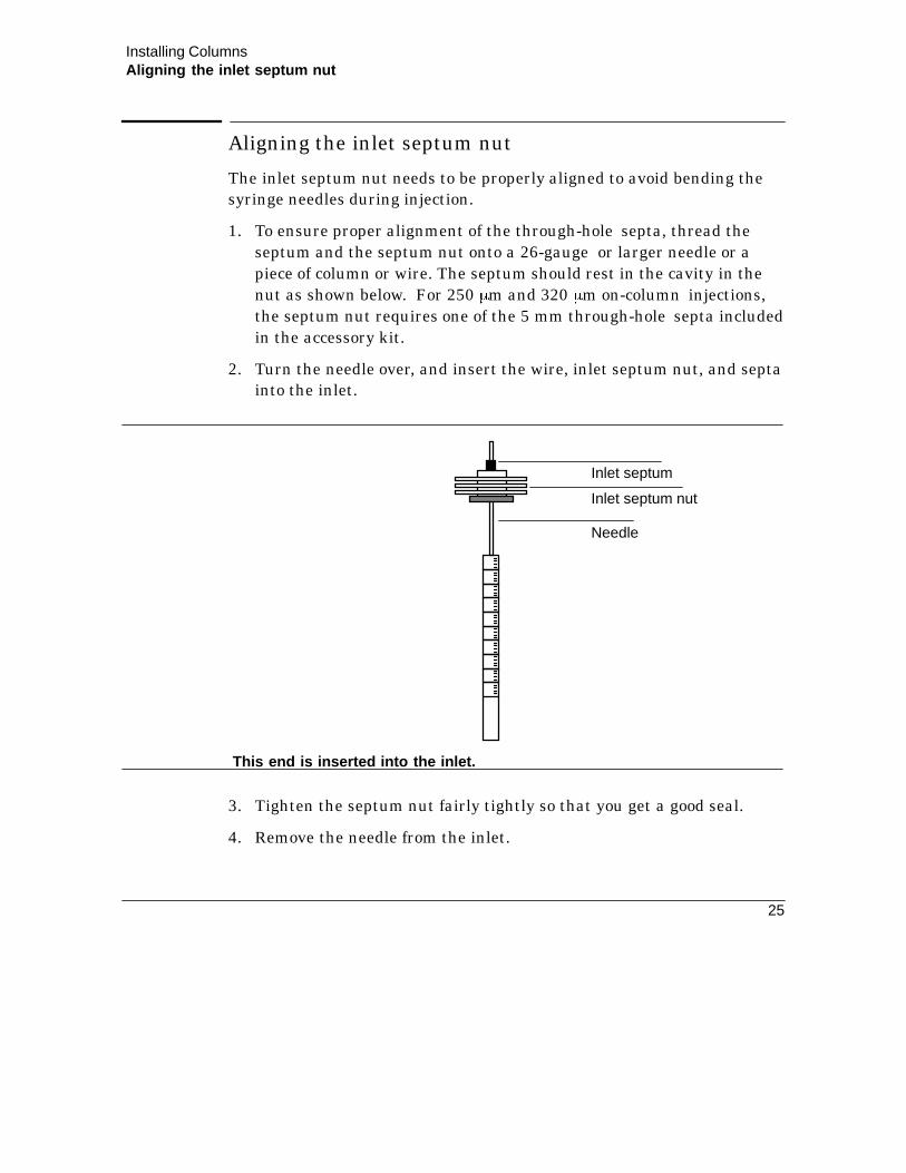
Aligning the inlet septum nut
The inlet septum nut needs to be properly aligned to avoid bending thesyringe needles during injection.
1. To ensure proper alignment of the through-hole septa, thread theseptum and the septum nut onto a 26-gauge or larger needle or apiece of column or wire. The septum should rest in the cavity in thenut as shown below. For 250 mm and 320 mm on-column injections,the septum nut requires one of the 5 mm through-hole septa includedin the accessory kit.
2. Turn the needle over, and insert the wire, inlet septum nut, and septainto the inlet.
Inlet septum nut
Inlet septum
Needle
This end is inserted into the inlet.
3. Tighten the septum nut fairly tightly so that you get a good seal.
4. Remove the needle from the inlet.

Installing ColumnsInstalling the needle into the syringe barrel for automatic injection
26
Installing the needle into the syringe barrel forautomatic injection
The stainless steel needles used for 250 mm and 320 mm injections mustbe inserted into a glass syringe barrel before they can be used in the HP7673 Automatic Sampler.
1. Unscrew the syringe barrel cap, and remove the spring.
2. Select the correct size needle for the column you plan to use, andmake sure the needle has a Teflon disk. If the syringe barrel does nothave the Teflon disk, use the instructions in the syringe box to wrapthe needle yourself.
Needle
Spring
Cap
Teflon disk
Syringe barrel
3. Slide the spring and the cap down over the needle.
4. Insert the needle into the syringe barrel.
5. Screw the cap back on the syringe barrel.
Caution Do not operate the injector without a syringe in place because thesyringe latch may interfere with the motor if it is allowed to swingfreely.

Installing ColumnsInstalling a fused silica capillary column for automatic injection
27
Installing a fused silica capillary column for automaticinjection
Column connections will be more successful if you prepare the columnsproperly. If you have not prepared your column, use the instructionsbelow to do so now.
1. Install a column nut and ferrule on the end of the column.
2. Cut off the column end with a square cut according to the illustrationbelow.
1. Score the column with a carbide knife.
2. Support opposite score mark on knife edge. 3. Press to break.
3. Wipe the column end with methanol to remove fingerprints and dust.
4. Insert the column into the inlet base until it cannot go further.
Flying glass particles can cause eye injuries. Always wear safetyglasses when cutting fused silica columns.
WARNING
5. Finger tighten the column nut, making sure the column remainsagainst the insert.
6. Use a wrench to tighten the column nut an additional 1/4-turn.
7. Verify the column installation by manually pushing your syringe intothe inlet. There should be a gap of 3 mm or less between the septumnut and the syringe barrel.

Installing ColumnsInstalling a fused silica capillary column for automatic injection
28
If there is more than 3 mm between the syringe barrel and septum nut,your needle is not reaching the column, and you will not be able toautomate injection onto 250 mm and 320 mm columns.
Septumnut
Syringe
3 mm or less

Installing ColumnsChecking for column installation problems
29
Checking for column installation problems
Using the right ferrules
Ferrules that are the wrong size or are improperly prepared cause leaksand contamination. Here are some hints to avoid problems:
C Graphite-containing ferrules should be baked at 250-300 ^C for30 minutes before use because graphite is a good absorbent fororganic compounds present in the atmosphere. Leave a petri dish ofassorted ferrules in the GC oven to ensure a clean supply.
The ferrule should slide easily on the column, but not fall off under itsown weight. In this case, no more than 1/4-turn from finger tight isrequired to make a good seal.
If the column od is significantly smaller than the ferrule insidediameter, the column nut will have to be tightened enough tocompress the ferrule around the column. This is usually not a problemwith easily deformed graphite ferrules. Harder ferrules may requireso much torque that the inlet fitting may be bent, or the nut may bebroken. In addition, the ferrule may split and yield a leak. With hardferrules, it is better to start with an undersize hole and drill it to fitthe column.
C Vespel ferrules can be more leaktight than graphite, but have alower temperature limit. They should be retightened after a fewtemperature cycles to ensure a good seal.
Be sure to use the correct ferrule for the size column you are using.

This page intentionally left blank.

4
Setting InletPressure
32
Setting Inlet Pressure
Your cool on-column inlet is equipped with either manual pressurecontrol or electronic pressure control. Read Selecting the best inletpressure in this section, and then go to the instructions for either manualor electronic pressure control, depending on your unit.
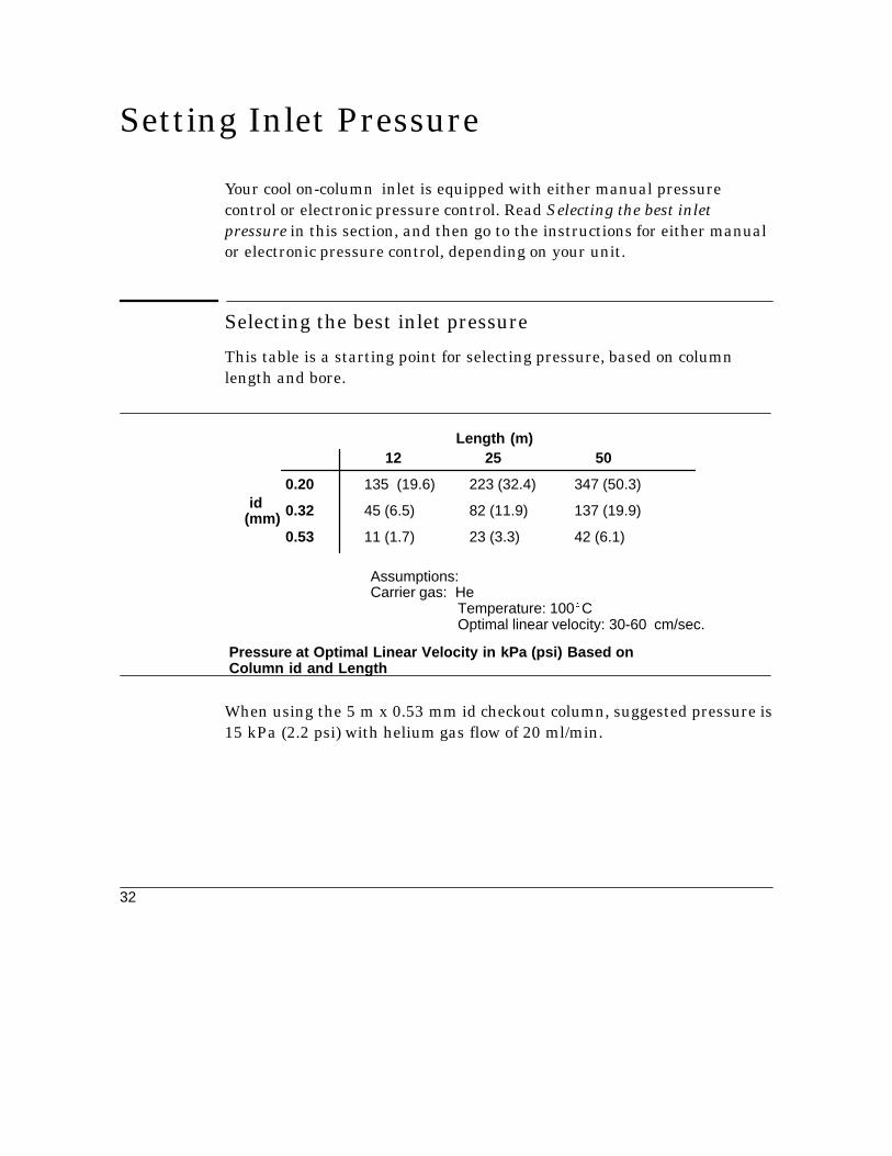
Selecting the best inlet pressure
This table is a starting point for selecting pressure, based on columnlength and bore.
Pressure at Optimal Linear Velocity in kPa (psi) Based onColumn id and Length
Length (m)
id(mm)
12 25 50
0.20 135 (19.6) 223 (32.4) 347 (50.3)
0.32 45 (6.5) 82 (11.9) 137 (19.9)
0.53 11 (1.7) 23 (3.3) 42 (6.1)
Assumptions:Carrier gas: He
Temperature: 100^COptimal linear velocity: 30-60 cm/sec.
When using the 5 m x 0.53 mm id checkout column, suggested pressure is15 kPa (2.2 psi) with helium gas flow of 20 ml/min.

Setting Inlet PressureSelecting the best inlet pressure
33
Choosing pressure for a desired linear velocity
Linear velocity through the column is measured by injecting a samplecontaining an unretained component (typically CH3).
The observed retention time for the unretained component is compared toan expected retention time (tr) calculated from the desired linear flowvelocity (¿) and the length of the column:
t (in min) = 1.67 }Column length (m)
Linear flow velocity (cm/sec)r expected
With repeated injection of the unretained component, adjust the pressureas necessary to obtain the expected retention time for the desired linearvelocity.
To verify flow rate through the column:
1. Turn off detector gases.
2. Measure flow using a bubble flow meter connected at the detectorexhaust vent.
Checking vent flow rate
The septum purge vent is not adjustable, but you should check the flow.Do not cap off the flow from the purge vent.
Carrier Gas Type
H2 12 + 3 ml/min
He 12 + 3 ml/min
N2 12 + 3 ml/min
Ar - Me 12 + 3 ml/min
Approximate Flow
Hydrogen gas is flammable. If you use hydrogen carrier gas, eithervent the purge flow appropriately or add a needle valve restrictor at thevent fitting and adjust the flow down.
WARNING

Setting Inlet PressureSetting inlet pressure using electronic pressure control
34
Safety shutdown
Programmable cool on-column inlets that are equipped with electronicpressure control have a safety shutdown feature to prevent gas leaksfrom creating a safety hazard. If the system cannot reach a pressuresetpoint, the system beeps. After about two minutes, the beeping stopsand the following message appears on the display:
EPPB: SAFETY SHUTDOWN
ACTUAL SETPOINT
The system will shut down by turning off all electronic pressure andheated zones and locking the keyboard.
See the Maintanence and troubleshooting section in this chapter for moreinformation about safety shutdown.
Note: These safety shutdown procedures apply to EPC boards with amainboard ROM part number HP 05890-80310 or higher.
Setting inlet pressure using electronic pressure control
If your GC is equipped with electronic pressure control, you can setconstant pressure or create a pressure program with multiple ramps.
Before you start
1. Be sure carrier source pressure is at least 138 kPa (20 psi) greaterthan the maximum desired inlet pressure.
2. Select the pressure units you would like to use.To change the units, press gold 1 ENTER , and then select
1 = psi,2 = bar, or3 = kPa.
3. From the keyboard, set the pressure.
Set the oven and heated zone temperatures. Be sure the detector isturned on, and its output signal is assigned to the correct channel.

Setting Inlet PressureSetting inlet pressure using electronic pressure control
35
Zeroing pressure
An inlet with electronic pressure control is zeroed when it is shipped.However, you should check this periodically. To zero the pressure, press:
1. gold 0 ENTER Set inlet B pressure to 0.0.INJ B PRES . 0
Allow enough time for the column to completely depressurize.Remove the septa retainer or disconnect the source pressure todepressurze the column more quickly.
2. To zero channel B, press gold ENTER3 value ENTER
where value is the zero offset value shown on the GC display labelled�actual".
3. gold 0 ENTER Set inlet B pressure to 0.0.INJ B PRES . 0
Allow enough time for the column to completely depressurize.Remove the septa retainer or disconnect the source pressure todepressurze the column more quickly.
4. To zero channel A, set inlet A pressure to 0.0, then press
gold ENTER2 value ENTER
where value is the zero offset value shown on the GC display labelled�actual".
Setting constant pressure
Follow the example below to set Injector B pressure to 10 psi.
EPP B 10.0 10.0
ACTUAL SETPOINT
The GC display looks like this.
gold 1 0 ENTER Set inlet B pressure to 10 psi.INJ B PRES
INIT TIME ENTER6 Set initial time to 650 (max).5 0

Setting Inlet PressureSetting inlet pressure using electronic pressure control
36
Note: If the initial time is less than the total run time, the inlet Bpressure will change because it is being controlled by the constant flowmode. Turn off the flow control option to avoid having the pressurechange during the run. To do this, press the following keys until thedisplay looks like the one below:
EPP B CONST FLOW OFF
ACTUAL SETPOINT
The GC display looks like this.
gold FLOW PARAM ENTEROFF
Setting pressure programs (1 Ramp)
This example shows how to start with Injector B pressure at 10 psi for 1minute, then ramp at 5 psi/min to 20 psi, and remain there for 2 minutes.
gold INJ B PRES INIT VALUE 0 ENTER1
INIT TIME ENTER1
RATE 5 ENTER
FINAL VALUE 0 ENTER2
FINAL TIME ENTER2
Set Injector B initial pres-sure at 10 psi.
Set initial time at 1 minute.
Set ramp at 5 psi/min.
Set final pressure at 20 psi.
Set final time at 2 minutes.
Note: The oven program determines the run time of the analysis. If theinlet pressure program is shorter than the oven temperature program,the inlet pressure will go into the constant flow mode for the remainder ofthe run. To prevent this, set the pressure program longer than the oventemperature program.

Setting Inlet PressureSetting inlet pressure using electronic pressure control
37
Setting pressure programs (2 and 3 Ramps)
To add a second and third ramp to the above pressure program, press thefollowing keys after you enter the previous example:
RATE ENTER
FINAL VALUE ENTER2
FINAL TIME ENTER2
Set the second ramp at 2 psi/min.
Set the second final pressure at 26 psi.
Set the second final time at 2 minutes.
A
2
6
A
RATE ENTER
FINAL VALUE ENTER
FINAL TIME ENTER5
4
3
Set the third ramp at 4 psi/min.
Set the third final pressure at 30 psi.
Set the third final time at 5 minutes.
B 0
B
A
B
Checking the pressure program
Display the pressure program by pressing any pressure program key,followed by ENTER . Successively press ENTER to scroll through theprogram.
Note: The oven program determines the run time of the analysis. If theinlet pressure program is shorter than the oven temperature program,the inlet pressure will go into the constant flow mode for the remainder ofthe run. To prevent a pressure program from going into constant flowmode, be sure to set the pressure program longer than the oventemperature program.

Setting Inlet PressureUsing the constant mass flow modes
38
Using the constant mass flow modes
If your system is equipped with electronic pressure control, you canprogram the inlet to maintain constant mass flow. To use the constantmass flow modes:
1. Select the gas type.
FLOW PARAM Scroll to select gas type.
EPP B He [1]
ACTUAL SETPOINT
The GC display now looks like this.Press1= Helium, 2 = Nitrogen, 3 = Hydro-gen,4 = Argon/Methane.
gold FLOW PARAM
2. Press FLOW PARAM again until you see the constant flow display.
EPP B CONST FLOW OFFACTUAL SETPOINT
3. Select the option you wish to use.
OFF = constant flow mode off.
ON = constant flow mode on. You set pressure at oven initialtemperature after turning on the constant flow feature.
Turning off constant flow
When you select OFF , you turn off the constant flow mode. You mustselect OFF if you wish to create independent pressure programs.
Turning on constant flow—you set initial pressure, and the GCmaintains initial flow
When you select ON , you turn on the constant flow mode. You can setan initial pressure at oven initial temperature as follows:
ENTER Set starting pressure to give a constant flow.gold INJ B PRES 1 0

Setting Inlet PressureSetting mass flow rate
39
The GC will then maintain the initial flow throughout the run byautomatically adjusting pressure.
Note: Make sure the oven is equilibrated to initial temperature when theinitial pressure is set; an incorrect flow will result if initial pressure is setbefore initial oven temperature is reached.
Constant flow hint
You can check the flow through the column by turning off the detectorgases and measuring the flow using a bubble flow meter and the GCstopwatch feature. Check the Operating Manual for more details.
Setting mass flow rate
If your system is equipped with electronic pressure control, you can setmass flow rate. This flow control capability is accomplished through theelectronic pressure control function.
For example, when a constant pressure is set, mass flow is displayed(monitoring mass flow). Entering a new mass flow value willautomatically set a new constant pressure to obtain the flow valueentered.
Note: Before setting mass flow, the correct column parameters (columnlength, column diameter, and gas type) must be entered.
Follow the example below to set Injector B flow to 10 ml/min.
1. Select the gas type.
FLOW PARAM Scroll to select gas type.
EPP B He [1]
ACTUAL SETPOINT
The GC display now looks like this.Press1 = Helium, 2 = Nitrogen, 3 = Hydro-gen,4 = Argon/Methane.
gold FLOW PARAM

Setting Inlet PressureSetting mass flow rate
40
2. Enter the column diameter.
Press FLOW PARAM again until you see the column diameter (id)display.
ACTUAL SETPOINT
The GC display looks like this.B: Column Dia .XXXmm
The column diameter must be entered in microns (i.e., 200 mm,530 mm).
5 ENTER Sets the column diameter to 0.530 mm.03
3. Enter the column length.
Press FLOW PARAM again until you see the column length display.
B: Column Len XX.XXM
ACTUAL SETPOINT
The GC display looks like this.
Column length must be entered in meters. If exact column length isunknown, refer to Determining corrected column length.
2 ENTER Sets the column length to 25 meters.5
4. Set the column B desired flow rate.
Press CLEAR FLOW until you see the mass flow control display.
COLUMN B 10.0 Ml/MinACTUAL SETPOINT
ENTER Sets inlet B flow to 10 ml/min.1 0
The GC display looks like this.
Note: Inlet B pressure will change to a value needed to produce 10ml/min.

Setting Inlet PressureDetermining the corrected column length
41
Determining the corrected column length
When you want to set or display mass column flow, you must determine acorrected length and diameter for an equivalent open tubular column.
1. Press gold FLOW PARAM FLOW PARAM until you see the columndiameter display.
Set column diameter to its nominal inner diameter value (100 mm� 200mm� 530 mm� etc.). For a packed column, enter 530 mm.
2. Press FLOW PARAM until you see the column length display.
Set column length to its nominal length in meters.
3. Select the gas type.
FLOW PARAM Scroll to select gas type.
EPP B He [1]
ACTUAL SETPOINTThe GC display now looks like this. Press1= Helium, 2 = Nitrogen, 3 = Hydrogen,4 = Argon/Methane.
gold FLOW PARAMPress
4. Press CLEAR FLOW FLOW until the display reads:
COLUMN B 97.5 Cm/Sec
ACTUAL SETPOINT
This is the computed average linear velocity ( u ) for the estimatedlength column (10 m) at the given temperature.
5. Inject an unretained component and determine its retention time inminutes. This is to Actual.
6. Calculate corrected column length as:

Setting Inlet PressureSetting flow programs
42
L corrected ( to Actual }
1.67 ) where:
= corrected column length in meters
= retention time of unretained component in minutes
u = average linear velocity in cm/sec
u
to Ac-
tual
L corrected
=
Enter the value calculated from the above formula as the column lengthin step 3 of Setting mass flow.
Setting flow programs
Flow programs can be set indirectly through pressure programming oncegas type, column diameter, and column length have been entered.
Note: Column length must be entered in meters. If exact column lengthis unknown, or if a packed column is in use, refer to Determiningcorrected column length. This example shows how to obtain pressurevalues necessary to create a pressure program to set column B flow at 4ml/min, then end with 7 ml/min.
This example shows how to obtain pressure values necessary to create apressure program to set column B flow at 4 ml/min, then end with 7ml/min.

Setting Inlet PressureSetting flow programs
43
1. Press until the display reads:
2. Press until the display reads:
3. Press until the display reads:
CLEAR FLOW FLOW
COLUMN B XX.X ml/min
ACTUAL SETPOINT
4 ENTER
COLUMN B 4.0 ml/min
ACTUAL SETPOINT
The display looks like this.
gold
EPP B 10.0 10.0
ACTUAL SETPOINT
The GC display looks like this.This will be injector B pres-sure initialvalue.
The display looks like this.
INJ B PRES
4. Press until the display reads:FLOW FLOW
COLUMN B 4.0 ml/min
ACTUAL SETPOINT
The display looks like this.
5. Press until the display reads:
6. Press until the display reads:
ENTER
gold
7
COLUMN B 7.0 ml/min
ACTUAL SETPOINT
The display looks like this.
EPP B 14.3 14.3
ACTUAL SETPOINT
The GC display looks like this.This will be injector B pres-sure finalvalue.
INJ B PRES
Use the pressure values obtained from this procedure when you set apressure program. Initial time, ramp rate, and final time are entered aspart of setting the pressure program (see Setting pressure programs).

Setting Inlet PressureSetting average linear velocity
44
Setting average linear velocity
If your system is equipped with electronic pressure control, you can setaverage linear velocity. Like mass flow control, the average linearvelocity capability is accomplished through the electronic pressure controlfunction.
For example, when a constant pressure is set, average linear velocity isdisplayed (while you are monitoring average linear velocity). Entering anew average linear velocity value will automatically set a new constantpressure (and flow rate) to obtain the velocity value entered.
Note: Before setting average linear velocity, the correct columnparameters (column length, column diameter, and gas type) must beentered.
To set average linear velocity, perform steps 1 through 3 of Setting massflow. Then follow the example below to set the average linear velocity to100 cm/sec.
1. Set the column B desired average linear velocity.
Press CLEAR FLOW FLOW until the display reads:
ENTER Set inlet B linear velocity to 100 cm/sec.1 0
COLUMN B 97.5 Cm/Sec
ACTUAL SETPOINT
The GC display looks like this.
0Press
COLUMN B 100.0 Cm/SecACTUAL SETPOINT
The GC display looks like this.
Note: The pressure and flow for Inlet B will change to a value needed toproduce 100 cm/sec.

Setting Inlet PressureUsing vacuum compensation mode
45
Using vacuum compensation mode
Vacuum compensation should be used anytime a mass spectrometer isused, to allow column outlet pressure to be at vacuum conditions. Withvacuum compensation and constant flow on, a constant mass flow isdelivered to the mass spectrometer throughout a temperatureprogrammed run. This results in a constant mass spectrometerionization current level and a 15 to 30% shorter run time.
1. Turn on vacuum compensation:
Press gold FLOW PARAM FLOW PARAM until you see the columncompensation display.
ACTUAL SETPOINT
The GC display looks like this.EPP B VAC COMP OFF
To turn on column compensation, press ON .
To turn off column compensation, press OFF .
After you turn on the vacuum compensation feature, you enter thedesired pressure setting.
Note: HP 5890 Series II GC instruments with electronic pressure controlthat were built before July 1, 1990 will display the message change EPCROM. When this occurs, contact Hewlett-Packard to get an updatedROM.

Setting Inlet PressureSetting pressure using manual control
46
Setting pressure using manual control
If your GC is equipped with manual pressure control, follow theseinstructions to set pressure.
1. Set oven and heated zone temperatures. Be sure the detector isturned on, and the output signal is assigned to the correct channel.
Pressuregauge
Pressureregulator
Septumpurge vent
Flow Panel for Manual Pressure Control
2. Be sure the carrier source pressure is at least 138 kPa (20 psi) greaterthan the selected inlet pressure.
3. Select the inlet pressure using the pressure regulator.

5
Setting InletTemperature

48
Setting Inlet Temperature
Guidelines for selecting inlet temperature
1. Determine the oven temperature program that gives you goodcomponent separation. The starting inlet temperature is usuallysimilar to the starting oven temperature, which is at or below theboiling point of the solvent.
2. Determine the total time of the run.
3. To save time between runs, set the inlet temperature program timeshorter than the total time of the run. This way, the inlet will beginthe cooling process earlier.
4. For best retention time reproducibility, use an oven equilibrium timeof about 3 minutes (1 minute if cryogenic cooling is used).
Setting the inlet temperature to follow the oventemperature (oven track)
The oven track feature sets the inlet temperature 3^C higher than theoven at all times to optimize repeatability. Oven track is on when youreceive your GC from the factory. To turn on oven track:
gold OVEN TRACK ON Turn on the oven trackoption.
INJ A Oven Track ON
ACTUAL SETPOINT
The GC display looks likethis.

Setting Inlet TemperatureCreating an independent inlet temperature program
49
Creating an independent inlet temperature program
This example shows how to start with Injector B temperature at 60^C for1 minute, then ramp at 20^C/min to 100^C, and remain there for 2.2minutes.
INJ B TEMP INIT VALUE 6 0 ENTER
INIT TIME ENTER
RATE 2
1
0 ENTER
FINAL TIME 2 . 2 ENTER
Set initial inlet temperature.
Set initial time.
Set initial rate.
Set final time.
FINAL VALUE 1 0 0 ENTER Set final temperature.
INJ B TEMP INIT VALUE ENTER ENTER Scroll through inlet program.
To optimize repeatability when creating inlet temperature programs, besure that the inlet temperature is always at least 3^ higher than the oventemperature. You do this by turning on the oven track mode.
If the message INJ B Oven Track On appears on the display, pressOFF to disable the oven temperature tracking. You can now program the
inlet temperature independently of the oven temperature.
Using cryogenic oven cooling
Oven temperature may be controlled below ambient when a cryogenicvalve is present. Cryogenic control setpoints are described in thefollowing table:

Setting Inlet TemperatureUsing cryogenic oven cooling
50
CRYO BLAST ON
CRYO ON
CRYO BLAST OFF
CRYO OFF
Enables subambient control of the oven.
AMBIENT Sets optimal temperature control for efficient use ofcryogenic fluid. The default temperature setting is25^C.
Enables very fast cooldown time after a run.
Disables very fast cooling of the oven.
Disables subambient cooling of the oven; the defaultstate for the cryogenic valve is off.
CRYO FAULT ON/OFF
CRYO TIMEOUT XXX MIN
A fault occurs when the oven does not reach settemperature after 17 minutes of continuous cryooperation. The oven turns off, and the messageWARN:OVEN SHUT OFF is displayed. Turning offCryo Fault will disable this feature.
A cryo timeout occurs when a run does not start withina specified time (10 to 120 minutes) after the ovenequilibrates. Turning off Cryo Timeout will disable thisfeature. The default is ON for 30 minutes.
Cryogenic Control Setpoint Description
When the cryogenic valve is turned on, it operates automatically to obtainan oven temperature when there is demand for coolant to be supplied tothe oven.
When cryogenic cooling is not needed, cryogenic valve operation must beturned off. If this is not done, proper oven temperature control may notbe possible, particularly at temperatures near ambient.
The Cryo Blast feature can operate together with or independently ofCryo On/Off. Cryo Blast cools the oven faster after a run than it wouldunder normal cryogenic operation. This allows the HP 5890 GC to beready for the next run earlier than it would without Cryo Blast on. Thisfeature is useful when maximum sample throughput is necessary.

Setting Inlet TemperatureUsing cryogenic oven cooling
51
Successively pressing the CRYO PARAM key scrolls through the cryogenicvalve operation functions. Use the following key sequence to turncryogenic operation or blast on and off:
or
gold
ON OFFOFF
ONCRYO PARAM
To turn Cryo Blast operation on or off, use the following key sequence:
or
gold
ON OFFOFF
ONCRYO PARAM Scroll to Cryo Blast and pressPress
An example key sequence to change the ambient temperature setting to23^C is:
gold CRYO PARAM Scroll to Ambient 2 3 ENTER
You can set the ambient temperature to allow fine tuning of cryogenicoperation. The default setting is 25^C. It does not need to be changed formost applications. For more information about adjusting the ambientcryogenic setting, see the HP 5890 Series II Reference Manual.
The following figure shows the displays associated with disabling andenabling automatic cryogenic valve operation.
CRYO OFF
CRYO ONACTUAL SETPOINT
ACTUAL SETPOINT
CRYO FAULT ONACTUAL SETPOINT
CRYO TIMEOUT 20 MinACTUAL SETPOINT
Automatic CryogenicValve Displays

This page intentionally left blank.

6
Making Injections

54
Making Injections
The HP 5890 Series II cool on-column inlet allows you to inject samplevolumes onto columns that are 250 mm or larger using automatic andmanual injection techniques.
Before the injection
Here is a checklist for injecting into a cool on-column inlet:
C The initial oven temperature should be 25^C below the boiling pointof the solvent.
C The sample injection must be done quickly and smoothly to ensurethat the sample is introduced in liquid form.
C The syringe needle must be withdrawn immediately after injection.
C The sample amount injected, both total volume and componentconcentration, is important; large volumes may cause bandbroadening, particularly for components with boiling pointsapproximately 150^C greater than that of the solvent.
C The recommended sample injection volume is 0.5 ¿l or less for 0.20mm columns. For injections with the HP 7673A automatic samplerthat are less than 1 ¿l , use the nanoliter adapter kit.
C With automatic injection, make sure your syringe and inlet assemblyare aligned correctly, or you may bend your needle.

Making InjectionsCan I automate?
55
Can I automate?
Yes, the special considerations for automatic injection are listed later inthis chapter. The following table shows your choices of needles andautomating ability based on the column used.
Can I do manual Can I do manualCan I do automatic injection with a injection with a stainless
Column id injection? fused silica needle? steel 26-gauge needle?
1. This includes aluminum-coated columns.2. If you use a 0.25 or 0.32 mm precolumn.
0.53 mm1 Yes Yes Yes
0.32 mm Yes Yes Yes, you use 26-32 gauge(HP 5181-1266).
0.25 mm Yes Yes Yes, you use 26-32 gauge(HP 5181-7442).
0.2 mm Yes2 Yes Yes2
Manual injection technique with stainless steel needles
When you are injecting by hand using stainless steel needles, make surethe stainless steel needle guide and disk-type septum are installed. Toperform the injection:
1. Immerse the syringe needle in sample; pump the syringe plunger toexpel air from the barrel and needle.
2. Draw the sample into the syringe.
3. Remove the needle from the sample and draw about 1 ¿l of air intothe syringe.
4. Wipe the needle dry it if it is wet.

Making InjectionsManual injection technique with fused silica needles
56
5. Guide the needle straight into the needle guide, pierce the septum,and insert the needle fully into the inlet.
6. Start the run, depress the syringe plunger as quickly as possible, andwithdraw the needle from the inlet.
Note: These steps should be done smoothly, with minimal delay.
Manual injection technique with fused silica needlesNote: When injecting with fused silica needles, be sure the initialpressure is less than 30 psi. Higher pressures will make needle insertiondifficult.
When fused silica needles are required for injection onto 320 ¿ andsmaller diameter columns, follow these steps for injection:
1. Immerse the syringe needle in sample and pump the syringe plungerto expel air from the barrel and needle.
2. Draw the sample into the syringe. Allow enough time for fluids topass through the small bore of the needle.
3. Remove the needle from the sample and draw about 1 ¿l of air intothe syringe. Wipe the needle with a tissue wetted with solvent.
4. Press the needle guide fully down to open the duckbill.
The inlet needle guide may be hot! Use a pencil to depress the needleguide.
WARNING
5. Hold the needle guide down for about 3 seconds to depressurize thecolumn. This prevents loss of sample due to backflow of carrier gas.When you do this with an electronic pressure controlled system, it willstart to beep while the column is depressurised. The beeps will stopafter the system repressurises.
6. While holding the needle guide down, guide the needle straight intothe needle guide and fully insert it into the inlet.
Hint: If the needle does not go in all the way, try rotating the syringeand slightly releasing pressure on the needle guide.

Making InjectionsReplacing the fused silica syringe needle
57
7. Once the needle is fully inserted, release the needle guide. Allow 1 to2 seconds for backpressure on the duckbill to seal it around theinserted needle.
8. Start the run, depress the syringe plunger as quickly as possible, andwithdraw the needle from the inlet.
Replacing the fused silica syringe needle
Needle
Ferrule sleeve
Teflon ferrule
1. If you are cutting replacement needles directly from fused silicacolumn material:
a. Column material for making needles must have an od smallerthan both the id of the on-column inlet (0.23 mm) and the id of theinstalled column.
b. Column material must be washed free of active stationary phase.
c. Score the column material about 1/4-inch from its end. Break offthe end and discard. Then measure, score, and break off a 115+ 5 mm length to use as the syringe needle.

Making InjectionsReplacing the fused silica syringe needle
58
2. Hold the syringe vertically, and insert the fused silica needle so it isvisible inside the syringe barrel. If the fused silica needle cannot beinserted into the syringe barrel, the Teflon ferrule may be blocked.You may need to replace the ferrule.
3. When the needle is inserted, tighten the retaining nut to firm fingertightness. Pull the needle gently to be sure the Teflon ferrule hasformed a tight seal with the needle. Tighten the retaining nut further,if necessary.
4. Loosen the retaining nut just enough so the needle is again free.Depress the syringe plunger slowly until it pushes the needle to theend of the barrel, then tighten the retaining nut to firm fingertightness.
5. Use a suitable solvent to rinse the syringe and check for leaks orblocks.
Leaks (inability to eliminate air bubbles) may be fixed by furthertightening the retaining nut. Blocks (or serious leaks) requirerepeating this procedure.
Note: The Teflon ferrule may lose its seal in time. If so, first retightenthe retaining nut, and if the seal still leaks, install a new Teflon ferruleand needle.

Making InjectionsReplacing the universal syringe needle
59
Replacing the universal syringe needle
The stainless steel needles used for 250 mm and 320 mm injections mustbe inserted into a glass syringe barrel before they can be used in the HP7673 Automatic Sampler.
To insert a needle into a syringe barrel, follow the procedure below:
1. Unscrew the syringe barrel cap and remove the spring.
2. Select the correct size needle for the column you plan to use, andmake sure the needle has Teflon disk, as shown in the picture below.If the syringe barrel does not have the Teflon disk, use theinstructions in the syringe box to wrap the needle yourself.
3. Slide the spring and the cap down over the needle.
4. Insert the needle into the syringe barrel.
5. Screw the cap back on the syringe barrel.
Needle
Spring
Cap
Teflon disk
Syringe barrel

Making InjectionsAutomatic injection considerations
60
Automatic injection considerations
Syringe needles can be made of stainless steel (size 26 gauge or tapered26-23 gauge) and made from fused silica (size 530 mM, 320 mm, or 250mm). To operate using 250 mM and 320 mM needles, proceed to the nextpage.
When you are performing analyses using an automatic sampler, you mustuse the disk type septum for 530 mm and larger needles and thethrough-hole septa for smaller needles. In addition, consider thefollowing:
C For HP 18593Binjector modules, remove the needle guide top fromthe septum nut base assembly. Save the needle guide top to realignthe bracket.
C For HP 18593Ainjector modules, leave the needle guide top on theseptum nut base assembly. The cup-shaped top is part of the injectormounting scheme.
Septum nutbaseassembly
Needleguide top

Making InjectionsAutomated injection technique
61
Automated injection technique
You can automatically inject into 250 mm, 320 mm, 530 mm columns usingthe on-column inlet However, be sure to align the needle, inlet, andcolumn to ensure the best performance.
Use this checklist to make sure you are ready to inject using the HP 7673Automatic Sampler. For complete instructions on how to operate andtroubleshoot the automatic sampler, see the HP 7673 Automatic SamplerManual.
i The sample vials are half full.
i The vial cap is centered, is not wrinkled, and the septum is flati The sample inserts and vials match the run parameters
i The syringe is the correct design and size for your application.i The plunger carrier screw is tight.i The needle is aligned with the septum retainer nut.
i You have installed the correct septum type.i The septum has been used for fewer than 200 injections.
i The injector run parameters are set correctlyF Injection mode matches type of inlet.F Number of injections per vial is less than 5.
i Each solvent bottle contains 4.5 ml of fresh solvent.i Waste bottle is clean and empty.i You are using 2 waste bottles with the tray.i The number of solvent bottles is limited to number of sample vials.
HP3396

Making InjectionsPerforming automated injection onto 250 µm and 320µm columns
Performing automated injection onto 250 µm and 320 µmcolumns
This section lists the proper procedures for changing, aligning, andinstalling the needle support assembly to adapt from 530 µm injection to250 µm or 320 µm injections. To inject onto 250 µm or 320 µm columns,you first change the needle support assembly.
Removing the 530 µm needle support assembly
Plunger carrier
Plunger screw
Flange guide
Syringe latchSyringe clip
II
I
Slide
62

Making InjectionsPerforming automated injection onto 250 µm and 320µm columns
1.
2.
3.
4.
5.
Lay the injector module on its back on a flat surface, and open theinjector door.
Loosen the plunger screw and slide the loop of the plunger carrier upas far as it will go.
Swing the syringe latch counterclockwise to unlock the syringe.
With your finger under the upper portion of the syringe barrel (justabove the syringe latch), pull the syringe up and gently remove it.
With your finger under the brass fitting of the 530pm needle supportassembly, pull up gently to release and remove the assembly.

Making InjectionsPerforming automated injection onto 250 µm and 320µm columns
Installing the 250 µm and 320µm needle support assembly
1.
2.
3.
Holding the new needle support assembly in your right hand, push thebearing down the shaft of the assembly about 3 inches.
Insert the upper end of the rod into the black plastic guide to the rightof the plunger carrier loop.
Align the bearing on the needle support assembly with the plasticbearing clip to the right of the syringe latch.
Guide-
Tracks
Slide
64

Making InjectionsPerforming automated injection onto 250 µm and 320 µm columns
4. Push the assembly down into place. Make sure the slide lies flat on thetracks of the syringe carriage so that it glides up and down as shown inthe illustration below.

Making InjectionsInstalling the syringe into the needle support assembly
66
Installing the syringe into the needle support assembly
When a syringe is worn, replace it with a new one using the followingsteps:
1. If you have removed the injector module to replace the needle supportassembly, place the module back on the HP 5890 Series II GC oven oron a parking post if you have one.
2. Open the injector door.
3. Pass the syringe needle through the hole of the small, needle guide inthe needle support foot.
Needle guide
4. Align the flange with the flange guide and syringe clip, and gentlypress the syringe into place, keeping the needle in the hole of theneedle guide. Be careful not to bend the needle during this step.
5. Close the syringe latch by swinging it clockwise.

Making InjectionsInstalling the syringe into the needle support assembly
67
Flange
Needle support foot
Syringe clip
Plunger carrier
Syringe latch
Flange guide
Caution Do not operate the injector without a syringe in place because thesyringe latch may interfere with the motor if it is allowed to swingfreely.
6. Move the plunger loop down, and tighten the plunger screw.
7. Move the plunger loop up and down to make sure the plunger ismoving with the carrier.
8. Make sure the needle is aligned with the needle guide in the foot bymoving the slide up and down. The needle should slide smoothly inthe needle guide.
Caution Failure to use the correct size on-column syringe when injecting intoan on-column inlet could damage the injector, syringe, and column.

This page intentionally left blank.

7
Maintenance andTroubleshooting

70
Maintenance and Troubleshooting
This section lists procedures to keep your inlet functioning properly,including:
C Cleaning and care
C Pressure and temperature control problems
C Safety shutdown and alarm relay
C Septum problems
C Syringe problems
C Sampler vial cap septum problems
C FID flameout problems
C Proper configuration
C Peak broadening and split peaks
C Useful tools
Cleaning and care
Most laboratories have airborne lint and dust that accumulates on theneedle guide and can be carried into the inlet or column on the syringeneedle. Particulate matter in the inlet interferes with easy passage of thesyringe needle. If dirt enters the column, it can alter the chromatography.
Clean the stainless steel needle guide, spring, and insert by sonication for1 minute in aqueous detergent, then in distilled water. Rinse withmethanol, and air dry. Check the insert for cleanliness with a magnifier.
Clean the fused silica needle guide by forcing methanol through theneedle with a squeeze bottle.

Maintenance and TroubleshootingTroubleshooting automatic and manual injections
71
Troubleshooting automatic and manual injections
If you have checked these possible causes and still have a problem, callyour nearest Hewlett-Packard Service office.
Symptom Possible Cause Corrective or Preventive Action
Not enough Septum leaks or is missing. Check system for leaks.pressure (safetyshutdown activated). Column is broken.
Column ferrule seal leaks.Gas supply is off.Supply pressure is inadequate.Desired pressure may not beachievable with the column in use.
Pressure goes Configuration is wrong. Check your configuration into 0 or maximum. “Proper Configuration”.
Not Ready light Septum or column connectionflickers (oscillating leaks.pressure). Pressure set higher than the
operating limit.
Not Ready light Configuration is wrong. See “Proper Configuration”.flickers (oscillatingtemperature). Inlet temperature equilibration Increase equilibration time.
time is too short.
Pressure and Configuration is wrong. See “Proper Configuration”.temperatureare not controllable.
Inlet cools down Fan is either not running or Check that the fan is running.very slowly. blowing away from inlet.

Maintenance and TroubleshootingTroubleshooting automatic and manual injections
72
Symptom Possible Cause Corrective or Preventive Action
Bent needle Incorrectly installed needle Check needle support assemblysupport assembly installation.
Defective needle Check each syringe before installationto make sure needle is straight.
Incorrect insert Make sure the insert is the correct sizefor the column and needle you use.Also check that the insert is installedcorrectly.
Overcrimped vial caps See Capping sample vials in theHP 7673 Automatic Sampler Manual forinstructions on crimping vial caps.
Worn or damaged rubber Check the needle guide on the needleneedle guide support foot every time you change the
inlet septum, and replace if necessary.
Incorrect inlet septum Use only a 5-mm septum with athrough-hole.
Poor alignment of inlet Align the inlet septum and septum nutseptum and septum nut according to the instructions provided
in this manual.
Incorrect column Check the internal diameter of theinternal diameter column by using the appropriate
insert.
Closed inlet septum hole Replace the septum.
Poor alignment of the inlet See the HP 5890 Series II Operatingand the automatic injector Manual for alignment instructions.

Maintenance and TroubleshootingTroubleshooting automatic and manual injections
73
Symptom Possible Cause Corrective and Preventive Action
No peaks or Plugged syringe needle Replace the needle, or clean it with wire.unexpectedlysmall peaks
Worn syringe barrel Replace the syringe often, or use a gas-tight syringe. (Under high pressure, thesample is pushed upward through thegap between the plunger and the glassbarrel, and a worn plunger can lead tosample loss.)
Loose removable needle Make sure syringe barrel caps arescrewed on tightly and that the Teflondisk is wrapped tightly.
Incorrectly placed or Check every syringe needle to makemissing Teflon disk on sure the Teflon disk is present andthe syringe needle correctly placed.
Poor precision; Worn syringe barrel Replace the syringe often. (Under highpoor repeatability; pressure, the sample is pushed upwardlarge standard through the gap between the plunger anddeviation the glass barrel, and a worn plunger can
lead to sample loss.)
Loose removable needle Make sure syringe barrel caps arescrewed on tightly and that the Teflondisk is in place.
Widened holes in vial caps Replace vial caps when holes widen andleaks develop. (A sample with a lowboiling point can escape through a holethat has become too large.)
Inlet pressure set too low. Adjust the pressure.
Incorrectly placed or Check every syringe needle to makemissing Teflon disk on sure the Teflon disk is present andthe syringe needle correctly placed.
Maintenance and TroubleshootingSafety shutdown
74
Safety shutdown
Programmable cool on-column inlets that are equipped with electronicpressure control have a safety shutdown feature to prevent gas leaksfrom creating a safety hazard. If the system cannot reach a pressuresetpoint, the system beeps. After about two minutes, the beeping stopsand the following message appears on the display:
EPPB: SAFETY SHUTDOWN
ACTUAL SETPOINT
Also, a relay signal is set that can trigger an alarm.
A safety shutdown can occur under the following conditions:
1. There is a leak in the system (see Pressure and temperature controlproblems). This includes missing septa or columns!
2. The column is not restrictive enough to reach desired pressure (i.e.,530 ¿ columns will not go to 100 psi with available flow).
Note: This may occur during a programmed pressure ramp that is toohigh a pressure.
3. There is insufficient supply pressure.
4. Configuration is set wrong. Check the mode switch on the inletcontroller board (see Proper configuration).
To recover from a safety shutdown, turn the GC power off, then on. Thenreset temperature and pressure zones to desired values. (After safetyshutdown, pressure setpoint is automatically reset to zero.)

Maintenance and TroubleshootingSeptum problems
75
Septum problems
The od and thickness of the disk septa are critical for long life andleak-free operation. If the od is too small and the septum is too thick, theseptum will fail prematurely. A thick septum can bend needles and makeneedle insertion difficult.
If the septum drops easily into the retaining well and falls out when theneedle guide is turned upright, the od is too small. The od should be 5mm, and the septum should fit snugly in the retaining well.
When the needle guide is screwed onto the inlet, resistance will be feltwhen contact is made with the septum. This should occur when the guideis 1/8-or 1/4-turn from bottoming on the inlet body. If contact occurssooner, the septum is too thick. If no resistance is felt, the septum may betoo thin.
Syringe problems
For manual injection with fused silica needles, make sure the needle isclean and free of dust. Wipe with solvent wet tissue, and wipe dry justbefore injection. Use the same solvent used to dissolve the sample. If theneedle should break, replace it. Do not use a needle less than 10 cm long.
For automatic injection, the same cleanliness precautions apply asmentioned earlier. All the areas in the automatic sampler that introducesamples (wash/waste bottles, needle guide) collect dust and should becleaned periodically.
For longer septum life, you can polish the syringe needle with fineabrasive to remove any concentric ridges left from the needle drawingprocess. These are visible when magnified, and, if present, can scrapeseptum particles into the inlet.

Maintenance and TroubleshootingAutomatic sampler vial cap septum problems
76
Automatic sampler vial cap septum problems
Contamination can occur from vial cap septa, particularly if more thanthree injections are made from one vial. Repeated punctures maydislodge septum pieces into the sample. To determine if this is acontamination source, cut a 1- x 2-mm segment from a septum andslurry in a vial with 1 ml of the same solvent used for the sample.Analyze this mixture under the same conditions used for sample analysis.If peaks appear that might interfere with your analysis, try other types ofsepta until you find one compatible with your analysis. A similar test canbe run with the injection port septum if you suspect it to be a source ofcontamination.
Contamination can also occur when small particles are picked up by thesampler syringe and delivered on column. The symptom is sudden onsetof a tailing solvent and early eluting component peaks.
The only solution is to remove enough column to eliminate the particles.The easiest way to find them is to backlight the column with a flashlight.Cover the lens with a tissue to diffuse the light. Move the light along thecolumn until the offending particles are found and cut off enough columnto eliminate them. Use a magnifier if necessary; a single, very smallparticle will cause significant tailing.
FID flameout problems
When using pressure programming with large id columns (i.e., 530 ¿
columns) it is possible to blow out the FID flame if pressure (flow)becomes too high. If this occurs, either lower the pressure ramp or switchto a more restrictive column (longer and/or smaller id).

Maintenance and TroubleshootingPeak broadening and split peaks
77
Peak broadening and split peaks
As a sample is injected on the column at a temperature below the boilingpoint of the solvent, the carrier gas pushes the liquid farther into thecolumn, creating a flooded zone. The solute components are spread overthe length of the flooded zone. This is called band broadening in space.
1. Sample on column at moment of injection
2. Carrier gas pushes liquid solvent to create aflooded zone. The solutes distribute themselvesevenly across this zone, causing band broadening.The flooded zone is made worse when the solvent isless soluble in the stationary phase.
The length of the flooded zone depends on the solubility of the solvent inthe stationary phase. If the solvent is less soluble, the flooded zone will belonger, and peak broadening will be greater.
Further distortion comes from nonuniform distribution of low volatilitycompounds across the solvent band. This gets worse as sample volumeincreases, and column length or diameter decreases.

Maintenance and TroubleshootingPeak broadening and split peaks
78
Possible solutions
1. Check Solubilities. Make sure the polarity of the solvent iscompatible with with polarity of the stationary phase you are using.The length of the flooded zone is affected by the solubility of thesolvent in the stationary phase. If the solvent is less soluble, theflooded zone will be longer, and peak broadening will be greater.
2. Use a Retention Gap (RG). A retention gap is a deactivated,uncoated (or thinly coated) precolumn in series with the analyticalcolumn.
In general, the length of the retention gap required and type ofdeactivation depend on injected volume and solvent polarity. Aworking rule of thumb is to use 0.3-m or 1-m of retention gap per ¿linjected. For a 3 ¿l sample, use a 3-m RG. The RG should be wettedby the solvent, which means it should be deactivated with material oflike polarity. Fused silica tubing is commercially available in a rangeof diameters and deactivations.
Automatic injection requires a 0.53-mm id RG, but the analyticalcolumn can be of smaller id.
3. Optimize the Temperature Program and Inlet. Check the boilingpoints of the solvent and solutes.
4. Use the Right Injection Volume. Know the capacity of the column.Injection volume is important; large volumes may exhibit bandbroadening, particularly for components whose boiling points aremore than 150^C above that of the solvent.

Maintenance and TroubleshootingProper configuration
79
Proper configuration
If the inlet is not working at all, there may be a configuration problem.
1. Turn off the GC power, and remove the side panel of the GC.
2. Check if the switches on the inlet controller board are set for yourconfiguration.
3. Turn on the GC.

Maintenance and TroubleshootingProper configuration
80
Switch setting examples
MODE AIN A0
IN A1
MODE B
IN B0
IN B1
INLET B = Cool On-Column with Electronic Pressure Control
INLET A = Any Non-Electronic Pressure Controlled Inlet
RIGHT
LEFT
LEFT
Left = OpenRight = Closed
RIGHT
RIGHT
RIGHT
This group of switches controls the A posi-tion inlet. If another electronic pressurecontrolled inlet is installed in the A posi-tion, this group of switches must be setaccording to the instructions for that par-ticular inlet.
NOTE
MODE AIN A0
IN A1
MODE B
IN B0
IN B1
INLET B = Any Non-Electronic Pressure Controlled Inlet
INLET A = Cool On-Column with Electronic Pressure Control
RIGHT
LEFT
LEFT
RIGHT
RIGHT
RIGHT
This group of switches controls the B posi-tion inlet. If another electronic pressurecontrolled inlet is installed in the A posi-tion, this group of switches must be setaccording to the instructions for that partic-ular inlet.
NOTELeft = OpenRight = Closed

Maintenance and TroubleshootingProper configuration
81
MODE AIN A0
IN A1
MODE B
IN B0
IN B1
INLET B = Cool On-Column with Electronic Pressure Control
INLET A = Cool On-Column with Electronic Pressure Control
RIGHT
LEFT
LEFT
RIGHT
Left = OpenRight = Closed
LEFT
LEFT

Maintenance and TroubleshootingProper configuration
82
Setting manual pressure control board configuration
IN A0
IN A1
IN B0
IN B1INLET B = Cool On-Column with
Manual Pressure Control
INLET A =Any Other Inlet
RIGHT
LEFT
RIGHT
RIGHT
RIGHT
Left = OpenRight = Closed
IN A0
IN A1
IN B0
IN B1INLET B = Any Other Inlet
INLET A = Cool On-Column withManual Pressure Control
RIGHT
LEFT
RIGHT
RIGHT
Left = OpenRight = Closed
RIGHT
IN A0
IN A1
IN B0
IN B1INLET B = Cool On-Column with
Manual Pressure Control
INLET A = Cool On-Column withManual Pressure Control
RIGHT
LEFT
LEFT
RIGHT
RIGHT
Left = OpenRight = Closed

Maintenance and TroubleshootingUseful tools
83
Useful tools
C Ultrasonic cleaning bath• It is the only effective way to cleansmall parts.
C Tungsten carbide knife• Used for cutting fused silica tubing. Theknife edge can be kept sharp with an inexpensive diamond hone, suchas those used for touching up carbide-tipped saw blades and routertips.
C Drill index (#61-80)• Used for drilling holes in Vespel andGraphite/Vespel ferrules.
C Reamers• Used to ream slightly undersized holes drilled in ferrulesto match column diameter closely.
C 10xmagnifier• Used for examination of column ends and smallhardware.
C Hemostats (curved or straight)• Very handy for manipulating smallparts without losing them or contaminating with fingerprints.
C Fine abrasive paper (emery or 600-grit silicon carbide)• Used forsmoothing rough edges and polishing surfaces.

This page intentionally left blank.

85
Index
250 um injection, 61, 62
320 injection, 61, 62
Aautomated injection
consumables, 15guidelines, 55installing the column, 27installing the syringe, 26, 66vial cap problems, 76
automatic injection, 60
average linear velocity, setting, 44
Bband broadening in space, 77
bent needles, troubleshooting, 72
butt connectors, 17
Ccapillary columns, preparing, 21
cleaning and care, 70
cleaning the system, 70
columnconnecting, 21, 27installation problems, 29installing, 27preparing, 27
column length, corrected, 41
column size, checking the, 22
columnsinstalling, 20sizes of, 20
configuration, 79
configuring the system, 79
constant flow, turning off, 38
constant flow modes, 38
constant pressure, 35
cool on-column, defining, 6
cool on-column features, 7, 8
cryo blast, 50
cryogenic oven cooling, 49
Eelectronic pressure programming, 34
setting constant, 35setting switches, 80
Fferrules, 29
FID flameout, 76
FID flameout problems, 76
flooded zone, 77
flow control modes, 38
flow programs, setting, 42
flow rate, setting, 39

Index
86
Iinjection
automated, 61, 62automatic, 60manual, 55, 56
injections, 54
inlet septum nut, aligning, 25
inlet switches, setting, 80
inlet temperatureprograms, 49setting, 48setting oven track, 48
insert, 6changing, 23cleaning, 70installing, 23selecting the correct, 12
inserts, 22
Llinear velocity, 32, 33
setting, 44
low pressure, 71
Mmaintenance, 70
manual injection, 55
manual pressure control, 46
mass flow rate, setting, 39
Nneedle, replacing the universal syringe, 59
needle guide, 15changing, 13cleaning, 70
needle size, 22
needle support assembly, 62250 um columns, 15320 um columns, 15selecting, 15
needle-to-column size, 22
needlesfused silica, 56replacing fused silica, 57stainless steel, 55
not ready light, 71
Ooven, cryogenic cooling, 49
Ppeak broadening, 77
poor precision, 73
precolumn, using, 16
press-fit connectors, 16
Pressure, Zeroing, 35

Index
87
pressurechoosing best, 32setting, 32setting constant, 35setting manually, 46setting programs, 36setting with electronic pressure
programming, 34too low, 71
pressure gauge, 46
pressure regulator, 46
pressure units, selecting, 34
program, flow, 42
programmed pressure, 36
programmed temperature, 49
purged connectors, 17
Rretention gap, 78
using, 16
Ssafety shutdown, 34
electronic control, 74
selecting pressure units, 34
septum, changing, 13
septum nut, aligning, 25
septum problems, 75
split peaks, 77
syringeautomated injection, 67installing for automated injection, 66replacing the universal, 59
syringe needlealigning, 25installing into the syringe barrel, 26
syringe problems, 75
Ttemperature
guidelines for selecting, 48inlet programs, 49oven track, 48setting, 48
tools, 83
troubleshooting, 70automated injection, 71manual injection, 71septum, 75
Vvacuum compensation, using, 45
vent flow rate, 33
vial cap septum problems, 76