how to - extension media to “bim-enable ipd” spring 2009 ... augi aec edge. contents . spring...
TRANSCRIPT

How to “BIM-Enable IPD”
spring 2009
www.augiaecedge.comwww.autodeskcatalog.com/AECEdge
REVIT CROSS-DISCIPLINE
REVIT ARCHITECTURE
REVIT STRUCTURE
REVIT MEPAUTODESK INS IDERS
PREMIERE ISSUE

Contex Americas, Inc.www.contex.comToll Free: 877-226-6839 (877-2-CONTEX)Phone: +1 (240) 399 5600
The widest selection ofno compromisescanner solutions
From Flatbed to 54”
Fits your Budget
and Work ow
AEC, Technical/CAD,
GIS and Graphics
Archiving, Copying,
and Sharing
User-Friendly
Nextimage Software
High Performance
for the Real World
Superior Product
Quality and Reliability
All of the Above
When we say no compromise scanning and copying, we mean it! We know that requirements vary depending on the type of documents you work with, so we’ve made sure you can nd the right wide format scanning solution to t your business needs. With an impressive product portfolio of 8 Contex HD and 4 SD Series scanners in 19 different con gurations, we are con dent we have the solution you are looking for. Why compromise?
Please contact us at [email protected] or visit our websitewww.contex.com for more information.
60 Days to SaveSpecial
Financing Available

AEC Software(to come)

� www.autodeskcatalog.com/AECEdge spring_2009
AUGI AEC edge
contents features sp
rin
g 2
00
9
18
5 President’s Message
6 editor’s Message
REvIt CRoss-DIsCIPlInE9 How can tHe introduction of business & software systeMs affect your business?
18 iPd Project delivery: autodesk traPelo road
21 a little HelP froM My friends CollaborationbetweenConsultants
24 extending biM design value UsingtheRevitAPI
27 a trainer’s PersPective: KeyRequirementsforaSuccessful BIMImplementation
30 a general contractor’s venture into biM and vdc
REvIt ARCHItECtuRE42 revit in a large firM
AtaleofimplementingRevit
45 getting oriented witH revit’s coordinate systeM
48 key requireMents for a successful biM iMPleMentation
50 a tutorial for line based faMilies
54 revit in HigH scHool MeetTwoProgressiveTeachersandtheir
program
REvIt stRuCtuRE58 growing revit structure
60 integrating analysis PrograMs witH revit structure
62 revit ready - looking back
54
48
33

www.augieaecedge.com �spring_2009
CAD zation (to come)
To be updated

� www.autodeskcatalog.com/AECEdge spring_2009
REvIt MEP66 How to Play nice:
SharingRevitModelsBetweenDisciplines
69 five stePs to success witH revit MeP:TheReality
72 Putting tHe ‘i’ in your biM content: RevitMEPfamiliesthatcapturedesignintent
76 revit MeP iMPleMentation at cta grouP
AStrugglewithPromise
DEPARtMEnts 11 contributed wHite PaPer
AUGIAECEdgefeaturesawhitepaperineachissuethatprovidesinformationaboutanAutodeskproductorotherrelevantrecommendationsrelevanttotheAECindustry.
33 autodesk insiders
36 augi local cHaPter focus - soutH coast revit user grouP (scrug)
39 attorney at large
56 inside track
64 Head’s uP
tab
le o
f co
nte
nts
(co
nt.) AuGI AEC EDGE
www.augiaecedge.comwww.autodeskcatalog.com/aecedge
Publisher karen Popp [email protected]
Editor stephen stafford [email protected]
Contributing Writers david baldacchino, jarrod baumann, bill brown, lay christopher fox, bruce gow, laura Handler, anthony Hauck, jim keller, joel londenberg, Michelle louw, robert Manna, toby Maple, Matt Mason, damon ranieri, jamie richardson, james salmon, elizabeth shulok, david thirlwell, cyril verley & tom weir
Production/Art Director stephanie rohrer 415.255.0390 x13 [email protected]
Traffic Coordinator kali snowden [email protected]
Advertising / Reprint Sales karen Popp 415.255.0390 x19 [email protected]
Extension Media, LLC - Corporate Office
President vince ridley [email protected]
Vice President, Marketing and Product Development karen Murray [email protected]
Vice President, Business Development Melissa sterling [email protected]
Vice President, Sales Embedded Electronics Media Group clair bright
AUGI Board of Directors:
President Mark kiker
Senior Vice President richard binning
Vice President/Secretary bill adam
Treasurer john adams
Members at Large chris lindner steve stafford Peter jamtgaard
Published by:
The AUGI AEC Edge Magazine is published by Extension Media LLC and AUGI. Extension Media LLC and AUGI makes no war-ranty for the use of its products and assumes no responsibility for any errors which may appear in this publication nor does it make a commitment to update the information contained herein. The AUGI AEC Edge Magazine is Copyright ®2009 AUGI. No information in this magazine may be reproduced without expressed written permission from AUGI.
All registered trademarks and trademarks included in this magazine are held by their respective companies. Every attempt was made to include all trademarks and registered trademarks where indicated by their companies.
contents special sections & departments
64

www.augieaecedge.com �spring_2009
President’s Message
theinauguralissueofAUGIAECEdgeisareality.Thebrainchildof the AUGI Board has moved
fromconcepttocompletion.Andboywasitalongtrip.
It all started as a brainstorming ideaI shared amongst the Board membersto see if itwasagoodconcept. After
manydiscussionsandconversations,wedecidedtoshareourideawithotherstoseeiftheythoughtitwasviable.InearlyAugustof2008,IapproachedKarenPoppofExtensionMediatodiscusstheidea.KarenhadhelpedAUGIinthepastbyplacingAUGIads inotherpublications theyproducewithAutodesk. Exten-sionMediawasgraciousenoughtopromoteAUGIforfree.
KarenandIdiscussedthepositiveimpactthattheindustrymightseefromapublicationthatwasfocusedonAECwithaRevitfo-cusedpremiereissue.Thosetalksleadtoanagreementandthatagreementleadtotheproductionofthismagazine.
Duringtheperiodofcontentcreationandsponsorshipgathering,theeconomytookamajorhit.Weallfeltitanditimpactedallofusinsomeway.Thiscausedalongerleadtimeinthefundingprocess,sothemagazineexperiencedmultipledelaysinproduc-tionaswesoughttogetthewordout.
Well– it tookawhile longerthanI imagined,butIamnot inthepublishingindustry.Wearecommunitybuilders.ExtensionMediahasthepublishinggurus.ManythanksgotoKarenforpulling it all together. Her tireless devotion to see this effort
cometofruitionandExtensionMedia’spartnershipwithAUGIhasmadeitpossible.
AUGIAECEdgeisdedicatedtobringingourmemberscurrent,actionable,practicalcontenttothoseinvolvedintheArchitectural,Engineering,ConstructionandOwnersmarketplace.Thecon-tentisopentoallmembers,butwillfocusontheindustriesthatdesign,engineer,constructandmaintainthebuiltenvironment.DesigntoolsrangefromAutoCAD,AutoCADArchitecture,theRevit platforms, 3DS Max and Design, Navisworks, program-mingtoolsandmayevenspilloverintoCivil3D,Map,Inventor,Mayaandothersastheytouchthismarket.Wearenotlimitedtojustsoftware,wemaydiscussmethods,emergingtrends,projectspotlights,CADandBIMManagement,education,trainingandmore. ThisisreallyyourmagazineasmembersofAUGI. Weencourageyoutohelpusdefinewhatyouwanttosee.
Weplanonpublishing4timesannuallysolookformoretocome.Ifthisprovessuccessful,wemaybranchoutintootherindustriesthatourmembershipmayreflectanddesire.
Send me an email with suggestions or comments [email protected]
Thanksandenjoy,
Mark W. KikerAUGIPresident
➲
...the brainchild of the augi board has moved from concept to completion. and boy was it a long trip...

� www.autodeskcatalog.com/AECEdge spring_2009
Editor’s Note
...yes, this issue is focused on revit partly because it is timely to do so ...
thisfirstissueofAUGIAECEdgeisfocusedon, the oft repeated acronym these days,BIM(Building InformationModelling)and
Autodesk’s Revit platform products; Revit Archi-tecture, Structure and MEP. We have articles forwhichaportionarededicatedtoeachoftheproducts
andanotherportionthatoffertheinsight,knowledgeandopinionsofcontractors,consultantsandevenalawyer!
Inadditiontotheseproductfocusedarticleswehavefourdepart-ments:AUGILocalChapterFocus,InsideTrackandHead’sUp.We’llusethesetospotlightaLocalChapterinAUGI,touchoncurrentnews,some inside“scoops”, ifpossible,and list someoftherecentissuespostedatAUGIorAutodesk’s“KnownIssues”knowledge base. In the futurewe hope to include departmentsforNewsBriefsandproduct,hardwareandperipheralequipmentreviews.
An apology!Already?Yes,thisissueisfocusedonRevit;partlybecauseit istimelytodosoandpartlybecausemylifeisconsumedbytheseproductsanditiswhereIcouldreadilydrawontalentedpeopletocontributearticles.AsMarkKikermentionedinhisPresident’sMessage,assumingthisissueprovessuccessful,wehaveeveryin-tentionofexpandingthereachofthispublicationsothatitcanbeusefulandrelevanttoourmembers,andothers,whouseanyofthemanyotherproductsthatAutodeskproduces.
Pleasedon’ttakethisinitialfocusasaslighttowardtheproductyouhappentousetodoyourworkintheAECsector.Andyes,inthisissuewehavetheA&EcoveredbutnoC(Civil).Welookforwardtobeingabletoincludearticlesthatmorefullyrepresentourmembersinterestsinthefuture.
Authors!!Iwanttothankeachoftheauthorswhocontributedtheirworktothisissue.Forsomewritingcomesnaturallyandforothersitis the last thing theywant todo.Fortunately thesepeoplealsohappentoliketo“sharethewealth”,sotospeak.Itisatraitcom-montosomanyofAUGI’smembersandwhatmakesitaspecialorganization.Averyspecialthankyoutoourvolunteerauthors(in alphabetical order): David Baldacchino, Jarrod Baumann,Bill Brown, Christopher Lay-Fox, Bruce Gow, Laura Handler,Anthony Hauck, Jim Keller, Joel Londenberg, Michelle Louw,RobertManna,TobyMaple,MattMason,DamonRanieri,JamieRichardson, JamesSalmon,ElizabethShulok,DavidThirlwell,CyrilVerley,&TomWeir.
Thanks!!I also want to thank Karen Popp and Stephanie Rohrer withExtensionMedia.Thismagazinewouldnotbeavailable toyouwithoutKaren’stirelessefforttosecurefundingandsupportforit.Editingisn’tmyvocationandStephaniemadetheexperienceeasy!Thankyouboth!!
It is my hope that you’ll find the information we’ve providedusefulandthatyou’llsupportAUGI,oursponsorsandadvertis-ers.Consideringtheeconomichardshipmanyarefacinginthisindustryatthistimewecanallusealittlesupport!Ifyouhavequestions/suggestionsorwouldliketoofferyourtalentasanau-thorpleasesendmeanemail:[email protected]
Thanks for reading!
Steve StaffordAUGIAECEdgeEditorMemberAUGIBoardofDirectors2006-08AUGIRevitCommunityForummanager
➲


Autodesk University attendees — pick up your FREE copies of the 2007 editions at the Extension Media Booth #576
or subscribe online at www.autodeskcatalog.com
Three Essential Resourcesfor Design Professionals
Using Autodesk Applications
Visit www.autodeskcatalog.com to stay current on news, product announcements and information on Autodesk-compatible applications. Compare product research and read complete feature articles and case studies.
• Locate vendors, products and
services to get to market faster
• Find off-the-shelf applications that
can save you time
• Discover add-on’s to complement
and extend Autodesk applications
• Quickly connect to Autodesk
authorized training centers (ATCs®)
The Autodesk® Partner Solutions Resource Catalog – North America & Europe Editions – provides valuable information to:
Time-saving answers for design professionals using Autodesk applicationswww.autodeskcatalog.com
Autodesk®
Partner SolutionsResource Catalog Europe 2009
www.autodeskcatalog.com/europe
Purchasing guides for CAD professionals
Diamond Sponsor
Gold SponsorPlatinum Sponsor
HOME | NEWS | RESOURCES | WHITE PAPERS | VIDEOS | BLOGS | BUILDING DESIGN | MEDIA & ENTERTAINMENT | INFASTRUCTURE | MANUFACTURING | PROCESS & POWER
AUTODESK TECH VIDEOS
BLOGS/TWITTERED’s EDIT
Life on the Treadmill How many engineers think of their career as being spent on a treadmill? It is a larger portion than most.y
JOHNS’S JAMWhat does Impinj, Virage and Intel have in common?I read in my local newspaper earlier this week that
MENTOR MAGICCan ASIC I read in my local newspaper earlier this week that Carn-egie-Mellon professor Randy Pausch
Adiitional Videos
KEYWORD RSS | SUBSCRIBE | ADVERTISE | ABOUT US | CONTACT
AUGI | AEC Edge will deliver mission-critical, game changing, industry leading, best practice advice on the AEC industry
Feature articles divided by discipline focus
Q&A
News Briefs
Inside Track
BE FIRST TO KNOW!Order your FREE copy TODAY
FEATURED WHITE PAPERS
Memory Trends Highlight Evolution and RevolutionThe German word Fahrvergnügen directly translated means “the joy of driving”, and anybody who has ever driven a performance car on the German Autobahn knows what I mean... by Kontron
Multi-core Hits EDA Software at Its CoreThe German word Fahrvergnügen directly translated means “the joy of driving”, and anybody who has ever driven a performance car on the German Autobahn knows what I mean... by Kontron
Collaboration ModelsThe German word Fahrvergnügen directly translated means “the joy of driving”, and anybody who has ever driven a performance car on the German Autobahn knows what I mean... by Kontron
More Featured White Papers
TOP STORIES AND NEWS
NYacad Releases SolidStructural v.9.6 for AutoCADSupports history based and direct modeling; available ‘later this year’...
US CAD Releases Styles Template for AutoCAD Civil 3DSupports history based and direct modeling; available ‘later this year’...
Amazon Reduces AutoCAD LT Price to $975Supports history based and direct modeling; available ‘later this year’...
iCADsales.com Releases progeTABLESupports history based and direct modeling; available ‘later this year’...
SYCODE Releases 20 Import/Export Plug-Ins for BricscadSupports history based and direct modeling; available ‘later this year’...
IN THE NEWS
More Announcements
DIGITAL EDITIONS
NORTH AMERICA
HOME | ABOUT US | SUBSCRIBE | ADVERTISE | CONTACT US | PRIVACY STATEMENT
All Materials on this site Copyright © 2008 Extension Media LLC All Right Reserved
CALENDAR OF EVENTS
International Test Conference28 Oct 2008 - Santa Clara Convention Center
EDAC Kaufman Awards
28 Oct 2008 - Santa Clara Convention Center
Mentor User2User
28 Oct 2008 - Santa Clara Convention Center
See Complete List
FEATURED ARTICLES
HP and Autodesk
IMAGIN iT— Beyond Software. A Solutions Provider.
Simulate Camera Defocus with GenArts’ Sapphire Plug-ins
Industrial design company helps make change easier
TurboSquid cornerstone of the exploding 3D art industry
ARTVPS – High Productivity Rendering Solutions Adding Quality and Valueto your Autodesk 3D System
CONTEX–Quality, Speed and Performance Set Our Scanners Apart From Competitors! More Articles
AUTODESK DATASHEET DIRECTORY
BROWSE DESIGN CENTERS
| New white PaPers |
Memory Trends Highlight
Multi-core Hits EDA Software
Collaboration Models
Analog IP Integration Requires
Multi-core Hits EDA Software atlog IP Integration Requires
SUBSCRIBE TOE PRODUCT ALERTS
First Name
Last Name
Company
SUBSCRIBE
SEARCH
More White Papers
autodeskcatalog.com
MEDIA & ENTERTAINMENT
EUROPE
NORTH AMERICA EDITION | EUROPE EDITION
| BUiLDiNG DesiGN |
| iNFrastrUCtUre |
| MaNUFaCtUriNG |
| MeDia & eNtertaiNMeNt |
| PrOCess & POwer |
| eUrOPe eDitiON |
FEATURED VIDEOSCollaboration ModelsThe German word Fahrvergnügen directly translated means “the joy of driving”, vergnügen directly translated means “the joy of driving”,
Collaboration ModelsThe German word Fahrvergnügen directly translated means “the joy of driving”, vergnügen directly translated means “the joy of driving”,
Collaboration ModelsThe German word Fahrvergnügen directly translated means “the joy of driving”, vergnügen directly translated means “the joy of driving”,
Collaboration ModelsThe German word Fahrvergnügen directly translated means “the joy of driving”, vergnügen directly translated means “the joy of driving”,
Collaboration ModelsThe German word Fahrvergnügen directly translated means “the joy of driving”, vergnügen directly translated means “the joy of driving”,
See Complete List
More News
More
| aeC |Feb 5- SYCODE Releases 20 Im-port/Export Plug-Ins for Bricscad
Cadsoft Releases Envisioneer for Czech Republic pdf
20-20 Technologies Offers Fi-nancing for Home Improvements
ICS Sells ArchiLogs Log Home Add-On for ArchiCAD 12
| CaD, CaM, Cae |Feb5- Ideate Offers SmartBIM
Tools for Revit Users
Informative Graphics Releases Redact-It Desktop 1.1
Feb 6-Autodesk Unveils AutoCAD
2010
SmartPurger 2.8 Released to Work with AutoCAD 2010
| aUtODesK |Feb 6-Autodesk Unveils AutoCAD
2010
SmartPurger 2.8 Released to Work with AutoCAD 2010
Feb 6
Autodesk Unveils AutoCAD 2010
SmartPurger 2.8 Released to Work with AutoCAD 2010
Feature articles divided by discipline focus
Q&A
News Briefs
Inside Track
Heads Up! Reporting known Issues and bugs
Upcoming Events
Columns on Revit Arch, Revit MEP, Revit Structural
QRA Inside TrackNews Briefs Heads Up! Upcoming Events
BE FIRST TO KNOW!Order your FREE copy TODAY
For All Marketing Inquiries Contact:
www.augi.comwww.autodeskcatalog.com
COMING SOON!
Autodesk®
Partner SolutionsResource Catalog 2009
Purchasing guides for CAD professionals
Diamond Sponsor
www.autodeskcatalog.comGold SponsorPlatinum Sponsor
2008
www.autodeskcatalog.com
Media & Entertainment Technology Innovators Special Issue 2009
Printed on recycled paper
Delgo, image courtesy of Fathom Studios

www.augieaecedge.com �spring_2009
Revit Cross-Disciplinefeatu
re focu
s
How can the introduction of business & software systems affect your business?
i rememberbeinginmymidtwentieswhentheconcept of a duplicable-business-system wasintroducedtome.Myperspectiveaboutbusi-
nesschangedforever.Ifoundmyselfre-evaluatingeverything I had previously understood aboutsmartbusiness.Ibegantolookforopportunities
tounderstandtheskillbehindguidingacohesiveteam,consist-ingof individualswith theirownagendas, theirown ideasandtheiruniquewaysofdoingthings.
IbegantoseeMcDonald’sassomuchmorethan justaburgerfast-foodeaterythataskedyouto“upsize”ateveryopportunity.Developingsmartbusinesssolutionsisaboutsomuchmorethanjustmassproduction,greedorlimitingtheself-expressionoftheindividual.It’saboutdevelopingastrategytocreateorder,tofa-cilitatecommunicationand the sharingofknowledge in suchaway that the whole team heads in the same direction, towardsacommongoal.Global statistics reflect thataround80%ofallbusinessesstartedwillfailwithintheirfirst5yearsand80%oftheenterprises thatsurvive thefirst5yearswill fail in thesec-ond5years.Let’s face it…theoddsaren’tgood.Systemizationisonepartofthepuzzleinassistingbusinessesinbecomingandremainingsuccessful.
Refining your business system may involve minor tweaking ofyour current business processes or just simple and consistentdocumenting of team knowledge. You could introduce regulartrainingworkshops,refinesomeofficestandardsordosomethingmoredramatic likeaddanewdocumentationplatformtoyourofficeenvironment.
Introducingnewsoftware,suchasRevit,intoyourofficecanini-tiallybedisruptive,stressfulanddaunting.Changingaprimarydocumentationplatformwillinherentlyraiseanyunresolvedis-sues,someofwhicharenotsoftwarerelatedatall,butarerathermanagement,workflowordocumentationissuesthatmayhaveremainedunnoticedoruncheckedforsometime.Thisevaluationprocesshowevercanbeaninvaluableopportunityforacompanytorefreshandreviewofficeprocessesandstandardswhichmaynolongerbeasefficientorevenasnecessaryastheyoncewere.Thekey to a successful implementation is to embrace this develop-mentprocessandtotakethetimetoevaluateandreviewpreviouswaysofdoingthings.
MostexperiencedRevituserswillacknowledgethatthereisoftenmorethanonewaytoachieveaparticularoutcomeusingvarioustools;howevereachoptionhasasetoframificationsthatneedtobe understood and considered before deciding on a best docu-mentationapproach.ByaskingquestionsabouthowBIM-capablesoftware,suchasRevit,canimprovetheaccuracyandconsistencyofyourdocumentationyouwillinstinctivelyre-examinepreviousworkflowsandbegintofindwaystostreamlineandimprovethedocumentationflowandoutputwithinyourcompany.
SohowdoessystemizationrelatetotheConstructionindustryoraffectyourspecificbusiness?
Itisimperativetoreviewourofficeprocessesandtochallengehowweorder,find,edit,manage,distribute,updateandcollatedata,projectfiles,drawings,warranties,legalpapersetc.IbelievethattheindustrypursuitoftheBIMideal,theadvancementinsoft-waresandnewtechnologiesallraisearealthreatofinformationoverload. Without good office systems disorganised companiescouldsoon losemuchof theirprofitsas theybecomemoreandmoreinundatedwithallkindsofinformation.
Herearesomebriefexamplesofwhatasystem-based-solutioncanprevent,therebysavingtime,frustration,inefficiencyandmoney.
• Losingafilethatsomeonehasaccidentallydeletedmovedoraltered.
• Not being able to determine the most current version of aworkingfileinstantly.
• Inheritingaprojectfilewherenoofficeconventionsorappar-entlogichasbeenapplied.
• Findingcorruptfilesthathavenotbeendeleted,archivedorworse,arestillinuse.
• Transmittals or revisions have not been accurately main-tainedormanaged.
• Insufficient or irregular protection and back-up of data onservers.
• Tasks are often repeated by several team members due toinsufficientcommunicationoralackofshareddatacollabo-ration.
Itintriguesmewhysomesystemsworkwellandwhyothersareignoredandfail.Whatisthesecret?
Ithinkthereareseveralfactorsthatseemtofacilitateasuccessfuloutcomewhenrefiningacompany’sprocesses.
by: Michelle Louw
➲

10 www.autodeskcatalog.com/AECEdge spring_2009
Revit Cross-Disciplinefe
atu
re fo
cus | contributed wHite PaPer |
Herearesomesecretstomakingitwork:• Management&leadersmustsupportthenewinitiativeand
revisedsystem.• Avoidcreatingprocessesthatcreateadditionalworkloadfor
teamswithminimalbenefit.• ABusinesssystemandoutlinedprocessesneedtobesimple,
easytofollowandshouldreduceconfusion.• Anysystemworthcreatingisworthmaintainingandmoni-
toring. [Document management and process proceduresclearly.]
• Createwellconsideredsystemsolutionsthatpre-emptpos-siblehurdlesorrisksoffailure.
• Thesystemisdesignedtoimproveefficiencyand/oroutputaccuracy.
• Don’t try to appease ev-eryone but remember toconsider the impacts onotherdepartments.
• Where possible createprocessesthatcanbesup-ported across several, ifnot all, departments toensureminimalvariancesin procedures. Consis-tencyandsimplicityisthekey.
• Steer clear of creating asystem that is too inflex-ible.
• Resist the temptation to create a procedure for absolutelyeverything.Avoidmicro-management.
Knowledge and industry experience can be a company’s mostvaluableasset.Essentiallyknowledgemanagementoffersacom-panysomeprotectionandensuresthatvaluableknowledgeandexperienceisduplicatedthroughouttheoffice.Besurethatwhensenioror long-termstaffmembers leaveyourfirmthat theydonotwalkoutthedoorwiththeirwisdom.Takethetimetocap-turesomeoftheir insightandfundamentalknowledgeofofficeprotocolssothatyoucanusetheknowledgetotrainandco-ordi-nateyourstafftoharnessteamstrengths.Rewardpersonnelwhoare eager to contribute to knowledge management and try anddiscourageaself-centredworkethosthatperpetuateanisolatedlearningenvironment.
Herearesomethingsthatmaybeworthdocumenting:• What are the desired project workflows and office proce-
dures?• Howdovariousdepartmentsinteract?• Howisdatamanaged,edited,repaired,updatedand/or is-
sued?• Whoisaccountablefordocumentingandupdatingrelevant
procedures?[Securitypermissions]• Howshouldstaffmembersbenotifiedofchangesinproce-
dures?
Onceyouhavecapturedsomeofthevaluableknowledgethekeyistoreproduceitamongstyourstaffmembers.Thiscanbeachievedintheformofreferencemanuals,intranetortrainingandinduc-tions.Ifyoutakethetimetoformalisethetransferofknowledgethroughvarioustrainingmaterialsyouwillbeensuringthecor-rectknowledgeisduplicatedthroughtheofficeenvironmentandthateveryone is followingthesameprotocols.Considersettingapartnership/buddyprogrammewithinyourfirmthatsupportsandencouragesthesharingofknowledgeandmentorship.
Whilst working at Woolworths I created a Revit user guidewhichprovedtobeausefultooltoensureeveryonewasheadinginthesamedirection.IdocumentedtheRevitsystem,expecteddocument outputs and company specific Revit practices. This
guidebecameaninvaluablemeansto ensure existing and new staffhad a consistent reference toworkfrom;therebyensuringthatsix documentation offices acrossAustralia all produced identicalworkingdrawingsandstaffcouldswitch across projects, if needed,withoutanyconfusionwithregardto project and office standards aswellascontentlibraries.
In my experience Revit’s perfor-manceabilitycanbedramatically
improveduponbycleveranddisciplinedprinciples.Ihavefoundthatawell consideredandconsistently followedconvention forshared parameters, family sub-categories, view templates andfamilynamingcanmakeaworldofdifference tohowdatacanbecontrolled,maintained,repairedandmonitored.WhatexcitesmemostaboutRevitishowthesoftwareexcelsinanenvironmentoforderandhoweasyitcanbecometoidentifyinconsistenciesifchosenstandardsarecloselyfollowed.
Ithinkthekeythingtokeepinmindistocreatesystemsthatareclear,simpleandf lexible.Seeforyourselfhowsystemiza-tion could benefit you, your team and create a better workenvironment.
BestofLuck!
Michelle Louw worked for Benn Design in the architectural and the Revit Training & Imple-mentation division for several years. Since then she has found a passion for system development, content creation and Revit® management. She has worked in national Revit System roles for Woolworths and Mirvac Design. Michelle is now working for PDT Ar-chitects, www.pdt.com.au, in Brisbane, Australia as the Revit & BIM Manager. She has also recently started her own blog http://bimboombam.wordpress.com
...80% of the enterprises that survive the first 5 years will fail in the second 5 years. let’s face it… the odds aren’t good...

www.augieaecedge.com 11spring_2009
| contributed wHite PaPer |
contributed white paperdep
artmen
t
Conceptual Design Modeling in Autodesk Revit Architecture 2010In building design, visualizing a form in the earliest stages enhances a designer’s ability to communicate ideas; and the ability to analyze and evaluate these forms yields an advantage in predicting and optimizing the real-world performance of the built project. These attributes form a core value of the building information modeling (BIM) process, for which Autodesk®
Revit® Architecture software is purpose-built to support.
Using a speculative urban high-rise project as the model for exploration, this white paper details how CASE Design, a design technology consultancy based in New York City, utilized the new conceptual design tools in Revit Architecture to more easily create massing designs; explore design alternatives based on qualitative and quantitative feedback; and address various environmental, constructability, and aesthetic concerns that arose during project realization.
1. Parametric Massing Design: The Challenge of the Building FormWhile approach and attitude about design may differ from firm to firm, most designers would agree that iterative design can lead to more optimal solutions. However, several concerns arise, such as: How does a designer find the right solution for any given project? How can design criteria be used more effectively to evaluate possible design solutions? And finally, how can technology help make this exploration and discovery process more informative and more efficient?
With regard to the specific project explored in this white paper, several key constraints affected the outcome of the design.
1.1 Site and Context Requirements
The site for the tower is located on the edge of a high-rise business district, adjacent to a low-rise residential district near a waterfront. The site is an undeveloped triangular parcel bordered by two major streets. An existing secondary street to the north of the site will be closed and incorporated into the buildable footprint of the parcel.
1.2 Programmatic and Planning Requirements
The program of the tower will be a mixture of hotel (7,000 square meters) and residential (19,000 square meters) space, with the hotel occupying the lower section of the building.
The unusual shape and context of the site present challenging planning requirements. The design must meet the stated programmatic requirements within a tight footprint of 951 square meters, while not exceeding 150 meters in height. Furthermore, the design should minimize the impact of overshadowing on the adjacent buildings and streets.
1.3 Environmental Requirements
Complicating things further is a requirement calling for a building form that is designed for solar collection. With this added requirement for energy reduction, the exterior shell of the form will utilize special photovoltaic panels to make best use of thesolar energy available to the site, which will translate to lower operating costs.

1� www.autodeskcatalog.com/AECEdge spring_2009
| contributed wHite PaPer | | contributed wHite PaPer |
contributed white paperdep
artm
ent | contributed wHite PaPer |
CONCEPTUAL DESIGN MODELING IN AUTODESK REVIT ARCHITECTURE 2010
2
2. Massing Approach: Creating the Building FormThe new Conceptual Mass environment supports both surface and solid modeling workflows. The solid modeling workflow maintains the benefits of working with mass families, such as the use of the Building Maker tools, while also providing new direct manipulation tools that significantly enhance the ability to create faster, iterative design models.
With these new tools, surfaces can now be created and manipulated, or they can be thickened to create solid masses. Both surfaces and the solid faces also now serve as the basis for the new custom panel families. This white paper focusesprimarily on the solid modeling workflow—the most appropriate technique for a volumetric design—and demonstrates how these masses can be incorporated into a Revit Architecture project.
2.1 Maximizing Buildable Volume
To visualize the extents of the maximum buildable volume, the full parcel is extruded to the maximum height (150 meters)using the Create Form button, a new context aware geometry creation feature that replaces individual modeling commands such as Extrusion, Sweep, and Blend.
This conceptual mass family is placed into a Revit Architecture project containing the site and surrounding context. Levels are then used to create mass floors from the maximum buildable volume, and a mass floor schedule is generated showing a total buildable area of 35,205 square meters.
Although these results might be ideal for the developer, they leave much to be desired from both urban and aesthetic perspectives. In addition, city planning officials would likely have concerns. However, by utilizing the new conceptual mass tools in Revit Architecture, these issues can be more readily addressed.
2.2 Responding Intuitively to Urban Context
For the tower to respond to its urban context, the programmatic volume requires fundamental modifications to create better public space at the street level.
To address this, the north face of the conceptual mass is split using the Add Profile and Add Edge tools, allowing for a more generous pedestrian walkway and providing better light and air to the adjacent building to the north.
Conceptual Mass in the Project Environment
Mass Floor Schedule
CONCEPTUAL DESIGN MODELING IN AUTODESK REVIT ARCHITECTURE 2010
3
Performing this action allows the design team to manipulate the conceptual mass in a variety of ways. In this situation, the lower section of the mass is moved away from the adjacent building. As a result of moving the east face of the conceptual mass, an entrance plaza and public space adjacent to the low-rise residential district can be created. With the quick edits in place, potential city planning concerns have been addressed.
2.3 Increasing Project Precision
In order to understand the impact that design modifications have on the programmatic requirements, the conceptual mass is updated in the Revit Architecture project. Accordingly, the mass floors and corresponding area schedule in Revit Architecture are both automatically updated to reflect changes.
With modifications in place, the current conceptual mass is now 1,990 square meters over the program target. Up until this point, design modifications have been made graphically via direct manipulation techniques. In order to better control the precision of future modifications, reference planes and parameters are now added, enabling increased degrees of control through numeric input.
With the introduction of bidirectional parameters, the model is modified using both numerical and graphical means. Changes made using the direct manipulation tools will now conversely update the numerical parameters in the model. The introduction of parameters also provides the flexibility to make changes directly from within the project environment, giving the design team instant feedback from area schedules.
The tower design now satisfies the requirements of both the client and city planners; however, additional steps should still be taken to further refine the building form and environmental impact.
2.4 Minimizing the Impact of Shadows
Reducing the overshadowing of the tower on neighboring buildings and streets becomes the primary concern at this stage of the design process. By enabling the interactive shadow tools within Revit Architecture, the design team can quickly identify troublesome areas. To address these areas, the west face of the conceptual mass is altered to reduce the impact of shadows on the existing towers to the west of the site. With this simple action, the project team reduces the effects of overshadowing, sculpts the top of the tower, and verifies that modifications meet program targets.

| contributed wHite PaPer | | contributed wHite PaPer |
www.augieaecedge.com 1�spring_2009
| contributed wHite PaPer |
contributed white paperdep
artmen
t
CONCEPTUAL DESIGN MODELING IN AUTODESK REVIT ARCHITECTURE 2010
2
2. Massing Approach: Creating the Building FormThe new Conceptual Mass environment supports both surface and solid modeling workflows. The solid modeling workflow maintains the benefits of working with mass families, such as the use of the Building Maker tools, while also providing new direct manipulation tools that significantly enhance the ability to create faster, iterative design models.
With these new tools, surfaces can now be created and manipulated, or they can be thickened to create solid masses. Both surfaces and the solid faces also now serve as the basis for the new custom panel families. This white paper focusesprimarily on the solid modeling workflow—the most appropriate technique for a volumetric design—and demonstrates how these masses can be incorporated into a Revit Architecture project.
2.1 Maximizing Buildable Volume
To visualize the extents of the maximum buildable volume, the full parcel is extruded to the maximum height (150 meters)using the Create Form button, a new context aware geometry creation feature that replaces individual modeling commands such as Extrusion, Sweep, and Blend.
This conceptual mass family is placed into a Revit Architecture project containing the site and surrounding context. Levels are then used to create mass floors from the maximum buildable volume, and a mass floor schedule is generated showing a total buildable area of 35,205 square meters.
Although these results might be ideal for the developer, they leave much to be desired from both urban and aesthetic perspectives. In addition, city planning officials would likely have concerns. However, by utilizing the new conceptual mass tools in Revit Architecture, these issues can be more readily addressed.
2.2 Responding Intuitively to Urban Context
For the tower to respond to its urban context, the programmatic volume requires fundamental modifications to create better public space at the street level.
To address this, the north face of the conceptual mass is split using the Add Profile and Add Edge tools, allowing for a more generous pedestrian walkway and providing better light and air to the adjacent building to the north.
Conceptual Mass in the Project Environment
Mass Floor Schedule
CONCEPTUAL DESIGN MODELING IN AUTODESK REVIT ARCHITECTURE 2010
3
Performing this action allows the design team to manipulate the conceptual mass in a variety of ways. In this situation, the lower section of the mass is moved away from the adjacent building. As a result of moving the east face of the conceptual mass, an entrance plaza and public space adjacent to the low-rise residential district can be created. With the quick edits in place, potential city planning concerns have been addressed.
2.3 Increasing Project Precision
In order to understand the impact that design modifications have on the programmatic requirements, the conceptual mass is updated in the Revit Architecture project. Accordingly, the mass floors and corresponding area schedule in Revit Architecture are both automatically updated to reflect changes.
With modifications in place, the current conceptual mass is now 1,990 square meters over the program target. Up until this point, design modifications have been made graphically via direct manipulation techniques. In order to better control the precision of future modifications, reference planes and parameters are now added, enabling increased degrees of control through numeric input.
With the introduction of bidirectional parameters, the model is modified using both numerical and graphical means. Changes made using the direct manipulation tools will now conversely update the numerical parameters in the model. The introduction of parameters also provides the flexibility to make changes directly from within the project environment, giving the design team instant feedback from area schedules.
The tower design now satisfies the requirements of both the client and city planners; however, additional steps should still be taken to further refine the building form and environmental impact.
2.4 Minimizing the Impact of Shadows
Reducing the overshadowing of the tower on neighboring buildings and streets becomes the primary concern at this stage of the design process. By enabling the interactive shadow tools within Revit Architecture, the design team can quickly identify troublesome areas. To address these areas, the west face of the conceptual mass is altered to reduce the impact of shadows on the existing towers to the west of the site. With this simple action, the project team reduces the effects of overshadowing, sculpts the top of the tower, and verifies that modifications meet program targets.

1� www.autodeskcatalog.com/AECEdge spring_2009
| contributed wHite PaPer | | contributed wHite PaPer |
contributed white paperdep
artm
ent | contributed wHite PaPer |
CONCEPTUAL DESIGN MODELING IN AUTODESK REVIT ARCHITECTURE 2010
4
2.5 Maximizing Solar CollectionWith the building form beginning to take shape according to programmatic and site requirements, consideration is now given to designing for solar collection.
Autodesk® Ecotect™ Analysis 2010 software, an interactive early stage building performance simulation tool, is used for solar insolation analysis. After importing the building form into Ecotect Analysis, tests reveal that the buildings to the west cast shadows across the western face of the tower, while the southern face, particularly near the top, is largely unobstructed.
Based on the information provided by Ecotect Analysis, the southern face is further refined in Revit Architecture. Using the Add Edge tool, an edge is added to the south face, creating a top vertex that is then modified via direct manipulation. The result is a decreased angle of incidence to the sun.
Performing a second insolation analysis of the updated building form with Ecotect Analysis reveals an increase in solar radiation, indicating that the surface is now positioned to maximize photovoltaic panel solar collection.
2.6 Exploring Design Alternatives
Using the completed mass as an underlay, additional design options are more readily explored. For this purpose, a series of profiles are created using “associative” 3D snapping, constraining sketches to the base mass, while a curvilinear tower is lofted through these profiles.
The design is then modified by changing parameters, with revisions automatically reflected in both mass options. With the mass family updated and loaded into the Revit Architecture project, switching between mass types can be performed more quickly and seen together within the updated area schedule.
The second curvilinear mass adds additional floor area, but also reduces the overall height of the building form. The result is a new building form that still meets area targets, but also slightly reduces the shadows it creates on neighboring buildings.
3. Custom Panelization: Creating the Custom PanelIn addition to the new Conceptual Mass environment, Revit Architecture now provides an environment for the creation of custom panel families and tools to automate their population onto the surfaces of mass forms. The result is a simplification of a once complex technique, now making it more readily accessible to all building designers. When creating Panel Design there are three key requirements for the design of custom panels.
Parameter-Driven Design Options Curvilinear Tower Option

| contributed wHite PaPer | | contributed wHite PaPer |
www.augieaecedge.com 1�spring_2009
| contributed wHite PaPer |
contributed white paperdep
artmen
tCONCEPTUAL DESIGN MODELING IN AUTODESK REVIT ARCHITECTURE 2010
4
2.5 Maximizing Solar CollectionWith the building form beginning to take shape according to programmatic and site requirements, consideration is now given to designing for solar collection.
Autodesk® Ecotect™ Analysis 2010 software, an interactive early stage building performance simulation tool, is used for solar insolation analysis. After importing the building form into Ecotect Analysis, tests reveal that the buildings to the west cast shadows across the western face of the tower, while the southern face, particularly near the top, is largely unobstructed.
Based on the information provided by Ecotect Analysis, the southern face is further refined in Revit Architecture. Using the Add Edge tool, an edge is added to the south face, creating a top vertex that is then modified via direct manipulation. The result is a decreased angle of incidence to the sun.
Performing a second insolation analysis of the updated building form with Ecotect Analysis reveals an increase in solar radiation, indicating that the surface is now positioned to maximize photovoltaic panel solar collection.
2.6 Exploring Design Alternatives
Using the completed mass as an underlay, additional design options are more readily explored. For this purpose, a series of profiles are created using “associative” 3D snapping, constraining sketches to the base mass, while a curvilinear tower is lofted through these profiles.
The design is then modified by changing parameters, with revisions automatically reflected in both mass options. With the mass family updated and loaded into the Revit Architecture project, switching between mass types can be performed more quickly and seen together within the updated area schedule.
The second curvilinear mass adds additional floor area, but also reduces the overall height of the building form. The result is a new building form that still meets area targets, but also slightly reduces the shadows it creates on neighboring buildings.
3. Custom Panelization: Creating the Custom PanelIn addition to the new Conceptual Mass environment, Revit Architecture now provides an environment for the creation of custom panel families and tools to automate their population onto the surfaces of mass forms. The result is a simplification of a once complex technique, now making it more readily accessible to all building designers. When creating Panel Design there are three key requirements for the design of custom panels.
Parameter-Driven Design Options Curvilinear Tower Option
CONCEPTUAL DESIGN MODELING IN AUTODESK REVIT ARCHITECTURE 2010
5
Solar Shading
The envelope panelization should vary in density and depth based on orientation and adjacent buildings, providing solar shading that will minimize heat gain due to direct solar radiation.
Cost and Constructability
The designer should use precise material takeoffs and surface area calculations to assist in determining the feasibility of different panelization designs. Additionally, with respect to the construction process, a decision should be made as to whether off-site or on-site fabrication is the more cost-effective and appropriate solution.
Aesthetics
The panel pattern should be iteratively studied and aesthetically related to the geometry of the mass, ultimately contributingto the iconic qualities of the tower design.
3.1 Defining the Pattern
In order to quickly test different paneling options, the Divide Surface tool is used on the faces of conceptual masses. Initially, the isocurves (UV) of the surfaces are displayed based on either the number or spacing specified in the options bar.
These curves and their intersections form the basis of various predefined patterning options selected from the Change Element Type drop-down list.
Visibility of these patterns is toggled using the Pattern Visibility button. Spacing, rotation, and justification of the pattern are easily controlled by directly interacting with the model and receiving instant visual feedback.
These patterns become the basis of user-defined panels created in the new custom panel family environment. After evaluating several options on each mass, the rhomboid and hexagonal patterns are selected for their respective aesthetic associations with the faceted and curvilinear masses respectively.
4. Designing the Panel: Panel-Based Solar ShadingThe patterns are now used to understand the potential effects of orientation and solar radiation on the panels. By exporting this model to Ecotect Analysis and running a solar insolation analysis, the project team is able to determine which faces are receiving the most direct solar radiation and the resulting amount of shading required.
Divided Surface Hex Surface Pattern Arrow Surface Pattern

1� www.autodeskcatalog.com/AECEdge spring_2009
| contributed wHite PaPer | | contributed wHite PaPer |
contributed white paperdep
artm
ent | contributed wHite PaPer |
CONCEPTUAL DESIGN MODELING IN AUTODESK REVIT ARCHITECTURE 2010
6
The information resulting from this analysis will become useful in determining the panelization approach and the panel configuration on each mass by informing the shape of the frame and density of the panels.
4.1 Customizing the Panels
Within the new custom panel family environment, a rhomboid pattern is used as the basis for a new panel family. The width and depth of the frame are controlled using interactive dimensional parameters. In order to vary the density of the panels, the project team mimics a process of recursion, where the first panel is divided into four, and then subsequently each of these panels are further subdivided into four additional panels. Using visibility parameters, different types are created within the panel family. This allows the project team to vary the density of the panel based on solar shading and collection, as well as constructability and aesthetic considerations.
Finally, the faces of the frame are painted, which allows material takeoffs to be extracted from the project once panels are applied.
Another custom panel family is created for the curvilinear mass using the Hexagon pattern. Rather than controlling the frame width by changing a dimensional parameter, a graphical control rig is created by using offset reference planes that drive a named parameter. Like the rhomboid panel, materials are painted on the frame, making it possible to schedule surface area after the panels have been populated.
4.3 Populating the Panels onto the Building Form
With two panel families created and loaded into the conceptual mass model, new panel types are chosen from the Change Element Type drop-down list, making it possible to apply panels to each face of the mass. Individual modifications are then made to the panels based on existing solar performance and aesthetic requirements. This is done by selecting the appropriate panels and switching between the different types that were created within the panel family. In accordance with the panel requirements, denser panels are used in areas of greater solar exposure.
4.4 Using Quantitative Data to Inform Final Design Decisions
Now that the panelization approach for each mass has been determined, scheduling tools are used from within the Revit Architecture project to quickly calculate the number of panels and the surface area of each material used.
| contributed wHite PaPer | | contributed wHite PaPer |
www.augieaecedge.com 17spring_2009
| contributed wHite PaPer |
contributed white paperdep
artmen
t
CONCEPTUAL DESIGN MODELING IN AUTODESK REVIT ARCHITECTURE 2010
7
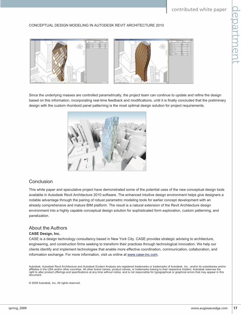
Since the underlying masses are controlled parametrically, the project team can continue to update and refine the design based on this information, incorporating real-time feedback and modifications, until it is finally concluded that the preliminary design with the custom rhomboid panel patterning is the most optimal design solution for project requirements.
Conclusion This white paper and speculative project have demonstrated some of the potential uses of the new conceptual design tools available in Autodesk Revit Architecture 2010 software. The enhanced intuitive design environment helps give designers a notable advantage through the pairing of robust parametric modeling tools for earlier concept development with an already comprehensive and mature BIM platform. The result is a natural extension of the Revit Architecture design environment into a highly capable conceptual design solution for sophisticated form exploration, custom patterning, and panelization.
About the AuthorsCASE Design, Inc.CASE is a design technology consultancy based in New York City. CASE provides strategic advising to architecture, engineering, and construction firms seeking to transform their practices through technological innovation. We help our clients identify and implement technologies that enable more effective coordination, communication, collaboration, and information exchange. For more information, visit us online at www.case-inc.com.
Autodesk, Autodesk Revit Architecture and Autodesk Ecotect Analysis are registered trademarks or trademarks of Autodesk, Inc., and/or its subsidiaries and/or affiliates in the USA and/or other countries. All other brand names, product names, or trademarks belong to their respective holders. Autodesk reserves the right to alter product offerings and specifications at any time without notice, and is not responsible for typographical or graphical errors that may appear in this document.
© 2009 Autodesk, Inc. All rights reserved.

18 www.autodeskcatalog.com/AECEdge spring_2009
Revit Cross-Disciplinefe
atu
re fo
cus
How to “BIM-Enable IPD”
Mostrecently,IfinishedworkingonthefirstIPDprojectontheeastcoast(how’sthatforasuperlative),Autodesk’sAECHead-
quartersinWaltham,MA.Tocciwasawardedtheproject with KlingStubbins in May of 2008 andobtained the Certificate of Occupancy on Janu-
ary15,2009.MyroleontheprojectwasasTocci’sBIMLead;togetherwiththeBIMLeadfromKlingStubbins,SarahVekasy,IwasresponsiblefortheBIM(youknow,BuildingInformationModel)onthisveryveryBIM-enabledproject.
Our process wasn’t perfect; we didn’t have too many IPD rolemodelstolookupto(Ithinktherehavebeenlessthan10IPDprojectsinthecountry..ever),butitworked.Idon’tknowifwhatwedidcouldbereplicatedonotherprojects,byotherteams,butperhapsIcanprovideajumpingoffpoint.
soME BACkGRounD on IPDIwon’tpretendthatIcanactuallyexplainthecontractualintrica-ciesofIPD(forthat,GoogleHowardAshcraft),butitishelpfultounderstandalittleaboutIPDbeforegettingtothe“howto”.
PureIPDrequiresasingletri-partycontractbetweentheprin-ciple participants: owner, architect and builder. There are 4overarchingprinciplesthatsupportIPD:
• Earlysubstantiveinvolvementofkeyparticipants• Joint risk and reward through an incentivized profit pool
–noonewinsunlesseveryonewins• Jointprojectmanagementwithdecisionsbyconsensus• Zerolitigation
TocciheldIPDsubcontractswithkeysubcontractorsthatheldthemtothosesameprinciples.
by: Laura Handler
➲
Figure 1: The project’s BIM Execution Plan (BEP) developed by Tocci, KlingStubbins and Autodesk

www.augieaecedge.com 1�spring_2009
Revit Cross-Disciplinefeatu
re focu
s
PlAnnInGBIM-Enabled IPD requires a shared model between design andconstruction.Thereisno“ourmodel”and“theirmodel”.WeusedseveralRevitfilestocompriseourmodel.Ourmodelswereorga-nizedbydiscipline;everyonehadaccesstoeverything,atalltimes.(SeeFgure1)
Before any modeling happened on the project, Sarah & I satdowntoestablishandnegotiateallofourBIMStandards,whichwedocumentedinourBIMExecutionPlan(BEP),seeFigure01.WehadtofigureouttechnicalRevitthingslikeworksets,phases,andbrowserorganization,butother,more“social”processes,forinstance,protocolsforwhenacentralfilecrashes.Wealsothoughoutsomewaytoachieve“gatekeeping”(translation:tomakesurethat Ididn’t inadvertentlymoveanythingIwasn’tworkingon),butwedidn’tendupusinganyofthembecausetherewassomuchtrustintheteam.
OneofourmajorplanningactivitieswasmergingourindividualRevittemplatestocreateaprojecttemplate.WemostlyusedthestandardswedevelopedanddocumentedinourBEP,butwedidrunintosomeissuesthatwehadn’tconsidered.Forinstance,wehadtofigureouthowtohandletheprojectnumberbecausewehavedifferentprojectnumbers(itactuallywasn’ttheworld’smostcreativesolution–wejustaddedaparameterforasecondprojectnumberforToccitouse).
Co-loCAtInGAkeycomponenttointegrationfortheprojectwasco-location.Duringthedesignperiod,IworkedtwodaysperweekatKling-Stubbins’office,at“my”desknexttothedesignteam.Originally,thiswasonlyoursolutionformodel-access–wheneverIneededtodoworkinthe(our)models,IwouldjustgotoworkatKling-Stubbins.Co-locatinggavemetheopportunitytoinputcontentinto the model as well as export information, but the majorityofmyworkatKlingStubbinswasn’tactualmodelcontribution.Iwasabletoreviewanddocumentmaterialselectionsandoptions,reviewscheduleandmilestones,explainmodelingstrategy,planmeetings,etc.Alotofthiscouldhavebeenaccomplishedoverthephone(andonthedaysthatIworkedintheToccioffice,itwas),butitwaseasierinperson.(SeeFigure2)
Moreimportantly,Ireallythinkthat itcreatedasenseofteamandunderstanding.During“their”deadlineweeks(forinstance,permitdeadline),Ireallyfeltthestressandtension,andonmore“fun”days(forinstance,thefoldingpaperdaysduringdesigncon-cept),Iwasabletounderstandtheconceptbehindtheirdesign.SinceIunderstoodwhythingswerehappening,IwasinamuchbetterpositiontocommunicatetootherteammembersatTocci.
MoDElInG stRAtEGyModelstrategywasbigpartofourBEP,butsomeofthe itemsdidn’tgetresolvedforseveralweeks.
WAllsWeknew fromthe start thatwewouldeventuallymodelwallsas three components, in the method ala construction, but wecouldn’tfigureoutwhen.Weendedupdoingitafewweeksbe-forethepermitsetwentout.Afterafewdiscussions,weagreedonamulti-stepplantodothis.Theprocesswastoolengthytodescribe,butitstartedwithKlingStubbinsdoingsomeorganiza-tionworkinthemodelwithwalls(settingwalllocationas:CoreCenterline).Then,Icameinandstarted“breaking”.Ihadaverysystematicapproach,includedbothtrackingprogressandaccu-
Figure 2: Reviewing the process for modeling walls in three
components
Figure 3: Illustrating the wall breaking concept

�0 www.autodeskcatalog.com/AECEdge spring_2009
Revit Cross-Disciplinefe
atu
re fo
cus
racy in Revit and on a printed 2D RCP (with several colors ofhighlighter,ofcourse).
Theresultingwallswerealittlebitmoredifficulttoworkwith,butwemadedo.Althoughthereweresomeissueswithgraphics(ina viewset to coarse, theedgeof eachwall can stillbe seen,makingdrawingslook“muddy”),Ithinktheymadedetailingwallsectionsslightlyeasier(atleastthatiswhatKlingStubbinssaid!).And the walls made construction much more streamlined; weusedthemodelforpartitionlayout(directtoTotalStation)andvisualscheduling.
lIGHtInG FIxtuREsThelightingfixturedebatewasn’thow,butwhere:inthearchitec-tureRVTortheMEPRVT.Architectureplacesthelightsandreferencesthemindesigndocuments,butMEPneedstoconnecttoandcoordinatewiththem.Weknewthattheycouldn’tbeinbothmodels(forquantitytakeoffreasons),butcouldn’tfigureoutthebestwaytoapproachthemforquitesometime.
Iwon’tgetintotheheateddebatewewentthrough,butluckily,we came to a conclusion just before we needed to start placingthem.ThelightswereplacedandannotatedintheMEPmodel,byarchitecture,andthenarchitecturereferencedspecificviewsinthelinkedfiles.
on sItENaturallythereisagreatdeal more I could writeabout our experiencesonce we got to work onsite.I’lltouchonjustoneforthisarticle.Wepostedthese renderings on site(Figure 04 and Figure05), so thatthe field staffwould have abetter senseof the overalldesign intentfor the af-fectedareas.
Forthisproj-ect,weplacedbetween 12and 14 ren-derings onsite. Even thoughwehaveasharedmodelwithKlingStubbins,theseareTocci-pro-duced renderings. We definitely benefited from the renderingsthatKlingStubbinsdidduringdesignbecausealotofthecustommaterialswerealreadysetupandwehadaccesstoalloftheJPGsKlingStubbinsused.
Itwasreallyexcitingtoplacetheboardsonsite-whenIplacedthem, the drywaller came over and started discussing how thecantileveredpieceofthecurvedwallcouldbesupportedaswellastheidealsequenceforinstallingthedrywallandthemetalceil-ings.Itwasexactlywhatwewerehopingwouldhappen!
Editor’s Note: If you are interested in learning more about this project, Autodesk created a video and it is posted at Youtube. You can watch the video using this web address:http://www.tocci.com/index.php?option=com_content&view=article&id=325&Itemid=356
She is the Virtual Construction Manager at Tocci Building Corporation, a construction management firm outside Boston, working to implement and integrate virtual construction into current practices. She began working with Tocci, implementing VDC/BIM, in June of 2006. Laura also manages Q5, a subsidiary of Tocci, which provides VDC and IPD Facili-tation Services. Laura serves as a leader of the AGC BIMForum, Boston Revit Users and Group and other industry organizations. She publishes her thoughts about her work at bimx.blogspot.com.
The Tocci Building Companies provides leading building services throughout the Northeast and Mid-Atlantic. Our philosophy is sim-ple — we all work for the project. We collaborate with our partners to actively serve the project, deferring individual objectives, to compel su-perior job performance and unqualified success. Q5 leverages Tocci’s knowledge and experience with VDC and IPD to provide facilitation services for projects around the world.
KlingStubbins is an internationally recognized design firm with over sixty years of experience providing professional services in all major disciplines within the realm of architecture, engineering, interiors, planning and landscape architecture. KlingStubbins is committed to design excellence and quality, in design, technology and service. We are nationally recognized leaders in sustainable design, consistent with our commitment to support the communities within which we work and live. We are innovators in project delivery, including BIM technology. Above all, we are focused on the needs of our clients, in-tegrating their business drivers into the creative process, resulting in projects of enduring value.
Autodesk, Inc. is a world leader in 2D and 3D design software for the manufacturing, building and construction, and media and entertain-ment markets. Since its introduction of AutoCAD software in 1982, Autodesk has developed the broadest portfolio of state-of-the-art Digital Prototyping solutions to help customers experience their ideas before they are real. Fortune 1000 companies rely on Autodesk for the tools to visualize, simulate and analyze real-world performance early in the design process to save time and money, enhance quality and foster innovation. For additional information about Autodesk, visit www.autodesk.com.
Figure 4 & 5: Renderings installed on-site

www.augieaecedge.com �1spring_2009
Revit Cross-Disciplinefeatu
re focu
s
A little Help From My Friends collaboration between consultants
thisisabriefoverviewofconceptsthatyoucanutilizewhenyouhaveanallReviten-vironmenttogreatlyimprovecollaboration
between building professionals and deliver yourprojectsontimewithhigherqualityandimprovedefficiency.Youcanbegintostudytheseconcepts
furtheriftheyapplytoyourprojectneeds.
sAME vERsIonTheteammustbeawareof theversionsofRevit thatare tobeusedinacollaborativeenvironment.Thisisnowaloteasierasall3Revitplatformsrefertotheyearrelease.Iftheprojectistospanacross a timezonewhenanewrelease ismade, the teammustcollectively agree that all members will upgrade at a particulartimeornot.
sAME BuIlD ItisimportantthateachdisciplineisrunningthesamebuildofRevit,withineachoffice&discipline.Ifthisisnotthecase,errorscouldresultwhenaSaveToCentralisdone.YoucandeterminewhichbuildyouviaHelpmenu>ProductLicenseandInforma-tion.ThebuildisdisplayedattheverytopasshowninFigure1.
lInkInG FIlEsLinking is thepreferredmethodforcollaborationandthesub-ject of this article. Linking allows use of Copy / Monitor toalertteammembersthatacopied/monitoredobjecthasbeenamendedbyanother team.Each team is incontrolof itsownpartoftheproject.
Onepossibledisadvantageisthatsometimesanelementmaybecreatedbyeachdiscipline. Anexampleofthis isaWC(toilet)createdinitiallybythearchitectthenrecreatedbytheMEPteam.OnlytheREvitMEPWCintheirfilecanbeconnectedtoaSani-taryandColdwatersystem.
Itispossibletouseaworksharedprojectinacollaborativeenvi-ronment,butthatisthesubjectofanotherarticle.
MAnAGEMEntEachteamforalargeprojectshouldhaveaBIMManageraspartoftheirstructure.TheBIMmanagerisanexperiencedRevituserwhoalsounderstands,intimately,thedemandsofhisownaswellastheotherdisciplines.TheBIMManagerswilldetermineandagreetotheteams’responsibilitiestominimiserework.Asanex-ample,Thearchitectsmaynotmodelthesanitaryfittingsforthe
➲
Figure 1: PRODUCT LICENSE AND INFORMATION
by: Bruce Gow

�� www.autodeskcatalog.com/AECEdge spring_2009
Revit Cross-Disciplinefe
atu
re fo
cus
reasonmentionedpreviously.TheArchitectsmayberesponsiblefortheceilingsbecausetheyarecontrollingtheceilingheightandthegridsetout.Inthiscase,theMEPBIMManagermaydeter-minethatthelightandMechanicalfittingsarenottobehostedelements. If the ceiling is moved they will need to move thesefittingsindependently.
CoPy / MonItoR toolTheCopy/Monitortoolnotonlycopiescertainelementsfromthelinkedfiletothehostfile,butalsosetsupamonitoringprocesssothatifachangeismadeinthelinkedfile,theuserofthehostfilewillbealertedwhenthelinkedfileisreloaded.Thereareonlycertainelementsthatcanbecopiedandmonitoredfromeachofthe3Revitplatforms:Grids,Levels,Columns,Walls&Floors.
YouwillnotethattheMEPteamcannotcopy/monitorceilings,forinstance.ItisimportanttobeselectiveaboutwhatiscopiedasRevitwillslowdownsignificantlyiftoomanyelementsarecop-ied.AtaminimumateamshouldplantouseCopy/MonitorforLevelsandGrids.
CooRDInAtIon REvIEWA Coordination Review warning displays, when monitoredelementshavebeenmodifiedandlinked.Thewarningscanbere-viewedusingtheCoordinationReviewcommand.Warningsareapplicable toelements in thecurrentprojectorbetweenahostandalinkedproject.Warningscanoccurbecauseoftheseviola-tions/conditions:
• Anoriginalmonitoredelementfromthelinkedprojecthaschanged.
• A copied monitored element in the host project haschanged.
• Boththeoriginalmonitoredelementandthecopiedelementhavechanged.
• Theoriginalelementinthelinkedfilewasdeleted.• Thecopiedelementinthehostfilewasdeleted
IntERFEREnCE CHECkTheInterferenceChecktoolfindsintersectionsbetweenthesolidgeometryorvolumeofelementsinaproject.Thesecanbeasetofselectedelementsorallelementsinthemodel.Itisimportanttounderstandthatprocessingtimeusingthistoolcanvarygreatly.Inalargemodel,simplycheckingallcategoriesagainsteachothercanresult inareport thatwill takeavery longtimeand isnotrecommended.
Toreduceprocessing time,selecta limitedsetofelementsoralimitednumberofcategories.Considerthe“lowhangingfruit”.Everyprofessionalhasasenseofwhichthingstendtoexperienceinterference coordination problems, like structure and HVACequipment. Interference Checking is fundamentally betweenCategoriesofelementswhetherinlinkedfilesorwithinthesameproject.Limitingthetooltoacoupleofexpectedcategoriesatatimemeanfewerreturnsandeasierverification/resolution.Thismeans thatyouwork through thevariousexpectedconflicts toverifyifyouhaveanyatall.Oncethoseareworkedoutyoucan
begintosearchformorearcaneissuesbychoosingtheircatego-riesinstead.
RElAtIonsHIPsIn a traditional arrangement, the Architect will commence theprojectandgetthefundamentalsofthedesignworkedoutinadigitalform.TheStructuralEngineerandMEPEngineerswillthen get this prelim design from the Architect and commencetheirowndesignworkanalyzingthebuilding’srequirementsandbegin integratingtheirworkwithinthecontextofthearchitec-turalframework.TheArchitectwouldthenreceiveandreviewtheStructuralEngineer’smodelbylinkingitintotheirownmodel.
Theworkflowrelationshipbetweeneachfirmischaracterizedbyusingthesefeatures:LinkingModels,Copy/Monitorandresult-ingCoordinationReviewsandInterferenceCheck.
WhataretheEngineersinterestedincopying/monitoringfromtheArchitectsModel?
What is theArchitect interested incopying/monitoringfromtheotherModels?
Primarily theArchitectwill runInterferenceCheckingagainstelementsintheStructuralEngineersModel.
ARCHItECt & MEP EnGInEERTheArchitectwillissuerevisionsastheprojectprogressestotheMEPengineer.TheMEPEngineerwillposition thearchitectsdesign incontext , createhisownspacesandzones,commenceanalysisandthenstartonthedesignfortheMEPsystems.TheMEPEngineerusesLinkedModelsandCoordinationMonitoras their primary coordination tools. In some cases, the MEPteammaymonitorlevelsintheArchitectsdesign.TheArchitectwillcoordinatewiththeMEPEngineerbyusinglinkedmodels
WhatistheMEPEngineerinterestedincopying/monitoringfromtheArchitectsmodel?
Levels Will they be used for structure orwillthestructurebeoffset?
Level and Grid Standards Dotheyagree?
Level and Grid Standards Willtheyberevised?Aretheysplitorcontinuous?
Walls Arestructuralwallsindicated?
Floors AreStructuralfloorsshown?Willtheyberevised?
Levels Sometimes,iftheyaddnewLevels
Grids Sometimes,iftheyaddnewGrids
Levels Sometimesthismaybenecessary
Level Standards Dotheyagree

www.augieaecedge.com ��spring_2009
Revit Cross-Disciplinefeatu
re focu
s
TheArchitectisprimarilyinterestedinrunningan Interference Check againsttheMEPelementsinthelinkedmodel.
stRuCtuRAl EnGInEER AnD MEP EnGInEERBothpartiesuseLinkedModelsandInterferenceChecking.
A CASE STUDY TO ILLUS-TRATE THE PROCESSStructural Engineer
1.Receives the Architectsmodel, then links it intohisprojectmodelfile.UsesOrigintoOrigintolink.
2.ChangesVisibilitysettingto Architecture ( or Co-ordination)
3.Selects Tools > Copy/Monitor>SelectLink(selectsthearchitecturalmodel)
4.Monitors or Copy/Monitors the elements in the architec-turalmodelthathedeemsnecessary.
5.Developsthestructuralmodel.
MEP Engineer1.ReceivestheArchitectsmodel,thenlinksitintohisproject
modelfile.HeselectsthelinkandcheckstheparameterforRoomBoundingintheTypeProperties.(Allowsthelinkedfiletodeterminespaces)UsesOrigintoOrigintolink
2.Changes Visibility setting to Architecture ( or Co-ordina-tion)
3.Selects Tools > Copy/Monitor > Select Link ( selects thearchitecturalmodel)
4.Monitors or Copy/Monitors the elements in the architec-turalmodelthathedeemsnecessary.
5.SetsuphisownSpacesandZones.6.DevelopstheMEPmodel
Architect1.Receives the Engineering models and links them to their
modelfileusingOrigintoOrigin.2.ReviewandCoordinateReviewwarningsandresolvethem.3.Run Interference Check between selected elements of the
linkedmodelsandtheirs.4.Ifnecessaryelecttocopyandormonitorengineeringlevels
fromtheothermodels.
When Models Change1.Awarningdialogueappearswhentherevisedmodel’slinkis
loaded.2.Thechangescanbeviewed–Tools>CoordinationReview
>SelectLink.3.The Coordination review dialog reveals the alert and gives
the host the opportunity of Accepting, Rejecting or Do-ingNothing. (IfaMonitoredelementhaschanged, thenModify,RenameorMoveareavailable)
4.Thearchitectreviseshismodelasnecessaryandreissuesittotheconsultants.
Structural Engineer1.ReceivestheArchitectsrevisedmodel.Savesit inthesame
locationasthepreviousversion.2.Whenitisreloaded,theymaybealertedtochangesbythe
Coordination Monitor for Monitored or Copied elementsonly.
3. Follow the process outlinedabove for the architect and In-terference Check. Note thatcommentsmaybeaccessedusingthe“InaLinkedProject”tab.
MEP Engineer:1. Receives theArchitects and/or Structural Engineers modelandthenlinksitintohisownproj-ect,savinginthesamelocationas
thepreviousversion.2.ReviewandCoordinationReviewitemsifnecessary.3.UseInterferenceCheck.(Tools>InterferenceCheck>Run
Check.)4.AddressanyelementsidentifiedbytheInterferenceCheck.(
OpenanInterferenceReport).Refreshaftereachconflictisresolved.(Tools>InterferenceCheck>ShowLastReport)
Theprocess is reiterated.Eachdisciplineaddress issuesrelativetotheircontextbutinthefullknowledgeofthebuildingmodel.Naturallyyourprojectconditionsmayvary.Itisimportantthateachfirmcommunicateswitheachotherfrequentlyandthateachfirm’steamunderstandsthesetools.Withoutthemtheproject’scollaboration/coordination effort may not be improved muchoverexistingpractices.
Bruce is a registered architect who has worked as everything from print boy to director. His architectural background includes work on a wide range of project types, including com-mercial high-rise, hospitality, health care, and residential/commercial developments. He is a Revit; Implementation Architect/Applications Engineer with KarelCAD. He works in Aus-tralia and New Zealand, where he demonstrates Autodesk products; trains and implements Revit; Architecture, Structure, and MEP; and supports Autodesk products for a broad client base. Bruce is active in the Revit community, organizing the Revit User Group Brisbane (RUGB ). He is a moderator for the Autodesk User Group Inter-national Revit Community , a speaker at Revit conferences, and he writes a blog on Revit topics called “Revitalise”.
you can begin to study these concepts further if they apply to your project needs...

�� www.autodeskcatalog.com/AECEdge spring_2009
Revit Cross-Disciplinefe
atu
re fo
cus
Extending BIM Design value using the Revit API
anapplicationprogramminginterface(API)allows users and developers to extend thecapabilities of an existing application by
writing a program or script that adds new func-tionalitytothesoftware.TheAutodeskRevitAPIallows programmers to change elements in the
BuildingInformationModel(BIM)directlyortoaccessthedatatoperformspecializedtasks.
PowerusersandsoftwaredevelopersaretakingadvantageoftheRevit API to create their owncustomtools.ByusingtheRevitAPI, they are able to enhanceRevit’s power to improve work-flows and create better buildingdesignsfaster.Thisarticlewillin-troducereaderstotheRevitAPIandpresentsomeofthewaysthatdevelopersanddabblersalikecanuseittosuperchargeRevit.
A WoRk In PRoGREssThe Revit API is still relatively “young,” especially comparedto AutoCAD with its more than 25-year history of APIs andcustomizations. Autodesk officially introduced the Revit APIin Revit 8, just over four years ago. Since then, it has steadilyexpandedandimproved.Whiletherearestillsignificantlimita-tions,theAPIhasnowreachedapointwhereitisquiteusefulforsolvingawidevarietyofproblems.ThekeyistounderstandthestrengthsandweaknessesoftheAPIandwhether itpresentsagoodfitforyourparticularneed.
SomefunctionswhichareagoodfitfortheAPItodayinclude:• dataextractionandimport• geometryextraction• propertymanipulation• buildinganalysis
• basicdesignautomationandconfiguration• simplefamilycreationandmanagement• automatedexportandprinting
Somefunctionsthatstillneedrefiningtoday,butwillnodoubtbebettersupportedinfuturereleasesinclude:
• interactive(pickandplace)applications• larger-scaledesignautomation• batchautomation
PRoGRAMMInG: vstA vERsus vIsuAl stuDIoAutodesk offers two ways to learn howto program with Revit. Developers canchoose between different programmingenvironments: Microsoft Visual StudioorMicrosoftVisualStudioToolsforAp-plications(VSTA).
For people already familiar with pro-grammingAutoCAD,theVisualStudio
approachissimilartoprogrammingAutoCAD.NETorObjec-tARX, in which commands are built separately, compiled, andthentestedinsidetheCADsystem.
ProgrammingusingVSTAisconceptuallysimilartoVisualBa-sicforApplications(VBA),wheredevelopersworkinsideoftheCADsystemandbuildprojectstoembedintoaRevitdocumentortokeepinaseparateprojectfile.
Thegoodnews is that thedebateaboutwhether touseVSTAorVisualStudio israrelyaboutthe“power”ofaparticularap-proach,whichwasoftenthecasewhenworkingwithAutoCAD.WeighingthebenefitsofVSTAorVisualStudioismoredepen-dentonthespecificprojectobjectives—specifically,deploymentissuesandwhowillbedoingthedevelopment.Bothusethesamelanguages (Visual Basic.NET or C#) and the API is almost
➲
by: Matt Mason
Figure 1: Manage Ribbon Tab - Macros Panel - VSTA Tools (Macro Manager & Macro Security)
the revit aPi is still relatively “young,” especially compared to autocad...

www.augieaecedge.com ��spring_2009
Revit Cross-Disciplinefeatu
re focu
s
identical.However,VisualStudiohasapproximatelytenpercentmorecapabilitiesinRevitthanVSTA.
Intermsofcost,VSTAisfreeandincludedintheRevitinstallinRevit2010products).Thefree“Express”versionofVisualStu-diohasenoughcapability–withafewlimitations.Progressivelymorepowerfulversionscomewithhigherpricetags.ThebiggestbenefitofVisualStudioisthatitiseasiertodevelopapplicationswithsecuresourcecode.InVSTA,thesourcecodetendstobevisibletoanyoneinterested.Therearealsodifferentapproachestodeploymentofapplications in theVSTAversusVisualStu-dio approaches. For the serious developer, Visual Studio alsoprovidesaccesstoanext-generationuserinterface,databaseinte-gration,andothertools.
UsingVSTA,all“macros”areaccessibleonthe“Manage”ribbonunder“MacroManager”.UsingVisualStudio,thedeveloperde-fines “Commands”whichareavailableon the “Add-Ins” ribbonunder “External Commands.” Visual Studio also allows pro-grammerstodefine“Applications”torunwhenRevitstartsup,aswellastofurtherenhancetheuserinterface,includingmakingsimpleRibbonBarPanels.WhileVSTAisagoodwayto“dipa
toe”intotheRevitAPI,themoreseriousprogrammerwillwanttouseVisualStudio.(SeeFigures1and2)
lookInG At vIsuAl BAsIC CoDEThe sample source code below (Figure 3) shows an example ofwhatprogrammingwiththeRevitAPIislike,includingscanningtheRevitproject forcertainelements (rooms), then interactingwiththerooms.Inthiscase,itshowshowtoreadinformation,suchas theperimeter,orwrite information, suchas theRoomFloorFinish.(SeeFigure2)
ConFIGuRInG REvIt FoR ADD-InsDo-it-yourself programmers who create Add-Ins that performa useful function can modify the REVIT.INI file to tell RevitwheretolookforthenewAdd-In.AnexampleisAvatech’sDoorMarkUpdateadd-in,whichautomatesdoormarkupdateswhenchangesinevitablyoccur.
ToaddasimplecommandtoRevit,userscanaddorupdatethe[ExternalCommands]sectionoftheirINIfile(Figure3).
Figure 2: The Add-Ins Ribbon
Figure 3: Programming with Revit API Using Visual Basic

�� www.autodeskcatalog.com/AECEdge spring_2009
Revit Cross-Disciplinefe
atu
re fo
cus
The“ECCount”setting(Figure4)describeshowmanyExternalCommandsare in theINIfile.Thenprogrammersneed tode-finethefollowingfourlines(Figure5)foreachcommand(where<num>indicatesthenumberofeachcommand):
External Applications are similar to External Commands, butinsteadofencapsulatinganewRevitcommand(whichrunsonadocument),theExternalApplicationworkswiththeRevitap-plication in general. It can be used for mundane purposes like
settingupacustomizeduserinterface(withcustomcommands,menus, and toolbars)—or for more interesting purposes likekeepingtrackofdifferenteventswithinRevit.
ConfiguringRevittoworkwithExternalApplicationsissimilartoExternalCommands,butinadifferentsectionwithintheRe-vit.INIfile.
EACount,asseeninFigure6,referstothenumberofExternalApplicationsandeachapplicationmusthaveaClassNameandanAssemblyPath.
The Revit Software Development Kit (SDK) download, avail-ablefreefromAutodesk,containsatoolcalledthe“RevitAdd-inManager”thatautomatestheprocessofloadingAdd-InstotheRevit.INI file. Commercial developers create install programsthat modify the Revit.INI file automatically, so this process isnotusuallynecessaryforcommercialsoftware.Finally,moread-vancedfirmsmaykeepacentralizedcopyoftheREVIT.INIfilethatisdeployedtoeachmachineinanautomatedfashion.
lEARnInG tHE APIAnyonecandownloadthefreeRevitSDKfrom(http://usa.au-todesk.com/adsk/servlet/index?siteID=123112&id=2484975)
The SDK provides good documentation, beginning with the“Help”file.Italsoincludesa“GettingStartedGuide,”aswellasamorein-depth“DeveloperGuide.”AutodeskhasalsopostedavideotrainingclassontheSDKpagetitled“DevTV:Introduc-tiontoRevitProgramming.”Finally,therearediscussionboards
onboththeAUGIandAutodesksitesspecificallytargetingRevitdevelopmenttopics.
TheRevitAPIhasnowreachedastageofmaturitywhereitcansignificantly improvehowfirms leverageRevit.AsBuildingIn-formationModelingcontinuestoenterthemainstream,theearlyadoptersoftheRevitAPIwillhaveevengreateradvantagesovertheircompetitors.Forthosewhohavepreviouslyperformedcus-tomizationsinAutoCAD,perhapsnowisthetimetolookattheRevitAPI.Matt Mason and his software team at Avat-ech Solutions engineer new applications that improve the bottom line by automating and streamlining processes for manufacturing, architecture, engineering, and facilities manage-ment organizations. Matt has a long history orchestrating systems integration and software development in computer-aided design for man-ufacturing. He speaks about software development at Autodesk events across the country, and blogs at http://cadappdev.blogspot.com
Figure 5: Explaining each line of information that you need to add.
Figure 6: Configuring Revit to Work with External Applications
Figure 4: Updating the External Command Section of Revit’s INI
File
WHAt’s nEW In tHE REvIt 2010 API: GEoMEtRy(Part of the What’s New in the Revit 2010 API series)
TheGeometryareaoftheRevitAPIhasafewinterestingandhelpfulenhancementsinthe2010version.
ProbablythemostobviousoftheenhancementsweremadetosupportRevit’snewconceptualmassingcapabilities.
HERMITESPLINEWhiletherewaspreviouslyaHermiteFaceclasstorepresentthesurface–wenowhaveaHermiteSplineelementforthesplinesthatcanbecreated(whichwillprobablyresultinmanymoreHermiteFacesaswell–sinceitonlytakesonebuttontogofromsplinetoface).
The HermiteSpline exposes its control points and tangentvectors(nicetouch).WARNING:Forthoseofyouwhohavebeen using Tessellation – like we have on our Earth Con-nectorapplication–beprepared foranexplosionofpointsasRevitUsersstartusingsplines.The5-pointsplineshownabovetessellatedinto287points…(Iprobablyhavetostartinvestingsomementalenergyina“reduce”function–because
that’sprettyheavy!).
POINTAsIjokedaboutinoneofthepreviousposts–AutodeskhasfinallybrokendownandaddedthePointconcepttoRevit(yes,yes–theXYZclasswastherebefore–butPointsarenowfirstclassgeometricobjects).
View full article online at: http://cadappdev.blogspot.com
mat
t m
aso
n b
log
sp
ot

www.augieaecedge.com �7spring_2009
Revit Cross-Disciplinefeatu
re focu
s
A trainer’s Perspective: key requirements for a successful biM implementation
MovingtoBIMisa“businessdecision”.It’sless abouta simple “CADupgrade”andmoreaboutadeliberatebusinessdecision
madebyownerswhoknowthatBIMwillimpacttheirfirmatalllevels.Oncetheownershavemadethisdecision,thefirstaspectofthisventureisfor
theownerstosupporttheirstaff.
The key group of individuals needing the most support duringthis transition is the project managers. They are the ones whoareresponsibleforprojectdeadlines.TheyneedtobetoldbytheownersofthecompanythatBIMisthestrategicfutureoftheirfirmandthattheownerswillsupporttheirneedsinordertogetthe jobdone. It is fair to say thatarchitecturalfirmswhohavemadeasuccessfultransitiontoBIMhavedonesowithaggressivesupportfromthefirm’sownersandexecutivestaff.Saidanotherway,otherfirmsstumblewithimplementingBIMbecausetheirProject Managers lack the support from the owners and theirprojectsinevitablyreturnto2DCAD.
The move to BIM is a gradual change. One should avoid anovernight,office-wideshifttoBIM.Instead,thechangeisdoneprojectbyproject.Asnewprojectsentertheoffice,BIMteamsareappliedtothoseprojects.AsforexistingCADprojectsthatarepast30%DD,itisrecommendedtheyremainin2DCAD.
It isessential tohandpick therightprojectmanagerandteammembersforthefirm’sfirstBIMproject.Lookforpeoplewhoare“open-minded”andflexiblewhenitcomestotheirworkmethodswithCAD.BIMdemandsgreatpatiencefroma“new”userandthe PM must understand that his or her team will go throughvariouslevelsoffrustrationduringtheir“first”BIMproject.Oneshould also be looking for team members who are enthusiasticandenjoysharingtheirknowledgewithothers.OncethefirstsetofnewusershasgonethroughtheirfirstBIMproject,theycanbeplantedintofutureprojectteams.Onemustbeawarethatonceafirstteamgetsthroughthepainfullearningcurve(andyes,itwillbe“painful”attimes)duringtheirfirstBIMproject,theybecomeahugeassetandsupporttofutureteamsnewtoBIM.
One other key aspect of a proper BIM implementation is thetranslation of your existing office CAD standards into BIM.Projectmanagerscanbequitepassionateaboutthegraphicqual-ityof theirprojects. If thePMmakesaprintofaplan,sectionandelevationviewoftheir“new”BIMprojectanddiscoversthatthe lineweights, dimension tick marks and text heights don’tmatchtheirexistingofficegraphicstandardsperfectly,heorshe
couldpotentiallyclosetheBIMprojectthatdayandreturnto2DCAD.OnecanexpectanexperiencedBIMusertotakeaboutaweektotranslateexisting2DCADbasestandardssuchastitleblocks,lineweights,dimension/textstylesandcustomdoorandfinish schedules. Once the BIM standards are set, the trainingof thestaffshouldbegin.If thetraining isdonefirst,yourfirstBIMprojectwillnothavetheproperofficeBIMstandardgraphicsettings.
REquIREMEnts FoR PRoPERly tRAInInG youR oFFICE stAFF In BIMWhenmoving toBIM, it isnot simplyanannual softwareup-gradethattheCADuserscanteachthemselves.BuildingaBIMmodelrequiresthere-educationofstaffonhowaproject isde-signedanddocumented.IftheusersarenotproperlytrainedanduseBIMlike2DCAD,theirchancesoffailurearequitehigh.Ifthefirm’smovetoBIMistobesuccessful,trainingisrequired.Iftrainingforthestaffisnotplanned,makingthechangetoBIMisnotrecommended.
Oneshouldalsoconsiderdifferenttypesoftrainingforvariousstaff within an office. The most important group that requirestraining first is the firm owners and senior staff. This is bestprovidedthroughahalf-daypresentationthatexplainsanddem-onstrateswhyBIMisanessentialbusinessdecisionfortheirfirm.Itisimportantthatthisgroupunderstandsalltheramificationsofthischangeanditsimpactonalllevelsoftheirbusiness.
The next group of users that requires training is that of theprojectmanagerswhodonotuseCADday-to-day.Asingledayhands-onclassshouldbeenoughtimetoteachthesePMshowtomaneuverthroughtheBIMmodel,findviews,addanote,checkadimension,viewasheetandmakeaplot.It’scriticalthisgroupunderstandsandcancontributetotheorganizationoftheirproj-ectwiththeirteam.Iftheyarenotincluded,theymightbecomealienatedfromtheBIMprocess.Thiscanhavenegativeimplica-tionsontheprojectandresultinnegativityforfirmwidesuccessoftheimplementation.ProjectMangersneedthiskindofinclu-sionintheprocess.
Thefinalgrouptobetrainedistheproductionusers.Theirhands-onclassisthemostintensiveandwilltakethelongest.Thisclassshould be for “production users” who will be using BIM day-to-day.Theidealattendeeforthisclass isaprojectmanagerorprojectarchitectwhousesCADdaily.Thesearetheperfectusersgiven their knowledge and past architectural experience. They
by: Cyril Verley
➲

�8 www.autodeskcatalog.com/AECEdge spring_2009
Revit Cross-Disciplinefe
atu
re fo
cus
willbetheonestomentortherestoftheproduction(junior)staff.Expectthistypeofclasstobesplitintotwo,one-weeksessions.
tRAInInG BIM WItH “tRAIn tHE PRojECt”® In our industry, there are many companies that provide BIMtraining (for production users) with a three-day class using a“generic”buildingtypethathaslittleornoconnectionwiththetypesofprojectsdesignedinanactualoffice.Thistraininghasseensomesuccessbutitisnotthemosteffectivetypeoftraining.
Instead, the “ideal” training experience for production users isatrainingprocesspioneeredbyCDVSystemscalled“TraintheProject”®whichmeanstotrainononeortwooftheclient’sown“live”officeprojectsusingtheclient’sowncomputerswithintheclient’sofficeenvironment.Thistypeoftraininghasbeensuccess-fullyusedatfirmssuchasHOK,SOM,AECOMandNBBJ.Itisanintenselyfocusedlearningexperiencefortheproductionstaff,teachingexactlywhattheyneedtoknowtobuildtheirliveofficeprojectsusingBIM. If thequestionsof theusersattending thetrainingpertaintobuildingacurtainwallorcustomstairtheydesignedwithintheirownproject,theirclasstimewillbemorefocusedandmoreproductive.
LearningBIMisaverylargeundertaking.ThequantityofwhatneedstobelearnedistheequivalentoflearningAutoCADandArchitecturalDesktopsimultaneously.Thebestoddsofsuccesscome from dividing the “Train the Project” training into twoparts.Theusersspendtheirfirsttrainingsessiongoingthroughallthecommandstobuildallthemajorcategoriesoftheirproject(i.e.usingwalls,doors,windows,floors,roofs,noting,dimension-ing, sheet setup, printing, etc). Once that first training sessionis completed, the users continue working on theirproject for aperiodofaboutseventotenweeks.Duringtheseventotenweekperiod,aspertheinstructionsfromtheirBIMtrainer,eachuserwillkeepa logofquestions regarding theconstructionof theirnewBIMproject.Whenthesecondsessionof“TraintheProject”trainingoccurs, eachuserwillpresent,duringclass time,a listofBIMquestionsspecificallyrelatedtotheirproject.Oncethosequestionsareanswered,theclasscontinueswithmoreadvancedBIMfeatureswhichdrilldeeperintotheprogramandwhicharealwaysrelatedtotheirproject-specificissues.
Therearebonusesthatcomewith“TraintheProject”:• TheproductionusersarelearningBIM.• These same users are learning BIM by building their own
“live”officeprojects.• With the guidance of the trainer, the users are also learn-
inghowtobuildandorganizetheir liveofficeprojectfromscratch.
• By the time thefirstweek longsessionof training isdone,whattheyhavebuiltduringclasstimebecomestheirofficeprojectgoingforward.
• If the BIM office standards were done properly, the userswouldalsobelearninghowtousetheirnewofficestandardsduringclasstimeANDfortheirfirstproject.
• Sincetheusersareactually“working”ontheirofficeprojectduringclasstime,thefirmcanexpectthat40to50%ofclasstimebecomes“billabletime”totheproject.
WHEn sHoulD “tRAIn tHE PRojECt” oCCuR?Forfirmsinterestedintheideaof“TraintheProject”,itisrecom-mendednottotrainonaprojectthatisinschematicdesign.It’sdifficultenoughtolearnanewBIMsoftwareprogramwhileatthe same time keeping up with ongoing project deadlines. It isasking toomuchofanyuser tohave them learnBIM,keepupwithprojectdeadlinesanduseBIMasan “SDdesign tool”ontheirfirstBIMproject.Twooutofthreeisokay,butifusersaretoldtheyneedtodoallthree,thereisthehighprobabilitythattheirfirstBIMprojectwillfailandreturnto2DCAD.
Instead,thistypeoftrainingshouldbescheduledwhentheofficeprojecthasbeenbroughttothestartofdesigndevelopmentlevelusingexisting2DCAD.IftheprojectisataDDlevel,themajordesigndecisions havealreadybeen made, allowing theusers tofocuson specificmodeling issuesduring theclass. In theclass,theDDsetofCADfilesareimportedintotheplanviewoftheBIMmodeland“traced”bytheusers.Theusers thencontinuebuildingtheirprojectmodelwhilelearningBIM.
UsingBIMasaSDtoolispossiblebutnotforauser’sfirstproj-ect.OncetheusershavegonethroughacompletedBIMprojectinDDandCDs,theyknowhowtomaneuverthroughtheentireBIMprogram.TheirnextBIMprojectcanthenstartatanearlierphaselikeschematicdesign.
WHAt HAPPEns AFtER tHE FIRst WEEk oF tRAInInG?Toreiterate,implementingBIMrequireschangesatalllevelsofan organization. Once the first week of training is completed,therearesomekeyprotocolsthatmustbeputinplaceifBIMistoflourishwithintheoffice.First,theprojectuserswhohavebeentrainedMUSTremainontheprojectusingBIM.TheyarenewtoBIMandinordertotakefulladvantageofthetraining,theyneedtoremainworkingontheirprojectforatleastseventotenweeks.Once theyhavegone through this initial learning curveandhavecreatedtheir listofadvancedBIMquestions,theyarethenreadyfortheadvancedtrainingclass.If,however,theyarepulledfromtheirBIMprojecttooearlyandputontoanon-BIM,2DCADproject,theywilllosetheirBIMtrainingwithinseventotendaysandwillberequiredtorepeatthefirstBIMtraining.
AnotherkeyaspectofasuccessfulBIMtrainingexperienceistoplace thedesksofall the teammembersclose together.Unlike2DCAD,BIMprojectsdemandmorecommunicationbetweentheteammembers.If theteamisspreadthroughouttheoffice,communication becomes more difficult among team membersand will negatively impact on the quality and quantity of theirBIMwork.ItisalsorecommendedtoseatnewBIMusersnexttoexperiencedusers.Tobeanexperienceduser,onefirstneedstocrossthelearningcurveonatightrope.Ifthereissomeoneclosebytoofferslight“nudges”ofhelp,theywillmakethattrekmorequicklyandlesspainfully.

www.augieaecedge.com ��spring_2009
Revit Cross-Disciplinefeatu
re focu
s
AllusersnewtoBIMwillexperiencevariouslevelsoffrustration:itisunavoidable.Thecauseisaformof“2DCADBrainwashing”.AllusersnewtoBIMneedtimetobreakthemselvesfromtheirpast2DCADhabits.Infact,oneshouldnotbesurprisedtohearcommentsfromgreenBIMuserssuchas:“Icandrawthisfasterusing2DAutoCAD”.Don’tworry.Ifyoutellthemtopersevereandyougivethemtheopportunitytogetthroughthisverysteeplearningcurve,theywillgetthroughitandbecomebelieversofBIM. Again, be sure to seat your team properly to reduce thefrustrationtheywillexperience.
BIM’s REtuRn on InvEstMEnt Again,theBIMlearningcurveissteep.Thereshouldbenoex-pectedROIfromauser’sfirstproject.Infact,theprojectmightbreak even or require additional time to complete. However,onceauserhasgonethroughaDDandCDprojectexperience,thestartoftheirnextBIMprojectwillbethestartofROI.So,dependingonthesizeofyourprojects, itcouldbefivetosevenmonthsbeforeaROIisseen.
But keep in mind: if your first BIM project is well built, youshould see a savings during the construction administrationphaseofthatproject.Again, iftheessenceofBIMis“acoordi-nateddocumentset”,thenCAshouldbeapleasantsurprisewithfewchangeorders.
Movingforward,oncetheteammembershavebeengiventheop-portunitytoexperienceBIMonatleastonecompletedproject,adramaticsavingoftimewillberealized.TheBIMprojectteamswillnotrequireasmanypeople,theywillproducemodelsmorequicklyandtheywillbeabletocreate3Dvisualsatafractionofthecostofsendingitoutofhouse.Andagain,therewillbetheaddedbonusofasmoothCAphase.
One more recommendation for offices ramping up with BIM:Most BIM products have all kinds of “nifty” features such asrendering,animation,photorealisticimaging,marketinggraphics,etc.WhiletheteamnewtoBIMmightstartoffattemptingtofocusontheseadvancedfeatures,theymustbetoldtheirprimaryfocusfortheirfirstBIMprojectisa“coordinateddocumentset”,nothingmore.Timeandagainprojectteamsspendpreciousbillableprojecttimeon3Dgraphicsandlosesightoftheirprimaryfocus.
GoInG FoRWARD WItH BIMOne final thought: For years we have been numbed by all thepromiseswehaveheardconcerningwhat2DCADwillfix.BIMisnowhereanditcouldnotbemoreexciting.DuringthetimeyourofficeisbringingBIMonline,itisrecommendedtorequestyourbusinesspartner,yourprojectmanagersandyourproduc-tion staff to avoid sharing any details about the use of BIM atyourofficetofolksoutsideyouroffice.
That’sright.Youshouldnottellyourcolleagues,yourcompeti-torsandespeciallyyourclientorcontractoraboutthedetailsofyourBIMusage.TimeandagainaprojectmanagerproclaimstohisorherclientthevirtuesofBIMandwhentheclientdemandsresultsaweeklater,theproductionusersareunabletoperformbecause they are still green to BIM. Many firms have waited
monthstoayearormorewhilepreparingtheirstaffbeforean-nouncingtheiruseofBIM.ThisisanimportantpointtowaituntilyourofficeisfullyentrenchedinBIMbeforemakinganyformalannouncement.
BIM’sultimate impactwithinanAECfirm is thecall tobringthe three major parties of a project more closely together: theOwner,theArchitectandtheBuilder.BIM’seffecttoathreewaycontract,knownas“IntegratedProjectDelivery”isthepinnacleofcontractualcollaboration.RecognizingIPD’smomentum,theAECindustryisprovidingnewcontractualdocumentationsuchastheAIAdocument:C195SinglePurposeEntityAgreementfor IPD or the Consensus Doc 301 for IPD. These contractsconsider the implicationsofallowing theowner, thecontractorandthearchitectopenaccesstotheBIMproject.Thisaccessibil-ityhopestokeepprojectsontime,onbudgetandwithreducedconstructionerrors.However,onemustalsoconsidertheliabil-ityofaBIMaswellasthepotentialexposurenotonlyofallthedatainthemodelbutalsoofalltheinherentBIMstandardsofthefirm,initselfrepresentingasubstantialinvestment.MovingtoBIMisasoberingendeavor;onewhichinvolvessupportfromtheowners,Executivestaffandawellthoughtoutplanofaction.ThebenefitsofBIMfaroutweigh thechallengesandbring thepatientuserclosertotherealbuilding,allowingamorecompleteviewofthemodel.ThereisnodoubtBIMisheretostayandwillcontinuetoimpactthebusinessofdesignandconstructionforyearstocome.
EditorsNote:Thisarticlewaswrittenandintendedasacompan-iontoanotherarticlewrittenandpublishedelsewhereearlierthisyear.Initsoriginalcontextthisarticlewastitled“TheBusinessofBIM-Part2”.Unfortunatelyweareunabletoincludethefirstpart“TheBusinessofBIM-Part1”.Ifyouareinterestedinread-ingthiscompanionarticleyoucanfindithere:h t t p : // w w w . c d v s y s t e m s . c o m / c o n t e n t / i n d e x .php?option=com_content&view=article&id=111:the-business-of-bim-part-1&catid=17:press-releases&Itemid=30
*“Train the Project ”training was inspired by a comment made by a client of CDV Systems nearly five years ago. During a BIM class, this client commented that his concern was not the cost of the training, but rather the loss of $65,000 per week of “non billable hours” as a result of BIM training on a “generic model”. Within a week of that conversation, CDV Systems developed its unique approach to BIM training.
Cyril Verley, founder of CDV Systems has been practicing architecture for 23 years, reg-istered for 18, an AEC consultant for the past 15 years with the last 7 years focused on Revit services (14 months prior to Autodesk’s purchase of Revit). He can be reached at [email protected].
CDV Systems, Inc. (www.cdvsystems.com), founded in 1993, is a pri-vately owned consultancy offering a full range of on- and off-site Autodesk Revit Architecture, Structure, MEP and CodeBook services for all user levels for clients worldwide. For more information, please contact us at http://www.cdvsystems.com/content/index.php?option=com_contact&view=contact&catid=11&id=1

�0 www.autodeskcatalog.com/AECEdge spring_2009
Revit Cross-Disciplinefe
atu
re fo
cus
A General Contractor’s venture into BIM and vDC
a recent phone conversation with our localsoftwareresellerstarted:“Pleasehelp!I’vebeensellingalotofRevitandNavisworks
licenses to local Contractors because they lovewhatBIMcando.AndI’mholdingalotofclassesandmostofthestudentsarepickingupthesoft-
ware well.” And he continued, “But, I keep getting calls a fewweeksfollowingthetrainingasking, ‘Nowwhat?Nowthatmyteamknowshowtousethesoftware,howdowedoBIM?’How’sanyoneelsedoingBIM?...andIdon’tknowwhattotellthem!”
Coincidently,IwascontactedbySteveStaffordwithAUGIthenextdaytowriteanarticleabouthowBIMisbeing utilized by General Con-tractorsanditsbenefits.
MotIvAtIon FoR ADoPtInG BIMMy Employer, CurrentBuilders looked to BIMtechnology in order tosave money and
pursue a fundamentally improved method of delivering all ofourprojectson-time,atorunderbudget. Asaresult,wehavebeen successfully preventing significant coordination errorsof allkindsona full rangeofprojects. Resources suchas theAGC’s Contractor’s Guide to Building Information ModelingandnumerousConstructionUsersRoundtable(CURT)white-papershavegivenCurrentBuilders’leadershipanavenuetowardchangingthewayweplanandperformasacompany.Thesepa-pers emphasize that although Building Information Modelingis technicalandquiteexpensive,mastering the technologycanandhashadindustry-alteringeffects.Further,applyingBIMef-fectivelyofferspredictable,consistentandreliablewaystoplanand prevent many problems with the entire building processincluding the building lifecycle. The benefits reach all cornersoftheAECindustry,muchlikethesamefundamentaltechnol-ogyandprocesseshavedoneandcontinuetodoforEngineeringandManufacturingindustries.Theincreasingcomplexityofthebuildinglifecycleprocesses,legalrequirements,anddocumentationshouldresolvetheentireAECindustrytoreducedelays,rework,
legaldisputesandmiscommunication.BIMpresentsuswiththecapacitytoaccomplishthesereformations.
DEFInInG BIM AnD vDCThere are seemingly endless
variations of the composi-tionanddefinitionof‘BIM’and if there isa consensusonthefundamentalmean-
ingthenIcertainlymissedthememo.Muchtothe
chagrinof thosewho advocate
an all-en-compassingdef i n it ionof BIM,we’ve optedto limit theacronym toregard the
fundamentalt e c h n o l o g i e s
centered on rela-tionalbuildingdata.
At Current Builders and
➲
by: David Thirlwell

www.augieaecedge.com �1spring_2009
Revit Cross-Disciplinefeatu
re focu
s
other industry organizations, it is becoming established thatBuilding Information Modeling (BIM) refers to a set of tools(i.e. the technology, toolset, or ‘means’) and Virtual Designand Construction (VDC) encompasses the processes, goalsand concepts (i.e. ‘methods’) of applying BIM as well as othertechnologies.VDCinvolvesthecommunication and collabora-tionbetweenprojectparticipantsusingtoolsetsasdiverseasBIMand product lifecycle manage-ment (PLM)systemsaswell asestimating and scheduling sys-tems.
I have observed that Contrac-tors and leaders in relatedfields are less interested in thetechnical ‘means’ofBIM,thanin the processes and ‘methods’of VDC. Therefore, Contrac-tors are trying to get a graspof what BIM means in thegreaterparadigmofVDCandof any changes to traditionalproject relationships, such asIntegrated Project Delivery(IPD),thatmaybeacceleratedasaresult.Whileafloodofar-ticlesaboutBIMfocusonwhatcanbedoneusingBIM,mostdonotevenhintathowtoachieveastrategyforapplyingthesecapabilities.Thislackofstrategiccommunicationisparticularlytrueinregardtoconstruction-relatedapplications.Furthermore,thereareveryfewsourcesthatdescribewhatVDCproductionmightcompriseforaContractor.
IMPlEMEntInG vDCForCurrentBuilders,VDCisstill largelybeingintegratedin-house in the absence of BIM collaboration with other projectteammembers. JohnTocci,Sr.oftheAGC’sBIMForumhascoined the term “lonely BIM” to refer to this typical, early-adoption arrangement. This is not to say that we have or aregoing-it-alone,butthatcollaborationwiththeowner,designers,andsubcontractorsisperformedthroughlivemeetingsand/orasemi-manualexchangeofdataasopposedtoanativeBIMcol-laborative environmentor “socialBIM.”ThemajordistinctionisthatunderlonelyBIM,thereisagreaterrelianceonthecom-petenceoffewerindividualstoconstructthediscipline-specificBIMmodels:oftenfromexistingconstructiondocumentation.VDCinthelonelyBIMscenariothusreliesonasingleorfewproject team members for the authoring of a combination ofBIMs representing each critical discipline to accurately repre-sent the contract documents. However, a well-managed VDCenvironmentrequires thatallnecessaryproject teammembersareabletostudyandprovideinputtotheBIMdevelopment.Inthe Current Builders VDC environment this is accomplishedvialivemeetingsonlineorofflineaswellasthroughthereviewandmarkupofthinBIMmodelssuchasaDWForNavisworks
model.RegardlessofthenumberofteammembersexchangingnativeBIMmodels,awell-managedVDCenvironmentshouldbe able to leverage relevant information into BIM. The teamshouldalsobeabletoextractcoordinateddataoutofBIMandintothefieldviadataanddrawings.
At Current Builders we havebeen mostly limited to lonelyBIM due in large part to theavailability of BIM collabo-rators on previous projects.Yet, we have had the luxury ofdeveloping an effective and un-restrictive implementation planaswellasaverypracticalsetofdeliverablesalongtheway.ThisVDCenvironmentallowsustofocus on our greatest immedi-ate cost-saving potential: theprevention of design and con-structability issues. As most ofus know, errors and omissionsacrossallplanningprocessesareoften discovered just before oratanytimeafterworkhasbeenperformed: resulting in delays
accompaniedbyreworkand/orredesign.Thedelays,therework,and the redesign often have unintended consequences whichpropagateadditionalissuesthroughlaterstagesofconstruction.
vDC In DEsIGn-BID-BuIlD PRojECt DElIvERyThisdeliverymethodinherentlycreatesanextremeenvironmentforBIMandVDCandwillcontinuetodosountilallpartiesareBIM-enabledandinteroperabilityisnolongeramajorconcern.Don’texpectthistobethecasesoon.Todate,CurrentBuildershasnotyetreceivedaBIMfromanoutsidepartyforprojectuse.ThissimplifiesourinteroperabilityconcernssinceweareabletodefineallaspectsoftheBIMtomatchourparticularneeds,butalsoinvolvesasignificantupfrontexpensefor2Dconversion(i.e.interpreting the Construction Documents into BIM) therebylimitingBIMalmostentirelytoapost-bidstart.
The resulting fast-track nature of this VDC scenario placesCurrent Builders’ foremost concern with a fully-coordinatedproject.Theproductofthiscoordinationeffort isafieldpack-agethatprovidesbothtask-orienteddrawingstofieldlaborandcomprehensive visualization and planning material to projectmanagement at all levels. As this VDC package continues todevelop from project to project, the management teams willincreasingly leverage BIM and related systems and collaboratewith other project participants to troubleshoot, update, man-ageandanalyzetheproject.Thiscollaborativeeffortincludesallprojectpartieswithparticularemphasisonthedesignteamandownerearly-onandthenwithtradesubcontractorsthroughoutbuildingsystemscoordination.
...applying biM effectively offers predictable, consistent and reliable ways to plan and prevent many problems with the entire building process including the building lifecycle...

�� www.autodeskcatalog.com/AECEdge spring_2009
Revit Cross-Disciplinefe
atu
re fo
cus
REsults FRoM An on-GoInG vDC PRojECtCurrent Builders has developed a preliminary analysis of ourlargest and most complete VDC project to help measure theeffectthatthetechnologyandprocesseshavehadonhistoricalcosts.WhiletheVDCprocesshadnotyetincorporatedmanyoftheefficiencies includinganalysis improvementstoclashde-tectionandfielddeliverables, theresultshavebeen impressive.Forthesepreliminarymetrics,weusedthetotalnumberofRFIsasopposedtochangeorders,astheyrepresentamoreaccuraterelationshiptototalcostover-runs.Usingfourverysimilarandrecent (non-VDC) projects as a benchmark set, we have com-paredslightlyprojectedfigurestothein-progressVDCproject(now justweeks fromcompletionof the two-yearproject).WewereabletocutthenumberofactualRFIstolessthanhalfofthebenchmarkaverage.Additionally,manyofthemostsignifi-cant issueswere identifiedandresolvedpriortoanyfieldworkbeingcarried-out.Asaresult,theadministrative,per-RFIcostwascutto1/5thofthebenchmarkaverage.Alargefactorinthisimprovedperformancehasbeenthecomprehensiveandunam-biguous methods of RFI issue discovery and communicationwiththeaidofBIMtechnology.
The results of these improved numbers are dramatically ex-pressed in the total additional project costs. Total additionalprojectcosts includetotalcostover-runs+BIM/VDCcosts.Total cost over-runs were calculated using: actual + projectedRFIs&ChangeOrdersaswellasestimateddelaycostsfortheOwner,Contractor,andArchitect.BIM/VDCcostsarebasedupon the costs of 2D conversion (i.e. BIM creation) as well asadministrativeandcapitaloverhead (includingallVDC). Us-ing this formula, the over-runs were reduced to approximately1/15th of the total additional project cost benchmark average(i.e.RFIadministration+ChangeOrders/2+alldelaycosts).For full disclosure, the average of total Change Orders on thefourbenchmarkprojectswascutinhalftoprovidearudimen-tary,conservativemethodofdepictingChangeOrdersdirectlyrelated to coordination issues: using company experience anda rough surveyofprojectdata.Finally,with the extraordinaryefforts of the project management team as well as an effectiveVDCprogramtheprojectwillcompletemonthsaheadofsched-ulewhereaseachofthebenchmarkprojectsweredelayedmanymonthsbeyondtheprescribedcompletiondate.
Althoughtheresultingsavingsintime,directandindirectcostsarespecifictotheissuesthataroseonthisoneparticularjob,wehaveseenproportionatelysimilarresultsonanumberofotherprojects. With such impressive results, BIM and VDC havebeenmandatedforeveryCurrentBuildersprojectinthefuture.
WHERE ARE WE GoInG FRoM HERE?CurrentBuildersiscontinuouslypursuingadvancementinBIMandVDCcapabilities.Whilethegreatesteffortoneveryproj-ect is likely to center on clash detection and the resolution ofproblemsinprojectdocumentation,weexpectthattheseverityof these issues will decline as more disciplines adopt and pro-
ducedesignsusingBIM.Thus,wearebeginningtoincorporateawiderrangeofBIMcapabilitiestoprovideamorecomprehen-sivesetofprojectplanningandmonitoringinformation.Weareseeking to expand our VDC environment to incorporate 4Dsimulationand5DestimatingdataandexpandingourcapacitytoworkwithBIMfromothersoftwareplatforms.Atthesametime,wearefocusingagreatereffortonsecuringdesign-buildandevenintegratedprojectdelivery(IPD)contractsinordertoleverageBIMandVDCmorecomprehensivelyintheplan-ningprocess.
suGGEstIons FoR ADoPtInG BIM AnD vDCAsstatedinthenowagedAGC’sContractor’sGuidetoBuildingInformationModeling,implementationofBIMrequiresunwav-eringandcomprehensivesupportfromtheverytopofacompanyaswellasapersistentanddedicatedchampiontointerjectthesenewtoolsandstrategies.Thispersonmay,ormaynothaveCADexperience, but he or she should be well aware of the distinc-tionbetweentheresponsibilitiesandliabilitiesofprofessionalsandthemeansandmethodsofthecontractor.Inmycase,IwashiredbyCurrentBuildersbecauseofmycross-disciplineexpe-rience inordertoaddressBuildingInformationModelingandVirtualDesign&Construction.IwaschosentoresearchBIM,itsimplementationandmanagemodelproductionaswellasfieldapplication.Icouldnotdothissuccessfullywithoutthefullsup-portfromthehighestlevelsofthecompany.
ABout CuRREnt BuIlDERsCurrent Builders has delivered quality construction projectsthroughoutFloridaformorethan30yearsandisnowperform-ing work throughout the Southeast United States. We offera full range of construction management and project manage-mentserviceswithinmanystandarddeliverysystemsincludingdesign-build, design-bid-build, and construction management-at-risk.CurrentBuildersalsoself-performsconcretestructuresincludingtunnelform,tilt-wall,andGarageBeamsystems.TheCurrent Builders team has built hundreds of successful com-mercial,industrial,multi-family,assistedlivingandgovernmentdevelopmentprojectsthroughoutFlorida.
David Thirlwell is the BIM / VDC Manager for Current Builders at the corporate headquar-ters in Pompano Beach, FL. David earned both a Bachelors degree of Design in Architecture in 2001 and a Masters degree of Building Con-struction in 2007 at the University of Florida. He has approximately eight years of total work experience amongst architectural, specialty engineering, and construction fields. He draws upon more than fifteen years of computer hardware and software knowledge. This experience includes numerous feature-based, parametric modeling systems. David was hired by Current Builders in May of 2007 and was tasked shortly thereafter with an executive mandate to explore and champion the adoption of BIM and to guide its inte-gration into our company operations and culture.

www.augieaecedge.com ��spring_2009
autodesk insiders
Hello,mynameisAnthonyHauck.Beforebecoming Autodesk’s Revit PlatformProductManager,Ispenttenyearsasan
architect,cadconsultantandprojectmanagerforvarious design and construction firms, followedby more than a decade in the IT department of
alargeArchitectureandEngineeringfirm.Movingfromapro-fessionaldesignfirmtoasoftwarecompanyseemedlikeamajorculturalchangeatfirst,whatwith learninganeworganization,newprofession, andnew industry,butas the shock subsided, IcametorealizethatI’dreturnedtomyroots.Creatingsoftwareisn’t likemanufacturingwidgetsasmuchas it recallsdesigningandconstructingabuilding.
PRoGRAMMInGMonthsandsometimesyearsbeforeadeveloperdefineshisfirstnew variable on a project, Revit product managers are gather-ing requirements from a wide range of constituencies. Just asan architect sits down with a client to understand the needs anewbuildingmustsatisfy,productmanagersarecombingmany
sources to understand Revit user needs. Customers meetings,briefings,surveysandfocusgroups,AUGIforumsandwishlists,supportrequests,corporateinitiatives,andAutodeskDeveloperNetwork feedback all contribute to the product manager’s re-quirementsforthenextrelease.Ifyouhaveanydesignexperiencewithaninstitutionalclientsuchasauniversity,youalreadyunderstandthisprocess;youmeetandconversewithmanyconstituenciesforyourdesign.Eachdepart-ment,sometimeseachfacultymember,hasspecificrequirementsfor the new facility. Merely understanding client issues is de-manding,butarticulating thoseneedsproperly is thefirst stepinsatisfyingthem.Whenthesameissuesarisefrommanycon-stituencies,prioritiesforyournewbuildingoryournewsoftwarebecomeclearer.Thesoftwareproductmanager’staskthenseemsdeceptivelysimple.Heorshemustpresentthelistofidentifiedproblemsandrequeststoateamofoverachievingproblemsolverswithonemandate:meetthecustomerneed.
by: Anthony Hauck
➲
Revit: An Autodesk Design/Build Project

�� www.autodeskcatalog.com/AECEdge spring_2009
autodesk insiders
ConCEPtuAl DEsIGnTheproductmanagernowengagesinaseriesofdiscussionswithproduct designers, software developers, and quality assurancetesters. Seemingly obvious issues can initially appear murky topeople who haven’t talked to dozens of customers for months.Problem statements are collaboratively adjusted, refined, andclarified, sometimes with help from customers who raised theissues. When everyone on the team understands the problem,theproductmanagercanexpectthemtostudyitforatimeandreturnwithanestimatedmagnitudeofthesolution.
Ifyouweredesigningabuildingforauniversityclient,you’dbein that pleasant time of design possibilities when clients thinkthey’llbegettingeverythingtheywant.Unless,ofcourse,they’vebuiltafewbuildingsonthecampusinthepast,inwhichcasetheyalreadysuspectyou’llbetellingthemthey’reoverbudget.
When it looks as if the product manager has requested moreresourcesthantheproductdesign,development,andqualityas-surance departments can offer, he or she advocates, negotiates,adjustsscopeandemploysalotofcreativethinking.Sometimesprojects are deferred, consolidated, or assigned more modestgoals.Sometimesaprojectcanbescheduledovermorethanonerelease,splittingtheresearchandexecution.Someprojectswillbe reallocated to corporate development teams to produce ser-vicesformultipleproducts.Someprojectsaresimplydropped.Giventhistaskinabuildingdesignproject,youmightbecombin-ingsciencelabsorschedulingthemintoanotherfundingphasetobringyourprojectbackonbudgetarytrack,orconvincingthecli-entthattwowingslookalotbetterthanthreeanyway.
Most software product managers are former users of the soft-ware,andlikemanyarchitecturalclients,theywanteverything,andtheywant itnow.But theyknowthat time,space,physics,availableexpertiseandexpenditureshavetobeconsidered.Pri-oritiesare reordered,newscope isdeterminedaswemove intothenextphase.
sCHEMAtIC DEsIGnTheProductDesignteamstudiesthepresenteduserissuesandbeginstosketchoutpossiblesolutions,workingtheirwaytowardasolidifieddesign.Featureteamsformaroundprojects.Justasabuildingproject teamwouldhaveprofessionals focusingontheshowcase atrium while other experts think about the best waytoorganizethelibrary,softwareexpertsandexperienceddesign-ersaresettlingonsomelargedecisionsinvariousfeatureprojectsthat will guide the remainder of the development cycle, andthey’reincludingtheproductmanagersinaseriesofdiscussionswhichboildowntoasinglequestion:Willthisproposalsatisfytheexpressedneed?
Afterafewormanyiterations,theteamandtheproductman-agersaresatisfiedwiththeproposedsolutions,developmenthasagreedthatthevariousapproachesareworkable,andqualityas-surancehasanideaofwhatthey’lltest.
Inyouruniversityfacilityproject,yourclientshaveacceptedtherenderingsandthebasicorganizationofthebuilding.
DEsIGn DEvEloPMEntNowdesignersearntheirpaychecks.Architectsfindouttheirde-cisionshaveunforeseenimplications,andtheymakeadjustmentstothebuildingdesign.Theyalsodiscoverunanticipatedbenefitsandsynergiesinthedesign,andrealizeopportunitiestheyhadn’tpredicted.Thebuildingprojectteamresearchesaspectsofthede-signmorethoroughly,questioningexpertsofallkindsandhavingmanyproductivehallwayconversations.
Thesamecreativeprocessappliestosoftwaredesign.Inahighlycollaborative process, product designers will conduct rigorouscustomerresearchonearlyprototypes,developersconfirmthatthenew feature isnotdestabilizingotherpartsof theproduct,andQAisassemblingtestplanstoensurecoverageofallthefea-ture’s interactive permutations. The communication within theteamisconstant.Productmanagersattendmanymeetingswiththeteamtodeterminehowalotofsmartandexpensivepeoplearegoingtospendthenextseveralmonthsoftheirlives.Timeisirreplaceable,andthere’sneverenoughofit.
ConstRuCtIon DoCuMEntsThousands of decisions make up a project. When designing abuilding,youselecteverythingdowntothehingesandlocksets,the light bulbs and the signage fonts. The product design anddevelopmentdepartmentsoftheRevit teammakesimilardeci-sions,downtoindividualmessagesandicons,mappingoutsubtlebehaviors,doingtheirbesttodramaticallyimprovetheuserexpe-rience.Aftermuchdiscussionbetweenallthedepartments,thedesigns are complete, well documented, scheduled, resourced,andreadyforassembly.
ConstRuCtIonAboutathirdofthewaythroughtheRevitproductcycle,devel-opersbegincodingnewfeatures.JustasgeneralcontractorswillissueRequestsforInformationtoarchitects,developmentleadsareaskingproductdesignersandprojectmanagerstoclarifyin-tentorasking themtomakea judgmentcallwhenalternativesappear.Evenasthenewfeaturesaretakingshape,theRevitteamadjustsasitsunderstandingbecomesmorethorough.
Maybe you’ve been sent into the field for your new universitybuilding,becauseanunforeseensiteconditionhasbeenrevealed.Theconstruction crew is staring at you,waiting for adecision.OntheRevitteam,sometimesthesoftwareproductmanagerisinthisposition,sometimestheproductdesigner,andsometimesit’stheleadorindividualdeveloper,butsomeonemakesthecall,dealswiththeimplications,andtheworkproceeds.
WAlktHRouGHWhen the project is nearing completion, the clients will startshowing up on site more often, examining the realized design.Insoftware,thispracticecorrespondstotheBetatestingperiodwhen selected customers put the developing product throughits paces, discovering issues ranging from performance lags to

www.augieaecedge.com ��spring_2009
autodesk insiders
displayproblemstounexpectedinteractionswithexistingdata,generatinginformationforthenextstage.
PunCH lIstQualityassurancehasbeenwithusallalong, testing,advising,and communicating some of the most urgent customer needsthey’rehearingfromsupport.Developmentmarksfeaturescodecomplete, and the QA folks start breaking them. Through au-tomatedandmanualtesting,QAaccumulates listsofproblemsthey’vediscoveredalongwiththosereportedbycustomertesters,and development fixes them, working in a rapid feedback loop.AnyofthevariousdepartmentsontheRevitteamcanfileaprob-lemreportforinvestigation,butit’sQAthattakesthelead,likean architect walking through the completed building, noticingmissinglockerdoorsanddamagedsinksneedingreplacement.Insoftwaredevelopment,they’rebugs,andthedeveloperswillspendacoupleofmonthsfixingthem.
oCCuPAnCyOtherwise known to the Revit team as “shipping the product”.Autodeskcustomersletusknowhowperceptiveweare,orhowdeficient, and we’re listening closely because about six monthsbeforeshippingtheproduct, theproductmanagershadalreadystartedresearching,thinkingandwritingaboutthenextrelease,andtheywanttomakesurethey’reontherighttrack.
MAIntEnAnCE
Every year there’s a budget to improve your building, or yoursoftware.Youcanrenovate,refinish,constructadditions,ordy-namiteobsoletesections,butyou’vegottobecertainthebuilding,orthesoftware,isgoingtostandupwhenyou’redone.Asbotharchitectandfacilitiesdirector,youadvocatefortheusersofthefacilityandprotecttheintegrityofthebuildingorthesoftware,andensurethattheproductyoucareaboutwillberelevantandusefulforalongtimetocome.
ConClusIonThe process of building a software release is so similar to thearchitecturaldesignandconstructionprocessthatmyinitialun-familiaritywiththeindustrygavewaytoaquickerunderstandingthanIhadanticipated.AftermorethantenyearsfocusingonITsupportforarchitectsandengineers, it’sbeenagreattransitiontofocusagainondetailedprojectstohelpoutsomeofthebestclientsintheworld,thecustomersofAutodesk.
Anthony Hauck has been involved in architec-ture, engineering, construction and technology for more than 20 years. As an architect, mill-work project manager, software developer and IT Director, he has always looked to technol-ogy to help solve the problems facing the AEC industry. He joined Autodesk in 2007 as the Revit Platform Product Manager and is re-sponsible for the technological portfolio of the Revit vertical products and the development of the Revit API

�� www.autodeskcatalog.com/AECEdge spring_2009
dep
artm
ent
AUGI local chapters
tHE FIRst?This Revit User Group is one of the earliest toform. Its first meeting was either October of2000orJanuary2001.Unfortunatelywecouldn’tascertainwhichiscorrectpriortopresstime.Webelieve that the very first Revit user group was
RUGI (Revit Users Group International), which also startedtheRUGIweb site.Robert and JerryCox started thegroup inFloridaandthewebsitesprungfromthat.TheRevitTechnologyCorporation(RTC)fundedthesiteasithostedmostifnotalltheavailablecontentthatdidn’tshipwithRevitalready.Theirsiteisnowclosedandthecontent thatwasstoredthere isnowin theAUGIExchangeaswellasscatteredaroundthewebatplaceslikeRevitCity.
GEttInG stARtEDSouthCoastRevitUserGroup(orSCRUGasitsmembersknowit)wasstartedbyJimBalding, theDirectorofWimberlyLabs,the technology R&D arm of Wimberly Allison Tong & Goo(WATG).Theirfirstmeetinghadabouttwentypeopleandthey
➲
AuGI local Chapters: south Coast Revit user Group
Editors Note: This section will be dedicated to introducing our readers to a Local Chapter. Local Chapters are the physical side of the organization. Many members carry on real friendships and relationships via the website but they may never actual meet each other face to face or shake one another’s hands. Our Lo-cal Chapters on the other hand are real, face to face and every bit as important to the organization as a web site. In contrast many of the members of a Local Chapter may rarely interact with each other on the web. The ideal situation, we believe, is when our members find a balance between our real and virtual presence as a resource. Some members don’t have an option to attend a Local Chapter meeting because one doesn’t exist near them. This is an opportunity to start one and the AUGI web site is the place to find some resources and to ask for help! We hope you can connect with a Local Chapter and if not maybe you are the right person to start one! If you’d like your chapter included in an article like this one in the future just send me an email: [email protected]
by: Stephen Stafford

www.augieaecedge.com �7spring_2009
dep
artmen
tAUGI local chapters
hada“ShowandTell”aswellasa“Q&A”session.WATGpro-videdthevenueaswellasfoodanddrink.JimandWATGwerevery early adopters as they were part of the “alpha” evaluationgroupoffirmsthatwereapproachedbyRTC,theseearlypreviewsweresimplycalled“pre-releaseversionX”.Fromallaccounts,Jimisearlyadopter#4.Thegroupdecidedtomeetquarterly.Theav-erageattendancewasaround35peopleforthefirstfewmeetings.A couple years later at the en-couragementofthemembership,ChuckKeeley(theBuildingTer-ritory Manager for Autodesk)andAutodeskthegroupstartedmeetingmonthly.
AutoDEsk!In February of 2002 Autodeskand RTC announced a slightchangeinplans,AutodeskintendedtopurchaseRTC!Thesalewasinthespringof2002.WithAutodeskcamesomechangestothegroup,namelyintheformofmoresupport.ThegroupfoundsalesstaffandlocalresellerswerewillingtohelpoffsetthecostforfoodandbeveragesaswellasAutodesksendingvariousstafftopresentatmeetingswhentheywerealreadyintheregionforotherreasons.ThegrouphadpreviouslyenjoyedvisitsfromsomeoftheRTCstaffbutthefrequencyofthesevisitsincreasedabitaswellashowmuchcouldbesharedwiththeattendees.
sPECIAl GuEstsAlittlenamedropping,thegroupgottomeetLeonidRaizandIrwinJungreiswhotogetherfoundedRTC.DavidConant,whois the first person hired by RTC with a professional architec-turalbackgroundwhichmakeshimaroundemployee#3,visitedthegroupat various timesbothbefore andafter theAutodeskpurchase.ThegroupalsometMartyRozmanith(originalProd-uctManager),MattJezyk(currentProductDesigner)andDaveLamont(CEOofRTC).
APRIl Fools 2004Onemeeting(April1,2004) inparticularholdsaspecialplaceinJim’smemory.AtthetimeIhadrecently joinedWATGmy-self and Jim was planning the next meeting and discussing theagenda.Hehadjustbeengivenpermissiontoshowthesoontobeavailablerelease7.0andhementiontomethatitwouldbeinter-estingtocomparerelease1.0with7.0.Atsomepointduringthediscussionitchangedfromcomparingthemtousing1.0asanim-posterfor7.0.Jimcouldn’tresistandtookittoanotherlevel.HecontactedSteveBurri,theproductsupportmanageratthetime,andaskedhimifhecouldprovideafakebutconvincinglookingNon-DisclosureAgreement(NDA)thatJimcouldaskthemeet-ingattendeestosign.TherewasalsoanaccompanyingcoverletterexplainingtheimportanceofthesecrecyandhowAutodeskhadreducedtheexecutableandfilesizesbyusing“stack-bitdatapack-ing”.Thisgaveacertainlegitimacytothecharade.
AsthemeetingbeganJimmadeabigdealoutoftheNDAsigningprocess,evensayingthatanyonewhowasn’twillingtosignwould
have to wait outside until we were done with the presentation,everyonesigned.Hestartedtodemorelease1.0claimingittobe7.0.KeepinmindthatthisgroupnowhadsomeveryexperiencedRevit users, one who shall remain nameless who actually usedrelease 1.0 too, and they were all lured in although some wereabitconfused, includingthe localterritorysalesmanagerfrom
Autodesk. Sadly Jim couldn’tkeep the charade going verylong because he was trying sohardnottolaugh.WhenhesawthatevenChuckKeeleyseemedtobuyithegaveinandtoldev-eryonethetruthafterjustafewminutes but every person wasfooledoratleastabitconfused,MissionAccomplished!
FAvoRItE MEMoRIEsWhile preparing this article I happened to speak with ChuckKeeleyandhesharedacoupleofhisfondmemorieswithme.
“For me one of the most memorable things Jim ever did at one meet-ing was when a newbie asked how easy it was to learn Revit and Jim asked him, “Have you ever seen Revit or used it before?” He answered no. Jim asked him to “take the wheel” and sit behind the laptop. He asked him to draw a wall without offering any help. He did it. Then Jim asked him to put a door in the wall. He figured it out.”
Andonemore.
“I remember when our member Donald Sutherland walked into a meeting for his first time at WATG. I said hi and asked him if he was a Revit user. He said he just bought it a few weeks earlier. I asked him how it was going so far. He replied that he had finished 10 projects already (they were mostly home additions)! I was shocked so I asked him where he was trained. He said he trained himself with the tutori-als and visiting the AUGI support forums. That just proved to me that Revit was intuitive and that smart dedicated people could learn it on their own.”
PAssInG tHE toRCHIn2005Jimdecideditwastime,afterfive(5)years,topasstheleadershipof thegroupon tosomeoneelse.Thegroupheldanelection inMay2005andtherewasa tiebetweenJayHollandandMiguelCuevassotheybothagreedtosharetheresponsibilitytorunthegroup.JayandMiguelhavebothworkedforanumberofareafirmsthathavebeenusingRevitformanyyearsnow.Jayrecently started his own consulting firm called BIM Mentors.TodaythegroupmeetsattheofficesofLPA,Inc.inIrvine,CA.TheystillmeetonthethirdThursdayofnearlyeverymonth.Wesaynearlyeverymonthbecauseoccasionallytheycancelameet-ing around holidays, otherwise they meet very regularly. Theynowhavebetween30and100peopleatthemeetingsthesedays,highernumberswhenthepresentationsareparticularlycompel-ling as can be expected. Their greatest draw is usually the eveofnewreleases.FortheRevit2009releasetheyhadtosplitthemeeting intotwoseparatesessions.Thecurrentmembership is
...augi and the revit users in southern california certainly appreciate their dedication...

�8 www.autodeskcatalog.com/AECEdge spring_2009
dep
artm
ent
AUGI local chapters
inexcessof400people.SCRUGisanaffiliatedAUGIchapter.TheyrequirelittlesupportfromAUGIandtheyreceivesponsor-shipsupportfromAutodeskviaChuckKeeleyandlocalresellerssothatmembershipremainsfree.
lEGACySCRUGspawned,insomefashion,nearlyallthecurrentusersgroups in Southern California which boasts quite a few now!SpecificallythesegroupswereformedbymembersofSCRUG:RUGIE-RevitUserGroupInlandEmpire(ScottDavis),SD-RUG - San Diego - Revit User Group (Cathy Hadley), LARUG-LosAngeles-RevitUserGroup(TomWeir&JayZal-lan).ThereareothersandtheremaybesomepastrelationshipwithSCRUGthatweareunawareofatthiswriting.Thefollow-ingimage(Figure1)showsthecurrentcomplimentoftheLocalChaptersfocusedontheRevitplatformproductsinSouthernCalifornia.
tHAnks!!Jimcertainlyputalotofeffortintothegroupovertheyearsandnow Jay and Miguel have been ensuring that the group staysstrong. AUGI and the Revit users in Southern California cer-tainly appreciate their dedication. The group would not haveenjoyedthehighqualityfoodandbeveragesaswellasfirstclassvenueaccommodationswithoutthededicationandcareprovidedbyareafirms,theAutodeskresellersandAutodesk.Sowe’d(Isay“we”asamemberofSCRUGmyselfandasanAUGImember)liketosaythankstoChuckKeeley(Autodesk),RayDube(L.A.CAD/U.S.CAD),resellersKELAR,CVIS,MicrodeskandhostfirmsWATG,LPA,Carter-BurgessandCH2MHill.
Itjustwouldn’thavehappenedwithoutyou!!
ThankstoJimBalding,ChuckKeeley,ScottDavisandJayHol-landforthebackstoryandfactchecking.
Compiled and written by: Steve Stafford
Figure 1: Local Chapters Focused on Revit in Southern California
Revit focused local Chapterslos AnGElEs - LARevitUserGroup(variousfirmshost) - LAMEPUserGroup–Arup
lonG BEACH -LBRevitUserGroup–LBCommunityCollege
oRAnGE County - SouthCoastRevitUserGroup–LPA - OCRevitStructureUserGroup–KPFF - OCRevitMEPUserGroup–LPA
InlAnD EMPIRE - RUGIE(RevitUserGroupInlandEmpire)WLC&HMC
sAn DIEGo - SDRUG - SDStructuralUserGroup - SDMEPUserGroup–BarnhartHeery
My tAkE on nAvIsWoRks 2010IjustreadthroughVolker’spostonNavis2010andfounditveryinformative,butofcourse,Ihavecommentsofmyown!Ienjoyedparticpiatinginthe2010beta,andwasthrilledtoseesomeofmyrequestscometofruition(probablybecauseeveryoneelsewasre-questingthemtoo!).
Theupdates to the interface (ViewCube&SteeringWheel)arehelpful.AlthoughIinitiallyhatedViewCube,IreallylikeitnowandamhappytoseeitinNavisworks(andIlovethatwecanactu-allyturnitoff,too!).
And yes, as Volker mentioned, there are improvements to themeasure tool, sectioningandvisualization(finally -ahorizon inNavisworks).
But I think that the most important improvements weren’t in-cluded(orweren’tcoveredingreatenoughdetail)there.
Firstandforemost,sharedcoordinatesarefinallyrecognizedfromRevit.Sonow,wedon’thavetoworryabout‘OverrideTransform’justbecausesomeonesetupthevariousmodelsoutofallignment.Iseethisfixasahugebenefittocollaboration.Oftentimes,we
havenocontroloverwhereotherpartiesplacetheirmodel(inref-erenceto0,0,0).(Thenextstepwillbetorecognize‘NewUCS’intheAutoCADexport,rightRichard?)
Yes, viewpoints are exported from Revit, but graphic overridesaren’tmaintained.We’realittlefrustratedwiththat.
Theimprovementstoclashdetectionarereallyexciting.Clashre-portsarenormallysocumbersome,withhundredsorthousandsofclashesinalist.Theabilitytoorganizethingsbyfoldersishelpful;the automated “group clases involving item” is even better. Newgraphicabilitiesinclashdetectionarereallyhelpful:theanimatedtransitionfromclashtoclash,theabilitytoviewaclashincontextandthetransparentdimmingwillbereallyhelpfulduringcoordi-nationmeetings.Oh,andweappreciatetheadditionalclashstatusof“reviewed”,butwhycan’twemakecustomstatuses?
Welovethisrelease-infact,we’vealreadyupgradedtoit(stillus-ingbetaofcourse) forcurrentprojectsbecausethenewfeaturesareworthit.
View Laura Handler’s blog online at: http://www.bimx.blogspot.com
[bim
]x blo
g s
po
t

www.augieaecedge.com ��spring_2009
attorney at large
Achieving IPD in 3D™ Achieving Integrated Project Decisions, Design and Delivery through Collaborative Agreements, Building Information Models and lean Construction Methods
tHE IntEGRAtED REvolutIonBuilding Information Model software, advancedhardware,leanconstructionmethodsandrelatedbusinessprocessimprovementsenableIntegratedProjectDeliverythatsavestimeandmoneywhileimproving building quality. Integrated Project
Delivery(IPD)isrevolutionizingthebuildingindustry.
One critical element in the successful implementation of IPDistheabilityforprofessionalstoquicklyseeproblemsandsolu-tionsthroughvisualrelationaldatabasesthatareknowninourindustry as Building Information Models (BIM). When com-binedwithprovenLeanConstructionmethodsBIMproducesasurprisingarrayofbenefits.
BIM and Lean Construction dramatically improve businessprocesses and enhance productive and profitable collaborationamongindustryprofessionalswhoseinterestshavetraditionallybeen adverse. The advanced visuals and professional collabora-
tioninherentinBIMandLeanConstructionhaveleadtoanothercriticalelement;newcontracts(CollaborativeAgreements)thatenhanceconfidenceinthesenewbusinessprocesses,reducerisksand increase rewards. DeployingBIMandLeanConstructionmethodsthroughCollaborativeAgreementsinanIPDenviron-mentresultsinIPDin3D™.
suCCEss oF IPD In 3D ™ tEAMsIPD in 3D™ is the innovative project delivery model advocatedbyCollaborativeConstructionResourcesandbolsteredbyanewgenerationofCollaborativeAgreements.IPDin3D™empowersowners,designers,contractorsandothersinvolvedinthebuild-ing industry to use new visualization tools and processes withconfidence.IPDin3D™alsoempowersstakeholderstoachieveintegratedDecisions,DesignandDelivery,allofwhicharecriti-calforsuccess.
IPDin3D™enablesproactiveuseofinformation-richBIMandprovenLeanConstructionmethodswithin the frameworkof a
by: James L. Salmon, Esq.
➲

�0 www.autodeskcatalog.com/AECEdge spring_2009
attorney at large
new generation of Collaborative Agreements to create graphicrepresentationsofkeyprojectdatathatpromptbetterdecisions,morecompleteandtimelydesignsandmoreefficientdeliveryandproduction.TeamsthatuseIPDin3D™toolsandprocessessavetimeandmoneywhileimprovingquality.
Government reports, industry BIM Awards, and indepen-dent academic case studies demonstrate integration produceshigh-qualityprojectson-timeandunder-budget. Sophisticatedconsumers of complex design and construction services are de-mandingcollaborativeteamsutilizeintegrateddecisionmakingprocesses to enhance design and delivery, which in turn savestimeandmoneyandincreasesquality.
Intelligent and effective use of these powerful new tools andprocesses isenhancedbynewlegal instruments. Overthepastseveralyears,anewgenerationoflegalagreementsknownasCol-laborativeAgreementshasbeguntoemerge.
Insurance industry statistics indicate approximately 80% of allconstruction claims originate with owners or members of theproject team. Contractual provisions that substantially reducethe number of such claims -withcontractual waivers and ladderedcollaborative dispute resolutionmechanism-will,ataminimum,reducelitigationcostsandprojectrelatedinsurancepremiums.ButuseoftheseinnovativeCollabora-tiveAgreementsinanIPDin3D™environmenthavethepotentialtorevolutionize project delivery inmany other important ways thatreduce costs and shorten con-structionschedules.
CollABoRAtIvE AGREEMEnts sERvE As tHE kEystonE tHAt suPPoRts IPDIntegrated Project Delivery has been touted in the U.S. build-ing industry for many years. Only recently, however, have thedisparate legal,designandconstructioncommunitiescoalescedbehindaprojectdeliverymodel thatempowers stakeholders totakeadvantageofdesignanddeliveryinnovationssimultaneously.ThekeystonethatsupportstheeffectiveandsimultaneoususeofinnovationsmanifestedinBIMandLeanConstructionmethodsisthenewgenerationofCollaborativeAgreements.TheConsensusDOCS300StandardFormofTri-PartyAgree-mentforCollaborativeProjectDelivery,releasedinSeptember,2007,wasthefirstsuchagreementreleasedonanationalscaleandwasquicklyfollowedbysimilarofferingsfromtheAmeri-can Institute of Architects (AIA). The Integrated ProjectDeliveryGuide,(IPDG)createdbytheAIACaliforniaCouncilandpublishednationallybyAIA,providesagoodoverviewofIntegratedProjectDeliveryconceptsandservesasabackbonefortheAIA’snewGeneralConditionsDocument,AIAA295-
2008andthelatestgenerationofAIAIPDDocumentsreleasedOctober17,2008.
Collaborative Agreements recognize and leverage the criti-cal nature of parties’ relationships. This new generation ofagreementsisbasedonexistingandvaluedrelationshipswhiletraditional transactional agreements create legal relationships
without reference to thequalityoftheunderlyingrela-tionships.
Collaborative Agreementsdeployed in an IPD in 3D™environment enable use ofadvanced visualization toolsto align economic interestsforthebenefitoftrustedbusi-ness relationships over time.Key provisions include thosethat call for waiver of claimsrelated to decisions made by
consensus,laddereddisputeresolutionmechanisms,theuseofthird party independents as dispute reviewers and the use of“painshare-gainshareagreements.”
Traditionalcontractscanbemodifiedtoincludeoraccommo-datemanyoftheseapproachesbutareoftenexecutedwithnosuchmodifications.
WaiverofclaimsforconsequentialdamagesrelatedtodecisionsmadebyconsensusisacriticalfeatureofafullyfunctionalCol-laborativeAgreement.Suchwaiversdonotmeanthepartieswillnever disagree or have disputes, it simply means that an entirecategoryofclaimswillbeeliminatedbyconsensusofthepartiesand claims that do surface among the parties will be resolvedthroughpredeterminedstepsoutlinedin“laddered”AlternativeDisputeResolution(ADR)provisionscontained in theCollab-orativeAgreement.
...intelligent and effective use of these powerful new tools and processes is enhanced by new legal instruments...
www.augieaecedge.com �1spring_2009
attorney at large
LadderedADRclausesarenotnew,buttheuseofanIndepen-dentDisputeRevieweroraDisputeReviewBoardasasteponthe ladder ismoreunique. ADRmechanismscanberenderedevenmoreeffectiveifthepartiesagreetoforegotraditionalliti-gation and adopt binding mediation / arbitration as the ADRmechanismonaprojectwidebasis.
Binding subcontractors to these innovative resolution mecha-nismscanbeabittrickyaslienstatutesinmoststatesbarpartiesfromwaivingtheirlienenforcementrights.Goodlocalcounselcan help you craft joining agreement that address these issues,and still bring your subcontractors on board as collaborativemembersofanIPDin3D™Team.
PainsharegainshareagreementsareanotherkeytothesuccessofanIPDin3D™Teamandareanexcellentmechanismforalign-ingeconomicinterestsofteammembersinadvanceandensuringallpartiesareworkingtogethertoachieveintegrateddeliveryinways that optimize the whole, rather than the disparate parts.Theseagreementsarecomplex,butwellworththeeffort.
BuIlDInG tRust Is CRItICAl to ACHIEvInG PD In 3D™IPDin3D™isbestimplementedonprojectswithauthenticcol-laborativeteamsformedattheinsistenceofenlightenedownerswillingtoinvestinhighqualityplanning,design,productionanddeliveryefforts.IPDin3D™Teamscannotbeformedintheab-senceoftrust.Collaborationandtrustcannotbeestablishedinavacuumandrequirecommittedstakeholderswhoclearlyseethepotentialrewardsoftheircollaborativeefforts.
NoneofthetoolsnecessarytoachieveIPDin3D™canbesuccess-fullydeployedintheabsenceofopenandhonestcommunicationsamongteammembersusingIPDin3D™.BuildingtrustamongIPDin3D™TeamMembersisadifficult,butcriticalprocess.
Trust is the foundation for organizational commitment to anycollaborative endeavor. Collaborative teams, especially of thecaliberrequiredtoachieveIPDin3D™mustbuildtrustamongthevariousteammembers.
ThenewgenerationofCollaborativeAgreementsthatformthecontractualframeworkforIPDin3D™area PRODUCTofthepartiestrustedbusinessrelationships,not the BASISforthosetrustedbusinessrelationships.
ConsuMERs oF BuIlDInG InDustRy sERvICEs WIll BEnEFIt FRoM IPD In 3D™ Sophisticated consumers of building industry services see in-creasedefficiencyandproductivity inalmosteveryothersectoroftheeconomy.Theyarestunnedanddismayedwhenthecon-struction industry insists on delivering services in accordancewith project delivery methods that date to business processesdevelopedintheaftermathofWorldWarII.
Collaborativeenterprisesthatdevelopahighleveloftrustamongteammembersarebetterpositionedtoactintheircombinedstra-tegicinterestsandtosuccessfullyrespondtoevolvingeconomicandtechnologicalenvironments.Experiencedprojectmanagersconsistentlyconfirmtrustisimportanttosuccessfulprojectde-livery.
IPDin3D™andtheinnovativetoolsrequiredtoachieveitofferafoundationfromwhichIPDin3D™TeamMemberscanpursuetrustbasedbusinessmethods.
Entities and persons who deliver design, construction, mainte-nanceandothersservicestothebuildingindustrymustadapttotheuseofinnovativenewtoolsthatincreaseefficiencyandpro-ductivityorfindthemselvesandtheircompaniesatacompetitivedisadvantage. Those who master these tools will have a com-petitiveadvantageinthedramaticallychangingeconomicmarketplace.Thosewhodon’twillfail.
James L. Salmon, Esq. President, Collaborative Construction Resources, LLC is a collaborative consultant and the creator of these IPD in 3D™ concepts. Salmon advocates the use of advanced BIM technologies, Lean Construction methods, Collaborative Agreements and other IPD in 3D™ processes. His Collaborative BIM Advo-cates group provides free membership, national networking opportunities, custom symposiums and online webinars.
James Salmon, Esq would like to thank Michael Bordenaro, Co-Founder of the BIM Education Co-op™ for editing assistance with this article.
some thoughts about Revit files
STCisnomore.Nowit’sSWC.Tomethisishardertosayandawkward.IthinkImayjuststickwithsaying“sync”fromnowbutamsaddenedbythelossoftherevitlanguage.STCwasoneofthosephrasesthatyouknewyouwerepartofanexclusiveclubbe-inga“reviteer”.Saythepasswordandyougettojoinourclub.Ohwell.Autodeskobviouslythoughtitwasconfusingtousers.“Syncronizing”ismoreappropri-atetowhatyouareactuallydoing.
Toviewthisblogonlinegoto:http://dorevit.blogspot.com/
Do
n’t
Th
ink
Do
-Rev
it b
log
sp
ot

�� www.autodeskcatalog.com/AECEdge spring_2009
Revit Architecturefe
atu
re fo
cus
Revit in a large Firma tale of implementing revit
MynameisRobertMannaandIamastaffarchi-tect/BIM implementer. I’m writing to share ourimplementation story with the hope that it willhelpyoutohelpothersasweallworktochangeourprofession(s)orpossiblytoconfirmandvali-dateyourownfirm’sexperiencedoingsoaswell.
stARtInG out sMAll (In A BIG FIRM)InDecemberof2003,myfirm’s involvementwithRevitbeganwith a single project team of four people who decided to trythisup-and-comingpieceofsoftwareonahigh-riseresidentialproject.AtthetimeBurtHillhadabout350staffmembersinsixregionaloffices.Today,BurtHillnowan internationalAr-chitecture, Engineering, Planning and Design firm has 1,000people in12officesspreadaroundtheglobe.Duringthis timeof extraordinary growth, a team of dedicated individuals haveworked together to implement Revitarchitectureasourtoolofchoice forArchitectureandInteriordesignanddocumentation.Now,fiveyears laterwe’veusedRevitforoveronehundredprojectsandamajorityofourArchi-tecture and Interiors staff have beentrainedtouseRevit.
FIRM stRuCtuREBurt Hill strives to be a single firmandwhileeachofficehasuniqueattributesthedistributionandapplicationofnew tools likeRevit andaprocess likeBuildingInformationModeling(BIM)areconsideredimportantenoughthattheyshouldbeappliedinallofficesinthefirm,asequallyas possible. In 2006 our CEO issued a challenge for the firmtoplantobe100%BIMbyAprilof2009.Howhavewedone?We’llanswerthatalittlelater.Thedecisiontoissuethisdeadlinewasbasedonahandfulpilotprojectsthattookplaceinvariousofficesoverthepreviousthreeyears.Thefirstpilotranforalmostayearbeforetwomorepilotsstartedalmostsimultaneously inearly2005.
GEttInG stARtEDInthefallof2005,representativesfromthepilotprojectteamsmettodiscussthestatusofRevitandwhetheritwasworthwhiletocontinuetousethesoftware.ThepurposeofthemeetingwasnotjusttoevaluateRevit,buttoconsiderthisnewworkflowandthetoolsthatwerebeingused;wasthereanopportunitytotake
advantage of this new approach to design and documentationwiththesedevelopments intechnology?Noneoftheattendeesknewitatthetime,butthatmeetingwasthestartofourBIMimplementation.Evenatthatpointwemadesomekeydecisionsthathaveguidedoureffortsovertheyears.
ThecriticalphilosophicalpointwasourvisionofRevit asonepiece of a larger practice change, from a 2D document-basedworkflow,toaninformation-modelbasedworkflow.Revitwouldbe one of a set of tools we will use together, to drive buildingdesign.
Thefirstandmostcriticaldecisionwasastrategicone:Imple-ment BIM broadly across the whole organization. Notonlydidwewant toseeallofficesadopt the technology,wewantedeveryone to move at the same rate, and to work together as
much as possible. Whenit came time to plan howwe would achieve theseends,welookedatanum-ber of approaches, but afewimportantpointsbearmention.
A major decision was tofocus on education andtraining, which we de-
scribed as “training our way out of this mess.” Burt Hillhistoricallyprovidedinternaltraining,forexampleon2DMicrostation,anditbecameapparenttousthatourownBurtHillexpertscouldprovidebetterrelevant training and coaching than externaltrainers we were familiar with. Externaltrainersknew(butnotalways)whichbut-tons to push, but too often missed thecritical impacts that changing softwareandworkflowshaveonpractice.Another choice made after that meet-ing was that the effort to implement BIMshouldbedoneasa“project”withaseparatebudget and manager, not simply an “IT” ef-fort. This was important as the majority of
➲
revit would be one of a set of tools we will use together, to drive building design...
by: Robert Manna
www.augieaecedge.com ��spring_2009
Revit Architecturefeatu
re focu
s
the“team”hasbeenmadeupofprofessionalswhomalsopracticearchitecture(andwhattheyteach).
suCCEssThanks to theseearlydecisionsandplanning,oureffortshavemet with reasonable success. The largest project to date is thecompletionofoursecondpilotproject, the120,000sqftDor-rance Hamilton Building. Another important measure, webelieve, isthatwehavehadveryfewemployeeswhowantedtogobacktousingCAD.Peopleattimesmightbefrustrated,orangeredbylimitationsorbugsinthesoftware,buttheywanttoremainengagedwiththesoftware.
Weareveryproudofourowneducationprogram.Initiallywhentherewereonlyafewprojectsweengagedintwodayblitzses-sions to teach and help start a team off on the right path. Asthenumberofprojectsincreasedwedecidedthisrequiredarealeducationcurriculum.Using“college”asamodel,westartedandcontinuetodevelopabroadseriesofcoursesbrokenupbyskilllevelandtopic,withidentified“tracks”.In2008wedeliveredmore than 100 courses, with 68 course hours available toteach.Thecoursesteachnotonlywhichbuttonstopush,buthowtoapplythetool(s)inpractice,bestpractices,andanyissues/limitationthatmayexist.
Aspartofthesystem,oureducatorsneverteachintheirhomeofficeaswefindthatitlendsgreatercredibilitytooureducatorbecausethestudentsarenotalready“too”familiarwithhim/her.Thiswaytheydon’twalkintoaclasswithpredeterminedideasabouttheirexpertise.Aspartofoureducationeffortwe’vealsoinvested in a wiki to document the curriculum and provide asourceofinformationthatalluserscancontributeto.
Wehavebeenverysuccessfulgettingfeedbackfromouruserbaseaswellasprovidinginformation.Forexamplewedoamonthlye-newsletterviae-mail.Itisshortandfollowsasetformatandthetextiskepttoafewsentencesorbulletpointswithimagesasnecessary.Thisallowsustoprovideuseful,quickandeasytoabsorb informationtoeveryone.Wesolicit feedbackusingourSurveyMonkeyaccount.Thesurveyswereoriginallybornofthedesire to get immediate feedback when an education course iscomplete,howeverwe’vealso found ituseful for learningwhatusers need in the way of content, or what we can do better to
servetheirneeds.Surveysarea “windowlook-inginto”ourprofessionalstaff,allowingthemto
guide and participate more directly in our BIMimplementation.
lEssonsInthelastfiveyearstherearesomethingsweknownowthat
wewishweknewthen!
Perhaps the biggest thing that we did not fully grasp when we started was the impact the process of change would have on our firm and business as a whole. We have since learned that it is critical to “manage expectations” and set realistic goals, otherwise it is very easy to lose support and momentum.
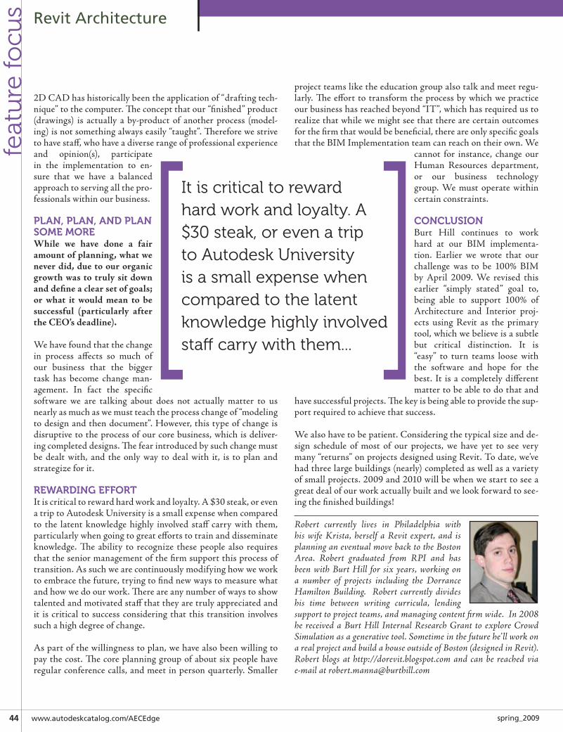
�� www.autodeskcatalog.com/AECEdge spring_2009
Revit Architecturefe
atu
re fo
cus
2DCADhashistoricallybeentheapplicationof“draftingtech-nique”tothecomputer.Theconceptthatour“finished”product(drawings) is actually a by-product of another process (model-ing)isnotsomethingalwayseasily“taught”.Thereforewestrivetohavestaff,whohaveadiverserangeofprofessionalexperienceand opinion(s), participatein the implementation to en-sure that we have a balancedapproachtoservingallthepro-fessionalswithinourbusiness.
PlAn, PlAn, AnD PlAn soME MoREWhile we have done a fair amount of planning, what we never did, due to our organic growth was to truly sit down and define a clear set of goals; or what it would mean to be successful (particularly after the CEO’s deadline).
Wehavefoundthatthechangein process affects so much ofour business that the biggertask has become change man-agement. In fact the specificsoftware we are talking about does not actually matter to usnearlyasmuchaswemustteachtheprocesschangeof“modelingtodesignandthendocument”.However,thistypeofchangeisdisruptivetotheprocessofourcorebusiness,whichisdeliver-ingcompleteddesigns.Thefearintroducedbysuchchangemustbe dealt with, and the only way to deal with it, is to plan andstrategizeforit.
REWARDInG EFFoRtItiscriticaltorewardhardworkandloyalty.A$30steak,orevenatriptoAutodeskUniversityisasmallexpensewhencomparedto the latent knowledge highly involved staff carry with them,particularlywhengoingtogreateffortstotrainanddisseminateknowledge. The ability to recognize these people also requiresthattheseniormanagementofthefirmsupportthisprocessoftransition.Assuchwearecontinuouslymodifyinghowweworktoembracethefuture,tryingtofindnewwaystomeasurewhatandhowwedoourwork.Thereareanynumberofwaystoshowtalentedandmotivatedstaffthattheyaretrulyappreciatedandit is critical to success considering that this transition involvessuchahighdegreeofchange.
Aspartofthewillingnesstoplan,wehavealsobeenwillingtopaythecost.Thecoreplanninggroupofaboutsixpeoplehaveregularconferencecalls,andmeetinpersonquarterly.Smaller
projectteamsliketheeducationgroupalsotalkandmeetregu-larly.Theefforttotransformtheprocessbywhichwepracticeourbusinesshasreachedbeyond“IT”,whichhasrequiredustorealizethatwhilewemightseethattherearecertainoutcomesforthefirmthatwouldbebeneficial,thereareonlyspecificgoalsthattheBIMImplementationteamcanreachontheirown.We
cannot for instance, change ourHuman Resources department,or our business technologygroup. We must operate withincertainconstraints.
ConClusIonBurt Hill continues to workhard at our BIM implementa-tion. Earlier we wrote that ourchallenge was to be 100% BIMby April 2009. We revised thisearlier “simply stated” goal to,being able to support 100% ofArchitecture and Interior proj-ects using Revit as the primarytool,whichwebelieveisasubtlebut critical distinction. It is“easy” to turn teams loose withthe software and hope for thebest. It isacompletelydifferentmattertobeabletodothatand
havesuccessfulprojects.Thekeyisbeingabletoprovidethesup-portrequiredtoachievethatsuccess.
Wealsohavetobepatient.Consideringthetypicalsizeandde-sign schedule of most of our projects, we have yet to see verymany“returns”onprojectsdesignedusingRevit.Todate,we’vehadthreelargebuildings(nearly)completedaswellasavarietyofsmallprojects.2009and2010willbewhenwestarttoseeagreatdealofourworkactuallybuiltandwelookforwardtosee-ingthefinishedbuildings!
Robert currently lives in Philadelphia with his wife Krista, herself a Revit expert, and is planning an eventual move back to the Boston Area. Robert graduated from RPI and has been with Burt Hill for six years, working on a number of projects including the Dorrance Hamilton Building. Robert currently divides his time between writing curricula, lending support to project teams, and managing content firm wide. In 2008 he received a Burt Hill Internal Research Grant to explore Crowd Simulation as a generative tool. Sometime in the future he’ll work on a real project and build a house outside of Boston (designed in Revit). Robert blogs at http://dorevit.blogspot.com and can be reached via e-mail at [email protected]
it is critical to reward hard work and loyalty. a $30 steak, or even a trip to autodesk university is a small expense when compared to the latent knowledge highly involved staff carry with them...

www.augieaecedge.com ��spring_2009
Revit Architecturefeatu
re focu
s
Getting oriented with Revit’s Coordinate system
Most new Revit users that make theswitch fromaCADplatformoftenfindthemselves a bit confused about Revit’s
seemingly invisible coordinate system and un-familiar terminology. On closer inspection onecandrawmanysimilaritiesbetweenthetwo.The
following is an imaginary conversation between an inquisitivenewcomerandaseasonedRevituser…
WHAt ARE sHARED CooRDInAtEs?Alldesignapplicationsneedacoordinatesystemtolocateobjectsinspace.Revit’scoordinatesystemmightseeminvisibleatfirst,but it is there nonetheless! In fact, it is very similar to the oneinAutoCAD.TheProjectCoordinate system inRevit isfixed,justliketheWorldCoordinateSystem(WCS)inAutoCAD.ButwhatistheUserCoordinateSystem(UCS)inAutoCADequiva-lentto inRevit,youmightask?InRevit it iscalledtheSharedCoordinate System, and just like a DWG can house multipleUCS’s,anRVTprojectcanhavemultipleSharedLocations.
WHAt DoEs tHE “MAnAGE PlACE AnD loCAtIons” In My PRojECt Do?ThisdialogisequivalenttotheoneinAutocadwhereyoucanseethevariousnamedUCS’s.EachNamedLocationstoresaunique
SharedCoordinateSystem(auniqueoriginandorientation).Theread-only text box “Angle from Project North to True North”displaystherotationbetweentheProjectCoordinatesystemandtheSharedCoordinatesystemfortheselectedLocation.ProjectNorthistheYaxisoftheProjectCoordinatesystem,whileTrueNorthistheYaxisoftheSharedCoordinatesystemofthecur-rentLocation.(SeeFigure1)
WHERE Is My PRojECt CooRDInAtE systEM oRIGIn?Whenyoustartanewprojectfromthe“default.rte”template,theOriginislocatedsomewherenearthecenterbetweentheeleva-tionannotation.Thereisnovisiblecue,butthereisasimplewaytolocateitaccurately.AssumingyouhaveAutocad,startanewDWGfile,drawa“crosshair”centeredon0,0,0(WCS)andkeepa saved copy handy. Now link this file in a Revit plan view byusingtheOrigintoOriginoption.ThiswilllineuptheWCSofthisDWGtotheProjectCoordinateSystemorigin.The“cross-hair”intheDWGmarkstheoriginandorientationoftheProjectCoordinateSystem.Youcanmarkitwithsomereferenceplanes,pinthemtopreventunwantedshifting,andthendeletethelink.Rememberthatthiscoordinatesystemisunmovable;theoriginandorientationarefixed,justliketheWCS.Youcoulddothisin
➲
Figure 1: Manage Place and Locations
by: David Baldacchino

�� www.autodeskcatalog.com/AECEdge spring_2009
Revit Architecturefe
atu
re fo
cus
youroffice’sprojecttemplatessoeveryonecaneasilyidentifytheProjectOrigin.(SeeFigure2)
WHERE Is My sHARED CooRDInAtE systEM oRIGIn?Whenyoustartaprojectfromthedefaulttemplate,youwillfindthat there is already a location called “Internal”. In contrast toAutocad,aRevitprojectalwayshasaLocation,whereasaDWGdoesnotneedtocontainanamedUCS.“Internal”’sSharedco-ordinateoriginandorientationcoincidewiththoseoftheProjectCoordinate system. It is important to note that changes to theSharedCoordinatesystemareautomaticallysavedtothecurrentLocation. If your Shared coordinate system has been modifiedand you want to control the location of the Shared origin and
orientation,youcanusethe“SpecifyCoordinatesataPoint”tooloracquirecoordinatesfromtheaforementioned“Origin”DWGwhenlocatedattheProjectorigin.(SeeFigure3)
I’M not FolloWInG WHAt you MEAn By “ACquIRE CooRDInAtEs”. CoulD you ElABoRAtE FuRtHER?TherearetwowaystomodifyaSharedCoordinatesystem.YoucandothatbyAcquiringCoordinatesfromaDWGfile/RVTproject,oryoucanSpecifyCoordinatesatalocation.Typically,wewouldusetheAcquiretoolwhen linking inaDWGsurveyoraSiteRVTproject, afterpositioningandorienting the linkproperly inrelationtothebuilding.Thisprocedure is themost“transparent” and does not require us to be bothered with ori-gin locations.Whenyouacquirecoordinates, thehostproject’sSharedCoordinatesystemisalignedwiththeDWG’sWCSortoaUCSthatRevitrecognizes,ortothelinkedRVTproject’sSharedCoordinatesystem.
I tRIED tHIs But REvIt sAys tHAt It CAnnot ACquIRE CooRDInAtEs FRoM A MoDEl WItH MultIPlE nAMED loCAtIons. WHAt’s HAPPEnInG?IfthishappenedwhenacquiringfromaDWG,thenRevitfoundmultipleUCS’sthatitrecognizesanddoesn’tknowwhichonetouse.YoucanacquirefromDWG’sthathaveonlyonerecogniz-ableUCS.IntheabsenceofsuchUCS,theWCSwillbeusedinstead.Thesamewillhappenwitha linkedRVTprojectcon-tainingmultiplenamedlocations.Inthesecases,youmighthavetomanuallyspecifycoordinatesatapointtolocateyourSharedCoordinateSystem.There is however another way to acquire coordinates in suchsituations.Selectthelink,gotoitspropertiesandatthebottom,clickthat littlebuttonontheright(probablyit issaying“<NotShared>”).Inthe“ShareCoordinates”dialog,clickthe“Change”button and select the UCS or Location you want to record asyourhostproject’sSharedcoordinates.Thenselectthe“Acquire”option and click “Reconcile”. Since Revit is also not capable ofpublishing coordinates from projects containing multiple loca-tions,thistechniquewillhelpyouachievethatgoaltoo.
WHAt’s All tHIs ABout PuBlIsHInG CooRDInAtEs?Acquiringforcesyourproject’ssharedcoordinatesystemtoalignto the link’sUCSorcurrentLocation.Publishingdoes the in-verse: it takes your shared coordinate system and forces yourlink’sUCSorcurrentLocationtoaligntoit.Whenyoupublish,youneedtosavethesechangestoyourlinkthroughtheManageLinksdialog ifyouwanttoretainthem,whichwillmodifythelinkedDWGorRVT.Ifyouforget,Revitwillpresentyouwiththeoptiontodosowhenclosingyourproject.
EARlIER you MEntIonED tHAt REvIt RECoGnIzEs CERtAIn uCs’s In A DWG lInk. HoW DoEs It Do tHAt?RevitrecognizesaUCSinaDWGifthenameisprefixedwith“REVIT60-”.SoforexampleifyounameaUCSas“REVIT60-
Figure 2: DWG file linked using Auto - Origin to Origin
Figure 3: DWG file linked using Auto - Origin to Origin

www.augieaecedge.com �7spring_2009
Revit Architecturefeatu
re focu
s
Site”,RevitwilldisplaythisasaLocationcalled“Site”.If thereare other UCS’s that do not follow this naming pattern, Revitwillignorethem.
WHAt HAPPEns WHEn I usE tHE tool “RotAtE tRuE noRtH”?ThistoolhastobeusedinaplanviewsettoTrueNorthorienta-tion. When you use it, you’re changing the orientation of yourSharedCoordinate’sY (TrueNorth)andXaxes in relation totheProjectCoordinateSystem.ThedefaultrotationpointisyourProjectCoordinateSystem’sOrigin(anotherwayofpinpointingthatorigin!).KeepinmindthatifyourotateaboutapointotherthantheSharedorigin,theSharedoriginwillberelocatedalongthecircumferenceofacirclewithradiusequaltothedistancebe-tweentheSharedoriginandtherotationpoint.WhenyouRotateTrueNorth,theendresultwillseemasifthebuildingturnedinthesamedirectionasyourspecifiedangle,butthemodelgeometrydoesn’tactuallymove.
Imagineyouhave2sheetsofglassontopofeachother:OnthebottomistheSharedCoordinatesystemandontopistheProjectCoordinatesystemandthemodelgeometrytiedto it.Let’ssayyourotate20degreesclockwise.SincetheviewisfixedtoTrueNorth,thebottomlayerdoesn’tmoveandthetoplayer(theProj-ectCoordinatesystemandmodel)rotates20degreesclockwiseinrelationtotheSharedsystem.ButkeepinmindthattheProjectCoordinatesystemisfixed,soinrealitytheSharedCoordinatesystemhasrotatedby20degreesanticlockwise!Thisiswhywhenyou rotate True North in one direction and you have a linkedDWGorRVTplacedbySharedCoordinates,itwillseemtoro-tateintheoppositedirectioninaplanviewsettoProjectNorth.
Ifunlikeme,youdon’tcareaboutunderstandingexactlywhatishappening “behind the scenes”, I suggestyou thinkof this toolas“RotateBuildingwithRespecttoTrueNorth”instead,whichwillhelpyoutobettervisualizetheendresult.
WHAt HAPPEns WHEn I REloCAtE My PRojECt?Whenyouusethistool,you’rerelocating/movingtheSharedCo-ordinate system’sOriginbyacertaindistance inanydirection.ThesameeffectcanbeachievedbyusingtheSpecifycoordinatesataPointtool,whereyoucanalsospecifyadifferentanglebe-tweenProjectNorthandTrueNorth,achievingthesamethingastheRotatingProjectNorthtool.Ifyoupickapointthatisnotthesharedoriginandspecifyadifferentangle,theSharedCoor-dinateSystemwillrotatearoundthatpoint,thusdisplacingtheSharedOrigintoanotherlocationrelativetotherotationpointasexplainedearlier.ThisishardtoseeinaviewsettouseTrueNorth,sotostudythisbehavior,tiletwowindows:onesetwithTrueNorthandonesetwithProjectNorth.Itwillbealoteasiertoobservethisbehavior.
WHAt DoEs tHE oPtIon “oRIEnt to vIEW” Do WHEn I lInk/IMPoRt My DWG?Thisoption isonlyavailablewhen “CurrentViewOnly” isun-checked.When“OrienttoView”isselected,theendresultwill
dependontheactiveview’sorientation.Forthepurposesofthisexample,let’sassumethatTrueNorthis30degreesofftheWestofProjectNorth.
a)IfyoulinkintoaplanviewsettoProjectNorth,theDWGwillbeorientedsotheYaxisisverticalinyourview,regard-lessofwhethertheoptionischeckedornot.Inotherwords,theYandXaxeswillcoincidewiththeProject’sYandXaxes.
b)IfyoulinkintoaplanviewsettoTrueNorth,theDWG’sYandXaxeswillmatchtheSharedCoordinate’sYandXaxes.Inthiscase,theYaxiswillbeverticalinyourview.Iftheoptionisunchecked,thedwg’sYandXaxeswillmatchtheProject’sYandXaxes,whichinthiscasewouldresultinyourlinkbeingrotated30degreestotheEastofTrueNorth.
AnotherwaytothinkaboutthisisconsiderthatmostelevationsdrawnincadareinModelSpaceandusingaPlanorientation,ofthepossible3Dvieworientations inAutoCAD.InaplanviewinRevit,ifyouimportanelevationfileandleavethisoptionun-checkedyourelevationwill“lie”onthefloor.Ifyouimportthisfileintoanelevationviewandleaveituncheckeditwillstill“lie”onthefloor.However,ifyouCheckthisoptionthefilewillnowbeorientedparalleltotheviewand“standup”likeapropereleva-tion.
WHEn I usE tHE sPECIFy CooRDInAtEs At A PoInt, It sHoWs My ElEvAtIon As 4’-0”. WHy Is tHAt?Thishappensmostlywhenpickingsomethinginaplanviewinthehostor linkedproject, and is less commonwithflatDWGlinks.Thetoolisactuallypickinganedgeatthecutplaneofyourview,whichisprobablysetto4’-0”.Togettheexactelevation,usethetoolina3Dviewtobesureyouarepickingthecorrectpoint.
Ohlookatthetime!Thisfeatureisquitecapablebutitdoestakesomegettingusedto.Nexttimearoundwe’lltacklethenewfeaturesinRevit2010aswellascontinueourdialog!Thanksforreading!
David Baldacchino works for SHW Group in Texas where he practices architecture and also helps manage their BIM implementation effort. He is passionate about Architecture & Design, but also cares a lot about the project delivery process. He presented Revit classes at Autodesk University 2008 and they were very well re-ceived. He is currently serving as Product Chair for the Revit community at AUGI. He writes the Revit blog: Do u Revit? I do! Its focus is on the Revit platform, discussing techniques, software issues & bugs as well as sharing tips and discussing BIM topics. He married in 2003 and now he and his wife Lori just recently left on a journey of a lifetime hoping to be able to adopt a child from the Ukraine! Blog Address: http://do-u-revit.blogspot.com/

�8 www.autodeskcatalog.com/AECEdge spring_2009
Revit Architecturefe
atu
re fo
cus
key Requirements for a successful BIM Implementation
readers of AUGIWorld Magazine may befamiliarwithmyseriesofarticlesonRevitArchitectureandRevitStructure.I’mvery
pleasedtobecontributingtothisissueofAUGIAEC Edge. In this article I’ll cover some “best
practices”withRevitArchitecturewhenworkingwithInteriors.
ThefirsttopicI’dliketocoverconcernsaRevitobjectthatyoucan’tseeinmostviews,theRoom.Roomsholdinformationaboutthespacestheydefine.Theypickupbordersfromwalls,floors,ceilings, roofs and user drawn room separation lines. Roomsautomaticallyknowtheirdimensions:beingable tosubdivideadesignbyareaandvolumeputsanimmenseamountofusefulin-formationatyourfingertips.Whetheryourbuildingsaresmallorlarge,relativelysimpleorintenselycomplex,properuseofroomswillenableyoutocollateanddisplayspatialpropertiesandcal-culationsquicklyandeffectively.RoomscombinewiththeColorScheme property of orthographic views (plans, elevations, sec-tions)toletyouplacecolorfillsinstantly.Theabilitytorepresentcopiesofafloorplansidebyside,coloredbydepartment,floorfinishorothervariable--andtochangetheseviewsinrealtime--makesadesigner’sconversationwithclientsorreviewersquickerandmorecomplete.
Therealutilityofroomsappearsnotincoloredviews,butintheprosaicRoomSchedulesyoucansetup inanybuildingmodel,evensmallresidences.Roomschedulesallowyoutosliceanddicethe spatial informationyouhavepainstakingly createdbyplac-ing all those walls. Quantity statistics for floor coverings, wallfinishesandapplieddecorationsareautomaticandreliablewhenyouplaceandschedulerooms.Forcommercialproperties,designfirmscannowconsiderfacilitiesmanagementservicesasapos-siblerevenuestreambecausetrackingroomoccupancyovertimeissoeasy.
Here’smy “bestpractice” tipNo.1:Createa roomschedule inyourprojecttemplatesandfillitinwithroomsnamedaccordingtoyourusualpractice.Evenwiththesmallestresidentialprojectswhereyouwillnotbothertonumberrooms,youwillre-usethesame room names (living, bedroom, bath) over and over again;save yourself some repetitive typing and pick the name of theroomyouareplacinginaprojectofftheavailablelist.Revitwillshowtherooms inthescheduleasNotPlaceduntilyoucreateroomobjectsandassignthem.(SeeFigure1)
Thesecondscheduletocreate,ifyouhaveanysortofroomclas-sificationsystem,isaRoomKeyschedule.Inthisscheduleyoudefineroomtypes,orRoomStyles,thenameRevitwillgivethisschedulebydefault.ThenameyougivetheKeyinaKeyScheduleisavailableasafield inyourregularroomschedule,soyoucanassignakeytoeachroom.TheKeySchedulewillincludeotherfields,suchasfinishes;eachrowisaroomstylethatdefinesfinishvalues.Intheroomschedule,youassignstylestoroomstodriveroomfinishdesignations,whichwillsaverepetitivetypingevenif youhaveonly ten rooms inyourproject. If youdesignofficetowers,hotelsorcommercialspaces,RoomKeyschedulesarenotoptional companions to your room schedules, but the efficientwaytopopulatevaluesthatwillinevitablyrepeat.Onceyoucre-ate“Carpet1”and“Carpet2”asfloorfinishestheywillappearinalistsoyoudon’thavetotypethesamethingoverandover,butpickingseveralvaluesinroompropertyfieldsorineachrowofaschedule issimplyaskingforneedlesserrortocreepin,besidesbeingawasteoftime.(SeeFigure2)
by: Christopher Lay-Fox
➲
Figure 1: Create your room names in an empty schedule, and
assign rooms from the list
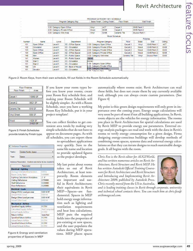
www.augieaecedge.com ��spring_2009
Revit Architecturefeatu
re focu
s
If you know your room types be-fore you know your rooms, createyourRoomKeyschedulefirst,andmaking your Room Schedule willbeslightlysimpler.AswithaRoomSchedule,onceyouhaveaworkingRoomKeySchedule,putitinyourprojecttemplate!
Youcancollectfinishestogetcon-venient area totals by making verysimpleschedulesthatdonothavetoappearondocumentpages.Aswithall schedules,youcanexport these
tospreadsheetapplicationsvery quickly. Save to thesamefilenameandlocationto provide updated figuresastheprojectdevelops.
Mylastpointaboutroomstakes us out of RevitArchitecture, at least tem-porarily. Room elementsare important and use-ful in Revit Architecture;their equivalents in RevitMEP—Spaces--are fun-damental. Spaces in MEPholdenergyusageinforma-tion such as lighting andventilation requirementsand heat loss calculations.MEP puts the requiredfieldsintothepropertiesofpre-existingornewspaces,andtheuserpopulatesthevaluesduringMEPopera-tions. MEP places spaces
automatically where rooms exist. Revit Architecture can readthesefields,butdoesnotcreatethembyanycurrentlyavailabletool, although you can always create custom parameters. (SeeFigure4)
Mypointisthis:greendesignrequirementswillonlygrowinim-portance over the coming years. Energy usage calculations willverysoonbepartofmostifnotallbuildingapplications.InRevit,roomobjectsarethevehiclesforenergyinformation.TheroomsyouplaceinRevitArchitectureforspatialcalculationsareusedby Revit MEP to provide energy use parameters. External en-ergyanalysispackagescanreadandworkwiththedatainRevit’srooms to verify energy consumption for a given design. Firmsdesigning energy-conscious buildings will develop methods ofcombiningroomspaces,systemsdataandexternalenergycalcu-lationssothattheycaniteratedesignstoreachsustainabledesigngoals.Itallbeginswiththeroom.
Chris Fox is the Revit editor for AUGIWorld, and has written numerous articles on Revit Ar-chitecture, Revit Structure and Revit MEP. He has written Autodesk Official Training Course-ware for Revit Architecture and Revit Structure and Introducing and Implementing Revit Ar-chitecture 2009, published by Autodesk Press. Chris recently moved from the US to Australia, and is leading training classes in Revit through corporate, university and technical school contacts there. You can reach him at [email protected].
Figure 2: Room Keys, from their own schedule, fill out fields in the Room Schedule automatically
Figure 3: Finish Schedules
provide totals by Finish type.
Figure 4: Energy and ventilation
properties of Spaces in MEP

�0 www.autodeskcatalog.com/AECEdge spring_2009
Revit Architecturefe
atu
re fo
cus
A tutorial for line Based Families
this short tutorial is intended to introduceyou to the Detail Component Line BasedFamily.Itwillshowyouhowtomakeyour
own “arrow” that can be used to indicate a slop-ingslab,astair“down”arroworperhapsasimpleleader without text. Keep in mind that thereare many practical examples of line based detail
componentfamiliesinthestocklibrariesofmetricandimperialDetailComponents.
Let’sgetstarted!
Therearetwofamilytemplatesfor“2pick”familiesorotherwiseknownasLinebasedFamilies(similarforImperialcontent).
• MetricDetailComponentlinebased.rft• MetricGenericModellinebased.rft
Inadefault installationofRevit these reside inC:\DocumentsandSettings\AllUsers\ApplicationData\Autodesk\RAC2009\MetricTemplates
MetricDetailComponentlinebased.
1)Filemenu→New→Family→ MetricDetailComponentlinebased.rft(SeeFigure1)
2) Settings menu → Family category and Parameters → DetailItems→Youcan’tchangethis.ThishowRevitknowswhatcategorytoputtheobjectunder.Wheneveryoustartanewfamilyyouhaveasecondchancetoassignthecorrectcategorywiththisdialog.
3)DesignBar→ FamilyTypes→ ClickNewtoaddatleast1newType–ifyoudon’tdothis(SeeFigure2)yourfamilymaynotupdateproperlywhenreloadedintoaProject.(SeeFigure3)
by: Toby Maple
➲
Figure 1: Choosing a Family Template
Figure 2: Checking the Family Category Assignment
Figure 3: Add a new Family Type

www.augieaecedge.com �1spring_2009
Revit Architecturefeatu
re focu
s
NotethatyoucannotdeleteorrenametheLengthparameterasithasbeenlockedoutbythedevelopers.
4)ClickOK
5) Settings menu → Object styles - Add your Company’s pre-defined Object Styles before you Load this into any Project!!!Otherwiseyouwillendupwithunusedsub-categories.Let’susethesubcategory“ARROW”.ClickOK
6)SketchusingReferenceLINEStomakecontrollingthearrowheadanglepossible.ReferenceLineshaveactualendpointsthathonourtheirlocationwhereasReferencePlanesdonot.AlwaysuseReferenceLinestodefineAngularconstraints.Adddimen-sionstocontroltheanglewithinthefamily.
7)AddAngulardimensionsbetweenthenewReferencePlanesand theexistingReferencePlane.Clickon “Label”on theOp-tionsBarandselectAddParameter.
8)TheParameterpropertiesdialogappears.(SeeFigure7)
Name:“ArrowHeadAngle”Group:Dimensions(ThisiswhereitwillappearinthepropertiesdialogboxintheProject)Choose“Type”,not“Instance”(ThismeansallFamilytypesofthesamefamilywillusethisparameter)
9) Testyourwork!It is importantto“flex”thefamilytomakesureitworksBEFOREaddinganymoregeometryorlinework.(SeeFigure8)Changetheangleifitworksmoveahead,other-wisefigureoutwhatwentwrongnow.It isnofuntobacktrackwhenyouencounteraproblemonlytolearnitwasaminorthingyoudidmanystepsearlier.
Figure 4: Add a object style
Figure 5: Sketching/Adding Reference Lines
Figure 6: Adding Labels/Parameters to Dimensions
Figure 7: Creating the Angle Parameter

�� www.autodeskcatalog.com/AECEdge spring_2009
Revit Architecturefe
atu
re fo
cus
10)Weneedtoaddaparametertocontroltheheadlengthtoo.ADDDimensions(Itisimportanttodimensionfromtheinsidetotheoutside,Revittakesthisintoaccountwhentryingtocon-trolthedimensionparameters.)
11)ApplyLabels toeachdimensionaccordingtothefigure10.ThistimeitisaninstanceparametersoIcancontroleachfamiliesheadlengthindependentlytootherfamilies.(SeeFigure10)
12) Create “family types” so there are several “Angled Heads”withintheonefamily.(SeeFigure11)
a)OpenFamilyTypesDialogagainb)ClickRenamec)RenametheexistingType1to45°d)AddafewmoretypesasshowninFigure12anddon’tforget
tochangetheparameter“ArrowHeadAngle”tomatchyournewtypes.
Figure 9: Dimensions to define Head Length
Figure 10: Define Head Length Parameter
Figure 11: Creating new Family Types
Figure 12: Adding new Angle Family Types
Figure 8: Testing/Flexing the family

www.augieaecedge.com ��spring_2009
Revit Architecturefeatu
re focu
s
TIP: To create a degree symbol for fonts that support it: With Nu-meric Lock enabled on the numeric keypad, press and hold the ALT key and then press 0, 1, 7, and 6 on the numeric keypad. Release the ALT key. You can also copy and paste a symbol from the Windows Character Map application if a degree symbol is part of the font that you are using.
13)TimetoaddthelineworkandconstrainittoourReferenceLinesaswenowknowthesework.Clickon“Lines”fromtheDe-signBarandselect“Arrow”fromtheTypeSelector.RememberwecreatedtheObjectStyleearlier?(SeeFigure13)
UsethePickandLockOption.Youwillalsohavetochangeyourdimension“HeadLength”todimensiontheHeadlineworknottheRefLineinthepreviousstep.FlexthefamilyafewmoretimestomakesureitallworksbyopeningupthefamilyTypesDialogandchangingthenamedropdownandclickingApply.(SeeFigure14)
TIP:Togetthecopyrightsymbol,sameasearlier!TheCopyrightsymbol©codeisALT+0169.
14)Youmaywanttoadda“ControlDoubleArrow”tomakeitabiteasiertoflipinaProject.(SeeFigure15)
15)Savethefamilyandloaditintoaproject,testyourwork!
Congratulations!YourfirstDetailComponentLineBasedfam-ily!Thesearetheessentialstepsforanysuchcontent.RemembertodefinetheReferencePlanesorLinesfirst,thenadddimensionsandparameterfollowedbytesting.Aftertestingprovesyourcon-ceptsareworkingthenaddthelinework!
GoodLuck!
Toby is driven to manage HASSELL’s ongoing implementation of Autodesk Revit globally, as part of their Building Information Modeling (BIM) solution. He has extensive expertise in overcoming challenges in introducing this technology across organizations. As the Revit Systems Manager for Woolworths Limited, he implemented the BIM standards, methodology and workflow, created content, and trained 20 existing personnel as well as 5 external drafting companies (total 100+ people) in these stan-dards. He then worked for AEC Consulting Services implementing & mentoring the use of Revit into many organizations and differing disciplines. He also taught Revit students (through AEC Systems) scheduled training and on-site. Toby is the Group BIM Manager for HASSELL. He manages the Revit system nationally, and specifically BIM as a methodology, not just as a drafting tool. He has 3 children under 3 years old - so nothing fazes him anymore!
Figure 13: Line work using Pick and Lock
Figure 14: Flexing the Family and “Built By”
Figure 15: Adding a Control - double arrow

�� www.autodeskcatalog.com/AECEdge spring_2009
Revit Architecturefe
atu
re fo
cus
Revit in High school Meet two Progressive teachers and their program
WHo ARE tHEy?TheyareGlenStevensonandBillBrownandtheyarefull-time“Drafting”teachersatSantiagoHS.Theythinkthattheirschoolmaybetheonlyone,atthistimeinthestateofCalifornia,thathastwofulltimeteacherslikethem.SantiagoHighSchool
inCorona,CAislocatedneartheI15andI91interchange.Thereareabout4000studentsinthecomprehensivehighschoolthatispartoftheCorona-NorcoUnifiedSchoolDistrict.
ABout tHE PRoGRAMThey put together an Architecture/En-gineering/Manufacturing/ComputerAnimation program that utilizes Au-todesk’ssoftwaresuchasAutoCAD,Revit,Inventorand3DStudioMaxaswellasacouple other products that are not part ofthe Autodesk portfolio. The Corona-NorcoUnifiedSchoolDistrict is very supportiveofIndustrial Technology programs like Engi-neering and Architecture. Greg Lomeli, theirCurriculum and Instruction support at the dis-trictlevel,hasbeenaninvaluablesupporteroftheprogram.Hefacilitatestheacquisitionofalltheex-pensive hardware, software, and training necessary torunaprogressiveEngineeringandArchitectureprogram.
SantiagoStudentsstartoutinacoursewrittenbyGlenandBillcalled“IntrotoEngineeringandArchitecture”.Studentsstart by sketching and board drafting, Yes, using parallelrules and triangles.Bill says, “We feel studentsneed tophysically measure utilizing decimal inch, metric,andarchitecturescalestogetabettersenseofpro-portion.Theyneedtobeabletolayoutdrawings,scaledrawings,projectviews,andletteraccord-ing to industry standards”. Santiago studentsmake blueprints, how very“old-school”, oftheir drawingsand, after a re-
view,havetheopportunitytomakerevisionsiftheyarenotuptoindustrystandards.
Theirgoalistoguideandifnecessarychangethemindsetoftheirstudentssotheyunderstandthatdrawingsmustbecorrect,notclosetocorrect.Ifachangehastobemade,theymakeit!Intheirfirstquarterstudentsdonottouchthecomputer,theyarelearningthephysicalsideofthingsasmentionedbefore.StudentsstartAu-toCADtrainingduringtheir2ndquarter.TheyutilizeAutoCADtodrawmechanicalobjectsutilizingorthographicprojectionanddimension their work using ANSI standards. During their 3rdquartertheyutilizeAutoCADtocreateasetofconstructiondraw-ings.Thestudentsaregivenadesignproblem,asmallresidentialprogram,tosolveandcreatetheConstructionDocuments.During
their4thquartertheyutilizeAu-toCAD and SketchUP
to create 3Dmodels, botha r c h i t e c t u r a land mechanical.
Students com-ingoutof thisfirst
class have a decentskill-set and are ready
for the next step(s) in thecurriculum.
Students that areinterested in pursu-
ing Architectureas a career take
Bill Brown’s
by: Mark Kiker & Steve Stafford
➲

www.augieaecedge.com ��spring_2009
Revit Architecturefeatu
re focu
s
ArchitectureDesignclasses.Revitisusedtocreatetheworkingdrawingsforstudentdesignedwork.Studentsget180-360hoursofRevittrainingandpracticethroughthe1-2yearstheyspendintheArchitectureDesignclasses.
InsPIRAtIon AnD ACHIEvEMEntSix years ago Bill saw aRevit 5.1 workshop atSantaBarbaraCityCol-lege and felt it was thefuture. A month later,ADTwasgonefromhisprogram and Revit wasimplemented.Sincethensome students that havebeen part of this Archi-tecture design programhavewonthelast5Cali-forniaSkillsUSA/VICAstate championships inArchitecture and havebeen in the top 8 in thenationforthelast3yearsinarow.Studentsinthisprogramhaveworkedrightoutofhighschool for Revit-using companies such as Friedmutter Group,WLCArchitectsandHMCArchitectsjusttonameafew.Stu-dents attend AUGIRevit User Groups in Rancho CucamongaandIrvinetonetworkwithprofessionalsandlearnthelatestRe-vittrends.
A stAtE GRAnt Bill recently won a state grant to provide training to teachers,fromthemiddleandhighschoollevelstothecommunitycollegeanduniversitylevels,inCaliforniatoproperlyuseRevitsoftwarethrough 14 monthly workshops. Professional Revit users arecurrently teaching teachers how to use Revit at Santiago HighSchoolonceamonthonaSaturdayfrom8-4.BillrecruitedsomereallyknowledgeableRevitusersfromavarietyoflocalfirmsandconsulting organizations to teach each session. The workshop
topicsincludeSchedules,Families,Massing,Sitework,Structural,Constructiondocumentsand
details, Central files and Work sharing,Graphics, Materials and Rendering,
Integratingother softwareprogramsinto Revit, and Curtain Walls/
Storefronts.Thebestpartistheworkshops are FREE to theteachers!Thegrantalsopaid
forsoftwaretobeginimple-mentationofRevittrainingat Riverside CommunityCollege (RCC). The “ARE
25”architectureclassatRCC-NorcoisnowaRevittrainingclass.Billiscurrentlyteachingtheclass,buthopestoturntheclassovertoaRevitprofessionalnextFall.
EnGInEERInG too! SantiagostudentsalsohaveanexcellentpathwayinEngineering.
GlenStevensontakesthemfromtheIn-trotoEngineeringclasstoanadvancedCAD class that utilizes Autodesk In-ventor to design or reverse engineerand draw parts to industry standards.They also study Design Manufactur-ing where students use Inventor alongwithMasterCAMsoftwaretoproducepartsutilizingCNC(computernumeri-cally controlled) technology. Santiagostudents entering Engineering schoolshaveabigadvantageinthattheyknowhow to graphically communicate theirdesign ideas (with current technology)to industry standards before they stepfootonacollegecampus.
tHE FutuRESantiago’sArchitectureandEngineeringprogramisalwayslook-ingforpotentialemployersofitsgraduatingstudents,aswellastofindexcellentguestspeakers.Theirfundamentalgoalistopre-paretheirstudentsforrealwork.Theystronglyencouragetheirstudentstopursuesummerinternshipswhiletheyareincollegeto gain “real-world” knowledge that will enhance their collegeexperience,andbetterpreparethemtobeproductiveemployeesimmediatelyaftercollege.ForBillandGlen,theirbeliefandef-fort in this program has provided some of the most rewardingmomentsoftheircareers.
Ifyou’dlikemoreinformationabouttheirprogramyoucanreachthemviaemail:
BillBrown:[email protected]:[email protected]
This article was prepared/edited by Steve Stafford from documents provided to AUGI AEC Edge by Bill Brown.
...“we feel students need to physically measure utilizing decimal inch, metric, and architecture scales to get a better sense of proportion....

�� www.autodeskcatalog.com/AECEdge spring_2009
inside track d
epar
tmen
t
the latest autodesk aec related information!
FEAtuRED ItEM - AutoDEsk lABsweb address: http://labs.autodesk.com/A little bit about them in their own words: “Autodesk Labs is home to innovative new technolo-gies and collaborative development. Its mission is to involve you, the customer, in the progress of design technology solutions. We’re not a beta program
(although Autodesk does have an active beta community), or a usability team, because the
technology we work with is too new to be a product. The user feedback that you
provide to Labs is really on product ideas, while they’re still in an early
conceptual stage. The best way to learn about Autodesk Labs
is to start experimenting yourself.”
You can use this address to visit their “About” page:http://labs.autodesk.com/about/
Therearetworecentadditionsspecificallyfo-
cusedonRevitproducts;RevitSTLExporterandRDBLinkToolforRevit.We’llgiveyoutheinformationyouneedheretofindthemthere.
Revit STL ExporterPostedonApril4,2009
BlogPosttitle:Revit STL Exporter now in the labswebaddress:http://labs.autodesk.com/utilities/revit_stl/
What does it do?“It is a proof of concept tool that is intended to be used with the Revit 2010 products. They write, “It is designed to take a 3D Revit building information model and create an STL file that can be used for 3D Printing. We invite you to take it for a spin and see what you think. We look forward to hearing
your feedback”.
by: Stephen Stafford

www.augieaecedge.com �7spring_2009
inside trackd
epartm
ent
RDB Link Tool for Revit - Posted on May 7, 2009BlogPostTitle:RDBLinkforRevitFamilyNoAvailableonAutodeskLabswebaddress:http://labs.blogs.com/its_alive_in_the_lab/2009/05/rdb-link-for-revit-family-now-available-on-autodesk-labs.html
What does it do?Quoted from the Lab’s overview:“The RDBLink tool allows the user to export data from the elements in a Revit project and maintain relationships against data that exists outside of Revit. The tool allows for both import and export of the project data and will allow the user to make changes on the data-base side that affect the data within the project once imported. Also, during subsequent exports of the data to the same database, only data from the project will be affected, so any new fields or tables added to the database for your own purposes will remain intact along-side the newly exported data. The RDBLink import tool provides a grid view of the data to allow the user to make any final edits before import. This grid control also allows the user to create Revit Shared Parameters which will add new fields for those parameters to the database in the related tables. Changes to these new fields within the database will update these Revit Shared Parameters upon future imports.”
AutoDEsk BloGGInG: REvIt AnD BIM RECEnt ADDItIons:The Revit Clinichttp://revitclinic.typepad.comUsingthetagline“PreventativeandRehabilitativeBIMCare”authorsHarlanBrumm,KathrynPoulos,RyanDuellandJeremySmithcontributepoststhatdealwithissuesreportedtothemintheirrolesintechnicalsupportaswellastipstoavoidatriptotheclinicinthefirstplace.
The Building Coderhttp://blogs.autodesk.com/thebuildingcoderUsingthetagline“BloggingabouttheRevitAPI”authorJeremyTammikhasbeenprolificintheinformativepostsaboutusingtheAPIthathasbeensteadilyincreasingwhatispossible.
Inside the Factoryhttp://blogs.autodesk.com/insidethefactoryUsingthetagline“DesigningtheRevituserexperience”authorsTomVollaro,ErikEgbertson,TsvetanTsvetanovandLilliSmithshareinsiderstoriesofthemanymonthsofresearchthatwentintothe2010releasefortheRevitplatform.Theyarealsobeginningtousetheblogasawaytogarneruserinput.
Buildzhttp://buildz.blogspot.comThisblogisnotsanctionedbyAutodeskbutbelongstoZachKron,anarchitecturaldesignerandsoftwareanalystwithAutodesk.Usingthetagline“PracticalNotesonMakingImpracticalThings”Zachhasbeenpostingveryinterestingex-
amplesof“impractical”thingsthathehasmadewhile“proofing”or“testing”thenewmassingcapabili-tiesofRevit2010.
Beyond the Paperhttp://blogs.autodesk.com/be-yond_the_paperUsingthetagline“Advocatingadvancedtechnologiesforbring-ingdesign,review,virtualization,andsimulationinenvironments”authorVolkerJosephsharesinfor-mationregardingtheNavisworks
productlineandAutodeskDesignReview/DWF.
EstABlIsHED:BIM & BEAMhttp://blogs.autodesk.com/bimandbeamUsingthetaglineofsimply“BimandBeam”authorsNicolasMangon,WaiChuandTomCulottacontributepoststhatsupporttheRevitStructureproduct.TipsandTricksaswellasrecentfeatureupdatesorextensionsarefrequentitems.
Inside the Systemhttp://blogs.autodesk.com/inside-the-systemUsingthetagline“TheMEPBIM.Sustainability.NewTech-nology”authorKyleBernhardtsetthestandardforAutodeskRevitbloggerswithhisinitialeffortssupportingtheMEPproduct.HisfrequentinsightfulpostswithsupportingshortvideoshaveyettobeoutdonebyanyotherAutodeskblogger.KylewasformerlytheProductManagerforRevitMEPandhasmorerecentlytakenanewrolesupportingtheproductsthatfocusonsustainabledesignlikeEcotectandGreenBuild-ingStudioinadditiontoRevitMEPusingabroadertitleofIndustryProductManager
It’s Alive in the Labhttp://blogs.autodesk.com/labsUsingthetagline“It’sAliveintheLab”authorScottSheppardasbeenevenmoreprolificthanJeremyorKylewithhisnearlytwoormorepostsadayhabit.Indicative,webelieve,ofthenearlyoverwhelmingnumberofthingstheyareworkingon“Inthelabs”.
Information Compiled from the Autodesk web site: www.autodesk.com by Steve Stafford
...the user feedback that you provide to labs is really on product ideas, while they’re still in an early conceptual stage...

�8 www.autodeskcatalog.com/AECEdge spring_2009
Revit Structurefe
atu
re fo
cus
Growing Revit structure
likeplantingayoungtreeonawarmspringday Revit implementation requires lots ofnurturing in order for it to grow and bear
fruitandforittobecomearobustpartofthede-signprocesswithinyourfirm.
Thisarticlewillfocusonthosestepsthatweretakenbymyfirm,Brandow&JohnstonStructural&CivilEngineerstoaccomplishthis goal. We are five years into our implementation of RevitStructureandnowallsignificantnewprojectsaredevelopedusingBIMtechniques.Wehavecompletedover200buildingsinarealproductionsettinginthepastfouryears.Projectshaveincludedsuchprojectsasmulit-building schoolcampuses, churches,andmid-riseofficebuildings.Wehaveworkedwithprojectsthatusesteel,masonryandwoodastheirprimarymaterial.
InnovationiscrucialthesedaysintheAECfieldasthetechnologyweusesorapidlychangesandevolves.Wegetthat!Webelievethatweenhanceourcompetitiveadvantagethroughouradoptionof the building information modeling process. Of paramountimportancetooureffortistoincreaseourresponsivenesstoourclientsbybettercommunicatingourstructuraldesignintentandanticipating design problems early on during the course of theprojectthroughthebuildingofthevirtualmodel.
While the virtual model is a tremendous visualization tool wecannotaffordtobuilda3Dmodelaloneforonlythatpurpose.WithRevitwekilltwobirdswithonestoneandderiveboththevisualization benefits and the construction documents at thesametimeandforthesamecost.
When Autodesk bought Revit we were already searching for aproductthatwouldmoveusintothe3Ddesignworld.2DCADreached a peak with Autocad R14, the best 2D CAD releaseever.Themarchtoward3Ddesignthenbeganforusinearnest.Thevenerablethirdpartyadd-onSoftdeskStructuralhadbeenboughtanddeadendedbyAutodesksowewerelookingforare-placement.WestartedtryingtoimplementADT3.3butafterayear-and-a-halfrealizeditwasaverypoorproduct.AtthatpointRevit was bought by Autodesk and we realized now that theyhadtwocompetingproductsintheAutodesklineup.Seeingtheimplications for the future we dumped ADT and immediatelyjumpedontheRevitbandwagon.
Sowhat strategydidweuse to implementRevit? Basicallywekeptour2DAutocadprocessgoingthenstartedasecondparallelprocessinwhichweincreasinglyusedRevit.Ididtheon-boardtutorialsandstartedmyfirstproject inproductioneightweekslater, a largeparking structure. Ipicked the parking structurebecauseIreasonedthatthoughitwaslargeithadaminimumofobjectsthatwouldneedtobemodeled;suchthingsasconcretecolumns,PTbeams,andshearwalls.Nothingtoocomplicatedaboutthem.Ihaveseenotherfirmsstartwithprojectslikealargemedicalcenter.Notsuchagoodideaforafirstproject.
WestartedbyonlydoingaportionoftheprojectinRevit.Thisisagoodstrategytofollow.Youcanfairlyeasilydostructuralplansandelevationssowestartedthere.Typicaldetailsandothersec-tionsweredoneinAutocad.Thisenabledustokeepusingallofourresourcesasefficientlyaspossible. Whileasmallgroupof
Figure 1: Steel dome structure on a large church project
Figure 2: Our first project was this large parking structure. Think of
how many objects need to be modeled
by: Tom Weir
➲

www.augieaecedge.com ��spring_2009
Revit Structurefeatu
re focu
s
enthusiasticReviteersworkedonRevitotherscouldstillbeusingAutocadastheygotuptospeedwithRevit. ThenonthenextprojectwegotalittlefurtherwiththeuseofRevit.Slowlyoverfouryearswemanagedtocompletelytransformourin-houseprocesses.Thatmaximizedtheuseofstaffandsoftwarelicensesaswetransi-tionedfromonetechnologytoitssuccessor.WestayedonthistackforseveralyearsuntilallaspectsofaprojectcouldbecompletedusingRevitStructure.BythenourwholestaffhadlearnedRevittosomedegree.Iwilladmitthatwehavenotgottentoofarintheuseoftheanalyticalmodel.WehadtoomanyproblemswiththeintegrationlinksandfewengineerslearningenoughRevittogetittowork.
Start the project in Revit, partially or not, and if all hell breaksloose,forwhateverreason,simplyexportthewholeprojecttoAu-tocadandcompleteitthere.ThatisagreatreliefvalveforstressedoutdesignteamswhoarestrugglingtotransitiontoBIMbutalsomustadheretoprojectdeadlines.Asfarasweareconcernedproj-ectdeadlinesalwaystrumpsoftwareimplementation.
RememberthatRevitisnotlikeAutocad. When2DCADwasfirst implemented in the 1980’s it was a direct transfer of handdraftingtechniquestocomputeraideddraftingtechniques.ThatisbasicallyalinearevolutionwhilethetransitiontoRevitfrom2DCADisaquantumleap.Ialwaysdiscouragepeoplefromthinking,“IdiditthiswayinAutocad,nowhowcanIdoitthatsamewayinRevit?”Don’tgothere!Thetechniquesaresosignificantlydiffer-entthatyouwillundoubtedlyproducebadresults.
Wedecidedtousea5yearimplementationprocessthatwouldtakeustothepointwherewewouldbeprovidingafullBIMsolutiontoourclients.Thatwouldalsoallowourstafftimetotransitiontothisnewwayofworking. Wefirststartedtrainingthosewhowere enthusiastic, who had some modeling sense, and who had“Stickwithitness”inordertoworkthroughthefrustratinganddif-ficultdevelopmentthatisrequired.Ourtrainingwasdonealmostentirelyin-house.Wehaveweeklytrainingsessionsthatfocusonissuesfromthepreviousweek.Whiletrainingisimportantpeopletendtoneedtobeinarealproductionsettingtocementtheirlearn-ing.Traininghasnonecessitytoit.Inrealproductionyoudon’tgohomeuntilthedeadlineismetsoyouarehighlymotivatedtosolve
yourproblems.Forthatreasonwetrytotaskourassignmentstoeachpersonaccording to their levelofunderstanding. SomeonecanbeaddingbeamtagsintoamodelandinthatwaybecomemorecomfortableintheRevitmodelingenvironmentwhilenothavingtoberesponsibleforthewholeproject.
Wealsohavetofocusalotofattentiononhowmuchtomodel.WhenwestartedusingRevit theextentofourmodelbuildingreflected thescopeofourcontract. Wewerebasicallycreatingtheconstructiondocuments. Onehastobeverycarefulnottomodelmorethannecessaryasit iseasytogetcarriedawayandblowyourfeerightoutofthewindow.
AstheyearspassedwestartedtolookbeyondsimplyproducingdocumentstoprovidingaBIMsolutionforthejob.Weempha-sizethattheintegrityofthemodelmustbemaintainedinorderforatrueBIMsolution.Itiseasytogetintoatimecrunchandstartfakingthingsin2Djusttogetyourjobout.Buttheproblemis themoreyoufakemodelingthe less integrity themodelwillhave.Sowhenyoustartdoingclashdetection,ifyouareworkingwithanarchitectwhoisalsomodeling,orsupplyingthemodeltoadownstreampartnerliketheconstructionteamyoudonothaveanaccuratemodel.
InsummarythisisanexcitingtimeintheAECfield.Theintro-ductionofbuildinginformationmodelingisdrasticallychangingthewaywedoourwork.AtBrandow&Johnstonwebelievewearebetterabletoanticipatedesignproblemswhenwecreateourvirtualmodel,aswellasbettercoordinatewithourarchitectandotherdesignteammembers.Wealsoareabletohelpownersbet-tervisualizetheirproject.Forusthereisnoturningbacktotheoldwaysofworking.Ifyouhavenotdonessoyetitisalsotimeforyoutomakeyourmovetothefuture.
Tom is Associate Principal and Director of BIM & CAD Operations at Brandow & Johnston Inc., a structural and civil engineer-ing consulting firm, where he has worked for the past 28 years. An early adopter and enthusiast of Revit modeling software, he is the founder and co-president of the Los Angeles Revit Users Group. Tom wrote the first AOTC Revit Struc-ture Essentials manual for Autodesk, is a moderator on the AUGI Revit Structure forum, and has taught at Autodesk University for the past four years. He is a frequent speaker and is co-author of Master-ing Revit Structure 2009 published by Wiley Publishing.
Figure 3: Retrofit of NBC Universal’s famous Stage #1 was done
100% in Revit Structure for the new Tonight Show
Figure 4: An entire high school campus with seven buildings

�0 www.autodeskcatalog.com/AECEdge spring_2009
Revit Structurefe
atu
re fo
cus
Integrating Analysis Programs with Revit structure
if you have ever exported a Revit® Structuremodel toananalysisprogram,youmayhavewondered how all of your building data is
transferredfromoneapplicationtoanother.Orperhapsmorelikely,youmayhavewonderedwhy
it wasn’t all transferred correctly on the first attempt! It’s justbeamsandcolumns,sowhyisexportingsuchaproblem?
IntegratinganalysisproductswithRevitStructurepresentsmanyinterestingchallenges. The levelofcomplexitydependsgreatlyon how different an analysis program is from Revit Structure.However, therearemanycommon issues thatallanalysis linksmustaddress.AsasoftwaredeveloperwhoworkedonthelinkbetweenRevitStructureandtheRAMStructuralSystemTM,andiscurrentlyworkingonalinkbetweenRevitStructureandBentley Systems’ STAAD.Pro®, I know first-hand the types ofchallengesfacedbysomeoneattemptingtolinkRevitStructurewithananalysispackage.Let’sexaminejustafewofthem.
vARIAtIons In sCoPENotwostructuralmodelingprogramshandlethesamescopeofstructures.Invariably,whenexportingfromRevit,therewillbesomemodelingconditionintheRevitStructuremodelthatcan-not be modeled in the analysis program. A good analysis linkmustbeabletoanticipateandaddresssuchlimitations.
For example, the Revit Structure model may have multi-storycolumns,wallswithmorethan4nodes,orcurvedbeams–situ-ations which invariably cannot be handled by the one analysisprogramyoudependon.Typicallytheanalysisprogramhassomewaytoapproximatethoseconditionscloselyenoughforanalysispurposes,butthismayrequirespecialmodelingmethods.Howthenshouldtheseconditionsbehandledonexport?
Oneless-than-idealoptionistosimplyignoremembersthatcan-notbeexported“as-is”totheanalysisprogram.Andwhenthereisnogoodwaytoapproximatetheconditionintheanalysispro-gram,thismaybetheonlyoption.
If, however, the developer can anticipate the way the engineerwouldmostlikelymodeltheconditionintheanalysisprogram,the data can be automatically adjusted on export. Multi-storycolumnsarebrokenateachlevel,aboundingrectanglereplacesa wall polygon with more than four nodes, and a curved beamisconverted intoaseriesofbeamsegments. Ofcourse,chang-ing the data to accommodate the analysis program presents itsownchallenges. WenowneedtoconsiderwhichchangeswereintentionallymadeandshouldbesentbacktotheRevitmodel
andwhichweremerelyaccommodationsforanalysisandshouldbeignored.
CHAnGE MAnAGEMEntAnother important issue when developing a bi-directional linkbetweenRevitStructureandananalysisprogramishowtoiden-tifyandmanagechangestothestructure.
Thekeytomanagingchangeistosomehowmaintainalinkbe-tweencorrespondingelementsofthetwoprograms.Identifyingcorrespondingelementsonexportisfairlystraightforward,evenin thecaseofmulti-storycolumnsorcurvedbeams,whereoneRevit element may correspond to multiple analytical elements.The challenge is storing this information so it can be retrievedwhentheRevitmodelisupdatedfromtheanalysismodel.
Revit provides a mechanism for storing data with certain ele-mentsviaaSharedParametersfile.Sincemostanalysisprogramshavesomekindofuniqueidentifierforelements,thatvaluecanbestoredwiththecorrespondingRevitelement.ThevaluecanbeseenintheElementPropertieswindow,andcanbeaccessedpro-grammaticallywhenimportingchangesfromtheanalysismodel.
by: Elizabeth Shulok
➲

www.augieaecedge.com �1spring_2009
Revit Structurefeatu
re focu
s
Unfortunately,therearesomelimitationstosharedparameters.Whiletheyworkfineforelementssuchasbeams,columns,andbraces,theycannotbeassignedtoallcategoriesofelements,suchasmaterials,types(i.e.sectionprofiles),orgrids.Thislimitationmakes itmorechallenging tokeep trackof these items inabi-directionallink.
sECtIon PRoFIlEsNow that we have examinedtwo high level concerns of in-tegrating an analysis programwithRevitStructure, let’s lookat just the issues dealing withsectionprofiles.Althoughthisseemslikeitwouldbeoneofthemost straightforward parts oftheprocess, itcanbethemosttime-consumingtoaddress.
Just considering the standardAISC steel sections, one pro-gram might use a fractionalvalue in thenameofa section(i.e.HSS20X12X5/8)whilean-otherusesadecimalnamingconvention(i.e.HSS20X12X.625).Thisisasimpleexamplethatcanbeovercomewitheitherauto-matic nameconversions or textfiles thatmaponename to theother.
However,doubleangles,oratleastAmericandoubleangles,aremorecomplicated.Inadditiontoastandardnameforthesingleangleused,therearetwootherpiecesofinformationassociatedwithdoubleangles:thespacingbetweenthemandwhetherthelongorshortlegsoftheanglesareback-to-back.
TheAISCshapesdatabaselistsdoubleangleswithallthisinfor-mationencapsulatedinthename:a‘2’atthestartofthenametodenotethatitisadoubleangle;thenthesingleanglename;thespacing,ifany,isdenotednext;andfinally,forangleswithlegsofunequallength,either‘LLBB’or‘SLBB’isappendedtotheend.
AlthoughRevitfollowstheAISCconvention,analysisprogramsvaryintheiruseofnomenclature.ThetwoIhaveworkedwithallowtheengineertoseparatelyspecifytheangleprofile,whethershortorlonglegsareback-to-back,andthespacing.Considering
thatthedouble-anglesectionsinRevitarelimitedtoafixednum-berofspacingvalues(0”,3/8”,or3/4”),imaginethefuntryingtomapdouble-anglesectionsfromananalysisprogramthatallowstheengineertoenteranydecimalvalueforthespacing.
Concrete sections provide their own fun. Remember that wecannot store the analysis pro-gram’s unique ID for a concretesection with the Revit type, sowemustfindanotherwaytode-termine if an element’s size hasbeen changed by the analysisprogram. An obvious solutionforconcretesectionsistousethenameasanidentifier.Sincetheydonothavestandardnameslikesteelsections,wecansimplypasstheRevitnameforthesectiontoouranalysisprogramandassumeifthenamevariesonimport,thesizehaschanged.
However,whatiftheengineerchangedthenameofthesectioninordertocomplywithcompanystandards,withoutchangingtheactualdimensions?OrconsiderSTAAD.Pro,whichnamespris-matic sections automatically based on dimensions, rather thanallowinganametobespecified.Inthiscase,wemustresorttocomparingdimensionsoftheconcretesectionsinordertoiden-tifyachange,orwesimplyupdateeveryconcretememberintheRevitmodel.
Thesearejustafewofthemanyissuesananalysislinkmustan-ticipateandaddress.Asyoucanseefromthisshortintroduction,thereareavarietyofcomplicationsunderlyingwhatmay,atfirstglance, appear tobea simpledata exchange. Thedifferenceofmethodologiesandnomenclaturesmaypresentchallengesforin-tegration,buttheabilitytoleveragebestofbreedmodelingandanalysistoolsisusuallywellworththeeffort.
Elizabeth Shulok is the founder and President of Structural Integrators, LLC, a software company based in Southern California that provides integration tools for the structural en-gineering industry. Prior to starting Structural Integrators in 2007, she spent nearly 9 years as a software engineer at RAM International and Bentley Systems, specializing in interoperability issues. She has worked extensively with the Revit API over the last 4 years. She can be reached [email protected].
... why it wasn’t all transferred correctly on the first attempt! it’s just beams and columns, so why is exporting such a problem?...

�� www.autodeskcatalog.com/AECEdge spring_2009
Revit Structurefe
atu
re fo
cus
Revit Ready - looking BackHow it all started
i am Jamie Richardson, the CAD/BIM man-ager at Ericksen Roed & Associates where Ihaveworked foralmost13yearsnow. Ihave
alwayshadaninterestinCADrelatedprogramsandespecially like theproblemsolving thatcangoalongwithusingthem.Infact,Iamthatguy
that solves a Revit related problem today, than dreams aboutit thatnight tocomeback thenextdaywith3or4more solu-tionsthatarebetterthantheoneIhadthedaybefore.Iknow…mywifetellsmeeveryday.HowdoImakeitstop?Anyways,IwouldliketobrieflytellourstoryabouthowwegotstartedusingRevitStructureatErick-senRoed.
EveryfirmlookingtoimplementRevithopefullyhastheopportunitytohaveatleastoneindividualthathaspassionforthesoftware.Someonewhodoesn’tsit back and wait to be told how thesoftware is going to work or what ittakestorollitouttousers,butsomeonewhowilldigin,findtheanswersand,ifananswercan’tbefound,moveforwardwithwhatmakesthemostsensefromsearchingthroughresourcesavailabletothem.Inourcase,thisindividualhappenedtobeme.Withoutatleastoneuserlikethis,itcanbedifficulttokeepupwiththeeverchangingcapabilitiesofthesoftwareaswellasthenewworkflowscreatedthatneedtobedifferentfromwhen2DCADsoft-warepackagesareused.
OurRevitStructure implementation startedabout4years agowhenIreceivedapostcardinmymailboxannouncingthefirstrelease of Revit Structure. From that point on, things movedforwardratherquickly.ThefirstthingIdidwas gatheruptheexecutivesofthefirmalongwithsomeofourpowerusersfromboththeengineeranddraftingsideandarrangedanonsitedemotoshowthemwhatthebenefitsofusingthesoftwarecoulddoforus.Afterthisdemo,wewereconvincedenoughtobuytwoseatsofRevitStructure.Theonlythingwehadtodothenwasfindthetimetouseit.Atthetimewereallydidnothavethemanpowertoswitchovernordidwehave the timeto train,andofcoursewestillwerenotquitesurewhatweweregettingourselvesinto.WhatwedidhavewasafewofourlargerclientsmakingastrongcommitmenttoswitchfromArchitecturalDesktoptoRevitAr-chitecture. This was probably one of our biggest motivators tocontinueonwithoureffortstoimplementRevitStructureintoourenvironment.Ifwedidn’t,thenweknewthatwecouldpoten-tiallyloseprojectstothosethatwereusingRevitStructure.
Thebiggestobstacle thatneeded tobehurdledduring thefirstfewmonthswasfullyobtainingExecutiveManagementBuy-intousingRevitStructureonourprojects.Yes,wehadpurchasedthesoftware, buthowdoesusing this software changeour currentwork flows or how much information should we be model-ing?Weneededtodiscussthesethingswithotherdesignteammembers during the contract stage of these projects with theunderstanding of what software package we would be using toproduceconstructiondocuments.Ialsosoonrealizedthatvery
fewpeopleoutsideofthedesignteamsweretruly thinkingaboutRevitandsomeactu-allythoughtitwascalledsomethingafrogwould say “Rivit”. I also realized that theknowledge a typicaluser needs to know ismuch different than the knowledge of anexecutive. I quickly continued to educatemyself to further understand the capabili-tiesofthesoftwareaswellasdeterminehowitwouldfitintoourexistingenvironment.
Todothis,Iwasmodelingmycurrentproj-ectsusingRevitStructureoverlunchandafterhoursinadditiontoworkingontheminAutoCADforproduction.Thiswasnotonlyanexcellentwayofself teaching,but itallowedmetoadd3D views to enhance current projects that were being done inAutoCAD.Itisamazinghowmuchhypewasbuiltupwiththosereviewing the documents when they started seeing these viewsshowingupinourset.Weactuallyreceivedcallsfromcontractorstellingushowmuchtheylikedseeinga3Dviewforacomplicatedareaofthebuilding.
Strong efforts were made to contact our clients and those whowereinchargeoftheirRevitimplementationtohelpusgetagoodunderstandingofhowtheywereusingRevit inproductionandhowwecouldcollaboratetogetheronprojects.NetworkinglikethiswithourclientsallowedustoeducatethemaboutwherewewerewithimplementingRevitStructureaswellasshowthemthelimitationsthatwemayhavemodelingcertainstructuralsystems.WithmostofourArchitecturalclientsstartingtouseRevit,weprettymuchdoverightintoworkingonprojectswithuserslearn-ingastheygo.TypicallyanarchitectwillstartoutwithoneRevitprojectwhereweweregettingmultiplerequestsfromvariouscli-entstodotheirprojectsinRevitStructure.Wedefinitelyhadtobeselectiveinchoosingwhichprojectsmademoresensetomodelwiththecurrentcapabilitiesofthesoftware.
As I was educating myself, I tried to educate everybody else. Imade my best attempt at taking everything that I learned andshareditwiththosearoundme.TwiceaweekIhadlittleRevitShowandTellsessions inthe lunchroomwhereIwouldshow
by: Jamie Richardson
➲... if an answer can’t be
found, move forward
with what makes the
most sense...

www.augieaecedge.com ��spring_2009
Revit Structurefeatu
re focu
s
thosethatchosetoattendwhatwasgoingon.Ishowedthestruc-turalmodelsthatIcreatedandwalkedthroughhoweasyitwastocreateschedulestoshowinformationfromthemodel.Thisreallygotalotofattentionandslowlycreatedmoreinterestthroughouttheofficeaswell as started to spread theconversationsoutsidetheofficetoourclients.Withallthisconstantactivityoftalkingabout Revit Structure it was easy to see who were going to beourRevitpowerusers.ThosewhocontinuallyshowedupforourRevitdiscussionsorthosewhocontinuallyaskedquestions,wasagoodindicationthattheyhadaninterestaboutbeingpartofthefirstwaveofuserstolearnandhelpimplementRevitStructure.
tHE REvIt READy PlAnAfter these few months of working on Revit and actually hav-ingaprojectalmostcompleted,wefoundthatwewereproducingprojectsinRevitStructurebutdidn’tquiteknowwhereweweregoingwithitall.Whatwouldbeournextsteps?Wefeltthatwewereeducatedenoughtostartworkingonmoreprojects,butwewouldneedmorepeopleinvolved.Upuntilnowmostofthetimeinvolving education was either while working on a live project,overlunch,atnight,oronweekends.Weneededtogetaplaninplacewhichwouldallownewuserstogetinvolvedandnotexpectthemtoworkextrahourstolearnitall.Wealsoneededtomakesurethat,asacompany,alloftheexecutivesandemployeesun-derstoodwhatourplanwassoastheytalkedaboutRevitwithoutsideclientstheywereeducatedenoughtohavetheconversa-tionsandletthemknowwhatourplanswere.This iswhenwedecidedtoputinplacethe“RevitReadyPlan”.Thisplanbasicallystatedby January1,2007,EricksenRoed&AssociateswillbereadytoproduceasmuchworkinAutodeskRevitStructureasourclients’request.ThiswasourfirstbigcommitmentinsayingthatwewoulduseRevitStructureinlieuofAutoCAD.ARevitprojectwouldbe100%Revit,theuseofAutoCADwouldnotbeacceptablenorwoulditbeasafetynettofallbackon.Wewouldmakeitwork.Wealsodevelopedthe“RoadmaptoRevitPlan”tohelplayoutourinitialplansforimplementationandleteveryoneinthecompanyknowthedirectionwewereheadingandwhy.Wehighlighted things that we thought we needed to focus on andoutlinedabasicmethodfortraining.Theseplansallowedustohaveaclearpaththateveryoneunderstoodaswellasasetgoalforustoachieve.
WoRDs oF ADvICEIwouldliketoshareafewwordsofadvicethatweusedalongthewayasweprogressedthroughoutimplementation.
• Communicateinternally,communicateexternallyandkeepthecommunicationongoing.TheuseofRevitonaprojectisstillnewtoeverybodyandthenewworkflowsinvolvedneedtobecommunicated.
• Findyourkeypeoplethathavethemotivatinginterestandputthematthetopofthepyramidwheretheywillprepareandenforceyourstandards.Ourpyramidstartedoutwithme,wehave2to3userswhoarenowsophisticatedenoughwithRevitwheretheyareourgotopeopleforothersjoiningtheteam.
• We started out with what I call Baby Steps; we only didwhatwefeltwewerecapableofdoingatthetimeandstayedwithinthelimitationsofthesoftware.Ineverreallysetoutonthisjourneywiththeideathatwehadtooutdothenextguy.MymaingoalswerethatIwantedeveryRevitprojecttobeagreatexperience foreveryone involvedthroughout theconstructionteam,westillneededtoissueagoodsetofcon-structiondocumentsonpaperandIwantedthemotivationlevelofthoseinvolvedattheirhighest.
WHERE ARE WE noW?Alothashappenedsincethatinitialyearofgettingupandrun-ning,todaywearemovingfullsteamahead.Wehavedefinitelyreach the point where we no longer ask “should we do this inRevit Structure?” rather we say “why would we not do this inRevitStructure?”.Notcountingamultitudeofmarketing/pre-productionprojects, ournowdozenusers are in theprocessofcompletingour38thprojectproduced100%inRevitStructure.Wearecontinuallyadaptingtotheeverchangingworkflowandare putting more and more information into our models. Ourclient relationships are getting stronger and our collaborationworkflowsarebecomingmoreefficient.Ibelievethatabigpartofoursuccessfulimplementationisthatourexecutivemanagementdidn’tshyawayfromthisthingcalled“Revit”4yearsago.Theyjumpedonboardimmediatelyandhavesupportediteversince.
Jamie D. Richardson is a CAD\BIM Manager at Ericksen Roed & Associates, a Structural En-gineering firm based in Saint Paul, MN. Jamie has been instrumental in the rollout of several versions of AutoCAD as well as the implemen-tation of Revit Structure. He has been an avid speaker on Revit Structure at Autodesk Univer-sity and is a coauthor of the books Mastering Revit Structure 2009 and 2010.

dep
artm
ent
head’s up
�� www.autodeskcatalog.com/AECEdge spring_2009
HEAD’s uP!recent known issues and Problems documented by autodesk and augi members
Hot IssuEs REMInDERsSource - Autodesk Revit Architecture Service & SupportWebAddress:http://usa.autodesk.com/adsk/servlet/ps/index?siteID=123112&id=2956546&linkID=9243099
PRoDuCt kEys FoR AutoDEsk REvIt PRoDuCtsIssue: You want to know what the product key for your Au-todesk®Revit®2010-basedproductis
Solution: Revit2010-basedProductKeys:
• 240B1-RevitArchitecture2010• 241B1-AutoCADRevitArchi-
tectureSuite2010
• 595B1 - AutoCAD Revit Architecture VisualizationSuite2010
• 255B1-RevitStructure2010• 256B1-AutoCADRevitStructureSuite2010• 297B1-RevitMEP2010• 257B1-AutoCADRevitMEPSuite2010• 589B1-AutodeskRevitMEP-B2010
sWItCHInG to PRE-2010, oR “ClAssIC” usER IntERFACEIssue:Youwant toknowifyoucanswitchyouruser interfacebacktothepre-2010userinterface.Solution:Thereisnowaytoswitchyouruserinterfacebacktothe
userinterfaceusedinpre-2010Revitproducts.
by: Stephen Stafford

unABlE to FInD CoMMAnD on RIBBon In AutoDEsk REvIt 2010 BAsED PRoDuCtsIssue:YouwanttoknowwhereRevit2009menucommandsarelocatedonthenewRevit2010ribbons.
Solution:ThereisaspecialguideinRevit2010-basedproductstohelpshowyouwheretools in the2010user interfaceare lo-catedcomparedtopreviousversionsofRevitproducts.Toaccessthistool,clickthearrownexttothequestionmarkbuttonintheupper-rightcornerofthescreenandselecttheWhereismyCom-mandoption.
REsEttInG tHE REvIt ARCHItECtuRE 2010 usER IntERFACEIssue:YouwouldliketoresettheAutodesk®Revit®Architecture2010userinterface(i.e.theRibbon,QuickAccessToolbar,andProjectBrowser)backtotheout-of-the-boxversionandremoveanycustomizationthathasbeenapplied.
Solution: Download a script to automate the repair from thisaddress: http://images.autodesk.com/adsk/files/autodesk_re-vit_architecture_ui_reset.vbs
Youcandothisyourselfaswell,visitthisaddressfortheexplicitinstructions:http://usa.autodesk.com/adsk/servlet/ps/item?siteID=123112&id=13126319&linkID=9243099
knoWn IssuEs - REvIt 2010 onlySource - Autodesk Revit Known Issues Documentation for Revit 2010
WINDOWS VISTA OS WITHOUT SP1 INSTALLED•SomeRevitfunctionality,suchastheAltkeyandright-click-
ingontheRibbon,maycauseunexpectedresultsifServicePack1isnotinstalled.PleaseupgradeyourWindowsVistaOStoincludeSP1.
WINDOWS VISTA OS USING WINDOW AERO COLOR SCHEME
•Sometasksmaycausetheribbontoshowasablankgraphic.Hover over the blank area with your cursor to restore theribbon.
WINDOWS ExPLORER AND REVIT-BASED PRODUCT THUMBNAIL PREVIEWS
•Revit-basedproductthumbnailpreviewsmaydisplay incor-rectly,showingonlyasRevitfileicons,inWindowsExplorerwindows.
ROOM BOUNDING INSTANCE PARAMETERS (PRESENT IN PREVIOUS RELEASES AND STILL IN 2010)
•Currently,notallroomboundingelements(suchasin-placeceilingsandin-placefloors)haveanon/offRoomBoundingparameter.
LARGE DWG IMPORTS (PRESENT IN PREVIOUS RELEASES AND STILL IN 2010)
•DWGimportswithentitiesfurtherthantwomilesapart(af-terscaling)maycauseaccuracy issuesandarenotallowed.VerylargeDWGimportsshouldbesubdividedintosmallerfiles.
•DWGimportswithcoordinates(beforescaling)longerthantendigitsmaybetruncatedtozeroandbecomecorrupted.
AUTOMATIC JOIN GEOMETRy (PRESENT IN PREVIOUS RELEASES AND STILL IN 2010)
•Hierarchal joiningrulesbetweenelementcategoriescannotbechanged.e.g.SlabsalwayscutcolumnswhentheJoinGe-ometrycommandisused.
•AutomaticJoinGeometrydoesnotoccurbetweenWallandSlabcategories.
• It is not possible to disable automatic Join Geometry, butjoinscanbemanuallyun-joined.
•Joinedgeometrymayimpactperformance.
NETWORK DEPLOyMENT (PRESENT IN PREVIOUS RELEASES AND STILL IN 2010)
• The deployment will fail if the computer creating the de-ploymenthasthesameRevitArchitectureversioncurrentlyinstalled.Youmustuninstalltheconflictingversionpriortocreatingthedeployment.
OPENING REVIT ARCHITECTURE fROM A REVIT fILE ICON
•Double-clickingaRevitfileicononlyopensthelatestbuildofRevitArchitecture,ifitisthemostrecentlyinstalledversiononyourcomputer.
KEyNOTING • Currently, Revit Architecture supports only one keynote
tablefileperproject.Userscan,however,combinemultiplekeynotestandardsintothissinglefile.
•Currently, freeunassociatedkeynotesnotsupported,nor iskeynotingofdetail lines(suchasbattInsulation).Youcan,however, keynote a nearby element and move the free endleadertothedesiredlocation.
UN-ENCLOSED ROOM RE-TAG •Currently,ifaroomtagforanunenclosedroomisdeleted,it
isnotpossibletoaddaroomtagbacktotheroomwithoutfirstmakingitaproperlyenclosedroom.Usearoomsepara-tionlinetofixtheroompriortore-tagging.
Editor’s Note: This represents just a selection of issues that are more likely than some of the others to affect users. Please remember to visit the Autodesk Support website for the latest information on docu-mented issues.
Information Compiled from the Autodesk web site: www.autodesk.com by Steve Stafford
www.autodeskcatalog.com/AECEdge ��spring_2009
head’s updep
artmen
t

�� www.autodeskcatalog.com/AECEdge spring_2009
Revit MEPfe
atu
re fo
cus
How to Play nice: sharing revit Models between disciplines
ManyarchitecturalfirmshavebeenusingAutodesk’sBIMplatformRevitArchi-tectureforquitesometime.Asoflate,
consulting engineering firms are joining in theBIMprocessandallpartiesinvolvedhaveakeen
desireandneedtomakegooduseofeachother’s3Dmodels.Asalwaystakingaplungeintoanynewsoftwareplatformisnoteasy.Makingthischange,however,canbeverybeneficial!
Nothing encourages the coordination phone calls like a 3DviewofaroomshowingHVACductsprotrudingintothelivingor working spaces, or sloped sanitary piping piercing a taperedgirder.Solet’stalkabouthowtogetyourmodelstointeractwellwitheachother,producinggood3Ddesignsandcleanconstruc-tiondocuments.
Figure 1: “Ductwork routed through vaulted ceiling space”
First,abitofbackground.InanArchitecture/Engineeringfirm,it’spossibletohaveallthedifferentdisciplinesoperatingonthesamecomputernetworkandworkingdirectlyonthesameRevitmodel.Thiswouldprovidethegreatestdegreeofinteractionandcoordination between the architectural designers and the vari-ousengineeringdisciplinedesigners.Forinstance,a“wallbased”electricalreceptaclecouldbeplacedonawallora“ceilingbased”light fixture in a ceiling as soon as they exist in the common
model.Ifthearchitecturaldesignerdeletedthewall,thiswouldalsodeletethe“wallbased”receptacleinthesamefashionthatawindowinthewallwouldbedeleted.However,evensomeA/Efirmschoosetoseparatetheirmodelsanduseaprocesssimilartotheonebelow.
Workinginaconsultingengineeringfirmwillmeanreceivingthearchitecturalplans fromsomeoneelse.LinkingRevitmodels isvery analogous to xref ’s in AutoCAD. In AutoCAD we wouldreceivethe.dwgfile,stripitofmostofthedata,leavingonlythegeometry we will directly reference and then link this reducedsizefilebymeansofthexrefcommand.
TheprocesscanbequitesimilarwithRevit.Afterreceivingthefile,youcandeleteanyoralloftheviews,Iprefertoleavefloorplanviewsforreference,andthenpurgethefile.Allofthisispurelyforreducingthefilesizeandspeedingupthesoftware.NextyoucreateanewRevitprojectfile,usingatemplate,andlinkthear-chitecturalfileintoyourproject.Theviewsthatweredeletedinthelink,havenoaffectonthe3DgeometryinthemodelleavingitasthereferenceforyourRevitprojectfile.Youwouldthencreateviews,insertequipment,modelandannotatewithmuchthesameworkflowasthearchitecturaldesigners.
Sometime later the architect and other consultants will likelywanttodothesame-linkyourmodelintotheirprojectfiles.Asyou know an MEP consultant’s model contains only MEP ob-jects.Itwillnotcontainwalls,floors,ceilingsandsoon.SowhenanarchitectlinkstheMEPmodelonlyducts,pipes,conduits☺,lightfixturesetc.willbeadded.Thisprocessallowseachoftheprojectteammemberstocompiletheirowncopyofacompletebuilding model. The ability to see how all disciplines interactwithyourdesign is a tremendousbenefit toour industry. Thebestwecoulddobeforethis3Dworkflowwastodevelopsectionsin the “crucial areas”. These non-interactive sections just don’tcompare toaparametric3Dmodelwith liveviews thatupdateautomaticallyasrevisionsaremade.
When there are revisions we all swap models again and if youarecarefulaboutreusingthesamefilenameandplacingitinthesamelocation,theupdatedlinkfilewillloaduponopeningyourproject.Thisbeingtheworkflowbringsusbacktothetitleofthearticle“HowtoPlayNice”.Whataresomegoodmethodsforallinvolvedtomakeourmodelseasierforotherstouse?
by: Jarrod Baumann
➲

www.augieaecedge.com �7spring_2009
Revit MEPfeatu
re focu
s
RulEs to PlAy By: CoMMon oRIGIn PoIntHavingapredictablelinkingpointisessential.Sincethearchi-tect typically goes first, their model will have an origin (0,0,0point)alreadyestablished.Consultantswhencreatingtheirproj-ect file, link in the architect’s building model using the “File >Import/Link>Revit…”commandandthedefault isthe“Auto–CentertoCenter”option.ThisisapoorchoicebecauseRevitisusingacenterpointbasedonthemodeledgeometryinthelinkedfile andyourmodelwillhavedifferent3Dextents, making theswappingofmodelslaterunpredictable.Establishingacommonoriginpointbetweenallteammembersisassimpleasusingthe“Auto–OrigintoOrigin”optioninstead.
Figure 2: Using the Origin to Origin option for linked models
Thisisthebestpracticeforeveryonelinkinginanother’smodelincludingthearchitectwhenreceivingtheconsultant’smodels.
Figure 3: Identify / Set your model origin point
If you have already been misled by the default option, you caneasilyadjusttheoriginpointofyourmodeltomatchthatofthearchitectsusingthe“Tools>SharedCoordinates>SpecifyCo-ordinatesataPoint”commandwithinRevit.
Firstyouwillneedtoknowwherethatoriginisinthearchitec-turalmodel.Simplyusethesamecommandwithinthearchitect’smodel to identifyapointanddo themath fromthere. By theway,formulti-buildingsites,keepyoureyesopenforanupcom-ingarticleregarding“SharedCoordinates”.
DElEtInG oBjECts vs. CHAnGInG tyPEsThis applies to everyone creating elements that will host otherelements,butprimarilytothearchitectcreatingthewalls,floors,andceilings.Whenmakingchangesto thearchitecturalmodelonecommonthingtodoisdeleteanobjectandredrawit.Thisisentirelyreasonableforthearchitectbutcancreatemoreworkforyourconsultants.Asanexample, let’s sayyouareadjustinga room layoutandwant to changeawall location. If youmovethewallandsendyourconsultantstheupdatedmodel,thentheirfacebasedlightfixturesorreceptacleswillusuallymovewithitautomatically.Ifyoudeleteandredrawthewall,however,theseelementswillbeorphanedandwillneedtobere-hostedtothenewwall.Thesamegoesforchangingawallorceilingtype.Selectitandchangethetypeinsteadofdeletingandre-creatingit.
GooD DRAFtInG/MoDElInG stAnDARDsA good case study to illustrate this would be a restroom toiletstall. This isusuallya family in thearchitect’smodelmadeupofseveralothernestedfamiliesandlinework.Thewaterclosetisonenestedfamily,thepartitionsandgrabbarsandsoonareanother,andthedisabledaccessclearanceisusuallydrawnwithsymboliclines.Thevisibilityforeachoftheseitemswillneedtobehandledindependentlybytheplumbingconsultant.
The stall family for instance, might be of the family category“SpecialtyEquipment”whilethewaterclosetisanestedfamilyofthecategory “PlumbingFixture”.Theplumbingconsultantwilltypicallyneedtoshowthestallpartitionsbutwilloftenwanttoturnoffvisibilityofthearchitectsplumbingfixtureandplacehisown.Thisisrequiredbecausetheplumbingconsultantisrespon-sible for making the detailed fixture selection and will need toschedule,annotateandconnectpipingtotheelementwithin
Figure 4: Shared plumbing fixture

�8 www.autodeskcatalog.com/AECEdge spring_2009
Revit MEPfe
atu
re fo
cus
hisownmodel.Thislevelofinterac-tioncannotbeaccomplishedthroughthe linked building model. So, thekey to making this control possiblefor the consultant is to ensure thatthe nested plumbing fixture withinthestallfamilyis“Shared”. Usethe“Settings>FamilyCategoryandPa-rameters”command.
The disabled access clearance lineswill generally have to be turned offentirely inordernot toobscure thepipingsystem inplanview. Theopportunity forpoordraftingstandardsisshownwhenthearchitecturalreviteerdoesn’tuseasingle standardized linestyle torepresentsimilar symbol typesthroughoutaproject.Thismeansthattheplumbingconsultantspendsnumerousadditionalhoursfindingthespecificcategoriesoflinestylestoturnoffinhisconstructiondocumentviews.
lEt tHERE BE lIGHtLightingcomponentsanddesignareanimportantaspectofanyaesthetically pleasing architectural design. It should be one ofour goals as cooperative BIM modelers to reduce the need forduplicateelementswithinthecompiledbuildingmodels.Inthiseffortitwouldbedesirableforthelightingdesignertomodelandplace lightingfixtures in lieuof themresiding in thearchitect’smodel.Thismeansadditionaleffortforthelightingdesignertocreatereasonablyaccurateanddetailed3Dfixturesthatalsocastlightwellwithina renderedview. If this isdone, thearchitectcanusethelinkedlightingmodeltoproduceperspectiveviews,renderedorotherwise,intheirclientpresentationsandconstruc-tiondocuments.
Figure 5: Accurately modeled building elements
GREEn-AlysIsEnergyefficientconstruction is an importantgoal foreveryonein our industry to pursue. BIM has the potential to make thispursuiteasier.Inordertofulfillitspotential,designersfromalldisciplineswillneedtocooperateinthecreationofhighqualitymodels for use in model based analysis. Much of that respon-
sibility rests with the mechanical andlighting engineers. However, a wellconstructed architectural model willmake the task of detailed analysismuchlessdifficult.
In practice this includes things likesimple wall joins, appropriate familycategories and accurately modelingbuildingelements thatarebehindthescenes.Forinstance,unconnectedwallheights should accurately reflect in-tendedconstruction.Bothfullheight
wallsthatextendtothestructureaboveandwallsthatstopattheceilingshouldbemodeledthatway.
We,thecompositeprojectdesignteam,alreadyputatremendousamountofinformationintoour“BuildingInformationModel”,addingabitmoreincreasesitsusefulnessexponentially.
Inclosingitcanbesaidthatgoodconsistentstandardsshouldbeoldhattoallofusbutitseemswealwaysneedtoberemindedwhenstartingsomethingnew.It’sjustliketakinglittleJohnnytotheparkforthefirsttimeandremindinghimtoshareandplaynice.
Jarrod Baumann is currently the BIM/CAD Manager for Design West Engineering, creating standards for and supporting the engi-neering and production staff of the mechanical, plumbing and electrical design departments. He has had much practical experience utiliz-ing AutoCAD since 1995 and Revit MEP® since its release in 2006 on a wide variety of MEP projects in the commercial, educational, medical, and residen-tial fields. Jarrod has led the team tasked with implementing Revit MEP for Design West Engineering as well as assisting major HVAC manufacturers with developing their Revit content for distribution.
...the architect can use the linked lighting model to produce perspective views ...

www.augieaecedge.com ��spring_2009
Revit MEPfeatu
re focu
s
Five steps to success with Revit MEP:the reality
this year our firm was able to identify asignificantly sized project to apply RevitMEP,fromconceptthroughconstruction
documents.Wearea300personplusintegratedAECpractice.Theteamconsistedof10membersofourMEPstaffdedicated to theproject.Although theexperienceprovedchallengingfortheteam,theknowledgewegleanedwasinvalu-able.
The key to delivering projects with this tool is mitigating themostcripplingweaknessofRevitMEP:sluggishmodelperfor-mance.Thisrealitymakesorbreaks thedecision toapply thistool to future projects. The promise of increased productivitywasratherelusiveduringthisprocess,butwewereabletokeepthe team afloat with the proper hardware, consistent training,regularmodelmaintenance,strictmodelingpractices,andstrictsavingpractices.
stEP 1: PRoPER HARDWARE:Overthenextfewyears,thereisagoodchancethatusersonanyRevitMEPprojectwillbenewtotheproduct,andwilllikelynotbeusingthebestmodelingpractices.InaWorksharingEnabledprojectthisnotonlyslowstheindividualdown,butcanhobbletheentireteamwithasluggishmodel.Bythetimeourteamwasworking on construction documents, they were running Dell
5400QuadCoreWorkstationswithVistaBusiness64bit,run-ning 16Gb of RAM, and had ATI Fire GL 256MB GraphicsCards. While throwing hardware at any workflow issue is anexpensivesolution,therealityistheteamwillneedthiswiggleroomiftheyaregoingtostayonschedule.
stEP 2: ConsIstEnt tRAInInG: Consistenttrainingisanabsolutemustinthisworkingenviron-ment.WecontractedwithaRevitconsultantoutofRhodeIslandforaweekof implementation training.Thiswas followedbyaweekofover-the-shoulderdirectprojecttrainingfromthesameconsultinggroup.Duringpreliminarystudiesandschematicde-sign,weofferedin-housebi-weeklytradespecificworkshops.Asnewhireswereaddedtotheteam,thefirmutilizedtheapplica-tionspecialists fromtheITdepartmenttodeliveraweek longin-house version of direct project training. Finally, we utilizedwebconferencingtodeliverone-on-onetrainingonspecifictopicsasneededduringtheentiredurationoftheproject.Theamountof information needed for each team member to be successfulis vast. Even power-users, who can remember all the differentconcepts,willneedtheirmemoriesrefreshedwhenitcomestimetoperformthetaskathand.
stEP 3: REGulAR MoDEl MAIntEnAnCE:Asstatedearlier,inefficientmodelingpracticesareafactoflifeasafirmbeginstransitioningintothisnewapproach.Bysettinguparegularscheduleformodelmaintenancetheteamwasabletokeepahandleonsavingandregenerationtimes.Thismainte-nanceinvolvedaddressingthelinkedcentralfilesfromtheothertrades, the central file itself, the modeling and the size of thecentralfile.
lInkED CEntRAl FIlEs: Aboutmidwaythroughdesigndevelopmentitwasdecidedthatlinkingdirectlytothearchitecturalmodelbecametoocumber-some.Thedesignerswerealreadyspendingafairamountoftimewaiting for each other to save, if the architects were accessing
Image 1: A screen shot of part of our MEP model.
➲
by: Damon Ranieri
consistent training is an absolute must in this working environment. ...

70 www.autodeskcatalog.com/AECEdge spring_2009
Revit MEPfe
atu
re fo
cus
theircentralfile,thattimewastackedon.Thesolutionwashav-ing each trade save a detached copy of their central file to anisolatedlocationtwotothreetimesaweek.ThisalsomitigatedthefrustrationofMEPdesignerswhoweretryingtolayoutar-easthatkeptchangingwitheachSaveToCentral.
CEntRAl FIlE: The model manager began coming in late on Monday so shecouldbeginamaintenanceprocessonthemodelaftertheteamdidtheirfinalSaveToCentralfortheday.Thisincludedacom-pressedSaveToCentral,PurgeAll,andSaveAsoftheprojecttoanewCentralFile.TheactofdoingaSaveAsonaCentralFilerewritesthedatabasewithouttheresidualdatafromdeletedandpurged information, temporary information,andavarietyoferrors.
MoDElInG: Atseveralpointsduringtheprojectthemodelbecamesoslug-gishthatdesignstoppedandalleffortsshiftedtocleaningupthefile.Whenthewarningslistreached200to300warnings,theperformanceoftheCentralFileseemsto
slowdownsignificantly,15to20%byourestimates.TheteamutilizedtheSystemBrowsertomovedevicesandequipmenttothesystemorcircuittheywereultimatelyintendedtobeon.Theprogramisconstantlyre-calculatingsystemtotals,andthelargerthe system, the longer it takes before it moves on to the next.Theprogramconsiders50ormorepartsonanydefaultsystema warning, which compounds the sluggishness. It also spendslongeronopensystems,attemptingtocalculateflowvaluesforafiniteamountoftimeoneachopenconnector,pipeandduct.Capping or terminating open pipes, ducts and removing con-nectors from electrical devices and equipment families whose
circuitswerenotgoingtobemodeledbecameacrucialpartofimprovingmodelperformance.
MoDEl sIzE: Oncethe120Mbfilesizewasreached,adecisionwasmadetobreakup theworkso themodel could return toanacceptablesizeandlevelofperformance.Inthiscase,all2Dwork,details,schedules,etc.werebrokenouttoaseparateCentralFile,andthe3Dmodelwasisolatedintheoriginalcentralfile.Themodelreturnedtothe120Mbsizefairlyquicklyandideasweretossedaroundabouthowtosplitupthe3Dwork.TheMEPfamiliesoften have connections to systems belonging to multiple dis-ciplines, so having separate mechanical, electrical and pipingmodels would become difficult to coordinate. Separating themodeleithergeographicallyorbyHVACzoneswasconsideredmoreseriously.Duetotheprojectschedule,splittingupthe3Dworkneveroccurred.
stEP 4: stRICt MoDElInG PRACtICEs: Anoffshoreconsultantwasusedtobuildmanyofthefamiliesusedatthebeginningoftheproject.Theyweregivenspecificin-structionsonhowwewantedthefamilypartsassembledsothattheregenerationtimeofgraphicscouldbemanaged.Theyweretoldthemajorityofpartsweretobefacebased,non-hosted,ornon-hosted/workplanebaseddependingonthepart.Theywerenottoletany3DentityshowintheCourseDetailLevelviews.
Thefamilies’3Dmodelsweretobeassimplisticaspossible.Onlyenoughdetailtoprovideadequatecollisiondetectionandidenti-ficationwhilecoordinatingwaspermitted.Whenthemodelingshiftedtothemorespecificneedsofthedesignersandtechnicalleadersinvolved,moreofthisworkwasdoneinhouse,applyingthesesamefundamentalrules.Theteambecamefairlyadeptatcreatingandadjusting families, andupdating thesedefinitionsinthemodel.
Image 2: Caption: Just some of the warnings we encountered.
Image 3: A hosted family and its Visibility Settings.
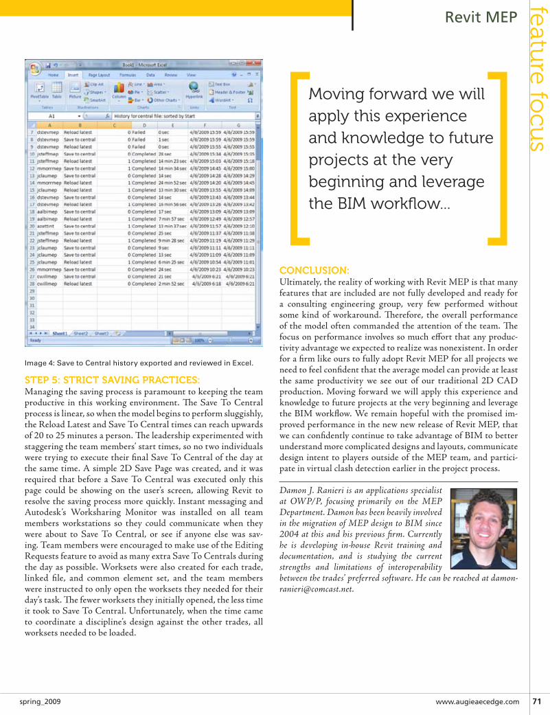
www.augieaecedge.com 71spring_2009
Revit MEPfeatu
re focu
s
stEP 5: stRICt sAvInG PRACtICEs:Managingthesavingprocessisparamounttokeepingtheteamproductive in this working environment. The Save To Centralprocessislinear,sowhenthemodelbeginstoperformsluggishly,theReloadLatestandSaveToCentraltimescanreachupwardsof20to25minutesaperson.Theleadershipexperimentedwithstaggeringtheteammembers’starttimes,sonotwoindividualsweretryingtoexecutetheirfinalSaveToCentralofthedayatthesametime.Asimple2DSavePagewascreated,anditwasrequired thatbeforeaSaveToCentralwasexecutedonly thispage could be showing on the user’s screen, allowing Revit toresolvethesavingprocessmorequickly.InstantmessagingandAutodesk’s Worksharing Monitor was installed on all teammembers workstations so they could communicate when theywere about to Save To Central, or see if anyone else was sav-ing.TeammemberswereencouragedtomakeuseoftheEditingRequestsfeaturetoavoidasmanyextraSaveToCentralsduringthedayaspossible.Worksetswerealsocreatedforeachtrade,linked file, and common element set, and the team memberswereinstructedtoonlyopentheworksetstheyneededfortheirday’stask.Thefewerworksetstheyinitiallyopened,thelesstimeittooktoSaveToCentral.Unfortunately,whenthetimecameto coordinate a discipline’s design against the other trades, allworksetsneededtobeloaded.
ConClusIon:Ultimately,therealityofworkingwithRevitMEPisthatmanyfeaturesthatareincludedarenotfullydevelopedandreadyfora consulting engineering group, very few performed withoutsome kind of workaround. Therefore, the overall performanceofthemodeloftencommandedtheattentionoftheteam.Thefocusonperformanceinvolvessomucheffortthatanyproduc-tivityadvantageweexpectedtorealizewasnonexistent.InorderforafirmlikeourstofullyadoptRevitMEPforallprojectsweneedtofeelconfidentthattheaveragemodelcanprovideatleastthe same productivity we see out of our traditional 2D CADproduction.Moving forwardwewillapply thisexperienceandknowledgetofutureprojectsattheverybeginningandleveragetheBIMworkflow.Weremainhopefulwiththepromised im-provedperformanceinthenewnewreleaseofRevitMEP,thatwecanconfidentlycontinuetotakeadvantageofBIMtobetterunderstandmorecomplicateddesignsandlayouts,communicatedesignintenttoplayersoutsideoftheMEPteam,andpartici-pateinvirtualclashdetectionearlierintheprojectprocess.
Damon J. Ranieri is an applications specialist at OWP/P, focusing primarily on the MEP Department. Damon has been heavily involved in the migration of MEP design to BIM since 2004 at this and his previous firm. Currently he is developing in-house Revit training and documentation, and is studying the current strengths and limitations of interoperability between the trades’ preferred software. He can be reached at [email protected].
Image 4: Save to Central history exported and reviewed in Excel.
Moving forward we will apply this experience and knowledge to future projects at the very beginning and leverage the biM workflow...

7� www.autodeskcatalog.com/AECEdge spring_2009
Revit MEPfe
atu
re fo
cus
Putting the ‘I’ in your BIM content: Revit MEP families that capture design intent
lastyear,atAutodeskUniversity2007,Imetsomeoneinthehotelelevator. HepointedtomyRevitMEPpinandaskedhowitwas
goingusingthesoftware. Isaidthatthereweresomefrustrationsbutweweredoingok(therewas
nopointinbragging,theelevatorridewastooshort).Hisanswertomewas“Yeah,maybewhentheygetmorecontent.”Thenthedoorsopenedandhewalkedout.
Thisideaofwaitingforsomeoneelsetomakemycontentdidn’tseemtofit. I’veworked inseveraloffices thatusedAutoCAD.Notoneofthemusedonlyblocksmadebyothers.Eachfirmhasalwayssetitsownstandardsforwhatisshown,howitlooksandsoon. EvenwhenAutoCADfileswereavailable fromoutside,ineverysinglecasetheygotmodified;cleanedup,paireddown,spruced up, and so on. Why wouldn’t this same idea apply toRevitMEP?
Longstoryshort(toolate,Iknow)–wehaveeithermodeledfromscratchorheavilycustomizednearlyeveryfamilythatisusedinourprojects.Thismeanseverypieceofequipment,airterminal,receptacle,symbol,lightfixture,plumbingfixture,exitsign,pip-ing and duct system family, view reference, annotative tag andlevelhead(didImissany?).
We’vedonethisnotbecausewewanttoworkforRevit,butbe-causewewantthesoftwaretoworkforus.
REvIt Is EAsy?Thereisadifferencebetweensomethingbeingeasyanditbeingsimple. Tobehonest,RevitMEPisn’teitherone. Thereis in-herentcomplexityinanypieceofsoftwarethatintendstomimicbuildingsystemswithenoughaccuracy that it canassist in theengineering calculations, produce 3D models for visualizationandclashdetection, andcoordinated2Ddocumentation. Anyinterfacethatwouldinteractwiththiscomplexmodelisgoingtobedifficulttomaster.Inaddition,thereareanumberofthingsthat we just can’t change. Much of the functionality is simplyhardcodedlike,forinstance,thedisplayoptionsforDuctRiseDropsymbols.(SeeFigure1)
Despitetheseobstacles,therearecertainlyenoughbenefitstobeworthitspursuit.
SohowcanwegetRevitMEPtopayusbackforourefforts,howcanwegetRevittoworkforus?Onewayisbycarefullycrafting
ourfamilies.Theycanbeeasiertouse,provideuserfeedbackandhelpwithcoordinatedconstructiondocuments.Aswegothroughthis‘HowTo’wewillmainlyfocusonthemoreMEP specific parts of the family construction. All disciplinesneedflexible3Dgeometry,sotherearemanysourcesforlearningmoreaboutthat.
“WE . . . ARE . . . FAMIly”Let’sbeginwithanAirTerminalfamily.Thiswillgiveusseveralexamplesofhowwecanputmoreof the ‘I’ inourBIMmodel.Evenifyouarenotanair-headlikeme,thiswillstillbeusefulforlearningthefamilybuildingprinciples.
Oneof themostdetailed AirTerminals suppliedbyAutodeskOOTB(outofthebox) is“SupplyDiffuser-RectangularFaceRound Neck - Hosted.rfa”. This is a face hosted family thatchanges size based on a handful of built in family types. It isappropriately generic so that Autodesk is not unfairly promot-ingonemanufactureroveranother.However,whenitcomestoactualuse, there isnotenoughinformationbuilt in for it tobehelpfulwithdaytodaydesignanddrafting,aswellasbeingmod-eledsomewhatinappropriatelyfordisplayinaproject.
Whenconsideringhowyourmodelisorientedtotheceiling,itisgoodpractice tomodel itprotrudingdownbelowtheceilingplane.Inasurfacemountedframe,thismimicsreality,theframeisbelowtheceiling. Foralay-in-gridceilingtheairterminalistechnicallyabovetheceilingplaneas itsetsontopofthet-bar.
Figure 1: Preset Duct Rise Drop symbol options
by: Joel Londeneurg
➲

www.augieaecedge.com 7�spring_2009
Revit MEPfeatu
re focu
s
Modelingthistechnicallyaccuratecasewouldcausetheproblemoftheairterminalnotbeingvisibleinacameraviewunlesstheceilingwasspecificallycut(thisisnotpossiblewithalinkedar-chitecturalmodel).Also,ifyoumodelittobeexactlycoincidentwiththeceilingplane,Revitwillnotknowthecorrectwaytodis-playeachofthetwocoincidentsurfaces.However,ifyousimplyprotrudeitslightlybelowtheceilingplane,itisvisiblewhenyouexpectittobe.
MostfirmswillwanttobasetheirRevitfamilies,AirTerminalorotherwise,aroundthespecificmanufacturerthatisintheirstan-dard specification. One common Air Terminal manufacturerhasfacesizesthatadjustwitheachnecksizealongwithoptionalframesformountinginlay-in-gridceilings.Youwillwanttosetupyourfamilytypestoreplicateyourofficestandardswithsuchconsiderationsasairflow,noisecriteria,pressuredrop,etc.Anygivenair terminal sizewillhaveaneffectiverangeofFlowthatmeets these standards. Once you make those determinationsfromthemanufacturer’scatalogdata,youcanstorethateffectiverangeineachfamilytype.Asyoucanseefromthescreenshotbelow,MinFlowandMaxFlowarebuiltinparametersforallAirTerminals.Todothis,simplysetupfamilytypestorepresentthesizeyoudesireandinputyourchosenflowrange.Forexample,givena6”necksizeyoumaychooseto limit thedesignflowtobetween0and95CFM.
The Min/Max parameters are for reference only and do notlimittheactualflowsettingwithinRevit,i.e.theywillnotpre-ventyoufromassigningaflowoutsideofthisrange.Youcan,however, use these parameters for your drafters/designers tomakeselectionsfrom.
EMBEDDInG IntEllIGEnCE Youcanalsousetheseparameterstocreateimmediateuserfeed-backwithintheprojectinjust4easysteps!
Gotothe“Ref.Level”viewandcreatesomesortofwarningthatwillnotifythedrafterwhileplacingAirTerminalsintheproject.Youcanusesymboliclinesshapedlikethecommon“NoSmoking”sign.Sothatthisuserfeedbackneverprintsonourconstructiondocuments,setthesymboliclinestypeto<Invisiblelines>
Next,selectthesymboliclines,andassignthevisibilityoftheselinestoanewparametercalled“CFM_Error”
Figure 2: Revit’s display of coincident surfaces
Figure 3: Min/Max CFM parameters
Figure 4: User feedback – Step 1
Figure 5: User feedback – Step 2

7� www.autodeskcatalog.com/AECEdge spring_2009
Revit MEPfe
atu
re fo
cus
Finally assign a formula to the CFM_Error parameter that isactivatedwhentheflowisnotwithinyoursetrangei.e.outsideyourcompanystandard. NotethatthecurrentFlowsettinginthescreenshotisgreaterthantheMaxFlowparameter,causingtheboxtobechecked.
Once you have set the Min and Max flow parameters for yourvariousAirTerminal family types,youcan thenplace them inyourproject.Thisexampleshows3familytypesizes.Currentlyallthreesizesshowthesameflowrate,however,thisisbelowtheminimumflowsettingsforthetwolargersizefamilies.The“NoSmoking”symbolisonlyvisiblewhenyoueitherselectorhoverovertheincorrectlysizedfamily.
What have you accomplished by this basic process? You havenearlyeliminatedtheneedtokeepthemanufacturer’scatalogonyourdeskbecausemostoftherelevantdataisstoredinthefam-ily.Thereisalsolessworkrequiredfortheengineer/designertoconveythedesigntothedrafters.Fortypicalsituationsonlythe
location and air flow need to be identified. The size of an AirTerminal can be determined with the assistance of the family.Fornon-typicaldesigns,theMin/Maxdoesnotpreventyoufromspecifyingoutsidethatrangewhenyouwantto.
ContRollInG GEoMEtRyAnotherfeatureyoumightliketoaddisabetterdisplayofthelay-in-gridpanel.Todothiswewillonceagainbelinkingourge-ometrytoflexibleparameters.Whatweareaimingforisagooddisplayofthe24”x24”panelina3Dview,aswellasinplanview.First,let’srevisittheextrusionthathangsbelowtheceilingplane.Intheimageabove,itisjustpeggedtotheedgeofthefacesize.Amoreaccuratedisplayshouldshowitabout2”largerthanthefacesize forasurfacemountframeandafixed24”x24” forthegridceilingframe.Tosatisfybothofthesesituations,youwillneedtodimensionthelengthandwidthoftheextrusionandlabelthatparameter“Frame_Size”.Mypreferredmethodforkeepingthisextrusioncenteredisbyusingadimensiontothecenterreferenceplanes,withaformuladrivingittobehalfthesize.
YouwillalsoneedaparametertosettheAirTerminalaseithersurfacemountorgrid.Tocreatethisparameter,usetheaddbut-ton in the family types dialog box, name it “T_Bar”, discipline“Common”,type“Yes/No”.Itcanbeeitherinstanceortypede-pendingonyourpreferenceforselectingitwithinaproject.Onceyouhaveboththeseparameters,useaconditionalstatementtoeither drive the frame size to be 2” larger than the face or 24”independentof the face. Asyoucan see fromthe images, this“Yes/No”parameterdrivesthedimensionalparameterswhich,inturn,drivesthemodelgeometry.
Figure 6: User feedback – Step 3
Figure 7: User feedback – Step 4
Figure 8: Flexible model geometry

www.augieaecedge.com 7�spring_2009
Revit MEPfeatu
re focu
s
JustlikeRevitMEPasawhole,craftingfamiliesmaynotbeei-thereasyorsimple.However,aftersometimeisspentincarefulcreation,usingthesefamiliesinyourprojectscanbeboth.
Joel Londenberg is currently a Revit Project Manager for Design West Engineering. He leads their mechanical and plumbing design and supports electrical design for a wide range of projects. These projects are in fields such as retail, commercial, educational, medical, custom homes and multi-family housing, and ranging in size from 3,000 to 300,000 square feet. He has also worked for manufacturers performing equipment design using various 3D software packages. Joel has also been part of the team tasked with implementing Revit MEP for Design West Engineering as well as assisting major HVAC manufacturers with developing their Revit content for distribution.
Figure 9: Flexible model geometry – Option 1
Figure 10:Flexible model geometry – Option 2
Revit technology Conference 2009 – Melbourne Australia
HieveryoneI’mworkingonafewexcitingprojectsandtimeisflyingbysoforgivemybriefinvitebutIwantedtoatleastmakethetimetoletyouknowaboutthiseventandwhatI’mcurrentlyworkingon.
ManyofyouwillalreadyknowabouttheRevitTech-nologyConferencethatisbeingheldinMelbournethisyear(2009)butforthoseofyouwhowanttofindoutmorepleaselookupthefollowinglink:
http://revitconference.com/rtc2009/rtc2009_events.htm
ToregisterfortheRTC2009:https://www.amlink.com.au/secure/ei/getdemo.ei?id=2168&s=_0RW11D6P2
Iwillbespeakingattheeventmyselfagainthisyearandamlookingforwardtosharingmoreofmyexpe-rience.Iwillpostmytalkhandoutonthisblogaftertheeventforanyonewhocan’tmakeit.
18TH Of JUNE, THURSDAy, STREAM 4 (1.4.3) – INDUSTRy PANEL BITTER OR BETTER
Ihavebeeninvitedtobeapartofanindustrypanel.WewillbetalkingaboutthelessonswehavelearntthroughourvariousimplementationjourneyswithMattRumbelow.Ithinkthiswillbeaninvalu-abletalkforanyonewhoisbeginningontheirownimplementationjourneyorformanagementwhoarefindingtheimplementationprocessmoredifficultthantheyhadoriginallyanticipated.Therewillbeawealthofexperienceonthepanel.
19TH Of JUNE, fRIDAy, STREAM 2, (2.2.1) – ADVANCED REVIT fAMILIES AND GENERATIVE COMPONENTS
IhopetoprovidesomeinformationonExternaltools,whatthatallmeansandwhatitmakesavailableforManagementanddrafters.I’vehadtodoalotofresearchtogetsomeoftheinformationandamstillintheprocessoffindingoutmore…I’llalsobetakingacloserlookathowcomponentscanhelpyoucreateastandardisedandautomatedRevitofficesystem.
Hopetoseeyouthere;-)Michelle
ToviewMichelle’sblogonlinegoto:http://bimboombam.wordpress.com/
mic
hel
le lo
uw
blo
g s
po
t

7� www.autodeskcatalog.com/AECEdge spring_2009
Revit MEPfe
atu
re fo
cus
Revit MEP Implementation at CtA Groupa struggle with Promise
revitwasfirstintroducedin2007toourfirmwhenBIMwasthenewexcitingbuzzwordintheA/Eindustry.Itseemedlikeanyone
fortunateenough touseReviton theirprojectswouldsoonbetheindustryleaderforallothers
to follow. However, implementing Revit throughout all of ourofficesanddisciplinesprovedtobeatoughersell.Ourarchitectsandstructural engineersembracedRevit earlyonasRevitAr-chitecture had been available muchlonger.WhenwerolledMEPouttoour engineers in 2008, it was a dif-ferentstory.Theyrealizedthattherewas a major difference in maturitybetweenthesoftwareapplications.
not us!It seemed easy for our engineers tofindreasonsnottogetinvolvedwithRevitMEP.MEP’s savinggracewasthat our firm had made a commit-ment to BIM from the beginning.Withenergyandloadanalysis,alongwith interferencechecking, theengineers realizedwhataben-efit this product would be for our clients. However, a deeplyingrainedengineeringmentalityof“Ihaveaprocessthatworks,whychange”meantthataeasyorseamlessMEPintegrationintoCTA’sintegrateddesignphilosophywouldbeachallenge.
Onourfirstproject,assoonastheengineersenteredthesche-matic design phase, mixed emotions became apparent. Whilemany of them understood the potential MEP could bring, itdidn’tkeeptheirfrustrationlevelsfromrunninghigh.Wefoundouttherewereseveralissuestoovercome.Firstofall,ourengi-neerscamefroma2Dbackgroundthatallowedthemtoeasilycontrol the look and feel of their drawings. Now came RevitMEPandwiththat,theperceptionthatcontrolovertheirdraw-ingswasslippingaway.
tHInGs look DIFFEREnt!Thesymbols,lineweightsandgeneralappearanceoftheirdraw-ingsweredifferentnow.Theengineersfeltthattheclaritytheywere used to was gone from their documents. The temptationtodomuchoftheirworkback inAutoCADprovedtoogreat.Theengineersneededreadability;theyneededthecomfortand
familiaritythatAutoCADgavethem.Althoughtheycontinuedworkingbyportingthingsbackandforthbetweenthetwoprod-ucts,thingsstartedtoclickovertimewithMEP.Theyrealizedthat thepromiseandcontinuityRevitbrought to theirprojectwastoobigtobeignored.Theyalsorecognized,RevitMEPwaskey to CTA’s cornerstone belief in providing the best possibleintegrateddesign.
GEttInG BEttER!In order to get our engi-neers to feel comfortablewith the output of theirdrawings, we had tohave a sit down withthemandlistentotheirconcerns. One item forexample,electricallythesymbols were quite dif-ferent.Thesymbolsthatcameoutoftheboxleftalot open to interpretationin our engineer’s opinion.
Theywerenotusedtoseeingsymbolsforlighting,power,etc.beingdisplayedinthemannertheywere.
Inanotherinstancetheyhadbeenfrustratedbecausetheydidn’trealizethattheycouldgaincontrolofhowthelinkedArchitec-tural and Structural models were displayed. To facilitate ourdiscussionswehadthemprintoutviewsandsheetsandmarkupanythingtheyfeltdidn’twork.WetookthosemarkupsandwentintoourRevitMEPprojectandmadetherequiredadjustments.Whenitcametoaddressingtheirsymbolconcerns,weendedupcreating or editing the families so that the 2D symbology wasexactlywhattheywereusedtoseeing.Insomecasesthisrequiredus to build all new content, in other cases it was just a matterof manipulating what was there. Once we had their buyoff, weimplementedthesechangesinourofficeMEPtemplate.
REFlECtIonItwasn’tuntilwegottheprojectoutthedoor,andhadachanceto sitdownwith theentire team, that thebenefits couldbefullyrecognized.WhileourengineerswerefocusedontheirtasksandtheirownMEPmodel,theydidn’tcompletelyappreciatethebenefititgavetoourownStructuraland
by: Jim Keller
➲...anyone fortunate enough to use revit on their projects would soon be the industry leader for all others to follow ...

www.augieaecedge.com 77spring_2009
Revit MEPfeatu
re focu
s
Architecturalfolks.ThisisimportantbutmoresobecauseCTAisamulti-disciplinefirmandwehavetheaddedmotivationtobebettercoordinatedthanseparatefirmsmighthave.Weenjoya
levelofaccessandcontroloverthewholepro-cessthatseparatefirmsdonot.
It DoEsn’t FIt?Duetothe learningcurvetheengi-neersweregoingthroughwiththeirfirstproject,itwastakingthemlon-ger to produce drawings. However,Revit MEP ended up saving theteam time and money as drawingduplicationwaseliminatedandin-
terference and conflicts becamevisible. For example we hadan instance where our HVACteam could not get all of theirequipment into the basementarea. This was easily visiblewhen they started to layout all
of their ductwork and ransomeinterferencechecking.
Withthewaythestruc-ture was designed atfirst, there just wasn’tenoughroom.Asare-sult of this discovery,our structure teammade some changes,and just two feetwas
addedtothebasementarea. This level of coor-
dination and integrationprovided the opportunity
to easily catch a real prob-lemanditwasmadepossible
andrealbecauseweusedRevit.Once the engineers were able to
focus on the larger picture, theyquicklysawhowRevitMEPcouldplayamuchlargerrollinwhatthey
aredoingtoday.
lookInG AHEADFinally getting a project done thatutilizedalldisciplinesinRevitmadeitamucheasierdecisiontostartthenextproject.Beforewefinishedourfirstproject,theperceptionwasthat
producing documents with RevitMEP couldn’t be done. Oncecompleted, those who stayedwiththeprojecthadsomebrag-gingrights.Sureitwaspainful
at times,butat thispointRevitMEPbecamereal.Ourotherofficessawthedevelopmentandwhatwasaccomplished.Soonthey wanted to be a part of what was going on. They realizedthatbasedonthedirectionwewereheading, if theydidn’tgetonboard,theywouldbeleftbehind.Thosewhobravedourfirstproject came out looking like war heroes. They also broughtcredibilitytothesoftware,andtheycontinuetobeadvocatesforRevitMEP.
While it may still be a small step with Revit MEP and ourengineers, thevaluetheygained inusingRevitwillkeepthemwantingmore.Benefitssuchastheabilitytogeneratethreedi-mensional drawings and integrated design far outweighed thenegatives.IntimeandapplicationourengineersseeRevitMEPplayingalargerollasananalyticaltool.EnergyAnalysis,staticcalculations, loadsanalysis,andcostestimatesare justa fewoftheitemsthatkeepthempressingon.Long-termgoalshavethemworkingonwaystodelivertheintelligentmodeltothecontractorandclientandremovingpaperdocumentsasanecessity.
Jim Keller is an Associate with CTA Architects Engineers and is their BIM Manager. CTA is a 400 person firm that provides A/E services nationally and internationally.
some thoughts about Revit files
SonowwiththenewfeaturebuiltintoRevitthatrecognizesthe“DNA”ofacentralfileandautomati-callycheckstheoptiontocreatealocalfilewiththeappendedusername,addingtheword“central”attheendcouldactuallycauseconfusionwhenyourlocalfileisnamedmyproject_Central_dbaldacchino.rvt.Thisiswhywe’reprobablygoingtostickwithascriptforcreatinglocalfileslikeinthepast,sowecancontrolthenamingconventions,besidessomeotherbenefits.Hopefullywe’llhaveanevenbetteruser-friendlyversion,whichisstillintheworks.
Thatbringsmetothepurposeofthispost:Whydon’tthedevelopersimplementafileextensionsystemthatidentifieswhattypeoffilewe’redealingwith?Perhaps.rvcforCentralfiles,.rvlforLocalfilesandleavethe.rvtfornon-worksetenabledfiles.Thiswouldmakeittotallyclearwhatyou’redealingwith,eliminatingtheneedforarcanenamingconventions.Aunique,easilyidentifiableiconforeachfiletypewouldalsobeaverywelcomeaddition.
ToviewDave’sblogonlinegoto:http://do-u-revit.blogspot.com/
do
-u-r
evit
blo
g s
po
t

ExTENSION MEDIA (to come)

ExTENSION MEDIA (to come)

All architectural design by Hummel Architects PLLC. Photography by William Cox, The Land Group.*HP Cash In & Trade Up promotion is open to U.S. residents only. HP Cash In & Trade Up cash back is provided by mail-in rebate for eligible purchases made during the promotional offer. Time frames for the promotion may vary. Additional restrictions apply. Void where prohibited, taxed, or restricted by law. To access qualifying product options, full terms and conditions, and claim form, visit www.hp.com/go/cashin69. ©Copyright 2009 Hewlett-Packard Development Company, L.P. The information contained herein is subject to change without notice.
AEC_ARC_edge.indd 1 3/13/09 5:31:08 PM