how to extend arduino pwm outputs
TRANSCRIPT

7/26/2019 How to Extend Arduino PWM Outputs
http://slidepdf.com/reader/full/how-to-extend-arduino-pwm-outputs 1/18
How To Extend Arduino PWM Outputs –
TLC5940 Tutorial
Dejan Nedelkovski
February 4, 2016
Ar du ino
In this Arduino Tutorial we will learn how to use the TLC5940 PWM Driver using the Arduino Board.
The TLC5940 is a 16-Channel LED Driver which provides PWM outputs and it’s perfect for extending
the Arduino PWM capabilities. Not just LEDs, but with this IC we can also control servos, DC Motors
and other electronics components using PWM signals.
Basic Features
o VCC = 3V to 5V
o 16 Channels
o 12 bit (4096 Steps) PWM Control
o Driving Capability
– 0 mA to 120 mA (VCC > 3.6V)
– 0 mA to 60 mA (VCC < 3.6V)
o Serial Data Interface
o 30 MHz Data Transfer Rate
o Daisy chaining

7/26/2019 How to Extend Arduino PWM Outputs
http://slidepdf.com/reader/full/how-to-extend-arduino-pwm-outputs 2/18
Daisy chaining is a great feature which means that we can connect multiple TLC5970 ICs together in
series. With this we can extend the Arduino’s PWM capabilities to more than 16 outputs, for example
32, 48, or 64 PWM outputs and still use the same 4 pins used by the Arduino Board as for controlling
one TLC5940 IC.
Arduino and TLC5940 Wiring
For controlling the TLC5940 we need to occupy 4 pins of your Arduino Board. As we will use the
TLC5940 Arduino Library made by Alex Leone we need to connect the IC to the Arduino according
to his library configuration or using the following circuit schematics:
The circuit schematics above is using external power supply for powering the LEDs, but also it can be
connected just using the Arduino VCC itself if the total amount of drawn current doesn’t exceed the
limit of the Arduino (Absolute Maximum Rating, DC Current VCC and GND Pins – 200 mA).
We also need to note that the TLC5940 is a constant-current sink, so the current flow towards the
output pins. This means that when connecting LEDs we need to connect the negative lead (Cathode)
to the output pin of the IC and the positive lead (Anode) to the 5V VCC.

7/26/2019 How to Extend Arduino PWM Outputs
http://slidepdf.com/reader/full/how-to-extend-arduino-pwm-outputs 3/18
We also need 2 capacitors for decoupling and a resistor for controlling the amount of current that flow
through the outputs. The value of the resistor depends on the component that we want to control and it
can be selected using the following diagram from the datasheet of the TLC5940.
So according to the diagram, for controlling LEDs which require 20mA current we need a 2K resistor.
Source Code
Once we download and install the TLC5940 Arduino Library made by Alex Leone we can use his
“BasicUse” demo example for understanding how the control the outputs of the IC.
Here’s a simple code that I made for this tutorial for controlling 16 LEDs using this library. Read the
comments in the code for understanding how the functions works.
1. /*
2. * Arduino and TLC5940 Tutorial - Simple Example
3. * by Dejan Nedelkovski, www.HowToMechatronics.com
4. */
5.
6. #include "Tlc5940.h"
7.
8. void setup() {
9. Tlc.init(0); // Initiates the TLC5940 and set all channels off
10. }
11.
12. void loop() {

7/26/2019 How to Extend Arduino PWM Outputs
http://slidepdf.com/reader/full/how-to-extend-arduino-pwm-outputs 4/18
13. Tlc.set(0,4095); //(Output Pin from 0 to 15,PWM Value from 0 to 4095)
14. // Note: The previous function doesn't activates the output right away. The output will be activated when the Tlc.update()
function will be executed!
15.
16. Tlc.update(); // Activates the previously set outputs
17. delay(1000);
18.
19. // For activating all 16 outputs at the same time we can use a for loop for setting all of them to be set to PWM value of 4095.
Then the Tlc.updata() function will active them all at the same time.
20. for (int i = 0; i < 16; i++) {
21. Tlc.set(i, 4095);
22. }
23. Tlc.update();
24. delay(1000);
25.
26. //The Tlc.clear() function clears all the outputs, or sets the PWM value of all outputs to 0
27. Tlc.clear ();
28. Tlc.update();
29. delay(1000);
30.
31. // This for loop will active all 16 LEDs one by one
32. for (int i = 0; i < 16; i++) {
33. Tlc.set(i, 4095);
34. Tlc.update();
35. delay(200);
36. Tlc.clear ();
37. Tlc.update();
38. delay(200);
39. }
40. }
Controlling more then one TLC5940
For connecting more then one of these ICs in series we can use the same circuit schematics as shown
above. The only difference is that the SOUT (Signal Output – pin 17) of the the first IC needs to be
connected to the SIN (Signal Input – pin 26) of the second IC and so on.

7/26/2019 How to Extend Arduino PWM Outputs
http://slidepdf.com/reader/full/how-to-extend-arduino-pwm-outputs 5/18
As for the programming part we need to make some modifications. In the TLC5940 library folder we
need to modify the tlc_config.h file and change the value of the variable NUM_TLCS to the number
of TLC5940 ICs connected in series and in our case that value is 2. With this done, now we can easily
address all the LEDs from 0 to 31 and use the same method of programming as previously described.
As an example, on the following link, you can check out my DIY LED Heart Photo Frame – Arduino
Project where I use 2 TLC5940 ICs for controling 32 LEDs.

7/26/2019 How to Extend Arduino PWM Outputs
http://slidepdf.com/reader/full/how-to-extend-arduino-pwm-outputs 6/18
DIY LED Heart Photo Frame – Arduino Project
Dejan Nedelkovski
February 3, 2016
In this Arduino Project I will show you how you can make an awesome LED heart photo frame usingArduino. You can watch the following video or read the written article below for more details.
Overview
At first glance it looks like an ordinary photo frame but once you click the switch on the back side it
turns into extraordinary photo frame. Building this Arduino Project is very fun and it can be a perfect
Valentine’s, Birthday or Anniversary present for your loved ones. So let’s get started building it.
Photo Frame Preparation
First we need a simple 18 x 13 cm photo frame and a fiberboard cut to the size of the frame on whichwill make holes for inserting the LEDs. Then we need to draw and print a heart shape with 32 LEDs
which will be used as a pattern. We will make the holes for the LEDs using a drill.

7/26/2019 How to Extend Arduino PWM Outputs
http://slidepdf.com/reader/full/how-to-extend-arduino-pwm-outputs 7/18
Once we are done drilling the holes, we will start inserting the LEDs. We need to insert all LEDs on
the same side, with the Anode or the longer lead pointing outside so that we can bend them and later
solder the Anodes of all LEDs together.
Once we have soldered all LEDs we should check whether all of them are working properly. For thatwe need to connect the positive 5 Volts VCC pin to the Anodes of the LEDs through a 220 Ohms
resistor and using the Ground pin check each of LED whether it will light up.

7/26/2019 How to Extend Arduino PWM Outputs
http://slidepdf.com/reader/full/how-to-extend-arduino-pwm-outputs 8/18
Circuit Schematics
Here’s the circuit schematics of this project and you can find a complete list of components needed for
this project below it . So we will use the Arduino Nano and the two TLC5940 ICs for controlling theLEDs. The TLC5940 is a 16-Channel LED Driver which provides PWM outputs. You can find more
details how to connect and use this IC with the Arduino on my particular Arduino and TLC5940
Tutorial.
Components needed for this Arduino Project
o Arduino Nano – [Get One]
o Ultra Bright Red LEDs – [Get One]
o Switch – [Get One]o Power Jack – [Get One]
o DC 5V >1A Adapter – [Get One]
o 2 x TLC5940 LED Drivers
o 2 x 2K Resistors
o 1uF & 0.1uF Capacitors
*Please note: These are affiliate links. I may make a commission if you buy the components through
these links.
I would appreciate your support in this way!

7/26/2019 How to Extend Arduino PWM Outputs
http://slidepdf.com/reader/full/how-to-extend-arduino-pwm-outputs 9/18
Assembling
Here, first we will insert the IC sockets and the pin headers in place and solder them to the prototyping
PCB so that we can attach the ICs and the Arduino Nano to them. We also need two additional pin
headers with couple of slots for the power, or the 5 Volts VCC and the Ground pins, as well as twocapacitors for decoupling.
We need to be very careful when connecting the components because it can get very messy with that
much wires if we connect something wrong. At this point we need to upload the Arduino code to make
sure that we have connected everything properly.

7/26/2019 How to Extend Arduino PWM Outputs
http://slidepdf.com/reader/full/how-to-extend-arduino-pwm-outputs 10/18
Arduino Code
Let’s take a look at the Arduino code that I have made for this project. So we will use the TLC5940
Library made by Alex Leone. Once we download and install this library we need to modify the
tlc_config.h file and change the value of the variable NUM_TLCS to the number of TLC5940 ICs
connected in series and in our case that value is 2.
7/26/2019 How to Extend Arduino PWM Outputs
http://slidepdf.com/reader/full/how-to-extend-arduino-pwm-outputs 11/18
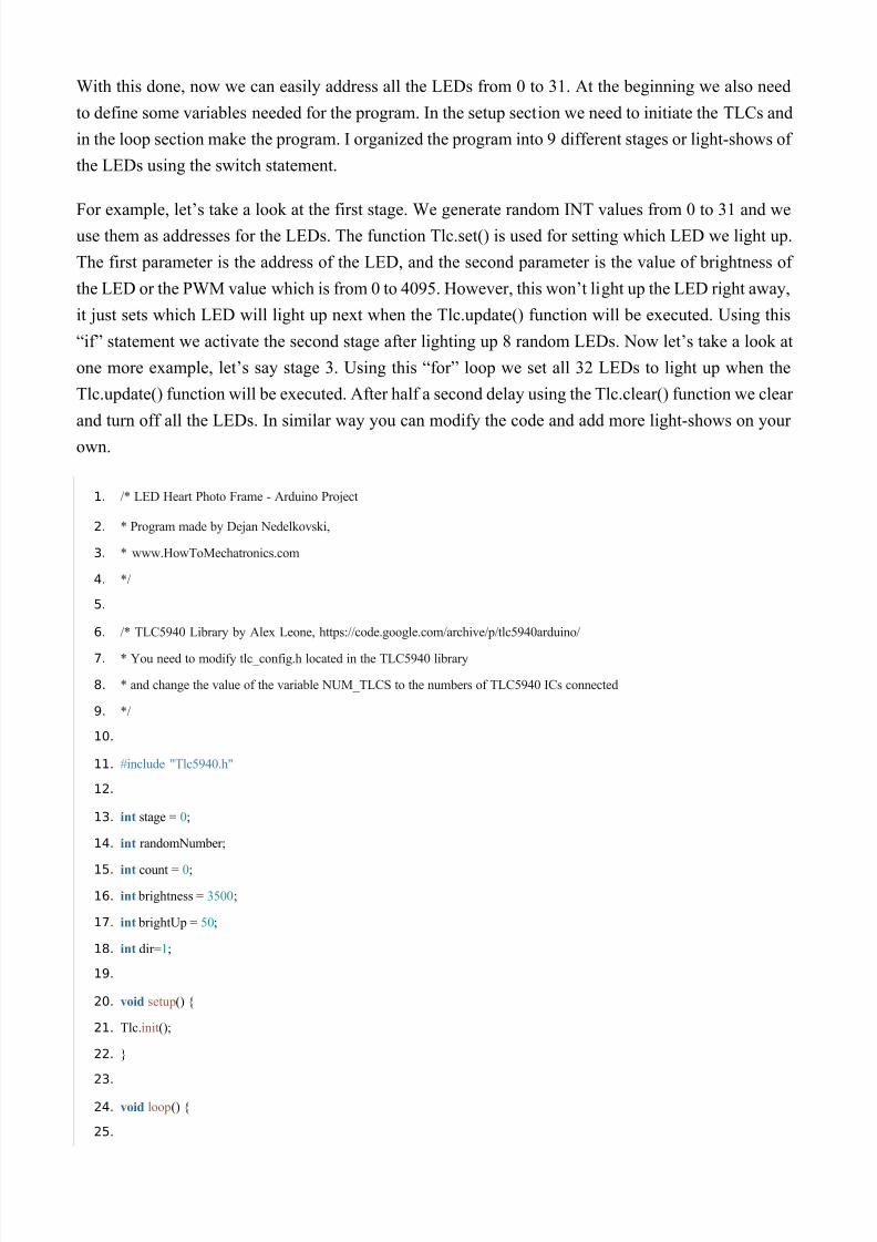
With this done, now we can easily address all the LEDs from 0 to 31. At the beginning we also need
to define some variables needed for the program. In the setup section we need to initiate the TLCs and
in the loop section make the program. I organized the program into 9 different stages or light-shows of
the LEDs using the switch statement.
For example, let’s take a look at the first stage. We generate random INT values from 0 to 31 and weuse them as addresses for the LEDs. The function Tlc.set() is used for setting which LED we light up.
The first parameter is the address of the LED, and the second parameter is the value of brightness of
the LED or the PWM value which is from 0 to 4095. However, this won’t light up the LED right away,
it just sets which LED will light up next when the Tlc.update() function will be executed. Using this
“if” statement we activate the second stage after lighting up 8 random LEDs. Now let’s take a look at
one more example, let’s say stage 3. Using this “for” loop we set all 32 LEDs to light up when the
Tlc.update() function will be executed. After half a second delay using the Tlc.clear() function we clear
and turn off all the LEDs. In similar way you can modify the code and add more light-shows on your
own.
1. /* LED Heart Photo Frame - Arduino Project
2. * Program made by Dejan Nedelkovski,
3. * www.HowToMechatronics.com
4. */
5.
6. /* TLC5940 Library by Alex Leone, https://code.google.com/archive/p/tlc5940arduino/
7. * You need to modify tlc_config.h located in the TLC5940 library
8. * and change the value of the variable NUM_TLCS to the numbers of TLC5940 ICs connected
9. */
10.
11. #include "Tlc5940.h"
12.
13. int stage = 0;
14. int randomNumber;
15. int count = 0;
16. int brightness = 3500;
17. int brightUp = 50;
18. int dir=1;
19.
20. void setup() {
21. Tlc.init();
22. }
23.
24. void loop() {
25.

7/26/2019 How to Extend Arduino PWM Outputs
http://slidepdf.com/reader/full/how-to-extend-arduino-pwm-outputs 12/18
26. switch(stage) {
27. //-----Stage 1
28. case 0:
29. randomNumber = (int)random(0,31);
30. Tlc.set(randomNumber,4095);
31. delay(1500);
32. Tlc.update();
33. if (count >= 8) {
34. stage = 1;
35. count = 0;
36. }
37. else {
38. ++count;
39. }
40. break ;
41. //-----Stage 2
42. case 1:
43. delay(75);
44. for (int i=31;i>=0;i--) {
45. Tlc.set(i,4095);
46. delay(100);
47. Tlc.update();
48. }
49. delay(500);
50. Tlc.clear ();
51. Tlc.update();
52. stage = 2;
53. delay(500);
54. break ;
55. //-----Stage 3
56. case 2:
57. for (int i=0;i<=31;i++) {
58. Tlc.set(i,4095);
59. }
60. Tlc.update();
61. delay(500);
62. Tlc.clear ();
63. Tlc.update();
64. delay(350);
65. if (count > 6) {
66. stage = 3;

7/26/2019 How to Extend Arduino PWM Outputs
http://slidepdf.com/reader/full/how-to-extend-arduino-pwm-outputs 13/18
67. count = 0;
68. }
69. else {
70. ++count;
71. }
72. break ;
73. //-----Stage 4
74. case 3:
75. for (int i=0;i<=15;i++) {
76. Tlc.set(i,4095);
77. Tlc.set(31-i,4095);
78. Tlc.update();
79. delay(70);
80. }
81. delay(50);
82. for (int i=15;i>=0;i--) {
83. Tlc.set(i,0);
84. Tlc.set(31-i,0);
85. Tlc.update();
86. delay(70);
87. }
88. for (int i=15;i>=0;i--) {
89. Tlc.set(i,4095);
90. Tlc.set(31-i,4095);
91. Tlc.update();
92. delay(70);
93. }
94. for (int i=0;i<=15;i++) {
95. Tlc.set(i,0);
96. Tlc.set(31-i,0);
97. Tlc.update();
98. delay(70);
99. }
100. delay(50);
101.
102. Tlc.clear ();
103. Tlc.update();
104. delay(100);
105. if (count > 1) {
106. stage = 4;
107. count = 0;

7/26/2019 How to Extend Arduino PWM Outputs
http://slidepdf.com/reader/full/how-to-extend-arduino-pwm-outputs 14/18
108. }
109. else {
110. ++count;
111. }
112. break ;
113. //-----Stage 5
114. case 4:
115. for (int i=15;i>=count;i--) {
116. Tlc.set(32-i,4095);
117. Tlc.update();
118. delay(5);
119. Tlc.set(32-i-1,0);
120. Tlc.update();
121. delay(5);
122. Tlc.set(i,4095);
123. Tlc.update();
124. delay(5);
125. Tlc.set(i+1,0);
126. Tlc.update();
127. delay(50);
128. }
129. if (count > 15) {
130. Tlc.set(16,4095);
131. Tlc.update();
132. delay(2000);
133. stage = 5;
134. count = 0;
135. }
136. else {
137. ++count;
138. }
139. break ;
140. //-----Stage 6
141. case 5:
142. for (int i=0;i<=31;i++) {
143. Tlc.set(i,brightness);
144. Tlc.update();
145. }
146. Tlc.update();
147. brightness = brightness + brightUp;
148. if ( brightness>=3500) {

7/26/2019 How to Extend Arduino PWM Outputs
http://slidepdf.com/reader/full/how-to-extend-arduino-pwm-outputs 15/18
149. brightUp=-50;
150. ++count;
151. }
152. if ( brightness<=150) {
153. brightUp=50;
154. }
155. if (count > 6) {
156. stage = 6;
157. count = 0;
158. brightness = 3500;
159. Tlc.clear ();
160. Tlc.update();
161. }
162. delay(40);
163. break ;
164. //-----Stage 7
165. case 6:
166. for (int i=0;i<=30;i+=2) {
167. Tlc.set(i,4095);
168. Tlc.set(i+1,0);
169. }
170. Tlc.update();
171. delay(500);
172. for (int i=0;i<=30;i+=2) {
173. Tlc.set(i,0);
174. Tlc.set(i+1,4095);
175. }
176. Tlc.update();
177. delay(500);
178. if (count > 20) {
179. stage = 7;
180. count = 0;
181. }
182. else {
183. ++count;
184. }
185. break ;
186. //-----Stage 8
187. case 7:
188. for (int i=31;i>=16;i--) {
189. Tlc.clear ();

7/26/2019 How to Extend Arduino PWM Outputs
http://slidepdf.com/reader/full/how-to-extend-arduino-pwm-outputs 16/18
190. Tlc.update();
191. delay(2);
192. Tlc.set(i,4095);
193. Tlc.set(i+1,2000);
194. Tlc.set(i+2,1000);
195. Tlc.set(i+3,500);
196. Tlc.set(i+4,300);
197. Tlc.set(i+5,200);
198. Tlc.set(i+6,100);
199. Tlc.set(i+7,50);
200. Tlc.set(i+8,0);
201.
202. Tlc.set(i-16,4095);
203. Tlc.set(i-15,2000);
204. Tlc.set(i-14,1000);
205. Tlc.set(i-13,500);
206. Tlc.set(i-12,300);
207. Tlc.set(i-11,200);
208. Tlc.set(i-10,100);
209. Tlc.set(i+-9,50);
210. Tlc.set(i-8,0);
211.
212. Tlc.update();
213. delay(50);
214. }
215. if (count > 8) {
216. for(int i=31;i>=0;i--) {
217. Tlc.set(i,4095);
218. Tlc.update();
219. delay(50);
220. }
221. stage = 8;
222. count = 0;
223. }
224. else {
225. ++count;
226. }
227. break ;
228. //-----Stage 9
229. case 8:
230. for(int i=31;i>=0;i--) {

7/26/2019 How to Extend Arduino PWM Outputs
http://slidepdf.com/reader/full/how-to-extend-arduino-pwm-outputs 17/18
231. Tlc.set(i+8,4095);
232. Tlc.set(i+7,2000);
233. Tlc.set(i+6,1000);
234. Tlc.set(i+5,500);
235. Tlc.set(i+4,300);
236. Tlc.set(i+3,200);
237. Tlc.set(i+2,100);
238. Tlc.set(i+1,50);
239. Tlc.set(i,0);
240. Tlc.update();
241. delay(50);
242. }
243. for (int i=31;i>=0;i--) {
244. Tlc.set(i,4095);
245. }
246. Tlc.update();
247. delay(10);
248. if (count > 8) {
249. delay(8000);
250. Tlc.clear ();
251. Tlc.update();
252. stage = 0;
253. count = 0;
254. }
255. else {
256. ++count;
257. }
258. break ;
259.
260. }
261. }

7/26/2019 How to Extend Arduino PWM Outputs
http://slidepdf.com/reader/full/how-to-extend-arduino-pwm-outputs 18/18
Final Touch
Once we are done with the programming and know that everything works well, we need to secure the
LEDs to the fiberboard and I did that using a glue gun. Then we need to make a cover box for the
electronics using a glue gun and 4 more pieces of fiberboard cut to size.
What’s left now is to connect the power lines coming from the switch and the power jack which are
inserted in the fiberboard of the photo frame, add the photo, secure the whole box to the photo frame
and we are done!
Here you can watch the complete Demo video of the LED Heart Photo Frame.