how to diagnose a failed t'con board - how to replace …
TRANSCRIPT

T'Con boards
Sony T'Con board
[http://1.bp.blogspot.com/-
pmEww3kZ0oY/UchipaffN_I/AAAAAAAAz1M/agoWIFhtN-o/s1600/imagesCAS13O0K.jpg]
Samsung T'Con board
[http://3.bp.blogspot.com/-
hcs70qDaS7w/UchDpu9EL6I/AAAAAAAAzzc/bRjA6kvIwCw/s1600/samsung+lj94-
03375e+t'con+board.jpg]
DIAGNOSING A FAILED T'CON BOARD
All video inputs received by the video process circuits are handled on a
frame-by-frame basis. The video frames are converted and scaled to 8 to
10 bit RGB information. It is virtually impossible for the video process
circuit to cause a problem on a specific area of the screen. Failures on
this board usually appear as distortions, color level shifts, video level
shifts or noise that involves the entire picture. The T’Con can generate
symptoms that appear to be video process related, but the video process
circuit cannot produce the symptoms of a failed T’Con board circuit.
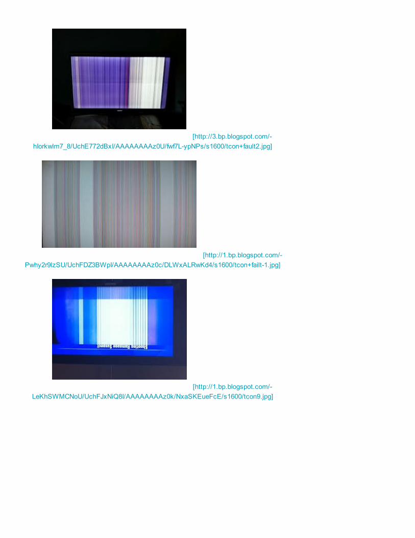
T'CON FAILURES
Failures in the timing control circuits of the T’Con can produce symptoms
of absolutely no video or generate lines and patterns that usually cover all
or a substantial part of the screen. Determining if the T’Con is the cause of
a ‘No Video’ condition is a bit more difficult since there are no indications
on the screen to analyze. Many of the Sony TV models ove the last few
HOW TO DIAGNOSE A FAILED T'CON BOARD -HOW TO REPLACE A T'CON BOARD

years will detect a T’Con that has completely failed. The communications
data between the video process circuits and the T;Con will cease to
communicate, iif the T’Con fails completely. This will cause the TV to shut
down and display a diagnostic code, indicating a failure of the T’Con. Not
all chassis designs have this feature and it is not found on older models.
The typical scenario when this failure arises is for the technician to bring a
video process board to the repair location. It is usually safe to assume that
the problem lies on the T’Con board, if the replacement video board dos
not give a solution to the problem since it is highly unlikely that a
replacement board with the same failure was received. One trick to check
most T’Cons for functionality is to loosen the LVDS connector at the T’Con
while unit is turned ON. Handle the LVDS connector with care and be
certain to fully release the lock tabs. Gently rock the cable in and out of
the connector while observing the screen for any response. Depending
on the chassis, the symptoms of the screen ma be gentle white flashes,
intermittent coloured lines, or a screen full of random patterns. The idea at
this point is to provoke some kind of response on the screen. Another
helpful procedure is to rapidly heat and/cool the T’Con with a hot air
devices or circuit coolant and watch for patterns appear on the screen.
[http://3.bp.blogspot.com/-
RPKc2YnJUlk/UchEwCq3PSI/AAAAAAAAz0E/BvK0b_AOYrI/s1600/tcon+fault+4.jpg]
[http://2.bp.blogspot.com/-
AfQDyS8lW0Q/UchE1kqlzbI/AAAAAAAAz0M/oo279gm3j5k/s1600/tcon+fault-3.jpg]
[http://3.bp.blogspot.com/-
hIorkwlm7_8/UchE772dBxI/AAAAAAAAz0U/fwf7L-ypNPs/s1600/tcon+fault2.jpg]
[http://1.bp.blogspot.com/-
Pwhy2r9lzSU/UchFDZ3BWpI/AAAAAAAAz0c/DLWxALRwKd4/s1600/tcon+failt-1.jpg]
[http://1.bp.blogspot.com/-
LeKhSWMCNoU/UchFJxNiQ8I/AAAAAAAAz0k/NxaSKEueFcE/s1600/tcon9.jpg]

[http://3.bp.blogspot.com/-
WAYo5IhlCCM/UchFOmFu3FI/AAAAAAAAz0s/8NXB9tBwfe0/s1600/tcon6.jpg]
[http://2.bp.blogspot.com/-
XvtgBRaEyTo/UchFTuKDqVI/AAAAAAAAz00/IAU5lrpsS_Q/s1600/tcon7.jpg]
[http://3.bp.blogspot.com/-
QlXzNc10Sdc/UchFbzhH7aI/AAAAAAAAz08/LIowMVEZkIg/s1600/tcon8.jpg]
LVDS cable failures
Although the problem with LVDS cable or connectors can generate
symptoms of T’Con failures this usually tends to be intermittent and
wiggling of the connectors will usually provoke a change in the symptom
on the screen. LVDS cable and connectors have became rather robust
over the past few years. Technicians who damage them cause most
problems and this is generally quite oblivious upon close examination.
LVDS CABLE

[http://2.bp.blogspot.com/-
lPNy_b5_jGU/UchELW1YYDI/AAAAAAAAzzk/0NCpWknHaWE/s1600/lvds.jpg]
[http://4.bp.blogspot.com/-IzJ-
QC80Cpw/UchEUC2DSJI/AAAAAAAAzzs/BTFi9s3v5-g/s1600/lvds+cable.jpg]
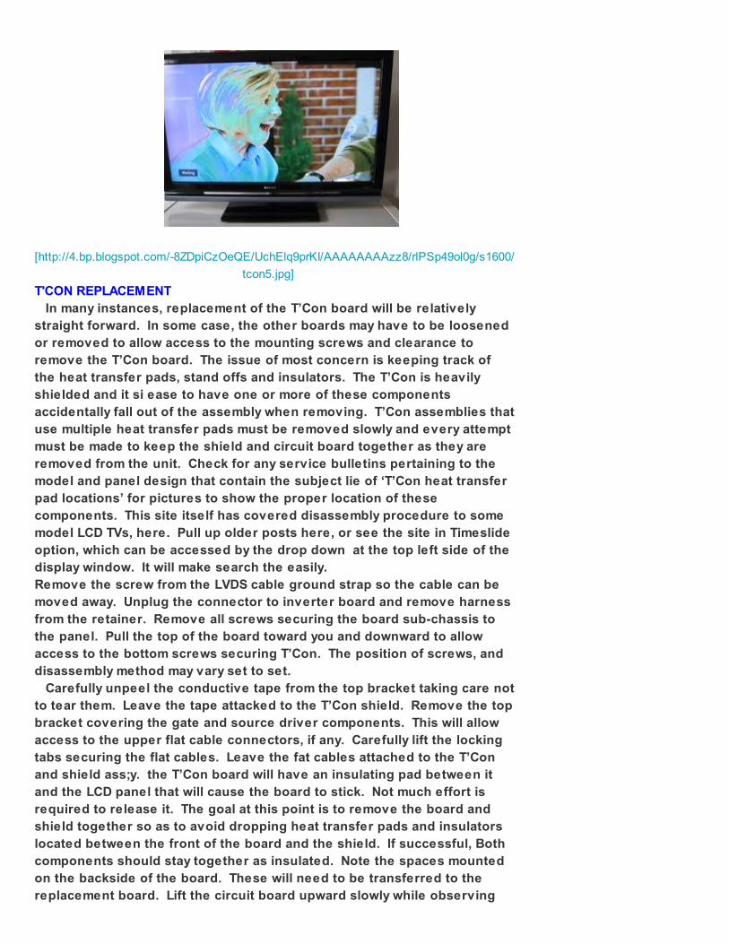
LCD panel failures
Some LCD panel failures could possibly mistaken for T’Con board issues.
Other than damage to the LCD glass, most panel failures are isolated to a
particular area of the screen. Since the T’Con disperses the pixel data to
groups of line and column dirve IC’s situated on the outer edges of the
panel, it is unlikely that more than one of these IC’s would fail at the same
time. Multiple columns of struck on or stuck off pixels are therefore, more
likely to be the fault of the T’Con circuits. The same applies to a single row
of lit or unlit pixels. The T’Con simply cannot cut out a single line of
information.
[http://1.bp.blogspot.com/-
oDkhjxNYLTk/UchEcl15-RI/AAAAAAAAzz0/6jrUmuxT2rM/s1600/panel+fault.jpg]
[http://4.bp.blogspot.com/-8ZDpiCzOeQE/UchElq9prKI/AAAAAAAAzz8/rlPSp49ol0g/s1600/
tcon5.jpg]
T'CON REPLACEMENT
In many instances, replacement of the T’Con board will be relatively
straight forward. In some case, the other boards may have to be loosened
or removed to allow access to the mounting screws and clearance to
remove the T’Con board. The issue of most concern is keeping track of
the heat transfer pads, stand offs and insulators. The T’Con is heavily
shielded and it si ease to have one or more of these components
accidentally fall out of the assembly when removing. T’Con assemblies that
use multiple heat transfer pads must be removed slowly and every attempt
must be made to keep the shield and circuit board together as they are
removed from the unit. Check for any service bulletins pertaining to the
model and panel design that contain the subject lie of ‘T’Con heat transfer
pad locations’ for pictures to show the proper location of these
components. This site itself has covered disassembly procedure to some
model LCD TVs, here. Pull up older posts here, or see the site in Timeslide
option, which can be accessed by the drop down at the top left side of the
display window. It will make search the easily.
Remove the screw from the LVDS cable ground strap so the cable can be
moved away. Unplug the connector to inverter board and remove harness
from the retainer. Remove all screws securing the board sub-chassis to
the panel. Pull the top of the board toward you and downward to allow
access to the bottom screws securing T’Con. The position of screws, and
disassembly method may vary set to set.
Carefully unpeel the conductive tape from the top bracket taking care not
to tear them. Leave the tape attacked to the T’Con shield. Remove the top
bracket covering the gate and source driver components. This will allow
access to the upper flat cable connectors, if any. Carefully lift the locking
tabs securing the flat cables. Leave the fat cables attached to the T’Con
and shield ass;y. the T’Con board will have an insulating pad between it
and the LCD panel that will cause the board to stick. Not much effort is
required to release it. The goal at this point is to remove the board and
shield together so as to avoid dropping heat transfer pads and insulators
located between the front of the board and the shield. If successful, Both
components should stay together as insulated. Note the spaces mounted
on the backside of the board. These will need to be transferred to the
replacement board. Lift the circuit board upward slowly while observing

the location of the heat transfer and insulating pads. In most cases the
heat transfer pad will remain attached to their appropriate ICs and the
insulating pads will be struck to the shield. If anything falls off, use the
instruction to return them to their proper position. Transfer all heat and
insulating pads along with the flat cables to the replacement board. Once
the components have been transferred to the front of the circuit board,
attach the shield and flip the assembly. Transfer any spacers or insulating
pads to the replacement bard. Temporarily secure the T’Con board to the
shield with electrical tape. This helps in preventing movements of the
circuit bard while installing the assembly back into the LCD panel. Once
the T’Con ass’y is secured to the panel, insert and lock the flat cables.
Plug in all connectors and secure the board sub chassis. Do not forget
about the wire harness that was removed from its retainer.
Posted 24th June 2013 by Gopakumar Gopalan
Register to Votewww.registertovote.in/Visit-Now
Register Yourself to be a voter for the upcoming elections with ease!