housing report early rc frame condominium … rc frame condominium building with masonry infill...
TRANSCRIPT
World Housing Encyclopedia an Encyclopedia of Housing Construction in
Seismically Active Areas of the World
an initiative of Earthquake Engineering Research Institute (EERI) and
International Association for Earthquake Engineering (IAEE)
HOUSING REPORT Early RC frame condominium building with
masonry infill walls designed for gravity loads only
Important This encyclopedia contains information contributed by various earthquake engineering professionals around the world. All opinions, findings, conclusions & recommendations expressed herein are those of the various participants, and do not necessarily reflect the views of the Earthquake Engineering Research Institute, the International Association for Earthquake Engineering, the Engineering Information Foundation, John A. Martin & Associates, Inc. or the participants' organizations.
Summary
This urban housing construction was practiced in Romania from 1907-1945, but predominantly in the 1930s, in the capital city of Bucharest. These buildings are mid- or high-rise (5-10 upper floors), often with two basements. Although there are several functional variations according to the usage and combination of flats, offices, and shops, this report discusses exclusive housing use. The number of housing units is variable. While smaller mid-rise buildings may contain one large luxury
Report # 96
Report Date 04-07-2003
Country ROMANIA
Housing Type RC Moment Frame Building
Housing Sub-Type RC Moment Frame Building : Designed for gravity loads only, with URM infills
Author(s) Maria D. Bostenaru
Reviewer(s) Vanja Alendar
http://www.world-housing.net/whereport1view.php?id=100101
unit on each floor, taller buildings may include as many as eight small one-room flats, sometimes without a kitchen. The shape of the plan, containing L, U, H, or forms that cannot be described geometrically, and the elevation of the building are highly irregular. Upper floors may have recesses in the facade and may have corner towers. The load-bearing structure is RC skeleton designed for gravitational loads only. Columns are unevenly distributed so that beams at least one end are supported as secondary beams. Some beams are supported by columns with inadequate reinforcement or reduced sections of the RC members impede the formation of moment-resisting frames. The facade walls have solid clay brick masonry infill and improve the seismic behavior. The beneficial effect of masonry infill is influenced by the wall thickness, the size/position of openings in walls and the position of the partition wall to the frame. Staircases and elevators weaken the structure by introducing concentrated holes in flexible, thin RC slabs. Bucharest is located on alluvial soil deposits on river banks. Sandy ground or high levels of underground water have often presented problems for the foundation of buildings. Damaging earthquakes (M>7.0), centered in Vrancea, recur three times every century. These buildings were affected by the 1940 and 1977 earthquakes, but performed well relative to their high vulnerability. Out of the 61 buildings heavily damaged in the 1977 earthquake, 28 were of this type but were high-rise (7-9 floors).
1. General Information
Buildings of this construction type can be found in the center but also other parts of Bucharest, the capital, on small parcels. After an estimation of the author there are about 300 residential buildings from that time and with that structural type located in the city of Bucharest and around it. After Lungu et al. (2000b) slightly more than 20% of Bucharest's housing units were built before 1941 (which is when the pre-code benchmark period started) and further almost 10% between 1941-1963 (1963 being the year of the first low-code, inspired by the Russian practice, again after Lungu et al., 2000b). However, this kind of buildings stopped to be constructed around 1948, with the nationalisation process. According to Lungu et al. (2000b) Bucharest city has about 750000 housing units in about 100000 buildings, from which 95000 are low rise (1-2 stories) and the rest in a 2/3 ratio high and mid-rise. A database compiled by the author for architecturally relevant buildings of the time has around 600 entries, including not realised projects and not residential buildings. 125 of them are blocks of flats, and another 175 of them single family houses, from which 75 are categorised as luxury villas. 44 out of 115 listed in the highest vulnerability class are purely residential. It is notable that not all buildings listed as highly risk-exposed are included into that database, but only 17 out of 115. All these leaded to the ESTIMATION of about 300 buildings of this structural type. This type of housing construction is commonly found in urban areas. Reinforced concrete was suitable for multistorey buildings, which were permitted by the new urban law, especially in the parts of the capital looked for, with high sqm prices for the ground. This construction type has been in practice for less than 50 years. Currently, this type of construction is not being built. The "boom" time for this type of construction has been 10 years (1930-1940). However, isolated attempts of this type have been built since 1907 and till 1947.
http://www.world-housing.net/whereport1view.php?id=100101
2. Architectural Aspects
2.1 Siting These buildings are typically found in flat terrain. They share common walls with adjacent buildings. Usually, these buildings were designed to have two common walls with their neighbours. Thus a building can sit between two others in a street front or on a corner. It can form a court in the middle, opened to the street or not 2.2 Building Configuration Irregular. Many of these buildings are U or H shaped, some are L shaped (often in sharp angle), few are rectangular. The configuration in elevation is also often irregular, with recesses of 1.2m at upper floors. However, there are buildings of this kind with no irregularities in elevation. For this report an H-shaped example building has been chosen. The windows for the model building considered are 2.40m wide and 1.35m high. There are 8 like this on each floor. 6 of these are in console walls, which are thick and heavy, but not infill walls. Two of them, which also include doors to loggias, are in thick facade walls supported only by secondary beams. Smaller windows are for flat dependencies (bathroom, kitchen). Windows are regularly distributed in the walls. This has allowed the regular distribution of the structural walls for retrofit in the solution presented within this report. The doors are 0.95m, 0.80m, 0.75m, 0.70m or 0.60m wide and 2.00m high. Between the eating room and the living room there is a bigger opening of 2.65x2.60m in one of the flats. The distribution of doors is rather irregular (see fig. 11). There are several openings in the infill walls while some walls, with no infill function, have no openings, as the number, size and position of openings have been dictated by functional, not structural considerations. 2.3 Functional Planning The main function of this building typology is multi-family housing. Several variants of this structural type exist: solely multistorey housing, evtl. with parking in the ground floor or high basement; multistorey housing with commercial ground floor; multistorey housing with cinema halls in the ground floor and basements; mixed use as housing and offices, with offices in additional wings or at several of the lower floors. Buildings with commercial ground floor will be subject of a separate report. In a typical building of this type, there are no elevators and 1-2 fire-protected exit staircases. Two staircases were usually for this type of buildings: a main one and a service one. Both served all flats. Additionally, at higher buildings there were elevators. In case of the luxury flats two each unit served by a vertical node (usually comprising two staircases - main and service - and eventually lift) are the most usual. In the example building in this report the elevator is accommodated in the half-round shaft vis-a-vis of the bigger half-round volume of the stairs-shaft. The main staircase is replaced in some buildings by just the lift, like in the example building in this report. (fig.
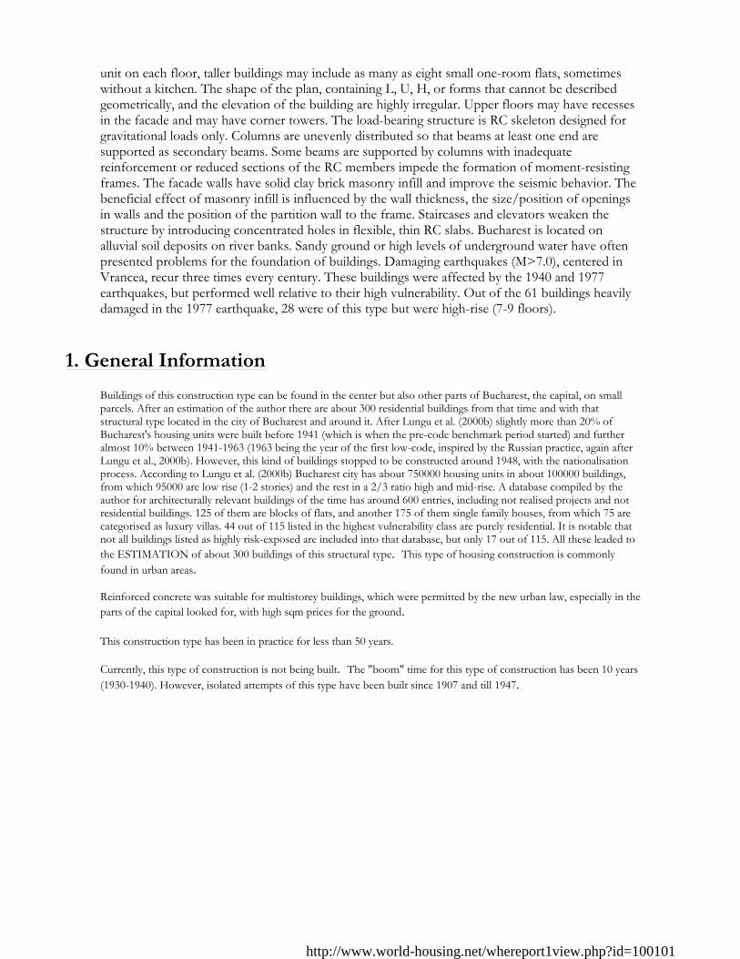
Figure 1: Perspective drawing of a model building
Figure 2: Axonometric view of the whole building
Figure 3: Perspective view of typical building (from
Bostenaru(2004) figure 3-2).
http://www.world-housing.net/whereport1view.php?id=100101
17). 2.4 Modification to Building Some buildings were added new metallic or RC schelet wings. New partition walls (fig. 11).
3. Structural Details
3.1 Structural System
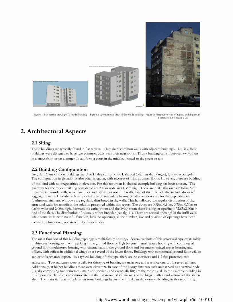
Figure 4: Layout of columns in a typical building
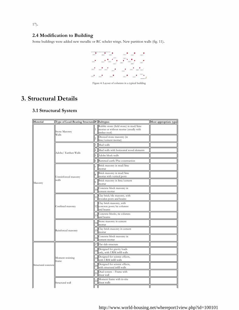
Material Type of Load-Bearing Structure # Subtypes Most appropriate type
Masonry
Stone Masonry Walls
1Rubble stone (field stone) in mud/lime mortar or without mortar (usually with timber roof)
�
2 Dressed stone masonry (in lime/cement mortar) �
Adobe/ Earthen Walls
3 Mud walls �4 Mud walls with horizontal wood elements �5 Adobe block walls �6 Rammed earth/Pise construction �
Unreinforced masonry walls
7 Brick masonry in mud/lime mortar �
8 Brick masonry in mud/lime mortar with vertical posts �
9 Brick masonry in lime/cement mortar �
10 Concrete block masonry in cement mortar �
Confined masonry
11 Clay brick/tile masonry, with wooden posts and beams �
12Clay brick masonry, with concrete posts/tie columns and beams
�
13 Concrete blocks, tie columns and beams �
Reinforced masonry
14 Stone masonry in cement mortar �
15 Clay brick masonry in cement mortar �
16 Concrete block masonry in cement mortar �
Structural concrete
Moment resisting frame
17 Flat slab structure �18 Designed for gravity loads
only, with URM infill walls �
19 Designed for seismic effects, with URM infill walls �
20 Designed for seismic effects, with structural infill walls �
21 Dual system – Frame with shear wall �
Structural wall22 Moment frame with in-situ
shear walls �
http://www.world-housing.net/whereport1view.php?id=100101
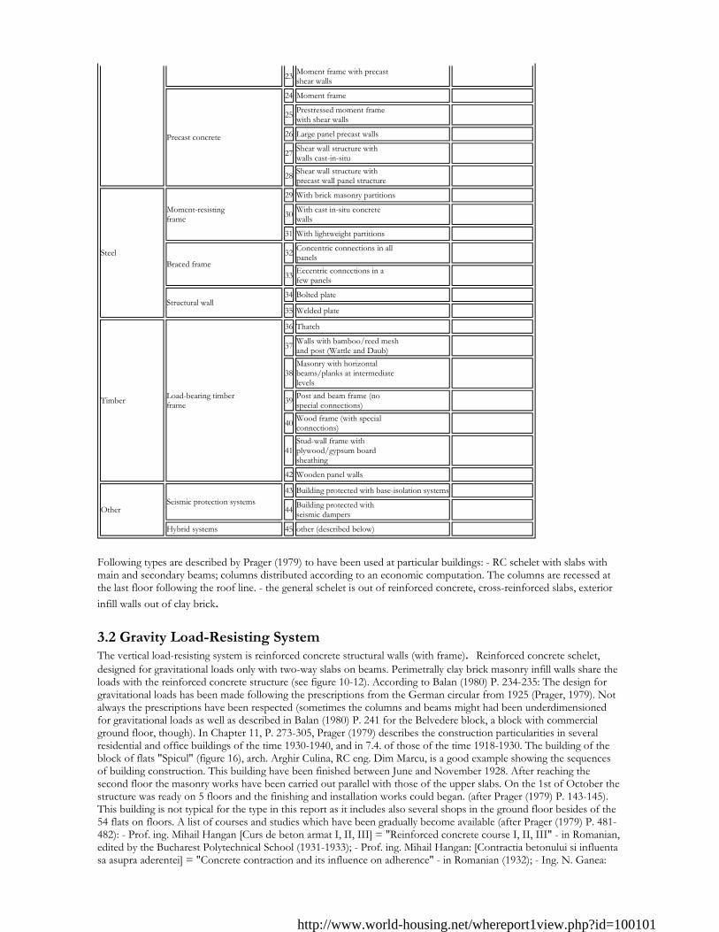
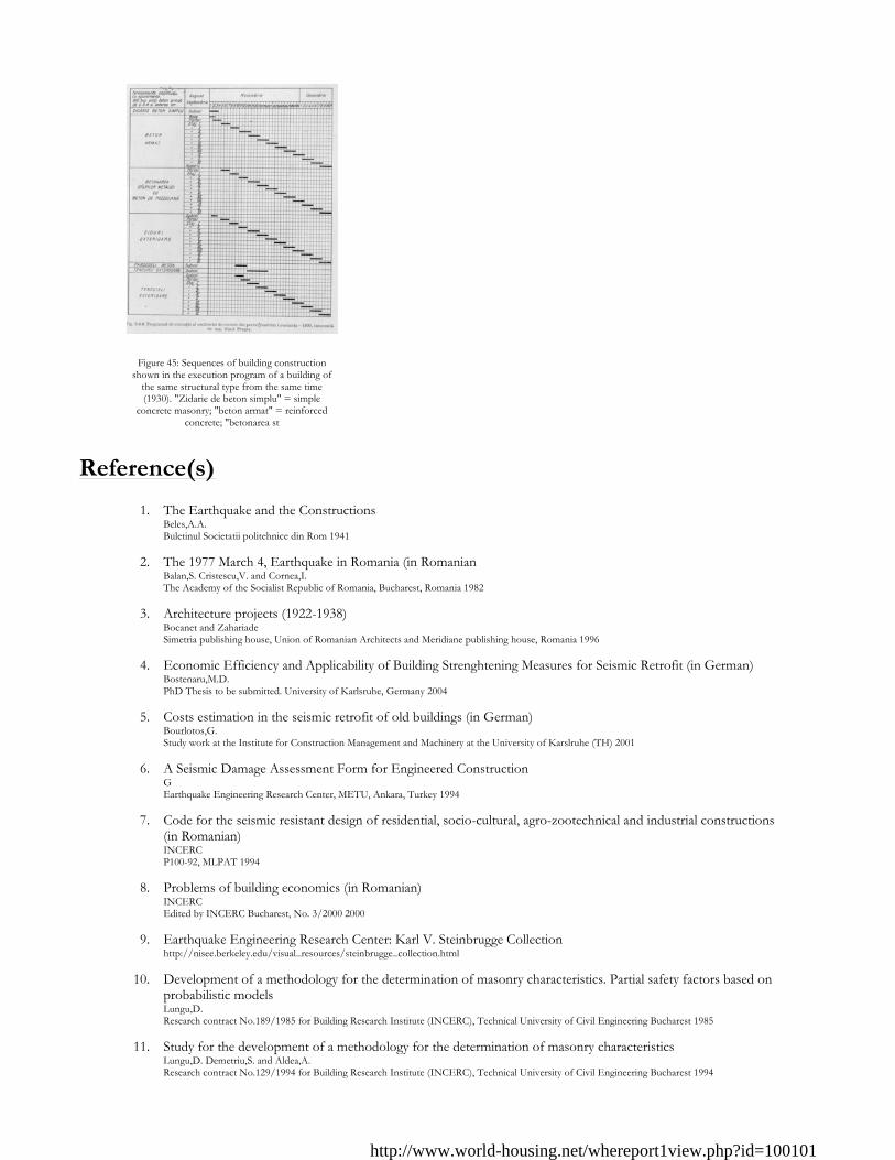
Following types are described by Prager (1979) to have been used at particular buildings: - RC schelet with slabs with main and secondary beams; columns distributed according to an economic computation. The columns are recessed at the last floor following the roof line. - the general schelet is out of reinforced concrete, cross-reinforced slabs, exterior infill walls out of clay brick. 3.2 Gravity Load-Resisting System The vertical load-resisting system is reinforced concrete structural walls (with frame). Reinforced concrete schelet, designed for gravitational loads only with two-way slabs on beams. Perimetrally clay brick masonry infill walls share the loads with the reinforced concrete structure (see figure 10-12). According to Balan (1980) P. 234-235: The design for gravitational loads has been made following the prescriptions from the German circular from 1925 (Prager, 1979). Not always the prescriptions have been respected (sometimes the columns and beams might had been underdimensioned for gravitational loads as well as described in Balan (1980) P. 241 for the Belvedere block, a block with commercial ground floor, though). In Chapter 11, P. 273-305, Prager (1979) describes the construction particularities in several residential and office buildings of the time 1930-1940, and in 7.4. of those of the time 1918-1930. The building of the block of flats "Spicul" (figure 16), arch. Arghir Culina, RC eng. Dim Marcu, is a good example showing the sequences of building construction. This building have been finished between June and November 1928. After reaching the second floor the masonry works have been carried out parallel with those of the upper slabs. On the 1st of October the structure was ready on 5 floors and the finishing and installation works could began. (after Prager (1979) P. 143-145). This building is not typical for the type in this report as it includes also several shops in the ground floor besides of the 54 flats on floors. A list of courses and studies which have been gradually become available (after Prager (1979) P. 481-482): - Prof. ing. Mihail Hangan [Curs de beton armat I, II, III] = "Reinforced concrete course I, II, III" - in Romanian, edited by the Bucharest Polytechnical School (1931-1933); - Prof. ing. Mihail Hangan: [Contractia betonului si influenta sa asupra aderentei] = "Concrete contraction and its influence on adherence" - in Romanian (1932); - Ing. N. Ganea:
23 Moment frame with precast shear walls �
Precast concrete
24 Moment frame �25 Prestressed moment frame
with shear walls �26 Large panel precast walls �27 Shear wall structure with
walls cast-in-situ �
28 Shear wall structure with precast wall panel structure �
Steel
Moment-resisting frame
29 With brick masonry partitions �30 With cast in-situ concrete
walls �31 With lightweight partitions �
Braced frame32 Concentric connections in all
panels �
33 Eccentric connections in a few panels �
Structural wall34 Bolted plate �35 Welded plate �
Timber Load-bearing timber frame
36 Thatch �37 Walls with bamboo/reed mesh
and post (Wattle and Daub) �
38Masonry with horizontal beams/planks at intermediate levels
�
39 Post and beam frame (no special connections) �
40 Wood frame (with special connections) �
41Stud-wall frame with plywood/gypsum board sheathing
�
42 Wooden panel walls �
OtherSeismic protection systems
43 Building protected with base-isolation systems �44 Building protected with
seismic dampers �Hybrid systems 45 other (described below) �
http://www.world-housing.net/whereport1view.php?id=100101
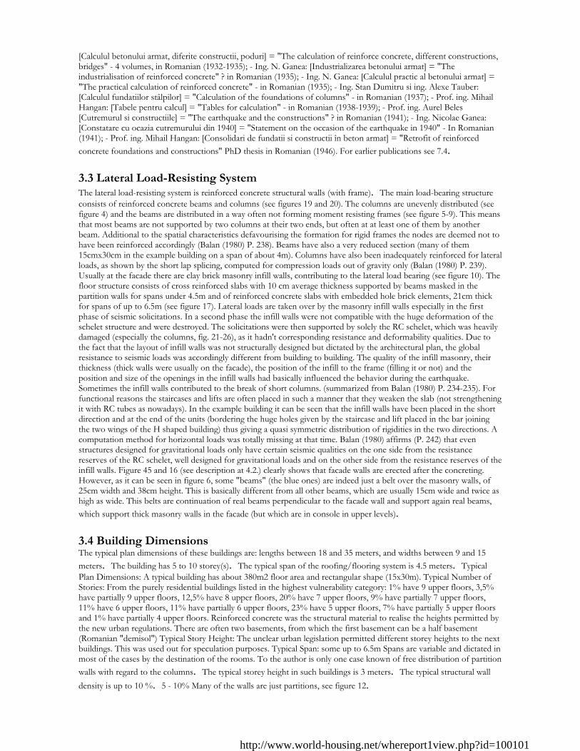
[Calculul betonului armat, diferite constructii, poduri] = "The calculation of reinforce concrete, different constructions, bridges" - 4 volumes, in Romanian (1932-1935); - Ing. N. Ganea: [Industrializarea betonului armat] = "The industrialisation of reinforced concrete" ? in Romanian (1935); - Ing. N. Ganea: [Calculul practic al betonului armat] = "The practical calculation of reinforced concrete" - in Romanian (1935); - Ing. Stan Dumitru si ing. Alexe Tauber: [Calculul fundatiilor stâlpilor] = "Calculation of the foundations of columns" - in Romanian (1937); - Prof. ing. Mihail Hangan: [Tabele pentru calcul] = "Tables for calculation" - in Romanian (1938-1939); - Prof. ing. Aurel Beles [Cutremurul si constructiile] = "The earthquake and the constructions" ? in Romanian (1941); - Ing. Nicolae Ganea: [Constatare cu ocazia cutremurului din 1940] = "Statement on the occasion of the earthquake in 1940" - In Romanian (1941); - Prof. ing. Mihail Hangan: [Consolidari de fundatii si constructii în beton armat] = "Retrofit of reinforced concrete foundations and constructions" PhD thesis in Romanian (1946). For earlier publications see 7.4. 3.3 Lateral Load-Resisting System The lateral load-resisting system is reinforced concrete structural walls (with frame). The main load-bearing structure consists of reinforced concrete beams and columns (see figures 19 and 20). The columns are unevenly distributed (see figure 4) and the beams are distributed in a way often not forming moment resisting frames (see figure 5-9). This means that most beams are not supported by two columns at their two ends, but often at at least one of them by another beam. Additional to the spatial characteristics defavourising the formation for rigid frames the nodes are deemed not to have been reinforced accordingly (Balan (1980) P. 238). Beams have also a very reduced section (many of them 15cmx30cm in the example building on a span of about 4m). Columns have also been inadequately reinforced for lateral loads, as shown by the short lap splicing, computed for compression loads out of gravity only (Balan (1980) P. 239). Usually at the facade there are clay brick masonry infill walls, contributing to the lateral load bearing (see figure 10). The floor structure consists of cross reinforced slabs with 10 cm average thickness supported by beams masked in the partition walls for spans under 4.5m and of reinforced concrete slabs with embedded hole brick elements, 21cm thick for spans of up to 6.5m (see figure 17). Lateral loads are taken over by the masonry infill walls especially in the first phase of seismic solicitations. In a second phase the infill walls were not compatible with the huge deformation of the schelet structure and were destroyed. The solicitations were then supported by solely the RC schelet, which was heavily damaged (especially the columns, fig. 21-26), as it hadn't corresponding resistance and deformability qualities. Due to the fact that the layout of infill walls was not structurally designed but dictated by the architectural plan, the global resistance to seismic loads was accordingly different from building to building. The quality of the infill masonry, their thickness (thick walls were usually on the facade), the position of the infill to the frame (filling it or not) and the position and size of the openings in the infill walls had basically influenced the behavior during the earthquake. Sometimes the infill walls contributed to the break of short columns. (summarized from Balan (1980) P. 234-235). For functional reasons the staircases and lifts are often placed in such a manner that they weaken the slab (not strengthening it with RC tubes as nowadays). In the example building it can be seen that the infill walls have been placed in the short direction and at the end of the units (bordering the huge holes given by the staircase and lift placed in the bar joining the two wings of the H shaped building) thus giving a quasi symmetric distribution of rigidities in the two directions. A computation method for horizontal loads was totally missing at that time. Balan (1980) affirms (P. 242) that even structures designed for gravitational loads only have certain seismic qualities on the one side from the resistance reserves of the RC schelet, well designed for gravitational loads and on the other side from the resistance reserves of the infill walls. Figure 45 and 16 (see description at 4.2.) clearly shows that facade walls are erected after the concreting. However, as it can be seen in figure 6, some "beams" (the blue ones) are indeed just a belt over the masonry walls, of 25cm width and 38cm height. This is basically different from all other beams, which are usually 15cm wide and twice as high as wide. This belts are continuation of real beams perpendicular to the facade wall and support again real beams, which support thick masonry walls in the facade (but which are in console in upper levels). 3.4 Building Dimensions The typical plan dimensions of these buildings are: lengths between 18 and 35 meters, and widths between 9 and 15 meters. The building has 5 to 10 storey(s). The typical span of the roofing/flooring system is 4.5 meters. Typical Plan Dimensions: A typical building has about 380m2 floor area and rectangular shape (15x30m). Typical Number of Stories: From the purely residential buildings listed in the highest vulnerability category: 1% have 9 upper floors, 3,5% have partially 9 upper floors, 12,5% have 8 upper floors, 20% have 7 upper floors, 9% have partially 7 upper floors, 11% have 6 upper floors, 11% have partially 6 upper floors, 23% have 5 upper floors, 7% have partially 5 upper floors and 1% have partially 4 upper floors. Reinforced concrete was the structural material to realise the heights permitted by the new urban regulations. There are often two basements, from which the first basement can be a half basement (Romanian "demisol") Typical Story Height: The unclear urban legislation permitted different storey heights to the next buildings. This was used out for speculation purposes. Typical Span: some up to 6.5m Spans are variable and dictated in most of the cases by the destination of the rooms. To the author is only one case known of free distribution of partition walls with regard to the columns. The typical storey height in such buildings is 3 meters. The typical structural wall density is up to 10 %. 5 - 10% Many of the walls are just partitions, see figure 12.
http://www.world-housing.net/whereport1view.php?id=100101
3.5 Floor and Roof System
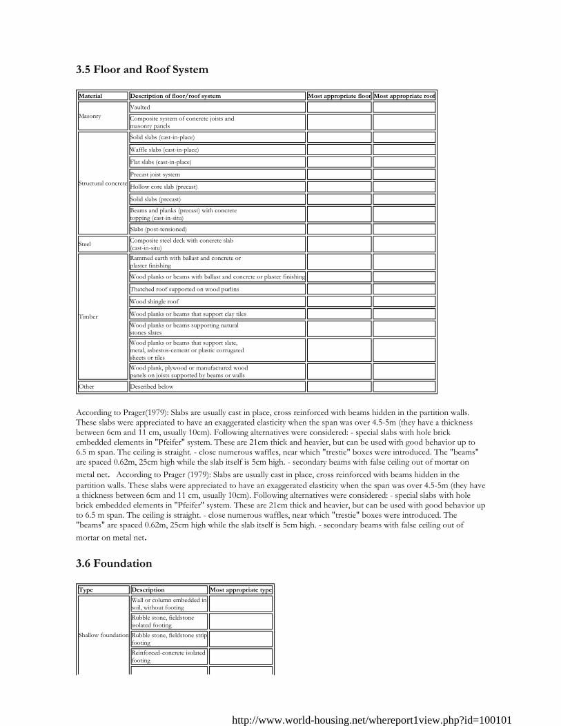
According to Prager(1979): Slabs are usually cast in place, cross reinforced with beams hidden in the partition walls. These slabs were appreciated to have an exaggerated elasticity when the span was over 4.5-5m (they have a thickness between 6cm and 11 cm, usually 10cm). Following alternatives were considered: - special slabs with hole brick embedded elements in "Pfeifer" system. These are 21cm thick and heavier, but can be used with good behavior up to 6.5 m span. The ceiling is straight. - close numerous waffles, near which "trestie" boxes were introduced. The "beams" are spaced 0.62m, 25cm high while the slab itself is 5cm high. - secondary beams with false ceiling out of mortar on metal net. According to Prager (1979): Slabs are usually cast in place, cross reinforced with beams hidden in the partition walls. These slabs were appreciated to have an exaggerated elasticity when the span was over 4.5-5m (they have a thickness between 6cm and 11 cm, usually 10cm). Following alternatives were considered: - special slabs with hole brick embedded elements in "Pfeifer" system. These are 21cm thick and heavier, but can be used with good behavior up to 6.5 m span. The ceiling is straight. - close numerous waffles, near which "trestie" boxes were introduced. The "beams" are spaced 0.62m, 25cm high while the slab itself is 5cm high. - secondary beams with false ceiling out of mortar on metal net. 3.6 Foundation
Material Description of floor/roof system Most appropriate floor Most appropriate roof
MasonryVaulted � �Composite system of concrete joists and masonry panels � �
Structural concrete
Solid slabs (cast-in-place) � �Waffle slabs (cast-in-place) � �Flat slabs (cast-in-place) � �Precast joist system � �Hollow core slab (precast) � �Solid slabs (precast) � �Beams and planks (precast) with concrete topping (cast-in-situ) � �Slabs (post-tensioned) � �
Steel Composite steel deck with concrete slab (cast-in-situ) � �
Timber
Rammed earth with ballast and concrete or plaster finishing � �Wood planks or beams with ballast and concrete or plaster finishing � �Thatched roof supported on wood purlins � �Wood shingle roof � �Wood planks or beams that support clay tiles � �Wood planks or beams supporting natural stones slates � �Wood planks or beams that support slate, metal, asbestos-cement or plastic corrugated sheets or tiles
� �
Wood plank, plywood or manufactured wood panels on joists supported by beams or walls � �
Other Described below � �
Type Description Most appropriate type
Shallow foundation
Wall or column embedded in soil, without footing �Rubble stone, fieldstone isolated footing �Rubble stone, fieldstone stripfooting �Reinforced-concrete isolated footing �
http://www.world-housing.net/whereport1view.php?id=100101
The types of foundation differ according to the ground on which the building has been made. Few buildings were made on good foundation ground, with isolated footing. Most foundations raised some problems. Following types are described to be used at particular buildings by Prager (1979): - RC strips on sand, sometimes connected with beams. Some are founded on the sand layer under the underground water layer. - deep foundations of 7-8m - general RC mat foundation designed for 1,2 kgf/sq cm for a block of flats with 7 floors on sandy ground with water mirror at 3,5m. On a similar weak terrain, with maximal allowed pressure 0.80kfg/cm2 and water saturated (near Cismigiu lake), mat foundation of 50cm was used. Mat foundation was used in several another cases when founding on sandy terrain at around -7.5m (two basements). Mat foundation was also used when underground water was high (-6m for buildings close to Dambovita river). - a special foundation used at an office building of the same structural type was used on a special ground saturated with water. It was a mat foundation with difficult works. To strengthen the ground steel tubes were embedded into the mat at about 1m distance. After finishing the structure of the building cement mortar was injected into these tubes at 3-4 at controlling the filling and spreading effect in the matt to the neighboring holes. The building above was 30m high, the admitted pressure on the ground 1.2-1.4 kgf/square cm. It behaved well at the 1940 earthquake. - on alluvial soil deposit: perimetral columns founded on simple concrete continuous wall of 50cm thickness on the whole height of two basements. Middle columns going down to reinforced concrete strips which support also the weight of the basement wall between them. - a special foundation work was due when the neighbouring buildings had a higher foundation. A case is described by Prager, when the foundation of the neighbouring building was 4m higher as the two basements for the new building. The new foundation was in a sand and gravel layer, made through 5 vertical deep holes, connected by a tunnel-gallery of 1,6x1,8m, in which then the new reinforced concrete strip was constructed, on which the masonry of the two basement was made, in successive parts, after which the ground was excavated at 6,3m depth till the street. The neighbouring building was founded on a compact resistent "argila" layer and was later extended vertically with 3 upper floors. Some other foundations opened realisation problems as well. Such one was on sandy terrain where the foundations were made through deep holes, followed by casting the slab over basement. The diggen sand proved to be so clear that it could be used for the concrete and masonry works.
Reinforced-concrete strip footing �Mat foundation �No foundation �
Deep foundation
Reinforced-concrete bearing piles �Reinforced-concrete skin friction piles �Steel bearing piles �Steel skin friction piles �Wood piles �Cast-in-place concrete piers �Caissons �
Other Described below �
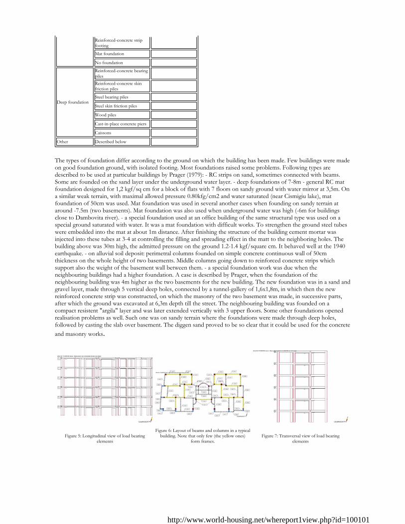
Figure 5: Longitudinal view of load bearing
elements
Figure 6: Layout of beams and columns in a typical
building. Note that only few (the yellow ones) form frames.
Figure 7: Transversal view of load bearing
elements
http://www.world-housing.net/whereport1view.php?id=100101
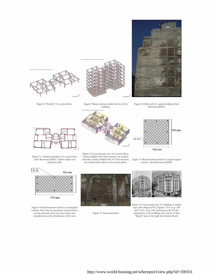
Figure 8: "Schelet" of a current floor.
Figure 9: Beam-column schelet for the whole
building.
Figure 10: Side wall of a typical building (from
Bostenaru(2004))
Figure 11: Architectural plan of a current floor
(after Bostenaru(2004)). Yellow marks new partition walls.
Figure 12: Axonometric view of a current floor. Frames infilled with 34cm masonry are marked
with blue, frames infileld with 10-15cm masonry are marked with yellow in the section plane.
Figure 13: Reinforcement detail of a typical square
column. (from Bostenaru(2004))
Figure 14: Reinforcement detail at a rectangular column. Note that the geometric characteristics,
not the physical ones, have been taken into consideration at the distribution of the bars.
Figure 15: Structural detail
Figure 16: Construction site of a building of similar
type (after Prager(1979), Figures 7.4.9. on p. 144 and 7.4.10. on p. 145, featuring on the left the
organisation of the building site at block of flats "Spicul" and on the rigth the finished block)
http://www.world-housing.net/whereport1view.php?id=100101
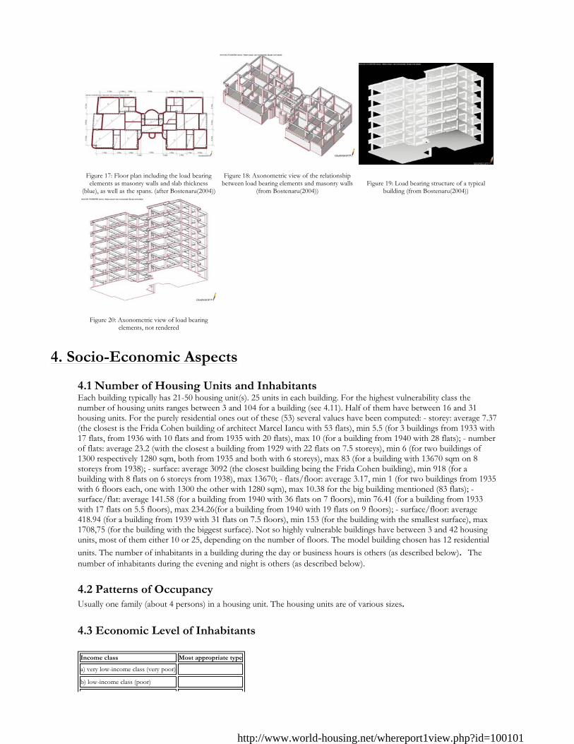
4. Socio-Economic Aspects
4.1 Number of Housing Units and Inhabitants Each building typically has 21-50 housing unit(s). 25 units in each building. For the highest vulnerability class the number of housing units ranges between 3 and 104 for a building (see 4.11). Half of them have between 16 and 31 housing units. For the purely residential ones out of these (53) several values have been computed: - storey: average 7.37 (the closest is the Frida Cohen building of architect Marcel Iancu with 53 flats), min 5.5 (for 3 buildings from 1933 with 17 flats, from 1936 with 10 flats and from 1935 with 20 flats), max 10 (for a building from 1940 with 28 flats); - number of flats: average 23.2 (with the closest a building from 1929 with 22 flats on 7.5 storeys), min 6 (for two buildings of 1300 respectively 1280 sqm, both from 1935 and both with 6 storeys), max 83 (for a building with 13670 sqm on 8 storeys from 1938); - surface: average 3092 (the closest building being the Frida Cohen building), min 918 (for a building with 8 flats on 6 storeys from 1938), max 13670; - flats/floor: average 3.17, min 1 (for two buildings from 1935 with 6 floors each, one with 1300 the other with 1280 sqm), max 10.38 for the big building mentioned (83 flats); - surface/flat: average 141.58 (for a building from 1940 with 36 flats on 7 floors), min 76.41 (for a building from 1933 with 17 flats on 5.5 floors), max 234.26(for a building from 1940 with 19 flats on 9 floors); - surface/floor: average 418.94 (for a building from 1939 with 31 flats on 7.5 floors), min 153 (for the building with the smallest surface), max 1708,75 (for the building with the biggest surface). Not so highly vulnerable buildings have between 3 and 42 housing units, most of them either 10 or 25, depending on the number of floors. The model building chosen has 12 residential units. The number of inhabitants in a building during the day or business hours is others (as described below). The number of inhabitants during the evening and night is others (as described below). 4.2 Patterns of Occupancy Usually one family (about 4 persons) in a housing unit. The housing units are of various sizes. 4.3 Economic Level of Inhabitants
Figure 17: Floor plan including the load bearing
elements as masonry walls and slab thickness (blue), as well as the spans. (after Bostenaru(2004))
Figure 18: Axonometric view of the relationship
between load bearing elements and masonry walls (from Bostenaru(2004))
Figure 19: Load bearing structure of a typical
building (from Bostenaru(2004))
Figure 20: Axonometric view of load bearing
elements, not rendered
Income class Most appropriate type
a) very low-income class (very poor) �b) low-income class (poor) �
http://www.world-housing.net/whereport1view.php?id=100101
These buildings have been designed as luxury residences. They were taken over in state property in the communism time and have been recently given back to their previous owners.
According to Prager (1979): The state and public administration built little, apart from reparation works after WWI and some blocks of flats from the social assurance fond. After 1929 and the monetary reform investments were made into blocks of flats especially from richer people from the province wishing to move to the capital. They were supported by bank credits. Especially in the sustained activity after 1929 the urban housing was built on credit base. More future owners contributed to the construction financing. In each housing unit, there are 1 bathroom(s) without toilet(s), 1 toilet(s) only and 1 bathroom(s) including toilet(s). 4.4 Ownership The type of ownership or occupancy is individual ownership.
This time a characteristic urban housing type develops: the block of flats with residences under the same roof, constituting the common property of a civil association, ruled by a special law of common use.
c) middle-income class �d) high-income class (rich) �
Ratio of housing unit price to annual income Most appropriate type
5:1 or worse �4:1 �3:1 �1:1 or better �
What is a typical source of financing for buildings of this type?
Most appropriate type
Owner financed �Personal savings �Informal network: friends and relatives �Small lending institutions / micro-finance institutions �Commercial banks/mortgages �Employers �Investment pools �Government-owned housing �Combination (explain below) �other (explain below) �
Type of ownership or occupancy?
Most appropriate type
Renting �outright ownership �Ownership with debt (mortgage or other) �Individual ownership �Ownership by a group or pool ofpersons �Long-term lease �other (explain below) �
http://www.world-housing.net/whereport1view.php?id=100101
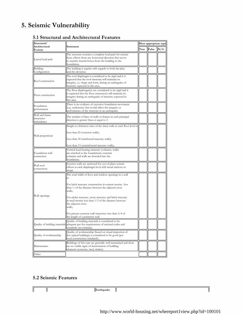
5. Seismic Vulnerability
5.1 Structural and Architectural Features
5.2 Seismic Features
Structural/ Architectural Feature
StatementMost appropriate type
True False N/A
Lateral load path
The structure contains a complete load path for seismic force effects from any horizontal direction that serves to transfer inertial forces from the building to the foundation.
� � �
Building Configuration
The building is regular with regards to both the plan and the elevation. � � �
Roof construction
The roof diaphragm is considered to be rigid and it is expected that the roof structure will maintain its integrity, i.e. shape and form, during an earthquake of intensity expected in this area.
� � �
Floor construction
The floor diaphragm(s) are considered to be rigid and it is expected that the floor structure(s) will maintain its integrity during an earthquake of intensity expected in this area.
� � �
Foundation performance
There is no evidence of excessive foundation movement (e.g. settlement) that would affect the integrity or performance of the structure in an earthquake.
� � �
Wall and frame structures- redundancy
The number of lines of walls or frames in each principal direction is greater than or equal to 2. � � �
Wall proportions
Height-to-thickness ratio of the shear walls at each floor level is: Less than 25 (concrete walls); Less than 30 (reinforced masonry walls); Less than 13 (unreinforced masonry walls);
� � �
Foundation-wall connection
Vertical load-bearing elements (columns, walls) are attached to the foundations; concrete columns and walls are doweled into the foundation.
� � �
Wall-roof connections
Exterior walls are anchored for out-of-plane seismic effects at each diaphragm level with metal anchors or straps
� � �
Wall openings
The total width of door and window openings in a wall is: For brick masonry construction in cement mortar : less than ½ of the distance between the adjacent cross walls; For adobe masonry, stone masonry and brick masonry in mud mortar: less than 1/3 of the distance between the adjacent cross walls; For precast concrete wall structures: less than 3/4 of the length of a perimeter wall.
� � �
Quality of building materialsQuality of building materials is considered to be adequate per the requirements of national codes and standards (an estimate).
� � �
Quality of workmanshipQuality of workmanship (based on visual inspection of few typical buildings) is considered to be good (per local construction standards).
� � �
Maintenance Buildings of this type are generally well maintained and there are no visible signs of deterioration of building elements (concrete, steel, timber)
� � �
Other � � �
Earthquake
http://www.world-housing.net/whereport1view.php?id=100101
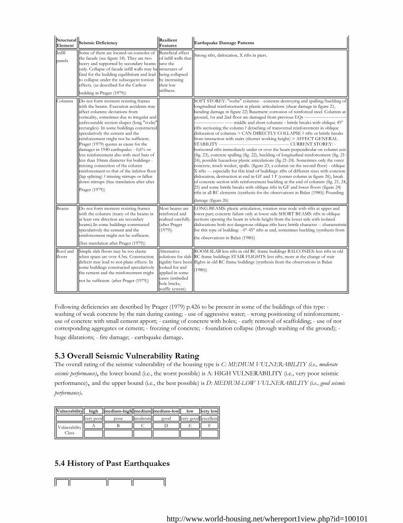
Following deficiencies are described by Prager (1979) p.426 to be present in some of the buildings of this type: - washing of weak concrete by the rain during casting; - use of aggressive water; - wrong positioning of reinforcement; - use of concrete with small cement apport; - casting of concrete with holes; - early removal of scaffolding; - use of not corresponding aggregates or cement; - freezing of concrete; - foundation collapse (through washing of the ground); - huge dilatations; - fire damage; - earthquake damage. 5.3 Overall Seismic Vulnerability Rating The overall rating of the seismic vulnerability of the housing type is C: MEDIUM VULNERABILITY (i.e., moderate seismic performance), the lower bound (i.e., the worst possible) is A: HIGH VULNERABILITY (i.e., very poor seismic performance), and the upper bound (i.e., the best possible) is D: MEDIUM-LOW VULNERABILITY (i.e., good seismic performance).
5.4 History of Past Earthquakes
Structural Element
Seismic DeficiencyResilient Features
Earthquake Damage Patterns
Infill
panels Some of them are located on consoles of the facade (see figure 18). They are two heavy and supported by secondary beams only. Collapse of facade infill walls may befatal for the building equilibrium and lead to collapse under the subsequent torsion effects. (as described for the Carlton
building in Prager (1979))
Beneficial effect of infill walls that save the structures of being collapsed by increasing their low stiffness.
Strong rifts, dislocation, X rifts in piers.
Columns Do not form moment resisting frames with the beams. Execution accidents may affect columns: deviations from verticality, sometimes due to irregular and unfavourable section shapes (long "svelte" rectangles). In some buildings constructed speculatively the cement and the reinforcement might not be sufficient. Prager (1979) quotes as cause for the damages in 1940 earthquake: - 0,6% or less reinforcement also with steel bars of less than 10mm diameter for buildings - missing connection of the column reinforcement to that of the inferior floor (lap splicing) ? missing stirrups or fallen down stirrups (free translation after after
Prager (1979))
SOFT STOREY: "svelte" columns: - concrete destroying and spalling/buckling of longitudinal reinforcement at plastic articulations (shear damage in figure 21, bending damage in figure 22) Basement: corrosion of reinforced steel. Columns at ground, 1st and 2nd floor are damaged from previous EQs ------------------------------------------------ ----- middle and short columns: - brittle breaks with oblique 45° rifts sectioning the column ? detaching of transversal reinforcement in oblique dislocation of columns > CAN DIRECTLY COLLAPSE ? rifts or brittle breaks from interaction with stairs (shorter working height) > AFFECT GENERAL STABILITY ----------------------------------------------- CURRENT STOREY: - horizontal rifts immediately under or over the beam perpendicular on column axis (fig. 23), concrete spalling (fig. 22), buckling of longitudinal reinforcement (fig. 21-24), possible hazardous plastic articulations (fig 21-24). Sometimes only the outer concrete, much weaker, spalls. (figure 23, a column on the second floor) - oblique X rifts --- especially for this kind of buildings: rifts of different sizes with concrete dislocation, destruction at end in GF and 1 F (corner column in figure 26), break of concrete section with reinforcement buckling at the end of columns (fig. 21, 24, 25) and some brittle breaks with oblique rifts in GF and lower floors (figure 24) rifts in all RC elements (synthesis for the observations in Balan (1980)) Pounding
damage (figure 26) Beams Do not form moment resisting frames
with the columns (many of the beams in at least one direction are secondary beams).In some buildings constructed speculatively the cement and the reinforcement might not be sufficient.
(free translation after Prager (1979))
Most beams are reinforced and realised carefully. (after Prager (1979))
LONG BEAMS: plastic articulation, rotation near node with rifts at upper and lower part; concrete failure only at lower side SHORT BEAMS: rifts in oblique sections opening the beam in whole height from the lower side with isolated dislocations both not dangerous oblique rifts have brittle character -- characteristic for this type of building: - 0°-45° rifts at end, sometimes buckling (synthesis from
the observations in Balan (1980))
Roof and floors
Simple slab floors may be too elastic when spans are over 4.5m. Construction defects may lead to not-plane effects. In some buildings constructed speculatively the cement and the reinforcement might
not be sufficient. (after Prager (1979))
Alternative solutions for slab rigidity have been looked for and applied in some cases (embeded hole bricks, waffle system).
ROOM SLAB less rifts in old RC frame buildings BALCONIES: less rifts in old RC frame buildings STAIR FLIGHTS: less rifts, more at the change of stair flights in old RC frame buildings (synthesis from the observations in Balan
(1980))
Vulnerability high medium-high medium medium-low low very low
very poor poor moderate good very good excellent
Vulnerability Class
A B C D E F
� � � � � �
http://www.world-housing.net/whereport1view.php?id=100101
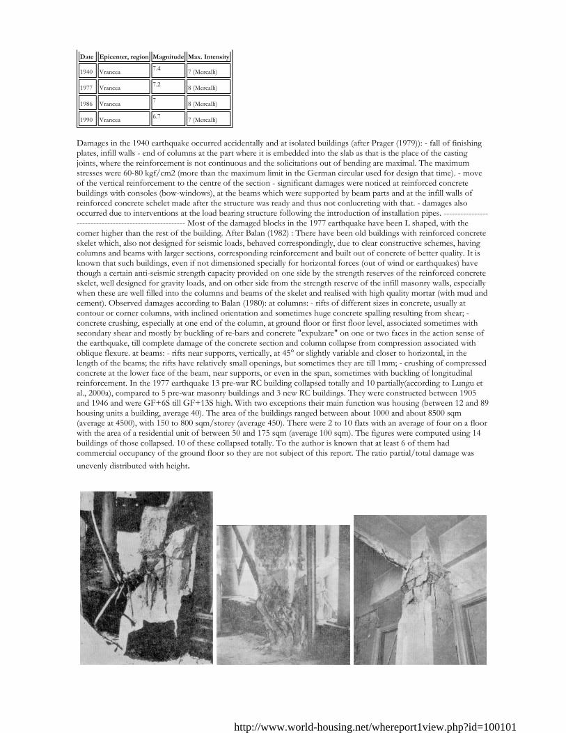
Damages in the 1940 earthquake occurred accidentally and at isolated buildings (after Prager (1979)): - fall of finishing plates, infill walls - end of columns at the part where it is embedded into the slab as that is the place of the casting joints, where the reinforcement is not continuous and the solicitations out of bending are maximal. The maximum stresses were 60-80 kgf/cm2 (more than the maximum limit in the German circular used for design that time). - move of the vertical reinforcement to the centre of the section - significant damages were noticed at reinforced concrete buildings with consoles (bow-windows), at the beams which were supported by beam parts and at the infill walls of reinforced concrete schelet made after the structure was ready and thus not conlucreting with that. - damages also occurred due to interventions at the load bearing structure following the introduction of installation pipes. ------------------------------------------------------- Most of the damaged blocks in the 1977 earthquake have been L shaped, with the corner higher than the rest of the building. After Balan (1982) : There have been old buildings with reinforced concrete skelet which, also not designed for seismic loads, behaved correspondingly, due to clear constructive schemes, having columns and beams with larger sections, corresponding reinforcement and built out of concrete of better quality. It is known that such buildings, even if not dimensioned specially for horizontal forces (out of wind or earthquakes) have though a certain anti-seismic strength capacity provided on one side by the strength reserves of the reinforced concrete skelet, well designed for gravity loads, and on other side from the strength reserve of the infill masonry walls, especially when these are well filled into the columns and beams of the skelet and realised with high quality mortar (with mud and cement). Observed damages according to Balan (1980): at columns: - rifts of different sizes in concrete, usually at contour or corner columns, with inclined orientation and sometimes huge concrete spalling resulting from shear; - concrete crushing, especially at one end of the column, at ground floor or first floor level, associated sometimes with secondary shear and mostly by buckling of re-bars and concrete "expulzare" on one or two faces in the action sense of the earthquake, till complete damage of the concrete section and column collapse from compression associated with oblique flexure. at beams: - rifts near supports, vertically, at 45° or slightly variable and closer to horizontal, in the length of the beams; the rifts have relatively small openings, but sometimes they are till 1mm; - crushing of compressed concrete at the lower face of the beam, near supports, or even in the span, sometimes with buckling of longitudinal reinforcement. In the 1977 earthquake 13 pre-war RC building collapsed totally and 10 partially(according to Lungu et al., 2000a), compared to 5 pre-war masonry buildings and 3 new RC buildings. They were constructed between 1905 and 1946 and were GF+6S till GF+13S high. With two exceptions their main function was housing (between 12 and 89 housing units a building, average 40). The area of the buildings ranged between about 1000 and about 8500 sqm (average at 4500), with 150 to 800 sqm/storey (average 450). There were 2 to 10 flats with an average of four on a floor with the area of a residential unit of between 50 and 175 sqm (average 100 sqm). The figures were computed using 14 buildings of those collapsed. 10 of these collapsed totally. To the author is known that at least 6 of them had commercial occupancy of the ground floor so they are not subject of this report. The ratio partial/total damage was unevenly distributed with height.
Date Epicenter, region Magnitude Max. Intensity
1940 Vrancea 7.4 7 (Mercalli) 1977 Vrancea 7.2 8 (Mercalli) 1986 Vrancea 7 8 (Mercalli) 1990 Vrancea 6.7 7 (Mercalli)
http://www.world-housing.net/whereport1view.php?id=100101
6. Construction
6.1 Building Materials
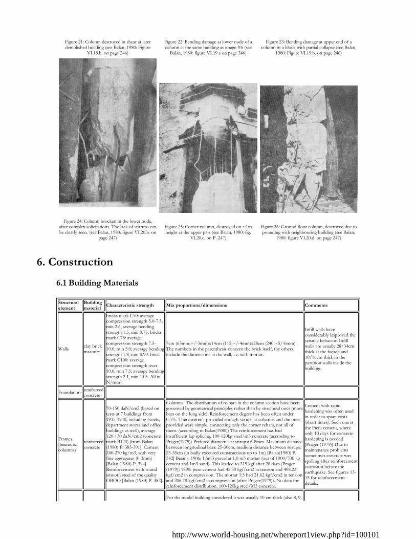
Figure 21: Column destroyed in shear at later demolished building (see Balan, 1980: Figure
VI.18.b. on page 246)
Figure 22: Bending damage at lower node of a column at the same building as image #6 (see
Balan, 1980: figure VI.19.a on page 246)
Figure 23: Bending damage at upper end of a column in a block with partial collapse (see Balan,
1980: Figure VI.19:b. on page 246)
Figure 24: Column brocken in the lower node,
after complex solicitations. The lack of stirrups can be clearly seen. (see Balan, 1980: figure VI.20.b. on
page 247)
Figure 25: Corner column, destroyed on ~1m height at the upper part (see Balan, 1980: fig.
VI.20.c. on P. 247)
Figure 26: Ground floor column, destroyed due to pounding with neighbouring building (see Balan,
1980: figure VI.20.d. on page 247)
Structural element
Building material
Characteristic strength Mix proportions/dimensions Comments
Walls clay brick masonry
bricks mark C50: average compression strength 5.0-7.5, min 2.6; average bending strength 1.5, min 0.75. bricks mark C75: average compression strength 7.5-10.0, min 5.0; average bending strength 1.8, min 0.90. brick mark C100: average compression strength over 10.0, min 7.5; average bending strength 2.1, min 1.05. All in N/mm².
7cm (63mm;+/-3mm)x14cm (115;+/-4mm)x28cm (240;+5/-6mm) The numbers in the parenthesis concern the brick itself, the others include the dimensions in the wall, i.e. with mortar.
Infill walls have considerably improved the seismic behavior. Infill walls are usually 28/34cm thick at the façade and 10/16cm thick in the partition walls inside the building.
Foundation reinforced concrete
Frames (beams & columns)
reinforced concrete
70-150 daN/cm2 (based on tests at 7 buildings from 1935-1940, including hotels, department stores and office buildings as well), average 120-130 daN/cm2 (concrete mark B120) [from Balan(1980) P. 385-391]. Cement 240-270 kg/m3, with very fine aggregates (0-3mm) [Balan (1980) P. 394] Reinforcement with round smooth steel of the quality OBOO [Balan (1980) P. 382].
Columns: The distribution of re-bars in the column section have been governed by geometrical principles rather than by structural ones (more bars on the long side). Reinforcement degree has been often under 0,5%. There weren't provided enough stirups at columns and the ones provided were simple, connecting only the corner rebars, not all of them. (according to Balan(1980)) The reinforcement has had insufficient lap splicing. 100-120kg steel/m3 concrete (accroding to Prager(1979)) Prefered diametres at stirups: 6-8mm. Maximum distance between longitudinal bars: 25-30cm, medium distance between stirups: 25-35cm (in badly executed constructions up to 1m) [Balan(1980) P. 382] Beams: 1906: 1,5m3 gravel at 1,0 m3 mortar (out of 1000/700 kg cement and 1m3 sand). This leaded to 215 kgf after 28 days (Prager(1979)) 1890: pure cement had 45.30 kgf/cm2 in tension and 408.23 kgf/cm2 in compression. The mortar 1:3 had 21.62 kgf/cm2 in tension and 206.78 kgf/cm2 in compression (after Prager(1979)). No data for reinforcement distribution. 100-120kg steel/M3 concrete.
Cement with rapid hardening was often used in order to spare costs (short times). Such one is the Fieni cement, where only 10 days for concrete hardening is needed. [Prager (1979)] Due to maintenance problems sometimes concrete was spalling after reinforcement corrosion before the earthquake. See figures 13-15 for reinforcement details.
For the model building considered it was usually 10 cm thick (also 8, 9,
http://www.world-housing.net/whereport1view.php?id=100101
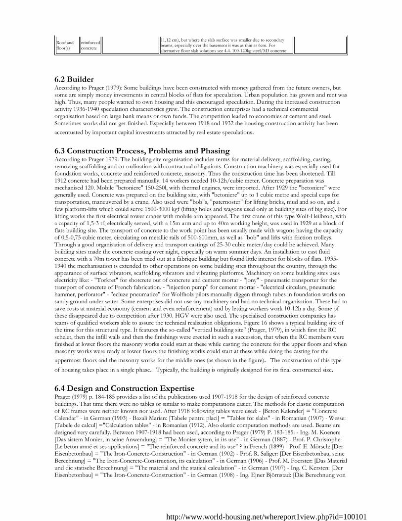
6.2 Builder According to Prager (1979): Some buildings have been constructed with money gathered from the future owners, but some are simply money investments in central blocks of flats for speculation. Urban population has grown and rent was high. Thus, many people wanted to own housing and this encouraged speculation. During the increased construction activity 1936-1940 speculation characteristics grew. The construction enterprises had a technical commercial organisation based on large bank means or own funds. The competition leaded to economies at cement and steel. Sometimes works did not get finished. Especially between 1918 and 1932 the housing construction activity has been accentuated by important capital investments attracted by real estate speculations. 6.3 Construction Process, Problems and Phasing According to Prager 1979: The building site organisation includes terms for material delivery, scaffolding, casting, removing scaffolding and co-ordination with contractual obligations. Construction machinery was especially used for foundation works, concrete and reinforced concrete, masonry. Thus the construction time has been shortened. Till 1912 concrete had been prepared manually. 14 workers needed 10-12h/cubic meter. Concrete preparation was mechanised 120. Mobile "betoniere" 150-250l, with thermal engines, were imported. After 1929 the "betoniere" were generally used. Concrete was prepared on the building site, with "betoniere" up to 1 cubic metre and special cups for transportation, maneuvered by a crane. Also used were "bob"s, "paternoster" for lifting bricks, mud and so on, and a few platform-lifts which could serve 1500-3000 kgf (lifting holes and wagons used only at building sites of big size). For lifting works the first electrical tower cranes with mobile arm appeared. The first crane of this type Wolf-Heilbron, with a capacity of 1,5-3 tf, electrically served, with a 15m arm and up to 40m working height, was used in 1929 at a block of flats building site. The transport of concrete to the work point has been usually made with wagons having the capacity of 0,5-0,75 cubic meter, circulating on metallic rails of 500-600mm, as well as "bob" and lifts with friction trolleys. Through a good organisation of delivery and transport castings of 25-30 cubic meter/day could be achieved. Many building sites made the concrete casting over night, especially on warm summer days. An installation to cast fluid concrete with a 70m tower has been tried out at a fabrique building but found little interest for blocks of flats. 1935-1940 the mechanisation is extended to other operations on some building sites throughout the country, through the appearance of surface vibrators, scaffolding vibrators and vibrating platforms. Machinery on some building sites uses electricity like: - "Torkret" for shotcrete out of concrete and cement mortar - "jony" - pneumatic transporter for the transport of concrete of French fabrication. - "injection pump" for cement mortar - "electrical circulars, pneumatic hammer, perforator" - "ecluze pneumatice" for Wolfholz pilots manually diggen through tubes in foundation works on sandy ground under water. Some enterprises did not use any machinery and had no technical organisation. These had to save costs at material economy (cement and even reinforcement) and by letting workers work 10-12h a day. Some of these disappeared due to competition after 1930. HGV were also used. The specialised construction companies has teams of qualified workers able to assure the technical realisation obligations. Figure 16 shows a typical building site of the time for this structural type. It features the so-called "vertical building site" (Prager, 1979), in which first the RC schelet, then the infill walls and then the finishings were erected in such a succession, that when the RC members were finished at lower floors the masonry works could start at these while casting the concrete for the upper floors and when masonry works were ready at lower floors the finishing works could start at these while doing the casting for the uppermost floors and the masonry works for the middle ones (as shown in the figure). The construction of this type of housing takes place in a single phase. Typically, the building is originally designed for its final constructed size. 6.4 Design and Construction Expertise Prager (1979) p. 184-185 provides a list of the publications used 1907-1918 for the design of reinforced concrete buildings. That time there were no tables or similar to make computations easier. The methods for elastic computation of RC frames were neither known nor used. After 1918 following tables were used: - [Beton Kalender] = "Concrete Calendar" - in German (1903) - Bazali Marian: [Tabele pentru placi] = "Tables for slabs" - in Romanian (1907) - Wesse: [Tabele de calcul] ="Calculation tables" - in Romanian (1912). Also elastic computation methods are used. Beams are designed very carefully. Between 1907-1918 had been used, according to Prager (1979) P. 183-185: - Ing. M. Koenen: [Das sistem Monier, in seine Anwendung] = "The Monier sytem, in its use" - in German (1887) - Prof. P. Christophe: [Le beton armé et ses applications] = "The reinforced concrete and its use" ? in French (1899) - Prof. E. Mörsch: [Der Eisenbetonbau] = "The Iron-Concrete-Construction" - in German (1902) - Prof. R. Saliger: [Der Eisenbetonbau, seine Berechnung] = "The Iron-Concrete-Construction, its calculation" - in German (1906) - Prof. M. Foerster: [Das Material und die statische Berechnung] = "The material and the statical calculation" - in German (1907) - Ing. C. Kersten: [Der Eisenbetonbau] = "The Iron-Concrete-Construction" - in German (1908) - Ing. Ejner Björnstad: [Die Berechnung von
Roof and floor(s)
reinforced concrete
11,12 cm), but where the slab surface was smaller due to secondary beams, especially over the basement it was as thin as 6cm. For alternative floor slab solutions see 4.4. 100-120kg steel/M3 concrete
http://www.world-housing.net/whereport1view.php?id=100101
Steifrahmen] = "The calculation of rigid frames" - in German (1909). Between 1920-1926 design offices specialised in reinforced concrete appeared. Construction works were carried out by particular "antreprize" like: "ing. Constantin M. Vasilescu", "Societatea de Beton si Fier" (founded 1906), "Antrepriza ing. Tiberiu Eremia", "Societatea Edilitatea", "Societatea Unirea", "Societatea Constructia Moderna" etc. They were organised for such works. Some owned modern specialised machinery, personal for technical leading, for steel, iron, scaffolding, wood works, repairing. They employed well formed masters for different working branches, on salary or hour base. There was a licitation system at state works based on guarantees, sometimes with invitation to licitation by "antreprize" verified for the technical capacity, the machinery inventory and the financial means. 1865 the "Legea Contabilitatii Publice" stated the rules for getting contracts, making payments and receiving ("receptie") the work. The general conditions were updated 1894. On the building sites there were technical control methods for the quality of aggregates, water, cement. Strength trials are made for compression on concrete cubes. Trials for break of reinforced concrete beams are also made. 1932 building site laboratories appeared, which monitored the quality of concrete and aggregates but only at public works. Further data about the progress in reinforced concrete design of the time are described by Prager (1979), p. 481-483. For a list of publications see 4.2. To the authors knowledge as frames are defined as a beam supported directly by two columns, which was very rarely the case in such constructions due to beams outside the axis and/or reduced section of the elements (see figure &, also pointed out in Balan (1980) P. 234). Balan (1980) additionally points out that the node reinforcement was designed for gravitational loads only, theoretically following the German circular from 1925 (P. 234 Balan (1980), P. 274 Prager(1979)), later method Cross. Also to the authors knowledge and supported by other research (ex. Penelis & Kappos (1997)) infill walls haven't been considered in computations until recently. Infill walls arranged as one single brace are mention ed in the contemporary code (P100-92). More even, it is known that the constructions of the time were designed as much more flexible as they proved as the masonry infill was not taken into consideration (see Balan (1980) P. 235). A huge number of this kind of buildings have been designed by renowned architects. They are characteristic for Bucharest's today's face, and most of them are to be found along the main N-S boulevard in the city. Emil Prager writes extensively in his book about the history of reinforced concrete in Romania about the co-operation between engineers and architects in that time (see reference). This was somehow stopped during the economic crisis, but came back to life after its end. It was this co-operation which made many reinforced concrete building initiatives possible. Both engineers and architects could be employed by building site organisation companies. Usually one or two architects (and their employees) made the architecture project. The reinforced concrete projects were made by an engineer. The supervision of construction work may be made again by the same or another engineer, or by an architect. Construction works were carried out by particular "antreprize", leaded by engineers or architects employed by the benefitors of the design works (state or, especially, private). The presence of the engineer and of the building site leader was obligatory at the casting of RC members, which started after the control of the scaffolding and supports and at the "reception" through "proces verbal" of the metal reinforcement mounted according to the project. In the honorary prices for the Architects Corps was included in 1934 that for a technical control on the building site the payment will be 30-50% higher. This occurred after noticing several defects in execution, like deformation of scaffolding for the slabs at upper floors after height differences of supports, not vertical columns, beams with obliques walls, especially when the technical control of the "diriginte de santier" was missing. Later the building permits required for reinforced concrete works to be signed by a diploma engineer, accredited by the avisation service. Civil engineers were there to assure the quality of work. They had to assure through their computations the strength and stability of the structure for the most difficult life conditions and use of the chosen site and to expose the safety coefficients prescribed to realise these conditions. Also the civil engineer had to prepare the technical data and necessary indications to prepare the aggregates necessary for the concrete, the quality of cement, the working conditions, the duration of execution and removing of formwork, and to follow the quality of execution on building sited in the corresponding time. 6.5 Building Codes and Standards This construction type is addressed by the codes/standards of the country. Title of the code or standard: - control methods - Year the first code/standard addressing this type of construction issued: 1932 prescriptions, 1941 precode National building code, material codes and seismic codes/standards: 1932 - prescriptions which spread fast: - granulometric study of the aggregates: a/c relation; - probes on cubes at 28 days (160kgf/cm2); - vibrating concrete till 2500kg/m3 characteristic weight is achieved. These were applied only at public works (they were included there in the functional specifications). [after Prager(1979)] When was the most recent code/standard addressing this construction type issued? This type of buildings nearly stopped to be constructed in the "pre-code" period (Lungu et al(2000b) after the HAZUS methodology), after the 1940 earthquake. The codes issued after that earthquake were P.I. - 1941 and I.-1945. Within that a seismic design coefficietnt of 5% has been adopted for shear walls and frames. Not that today practice prescribes 10% for flexible frame buildings and 12.5% for rigid shear wall buildings. see also 7.10. As described by Prager (1979) in the boom time (1933-1942) the dimensioning was made following the German prescriptions from 1916 and 1932 as well as [Prima lectie de beton armat] = "The first reinforced concrete lesson" in Romanian (1903) transformed in 1914 into [Curs de beton armat] = "Reinforced concrete course" in Romanian and 1930 into [Conferinta de beton armat] = "Reinforced concrete conference" (in Romanian). Until the 1940 earthquake
http://www.world-housing.net/whereport1view.php?id=100101
the design was made based on the German circular, which stipulated computation for gravitational and wind loads. After the 1940 earthquake, which leaded to heavy deteriorations at numerous buildings throughout the country, the Ministry of Public Works made a commission with the duty to elaborate the obligatory prescriptions for the computation and design of reinforced concrete works. The first provisional guidelines, preceding codes appeared 1942. The prescriptions published 1942 contained directives and dispositions very valuable for the design and realisation of constructions with reinforced concrete structure, obligatory for the design engineers which had to sign the permit projects. Especially the fall of the "Carlton" building, a block of flats of this type but with cinema at the lower floors, based on the "Consiliul Tehnic Superior din Ministerul Lucrarilor Publice" (The Superior Technical Council of the Public Works Ministery) the "Instructiuni pentru prevenirea deteriorarii constructiilor din cauza cutremurelor" (Instructions for preventing the deterioration of constructions due to earthquakes) was published in "Monitorul Oficial" no. 120 from May 1945. After that this type of buildings has been continued in a slightly different manner, as described in report #71. 6.6 Building Permits and Development Control Rules This type of construction is an engineered, and authorized as per development control rules. 1936 the master plan of Bucharest, one of the most innovative from that time appeared and this has prescribed the building rules. 1,2m recesses above a certain height have been prescribed in that regulations, for example, in order to lower street shadowing by high buildings. The height itself has been also prescribed, and there were prescriptions permitting a relatively high ground floor occupancy. The commercial ground floors have been supported by the regulation. Prager (1979) P. 90-96: After 1908 the main problem was the division of legal responsibility for the success of the works for which the owner has employed the architect as general designer and which had the responsibility of choice of the specific designer and of the supervision of works. This initial phase was influenced by the honorary quote for the reinforced concrete works design, which had to be stated by the architect. At that stage collegial agreements were made. After 1918 the signature of an engineer on the authorisation (permit) plans was required by the municipal services. Building permits are required to build this housing type. 6.7 Building Maintenance Typically, the building of this housing type is maintained by Owner(s). 6.8 Construction Economics This type of multiple housing units are not build any more. After Prager (1979): The reinforced concrete schelet did cost 12-15% of the complete construction cost. This is why prefabrication of metal parts after western model has not been practiced so much. The cast in place system was also chosen due to the low cost of the timber for scaffolding works and the lower cost of working force due to the mechanisation of casting works. No data are available about the absolute cost of such a building. However, Prager (1979) gives some figures about the costs variation: Average costs indices: - a block of flats at 1000 cubic meter built volume, with RC schelet: 1933 (100%), 1934 (102%), 1935 (104%), 1936 (110%), 1937 (120%), 1938 (127%), 1939 (137%), 1940 (187%), 1941 (298%), 1942 sem. I (426%) - a single family house type "The Society for Cheap Dwellings" Bucharest: 1933 (100%), 1934 (100%), 1935 (106%), 1936 (108%), 1937 (115%), 1938 (119%), 1939 (128%), 1940 (174%), 1941 (269%), 1942 sem. I (370%) Between 1926-1927 material prices increased, transportation means were lacking and inflation leaded to variation in the price of working force. After Prager (1979): A well organised construction enterprise had clear advantages. The high cost of the machinery described at 7.3 as well as the missing continuity of work on building site and the maintenance and use expenses determined that the "small mechanisation" developed only in special works, where their necessity was obvious. Some buildings have been constructed with great spread. An example: at a block of flats with 6 floors: 2 weeks for a floor of 600 sqm, the whole building being finished between June and November 1925. Availability of technology after Prager (1979) p. 456: For scaffolding antique means of wooden works were used. Bending and binding with wire of reinforcement bars was fast learned by the workers. It also did not need extensive work, since there were less than 100-120 kg steel/m3 concrete. Preparing of concrete out of local aggregates was fast learned by the constructors, as it was similar to the preparation of mortar. Casting of concrete was a new technique, but fast learned, and made easier by different successively created mechanisms. The key of the success was the quality of works, all details regarding the dimensions of the elements (scaffolding) and supporting the weak concrete in formwork till hardening, the dimensions and the plan of the steel reinforcement. This had to be assured by the civil engineers, fast educated and specialised. The Romanian engineers were quite well informed about the technical progress in the Occident. After 1910 they were almost exclusively educated in Romania. Technical construction work force was well qualified and available in sufficient number for wooden works, masonry works, concrete works. The seasonal unqualified work force was insufficient. The reputation of the construction enterprise was definitory for the engineers working for, which in many cases could organise on the building sites without prescriptions or mandatory norms the succession of construction, the mix and casting of concrete, and to respect the deadlines which were generally sufficient for hardening during the specific
http://www.world-housing.net/whereport1view.php?id=100101
climatic conditions of the year.
7. Insurance
Earthquake insurance for this construction type is typically unavailable. For seismically strengthened existing buildings or new buildings incorporating seismically resilient features, an insurance premium discount or more complete coverage is unavailable.
8. Strengthening
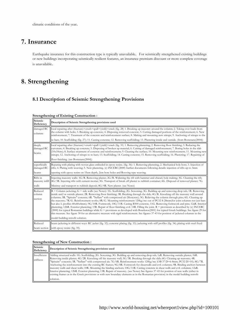
8.1 Description of Seismic Strengthening Provisions Strengthening of Existing Construction :
Strengthening of New Construction :
Seismic Deficiency
Description of Seismic Strengthening provisions used
damaged RC
columns local repairing after (fracture)+crush+spall+(yield)+crack (fig. 28) 1. Breaking up masonry around the column; 2. Taking over loads from the column with bolts; 3. Breaking up concrete; 4. Disposing removed concrete; 5. Cutting damaged portions of the reinforcement; 6. New reinforcement; 7. Treatment of the concrete and reinforcement surface; 8. Making and mounting new stirups; 9. Anchoring of stirups to the
re-bars; 10. Scaffolding (fig. 27); 11. Casting concrete; 12. Removing scaffolding; 13. Plastering inside and outside. (from Bostenaru(2004)) deeply damaged RC
beams
local repairing after (fracture)+crush+spall+(yield)+crack (fig. 31) 1. Removing plastering; 2. Removing floor finishing; 3. Reducing the curvature; 4. Breaking up concrete; 5. Disposing of broken up material; 6. Cutting of damaged reinforcement; 7. Boring holes in the slab (10x10cm); 8. Surface treatment of concrete and reinforcement; 9. Cleaning the surface; 10. Mounting new reinforcement; 11. Mounting new stirups; 12. Anchoring of stirups to re-bars; 13. Scaffolding; 14. Casting concrete; 15. Removing scaffolding; 16. Plastering; 17. Repairing of
floor finishing. (see Bostenaru(2004)) superficially damaged RC
beams
Reparing with plating with woven glass embeded in epoxy resins. (fig. 36): 1. Removing plastering; 2. Mechanical hole bore; 3. Injection of rifts; 4. Plating with weaving; 5. New plastering. (c) INCERC(2000) further documents following details: injection of rifts up to 3mm
opening with epoxy resins on 15cm depth, 2cm bore holes and Rooving type weaving. Rifts in masonry infill
walls
Injecting masonry walls: 1G/R. Removing plaster; 2G/R. Widening the rift with hammer and chiesel, hole making; 3G. Cleaning the rift; 4G/3R. Injecting rifts with cement mortar; 5G. Transport of break off plaster to rubbish container; 6G. Disposal of removed plaster; 7G.
Minitray and transport to rubbish deposit; 8G/4R. New plaster. (see Notes) Reduced column
section
R = Column jacketing; G = side walls (see Notes): 1G. Scaffolding; 2G. Screening; 3G. Building up and removing drop tub; 1R. Removing inside and/or outside plaster; 2R. Removing floor finishing; 3R. Breaking through the slab; 4G/R. Knocking off the masonry wall around columns; 5R. "Spituire" concrete; 6R. "Suflare" with compressed air (Shotcrete); 5G. Relieving the column through pins; 6G. Cleaning up the masonry; 7R/G. Reinforcement works; 8R/G. Mounting reinforcement 120kg/mc out of PC52 8-28mm(for joint columns not just bars but also L profiles 40x40x4mm); 9G/10R. Formwork; 10G/11R. Casting B300 concrete; 11G. Removing formwork and pins; 12aR. Interior plastering; 12bR. Exterior plastering; 13R. Repair of floor finishing; evtl. 14R. Filling the joint. R = provisions as described by (c) INCERC(2000) for typical Romanian buildings while G = provisions as developed with Bourlotos(2001) for typical Greek buildings. See figure 29 for this measure. See figure 30 for an alternative measure with rigid reinforcement. See figures 37-43 for position of jacketed columns in the
model building retrofit solution. Reduced
beam section beam jacketing in different ways: RC jacket (fig. 32); concrete plating (fig. 33); jacketing with stiff profiles (fig. 34); plating with steel fixed
with epoxy resins (fig. 35).
Seismic Deficiency
Description of Seismic Strengthening provisions used
Insufficient
stiffness Adding structural walls: 1G. Scaffolding; 2G. Screening; 3G. Building up and removing drop tub; 1aR. Removing outside plaster; 1bR. Removing inside plaster; 4G/2R. Knocking off the masonry wall; 5G/3R. Breaking through the slab; 6G: Cleaning up masonry; 4R. "Spituire" concrete; 5R. "Suflare" with compressed air; 7G/6R. Reinforcement works 120kg/mc (OB 37 D=6-8mm; PC52 D>10); 8G/7R. Anchoring the reinforcement into the existing RC frames; 9G/8R. Formwork for shearwalls and evtl. columns; 9R. Binding anchors between masonry walls and shear walls; 10R. Mounting the binding anchors; 10G/11R. Casting concrete in shear walls and evtl. columns; 12aR. Interior plastering; 12bR. Exterior plastering; 13R. Repair of masonry. (see Notes) See figures 37-43 for position of new walls (either in existing frames as in the Greek provisions or with new boundary elements as in the Romanian provision) in the model building retrofit
solution.
http://www.world-housing.net/whereport1view.php?id=100101
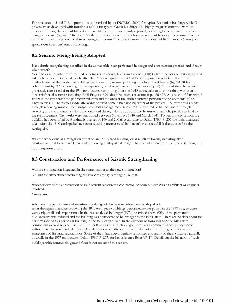
For measures 4, 5 and 7: R = provisions as described by (c) INCERC (2000) for typical Romanian buildings while G = provisions as developed with Bourlotos (2001) for typical Greek buildings. The highly irregular structures without proper stiffening elements of highest vulnerability (see 4.11.) are mainly repaired, not strengthened. Retrofit works are being carried out (fig. 44). After the 1977 the main retrofit method has been jacketing of beams and columns. The rest of the interventions was reduced to repairing of masonry (mainly with mortar injections), of RC members (mainly with epoxy resin injections) and of finishings. 8.2 Seismic Strengthening Adopted Has seismic strengthening described in the above table been performed in design and construction practice, and if so, to what extent? Yes. The exact number of retrofitted buildings is unknown, but from the ones (110) today listed for the first category of risk 92 have been retrofitted totally after the 1977 earthquake, and 43 of them are purely residential. The retrofit methods used at the residential buildings were: masonry repairs, jacketing of columns and beams (fig. 29, 30 for columns and fig. 32 for beams), mortar injections, finishes, epoxy resins injections (fig. 36). Some of them have been previously retrofitted after the 1940 earthquake. Retrofitting after the 1940 earthquake or after bombing was usually local reinforced concrete jacketing. Emil Prager (1979) describes such a measure at p. 426-427. At a block of flats with 7 floors in the city center the perimeter columns and the ones at the corner suffered permanent displacements of 8.5-11cm vertically. The proves made afterwards showed some dimensioning errors of the project. The retrofit was made through replacing some of the damaged columns through metallic columns supported by RC "cuzinet", through jacketing and confinement of the rifted ones and through the retrofit of rifted beams with metallic profiles welded to the reinforcement. The works were performed between November 1940 and March 1941. To perform the retrofit the building has been lifted by 8 hydraulic presses of 100 and 200 tf. According to Balan (1980) P. 235 the main measures taken after the 1940 earthquake have been repairing measures, which haven't even reestablish the state before the earthquake. Was the work done as a mitigation effort on an undamaged building, or as repair following an earthquake? Most works until today have been made following earthquake damage. The strengthening prescribed today is thought to be a mitigation effort. 8.3 Construction and Performance of Seismic Strengthening Was the construction inspected in the same manner as the new construction? No, but the inspection determining the risk class today is thought like that. Who performed the construction seismic retrofit measures: a contractor, or owner/user? Was an architect or engineer involved? Contractor. What was the performance of retrofitted buildings of this type in subsequent earthquakes? After the repair measures following the 1940 earthquake buildings performed rather poorly in the 1977 one, as there were only small scale reparations. In the case analysed by Prager (1979) described above 60% of the permanent displacement was reduced and the building was considered to be brought to the initial state. There are no data about the performance of this particular building in the 1977 earthquake. In the earthquake from 1940 one building with commercial occupancy collapsed and further 8 of this construction type, some with commercial occupancy, some without have been severely damaged. The damages were rifts and breaks in the columns of the ground floor and sometimes of first and second floor. Some of them have been partially retrofitted and many of them collapsed partially or totally in the 1977 earthquake. [Balan (1980) P. 237, further reference Beles(1941)]. Details on the behavior of such buildings with commercial ground floor is not object of this report.
http://www.world-housing.net/whereport1view.php?id=100101
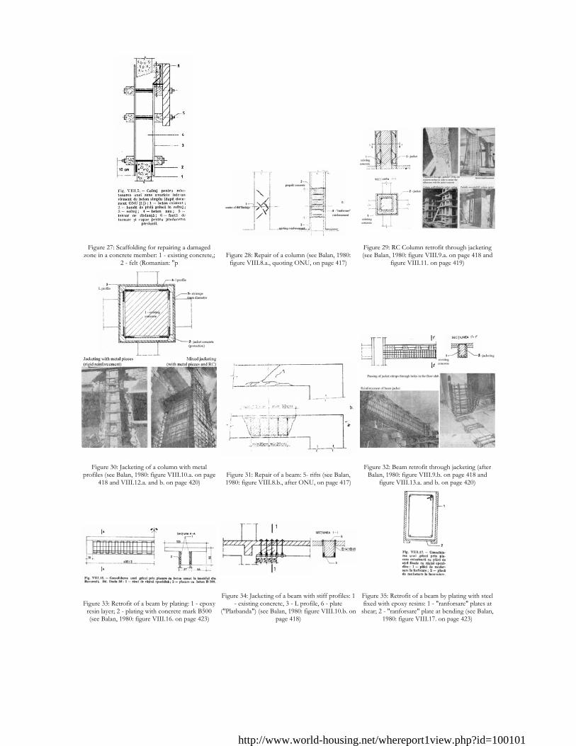
Figure 27: Scaffolding for repairing a damaged
zone in a concrete member: 1 - existing concrete,; 2 - felt (Romanian: "p
Figure 28: Repair of a column (see Balan, 1980:
figure VIII.8.a., quoting ONU, on page 417)
Figure 29: RC Column retrofit through jacketing (see Balan, 1980: figure VIII.9.a. on page 418 and
figure VIII.11. on page 419)
Figure 30: Jacketing of a column with metal
profiles (see Balan, 1980: figure VIII.10.a. on page 418 and VIII.12.a. and b. on page 420)
Figure 31: Repair of a beam: 5- rifts (see Balan, 1980: figure VIII.8.b., after ONU, on page 417)
Figure 32: Beam retrofit through jacketing (after
Balan, 1980: figure VIII.9.b. on page 418 and figure VIII.13.a. and b. on page 420)
Figure 33: Retrofit of a beam by plating: 1 - epoxy
resin layer; 2 - plating with concrete mark B500 (see Balan, 1980: figure VIII.16. on page 423)
Figure 34: Jacketing of a beam with stiff profiles: 1
- existing concrete, 3 - L profile, 6 - plate ("Platbanda") (see Balan, 1980: figure VIII.10.b. on
page 418)
Figure 35: Retrofit of a beam by plating with steel fixed with epoxy resins: 1 - "ranforsare" plates at
shear; 2 - "ranforsare" plate at bending (see Balan, 1980: figure VIII.17. on page 423)
http://www.world-housing.net/whereport1view.php?id=100101
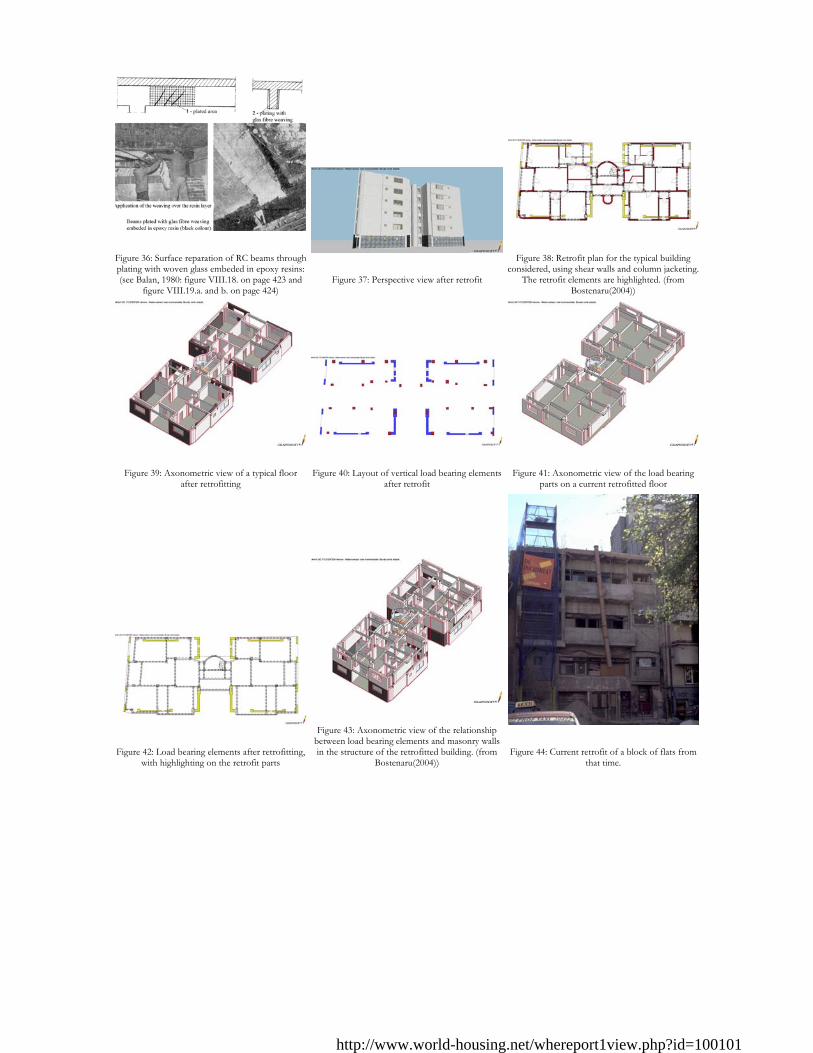
Figure 36: Surface reparation of RC beams through plating with woven glass embeded in epoxy resins: (see Balan, 1980: figure VIII.18. on page 423 and
figure VIII.19.a. and b. on page 424)
Figure 37: Perspective view after retrofit
Figure 38: Retrofit plan for the typical building
considered, using shear walls and column jacketing. The retrofit elements are highlighted. (from
Bostenaru(2004))
Figure 39: Axonometric view of a typical floor
after retrofitting
Figure 40: Layout of vertical load bearing elements
after retrofit
Figure 41: Axonometric view of the load bearing
parts on a current retrofitted floor
Figure 42: Load bearing elements after retrofitting,
with highlighting on the retrofit parts
Figure 43: Axonometric view of the relationship
between load bearing elements and masonry walls in the structure of the retrofitted building. (from
Bostenaru(2004))
Figure 44: Current retrofit of a block of flats from
that time.
http://www.world-housing.net/whereport1view.php?id=100101
Reference(s)
1. The Earthquake and the Constructions Beles,A.A. Buletinul Societatii politehnice din Rom 1941
2. The 1977 March 4, Earthquake in Romania (in Romanian Balan,S. Cristescu,V. and Cornea,I. The Academy of the Socialist Republic of Romania, Bucharest, Romania 1982
3. Architecture projects (1922-1938) Bocanet and Zahariade Simetria publishing house, Union of Romanian Architects and Meridiane publishing house, Romania 1996
4. Economic Efficiency and Applicability of Building Strenghtening Measures for Seismic Retrofit (in German) Bostenaru,M.D. PhD Thesis to be submitted. University of Karlsruhe, Germany 2004
5. Costs estimation in the seismic retrofit of old buildings (in German) Bourlotos,G. Study work at the Institute for Construction Management and Machinery at the University of Karslruhe (TH) 2001
6. A Seismic Damage Assessment Form for Engineered Construction G Earthquake Engineering Research Center, METU, Ankara, Turkey 1994
7. Code for the seismic resistant design of residential, socio-cultural, agro-zootechnical and industrial constructions (in Romanian) INCERC P100-92, MLPAT 1994
8. Problems of building economics (in Romanian) INCERC Edited by INCERC Bucharest, No. 3/2000 2000
9. Earthquake Engineering Research Center: Karl V. Steinbrugge Collection http://nisee.berkeley.edu/visual_resources/steinbrugge_collection.html
10. Development of a methodology for the determination of masonry characteristics. Partial safety factors based on probabilistic models Lungu,D. Research contract No.189/1985 for Building Research Institute (INCERC), Technical University of Civil Engineering Bucharest 1985
11. Study for the development of a methodology for the determination of masonry characteristics Lungu,D. Demetriu,S. and Aldea,A. Research contract No.129/1994 for Building Research Institute (INCERC), Technical University of Civil Engineering Bucharest 1994
Figure 45: Sequences of building construction
shown in the execution program of a building of the same structural type from the same time (1930). "Zidarie de beton simplu" = simple
concrete masonry; "beton armat" = reinforced concrete; "betonarea st
http://www.world-housing.net/whereport1view.php?id=100101
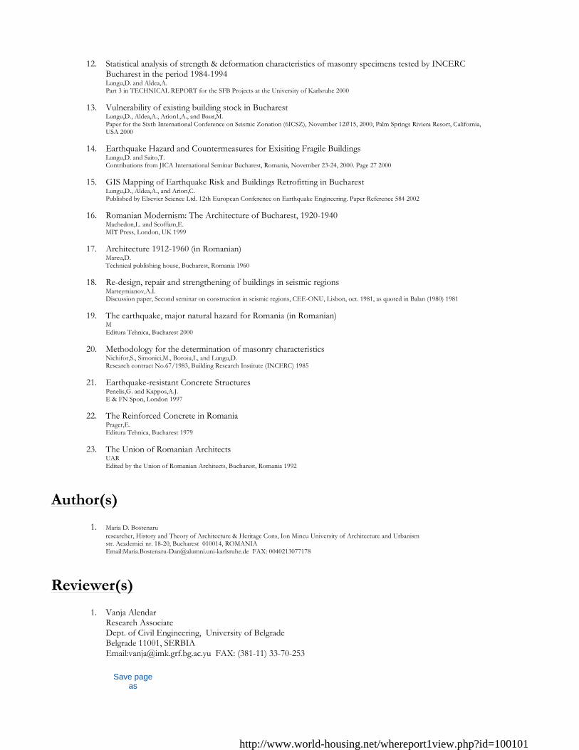
12. Statistical analysis of strength & deformation characteristics of masonry specimens tested by INCERC
Bucharest in the period 1984-1994 Lungu,D. and Aldea,A. Part 3 in TECHNICAL REPORT for the SFB Projects at the University of Karlsruhe 2000
13. Vulnerability of existing building stock in Bucharest Lungu,D., Aldea,A., Arion1,A., and Baur,M. Paper for the Sixth International Conference on Seismic Zonation (6ICSZ), November 12#15, 2000, Palm Springs Riviera Resort, California, USA 2000
14. Earthquake Hazard and Countermeasures for Exisiting Fragile Buildings Lungu,D. and Saito,T. Contributions from JICA International Seminar Bucharest, Romania, November 23-24, 2000. Page 27 2000
15. GIS Mapping of Earthquake Risk and Buildings Retrofitting in Bucharest Lungu,D., Aldea,A., and Arion,C. Published by Elsevier Science Ltd. 12th European Conference on Earthquake Engineering. Paper Reference 584 2002
16. Romanian Modernism: The Architecture of Bucharest, 1920-1940 Machedon,L. and Scoffam,E. MIT Press, London, UK 1999
17. Architecture 1912-1960 (in Romanian) Marcu,D. Technical publishing house, Bucharest, Romania 1960
18. Re-design, repair and strengthening of buildings in seismic regions Marteymianov,A.I. Discussion paper, Second seminar on construction in seismic regions, CEE-ONU, Lisbon, oct. 1981, as quoted in Balan (1980) 1981
19. The earthquake, major natural hazard for Romania (in Romanian) M Editura Tehnica, Bucharest 2000
20. Methodology for the determination of masonry characteristics Nichifor,S., Simonici,M., Boroiu,I., and Lungu,D. Research contract No.67/1983, Building Research Institute (INCERC) 1985
21. Earthquake-resistant Concrete Structures Penelis,G. and Kappos,A.J. E & FN Spon, London 1997
22. The Reinforced Concrete in Romania Prager,E. Editura Tehnica, Bucharest 1979
23. The Union of Romanian Architects UAR Edited by the Union of Romanian Architects, Bucharest, Romania 1992
Author(s)
1. Maria D. Bostenaru researcher, History and Theory of Architecture & Heritage Cons, Ion Mincu University of Architecture and Urbanism str. Academiei nr. 18-20, Bucharest 010014, ROMANIA Email:[email protected] FAX: 0040213077178
Reviewer(s)
1. Vanja Alendar Research Associate Dept. of Civil Engineering, University of Belgrade Belgrade 11001, SERBIA Email:[email protected] FAX: (381-11) 33-70-253
Save page as
http://www.world-housing.net/whereport1view.php?id=100101

http://www.world-housing.net/whereport1view.php?id=100101