hot water floor and space heating - ndsu libraries
TRANSCRIPT

Hot Water Floor and Space Heating
1111111~I~ill~III~llil rllillllll~lrllill'l~11111 Ex ten~~;~~I;r~ u ~t~I~:IV~~~ i neer 3010900511 4320
Hot water heating (sometimes called hydronic heating) is a popular and effective method of heating agricultural buildings. Design and installation guidelines for both floor and space heating systems are included in this publication.
Hot water can be used for a number of heating situations in farm structures, including:
• Space heating of livestock buildings, usually with black steel pipe, finned-tube convectors or hot
,--. water unit heaters. Swine, dairy and poultry buildings lend themselves well to hot water heating systems.
• Floor heating of shops.
• Localized floor heat in swine barns, such as in creep feeding areas, sleeping areas of finishing pens, etc.
• Heated-floor broiler chicken houses.
• Specialized floor heating, such as in honey houses or processing rooms.
• Greenhouse heating, usually with finned-tube convectors or unit heaters to give the greater heating capacity these buildings require.
Hot water space heating offers several advantages for confinement livestock buildings:
• It is easy to heat several areas from one central boiler, with zone control for different temperatures in each area.
• It is safer because clogged air filters and the fire hazard of dust in air ducts and furnaces are eliminated.
• It is compatible with ventilation systems; desirable air flow patterns can be reinforced by correct location of the heating units, and furnace backdrafting due to exhaust ventilation systems is avoided by putting the boiler in a separate room.
• It is usually more efficient and has a lower operating cost than forced air.
• It is easy to clean and maintain ..
The initial cost of a hot water system is often higher than that of other types, particularly when used for smaller one-room buildings. For large buildings with several heating zones, hot water is usually more economical. The system should be designed for each building, and alternatives evaluated to make an objective comparison. Hot water space heating requires more maintenance than some systems. Hot water is ideal for floor heating.
Heating Systems The basic hot water heating system, as illustrated
in Figure 1, consists of the following components:
• water heater or boi ler;
• circulating pump;
• expansion tank;
• distribution piping;
• radiators in the space to be heated - black iron or steel pipe, finned-tube convectors, unit heaters or under-floor pipes;
• controls, valves, temperature and pressure gauges, air bleeding valve, pressure relief valve, and pressure regulator.
1111111111111111111111111111111111111111111111111111111111111111111111111111111111111111111111111111111111111111111111111111111111111111111111111111111111111111111111111111111111
1111111111111111111111111111111111111111111111111111111111111111111111111111111111111111111111111111111111111111111111111111111111111111111111111111111111111111111111111111111111
NDSU EXTENSION SERVICE FEBRUARY 1991
North Dakota State University, Fargo, NO 58105

Heating Units Several types of heaters can be used, ranging from
a small residential heater to a large commercial boiler. Domestic water heaters will satisfy requirements up to about 40,000 BTU per hour (12 kW). They are cheap to install bllt are not likely to last as long as boilers. A circulating pump, expansion tank and controls must be added.
Commercial water boilers are recommended for larger systems. These are designed for high heat output and high flow rates. They will probably give better long-term performance than domestic water heaters. The new high-efficiency "pulse-type" or condensing heaters are also suitable. Coal or woodfired water heaters are also available. Though less convenient, these may be more economical in some situations. Be sure that such boilers are fully equipped with safety and functional controls (see the section on controls).
It is best to place the heater in a separate furnace room with an outside entrance. This avoids backdraft problems caused by exhaust system ventilation fans. The furnace room should have two vents to the outdoors for combustion air, one near the ceiling and one near the floor. Each vent must have at least 0.25 square inches of effective cross-sectional area per 1,000 BTU/hr of heater capacity for natural gas or propane, and 1.5 square inches per 1,000 BTU/hr for oil and solid fuel heaters.
Controls Hot water heating systems should have:
• high-limit water temperature shut-off;
• low-limit water temperature start-up;
• high-limit safety switch;
• low-water-volume safety shut-off;
• pressure relief valve on the heater outlet (located where it will not cause injury if it should blow).
Other controls that may be added are flow switches (important for some types of boilers) and a modu-lating temperature control that works in conjunction with an outside temperature sensor to adjust the heating input to meet demand.
System Design Here is a system design summary followed by de
tails on some of the main components.
• Size the water heater unit to meet the requirement of the building or the particular application (such as floor heat).
• For space heating, select the appropriate size and length of radiator based on the heat required for each room. For floor heating, determine the size and placement of the pipes.
• Layout the system on a plan.
2
• Determine the circulating pump capacity to match the heater size or the individual circuit requirements.
• Identify the required equipment - expansion +\ tank, controls, valves, etc. )
Sizing the Heater The building's heating requirement can be calcu
lated from the insulation level of the building, ventilation rate, livestock heat output, outdoor temperature and other factors. Livestock housing references such as those available from the Midwest Plan Se~vice give general guidelines. These values, usually In terms of heat required per animal, are reliable for most situations. (See the floor heat section for designing floor systems.)
A heating unit should be selected by its net or output rating, not its input. Input is important for gas supply, flue sizing and combustion air supply.
Add 10 to 20 percent capacity as a safety factor. Greatly oversized heating equipment, however, is less efficient than a correctly sized system.
Water Flow Rate Water flow and temperature must be adequate to
provide the desired heat output and to allow for temperature drop through the system. Heat output ,. of pipe convectors and unit heaters depends on .1. water and air temperatures. Most space heating systems are designed for about 200 degrees Fahrenheit water (near boiling). Lower water temperatures require larger radiators or longer heating pipes, cost more, and are less efficient.
Circulating water gives up its heat in the radiator and regains it at the boiler. The flow rate should be sufficient to keep this temperature change within acceptable limits; the higher the flow rate, the lower the change. The change should normally be 18 to 27 F for space heating, and less than 18 F for floor heating (to maintain uniform floor temperatures).
Flow rate, temperature change, and heat output are related by the following formula:
F = 20 ....• Equation [1] (T j • To)
where:
F = flow rate (gal/min.)
o = boiler capacity, or heat given up by the water (1000 BTU/h)
Tj • To = temperature change of water from inlet to outlet of the boiler or radiator (0 F)
Example: What flow rate is required for a 200,000 BTU/h system to; maintain the water temperature change at 20 F? . )
Answer: F = 20 2x200
(T j • To) 20
= 20 gpm

Make sure that the line size is adequate to carry this flow rate, based on the length of each loop, flow in each loop, and pressure loss characteristics of the pipe. Usually, for black steel pipe, the pipe size
,r~ selected for heat output is larger than needed to handle the flow. Long run~ or small pipe sizes should be checked for pressure loss; the calculation requires the use of pressure loss tables and should be done by engineers, equipment suppliers, or others familiar with pressure loss calculations.
Select a circulating pump that provides the desired flow rate at the pressure loss for the entire system. Pressure loss should not exceed 10 feet of head for most systems. It is a good idea to use two pumps connected in parallel in case one should fail, or to have a spare on hand.
Expansion Tank Water expands about 4 percent as it is heated
from room temperature to near boiling. This is accommodated by the expansion tank. Two types are available, a simple gravity tank above the heater, or a pneumatic-diaphragm type as illustrated in Figure 1. Consult the equipment supplier for the correct tank for the system.
Valves should isolate and control all zones or flow circuits. Manually operated valves are sometimes needed to balance the system in multi-zoned installations, for system shut down, or if a thermostat fails. Install valves with unions or flanged connections on both sides of the pump so you can remove the pump for repairs. The same applies to any other piece of equipment that may need servicing.
Other Considerations It is beyond the scope of this publication to pro
vide a complete manual on hot water heat, but the following are some of the details that should be considered. The service of experienced heating contractors or equipment suppliers is valuable in assuring that the right components are in place.
Automatic temperature control and zone control are desirable, using thermostatically controlled flow regulators. Automatic valves regulate the hot water circuit in each room or zone and are actuated by the thermostat for that room. The Circulating pump usually runs continually, and the valves open or close as required. Alternatively, the pump can be started by thermostat or aquastat as one or more zones calls for heat. Multi-speed pumps which increase the flow when needed are also available.
Valves should isolate and control all zones or flow circuits. Manually operated valves are sometimes needed to balance the system in multi-zoned installations, for system shut down, or if a thermostat fails. Install valves with unions or flanged connections on both sides of the pump so you can remove the pump for repairs. The same applies to any other piece of equipment that may need servicing.
If the pipe is larger than the flow requires (as is often the case for bare pipe systems), know the flow rate and select a valve of the required capacity. Valves can usually be one or two sizes smaller than the line they serve.
1 Manual valve 2 Thermostatically controlled zone valve 3 Supply line 4 Flue and draft hood 5 Return line 6 Air vent 7 Circulating pump, flange mounted 8 Pressure regulator 9 Check valve
10 Drain valve 11 Temperature gauge 12 Combustion controls 13 Safety relief valve 14 Air purger 15 Expansion tank 16 Water supply
Figure 1. Typical hot water heating system. Inlet and outlet location vary with different makes of equipment.
3

Draining and venting are facilitated if heating lines slope uniformly to one end (or one point). Install drain cocks at the low points and air vents at the high pOints. One of each may be all that is required for simple systems; others may require several.
Antifreeze and corrosion protection is important. Antifreeze should be used if there is any danger of freezing. Use an ethylene glycol solution or other fluids specially formulated for hot water heating systems. These contain corrosion inhibitors to maintain long-term performance of systems and components. Check the antifreeze solution every year and add inhibitor if needed. Most chemical suppliers provide this service.
Automotive antifreeze can be used but is not recommended because it must be replaced every two to three years. Automotive corrosion inhibitors lose their effectiveness, and cannot be replenished. Soft or demineralized water can also be used, with corrosion inhibitors, if there is no danger of freezing.
Thermometers and pressure gauges are handy for balancing the system; however, aside from thermometers on the return and supply side of the boiler, other permanent in-line gauges are not required. Pressure gauge cocks and thermometer wells can be installed at appropriate locations to check out the system.
Expansion and contraction take place as the system warms and cools. Consider this when choosing supports and planning layout. Provide sleeves or adequate clearance where pipes pass through walls or floors. Pipe supports should allow movement.
Allow for expansion at the end of a long pipe line or loop by stopping short of the end wall. For a 180 F change in temperature, steel expands 0.12 percent in length; various plastics expand 5 to 15 times as much.
A pressure regulator is necessary on the water supply connection. Most systems work best under a moderate pressure of about 15 psi for better circulation and to avoid vapor locks. A backflow preventer is also needed.
Two-Temperature Systems Two water temperatures may be needed in
livestock barns. Floor heat requires water at about 115 F, while space heating requires water at 195 F. You have three options:
(1) Use two separate systems. This may be best for large multi-room buildings.
(2) Install an in-line water-to-water heat exchanger that will take heat from the main system to warm the floor water to the desired temperature.
(3) Use a thermostatic mixing valve, called a tempering valve, to blend hot water into the floor circuit to maintain the desired temperature.
4
The first method allows for the completely independent operation of each system - for example, if space heating is shut down for the summer the floor heat system may continue to operate.
The last two methods require a separate circulating pump for the floor heating circuit. Consult suppliers of this specialized equipment for installation details.
Floor Heating Floor heating is accomplished by circulating hot
water through lines of high temperature (160 F) plastic or copper pipe, placed either in sand below the floor or in the concrete. Floor heat is used in wellinsulated buildings such as farm shops and in livestock housing for creep or weaner pig areas. Figure 2 illustrates a typical shop floor installation. Figure 3 shows details for a swine barn.
Systems are designed using the same principles as for space heating and most of the equipment is the same: heater or boiler, circulating pump, expansion tank, valves and controls. The following com· ments are specific to floor heating:
Water temperature Temperature can be much lower for floor heat than for space heating, 100 to 140 F rather than 195 F. The floor temperature of a large area is best controlled by regulating the water temperature, rather than by starting or stopping the flow. Control of small sections, such as in baby pig creeps, may be more precise and adjustable if line • thermostats regulate flow to each section. Water temperature will be 18 to 27 F warmer than the floor when pipes are placed in the concrete, and about 45 F warmer when they are in the sand below.
It is often useful to know the floor temperature. One way to do this is to make thermometer wells in the concrete. An ordinary thermometer (or electronic temperature probe) in contact with the floor can measure temperature directly. It works best if covered with a small slab of foam insulation so it is kept at floor temperature. Cut a small groove in the insulation so it fits over the thermometer.
The following is a guide to heating levels for various farm applications:
, Floor Temperature Heat Output
(OF) (0C) (WIfe) (BTUlft2·h)
Shop floors 77-86 25·30 14·20 50·68 Pig nursery barns 70·85 21·29 10·20 34·68 Baby pig creeps 85·95 29·35 20·25 68·85
Piping usually is plastic. Polybutylene pipe, made for hot water, is recommended. Higher strength, 125 psi polyethylene can also be used, as well as soft copper tubing. Connections should be made outside ) the floor using double stainless steel clamps. Polybutylene pipe can also be fusion joined.

\.
----------------------, ---------------------)
---------------------, __ - - - _________________ ----..I
1r11r---~ ___ ., -- -- -- -- -- - -- --- - - - - - - -- ,
----- -------------- - -_/
----------------------- '\
------ - - - - --------------, --------------- --------/
Detail A
1 Boiler unit; approximately 63 btu/ft2 (18 w/ft2)
2 Supply and return lines in sand layer beneath concrete floor; 0.75 in. @ 12-16 in. o.c.
3 8 x 8 in. combustion-air vent
4 Insulated concrete foundation
------- -, -- -- --- -- -- /
-- -- -- -------, --------- ----/
Detail B
5 Concrete floor 6 6 mil. vapor barrier and 2 in. rigid
extruded polystyrene insulation
7 Header pipe with T-fittings 8 Manual valve on each loop
9 Nipples for clamp to attach floor pipe
Figure 2. Shop floor heating installation.
5

II II
: : II
Ii:
i i II Ij
Plan view '-Weaner area
Creep area 2 Slotted floor 3 Solid floor 4 Return line 5 Supply line: from boiler to other heat
source 6 Thermostat 7 Flow control valve: in main return line
or in loop return line - NOT BOTH 8 Mounting bracket
Detail of installation
9 Manual valve 10 Supply line 11 Conduit or plastic
protection at floor 12 Return line 13 Concrete floor 14 Sand layer 15 Rigid insulation 16 Sensing bulb in metal
conduit filled with oil
Retu rn Pipe~r--. Return Pipe
2" ri tion pipe cree
Floo Pipe
gid insula-over between
ps.
r~
Return Pipe
2" rigid insulation over pipe under sow.
Floor Heat Pipe
1 c - -I
lY I
U I I I
I I ,
~ ,
I I , I , L_
- -r I I I ,
U I , I I
I I
I I I
I I I I I I L __ ~
-, I I I I I I I , I , LI-
~-"'--::-::r:::-==""'T'--:-r:-==-=""",,,...,.--r-I 2" ri g id ins u lation over pipe between creeps.
- Floor Heat Pipe
L.----~ Floor Heat Pipe
Figure 3_ Swine barn floor heating installation.
6
•
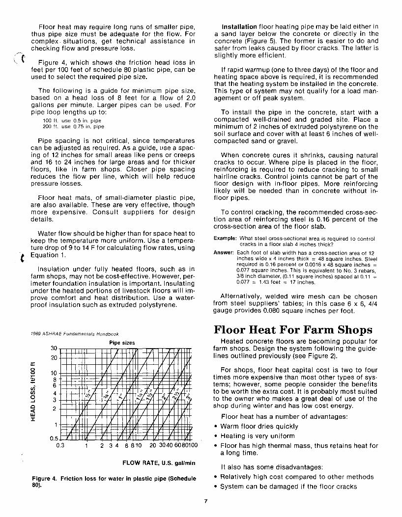
Floor heat may require long runs of smaller pipe, thus pipe size must be adequate for the flow. For complex. situations, get technical assistance in checking flow and pressure loss.
Figure 4, which shows {he friction head loss in feet per 100 feet of schedule 80 plastic pipe, can be used to select the required pipe size.
The following is a guide for minimum pipe size, based on a head loss of 8 feet for a flow of 2.0 gallons per minute. Larger pipes can be used. For pipe loop lengths up to:
100 ft. use 0.5 in. pipe 200 ft. use 0.75 in. pipe
Pipe spacing is not critical, since temperatures can be adjusted as required. As a guide, use a spacing of 12 inches for small areas like pens or creeps and 16 to 24 inches for large areas and for thicker floors, like in farm shops. Closer pipe spacing reduces the flow per line, which will help reduce pressure losses.
Floor heat mats, of small-diameter plastic pipe, are also available. These are very effective, though more expensive. Consult suppliers for design details.
Water flow should be higher than for space heat to keep the temperature more uniform. Use a temperature drop of 9 to 14 F for calculating flow rates, using
t Equation 1.
Insulation under fully heated floors, such as in farm shops, may not be cost-effective. However, perimeter foundation insulation is important. Insulating under the heated portions of livestock floors will improve comfort and heat distribution. Use a waterproof insulation such as extruded polystyrene.
1989 ASHRAE Fundamentals Handbook
--0 0
§ en C/)
0 ...J
0 « w :I:
30
20
10 8 6 4 3 2
0.5 0.3
,""' ,,\y
V
Pipe sizes
I / I II I
/ V I
I'-t-
J~~/- / ~~ r-""I-, ~ " "~_""L .... yt- ~ ">,t
IL IL I /
V / 1/
/ V V /
2 3 4 6 810 20 30406080100
FLOW RATE, U.S. gal/min
Figure 4. Friction loss for water in plastic pipe (Schedule 80).
7
Installation floor heating pipe may be laid either in a sand layer below the concrete or directly in the concrete (Figure 5). The former is easier to do and safer from leaks caused by floor cracks. The latter is slightly more efficient.
If rapid warmup (one to three days) of the floor and heating space above is required, it is recommended that the heating system be installed in the concrete. This type of system may not qualify for a load management or off peak system.
To install the pipe in the concrete, start with a compacted well-drained and graded site. Place a minimum of 2 inches of extruded pOlystyrene on the soil surface and cover with at least 6 inches of well· compacted sand or gravel.
When concrete cures it shrinks, causing natural cracks to occur. Where pipe is placed in the floor, reinforcing is required to reduce cracking to small hairline cracks. Control jOints cannot be part of the floor design with in-floor pipes. More reinforcing likely will be needed than in concrete without infloor pipes.
To control cracking, the recommended cross-section area of reinforcing steel is 0.16 percent of the cross-section area of the floor slab.
Example: What steel cross·sectional area is required to control cracks in a floor slab 4 inches thick?
Answer: Each foot of slab width has a cross·section area of 12 inches wide x 4 inches thick = 48 square inches. Steel required is 0.16 percent or 0.0016 x 48 square inches = 0.077 square inches. This is equivalent to NO.3 rebars, 3/8 inch diameter, (0.11 square inches) spaced at 0.11 "'" 0.077 = 1.43 feet = 17 inches.
Alternatively, welded wire mesh can be chosen from steel suppliers' tables; in this case 6 x 6, 4/4 gauge provides 0.080 square inches per foot.
Floor Heat For Farm Shops Heated concrete floors are becoming popular for
farm shops. Design the system following the guidelines outlined previously (see Figure 2).
For shops, floor heat capital cost is two to four times more expensive than most other types of systems; however, some people consider the benefits to be worth the extra cost. It is probably most suited to the owner who makes a great deal of use of the shop during winter and has low cost energy.
Floor heat has a number of advantages:
• Warm floor dries quickly
• Heating is very uniform
• Floor has high thermal mass, thus retains heat for a long time.
It also has some disadvantages:
• Relatively high cost compared to other methods
• System can be damaged if the floor cracks

Grade level
P.P.T. Plywood
Perimeter insulation Extend to bottom of footing
Grade level P.P.T. Plywood
E :::l
E c
Perim insulation § Extend to ~ bottom of ~ footing
A Below concrete floor
B In concrete floor
Supply and return lines Pipe 12 in.· 16 in. o.c.
Supply and return lines Pipe 12 in .. 16 in. o.c.
Reinforcing mesh
Figure 5. Installation of floor heating pipe.
8

(~
(I
- Slow to react to sudden changes in demand (large door opened, large cold machine brought in)
- Not suitable for occasional use.
The most serious drawback to floor heat is slow reaction time. It will be nepessary to have a supplementary space heater (separate unit heater or furnace) for quick response when cold-weather servicing is critical.
System Design The best floor temperature is 77 to 86 F; warmer
floors are uncomfortable and cooler ones are less effective. The amount of heat transferred from the concrete floor to the shop depends on both floor and the air temperatures. Heat input to the floor will depend on the inlet water temperature, pipe spacing and water flow, provided that the heating unit has enough capacity to keep up to the floor heat loss.
Heat output from floor to air is given by the following equation:
o = 2.11 (Tf - T a) ........................... Equation [2] where 0 = heat output from the floor, BTU/ft2.h
Tf = floor slab temperature, 0 F T a = room air temperature, 0 F
For a floor at 86 F and air temperature of 59 F, heat output would be 2.11 x 27 F = 57 BTU/ft2-h. As the building cools below 59 F, the heat output will increase accordingly. Design for 60 BTU/ft2-h and size the heating unit slightly larger to account for system losses.
It is possible to get by with a small heating unit, down to about 44 BTU/ff-h, if cooler floors are acceptable. On the other hand, the system will have to be larger if auxiliary unit heaters are supplied from the same boiler system.
This heat output will keep a reasonably well-insulated shop at 50 to 60 F but does not have extra capacity for reserve heat.
Water flow and pump capacity are calculated as outlined earlier (Equation 1), using a temperature change of 9-14 F to maintain uniform conditions. Floor heating pipe is usually placed in loops running from a supply and back to a return header (see Figure 2). Flow through each loop is the total flow divided by the number of loops. Pipe may also be laid out in a continuous spiral around the building but this will require larger pipe due to the longer loop length.
The header system is normally pipe with T-fittings or nipples for attaching the floor lines. The header should be sized for the total water flow in the system. Valves are recommended on each floor line to
( balance or control flow; one on the supply and another on the return are best in case one loop springs a leak. Estimated minimum header pipe size is shown in Figure 6.
9
Example: Design a floor heating system for a shop 32 feet x 50 feet (Figure 2). Floor area inside the foundation is about 32 x 50 = 1600 square feet.
1. Calculate system size based on 60 BTUlft2.h heat input: 60 BTU/ft2·h x 1600 ft2 = 96,000 BTU/h
= 28 kW heating units 3413 BTU/h = 1 kW
2. Determine flow rate for a temperature change of 11 F across the system, using equation 1: F = 20 0 = 96 kBTU-h
(T; - To) T; - To = 11 0 F
F = 2x96 = 17.5gpm 11
3. Each loop is about 105 feet long, so 0.5 inch pipe will be adequate (for this small shop, double loops of 210 feet length could be run to reduce valves and connections).
Shop width = 32 ft. Pipe spacing = 18 in. = 1.5 ft. Number of lines = 32 .;- 1.5 = 21.3 Therefore, use 22 lines or 11 loops
Water flow in each loop = 17.5 gpm = 1.59 gpm 11
Length of Pipe (ft)
Using the next larger size will reduce the required system pressure.
Figure 6. Estimated minimum header pipe size.

4. Size the header system lor allow 0118 gpm. 2·inch pipe is adequate.
5. Estimate the volume of the system 1155 It. 01 0.50 in. Iloor pipe x 0.010 gal/It. = 11.6 gal 70 It. 01 2 in. header x .174 = 12.2 Boiler unit volume (estimated) = 3.0
Total = 26.8 gal
Minimum expansion capacity required is 5 percent 01 26.8 = 1.34 gal.
Obtain an expansion tank with at least 1.5 gal. expansion capacity.
Livestock Floor Heating Apply the same installation and design principles
used with other floor heat systems. More complex control systems may be required for some installations, particu larly where several floor sections are heated by one system.
Figure 3 illustrates some typical farrowing barn systems and some methods of installation and controL
The simplest method is to supply all floor areas with the same water at about 115 F. The baby pig creep areas, if insulated, will be 4 to 9 F warmer than the weaner floors. This works, but the floor may still be warmer than desired. The valve to that floor circuit could be closed down to regulate temperature.
Note that the control valve could be on the main line serving both creep areas, or there could be a separate valve and thermostat for each creep. The latter is best if several creep areas are supplied by one main line. Accurate floor temperature regulation is obtained by using floor thermostats, as illustrated in Figure 7. Thermometer bulbs or electronic sensors can be used.
Insulating under and beside creep floors will concentrate the heat, improving the baby pigs' comfort without overheating the sow. Insulation is less important for large heated pen areas. There should be no floor heat under the sow. In operating heated floor barns, it is desirable to measure floor temperature to be sure equipment is working and as a guide for making adjustments.
Space Heating Radiators
These are the elements that transfer the heat from the hot water to the air in the room. Black steel pipe, finned-tube convectors, and fan-forced hot water unit heaters are the main types. Figure 8 shows some types and their application.
Black steel pipe. Most commonly used in livestock buildings, this is easy to clean, least affected by dust, and not easily damaged. Bare pipe is more
10
Heat Pipe
'" Conduit
Large Radius 90° Elbow or 2-45° Elbows
min 2" Rigid Waterproof Insulation
Figure 7. Thermostat installation.
costly and requires more labor to install than finned· tube convectors because it is larger and more pipe is required. Galvanized pipe should not be used since the galvanizing restricts heat transfer.
Black steel pipe is usually mounted under air in-lets or on wall brackets. Pipe radiators should be mounted at least one pipe diameter from the wall to permit free air circulation. Heat output for bare steel pipe and the length of pipe needed can be determined from Table 1. Table 1 also contains a volume measurement for determing the amount of fluid J needed to fill the system.
Table 1. Heat output from standard (schedule 40). Bare steel pipe (W/m or BTU/heft)"
Nominal Temp. difference between pipe size pipe and surrounding air Pipe volume
40 50 60 70 80 90°C mm(in.) 72 90 108 126 144 162°F LIm (gallft)
13 0.50 0.12 0.010 19 0.75 0.28 0.023 25 1.0 55 70 90 110 130 150 0.56 0.045 32 1.25 70 90 110 135 160 190 0.97 0.078 38 1.5 80 100 130 160 185 220 1.32 0.106 50 2.0 100 120 160 190 220 260 2.16 0.174 75 3.0 150 180 220 270 320 380 4.77 0.384
• Note: 1.0 W/m = 1.04 BTU/h·It). which is nearly equal. In this table, nominal pipe size refers to the approximate inside diameter, and volume is given in U.S. gallons, as this measure is used in most equipment specifications.
Example: What length 01 2 in. black pipe is required to input 100,000 BTU/hr. (30W) 01 heat into a grower pig barn maintained at 60 F (15 C), il the average hot water temperature is 185 F (85 C)?
Answer: The temperature difference is 185 F· 60 F = 125 F. From the table read a heat output 01 190 BTU/hreft lor 2 in. pipe. Pipe length required is 100,000 BTU/hr. -;- 190 BTU/heft = 526 It. Four lines (two loops) would be typical.
Allow for expansion and contraction of the pipe as {: temperatures change.

'.
2 Finned-tube convectors
1 Fan-forced hot water unit heater 3 Black steel pipe application
Figure 8. Radiators.
Finned·tube convectors. These have four to five times the heat transfer capacity per foot of length as Jare pipe. Output varies with fin size and spacing, so ~onsult equipment suppliers for design data. They He particularly suitable for small rooms or green· louses where there is not enough room for bare )ipe. Where less heat is required, short sections of ~onvector can be spaced along a wall.
The main drawbacks to finned·tube systems are hat they collect dust (reducing performance), reluire frequent cleaning and can easily be damaged. -hey are not recommended for dusty livestock build· ngs. Corrosion is also a problem in livestock barns.
11
Hot water unit heaters. These are excellent for small rooms for livestock, shops, milkhouses, calf pens and similar areas where a concentrated heat source is desired. They can also be incorporated with ventilation air ducts or other types of air circulation systems. In dusty buildings, these radiators should be inspected and cleaned regularly to main· tain heating effectiveness.
Acknowledgement Canada Plan Service Plan M-9735 "Hot Water
Floor and Space Heating" was the primary source of information for this publication.

Helping You Put Knowledge To Work NDSU Extension Service, North Dakota State University of Agriculture and Applied Science, and U.S. Department of Agriculture cooperating. William H. Pietsch, Director, Fargo, North Dakota. Distributed in furtherance of the Acts of Congress of May 8 and June 30, 1914. We offer our programs and facilities to all persons regardless of race, color, sex, religion, age, national origin, or handicap; and are an equal opportunity employer. 2.5M.3.9~