host communications protocol instruction manual€¦ · host communications protocol barber-colman...
TRANSCRIPT
1640-IN-025-A-05 Page 1 of 56
Host Communications Protocol
Barber-Colman Company, Loves Park, IL
Instruction Manual
Table of Contents
Contents1. Introduction ............................................................................................... 3
1.1 Multi-Chassis Addressing.............................................................. 32. MACO Serial Communication Setup ......................................................... 3
2.1 COMM Setpoints ........................................................................... 42.2 Baud Rate Setpoints ..................................................................... 42.3 Port Control Relay Status ............................................................. 5
3. RS-232 Host Communications .................................................................. 53.1 Hardware Requirements ............................................................... 53.2 Control Relays............................................................................... 5
3.2.1 Inhibit Remote Access (CR 649) ........................................... 53.2.2 Enable Remote Setpoint Change (CR 650) ........................... 53.2.3 Enable Remote CR Change (CR 651) ................................... 5
3.3 Wiring ............................................................................................ 53.4 Establishing Data Acquisition ........................................................ 73.5 Request Data Commands ............................................................. 73.6 Error Reply to Request Data Command ....................................... 83.7 Reply to Valid Request Data Command ....................................... 93.8 Send Data Commands ................................................................ 113.9 MACO Error Reply to Send Data Command............................... 133.10 Reply to Valid Send Data Command .......................................... 133.11 Changing to the File Transfer Mode ........................................... 143.12 Insertion of <DLE> ...................................................................... 143.13 Determining Error Code Definitions ............................................ 14
3.13.1 Error Code Definitions ......................................................... 15 4. RS-485 Host Communications ................................................................ 25
4.1 Hardware Requirements ............................................................. 254.1.1 Editor Requirements ............................................................ 254.1.2 Switch Definitions ................................................................ 26
4.1.2.1 Switches 1 - 6 Node Address (UID) ................................ 264.1.2.2 Switch 7 Save Configuration ........................................... 264.1.2.3 Switch 8 Data Update ..................................................... 27
4.1.3 Communication Board Location ........................................... 274.2 General Setup Procedure ........................................................... 27
4.2.1 Control Relays ..................................................................... 274.3 Wiring .......................................................................................... 284.4 Module Setpoints ............................................................................. 28
4.4.1 Baud Rate Setpoint .............................................................. 284.4.2 COMMODE Setpoint ........................................................... 284.4.3 Clear Data Valid Timer ........................................................ 28
4.5 Module Values ............................................................................ 284.5.1 Block Value 1 - Block Value 10 ............................................ 284.5.2 Number of Setpoints ............................................................ 284.5.3 Number of Values ................................................................ 294.5.4 Switch Value ........................................................................ 29
4.6 Module Control Relays ................................................................ 294.6.1 Trigger Control Relay (CR 3753) ........................................ 294.6.2 HOST Control Relay (CR 3754) .......................................... 294.6.3 Data valid Control Relay (CR 3765) .................................... 29
1640-IN-025-A-05 Page 2 of 56
Host Communications Protocol
Barber-Colman Company, Loves Park, IL
4.7 Module Error Codes .................................................................... 294.7.1 Data Handler Error Code Messages .................................... 30
4.8 Command Structure .................................................................... 305. RS-485 Command Codes ....................................................................... 32
5.1 Command #1 — Download Menu Parameters ........................... 325.1.1 Example Command #1 ........................................................ 33
5.2 Command #2 — Request Upload of Block Data ......................... 345.2.1 Example Command #2 ........................................................ 34
5.3 Command #3 — Setpoint Change .............................................. 355.3.1 Example #1 Command #3 ................................................... 355.3.2 Example #2 Command #3 ................................................... 36
5.4 Command #6 – Request Data Valid Status ................................ 365.4.1 Example Command #6 ........................................................ 37
5.5 Command #7 – Clear DATA VALID ............................................ 385.5.1 Example Command 7 .......................................................... 38
5.6 Command #8 – Individual Setpoint/Value Request .................... 385.6.1 Example Command #8 ........................................................ 38
5.7 Command #9 – Control Relay ..................................................... 395.7.1 Example Command #9 ........................................................ 40
5.8 Command #10 – Request ASCII String ...................................... 405.8.1 Ex. Cmd #10 – ASCII String Request (Type Upper = 4XH). 415.8.2 Ex. Cmd #10 – ASCII String Request (Type Upper = 3XH). 42
5.9 Command #11 – Change Control Relays ................................... 435.9.1 Example Command #11 ...................................................... 43
5.10 Command #12 – File Access – Read File ................................... 445.10.1 Example Command #12 ...................................................... 46
5.11 Command #13 – File Access– Write File .................................... 485.11.1 Example Command #13 ...................................................... 49
5.12 Command #14 – Request Host Monitor Error Table ................... 515.12.1 Example Command #14 ...................................................... 51
5.13 Command #15 – Data Handler Host Command ............................. 525.13.1 Example Command #16 ...................................................... 52
FiguresFigure 1. Serial Communications Setup Screen .......................................... 4Figure 2. RS-232 Host Communication Module ........................................... 5Figure 3. Standard Serial Cables ................................................................ 6Figure 4. RS-485 Host Communication Module ......................................... 25Figure 5. Wire Multiple MACO's ................................................................. 27
TablesTable 1. File Types.................................................................................... 45Table 2. Host System Commands ............................................................ 53Table 3. ASCII to Hex to Decimal Conversions ........................................ 56
1640-IN-025-A-05 Page 3 of 56
Host Communications Protocol
Barber-Colman Company, Loves Park, IL
1. IntroductionThe MACO 4000, 5000 and 6000 Series systems provide a host communicationoption using either an RS-232 or RS-485 host communication module to link thecontrol system to a host computer, allowing full Supervisory Control and DataAcquisition (SCADA) over a standard network platform. When fitted with a MACORS-485 host communication module, a MACO controlled machine can be at-tached to a network of up to 32 devices on a single serial port of a host computerCommunications can be used to collect, display and store operating data, as wellas transmit setpoints or change control relays in the MACO controllers.
1.1 Multi-Chassis AddressingEach controller of a multi-chassis system has its own set of control relay (CR)system addresses. The control relay addresses shown in this manual reflect theaddresses used for Controller 1 (the “primary” controller).
Almost all control relays repeat in a multi-chassis system. The few exceptionsrelate to recipes, some SPC items (data handler modfile), print CRs, switch LEDCRs (sequence modfile), status CRs from the display processor, data handler, RS-232 host communications, and RS-485 host communications modfiles. Refer tothe control relay tables for a complete list of control relays.
The control relay table contains a column headed “Multi-Chassis Addressing?”.Those control relays which have a “Yes” entry in that column can be written intothe RLD if a multi-chassis system is being utilized. With the exception of controlrelay addressing, multi-chassis operation is transparent to the RLD. All download-ing and recipe storage is to Controller 1. “Enabling” relays which relate to systemoperation (recipe saving and reading, setpoint change, etc.) must be enabled inEACH chassis. Machine function keys and RS-232/Printer/RS-485 functions areonly in Controller 1.
Note: When counting boards in multi-chassis systems (for switch settings, RLD/screen programming) count each control rack separately. For example, if a multi-chassis system consists of two control racks, each with two temperature boards,EACH controller would have a Temperature Board #1 and a Temperature Board#2. The same numbering scheme holds true for all types of boards (including Inputand Output boards).
Note: Currently the host communications can only communicate with Controller#1 (the primary chassis).
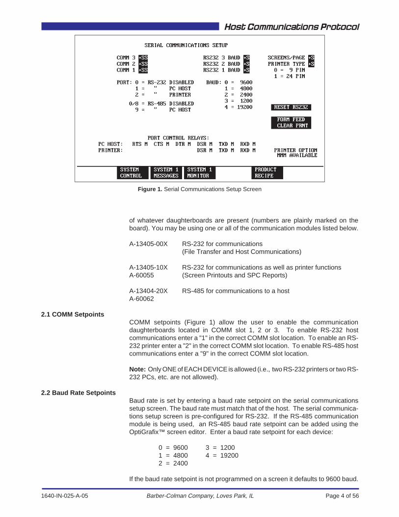
2. MACO Serial Communication SetupThe MACO serial communications setup screen (Figure 2.0) is used for settingbaud rates and enabling communications. This controller can have as many asthree separate external devices connected for use with serial communications.Daughterboards purchased for the communications motherboard determine whattype of device can be connected. The COMM numbers correspond to daughterboardlocations on the motherboard:
COMM 3 Upper SlotCOMM 2 Middle SlotCOMM 1 Bottom Slot
Examine the communications motherboard and determine the type and location
1640-IN-025-A-05 Page 4 of 56
Host Communications Protocol
Barber-Colman Company, Loves Park, IL
of whatever daughterboards are present (numbers are plainly marked on theboard). You may be using one or all of the communication modules listed below.
A-13405-00X RS-232 for communications(File Transfer and Host Communications)
A-13405-10X RS-232 for communications as well as printer functionsA-60055 (Screen Printouts and SPC Reports)
A-13404-20X RS-485 for communications to a hostA-60062
2.1 COMM SetpointsCOMM setpoints (Figure 1) allow the user to enable the communicationdaughterboards located in COMM slot 1, 2 or 3. To enable RS-232 hostcommunications enter a "1" in the correct COMM slot location. To enable an RS-232 printer enter a "2" in the correct COMM slot location. To enable RS-485 hostcommunications enter a "9" in the correct COMM slot location.
Note: Only ONE of EACH DEVICE is allowed (i.e., two RS-232 printers or two RS-232 PCs, etc. are not allowed).
2.2 Baud Rate SetpointsBaud rate is set by entering a baud rate setpoint on the serial communicationssetup screen. The baud rate must match that of the host. The serial communica-tions setup screen is pre-configured for RS-232. If the RS-485 communicationmodule is being used, an RS-485 baud rate setpoint can be added using theOptiGrafix™ screen editor. Enter a baud rate setpoint for each device:
0 = 9600 3 = 12001 = 4800 4 = 192002 = 2400
If the baud rate setpoint is not programmed on a screen it defaults to 9600 baud.
Figure 1. Serial Communications Setup Screen
1640-IN-025-A-05 Page 5 of 56
Host Communications Protocol
Barber-Colman Company, Loves Park, IL
2.3 Port Control Relay StatusThe port control relays listed at the bottom of the communication setup screenindicate the status of any ongoing communications. For an RS-232 device anasterisk will indicate the status of each line. The asterisk will indicate if data isbeing transmitted or received (these are not “real time” indicators - they are meantonly to show that communication is taking place).
3. RS-232 Host CommunicationsThe MACO RS-232 host communication module allows you to attach your MACOcontrolled machine to a single serial port of a host computer that will collect, displayand store operating data, as well as transmit setpoints to the MACO controllers.
3.1 Hardware RequirementsThe RS-232 host communication module (daughterboard) resides in one of theslots of the communication motherboard. There are no hardware jumpers orswitch settings used with the RS-232 host communication module. Simply mountthe host communication module to the motherboard.
The communications motherboard must be installed in Primary Chassis 1 in a slotwhich has a control data bus connector (the middle connector on the back-planeof the MACO controller).
3.2 Control RelaysBefore attempting to establish communications between the Host and the MACO,make certain to enable or disable the CRs appropriate for your application. If theCRs listed below are not set correctly, change them in the RLD logic using the RLDEditor software program.
3.2.1 Inhibit Remote Access (CR 649)Control relay 649 is used to inhibit remote access such as from a personalcomputer to the MACO controller. With this relay energized, the MACO controllerwill not accept any changes from a remote device.
3.2.2 Enable Remote Setpoint Change (CR 650)Control relay 650 is used to enable remote setpoint changes. This control relaymust be energized (and control relay 649 must be de-energized) in order to makesetpoint changes from a remote device.
3.2.3 Enable Remote CR Change (CR 651)Control relay 651 is used to enable remote control relay changes. This controlrelay must be energized (and control relay 649 must be de-energized) in order tomake control relay changes from a remote device.
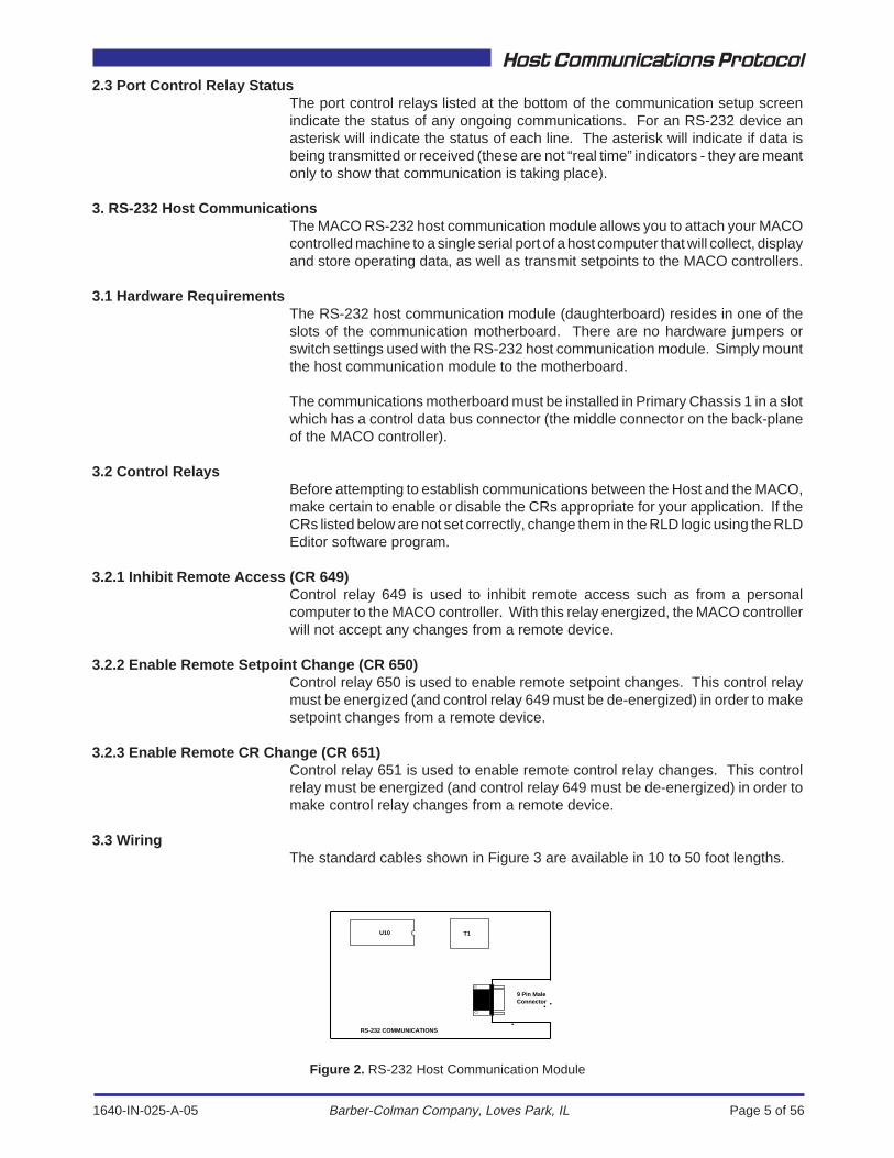
3.3 WiringThe standard cables shown in Figure 3 are available in 10 to 50 foot lengths.
Figure 2. RS-232 Host Communication Module
U10
RS-232 COMMUNICATIONS
T1
9 Pin MaleConnector

1640-IN-025-A-05 Page 6 of 56
Host Communications Protocol
Barber-Colman Company, Loves Park, IL
123456789
DCDRXDTXDDTRSGDSRRTSCTSRI
BlackWhiteRedGreenBrownBlueOrangeYellowPurple
123456789
DCDRXDTXDDTRSGDSRRTSCTSRI
BlackWhiteRedGreenBrownBlueOrangeYellowPurple
123456789
DCDRXDTXDDTRSGDSRRTSCTSRI
BlackWhiteRedGreenBrownBlueOrangeYellowPurple
182367205422
A-13709-000-0-XXCable Assembly
Female DB9 to Unterminated
A-13709-100-0-XXCable Assembly
Female DB9 to Female DB9
A-13709-200-0-XXCable Assembly
Female DB9 to Female DB25
DB9
DB9
DB9
DB9
DB25
Shield
Shield
Shield
132654879
DCDTXDRXDDSRSGDTRCTSRTSRI
DCDTXDRXDDSRSGDTRCTSRTSRI
Chassis Gnd
*
(XX = No. of Ft.)
(XX = No. of Ft.)
(XX = No. of Ft.)
Figure 3. Standard Serial Cables
123456789
DCDRXDTXDDTRSGDSRRTSCTSRI
Red
BlackGreen
1
3
720
A-13709-400-0-XXCable Assembly
Female DB9 to Male DB25(Serial to Parallel
Converter)
(XX = No. of Ft.) DB9 DB25Shield
RXD
SGDTR
Chassis Gnd
1640-IN-025-A-05 Page 7 of 56
Host Communications Protocol
Barber-Colman Company, Loves Park, IL
3.4 Establishing Data AcquisitionThe Host begins with:
<DLE><ENQ>
The MACO will respond (within 10 milliseconds) with:
<DLE<ACK><NUL> (if it is ready)or:<DLE<NAK><SOH> (if it is NOT ready) (retry at least three times before aborting)
The Host continues with:
<DLE><SOH><DLE><STX>
followed immediately by a Request Data Command or a Send Data Command.
3.5 Request Data CommandsA Request Data Command sent from the Host must consist of the following bytes:
<BC><ST><PB><AD><FN><TYU><TYL><CK>
where:
<BC> Byte Count (from <BC> thru <TYL>) (always 07H for a Request Data)
<ST> Status Byte (always 00H for Request Data)
<PB> Primary Control Byte (always 45H for a Request Data)
<AD> Function Address - Each controller of a multi-chassis system has its ownset of system addresses, where 1, 2, 3, and 4 identify the Controllerchassis in which the function board is located.
Controller #1 (Primary) 1XHController #2 2XHController #3 3XHController #4 4XH
The "X" indicates the board number of a function (i.e., the first tempera-ture board of a primary system would be 11H; the second board wouldbe 12H; the first board in the Controller #2 would be 21H).
Note: Currently the RS-232 can only communicate with the Controller #1chassis (primary).
<FN> Function Number - MACO functions are identified as follows:
01H Sequence02H Temperature03H Hydraulic04H Parison05H Accel/Decel30H RS-232 Communications38H RS-485 SPI Communications3AH RS-485 Host Communications40H Data Handler
1640-IN-025-A-05 Page 8 of 56
Host Communications Protocol
Barber-Colman Company, Loves Park, IL
<TYU> Type, Upper - The Type Upper Byte identification of specific Values,Setpoints, Control Relays or ASCII Strings found in the tables undertheir corresponding tabs of this manual. The first number of the MACOtypes are defined as follows:
0XH is a Value1XH is a Setpoint2XH is a Control Relay4XH is an ASCII String5XH is a Module Alterable Setpoint6XH Is a System Command
The Type Upper Byte corresponds to the two left-most digits of "ty"and is in hexadecimal. <TYU> together with <TYL> form the entry.
<TYL> Type, Lower - The Type Lower Byte completes the identification ofspecific Values, Setpoints, CRs or ASCII Strings (corresponds to thetwo right-most digits of "ty"). This entry is in hexadecimal. <TYU>together with <TYL> form the entry.
<CK> Checksum Byte - The bytes from <BC> through <TYL> are addedtogether and their 2's complement is taken. The sum of all the data plusthe checksum should be zero.
Note: Refer to examples to learn how to calculate a 2's complement.
3.6 Error Reply to Request Data CommandIf for some reason, the MACO does not understand the request (invalid functionaddress, invalid function number, etc.), it will respond as follows:
<UID><BC><ST><PB><01><EC><CK>
where:
<UID> Unit ID - Unit address of MACO system (always 01H for RS-232communications).
<BC> Byte Count (from <BC> through <EC>) (always 05H for an error replyto Request Data).
<ST> Status Byte (always XXH (don't care) for error reply).
<PB> Primary Control Byte (always 83H for error reply).
<EC> Error Code (see Error Code explanation).
<CK> Checksum Byte - The bytes from <UID> through <EC> are addedtogether and their 2's complement is taken. The sum of all the data plusthe checksum should be zero.
1640-IN-025-A-05 Page 9 of 56
Host Communications Protocol
Barber-Colman Company, Loves Park, IL
3.7 Reply to Valid Request Data CommandIf the data request is valid and received properly, the MACO responds as follows:
<UID><BC><ST><PB><DAT1><DAT2>...<DATX><CK>
where:
<UID> Unit ID - Unit address of MACO system (always 01H for RS-232communications).
<BC> Byte Count (all bytes from <BC> through <DATX>).
<ST> Status Byte (always XXH (don't care) for a reply to Request Data).
<PB> Primary Control Byte (dependent on byte count - see 3.15 PrimaryControl Byte definition.
<DAT1> Data Byte 1.
<DAT2> Data Byte 2.
<DATX> Data Byte X.
The contents of the data bytes depend on whether the data requested is a setpoint,value, control relay or ASCII string:
Setpoints must be sent WITHOUT decimal points. Decimal placement is deter-mined by the column identified as "dec". For example, refer to the "Setpoint" tabof this manual and find the Cooling Output Limit (Section 2.23). A setpoint of 100.0is translated as "1000" (03E8H) and sent as (E8H)(03H), least significant byte first.
Note: In some setpoints and values the number of decimal places can be changedusing the OptiGrafix Screen Editor Program. The proper decimal place (dec) mustbe verified from the screens installed in the control system.
Setpoints<DAT1> is the Least Significant Byte<DAT2> is the Most Significant Byte
Unipolar Setpoints have a range from (0000H) to (FFFFH) or (0 to 65,535decimal). They are returned as unsigned (positive) numbers.
Bipolar Setpoints have a range from (8000H) to (7FFFH) or (-32,768 to 32,767).
If the Most Significant Bit of <DAT2> is set, the number is NEGATIVE.
Values<DAT1> is the Least Significant Byte.<DAT2> is the Most Significant Byte.
Unipolar Values have a range from (0000H) to (FFFFH) or (0 to 65,535 decimal).They are returned as unsigned (positive) numbers.
Bipolar Values have a range from (8000H) to (7FFFH) or (-32,768 to 32,767).
If the Most Significant Bit of <DAT2> is set, the number is NEGATIVE.
1640-IN-025-A-05 Page 10 of 56
Host Communications Protocol
Barber-Colman Company, Loves Park, IL
Control RelaysControl relays are read back in groups of 16.
<DAT1> Each of the 8 bits of <DAT1> represents the status of a single CR.
<DAT2> Each of the 8 bits of <DAT2> represents the status of a single CR.The group of 8 CRs represented in <DAT1> is determined by <TYL> of the RequestData Command.
The "X" digit of <TYU> completes the determination of a single CR. "X" can be anynumber from zero to seven and corresponds to the bit number in <DAT1>.
For example, suppose the operator wishes to read the Retune Zone 2 CR (ofTemperature). <TYU> and <TYL> of the request would be used to identify thatparticular control relay (2100H).
The MACO responds with the status of eight control relays (from 2000 to 2700)in <DAT1>.
2000 is bit 0 of <DAT1> (the LSB)2100 is bit 1 of <DAT1>2200 is bit 2 of <DAT1>2300 is bit 3 of <DAT1> 0=Off2400 is bit 4 of <DAT1> 1=On2500 is bit 5 of <DAT1>2600 is bit 6 of <DAT1>2700 is bit 7 of <DAT1> (the MSB)
<DAT2> will contain the status of eight more control relays (from 2001 to 2701).
2001 is bit 0 of <DAT2> (the LSB)2101 is bit 1 of <DAT2>2201 is bit 2 of <DAT2>2301 is bit 3 of <DAT2> 0=Off2401 is bit 4 of <DAT2> 1=On2501 is bit 5 of <DAT2>2601 is bit 6 of <DAT2>2701 is bit 7 of <DAT2> (the MSB)
<DAT2> is determined by <TYL> plus 1. (If <DAT1> represents the last eightcontrol relays of a function, then <DAT2> will be set to zero.
Selector Switches are a special case of control relays. Each nibble of the two databytes represents the status of a selector switch.
20XX is bit 0 of <DAT1 or 2> Pos. 1 (the LSB)21XX is bit 1 of <DAT1 or 2> Pos. 222XX is bit 2 of <DAT1 or 2> Pos. 323XX is bit 3 of <DAT1 or 2> Pos. 424XX is bit 4 of <DAT1 or 2> Pos. 125XX is bit 5 of <DAT1 or 2> Pos. 226XX is bit 6 of <DAT1 or 2> Pos. 327XX is bit 7 of <DAT1 or 2> (the MSB) Pos. 4
If the entire nibble is set to zero (all 4 bits), the selector switch is in Position Zero(turned OFF).
1640-IN-025-A-05 Page 11 of 56
Host Communications Protocol
Barber-Colman Company, Loves Park, IL
ASCII StringsASCII strings are used by the MACO to display titles, counter values, hour metervalues, etc.
MACO ASCII strings can be a maximum of 29 characters in length. See theMessage File and System Command tab section in this manual.
3.8 Send Data CommandsA Send Data Command to the MACO consists of the following bytes:
<BC><ST><PB><AD><FN><TYU><TYL><DAT1><DAT2><CK>
where:
<BC> Byte Count. The number of bytes sent from the Host (from <BC>through <DAT2> inclusive).
<ST> Status Byte (always 00H for a Send Data).
<PB> Primary Control Byte (<BC> minus 2 for a Send Data).
<AD> Function Address - Each controller of a multi-chassis system has itsown set of system addresses, where 1, 2, 3, and 4 identify thecontroller chassis in which the function board is located.
Controller #1 (Primary) 1XHController #2 2XHController #3 3XHController #4 4XH
The "X" indicates the board number of a function (i.e., the first tempera-ture board of a primary system would be 11H; the second board wouldbe 12H; the first board in the Controller #2 would be 21H).
Note: Currently the RS-232 can only communicate with the Controller #1 chassis (Primary).
<FN> Function Number. MACO functions are identified as follows:
01H Sequence02H Temperature03H Hydraulic04H Parison05H Accel/Decel30H RS-232 Communications38H RS-485 SPI Communications3AH RS-485 Host Communications40H Data Handler
<TYU> Type, Upper - The Type Upper Byte identification of specific Values,Setpoints, Control Relays or ASCII Strings (corresponds to the tworight-most digits of "ty"), found in the tables under the correspondingtabs of this manual. The first number of the MACO types is defined asfollows:
1XH is a Setpoint2XH is a Control Relay
1640-IN-025-A-05 Page 12 of 56
Host Communications Protocol
Barber-Colman Company, Loves Park, IL
5XH Is a Module Alterable Setpoint6XH is a System Command
<TYL> Type, Lower - The Type Lower Byte completes the identification ofspecific Setpoints, Control Relays or System Commands (correspondsto the two right-most digits of "ty"). This entry is in hexadecimal formatfor host communications. <TYU> together with <TYL> form "ty."
<DAT1> Data Byte 1<DAT2> Data Byte 2
The contents of the data bytes depend on whether the data sent is a setpoint orcontrol relay.
Setpoints must be sent WITHOUT decimal points. Decimal placement is deter-mined by the column identified as "dec". For example, refer to the "Setpoint" tabof this manual and find the Cooling Output Limit (Section 2.23). A setpoint of 100.0is translated as "1000" (03E8H) and sent as (E8H)(03H), least significant byte first.
Ninety-nine point nine would be translated as "999" (03E7H) and sent as (E7H)(03H).
Note: In some setpoints and values the number of decimal places can be changedusing the OptiGrafix Screen Editor Program. The proper decimal place (dec) mustbe verified from the screens installed in the control system.
Setpoints<DAT1> is the Least Significant Byte<DAT2> is the Most Significant Byte
Unipolar Setpoints range from (0000H) to (FFFFH) or (0 to 65,535 decimal). Theyare sent as unsigned (positive) numbers.
Bipolar Setpoints range from (8000H) to (7FFFH) or (-32,768 to 32,767). Con-vert the decimal number to a 16-bit 2's complement binary equivalent.
Control RelaysNote that it is STRONGLY recommended NOT to use digital communications tochange the state of any Control Relay which may effect machine performance.
Use extreme caution when changing ANY control relay from a Host computer. Inmay applications, it is desirable to only enable the write CR's when the machineis in the idle state.
CR Send Data Commands are sent from the Host using a single data byte.
Only Operator control relays, Setup control relays, and Selector Switches can bechanged through digital communications.
Operator Control Relays (1657 - 1752) can be turned off (by sending a zero); canbe turned on (by sending a one); or can be toggled (by sending a two).
Momentary CRs (1753-1784 & 1913-1944) are NEVER to be energized usingdigital communications. If the momentary CRs are energized from the host they willturn ON and stay ON until turned OFF by an operator at the display.
Setup CRs (1785-1848) can be turned off (by sending a zero); can be turned on(by sending a one); or can be toggled (by sending a two).
1640-IN-025-A-05 Page 13 of 56
Host Communications Protocol
Barber-Colman Company, Loves Park, IL
Selector Switches (1849-1912) can be turned off (by sending a zero); can be setto Position 1 (by sending a one); can be set to Position 2 (by sending a two); canbe set to Position 3 (by sending a three); or can be set to Position 4 (by sendinga four).
System CommandsSystem Commands are sent from the Host without the use of a data byte. All thatis necessary in order to invoke a system command is to send the proper<TYU><TYL> bytes. See System Commands.
<CK> Checksum Byte - The bytes from <BC> through <DAT1 or 2> (<TYL>in the case of system commands) are added together and their 2'scomplement is taken. The sum of all the data plus the checksum shouldbe zero.
3.9 MACO Error Reply to Send Data CommandIf for some reason, the MACO does not understand the command (invalid functionaddress, invalid function number, corrupt data, etc.), it will respond as follows:
<UID><BC><ST><PB><01><EC><CK>
where:
<UID> Unit ID - Unit address of MACO system (always 01H for RS-232communications).
<BC> Byte Count (from <BC> through <EC>) (always 05H for an error replyto Send Data Command).
<ST> Status Byte (always XXH (don't care) for error reply).
<PB> Primary Control Byte (always 83H for error reply).
<EC> Error Code (see Error Code explanation).
<CK> Checksum Byte - The bytes from <UID> through <EC> are addedtogether and their 2's complement is taken. The sum of all the data plusthe checksum should be zero.
3.10 Reply to Valid Send Data CommandIf the data sent is valid and is received properly, the MACO will respond as follows:
<UID><BC><ST><01><CK>
where:
<UID> Unit ID - Unit address of MACO system (always 01H for RS-232communications).
<BC> Byte Count (from <BC> through <01>) (always 03H for a valid reply toSend Data.
<ST> Status Byte (always XXH (don't care) for a valid reply to a Send DataCommand).
1640-IN-025-A-05 Page 14 of 56
Host Communications Protocol
Barber-Colman Company, Loves Park, IL
<CK> Checksum Byte - The bytes from <UID> through <01> are addedtogether and their 2's complement is taken. The sum of all the data plusthe checksum should be zero.
3.11 Changing to the File Transfer ModeTo change from the Data Acquisition Mode to the File Transfer Mode, the Hostmust send ten sets of <DLE><EOT> characters.
To change from the File Transfer Mode to the Data Acquisition Mode, follow theprocedure for establishing the command mode.
3.12 Insertion of <DLE>If for any reason, a Request Data string or a Send Data string contains a <DLE>character (10H), an additional <DLE> character must be sent.
The byte count will be unaffected.
Only one of the <DLE>'s will be used in the checksum.
3.13 Determining Error Code DefinitionsThere are only two errors that relate directly to a problem with the RS-232communications. They are:
81H File Checksum Error
8DH File Data Handler Communications Error
If a Checksum Error (81H) occurs, retry at least three times before resetting oraborting communications.
A Data Handler Communications Error (8DH) is fatal.
Any other error codes relate to problems within the MACO. To determine themeaning of whatever error code appears, convert the two bytes following <PB>(83H) to decimal and locate the resulting number in the printout of the MessageFile. For example, if a checksum error occurred, the MACO would respond with:
<UID><BC><ST><PB><01><EC><CK>or:
<01H><05H><00H><83H><01H><81H><CK>
The two bytes following <PB> are <01H><81H>. 181hex equals 385 decimal.Message Number 385 is "File Checksum Error."
1640-IN-025-A-05 Page 15 of 56
Host Communications Protocol
Barber-Colman Company, Loves Park, IL
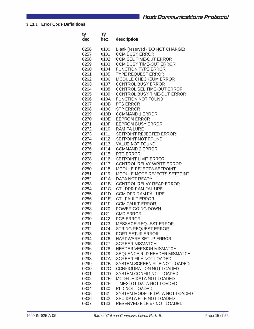
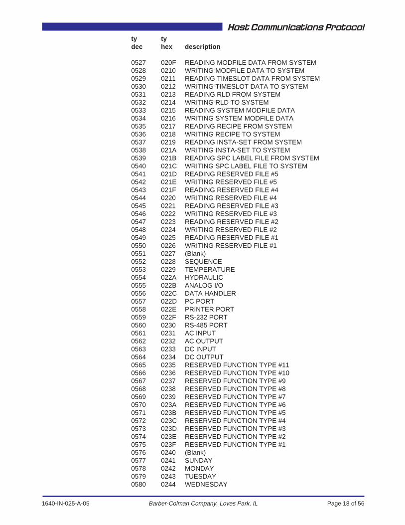
3.13.1 Error Code Definitions
ty tydec hex description
0256 0100 Blank (reserved - DO NOT CHANGE)0257 0101 COM BUSY ERROR0258 0102 COM SEL TIME-OUT ERROR0259 0103 COM BUSY TIME-OUT ERROR0260 0104 FUNCTION TYPE ERROR0261 0105 TYPE REQUEST ERROR0262 0106 MODULE CHECKSUM ERROR0263 0107 CONTROL BUSY ERROR0264 0108 CONTROL SEL TIME-OUT ERROR0265 0109 CONTROL BUSY TIME-OUT ERROR0266 010A FUNCTION NOT FOUND0267 010B PTS ERROR0268 010C STP ERROR0269 010D COMMAND 1 ERROR0270 010E EEPROM ERROR0271 010F EEPROM BUSY ERROR0272 0110 RAM FAILURE0273 0111 SETPOINT REJECTED ERROR0274 0112 SETPOINT NOT FOUND0275 0113 VALUE NOT FOUND0276 0114 COMMAND 2 ERROR0277 0115 RTC ERROR0278 0116 SETPOINT LIMIT ERROR0279 0117 CONTROL RELAY WRITE ERROR0280 0118 MODULE REJECTS SETPOINT0281 0119 MODULE MODE REJECTS SETPOINT0282 011A DATA NOT READY0283 011B CONTROL RELAY READ ERROR0284 011C CTL DPR RAM FAILURE0285 011D COM DPR RAM FAILURE0286 011E CTL FAULT ERROR0287 011F COM FAULT ERROR0288 0120 POWER GOING DOWN0289 0121 CMD ERROR0290 0122 PCB ERROR0291 0123 MESSAGE REQUEST ERROR0292 0124 STRING REQUEST ERROR0293 0125 PORT SETUP ERROR0294 0126 HARDWARE SETUP ERROR0295 0127 SCREEN MISMATCH0296 0128 HEADER VERSION MISMATCH0297 0129 SEQUENCE RLD HEADER MISMATCH0298 012A SCREEN FILE NOT LOADED0299 012B SYSTEM SCREEN FILE NOT LOADED0300 012C CONFIGURATION NOT LOADED0301 012D SYSTEM CONFIG NOT LOADED0302 012E MODFILE DATA NOT LOADED0303 012F TIMESLOT DATA NOT LOADED0304 0130 RLD NOT LOADED0305 0131 SYSTEM MODFILE DATA NOT LOADED0306 0132 SPC DATA FILE NOT LOADED0307 0133 RESERVED FILE #7 NOT LOADED
1640-IN-025-A-05 Page 16 of 56
Host Communications Protocol
Barber-Colman Company, Loves Park, IL
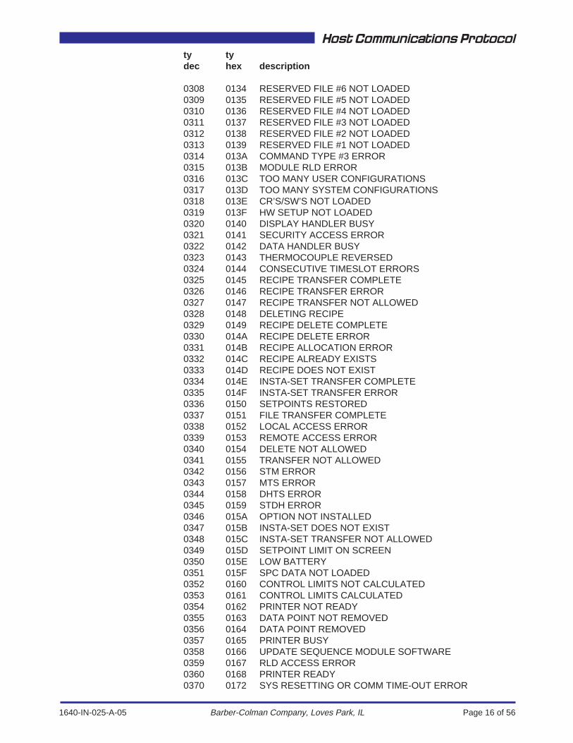
ty tydec hex description
0308 0134 RESERVED FILE #6 NOT LOADED0309 0135 RESERVED FILE #5 NOT LOADED0310 0136 RESERVED FILE #4 NOT LOADED0311 0137 RESERVED FILE #3 NOT LOADED0312 0138 RESERVED FILE #2 NOT LOADED0313 0139 RESERVED FILE #1 NOT LOADED0314 013A COMMAND TYPE #3 ERROR0315 013B MODULE RLD ERROR0316 013C TOO MANY USER CONFIGURATIONS0317 013D TOO MANY SYSTEM CONFIGURATIONS0318 013E CR’S/SW’S NOT LOADED0319 013F HW SETUP NOT LOADED0320 0140 DISPLAY HANDLER BUSY0321 0141 SECURITY ACCESS ERROR0322 0142 DATA HANDLER BUSY0323 0143 THERMOCOUPLE REVERSED0324 0144 CONSECUTIVE TIMESLOT ERRORS0325 0145 RECIPE TRANSFER COMPLETE0326 0146 RECIPE TRANSFER ERROR0327 0147 RECIPE TRANSFER NOT ALLOWED0328 0148 DELETING RECIPE0329 0149 RECIPE DELETE COMPLETE0330 014A RECIPE DELETE ERROR0331 014B RECIPE ALLOCATION ERROR0332 014C RECIPE ALREADY EXISTS0333 014D RECIPE DOES NOT EXIST0334 014E INSTA-SET TRANSFER COMPLETE0335 014F INSTA-SET TRANSFER ERROR0336 0150 SETPOINTS RESTORED0337 0151 FILE TRANSFER COMPLETE0338 0152 LOCAL ACCESS ERROR0339 0153 REMOTE ACCESS ERROR0340 0154 DELETE NOT ALLOWED0341 0155 TRANSFER NOT ALLOWED0342 0156 STM ERROR0343 0157 MTS ERROR0344 0158 DHTS ERROR0345 0159 STDH ERROR0346 015A OPTION NOT INSTALLED0347 015B INSTA-SET DOES NOT EXIST0348 015C INSTA-SET TRANSFER NOT ALLOWED0349 015D SETPOINT LIMIT ON SCREEN0350 015E LOW BATTERY0351 015F SPC DATA NOT LOADED0352 0160 CONTROL LIMITS NOT CALCULATED0353 0161 CONTROL LIMITS CALCULATED0354 0162 PRINTER NOT READY0355 0163 DATA POINT NOT REMOVED0356 0164 DATA POINT REMOVED0357 0165 PRINTER BUSY0358 0166 UPDATE SEQUENCE MODULE SOFTWARE0359 0167 RLD ACCESS ERROR0360 0168 PRINTER READY0370 0172 SYS RESETTING OR COMM TIME-OUT ERROR
1640-IN-025-A-05 Page 17 of 56
Host Communications Protocol
Barber-Colman Company, Loves Park, IL
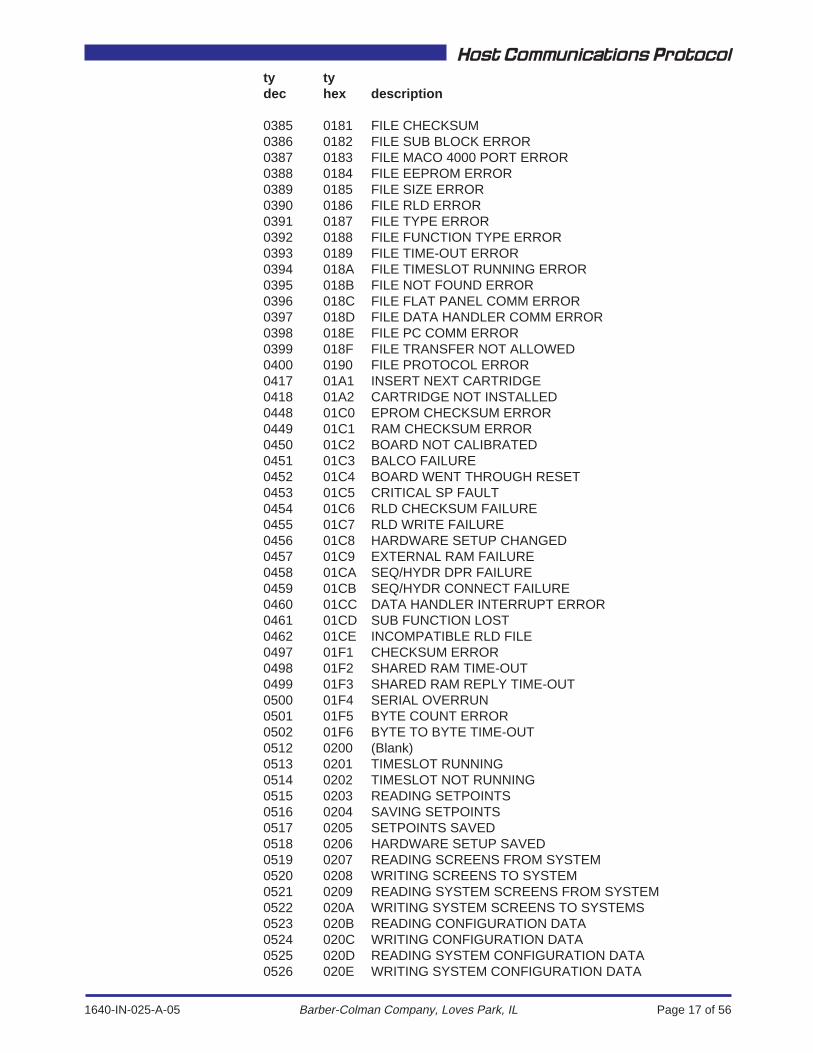
ty tydec hex description
0385 0181 FILE CHECKSUM0386 0182 FILE SUB BLOCK ERROR0387 0183 FILE MACO 4000 PORT ERROR0388 0184 FILE EEPROM ERROR0389 0185 FILE SIZE ERROR0390 0186 FILE RLD ERROR0391 0187 FILE TYPE ERROR0392 0188 FILE FUNCTION TYPE ERROR0393 0189 FILE TIME-OUT ERROR0394 018A FILE TIMESLOT RUNNING ERROR0395 018B FILE NOT FOUND ERROR0396 018C FILE FLAT PANEL COMM ERROR0397 018D FILE DATA HANDLER COMM ERROR0398 018E FILE PC COMM ERROR0399 018F FILE TRANSFER NOT ALLOWED0400 0190 FILE PROTOCOL ERROR0417 01A1 INSERT NEXT CARTRIDGE0418 01A2 CARTRIDGE NOT INSTALLED0448 01C0 EPROM CHECKSUM ERROR0449 01C1 RAM CHECKSUM ERROR0450 01C2 BOARD NOT CALIBRATED0451 01C3 BALCO FAILURE0452 01C4 BOARD WENT THROUGH RESET0453 01C5 CRITICAL SP FAULT0454 01C6 RLD CHECKSUM FAILURE0455 01C7 RLD WRITE FAILURE0456 01C8 HARDWARE SETUP CHANGED0457 01C9 EXTERNAL RAM FAILURE0458 01CA SEQ/HYDR DPR FAILURE0459 01CB SEQ/HYDR CONNECT FAILURE0460 01CC DATA HANDLER INTERRUPT ERROR0461 01CD SUB FUNCTION LOST0462 01CE INCOMPATIBLE RLD FILE0497 01F1 CHECKSUM ERROR0498 01F2 SHARED RAM TIME-OUT0499 01F3 SHARED RAM REPLY TIME-OUT0500 01F4 SERIAL OVERRUN0501 01F5 BYTE COUNT ERROR0502 01F6 BYTE TO BYTE TIME-OUT0512 0200 (Blank)0513 0201 TIMESLOT RUNNING0514 0202 TIMESLOT NOT RUNNING0515 0203 READING SETPOINTS0516 0204 SAVING SETPOINTS0517 0205 SETPOINTS SAVED0518 0206 HARDWARE SETUP SAVED0519 0207 READING SCREENS FROM SYSTEM0520 0208 WRITING SCREENS TO SYSTEM0521 0209 READING SYSTEM SCREENS FROM SYSTEM0522 020A WRITING SYSTEM SCREENS TO SYSTEMS0523 020B READING CONFIGURATION DATA0524 020C WRITING CONFIGURATION DATA0525 020D READING SYSTEM CONFIGURATION DATA0526 020E WRITING SYSTEM CONFIGURATION DATA
1640-IN-025-A-05 Page 18 of 56
Host Communications Protocol
Barber-Colman Company, Loves Park, IL
ty tydec hex description
0527 020F READING MODFILE DATA FROM SYSTEM0528 0210 WRITING MODFILE DATA TO SYSTEM0529 0211 READING TIMESLOT DATA FROM SYSTEM0530 0212 WRITING TIMESLOT DATA TO SYSTEM0531 0213 READING RLD FROM SYSTEM0532 0214 WRITING RLD TO SYSTEM0533 0215 READING SYSTEM MODFILE DATA0534 0216 WRITING SYSTEM MODFILE DATA0535 0217 READING RECIPE FROM SYSTEM0536 0218 WRITING RECIPE TO SYSTEM0537 0219 READING INSTA-SET FROM SYSTEM0538 021A WRITING INSTA-SET TO SYSTEM0539 021B READING SPC LABEL FILE FROM SYSTEM0540 021C WRITING SPC LABEL FILE TO SYSTEM0541 021D READING RESERVED FILE #50542 021E WRITING RESERVED FILE #50543 021F READING RESERVED FILE #40544 0220 WRITING RESERVED FILE #40545 0221 READING RESERVED FILE #30546 0222 WRITING RESERVED FILE #30547 0223 READING RESERVED FILE #20548 0224 WRITING RESERVED FILE #20549 0225 READING RESERVED FILE #10550 0226 WRITING RESERVED FILE #10551 0227 (Blank)0552 0228 SEQUENCE0553 0229 TEMPERATURE0554 022A HYDRAULIC0555 022B ANALOG I/O0556 022C DATA HANDLER0557 022D PC PORT0558 022E PRINTER PORT0559 022F RS-232 PORT0560 0230 RS-485 PORT0561 0231 AC INPUT0562 0232 AC OUTPUT0563 0233 DC INPUT0564 0234 DC OUTPUT0565 0235 RESERVED FUNCTION TYPE #110566 0236 RESERVED FUNCTION TYPE #100567 0237 RESERVED FUNCTION TYPE #90568 0238 RESERVED FUNCTION TYPE #80569 0239 RESERVED FUNCTION TYPE #70570 023A RESERVED FUNCTION TYPE #60571 023B RESERVED FUNCTION TYPE #50572 023C RESERVED FUNCTION TYPE #40573 023D RESERVED FUNCTION TYPE #30574 023E RESERVED FUNCTION TYPE #20575 023F RESERVED FUNCTION TYPE #10576 0240 (Blank)0577 0241 SUNDAY0578 0242 MONDAY0579 0243 TUESDAY0580 0244 WEDNESDAY

1640-IN-025-A-05 Page 19 of 56
Host Communications Protocol
Barber-Colman Company, Loves Park, IL
ty tydec hex description
0581 0245 THURSDAY0582 0246 FRIDAY0583 0247 SATURDAY0584 0248 WEEKDAY0585 0249 WEEKEND0586 024A JANUARY0587 024B FEBRUARY0588 024C MARCH0589 024D APRIL0590 024E MAY0591 024F JUNE0592 0250 JULY0593 0251 AUGUST0594 0252 SEPTEMBER0595 0253 OCTOBER0596 0254 NOVEMBER0597 0255 DECEMBER0598 0256 DISABLED0599 0257 SECONDS0600 0258 MINUTES0601 0259 HOURS0602 025A DAYS0603 025B Disabled0604 025C Ram Vel SP0605 025D Ram PR SP0606 025E Ram PR0607 025F Clamp PR0608 0260 Ram Vel0609 0261 Ram Pos0610 0262 Clamp Pos0611 0263 Ejector Pos0612 0264 Tach RPM0613 0265 PID Output0614 0266 Analog Out 10615 0267 Analog Out 20616 0268 Analog Out 30617 0269 Analog Out 40618 026A Screw Out0622 026E (Blank)0623 026F ips0624 0270 psi0625 0271 psi0626 0272 psi0627 0273 ips0628 0274 in0629 0275 in0630 0276 in0631 0277 rpm0632 0278 %0633 0279 (Blank)0634 027A (Blank)0635 027B (Blank)0636 027C (Blank)0637 027D %

1640-IN-025-A-05 Page 20 of 56
Host Communications Protocol
Barber-Colman Company, Loves Park, IL
ty tydec hex description
0641 0281 (Blank)0642 0282 Printer0643 0283 Reserved 20644 0284 System Modfile0645 0285 RLD0646 0286 System Screen0647 0287 User Screen0648 0288 User Config0649 0289 Recipe0650 028A Reserved 90651 028B User SPC Labels0652 028C Timeslot data0653 028D User Modfile0654 028E Reserved 130655 028F Reserved 140656 0290 System Config0657 0291 Reserved 160658 0292 Reserved 170659 0293 Reserved 180660 0294 Reserved 190661 0295 Insta-set0662 0296 Reserved 210663 0297 Reserved 220664 0298 Reserved 230665 0299 Reserved 240666 029A Reserved 250667 029B WRITING SCREENS TO CARTRIDGE0668 029C WRITING SYSTEM SCREENS TO CARTRIDGE0669 029D WRITING CONFIGURATION TO CARTRIDGE0670 029E WRITING SYS. CONFIG. TO CARTRIDGE0671 029F WRITING MODFILE DATA TO CARTRIDGE0672 02A0 WRITING TIMESLOT DATA TO CARTRIDGE0673 02A1 WRITING RLD TO CARTRIDGE0674 02A2 WRITE SYS. MODFILE DATA TO CARTRIDGE0675 02A3 WRITING RECIPE TO CARTRIDGE0676 02A4 WRITING INSTA-SET TO CARTRIDGE0677 02A5 WRITING SPC LABEL FILE TO CARTRIDGE0678 02A6 WRITING RESERVED FILE #5 TO CARTRIDGE0679 02A7 WRITING RESERVED FILE #4 TO CARTRIDGE0680 02A8 WRITING RESERVED FILE #3 TO CARTRIDGE0681 02A9 WRITING RESERVED FILE #2 TO CARTRIDGE0682 02AA WRITING RESERVED FILE #1 TO CARTRIDGE

1640-IN-025-A-05 Page 21 of 56
Host Communications Protocol
Barber-Colman Company, Loves Park, IL
3.16 Example, Request Data, Counter 1 Value (Sequence)
HOST COMPUTER BYTECOUNT
07H
STATUSBYTE00H
PRIMARYCONTROL
BYTE45H
FUNCTIONADDRESS
11HCHECKSUM
8AH
TOTAL1's COMPLEMENT2's COMPLEMENT = 8AH
MACO UNIT
ID01H
BYTECOUNT05H
STATUSBYTE00H
(LSB)DATA
114H
(MSB)DATA
279H
CHECKSUM2AH
TOTAL1's COMPLEMENT2's COMPLEMENT = 2AH
0001 10000000 00000000 00010001 00010100 01010000 00000000 0111 0111 01101000 10011000 1010
0111 10010001 01000100 00110000 00000000 01010000 00011101 01100010 10010010 1010
FUNCTIONNUMBER
01H
TYPE,UPPER00H
TYPE,LOWER18H
PRIMARYCONTROL
BYTE43H
3.15 Primary Control Byte Definition
B B B B B B B B7 6 5 4 3 2 1 0
CONTROL TYPE01
= Data= Error
WRITE or READ
01
= Write (changing something)= Read (looking at something)
PRIMARY CONTROL BLOCK BYTE COUNT1 - 63 is validDoes NOT include:
Unit IDByte CountStatus ByteChecksum ByteAny Secondary Control/Data Bytes
<UID><BC><SB><CK>
<DLE><DLE>
3.14 Status Byte Definition
B B B B B B B B7 6 5 4 3 2 1 0
RESERVED RESERVED
CR CHANGE FLAG0 = No Change1 = Change
NOTE: The status byte is not used much in RS-232 host �communications. The byte contains a CR change flagwhich is monitored by the display and indicates a change in one of the control relays with System Adressess1977-2040 (Sequence Module).
Once the display examines the flag bit, the bit is cleared.Depending on when the status byte is examined, hostcommunications may or may not be able to determine a change has occurred.
1640-IN-025-A-05 Page 22 of 56
Host Communications Protocol
Barber-Colman Company, Loves Park, IL
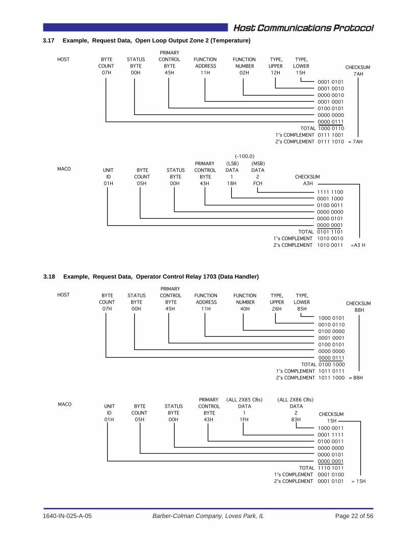
3.17 Example, Request Data, Open Loop Output Zone 2 (Temperature)
HOST BYTECOUNT
07H
STATUSBYTE00H
PRIMARYCONTROL
BYTE45H
FUNCTIONADDRESS
11HCHECKSUM
7AH
TOTAL1's COMPLEMENT2's COMPLEMENT = 7AH
MACO UNITID
01H
BYTECOUNT05H
STATUSBYTE00H
(LSB)DATA
118H
(MSB)DATA
2FCH
CHECKSUMA3H
TOTAL1's COMPLEMENT2's COMPLEMENT =A3 H
0001 01010001 00100000 00100001 00010100 01010000 00000000 0111 1000 01100111 10010111 1010
1111 11000001 10000100 00110000 00000000 01010000 00010101 11011010 00101010 0011
FUNCTIONNUMBER
02H
TYPE,UPPER12H
TYPE,LOWER15H
(-100.0)
3.18 Example, Request Data, Operator Control Relay 1703 (Data Handler)
HOST BYTECOUNT
07H
STATUSBYTE00H
PRIMARYCONTROL
BYTE45H
FUNCTIONADDRESS
11HCHECKSUM
B8H
TOTAL1's COMPLEMENT2's COMPLEMENT = B8H
MACO UNITID
01H
BYTECOUNT
05H
STATUSBYTE00H
DATA1
1FH
DATA2
83HCHECKSUM
15H
TOTAL1's COMPLEMENT2's COMPLEMENT = 15H
1000 01010010 01100100 00000001 00010100 01010000 00000000 0111 0100 10001011 01111011 1000
1000 00110001 11110100 00110000 00000000 01010000 00011110 10110001 01000001 0101
FUNCTIONNUMBER
40H
TYPE,UPPER26H
TYPE,LOWER
85H
(ALL 2X85 CRs) (ALL 2X86 CRs)
PRIMARYCONTROL
BYTE43H
PRIMARYCONTROL
BYTE43H
1640-IN-025-A-05 Page 23 of 56
Host Communications Protocol
Barber-Colman Company, Loves Park, IL
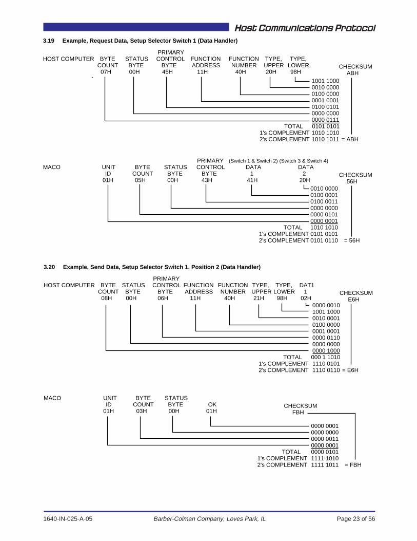
3.19 Example, Request Data, Setup Selector Switch 1 (Data Handler)
HOST COMPUTER BYTECOUNT07H
STATUSBYTE00H
PRIMARYCONTROL
BYTE45H
FUNCTIONADDRESS
11HCHECKSUM
ABH
TOTAL1's COMPLEMENT2's COMPLEMENT = ABH
MACO UNITID
01H
BYTECOUNT05H
STATUSBYTE00H
DATA1
41H
DATA2
20HCHECKSUM
56H
TOTAL1's COMPLEMENT2's COMPLEMENT = 56H
1001 1000 0010 00000100 00000001 00010100 01010000 00000000 0111 0101 01011010 10101010 1011
0010 00000100 00010100 00110000 00000000 01010000 00011010 10100101 01010101 0110
FUNCTIONNUMBER
40H
TYPE,UPPER20H
TYPE,LOWER98H
3.20 Example, Send Data, Setup Selector Switch 1, Position 2 (Data Handler)
HOST COMPUTER BYTECOUNT08H
STATUSBYTE00H
PRIMARYCONTROL
BYTE06H
FUNCTIONADDRESS
11HCHECKSUM
E6H
TOTAL1's COMPLEMENT2's COMPLEMENT = E6H
MACO UNITID
01H
BYTECOUNT03H
STATUSBYTE00H
OK01H
CHECKSUMFBH
TOTAL1's COMPLEMENT2's COMPLEMENT = FBH
0000 00101001 10000010 00010100 00000001 00010000 01100000 00000000 1000000 1 10101110 01011110 0110
0000 00010000 00000000 00110000 00010000 01011111 10101111 1011
FUNCTIONNUMBER
40H
TYPE,UPPER21H
TYPE,LOWER98H
(Switch 1 & Switch 2) (Switch 3 & Switch 4)
DAT11
02H
PRIMARYCONTROL
BYTE43H
1640-IN-025-A-05 Page 24 of 56
Host Communications Protocol
Barber-Colman Company, Loves Park, IL
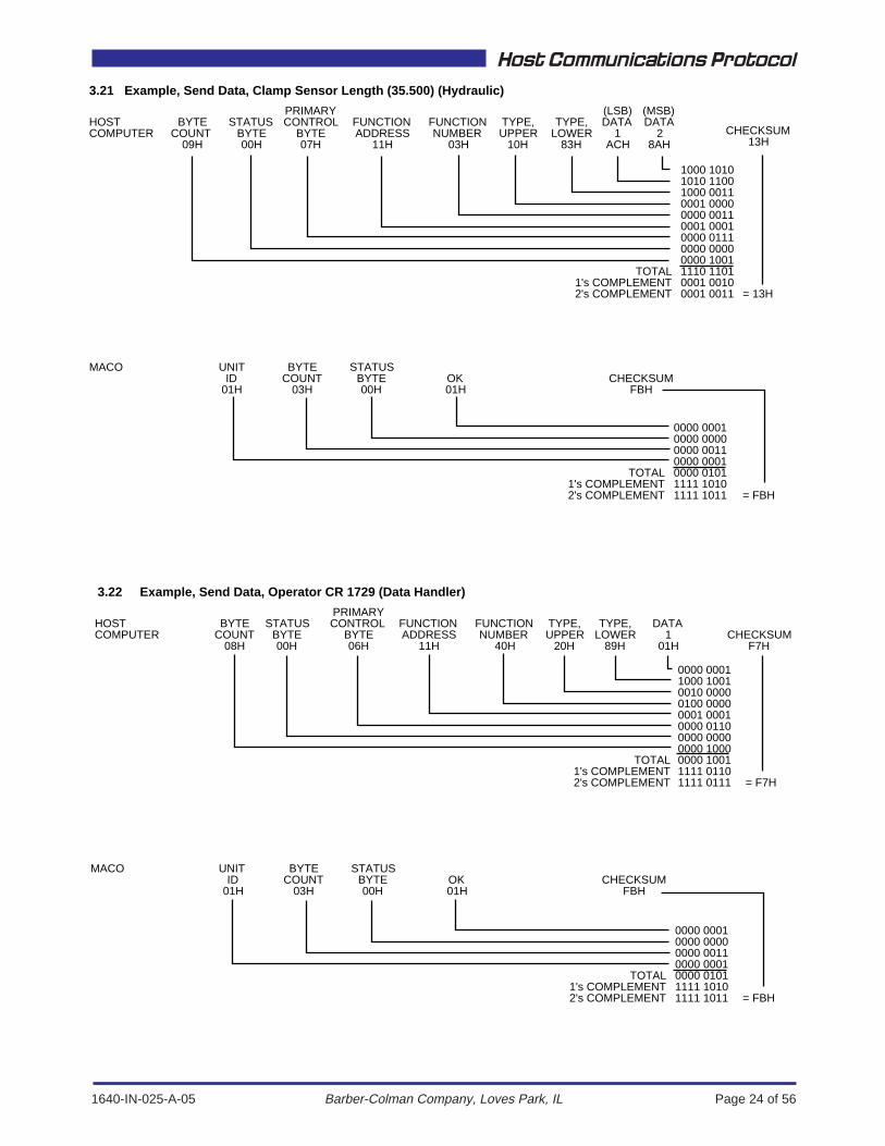
3.21 Example, Send Data, Clamp Sensor Length (35.500) (Hydraulic)
3.22 Example, Send Data, Operator CR 1729 (Data Handler)
HOSTCOMPUTER
BYTECOUNT
08H
STATUSBYTE00H
PRIMARYCONTROL
BYTE06H
FUNCTIONADDRESS
11HCHECKSUM
F7H
TOTAL1's COMPLEMENT2's COMPLEMENT = F7H
MACO UNITID
01H
BYTECOUNT
03H
STATUSBYTE00H
OK01H
CHECKSUMFBH
TOTAL1's COMPLEMENT2's COMPLEMENT = FBH
0000 00011000 10010010 00000100 00000001 00010000 01100000 00000000 10000000 10011111 01101111 0111
0000 00010000 00000000 00110000 00010000 01011111 10101111 1011
FUNCTIONNUMBER
40H
TYPE,UPPER
20H
TYPE,LOWER
89H
DATA1
01H
HOSTCOMPUTER
BYTECOUNT
09H
STATUSBYTE00H
PRIMARYCONTROL
BYTE07H
FUNCTIONADDRESS
11HCHECKSUM
13H
TOTAL1's COMPLEMENT2's COMPLEMENT = 13H
MACO UNITID
01H
BYTECOUNT
03H
STATUSBYTE00H
OK01H
CHECKSUMFBH
TOTAL1's COMPLEMENT2's COMPLEMENT = FBH
1000 10101010 11001000 00110001 00000000 00110001 00010000 01110000 00000000 10011110 11010001 00100001 0011
0000 00010000 00000000 00110000 00010000 01011111 10101111 1011
FUNCTIONNUMBER
03H
TYPE,UPPER
10H
TYPE,LOWER
83H
(LSB)DATA
1ACH
(MSB)DATA
28AH

1640-IN-025-A-05 Page 25 of 56
Host Communications Protocol
Barber-Colman Company, Loves Park, IL
4. RS-485 Host CommunicationsThe MACO RS-485 Host communications module provides the capability to linkyour MACO 4000, 5000 and 6000 series control systems to a host computer. Thisallows full Supervisory Control and Data Acquisition (SCADA) over a standardnetwork platform. A single serial port on a computer can communicate with up to32 MACO controlled machines on a single cable. The host computer can collect,display and store operating data, as well as transmit setpoints and change controlrelay states to the MACO controllers.
Data can be read or written to MACO in blocks or as individual values or setpoints.Up to ten blocks can be defined. Each block can have as many as 60 values and/or setpoints. The module scans the menu of data items requested by the hostcomputer, starting with block “0” and proceeds until it encounters a blank block.There can be no blank fields within a block so be sure to construct a contiguousmenu when setting up your data acquisition routine at the host computer.
The buffer holds up to five blocks of data. The BUFFER MODE setpointdetermines the number of blocks to be gathered on a zero to 1 transition of theTRIGGER CR. If the BUFFER MODE setpoint = 0, the module collects datacontinuously. If the BUFFER MODE setpoint = 1, 2, 3, 4 or 5, data collection startswhen the TRIGGER CR goes high. The trigger does not have to be held high forthe entire gathering cycle. The DATA VALID CR (3765) is set when the specifiednumber of blocks has been collected and transferred to the output buffer.(Additional blocks, if requested, are gathered continuously).
4.1 Hardware RequirementsThere are two hardware jumpers and a bank o f 8 switches that must be manuallyset before installing the RS-485 host communications module (daughterboard)onto the communications motherboard.
Jumpers J1 and J2 are used to terminate the RS-485 data lines of your network.If you have three machines equipped with MACO's, the node located farthest fromhost would have the jumpers in the "IN" position and the other nodes would havethe jumpers in the "OUT" position.
The first 6 (1 - 6) switches of S1 are used to establish a node address for the card.Switches 7 and 8 determine some data transfer parameters (see next page).
The RS-485 host communication module can be used with Data Handler V20.76or newer and Sequence V03.46 or newer.
4.1.1 Editor RequirementsThe following versions of screen and RLD editors are required:
OptiGrafix V3.04 or newerRLD V4.5 or newer
SHIELD
ISOCOM
DATA
DATA
4
3
2
1
ON OFF S1
87654321
IN OUT
J1
U10
RS-485 COMMUNICATIONS
T1
IN OUT
J2
Figure 4. RS-485 Host Communication Module

1640-IN-025-A-05 Page 26 of 56
Host Communications Protocol
Barber-Colman Company, Loves Park, IL
4.1.2 Switch Definitions
4.1.2.1 Switches 1 - 6 Node Address (UID)The MACO node address on the RS-485 network is set by using dip switch S1 onthe RS-485 host communication module. The module address is encoded inbinary as shown below.
Switches Setting 0=OFF 1=ON x = Don't Care
Switches1 2 3 4 5 6 7 8
Node1 0 1 1 1 1 1 x x2 1 0 1 1 1 1 x x3 0 0 1 1 1 1 x x4 1 1 0 1 1 1 x x5 0 1 0 1 1 1 x x6 1 0 0 1 1 1 x x7 0 0 0 1 1 1 x x8 1 1 1 0 1 1 x x9 0 1 1 0 1 1 x x10 1 0 1 0 1 1 x x11 0 0 1 0 1 1 x x12 1 1 0 0 1 1 x x13 0 1 0 0 1 1 x x14 1 0 0 0 1 1 x x15 0 0 0 0 1 1 x x16 1 1 1 1 0 1 x x17 0 1 1 1 0 1 x x18 1 0 1 1 0 1 x x19 0 0 1 1 0 1 x x20 1 1 0 1 0 1 x x21 0 1 0 1 0 1 x x22 1 0 0 1 0 1 x x23 0 0 0 1 0 1 x x24 1 1 1 0 0 1 x x25 0 1 1 0 0 1 x x26 1 0 1 0 0 1 x x27 0 0 1 0 0 1 x x28 1 1 0 0 0 1 x x29 0 1 0 0 0 1 x x30 1 0 0 0 0 1 x x31 0 0 0 0 0 1 x x32 1 1 1 1 1 0 x x
Note: If all the switches (1-6) are in the ON position or a node address is greaterthan 32, the host communications module address will default to "0" and commu-nications will be disabled.
4.1.2.2 Switch 7 Save ConfigurationSwitch 7 ON: With switch 7 in the "ON" position, the table of parameters is savedin EEROM (on the RS-485 card). If the controller resets or powers down/powersup, the table will be read from the RS-485 card and does not need to be resent fromthe computer.
Switch 7 OFF: With switch 7 in the "OFF" position, the table of parameters is not
1640-IN-025-A-05 Page 27 of 56
Host Communications Protocol
Barber-Colman Company, Loves Park, IL
saved on the RS-485 card. If the controller resets or powers down/ powers up, thetable will have to be resent from the host.
4.1.2.3 Switch 8 Data UpdateWhen new data blocks are loaded, all setpoints and then all values are updatedduring the first pass through the new data. A block of data will not be sent to thehost until all setpoints and values have been updated (an error code of <NAK><46H>is sent until the data is ready).
Switch 8 ON: With switch 8 in the "ON" position, after the first update, values andsetpoints are updated at a ratio of 8 to 1 (values to setpoints, respectively).
Switch 8 OFF: With switch 8 in the "OFF" position, all setpoints and then all valuesare continuously updated.
4.1.3 Communication Board LocationThe RS-485 host communications module (daughterboard) mounts into anyposition on the communications motherboard.
The communications motherboard must be installed in a slot which has a controldata bus connector (the middle connector on the back-plane of the MACO controller.
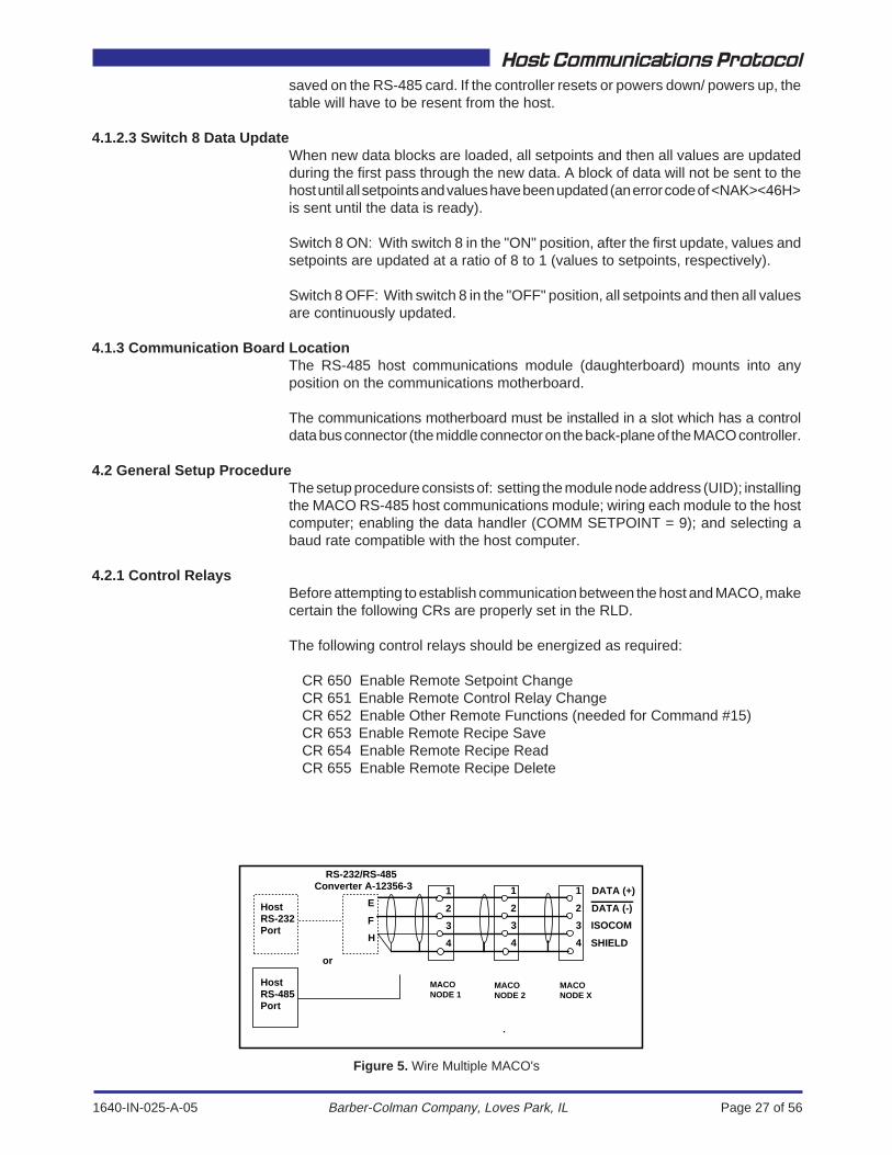
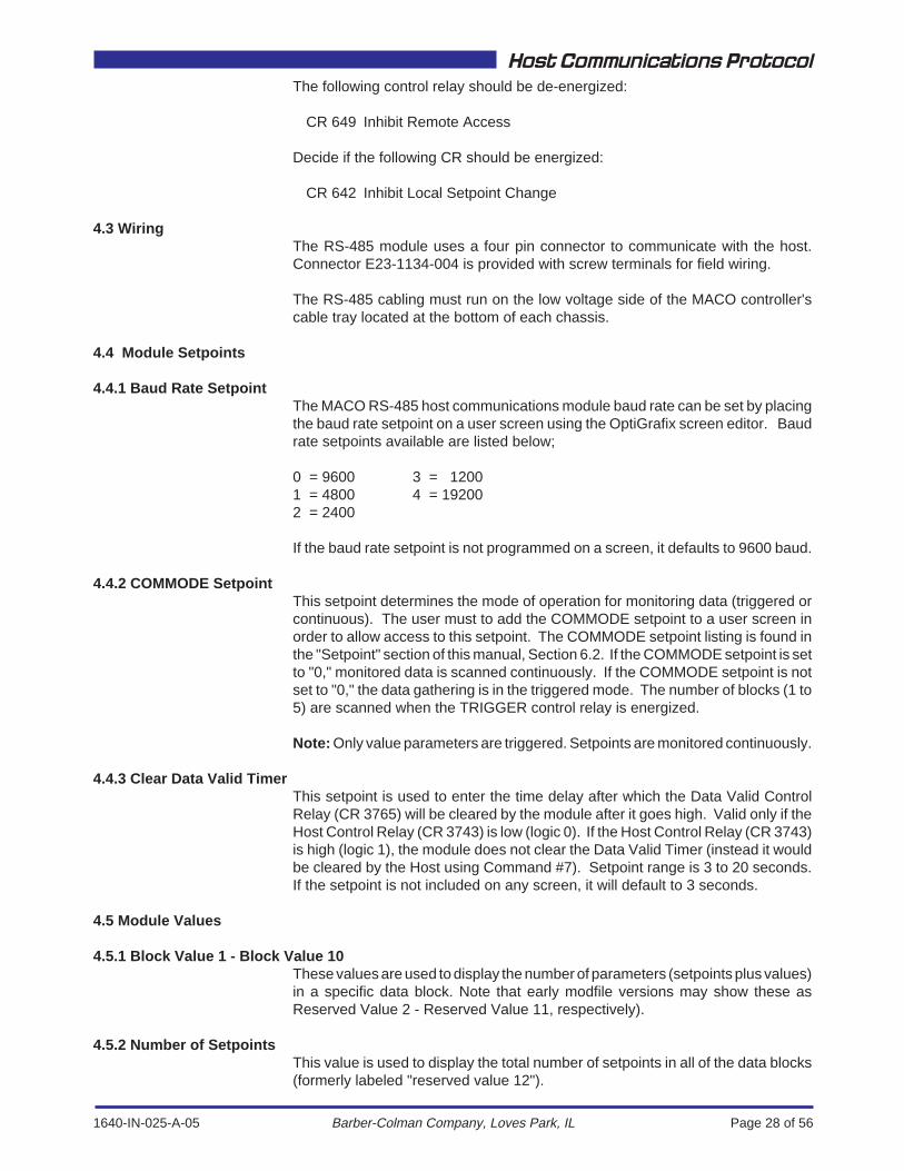
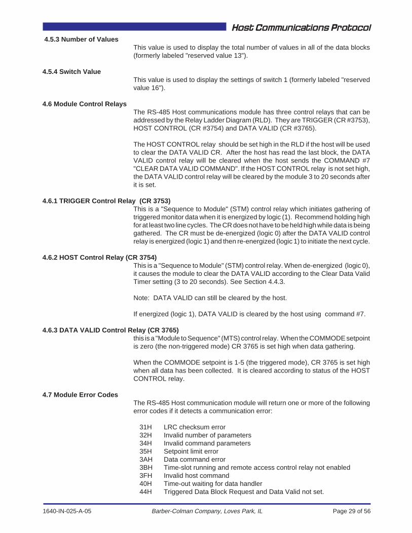
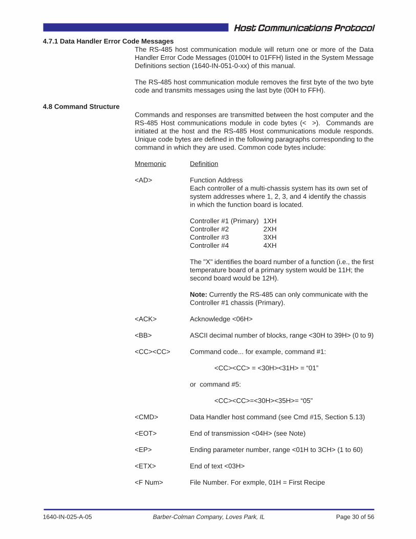
4.2 General Setup ProcedureThe setup procedure consists of: setting the module node address (UID); installingthe MACO RS-485 host communications module; wiring each module to the hostcomputer; enabling the data handler (COMM SETPOINT = 9); and selecting abaud rate compatible with the host computer.
4.2.1 Control RelaysBefore attempting to establish communication between the host and MACO, makecertain the following CRs are properly set in the RLD.
The following control relays should be energized as required:
CR 650 Enable Remote Setpoint ChangeCR 651 Enable Remote Control Relay ChangeCR 652 Enable Other Remote Functions (needed for Command #15)CR 653 Enable Remote Recipe SaveCR 654 Enable Remote Recipe ReadCR 655 Enable Remote Recipe Delete
SHIELD
ISOCOM
DATA (-)
DATA (+)
4
3
2
1
4
3
2
1
4
3
2
1
RS-232/RS-485Converter A-12356-3
HostRS-485Port
HostRS-232Port
or
MACONODE 1
MACONODE X
MACONODE 2
H
F
E
Figure 5. Wire Multiple MACO's
1640-IN-025-A-05 Page 28 of 56
Host Communications Protocol
Barber-Colman Company, Loves Park, IL
The following control relay should be de-energized:
CR 649 Inhibit Remote Access
Decide if the following CR should be energized:
CR 642 Inhibit Local Setpoint Change
4.3 WiringThe RS-485 module uses a four pin connector to communicate with the host.Connector E23-1134-004 is provided with screw terminals for field wiring.
The RS-485 cabling must run on the low voltage side of the MACO controller'scable tray located at the bottom of each chassis.
4.4 Module Setpoints
4.4.1 Baud Rate SetpointThe MACO RS-485 host communications module baud rate can be set by placingthe baud rate setpoint on a user screen using the OptiGrafix screen editor. Baudrate setpoints available are listed below;
0 = 9600 3 = 12001 = 4800 4 = 192002 = 2400
If the baud rate setpoint is not programmed on a screen, it defaults to 9600 baud.
4.4.2 COMMODE SetpointThis setpoint determines the mode of operation for monitoring data (triggered orcontinuous). The user must to add the COMMODE setpoint to a user screen inorder to allow access to this setpoint. The COMMODE setpoint listing is found inthe "Setpoint" section of this manual, Section 6.2. If the COMMODE setpoint is setto "0," monitored data is scanned continuously. If the COMMODE setpoint is notset to "0," the data gathering is in the triggered mode. The number of blocks (1 to5) are scanned when the TRIGGER control relay is energized.
Note: Only value parameters are triggered. Setpoints are monitored continuously.
4.4.3 Clear Data Valid TimerThis setpoint is used to enter the time delay after which the Data Valid ControlRelay (CR 3765) will be cleared by the module after it goes high. Valid only if theHost Control Relay (CR 3743) is low (logic 0). If the Host Control Relay (CR 3743)is high (logic 1), the module does not clear the Data Valid Timer (instead it wouldbe cleared by the Host using Command #7). Setpoint range is 3 to 20 seconds.If the setpoint is not included on any screen, it will default to 3 seconds.
4.5 Module Values
4.5.1 Block Value 1 - Block Value 10These values are used to display the number of parameters (setpoints plus values)in a specific data block. Note that early modfile versions may show these asReserved Value 2 - Reserved Value 11, respectively).
4.5.2 Number of SetpointsThis value is used to display the total number of setpoints in all of the data blocks(formerly labeled "reserved value 12").
1640-IN-025-A-05 Page 29 of 56
Host Communications Protocol
Barber-Colman Company, Loves Park, IL
4.5.3 Number of ValuesThis value is used to display the total number of values in all of the data blocks(formerly labeled "reserved value 13").
4.5.4 Switch ValueThis value is used to display the settings of switch 1 (formerly labeled "reservedvalue 16").
4.6 Module Control RelaysThe RS-485 Host communications module has three control relays that can beaddressed by the Relay Ladder Diagram (RLD). They are TRIGGER (CR #3753),HOST CONTROL (CR #3754) and DATA VALID (CR #3765).
The HOST CONTROL relay should be set high in the RLD if the host will be usedto clear the DATA VALID CR. After the host has read the last block, the DATAVALID control relay will be cleared when the host sends the COMMAND #7"CLEAR DATA VALID COMMAND". If the HOST CONTROL relay is not set high,the DATA VALID control relay will be cleared by the module 3 to 20 seconds afterit is set.
4.6.1 TRIGGER Control Relay (CR 3753)This is a "Sequence to Module" (STM) control relay which initiates gathering oftriggered monitor data when it is energized by logic (1). Recommend holding highfor at least two line cycles. The CR does not have to be held high while data is beinggathered. The CR must be de-energized (logic 0) after the DATA VALID controlrelay is energized (logic 1) and then re-energized (logic 1) to initiate the next cycle.
4.6.2 HOST Control Relay (CR 3754)This is a "Sequence to Module" (STM) control relay. When de-energized (logic 0),it causes the module to clear the DATA VALID according to the Clear Data ValidTimer setting (3 to 20 seconds). See Section 4.4.3.
Note: DATA VALID can still be cleared by the host.
If energized (logic 1), DATA VALID is cleared by the host using command #7.
4.6.3 DATA VALID Control Relay (CR 3765)this is a "Module to Sequence" (MTS) control relay. When the COMMODE setpointis zero (the non-triggered mode) CR 3765 is set high when data gathering.
When the COMMODE setpoint is 1-5 (the triggered mode), CR 3765 is set highwhen all data has been collected. It is cleared according to status of the HOSTCONTROL relay.
4.7 Module Error CodesThe RS-485 Host communication module will return one or more of the followingerror codes if it detects a communication error:
31H LRC checksum error32H Invalid number of parameters34H Invalid command parameters35H Setpoint limit error3AH Data command error3BH Time-slot running and remote access control relay not enabled3FH Invalid host command40H Time-out waiting for data handler44H Triggered Data Block Request and Data Valid not set.
1640-IN-025-A-05 Page 30 of 56
Host Communications Protocol
Barber-Colman Company, Loves Park, IL
4.7.1 Data Handler Error Code MessagesThe RS-485 host communication module will return one or more of the DataHandler Error Code Messages (0100H to 01FFH) listed in the System MessageDefinitions section (1640-IN-051-0-xx) of this manual.
The RS-485 host communication module removes the first byte of the two bytecode and transmits messages using the last byte (00H to FFH).
4.8 Command StructureCommands and responses are transmitted between the host computer and theRS-485 Host communications module in code bytes (< >). Commands areinitiated at the host and the RS-485 Host communications module responds.Unique code bytes are defined in the following paragraphs corresponding to thecommand in which they are used. Common code bytes include:
Mnemonic Definition
<AD> Function AddressEach controller of a multi-chassis system has its own set ofsystem addresses where 1, 2, 3, and 4 identify the chassisin which the function board is located.
Controller #1 (Primary) 1XHController #2 2XHController #3 3XHController #4 4XH
The "X" identifies the board number of a function (i.e., the firsttemperature board of a primary system would be 11H; thesecond board would be 12H).
Note: Currently the RS-485 can only communicate with theController #1 chassis (Primary).
<ACK> Acknowledge <06H>
<BB> ASCII decimal number of blocks, range <30H to 39H> (0 to 9)
<CC><CC> Command code... for example, command #1:
<CC><CC> = <30H><31H> = “01”
or command #5:
<CC><CC>=<30H><35H>= “05”
<CMD> Data Handler host command (see Cmd #15, Section 5.13)
<EOT> End of transmission <04H> (see Note)
<EP> Ending parameter number, range <01H to 3CH> (1 to 60)
<ETX> End of text <03H>
<F Num> File Number. For exmple, 01H = First Recipe

1640-IN-025-A-05 Page 31 of 56
Host Communications Protocol
Barber-Colman Company, Loves Park, IL
<FN> Function Number. MACO functions are identified as follows:
01H Sequence02H Temperature03H Hydraulic04H Parison05H Accel/Decel30H RS-232 Communications38H RS-485 SPI Communications3AH RS-485 Host Communications40H Data Handler
<FT> File Type (see Cmd #12, Section 5.10).
<LRC> Longitudinal redundancy check (Exclusive OR of all charactersin transmission except for the first <EOT>. Only the first <EOT>of a double <EOT><EOT> is included.
<LSB> Least significant byte. Example, CR 273E <LSB>=3E
<MF> Mode Function, (File/DH=C0H)
<MSB> Most significant byte. Example, CR 273E <MSB>=27
<NAK> Not acknowledged <15H>
<NN><NN> ASCII decimal character of number of parameters to be down-loaded. Example: 15 parameters <31H><35H>
<RCMD> Write code for operator control relays, setup control relays andselector switch control relays:
<RCMD>=0 Turn OFF control relay<RCMD>=1 Turn ON control relay<RCMD>=2 Toggle control relay
Selector Switches:
<RCMD>=0 OFF position<RCMD>=1 Position 1<RCMD>=2 Position 2<RCMD>=3 Position 3<RCMD>=4 Position 4
<Res> Reserved Byte (00H)
<SB> Sub-Block Number (always 0)
<SP> Starting parameter number, range <01H to 3CH> (1 to 60)
<STX> Start of Text <02H>
1640-IN-025-A-05 Page 32 of 56
Host Communications Protocol
Barber-Colman Company, Loves Park, IL
<TYU> Type, Upper - The Type Upper Byte distinguishes MACO typesas follows:
0XH is a Value1XH is a Setpoint2XH is a Control Relay4XH is an ASCII String5XH is a Module Alterable Setpoint6XH is a System Command
(Corresponds to the two left-most digits of parser entry. Thisentry is shown in both decimal and in hexadecimal (as used withhost communications). <TYU> and <TYL> form "ty."
<TYL> Type, Lower - The Type Lower Byte completes the identificationof specific Values, Setpoints, Control Relays or ASCII Strings(corresponds to the two right-most digits of parser entry). Thisentry is shown in decimal and in hexadecimal (as used withhost communications). <TYU> together with <TYL> form "ty."
<UID><UID> Node address of the MACO controlled machine. For example,machine #5:
<UID><UID> = <30H><35H> =“05”;
or machine #21:
<UID><UID> = <32H><31H> = “21”
Note: If data includes <EOT> (04H), then a second <EOT> (04H) should be sent,and only one <EOT> (04H) should be counted in the LRC.
If the LRC = <EOT> (04H), a backspace (08H) should be sent.
5. RS-485 Command CodesThe RS-485 Host communications module recognizes 13 commands from thehost computer:
Command Description1 Download menu parameters2 Request upload of block data3 Setpoint change (standard and module alterable)6 Request data valid status7 Clear data valid8 Individual setpoint/value request9 Control Relay Read10 Request ASCII String11 Change Operator Control Relay (Write)12 File Access - Read File13 File Access - Write File14 Request Host Monitor Error Table15 Data Handler Host Command
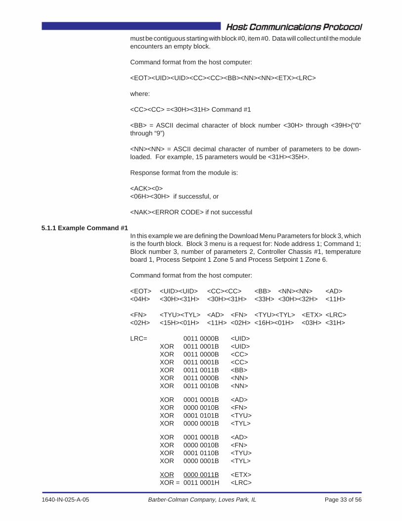
5.1 Command #1 — Download Menu ParametersThis command downloads up to ten menu blocks, each of which can contain 60setpoint and/or value definitions (AD, FN, TYU, TYL). A 3 to 5 second delay shouldbe allowed between blocks (depending on how the driver is written). The menu
1640-IN-025-A-05 Page 33 of 56
Host Communications Protocol
Barber-Colman Company, Loves Park, IL
must be contiguous starting with block #0, item #0. Data will collect until the moduleencounters an empty block.
Command format from the host computer:
<EOT><UID><UID><CC><CC><BB><NN><NN><ETX><LRC>
where:
<CC><CC> =<30H><31H> Command #1
<BB> = ASCII decimal character of block number <30H> through <39H>(“0”through “9”)
<NN><NN> = ASCII decimal character of number of parameters to be down-loaded. For example, 15 parameters would be <31H><35H>.
Response format from the module is:
<ACK><0><06H><30H> if successful, or
<NAK><ERROR CODE> if not successful
5.1.1 Example Command #1In this example we are defining the Download Menu Parameters for block 3, whichis the fourth block. Block 3 menu is a request for: Node address 1; Command 1;Block number 3, number of parameters 2, Controller Chassis #1, temperatureboard 1, Process Setpoint 1 Zone 5 and Process Setpoint 1 Zone 6.
Command format from the host computer:
<EOT> <UID><UID> <CC><CC> <BB> <NN><NN> <AD><04H> <30H><31H> <30H><31H> <33H> <30H><32H> <11H>
<FN> <TYU><TYL> <AD> <FN> <TYU><TYL> <ETX> <LRC><02H> <15H><01H> <11H> <02H> <16H><01H> <03H> <31H>
LRC= 0011 0000B <UID>XOR 0011 0001B <UID>XOR 0011 0000B <CC>XOR 0011 0001B <CC>XOR 0011 0011B <BB>XOR 0011 0000B <NN>XOR 0011 0010B <NN>
XOR 0001 0001B <AD>XOR 0000 0010B <FN>XOR 0001 0101B <TYU>XOR 0000 0001B <TYL>
XOR 0001 0001B <AD>XOR 0000 0010B <FN>XOR 0001 0110B <TYU>XOR 0000 0001B <TYL>
XOR 0000 0011B <ETX>XOR = 0011 0001H <LRC>
1640-IN-025-A-05 Page 34 of 56
Host Communications Protocol
Barber-Colman Company, Loves Park, IL
Response from the module:
<ACK> <0><06H> <30H>
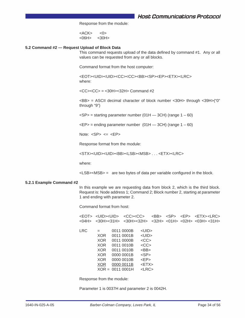
5.2 Command #2 — Request Upload of Block DataThis command requests upload of the data defined by command #1. Any or allvalues can be requested from any or all blocks.
Command format from the host computer:
<EOT><UID><UID><CC><CC><BB><SP><EP><ETX><LRC>where:
<CC><CC> = <30H><32H> Command #2
<BB> = ASCII decimal character of block number <30H> through <39H>(“0”through “9”)
<SP> = starting parameter number (01H — 3CH) (range 1 – 60)
<EP> = ending parameter number (01H — 3CH) (range 1 – 60)
Note: <SP> <= <EP>
Response format from the module:
<STX><UID><UID><BB><LSB><MSB> . . . <ETX><LRC>
where:
<LSB><MSB> = are two bytes of data per variable configured in the block.
5.2.1 Example Command #2In this example we are requesting data from block 2, which is the third block.Request is: Node address 1; Command 2; Block number 2, starting at parameter1 and ending with parameter 2.
Command format from host:
<EOT> <UID><UID> <CC><CC> <BB> <SP> <EP> <ETX> <LRC><04H> <30H><31H> <30H><32H> <32H> <01H> <02H> <03H> <31H>
LRC = 0011 0000B <UID>XOR 0011 0001B <UID>XOR 0011 0000B <CC>XOR 0011 0010B <CC>XOR 0011 0010B <BB>XOR 0000 0001B <SP>XOR 0000 0010B <EP>XOR 0000 0011B <ETX>XOR = 0011 0001H <LRC>
Response from the module:
Parameter 1 is 0037H and parameter 2 is 0042H.
1640-IN-025-A-05 Page 35 of 56
Host Communications Protocol
Barber-Colman Company, Loves Park, IL
<STX> <UID><UID> <BB> <LSB><MSB> <LSB><MSB> <ETX> <LRC><02H> <30H><31H> <32H> <37H><00H> <42H><00H> <03H> <47H>
LRC = 0000 0010B <STX>XOR 0011 0000B <UID>XOR 0011 0001B <UID>XOR 0011 0010B <BB>XOR 0011 0111B <LSB>XOR 0000 0000B <MSB>XOR 0100 0010B <LSB>XOR 0000 0000B <MSB>XOR 0000 0011B <ETX>XOR = 0100 0111B <LRC>
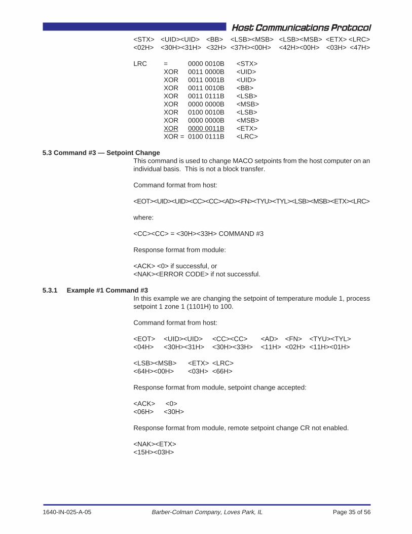
5.3 Command #3 — Setpoint ChangeThis command is used to change MACO setpoints from the host computer on anindividual basis. This is not a block transfer.
Command format from host:
<EOT><UID><UID><CC><CC><AD><FN><TYU><TYL><LSB><MSB><ETX><LRC>
where:
<CC><CC> = <30H><33H> COMMAND #3
Response format from module:
<ACK> <0> if successful, or<NAK><ERROR CODE> if not successful.
5.3.1 Example #1 Command #3In this example we are changing the setpoint of temperature module 1, processsetpoint 1 zone 1 (1101H) to 100.
Command format from host:
<EOT> <UID><UID> <CC><CC> <AD> <FN> <TYU><TYL><04H> <30H><31H> <30H><33H> <11H> <02H> <11H><01H>
<LSB><MSB> <ETX> <LRC><64H><00H> <03H> <66H>
Response format from module, setpoint change accepted:
<ACK> <0><06H> <30H>
Response format from module, remote setpoint change CR not enabled.
<NAK><ETX><15H><03H>
1640-IN-025-A-05 Page 36 of 56
Host Communications Protocol
Barber-Colman Company, Loves Park, IL
5.3.2 Example #2 Command #3In this example we are changing the setpoint of temperature module 1, processsetpoint 1 zone 1 (1101H) to 4.
Command format from host:
<EOT> <UID><UID> <CC><CC> <AD> <FN> <TYU><TYL><04H> <30H><31H> <30H><33H> <11H> <02H> <11H><01H>
<LSB><EOT><MSB> <ETX> <LRC><04H><04H><00H> <03H> <05H>
Because the setpoint is equal to 4 (an EOT), two 4's are transmitted. Responseformat from module, setpoint change accepted:
<ACK> <0><06H> <30H>
5.4 Command #6 – Request Data Valid StatusThis command requests the status of the DATA VALID control relay (CR 3765).The control relay is set to "1" when the data in the buffer is valid; and set to "0" whenit is not valid.
Command format from the host computer:
<EOT><UID><UID><CC><CC><ETX><LRC>
Response from Module:
<STX><UID><UID><BYTE 1><BYTE 2><BYTE 3><ETX> <LRC>if successful, else
<NAK><ERROR CODE> if not successful.
BYTE1 and BYTE 2 are dummy bytes and should be zero (0). Byte 3 contains allof the module's MTS control relays (8).
bit 0 CR3761 Reservedbit 1 CR3762 Reservedbit 2 CR3763 Reservedbit 3 CR3764 Reservedbit 4 CR3765 0=Data not ready; 1=Data Validbit 5 CR3766 Reservedbit 6 CR3767 Reservedbit 7 CR3768 Reserved
1640-IN-025-A-05 Page 37 of 56
Host Communications Protocol
Barber-Colman Company, Loves Park, IL
5.4.1 Example Command #6Request status of Data Valid CR 3765:
<EOT> <UID><UID> <CC><CC> <ETX> <LRC><04H> <30H><31H> <30H><36H> <03H> <08H>
LRC = 0011 0000B <UID>XOR 0011 0001B <UID>XOR 0011 0000B <CC>XOR 0011 0110B <CC>XOR 0000 0011B <ETX>XOR = 0000 0100B <LRC> = 0000 1000B <LRC>
Because the LRC is an EOT <04H>, change the LRC to a backspace (BS) <08H>.
Response from Module: If data valid not set.
<STX> <UID><UID> <BYTE 1> <BYTE 2> <BYTE 3><02H> <30H><31H> <00H> <00H> <00H>
<ETX> <LRC><03H> <0H>
The first two (2) data bytes are dummy bytes and will always be zero (0). Data validis bit 4 of the third data byte.
LRC = 0000 0010B <STX>XOR 0011 0000B <UID>XOR 0011 0001B <UID>XOR 0000 0000B <BYTE 1>XOR 0000 0000B <BYTE 2>XOR 0000 0000B <BYTE 3>XOR 0000 0011B <ETX>XOR =0000 0000B <LRC>
Response from Module: If data valid is set.
<STX> <UID><UID> <BYTE 1> <BYTE 2> <BYTE 3><02H> <30H><31H> <00H> <00H> <10H>
<ETX> <LRC><03H> <10H>
The first two (2) data bytes are dummy bytes and will always be zero (0).
LRC = 0000 0010B <STX>XOR 0011 0000B <UID>XOR 0011 0001B <UID>XOR 0000 0000B <BYTE 1>XOR 0000 0000B <BYTE 2>XOR 0001 0000B <BYTE 3>XOR 0000 0011B <ETX>XOR = 0001 0000B <LRC>
1640-IN-025-A-05 Page 38 of 56
Host Communications Protocol
Barber-Colman Company, Loves Park, IL
5.5 Command #7 – Clear DATA VALIDThis command clears the Data Valid control relay status flag after the host has readthe last block of data.
Command format from the host computer:
<EOT><UID><UID><CC><CC><ETX><LRC>
Response from Module:
<ACK><30H> if successful, or<NAK><ERROR CODE> if not successful.
5.5.1 Example Command 7
<EOT> <UID><UID> <CC><CC> <ETX> <LRC><04H> <30H><31H> <30H><37H> <03H> <05H>
LRC = 0011 0000B <UID>XOR 0011 0001B <UID>XOR 0011 0000B <CC>XOR 0011 0111B <CC>XOR 0000 0011B <ETX>XOR = 0000 0101B <LRC>
Response from the module:
<ACK> <3><06H> <30H>
5.6 Command #8 – Individual Setpoint/Value Request
This command requests an individual system setpoint or value.
Command format from the host computer:
<EOT><UID><UID><CC><CC><AD><FN><TYU><TYL> <ETX><LRC>
where: <CC><CC> = <30H><38H>
Response from the module:
<STX><UID><UID><LSB><MSB><ETX><LCR> if successful, or<NAK><ERROR CODE> if not successful.
5.6.1 Example Command #8Request timer setpoint 1 from module 1, rack 1.
Command format from the host computer:
<EOT> <UID><UID> <CC><CC> <AD> <FN> <TYU><TYL><04H> <30H><31H> <30H><38H> <11H> <01H> <10H><00H>
<ETX> <LRC><03H> <0AH>
1640-IN-025-A-05 Page 39 of 56
Host Communications Protocol
Barber-Colman Company, Loves Park, IL
LRC = 0011 0000B <UID>XOR 0011 0001B <UID>XOR 0011 0000B <CC>XOR 0011 1000B <CC>XOR 0001 0001B <AD>XOR 0000 0001B <FN>XOR 0001 0000B <TYU>XOR 0000 0000B <TYL>XOR 0000 0011B <ETX>XOR = 0000 1010B <LRC>
Response from the module:
The value for the requested setpoint is 0190H, 400.
<STX> <UID><UID> <LSB><MSB> <ETX> <LRC><02H> <30H><31H> <90H><01H> <03H> <91H>
LRC = 0000 0010B <STX>XOR 0011 0000B <UID>XOR 0011 0001B <UID>XOR 1001 0000B <LSB>XOR 0000 0001B <MSB>XOR 0000 0011B <ETX>XOR = 1001 0001B <LRC>
5.7 Command #9 – Control RelayThis command reads the status of any control relay (CR) with a system address.The following control relays may be read or written to:
Operator Control Relays, CR 1657 to 1752Off = logic 0, On = logic 1 and Toggle = logic 2
Setup Control Relays, CR 1785 to 1848Off = logic 0, On = logic 1 and Toggle = logic 2
Selector Switches , CR 1849 to 1912Off = logic 0, Position 1 = logic 1, Position 2 = logic 2Position 3 = logic 3, Position 4 = logic 4
Command format from the host computer:
<EOT><UID><UID><CC><CC><AD><FN><TYU><TYL> <ETX><LRC>
Response from Module:
<STX><UID><UID><BYTE 1><BYTE 2><ETX><LRC> if successful, or<NAK><ERROR CODE> if not successful.
1640-IN-025-A-05 Page 40 of 56
Host Communications Protocol
Barber-Colman Company, Loves Park, IL
5.7.1 Example Command #9In this example of control relay access, we are requesting the status sequenceInput 1 of sequence module 1 in chassis 1.
Command format from the host computer:
<EOT> <UID><UID> <CC><CC> <AD> <FN> <TYU><TYL><04H> <30H><31H> <30H><39H> <11H> <01H> <20H><00H>
<ETX> <LRC><03H> <3BH>
LRC = 0011 0000B <UID>XOR 0011 0001B <UID>XOR 0011 0000B <CC>XOR 0011 1001B <CC>XOR 0001 0001B <AD>XOR 0000 0001B <FN>XOR 0010 0000B <TYU>XOR 0000 0000B <TYL>XOR 0000 0011B <ETX>XOR = 0011 1011B <LRC>
Response from Module:
<STX> <UID><UID> <BYTE 1><BYTE 2> <ETX> <LRC><02H> <30H><31H> <00H><00H> <03H> <00H>
LRC = 0000 0010B <STX>XOR 0011 0000B <UID>XOR 0011 0001B <UID>XOR 0000 0000B <BYTE 1>XOR 0000 0000B <BYTE 2>XOR 0000 0011B <ETX>XOR = 0000 0000B <LRC>
5.8 Command #10 – Request ASCII StringThis command is used to request ASCII Strings, System Messages and SystemCommands. These strings are up to 29 characters in length.
Command format from the host computer:
<EOT><UID><UID><CC><CC><AD><FN><TYU><TYL> <ETX><LRC>
where: <CC> <CC> = <31>30><AD> = Function Address<FN> = Function Number
<TYU> = Type, Upper (3xH or 4xH)<TYL> = Type, Lower
If Type Upper = 4xH, the reply is a 29 character ASCII string. If the Type Upper =3xH, the reply is a sytem message number followed by 27 ASCII spaces. Thesystem messa number is converted within the Barber-Colman RS-485 DDEServer to return an ASCII string.
1640-IN-025-A-05 Page 41 of 56
Host Communications Protocol
Barber-Colman Company, Loves Park, IL
Response from Module:
<STX><UID><UID><BYTE 1><BYTE 2> .... <BYTE X> <ETX><LRC>if successful, or<NAK><ERROR CODE> if not successful.
Note that if the ASCII string is less than 29 characters it will be padded with ASCIIspaces (20H).
5.8.1 Example Command #10 – ASCII String Request (Type Upper = 4XH)
We are requesting the System Header File #3, System Modfile.
<EOT><30H><31H><31H><30H><11H><40H><45H><83H><ETX><94H>
LRC = XOR 0011 0000BXOR 0011 0001BXOR 0011 0001BXOR 0011 0000BXOR 0001 0001BXOR 0100 0000BXOR 0100 0101BXOR 1000 0011BXOR 0000 0011B (ETX)XOR = 1001 0100B (LRC = 94H)
VALID REPLY:The requested sac string reply is:
<STX><30H><31H><M><4><5><0><0>< ><S><T><A><N><D<A><R><D>< ><S><Y><S><T><E><M>< >< >< ><V><3><.><0>< ><ETX><29H>
NOTE: < > is an ASCII space (20H)
The requested ASCII string is: “M4500 STANDARD SYSTEM V3.0”LRC = 0000 0010B (STX)
XOR 0011 0000B (UID)XOR 0011 0001B (UID)XOR 0100 1101B (M)XOR 0011 0100B (4)XOR 0011 0101B (5)XOR 0011 0000B (0)XOR 0011 0000B (0)XOR 0010 0000B (SPACE)XOR 0101 0011B (S)XOR 0101 0100B (T)XOR 0100 0001B (A)XOR 0100 1110B (N)XOR 0100 0100B (D)XOR 0100 0001B (A)XOR 0101 0010B (R)XOR 0100 0100B (D)XOR 0010 0000B (SPACE)XOR 0101 0011B (S)XOR 0101 1001B (Y)XOR 0101 0011B (S)XOR 0101 0100B (T)

1640-IN-025-A-05 Page 42 of 56
Host Communications Protocol
Barber-Colman Company, Loves Park, IL
XOR 0100 0101B (E)XOR 0100 1101B (M)XOR 0010 0000B (SPACE)XOR 0010 0000B (SPACE)XOR 0010 0000B (SPACE)XOR 0101 0110B (V)XOR 0011 0011B (3)XOR 0010 1110B (.)XOR 0011 0000B (0)XOR 0010 0000B (SPACE)XOR 0000 0011B (ETX)XOR = 0010 1001B (LRC = 29H)
5.8.2 Example Command #10 – ASCII String Request (Type Upper = 3XH)
Request module displayable message for Module type 1 (module message3400H)
<EOT><30H><31H><31H><30H><11H><40H><34H><00H><ETX><0BH>
We are requesting the System Header File #3, System Modfile.
LRC = XOR 0011 0000B <ADDRESS, MSB>XOR 0011 0001B <ADDRESS, LSB>XOR 0011 0001B <COMMAND, MSB>XOR 0011 0000B <COMMAND, LSB>XOR 0001 0001B <Function Address>XOR 0100 0000B <Function number> ( 40H = Data Handler)XOR 0011 0100B <Type Upper, 3XH = Message No. request)XOR 0000 0000B <Type Lower, messageXOR 0000 0011B (ETX)XOR = 0110 0110B (LRC = 66H)
VALID REPLY:
<STX><30H><31H><29H><02H><20H>——<20H><ETX><0BH>NOTE: 27 bytes of ascii spaces (20H)
LRC = 0000 0010B (STX)XOR 0011 0000B module address (MSB)XOR 0011 0001B module address (LSB)XOR 0010 1001B setpoint LSBXOR 0000 0010B setpoint MSBXOR 0010 00000 twenty seven bytes of (20H) XOR’d = 20HXOR 0000 0011B (ETX)XOR = 0000 1011B (LRC = 0BH)
The message number = (2 * 256) + 41 = 553
The corresponding message in the message table is msg 553 = “TEMPERA-TURE”.
NOTE: IN SOME MESSAGE TABLES, THE FIRST MESSAGE IS LABELEDMESSAGE 1, THE FIRST MESSAGE IS ACTUALLY MESSAGE 0.
1640-IN-025-A-05 Page 43 of 56
Host Communications Protocol
Barber-Colman Company, Loves Park, IL
5.9 Command #11 – Change Control RelaysThis command is used to change the state of Operator Control Relays (CR 1657to 1752), Setup Control Relays (CR 1785 to 1848) and Selector Switches (CR1849 to 1912) from the host computer.
Command format from the host computer:
<EOT><UID><UID><CC><CC><AD><FN><TYU><TYL><RCMD><ETX><LRC>
Where <CC><CC> = <31H><31H> (11)<RCMD> = RELAY COMMAND
For operator control relays and setup control relays:
<RCMD> = 0 Turn OFF control relay<RCMD> = 1 Turn ON control relay<RCMD> = 2 Toggle control relay
For selector switch Control Relays:
<RCMD> = 0 OFF Position<RCMD> = 1 Position1<RCMD> = 2 Position2<RCMD> = 3 Position3<RCMD> = 4 Position4
Response from Module:
<ACK> < 0> no errors<06H> <30H>
<NAK><ERROR CODE> if not successful
5.9.1 Example Command #11This example changes Setup Control Relay #24 (CR 1808) to the ON state.
Command format from the host computer:
<EOT> <UID><UID> <CC><CC> <AD> <FN> <TYU> <TYL><04H> <30H><31H> <31H><31H> <11H> <40H> <27H> <92H>
<RCMD> <ETX> <LRC><01H> <03H> <E7H>
LRC = 0011 0000B <UID>XOR 0011 0001B <UID>XOR 0011 0001B <CC>XOR 0011 0001B <CC>XOR 0001 0001B <AD>XOR 0100 0000B <FN>XOR 0010 0111B <TYU>XOR 1001 0010B <TYL>XOR 0000 0001B <RCMD>XOR 0000 0011B <ETX>XOR = 1110 0111B <LRC>
1640-IN-025-A-05 Page 44 of 56
Host Communications Protocol
Barber-Colman Company, Loves Park, IL
Response from the module:
Valid Reply: Control Relay change accepted<ACK> < 0><06H> <30H>
Error Reply: Remote Control Relay change CR not enabled<NAK> <;><15H> <3BH>
5.10 Command #12 – File Access – Read FileThis command is used to request a file from the MACO.
Command format from the host computer:<EOT><UID><UID><CC><CC><AD><MF><Res><FT><BN_LSB><BN_MSB><SB><F Num><Res><Res><Res><ETX><LRC>
where:
<EOT> Start of transmission (04H)<UID><UID> Node address of MACO controlled machine<CC><CC> Command code<AD> Function Address<MF> Mode Function (File request for Data Handler = C0H)<Res> Reserved byte (00H)<FT> File type (for example 08H= Recipe file, see Table 1)<BN_LSB> Block number, LSB<BN_MSB> Block number, MSB<SB> Sub-Block number (always 0)<F Num> File number (for example, 01H=First recipe)<Res> Reserved byte (00H)<Res> Reserved byte (00H)<Res> Reserved byte (00H)<ETX> End of text (03H)<LRC> Longitudinal redundancy check
Response from the module:Each file block reply will be a 256 byte block consisting of a 16 byte header followedby 240 bytes of data, an <ETX> and an <LRC> for a total of 258 bytes.
The first block of each file (Block 0) contains only 96 bytes of data and is paddedwith nulls (00H) to make a full block of 256 bytes. The first 64 bytes are ASCIIcharacters and the next 32 bytes contain the file information, followed by 144 bytesof nulls (00H), then ETX and the LRC.

1640-IN-025-A-05 Page 45 of 56
Host Communications Protocol
Barber-Colman Company, Loves Park, IL
Table 1. File Types
FileType Description
FileExtension
FileType Status
3 System Modfile Version File .SVO Read/Write Available
4 RLD File .MP Read/Write Available
5 System Screen Files .SSO Read/Write Not available
6 User Screen Files .USO Read/Write Not available
7 User Configuration File .UCO Read/Write Available
8 Recipe File .RCP Read/Write All except Recipe 0 available
9 User Math Function .UMO Read/Write Not available
10 SPC Label File .LAB Read/Write Not available
11 Time-slot Data File .MP Read/Write Available
12 User Modfile Version File .UVO Read/Write Available
14 Linegraph Descriptor File .LGD Read/Write Available
15 System Configuration File .OBJ Read/Write Available
16 Process/Parison Control Linegraph Data #1 .DAT Read Only Available
17 Process/Parison Control Linegraph Data #2 .DAT Read Only Available
18 Process/Parison Control Linegraph Data #3 .DAT Read Only Available
19 Process/Parison Control Linegraph Data #4 .DAT Read Only Available
20 Insta-Set File .INS Read/Write Not available - cannot access the active recipe
21 SPC Linegraph Data, X-Bar .XBR Read Only Available
22 SPC Linegraph Data, Range .RAN Read Only Available
24 Parison SP Profile #1 .PRO Read/Write Available
25 Parison SP Profile #2 .PRO Read/Write Available
26 Parison SP Profile #3 .PRO Read/Write Available
27 Parison SP Profile #4 .PRO Read/Write Available
28 SPC Tabular Data #1 .SPC Read Only Available
29 SPC Tabular Data #2 .SPC Read Only Available
30 SPC Tabular Data #3 .SPC Read Only Available
31 SPC Tabular Data #4 .SPC Read Only Available
32 SPC Tabular Data #5 .SPC Read Only Available
33 SPC Tabular Data #6 .SPC Read Only Available
34 SPC Tabular Data #7 .SPC Read Only Available
35 SPC Tabular Data #8 .SPC Read Only Available
36 SPC Tabular Data #9 .SPC Read Only Available
37 SPC Tabular Data #10 .SPC Read Only Available
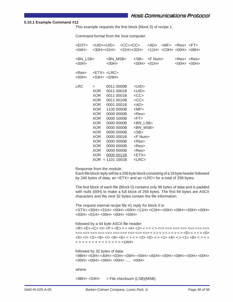
1640-IN-025-A-05 Page 46 of 56
Host Communications Protocol
Barber-Colman Company, Loves Park, IL
5.10.1 Example Command #12This example requests the first block (block 0) of recipe 1.
Command format from the host computer:
<EOT> <UID><UID> <CC><CC> <AD> <MF> <Res> <FT><04H> <30H><31H> <31H><32H> <11H> <C0H> <00H> <08H>
<BN_LSB> <BN_MSB> <SB> <F Num> <Res> <Res><00H> <00H> <00H> <01H> <00H> <00H>
<Res> <ETX> <LRC><00H> <03H> <D9H>
LRC = 0011 0000B <UID>XOR 0011 0001B <UID>XOR 0011 0001B <CC>XOR 0011 0010B <CC>XOR 0001 0001B <AD>XOR 1100 0000B <MF>XOR 0000 0000B <Res>XOR 0000 1000B <FT>XOR 0000 0000B <BN_LSB>XOR 0000 0000B <BN_MSB>XOR 0000 0000B <SB>XOR 0000 0001B <F Num>XOR 0000 0000B <Res>XOR 0000 0000B <Res>XOR 0000 0000B <Res>XOR 0000 0011B <ETX>XOR = 1101 1001B <LRC>
Response from the module:Each file block reply will be a 256 byte block consisting of a 16 byte header followedby 240 bytes of data, an <ETX> and an <LRC> for a total of 258 bytes.
The first block of each file (Block 0) contains only 96 bytes of data and is paddedwith nulls (00H) to make a full block of 256 bytes. The first 64 bytes are ASCIIcharacters and the next 32 bytes contain the file information.
The request internal recipe file #1 reply for block 0 is:<STX> <30H> <31H> <00H> <00H> <11H> <C0H> <00H> <08H> <00H> <00H><00H> <01H> <00H> <00H> <00H>
followed by a 64 byte ASCII file header:<R> <E> <C> <I> <P > <E> < > <#> <2> < > < < > <=> <=> <=> <=> <=> <=> <=><=> <=> <=> <=> <=> <=> <=> <=> <=> <=> < > > < > < > < > < > <5> < > < > <0><5> </> <2> <9> </> <9> <6> < > < > <2> <0> <:> <1> <4> <:> <1> <8> < > < >< > < > < > < > < > < > < > <1AH>
followed by 32 bytes of data:<9BH> <53H> <40H> <03H> <00H> <00H> <AEH> <00H> <08H> <00H> <00H><00H> <00H> <00H> <00H> ..... <00H>
where:
<9BH> <53H> = File checksum (LSB)(MSB)
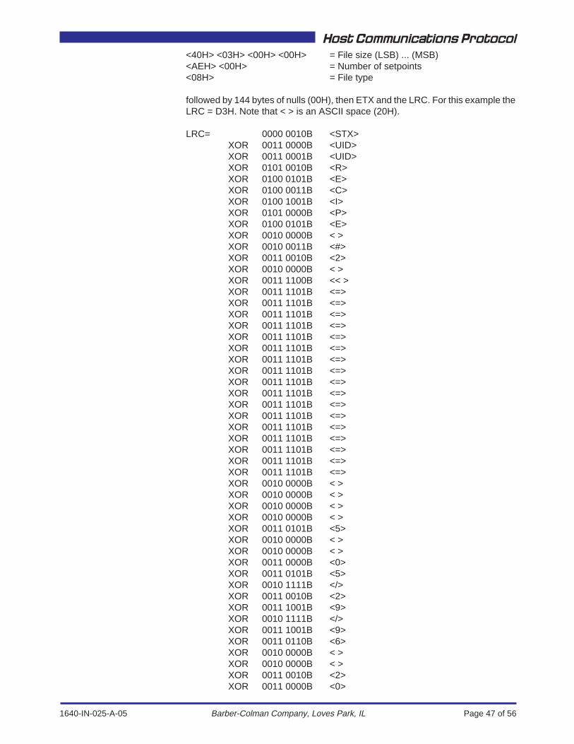
1640-IN-025-A-05 Page 47 of 56
Host Communications Protocol
Barber-Colman Company, Loves Park, IL
<40H> <03H> <00H> <00H> = File size (LSB) ... (MSB)<AEH> <00H> = Number of setpoints<08H> = File type
followed by 144 bytes of nulls (00H), then ETX and the LRC. For this example theLRC = D3H. Note that < > is an ASCII space (20H).
LRC= 0000 0010B <STX>XOR 0011 0000B <UID>XOR 0011 0001B <UID>XOR 0101 0010B <R>XOR 0100 0101B <E>XOR 0100 0011B <C>XOR 0100 1001B <I>XOR 0101 0000B <P>XOR 0100 0101B <E>XOR 0010 0000B < >XOR 0010 0011B <#>XOR 0011 0010B <2>XOR 0010 0000B < >XOR 0011 1100B << >XOR 0011 1101B <=>XOR 0011 1101B <=>XOR 0011 1101B <=>XOR 0011 1101B <=>XOR 0011 1101B <=>XOR 0011 1101B <=>XOR 0011 1101B <=>XOR 0011 1101B <=>XOR 0011 1101B <=>XOR 0011 1101B <=>XOR 0011 1101B <=>XOR 0011 1101B <=>XOR 0011 1101B <=>XOR 0011 1101B <=>XOR 0011 1101B <=>XOR 0011 1101B <=>XOR 0011 1101B <=>XOR 0010 0000B < >XOR 0010 0000B < >XOR 0010 0000B < >XOR 0010 0000B < >XOR 0011 0101B <5>XOR 0010 0000B < >XOR 0010 0000B < >XOR 0011 0000B <0>XOR 0011 0101B <5>XOR 0010 1111B </>XOR 0011 0010B <2>XOR 0011 1001B <9>XOR 0010 1111B </>XOR 0011 1001B <9>XOR 0011 0110B <6>XOR 0010 0000B < >XOR 0010 0000B < >XOR 0011 0010B <2>XOR 0011 0000B <0>
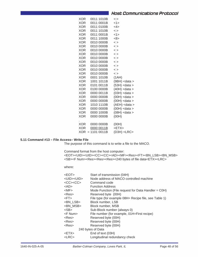
1640-IN-025-A-05 Page 48 of 56
Host Communications Protocol
Barber-Colman Company, Loves Park, IL
XOR 0011 1010B <:>XOR 0011 0001B <1>XOR 0011 0100B <4>XOR 0011 1010B <:>XOR 0011 0001B <1>XOR 0011 1000B <8>XOR 0010 0000B < >XOR 0010 0000B < >XOR 0010 0000B < >XOR 0010 0000B < >XOR 0010 0000B < >XOR 0010 0000B < >XOR 0010 0000B < >XOR 0010 0000B < >XOR 0010 0000B < >XOR 0001 1010B (1AH)XOR 1001 1011B (9BH) <data >XOR 0101 0011B (53H) <data >XOR 0100 0000B (40H) <data >XOR 0000 0011B (03H) <data >XOR 0000 0000B (00H) <data >XOR 0000 0000B (00H) <data >XOR 1010 1110B (AEH) <data >XOR 0000 0000B (00H) <data >XOR 0000 1000B (08H) <data >XOR 0000 0000B (00H).XOR 0000 0000B (00H)XOR 0000 0011B <ETX>XOR = 1101 0011B (D3H) <LRC>
5.11 Command #13 – File Access– Write FileThe purpose of this command is to write a file to the MACO.
Command format from the host computer:<EOT><UID><UID><CC><CC><AD><MF><Res><FT><BN_LSB><BN_MSB><SB><F Num><Res><Res><Res><240 bytes of file data<ETX><LRC>
where:
<EOT> Start of transmission (04H)<UID><UID> Node address of MACO controlled machine<CC><CC> Command code<AD> Function Address<MF> Mode Function (File request for Data Handler = C0H)<Res> Reserved byte (00H)<FT> File type (for example 08H= Recipe file, see Table 1)<BN_LSB> Block number, LSB<BN_MSB> Block number, MSB<SB> Sub-Block number (always 0)<F Num> File number (for example, 01H=First recipe)<Res> Reserved byte (00H)<Res> Reserved byte (00H)<Res> Reserved byte (00H)
240 bytes of Data<ETX> End of text (03H)<LRC> Longitudinal redundancy check
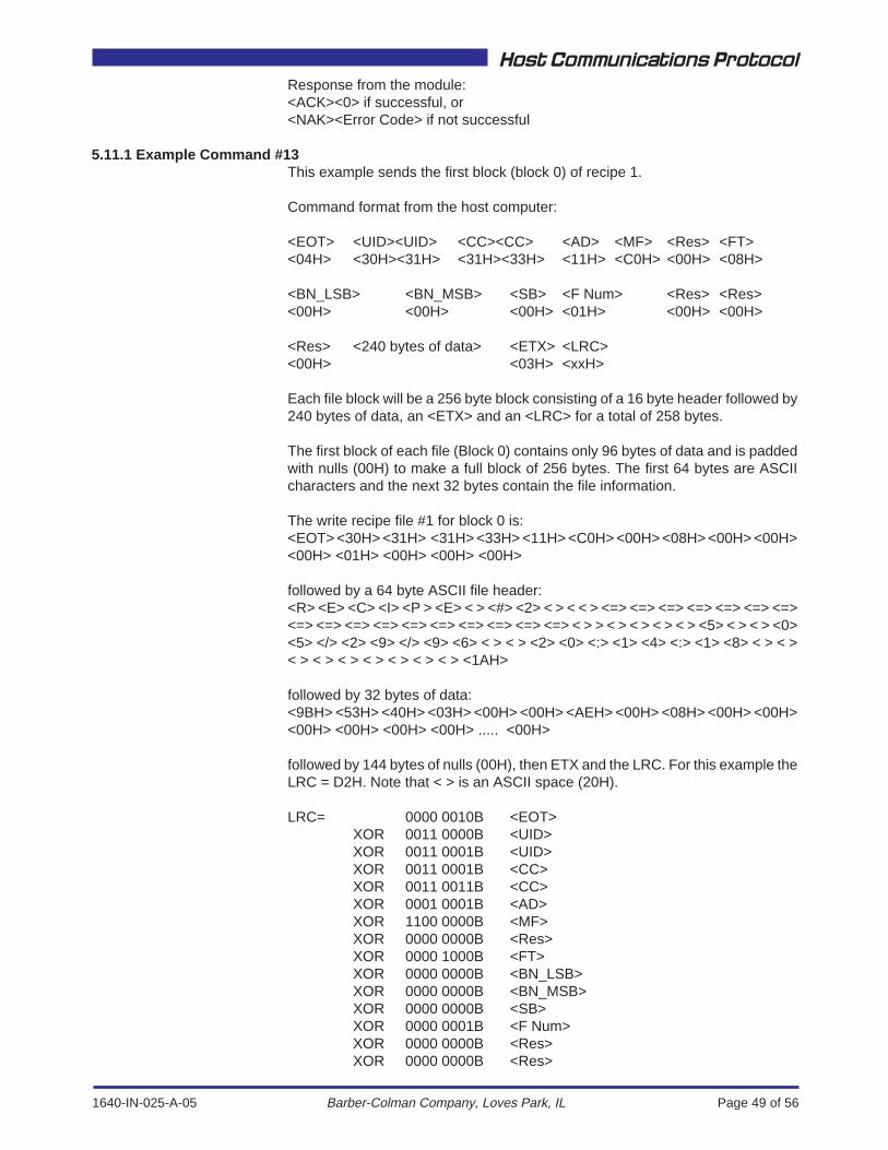
1640-IN-025-A-05 Page 49 of 56
Host Communications Protocol
Barber-Colman Company, Loves Park, IL
Response from the module:<ACK><0> if successful, or<NAK><Error Code> if not successful
5.11.1 Example Command #13This example sends the first block (block 0) of recipe 1.
Command format from the host computer:
<EOT> <UID><UID> <CC><CC> <AD> <MF> <Res> <FT><04H> <30H><31H> <31H><33H> <11H> <C0H> <00H> <08H>
<BN_LSB> <BN_MSB> <SB> <F Num> <Res> <Res><00H> <00H> <00H> <01H> <00H> <00H>
<Res> <240 bytes of data> <ETX> <LRC><00H> <03H> <xxH>
Each file block will be a 256 byte block consisting of a 16 byte header followed by240 bytes of data, an <ETX> and an <LRC> for a total of 258 bytes.
The first block of each file (Block 0) contains only 96 bytes of data and is paddedwith nulls (00H) to make a full block of 256 bytes. The first 64 bytes are ASCIIcharacters and the next 32 bytes contain the file information.
The write recipe file #1 for block 0 is:<EOT> <30H> <31H> <31H> <33H> <11H> <C0H> <00H> <08H> <00H> <00H><00H> <01H> <00H> <00H> <00H>
followed by a 64 byte ASCII file header:<R> <E> <C> <I> <P > <E> < > <#> <2> < > < < > <=> <=> <=> <=> <=> <=> <=><=> <=> <=> <=> <=> <=> <=> <=> <=> <=> < > > < > < > < > < > <5> < > < > <0><5> </> <2> <9> </> <9> <6> < > < > <2> <0> <:> <1> <4> <:> <1> <8> < > < >< > < > < > < > < > < > < > <1AH>
followed by 32 bytes of data:<9BH> <53H> <40H> <03H> <00H> <00H> <AEH> <00H> <08H> <00H> <00H><00H> <00H> <00H> <00H> ..... <00H>
followed by 144 bytes of nulls (00H), then ETX and the LRC. For this example theLRC = D2H. Note that < > is an ASCII space (20H).
LRC= 0000 0010B <EOT>XOR 0011 0000B <UID>XOR 0011 0001B <UID>XOR 0011 0001B <CC>XOR 0011 0011B <CC>XOR 0001 0001B <AD>XOR 1100 0000B <MF>XOR 0000 0000B <Res>XOR 0000 1000B <FT>XOR 0000 0000B <BN_LSB>XOR 0000 0000B <BN_MSB>XOR 0000 0000B <SB>XOR 0000 0001B <F Num>XOR 0000 0000B <Res>XOR 0000 0000B <Res>
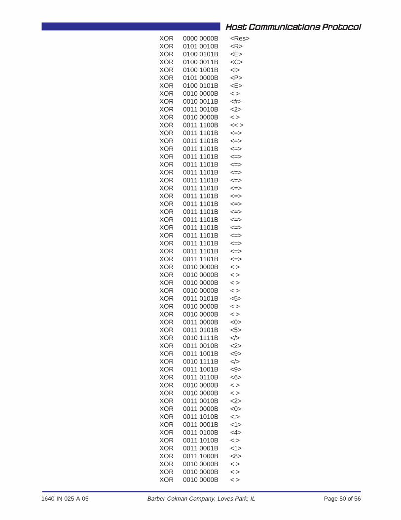
1640-IN-025-A-05 Page 50 of 56
Host Communications Protocol
Barber-Colman Company, Loves Park, IL
XOR 0000 0000B <Res>XOR 0101 0010B <R>XOR 0100 0101B <E>XOR 0100 0011B <C>XOR 0100 1001B <I>XOR 0101 0000B <P>XOR 0100 0101B <E>XOR 0010 0000B < >XOR 0010 0011B <#>XOR 0011 0010B <2>XOR 0010 0000B < >XOR 0011 1100B << >XOR 0011 1101B <=>XOR 0011 1101B <=>XOR 0011 1101B <=>XOR 0011 1101B <=>XOR 0011 1101B <=>XOR 0011 1101B <=>XOR 0011 1101B <=>XOR 0011 1101B <=>XOR 0011 1101B <=>XOR 0011 1101B <=>XOR 0011 1101B <=>XOR 0011 1101B <=>XOR 0011 1101B <=>XOR 0011 1101B <=>XOR 0011 1101B <=>XOR 0011 1101B <=>XOR 0011 1101B <=>XOR 0010 0000B < >XOR 0010 0000B < >XOR 0010 0000B < >XOR 0010 0000B < >XOR 0011 0101B <5>XOR 0010 0000B < >XOR 0010 0000B < >XOR 0011 0000B <0>XOR 0011 0101B <5>XOR 0010 1111B </>XOR 0011 0010B <2>XOR 0011 1001B <9>XOR 0010 1111B </>XOR 0011 1001B <9>XOR 0011 0110B <6>XOR 0010 0000B < >XOR 0010 0000B < >XOR 0011 0010B <2>XOR 0011 0000B <0>XOR 0011 1010B <:>XOR 0011 0001B <1>XOR 0011 0100B <4>XOR 0011 1010B <:>XOR 0011 0001B <1>XOR 0011 1000B <8>XOR 0010 0000B < >XOR 0010 0000B < >XOR 0010 0000B < >
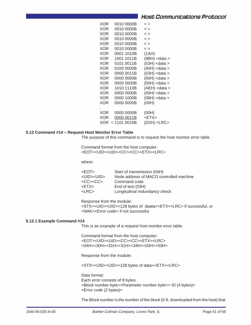
1640-IN-025-A-05 Page 51 of 56
Host Communications Protocol
Barber-Colman Company, Loves Park, IL
XOR 0010 0000B < >XOR 0010 0000B < >XOR 0010 0000B < >XOR 0010 0000B < >XOR 0010 0000B < >XOR 0010 0000B < >XOR 0001 1010B (1AH)XOR 1001 1011B (9BH) <data >XOR 0101 0011B (53H) <data >XOR 0100 0000B (40H) <data >XOR 0000 0011B (03H) <data >XOR 0000 0000B (00H) <data >XOR 0000 0000B (00H) <data >XOR 1010 1110B (AEH) <data >XOR 0000 0000B (00H) <data >XOR 0000 1000B (08H) <data >XOR 0000 0000B (00H).XOR 0000 0000B (00H)XOR 0000 0011B <ETX>XOR = 1101 0010B (D2H) <LRC>
5.12 Command #14 – Request Host Monitor Error TableThe purpose of this command is to request the host monitor error table.
Command format from the host computer:<EOT><UID><UID><CC><CC><ETX><LRC>
where:
<EOT> Start of transmission (04H)<UID><UID> Node address of MACO controlled machine<CC><CC> Command code<ETX> End of text (03H)<LRC> Longitudinal redundancy check
Response from the module:<STX><UID><UID><128 bytes of daata><ETX><LRC> if successful, or<NAK><Error code> if not successful.
5.12.1 Example Command #14This is an example of a request host monitor error table.
Command format from the host computer:<EOT><UID><UID><CC><CC><ETX><LRC><04H><30H><31H><31H><34H><03H><03H>
Response from the module:
<STX><UID><UID><128 bytes of data><ETX><LRC>
Data format:Each error consists of 8 bytes:<Block number byte><Parameter number byte>< ID (4 bytes)><Error code (2 bytes)>
The Block number is the number of the block (0-9, downloaded from the host) that

1640-IN-025-A-05 Page 52 of 56
Host Communications Protocol
Barber-Colman Company, Loves Park, IL
holds the parameter that generated the error. The Parameter number is thenumber of the parameter (0-59, within the block). The ID is the parameter ID(consisting of AD, FN, TYU and TYL). The last 2 bytes contain the error code (fromSections 4.7 and 4.7.1 of this manual).
5.13 Command #15 – Data Handler Host CommandThe purpose of this command is to send a system command to the Data Handler.
Command format from the host computer:<EOT><UID><UID><CC><CC><CMD><ETX><LRC>
where:
<EOT> Start of transmission (04H)<UID><UID> Node address of MACO controlled machine<CC><CC> Command code<CMD> Data Handler command (see Table 2)<ETX> End of text (03H)<LRC> Longitudinal redundancy check
Response from the module:<ACK><0> if successful, or<NAK><Error Code> if not successful.
5.13.1 Example Command #16This is an example of a "copy recipe" data handler host command.
Command format from the host computer:<EOT><UID><UID><CC><CC><CMD<ETX><LRC><04H><30H><31H><31H><35H><17H<03H><15H>
Response from the module:<ACK><0>
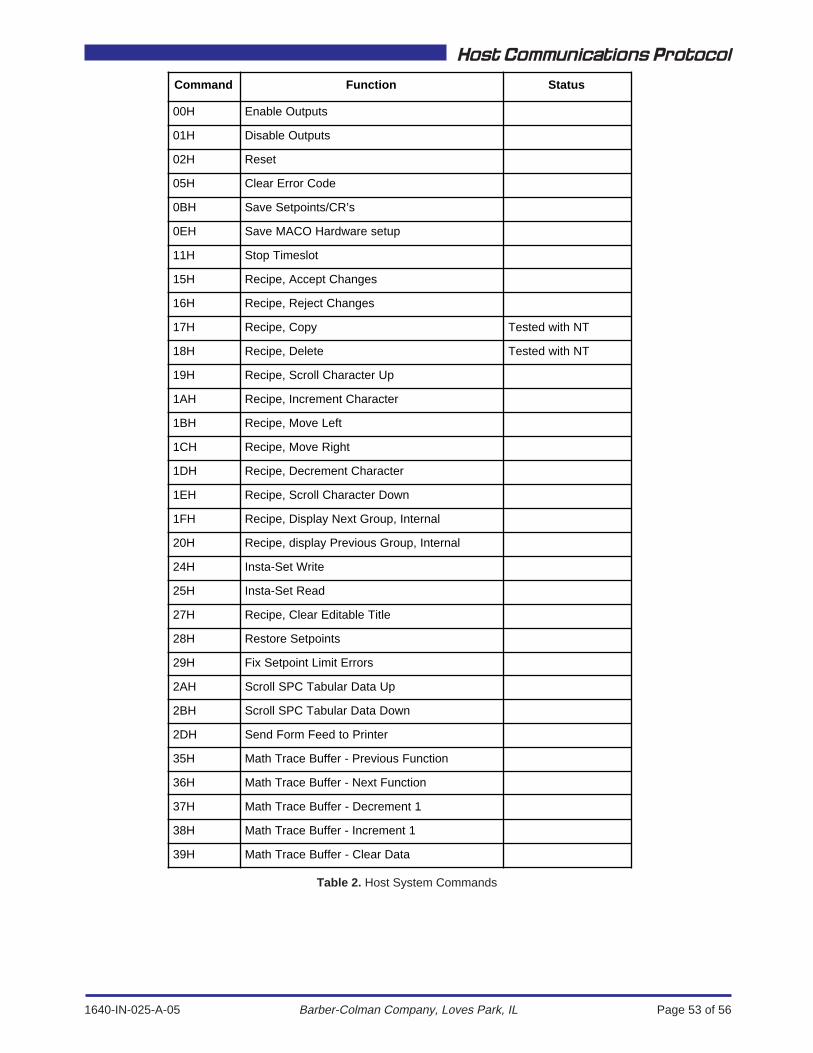
1640-IN-025-A-05 Page 53 of 56
Host Communications Protocol
Barber-Colman Company, Loves Park, IL
Command Function Status
00H Enable Outputs
01H Disable Outputs
02H Reset
05H Clear Error Code
0BH Save Setpoints/CR’s
0EH Save MACO Hardware setup
11H Stop Timeslot
15H Recipe, Accept Changes
16H Recipe, Reject Changes
17H Recipe, Copy Tested with NT
18H Recipe, Delete Tested with NT
19H Recipe, Scroll Character Up
1AH Recipe, Increment Character
1BH Recipe, Move Left
1CH Recipe, Move Right
1DH Recipe, Decrement Character
1EH Recipe, Scroll Character Down
1FH Recipe, Display Next Group, Internal
20H Recipe, display Previous Group, Internal
24H Insta-Set Write
25H Insta-Set Read
27H Recipe, Clear Editable Title
28H Restore Setpoints
29H Fix Setpoint Limit Errors
2AH Scroll SPC Tabular Data Up
2BH Scroll SPC Tabular Data Down
2DH Send Form Feed to Printer
35H Math Trace Buffer - Previous Function
36H Math Trace Buffer - Next Function
37H Math Trace Buffer - Decrement 1
38H Math Trace Buffer - Increment 1
39H Math Trace Buffer - Clear Data
Table 2. Host System Commands
1640-IN-025-A-05 Page 54 of 56
Host Communications Protocol
Barber-Colman Company, Loves Park, IL
1640-IN-025-A-05 Page 55 of 56
Host Communications Protocol
Barber-Colman Company, Loves Park, IL
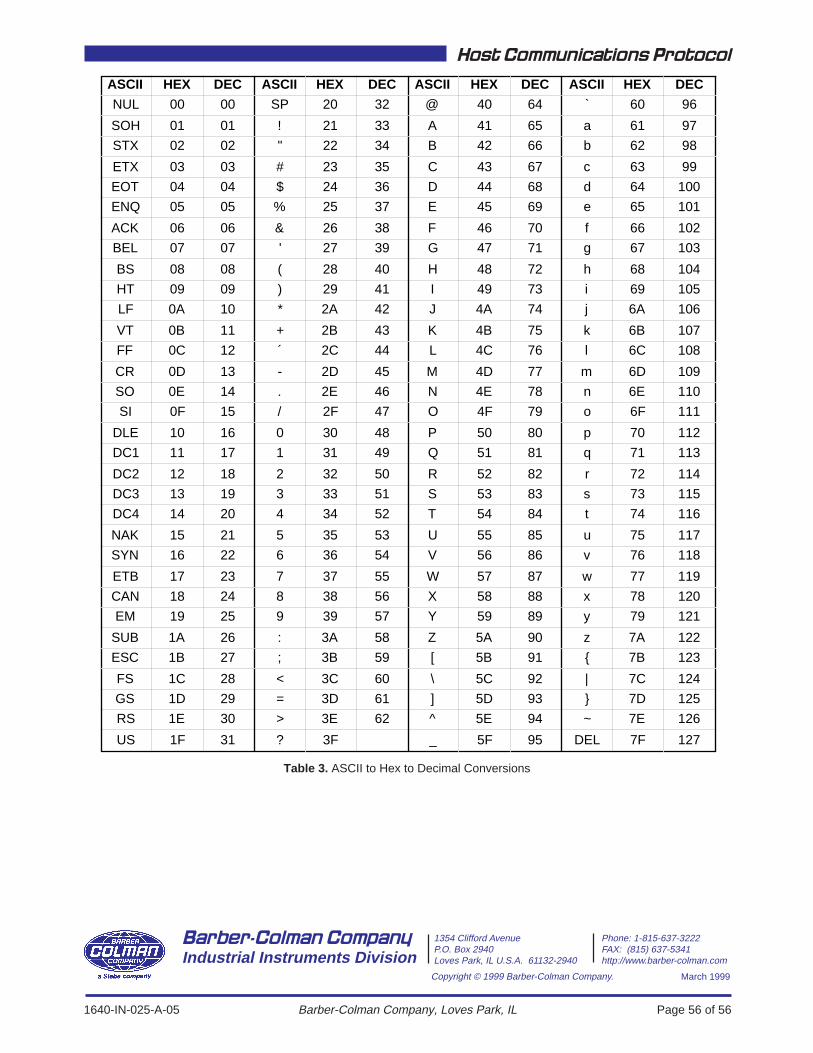
1640-IN-025-A-05 Page 56 of 56
Host Communications Protocol
Barber-Colman Company, Loves Park, IL
Copyright © 1999 Barber-Colman Company.
Barber-Colman CompanyIndustrial Instruments Division
1354 Clifford Avenue Phone: 1-815-637-3222P.O. Box 2940 FAX: (815) 637-5341Loves Park, IL U.S.A. 61132-2940 http://www.barber-colman.com
March 1999
ASCII HEX DEC ASCII HEX DEC ASCII HEX DEC ASCII HEX DEC
NUL 00 00 SP 20 32 @ 40 64 ` 60 96
SOH 01 01 ! 21 33 A 41 65 a 61 97
STX 02 02 " 22 34 B 42 66 b 62 98
ETX 03 03 # 23 35 C 43 67 c 63 99
EOT 04 04 $ 24 36 D 44 68 d 64 100
ENQ 05 05 % 25 37 E 45 69 e 65 101
ACK 06 06 & 26 38 F 46 70 f 66 102
BEL 07 07 ' 27 39 G 47 71 g 67 103
BS 08 08 ( 28 40 H 48 72 h 68 104
HT 09 09 ) 29 41 I 49 73 i 69 105
LF 0A 10 * 2A 42 J 4A 74 j 6A 106
VT 0B 11 + 2B 43 K 4B 75 k 6B 107
FF 0C 12 ´ 2C 44 L 4C 76 l 6C 108
CR 0D 13 - 2D 45 M 4D 77 m 6D 109
SO 0E 14 . 2E 46 N 4E 78 n 6E 110
SI 0F 15 / 2F 47 O 4F 79 o 6F 111
DLE 10 16 0 30 48 P 50 80 p 70 112
DC1 11 17 1 31 49 Q 51 81 q 71 113
DC2 12 18 2 32 50 R 52 82 r 72 114
DC3 13 19 3 33 51 S 53 83 s 73 115
DC4 14 20 4 34 52 T 54 84 t 74 116
NAK 15 21 5 35 53 U 55 85 u 75 117
SYN 16 22 6 36 54 V 56 86 v 76 118
ETB 17 23 7 37 55 W 57 87 w 77 119
CAN 18 24 8 38 56 X 58 88 x 78 120
EM 19 25 9 39 57 Y 59 89 y 79 121
SUB 1A 26 : 3A 58 Z 5A 90 z 7A 122
ESC 1B 27 ; 3B 59 [ 5B 91 { 7B 123
FS 1C 28 < 3C 60 \ 5C 92 | 7C 124
GS 1D 29 = 3D 61 ] 5D 93 } 7D 125
RS 1E 30 > 3E 62 ^ 5E 94 ~ 7E 126
US 1F 31 ? 3F _ 5F 95 DEL 7F 127
Table 3. ASCII to Hex to Decimal Conversions