hoshizaki · nbr = nitrile butadiene rubber nr = natural rubber np = neoprene si.r = silicone...
TRANSCRIPT
Hoshizaki
“A Superior Degreeof Reliability”
www.hoshizaki.com
ModelKM-1301SAH-E
Stackable Crescent Cuber
Hoshizaki America, Inc.
Number: 71296Issued: 3-13-2009Revised: 8-5-2009
PARTS LIST
™
89/33673/23

�
CONTENTSAuxiliary Codes ...................................................................................................................... 3Note About Ordering Parts .................................................................................................... 3Material Abbreviations ........................................................................................................... 4A. Ice Cuber Assembly .......................................................................................................... 5B. Refrigeration Circuit .......................................................................................................... 8C. Water Circuit ................................................................................................................... 1�D. Control Box Assembly ..................................................................................................... 15E. Transformer Box Assembly ............................................................................................. 17F. Label Location ................................................................................................................. 18G. Evaporator Assembly ...................................................................................................... �0H. Pump Motor Assembly .................................................................................................... �1J. Accessories & Packaging ................................................................................................ ��

3
Auxiliary Codes
KM-1301SAH-E T-0 December �008 U-0 February �009 U-1 September �009
Auxiliary Code BreakdownThe auxiliary code is the first two characters in the serial number. The first character indicates the year. Years progress or regress in alphabetical order. The series runs from "A" through "V" and the letters "I" and "O" are skipped. The second character indicates significant part changes within a year. Base is "0" and this number advances for each change.
Note About Ordering PartsMost assemblies cannot be ordered as complete units; parts in the assemblies generally must be ordered separately.
IMPORTANTIEC standards require that the clamping means of earthing terminals be adequately secured against accidental loosening and that accessible metal parts of the icemaker which may become live in the event of an insulation fault be permanently and reliably connected to an earthing terminal within the icemaker or to the earthing contact of the icemaker inlet. This is accomplished in this icemaker through the use of stainless steel lock washers.
4
Material AbbreviationsALUMINUM AL = Aluminum
COPPER CU = Copper
PLASTIC ABS = Acrylonitrile -butadiene -styrene AC = Polyacetal EVA = Ethylene vinyl acetate PA = Polyamide = Nylon PC = Polycarbonate PE = Polyethylene PES = Polyester PETP = Polyethylene terephthalate = Tetlon PP = Polypropylene PS = Polystyrene PTFE = Polytetrafluoroethylene = Teflon PUR = Polyurethane PVC = Polyvinyl chloride
RUBBER VN = Vinyl Nitrile EPDM = EP rubber NBR = Nitrile butadiene rubber NR = Natural rubber NP = Neoprene SI.R = Silicone rubber SY.R = Synthetic rubber EPH = Epichlorohydrin
STEEL GS = Galvanized steel SS = Stainless steel PS = Plated steel PAS = Primed steel

5
A. Ice Cuber AssemblyKM-1301SAH-E
T-0 to U-1
1
10
BC
D D1
E E1
F
�a�
43
5
6a6
7a78
9a9
13
14
�1�0�� 16
�3
1� 1�a
17 17a
�4 �4a
11 11a
15 15a
D�
�b
6b1�b
17b
18 18a 18b
19 19a 19b
�5 �5a
�6
For Thermostat, see"D. Control Box Assembly"

6
Title: A. Ice Cuber Assembly Model: KM-1301SAH-E
Index No. Description
Material or Model Number Part Number
Required Number
T-0U-0 U-1
B Refrigeration Circuit - 1A1655A01 1 1
C Water Circuit - 1A1674A01 1 1
D Control Box Assembly - �A4863A01 1 -
�A4863A0� 1
D1 T� Screw 4×8 7P31-0408 3 3
D� Split Lock Washer M4, SS 7L��-0400 3 3
E Transformer Box Assembly - 3343�4A01 1 1
E1 Hex Head Bolt w/Washer (LF) 5×1�, SS 7B0�3051� 4 4
F Label Location - �A4754A01 1 -
�A4754A0� 1
1 Evaporator Case - 1A0603G06 1 1
� Control Box Cover - 3A�386-01 1 1
�a T� Screw 4×8 7P31-0408 � �
�b Split Lock Washer M4, SS 7L��-0400 � �
3 Square Washer Brass 433537-0� 1 1
4 Screw-Grounding - 433304-0� 1 1
5 Bushing SR-34-� 4�047�-05 1 1
6 Junction Box Cover - 4A1767-01 1 1
6a T� Screw 4×8 7P31-0408 1 1
6b Split Lock Washer M4, SS 7L��-0400 1 1
7 Bulb Holder - 3A3903-01 1 1
7a Truss Head Screw 4×10, SS 7C3�-0410 � �
8 Spacer ABS 4397�7-01 1 1
9 Bulb Holder (C) �16340G01 1 1
9a Truss Head Screw 4×1�, SS 7C3�-041� � �
10 Capillary Ring - 4�5307-01 1 1
11 Bulb Holder (D) - 3�874�-01 1 1
11a Thumbscrew Black 415949G1� � �
1� Front Panel Bracket 3�3903-01 1 1
1�a T� Screw 4×1�, SS 7P3�-041� � �
1�b Split Lock Washer M4, SS 7L��-0400 � �
13 Spacer ABS 3�43�1-01 1 1
14 Top Insulation - 3�4�16G01 1 1
15 Front Insulation - 3�4�15G01 1 1
15a Thumbscrew Black 415949G1� 1 1
16 Gasket L=1�19 4A0808L0� 1 1
17 Side Panel (R) - �A���6G01 1 1
17a Truss Head Screw 4×8, SS 7C3�-0408 1 1
17b Split Lock Washer M4, SS 7L��-0400 1 1
18 Top Panel - �A��55-01 1 1
18a Truss Head Screw 4×8, SS 7C3�-0408 � �
18b Split Lock Washer M4, SS 7L��-0400 � �
19 Front Panel - �A���4-0� 1 1
19a Truss Head Screw 4×16, SS 7C3�-0416 � �
19b Split Lock Washer M4, SS 7L��-0400 � �
�0 Louver - 1A0548-01 4 4
�1 Push Retainer - 4A�414-01 1� 1�

7
Title: A. Ice Cuber Assembly Model: KM-1301SAH-E
Index No. Description
Material or Model Number Part Number
Required Number
T-0U-0 U-1
�� Air Filter - �A�063G01 4 4
�3 Silicone Hose L=�85 7730I381� 1 1
�4 Thermostat Extension Bracket SS 3A0408-01 1 1
�4a T� Screw 4×1�, SS 7P3�-041� � �
�5 Terminal Block - 4A10�6-01 1 1
�5a Pan Head Screw (S) 3×16, SS 7C1�-0316 � �
�6 Clamp - 4A0337-1� 1 1

8
B. Refrigeration Circuit1/2KM-1301SAH-E
T-0 to U-1
1a1
3
�a �b �c�
G
�� ��a
�8�1a�1
15
�3 �3a
�4 �4a
�5 �5a
�6 �6a
�7 �7a
�9 �9a
47 47a45 46
48
49
50
51
3�50
3031
Detailed TXV Bulb Attachment Detailed Thermistor Attachment
1718
19
50
5� 5�a 5�b
47b
�1b
��b
�9b
�3b
1b
�5b
�4b

9
B. Refrigeration Circuit2/2KM-1301SAH-E
T-0 to U-1
4
5
6
7
8
910
11
1�
13
14
�0 3533
34
39b39 39a
36 36a
38 38a
4� 4�a
44 44a
37
40 41
43
39b39 39a
16
4�b
36b
38b
39c
44b
39c

10
Title: B. Refrigeration Circuit Model: KM-1301SAH-E
Index No. Description
Material or Model Number Part Number
Required Number
T-0 to U-1
G Evaporator Assembly - 104696G03 1
1 Condenser - �136�1-01 1
1a T� Screw 4×8 7P31-0408 �
1b Split Lock Washer M4, SS 7L��-0400 �
� Compressor CS14K6E-PFJ-�37 4A1749-01 1
�a Spacer - 4349�1-01 4
�b Grommet - 4349��-01 4
�c Hex Head Bolt w/Washer 8×45 437889-01 4
3 Connection Tee Cover - 4A1379-01 1
4 Copper Tube (A)-Expansion Valve
- 3A5061G01 1
5 Copper Tube (A)-Low Side - 3A505�G01 1
6 Copper Tube (B)-High Side - �A48�6G01 1
7 Copper Tube (D)-High Side - 4A09�1-01 1
8 Copper Tube (F)-High Side - 4A46�3-01 1
9 Copper Tube (L)-Hot Gas - �A4814G0� 1
10 Copper Tube (R)-Hot Gas - �A4815G0� 1
11 Copper Tube (Z)-High Side - 4A4635-01 1
1� Copper Tube-Hot Gas - 3A0�1�G01 1
13 Copper Tube-Line Valve - 3A�31�-01 1
14 Copper Tube-Service Valve - 4A46�4-01 1
15 Expansion Valve Cover - 3A0944-01 �
16 Expansion Valve - 4A148�-01 �
17 Holder-Expansion Valve - 3A0107-01 �
18 Clamp - 443461-0� �
19 Insulation Tubing L=150 776�-3555 �
�0 Heat Exchanger - �A4816G01 1
�1 Front Frame - 3A4635-01 1
�1a T� Screw 4×8 7P31-0408 4
�1b Split Lock Washer M4, SS 7L��-0400 4
�� Side Frame (A) - �1947�G01 1
��a T� Screw 4×8 7P31-0408 3
��b Split Lock Washer M4, SS 7L��-0400 3
�3 Side Frame(B) - 3A30�7-01 1
�3a T� Screw 4×8 7P31-0408 4
�3b Split Lock Washer M4, SS 7L��-0400 4
�4 Rear Frame - 4A0883G01 1
�4a T� Screw 4×8 7P31-0408 4
�4b Split Lock Washer M4, SS 7L��-0400 4
�5 Shroud - �A4861-01 1
�5a T� Screw 4×8 7P31-0408 6
�5b Split Lock Washer M4, SS 7L��-0400 6
�6 Fan Motor Bracket - 3�7180-01 1
�6a Hex Head Bolt w/Washer (LF) 5×1�, SS 7B0�3051� 4
�7 Fan Motor 50 Watt-GEHI 4A3158-01 1
�7a Self-Locking Nut 8-3� 7N�1I083� 4

11
Title: B. Refrigeration Circuit Model: KM-1301SAH-E
Index No. Description
Material or Model Number Part Number
Required Number
T-0 to U-1
�8 Fan Blade - 4A3959-01 1
�9 Capacitor 5.0MFD, �50VAC
44319�-0� 1
�9a T� Screw 4×10 7P31-0410 1
�9b Split Lock Washer M4, SS 7L��-0400 1
30 Holder-Thermistor - 4�7430-01 1
31 Thermistor L=1050 4�9006-03 1
3� Insulation-Thermistor - 4�7441-01 1
33 Check Valve - 4A1373-01 �
34 Strainer - 441569-0� 1
35 Valve Body-Hot Gas - 4A3978-01 1
36 Hot Gas Valve Bracket - 44�16�-01 1
36a T� Screw 4×8 7P31-0408 �
36b Split Lock Washer M4, SS 7L��-0400 �
37 Valve Body-Line - 4A3�76-01 1
38 Line Valve Bracket - 4A1406-01 1
38a T� Screw 4×8 7P31-0408 �
38b Split Lock Washer M4, SS 7L��-0400 �
39 Coil-Valve - 4A3�77-01 �
39a Bolt - 4A3�77F01 �
39b Truss Head Screw 4×8 7C31-0408 4
39c Split Lock Washer M4, SS 7L��-0400 4
40 Drier - 4A�666-01 1
41 Nylon Tie PLWP3H-TL 8911-0301 1
4� Service Valve - 4A34�0-01 �
4�a Hex Head Tapping Screw 1/4-�0×1/� 7B03I141� �
4�b Split Lock Washer M8, SS 7L��-0800 �
43 Pressure Switch - 433441-07 1
44 Pressure Switch Bracket - 434938-01 1
44a T� Screw 4×8 7P31-0408 1
44b Split Lock Washer M4, SS 7L��-0400 1
45 Insulation - 436671-01 1
46 Insulated Rubber Tube - 3�3975G01 1
47 Insulation Holder - 3A0979-01 1
47a T� Screw 4×8, SS 7P3�-0408 �
47b Split Lock Washer M4, SS 7L��-0400 �
48 Insulation Tubing L=40 776�-10�0 1
49 Wire Saddle - 4A0338-0� 3
50 Cable Tie CV-�00 8911-0�00 15
51 Clamp - 4A�338-01 1
5� Frame Seal Black EPDM 3�39�5-01 4
5�a T� Screw 4×1�, SS 7P3�-041� 4
5�b Split Lock Washer M4, SS 7L��-0400 4

1�
C. Water CircuitKM-1301SAH-E
T-0 to U-1
1 1a
H1H
�
3a3
5
6
8
9
10
11
11
1�
1�
13
14
15
16
17
18
19
�0
�1
��
�4
�5
�6�7 �7a
31 31a
30
3�
�9
343536
37
38
39
40
414�
43
�3
4 4a
44
�8
45
7
1�
15
19
33 33a
7 1�H�
1b
3b
31b

13
Title: C. Water Circuit Model: KM-1301SAH-E
Index No. Description
Material or Model Number Part Number
Required Number
T-0 to
U-1
H Pump Motor Assembly S-086� �1569�A04 1
H1 Truss Head Screw 5×8, SS 7C3�-0508 �
H� Split Lock Washer M5, SS 7L��-0500 �
1 Water Supply Pipe - 4A0768G01 1
1a T� Screw 4×8 7P31-0408 �
1b Split Lock Washer M4, SS 7L��-0400 �
� Rubber Gasket - 413854-03 1
3 Water Valve Bracket - 3A�685-01 1
3a T� Screw 4×8 7P31-0408 1
3b Split Lock Washer M4, SS 7L��-0400 1
4 Water Valve 1�6756-0 4A1176-0� 1
4a Truss Head Screw 4×8, SS 7C3�-0408 �
5 Distributor - 438�76G01 1
6 Hose Clamp 18mm, SS 4�7443-05 1
7 Hose Clamp 3�mm, SS 4�7443-09 �
8 Distributor Assembly - 4A1175G01 1
9 Distributor Hose (A) - 3�5738-01 1
10 Distributor Hose (B) - 3�5738-0� 1
11 Distributor Hose (C) - 3�3985-01 �
1� Hose Clamp �5mm, SS 4�7443-03 7
13 Joint Pipe - 439�97-01 1
14 Hose Clamp 13.5mm, SS 4�7443-07 6
15 Spray Tube - 437049G01 6
16 Spray Guide - �08586-01 18
17 Separator (A) - �136��-01 �
18 Separator (B) - �A0100-01 �
19 Cube Guide - �14�43-01 �
�0 Hose (A) Black, EPDM 435091-01 1
�1 Hose (B) - 436599-01 1
�� Vinyl Hose L=415 7716-�73� 1
�3 Bushing SB-1500-�1 4�0470-06 �
�4 "O" Ring - 7611-G035 1
�5 Spring - 3��110-01 1
�6 Valve Seat Black, EPDM 433705-01 1
�7 Valve Housing-Drain ABS, White 3�3613-01 1
�7a T� Screw 4×10, SS 7P3�-0410 3
�8 Overflow Cap - 3�3978-01 1
�9 Joint-Overflow - 3�39�3-0� 1
30 "O" Ring - 7611-P018 1
31 Float Switch Bracket SS 3A0449-01 1
31a T� Screw 4×8, SS 7P3�-0408 �
31b Split Lock Washer M4, SS 7L��-0400 �
3� Connector-Float Switch - 4�6799-04 1
33 Float Switch - 4A36�4-01 1
33a Truss Head Screw 4×10, SS 7C3�-0410 �
34 Silicone Hose L=140 7730I381� 1

14
Title: C. Water Circuit Model: KM-1301SAH-E
Index No. Description
Material or Model Number Part Number
Required Number
T-0 to
U-1
35 Silicone Hose L=390 7730I3896 1
36 Clamp 4�53 4�790�-05 1
37 Insulation Tube L=80 776�-3555 1
38 Insulation Tube L=1�0 776�-3555 1
39 Insulation Tube L=150 776�-3555 1
40 Drain Hose - 3�4757-01 1
41 Joint Hose - 439�96-0� 1
4� Flange - 439�67-0� 1
43 Drain Plug - 309�46-01 1
44 "O" Ring - 7611-P015 1
45 Wire Saddle - 4A0338-0� 7
15
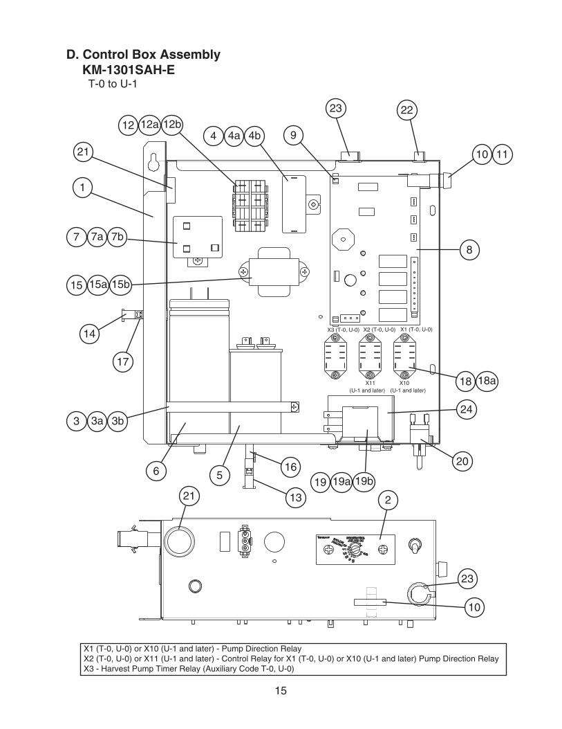
X1 (T-0, U-0) or X10 (U-1 and later) - Pump Direction RelayX� (T-0, U-0) or X11 (U-1 and later) - Control Relay for X1 (T-0, U-0) or X10 (U-1 and later) Pump Direction RelayX3 - Harvest Pump Timer Relay (Auxiliary Code T-0, U-0)
D. Control Box AssemblyKM-1301SAH-E
T-0 to U-1
1
�3
�
4a4
3a3
56
7a78
91�a1�
16
14
13
17
�1
�0
���3
1110
15a15
18a18
19a19
�1
10
3b
4b
7b
1�b
15b
19b
�4
X� (T-0, U-0) X1 (T-0, U-0)
X11 (U-1 and later)
X3 (T-0, U-0)
X10 (U-1 and later)

16
Title: D. Control Box Assembly Model: KM-1301SAH-E
Index No. Description
Material or Model Number Part Number
Required Number
T-0U-0 U-1
1 Control Box - �A4864G01 1 1
� Control Label - 4A1758-01 1 1
3 Strap - 4A��6�-04 1 1
3a T� Screw 4×8 7P31-0408 1 1
3b Split Lock Washer M4, SS 7L��-0400 1 1
4 Capacitor-Pump Motor 15.0MFD, �50VAC
4A�1�8-0� 1 1
4a T� Screw 4×8 7P31-0408 1 1
4b Split Lock Washer M4, SS 7L��-0400 1 1
5 Capacitor-Run 35MFD, 440VAC
3A�005-1� 1 1
6 Capacitor-Start 160MFD, 330VAC
4A1094-01 1 1
7 Starter (Relay) - 4A1107-13 1 1
7a T� Screw 4×8 7P31-0408 1 1
7b Split Lock Washer M4, SS 7L��-0400 1 1
8 Control Board - �A379�-01 1 1
9 Board Support - 4A0336-03 4 4
10 Fuse 10A, �50V 4A0893-07 � �
11 Fuse Holder 1/4×1-1/4 4A3449-01 1 1
1� Magnetic Contactor - 4�8393-01 1 1
1�a T� Screw 4×8 7P31-0408 � �
1�b Split Lock Washer M4, SS 7L��-0400 � �
13 Plug Housing 3P 41�83�-06 1 1
14 Plug Housing �P 41�83�-07 1 1
15 Transformer - 3A017�-01 1 1
15a T� Screw 4×8 7P31-0408 � �
15b Split Lock Washer M4, SS 7L��-0400 � �
16 Receptacle Housing 3P 41�831-06 1 1
17 Receptacle Housing �P 41�831-07 1 1
18 Relay(X1, X�, and X3 - T-0 and U-0) (X10 and X11 - U-1 and later)
- 40613�-07 3 �
18a Tapping Screw 3×8 431415-01 6 4
19 Thermostat - 4A�879-0� 1 1
19a Truss Head Screw 4×6 7C31-0406 � �
19b Split Lock Washer M4, SS 7L��-0400 � �
�0 Toggle Switch - 4A�436-01 1 1
�1 Bushing SB-1093-15 4�0470-03 � �
�� Bushing OCB-500 4�8394-0� 1 1
�3 Bushing OCB-875 4�8394-04 � �
�4 Barrier - 4A1096-01 1 1
Note: For Fan Capacitor, see the Refrigeration Circuit in this manual.

17
E. Transformer Box AssemblyKM-1301SAH-E
T-0 to U-1
Title: E. Transformer Box Assembly Model: KM-1301SAH-E
Index No. Description
Material or Model Number Part Number
Required Number
T-0 to
U-1
1 Transformer - 4474�0-01 1
1a Truss Head Screw 4×8 7C31-0408 4
1b Split Lock Washer M4, SS 7L��-0400 4
� Transformer Bracket - 447955-01 1
3 Transformer Cover - 447956-01 1
3a T� Screw 4×8 7P31-0408 �
3b Split Lock Washer M4, SS 7L��-0400 �
4 Bushing OCB-500 4�8394-0� 1
1a1
�
1b
3a3 3b
4

18
F. Label LocationKM-1301SAH-E
T-0 to U-1
View "A"
Control Box
A
1
�4
3
5
6
7
8
9
11
10
14
15
1317
16
7
1�
18

19
Title: F. Label Location Model: KM-1301SAH-E
Index No. Description
Material or Model Number Part Number
Required Number
T-0U-0 U-1
1 Emblem - 4A0560-01 1 1
� Label-Penguin (R) - 4A05�6-01 1 1
3 Label-Air Filter - 4�6177-01 1 1
4 Maintenance Label - 3A5010-01 1 1
5 Caution Label (K) - 439150-01 1 1
6 Label-R404A - 4A0960-01 1 1
7 Nameplate - 1A1591-07 � �
8 Wiring Label - 3A5008-01 1 -
3A5541-01 1
9 Manual Label - 3�4476-01 1 1
10 Manual Label-Bin Control - 3A4841-01 1 1
11 Label-Main Connection - 4A1169-01 1 1
1� Process Valve Label - 4A3943-01 1 1
13 Label-Alarm - 4A3517-01 1 1
14 Instruction Label - 444575-01 1 1
15 Caution Label (F) - 439146-01 1 1
16 Label-Control Board - 3A4799-01 1 1
17 Label-Fuse - 4A�817-01 1 1
18 Water Supply Label - 4A1158-01 1 1
�0
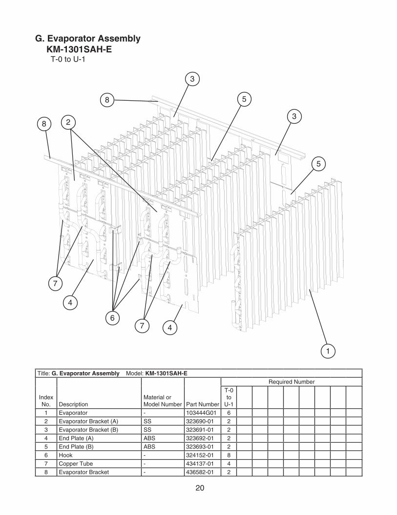
G. Evaporator AssemblyKM-1301SAH-E
T-0 to U-1
Title: G. Evaporator Assembly Model: KM-1301SAH-E
Index No. Description
Material or Model Number Part Number
Required Number
T-0 to
U-1
1 Evaporator - 103444G01 6
� Evaporator Bracket (A) SS 3�3690-01 �
3 Evaporator Bracket (B) SS 3�3691-01 �
4 End Plate (A) ABS 3�369�-01 �
5 End Plate (B) ABS 3�3693-01 �
6 Hook - 3�415�-01 8
7 Copper Tube - 434137-01 4
8 Evaporator Bracket - 43658�-01 �
1
�
4
3
5
6
8
7
4
3
5
7
8

�1
H. Pump Motor AssemblyKM-1301SAH-E
T-0 to U-1
Title: H. Pump Motor Assembly Model: KM-1301SAH-E
Index No. Description
Material or Model Number Part Number
Required Number
T-0 to
U-1
1 Pump Motor M91A60SP�01 �U0106-01 1
� Pump Flange - �1566�-01 1
�a Tooth Washer M6, SS 7R��-0600 �
�b Hex Bolt 6×40, SS 7B0�-0640 4
�c Flat Washer M6, SS 7W��-0600 4
�d Split Lock Washer M6, SS 7L��-0600 4
�e Hex Nut M6, SS 7N1�-0600 4
3 Pump Motor Bracket SS 3�3904-01 1
4 Mechanical Seal - 4A38�0-01 1
5 Packing - 4�8547-01 1
6 Impeller ABS White 334706G01 1
7 Pin - 4A0648-01 1
8 Pump Housing ABS White �13687-01 1
8a Hex Bolt 4×55, SS 7B0�-0455 4
8b Hex Flange Nut 4, SS 7J0�-0400 4
8a
1
8b
�
�a
4�b�c
3
56
7
8
�d
�e
�c
�d�e

��
J. Accessories & PackagingKM-1301SAH-E
T-0 to U-1
Title: J. Accessories & Packaging Model: KM-1301SAH-E
Index No. Description
Material or Model Number Part Number
Required Number
T-0 to
U-1
1 Instruction Manual - 91A1NK10B 1
� Installation Manual - 91A7DG11A 1
3 Universal Brace - 4A0363-01 �
3a Hex Bolt 5×1�, SS 7B0�-051� 4
Packaging - �A0876A1�