hornet 740t owner's guide - ampirepdf.ampire.de/hornet/740t_englisch.pdf · ©2004 directed...
TRANSCRIPT
HHoorrnneett 774400TT OOwwnneerr''ss GGuuiiddee

ii© 2004 Directed Electronics, Inc.
LLiimmiitteedd LLiiffeettiimmee CCoonnssuummeerr WWaarrrraannttyy
For a period of one calendar year from the date of purchase of this auto-securitydevice, Directed Electronics, Inc. promises to the ORIGINAL PURCHASER to repair orreplace (with a comparable reconditioned model), free of cost, any electronic controlmodule which proves to be defective in workmanship or material under normal use,SO LONG AS THE SYSTEM WAS SOLD, INSTALLED, AND SERVICED BY A PROFESSIONALAUTO INSTALLER, AND REMAINS IN THE CAR IN WHICH THE SYSTEM WAS ORIGINALLYINSTALLED. If warranty service is necessary you must have a clear copy of your salesreceipt containing all of the information shown on the following page.
After the first calendar year, from the date of purchase of this auto-security device,Directed Electronics, Inc., promises to the ORIGINAL PURCHASER to repair or replace(with a comparable reconditioned model) any electronic control module which provesto be defective in workmanship or material under normal use FFOORR AA CCHHAARRGGEE OOFF$$4455..0000,, SO LONG AS THE SYSTEM WAS SOLD, INSTALLED, AND SERVICED BY A PRO-FESSIONAL AUTO INSTALLER, AND REMAINS IN THE CAR IN WHICH THE SYSTEM WASORIGINALLY INSTALLED. If warranty service is necessary you must have a clear copyof your sales receipt containing all of the information shown on the following page.
This warranty contains the entire agreement relating to warranty and supersedes allprevious and contemporaneous representations or understandings, whether written ororal. IN ANY EVENT, DIRECTED ELECTRONICS, INC. IS NOT LIABLE FOR THE THEFT OFTHE VEHICLE AND/OR ITS CONTENTS.
This warranty is void if the product has been damaged by accident, unreasonable use,neglect, improper service or other causes not arising out of defects in materials orconstruction. This warranty is nontransferable and does not apply to any unit thathas been modified or used in a manner contrary to its intended purpose and does notcover batteries. The unit in question must be returned to the manufacturer, postageprepaid. This warranty does not cover labor costs for the removal, diagnosis, trou-bleshooting or reinstallation of the unit. For service on an out-of-warranty product aflat rate fee by model is charged. Contact your authorized dealer to obtain the ser-vice charge for your unit.
These systems are a deterrent against possible theft. Directed Electronics, Inc. is notoffering a guarantee or insuring against the theft of the automobile or its contentsand disclaims any liability for the theft of the vehicle and/or its contents. DirectedElectronics does not authorize any person to create for it any other obligation or lia-bility in connection with this security system.
iiii © 2004 Directed Electronics, Inc.
TO THE MAXIMUM EXTENT ALLOWED BY LAW, ANY AND ALL WARRANTIES ARE EXCLUD-ED BY THE MANUFACTURER AND EACH ENTITY PARTICIPATING IN THE STREAM OF COM-MERCE THEREWITH. THIS EXCLUSION INCLUDES BUT IS NOT LIMITED TO THE EXCLU-SION OF ANY AND ALL WARRANTY OF MERCHANTABILITY AND/OR ANY AND ALL WAR-RANTY OF FITNESS FOR A PARTICULAR PURPOSE AND/OR ANY AND ALL WARRANTY OFNON-INFRINGEMENT OF PATENTS, IN THE UNITED STATES OF AMERICA AND/ORABROAD. NEITHER THE MANUFACTURER OR ANY ENTITIES CONNECTED THEREWITHSHALL BE RESPONSIBLE OR LIABLE FOR ANY DAMAGES WHATSOEVER, INCLUDING BUTNOT LIMITED TO ANY CONSEQUENTIAL DAMAGES, INCIDENTAL DAMAGES, TOWING,REPAIR, REPLACEMENT, DAMAGES FOR LOSS OF TIME, LOSS OF EARNINGS, COMMERCIALLOSS, LOSS OF ECONOMIC OPPORTUNITY AND THE LIKE. NOTWITHSTANDING THEABOVE, MANUFACTURER DOES OFFER A LIMITED WARRANTY TO REPLACE OR REPAIRTHE CONTROL MODULE AS DESCRIBED ABOVE. Some states do not allow limitations onhow long an implied warranty will last or the exclusion or limitation of incidental orconsequential damages. This warranty gives you specific legal rights, and you mayalso have other rights which vary from state to state.
$$22,,550000 LLiimmiitteedd TThheefftt PPrrootteeccttiioonn GGuuaarraanntteeeeTerms and Conditions. Available only in the USA. In the event that your vehicle isstolen and not recovered, Directed Electronics, Inc. will refund to the original pur-chaser of the Avital system up to $2,500 of your insurance deductible. This vehicleprotection guarantee is valid only if:
(1) The installation was performed by an authorized Avital dealer.(2) The warranty registration card is completed and mailed within ten (10) days of
purchase.(3) At the time of the theft, the system was fully functional and not in “valet®
mode.”(4) The vehicle and its contents were insured at the time of the theft.(5) The insurance company and the police have been notified and a written stolen
vehicle report was issued by the Police Department.(6) No less than thirty (30) days aafftteerr the police report was issued, you mail Directed
Electronics, Inc. clear photocopies of the following documents:
a. Proof of Purchase OR provide the system model and name of the companythat installed the system.
b. The stolen vehicle report issued by the police.c. Insurance coverage documents for the stolen vehicle, clearly showing all the
details, including the vehicle identification number and the insurancedeductible amount.
d. A dated declaration signed by you the owner of the vehicle, attesting thatthe vehicle has been stolen for more than thirty (30) days and has not beenrecovered.

iiiiii© 2004 Directed Electronics, Inc.
This vehicle theft protection is effective for one (1) year from the date of purchaseand is limited to one claim. This vehicle theft protection guarantee is valid only forthe theft of the entire vehicle and specifically excludes any other considerations,including, but not limited to, damage caused to the vehicle, theft of parts, contentsor any other consequential damages. Once Avital Technologies verifies that all theabove listed terms and conditions have been met, a check for the insurancedeductible (up to $2,500) will be mailed within thirty (30) days.
Make sure you have all of the following information from your dealer:
A clear copy of the sales receipt, showing the following:
■ Date of purchase■ Your full name and address■ Authorized dealer's company name and address■ Type of alarm installed■ Year, make, model and color of the automobile■ Automobile license number■ Vehicle identification number■ All security options installed on automobile■ Installation receipts
11© 2004 Directed Electronics, Inc.
TTaabbllee ooff CCoonntteennttss
LLiimmiitteedd LLiiffeettiimmee CCoonnssuummeerr WWaarrrraannttyy .. .. .. .. .. .. .. .. .. .. .. .. .. .. .. .. .. .. .. .. .. .. .. .. .. .. .. .. .. .. .. .. iiWWhhaatt iiss IInncclluuddeedd .. .. .. .. .. .. .. .. .. .. .. .. .. .. .. .. .. .. .. .. .. .. .. .. .. .. .. .. .. .. .. .. .. .. .. .. .. .. .. .. .. .. .. .. .. 33IImmppoorrttaanntt IInnffoorrmmaattiioonn .. .. .. .. .. .. .. .. .. .. .. .. .. .. .. .. .. .. .. .. .. .. .. .. .. .. .. .. .. .. .. .. .. .. .. .. .. .. .. .. .. 33
System Maintenance. . . . . . . . . . . . . . . . . . . . . . . . . . . . . . . . . . . . . . . . . . . . 3Your Warranty . . . . . . . . . . . . . . . . . . . . . . . . . . . . . . . . . . . . . . . . . . . . . . . . 4FCC/ID Notice . . . . . . . . . . . . . . . . . . . . . . . . . . . . . . . . . . . . . . . . . . . . . . . . 4
RReemmoottee FFuunnccttiioonnss .. .. .. .. .. .. .. .. .. .. .. .. .. .. .. .. .. .. .. .. .. .. .. .. .. .. .. .. .. .. .. .. .. .. .. .. .. .. .. .. .. .. .. .. 55Standard Configuration . . . . . . . . . . . . . . . . . . . . . . . . . . . . . . . . . . . . . . . . . . 5
UUssiinngg YYoouurr SSyysstteemm .. .. .. .. .. .. .. .. .. .. .. .. .. .. .. .. .. .. .. .. .. .. .. .. .. .. .. .. .. .. .. .. .. .. .. .. .. .. .. .. .. .. .. .. 66Arming. . . . . . . . . . . . . . . . . . . . . . . . . . . . . . . . . . . . . . . . . . . . . . . . . . . . . 6Disarming . . . . . . . . . . . . . . . . . . . . . . . . . . . . . . . . . . . . . . . . . . . . . . . . . . . 8Disarming Without a Remote . . . . . . . . . . . . . . . . . . . . . . . . . . . . . . . . . . . . . . 8Panic Mode . . . . . . . . . . . . . . . . . . . . . . . . . . . . . . . . . . . . . . . . . . . . . . . . . . 9Remote-Controlled Silent Arm/Disarm . . . . . . . . . . . . . . . . . . . . . . . . . . . . . . . . 9Valet® Mode . . . . . . . . . . . . . . . . . . . . . . . . . . . . . . . . . . . . . . . . . . . . . . . . . 9Remote-Controlled Valet® . . . . . . . . . . . . . . . . . . . . . . . . . . . . . . . . . . . . . . . 10Nuisance Prevention® Circuitry . . . . . . . . . . . . . . . . . . . . . . . . . . . . . . . . . . . . 10
DDiiaaggnnoossttiiccss .. .. .. .. .. .. .. .. .. .. .. .. .. .. .. .. .. .. .. .. .. .. .. .. .. .. .. .. .. .. .. .. .. .. .. .. .. .. .. .. .. .. .. .. .. .. .. .. 1111Disarming Diagnostics. . . . . . . . . . . . . . . . . . . . . . . . . . . . . . . . . . . . . . . . . . 12Arming Diagnostics. . . . . . . . . . . . . . . . . . . . . . . . . . . . . . . . . . . . . . . . . . . . 12Table of Zones . . . . . . . . . . . . . . . . . . . . . . . . . . . . . . . . . . . . . . . . . . . . . . . 13
SStteeaalltthh CCooddiinngg™™ TTeecchhnnoollooggyy .. .. .. .. .. .. .. .. .. .. .. .. .. .. .. .. .. .. .. .. .. .. .. .. .. .. .. .. .. .. .. .. .. .. .. .. 1144HHiigghh FFrreeqquueennccyy .. .. .. .. .. .. .. .. .. .. .. .. .. .. .. .. .. .. .. .. .. .. .. .. .. .. .. .. .. .. .. .. .. .. .. .. .. .. .. .. .. .. .. .. .. 1144PPrrooggrraammmmiinngg OOppttiioonnss .. .. .. .. .. .. .. .. .. .. .. .. .. .. .. .. .. .. .. .. .. .. .. .. .. .. .. .. .. .. .. .. .. .. .. .. .. .. .. .. .. 1155SSeeccuurriittyy && CCoonnvveenniieenncceeEExxppaannssiioonnss .. .. .. .. .. .. .. .. .. .. .. .. .. .. .. .. .. .. .. .. .. .. .. .. .. .. .. .. .. .. .. .. 1166IInnssttaallllaattiioonn OOppttiioonnss .. .. .. .. .. .. .. .. .. .. .. .. .. .. .. .. .. .. .. .. .. .. .. .. .. .. .. .. .. .. .. .. .. .. .. .. .. .. .. .. .. .. 1177GGlloossssaarryy ooff TTeerrmmss .. .. .. .. .. .. .. .. .. .. .. .. .. .. .. .. .. .. .. .. .. .. .. .. .. .. .. .. .. .. .. .. .. .. .. .. .. .. .. .. .. .. .. .. 1188QQUUIICCKK RREEFFEERREENNCCEE GGUUIIDDEE .. .. .. .. .. .. .. .. .. .. .. .. .. .. .. .. .. .. .. .. .. .. .. .. .. .. .. .. .. .. .. .. .. .. .. .. .. .. .. 2211

22 © 2004 Directed Electronics, Inc.

33© 2004 Directed Electronics, Inc.
WWhhaatt iiss IInncclluuddeedd
■ A control module
■ Two 3-button remotes
■ A zone 2 impact sensor on-board the control module
■ A high-powered siren
■ A fault-proof starter interrupt on-board the control module
■ An LED system status indicator
■ A push-button Valet® switch
IImmppoorrttaanntt IInnffoorrmmaattiioonn
Congratulations on the purchase of your state-of-the-art vehicle
security system. This system has been designed to provide years of
trouble-free operation. By carefully reading this guide prior to
using your system, you will maximize the use of this product and
its features.
Your vehicle security system has no specific maintenance require-
ments. The remote is powered by a lightweight 3-volt lithium
battery that will last approximately one year under normal use.
When the battery begins to weaken, the LED on the remote will dim
and you will notice reduced operating range when using the
SSyysstteemm MMaaiinntteennaannccee

44 © 2004 Directed Electronics, Inc.
remote. To access the battery for replacement, remove the rear
cover of the remote with a small, flat-blade screwdriver.
Your warranty card must be returned and the barcode serial num-
ber must not be removed. If the warranty card is not returned, no
warranty will be honored on your unit. It is also necessary to keep
your proof of purchase, which reflects that the product was
installed by an authorized dealer. Make sure you receive the war-
ranty card from your dealer.
This device complies with Part 15 of FCC rules. Operation is subject to
the following conditions: (1) This device may not cause harmful inter-
ference, and (2) This device must accept any interference received,
including interference that may cause undesirable operation.
CCaauuttiioonn:: Changes or modifications not expressly approved by the
party responsible for compliance could void the user's authority to
operate this device.
FFCCCC//IIDD NNoottiiccee
YYoouurr WWaarrrraannttyy
55© 2004 Directed Electronics, Inc.
RR eemmoo tt ee FFuunnccttiioonnss
This system is programmable, making it possible to assign any
remote button to any specific receiver function. The remote initial-
ly comes programmed with Standard Configuration, but may also be
customized by an authorized dealer. The buttons in all of the instruc-
tions in this manual correspond to a Standard Configuration remote.
BBuuttttoonn
The arm/disarm/panic functions are usually controlled by .
BBuuttttoonn
An optional accessory function (such as trunk release), remote-
controlled silent arm/disarm, and remote-controlled Valet® are
usually controlled by . (Silent arm/disarm and remote-
controlled Valet® work by pressing for less than one second.
An optional accessory can be controlled by pressing and holding
for 1.5 seconds.)
This accessory output controls ____________________________.
aanndd BBuuttttoonnss
Press these two buttons simultaneously to activate another option-
al accessory.
This accessory output controls ____________________________.
������
���
������
������
������
������
���
���
SSttaannddaarrdd CCoonnffiigguurraattiioonn

66 © 2004 Directed Electronics, Inc.
BBuuttttoonn
If you are threatened in or near your vehicle, you can press for
1.5 seconds to trigger Panic Mode on your security system and
attract attention. The siren will sound and the parking lights will
flash for 30-seconds. To stop Panic Mode at any time, press ,, or
on the remote.
UUssiinngg YYoouurr SSyysstteemm
The remote buttons indicated in this manual correspond to a stan-
dard configuration remote, unless otherwise specified.
You can arm the security system by pressing for one second.
When the system arms, you will hear a short siren sound (chirp)
and the parking lights will flash once. If the power door locks are
controlled by the system, the doors will also lock. Once armed, the
LED system status indicator will flash once per second to indicate
that the system is actively protecting your vehicle. If you hear a
second chirp after arming and notice that the LED system status
indicator is flashing in a grouped pattern, this signals Bypass
Notification. Bypass Notification is described in detail in the
Diagnostics section of this manual.
Your security system can also be programmed for Passive Arming.
With Passive Arming, the system automatically arms itself 30 sec-
���
AArrmmiinngg
���

77© 2004 Directed Electronics, Inc.
onds after the ignition has been turned off and the last door has
been closed. During the 30-second Passive Arming countdown, the
LED system status indicator will flash twice as fast as it does when
the system is armed. If the system is programmed for Passive
Arming, care must be taken to prevent the keys from being locked
in the vehicle.
NNOOTTEE:: If any protected entry point, such as a door or switch-protectedtrunk or hood, is open, Passive Arming will not engage. Additionally, eachtime a sensor is triggered during the Passive Arming countdown, thecountdown starts over.
Arming your security system protects your vehicle to the following
degrees:
■ Light impacts trigger a wwaarrnn--aawwaayy response, causing the sirento chirp and the parking lights to flash for a few seconds.
■ Heavy impacts trip a ttrriiggggeerr sseeqquueennccee, which consists of thesiren sounding continuously and the parking lights flashingfor 30 seconds.
■ If a door is opened, the siren immediately starts chirping andthe parking lights start flashing to provide an instantresponse. Three seconds later, the siren output changes to acontinuous blast. This two-stage pprrooggrreessssiivvee rreessppoonnssee allowsyou time to disarm the security system with your remote, incase the door is inadvertently opened while the system isarmed.
■ Turning on the ignition key triggers the same two-stage pro-gressive response as opening a door.
■ The fault-proof starter interrupt prevents the vehicle’s starterfrom cranking.

88 © 2004 Directed Electronics, Inc.
Press to disarm the security system when it is already armed.
If the power locks are controlled by the system, the doors will also
unlock. Disarming is confirmed when the parking lights flash twice
and the siren emits two chirps. The LED system status indicator will
also stop flashing. The siren chirping either four or five times when
disarming indicates Tamper Alert, which is described in the
Diagnostics section of this guide.
If your remote is lost or damaged, you can manually disarm your
vehicle security system. To disarm the system without a remote,
you must have the vehicle's ignition key and know where the
Valet® switch is located. Be sure to check with your installer at the
time of installation for the location of the Valet® switch.
To disarm the security system,
turn the ignition key on and
press the Valet® switch within
15 seconds. The system should
now disarm. If the system does not disarm, you may have waited
too long to press the Valet® switch; turn the ignition off and
repeat the process.
LLooccaattiioonn ooff VVaalleett®® SSwwiittcchh________________________________________________________________
DRW-35
DDiissaarrmmiinngg WWiitthhoouutt aa RReemmoottee
���
DDiissaarrmmiinngg
99© 2004 Directed Electronics, Inc.
If you are threatened in or near your vehicle, you can press for
1.5 seconds to trigger Panic Mode on your security system and
attract attention. The siren will sound and the parking lights will
flash for 30 seconds. To stop the Panic Mode at any time, press
or again.
Use remote-controlled silent arm/disarm to temporarily turn off
the arm or disarm chirps by briefly pressing before either
arming or disarming. The confirmation chirp(s) will then be elimi-
nated for that one operation only. To permanently turn off the arm
and disarm chirps, contact your installation dealer.
NNOOTTEE:: The warn-away response to lighter impacts is bypassed if the system is armed using remote-controlled silent arm/disarm. This ensuresthat the siren does not chirp in an environment where you do not wantchirps to be emitted. The system is still capable of being triggered byheavier impacts; only the warn-away response generated by light impactsis bypassed.
Valet® Mode prevents your security system from arming and trig-
gering either automatically or with the remote. In Valet® Mode, the
system will not arm, but all convenience functions (door locks,
trunk release, etc.) remain operational. This feature is useful when
washing or servicing your vehicle. You can access Valet® Mode
either manually or from the remote.
To enter or exit Valet® Mode with the Valet® switch:
VVaalleett®® MMooddee
������
RReemmoottee--CCoonnttrroolllleedd SSiilleenntt AArrmm//DDiissaarrmm
���
���
���
PPaanniicc MMooddee

1100 © 2004 Directed Electronics, Inc.
1. Turn the ignition on.
2. Turn the ignition off.
3. Press and release the
Valet® switch within 10
seconds.
The LED system status indicator will light solidly if you are
entering Valet® Mode and will turn off if you are exiting Valet® Mode.
You can also enter or exit Valet® Mode by using the remote:
1. Open any vehicle door.
2. Press .
3. Press .
4. Press again.
The LED system status indicator will light solidly if you have entered
Valet® Mode and will turn off if you have exited Valet® Mode.
Your security system has Nuisance Prevention Circuitry™ (NPC™) to
prevent annoying false alarms. This circuitry is designed to prevent
repetitive trigger sequences due to faulty door pinswitches or envi-
ronmental conditions such as thunder, jackhammers, airport
noise, etc.
Here's how it works: If the alarm is triggered by the same sensor
or switch three times within a 60 minute period, your system inter-
NNuuiissaannccee PPrreevveennttiioonn®® CCiirrccuuiittrryy
���
������
���
RReemmoottee--CCoonnttrroolllleedd VVaalleett®®
DRW-35

1111© 2004 Directed Electronics, Inc.
prets this pattern of triggers as false alarms. After the third trig-
ger, the NPC™ ignores, or bypasses, that sensor or switch (along
with any other sensors or switches sharing the same zone) for 60
minutes. If the bypassed sensor is triggered again while it is
already being bypassed, the 60-minute bypass period will start
over. This ensures that a sensor that is continually being triggered
will remain bypassed.
The vehicle doors are protected differently by NPC™. If your secu-
rity system is triggered by an open door for three, full 30-second
cycles (one and one half minutes), the system will bypass the
doors until the trigger ceases.
NNOOTTEE: Arming and disarming the system does not reset the NPC™. The onlyways to reset a bypassed zone are for that zone not to be triggered for60 minutes or to turn the ignition key on. When testing your system, itis important to remember that NPC™ can cause zones to be bypassed andappear to not work. If five chirps are heard when disarming the system,NPC™ has been engaged. To clear the NPC™ memory, simply turn the igni-tion key on.
DDiiaaggnnoossttiiccss
The microprocessor at the heart of your system has the ability to
constantly monitor all of the switches and sensors connected to it.
It can detect any faulty switches or sensors and prevent them from
disabling the entire system. It can also record and report any trig-
gers that occur when you are away from your vehicle.

1122 © 2004 Directed Electronics, Inc.
If the system is armed at the same time that an input is active
(door opening, sensor triggering, etc.), you will hear one chirp to
indicate arming and a second chirp a few seconds later to indicate
Bypass Notification. A Bypass Notification chirp means that the
system ignores the input that was active when the system was
armed, until that input ceases. Three seconds after that input
ceases, the system will resume normal monitoring. For example, if
your vehicle has an interior light exit delay and you arm the sys-
tem before the light turns off, you may hear a Bypass Notification
chirp. Three seconds after the light turns off, however, normal
monitoring resumes.
NNOOTTEE:: Bypass Notification does not occur when the system is in remote-controlled silent arm/disarm mode or if the chirps have been programmednot to sound.
Your system has a Tamper Alert feature that notifies you of system
triggers that occur while you are away from your vehicle. If you
hear four chirps when you disarm, this indicates that the system
was triggered in your absence. If you hear five chirps when you
disarm, this indicates that a specific zone was triggered so many
times that the NPC™ has bypassed that zone. In both cases, the
pattern of the flashing LED system status indicator indicates which
zone was triggered (see Table of Zones). The LED does not, howev-
er, report when warn-away responses have activated; it only
reports triggered sequences. The system retains this information in
DDiissaarrmmiinngg DDiiaaggnnoossttiiccss
AArrmmiinngg DDiiaaggnnoossttiiccss

1133© 2004 Directed Electronics, Inc.
its memory and will continue to chirp four or five times each time
the system is disarmed, until the next time the ignition is turned on.
A zone is represented by the number of LED flashes used by the
system to identify a particular type of input. Standard input assign-
ments are listed in the following table, along with spaces to write
in any optional sensors or switches that you have had installed.
ZZOONNEE(Number of DDEEAALLEERR--IINNSSTTAALLLLEEDDLED Flashes) DDEESSCCRRIIPPTTIIOONN OOPPTTIIOONNSS
11 Instant trigger for optional sensor,hood or trunk pins
22 A heavier impact detected by the on-board impact sensor
33 Door switch trigger
55 Ignition trigger
NNOOTTEE:: The LED does not report when the warn-away response has beenactivated; it only reports triggered sequences.
TTaabbllee ooff ZZoonneess

1144 © 2004 Directed Electronics, Inc.
SStteeaalltthh CCooddiinngg™
TTeecchhnnoollooggyy
The receiver and remote use mathematical formulas called algo-
rithms to change their codes each time the remote is used. This
Stealth Coding™ Technology has been developed to increase the
security of the unit. By following this set code sequence, the
receiver and remote stay synchronized, even if the remote is used
out of range of the vehicle. If, however, the remote is pressed many
times out of range, or the battery is removed, the remote may get
temporarily out of sync and fail to operate the system. To resyn-
chronize the remote, simply press several times within range
of the vehicle. The system will automatically resynchronize and the
remote will respond normally.
HHiigghh FFrreeqquueennccyy
Your system transmits and receives at 434 MHz. This provides a
cleaner spectrum with less interference and a more stable signal.
Enjoy a phenomenal increase in range, even in areas with high
radio interference.
���
1155© 2004 Directed Electronics, Inc.
PPrrooggrraammmmiinngg OOppttiioonnss
Programming options control your system's normal, operational
set-up. Most options do not require additional parts, but some may
require installation labor.
This system's programming options are listed below, with the fac-
tory default settings in bboolldd:
■ AAccttiivvee aarrmmiinngg (only with the remote) or passive arming (automat-
ic arming 30 seconds after the last vehicle door is closed).
■ AAccttiivvee ddoooorr lloocckkiinngg (only when arming with the remote) or
passive door locking (selectable only when Passive Arming
has been programmed).
■ Arming and disarming confirmation siren chirps can be pro-
grammed oonn or off.
■ Ignition controlled door lock feature, oonn or off. With this fea-
ture on, the doors will lock three seconds after the ignition
key is turned on, and unlock when the ignition is turned off.
The system also prevents the doors from locking when the
ignition is turned on while any vehicle door is open.

1166 © 2004 Directed Electronics, Inc.
SSeeccuurriittyy && CCoonnvveenniieenncceeEExxppaannssiioonnss
Listed below are some of the many expansion options available for
use with your system. Please consult your dealer for a detailed
explanation of all the available options.
AAuuddiioo SSeennssoorr:: Metal on glass, glass cracking, and breaking glass
produce distinctive acoustic signatures. The 506T audio sensor uses
a microphone to detect these sounds, and then analyzes them with
proprietary acoustic software to determine if the glass has been
tampered with or broken.
BBaacckkuupp BBaatttteerryy:: The 520T Backup Battery ensures that the system
stays armed, triggers the alarm and keeps the optional starter
interrupt active if main battery power is disconnected.
FFiieelldd DDiissttuurrbbaannccee SSeennssoorr:: An invisible dome of coverage is estab-
lished by the 508D "radar" sensor. Your security system will respond
to any intrusions into this field by initiating the triggered sequence.
PPoowweerr LLoocckkss:: This system offers lock outputs that can control most
manufacturers' power door lock systems. For other systems, addi-
tional parts may be required.
PPoowweerr TTrruunnkk RReelleeaassee:: The output of the system can operate
a factory power release for the vehicle's trunk or hatch. An option-
al relay is required. If the factory release is not power-activated,
������

1177© 2004 Directed Electronics, Inc.
then Directed Electronics, Inc.'s 522T trunk release solenoid can be
added in most cases.
PPoowweerr WWiinnddooww CCoonnttrrooll:: Automatic power window control is provid-
ed with the 529T and 530T systems. These options operate power
windows, by rolling them up, down, or both up and down. The 530T
also offers one-touch switch operation.
VVaalleett®® SSttaarrtt SSyysstteemm:: For the ultimate in convenience, the Valet®
Start System can start your vehicle, monitor engine functions and
activate your climate control system with a push of a button! Over-
rev protection, open-hood lockout, brake pedal shutoff and
automatic timer shutoff are included. (This option is available only
for fuel-injected, automatic-transmission vehicles.)
IInnssttaallllaattiioonn OOppttiioonnss
Installation options may require additional parts or labor. Please
consult your dealer.
IInntteerriioorr LLiigghhtt IIlllluummiinnaattiioonn:: The interior domelight can be config-
ured to illuminate for 30 seconds after the alarm is disarmed. If
the system is rearmed during that 30-second period, the interior
light illumination will terminate until the alarm is disarmed again.
This option may require a relay to be added to some vehicles.

1188 © 2004 Directed Electronics, Inc.
GGlloossssaarryy ooff TTeerrmmss
CCoonnttrrooll MMoodduullee:: The "brain" of your security system. Usually hid-
den underneath the dash area of the vehicle. It houses the micro-
processor that monitors your vehicle and controls all of the secu-
rity system’s functions.
FFaauulltt--PPrrooooff SSttaarrtteerr IInntteerrrruupptt:: Located on-board the control module,
this is an automatic switch controlled by the security system that
prevents the starter from cranking whenever the system is armed.
The vehicle is never prevented from cranking when the system is
disarmed, in Valet® Mode, or if the starter interrupt fails.
IImmppaacctt SSeennssoorr:: A dual-stage shock sensor, located on-board the
control module, that detects impacts to the vehicle.
IInnppuutt:: Any physical connection to the security system. An input
can be provided through a sensor, pinswitch or by existing systems
in the vehicle, such as ignition or courtesy lights.
LLEEDD:: A red light mounted inside the vehicle, at a location deter-
mined by the installer. The LED indicates the status of your system
and also reports triggers and faults in the system or sensors.
SSiirreenn:: A noise generating device, usually installed in the engine
compartment of the vehicle. The siren generates the chirps and
tones heard when the system is triggered.
RReemmoottee:: A hand-held, transmitter control that operates the various
functions of the security system.

1199© 2004 Directed Electronics, Inc.
TTrriiggggeerr oorr TTrriiggggeerreedd SSeeqquueennccee:: The "setting off" or "tripping" of
the alarm. A triggered sequence consists of the siren sounding and
the parking lights flashing for 30 seconds.
VVaalleett®® SSwwiittcchh:: A small, push-button switch mounted inside the
vehicle, at a location determined by the installer. This switch is
used to override the alarm when a remote is lost or damaged, or
can be used to put the system into Valet® Mode.
WWaarrnn--AAwwaayy RReessppoonnssee:: Light impacts to the vehicle generate the
warn-away response, which consists of several seconds of siren
chirps and flashing parking lights.
ZZoonnee:: A zone is a separate input that the alarm recognizes as
unique. Each input to the system is connected to a particular
zone. Two or more inputs may share the same zone.

2200 © 2004 Directed Electronics, Inc.

2211© 2004 Directed Electronics, Inc.
QQUUIICCKK RREEFFEERREENNCCEE GGUUIIDDEE
TToo aarrmm uussiinngg yyoouurr rreemmoottee::■ Press on your remote for one second. When the system arms, you
will hear a short siren sound, or chirp, and see the parking lights flashonce. If the vehicle's power door locks are controlled by the system, thedoors will lock.
DDiissaarrmmiinngg::■ Press again. You will hear two chirps, and the parking lights will
flash twice. If the power door locks are controlled by the system, thedoors will unlock.
DDiissaarrmmiinngg wwiitthhoouutt aa rreemmoottee::■ Turn on the ignition. Press the Valet® switch within 15 seconds. The sys-
tem should now disarm. If it does not disarm, you may have waited toolong to press the Valet® switch; turn the ignition off and on and try again.
RReemmoottee--ccoonnttrroolllleedd ssiilleenntt aarrmm//ddiissaarrmm::■ Press briefly before arming or disarming, and the confirmation
chirp(s) will be eliminated for that one operation only.
PPaanniicc MMooddee::■ Press for 1.5 seconds, and you will enter Panic Mode. The siren will
sound and the parking lights will flash for 30 seconds. To stop PanicMode at any time, press or on the remote again.
TToo eenntteerr oorr eexxiitt VVaalleett®® MMooddee wwiitthh tthhee VVaalleett®® sswwiittcchh::■ Turn the ignition to the ON position, then turn to the OFF position.
Press and release the Valet® switch within 10 seconds.
RReemmoottee--ccoonnttrroolllleedd VVaalleett®®::■ You can also enter or exit Valet® Mode by using the remote. First, open
any vehicle door. Then press . Press . Press again. TheLED system status indicator will light solidly if you have entered Valet®Mode and will turn off if you have exited Valet® Mode.
���
������
���
���
���
���
������
���
���
CCuutt
aalloonn
gg ddoo
tttteedd
lliinnee
aanndd
ffooll
dd ffoo
rr aa
qquuiicc
kk aann
dd eeaa
ssyy rr
eeffeerr
eennccee
ttoo
kkeeeepp
iinn
yyoouurr
ppuurr
ssee oo
rr ww
aallllee
tt..✂✂
✂✂

Vista, CA 92081www.directed.com
© 2004 Directed Electronics, Inc. - All rights reservedG740T 09-04
TThhee ccoommppaannyy bbeehhiinndd tthhiiss ssyysstteemm iiss DDiirreecctteedd EElleeccttrroonniiccss,, IInncc..
Since its inception, Directed Electronics, Inc. has had one purpose, to provide con-sumers with the finest vehicle security and car stereo products and accessories avail-able. The recipient of nearly 100 patents and Innovations Awards in the field ofadvanced electronic technology, Directed Electronics, Inc. is ISO 9001 registered.
Quality Directed Electronics products are sold and serviced throughout North Americaand around the world.
Call ((880000)) 227744--00220000 for more information about our products and services.
Directed Electronics, Inc. is committed to delivering world class quality productsand
services that excite and delight our customers.

MMooddeell 774400TTIInnssttaallllaattiioonn GGuuiiddee
© 2004 Directed Electronics, Inc. Vista, CA N740T 09-04

22 © 2004 Directed Electronics, Inc. Vista, CA
ttaabbllee ooff ccoonntteennttsswwhhaatt iiss iinncclluuddeedd .. .. .. .. .. .. .. .. .. .. .. .. .. .. .. .. .. .. .. .. .. .. .. .. .. .. .. .. .. .. .. .. .. .. .. .. .. .. .. .. .. .. .. .. .. .. .. .. .. .. .. .. .. .. .. .. .. .. .. .. .. .. .. .. 33pprriimmaarryy hhaarrnneessss ((HH11)) wwiirree ccoonnnneeccttiioonn gguuiiddee .. .. .. .. .. .. .. .. .. .. .. .. .. .. .. .. .. .. .. .. .. .. .. .. .. .. .. .. .. .. .. .. .. .. .. .. .. .. .. .. .. .. .. .. .. 33ddoooorr lloocckk hhaarrnneessss ((HH22)) wwiirree ccoonnnneeccttiioonn gguuiiddee .. .. .. .. .. .. .. .. .. .. .. .. .. .. .. .. .. .. .. .. .. .. .. .. .. .. .. .. .. .. .. .. .. .. .. .. .. .. .. .. .. .. .. .. 88
type A: positive (+) 12V pulses from the switch to the factory relays. . . . . . . . . . . . . . . . . . . . . . . . . . 8type B: negative (-) pulses from the switch to the factory relays. . . . . . . . . . . . . . . . . . . . . . . . . . . . 10type C: reversing polarity . . . . . . . . . . . . . . . . . . . . . . . . . . . . . . . . . . . . . . . . . . . . . . . . . . . . . . . 11type D: after-market actuators . . . . . . . . . . . . . . . . . . . . . . . . . . . . . . . . . . . . . . . . . . . . . . . . . . . 12type E: mercedes-benz and audi (1985 and newer) . . . . . . . . . . . . . . . . . . . . . . . . . . . . . . . . . . . . . 13type F: one-wire system. . . . . . . . . . . . . . . . . . . . . . . . . . . . . . . . . . . . . . . . . . . . . . . . . . . . . . . . 14type G: positive (+) multiplex. . . . . . . . . . . . . . . . . . . . . . . . . . . . . . . . . . . . . . . . . . . . . . . . . . . . 14type H: negative (-) multiplex . . . . . . . . . . . . . . . . . . . . . . . . . . . . . . . . . . . . . . . . . . . . . . . . . . . 16
ssttaarrtteerr iinntteerrrruupptt hhaarrnneessss ((HH33)) wwiirree ccoonnnneeccttiioonn gguuiiddee .. .. .. .. .. .. .. .. .. .. .. .. .. .. .. .. .. .. .. .. .. .. .. .. .. .. .. .. .. .. .. .. .. .. .. .. .. .. 1177pplluugg--iinn LLEEDD aanndd vvaalleett//pprrooggrraamm sswwiittcchh.. .. .. .. .. .. .. .. .. .. .. .. .. .. .. .. .. .. .. .. .. .. .. .. .. .. .. .. .. .. .. .. .. .. .. .. .. .. .. .. .. .. .. .. .. .. .. .. .. 1177iinntteerrnnaall pprrooggrraammmmiinngg jjuummppeerr .. .. .. .. .. .. .. .. .. .. .. .. .. .. .. .. .. .. .. .. .. .. .. .. .. .. .. .. .. .. .. .. .. .. .. .. .. .. .. .. .. .. .. .. .. .. .. .. .. .. .. .. .. .. .. 1188
light flash jumper . . . . . . . . . . . . . . . . . . . . . . . . . . . . . . . . . . . . . . . . . . . . . . . . . . . . . . . . . . . . 18oonn--bbooaarrdd dduuaall ssttaaggee zzoonnee 22 iimmppaacctt sseennssoorr .. .. .. .. .. .. .. .. .. .. .. .. .. .. .. .. .. .. .. .. .. .. .. .. .. .. .. .. .. .. .. .. .. .. .. .. .. .. .. .. .. .. .. .. .. .. 1188bbyyppaassssiinngg sseennssoorr iinnppuuttss .. .. .. .. .. .. .. .. .. .. .. .. .. .. .. .. .. .. .. .. .. .. .. .. .. .. .. .. .. .. .. .. .. .. .. .. .. .. .. .. .. .. .. .. .. .. .. .. .. .. .. .. .. .. .. .. .. .. 1199ttrraannssmmiitttteerr//rreecceeiivveerr rreemmoottee ccoonnttrrooll ccooddee lleeaarrnniinngg .. .. .. .. .. .. .. .. .. .. .. .. .. .. .. .. .. .. .. .. .. .. .. .. .. .. .. .. .. .. .. .. .. .. .. .. .. .. .. .. 1199ttrraannssmmiitttteerr ccoonnffiigguurraattiioonn .. .. .. .. .. .. .. .. .. .. .. .. .. .. .. .. .. .. .. .. .. .. .. .. .. .. .. .. .. .. .. .. .. .. .. .. .. .. .. .. .. .. .. .. .. .. .. .. .. .. .. .. .. .. .. .. .. 2211ooppeerraattiinngg sseettttiinnggss rreemmoottee ccoonnttrrooll ccooddee lleeaarrnniinngg.. .. .. .. .. .. .. .. .. .. .. .. .. .. .. .. .. .. .. .. .. .. .. .. .. .. .. .. .. .. .. .. .. .. .. .. .. .. .. .. .. .. 2222ffeeaattuurreess mmeennuu .. .. .. .. .. .. .. .. .. .. .. .. .. .. .. .. .. .. .. .. .. .. .. .. .. .. .. .. .. .. .. .. .. .. .. .. .. .. .. .. .. .. .. .. .. .. .. .. .. .. .. .. .. .. .. .. .. .. .. .. .. .. .. .. .. 2233ffeeaattuurree ddeessccrriippttiioonnss .. .. .. .. .. .. .. .. .. .. .. .. .. .. .. .. .. .. .. .. .. .. .. .. .. .. .. .. .. .. .. .. .. .. .. .. .. .. .. .. .. .. .. .. .. .. .. .. .. .. .. .. .. .. .. .. .. .. .. .. .. 2244nnuuiissaannccee pprreevveennttiioonn cciirrccuuiittrryy™™ .. .. .. .. .. .. .. .. .. .. .. .. .. .. .. .. .. .. .. .. .. .. .. .. .. .. .. .. .. .. .. .. .. .. .. .. .. .. .. .. .. .. .. .. .. .. .. .. .. .. .. .. .. 2255ttaabbllee ooff zzoonneess .. .. .. .. .. .. .. .. .. .. .. .. .. .. .. .. .. .. .. .. .. .. .. .. .. .. .. .. .. .. .. .. .. .. .. .. .. .. .. .. .. .. .. .. .. .. .. .. .. .. .. .. .. .. .. .. .. .. .. .. .. .. .. .. .. 2266ttrroouubblleesshhoooottiinngg .. .. .. .. .. .. .. .. .. .. .. .. .. .. .. .. .. .. .. .. .. .. .. .. .. .. .. .. .. .. .. .. .. .. .. .. .. .. .. .. .. .. .. .. .. .. .. .. .. .. .. .. .. .. .. .. .. .. .. .. .. .. .. .. 2266wwiirriinngg qquuiicckk rreeffeerreennccee gguuiiddee .. .. .. .. .. .. .. .. .. .. .. .. .. .. .. .. .. .. .. .. .. .. .. .. .. .. .. .. .. .. .. .. .. .. .. .. .. .. .. .. .. .. .. .. .. .. .. .. .. .. .. .. .. .. .. 2299
Hornet®, Bitwriter™, Stealth Coding Technology™, Doubleguard®, ESP™, FailSafe®, Ghost Switch™,Learn Routine™, Nite-Lite®, Nuisance Prevention Circuitry®, NPC®, Revenger®, Silent Mode™, SoftChirp®, Stinger®, Valet®, Vehicle Recovery System®, VRS®, and Warn Away® are all Trademarks orRegistered Trademarks of Directed Electronics, Inc.

© 2004 Directed Electronics, Inc. Vista, CA 33
wwhhaatt iiss iinncclluuddeedd■ The control module ■ A high-powered siren
■ Two 3-button remote transmitters ■ The 12-pin primary harness
■ The plug-in LED system status indicator ■ The 3-pin door lock harness
■ The plug-in Valet/Program switch ■ The plug-in starter interrupt harness
■ An on-board zone 2 impact sensor
pprriimmaarryy hhaarrnneessss ((HH11)) wwiirree ccoonnnneeccttiioonn gguuiiddee______
______
______
______
______
______
______
______
______
______
______
______
This wire supplies (-) ground as long as the system is armed. This output ceases as soon as the system is disarmed.
It can be used to turn on an optional sensor or to control an optional accessory, such as a window module or
pager.
HH11//11 OORRAANNGGEE ((--)) ggrroouunndd--wwhheenn--aarrmmeedd 550000 mmAA oouuttppuutt
RREEDD//WWHHIITTEE ((--)) 220000 mmAA CCHHAANNNNEELL 22 VVAALLIIDDIITTYY OOUUTTPPUUTT
RREEDD ((++))1122VV CCOONNSSTTAANNTT PPOOWWEERR IINNPPUUTT
BBRROOWWNN ((++)) SSIIRREENN OOUUTTPPUUTT
YYEELLLLOOWW ((++)) IIGGNNIITTIIOONN IINNPPUUTT,, ZZOONNEE 55
BBLLAACCKK ((--)) CCHHAASSSSIISS GGRROOUUNNDD IINNPPUUTT
VVIIOOLLEETT ((++)) DDOOOORR TTRRIIGGGGEERR IINNPPUUTT,, ZZOONNEE 33
BBLLUUEE ((--)) MMUULLTTIIPPLLEEXX TTRRIIGGGGEERR IINNPPUUTT,, ZZOONNEE 11
GGRREEEENN ((--)) DDOOOORR TTRRIIGGGGEERR IINNPPUUTT,, ZZOONNEE 33
BBLLAACCKK//WWHHIITTEE ((--)) 220000 mmAA IINNTTEERRIIOORR LLIIGGHHTT IILLLLUUMMIINNAATTIIOONN OOUUTTPPUUTT
WWHHIITTEE//BBLLUUEE ((--)) 220000 mmAA CCHHAANNNNEELL 33 VVAALLIIDDIITTYY OOUUTTPPUUTT
WWHHIITTEE ((++//--)) SSEELLEECCTTAABBLLEE LLIIGGHHTT FFLLAASSHH OOUUTTPPUUTT
OORRAANNGGEE ((--)) 550000 mmAA GGRROOUUNNDD--WWHHEENN--AARRMMEEDD OOUUTTPPUUTT HH11//11
HH11//22
HH11//33
HH11//44
HH11//55
HH11//66
HH11//77
HH11//88
HH11//99
HH11//1100
HH11//1111
HH11//1122
44 © 2004 Directed Electronics, Inc. Vista, CA
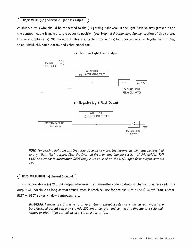
As shipped, this wire should be connected to the (+) parking light wire. If the light flash polarity jumper inside
the control module is moved to the opposite position (see Internal Programming Jumper section of this guide),
this wire supplies a (-) 200 mA output. This is suitable for driving (-) light control wires in Toyota, Lexus, BMW,
some Mitsubishi, some Mazda, and other model cars.
((++)) PPoossiittiivvee LLiigghhtt FFllaasshh OOuuttppuutt
((--)) NNeeggaattiivvee LLiigghhtt FFllaasshh OOuuttppuutt
NNOOTTEE:: For parking light circuits that draw 10 amps or more, the internal jumper must be switchedto a (-) light flash output. (See the Internal Programming Jumper section of this guide.) PP//NN88661177 or a standard automotive SPDT relay must be used on the H1/2 light flash output harnesswire.
This wire provides a (-) 200 mA output whenever the transmitter code controlling Channel 3 is received. This
output will continue as long as that transmission is received. Use for options such as 555511TT Valet® Start system,
552299T or 553300TT power window controllers, etc.
IIMMPPOORRTTAANNTT!! Never use this wire to drive anything except a relay or a low-current input! Thetransistorized output can only provide 200 mA of current, and connecting directly to a solenoid,motor, or other high-current device will cause it to fail.
HH11//33 WWHHIITTEE//BBLLUUEE ((--)) cchhaannnneell 33 oouuttppuutt
HH11//22 WWHHIITTEE ((++//--)) sseelleeccttaabbllee lliigghhtt ffllaasshh oouuttppuutt

© 2004 Directed Electronics, Inc. Vista, CA 55
Connect the H1/4 BLACK/WHITE wire to an optional relay for interior light illumination (pp//nn 88661177 or standard
automotive SPDT relay).
IIMMPPOORRTTAANNTT!! This output is only intended to drive a relay. It cannot be connected directly to the domelight circuit, as the output is not able to support the current draw of one or more light bulbs.
Most vehicles use negative door trigger circuits. Connect the green wire to a wire which shows ground when any
door is opened. In vehicles with factory delays on the domelight circuit, there is usually a wire that is unaffected
by the delay circuitry. This wire will report Zone 3.
This wire will respond to a negative input with an instant trigger. Inputs shorter than 0.8 seconds will trigger
the Warn Away response, while triggers longer than 0.8 seconds will instantly trigger the full alarm cycle. This
wire is ideal for hood and trunk pins and will report on Zone 1. This wire can also be used with Directed
Electronics 506T Glass Breakage Sensor, as well as other Directed Electronics single stage sensors.
The H1/6 BLUE multiplex trigger wire can be used to shunt sensors during operation, using the auxiliary chan-
nels. When any of the auxiliary channels are transmitted, the H1/6 BLUE wire monitors for a ground. If ground
HH11//66 BBLLUUEE ((--)) mmuullttiipplleexx ttrriiggggeerr iinnppuutt,, zzoonnee 11
HH11//55 GGRREEEENN ((--)) ddoooorr ttrriiggggeerr iinnppuutt,, zzoonnee 33
HH11//44 BBLLAACCKK//WWHHIITTEE ((--)) iinntteerriioorr lliigghhtt iilllluummiinnaattiioonn oouuttppuutt

66 © 2004 Directed Electronics, Inc. Vista, CA
is detected within 5 seconds of transmission, the sensors and the multiplex trigger input on the BLUE wire will
be shunted until 5 seconds after the ground is removed. This allows the customer to access the trunk, remote
start the vehicle, or roll the windows down without first disarming the alarm. (See Bypassing Sensor Inputs
section of this guide.)
This wire is used in vehicles that have a positive (+) switched dome light circuit. Connect the violet wire
to a wire that shows (+)12V when any door is opened, and ground when the door is closed. This wire will report
Zone 3.
Remove any paint and connect this wire to bare metal, preferably with a factory bolt rather than your own screw.
(Screws tend to either strip or loosen with time.) We recommend grounding all your components, including the
siren, to the same point in the vehicle. See the following diagram.
Connect this wire to an ignition source. This input must show (+)12V with the key in run position and during
cranking. Make sure that this wire cannot be shorted to the chassis at any point. This wire will report Zone 5.
HH11//88 BBLLAACCKK ((--)) cchhaassssiiss ggrroouunndd ccoonnnneeccttiioonn
HH11//77 VVIIOOLLEETT ((++)) ddoooorr ttrriiggggeerr iinnppuutt,, zzoonnee 33
© 2004 Directed Electronics, Inc. Vista, CA 77
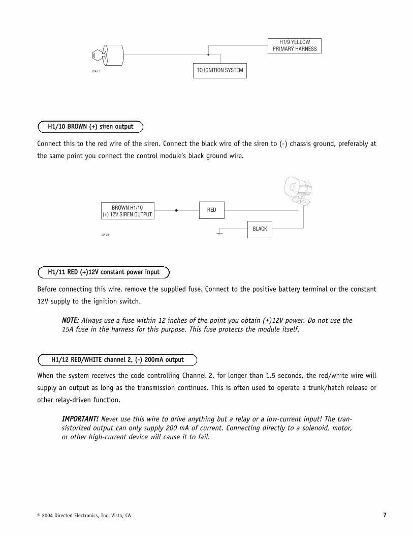
Connect this to the red wire of the siren. Connect the black wire of the siren to (-) chassis ground, preferably at
the same point you connect the control module’s black ground wire.
Before connecting this wire, remove the supplied fuse. Connect to the positive battery terminal or the constant
12V supply to the ignition switch.
NNOOTTEE:: Always use a fuse within 12 inches of the point you obtain (+)12V power. Do not use the15A fuse in the harness for this purpose. This fuse protects the module itself.
When the system receives the code controlling Channel 2, for longer than 1.5 seconds, the red/white wire will
supply an output as long as the transmission continues. This is often used to operate a trunk/hatch release or
other relay-driven function.
IIMMPPOORRTTAANNTT!! Never use this wire to drive anything but a relay or a low-current input! The tran-sistorized output can only supply 200 mA of current. Connecting directly to a solenoid, motor,or other high-current device will cause it to fail.
HH11//1122 RREEDD//WWHHIITTEE cchhaannnneell 22,, ((--)) 220000mmAA oouuttppuutt
HH11//1111 RREEDD ((++))1122VV ccoonnssttaanntt ppoowweerr iinnppuutt
HH11//1100 BBRROOWWNN ((++)) ssiirreenn oouuttppuutt

88 © 2004 Directed Electronics, Inc. Vista, CA
ddoooorr lloocckk hhaarrnneessss ((HH22)) wwiirree ccoonnnneeccttiioonn gguuiiddee______
______
______
This security system can control two common power door lock types without any additional parts! With
certain vehicles, or if an actuator is to be installed, either a 445511MM Door Lock Relay Satellite or two relays will
be required.
This security system can control Type A door locks directly, with no additional parts. The switch will have three
wires on it, and one will test (+)12V constantly. The others will alternately pulse (+)12V when the switch is
pressed to the lock or unlock position.
If you cannot get to the switch, and you find a set of wires that pulse (+)12V alternately on lock and unlock,
you must take care to ensure that it is not a Type C direct-wire system.
IIMMPPOORRTTAANNTT!! If you mistake a Type C direct-wired system for a Type A positive-pulse system, themodule will be damaged!
HHeerree iiss aa tteesstt:: CCuutt tthhee wwiirree wwhhiicchh ppuullsseess ((++))1122VV oonn lloocckk,, aanndd tthheenn ooppeerraattee tthhee sswwiittcchh ttoo uunnlloocckk..
■ If all doors unlock, the vehicle uses a Type A system.
■ If you lose all door lock operation in both directions, you are operating the master switch in a Type C system.
■ If one or more, but not all, motors stop operating, you have cut a wire leading directly to one or more motors.
ttyyppee AA:: ppoossiittiivvee ((++)) 1122VV ppuullsseess ffrroomm tthhee sswwiittcchh ttoo tthhee ffaaccttoorryy rreellaayyss
BBLLUUEE ((++)) LLOOCCKK,, ((--)) UUNNLLOOCCKK OOUUTTPPUUTT
OOPPEENN UUNNLLEESSSS UUSSIINNGG 445511MM
GGRREEEENN ((--)) LLOOCCKK,, ((++)) UUNNLLOOCCKK OOUUTTPPUUTTHH22//11
HH22//22
HH22//33

© 2004 Directed Electronics, Inc. Vista, CA 99
Reconnect the wire and look for another wire.
Many domestically-made GM vehicles use Type A locks. However, many more GM vehicles are Type C than in pre-
vious years. The full-size pickups (1989-later), many of the S10 Blazers, the Corvette, '95 Cavalier/Sunfire 1993
and newer, Camaro/Firebird all use Type C door locks, and cannot be controlled without a 451M! Almost all domes-
tically-built Fords are Type C. Ford builds almost no Type A systems. Chrysler builds both Type A and Type C, so
test carefully.
IIMMPPOORRTTAANNTT!! Remember that the functions of these wires reverse between Type A and Type B!

1100 © 2004 Directed Electronics, Inc. Vista, CA
This system is common in many Toyota, Nissan, Honda, and Saturn models, as well as Fords with remote-con-
trolled door lock/unlock (some other Fords also use Type B).
The switch will have three wires on it, and one wire will test ground all the time. One wire will pulse (-) when
the switch locks the doors, and the other wire will pulse (-) when the switch unlocks the doors. This type of
system is difficult to mistake for any other type.
IIMMPPOORRTTAANNTT!! Remember that the functions of these wires reverse between Type A and Type B!
ttyyppee BB:: nneeggaattiivvee ((--)) ppuullsseess ffrroomm tthhee sswwiittcchh ttoo tthhee ffaaccttoorryy rreellaayyss

© 2004 Directed Electronics, Inc. Vista, CA 1111
Interfacing with a reversing polarity system requires either two relays or one 445511MM (not included).
It is critical to identify the proper wires and locate the master switch to interface properly. Locate wires that
show voltage on lock and unlock. Cut one of the suspect wires and check operation of the locks from both
switches. If one switch loses operation in both directions and the other switch operates in one direction only,
you have located one of the target wires. The switch that lost all operation is the master switch. If one switch
works both directions and the other switch works only one direction, you have a Type A system. If both switches
still operate, but one or more doors have stopped responding entirely, you have cut a motor lead. Reconnect it
and continue to test for another wire. Once both wires have been located and the master switch identified, cut
both wires and interface as shown below.
IIMMPPOORRTTAANNTT!! If these are not connected properly, you will send (+) 12 volts directly to (-)ground, possibly damaging the alarm or the factory switch.
ttyyppee CC:: rreevveerrssiinngg ppoollaarriittyy

1122 © 2004 Directed Electronics, Inc. Vista, CA
In order for this system to control one or more after-market actuators, a 445511MM or two relays (optional) are
needed.
Vehicles without factory power door locks require the installation of one actuator per door. This requires
mounting the door lock actuator inside the door. Other vehicles may only require one actuator installed in the
driver's door if all door locks are operated when the driver's lock is used. This type of installation is required to
operate factory lock systems in Volvo (except 850), SAAB, and most Mazda, Isuzu and Subaru models. The fuse
used on 12-volt inputs should be 7.5A per motor installed in the vehicle.
ttyyppee DD:: aafftteerr--mmaarrkkeett aaccttuuaattoorrss

© 2004 Directed Electronics, Inc. Vista, CA 1133
Door locks are controlled by an electrically activated vacuum pump. Some Mercedes and Audi models use a Type
D system. Test by locking doors from the passenger key cylinder. If all the doors lock, the vehicle's door lock
system can be controlled with just two relays (optional). The control wire can be found in either kick panel and
will show (+)12V when doors are unlocked and (-) ground when doors are locked.
To interface, see diagram below. The system must be programmed for 3.5 second door lock pulses. (See
Operating Settings Remote Control Code Learning section of this guide.)
ttyyppee EE:: mmeerrcceeddeess--bbeennzz aanndd aauuddii ((11998855 aanndd nneewweerr))
1144 © 2004 Directed Electronics, Inc. Vista, CA
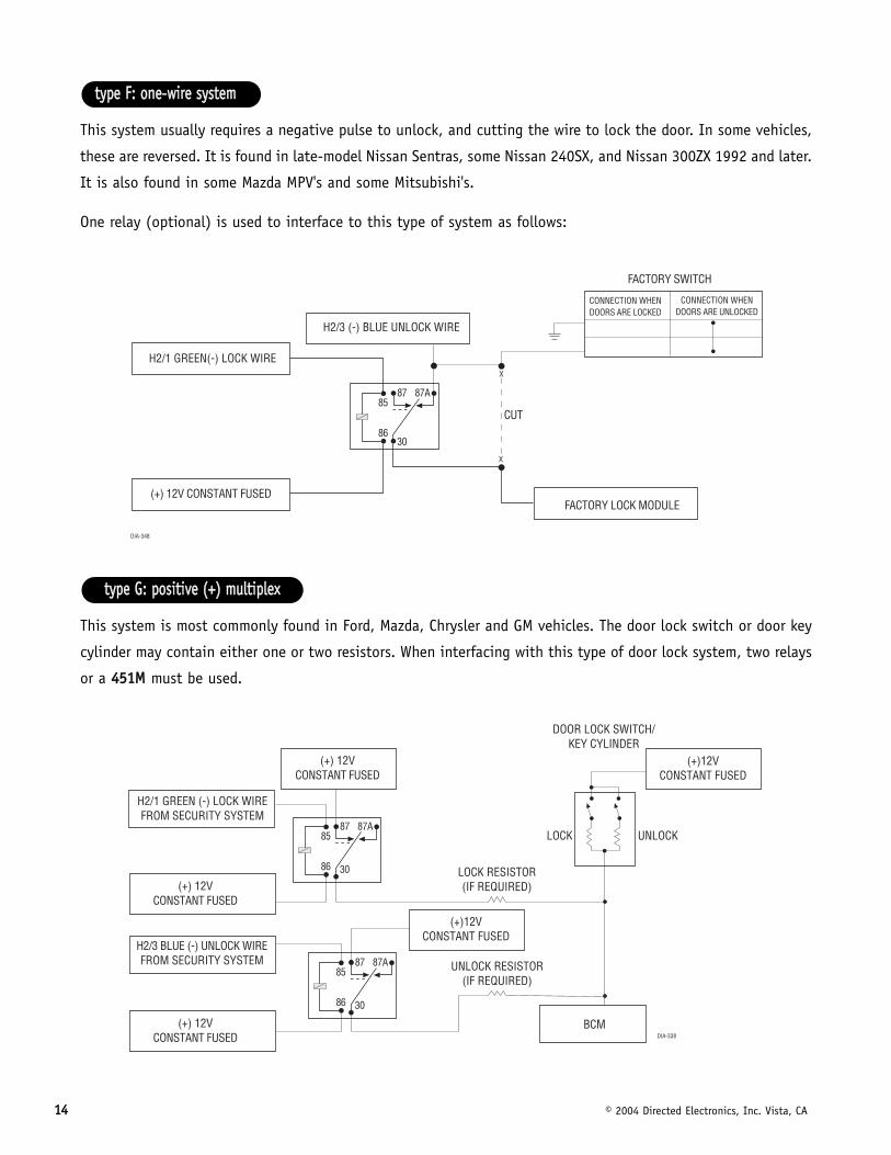
This system usually requires a negative pulse to unlock, and cutting the wire to lock the door. In some vehicles,
these are reversed. It is found in late-model Nissan Sentras, some Nissan 240SX, and Nissan 300ZX 1992 and later.
It is also found in some Mazda MPV's and some Mitsubishi's.
One relay (optional) is used to interface to this type of system as follows:
This system is most commonly found in Ford, Mazda, Chrysler and GM vehicles. The door lock switch or door key
cylinder may contain either one or two resistors. When interfacing with this type of door lock system, two relays
or a 445511MM must be used.
ttyyppee GG:: ppoossiittiivvee ((++)) mmuullttiipplleexx
ttyyppee FF:: oonnee--wwiirree ssyysstteemm

© 2004 Directed Electronics, Inc. Vista, CA 1155
If one resistor is used in the door lock switch/key cylinder, the wire will pulse (+)12V in one direction and less
than (+)12V when operated in the opposite direction.
If two resistors are used in the factory door lock switch/key cylinder, the switch/key cylinder will read less than
(+)12V in both directions.
To determine the resistor values, the door lock switch/key cylinder must be isolated from the factory door lock
system. For all testing, use a calibrated digital multimeter that is set to ohms.
1. Cut the output wire from the door lock switch/key cylinder in half.
2. Test with the meter from the switch side of the cut door lock switch/key cylinder wire to a reliable constant
(+)12V source. Some good constant (+)12V references are the power input source to the door lock switch/key
cylinder, the ignition switch power wire, or the (+) terminal of the battery.
3. Operate the door lock switch/key cylinder in both directions to determine the resistor values. If the multi-
meter displays zero resistance in one direction, no resistor is needed for that direction.
4. Once the resistor value(s) is determined, refer to the wiring diagram for proper wiring.
ddeetteerrmmiinniinngg tthhee pprrooppeerr rreessiissttoorr vvaalluueess
ttwwoo--rreessiissttoorr ttyyppee
ssiinnggllee--rreessiissttoorr ttyyppee

1166 © 2004 Directed Electronics, Inc. Vista, CA
The system is most commonly found in Ford, Mazda, Chrysler and GM vehicles. The door lock switch or door key
cylinder may contain either one or two resistors. When interfacing with this type of door lock system, two relays
or a 445511MM must be used.
If one resistor is used in the door lock switch/key cylinder, the wire will pulse ground in one direction and resis-
tance to ground when operated in the opposite direction.
If two resistors are used in the factory door lock switch/key cylinder, the door lock switch/key cylinder will read
resistance to ground in both directions.
To determine the resistor values, the door lock switch/key cylinder must be isolated from the factory door lock
system. For all testing, use a calibrated digital multimeter that is set to ohms.
1. Cut the output wire from the door lock switch/key cylinder in half.
2. Test with the meter from the switch side of the cut door lock switch/key cylinder wire to a reliable ground
source. Some good ground references are the ground input source to the door lock switch/key cylinder or the
battery ground.
3. Operate the door lock switch/key cylinder in both directions to determine the resistor values. If the multi-
meter displays zero resistance in one direction, no resistor is needed for that direction.
4. Once the resistor value(s) is determined, refer to the wiring diagram for proper wiring.
ddeetteerrmmiinniinngg tthhee pprrooppeerr rreessiissttoorr vvaalluueess
ttwwoo--rreessiissttoorr ttyyppee
ssiinnggllee--rreessiissttoorr ttyyppee
ttyyppee HH:: nneeggaattiivvee ((--)) mmuullttiipplleexx

© 2004 Directed Electronics, Inc. Vista, CA 1177
ssttaarrtteerr iinntteerrrruupptt hhaarrnneessss ((HH33)) wwiirree ccoonnnneeccttiioonn gguuiiddee______
______
Use one of these wire as a starter interrupt input and the other as a starter interrupt output wire
NNOOTTEE:: These two black wires are interchangeable.
pplluugg--iinn LLEEDD aanndd vvaalleett//pprrooggrraamm sswwiittcchhThe LED and the Valet/Program switch both plug into the control module. The LED system status indicator plugs
into the white two-pin port, while the Valet®/Program switch should be plugged into the blue two-pin port. The
status LED and Valet®/Program switch each fit into 9/32-inch holes.
LLEEDD SSyysstteemm SSttaattuuss IInnddiiccaattoorr VVaalleett®®//PPrrooggrraamm SSwwiittcchh
������
HH33//11 aanndd HH33//22 BBLLAACCKK ssttaarrtteerr iinntteerrrruupptt wwiirreess
BBLLAACCKK SSTTAARRTTEERR IINNTTEERRRRUUPPTT OOUUTTPPUUTT
BBLLAACCKK SSTTAARRTTEERR IINNTTEERRRRUUPPTT IINNPPUUTTHH33//11
HH33//22

1188 © 2004 Directed Electronics, Inc. Vista, CA
iinntteerrnnaall pprrooggrraammmmiinngg jjuummppeerr
This jumper is used to determine the light flash output. In the (+) position, the on-board relay is enabled and
the unit will output (+)12V on the H1/2 WHITE wire. In the (-) position, the on-board relay is disabled. The H1/2
WHITE wire will supply a (-) 200 mA output suitable for driving factory parking light relays. To access the jumper,
open the control module.
NNOOTTEE:: For parking light circuits that draw 10 amps or more, the internal jumper must be switchedto a (-) light flash output. PP//NN 88661177 or a standard automotive SPDT relay must be used on theH1/2 light flash output harness wire.
oonn--bbooaarrdd dduuaall ssttaaggee zzoonnee 22 iimmppaacctt sseennssoorr
There is a dual-stage impact sensor inside the control unit. Adjustments are made via the rotary control as indi-
cated above. Since the impact sensor does not work well when mounted firmly to metal, we recommend against
lliigghhtt ffllaasshh jjuummppeerr
���������� �
��������������
����������� ������ ����������� ��������������

© 2004 Directed Electronics, Inc. Vista, CA 1199
screwing down the control module. We recommend mounting the control module to a large wiring loom.
NNOOTTEE:: When adjusting the sensor, it must be mounted in the same location where it will be after the installation is completed. Adjusting the sensor and then relocating the module requires readjustment.
bbyyppaassssiinngg sseennssoorr iinnppuuttssThere are times when you need to temporarily bypass all sensor inputs to the unit, such as when remote start-
ing the vehicle. Anytime an auxiliary channel output is used, all inputs are bypassed for 5 seconds. During the
5 second bypass period, ground can be supplied to the H1/6 BLUE wire without triggering the unit. When the 5
second bypass period ends, if the unit detects ground on the H1/6 BLUE wire, all trigger inputs except the door
trigger input will remain bypassed until 5 seconds after ground is removed from the BLUE wire. This can be done
using the status output of a 551T or 561T remote start unit as shown below:
ttrraannssmmiitttteerr//rreecceeiivveerr rreemmoottee ccoonnttrrooll ccooddee lleeaarrnniinnggThe system comes with two transmitters that have been taught to the receiver. Use the following
transmitter/receiver remote control code learning to add transmitters to the system or to change button assign-
ments if desired.
The Valet®/Program button, plugged into the blue port, is used for programming. There is a basic sequence to
remember whenever programming this unit: Door, Key, Choose, Transmit and Release.

2200 © 2004 Directed Electronics, Inc. Vista, CA
1. OOppeenn aa ddoooorr.. (The GREEN wire, H1/5, or the VIOLET, H1/7 must be connected.)
2. KKeeyy.. Turn the ignition on. (The H1/9 YELLOW switched ignition input must be connected.)
3. SSeelleecctt tthhee rreecceeiivveerr cchhaannnneell.. Press and release the Valet®/Program switch the number of
times necessary to access the desired channel. Once you have selected a channel, press
and HHOOLLDD the Valet®/Program switch once more. The siren will chirp and the LED will blink
the number of times corresponding to the channel that has been accessed.
NNOOTTEE:: If adding a remote, a button must be taught to Channel 1 prior to programming other chan-nels.
4. PPrreessss tthhee ttrraannssmmiitttteerr bbuuttttoonn.. While HHOOLLDDIINNGG the Valet®/Program switch, press the trans-
mitter button that you wish to assign to that channel. The unit will chirp indicating
successful programming. You cannot teach a transmitter button to the system more than once.
NNOOTTEE:: For Channel 7, press Button I (see Transmitter Configuration section of this guide) toprogram the Auto-learn Standard Configuration on a three-button transmitter.
CCHHAANNNNEELL PPRREESSSS AANNDD RREELLEEAASSEE NNUUMMBBEERR TTHHEE VVAALLEETT//PPRROOGGRRAAMM SSWWIITTCCHH TTOO PPRROOGGRRAAMM FFUUNNCCTTIIOONN
1 One Time Arm/Disarm/Panic
2 Two Times Channel 2
3 Three Times Channel 3
4 Four Times Arm Only
5 Five Times Disarm Only
6 Six Times Panic Only
7 Seven Times Auto-learn* for 3-button transmitters
8 Eight Times Delete all transmitters**
**NNOOTTEE:: The Auto-learn function cannot be used to program an optional four-button trans-mitter; the channels must be taught to the transmitter individually. See TransmitterConfiguration section of this guide for a description of Auto-learn transmitter programming.
****NNOOTTEE:: If any button from a known transmitter is programmed to Channel 8, all transmit-ters will be erased from memory and will revert to the default feature settings. (See FeaturesMenu section of this guide.) This is useful in cases where one of the customer's transmittersis lost or stolen. Channel 8 will erase any lost or stolen transmitters from the system'smemory and can also be used to start from scratch if the transmitter buttons were pro-grammed incorrectly.
© 2004 Directed Electronics, Inc. Vista, CA 2211
5. RReelleeaassee.. Once the code is learned, the Valet®/Program button can be released.
You can advance from one channel to another by releasing the Valet® /Program button and tapping it to advance
channels and then HHOOLLDDIINNGG it. For example, if you want to program Channel Three after programming Channel
One, release the Valet®/Program button. Press it twice and release it to advance to Channel Three. Then press it once
more and HHOOLLDD it. The siren will chirp three times to confirm it is ready to receive the code from the transmitter.
CCooddee LLeeaarrnniinngg wwiillll bbee eexxiitteedd iiff::
■ Ignition is turned off.
■ Door is closed.
■ Valet®/Program button is pressed too many times.
■ More than 15 seconds elapses between steps.
One long chirp indicates that Code Learning has been exited.
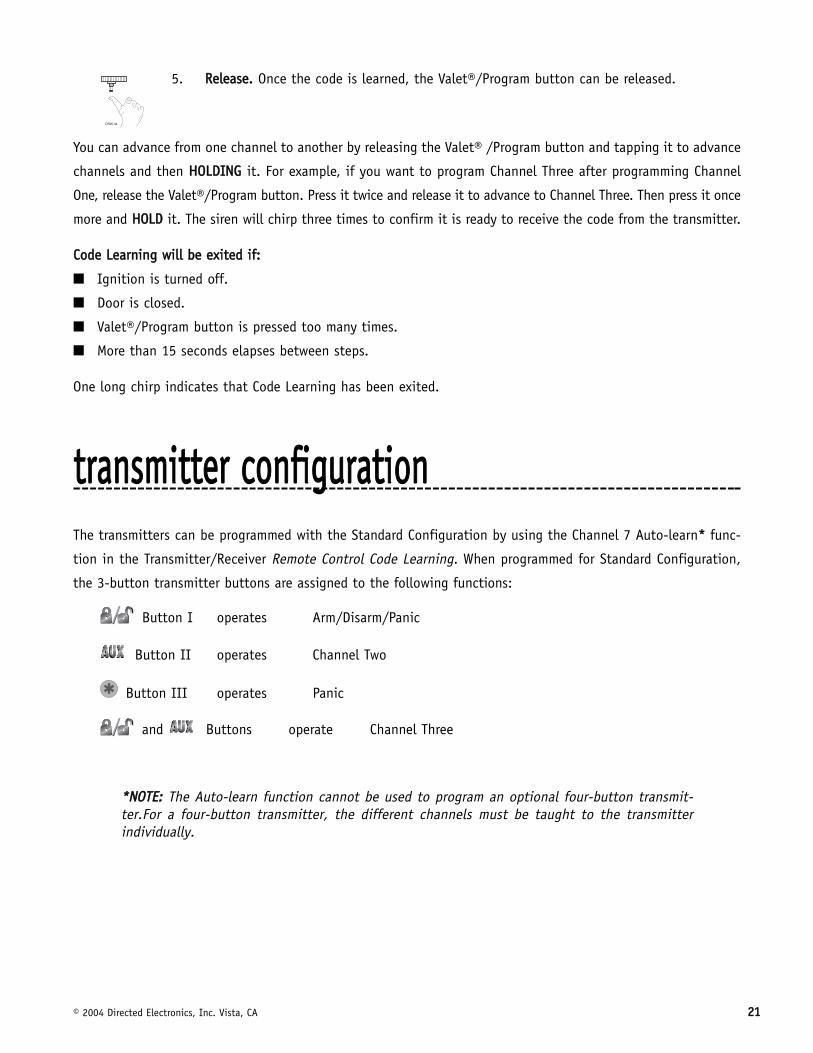
ttrraannssmmiitttteerr ccoonnffiigguurraattiioonnThe transmitters can be programmed with the Standard Configuration by using the Channel 7 Auto-learn** func-
tion in the Transmitter/Receiver Remote Control Code Learning. When programmed for Standard Configuration,
the 3-button transmitter buttons are assigned to the following functions:
Button I operates Arm/Disarm/Panic
Button II operates Channel Two
Button III operates Panic
and Buttons operate Channel Three
**NNOOTTEE:: The Auto-learn function cannot be used to program an optional four-button transmit-ter.For a four-button transmitter, the different channels must be taught to the transmitterindividually.

2222 © 2004 Directed Electronics, Inc. Vista, CA
ooppeerraattiinngg sseettttiinnggss rreemmoottee ccoonnttrrooll ccooddee lleeaarrnniinnggMany of the operating settings of this unit are programmable. They can be changed whenever necessary through
Operating Settings Remote Control Code Learning. The Valet®/Program push-button switch, plugged into the blue
port, is used together with a programmed transmitter to change the settings.
The operating settings dictate how the unit operates. It is possible to access and change any of the feature set-
tings using the Valet®/Program switch.
TToo eenntteerr OOppeerraattiinngg SSeettttiinnggss CCooddee LLeeaarrnniinngg::
1. OOppeenn aa ddoooorr.. ((The GREEN wire, H1/5, or the VIOLET, H1/7 must be connected.)
2. IIggnniittiioonn.. Turn the ignition on, then back off. (The H1/9 YELLOW switched ignition input
must be connected.)
2. CChhoooossee.. Within 10 seconds, press and release the Valet®/Program switch the number of
times corresponding to the feature number you want to program (see the Features Menu
section of this guide). The LED ON settings listed in the Features Menu table are the factory
default settings.
Once the Valet/Program switch has been pressed and released the number of times corre-
sponding to the feature you wish to program, press it once more and HHOOLLDD it. After a
second, the LED will flash to indicate which feature you have accessed. For example, groups
of five flashes would indicate access to Feature 5. The siren will also chirp five times.
4. TTrraannssmmiitt.. While HHOOLLDDIINNGG the Valet®/Program switch, you can select the desired feature
settings using the remote transmitter. As shipped, the unit is configured to the default LED
ON settings. Pressing Button I while HHOOLLDDIINNGG down the Valet/Program switch will program
the feature to the LED ON settings. The siren will chirp once to indicate the one-chirp
setting has been selected. Pressing Button II while HHOOLLDDIINNGG down the Valet/Program
switch will change the setting to the LED OFF setting. The siren will chirp twice indicating
that the LED OFF setting has been selected.
© 2004 Directed Electronics, Inc. Vista, CA 2233
5. RReelleeaassee.. Release the Valet®/Program switch.
TToo aacccceessss aannootthheerr ffeeaattuurree::
You can advance from feature to feature by pressing and releasing the Valet®/Program switch the number of times
necessary to get from the feature you just programmed to the feature you wish to access. For example, if you
just programmed Feature 1 and you want to program Feature 2:
1. Release the Valet®/Program switch.
2. Press and release the Valet/Program switch once to advance from Feature 1 to Feature 2.
3. Press the Valet®/Program switch once more and HHOOLLDD it.
4. The siren will chirp two times to confirm that you have accessed Feature 2.
TToo eexxiitt tthhee CCooddee LLeeaarrnniinngg,, ddoo oonnee ooff tthhee ffoolllloowwiinngg::
■ Close the open door.
■ Turn the ignition on.
■ No activity for longer than 15 seconds.
■ Press the Valet®/Program switch too many times.
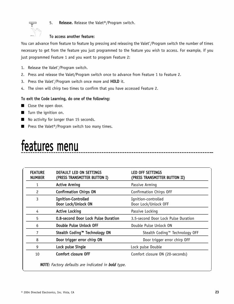
ffeeaattuurreess mmeennuu
FFEEAATTUURREE DDEEFFAAUULLTT LLEEDD OONN SSEETTTTIINNGGSS LLEEDD OOFFFF SSEETTTTIINNGGSSNNUUMMBBEERR ((PPRREESSSS TTRRAANNSSMMIITTTTEERR BBUUTTTTOONN II)) ((PPRREESSSS TTRRAANNSSMMIITTTTEERR BBUUTTTTOONN IIII))
1 AAccttiivvee AArrmmiinngg Passive Arming
2 CCoonnffiirrmmaattiioonn CChhiirrppss OONN Confirmation Chirps OFF
3 IIggnniittiioonn--CCoonnttrroolllleedd Ignition-controlled DDoooorr LLoocckk//UUnnlloocckk OONN Door Lock/Unlock OFF
4 AAccttiivvee LLoocckkiinngg Passive Locking
5 00..88--sseeccoonndd DDoooorr LLoocckk PPuullssee DDuurraattiioonn 3.5-second Door Lock Pulse Duration
6 DDoouubbllee PPuullssee UUnnlloocckk OOFFFF Double Pulse Unlock ON
7 SStteeaalltthh CCooddiinngg™™ TTeecchhnnoollooggyy OONN Stealth Coding™ Technology OFF
8 DDoooorr ttrriiggggeerr eerrrroorr cchhiirrpp OONN Door trigger error chirp OFF
9 LLoocckk ppuullssee SSiinnggllee Lock pulse Double
10 CCoommffoorrtt cclloossuurree OOFFFF Comfort closure ON (20-seconds)
NNOOTTEE:: Factory defaults are indicated in bboolldd type.

2244 © 2004 Directed Electronics, Inc. Vista, CA
ffeeaattuurree ddeessccrriippttiioonnss11 AACCTTIIVVEE//PPAASSSSIIVVEE AARRMMIINNGG:: When active arming is selected, the system will only arm when the transmitter is
used. When set to passive, the system will arm automatically 30 seconds after the last door is closed. Passive
arming is indicated by the rapid flashing of the LED when the last protected entry point is closed.
22 CCOONNFFIIRRMMAATTIIOONN CCHHIIRRPPSS OONN//OOFFFF:: This feature controls the chirps that confirm the arming and disarming of the
system.
33 IIGGNNIITTIIOONN--CCOONNTTRROOLLLLEEDD DDOOOORR LLOOCCKK//UUNNLLOOCCKK OONN//OOFFFF:: When turned on, the doors will lock three seconds after
the ignition is turned on and unlock when the ignition is turned off. If the ignition key is turned on while the
vehicle door(s) are open, the door(s) will not lock.
44 AACCTTIIVVEE//PPAASSSSIIVVEE LLOOCCKKIINNGG:: If passive arming is selected in Feature 1, then the system can be programmed to
either lock the doors when passive arming occurs, or only lock the doors when the system is armed with the
transmitter. Active locking means the system will not lock the doors when it passively arms. Passive locking
means that the system will lock the doors when it passively arms.
55 DDOOOORR LLOOCCKK PPUULLSSEE DDUURRAATTIIOONN:: Some European vehicles, such as Mercedes-Benz and Audi, require longer lock
and unlock pulses to operate the vacuum pump. Programming the system to provide 3.5 second pulses will
accommodate door lock interface in these vehicles. The default setting is 0.8 second door lock pulses. See
Mercedes-Benz and Audi - 1985 and Newer (Type E Door Locks section) diagram.
66 DDOOUUBBLLEE PPUULLSSEE UUNNLLOOCCKK OOFFFF//OONN:: Some vehicles require two pulses on a single wire to unlock the doors. When
the double pulse unlock feature is turned on, the H2/3 BLUE wire will supply two negative pulses instead of a
single pulse. This makes it possible to directly interface with double pulse vehicles without any extra parts.
77 SSTTEEAALLTTHH CCOODDIINNGG™™ TTEECCHHNNOOLLOOGGYY OONN//OOFFFF:: This system features Stealth Coding™ Technology as an option. Stealth
Coding™ Technology is a feature that uses a mathematical formula to change the system’s code each time the
transmitter and receiver communicate. This makes the group of bits or "word" from the transmitter very long.
The longer the word is, the easier it is to block its transmission to the unit. Disabling the Stealth Coding™
Technology feature lets the receiver ignore the Stealth Coding™ Technology part of the transmitted word. As a
result, the unit may have better range with Stealth Coding™ Technology off.
88 DDOOOORR SSEENNSSOORR BBYYPPAASSSS CCHHIIRRPP OONN//OOFFFF:: This feature controls the error chirp that is generated if the system is
armed with the door trigger active. This is useful in vehicles that have a long dome light delay after the door
has been closed. If the system is armed before the dome light has turned off, the security system will generate
the door trigger error chirp. If this error chirp is not desired, use this feature to disable the door open error chirp.
If the bypass chirp is turned off, no bypass chirp will be generated, even if a door is accidentally left open.

© 2004 Directed Electronics, Inc. Vista, CA 2255
99 DDoouubbllee PPuullssee LLoocckk.. Selectable 2 pulse door lock output to operate vehicle equipped with factory “deadbolt”.
Will have similar operation to that of the Double Pulse Unlock feature, but will perform the functions on the Lock
wire as opposed to the Unlock wire
1100 CCoommffoorrtt cclloossuurree ffeeaattuurree:: This feature is designed to integrate with vehicles that can close the power windows
and sunroof by holding the key in the driver door lock position, and will operate on both single input systems
and two pulses input dead bolt systems.
If programmed on the door lock output will activate the Comfort Close output for 20 seconds. This output will
begin 200mS after the final door lock output has completed regardless of the door lock programming.
If while the 20 second timer is active and closing the windows the user disarms the unit, the Comfort Close
output will immediately cease before the doors unlock.
The alarm system will not monitor the zone inputs for Bypass Notification, Warn away or Full trigger inputs until
after the 20 second timer has completed to avoid any false triggering of the system while the window are in
motion.
nnuuiissaannccee pprreevveennttiioonn cciirrccuuiittrryy™™
NPC™ requires that you change the way you test the system, as NPC™ will bypass an input zone for 60 minutes.
If the system “sees” the same zone trigger three times AND the triggers are spaced less than an hour apart, the
system will bypass that input zone for 60 minutes. If that zone does not attempt to trigger the system during
the 60-minute bypass period, the zone’s monitoring will begin again at the end of the hour. If it does attempt
to trigger while bypassed, the 60-minute bypass starts over again.
Disarming and rearming the system does not reset NPC™. The only way to reset NPC™ is for the 60 minutes to
pass, without a trigger, or for the ignition to be turned on. This allows the system to be repeatedly triggered,
disarmed and rearmed, and still allow NPC™ to bypass a faulty zone.
When disarming the system, 5 chirps indicate NPC is activated. The LED will report the zone that has been
bypassed. (See Table of Zones section of this guide.)

2266 © 2004 Directed Electronics, Inc. Vista, CA
ttaabbllee ooff zzoonneessWhen using the Diagnostic functions, use the Table of Zones to see which input has triggered the system. It is
also helpful in deciding which input to use when connecting optional sensors and switches.
ttrroouubblleesshhoooottiinngg■ DDoooorr iinnppuutt ddooeess nnoott iimmmmeeddiiaatteellyy ttrriiggggeerr ffuullll aallaarrmm.. IInnsstteeaadd,, ffiirrsstt II hheeaarr cchhiirrppss ffoorr 33 sseeccoonnddss::
That's how the progressive two-stage door input works! This is a feature of this system. This is an instant trigger,
remember, since even if the door is instantly re-closed, the progression from chirps to constant siren will con-
tinue.
■ CClloossiinngg tthhee ddoooorr ttrriiggggeerrss tthhee ssyysstteemm,, bbuutt ooppeenniinngg tthhee ddoooorr ddooeess nnoott::
Have you correctly identified the type of door switch system? This often happens when the wrong door input has
been used. (See H1/5 GREEN Door Trigger Input, Primary Harness Wire Connection Guide section of this guide.)
■ SSyysstteemm wwiillll nnoott ppaassssiivveellyy aarrmm uunnttiill iitt iiss rreemmootteellyy aarrmmeedd aanndd tthheenn ddiissaarrmmeedd::
Are the door inputs connected? Is the H1/6 blue wire connected to the door trigger wire in the vehicle? Either
the H1/5 green or the H1/7 violet should be used instead. (See Primary Harness Wire Connection Guide section
of this guide.)
ZZOONNEE NNOO.. TTRRIIGGGGEERR TTYYPPEE IINNPPUUTT DDEESSCCRRIIPPTTIIOONN
1 Multiplexed H1/6 BLUE wire. Connects to optional hood/trunk pins oran optional sensor. Inputs longer than 0.8 seconds will instantly trigger the full alarm sequence and report Zone 1.
2 On-board impact sensor Second-stage of on-board impact sensor (heavy impactsfrom impact sensor).
3 Two-stage, progresses from Door switch circuit. H1/5 GREEN or H1/7 VIOLET.warning to full alarm
5 Two-stage, progresses from Ignition. H1/9 YELLOW.warning to full alarm
NNOOTTEE: The Warn-away response does not report on the LED.

© 2004 Directed Electronics, Inc. Vista, CA 2277
■ DDoooorr iinnppuutt ddooeess nnoott rreessppoonndd wwiitthh tthhee pprrooggrreessssiivvee ttrriiggggeerr,, bbuutt wwiitthh iimmmmeeddiiaattee ffuullll aallaarrmm::
Does the LED indicate that the trigger was caused by the impact sensor? (See Table of Zones section of this
guide.) The impact sensor, if set to extreme sensitivity, may be detecting the door unlatching before the door
switch sends its signal. Reducing the sensitivity can solve this problem.
■ TThhee VVaalleett®®//PPrrooggrraamm sswwiittcchh ddooeess nnoott wwoorrkk::
Is it plugged into the correct socket? (See Plug-In LED and Valet/Program Switch section of this guide.)
■ TThhee LLEEDD ssyysstteemm ssttaattuuss iinnddiiccaattoorr ddooeess nnoott wwoorrkk::
You've probably guessed already, but here goes: is it plugged in? Is the LED plugged into the correct socket?
(See Plug-In LED and Valet/Program Switch section of this guide.)
■ SSttaarrtteerr iinntteerrrruupptt ddooeess nnoott wwoorrkk::
Is the correct wire being interrupted? If the vehicle starts when the starter interrupt is completely disconnected,
the wrong wire has been cut.
Is the yellow H1/9 ignition wire connected to true ignition? This wire must be powered in the run and start
positions in order to work properly.

2288 © 2004 Directed Electronics, Inc. Vista, CA

© 2004 Directed Electronics, Inc. Vista, CA 2299
wwiirriinngg qquuiicckk rreeffeerreennccee gguuiiddee
��
��������� ����
����
������
�����
��������� �
�������
������
���
�������� � ������������������ ������
�� ����������������
���������������
������
�������� ���!�"
���
���#$$�"!
� %��
&�����'���%� ��(
�) �
�*���+$!
� %��*��� ��
, �����-�!�.%%�
�/�������
����$$�"!
���*�
%��
0����%���0�"
%���%���
����$$�"!
1��2
���0��%�%���0����
3����4#
�����
�����5
�%�����0�����
���3����4-
��
5����*6����0�����
���3����4+
7%���
�����5
�%�����0�����
���3����4-
���� ��
, �))%)��������
��2�
&%�����������
���+!
���� ��
,��)�����8
�2���
���*�
%��
����$$�"!�, ������
!�.%%��/�������
����$$�"!
������� ����!
��������� ��������
"���������#��"���$������������
����������
%�#���&�����'����� �
%�#���&������'������������
'�����&�����'����� �
���
���
�()*����� ��
'�����#��#��+���
(�)�
���
����
0"�����&��)��
&��)%�%9%�/
���
&�����
��0���������0����*�
������
���
&�������0���������0����*�
������
������������������� ���#��,���
������-����)
������-���������
.���!��/������
01*'��20'��$���2������
3*'��41*+���21������ �2������
!������
��
��
��
23������"��������'��#*��2������