horizontal wells subsurface contaminants - … horizontal wells subsurface contaminants focus area...
TRANSCRIPT
DOE/EM-0378
Horizontal Wells
Subsurface Contaminants Focus Area
Prepared for
U.S. Department of Energy Office of Environmental Management
Office of Science and Technology
September 1998
DISCLAIMER This report was prepared as an account of work sponsored by an agency of the United StatesGovernment. Neither the United States Government nor any agency thereof, nor any of their employees,makes any warranty, express or implied, or assumes any legal liability or responsibility for the accuracy,completeness, or usefulness of any information, apparatus, product, or process disclosed, or representsthat its use would not infringe privately owned rights. Reference herein to any specific commercialproduct, process, or service by trade name, trademark, manufacturer, or otherwise does not necessarilyconstitute or imply its endorsement, recommendation, or favoring by the United States Government orany agency thereof. The views and opinions of authors expressed herein do not necessarily state orreflect those of the United States Government or any agency thereof.
Horizontal Wells OST Reference # 1927
Subsurface Contaminants Focus Area
Demonstrated at U.S. Department of Energy
Savannah River Site Aiken, South Carolina
Hanford Site Richland, Washington
Sandia National Laboratories and Kirtland Air Force Base
Albuquerque, New Mexico Other Commercial and Government Sites
Purpose of this document Innovative Technology Summary Reports are designed to provide potential users with theinformation they need to quickly determine if a technology would apply to a particularenvironmental management problem. They are also designed for readers who mayrecommend that a technology be considered by prospective users. Each report describes a technology, system, or process that has been developed and testedwith funding from DOE’s Office of Science and Technology (OST). A report presents the fullrange of problems that a technology, system, or process will address and its advantages to theDOE cleanup in terms of system performance, cost, and cleanup effectiveness. Most reportsinclude comparisons to baseline technologies as well as other competing technologies.Information about commercial availability and technology readiness for implementation is alsoincluded. Innovative Technology Summary Reports are intended to provide summaryinformation. References for more detailed information are provided in an appendix. Efforts have been made to provide key data describing the performance, cost, and regulatoryacceptance of the technology. If this information was not available at the time of publication,the omission is noted. All published Innovative Technology Summary Reports are available on the OST Web site at http://em-50.em.doe.gov under “Publications.”
SUMMARY page 1
TECHNOLOGY DESCRIPTION page 4
PERFORMANCE page 7
TECHNOLOGY APPLICABILITY AND ALTERNATIVES page 10
COST page 12
REGULATORY AND POLICY ISSUES page 14
LESSONS LEARNED page 16
APPENDICES
References
Acronyms and Abbreviations
1
2
3
4
5
6
7
A
B
TABLE OF CONTENTS

U. S. Department of Energy 1
SECTION 1
Technology Description
Horizontal environmental wells have been demonstrated and deployed as an enhanced access methodfor treatment of contaminated soils and ground water. Directional drilling methods use specialized bitscoupled with electronic transmitters in the drillhead to locate and steer as the borehole is advanced.Horizontal drilling was originally developed by industry for oil recovery, utility placement, mining, andconstruction. The United States Department of Energy’s (DOE) Office of Science and Technology(EM50) adapted the technology for environmental remediation applications in the late 1980s and early1990s. A user survey for horizontal wells installed in the United States documented over 500 through 1996.Many wells are being installed by small companies that previously conducted directional drilling for theutility industry and as such have not been documented. It is likely that over 1,000 wells currently exist inthe United States. Horizontal wells have been used primarily for ground-water extraction (33 percent),soil vapor extraction (35 percent), air sparging (21 percent), and other methods (11 percent) such ashydraulic control, free product recovery, and bioremediation/bioventing.
Benefits
Horizontal well remediation systems are usually faster, cheaper, and more effective than the baselinetechnology of vertical wells. They provide:
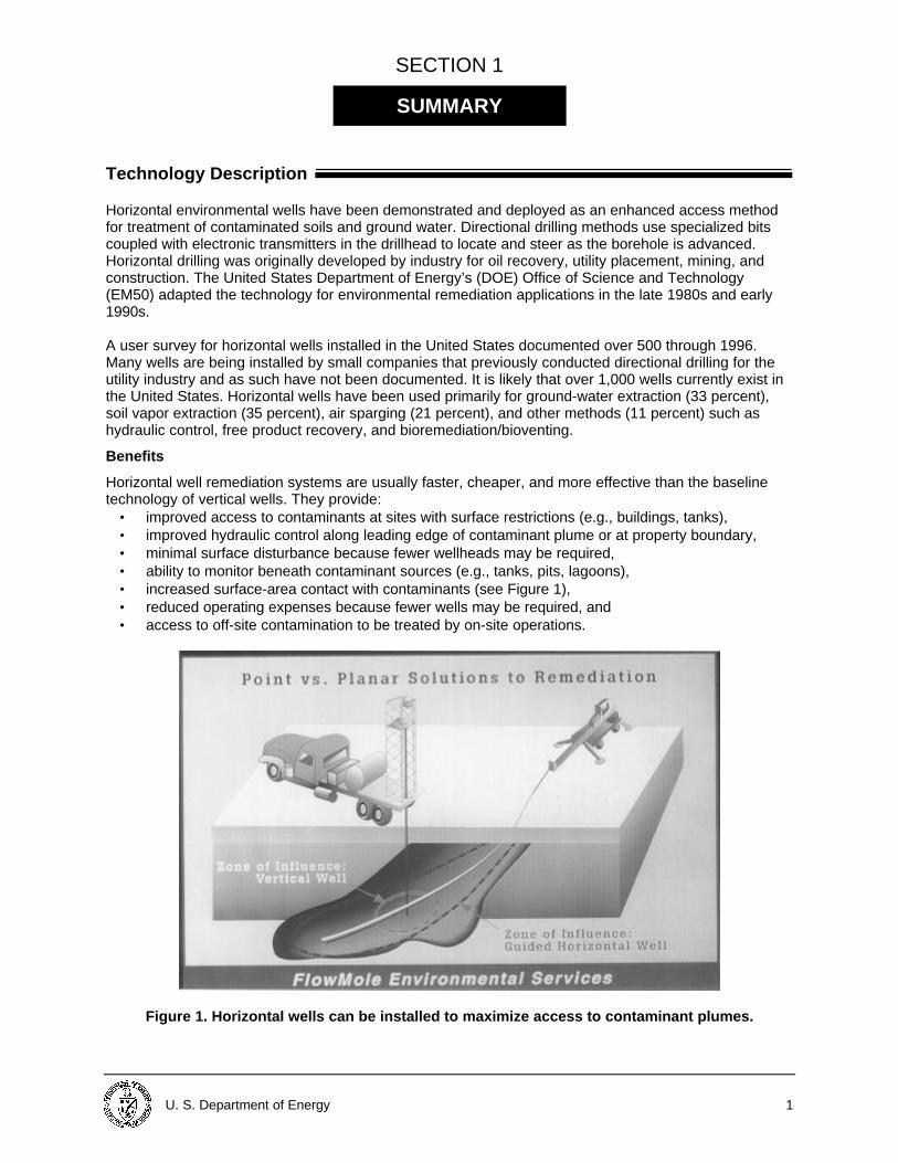
• improved access to contaminants at sites with surface restrictions (e.g., buildings, tanks),• improved hydraulic control along leading edge of contaminant plume or at property boundary,• minimal surface disturbance because fewer wellheads may be required,• ability to monitor beneath contaminant sources (e.g., tanks, pits, lagoons),• increased surface-area contact with contaminants (see Figure 1),• reduced operating expenses because fewer wells may be required, and• access to off-site contamination to be treated by on-site operations.
Figure 1. Horizontal wells can be installed to maximize access to contaminant plumes.
SUMMARY
2 U.S. Department of Energy
Horizontal environmental wells can be used for ground-water or soil-vapor removal for surface treatment;in situ treatment of ground water and soil; hydraulic control of ground water; and monitoring of soil vaporor ground water (e.g., beneath contaminant sources). Horizontal wells can be installed by directional drilling or by trenching and backfilling (if specific siteconditions allow it). Trenching and backfilling requires shallow depths and continuous surface access.Directional drilling can be used to install impermeable or permeable barriers and can be combined withfracturing technology in low permeability sediments. Horizontal drilling concerns include reduced permeability of the geologic formation during well installationcaused by compaction drilling tools or due to introduced drilling fluids (same as for vertical drilling); andpotential for drilling fluids to foul uncontaminated areas, damage equipment, and interrupt utility services,or compromise soil stability beneath pavement and structures. Costs for disposal of contaminatedbackfill and drilling fluids/cuttings must be assessed during technology selection. For operators,experience in directional drilling is a must, and experience in drilling water well and hazardous wastesites is preferred. Horizontal wells have been implemented at DOE’s Savannah River Site (SRS) in Aiken, SC; SandiaNational Laboratories (SNL) and Kirtland Air Force Base (KAFB), Albuquerque, NM; and the HanfordSite, Richland, WA. For a listing of commercial and other governmental implementation sites, see the1996 survey noted above, available on the World Wide Web at http://www.doegjpo.com/ccem/et.htm.
Demonstration Summary
DOE has supported development, demonstration, and applications of horizontal environmental wells asan enhanced access technology from 1988 through 1997:
• at SRS, where four directional drilling technologies were demonstrated. From 1988 through 1993,seven wells were installed and used to demonstrate innovative remediation technologies fortreatment of volatile-organic contaminants (VOCs) in ground water and soils. Four of these wellshave been integrated into the M-Area vapor extraction corrective action system. Two more wellswere installed in 1997 to remediate ground water at the Sanitary Landfill.
• at SNL, where development and demonstration of directional drilling technologies were conductedfrom 1991 through 1995 in cooperation with Charles Machine Works (CMW), a utility directionaldrilling rig manufacturer. Field tests were conducted at SNL, KAFB, SRS, and Hanford.
• at the Portsmouth Gaseous Diffusion Plant (PORTS), where horizontal wells were installed todemonstrate and apply a recirculating ground-water treatment system using an innovative well-screen material, and for hydraulic recovery of ground water for iron-filings treatment.
• at Pinellas, where nine wells were installed for ground-water treatment of VOCs in 1995 through1997. Seven wells were used for in situ air sparging, resulting in clean up of the site to drinkingwater standards and subsequent site closure. Two additional wells were used in conjunction withthree surface trenches to establish a forced vertical gradient for in situ bioremediation.
Key Results
Horizontal wells have been successfully installed at hundreds of sites across the United States andworldwide to treat and manage contaminated ground water and soils. Many of these projects havedemonstrated that horizontal wells save overall remediation costs by cleaning up the site more quicklythan vertical wells and by lowering maintenance and operating costs.
• Regulatory approval requirements for horizontal wells are similar to those for vertical wells. At theDOE Pinellas Plant, horizontal wells successfully remediated vinyl chloride in ground water,resulting in regulatory closure approval (at a site containing initial concentrations of ~40 ppb) afteronly approximately one year of operation.
• Horizontal wells have been shown to be more efficient than vertical wells. For example, at SRS ahorizontal well used for vapor extraction was five times more efficient than a vertical well.Modeling studies have predicted more rapid cleanup (5 years versus 20 years) using horizontalwells as opposed to vertical wells.
U. S. Department of Energy 3
• Directional drilling methods have been successfully modified for environmental applications, undera number of different geologic conditions, from unconsolidated sands, silts, and clays toconsolidated rock at depths ranging from five to over 200 ft.
• The economics of using horizontal wells are enhanced if their application allows operatingbusinesses to remain open while site remediation is occurring (e.g., gas stations and airports). AtJFK Airport in NY, over 25,000 linear ft of horizontal wells were installed beneath runways to keepairport operations on schedule while cleanup operations were under way. At a chemical plant inLouisiana, over 30,000 ln ft of horizontal wells were installed for a pump-and-treat hydraulic controlsystem to operate while plant operations continued.
• Horizontal wells are especially cost effective at low-permeability sites where numerous verticalwells would be required. For example, at Williams Air Force Base in AZ, the deepest horizontalenvironmental wells have been installed; at this site one horizontal well was predicted to replace80 vertical wells. Horizontal environmental wells are also well applied in thin aquifers, inunconfined aquifers, and at sites with vertical fractures.
Commercial Availability
Directional drilling rigs for drilling and installation of horizontal environmental wells are commerciallyavailable from a number of vendors, including Charles Machine Works who partnered with DOE tofurther develop the technology. Directional drilling services are available from a number of drillingcompanies. In addition, there are a number of consultants who specialize in the design and oversight ofhorizontal environmental well installations. A current list of these companies and individuals is availablefrom the Technical Contact listed below.
Contacts
Technical Dawn Kaback Colorado Center for Environmental Management (303) 297-0180, ext. 111e-mail: [email protected] Management Skip Chamberlain DOE EM50, Program Manager, Subsurface Contaminant Focus Area (301) 903-7248e-mail: [email protected] Jim Wright DOE SRS, Lead Office Manager, Subsurface Contaminant Focus Area(803) 725-5608e-mail: [email protected] Other All published Innovative Technology Summary Reports are available on the OST Web site at http://em-50.em.doe.gov under “Publications.” The Technology Management System, also available through theOST Web site, provides information about OST programs, technologies, and problems. The OSTReference # for horizontal wells is 1927.
4 U.S. Department of Energy
SECTION 2
Overall Process Definition
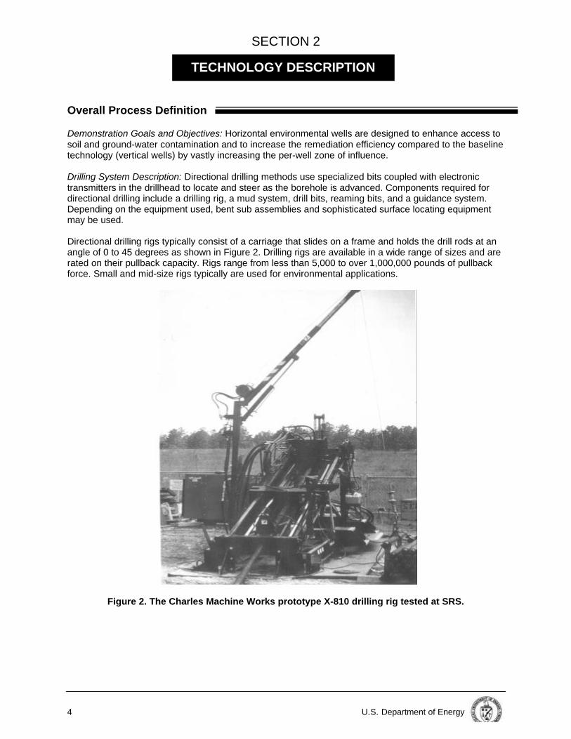
Demonstration Goals and Objectives: Horizontal environmental wells are designed to enhance access tosoil and ground-water contamination and to increase the remediation efficiency compared to the baselinetechnology (vertical wells) by vastly increasing the per-well zone of influence. Drilling System Description: Directional drilling methods use specialized bits coupled with electronictransmitters in the drillhead to locate and steer as the borehole is advanced. Components required fordirectional drilling include a drilling rig, a mud system, drill bits, reaming bits, and a guidance system.Depending on the equipment used, bent sub assemblies and sophisticated surface locating equipmentmay be used. Directional drilling rigs typically consist of a carriage that slides on a frame and holds the drill rods at anangle of 0 to 45 degrees as shown in Figure 2. Drilling rigs are available in a wide range of sizes and arerated on their pullback capacity. Rigs range from less than 5,000 to over 1,000,000 pounds of pullbackforce. Small and mid-size rigs typically are used for environmental applications.
Figure 2. The Charles Machine Works prototype X-810 drilling rig tested at SRS.
TECHNOLOGY DESCRIPTION
U. S. Department of Energy 5
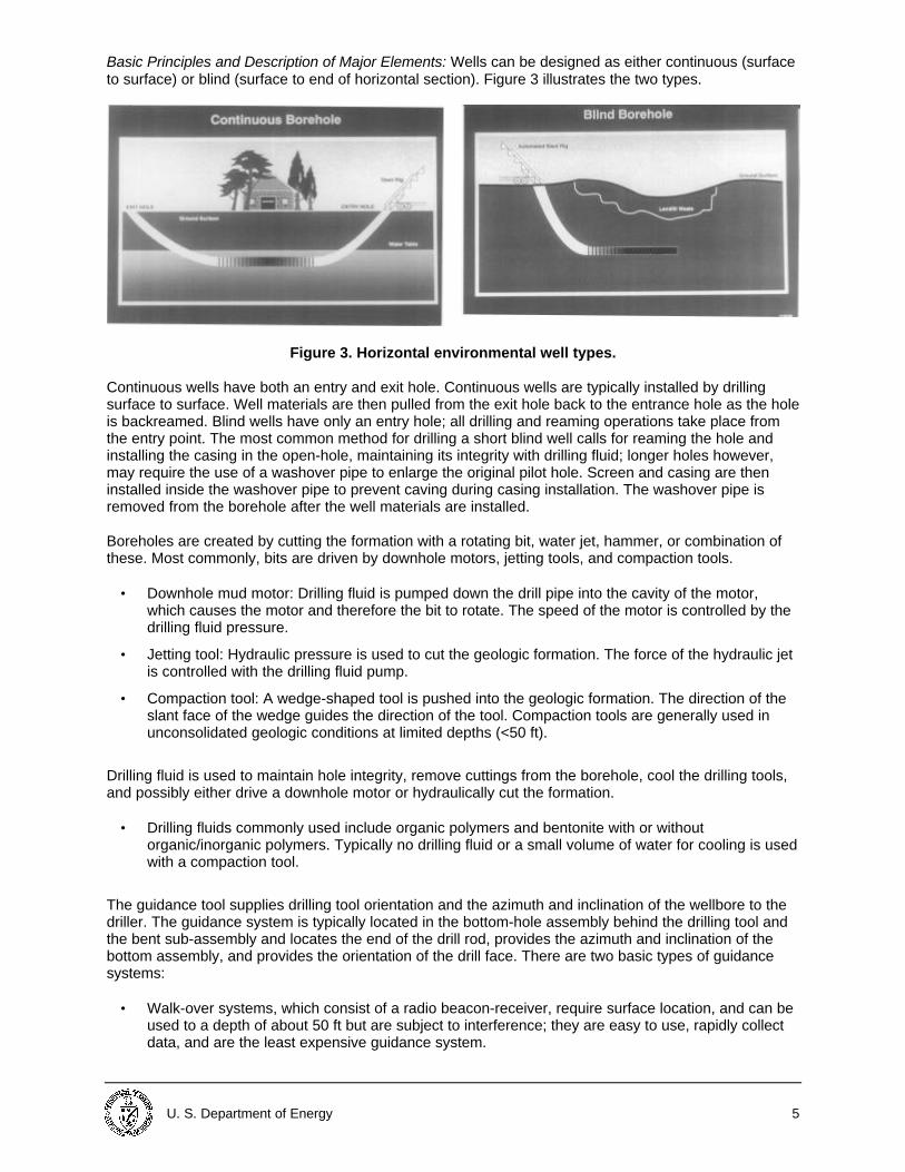
Basic Principles and Description of Major Elements: Wells can be designed as either continuous (surfaceto surface) or blind (surface to end of horizontal section). Figure 3 illustrates the two types.
Figure 3. Horizontal environmental well types. Continuous wells have both an entry and exit hole. Continuous wells are typically installed by drillingsurface to surface. Well materials are then pulled from the exit hole back to the entrance hole as the holeis backreamed. Blind wells have only an entry hole; all drilling and reaming operations take place fromthe entry point. The most common method for drilling a short blind well calls for reaming the hole andinstalling the casing in the open-hole, maintaining its integrity with drilling fluid; longer holes however,may require the use of a washover pipe to enlarge the original pilot hole. Screen and casing are theninstalled inside the washover pipe to prevent caving during casing installation. The washover pipe isremoved from the borehole after the well materials are installed. Boreholes are created by cutting the formation with a rotating bit, water jet, hammer, or combination ofthese. Most commonly, bits are driven by downhole motors, jetting tools, and compaction tools.
• Downhole mud motor: Drilling fluid is pumped down the drill pipe into the cavity of the motor,which causes the motor and therefore the bit to rotate. The speed of the motor is controlled by thedrilling fluid pressure.
• Jetting tool: Hydraulic pressure is used to cut the geologic formation. The force of the hydraulic jetis controlled with the drilling fluid pump.
• Compaction tool: A wedge-shaped tool is pushed into the geologic formation. The direction of theslant face of the wedge guides the direction of the tool. Compaction tools are generally used inunconsolidated geologic conditions at limited depths (<50 ft).
Drilling fluid is used to maintain hole integrity, remove cuttings from the borehole, cool the drilling tools,and possibly either drive a downhole motor or hydraulically cut the formation.
• Drilling fluids commonly used include organic polymers and bentonite with or withoutorganic/inorganic polymers. Typically no drilling fluid or a small volume of water for cooling is usedwith a compaction tool.
The guidance tool supplies drilling tool orientation and the azimuth and inclination of the wellbore to thedriller. The guidance system is typically located in the bottom-hole assembly behind the drilling tool andthe bent sub-assembly and locates the end of the drill rod, provides the azimuth and inclination of thebottom assembly, and provides the orientation of the drill face. There are two basic types of guidancesystems:
• Walk-over systems, which consist of a radio beacon-receiver, require surface location, and can beused to a depth of about 50 ft but are subject to interference; they are easy to use, rapidly collectdata, and are the least expensive guidance system.
6 U.S. Department of Energy
• Steering tool systems, which include either an inertial (gyroscope) system (the most expensivesystem) or a combination magnetometer-accelerometer (the most commonly used system,especially at depths > 40 ft) provide real-time information of greater accuracy at a higher cost thanwalk-over systems. They have built-in memory capacity and no depth limitations.
System Operation
Operational Parameters and Conditions: Operational requirements for directional drilling include onedriller, one guidance technician, and one helper at a minimum. However, additional personnel (typically aproject manager, construction engineer, geologist, health and safety officer, and/or health physicstechnician) are required when drilling at hazardous waste sites. Horizontal well design considerations include geologic and hydrogeologic conditions; contaminantdistribution; drilling methods (rig, fluids, etc.); survey tools; horizontal wellbore specifications (i.e., lengthand target depth of the well, borehole path); composition and design of well materials; and use of the well. Materials and Energy Considerations: Well materials need to be flexible, have adequate tensile andcompressive strength, have strong joints, and be compatible with the use of the well and the chemicalcomposition of the ground water.
• Wells have been constructed using polyvinyl chloride (PVC), high-density polyethylene (HPDE),carbon steel, stainless steel, fiberglass, and porous polyethylene. The costs of these variousmaterials range widely and highly influence the cost for installation of a horizontal well.
• Wells may use pre-packed screen if there is concern about formation infiltration. However, pre-packed screen may add greatly to the cost of the well and may be difficult to install, because ofincreased weight. Pre-packed screen should only be used if necessary at a specific site. Filterfabric is often used over HDPE screen to prevent infiltration of formation material into the screen,because of HDPE’s lower limit on slot size (.020 in).
• According to the 1996 horizontal well survey report, there is a trend toward the use of HPDE as thewell screen material of choice unless there is a concern about the well integrity due to thepresence of aggressive chemicals (in which case, stainless steel is used), depth of installation, orlength of materials to be installed.
Casing pull tests conducted by SNL indicated that selecting the appropriate casing includes consideringloads on the equipment and materials. These loads include pulling the casing; the reamer, if used duringpull back; the drill rig carriage drag; size and rotation of the pull back drill pipe; the casing pulling plugdesign; and bends (i.e., the radius of curvature) or irregularities in the wellbore. Personnel Skills and Training Requirements: Experience in directional drilling is a must, and experiencein drilling water well and hazardous waste sites is preferred. Potential Safety and Environmental Risks and Concerns: Not significant. Please see Section 6.
U. S. Department of Energy 7
SECTION 3
Demonstration Plan
Directional drilling technologies were demonstrated at SRS, SNL, KAFB, and Hanford to test differentsystems under variable site conditions. These demonstrations were conducted under the then Office ofTechnology Development’s SRS Integrated Demonstration: VOCs in Soil and Ground Water at Non-aridSites and the Mixed Waste Landfill Integrated Demonstration at SNL. The Kirtland and Hanforddemonstrations are considered part of the SNL demonstration.
Savannah River Site Demonstration (1988–1993)
Demonstration Site Description: Hydrologic investigations at SRS have shown contamination of theground water with VOCs near the M-Area Settling Basin from the leakage of waste solvents from a tileprocess sewer into the vadose zone. A remedial action program consisting of ground-water pumpingfollowed by above-ground air stripping has been implemented to address ground-water contamination inM-Area. A vapor extraction system has been installed to address the vadose zone contamination. The geology in the M-Area is characterized by 200 ft of alternating units of permeable sands with lowfines and significantly less permeable clayey sand and clay units. The water table is located atapproximately 120 ft below ground surface (bgs). The sand units range from fine-to coarse-grained and are generally moderately sorted with relatively littlesilt and clay. Interbedded with the sands are silty clay or clayey sand units, which exhibit relatively lowpermeabilities. Generally, the clays tend to be thin and discontinuous. The more permeable units wereselected as target zones for the horizontal environmental wells. Demonstration Objectives and Elements: The goal of the SRS demonstration was to test the feasibility ofinstalling horizontal wells in unconsolidated sediments, using directional drilling technology. Fourdistinctly different systems of directional drilling and horizontal well installations were successfullydemonstrated and evaluated at SRS:
• A short-radius petroleum-industry technology was used to install two wells, one at 65 ft bgs andone below the water table at a depth of 150 to 175 ft. The deeper well, which consists of perforatedsteel casing, was used for air injection; the shallower well, of stainless steel screen, for vaporextraction.
• A modified petroleum-industry technology was used to install two horizontal wells with the sameconfiguration as the previous demonstration; wells were constructed of HDPE.
• A mini-rig utility-industry/compactional tool drilling technology was demonstrated by CMW to installa well in a 35 to 40 ft deep clay layer to test the effectiveness of radio-frequency heating enhancedsoil vapor extraction. This well used slotted fiberglass casing.
• A midi-rig utility-industry technology was used to install two wells at a depth of about 100 ft toconduct soil vapor extraction beneath a closed seepage basin used for waste disposal. These wellswere constructed of PVC screen and casing.
Seven wells were successfully installed at depths of 35 to 175 ft, with horizontal screen sections rangingfrom 150 to 400 ft, using the following materials: steel, stainless steel, PVC, HDPE, and fiberglass. Thewells were utilized to demonstrate in situ air stripping, in situ bioremediation, and thermally enhanced soilvapor extraction. Four of the wells were later integrated into the M-Area vapor extraction correctiveaction. Note: Innovative Technology Summary Reports on In Situ Air Stripping Using Horizontal Wells and InSitu Bioremediation Using Horizontal Wells are available online at http://em-50.em.doe.gov.
PERFORMANCE

8 U.S. Department of Energy
Evaluation of the horizontal well installation performance at SRS was based on (1) whether the wellborewas drilled in the proper location with minimum damage to the host formation, (2) whether the wellmaterials were successfully installed in the wellbore, and (3) whether the well could meet the designatedremediation objectives. The SRS demonstrations identified two important factors for consideration during design of horizontalenvironmental wells: (1) trips in and out of the wellbore should be minimized to maintain wellborestability, and (2) well materials should be adequately flexible to negotiate curves. Other lessons learnedadvanced the state of the technology. Of the four technologies demonstrated at SRS, the mini-rig andmidi-rig utility technologies remain in use.
Sandia National Laboratories Demonstration (1991–1995)
Demonstration Site Description: Testing was conducted at several locations as part of the SNLdemonstration. The background and history of the various sites are briefly described below:
• The CMW experimental test range is located at Perry, OK northeast of the main CMWmanufacturing facility. This site is a field with a slight elevation increase from south to north orfrom the selected entry toward the exit end of the test bed.
• The SNL Directional Boring Test Range (DBTR) is a clean site of six acres located in Albuquerque,NM.
• The KAFB RB-11 site was used for radiation effects testing during the 1950s and 60s. Severalshallow open trenches were filled with low level contaminated post test debris.
• The M-Area at SRS is described above. An additional test was performed at the TNX Facility atSRS. This facility is located on a low bluff along the Savannah River, separated from the river by amarsh area.
• The Hanford test site was a clean test area located between Technical Areas 200-E and 200-W.
Testing was conducted at several locations as part of the SNL demonstration. The geology at the varioussites is briefly described:
• The soils in Perry, OK are basically clay to about 14 ft bgs underlain by a 5 ft zone of shale then adeeper zone of more dense clay with some sand and small gravel.
• The geology at SNL is alluvial in origin containing caliche, sands, gravels, cobbles, and bouldersdistributed somewhat randomly, except that some cobbles are concentrated in layers of old riverbeds at least 30 ft bgs.
• The soils at KAFB are the same at SNL.
• The geology in the M-Area at SRS is characterized by 200 ft of alternating units of permeablesands with low fines and significantly less permeable clayey sand and clay units. The target zoneof the horizontal wells was a clay layer.
• The geology at the Hanford test site is composed of glacial till with uncemented sand and multiplelayers of semi-spherical cobbles ranging from baseball to basketball size.
Iterative technology testing and development by SNL resulted in high-quality, cost-effective accessbeneath waste sites while minimizing site impact. Demonstration Objectives and Elements: Goals of the testing and development at SNL were to minimizeenvironmental impact by the boring/drilling/thrusting method; and provide a low-cost but high-qualityalternative to more expensive directional drilling methods for certain geologies. A no-cost industrialpartnership between SNL and CMW (makers of Ditch Witch products) was established to enable testingof several existing types of machinery used in the shallow underground utilities industry. Several pieces of commercial machinery manufactured by CMW for underground utilities installationwere tested and evaluated at the CMW test range in Perry, OK, the SNL DBTR, KAFB, the SRS M-Areaand TNX Facility, and Hanford. The machinery tested included the water-assisted Jet Trac BoringSystem, the air-assisted True Trac Boring System, the P-80 rod pusher, and the Pierce Airrow pneumatichammer tool. After gathering information from initial testing of these machines, CMW began design andconstruction of a prototype machine (X-810).
U. S. Department of Energy 9
As part of the testing conducted by SNL, the X-810, a pneumatic hammer and the P-80 hydraulic rodpusher were all tested at Hanford in glacial till composed of heterogeneous soils with rocks and cobbles(ranging from baseball to basketball size). Because the formation consisted of uncemented cobbles,horizontal drilling was unsuccessful regardless of thrust and torque capabilities. In addition, afterapproximately 3 h of pneumatic hammer testing, the hammer had penetrated approximately 50 fthorizontally. This indicated that the utility directional drilling may not be applicable to all geologies. The SNL-CMW partnership also tested multi-samplers, a drill cuttings containment system (GUZZLER),and casing materials. As a result of this partnership, CMW developed a new line of machinery forenvironmental applications (X-810) and has hired ~400 employees for equipment production and salesworldwide.
Other Demonstrations/Deployments
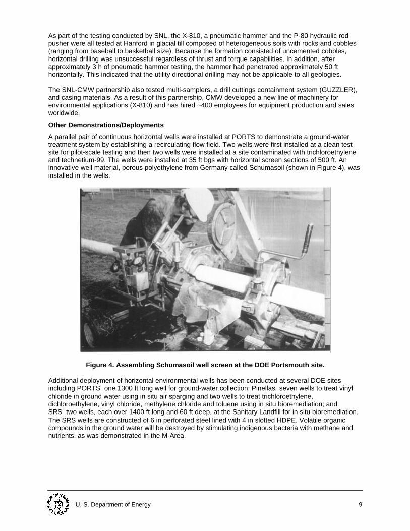
A parallel pair of continuous horizontal wells were installed at PORTS to demonstrate a ground-watertreatment system by establishing a recirculating flow field. Two wells were first installed at a clean testsite for pilot-scale testing and then two wells were installed at a site contaminated with trichloroethyleneand technetium-99. The wells were installed at 35 ft bgs with horizontal screen sections of 500 ft. Aninnovative well material, porous polyethylene from Germany called Schumasoil (shown in Figure 4), wasinstalled in the wells.
Figure 4. Assembling Schumasoil well screen at the DOE Portsmouth site. Additional deployment of horizontal environmental wells has been conducted at several DOE sitesincluding PORTS� one 1300 ft long well for ground-water collection; Pinellas� seven wells to treat vinylchloride in ground water using in situ air sparging and two wells to treat trichloroethylene,dichloroethylene, vinyl chloride, methylene chloride and toluene using in situ bioremediation; andSRS� two wells, each over 1400 ft long and 60 ft deep, at the Sanitary Landfill for in situ bioremediation.The SRS wells are constructed of 6 in perforated steel lined with 4 in slotted HDPE. Volatile organiccompounds in the ground water will be destroyed by stimulating indigenous bacteria with methane andnutrients, as was demonstrated in the M-Area.
10 U.S. Department of Energy
SECTION 4
Competing Technologies
The baseline technology for access to contaminated media is vertical wells. The well itself may be usedfor a variety of treatment technologies including ground-water extraction (e.g., pump and treat), soilvapor extraction, and air sparging. In competition with horizontal wells as a means of enhanced access to contaminated media are inducedfractures and interceptor trenches.
• Induced fractures are created by injecting fluid (pneumatically or hydraulically) into a wellbore.Typical dimensions are three times the depth for depth ranges of 5 to 16 ft (maximum dimensionincreases with increasing depth and decreasing permeability).
The primary application of induced fractures is to increase both the discharge of and the areaaffected by a well. Induced fractures may increase well discharge 10 to 50 times compared toconventional wells in rock or silty clay (relative increase in performance is greatest in tightestformations). Induced fractures may also be used to deliver solid compounds into the subsurface(e.g., nutrients to enhance bioremediation, reactants to oxidize or reduce organic compounds).
• Other than vertical wells, trenches are the most widely used method for controlling subsurface
fluids and recovering contaminants. Trenches are installed using widely available standardconstruction equipment (e.g., backhoe) and more sophisticated continuous trenching machines.The primarily application of trenches is for ground-water recovery (to intercept the migration of theground-water plume) or to increase the rate of recovery in low permeability soils. Typically a cap isrequired over the trench to prevent surface water or air from entering the trench.
Both horizontal wells and trenches significantly increase the access (or exposure) to contaminantscompared to vertical wells. The geometries of horizontal wells and trenches are similar. Trenches maybe preferred for applications requiring shallow surface access, while horizontal wells may be preferred fordeeper applications or in situations with surface access restrictions.
Technology Applicability
Horizontal environmental wells enhance access to soil and ground-water contaminants. They provide improved access to and potential monitoring of contaminants in areas with surface restrictions (buildings,tanks, utility lines, pits, lagoons, etc.); hydraulic control of a contaminant plume at the leading edge(when installed at the leading edge); and increased surface area contact with the contaminants.
• Horizontal environmental wells may also increase the remediation efficiency compared to thebaseline technology by encompassing a larger zone of influence using long screen zones and byreducing operating expenses using fewer wells and therefore saving money on operation andmaintenance (O&M).
• Limitations of horizontal environmental wells include a requirement for accurate drilling installationand minimal water table fluctuation for light non-aqueous phase liquid recovery; limited verticalinfluence of the well due to anisotropy; difficult drilling and installation conditions due to thepresence of coarse gravels; and treatment of immobile non-aqueous phase liquid or stronglysorbed contaminants.
TECHNOLOGY APPLICABILITY ANDALTERNATIVES
U. S. Department of Energy 11
• Horizontal drilling concerns include reduced permeability of the geologic formation during wellinstallation caused by compaction drilling tools or due to introduced drilling fluids (same as forvertical drilling); potential for drilling fluids to foul uncontaminated areas, damage equipment andinterrupt utility services, or compromise soil stability beneath pavement and structures.
Patents/Commercialization/Sponsor
Information on patent and licensing issues, commercial involvement by private industry, and technologydevelopment sponsors,is available from the Technical Contact listed in Section 1.
12 U.S. Department of Energy
SECTION 5
Methodology
Horizontal wells cost more to install but much less to maintain, and because each typically performs the work of several vertical wells, there is simply no doubt that, where they can be practically installed, theyare the technology of choice. Horizontal wells, in short, in many places already are, and in most otherswill soon be, the new baseline. Because horizontal wells are a mature technology, costs may be determined by standard accounting (fordemonstrations) and by direct inquiry for various implementations and deployments.
• Not surprisingly, costs of horizontal wells range widely based on drilling method and size of rig;type of drilling tool, drilling fluid, and guidance system; vertical depth and total well length; sitegeology; well materials; and number of personnel on site.
• In general, cost and performance data outside DOE are not readily available because there is nocompelling reason for private companies to track or report such data. Additional performance dataare needed to compare costs of various horizontal environmental well applications.
Cost Analysis
Based on past projects, the cost of a horizontal well (PVC or HDPE well casing) using a small tomedium-sized utility-type drilling rig, a radio beacon/receiver guidance system, a simple drilling fluidsystem, and a compaction drilling tool is ~$164/m ($50/ft) (EPA, 1994). More sophisticated directional drilling methods using a larger drilling rig, a magnetometer-accelerometerguidance system and a more advanced drilling fluid system and drilling tool or mud motor areapproximately (assuming PVC or HDPE well casing):
• $1036/m or $316/ft (< 25 ft depth)
• $602/m or $183/ft (25 to 100 ft depth)
• $744/m or $227/ft (>100 ft depth)
The higher cost of the shallow wells is attributed to the shorter length and fixed mobilization and dailycosts for equipment. Thus, the cost per unit length is less for longer wellbores where these costs can beminimized.
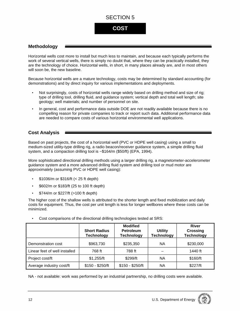
• Cost comparisons of the directional drilling technologies tested at SRS:
Modified River Short Radius Petroleum Utility Crossing Technology Technology Technology Technology Demonstration cost $963,730 $235,350 NA $230,000
Linear feet of well installed 768 ft 788 ft – 1440 ft
Project cost/ft $1,255/ft $299/ft NA $160/ft
Average industry cost/ft $150 - $250/ft $150 - $250/ft NA $227/ft
NA - not available: work was performed by an industrial partnership, no drilling costs were available.
COST
U. S. Department of Energy 13
• Utility technology drilling costs determined in development testing by SNL were in the range of $25to $75/ft, excluding the cost of the casing/screen materials.
• During well installation at Pinellas, the average cost for the horizontal wells was ~$80/ft includingthe well materials which were built on-site.
• For horizontal wells installed at John F. Kennedy International Airport for air sparging (or soil vaporextraction), the installation of a single horizontal well to replace a row of eight to twelve verticalwells and associated trenching/piping, reduced installation costs by more than one half from $270per lin ft to $110 per lin ft (Fournier and Pressly, 1996).
Cost Conclusions
Although drilling and installation of horizontal wells is more expensive compared to vertical wells, theincreased efficiency (one horizontal well may replace several vertical wells) and increased performance(horizontal wells may remediate a plume faster because of the greater contact with contaminants byusing longer well screens) of horizontal wells make the life cycle cost of horizontal wells less expensive(including installation, O&M, and remediation).
• Capital costs of one horizontal well were similar to five vertical wells, but the O&M cost for thehorizontal well was less than 1/3 that of the five vertical wells (EPA, 1994).
• O&M costs for horizontal well systems are lower than for a vertical well field due to the lowernumber of pumps required, reduced time for routine sampling and lower power consumption.However, it may be more expensive to recondition horizontal wells compared to vertical wells.
Costs may be significantly reduced by minimizing investigative-derived waste and the associated wastemanagement costs when horizontal wells are installed outside the main portion of the ground-waterplume (e.g., below the plume).
14 U.S. Department of Energy
SECTION 6
Regulatory Considerations
• Directional drilling technology requires the same permits as required for other drilling technologies.
• Hazardous waste drilling activities typically require that investigative-derived wastes (drilling fluids,cuttings, and equipment decontamination fluids) be handled according to the ResourceConservation and Recovery Act.
• When using an organic polymer-based drilling fluid, a chlorine additive is used in the drilling fluidmakeup water and the development water. Degradation of the drilling fluid is due to increasedmicrobial activity requiring a subsequent additive to inhibit bacterial growth. If a disinfectant cannotbe introduced to the subsurface, then an alternate drilling fluid (such as a bentonite-based drillingfluid) should be used.
• Permit requirements are site specific and depend on the selected remediation and/or use of thehorizontal well. All permits must be worked out with the appropriate regulators and may include:
— an air permit for discharge of treated vapor extracted from the subsurface, — Comprehensive Environmental Recovery, Compensation, and Liability Act and/or Resource Conservation and Recovery Act permitting depending on site-specific requirements,
— underground injection permits if injection of gases or fluids (e.g., air, nutrients) into the subsurface is required for the treatment, and/or
— National Environmental Protection Act review for federal projects.
Safety, Risks, Benefits and Community Reaction
Worker Safety
• Potential worker safety risks include those associated with standard construction operations.
• Occupational Safety and Health Administration (OSHA) requirements must be reviewed becausedirectional drilling, like all drilling methods, involves high noise levels and hazards associated withdrilling near overhead or subsurface power lines or utilities.
• All field personnel must be 40 h OSHA trained as required in 29 Code of Federal Regulations(CFR) 1910.120 for hazardous waste operations.
• Other health and safety issues for horizontal environmental wells are essentially equivalent tothose for conventional technologies such as ground-water extraction in a vertical well field.
Community Safety
• Directional drilling does not produce routine release of contaminants.
• Investigative-derived wastes (drilling fluids, cuttings, and equipment decontamination fluids)should be handled in a manner that prevents contact with the surrounding ground surface.
• No unusual or significant safety concerns are associated with transport of equipment or othermaterials associated with horizontal environmental wells.
Environmental Impacts
• Directional drilling and subsequent use of horizontal environmental wells minimizes clearing andother activities that would be required to install a comparable vertical well field.
• Investigative-derived waste are minimized when the horizontal well is installed outside of the mainportion of the ground-water plume (e.g., below the plume).
REGULATORY AND POLICY ISSUES
U. S. Department of Energy 15
• Visual impacts are minor and the ground surface is minimally disturbed by emplacement ofhorizontal wells.
• Operation of the drilling equipment creates moderate to high noise in the immediate vicinity.
Potential Exposures
• Potential exposures are equal to or less than those associated with vertical drilling.
Socioeconomic Impacts And Community Perception
• Directional drilling and horizontal wells have minimal economic or labor force impacts.
• The general public has limited familiarity with horizontal environmental wells; however, thetechnology can be explained to the public with ease similar to that of pump-and-treat technologies.
16 U.S. Department of Energy
SECTION 7
Design Issues
During the SRS demonstrations several pre-drilling activities that should be considered were identified.
• A thorough description of the target zone and surrounding geology/hydrogeology should be madeavailable to the well designers and the drilling subcontractor.
• A description of the well completion requirements such as well screen size, filter pack size (if pre-pack screen is specified), and specifications of the well material should be made available to thewell designers and the drilling subcontractor.
• A thorough design of the wellbore should be prepared. The design should include the locations ofthe entry hole and exit hole (if needed), the location of the well screen, and the radius of curvaturerequired to place the well screen correctly.
• An engineering calculation brief that describes and sums the forces experienced by the wellmaterials during well completion activities is required. The calculation brief should delineate thestrength requirements of the well materials and evaluate the utility of the chosen well materials.
• The steering tool should be calibrated onsite by a qualified technician before each use.
• The drilling subcontractor should be procured and involved in the design process as early aspossible. Pre-drilling meetings should be held, and all the above items should be discussed withthe drilling subcontractor.
The project manager or the consultant must be experienced in designing horizontal wells, procuringhorizontal well contractors, and performing horizontal well construction oversight.
Implementation Considerations
Complete characterization of the site hydrogeology for well placement and geology and geochemistry tounderstand the drilling conditions. Careful and vigilant oversight during installation (e.g., checking for electromagnetic interference, poorcalculations, and surface elevations) is required. Drilling the pilot hole too quickly may result in sharp bends in the wellbore, putting unnecessary stress onthe well materials (compared to the desired smooth, uniform curve). Experience from the SRS demonstration yields the following recommendations:
• Well materials should be thoroughly inspected before well completion activities begin, with specialemphasis placed on the pin and box of each piece if threaded joints are used.
• Well materials should be installed using a roller system to minimize bending at the surface.
• Surface-launched wellbores require that the drilling rig is anchored firmly to the ground and thatthe anchorage is able to resist maximum pushing and pulling capacity of the drilling rig.
• The steering system should be proven as an accurate survey tool or a secondary survey should beused to confirm the location of the downhole assembly.
• The drilling crew should be experienced in installing horizontal wells in conditions similar to thosefound at the proposed drilling site and use of all equipment required.
• The drilling crew should make every effort to control the loss of drilling fluid circulation. Lostcirculation zones should be plugged when they are encountered.
LESSONS LEARNED
U. S. Department of Energy 17
Technology Limitations/Needs for Future Development More experience with environmental horizontal drilling under a variety of subsurface conditions willensure better well installations at reduced costs.
Future Technology Selection Considerations
Directional drilling of horizontal environmental wells has been demonstrated as an enhanced accessmethod for treatment of contaminated soils and ground-water plumes. Remediation efficiency may beenhanced by increased surface area for reaction, similarity of well profile and contaminant plumegeometry, wellbore access to areas beneath existing facilities, and drilling along facility boundaries tocontrol plume migration. Each site must be assessed for the utility of horizontal wells. Heterogeneous soils with rocks and cobblesmay limit the ability to drill while soils with at least 15 to 20 percent clay may improve the drillingperformance.


U. S. Department of Energy A-1
APPENDIX A
Charles Machine Works, Inc. 1996. The Green Book, Horizontal Directional Drilling Systems: A New Dimensionfor Remediation. CMW-950. Published by The Charles Machine Works, Inc., Perry, Oklahoma.
Fournier, L. B. and N. C. Pressly. 1996. "Horizontal Wells Offer Economic Advantage at John F. KennedyInternational Airport,” Horizontal News, Vol. 2, No. 1, pp. 1-3.
Goranson, C. 1992. Applicability of Petroleum Horizontal Drilling Technology to Hazardous Waste SiteCharacterization and Remediation. LBL-33957, UC-000. Lawrence Berkeley Laboratory, University ofCalifornia, Berkeley, California.
Horizontal News, 1995. Published by the Colorado Center for Environmental Management for the Department ofEnergy Office of Science and Technology, Vol. 1., No. 1.
Kaback, D. S., B. B. Looney, J. C. Corey, L. M. Wright, and J. L. Steele. 1989. "Horizontal Wells for In-SituRemediation of Ground Water and Soils". In Proceedings NWWA Outdoor Action Conference, Orlando,Florida, pp. 121-135.
Kaback, D. S., B. B. Looney, J. C. Corey, and L. M. Wright. 1989. Well Completion Report on Installation ofHorizontal Wells for In Situ Remediation Tests (U). WSRC-RP-89-784. Westinghouse Savannah RiverCompany, Savannah River Site, Aiken, South Carolina.
Kaback, D. and D. Oakley. 1996. Horizontal Environmental wells in the United States: A Catalog. Published bythe Colorado Center for Environmental Management for the Department of Energy Office of Science andTechnology.
Langseth, D. 1990. “Hydraulic Performance of Horizontal Wells,” Hazardous Materials Control Research InstituteSuperfund 90 Proceedings. Washington DC, pp. 398-408.
Muck, M. T., N. E. Korte, and R. L. Siegrist. 1995. "A Horizontal-Well Recirculation System for Ground-WaterTreatment: How Does It Perform?" Horizontal News, Vol. 1, No. 2, pp. 6.
Muck, M. T. et al. 199x. Field evaluation of a Horizontal Well Recirculation System for Ground-Water Treatment:Pilot Test at the Clean Test Site Portsmouth Gaseous Diffusion Plant Piketon, Ohio. In draft.
Plummer, C. 1995. "Horizontal Versus Vertical Well Performance,” Horizontal News, Vol. 1, No. 2, pp. 1-3.
Staller, G. E., R. P. Wemple, and R. R. Layne. 1994. Casing Pull Tests for Directionally Drilled EnvironmentalWells. SAND94-2387, UC-2000. Sandia National Laboratories, Albuquerque, New Mexico andLivermore, California.
U. S. Environmental Protection Agency. 1994. Alternative Methods for Fluid Delivery and Recovery. EPA/625/R-94/003. U.S. EPA Office of Research and Development, Washington D.C.
Wemple, R. P., R. D. Meyer, G. E. Staller, and R. R. Layne. 1994. Final Report for SNL/NM EnvironmentalDrilling Project. SAND94-2388, UC-2000. Sandia National Laboratories, Albuquerque, New Mexico andLivermore, California.
Wilson, D. D. and D. S. Kaback. 1993. Industry Survey for Horizontal Wells Final Report. WSRC-TR-93-511.Westinghouse Savannah River Company, Savannah River Site, Aiken, South Carolina.
REFERENCES
A-2 U.S. Department of Energy
WSRC. 1992. Demonstration of Eastman Christensen Horizontal Drilling System, Integrated Demonstration Site,Savannah River Site. WSRC-TR-92-577. Westinghouse Savannah River Company, Savannah River Site,Aiken, South Carolina.
WSRC. 1992. Demonstration of a Utility Industry Horizontal Drilling System: Horizontal Well AMH-5 InstallationReport. WSRC-TR-93-008. Westinghouse Savannah River Company, Savannah River Site, Aiken, SouthCarolina.
WSRC. 1993. Demonstration of a River Crossing Technology for Installation of Environmental Horizontal Wells:AMH-6 and AMH-7 Installation Report. Westinghouse Savannah River Company, Savannah River Site,Aiken, South Carolina.
WSRC. 1993. Summary Report of the Drilling Technologies Tested at the Integrated Demonstration Project forCleanup of Organic Contaminants in Soils and Ground Water at Non-Arid Sites. WSRC-TR-93-565.Westinghouse Savannah River Company, Savannah River Site, Aiken, South Carolina.
U. S. Department of Energy B-1
APPENDIX B
bgs below ground surface
CFR Code of Federal Regulations
CMW Charles Machine Works
DBTR Directional Boring Test Range
DOE United States Department of Energy
EPA Environmental Protection Agency
ft foot (feet)
gpm gallons per minute
h hour (s)
HPDE high-density polyethylene
KAFB Kirtland Air Force Base
lin ft linear foot
m meter
O&M operation and maintenance
OSHA Occupational Health and Safety Administration
PORTS Portsmouth Gaseous Diffusion Plant
ppb parts per billion
PVC polyvinyl chloride
SNL Sandia National Laboratories
SRS Savannah River Site
US United States
VOCs volatile-organic contaminants
ACRONYMS AND ABBREVIATIONS