hooghan hózhó - pavilion construction hozho/2013 05 28 spec permit.pdfhooghan hózhó . mixed-use...
TRANSCRIPT

Hooghan Hózhó Mixed-Use Development 201 E Coal Avenue, Gallup, NM
Project Manual
Owner: CARE66 Community Area Resource Enterprise P0 Box 4298 Gallup, NM 87301 Sanjay Choudhrie, Executive Director Rhonda Berg, Director of Housing Development & Project Contact: 505-722-0022 [email protected] Engineer: ABQ Engineering 8102 Menaul Boulevard Albuquerque, NM 87110 505.255.7802
Architect: Thomas Gifford Architecture│Urban Design 805 Early Street Suite C204 Santa Fe, NM 87501 505.690.5898 [email protected]

Table of Contents: Hooghan Hózhó
1
Table of Contents: Hooghan Hózhó
DIVISION 00 - PROCUREMENT AND CONTRACTING REQUIREMENTS 00 01 01 Project Title Page 00 01 07 Seals Page 00 01 10 Table of Contents 00 30 00 Available Project Information 00 30 21 Survey Information 00 30 32 Geotechnical Data 00 40 00 Procurement Forms and Supplements 00 43 36 Proposed Subcontractors Form + List 00 43 43 Wage Rates Form 00 43 73 Proposed Schedule of Values Form 00 44 00 Agent’s Affidavit 00 45 00 Proposal Form Supplements 00 45 00a Buy American 00 45 00b Certificate Regarding Disbarment 00 45 00c Labor Compliance Forms 00 45 19 Non-Collusion Affidavit 00 45 33 Non-Segregated Facilities Affidavit 00 60 00 Project Forms 00 61 13 Performance and Payment Bond Form 00 62 73 Schedule of Values Form 00 62 76 Application for Payment Form 00 70 00 Conditions of the Contract Exhibit A Project Description Exhibit B General Conditions
Exhibit C Special Conditions to the Rider to Construction Agreement and General Conditions Exhibit D Schedule of Values Exhibit E Plans and Specifications Exhibit F Application for Payment Exhibit G Project Schedule Exhibit H Bonds Exhibit I Change Order Exhibit J Davis Bacon Wage Rates Exhibit K Supplemental Conditions for ARRA and EPA Funded Projects
DIVISION 01 - GENERAL REQUIREMENTS
01 11 00 Summary of Work 01 21 13 Cash Allowances 01 23 00 Alternates 01 25 00 Substitution Procedures 01 26 63 Change Orders 01 31 00 Project Management and Coordination 01 31 19 Project Meetings 01 32 00 Construction Progress Documentation 01 32 21 Owner Pre-Construction Conference 01 33 00 Submittal Procedures 01 40 00 Quality Requirements 01 42 00 Reference standards 01 45 23 Testing and Inspecting Services 01 50 00 Temporary Facilities and Controls 01 66 00 Product Storage and Handling Requirements 01 70 00 Execution and Closeout Requirements 01 73 29 Cutting and Patching 01 74 00 Cleaning and Waste Management 01 78 00 Closeout Submittals (Warranties and Bonds) 01 78 23 Operation and Maintenance Data 01 78 33 Bonds + Warranties 01 78 39 Project Record Documents 01 93 00 Facility Maintenance
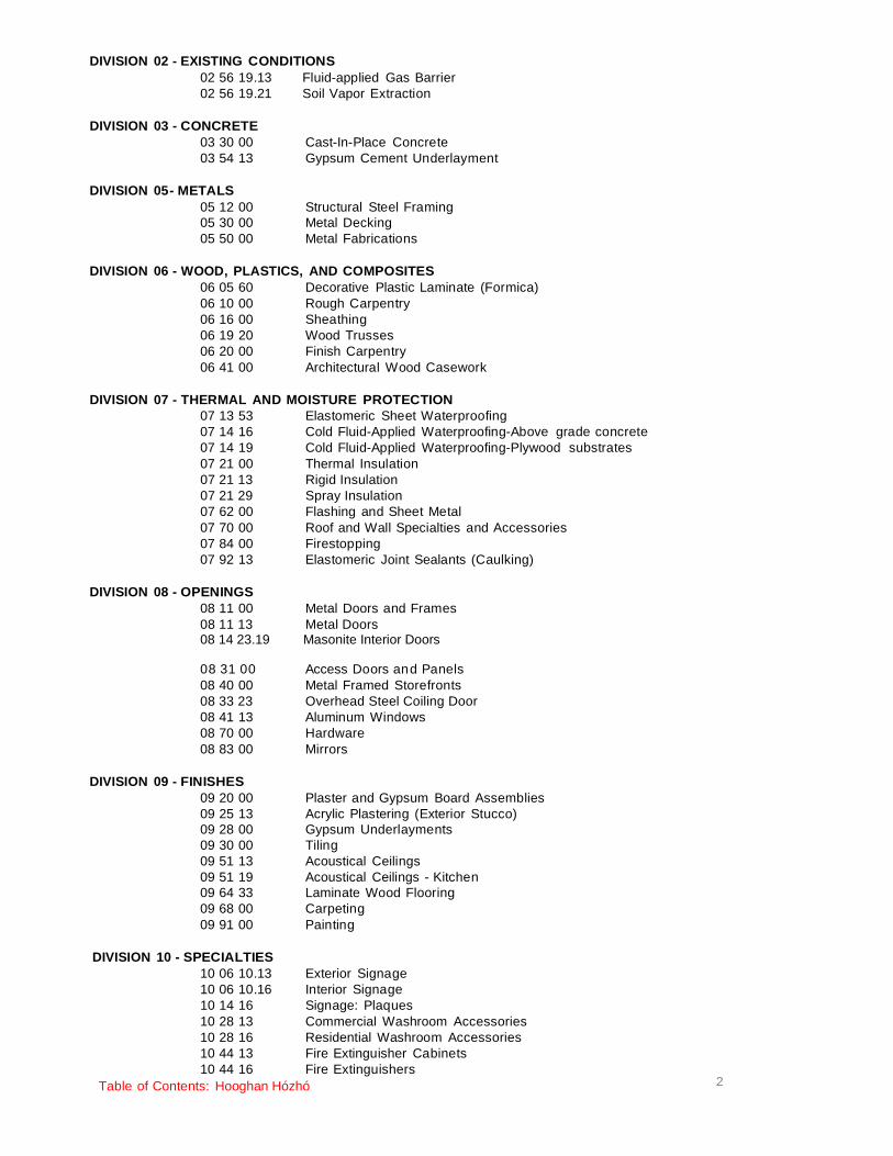
Table of Contents: Hooghan Hózhó
2
DIVISION 02 - EXISTING CONDITIONS 02 56 19.13 Fluid-applied Gas Barrier 02 56 19.21 Soil Vapor Extraction
DIVISION 03 - CONCRETE 03 30 00 Cast-In-Place Concrete 03 54 13 Gypsum Cement Underlayment
DIVISION 05 - METALS
05 12 00 Structural Steel Framing 05 30 00 Metal Decking 05 50 00 Metal Fabrications
DIVISION 06 - WOOD, PLASTICS, AND COMPOSITES
06 05 60 Decorative Plastic Laminate (Formica) 06 10 00 Rough Carpentry 06 16 00 Sheathing 06 19 20 Wood Trusses 06 20 00 Finish Carpentry 06 41 00 Architectural Wood Casework
DIVISION 07 - THERMAL AND MOISTURE PROTECTION
07 13 53 Elastomeric Sheet Waterproofing 07 14 16 Cold Fluid-Applied Waterproofing-Above grade concrete 07 14 19 Cold Fluid-Applied Waterproofing-Plywood substrates 07 21 00 Thermal Insulation 07 21 13 Rigid Insulation 07 21 29 Spray Insulation 07 62 00 Flashing and Sheet Metal 07 70 00 Roof and Wall Specialties and Accessories 07 84 00 Firestopping 07 92 13 Elastomeric Joint Sealants (Caulking)
DIVISION 08 - OPENINGS 08 11 00 Metal Doors and Frames 08 11 13 Metal Doors 08 14 23.19 Masonite Interior Doors
08 31 00 Access Doors an d Panels 08 40 00 Metal Framed Storefronts 08 33 23 Overhead Steel Coiling Door 08 41 13 Aluminum Windows 08 70 00 Hardware 08 83 00 Mirrors
DIVISION 09 - FINISHES
09 20 00 Plaster and Gypsum Board Assemblies 09 25 13 Acrylic Plastering (Exterior Stucco) 09 28 00 Gypsum Underlayments 09 30 00 Tiling 09 51 13 Acoustical Ceilings 09 51 19 Acoustical Ceilings - Kitchen 09 64 33 Laminate Wood Flooring 09 68 00 Carpeting 09 91 00 Painting
DIVISION 10 - SPECIALTIES
10 06 10.13 Exterior Signage 10 06 10.16 Interior Signage 10 14 16 Signage: Plaques 10 28 13 Commercial Washroom Accessories 10 28 16 Residential Washroom Accessories 10 44 13 Fire Extinguisher Cabinets 10 44 16 Fire Extinguishers

Table of Contents: Hooghan Hózhó
3
10 55 13 Postal Cluster Mailboxes 10 55 26 Parcel Mailboxes 10 56 23 Wire Storage Shelving
DIVISION 11 - EQUIPMENT 11 31 00 Residential Appliances 11 68 00 Play Field Equipment and Structures
DIVISION 12 - FURNISHINGS
12 20 00 Window Coverings: Commercial 12 21 13 Residential Horizontal Louver Blinds 12 93 13 Bicycle Racks 12 93 43 Site Seating and Tables & TRASH CANS
DIVISION 14 - CONVEYING EQUIPMENT
14 21 00 Electric Traction Elevators
DIVISION 21 - FIRE SUPRESSION 21 13 00 Fire-Suppression Sprinkler Systems
DIVISION 22 - PLUMBING
22 10 00 Plumbing Basic Material 22 11 00 Facility Water Distribution 22 13 00 Facility Sanitary Sewage 22 40 00 Plumbing Fixtures 22 47 00 Drinking Fountains and Water Cooler
DIVISION 23 - HEATING, VENTILATING AND AIR CONDITIONING (HVAC)
23 00 00 Heating, Ventilating and A/C (HVAC) 23 05 93 Testing, Adjusting and Balancing for HVAC 23 07 19 HVAC Piping Insulation 23 11 00 Facility Fuel Piping 23 30 00 HVAC Air Distribution 23 37 00 Air Outlets and Inlets
DIVISION 26 - ELECTRICAL
26 05 00 Common Work Results for Electrical 26 05 13 Wire & Cable 26 10 00 Wiring Methods 26 11 10 Conduit 26 21 00 Electric Service
26 24 16 Panel boards 26 27 26 Wiring Devices 26 28 16 Enclosed Switches and Circuit Breakers 26 50 00 Lighting
DIVISION 27 - COMMUNICATIONS
27 00 00 Communications: Tele, Cable TV, Security Systems 27 05 13 Communications Services
DIVISION 28 - ELECTRONIC SAFETY AND SECURITY
DIVISION 31
28 31 00 - EARTHWORK
Fire Alarm
31 00 00 Earthwork (Backfilling & Compaction) 31 10 00 Site Clearing 31 22 19 Site Finish Grading 31 25 00 Erosion and Sedimentation Control
DIVISION 32 - EXTERIOR IMPROVEMENTS
32 17 13 Parking Bumpers 32 31 00 Fences and Gates
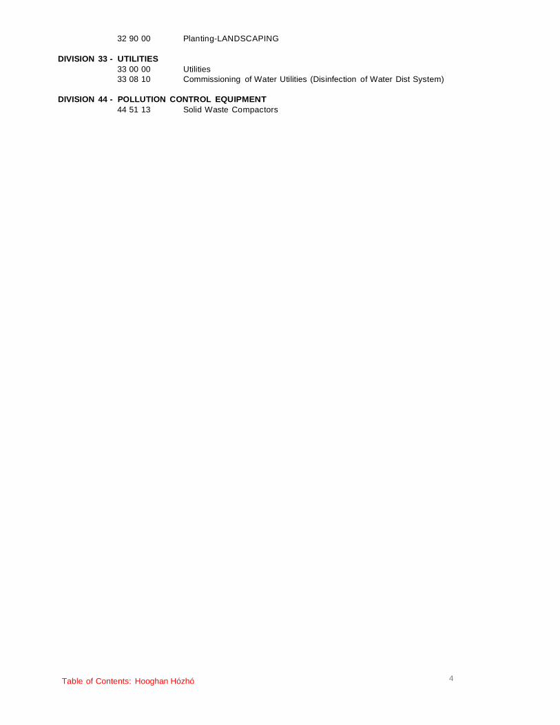
Table of Contents: Hooghan Hózhó
4
32 90 00 Planting-LANDSCAPING
DIVISION 33 - UTILITIES 33 00 00 Utilities 33 08 10 Commissioning of Water Utilities (Disinfection of Water Dist System)
DIVISION 44 - POLLUTION CONTROL EQUIPMENT
44 51 13 Solid Waste Compactors


SECTION 00 01 07 – SEALS PAGE
SECTION 00 01 07 – SEALS PAGE
This Engineering seal applies to the following Divisions only: Division 22 – Plumbing
Division 23 – Heating, Ventilating and Air Conditioning (HVAC) Division 26 – Electrical Division 31 – Site Division 33 – Utilities
And parts of these Divisions: Division 03 – Concrete Division 04 -- Masonry Division 05 – Metals Division 06 – Wood
Civil / Structural Electrical
Mechanical (HVAC) Mechanical (Plumbing)
END OF SECTION 00 01 07 – SEALS PAGE
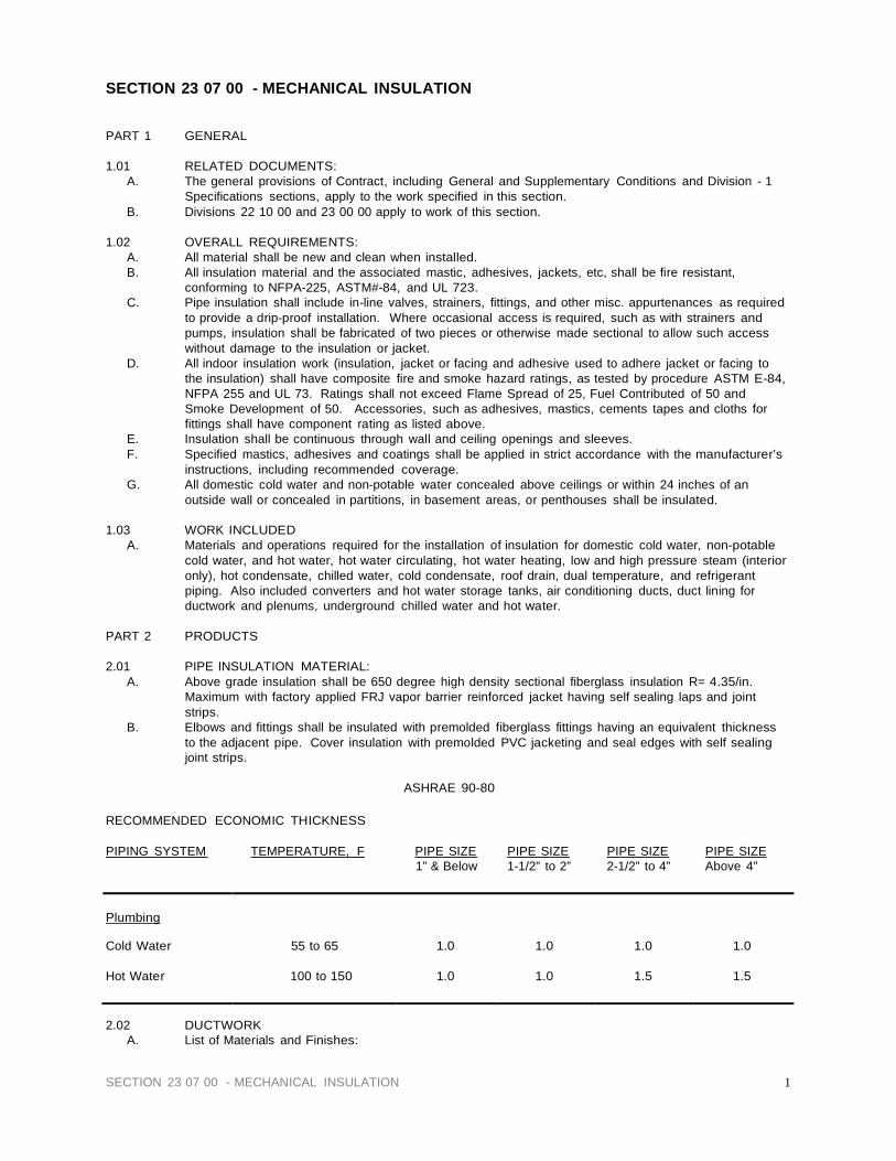
SECTION 23 07 00 - MECHANICAL INSULATION
PART 1 GENERAL
1.01 RELATED DOCUMENTS: A. The general provisions of Contract, including General and Supplementary Conditions and Division - 1
Specifications sections, apply to the work specified in this section. B. Divisions 22 10 00 and 23 00 00 apply to work of this section.
1.02 OVERALL REQUIREMENTS:
A. All material shall be new and clean when installed. B. All insulation material and the associated mastic, adhesives, jackets, etc, shall be fire resistant,
conforming to NFPA-225, ASTM#-84, and UL 723. C. Pipe insulation shall include in-line valves, strainers, fittings, and other misc. appurtenances as required
to provide a drip-proof installation. Where occasional access is required, such as with strainers and pumps, insulation shall be fabricated of two pieces or otherwise made sectional to allow such access without damage to the insulation or jacket.
D. All indoor insulation work (insulation, jacket or facing and adhesive used to adhere jacket or facing to the insulation) shall have composite fire and smoke hazard ratings, as tested by procedure ASTM E-84, NFPA 255 and UL 73. Ratings shall not exceed Flame Spread of 25, Fuel Contributed of 50 and Smoke Development of 50. Accessories, such as adhesives, mastics, cements tapes and cloths for fittings shall have component rating as listed above.
E. Insulation shall be continuous through wall and ceiling openings and sleeves. F. Specified mastics, adhesives and coatings shall be applied in strict accordance with the manufacturer’s
instructions, including recommended coverage. G. All domestic cold water and non-potable water concealed above ceilings or within 24 inches of an
outside wall or concealed in partitions, in basement areas, or penthouses shall be insulated.
1.03 WORK INCLUDED A. Materials and operations required for the installation of insulation for domestic cold water, non-potable
cold water, and hot water, hot water circulating, hot water heating, low and high pressure steam (interior only), hot condensate, chilled water, cold condensate, roof drain, dual temperature, and refrigerant piping. Also included converters and hot water storage tanks, air conditioning ducts, duct lining for ductwork and plenums, underground chilled water and hot water.
PART 2 PRODUCTS
2.01 PIPE INSULATION MATERIAL:
A. Above grade insulation shall be 650 degree high density sectional fiberglass insulation R= 4.35/in. Maximum with factory applied FRJ vapor barrier reinforced jacket having self sealing laps and joint strips.
B. Elbows and fittings shall be insulated with premolded fiberglass fittings having an equivalent thickness to the adjacent pipe. Cover insulation with premolded PVC jacketing and seal edges with self sealing joint strips.
ASHRAE 90-80
RECOMMENDED ECONOMIC THICKNESS
PIPING SYSTEM TEMPERATURE, F PIPE SIZE PIPE SIZE PIPE SIZE PIPE SIZE
1” & Below 1-1/2” to 2” 2-1/2” to 4” Above 4”
Plumbing
Cold Water
55 to 65
1.0
1.0
1.0
1.0
Hot Water
100 to 150
1.0
1.0
1.5
1.5
2.02 DUCTWORK A. List of Materials and Finishes:
SECTION 23 07 00 - MECHANICAL INSULATION 1

1. Air Conditioning, Supply/Return, Exhaust, Air Intake, Plenums, and Rectangular Ducts Within Mechanical Equipment Room: a. Shall be 1” thick 705 rigid board applied with mechanical fasteners. Seal all joints and
breaks with 3” wide ASJ tape. All punctures shall be sealed with ASJ patches. Where stiffening angles are 1-1/2”, insulation shall be 1-1/2” thick.
2. All Rectangular Supply and Return Ducts for Heating, Cooling, Dual Temperature and Ventilating: a. A 2” thick 3/4 lb./cu. ft. density with a facing of reinforced foil draft laminate. Use OCF All
Service Wrap or approved equal. The vapor barrier shall be legibly printed by the manufacturer to show flame spread smoke developed, nominal thickness and type of insulation. The duct wrap shall be applied over clear dry sheet metal duct work that has been sealed air-tight at all seams and joints. Duct Wrap shall be installed to allow maximum fullness at corners (avoid excessive compression).
b. Use manufacturer’s suggested “stretchout” information. Insulation shall be butted tightly at joints and vapor barrier facing shall be overlapped a minimum of 2”. All seams shall be stapled approximately 6” on center with outward clinching staples, then sealed with a foil vapor barrier tape. Where ducts are over 24” in width, the duct wrap shall be additionally secured to the bottom of the rectangular ducts with mechanical fasteners spaced on 18” centers (maximum), to prevent sagging of insulation. Seal penetrations so as to provide a vapor-tight system.
3. All connections to Fiberglass Flexible Duct shall be installed in sizes and locations where indicated on drawings. The flexible duct shall have: maximum interior air temperature of 200° F, maximum static pressure 10”, maximum negative air pressure 1/2” a C value of .23 BTU/hr./ft.2/°F. or approved equal.
B. Duct Lining for Rectangular heating and Cooling Ducts: 1. Shall be 1” thick 3 lb./cu./ft. density with a black fire and mold resistant coating. Use Aeroflex or
Engineers approved equal. a. Application:
1) All portions of duct designated to receive duct liner shall be completely covered with Duct Liner. Transverse joints shall be neatly butted and there shall be no interruptions or gaps.
2) The black coated surface of the Duct Liner shall face the air stream. 3) The Duct Liner shall be adhered to the sheet metal with 100% coverage of adhesive
and all exposed leading edges and all transverse joints coated with adhesive. Adhesive shall conform to Adhesive and Sealant Council Standards for Adhesive for Duct Liner, ASC-A-7001C-1972.
4) The Duct Liner shall be additionally secured with mechanical fasteners (Mechanical fasteners hall conform to Mechanical Fastener Standard MF-1-1971, available from Sheet Metal and Air Conditioning Contractors National Association, which shall compress the duct liner sufficiently to hold it firmly in place.
5) Duct Liner shall be cut to assure overlapped and compressed longitudinal corner joints.
6) For velocities to 2,000 feet per minute, fasteners shall start within 3” of the upstream transverse edges of the Aeroflex Duct Liner and 3” from the longitudinal joints and shall be spaced at a maximum of 12” o.c. around the perimeter of the duct, except that they may be a maximum of 12” from corner break. Elsewhere they shall be a maximum of 18” o.c. except that they shall be placed not more than 6” from a longitudinal joint of the liner or 12” from a corner break.
7) For velocities from 2,001 to 4000 feet per minute, fasteners shall start within 3” of the upstream transverse edges of the liner and 3” from the longitudinal joints and shall be spaced at a maximum of 6” o.c. around the perimeter of the duct, except that they may be a maximum of 6” from a corner break. Elsewhere they shall be a maximum of 16” o.c. , except that they shall be placed not more than 6” from a longitudinal joint of the liner nor 12” from a corner break. In addition to the adhesive edge coating of transverse joints, any longitudinal joints shall be similarly coated with adhesive.
8) For velocities from 4,000 to 6,000 feet per minute. Same as 2,001 to 4,000 FPM except that metal nosing shall be installed to secure the Aeroflex Duct Liner at all upstream transverse edges.
PART 3 EXECUTION
3.01 GENERAL
A. Insulation shall be applied to surfaces after successful testing and after items have been properly installed and cleaned. Workmanship in all cases shall represent the best quality. The finished surface of insulation materials shall be smooth, free of wrinkles, ridges, gaps, and cracks.

B. Seal all exposed insulation at ends and edges.
3.02 PIPING SYSTEMS A. Insulate all piping systems as follows: B. Domestic cold, hot, and re-circulating water lines shall be insulated with 1/2" thick insulation. C. Pipe insulation at hangers shall be half or full round calcium sibilate of the same thickness and jacketing
as the adjoining insulation. The calcium silicate shall rest on a heavy gauge galvanized sheet metal shield and extend 2" beyond shield length each way. The shield gauge and length are as follows:
Pipe size Gauge Length 1/2" - 2-1/2" 18 12"
D. Any piping subject to freezing shall be covered with another additional layer of 2-inch fiberglass insulation of the same finish as specified for the particular service when not subject to freezing.
E. Piping which is exposed to weather or called to be electric heated/weatherproofed shall be covered - in addition to insulation and finishes specified for freezing - with corrugated aluminum jacket 0.016 inch thick applied with aluminum lock-type bands, 12-inches apart. Fittings, flanges, strainers and valves shall be coated with BF 65-07.
F. Handicapped Lavatories: 1. Insulate all water piping and the p-trap and drain line below each handicapped lavatory with 3/4”
thick Armaflex or equivalent material. G. Refrigerant Suction Piping:
1. Shall be insulated using 3/4” thick Owens-Corning O-C flexible tubing insulation. 2. All butt ends and longitudinal joints shall be sealed with O-C 500 adhesive as manufactured by
Owens-Corning Co. END OF SECTION 23 07 00

Division 00 SECTION 00 30 00 Information Available to Bidders Survey Information
Preliminary Geotechnical Report, 2009


BEO-IEST
GEO-TEST, INC.3204 RICHARDS LANESANTA FE,NEW MEXICO87507(505) 471-1101FAX (505) 471-2245
8528 CALLE ALAMEDA NEALBUQUERQUE,NEW MEXICO87113(505) 857-0933FAX (505) 857-0803
2805-A LAS VEGAS CT.LAS CRUCES,NEW MEXICO88007(575) 526-6260FAX (575) 523-1660
PRELIMINARYGEOTECHNICAL
ENGINEERING SERVICESJOB NO. 1-90608
5-6 STORY CARE 66 STRUCTUREGALLUP, NEW MEXICO
PREPARED FOR
COMMUNITY AREA RESOURCES ENTERPRISE, INC.
BEO-IEST
GEO-TESIINC.3204 RICHARDS LANESANTA FE.NEW MEXICO87507(505) 471-1101FAX (505) 471-2245
8528 CALLE ALAMEDA NEALBUQUERQUE.NEW MEXICO87113(505) 857-0933FAX (505) 857-0803
2805-A LAS VEGAS CT.LAS CRUCES.NEW MEXICO88007(575) 526-6260FAX (575) 523-1660
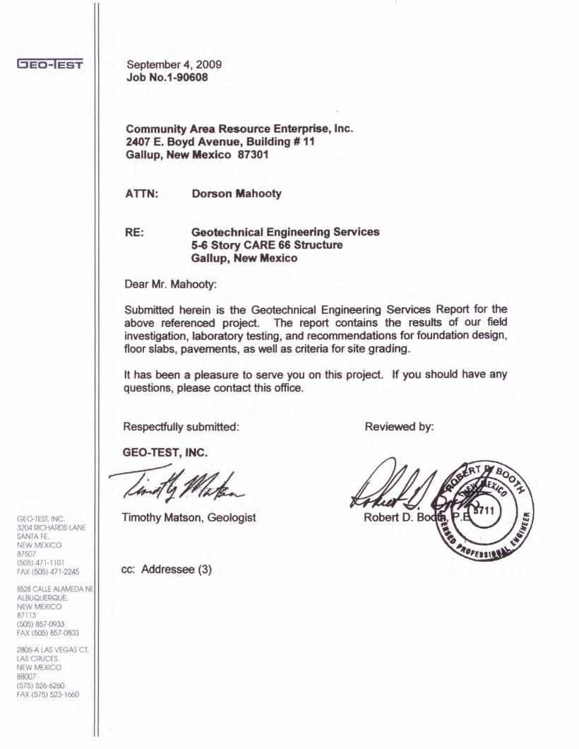
September 4, 2009Job No.1-90608
Community Area Resource Enterprise, Inc.2407 E. Boyd Avenue, Building # 11Gallup, New Mexico 87301
ATTN: Dorson Mahooty
RE: Geotechnical Engineering Services5..&Story CARE 66 StructureGallup, New Mexico
Dear Mr. Mahooty:
Submitted herein is the Geotechnical Engineering Services Report for theabove referenced project. The report contains the results of our fieldinvestigation, laboratory testing, and recommendations for foundation design,floor slabs, pavements, as well as criteria for site grading.
It has been a pleasure to serve you on this project. If you should have anyquestions, please contact this office.
Respectfully submitted: Reviewed by:
GEO-TEST, INC.
~A~~'~'", . / .... .
r:: ... .~. '.' .-' ,....,-.'. ..". .
Timothy Matson, Geologist Robert D: 8
cc: Addressee (3)

BED-lEST
GEO-TEST, INC.3204 RICHARDS LANESANTA FE,NEW MEXICO87507(505) 471-1101FAX (505) 471-2245
8528 CALLE ALAMEDA NEALBUQUERQUE,NEW MEXICO87113(505) 857-0933FAX (505) 857-0803
2805-A LAS VEGAS CT.LAS CRUCES,NEW MEXICO88007(575) 526-6260FAX (575) 523-1660
TABLE OF CONTENTS
INTRODUCTION 1
PROPOSED CONSTRUCTION 1
FIELD EXPLORATION 1
LABORATORY TESTING 2
SITE CONDITIONS 2
SUBSURFACE SOIL / ROCK CONDITIONS 2
CONCLUSIONS AND RECOMMENDATIONS 3
FOUNDATIONS 4
DRILLED PiERS 5
LATERAL LOADS 6
RETAINING WALLS 6
SLABS ON GRADE 6
SiTE-GRADING 7
PAVEMENT SECTION DESIGN 9
EXCAVATIONS 9
MOISTURE PROTECTION 10
FOUNDATION REVIEW AND INSPECTION 10
CLOSURE 11
BORING LOCATION MAP 13
BORING LOGS 14
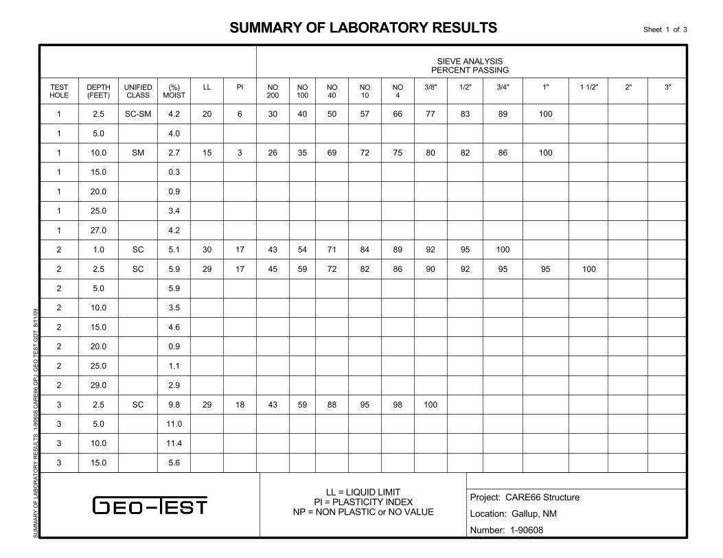
SUMMARY OF LABORATORY RESULTS 16
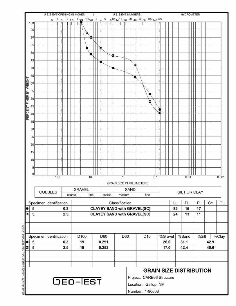
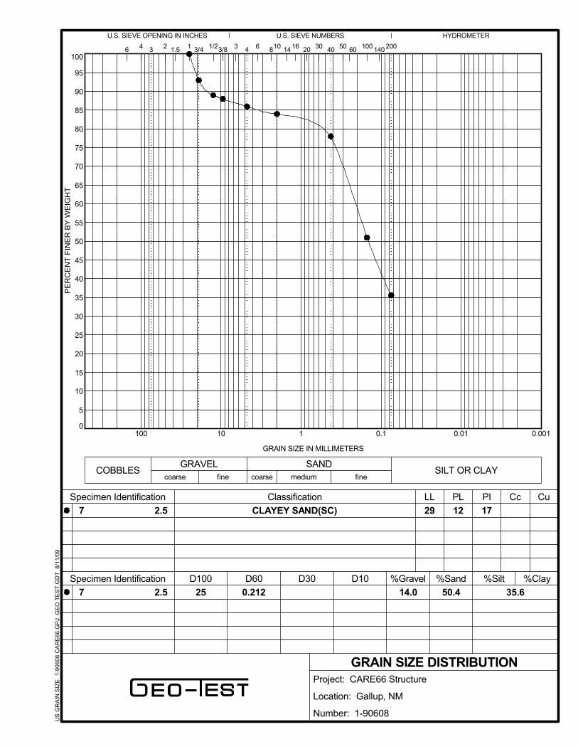
GRAIN SIZE DiSTRIBUTION 18
BEO-IEST
GEO-TESIINC.3204 RICHARDS LANESANTA FE,NEW MEXICO87507(505) 471-1101FAX (505) 471-2245
8528 CALLE ALAMEDA NEALBUQUERQUE,NEW MEXICO87113(505) 857-0933FAX (505) 857-0803
2805-A LAS VEGAS ctLAS CRUCES,NEW MEXICO88007(575) 526-6260FAX (575) 523-1660
5-6 Story CARE 66 StructureJob No. 1-90608
Page 1September 4, 2009
INTRODUCTION
This report presents the results of the geotechnical investigation performedby this firm for the proposed CARE 66 structure to be located on thenortheast corner of Puerco Street and Coal Avenue in Gallup, New Mexico,
The objectives of this investigation were to:
1) Evaluate the nature and engineering properties of thesubsurface soils and rock underlying the site,
2) Provide recommendations for foundation design, slab support,pavements, as well as criteria for site grading,
The investigation includes subsurface exploration, selected soil and rocksampling, laboratory testing of the samples, performing an engineeringanalysis and preparation of this report.
PROPOSED CONSTRUCTION
It is understood that the project consists of a 3-4 story steel or wood framedstructure on top of a 2-story, cast-in-place or precast concrete parkingstructure. No basements are proposed and the ground floor will be aconcrete slab on-grade. Structural loads have not been determined at thistime; however, for purposes of this report, it is assumed that foundation loadswill be moderate, not exceeding about 6 kips per lineal foot on bearing wallsand 250 kips on columns.
Should structural loads or other project details vary significantly from thoseoutlined above, this firm should be notified for review and possible revision ofrecommendations contained herein.
FIELD EXPLORATION
Seven exploratory borings were drilled to auger refusal at depths rangingfrom approximately 7 feet to 30 feet below existing grade. Locations of theborings are shown on the attached Boring Location Map. The soils and rockencountered in the borings were continuously examined, visually classifiedand logged during the drilling operation. The boring logs are presented in afollowing section of this report. Drilling was accomplished using a truckmounted drill rig equipped with 5-inch diameter continuous flight hollow stemauger. Subsurface materials were sampled at five foot intervals or less
Copyright© 2009, GEO- TEST, INC.
BEO-IEST
GEO- TEST.INC.3204 RICHARDS LANESANTA FE.NEW MEXICO87507(505) 471-1101FAX (505) 471-2245
8528 CALLE ALAMEDA NEALBUQUERQUE.NEW MEXICO87113(505) 857-D933FAX (505) 857-0803
2805-A LAS VEGAS CT.LAS CRUCES.NEW MEXICO88007(575) 526-6260FAX (575) 523-1660
5-6 Story CARE 66 StructureJob No. 1-90608
Page 2September 4, 2009
utilizing an open tube split barrel sampler or a ring-lined sampler driven by astandard penetration test hammer.
LABORATORY TESTING
Selected samples were tested in the laboratory to determine certainengineering properties of the soils and rock. Moisture contents weredetermined to evaluate the various soil and rock deposits with depth. Theresults of these tests are shown on the boring logs.
Sieve analysis and Atterberg limits tests were performed to aid in soilclassification. In addition, a consolidation test was performed on a selectedsample to evaluate the volume change characteristics of the soil uponincreased loading and moisture. The results of these tests are presented inthe Summary of Laboratory Results and on the individual test reportspresented in a following section of this report.
SITE CONDITIONS
A brief surface reconnaissance was performed during our site exploration.The site consists of an approximate 0.6 acre parcel of vacant land withapproximately 4 feet of vertical relief across the building site, slopinggenerally downward fro east to west. The entire lot appears to have beencut into the old hillside and stone retaining walls are present along thewestern and southwest corner of the parcel. Some undocumented fill maybe present and small pieces of trash and concrete debris are scatteredacross the surface. It is understood that a structure once stood on the lowerlevel, presumably back in the 1930's.
The site is bordered by an alley and commercial structures to the north,commercial and residential structures to the east, Coal Avenue to the southand Puerco Street to the west. It is understood that the structures on theeast side of the site will remain in-place. These structures have experiencedsome type of settling or heave as large cracks were observed in throughoutthe exterior of the structures, sidewalk and pavement.
SUBSURFACE SOIL I ROCK CONDITIONS
As indicated by the exploratory boring, a surface layer consisting primarily ofclayey sands with lesser amounts of sandy clays is present underlying thesite and extends to depths ranging from approximately 1/2 foot to as muchas 13 feet below existing site grades. These soils are generally of medium
Copyright© 2009, GEO- TEST, INC.
BEO-IEST
GEO-TESIINC.3204 RICHARDS LANESANTA FE.NEW MEXICO87507(505) 471-1101FAX (505) 471-2245
8528 CALLE ALAMEDA NEALBUQUERQUE.NEW MEXICO87113(505) 857-0933FAX (505) 857-0803
2805-A LAS VEGAS CT.LAS CRUCES.NEW MEXICO88007(575) 526-6260FAX (575) 523-1660
5-6 Story CARE 66 StructureJob No. 1-90608
Page 3September 4, 2009
plasticity and range from soft to very firm. Directly underlying the surficialsoil layer, sandstone bedrock was encountered and extended to full depthsexplored. The bedrock is relatively soft geologically but is hard from anengineering point of view and considered an excellent foundation material.
Soil moisture contents of the surficial soils and bedrock are generally low.Free water was encountered in boring no 4 at a depth of about 24 feet. It isbelieved that this is a thin perched layer, as no water was encountered in theremaining borings.
CONCLUSIONS AND RECOMMENDATIONS
Some of the near surface native soils underlying the site are of mediumplasticity and possess a low to medium expansive potential. Moreover,shallow sandstone bedrock is present underlying portions of the site and theuse of shallow spread-type footings bearing at uniform depths below finishedgrade could result in footings bearing on or very near the sandstone bedrockin some areas of the site and on the native soils in other areas which couldresult in excessive differential movements. In addition, manmade fill may bepresent underlying portions of the site.
Accordingly, in order to provide a uniform bearing surface for the newstructure, it is recommended that the existing soils and sandstone bedrockthroughout the building area be overexcavated to such an extent as toremove all existing manmade fill soils, or to provide for a minimum thicknessof 2 feet of structural fill beneath all footings and floor slabs, whichever is thegreater depth of overexcavation, and brought up to finished subgradeelevation with properly compacted structural fill. The new structure can thenbe supported on shallow spread-type footings and slab on-grade bearingdirectly on a minimum thickness of 2 feet of properly compacted, non-expansive structural fill.
As an alternate to shallow spread-type footings bearing on structural fill, thestructure could be supported on a series of straight, drilled, cast-in-placeconcrete piers socketed into the underlying sandstone bedrock. This type offoundation system would eliminate the need for overexcavation beneathfootings and, depending on the foundation loads involved could result inconsiderable savings in foundation costs. With this foundation alternate,concrete floor slabs should still bear on a minimum thickness of 2.0 feet ofproperly compacted, non-expansive structural fill.
Copyright© 2009, GED- TEST, INC.
BED-lEST
GEO-TEST. INC.3204 RICHARDS LANESANTA FE,NEW MEXICO87507(505) 471-1101FAX (505) 471-2245
8528 CALLE ALAMEDA NEALBUQUERQUE,NEW MEXICO87113(505) 857-0933FAX (505) 857-0803
2805-A LAS VEGAS CT.LAS CRUCES,NEW MEXICO88007(575) 526-6260FAX (575) 523-1660
5-6 Story CARE 66 StructureJob No. 1-90608
Page 4September 4, 2009
Detailed recommendations concerning the required site preparation and forboth alternates for foundation design are presented in the following sectionsof this report.
Careful moisture protection of the supporting soils is considered essential forthe satisfactory performance of the structure, regardless of the foundationsystem used. Accordingly, moisture protection is an important designconsideration and should be reflected in overall site grading and drainagedetails as recommended in the Moisture Protection section of this report.
FOUNDATIONS
Spread-Type Footings
It is recommended that the structure be supported on shallow spread-type footings and slabs on-grade bearing directly on a minimumthickness of 2.0 feet of non-expansive, relatively impermeable structuralfill. An allowable soil bearing pressure of 2,500 pounds per square footis recommended for the design of footings bearing directly on thestructural fill. This bearing value applies to full dead load plus realisticlive loads and can be safely increased by one-third for total loadsincluding wind and seismic forces.
In order to minimize the sensitivity of the structure to differentialmovement, footings and stem walls should be reinforced to allow for adegree of load redistribution should a localized zone of supporting soilsbecome wetted. Stem walls should either be positively separated fromfloor slabs or reinforced to minimize cracking at the slab/stem wallinterface.
Exterior footings should be established a minimum of 2.5 feet below thelowest adjacent grade, while interior footings should be at least 12inches below finished floor grade. The minimum recommended width ofsquare and continuous footings is 2.0 feet and 1.33 feet, respectively.
Maximum settlements of foundations designed and constructed asrecommended herein are estimated not to exceed % inch for the soilmoisture contents encountered during this investigation or moisturecontents introduced during construction. Differential movements shouldbe less than 75 percent of total movements. Significant moistureincreases in the supporting soils and bedrock after construction wouldcause additional movements and could create excessive movements, at
Copyright© 2009, GEO- TEST, INC.

bEO-IEST
GEO-TEST.INC.3204 RICHARDS LANESANTA FE.NEW MEXICO87507(505) 471-1101FAX (505) 471-2245
8528 CALLE ALAMEDA NEALBUQUERQUE.NEW MEXICO87113(505) 857-0933FAX (505) 857-0803
2805-A LAS VEGAS CT.LAS CRUCES.NEW MEXICO88007(575) 526-6260FAX (575) 523-1660
5-6 Story CARE 66 StructureJob No. 1-90608
Page 5September 4, 2009
least in some areas of the site. Thus, the moisture protection procedurespresented in a following section of the report are considered essential forthe satisfactory performance of the structure.
DRILLED PIERS
As an alternate to shallow spread-type footings bearing on structural fill,a series of straight, drilled, cast-in-place concrete piers extending aminimum of 5 feet into the underlying sandstone bedrock can be usedfor the support of the structure. The piers should be designed for an endbearing pressure of 15,000 psf and a side shear of 1,500 psf for thatportion of the pier penetrating the sandstone bedrock.
The following criteria should be utilized in the installation of a straightdrilled cast-in-place system:
1) Pier excavations should be drilled to such a depth as toachieve a minimum of 5 feet of penetration into the underlyingsandstone bedrock.
2) Pier excavations should be drilled or bored in such a manneras to provide a full size excavation.
3) Difficult excavation into the sandstone bedrock should beanticipated, and, thus, heavy duty equipment with special bitsor teeth and extra effort may be required.
4) The drilled pier excavations should be observed by arepresentative of this firm to verify proper diameter, depth,bearing conditions, reinforcement, and concrete placement.
5) Concrete placed freefall should not be allowed to contactreinforcing steel or the sides of the excavation.
6) Concrete should have an ultimate compressive strength of notless than that provided by the specifications and be workableand plastic. A design slump of 4 to 6 inches should beachieved.
7) The upper 5 feet of concrete should be vibrated to provideconsolidation.
Copyright© 2009, GEO- TEST, INC.

BED-lEST
GEO-TESIINC.3204 RICHARDS LANESANTA FE,NEW MEXICO87507(505) 471-1101FAX (505) 471-2245
8528 CALLE ALAMEDA NEALBUQUERQUE,NEW MEXICO87113(505) 857-Q933FAX (505) 857-0803
2805-A LAS VEGAS CT.LAS CRUCES,NEW MEXICO88007(575) 526-6260FAX (575) 523-1660
5-6 Story CARE 66 StructureJob No. 1-90608
Page 6September 4, 2009
8) To provide proper end bearing, pier excavations should bemachine cleaned. Additional passes as needed should bemade by the drill rig and observation should be performed.
9) Pier excavations should not be allowed to stand open morethan 6 hours prior to placing concrete.
Settlement of pier foundations designed and constructed as recommendedherein are estimated not to exceed 1/2 inch. Differential movement shouldbe less than 75 percent of total movements.
LATERAL LOADS
Resistance to lateral forces will be provided by soil friction between the basefloor slabs and footings and the soil and by passive earth resistance. Acoefficient of friction of 0.40 should be used for computing the lateralresistance between bases of footings and slabs and the soil. With backfill asrecommended in the site grading section of this report, a passive soilresistance equivalent to a fluid weighing 325 pounds per cubic foot should beused for analysis.
RETAINING WALLS
Lateral pressure against any retaining walls on the project will depend upontheir degree of restraint. Walls which are restrained so as to limit movementat the top to less than 0.001 times the height of the wall should be designedfor an "at rest" earth pressure of 55 pounds per square foot per foot of depth.Walls free to move at the top should be designed using an "active" earthpressure equal to 35 pounds per square foot per foot of depth.
The recommended equivalent fluid pressures are applicable to a condition ofhorizontal backfill without surcharge loads. Analysis of earth pressuresproduced by sloping backfill or surcharge loads can be provided by this firmupon request.
SLABS ON GRADE
Adequate support for slab-on-grade floors at the ground floor level will beprovided by the structural fill. Thus, the use of granular base for structuralsupport of floor slabs is not considered necessary. However, should it bedesired as a working surface, a course of granular base can be placedbeneath concrete floor slabs.
Copyright© 2009, GEO- TEST, INC.
BED-lEST
GEO-TEST. INC.3204 RICHARDS LANESANTA FE,NEW MEXICO87507(505) 471-1101FAX (505) 471-2245
8528 CALLE ALAMEDA NEALBUQUERQUE,NEW MEXICO87113(505) 857-D933FAX (505) 857-0803
2805-A LAS VEGAS CT.LAS CRUCES,NEW MEXICO88007(575) 526-6260FAX (575) 523-1660
5-6 Story CARE 66 StructureJob No. 1-90608
Page 7September 4, 2009
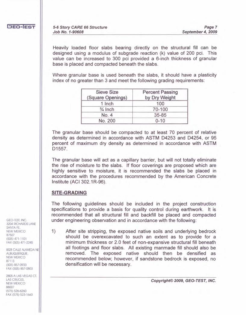
Heavily loaded floor slabs bearing directly on the structural fill can bedesigned using a modulus of subgrade reaction (k) value of 200 pci. Thisvalue can be increased to 300 pci provided a 6-inch thickness of granularbase is placed and compacted beneath the slabs,
Where granular base is used beneath the slabs, it should have a plasticityindex of no greater than 3 and meet the following grading requirements:
Sieve Size Percent Passing(Square Openinos) by Drv WeiQht
1 Inch 100% Inch 70-100No,4 35-85
No. 200 0-10
The granular base should be compacted to at least 70 percent of relativedensity as determined in accordance with ASTM 04253 and 04254, or 95percent of maximum dry density as determined in accordance with ASTM01557,
The granular base will act as a capillary barrier, but will not totally eliminatethe rise of moisture to the slabs. If floor coverings are proposed which arehighly sensitive to moisture, it is recommended the slabs be placed inaccordance with the procedures recommended by the American ConcreteInstitute (ACI 302.1 R-96).
SITE-GRADING
The following guidelines should be included in the project constructionspecifications to provide a basis for quality control during earthwork. It isrecommended that all structural fill and backfill be placed and compactedunder engineering observation and in accordance with the following:
1) After site stripping, the exposed native soils and underlying bedrockshould be overexcavated to such an extent as to provide for aminimum thickness or 2.0 feet of non-expansive structural fill beneathall footings and floor slabs. All existing manmade fill should also beremoved. The exposed native should then be densified asrecommended below; however, if sandstone bedrock is exposed, nodensification will be necessary.
Copyright© 2009, GEO- TEST, INC.
BEO-IEST
GEO-TEST, INC.3204 RICHARDS LANESANTA FE.NEW MEXICO87507(505) 471-1101FAX (505) 471-2245
8528 CALLE ALAMEDA NEALBUQUERQUE.NEW MEXICO87113(505) 857-0933FAX (505) 857--0803
2805-A LAS VEGAS CT.LAS CRUCES.NEW MEXICO88007(575) 526-6260FAX (575) 523-1660
5-6 Story CARE 66 StructureJob No. 1-90608
Page 8September 4, 2009
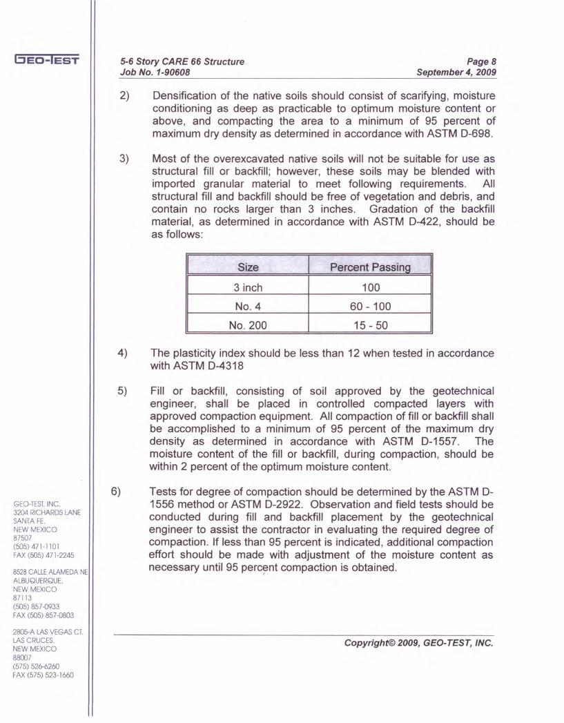
2) Oensification of the native soils should consist of scarifying, moistureconditioning as deep as practicable to optimum moisture content orabove, and compacting the area to a minimum of 95 percent ofmaximum dry density as determined in accordance with ASTM 0-698.
3) Most of the overexcavated native soils will not be suitable for use asstructural fill or backfill; however, these soils may be blended withimported granular material to meet following requirements. Allstructural fill and backfill should be free of vegetation and debris, andcontain no rocks larger than 3 inches. Gradation of the backfillmaterial, as determined in accordance with ASTM 0-422, should beas follows:
I Size I Percent Passing I3 inch 100
NO.4 60 - 100
No. 200 15 - 50
4) The plasticity index should be less than 12 when tested in accordancewith ASTM 0-4318
5) Fill or backfill, consisting of soil approved by the geotechnicalengineer, shall be placed in controlled compacted layers withapproved compaction equipment. All compaction of fill or backfill shallbe accomplished to a minimum of 95 percent of the maximum drydensity as determined in accordance with ASTM 0-1557. Themoisture content of the fill or backfill, during compaction, should bewithin 2 percent of the optimum moisture content.
6) Tests for degree of compaction should be determined by the ASTM 0-1556 method or ASTM 0-2922. Observation and field tests should beconducted during fill and backfill placement by the geotechnicalengineer to assist the contractor in evaluating the required degree ofcompaction. If less than 95 percent is indicated, additional compactioneffort should be made with adjustment of the moisture content asnecessary until 95 percent compaction is obtained.
Copyright© 2009, GEO- TEST, INC.

bED-lEST
GEO-TEST, INC.3204 RICHARDS LANESANTA FE,NEW MEXICO87507(505) 471-1101FAX (505) 471-2245
8528 CALLE ALAMEDA NEALBUQUERQUE,NEW MEXICO87113(505) 857--0933FAX (505) 857-0803
2805-A LAS VEGAS CT.LAS CRUCES,NEW MEXICO88007(575) 526-6260FAX (575) 523-1660
5-6 Story CARE 66 StructureJob No. 1-90608
Page 9September 4, 2009
PAVEMENT SECTION DESIGN
Based on the results of laboratory testing and analysis performed inaccordance with publications prepared by the Asphalt Institute, a minimumasphaltic pavement section of 3.0 inches of asphaltic concrete over 6.0inches of aggregate base course over 12 inches of compacted, nativesubgrade is recommended for parking lot and drive lane pavements. Prior toplacing the base course, the subgrade should be scarified to a depth of 8inches, moisture conditioned and properly compacted as recommended in aprevious section of this report. The recommended pavement section appliesto automobile parking and drive lanes only. Areas subjected to heavy traffic,including delivery trucks and trash collection trucks, should have theasphaltic concrete sections thickened by 1 inch.
Portland cement concrete pavement can be used in areas subjected toheavy truck traffic, including delivery trucks (loading docks), and trashcollection trucks (dumpster access), as an alternative to asphaltic concretepaving. Portland cement concrete pavement should consist of a minimum of6 inches of Portland cement concrete placed over 8 inches of compactedsubgrade. The pavement should be constructed with load transfer jointsdesigned for heavy traffic.
Increases in the subgrade moisture content can weaken the subgrade soils,thereby shortening pavement life and causing localized failure. Therefore, allpaved areas should be designed to drain completely and allow no ponding.Pavement materials should conform to materials as specified in the NewMexico Department of Transportation Standard Specifications for Road andBridge Construction. All native subgrade soils should be compacted to aminimum of 95 percent of the maximum dry density and must be at theoptimum moisture content to 2 percent above as determined in accordancewith ASTM 0-1557. All asphaltic pavements should be compacted tobetween 93 and 96 percent of the maximum Marshall density.
EXCAVATIONS
Excavation of the surficial soils can be made with the use of normal earthmoving equipment. Excavations extending into the underlying sandstonebedrock will likely be somewhat difficult and may require the use of hoe ramsor jack-hammers. However, it is not anticipated that any blasting will benecessary. Excavation side slopes in the surficial soils should be made nosteeper than 1.5 to 1 (horizontal to vertical). Side slopes of excavation intothe sandstone bedrock can be made vertically.
Copyright© 2009, GEO-TEST, INC.

bED-lEST
GEO-TESIINC,3204 RICHARDS LANESANTA FE,NEW MEXICO87507(505) 471-110 1FAX (505) 471-2245
8528 CALLE ALAMEDA NEALBUQUERQUE,NEW MEXICO87113(505) 857-0933FAX (505) 857-0803
2805-A LAS VEGAS CT.LAS CRUCES,NEW MEXICO88007(575) 526-6260FAX (575) 523-1660
5-6 Story CARE 66 StructureJob No. 1-90608
Page 10September 4, 2009
In any case, excavations should be made in accordance with CFR 29 Part1926 Subpart P, and other applicable state or local regulations.
MOISTURE PROTECTION
Precautions should be taken during and after construction to minimizemoisture increases of foundation soils and backfill behind retaining walls.Positive drainage should be established away from the structure and for adistance of at least 10 feet beyond its perimeter. A typical adequate slope is6 inches in the first 5 feet with positive drainage being provided from thosepoints to streets or natural water courses. Backfill should be well compactedand should meet the specifications outlined in the Site Grading section of thisreport. Irrigation within 5 feet of foundations should be carefully controlled.
Proper landscaping and drainage maintenance is required to precludeaccumulation of excessive moisture in the soils below the structure.Accumulations of excessive moisture would weaken the soils supporting thefoundations and slabs and can cause differential movement of foundationsresulting in cosmetic or structural damage to the structure.
The foregoing recommendations should only be considered minimumrequirements for overall site development. It is recommended that acivil/drainage engineer be consulted to provide more detailed grading anddrainage recommendations.
FOUNDATION REVIEW AND INSPECTION
This report has been prepared to aid in the evaluation of this site and toassist in the design of this project. It is recommended that the geotechnicalengineer be provided the opportunity to review the final design drawings andspecifications in order to evaluate whether the recommendations in thisreport are applicable to the final design. Review of the final design drawingsand specifications should be noted in writing by the geotechnical engineer.
Variations from soil conditions presented herein may be encountered duringconstruction of this project. In order to permit correlation between theconditions encountered during construction and to confirm recommendationspresented herein, it 'is recommended that the geotechnical engineer beretained to perform sufficient review during construction of this project.Observation and testing should be performed during construction to confirmthat suitable fill soils are placed upon competent materials and properlycompacted and foundation elements penetrate the recommended soils.
Copyright© 2009, GEO-TEST, INC.

BEO-IEST
GEO-TEST. INC.3204 RICHARDS LANESANTA FE,NEW MEXICO87507(505) 471-1101FAX (505) 471-2245
8528 CALLE ALAMEDA NEALBUQUERQUE,NEW MEXICO87113(505) 857-0933FAX (505) 857-0803
2805-A LAS VEGAS CT.LAS CRUCES,NEW MEXICO88007(575) 526-6260FAX (575) 523-1660
5-6 Story CARE 66 StructureJob No. 1-90608
Page 11September 4, 2009
CLOSURE
Our conclusions, recommendations and opinions presented herein are:
1) Based upon our evaluation and interpretation of the findings of thefield and laboratory program.
2) Based upon an interpolation of soil conditions between and beyondthe explorations.
3) Subject to confirmation of the conditions encountered duringconstruction.
4) Based upon the assumption that sufficient observation will beprovided during construction.
5) Prepared in accordance with generally accepted professionalgeotechnical engineering principles and practice.
This report has been prepared for the sole use of Community Area ResourceEnterprise, Inc., specifically for the design of the new Care 66 structure to beconstructed in Gallup, New Mexico, and not for the use by any third parties.
We make no other warranty, either express or implied. Any person using thisreport for bidding or construction purposes should perform such independentinvestigation as he deems necessary to satisfy himself as to the surface andsubsurface conditions to be encountered and the procedures to be used inthe performance of work on this project. If conditions are encountered duringconstruction that appears to be different than indicated by this report, thisoffice should be notified.
All soil samples will be discarded 60 days after the date of this report unlesswe receive a specific request to retain the samples for a longer period oftime.
Copyright© 2009, GEO-TEST, INC.


NO: 1 During Drilling: None After 24 Hours:
(jED-IESTProject:
Date:
Elevation:
CARE66 Structure
07/14/2009 Project No: 1-90608
Type: 5" 00 HSA
LOG OF TEST BORINGS GROUNDWATER DEPTH
f-aof-(f)LUf-
oLUo
SAMPLE SUBSURFACE PROFILE
I- >-u... I-
~...J U5 W (j)
w~ S 0::: z DESCRIPTION:J w N
I eto::: 0 I- 0 blows/ftI- w ...J eno, (9 :2W n, CO (5 >-c ow 0 «I- >- o:::u en0 ...J en~ I- Z ~* oE:, :J 20 40 60 80
~ .... _.1-_.-1-_.-"-_ . ..1_.-0~.: ..
_.L_.1.._.1-_ . .1_.
4 SC-SMSILTY CLAYEY SAND, SOME GRAVEL, I I I I
~.: .. >< SS 22-24-46 fine to coarse grained, low plasticity, hard, - ·1- .T - ·7-70 - .~ ..... 70 slightly moist, brown _.t--.t--.-t-.,_.
5- ZL.·.· >< 4 _.1--+_.+- -+_.SS -32-50/4 ' _~_1_~_ .L.
50/4" I I I I-T-T-T-,-
-"-·'--·T-'-·_.1-_.-1-_.-"-_ ..1- .
10 - ... SS SR 3_.L_.1.._.1-_ . .1_
I I I I_ .•..... -. __ .....•... _ .....•.. _.I I I I
_.t--.t--.-t-.,._._.1--.+-_.+_.-+_._.1..._.1_.+_.1_.
...0
I I I I15 - SS C-0-50/05" -T-T-T-,-
50/0.5" S NDSTO E SANDSTONE, slightly weathered, slightly -"-"-·T-·'-·fractured, thickly bedded, hard, red/gray _.1-_.-1-_.-"-_ ..1- .
... _.L_.1.._.1-_ . .1_.I I I I
_ . .1--.-<-_ .........._ ......•.-..... I I I I
20 - ..... SS SR 1 _.t--.t--.-t-.,.-. . - 1--.+-_.+_.-+_.
_.1..._.1_.~_.1_.I I I I
-T-T-T- ,--"-"-·T-·'-·
25 - SS SR 3 _.1-_.-1-_.-"-_ . ..1_.
_.L_.1.._.1-_ .1_ .I I I I
AC 4 _."'--_.""-_ •....•... _ ......•. _.AUGER REFUSAL ON BEDROCK AT 27' I I I I
NOTE: SR = Sampler refusal on Sandstone_.t--.t--.-t-.,._._.1--.+-_.+- -+_.
30 -_1..._1_+_1_
I I I I-T-T-T-,-_·,-·'--·T-·,-·_.1-_.-1-_.-"-_ . ..1_
- L_ 1.._.1-_ . .1_I I I I
35 - _."-_. __ ...•... - ~-
oza::o'"f-(f)LUf-u,ooo...J
LEGEND
SS - Split Spoon AMSL - Above Mean Sea LevelAC - Auger Cuttings CS - Continuous SamplerCAL - Modified California Sampler UD - Undisturbed
ST - Shelby TubeStratification lines represent approximate boundaries between soil types. Transitions may be gradual. Water level readingshave been made at times and under conditions stated. Fluctuations of groundwater may occur due to factors other than thosepresent at the time measurments were made.

BED-lEST
LOG OF TEST BORINGS
NO: 2
Project: CARE66 Structure
Date: 07/14/2009
Elevation:
Project No: 1-90608
Type: 5" OD HSA
GROUNDWATER DEPTH
During Drilling: None After 24 Hours:
SAMPLE
I- >-I-u,
W U5[ ....J U5w:gi ~ 0:: Z::::> wI ~o:: 0 I- 0I- W ....J ena. <.!J ::2;w a. OJ 6 >-c ow 0 «I- >- 0::0 en
0 ....J en~ I- z ~* 0,9; ::::>
~UD 0-0-12/6'
5 SC
..... SS 12/6" 6SR
5- SS SR 6
4
SUBSURFACEPROFILE
20 40 60 80T T T
_.L_ ..L._.J._.-!_.
_.L_.l.._.J._ ...1_.I I I I_ ..•.... _. __ .__ . __ .I I I I
I- -'r _.t- _. + _.-t -.t--+-+_.+_.-t-.t--L_+-_.+_.-1.-
I I I It--T-T-T-',-'I--·j--;--·i--·i-·I--.L- ..L.-J.--!-.1-_.L_.l.._.J._ ...1_.
I I I I_ ..•.... _._-. __ .__ .I I I I
-·r-·t--·-t-·-t-·-+-+_.+_.-t-.-.1- _.+- _. .L -.-1. -.
I I I I-T-T-'T-',-'
. .-T-T-'T-',-'_.L_ ..L._.J._.-!_.
_.L_.l.._.J._ ...1_.I I I I_ ..•.... _. __ ...•.. _. __ .I I I I
-·r-·t--·-t-·-t-·
-+-+_.+_.-t-.t--1--+--+--1.-
I I I It--T-T-'T-',-'t--j--';--'i--i-r-·L- ..L.-J.-.-!-.r_·L_.l.._.J._ ...1_.
I I I I_ ..•.... _. __ .__ .__ .I I I I
-·r-·t--·-t-·-t-·1----1------------------+ -+- +_.+ _. -t _.
o 30 - AUGER REFUSAL ON BEDROCK AT 29' I I I I~ NOTE: SR=Samplerrefusal'on -1-'1-'1-'1-g Sandstone -T-T-'T-',-'t; -T-T-'T-',-W -.L- ..L._.J._.-!_.I-
l5 _.L_.l.._.J._ ...1_.I I I I
(!) 35 - -.--.~-.--.~-.gL- __ L__~_~ __ ....JL__ ....JL__ ....JL__ ~ __ ~ L_ ~
5
3
S NDSTO E SANDSTONE, slightly weathered, slightlyfractured, thickly bedded, hard, red/gray
DESCRIPTIONN
blows/ft
CLAYEY SAND, fine to medium grained,medium plasticity, soft, slightly moist, brown
10 - :. SS SR
LEGENDSS - Split Spoon AMSL - Above Mean Sea LevelAC - Auger Cuttings CS - Continuous SamplerCAL - Modified California Sampler UD - Undisturbed
ST - Shelby TubeStratification lines represent approximate boundaries between soil types, Transitions may be gradual. Water level readingshave been made at times and under conditions stated. Fluctuations of groundwater may occur due to factors other than thosepresent at the time measurments were made.
15 - SS SR
l-coI-(f)WI-
oWo
20 - SS SR
25 -:: SS SR
AC

BED-lEST
LOG OF TEST BORINGS
NO: 3
Project:
Date:
Elevation:
CARE66 Structure
07/14/2009 Project No: 1-90608
Type: 5" 00 HSA
GROUNDWATER DEPTH
During Drilling: None After 24 Hours:
SAMPLE
I- >-l-u,
LU U)ens 0:: z:::> LU0 I- 0
LU -l (f) >-c 00.. co 0>- 0::0 (f)I- Z :2~ 0.3: :::> 20 40 60 80
[II-0..LUo
C)o-l
SUBSURFACE PROFILE
DESCRIPTIONN
blows/ft
-,c,oswa:<!o
~oz12o'"f-'"Wf-U.ooo~L- __ --l L- __ ~ -l- -l- -l- ~ ~ ~ ~
f-aof-
'"Wf-oWo
25 -
30 -
35 -
LEGEND
SS - Split Spoon AMSL - Above Mean Sea LevelAC - Auger Cuttings CS - Continuous SamplerCAL - Modified California Sampler UD - Undisturbed
ST - Shelby TubeStratification lines represent approximate boundaries between soil types. Transitions may be gradual. Water level readingshave been made at times and under conditions stated. Fluctuations of groundwater may occur due to factors other than thosepresent at the time measurments were made.
BEO-IEST
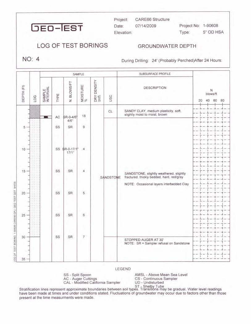
NO: 4
LOG OF TEST BORINGS
Project: CARE66 Structure
Date: 07/14/2009
Elevation:
Project No: 1-90608
Type: 5" 00 HSA
GROUNDWATER DEPTH
During Drilling: 24' (Probably Perched)After 24 Hours:
SAMPLE
r- >-u, r-
en UJ u;~
0:: Z:J UJ0 r- 0....J C/) >-c uco 6 o::u C/)z ~~ 0.30 :J
CL
[ ....JUJ<X:
I ....J>r- Cl.0:: UJo, o ~UJ n,UJ 0 <x:r- >-0 ....J C/)~ r-
r-o(9r-ooLUr-aLU(9
5 -::
10- ::
15 -
20 - ••
w- AC pR-0-4/64/6"
SS SR
SS R-0-17/1"17/1 "
SS SR
SS SR
SANDSTONE, slightly weathered, slightlySf NDSTO ~E fractured, thickly bedded, hard, red/gray
NOTE: Occasional layers interbedded Clay
18
20 40 60 80
~a.(9
:8LU~<:o
i(9z12a<Dr-ooLUr-LLa(9a~L-__~~ __~ __~ ....J- ....J- ....J- ~ ~ ~~ ~35 -
25 -::
30 -+~'-4
SS SR
SS SR
9
4
4
5
6
7
SUBSURFACE PROFILE
DESCRIPTIONN
blows/ft
LEGEND
SS - Split Spoon AMSL - Above Mean Sea LevelAC - Auger Cuttings CS - Continuous SamplerCAL - Modified California Sampler UD - Undisturbed
ST - Shelby TubeStratification lines represent approximate boundaries between soil types. Transitions may be gradual. Water level readingshave been made at times and under conditions stated. Fluctuations of groundwater may occur due to factors other than thosepresent at the time measurments were made.
SANDY CLAY, medium plasticity, soft,slightly moist to moist, brown
STOPPED AUGER AT 30'NOTE: SR = Sampler refusal on Sandstone
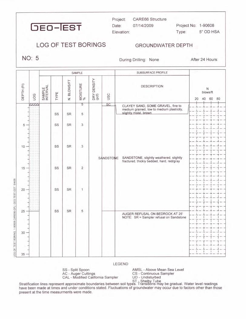
NO: 5 During Drilling: None After 24 Hours:
BEO-IESTProject:
Date:
Elevation:
CARE66 Structure
07/14/2009 Project No: 1-90608
Type: 5" OD HSA
LOG OF TEST BORINGS GROUNDWATER DEPTH
~t-oot-enUJt-
oUJo
SAMPLE SUBSURFACEPROFILE
f- >-u, f-
~--l en UJ en
UJ« S c::: z DESCRIPTION--l> :::J UJ NJ: a..C::: 0 f- 0 blows/ftf- UJ --l eno, o :2UJ n, rn (5 >-c U
UJ 0 «f- >- c:::u en0 --l en~ f- z :2~ 0.3 :::J 20 40 60 80
~ 5 ~( CLAYEY SAND, SOME GRAVEL, fine toI I I
\ medium grained, low to medium plasticity,r--I--L-.-L_.-!-
.... "Iinhthl ~nid hr~wn'- _.L _ . .1-_ .-L_.-!_.
..... SS SR 5 I I I I
.... . ,-_. __ .--.- _. __ .
..... I I I I
... . '-_.r _.+ _. + _.-t _ .
5-: .... SS SR 3 '--+ --+ _.+ _.+_...... '-- L_.t-_.-!-_-t-
... I I I I'-- r-r-'T-',-.... '-- r-r-'T-',-'..... '- -.1- -.L - .-L-.-!- .... .
10 -: SS SR 3,-_.L_ . .I-_ . .1._ . ..1_.
.... I I I I-_. __ . __ . __ .__ .
..... I I I I-_.r _.+ _. + _.-t _.....
Sf NDSTO JE SANDSTONE, slightly weathered, slightly... . -- +- -+ _. + _.+ _ .... . fractured, thickly bedded, hard, red/gray..... --.1-- ..t---!--.-t-.... ... I I I I
15 - .. . SS SR 2 --T-r-'T-',--_·j--·i---j--·i-·
.. .__ .I-_.L_.-L_.-!_ .__ .L_ ..I-_ . .1._ . ..1_.
.... I I I I-_. __ . __ .__ .__ .
..... I I I I20 -: .... SS SR 1 - -'r -'r - .-t-.-t-.
... . --t--t--.-t---t- ..... --1--.t--.-!---t-
..... I I I I
..... '--T-r-'T-',-'
..... '--'j--r-'T-',-25
.... .SS SR 5 _.I-_.L_.-L_.-!_.
AUGER REFUSAL ON BEDROCK AT 25' '-- L_ ..I-_ . .1._ . ..1_.NOTE: SR = Sampler refusal on Sandstone I I I I'-- oA...._. __ ....•..._. __ .
I I I I~-'r -'r _.-t-.-t-.~-.t--.t---t--.-t-
30 - ~-1--.t---!--.-t-'-- I I I I
r-r-'T-,-'--j--·i--·-j--·i-·'-_.1- -.L_.-L_.-! _.,-_.L_ ..I-_ . .1._ . ..1_.
I I I I35 - ~-.--.--.--.--.
ozii:o<IIt-enUJt-u,ooo...J
LEGEND
SS - Split Spoon AMSL - Above Mean Sea LevelAC - Auger Cuttings CS - Continuous SamplerCAL - Modified California Sampler UD - Undisturbed
ST - Shelby TubeStratification lines represent approximate boundaries between soil types. Transitions may be gradual. Water level readingshave been made at times and under conditions stated. Fluctuations of groundwater may occur due to factors other than thosepresent at the time measurments were made.

(jED-IEST
LOG OF TEST BORINGS
NO: 6
Project: CARE66 Structure
Date: 07/14/2009
Elevation:
Project No: 1-90608
Type: 5" OD HSA
GROUNDWATER DEPTH
During Drilling: None After 24 Hours:
m
~m
5of-enwf-
owo
~-l
lJ.Je:(I -l>f- a..tl:: lJ.Jc, <.9 ~lJ.J n,lJ.J 0 e:(f- >-0 -l CJ)~ f-
ESS
5 - :.
10 -
15 -
20 -
SS
SS
SS
SS
SAMPLE
SR
10
6
>-f-Ci)ZlJ.Jo>-ctl::uo~
oCJ)::l
Nblows/ft
CL-SC SANDY CLAY/CLAYEY SAND, low to r--.L- ..L.-.,!,-.4-~_--+_-.JrnITl.el"ri:1i.i·"um.rn.llla.s1il:· ;it. ~<::iOft.nft....::<::ili:llii"~htl~v.rru;moist;Ltbl[ID!rowm..-n-l-_. L _ . .L _ . .1_ ...1_.
I I I If--,-'I-',-,-'>-- _.t- _.t- -. + _.-t _.
-+-+_.+_.-+_.-1--.\--.-!--.-1--.
I I I I-T-T-·T-·""-·-T-T-'T-',-'_.L- ..L.-.,!,_.4_.
_.L_ ..L_ ..1_ ...1_.I I I I_ ..•.... _ ...•... _ ...-._. __ .I I I I
_.t--.t- - .-t-.-t-.
-+-+_.+_.-+-._.1-- ..\-_.-!---1--
I I I I-T-T-·T-·""-·-T-T-'T-',-'_.L- ..L._.,!,_.4_.
_.L_ ..L_ ..1_ ...1_.I I I Ir--"l-'I-',-',-'
r- _.t- _. + _. + _.-t _.f--+-+_.+_.-+_.>--_L_.\-_.-!-_.-1--
I I I I>---T-T-·T-·""-·
a: f--i--;--'i--'i-'~ 25 - 3 l- - .L - . .L. - . .L- .4 - .~ _.L_ ..L_ . .1_ ...1_.
« ~ 3 1---1-----------------+ I I I I~ AUGER REFUSAL ON BEDROCK AT 27' - T " '1-"-"-'m
§, -.t--.t--.-t-.-t-.NOTE: SR = Sampler refusal on Sandstone _. t- _. +- _ . + _ .-+ _.
l? 30 - - .1- - . .\- _ . -!- _ . -1- -~ -+-+-+--}-mf- -T-T-'T-',-'~ -.J....-.J...- . ..L._ . ...J._.f- . . . .~ _.L_ ..L_ ..1_ ...1_.
I I I Il? 35 - _. __ .__ .__ .__ .gL- L__4__~ __ _L__ _L__ _L__ ~ __ 4_ L_ ~
SUBSURFACEPROFILE
DESCRIPTION
20 40 60 80
SR 5
2SI NDSTO ~E SANDSTONE, slightly weathered, slightly
fractured, thickly bedded, hard, red/gray
LEGEND
SS - Split Spoon AMSL - Above Mean Sea LevelAC - Auger Cuttings CS - Continuous SamplerCAL - Modified California Sampler UD - Undisturbed
ST - Shelby TubeStratification lines represent approximate boundaries between soil types. Transitions may be gradual. Water level readingshave been made at times and under conditions stated. Fluctuations of groundwater may occur due to factors other than thosepresent at the time measurments were made.
SR 3
SR
SR

LOG OF TEST BORINGS
NO: 7
Project:
Date:
Elevation:
CARE66 Structure
07/14/2009 Project No: 1-90608
Type: 5" 00 HSA
GROUNDWATER DEPTH
During Drilling: None After 24 Hours:
SAMPLE
t- >-u, t-
~...J U5 LlJ Vi
LlJ;; S a::: z:::l LlJI CL'a::: 0 t- ot- LlJ ...J (j)o, o ;2LlJ c, III 0 >-c ULlJ 0 «t- >- :i a:::u (j)
0 ...J (j)~ t- ~* oS :::l
CLAYEY SAND, SOME GRAVEL, fine tomedium grained, medium plasticity, veryfirm, slightly moist, brown
10 -
SUBSURFACE PROFILE
20 40 60 80
~a.C)
$wcr«u
~C)z12aCDf-CI)wf-u,aC)a~L-__~L- __~ __~ -L -L -L ~ ~ L- ~
V~·'~.. ~
5. ,/. ....'1><~ r- : SS 17-18-2Ef.Z ..... 44
5~'~" .r>< 5
SS 10-17-2~.,/ '. 42 5
15 -
f-aC)
~Wf-
awC)
20 -
DESCRIPTIONN
blows/ft
25 -
30 -
35 -
I 1-.l-- ..j...-.J.._ . ..!_.
_.L_ ..L_ ..l_ ..l_ .I I 1 I~.~~.~~~.~~.I I I It------I--------------------------------+ - T- T- .T - ',-'
AUGER REFUSAL ON SANDSTONE AT 7' -', -'T - 'T-',-'-.l-- ..j...-.J..- . ..!_.
_.L_ ..L_ ..l_ ..l_.I I I I_ ..•.... _. __ ...•._. __ .I I I I
I- _.t- _.t- _. + _. + _.I- - -+- - -+- _.+ _. -+ _.1--'!--'.1--~--!.-.
I I I II--T-T-'T-',-'t- -'r- -'r- _.T _.-j- _.t--l-- ..j..._.J..- ...!-.
1-_.L_ ..L_ ..l_ ..l_.I I I I1--,-T-'7-,-
I- - .t-- .t--'i--.-t _.
I- - -+-- -+-_.+_.-+ _.t--!--.1--~--!.-
I I I If--T-T-'T-',-'t- -'r- -'r- - T _. -j- _.t--l-- ..j..._.J..- ...!-.
t-_.L_ ..L_ ..l_ ..l_.I I I I_ ..•.... _. __ .--_. __ .I I I I
_.t--.t--'i--.-t-.--+---+-_.+_.-+_.-.!-- ..1--.~-.-!.-.
I I I I-T-T-'T-',-'-T-T-'T-',-'-.l-- ..j..._.J.._ . ..!_.
_.L_ ..L_ ..l_ ..l_.I I I I
SC
LEGEND
SS - Split Spoon AMSL - Above Mean Sea LevelAC - Auger Cuttings CS - Continuous SamplerCAL - Modified California Sampler UD - Undisturbed
ST - Shelby TubeStratification lines represent approximate boundaries between soil types. Transitions may be gradual. Water level readingshave been made at times and under conditions stated. Fluctuations of groundwater may occur due to factors other than thosepresent at the time measurments were made.
17
2
1009592898471
3.4
43
5.9
305.1SC1.02
4.227.0
1
54
90
3.510.02
5.95.02
100952.5 92SC 86827259451729
25.0
95
57
1
4.05.01
1008983
1
66
2.7
5040306204.2SC-SM2.5 77
80
1
0.920.01
0.315.01
10010.0 82SM 7572693526315
4.6
86
SUMMARY OF LABORATORY RESULTS
2"
2
LL = LIQUID LIMITPI = PLASTICITY INDEX
NP = NON PLASTIC or NO VALUEProject: CARE66 Structure
Location: Gallup, NM
Number: 1-90608
SIEVE ANALYSISPERCENT PASSING
3"NO100
SU
MM
AR
Y O
F LA
BO
RA
TOR
Y R
ES
ULT
S 1
-906
08 C
AR
E66
.GP
J G
EO
TE
ST.
GD
T 8
/11/
09
TESTHOLE
DEPTH(FEET)
UNIFIEDCLASS
(%)MOIST
LL 1 1/2"NO200
1"NO40
NO10
NO4
3/8" 1/2" 3/4"PI
29.0
Sheet 1 of 3
594318299.8SC2.5 95
2.9
98
2
1.125.02
0.920.02
3
15.0
15.0
88
5.63
11.410.03
11.05.03
100

53
4
2.52.05
100837974
2.5
64
SC
4317325.2SC0.35
7.1
5
70
93
3
20.05
2.015.05
2.510.0
5 100
6.0
90837872484111245.0
5
63
30.0
4
8.55.04
1009997
SC-SM
84
4.3
50203517.6CL2.54
2.820.0
93
70
25.04
5.220.04
4.315.04
10.0 70
25.0
70706461532316719 100
Project: CARE66 Structure
Location: Gallup, NM
Number: 1-90608
2"
LL = LIQUID LIMITPI = PLASTICITY INDEX
NP = NON PLASTIC or NO VALUE
1 1/2"
SIEVE ANALYSISPERCENT PASSING
3"
Sheet 2 of 3
1.3
SUMMARY OF LABORATORY RESULTS
NO100
SU
MM
AR
Y O
F LA
BO
RA
TOR
Y R
ES
ULT
S 1
-906
08 C
AR
E66
.GP
J G
EO
TE
ST.
GD
T 8
/11/
09
TESTHOLE
DEPTH(FEET)
UNIFIEDCLASS
(%)MOIST
LL NO200
NO40
NO10
NO4
3/8" 1/2" 3/4" 1"PI
75
SC-SM2.56
100929292
19
86
7
625520389.8CL1.06
4.7
90
5.0
2.610.0
5.5
5.26
10096959086814436
6

4.8
88 89 93 100
7 5.0 4.5
84
7.0
78
6
7
3.0
15.0 2.2
6 20.0 1.0
6 25.0 2.5
86
27.0
7 2.5 SC 4.5 29 17 36 51
6
PI 3/4"1/2"3/8"NO4
NO10
NO40
1"NO200
1 1/2"LL(%)MOIST
UNIFIEDCLASS
DEPTH(FEET)
TESTHOLE
SU
MM
AR
Y O
F LA
BO
RA
TOR
Y R
ES
ULT
S 1
-906
08 C
AR
E66
.GP
J G
EO
TE
ST.
GD
T 8
/11/
09
NO100
Sheet 3 of 3
3"
SIEVE ANALYSISPERCENT PASSING
Project: CARE66 Structure
Location: Gallup, NM
Number: 1-90608
SUMMARY OF LABORATORY RESULTS
2"
LL = LIQUID LIMITPI = PLASTICITY INDEX
NP = NON PLASTIC or NO VALUE

2.6680.323
2525 0.102
10
25
60
0
5
10
20
30
35
40
45
50
15
65
55
0.0010.010.11
70
75
80
85
90
95
100
100
medium
11
LL PL Cu
D60
1.5
14
200HYDROMETERU.S. SIEVE OPENING IN INCHES U.S. SIEVE NUMBERS
SILTY SAND with GRAVEL(SM)
6
122015
30.126.0
D100
SILTY, CLAYEY SAND with GRAVEL(SC-SM)3
1/23/8
34.025.0
35.9
6
10.0
Project: CARE66 Structure
Location: Gallup, NM
Number: 1-90608
US
GR
AIN
SIZ
E 1
-906
08 C
AR
E66
.GP
J G
EO
TE
ST.
GD
T 8
/11/
09
49.0
810 143/4
Specimen Identification
60
Classification
50
2.5
Specimen Identification
3 100
coarse
PE
RC
EN
T FI
NE
R B
Y W
EIG
HT
GRAIN SIZE IN MILLIMETERS
%Gravel %Sand %Silt %Clay
1
fine
GRAIN SIZE DISTRIBUTION
COBBLESGRAVEL SAND
Cc
140
PI
1 10.0
16 20 30 4016
coarse
3 2
D10
2.5
fineSILT OR CLAY
4
D30
4

0.2170.163
1937.5
10
25
60
0
5
10
20
30
35
40
45
50
15
65
55
0.0010.010.11
70
75
80
85
90
95
100
100
22
LL PL
200
D60
1.5
12
HYDROMETERU.S. SIEVE OPENING IN INCHES U.S. SIEVE NUMBERS
CLAYEY SAND(SC) 13Cu
3029
43.244.8
D100
8
CLAYEY SAND(SC) 17
medium
1/23/8
11.014.0
45.8
17
2.5
Project: CARE66 Structure
Location: Gallup, NM
Number: 1-90608
US
GR
AIN
SIZ
E 1
-906
08 C
AR
E66
.GP
J G
EO
TE
ST.
GD
T 8
/11/
09
41.2
6010 143/4
Specimen Identification
6
Classification
50
1.0
Specimen Identification
%Gravel
140
coarse
3
PE
RC
EN
T FI
NE
R B
Y W
EIG
HT
%Sand %Silt %Clay
22
fineCOBBLES
GRAVEL SAND
PI
GRAIN SIZE DISTRIBUTION
3
GRAIN SIZE IN MILLIMETERS
Cc
10016 20 30 40
1.0
16
SILT OR CLAY
2
D10
4
2.5
coarse
4
D30
fine

200
9.5 0.155
30
100
95
90
85
80
75
70
65
60
55
50
45
35
25
20
15
10
5
0
40
100 10 1 0.1 0.01 0.001
D100
1.5
PLLL
3
medium
D60
6
43.4
29 11CLAYEY SAND(SC)
U.S. SIEVE NUMBERSU.S. SIEVE OPENING IN INCHES HYDROMETER
fine
60
Cu
US
GR
AIN
SIZ
E 1
-906
08 C
AR
E66
.GP
J G
EO
TE
ST.
GD
T 8
/11/
09
Project: CARE66 Structure
Location: Gallup, NM
Number: 1-90608
18
54.62.0
3/81/23/4
2.5
1 50
Classification
Specimen Identification
Specimen Identification
14108
GRAIN SIZE IN MILLIMETERS
%Clay%Silt%Sand%Gravel
3
coarse
6
PE
RC
EN
T FI
NE
R B
Y W
EIG
HT
140
GRAIN SIZE DISTRIBUTION
CcPI
SANDGRAVELCOBBLES
40302016
2.53
43 2
D10D30
fine coarseSILT OR CLAY
4 100

0.1281.648
12.537.5 0.191
100
30
65
0
5
10
15
25
35
40
45
50
55
20
70
60
0.0010.010.1110
75
80
85
90
95
100
44
LL PL
200
D60
1.5
12
HYDROMETERU.S. SIEVE OPENING IN INCHES U.S. SIEVE NUMBERS
SANDY LEAN CLAY(CL) 15Cu
3519
50.116.4
D100
8
SILTY, CLAYEY SAND with GRAVEL(SC-SM) 7
medium
1/23/8
3.036.0
46.9
20
10.0
Project: CARE66 Structure
Location: Gallup, NM
Number: 1-90608
US
GR
AIN
SIZ
E 1
-906
08 C
AR
E66
.GP
J G
EO
TE
ST.
GD
T 8
/11/
09
47.6
6010 143/4
Specimen Identification
6
Classification
50
2.5
Specimen Identification
%Gravel
140
coarse
3
PE
RC
EN
T FI
NE
R B
Y W
EIG
HT
%Sand %Silt %Clay
44
fineCOBBLES
GRAVEL SAND
PI
GRAIN SIZE DISTRIBUTION
3
GRAIN SIZE IN MILLIMETERS
Cc
10016 20 30 40
2.5
16
SILT OR CLAY
2
D10
4
10.0
coarse
4
D30
fine
0.2910.252
1919
200
30
0
5
10
15
25
35
40
45
50
55
60
20
75
65
0.0010.010.1110100
80
85
90
95
100
70
55
LL PL
fine
D60
1.5
13
HYDROMETERU.S. SIEVE OPENING IN INCHES U.S. SIEVE NUMBERS
CLAYEY SAND with GRAVEL(SC) 15Cu
3224
42.940.6
D100
8
CLAYEY SAND with GRAVEL(SC) 11
medium
1/23/8
26.017.0
31.1
17
2.5
Project: CARE66 Structure
Location: Gallup, NM
Number: 1-90608
US
GR
AIN
SIZ
E 1
-906
08 C
AR
E66
.GP
J G
EO
TE
ST.
GD
T 8
/11/
09
42.4
10 143/4
Specimen Identification
6
Classification
50
0.3
Specimen Identification
%Gravel
coarse
3
PE
RC
EN
T FI
NE
R B
Y W
EIG
HT
%Sand %Silt %Clay
55
100
COBBLESGRAVEL SAND
PI Cc
GRAIN SIZE IN MILLIMETERS
2
GRAIN SIZE DISTRIBUTION
14016 20 30 40
0.3
16 60
SILT OR CLAY
D10
4
2.5
coarse
34
D30
fine

0.1230.235
2519
200
100
25
0
5
10
20
30
35
40
45
50
55
15
70
60
0.0010.010.1110
75
80
85
90
95
65
100
66
LL PL
D60
1.5
12
HYDROMETERU.S. SIEVE OPENING IN INCHES U.S. SIEVE NUMBERS
SANDY LEAN CLAY(CL) 18Cu
3819
55.036.1
D100
8
SILTY, CLAYEY SAND(SC-SM) 7
medium
1/23/8
10.010.0
35.0
20
2.5
Project: CARE66 Structure
Location: Gallup, NM
Number: 1-90608
US
GR
AIN
SIZ
E 1
-906
08 C
AR
E66
.GP
J G
EO
TE
ST.
GD
T 8
/11/
09
53.9
6010 143/4
Specimen Identification
6
Classification
50
1.0
Specimen Identification
%Gravel
140
coarse
3
PE
RC
EN
T FI
NE
R B
Y W
EIG
HT
%Sand %Silt %Clay
66
fineCOBBLES
GRAVEL SAND
PI
GRAIN SIZE DISTRIBUTION
3
GRAIN SIZE IN MILLIMETERS
Cc
10016 20 30 40
1.0
16
SILT OR CLAY
2
D10
4
2.5
coarse
4
D30
fine
25 0.212
15
85
80
75
70
65
60
55
50
45
40
35
30
20
100
10
5
0
25
100 10 1 0.1 0.01 0.001
90
95
35.6
1.5
PLLL
7
Cu
200
D100
6
29 12CLAYEY SAND(SC)
U.S. SIEVE NUMBERSU.S. SIEVE OPENING IN INCHES HYDROMETER
fine
606
D60
50U
S G
RA
IN S
IZE
1-9
0608
CA
RE
66.G
PJ
GE
O T
ES
T.G
DT
8/1
1/09
Project: CARE66 Structure
Location: Gallup, NM
Number: 1-90608
17
50.414.0
3/81/23/4
Specimen Identification
810 14
2.5Specimen Identification
Classification
medium
%Sand%Gravel
3
coarse
PE
RC
EN
T FI
NE
R B
Y W
EIG
HT
%Clay
Cc
COBBLESGRAVEL
GRAIN SIZE IN MILLIMETERS
PI
GRAIN SIZE DISTRIBUTION
7
SAND
40302016
2.5
%SiltD10
100 1403 2
D30
4
fine coarseSILT OR CLAY
4 1

INITIAL MOISTURE CONTENT = 9.7 %118.6 PCFINITIAL DRY DENSITY =
BORING #2 @ 1'
CONSOLIDATION TEST RESULTS5-6 STORY CARE66 STRUCTURE
-3
-2
-1
0
1
2
3
4
5
6
7
8
9
10
0.1 1 10
APPLIED LOAD (KSF)
CO
NSO
LID
ATI
ON
- PE
RC
ENT
- SW
ELL
SAMPLE INUNDATED AT 0.144 KSF

Division 00 SECTION 00 42 00 Lump Sum Price Proposal Form

Division 00 SECTION 00 43 00 Bid Bond Form

REPLACE THIS PAGE WITH THE AMERICAN INSTITUTE OF ARCHITECTS BID BOND (AIA DOCUMENT A310)

Division 00 SECTION 00 43 13 Bid Security Form

THIS FORM MUST BE ATTACHED TO BOND BID SECURITY FORM Section 00 43 13 Review and Approval: This Bond has been executed by a Surety named in the current list of “Companies Holding Certificates of Authority as Acceptable Sureties on Federal Bonds and as Acceptable Reinsuring Companies,” as published in Circular 570 (amended) by the Audit Staff Bureau of Accounts, United States Treasury Department. Approved: ______________________________________________________ DATE: ____________________________________________________ Owner’s Representative or Governing Authority

Division 00 SECTION 00 43 36 Subcontractor’s Listing Form

SUBCONTRACTOR LISTING Section 00 43 36
The Contractor must list below the names and license numbers of all qualified Subcontractor’s or suppliers he will employ for the various portions of the work indicated. Failure on the part of the Contractor to complete or property complete this list will constitute sufficient grounds to reject his bid.
The Contractor may list himself to perform one or more of the listed categories of work for which he has any requisite state licenses when
required. In this case, all personnel performing such work at the site shall be carried on his own payroll, except that he may sublet those portions of the work which are traditionally and commonly sublet by the representative Subcontractor in the community. If equipment is leased with operators, the operators need not be carried on the Contractor’s payroll.
List only a single name for each listing. If a change occurs in the list, brought about by the exercising of any of the alternates involved in the Bid
Form, the Bidder must show this change on the list. If no name appears other than those listed under the base bid, adherence to those names will be required no matter which alternate, if any, is exercised.
Refer to the “Instructions to Bidders” for requirements relating to Navajo preference in subcontracting.
Adherence to this listing upon signing the Contract will be mandatory, except to the extent those changes are mandated by authorities of the
Navajo Nation in regard to preference in subcontracting.
The list, with names of companies filled-in, shall be submitted with the Bid. License numbers shall be updated by qualified bidders to Architect within 24 hours of owner’s request.
TRADE NAME ADDRESS TELEPHONE# LICENSE # SUBCONTRACTOR SIGNATURE - TO BE OBTAINED AFTER AWARD OF CONTRACT ___________________________________________________________________________________________ ___________________________________________________________________________________________ ___________________________________________________________________________________________ ___________________________________________________________________________________________ ___________________________________________________________________________________________ ___________________________________________________________________________________________ ___________________________________________________________________________________________

TRADE NAME ADDRESS TELEPHONE# LICENSE # SUBCONTRACTOR SIGNATURE - TO BE OBTAINED AFTER AWARD OF CONTRACT ___________________________________________________________________________________________ ___________________________________________________________________________________________ ___________________________________________________________________________________________ ___________________________________________________________________________________________ __________________________________________________________________________________________ ___________________________________________________________________________________________ ___________________________________________________________________________________________ ___________________________________________________________________________________________ ___________________________________________________________________________________________ ___________________________________________________________________________________________ ___________________________________________________________________________________________ ___________________________________________________________________________________________ ___________________________________________________________________________________________ ___________________________________________________________________________________________ ___________________________________________________________________________________________ ___________________________________________________________________________________________ ___________________________________________________________________________________________

Division 00 SECTION 00 45 00 ARRA 315 Davis Bacon Act Certification

ARRA-315
ARRA Davis-Bacon Act Certification
The Contractor acknowledges to and for the benefit of the Owner _______________("Purchaser")and the State of New Mexico (the "State") that it understands the goods and services under thisAgreement are being funded with monies made available by the federal American Recovery andReinvestment Act of 2009 (ARRA) (or are being made available for a project being funded withmonies made available by the federal ARRA) and such law contains provisions commonly knownas the Davis-Bacon Act that requires all contractors and subcontractors performing work on federalconstruction contracts or federally assisted contracts in excess of $2,000 to pay their laborers andmechanics not less than the federal prevailing wage rates and fringe benefits for correspondingclasses of laborers and mechanics employed on similar projects in the area as determined by theSecretary of Labor.
The Contractor hereby represents and warrants to and for the benefit of the Purchaser and the Statethat (a) the Contractor has reviewed and understands the Davis-Bacon Act, (b) as such hascompensated all contractors and sub-contractors performing work on this project not less than theprevailing wage rate and fringe benefits for corresponding classes as determined by the Secretary ofLabor, and (c) the Contractor will provide any further verified information, certification or assurance ofcompliance with this paragraph, as may be requested by the Purchaser or the State. Notwithstandingany other provision of this Agreement, any failure to comply with this paragraph by the Contractorshall permit the Purchaser or State to recover as damages against the Contractor any loss, expense orcost (including without limitation attorney's fees) incurred by the Purchaser or State resulting from anysuch failure (including without limitation any impairment or loss of funding, whether in whole or in part,from the State or any damages owed to the State by the Purchaser). While the Contractor has no directcontractual privity with the State, as a lender to the Purchaser for the funding of its project, thePurchaser and the Contractor agree that the State is a third-party beneficiary and neither thisparagraph (nor any other provision of this Agreement necessary to give this paragraph force or effect)shall be amended or waived without the prior written consent of the State.
(Contractor Signature & Date) (Owner Signature & Date)

Division 00 SECTION 00 43 73 Schedule of Values Form

REPLACE THIS PAGE WITH THE AMERICAN INSTITUTE OF ARCHITECTS Schedule of Values (AIA DOCUMENT A703) Also Refer to Exhibit D for Construction Agreement Between Owner and Contractor

Division 00 SECTION 00 44 00 Agent’s Affidavit Form

1
00440 THIS FORM MUST BE USED BY SURETY AGENT’S AFFIDAVIT BID SECURITY FORM (To be filled in by Agent) STATE OF ) ) ss. COUNTY OF ) _____________________________________________________________________________________ being first duly sworn deposes and says: that he is the duly appointed agent for ______________________________________________________________________________________ and licensed in the State of New Mexico. Deponent further states that a certain bond given to indemnify Community Area Resource Enterprise, Inc. in connection with the construction of Hooghan Hozho Mixed Use Development at 201 East Coal Avenue in Gallup, New Mexico__________________________________________________________________________________________________ dated ______________________ day of _______________________, 19___, executed by _____________________________________________ contractor, as principal and ___________________________________________________________, as surety, signed by this deponent; and deponent further states that said bond was written, signed, and delivered by him; that the premium on the same has been or will be collected by him; and that the full commission thereon has been or will be retained by him. ______________________________________ Subscribed and sworn to before me, a notary public in and for the County of ________________________________, this ________ day of ________________________, 19______. My Commission expires: ______________________ Agent’s Address: _____________________________ _____________________________ Telephone: __________________________________

Division 00 SECTION 00 45 00 ARRA 311 Buy American Certification (Applies to Remediation Bid Alternates Only)

ARRA -311(06/09)
BIDDER’S CERTIFICATION IN COMPLIANCE WITH SECTION 1605 “BUY AMERICAN PROVISIONS” OF
THE AMERICAN RECOVERY AND REINVESTMENT ACT (ARRA)
I hereby certify that:
1. Identification of American-made Iron, Steel, and Manufactured Goods: Consistent with theterms of the Purchaser’s (Grant Recipient’s) bid solicitation and the provisions of ARRASection1605, the Bidder certifies that this bid reflects the Bidder’s best, good faith effort toidentify domestic sources of iron, steel, and manufactured goods for every component contained inthe bid solicitation where such American-made components are available on the schedule andconsistent with the deadlines prescribed in or required by the bid solicitation.
2. Verification of U.S. Production: The Bidder certifies that all components contained in the bidsolicitation that are American-made have been so identified, and if this bid is accepted, the Bidderagrees that it will provide reasonable, sufficient, and timely verification to the Purchaser of theU.S. production of each component so identified.
3. Documentation Regarding Non-American-made Iron, Steel, or Manufactured Goods: TheBidder certifies that for any component or components that are not American-made and are soidentified in this bid, the bidder has included in or attached to this bid one or both of the following,as applicable: a. Identification of and citation to a categorical waiver published by the U.S. Environmental
Protection Agency in the Federal Register that is applicable to such component orcomponents, and an analysis that supports its applicability to the component orcomponents;
b. Verifiable documentation sufficient to the Purchaser, as required in the bid solicitation orotherwise, that the Bidder has sought to secure American-made components but hasdetermined that such components are not available on the schedule and consistent with thedeadlines prescribed in the bid solicitation, with assurance adequate for the Bidder underthe applicable conditions stated in the bid solicitation or otherwise.
4. Information and Detailed Justification Regarding Non-American-made Iron, Steel, orManufactured Goods: The Bidder certifies that for any such component or components that arenot so available, the Bidder has also provided in or attached to the bid information, including butnot limited to the verifiable documentation and a full description of the Bidder’s efforts to secureany such American-made component or components, that the Bidder believes are sufficient toprovide and as possible constitute the detailed justification required for a waiver under section1605 with respect to such component or components. The bidder further agrees that, if this bid isaccepted, it will assist the Purchaser in amending, supplementing, or further supporting suchinformation as required by the Purchaser to request and, as applicable, implement the terms of awaiver with respect to any such component or components.
I understand that a false statement on this certification may be grounds for rejection of this bid proposal or termination of the contract award.
Typed Name & Title of Bidder's Authorized Representative
Signature of Bidder's Authorized Representative Date

Division 00 SECTION 00 45 00 EPA Certification Regarding Disbarment, Suspension Etc.


Division 00 SECTION 00 45 00 ARRA 214 Labor Compliance Certification

ARRA -214
(08/09)
CERTIFICATION BY CONTRACTORSTATEMENT OF COMPLIANCE
WITH LABOR STANDARDS
In accordance with Title 29, Subtitle A, Part 5, Section 5.6(a)(1), each monthlyengineering estimate must be accompanied by the following certification executed by each primecontractor employing mechanics and laborers at the site on work in which the Federal AmericanRecovery and Reinvestment Act of 2009 (ARRA) makes the funds available to participate: Estimate No. for period to
Name of Project Location
Contract No. Date Contract Awarded
Project No.
I hereby certify that all of the contract requirements as specified under the applicablelabor standards as set forth in the Davis-Bacon Act, the Copeland “Anti-Kickback” Act and theContract Work Hours and Safety Standards Act, have been complied with by as principal contractor and by each ____________________________________ (Name of Contractor) subcontractor employing mechanics or laborers at the site of the work, or there is a substantialdispute with the respect to the required provisions.
Typed Name & Title of Contractor's Authorized Representative
Signature of Contractor's Authorized Representative Date I understand that the falsification of any of the above certifications may subject thecontractor or subcontractor to civil or criminal prosecution under section 1001 of title 18and section 231 of title 31 of the United States Code.
NOTES:
1. This certification may be placed on the estimate or on a separate sheet attached to the
estimate.
2. The responsible State Agency shall, prior to approving a voucher, satisfy itself that
copies of these certificates are on file with the G rantee.

Division 00 SECTION 00 45 19 Non-Collusion Affidavit

NON-COLLUSION AFFIDAVIT OF PRIME BIDDER Section 00450 STATE OF ) )ss. COUNTY OF ) _________________________________________________________________________________, being first duly sworn, deposes and says that: 1) He is the ___________________________________________ of ________________________________________________, the Bidder that has submitted and attached Bid; 2) He is fully informed respecting the preparation and contents of the attached Bid and of all pertinent circumstances respecting such Bid; 3) Such Bid is genuine and is not a collusive or sham Bid; 4) Neither the said Bidder nor any of its officers, partners, owners, agents, representatives, employees, or parties in interest, including this affiant, has in any way colluded, conspired, connived or agreed, directly or indirectly with any other Bidder, firm or person to submit a collusive or sham Bid in connection with the Contract for which the attached Bid has been submitted or to refrain from bidding in connection with such Contract or has in any manner directly or indirectly, sought by agreement or collusion or communications or conference with any other Bidder, firm or person to fix the price or prices in the attached Bid or of any other Bidder, or to fix any overhead, profit or cost element of the Bid price or the Bid price of any other Bidder, or to secure through any collusion, conspiracy, connivance or unlawful agreement any advantage against the City of Santa Fe, or any person interested in the proposed Contract; and 5) The price or prices quoted in the attached Bid are fair and proper and are not tainted by any collusion, conspiracy, connivance or unlawful agreement on the part of the Bidder or any of its agents, representatives, owners, employees, or parties in interest, including this affront. By: ___________________________________________________ Title: _________________________________________________ Subscribed and sworn to before me this ___________________ day of ______________________, 19___. _________________________________________ Notary Public My Commission expires: ____________________

Division 00 SECTION 00 45 33 ARRA-211 Equal Employment & Non-Segregated Facilities
ARRA-211(07/09)
BIDDER'S CERTIFICATION*In Compliance with Equal Employment Opportunity and Nonsegregated Facilities
Project Name Project Number Contract For The following certifications must be completed by the bidder for each contract.
A. EQUAL EMPLOYMENT OPPORTUNITY:
( ) I have developed and have on file at my each establishment affirmative action programs pursuant to 41 CFR Part 60-2.
( ) I have participated in previous contract(s) or subcontract(s) subject to the equal opportunity clause under Executive Orders 11246 and 11375. I have filed all reports due under the requirements contained in 41 CFR 60-1.7.
( ) I have not participated in previous contract(s) subject to the equal opportunity clause under Executive Orders 11246 and 11375.
( ) I will obtain a similar certification from any proposed subcontractor(s), when appropriate.
B. NONSEGREGATED FACILITIES
( ) I certify that I do not and will not maintain any facilities provided for my employees in a segregated manner, or permit my employees to perform their services at any location under my control where segregated facilities are maintained; and that I will obtain a similar certification prior to the award of any federally assisted subcontract exceeding $10,000 which is not exempt from the equal opportunity clause as required by 41 CFR 60-1.8. I understand that a false statement on this certification may be grounds for rejection of this bid proposal or termination of the contract award.
Typed Name & Title of Bidder's Authorized Representative
Signature of Bidder's Authorized Representative Date
Name & Address of Bidder

Section 00 60 00 2
Division 00 SECTION 00 61 13 Performance & Payment Bond Form Also see Exhibit H of Construction Agreement Between Owner and Contractor

PERFORMANCE AND PAYMENT BOND Page 1 of 2
PERFORMANCE AND PAYMENT BOND
KNOW ALL MEN BY THESE PRESENTS: That we, __________________________________________________ __________________________ AS PRINCIPAL and ___________________________________________________ _______________________, AS SURETY, are held firmly bound unto
Community Area Resource Enterprise, Inc. (CARE 66) PO Box 4298
Gallup, NM 87305
Hereinafter called the “Owner” in the penal sum of __________________________________ ($__________________) Dollars, for the payment of which sum we bind ourselves, our heirs, executors, administrators, and successors, jointly and severally. WHEREAS, the Principal has entered into a certain Contract with the Owner, dated _______________________, 2010 a copy of which is hereto attached and made a part of hereof. NOW THEREFORE, the condition of this obligation is such that if the Principal shall in all respects fully perform the Contract and all duly authorized modifications thereof, during its original term and any extensions thereof that may be granted and during any guaranty period for which the Contract provides, and if the Principal shall fully satisfy all claims arising out of the prosecution of the work under the Contract and shall fully indemnify the Owner for all expenses which it may incur by reason of such claims, including its attorney’s fees and court costs, and if the Principal shall make full payment to all person supplying labor, services, materials, or equipment in the prosecution of the work under the Contract, in default of which such persons shall have a direct right of action hereupon; and if the Principal shall pay or cause to be paid all sales and use taxes payable as a result of the performance of the Contract as well as payment of gasoline and special motor fuels taxes in the performance of the Contract and all motor vehicle fees required for Contract, then this obligation shall be void; otherwise, it shall remain in full force and effect. No modification of the Contract or extension of neither the term thereof, nor any forbearance on the part of the Owner shall in any way release the Principal or the Surety from liability hereunder. Notice to the Surety of any such modification, extension, or forbearance is hereby waived. IN WITNESS WHEREOF, the aforesaid Principal and Surety have executed this instrument and affixed their seals hereto, this ___________day of ________________, 2010. WITNESS: (Seal) Individual Principal _________________________________ _________________________________________ Business Address _________________________________________ _________________________________ _________________________________________ WITNESS: (Seal) Individual Principal _________________________________ _________________________________________ Business Address _________________________________________ _________________________________ _________________________________________
PERFORMANCE AND PAYMENT BOND Page 2 of 2
ATTEST: (Seal) Corporate Principal ________________________________________ By: _________________________________________ Title: _______________________________________ ____________________________________________ Business Address ____________________________________________ ____________________________________________ ATTEST: (Seal) Corporate Principal ________________________________________ By: _________________________________________ Title: _______________________________________ ____________________________________________ Business Address ____________________________________________ ____________________________________________ The rate of premium on this bond is $_________________________________. The total amount of premium charges is $_____________________________________. (The above is to be filled in by Surety Company. Power-of-Attorney of person signing for the Surety Company must be attached).
CERTIFICATE AS TO CORPORATE PRINCIPAL I, ____________________________, certify that I am the Secretary of the corporation named as Principal in the a foregoing bond; and that __________________________________ who signed the said bond on behalf of the Principal, was then _________________________ of said corporation; that I know his signature there to is genuine; and that said bond was fully signed, sealed and attested for and in behalf of said corporation by authority of its governed body. By: ______________________________________ Affix Corporate Seal

Section 00 60 00 5
Division 00 SECTION 00 63 63 Change Order Term Also see Exhibit I of Construction Agreement Between Owner and Contractor
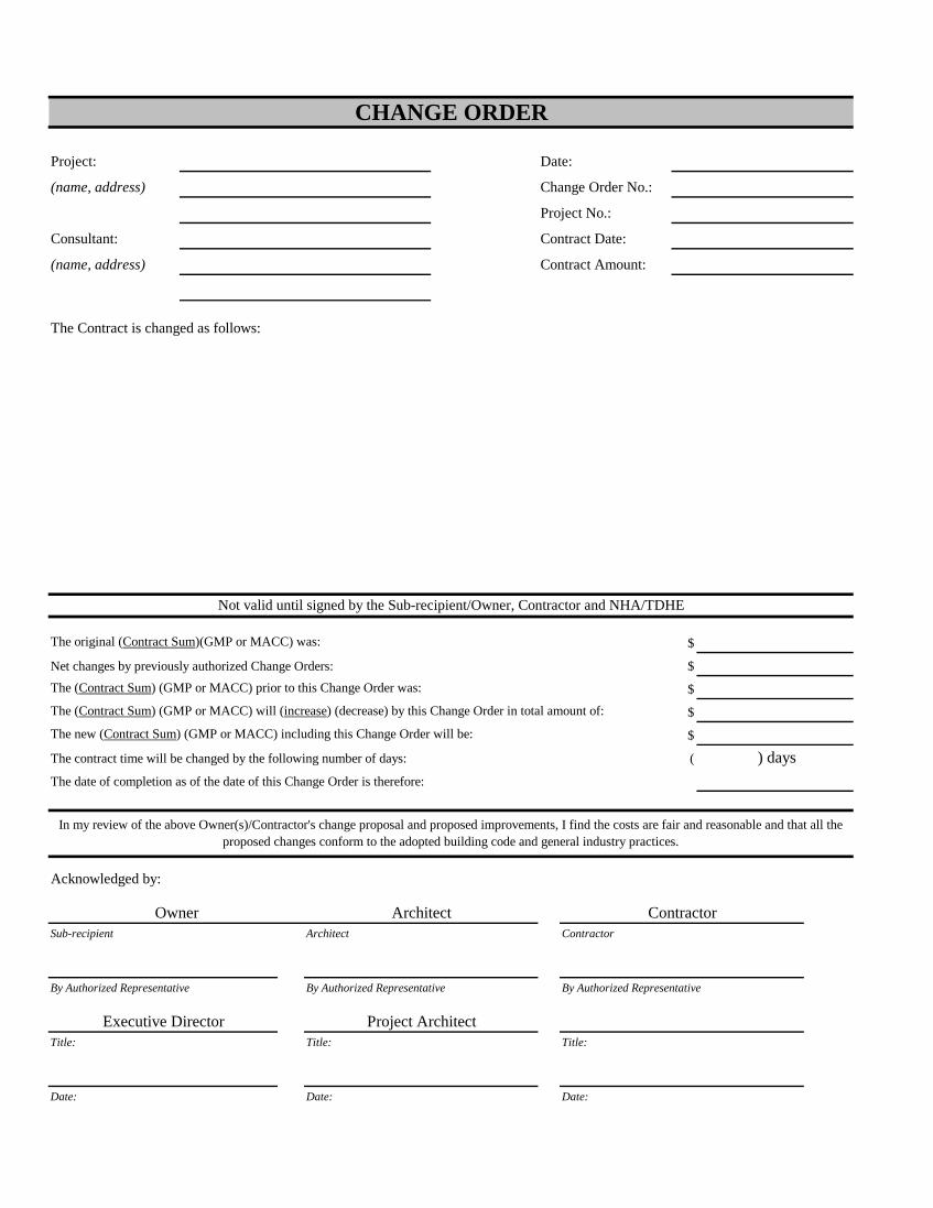
Project: Date:
(name, address) Change Order No.:
Project No.:
Consultant: Contract Date:
(name, address) Contract Amount:
The Contract is changed as follows:
The original (Contract Sum)(GMP or MACC) was: $
Net changes by previously authorized Change Orders: $The (Contract Sum) (GMP or MACC) prior to this Change Order was: $The (Contract Sum) (GMP or MACC) will (increase) (decrease) by this Change Order in total amount of: $The new (Contract Sum) (GMP or MACC) including this Change Order will be: $
The contract time will be changed by the following number of days: ( ) daysThe date of completion as of the date of this Change Order is therefore:
Acknowledged by:
Sub-recipient Architect Contractor
By Authorized Representative By Authorized Representative By Authorized Representative
Title: Title: Title:
Date: Date: Date:
CHANGE ORDER
In my review of the above Owner(s)/Contractor's change proposal and proposed improvements, I find the costs are fair and reasonable and that all the proposed changes conform to the adopted building code and general industry practices.
Not valid until signed by the Sub-recipient/Owner, Contractor and NHA/TDHE
Contractor
Executive Director
Architect
Project Architect
Owner
Division 00 SECTION 00 70 00 Conditions of the Contract
Construction Agreement Between Owner and Contractor Exhibit A Project Description Exhibit B General Conditions Exhibit C Special Conditions to General Conditions Exhibit D Plans and Specifications Exhibit F Application for Payment Exhibit G Project Schedule Exhibit H Change Order Exhibit I Change Order Exhibit J NHA Wage Rate Determination Exhibit K Supplemental Conditions for ARRA and EPA Funded Projects

Division 00 SECTION 00 71 00 Construction Agreement Between Owner and Contractor

CONSTRUCTION AGREEMENT BETWEEN
OWNER AND CONTRACTOR
Community Area Resource Enterprise, Inc (CARE 66) (“OWNER”): Company Name/Address/Phone/Fax PO Box 4298, Gallup, NM 87305
Phone: 505-722-0066 Fax: 505-722-2329
OWNER'S REPRESENTATIVE: Contact Person – Name/Address Phone/Fax/Email
Sanjay Choudhrie, PO Box 4298, Gallup, NM 87305 Phone: 505-722-0066 Fax: 505-722-2329
("CONTRACTOR"): Company Name/Address/Phone/Fax
CONTRACTOR'S REPRESENTATIVE: Contact Person – Name/Address Phone/Fax/Email
DESIGN PROFESSIONAL: Thomas Gifford, AIA Company Name/Address/ Phone/Fax Calott+Gifford
architecture │ urban Design
DESIGN PROFESSIONAL'S REPRESENTATIVE:
Contact Person – Name/Address Phone/Fax/Email
Thomas Gifford, AIA, PO Box 31934, Santa Fe, NM 87594 505-690-5898/ [email protected]
PROJECT: Name/Location Hooghan Hozho’ Multi-Family
201 Coal Ave, Gallup, NM

TABLE OF CONTENTS Page
Article 1 Definitions; The Contract Documents .............................................................................................................. 3 Article 2 The Work (Statement of Work); Subcontractors; Coordination ....................................................................... 3 Article 3 Contract Sum (Stipulated Sum) ....................................................................................................................... 4 Article 4 Enumeration of Contract Documents ................................................................................................................ 4 Article 5 Payments ........................................................................................................................................................... 5 Article 6 Commencement; Completion; Progress Schedule; Liquidated Damages ......................................................... 5 Article 7 Indian Preference .............................................................................................................................................. 6 Article 8 Bonds or Letter of Credit; Insurance ................................................................................................................ 6 Article 9 Wage Rates ....................................................................................................................................................... 6 Article 10 Governing Law; Forum and Venue; Sovereign Immunity ............................................................................... 7 Article 11 Miscellaneous ................................................................................................................................................... 7
LIST OF EXHIBITS Exhibit "A" Project Description………………………………………………………………………………………….... Exhibit "B" General Conditions………………………………………………………………………………………….... Exhibit "C" Special Conditions to the Rider to Construction Agreement And General Conditions………………………. Exhibit "D" Schedule of Values………………………………………………………………………………………….... Exhibit "E" Plans & Specifications………………………………………………………………………………………... Exhibit "F" Application for Payment…………………………………………………………………………………….... Exhibit "G" Project Schedule ……………………………………………………………………………………………... Exhibit "H" Bonds…………………………………………………………………………………………………………. Exhibit “I” Change Order…………………………………………………………………………………………………. Exhibit “J” Davis Bacon Wage Rates……………………………………………………………………………………... Exhibit “K” Supplemental Conditions for ARRA & EPA Funded Projects

TERMS AND CONDITIONS OF CONSTRUCTION AGREEMENT BETWEEN
COMMUNITY AREA RESOURCE ENTERPRISE, INC. (CARE 66) AND GENERAL CONTRACTOR This Construction Agreement (this "Agreement") is made and entered this day of 20 by and between hereinafter called "Owner" and hereinafter called "Contractor".
Owner and Contractor desire to enter into this Agreement for the construction component of the project described on Exhibit "A", attached hereto (the "Project Description"), and to set forth the terms and conditions governing the relationship between Owner and Contractor under this Agreement.
COVENANTS:
ARTICLE 1 DEFINITIONS; THE CONTRACT DOCUMENTS
1.1 Capitalized terms used in this Agreement and not otherwise defined herein, shall have the meanings designated for such terms in the General Conditions of the Agreement for Construction (the "General Conditions"), attached hereto as Exhibit "B" . 1.2 The contract documents consist of this Agreement, Conditions of the Contract (General, Supplementary and other Conditions), Plans, Specifications, addenda issued prior to execution of this Agreement, other documents listed in this Agreement and Modifications issued after execution of this Agreement (collectively, the "Contract Documents"). Contractor shall perform the Work in strict and absolute accordance with the Contract Documents. The Contract Documents form the contract between Owner and Contractor and are as fully a part of this Agreement as if set forth herein. An enumeration of the Contract Documents, other than Modifications, appears in Article 4.
ARTICLE 2 THE WORK (STATEMENT OF WORK); SUBCONTRACTORS; COORDINATION
2.1 Contractor shall perform or cause to be performed all of the Work necessary to complete the construction component of the Project in strict and absolute accordance with the Contract Documents, except to the extent specifically indicated in the Contract Documents to be the responsibility of others. Contractor shall perform all undertakings reasonably inferable from the Contract Documents as being necessary to produce the intended results for the proper and timely completion of the Work, excluding only the following which shall not be included within the Contract Sum: (Exclusions from the Scope of Work) 2.2 From time-to-time at the request of Owner (and in any event prior to the awarding of a subcontract or purchase order for a particular portion of the Work), Contractor shall furnish to Owner a written list of the names of the Subcontractors and material suppliers (including those who are to furnish materials or equipment fabricated to a special design) for whom Contractor proposes to subcontract certain of the Work, together with, such other documentation requested by Owner. Owner may, upon its review of the qualifications, capabilities and financial capacity of the Subcontractors and such suppliers, object to certain of the Subcontractors or such suppliers within ten (10) days of Owner's receipt of such list. Contractor shall not allow any Subcontractor or supplier to whom Owner has made a timely objection to perform any Work. If Owner has made a timely objection to any such Subcontractors or such suppliers, Contractor shall submit to Owner the names of substitute Subcontractors or suppliers to whom Owner has no objection. Contractor shall make no substitution for any Subcontractor or supplier engaged in the Work if Owner objects to such substitution. Contractor shall not be required to contract with anyone with whom Contractor has a reasonable objection. 2.3 Contractor shall coordinate the Work with the work performed by Owner or any separate contractor engaged by Owner under the Project.
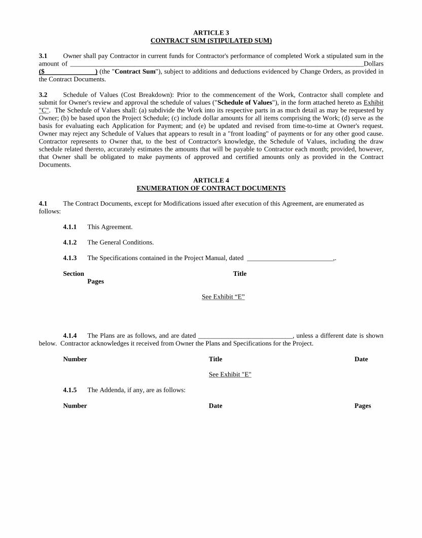
ARTICLE 3 CONTRACT SUM (STIPULATED SUM)
3.1 Owner shall pay Contractor in current funds for Contractor's performance of completed Work a stipulated sum in the amount of _______________________________________________________________________________________Dollars ($ ) (the "Contract Sum"), subject to additions and deductions evidenced by Change Orders, as provided in the Contract Documents. 3.2 Schedule of Values (Cost Breakdown): Prior to the commencement of the Work, Contractor shall complete and submit for Owner's review and approval the schedule of values ("Schedule of Values"), in the form attached hereto as Exhibit "C". The Schedule of Values shall: (a) subdivide the Work into its respective parts in as much detail as may be requested by Owner; (b) be based upon the Project Schedule; (c) include dollar amounts for all items comprising the Work; (d) serve as the basis for evaluating each Application for Payment; and (e) be updated and revised from time-to-time at Owner's request. Owner may reject any Schedule of Values that appears to result in a "front loading" of payments or for any other good cause. Contractor represents to Owner that, to the best of Contractor's knowledge, the Schedule of Values, including the draw schedule related thereto, accurately estimates the amounts that will be payable to Contractor each month; provided, however, that Owner shall be obligated to make payments of approved and certified amounts only as provided in the Contract Documents.
ARTICLE 4
ENUMERATION OF CONTRACT DOCUMENTS 4.1 The Contract Documents, except for Modifications issued after execution of this Agreement, are enumerated as follows:
4.1.1 This Agreement. 4.1.2 The General Conditions. 4.1.3 The Specifications contained in the Project Manual, dated ,. Section Title
Pages
See Exhibit “E” 4.1.4 The Plans are as follows, and are dated ____________________________, unless a different date is shown
below. Contractor acknowledges it received from Owner the Plans and Specifications for the Project. Number Title Date See Exhibit "E" 4.1.5 The Addenda, if any, are as follows: Number Date Pages

ARTICLE 5 PAYMENTS
5.1 Based upon an Application for Payment timely submitted by Contractor to Owner and Design Professional, and Certificates for Payment issued by Design Professional, Owner shall make monthly progress payments to Contractor on account of approved and certified amounts requested under an Application for Payment as provided below and in accordance with Article 11 of the General Conditions. 5.2 The pay period covered by each Application for Payment shall be one calendar month ending on the last day of the month or as follows: 5.3 On the first day of each month, Contractor shall submit to Owner and Design Professional, for their respective review, certification and approval, an Application for Payment in the form attached hereto as Exhibit "E", or such other form as Owner may require, requesting payment for Work completed during the immediately preceding month. Each Application for Payment shall be completed in accordance with the Schedule of Values, and include all supporting documentation described in Article 11 of the General Conditions. 5.4 Owner shall make monthly progress payments to Contractor on account of the Contract Sum of amounts approved under an Application for Payment, as follows:
(a) Not later than thirty (30) days following the timely submission of a complete and correct Application for Payment, Owner shall pay Contractor that portion of the Contract Sum properly allocable through the period covered by the Application for Payment, less the aggregate of (1) previous payments made by Owner; (2) the Retainage (as defined in Section 5.4(c) of this Agreement) from such previous payments and the current Application for Payment; and (3) such other amounts properly withheld pursuant to the Contract Documents;
(b) The Application for Payment may request payment for materials and equipment not yet incorporated into the Project, as provided in Article 11 of the General Conditions; and
(c) Owner may retain from each progress payment an amount equal to TEN (10%) of amounts otherwise due and payable (the "Retainage"), plus any additional amounts Owner reasonably determines are necessary to cover any of the matters described in Article 11 of the General Conditions.
5.5 Final Payment, constituting the entire unpaid balance of the Contract Sum, shall be made by Owner to Contractor within THIRTY (30) days after Contractor has accomplished Final Completion. 5.6 Owner reserves the right to issue joint checks to Contractor, and Contractor agrees to accept joint checks and, when requested by Owner, to execute joint check agreements in form acceptable to Owner. Owner shall notify Contractor prior to initiating joint check arrangements. Contractor consents to Owner communicating directly with Subcontractors to verify Contractor's payment history and account status.
ARTICLE 6 COMMENCEMENT; COMPLETION; PROGRESS SCHEDULE; LIQUIDATED DAMAGES
6.1 Contractor shall commence performance of its obligations under the Contract Documents upon the date specified in a written notice to proceed issued by Owner to Contractor. Subject to adjustments evidenced by Change Orders, Contractor shall cause the Work to be performed on an uninterrupted basis as progressively directed by Owner. 6.2 Subject to adjustments evidenced by Change Orders, Substantial Completion of the Work shall be achieved not later than CALENDAR DAYS FROM NOTICE TO PROCEED DATE (the "Substantial Completion Date"), subject only to completion of the Punch List Items included on the approved Punch List, as described in Article 11 of the General Conditions. (Insert any requirement for earlier Substantial Completion of certain portions of the Work, if not stated elsewhere in the Contract Documents) 6.3 Subject to adjustments evidenced by Change Orders, Final Completion of the Work shall be achieved not later than THIRTY (30) DAYS FOLLOWING SUBSTANTIAL COMPLETION DATE.

6.4 In addition, and subject to adjustments evidenced by Change Orders, certain elements of the Work shall be completed by the milestone dates set forth in a detailed critical path schedule for performing the Work, which schedule, when approved by Owner, shall be attached hereto as Exhibit "F" (the "Project Schedule"). The Project Schedule shall specifically identify and incorporate the number of weather-delay days anticipated by Contractor and shall otherwise conform to the requirements set forth in Article 6 of the General Conditions. 6.5 Contractor understands that if Substantial Completion is not attained by the Substantial Completion Date, subject to adjustments evidenced by Change Orders, Owner will suffer substantial damages that will be extremely difficult and impracticable to accurately ascertain. Contractor agrees that if Contractor is delayed in attaining Substantial Completion by the Substantial Completion Date, subject to adjustments evidenced by Change Orders, Contractor shall pay Owner an amount equal to FIVE HUNDRED DOLLARS ($500.00) PER DAY (the "Liquidated Damages Amount"), as liquidated damages, for each day of delay beyond the Substantial Completion Date. The Liquidated Damages Amount is a reasonable approximation of Owner's delay damages and may be assessed by Owner as and for liquidated damages, and not a penalty, in order to avoid costly litigation that would otherwise be required. Owner may deduct all liquidated damages it assesses against Contractor from any unpaid amounts then or thereafter due Contractor under this Agreement. Any liquidated damages not so deducted shall be payable by Contractor to Owner on demand. Any liquidated damages not paid within thirty (30) days of Owner's demand shall accrue interest at the prime rate of interest, as described in the Money and Investing section of the Wall Street Journal, plus four percent (4%) until paid in full. The liquidated damages provided herein shall not preclude Owner from exercising any other rights or remedies provided Owner in the Contract Documents or under Applicable Laws.
ARTICLE 7 INDIAN PREFERENCE
This Contract is subject to termination or assessments of penalties for failure to comply with the Indian Preference requirements in accordance with Article 17 of the General Conditions and as provided in other provisions of this Agreement (see Instruction to Bidders, section 7.0) and required by 24 CFR § 1000.48 -1000.54. If Contractor receives an Indian Preference, Contractor must be more than 50% Indian owned and controlled during the course of this Agreement.
ARTICLE 8 BONDS; INSURANCE
8.1 If requested by Owner, Before any Work is performed, Contractor shall furnish to, or for the benefit of, Owner and any entity providing financing or funding for the Work from time-to-time, including, but not limited to, the Navajo Nation (hereinafter, each such entity is a "Funding Source"), performance and labor and material payment bonds covering all or any portion of the Work specified by Owner. All such bonds shall (a) contain dual obligee riders naming Owner, each Funding Source, and such other parties as Owner may designate as obligees, (b) be in the form of Exhibit "H" attached hereto, and (c) otherwise fully conform with the requirements of Article 13 of the General Conditions. The premium or other costs of any such bonds shall be included in the Contract Sum. Alternatively, Owner may agree to accept other financial accommodations from Contractor, in lieu of the bonds described in this Section 8.1, including a Letter of Credit. Contractor agrees to execute reasonable forms, instruments and agreements as necessary to effectuate any such accommodations. 8.2 Prior to performing any Work, Contractor shall provide to Owner's Representative Certificates of Insurance evidencing Contractor's and any Subcontractor's compliance with the insurance requirements provided in Article 13 of the General Conditions.
ARTICLE 9 WAGE RATES
Contractor must comply with the Navajo Nation's Office of Navajo Labor Relations under the NPEA, including any licensing requirements; provided, however, Davis-Bacon Act and Davis-Bacon and Related Act Regulations. Contractor must pay applicable Davis-Bacon wage rates, which are attached as Exhibit "J. are applicable to this Contractor shall be responsible for compliance by any subcontractor or lower tier subcontractor performing construction related to the Project. in lieu of Navajo Nation wage rates for any trade classification for which the Davis-Bacon wage rate exceeds the rate of the Navajo Nation.
ARTICLE 10
GOVERNING LAW; FORUM AND VENUE; SOVEREIGN IMMUNITY 10.1 The Contract Documents shall be governed by, construed and enforced in accordance with the internal substantive
Applicable Laws of the Navajo Nation. State of New Mexico. Owner and Contractor hereby irrevocably submit to the process, jurisdiction and venue of the Navajo Nation Tribal Court ("Tribal Court"), District Courts of the State of New Mexico, which shall be the appropriate legal forum for any dispute arising under the Contract Documents. In the absence of any Applicable Laws of the Navajo Nation, the Contract Documents shall be construed first in accordance with any federal Applicable Laws, and in the absence thereof, the Applicable Laws of the State in which the Project is located; provided that reference to and use of Applicable Laws of such State does not confer any jurisdiction to such State for purposes of any dispute arising out of or relating to the Contract Documents. Without limiting the generality of the foregoing, Owner and Contractor hereby waive and agree not to assert by way of motion, defense or otherwise in any such dispute any assertion that either party is not subject to the personal jurisdiction of the Tribal Court, or that such dispute is brought in an inconvenient forum or that the venue therefor is improper. 10.2 Nothing in this agreement shall be interpreted as constituting a waiver, express or implied, of the sovereign immunity of the Navajo Nation. Furthermore, Owner hereby expressly reserves its exemption from levy or execution of judgments as set forth in 6 N.N.C § 623.
ARTICLE 11 MISCELLANEOUS
11.1 CHANGE ORDERS If, pursuant to the process set forth in Article 14 of the General Conditions, Owner determines a Change Order should be entered into, Owner and Contractor shall execute a Change Order in the form attached hereto as Exhibit "H".
11.2 PROJECT REPRESENTATIVES All decisions made by Owner's Representative and Contractor's Representative shall be binding on the respective represented party. Owner has the right, exercisable at any time, from time-to-time, to appoint a replacement Owner's Representative by providing notice thereof to Contractor. Contractor may terminate Contractor's Representative and appoint a replacement Contractor's Representative only after obtaining Owner's written approval therefor.
11.3 PERFORMANCE
Contractor represents and warrants to Owner that: (a) Contractor will perform all of its obligations under the Contract Documents in accordance with the Standard of Care; and (b) all Work performed and materials and equipment supplied under this Agreement will be: (1) in strict and absolute accordance with the Contract Documents; (2) new and free from defects; (3) of merchantable quality; and (4) fit for Owner's intended use. Work not conforming to these requirements, including substitutions not properly approved and authorized, may be considered defective by Owner. If required by Owner, Contractor shall promptly furnish satisfactory Samples of materials demonstrating that the materials comply with this Section. Neither the express warranty of this Section nor any other express warranty shall void implied warranties of habitability, merchantability, or fitness for a particular purpose.
11.4 CONTRACTOR REPRESENTATIONS AND WARRANTIES
Contractor represents and warrants to Owner as follows:
(a) Contractor's execution of this Agreement and its performance under the Contract Documents is within its duly authorized powers;
(b) Contractor is financially solvent, able to pay its debts as they mature and possessed of sufficient working capital to complete the Work and otherwise perform its obligations under the Contract Documents;
(c) Contractor is able, and has the requisite experience and competence, to complete the Work and perform all of its obligations under the Contract Documents;
(d) Contractor has carefully reviewed the Contract Documents and the information furnished by Owner, has taken field measurements, as necessary, and has verified field conditions, comparing any such field measurements and conditions and other information known to Contractor with the Contract Documents, and has reported to Owner, prior to submitting Contractor's bid proposal, any error(s), conflict(s), inconsistency(ies), or omission(s) in the Contract Documents discovered during such review and verification.

(e) Contractor is authorized to do business in the State in which the Project is located and shall at all times hold, and shall cause all persons or entities working under and through Contractor to at all times hold, appropriate registrations and licenses required by Applicable Laws, including licenses from the licensing agency of the State in which the Project is located;
(f) Contractor's employees have received or will receive all training and instruction necessary to perform the Work in conformance with the Contract Documents;
(g) The execution and delivery of the Contract Documents and performance of the Work will not result in any violation of, or default under, any term or provision of any other agreement, judgment or similar instrument to which Contractor is bound;
(h) There are no attachments, execution proceedings, assignments for the benefit of creditors, insolvency, bankruptcy reorganization or other similar proceedings pending or, to the best of Contractor's knowledge, threatened against Contractor, nor are any such proceedings contemplated by Contractor;
(i) There is no complaint, litigation, investigation or proceeding pending as of the date of Contractor's bid proposal or, to the knowledge of Contractor, contemplated or threatened against Contractor as of the date of this Agreement that would prevent Contractor from performing its obligations under the Contract Documents or any other instrument or document contemplated thereby or related thereto;
(j) Contractor is not a partner or joint venturer with Owner in connection with the Work, and Contractor is entering into this Agreement and agreeing to comply with and perform the Work in accordance with the Contract Documents voluntarily and solely for Contractor's own profit and benefit;
(k) Contractor is not, nor will Contractor engage a Subcontractor of any tier to perform Work hereunder who is, an "Excluded Party" listed on the Excluded Parties List System maintained by the U.S. General Services Administration or otherwise prohibited from being involved in a covered transaction pursuant to 24 C.F.R. Part 24; and
(l) If, at any time during the course of the Work, Contractor, or any representative of Contractor, learns of any facts or circumstances that would render any of the foregoing representations and warranties untrue, then Contractor shall promptly notify Owner of all such facts or circumstances.
11.5 INTENDED BENEFICIARY; OWNER RIGHT TO ASSUME Owner is an intended third party beneficiary of any subcontracts or purchase orders between Contractor and Subcontractors or material suppliers, without liability for benefits received, and an obligee of all express and implied warranties given by any Subcontractor or material supplier under such subcontracts or purchase orders or imposed by Applicable Laws. Owner shall be entitled to enforce such subcontracts or purchase orders directly against such Subcontractors or material suppliers in the event Owner has been damaged by any breach thereof. Any such subcontracts or purchase orders are contingently assigned to and assumable by Owner, at Owner's option.
11.6 FURTHER ACTS Each party shall execute and deliver all documents and perform all other acts reasonably necessary from time-to-time to carry out the matters contemplated herein.
11.7 ASSIGNMENT Contractor shall not assign, convey or transfer any interest in any of this Agreement without the prior written consent of Owner, which consent may be arbitrarily withheld, conditioned or delayed. In the event Owner consents to an assignment, Contractor's assignee shall assume in writing all obligations of Contractor hereunder, and Contractor shall continue to be liable for such obligations. Owner shall have the right, without limitation, to assign this Agreement, in whole or in part, to any party. This Section 11.7 notwithstanding, this Agreement shall inure to the benefit of and be binding upon Owner, Contractor and their respective successors and assigns in the event of any permitted assignment.
11.8 NOTICES AND COMMUNICATIONS
11.8.1 Any and all notices, approvals, consents or other communications required or permitted hereunder shall be given in writing and shall be delivered via: (a) facsimile (electronically confirmed by recipient); (b) personal delivery; (c) registered or certified mail, return receipt requested, postage prepaid; or (d) Federal Express, Airborne, United Parcel Service or other similar nationally recognized overnight courier; and, in each case, addressed to the applicable Project representative and, in all events, to Contractor and Owner at the addresses and/or facsimile numbers set forth on Page 1 of this Agreement. Any party may designate in writing and deliver in a like manner any changes in address at least ten (10) days before the change becomes effective.
11.8.2 Notices, approvals and other communications provided for herein shall be deemed received upon (a) electronic confirmation of receipt, if by facsimile; (b) the date of delivery to the addressee, if via personal delivery or overnight courier; or (c) three (3) days after the date of deposit in the U.S. Mail, if mailed. Notwithstanding the foregoing, any notice received after 5:00 p.m. (local time where the notice is received) shall be deemed received on the immediately following business day.
11.9 SURVIVAL All indemnities, warranties, representations and other obligations of Contractor hereunder shall survive completion of the Work and/or termination of this Agreement.
11.10 EXHIBITS AND GENERAL CONDITIONS The attached exhibits, including the General Conditions, are, by this reference, hereby incorporated herein and made a part hereof as though fully re-stated herein.
11.11 INDEPENDENT CONTRACTOR Contractor's relationship to Owner is in all respects that of an independent contractor. Contractor shall be solely responsible for the supervision, performance, coordination and control of the Work to be performed by Contractor. Contractor shall not be deemed an employee, agent or member of Owner for any purpose. Neither party shall have the right or power to bind or obligate the other party for any liabilities or obligations without the prior written consent of the other party.
11.12 COMPUTATION OF PERIODS All time periods referred to in this Agreement shall include all Saturdays, Sundays and holidays, unless the period of time specifies business days. If the date to perform any act, excluding the date on which payment is due, or give a notice with respect to this Agreement shall fall on a Saturday, Sunday or a holiday observed by the State in which the Project is located or the Navajo Nation, the act or notice may be timely performed on the next succeeding day that is not a Saturday, Sunday or a holiday observed by the State in which the Project is located or the Navajo Nation.
11.13 RELATIONSHIPS The Contract Documents shall not be construed to create a contractual relationship of any kind between any person(s) or entity(ies) other than Owner and Contractor.
11.14 TERMS USED Unless otherwise stated in the Contract Documents, words that have well-known technical or construction industry meanings are used in the Contract Documents in accordance with such recognized meanings.
11.15 CAPTIONS
Any captions to or headings of the paragraphs or subparagraphs of this Agreement are solely for the convenience of the parties, are not a part of this Agreement, and shall not be used for the interpretation or determination of the validity of this Agreement or any provision hereof.

11.16 WAIVER The waiver or failure to enforce any provision of this Agreement shall not operate as a waiver of any future breach of the provision or any other provision hereof.
11.17 COUNTERPARTS This Agreement may be executed in counterparts, each of which shall be deemed an original, but all of which together shall constitute one and the same instrument. The signature pages from one or more counterparts may be removed from the counterparts and attached to a single instrument so that the signatures of all parties may be physically attached to a single document.
11.18 CONSTRUCTION Each party has reviewed the Contract Documents to its satisfaction and agrees that any rule of construction to the effect that ambiguities are to be resolved against the drafting party shall not apply in the interpretation of this Agreement or exhibits hereto.
11.19 NO OTHER AGREEMENT This Agreement constitutes the entire agreement between Owner and Contractor with respect to the Project and shall not be modified or amended except in a written document signed by Owner and Contractor. Any prior agreements or understandings between Owner and Contractor concerning the Project are superseded and replaced by this Agreement and are hereby rendered null and void.
11.20 SEVERABILITY The provisions of this Agreement are severable and if any provision is determined to be void or unenforceable under any dispute resolution proceeding, such provision shall not affect the validity of any of the other provisions of this Agreement.
11.21 RISK OF LOSS Risk of loss shall be with Contractor until materials or equipment have been incorporated in the Site.
[REMAINDER OF PAGE INTENTIONALLY LEFT BLANK; SIGNATURES ON FOLLOWING PAGE]

IN WITNESS WHEREOF, Owner and Contractor have executed this Agreement as of the day and year set forth above.
OWNER: _____________________________, a ___________________
By:
Name:
Its: CONTRACTOR:
__________________________________, ___________ a(n) __________________________________________________
By:
Name: ___________________________________________
Its:

Division 00 Exhibit A Project Description
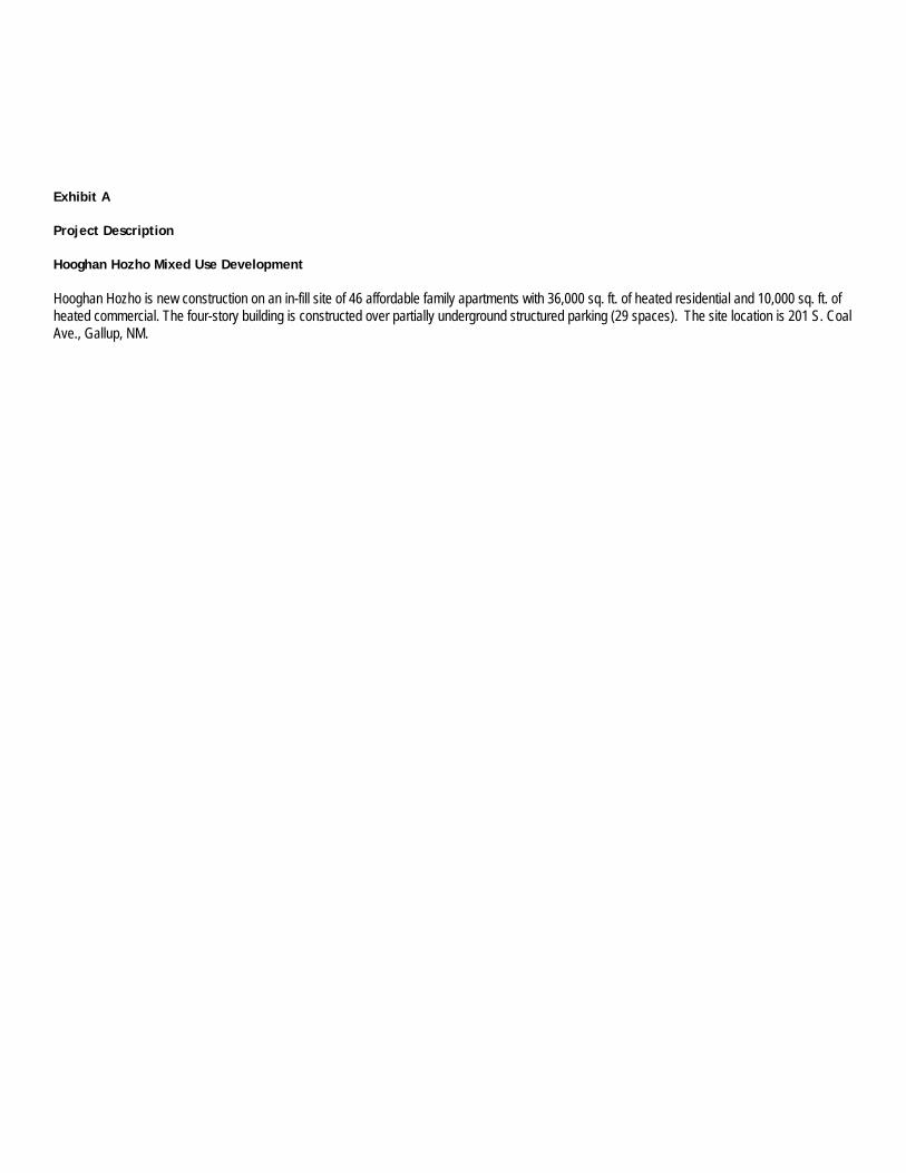
Exhibit A Project Description Hooghan Hozho Mixed Use Development Hooghan Hozho is new construction on an in-fill site of 46 affordable family apartments with 36,000 sq. ft. of heated residential and 10,000 sq. ft. of heated commercial. The four-story building is constructed over partially underground structured parking (29 spaces). The site location is 201 S. Coal Ave., Gallup, NM.

Division 00 SECTION 00 72 00 Exhibit B General Conditions of the Contract

1 General Conditions to the NHA Standard Construction Contract
GENERAL CONDITIONS of the
CONSTRUCTION AGREEMENT BETWEEN
OWNER AND CONTRACTOR
Exhibit "B"
TABLE OF CONTENTS Page Article 1 Definitions ............................................................................................................................ 2 Article 2 Correlation and Intent ........................................................................................................... 5 Article 3 Ownership and Use of Documents ....................................................................................... 6 Article 4 Design Professional; Construction Administrator ................................................................ 6 Article 5 Owner ................................................................................................................................... 7 Article 6 Contractor ............................................................................................................................. 8 Article 7 Subcontractors ...................................................................................................................... 15 Article 8 Work by Owner or by Separate Contractors ......................................................................... 16 Article 9 Tests and Costs ..................................................................................................................... 17 Article 10 Time ...................................................................................................................................... 17 Article 11 Schedule of Values, Application for Payment, Payments and Completion Schedule ........... 18 Article 12 Protection of Persons and Property ....................................................................................... 22 Article 13 Insurance and Bonds ............................................................................................................. 23 Article 14 Changes in the Work ............................................................................................................ 24 Article 15 Uncovering of Work and Correction of Work ...................................................................... 25 Article 16 Stop Order; Termination of the Contract .............................................................................. 26 Article 17 Governing Law, Federal Requirements, Indian Preference, and NEPA .............................. 28 Article 18 Undue Influence.................................................................................................................... 30

2 General Conditions to the NHA Standard Construction Contract
ARTICLE 1 DEFINITIONS
As used in these General Conditions and the other Contract Documents, the words, terms and phrases set forth below shall have the following meanings.
"Agreement" means the Construction Agreement between Owner and General Contractor to which these General Conditions are attached.
"Applicable Law(s)" means the requirements of all laws, ordinances, codes, rules, regulations, executive orders, judicial opinions, and decisions of all governmental authorities having jurisdiction over the Project, the Site, the Work, or any part thereof, including, but not limited to, the Navajo Nation, federal, state, county and local authorities. Applicable Laws include, but are not limited to, as applicable, those relating to HUD, taxes, employment (including the Navajo Nation Business Activity Tax, 24 N.N.C. § 401, et seq.),, social security, unemployment, workers' compensation, wages (including the Navajo Preference in Employment Act, 15 N.N.C. § 601, et seq.), occupational health and safety, discrimination, disability, waters of the United States, land use, waste disposal, air, water, endangered species, groundwater, environmental contamination, toxic wastes, hazardous substances, oil, petrochemicals, pesticides, herbicides, building and construction codes and standards, and contracting licensing statutes and regulations.
"Application for Payment" means the document described in Section 11.03 of the Agreement.
The term "approved" with respect to any item submitted by Contractor means that such item appears satisfactory; provided, however, that no such approval expresses or implies acceptance by Owner of the submittal as being in compliance with the Contract Documents nor is Contractor thereby relieved of its obligation therefor.
The phrase "approved as noted" means that with respect to any item submitted by Contractor, that item is approved by Owner, subject to satisfaction of any requirements noted in such approval.
"Approving Authority(ies)" has the meaning provided in Section 11.07.01 below.
"Change Order(s)" means a written instrument issued after execution of the Agreement that is signed by Owner and Contractor and authorizes (a) a change in the Work and/or (b) an adjustment in the Contract Sum and/or the Contract Time.
"Claim(s)" means any third party dispute, demand, liability, damage (whether direct or consequential), expense, penalty, fine, settlement, judgment, and any other loss.
"Confidential Information" means any and all information (and any and all documents or other media or materials containing information) that is: (a) not publicly available and that pertains to Owner or the Project, whether or not such information is expressly labeled or described as confidential; (b) expressly labeled or described as confidential; and/or (c) generated by Contractor pursuant to the Agreement, including without limitation, all reports, maps, surveys, drawings, computations, etchings, sketches, tracings, drafts and all other original documents.
"Construction Administrator" has the meaning provided in Section 4.04 below.
"Contract Documents" has the meaning provided in Article 1 of the Agreement.

3 General Conditions to the NHA Standard Construction Contract
"Contract Sum" has the meaning provided in Article 3 of the Agreement.
"Contract Time(s)" means the period of time allotted in the Contract Documents for Substantial Completion of the Work, the additional period of time allotted for Final Completion of the Work, and the time within which Contractor must complete any applicable milestone tasks as specified on the Project Schedule.
"Contractor" means the person or entity designated as such in the Agreement, or any successor of such person or entity approved by Owner in writing.
"Contractor's Representative" means the person or entity designated as such in the Agreement, or any successor of such person or entity approved by Owner in writing.
"Day" means calendar day unless otherwise specified.
"Design Professional" means Thomas Gifford, AIA, of Calott+Gifford architecture│urban design, the person or entity responsible for the design component of the Project, or applicable portion thereof.
"Final Completion" has the meaning provided in Section 11.07.03 below.
"Funding Source" has the meaning provided in Article 8 of the Agreement.
"General Conditions" means these general conditions, which are attached as Exhibit "B" to the Agreement.
"Hazardous Materials" has the meaning provided in Section 6.07.08 below.
The words "include," "includes," "including" and any other derivation of "include" means "including, but not limited to" unless specifically set forth to the contrary.
"Indemnified Parties" means Owner; the Funding Source; their affiliated entities, parents, subsidiaries, partnerships, joint ventures, limited liability companies, members, trusts, and assigns, of every tier; their respective directors, officers, partners, agents, employees, volunteers, members, managers, trustees, and shareholders; and any successors or assigns of any of the foregoing.
"Liquidated Damages Amount" has the meaning provided in Section 6.5 of the Agreement.
"Modifications" means any of (a) a written amendment to the Agreement signed by Owner and Contractor, (b) a Change Order, or (c) a written order for a minor change in the Work issued by Owner pursuant to Section 14.02 below.
"Non-conforming Work" has the meaning provided in Section 11.07.02 below.
"OSHA" has the meaning given in Section 6.07.07 below.
"Overtime" means any premium labor time within a week in excess of a work week and is subject to the provisions of Section 6.08 below.
"Owner" means the person or entity designated as such in the Agreement, or any successor of such person or entity.
4 General Conditions to the NHA Standard Construction Contract
"Owner's Representative" means the person or entity designated as such in the Agreement or any successor appointed by Owner in writing.
"Plans," "Specifications" and "Plans and Specifications" means all plans and specifications for performance of any part of the Work, including (a) the plans and specifications described in Article 3 of the Agreement; (b) Shop Drawings to be prepared by Contractor or any Subcontractor in connection with the Work and approved in writing by Owner; (c) all addenda and Modifications to any of the foregoing; and (d) any Product Data or Samples.
"Product Data" means the illustrations, standard schedules, performance charts, instructions, brochures, diagrams and other information furnished by Contractor to illustrate a material, product or system for some portion of the Work.
"Project" means the project designated as such in the Agreement's recitals.
"Project Manager" has the meaning provided in Section 6.04.01 below.
"Project Schedule" means the schedule attached as Exhibit G" to the Agreement and defined in Section 6.4 of the Agreement.
"Punch List" means the list containing the Punch List Items.
"Punch List Items" means, and shall be limited to, uncompleted and incidental items of the Work that (a) do not materially interfere with the use and occupancy of the Project for its intended purpose, and (b) as a group are capable of being completed by Contractor within thirty (30) days of issuance of any Punch List.
"Retainage" has the meaning provided in Section 5.4(c) of the Agreement.
"Samples" means physical examples that illustrate materials, equipment or workmanship and establish standards by which the Work will be judged.
"Schedule of Values" has the meaning provided in Section 11.01 below.
"Shop Drawings" means the drawings, diagrams, schedules and other data specially prepared for the Work by Contractor or any Subcontractor, manufacturer, supplier or distributor to illustrate some portion of the Work.
"Site" means the place where the Project is located.
"Standard of Care" means that degree of professional diligence and care ordinarily exercised by experienced and fully competent contractors having at least fifteen (15) years of experience constructing first-class projects that are similarly situated in scope and complexity to the construction component of the Project.
"Stop Order" has the meaning provided in Section 16.01 below.
"Subcontractor(s)" means any person or entity (other than an employee of Contractor or a Subcontractor) that contracts, directly or indirectly, with Contractor or a Subcontractor to furnish any of the Work.

5 General Conditions to the NHA Standard Construction Contract
"Substantial Completion" means the completion of all Work except Punch List Items.
"Substantial Completion Date" has the meaning provided in Section 6.2 of the Agreement.
"Superintendent" has the meaning provided in Section 6.04.02 below.
"Week" means a calendar week consisting of seven (7) days commencing at 12:01 A.M. each Monday and continuing up to and including midnight on the following Sunday.
"Work" means all labor, materials, tools, utilities, equipment, supervision, procurement, delivery, construction, installation, programming, training, start-up (including calibration, inspection and start-up operation), check-out, demonstration, testing, and other services necessary to properly construct the Project in accordance with the Contract Documents, including as set forth in, contemplated by or reasonably inferable from the Plans and Specifications, including as set forth in Article 2 of the Agreement.
"Work week" means 40 hours of labor time within a week.
ARTICLE 2 CORRELATION AND INTENT
2.01 The Contract Documents are intended to include all items necessary for the proper execution and completion of the Work; however, the enumeration of any portion of the Work shall not be construed to exclude other items contemplated by or reasonably inferable therefrom. The Contract Documents are complementary, and what is required by any one Contract Document shall be as binding as though required by all. In the event of inconsistencies within or between parts of the Contract Documents, or between the Contract Documents and Applicable Laws, Contractor shall (a) provide the better quality or greater quantity of Work; (b) comply with the more stringent requirement; and/or (c) provide the most stringent degree of obligation and liability to Owner. All of the foregoing shall be in accordance with Owner's interpretation.
2.02 The omission from the Plans and Specifications of items of construction, installation, or material that are reasonably inferable therefrom, or the failure to describe items required by sound construction practice, shall not relieve Contractor from furnishing such items in place, complete, and in a manner consistent with the Standard of Care; nor shall any such omission entitle Contractor to claim an adjustment to the Contract Sum or the Contract Time.
2.03 Figured dimensions and marked data shall take precedence over scaled measurements. In the event of any inconsistency between large scale Plans and small scale Plans, the large scale Plans shall govern. The foregoing shall not relieve Contractor of Contractor's responsibility to advise Design Professional and Owner of any inconsistency in any of the foregoing that a contractor exercising the Standard of Care should reasonably be expected to discover upon an appropriate review of the Plans and Specifications as necessary to properly perform the Work.
2.04 Specifications: Format and Interpretation
(a) Where "as shown," "as indicated," "as detailed" or other such words are used in any of the Contract Documents, reference is made to the Plans and Specifications unless otherwise stated. Where "as directed," "as required," "as permitted," "as prescribed," "reviewed," "as authorized," "as approved," "as accepted," "as selected," or words of like import are used, direction, requirement, permission, prescription, review, authorization, approval, acceptance or selection by Owner is intended unless provided otherwise.
(b) The term "provide" as used in any of the Contract Documents shall mean "provide completed in place," that is, furnished, installed, completed, tested and ready for operation or use.
(c) The terms "knowledge," "recognize," and "discover," their respective derivatives, and similar terms in the Contract Documents, as used in reference to the Contractor, shall be interpreted to mean that which the Contractor knows (or should know), recognizes (or should recognize), and discovers (or should discover) in exercising the Standard of Care required by the Contract Documents. Analogously, the expression

6 General Conditions to the NHA Standard Construction Contract
"reasonably inferable" and similar terms in the Contract Documents shall be interpreted to mean reasonably inferable by a contractor exercising the Standard of Care.
(d) Words in the singular shall include the plural whenever applicable, or if indicated by the surrounding context.
(e) As the context so requires or indicates, gender specific terms shall be inclusive of masculine, feminine and neuter usage.
2.05 If the Specifications refer to specific products of one or more manufacturers, such references are for the purpose of designating the quality of materials and equipment to be furnished and are not intended to restrict competitive bidding unless specifically noted, "No Substitute"; provided, however, that Contractor shall not use or permit the use of a product manufactured other than one of those named without prior written approval of Owner.
2.06 If typical parts or sections of the Work are completely detailed on the Plans, and other parts or sections of the Work that are essentially of the same construction are shown in outline only, the complete details shall apply to the Work that is shown in outline.
ARTICLE 3 OWNERSHIP AND USE OF DOCUMENTS
3.01 As between the parties to the Agreement, Owner shall have title to all Plans and Specifications and other Contract Documents and unlimited rights with respect to any use thereof.
3.02 As to all persons other than Owner and Design Professional, the Plans and Specifications and other Contract Documents are instruments of service of the Owner. Contractor may retain one record set of such instruments of service. Neither Contractor nor any Subcontractor of any tier shall own or claim a copyright in such instruments of service, and, unless otherwise indicated, Owner shall be deemed the author of them or the author's assignee, and will retain all common law, statutory and other reserved rights in addition to the copyright. All copies of such instruments of service, except Contractor's record set, shall be returned or suitably accounted for to Owner, upon request, upon Final Completion.
3.03 The Plans and Specifications and other Contract Documents furnished to Contractor are for use solely with respect to the Project and shall not be used by Contractor or any Subcontractor of any tier on other projects or for additions to this Project outside the scope of Work without the prior written consent of Owner. Contractor and all Subcontractors of any tier are granted a limited license to use and reproduce applicable portions of the Plans and Specifications and other Contract Documents appropriate to, and for use in, the execution of the Work. All copies made under such license shall bear the statutory copyright notice, if any, shown on the Plans and Specifications and other Contract Documents.
3.04 Contractor shall have obtained and familiarized itself with any design specifications or requirements of the Navajo Nation, federal, state and local agencies having any jurisdiction over the Work or Project before the Work commences to ensure compliance of such specifications or requirements (as applicable) with Applicable Law(s).
ARTICLE 4 DESIGN PROFESSIONAL; CONSTRUCTION ADMINISTRATOR
4.01 Owner reserves the right to delegate job administrative functions with respect to the Work to Design Professional. The Contract Documents shall not be construed to create a contractual relationship of any kind between Design Professional and Contractor.
4.02 Design Professional will provide services during the Project, including construction administration services, as provided for under that certain Design Professional Agreement dated between Design Professional and Owner. A copy of such agreement shall be provided by Owner to Contractor, and Contractor shall familiarize itself and comply with Design Professional's role described therein in the administration of the construction of the Project.
4.03 Design Professional may visit the Site at intervals appropriate to the stage of construction to become generally familiar with the progress and quality of the completed Work and to determine in general if the Work is being performed in a manner indicating that the Work, when completed, will be in accordance with the Contract Documents.

7 General Conditions to the NHA Standard Construction Contract
4.04 Owner may also, from time-to-time, engage a construction administrator ("Construction Administrator") to assist Owner in (a) administering Contractor's performance of duties under the Agreement, (b) overseeing the Project, and (c) coordinating certain of Contractor's duties under the Agreement, as specified by Owner. Owner has the right to change Construction Administrator, in Owner's sole discretion, effective upon written notice delivered to Contractor. Any Construction Administrator engaged by Owner will have the duties and authority as specified by Owner from time-to-time. Such duties may include, but are not limited to, requiring that Contractor submit to Construction Administrator Applications for Payment along with corresponding documentation, all as specified in the Contract Documents and by Owner. Contractor agrees to cooperate with any Construction Administrator appointed by Owner in accordance with written directives issued by Owner, which may be delivered to Contractor from time-to-time.
4.05 Contractor shall provide Owner, Owner's Representative, the Funding Source, Design Professional, Construction Administrator and Owner's invitees with proper and safe access to the Work at all reasonable times during the preparation and progress of the Work.
4.06 Contractor shall not directly communicate with Design Professional without obtaining Owner's prior written approval.
ARTICLE 5 OWNER
5.01 INFORMATION AND SERVICES REQUIRED OF OWNER
5.01.01 To the extent required by Contractor to perform the Work and as agreed to by Owner, Owner shall furnish surveys describing the physical characteristics, legal limitations and utility locations for the Site, as well as a legal description thereof, each to the extent available. All other grades, lines, levels, benchmarks, courses and distances shall be established and maintained by Contractor. All levels given on the Plans shall be carefully checked by Contractor with existing levels.
5.01.02 Owner shall obtain all easements required for the Work. Unless otherwise provided in the Agreement, all other permits and fees (including inspection fees) relating to the Work shall be obtained, and paid for, by Contractor as part of the Contract Sum, provided Owner and Design Professional fulfilled their respective obligations and have received approval from governmental authorities having jurisdiction over the Work or the Project.
5.01.03 Owner shall furnish to Contractor all information or services under Owner's control with reasonable promptness to avoid unreasonable delay in the orderly progress of the Work.
5.01.04 Owner will issue all instructions to Contractor through Design Professional or Owner's Representative; however, Owner reserves the right to direct and/or instruct Contractor and Design Professional simultaneously to effect changes in the Work.
5.01.05 Unless otherwise provided in the Contract Documents, Contractor will be furnished with, free of charge, one set of prints and one set of reproducible mylars of all drawings comprising the Plans and Specifications and one set of the Specifications. Additional copies of any part of such sets shall be made available to Contractor at Contractor's cost and expense.
5.01.06 Requests by Contractor for supplemental information shall be directed to Owner's Representative in writing.

8 General Conditions to the NHA Standard Construction Contract
5.02 OWNER'S RIGHT TO PERFORM CERTAIN WORK
5.02.01 If Contractor fails to carry out the Work in accordance with the Contract Documents, Owner may demand in writing that Contractor correct such failure with diligence and promptness. If Contractor does not correct such failure within seven (7) days of receiving Owner's demand, Owner may, without prejudice to any other remedy Owner may have, remedy such failure. In such event, an appropriate Change Order shall be issued deducting from the payments then or thereafter due Contractor the cost of remedying such failure, including costs related to any additional services of Design Professional made necessary by such failure. If payments then or thereafter due Contractor are not sufficient to cover such amounts, Contractor shall pay the difference to Owner on demand.
5.02.02 The rights described in this Section 5.02 and elsewhere in the Contract Documents are cumulative and not in limitation of any rights of Owner granted in the Contract Documents or under Applicable Laws or at law or in equity.
5.03 OWNER'S REPRESENTATIVE
Owner's Representative shall have full authority to receive and transmit communications on behalf of Owner. Owner's Representative shall have authority to bind Owner only as is defined in writing by Owner to Contractor.
ARTICLE 6 CONTRACTOR
6.01 STANDARD OF CARE
All Work, responsibilities and obligations performed under the Agreement by Contractor and each Subcontractor, of any tier, shall be performed in accordance with the Standard of Care. The Standard of Care shall be deemed to apply to, govern, and be the basis from which such performance shall be evaluated by Owner or any party presiding over any dispute resolution proceeding. 6.02 APPLICABLE LAWS
Contractor shall perform all Work in strict compliance with Applicable Laws.
6.03 REVIEW OF CONTRACT DOCUMENTS AND INVESTIGATION OF SITE
6.03.01 Contractor acknowledges that the Contract Documents are sufficient to enable Contractor to commence and complete the Work in accordance with Applicable Laws, and otherwise perform Contractor's obligations hereunder. Contractor shall provide Owner with prompt written notice if any of the Contract Documents, at any time, is insufficient in any way to enable Contractor to complete the Work in accordance with Applicable Laws or otherwise perform Contractor's obligations hereunder. Contractor shall report to Owner any error, inconsistency or omission Contractor may discover in the Contract Documents before Contractor performs any Work affected thereby.
6.03.02 Contractor shall not perform any portion of the Work without Contract Documents or, where required, approved (or approved as noted) Shop Drawings, Product Data or Samples.
6.03.03 Although the Plans and Specifications are understood to contain the dimensions required in the construction of the Work, Contractor shall make such changes as are necessary to make the parts of the Work fit in the best possible manner, but no alterations shall be made without Owner's prior written consent.
6.03.04 The exactness of grades, elevations, dimensions, or locations given on any Plans issued by the Design Professional, or the work installed by other contractors, is not guaranteed by the Design Professional or the Owner.
6.04 CONTRACTOR'S STAFF
6.04.01 Contractor shall appoint a project manager (the "Project Manager") for the Work who shall be authorized to act on behalf of Contractor and shall be an individual with whom Owner may consult at all reasonable times. The Project Manager shall have full supervision over the completion of the Work, shall be designated to act as the primary

9 General Conditions to the NHA Standard Construction Contract
point of contact with Owner regarding all matters relating to the Work, and shall have full authority to bind Contractor. Any changes in the Project Manager shall require Owner's prior written approval.
6.04.02 Contractor shall make available on the Site at all times during the course of the Work a qualified superintendent (the "Superintendent") who shall not be replaced without prior written notice to Owner, except under extraordinary circumstances. All communications to the Superintendent shall be as binding as if given to Contractor.
6.05 SUPERVISION AND CONSTRUCTION PROCEDURES
6.05.01 Contractor shall (a) supervise and direct the Work; (b) be solely responsible for all construction means, methods, techniques, sequences, and procedures; and (c) coordinate all portions of the Work, including coordinating its Work with the work of others on the Project.
6.05.02 Contractor accepts sole responsibility with respect to Owner for the acts and omissions of Contractor, Subcontractors and their respective agents and employees.
6.05.03 On a weekly basis, Contractor shall submit in writing to Owner a brief description of the Work, including the location thereof, an accurate manpower count broken down by trade into supervisory personnel and workers, and a listing of all major equipment on the Site.
6.05.04 Contractor shall be responsible for the conduct of all of Contractor's employees and those of the Subcontractors. Contractor shall cause all workers to eat their lunches in areas designated by Owner. Contractor shall provide, and shall ensure that all workers utilize, approved portable sanitary facilities. Contractor will not permit either its employees or those of its Subcontractors to bring or consume alcoholic beverages or narcotics on the Site. Contractor shall not permit construction workers to smoke on the Site except in areas designated therefor by Owner, if any. Contractor shall, and ensure that any Subcontractors shall, comply with any other requirements of Owner governing the Work or the Project that may be specified by Owner from time to time.
6.05.05 Contractor shall be solely responsible for the safety of the Work and all persons and property potentially impacted by the Work whether or not such safety is under the control of Contractor.
6.06 CONTRACTOR'S CONSTRUCTION SCHEDULE
6.06.01 Within five (5) days of the execution date of the Agreement, Contractor shall prepare and submit for Owner's review and approval a detailed critical path schedule for performing the Work. Such schedule, upon approval by Owner, shall be the Project Schedule from which Contractor's performance of the Work shall be measured. The Project Schedule shall be in a level of detail acceptable to Owner and shall indicate the dates for the commencement and completion of the various stages of the Work, including the dates when Owner information, approvals and Owner-furnished deliverables are required. The Project Schedule shall also include milestones for (a) a kickoff and concept review meeting, if required by Owner; (b) Site surveys and review meetings; (c) equipment and material delivery and installation; (d) downtimes for any aspect of Owner's operations; (e) training schedules; (f) start-up, check-out and performance testing; and (g) such other milestone tasks identified by Owner.
6.06.02 Owner's approval of the Project Schedule shall not relieve Contractor of its complete and exclusive control and responsibility over the construction means, methods, techniques, sequences, and procedures for executing the Work.
6.06.03 The Project Schedule shall be updated weekly by Contractor to reflect the conditions and progress of the Work, but such revisions shall not relieve Contractor of its obligations to complete the Work required under the Agreement within the Contract Time(s), as such date(s) may be adjusted in accordance with the Contract Documents. Contractor shall provide all Project Schedule updates to Owner to keep Owner advised of progress and significant changes. If Contractor fails to submit the required Project Schedule updates, Owner may withhold approval of all or part of Contractor's Applications for Payment until such time as Contractor furnishes acceptable updates.
6.06.04 If the Work falls behind the Project Schedule for any reason, Owner shall have the right to direct Contractor to take such steps as may be necessary to improve progress, including but not limited to increasing manpower, adding additional shifts of workers, and using additional days and overtime. Contractor shall be responsible for all costs associated with this recovery effort, without adjustment to the Contract Sum or Contract Time, unless the cause of the delay is

10 General Conditions to the NHA Standard Construction Contract
excusable under Section 10.02.01 hereof, in which case Contractor may seek relief for such costs in accordance with Article 14 hereof.
6.06.05 If Owner performs other work on the Project with separate contractors under Owner's control, Contractor agrees to include the activities of such contractors in the Project Schedule. Contractor shall reasonably cooperate with Owner's separate contractors and coordinate its activities with those of such separate contractors so that the Project can be completed in an orderly and coordinated manner without unreasonable disruption.
6.07 LABOR AND MATERIALS
6.07.01 Except to the extent otherwise provided in the Contract Documents, Contractor shall provide and pay for, as part of the Contract Sum, all labor, materials, equipment, tools, temporary structures, construction equipment and machinery, water, heat, lighting, utilities, transportation, sanitary facilities, and other facilities and services necessary for the proper execution and timely completion of the Work, whether temporary or permanent.
6.07.02 Contractor shall (a) at all times enforce strict discipline and good order among Contractor's employees and shall not employ in the performance of the Work any unfit or unskilled person; (b) store Contractor's materials, equipment, tools, supplies and the operations of its workmen and Subcontractors within areas designated by Owner from time-to-time; (c) not unnecessarily burden the Work area; and (d) correct, at Contractor's expense, damage to property resulting from the Work.
6.07.03 Contractor shall (a) protect the Work from weather, theft and vandalism and (b) properly store and protect materials, equipment, tools and supplies delivered to the Site.
6.07.04 Manufacturers' printed instructions covering details of installation shall be followed if not in conflict with the Specifications. If there is a conflict between such instructions and the Specifications, Contractor shall notify the Owner at once and obtain the Owner's approval or instructions before proceeding.
6.07.05 Completed Work shall be left plumb, level, true to line or plane, anchored securely in place, and free from damage. All Work shall be constructed according to the Standard of Care.
6.07.06 With respect to all excess materials, Contractor shall first attempt to return all such materials for credit to Owner's account to the extent such returns are available, and then, recycle such materials (with any credits or payments received therefor being for Owner's account), before disposing of such materials in accordance with Section 6.07.09.
6.07.07 Contractor shall comply with, and cooperate with Owner and other contractors and Subcontractors in connection with their compliance with, the regulations of the Occupational Safety and Health Act of 1970, as amended ("OSHA"), or any similar applicable state law.
6.07.08 Contractor shall not use, in connection with the Work, any hazardous waste, toxic substance or related materials ("Hazardous Materials") in such manner as would (a) violate any Applicable Laws; (b) cause any damage or a risk of any damage to the environment; or (c) leave any residue that could be hazardous to persons or property or cause liability to Owner. The term "Hazardous Materials" shall include substances defined as "hazardous substances" or "toxic substances" in the Comprehensive Environmental Response, Compensation and Liability Act of 1980, as amended, 42 U.S.C. Sec. 9061, et seq.; Hazardous Materials Transportation Act, 49 U.S.C. Sec. 1802; the Resource Conservation and Recovery Act, 42 U.S.C. Sec. 6901, et seq.; asbestos containing material; and PCBs. The foregoing shall not be deemed to prohibit Contractor from using in the Work any item specified by name in the Plans and Specifications. Contractor shall provide Owner with prompt written notice of the existence of any Hazardous Materials located on the Site upon Contractor's becoming aware of the existence of such Hazardous Materials and, in any event, prior to disturbing such Hazardous Materials.
6.07.09 Contractor shall cause all waste produced at the Site to be properly disposed of off the Site in accordance with all Applicable Laws. Contractor shall not permit any such waste to enter or be disposed in any drainage or sewer system connecting with or constituting a portion of the Project.
6.08 OVERTIME

11 General Conditions to the NHA Standard Construction Contract
6.08.01 The Contract Sum is based on the Project Schedule. Except as expressly provided for in the Contract Documents, Contractor shall not be entitled to any increase in the Contract Sum for overtime required to complete the Work in accordance with the Project Schedule.
6.08.02 If Owner requests that Contractor work overtime, Contractor shall comply with the following requirements:
(a) Contractor shall prepare and submit in triplicate to Owner on a daily basis, a statement of employees by name, trade, classification, hourly rate, and premium or overtime charges worked to substantiate premium or overtime charges, in such detail to demonstrate to Owner the accuracy of the statement, and
(b) Owner will pay for authorized overtime work only in amounts actually paid for by Contractor for actual overtime premium wages, actual contributions paid to federal and state unemployment tax and federal insurance contributions tax. No overhead or profit shall be included in actual overtime premium wages except in those instances in which Owner requests an acceleration of the Project Schedule in writing.
6.09 TAXES
Included within the Contract Sum are all sales, transaction privilege, consumer, use, personal property and other similar taxes applicable to the Work or any portion thereof,. including taxes payable under the Navajo Nation Business Activity Tax (24 N.N.C. Sec. 401 et seq.)
6.10 PERMITS, FEES AND NOTICES
6.10.01 Except as specifically identified in the Contract Documents as being the responsibility of Owner, Contractor shall obtain and pay for, as part of the Contract Sum, all necessary permits, approvals, licenses, government charges and inspection fees required for the prosecution of the Work by any government or quasi-government entity having jurisdiction over the Project. Contractor shall provide reasonable assistance to Owner in obtaining those permits, approvals and licenses that are Owner's responsibility under the Contract Documents.
6.10.02 Prior to the execution of any Work, Contractor shall provide evidence of current licensure of Contractor and Subcontractors, as applicable, conforming to all codes and requirements of the contractor licensing statutes and regulations of the jurisdiction in which the Project is located.
6.10.03 Contractor shall give all notices and comply with all Applicable Laws bearing on the performance of the Work, and, with the requirements and standards established by technical societies, institutions or associations that have established requirements and standards relating to portions of the Work.
6.11 DOCUMENTS AND SAMPLES AT THE SITE
6.11.01 Contractor shall maintain at the Site for Owner one record copy of all current and up-to-date Plans, Specifications, addenda, Change Orders and other Modifications, in good order and marked to reflect all changes made during construction, and approved Shop Drawings, Product Data and Samples. Contractor shall submit to Owner two (2) complete sets (one to be reproducible in a format approved by Owner) and an electronic file in AutoCAD format or such other software as approved by Owner, including descriptions, drawings, sketches, marked prints, and similar data indicating the Work in its "as-built" condition. Contractor shall keep "as-built" record drawings up to date concurrently as the Work progresses. Contractor shall submit such drawings to Owner with its final Application for Payment, which submittal shall be a condition precedent to Owner's obligation to make final payment.
6.11.02 No review or receipt of any of the information described in Section 6.11.01 by Owner shall be deemed a waiver or approval of any deviation of any of the same from the Contract Documents, including the Shop Drawings, or in any way relieve Contractor from Contractor's responsibility to perform the Work in accordance with the Contract Documents.
6.11.03 Contractor shall furnish to Owner four (4) complete sets of manuals containing the manufacturers' instructions for maintenance and operation of each item of equipment furnished under the Contract Documents and any additional data specifically requested under the various sections of the Specifications. The manuals shall be arranged in proper order, indexed and suitably bound.

12 General Conditions to the NHA Standard Construction Contract
6.12 SHOP DRAWINGS, PRODUCT DATA, AND SAMPLES
6.12.01 The purpose of the Shop Drawings, Product Data, Samples and similar submittals is to demonstrate Contractor's conformance to the information provided and the design concept expressed in the Contract Documents.
6.12.02 Contractor shall procure, review, and submit, with reasonable promptness and in such sequence as to cause no delay in the Work or in the work of Owner or any separate contractor, all Shop Drawings, Product Data and Samples required by the Contract Documents. Contractor shall promptly prepare and deliver to Owner a complete and detailed schedule specifying all submittals that are required or anticipated to be delivered by Contractor hereunder, which schedule shall permit Owner and Owner's other consultants ten (10) business days to review any such submittals.
6.12.03 Owner's approval of Shop Drawings, Product Data or Samples, pursuant to the Contract Documents or otherwise, shall not relieve Contractor from responsibility for (a) errors or omissions therein or (b) any deviation from the requirements of the Contract Documents unless Contractor has specifically informed Owner of such deviation in writing and Owner agrees, in writing, to such deviation.
6.12.04 Contractor shall direct specific attention, in writing or on resubmitted Shop Drawings, Product Data or Samples, to revisions other than those requested by Owner on previous submittals.
6.12.05 Contractor shall perform no portion of the Work requiring submission of a Shop Drawing, Product Data, Samples or similar submittals if the respective submittal has been rejected by Owner. Performance of such portion of the Work, to the extent the same shall not be in accordance with subsequently approved submittals, shall be at Contractor's sole risk, shall be deemed defective Work, and shall be corrected by Contractor pursuant to Section 15.02 below.
6.12.06 Contractor warrants that all Plans and Specifications prepared by or for Contractor for any part of the Work shall fully comply with all Applicable Laws; provided, however, that Contractor shall not be responsible for defects or deficiencies in any of the foregoing to the extent such are attributable to the Design Professional or any person or entity other than Contractor or a Subcontractor if such defects or deficiencies should not have been discovered by a contractor exercising the Standard of Care. If Contractor observes or becomes aware that any of the Plans and Specifications or any other part of the Contract Documents do not comply with Applicable Laws in any respect, Contractor shall promptly notify Owner in writing, and any necessary changes shall be accomplished by appropriate Modification. If Contractor performs any Work knowing, or if Contractor reasonably should have known, it to be contrary to any Applicable Laws, Contractor shall make all changes necessary to comply therewith and shall assume full responsibility and bear all costs attributable to the correction of such Work.
6.12.07 All Shop Drawings, Product Data, Samples and similar submittals with respect to the Work shall become the property of Owner upon Final Completion.
6.13 USE OF SITE
6.13.01 Contractor shall confine the Work to the limits indicated by Applicable Laws, or as may be established by Owner from time to time.
6.13.02 Only materials and equipment that are used directly in the Work shall be brought to and stored on the Site by Contractor. Materials or equipment no longer required for the Work shall be promptly removed from the Site.
6.13.03 All construction related traffic, including truck traffic and deliveries with respect to the Work, shall enter and leave the Site only at Owner approved locations. Contractor shall stage the Work, from time to time, only at such portions of the Site as approved by Owner. Contractor shall, with no increase in the Contract Sum, move Contractor's staging area as and when requested by Owner.
6.14 CUTTING AND PATCHING OF WORK
6.14.01 Contractor shall be responsible for all cutting, fitting, patching, excavating or other alterations required to allow the Work to properly fit together. All cutting, fitting, patching, excavating or other alterations shall be done promptly and all other repairs shall be made as necessary to leave the entire Work in good condition.
13 General Conditions to the NHA Standard Construction Contract
6.14.02 Contractor shall not damage or endanger any portion of the Work or the work of Owner or any separate contractor by cutting, fitting, patching, excavating or otherwise altering the Work or such other work. Contractor shall not otherwise alter the work of Owner or any separate contractor except with the written consent of Owner.
6.14.03 If sleeves or hangers are not placed in time, or are improperly placed, Contractor shall be responsible for forming or drilling openings in the Work as required and for any patching or corrective work necessary, subject to the approval thereof by Owner and at no additional charge to Owner.
6.14.04 The cutting and chasing of existing construction for installation of mechanical and electrical Work and for the relocation of existing pipes, ducts, conduit and the like shall be the performed by trades licensed to perform such Work.
6.14.05 Structural members shall not be cut or drilled and floors, walks, footings and partitions shall not be cut except with the prior written approval of Owner. Performance of such Work without such approval shall be at Contractor's sole risk and expense.
6.14.06 Penetration of the slab of any floor shall be core drilled in accordance with procedures to be approved by Owner before such Work is performed.
6.15 CLEANING UP
6.15.01 Contractor shall, at all times, keep the Site and, to the extent Contractor is granted access, areas adjacent to the Site and any surrounding areas in a neat and orderly condition and free from accumulation of waste materials or rubbish caused by Contractor's operations. Contractor shall clear all dirt, mud and debris from the streets surrounding the Site and, to the extent Contractor is granted access, areas adjacent to the Site and any surrounding areas so that such streets are broom clean at the end of each day. Contractor shall not, and shall not allow its Subcontractors to, burn any trash at the Site and any surrounding areas or elsewhere in the vicinity of the Site.
6.15.02 Contractor shall, and shall require its Subcontractors to, clean and maintain their respective portions of the Work as required on a daily basis and as directed by Owner. As to unsalvageable materials disposed of off the Site, Contractor shall ensure such materials are disposed of at an approved landfill in full conformity with Applicable Laws.
6.15.03 If the Site or, to the extent Contractor is granted access, areas adjacent to the Site and any surrounding areas are not properly maintained, Owner may, upon twenty-four (24) hours notice to Contractor (or such shorter period as may be specified in any notice from a governmental authority with respect thereto), perform such maintenance and charge the cost therefor to Contractor.
6.15.04 In order to make the Work fit for occupancy and for its intended purposes upon Substantial Completion, Contractor shall remove all temporary facilities, waste materials and rubbish from and about the Site and, to the extent Contractor is granted access, the areas adjacent to the Site and any surrounding areas, as well as, all supplies, tools, construction equipment, machinery and surplus materials. In addition, at Substantial Completion, Contractor shall perform the following final cleaning:
(a) Remove temporary protections;
(b) Remove grease, mastic adhesives, dust, dirt, stains, fingerprints, labels and other foreign materials from sight-exposed interior and exterior surfaces;
(c) Wash and shine glazing and mirrors;
(d) Polish glossy surfaces to a clear shine;
(e) Ventilating Systems: clean permanent filters and replace disposable filters if units were operated during construction; and clean ducts, blowers and coils if units were operated without filters during construction;
(f) Broom clean exterior paved surfaces; rake clean the grounds on the Site;
(g) Sweep up and thoroughly clean all carpeting; and

14 General Conditions to the NHA Standard Construction Contract
(h) Snake all primary sanitary sewer lines that tie into the public sewer system and clean all storm drains.
6.15.05 Contractor shall use only cleaning materials that are in compliance with Applicable Laws and in a manner that will not damage any of the Work or the Site. Any glass or other Work damaged by Contractor or any Subcontractor shall be replaced and all surfaces that have been scratched or marred shall be refinished at no additional cost to Owner. All cleaning materials and methods shall comply with the recommendations of the manufacturer of the surface being cleaned.
6.16 ROYALTIES AND PATENTS
Contractor shall pay all royalties and license fees applicable to the Work and shall not unlawfully use or install any patented component of the Work. If any injunction or legal action seeking to stop the Work occurs, Owner may require Contractor to substitute such other articles of like kind as will make it possible to proceed with and complete the Work, and all costs and expenses occasioned thereby shall be borne by Contractor to the extent resulting from Contractor's failure to comply with the preceding sentence. The review by Owner of any non-specified method of construction, invention, appliance, process, article, device or material of any kind shall be for its adequacy related to the Work only, and shall not be an approval of Contractor's use thereof in violation of any patent or other rights of any third party. 6.17 INDEMNIFICATION
6.17.01 To the fullest extent permitted by Applicable Laws, Contractor agrees to defend, indemnify and hold harmless the Indemnified Parties for, from and against any and all Claims arising out of or related to performance of the Work, whether sustained or asserted before or after the date of Final Completion or termination of the Agreement, and all attorneys' fees, consultants' fees, and all other expenses, whether or not taxable, incurred by any of the Indemnified Parties in the investigation, defense, settlement and satisfaction thereof. This indemnity extends to and includes all Claims, just or unjust, whether based on a tort, strict liability, contract, lien, stop notice, Applicable Laws or other theory of relief or liability, and whether the injury complained of arises from any death, personal injury, sickness, disease, property damage (including loss of use), trespass, economic loss, patent infringement, copyright infringement, hazardous substance release, oil discharge, waste disposal, taking of endangered species, or otherwise; provided, however, that if a Claim against any of the Indemnified Parties is based on a negligence theory of recovery, this Agreement to defend, indemnify, and hold harmless shall extend only to the extent the Claim is caused or alleged to be caused by the negligent acts, errors or omissions of Contractor or any person or entity for whom Contractor may be responsible. Contractor's indemnification obligation shall be without regard to any restriction on the compensation or benefits payable by or for Contractor or any subcontractor under any Applicable Laws governing workers' compensation.
6.17.02 Contractor expressly understands and agrees that any performance or labor and material bond or insurance protection required by any provision of the Contract Documents, or otherwise provided by Contractor, shall in no way limit the responsibility to defend, indemnify and hold harmless each of the Indemnified Parties as herein provided.
6.17.03 Contractor shall cause the provisions of this Section 6.17 to be included in each subcontract between Contractor and a Subcontractor and flow down to such other subcontracts entered into between a Subcontractor and its Subcontractors. At Owner's request, Contractor shall provide evidence satisfactory to Owner that it has fulfilled its obligation under this Section 6.17.
6.17.04 If any Claim indemnified hereunder but not accepted for coverage by Contractor's insurance policies has not been settled or discharged when the Work is completed, final payment of the Contract Sum shall not be due unless and until Contractor provides (a) a bond issued by a bonding company satisfactory to Owner, or (b) other security acceptable in an amount equal to 150% of the amount of any such Claim, including interest on such Claim as estimated by Owner. Such bond or other security shall be in form and substance satisfactory to Owner and shall be subject to such increase as Owner may from time to time require as interest accrues on such Claim.
6.17.05 All indemnities, warranties, representations and other obligations of Design Professional shall survive Final Completion and/or termination of the Agreement.
6.18 TEMPORARY OFFICE
At all times prior to Final Completion, Contractor shall provide and maintain a weather-tight, temporary office at the Site for Contractor's use at a location satisfactory to Owner. Such temporary office shall be fully functional and complete with

15 General Conditions to the NHA Standard Construction Contract
utility hookups for power, heat, air-conditioning, and light and telephone service. The costs and expenses related to the provision and maintenance of such temporary office shall be included within the Contract Sum.
6.19 UTILITY COSTS; WORK AROUND UTILITIES
6.19.01 Except as otherwise provided for in the Agreement, Contractor shall provide and pay for all heating, cooling, lighting, utilities, and other facilities and services necessary for the proper execution and completion of the Work. Contractor shall furnish and maintain all temporary ventilating equipment as required prior to the installation of the permanent heating and cooling apparatus. As soon as the permanent heating and cooling apparatus has been fully installed, Contractor shall have the right to use the same in accordance with and subject to the provisions of Section 11.3 of the Agreement. Except as otherwise provided in the Agreement, all utility costs with respect to each portion of the Work shall be provided, and paid for, by Contractor, as part of the Contract Sum, until the date of Substantial Completion.
6.19.02 Contractor shall be responsible to cause all existing utilities to be located. Contractor shall hand excavate in proximity to located utilities. Contractor shall be responsible, without an increase in the Contract Sum, for all costs resulting from located utilities damaged during the Work.
6.20 CONFIDENTIAL RELATIONSHIP; NEWS RELEASES
In connection with the rendering of the Work, Confidential Information may be discovered by or disclosed to Contractor. Contractor agrees to treat all Confidential Information with the highest duty of trust imposed upon a fiduciary, not to disclose or allow access to any Confidential Information to any person (including employees of Contractor, except as necessary to perform the Work), to refrain from using Confidential Information for purposes other than the performance of the Work or as otherwise directed by Owner, to refrain from reproducing any Confidential Information except as necessary to perform the Work, and to return to Owner all documents and other materials containing Confidential Information immediately upon Owner's request and in any event upon the termination of the Agreement or completion of the Work. Contractor acknowledges that Owner will not have an adequate remedy under any Applicable Laws for any breach of the foregoing provisions, and that, accordingly, Owner may obtain injunctive relief or a decree of specific performance directing Contractor to cure any such breach and to refrain from further actions that would constitute such a breach. Contractor acknowledges and agrees that its obligations hereunder and all other confidentiality provisions of the Contract Documents are as a fiduciary to Owner and that any release of Confidential Information by Contractor contrary to these confidentiality provisions shall be subject to all remedies and damages available to Owner at law or equity for breach of fiduciary duty.
6.21 NO STOPPAGE
Contractor shall not directly or indirectly stop performance of any Work in the event of a Claim or other dispute. Rather, Contractor will continue performance, under protest, pending resolution of such Claim or other dispute unless Owner specifically directs otherwise in writing. Contractor's failure to continue such performance shall be a material breach of the Agreement.
ARTICLE 7 SUBCONTRACTORS
7.01 SUBCONTRACTUAL RELATIONS
7.01.01 Each subcontract and purchase order entered between Contractor and a Subcontractor or material supplier shall:
(a) be in writing;
(b) specifically incorporate the Agreement by reference in its entirety;
(c) be accompanied by such proof of insurance as Owner shall require;
(d) provide that Owner is an intended third party beneficiary of the subcontract or purchase order (without liability for benefits received) and an obligee of all express and implied warranties given by any Subcontractor or material supplier under such subcontracts or purchase orders or as imposed by Applicable

16 General Conditions to the NHA Standard Construction Contract
Laws, with the right to directly enforce those obligations as a principal, whether before or after Final Completion;
(e) provide the Subcontractor or material supplier's consent to be joined in any dispute resolution procedure or proceeding involving Owner and Contractor;
(f) provide that Owner shall be entitled to enforce such subcontract or purchase order directly against such Subcontractor or material supplier in the event Owner has been damaged by any breach thereof;
(g) provide the Subcontractor or material supplier's consent that any such agreement or purchase order may be assigned to Owner at Owner's option if the Agreement is terminated for any reason and obligate the Subcontractor or material supplier to perform for the benefit of Owner the remainder of the Work covered by such agreement or purchase order as long as Owner continues to pay the amounts owing such Subcontractor or material supplier thereunder;
(h) require, to the extent of the Work to be performed by the Subcontractor or materials to be supplied by the material supplier, each Subcontractor or material supplier be bound to the Contractor by the terms of the Contract Documents and to assume toward Contractor all the obligations and responsibilities that Contractor assumes toward Owner under the Agreement, including the responsibility for the safety of the Subcontractor's Work; and
(i) require each Subcontractor or material supplier to enter into similar agreements with its Subcontractors.
7.01.02 Contractor shall coordinate the efforts of its Subcontractors and material suppliers so that no part of the Work is duplicated or omitted, and shall require its Subcontractors and material suppliers to proceed with the Work in accordance with the Project Schedule and in such order as Contractor may direct. Contractor agrees that it is as fully responsible to Owner for the acts and omissions of its Subcontractors, material suppliers and of persons either directly or indirectly employed by them as Contractor is for the acts and omissions of persons directly employed by Contractor.
7.01.03 The preceding Section 7.01.01 notwithstanding, nothing contained in the Contract Documents shall create any contractual obligation between any Subcontractor or material supplier and Owner.
7.01.04 Contractor shall require each Subcontractor and material supplier to carry insurance having limits, coverages and deductibles required by Owner, in Owner's sole and absolute discretion.
ARTICLE 8 WORK BY OWNER OR BY SEPARATE CONTRACTORS
8.01 OWNER'S RIGHT TO PERFORM WORK AND TO ENTER SEPARATE CONTRACTS
Owner reserves the right to perform certain of its own work and enter into contracts with separate contractors and subcontractors in connection with the Project. Contractor shall provide Owner and such other contractors and subcontractors reasonable opportunity to introduce and store their materials and execute their work, and shall properly connect and coordinate Contractor's Work with the work of Owner and such other contractors and subcontractors. 8.02 MUTUAL RESPONSIBILITY
8.02.01 If any part of the Work depends for proper execution or results upon the work of Owner or any separate contractor or subcontractor, Contractor shall, prior to proceeding with the Work, promptly notify Owner of any apparent discrepancies or defects in such other work that render it unsuitable for Contractor's Work. Failure of Contractor to provide such notice shall constitute an acceptance of such other work as suitable to receive Contractor's Work.
8.02.02 Should Contractor cause damage to the Work or property of Owner or any separate contractor or subcontractor, or to other work in the vicinity of the Project, including damage caused by defective work, Contractor shall promptly remedy such damage and attempt to resolve any dispute arising therefrom.

17 General Conditions to the NHA Standard Construction Contract
ARTICLE 9 TESTS AND COSTS
9.01 TESTS
9.01.01 If the Contract Documents or any Applicable Laws require any portion of the Work to be inspected, tested or approved, Contractor shall provide Owner timely notice (not less than 48 hours' prior notice) of its readiness therefor so Owner may observe such inspection, testing or approval. Contractor will arrange for the services of a testing laboratory(ies) or service organization designated by Owner for purposes of such inspections, tests or approvals.
9.01.02 If any inspection, testing or approval reveals a failure of the Work to comply with the requirements of the Contract Documents, Contractor shall bear the costs and expenses to correct such failure, including payment of any additional compensation to Design Professional made necessary by such failure.
9.01.03 Required certificates of inspection, testing or approval shall be secured by Contractor and promptly delivered to Owner.
9.01.04 Contractor shall coordinate the activities of all entities conducting inspections, tests or approvals by or for Owner and shall cooperate fully with such entities so as to facilitate such inspections, tests or approvals.
9.01.05 Separate testing required or performed by Owner that is consistent with normal practice in constructing projects similar to the Project shall not entitle Contractor to any adjustment in the Contract Sum or the Contract Time.
9.02 COSTS
All cash discounts received by Contractor related to the Work shall accrue to Owner in total, and all quantity and trade discounts, rebates, refunds and all returns from sale of surplus material shall be applied as a reduction of the Contract Sum. Contractor shall notify Owner of, and qualify for available cash discounts, quantity and trade discounts, rebates, refunds and all returns from sale of surplus materials in any way related to the Work to the extent available in a manner consistent with the Contract Documents. At Owner's request, Contractor shall assist in the sale of surplus materials.
ARTICLE 10 TIME
10.01 PROGRESS AND COMPLETION
10.01.01 All time limits stated in the Contract Documents for the performance of Contractor's obligations are of the essence.
10.01.02 Contractor shall commence and carry the Work forward expeditiously with adequate forces and shall achieve Substantial Completion and Final Completion within the time periods provided therefor in Article 6 of the Agreement.
10.01.03 If Owner desires to accelerate performance of any part of the Work, Owner may request such acceleration, in which event Contractor shall advise Owner to what extent if any, in the judgment of Contractor, overtime Work will be required to accomplish such acceleration and the estimated extra actual out-of-pocket cost resulting from the use of such overtime. Upon receipt of such estimate from Contractor, if Owner still desires to accelerate performance of such part of the Work, Owner shall issue a Change Order for the Work Contractor shall perform on an accelerated basis.
10.02 DELAYS AND EXTENSIONS OF TIME
10.02.01 After all float time is used, the Contract Time may be extended by Change Order for such reasonable time as Owner may determine if Contractor is delayed in completing the Work because of: (a) any act or neglect of Owner or the Design Professional or by any employee of either, or by a separate contractor or subcontractor, but not including Subcontractors engaged by Contractor; (b) changes in the Work if the Work affected by the changes is on the critical path of the Project Schedule; (c) labor disputes, fire, unusual weather or floods; (d) any other cause beyond Contractor's reasonable

18 General Conditions to the NHA Standard Construction Contract
control and without Contractor's negligence; (e) delay authorized by Owner; or (f) any cause that Owner determines may justify the delay.
10.02.02 A request for an extension of the Contract Time shall be made in writing to Owner, not more than seven (7) days after commencement of the occurrence giving rise to such request, otherwise such request will be waived. In the case of a continuing cause of delay, only one such request is necessary. Such request must be accompanied by complete documentation showing the current status of Work affected and the nature and exact duration of the requested extension. A request by the Contractor for an extension of the Contract Time under this Section 10.02.02 shall be a prerequisite to Contractor later claiming additional compensation as a result of Owner's acceleration or delays. Provided Owner has received a timely and proper request, within thirty (30) days after receiving such request, Owner shall determine, in Owner's reasonable discretion, whether a Change Order should be entered into on account of any of the causes described in Section 10.02.01.
10.02.03 Contractor recognizes that completing the Work on or before the original Contract Time(s) is of the utmost importance. Consequently, notwithstanding the right of Contractor to receive a time extension pursuant to Section 10.02.01, Contractor agrees that if it encounters a delay, it will, if directed by Owner under Section 6.06.04, develop and implement a schedule and plan to improve progress and overcome such delay.
10.02.04 In the event of any dispute whatsoever between Owner and Contractor, Contractor shall continue to proceed diligently with the Work as required by the Contract Documents, provided Owner continues to make undisputed payments on account of the Contract Sum as provided for in the Agreement.
ARTICLE 11 SCHEDULE OF VALUES, APPLICATION FOR PAYMENT, PAYMENTS AND COMPLETION SCHEDULE
11.01 SCHEDULE OF VALUES
Contractor shall complete and submit for Owner's review and approval the schedule of values ("Schedule of Values") for all of the Work in the form attached as Exhibit "C" to the Agreement. The Schedule of Values shall: (a) subdivide the Work into its respective parts; (b) be based upon the Project Schedule; (c) include dollar amounts for all items comprising the Work; (d) serve as the basis for evaluating Contractor's Applications for Payment; and (e) be updated and revised from time-to-time at Owner's request. Owner may reject any Schedule of Values that appears susceptible to resulting in a "front loading" of payments or for any other good cause. Contractor represents to Owner that, to the best of Contractor's knowledge, the Schedule of Values, including the draw schedule related thereto, accurately estimates the amounts that will be payable to Contractor each month; provided, however, that Owner shall be obligated to make payments in approved amounts only as provided in the Contract Documents.
11.02 APPLICATION FOR PAYMENTS SUBMITTED TO OWNER'S REPRESENTATIVE
All written communications from Contractor regarding payment shall be personally delivered to Owner's Representative who is designated as Owner's exclusive agent for purposes of such communications. No such communication shall be deemed received by Owner's Representative until it has been actually received by Owner's Representative. 11.03 APPLICATION FOR PAYMENT
11.03.01 The Application for Payment may request payment for equipment and materials not yet incorporated into the Project, provided that: (a) Owner has agreed in writing that the equipment and materials are suitably stored at another acceptable location; (b) the equipment and materials are protected by suitable insurance; (c) the equipment and materials are properly identified as being for Owner's Project; and (d) upon payment, title to such equipment and materials will pass to Owner free and clear of all claims, liens, encumbrances, and security interests. Payment for equipment and materials made in accordance with this Section 11.03.01 shall be subject to a retainage of ten percent (10%) or as otherwise provided in the Agreement.
11.03.02 The Application for Payment shall constitute Contractor's representation that the Work has been performed consistent with the Contract Documents, has progressed to the point indicated in the Application for Payment, and that title to all Work will pass to Owner free and clear of all claims, liens, encumbrances, and security interests upon the incorporation of the Work into the Project, or upon Contractor's receipt of payment, whichever occurs earlier. Values shall be assigned to individual items of Work in a manner that will avoid any "front loading" of payments.

19 General Conditions to the NHA Standard Construction Contract
11.03.03 Owner shall have the right to withhold the Retainage as provided in Section 5.4(c) of the Agreement. All requests for a reduction in Retainage shall be submitted in writing for Owner's approval and shall include consent of Contractor's surety, if any.
11.03.04 Other than the equipment and materials referenced in Section 11.03.01, no Application for Payment shall include any Work that is anticipated but not yet performed as of the date of the Application for Payment. Owner may reject any Application for Payment that includes such anticipated but unperformed Work.
11.03.05 This Section 11.03 notwithstanding, payment of each Application for Payment requesting a progress payment shall be subject to all of the following conditions: (a) Contractor must submit with each Application for Payment a conditional waiver and release on progress payment in strict conformity with the statutory forms prescribed by the jurisdiction in which the Project is located from (1) Contractor, and (2) any Subcontractor, material supplier and other lower tier provider of Work ("Lower Tier Claimant(s)") for Work furnished or performed by Contractor and the applicable Lower Tier Claimants through the end of the month for which the Application for Payment is submitted; (b) Contractor must submit with each Application for Payment an unconditional waiver and release on progress payment in strict conformity with the statutory forms prescribed by the jurisdiction in which the Project is located from (1) Contractor, and (2) all Lower Tier Claimants in the full amount shown on all conditional waivers and releases submitted by Contractor and Lower Tier Claimants in connection with prior Applications for Payment for which Owner has made payment; (c) Contractor must submit with each progress payment Application for Payment written itemizations of the amount requested for Contractor and each Lower Tier Claimant through the cut off date of the Application for Payment for which payment is requested, with supporting invoices, billings and other documentation, reasonably requested by Owner, to validate such amounts; (d) the Work for which payment is requested must have progressed to Owner's reasonable satisfaction; and (e) Owner is entitled to deduct any applicable withholding as provided hereunder or permitted in the jurisdiction in which the Project is located. 11.04 PROGRESS PAYMENTS
11.04.01 Upon Owner's receipt and approval of a properly submitted and accurate Application for Payment, Owner shall make payment to Contractor within the time specified in Section 5.4(a) of the Agreement, but in each case less the total of payments previously made, and less amounts properly withheld under the Contract Documents.
11.04.02 Contractor shall promptly pay each Subcontractor that amount paid to Contractor on account of such Subcontractor's Work. Contractor's agreements with all Subcontractors shall require all Subcontractors to similarly make payments to their Subcontractors.
11.04.03 Neither a progress payment nor any partial or entire use or occupancy of the Project by Owner shall constitute an acceptance of Work not in accordance with the Contract Documents.
11.05 PAYMENT WITHHELD
11.05.01 Owner may withhold payment in whole or in part of amounts requested under an Application for Payment, or nullify the whole or any part of a previously approved Application for Payment based upon subsequently discovered evidence or subsequent observations, to the extent such action is necessary in Owner's opinion to protect Owner from loss due to:
(a) unsatisfactory job progress;
(b) defective Work or materials not remedied;
(c) disputed Work or materials;
(d) failure to comply with other material provisions of the Contract Documents;
(e) third party claims filed or reasonable evidence that a claim will be filed;
(f) failure of the Contractor or a Subcontractor to make timely payments for labor, equipment and materials;
(g) other damage to Owner;
20 General Conditions to the NHA Standard Construction Contract
(h) reasonable evidence that Work cannot be completed for the unpaid balance of the Contract Sum;
(i) liens filed in connection with the Work;
(j) Change Order(s) reducing the Contract Sum;
(k) set-off claims Owner may have against Contractor arising from work performed by Contractor under other agreements;
(l) other items entitling Owner to a set-off against the amount requested in an Application for Payment; or
(m) Retainage, if any, provided for in the Agreement.
11.05.02 Owner shall provide Contractor with a written statement detailing Owner's reasons for withholding payment. If Contractor disputes any determination by Owner regarding any Application for Payment, Contractor shall nevertheless expeditiously continue to prosecute the Work.
11.05.03 Payment of amounts previously withheld from an Application for Payment will be made upon submittal of a new Application for Payment by Contractor after the reasons for such withholding no longer exist.
11.06 SUBSTANTIAL COMPLETION AND PARTIAL OCCUPANCY
11.06.01 When Contractor considers that the Work, or a portion thereof that Owner agrees to accept separately, has reached the point of Substantial Completion, Contractor shall prepare and submit to Owner the Punch List. Owner shall have the right to add items to the Punch List based on Owner's inspection of the Work to determine that the Work, or portion thereof, if applicable, has reached the point of Substantial Completion. The Punch List, when approved by Owner along with Owner's determination of Substantial Completion, shall be the Punch List that must be completed by Contractor by the date for Final Completion. Failure to include any items on the Punch List does not alter the responsibility of Contractor to complete all Work in accordance with the Contract Documents.
11.06.02 At any time before Substantial Completion, following written notice to Contractor, Owner shall have the right to occupy and use the Work. The preceding sentence notwithstanding, Owner may not exercise such right if occupancy or use will unduly interfere with or unduly delay completion of the Work.
11.06.03 Contractor shall, prior to and as a condition to Substantial Completion, provide Owner with sufficient training as needed to operate the various systems incorporated into the Work, including the environmental control systems and security systems, if any. Owner shall cooperate with Contractor to enable Contractor to provide such training at appropriate times and shall make itself available to receive such training at reasonable times requested by Contractor. Contractor shall have delivered to Owner all operation and maintenance instructions for equipment and apparatus prior to and as a condition of Substantial Completion.
11.06.04 Nothing contained in this Section 11.06 shall excuse Contractor from complying with the Project Schedule or the Contract Documents.
11.07 FINAL COMPLETION AND FINAL PAYMENT
11.07.01 Upon written notice from Contractor to Owner that the Work is complete, Owner will cause all required inspections to be performed by Design Professional and any other approving authority(ies) having jurisdiction over any portion of the Site or the Project (collectively, "Approving Authority(ies)").
11.07.02 If such inspections disclose any Work, in whole or in part, as being incomplete, defective or not in strict and absolute conformity with the Contract Documents ("Non-conforming Work"), Contractor will immediately correct such Non-conforming Work upon receipt of written notice thereof. Upon completion of such correction, the procedure in this Section 11.07 will be repeated until the Design Professional provides the required certification and any Approving Authority(ies) provide confirmation to Contractor of final inspection, approval and, if applicable, acceptance (including any required official action), separately or together.
21 General Conditions to the NHA Standard Construction Contract
11.07.03 Contractor shall not be deemed to have accomplished final completion of the Work ("Final Completion") unless and until the last of all of the following shall have occurred:
(a) Design Professional has submitted to Owner an executed certification that certifies that all Work (other than the expiration of the warranty set forth in Section 15) has been completed in strict and absolute conformance with the Contract Documents, as amended by properly executed Change Orders, and including all corrections in the Work that are required (1) to remedy any defects therein or to obtain compliance with the Contract Documents; (2) to obtain a certificate of occupancy; or (3) to fulfill any of Owner's orders or directions under the Contract Documents, including any Punch List;
(b) Design Professional has submitted to Owner an executed certification that certifies any other matters the Funding Source may require;
(c) Owner receives written confirmation of final inspection, approval and, if applicable, acceptance from any Approving Authority(ies) (including confirmation that any required official action has taken place as necessary to effectuate final approval and acceptance of the Work by such Approving Authority(ies));
(d) Contractor has completed all Punch List Items to the reasonable satisfaction of Owner;
(e) Contractor has otherwise satisfied all other conditions of the Contract Documents related to the performance of the Work; and
(f) Owner notifies Contractor of its final acceptance of the Work.
11.07.04 Upon achieving Final Completion, Contractor shall submit its final Application for Payment to Owner, together with, all of the following documents:
(a) a conditional waiver and release on final payment in strict conformity with the statutory forms prescribed by the jurisdiction in which the project is located from (1) Contractor, and (2) all Lower Tier Claimants for all Work furnished or performed by Contractor and Lower Tier Claimants as described under such Application for Payment;
(b) security that is sufficient to discharge the Project Site from any lien that shall have been filed and not settled or discharged when the Work is otherwise complete, including bonds issued by a bonding company satisfactory to Owner or such other security in an amount equal to 150% of the amount of any such claim, including interest on such claim as estimated by Owner, and which bond or other security shall be in form and substance satisfactory to Owner and subject to such increase as Owner may from time to time require as interest accrues on such claim;
(c) consent of Contractor's surety, if any, to final payment;
(d) all final drawings with notations and corrections showing the Work "as built" and Contractor's record drawings; and
(e) operating manuals, warranties, maintenance instructions for equipment and apparatus and all permits, licenses, approvals, certificates and authorizations required by any Applicable Laws and other deliverables required by the Contract Documents.
11.07.05 Upon Owner and any Funding Source approving Contractor's properly submitted and accurate final Application for Payment, Owner shall make final payment to Contractor, including any Retainage, within the time provided for in Section 5.5 of the Agreement.
11.07.06 If Owner so requires, and notwithstanding the foregoing Section 11.07.05, Owner shall not be obligated to make final payment to Contractor until (a) Owner shall have completed an audit of Contractor's books and records related to the Project (provided, however, that if Owner shall not have completed an audit of Contractor's books and records within thirty (30) days of the date when all other conditions to the final payment have been made, then Owner shall be deemed to have waived its right under this Section 11.07.06 to require a completed audit as a condition to making the final payment, which waiver shall not affect Owner's ability to subsequently complete an audit of Contractor's books and records

22 General Conditions to the NHA Standard Construction Contract
related to the Project); and (b) Contractor delivers a certificate to Owner certifying the Work has been completed in strict and absolute accordance with the Contract Documents, including any properly authorized changes thereto, and certifying any other matter the Funding Source may require.
11.07.07 Contractor must submit at the time Contractor receives final payment, an unconditional waiver and release on the final payment from Contractor in strict conformity with the statutory forms prescribed by the jurisdiction in which the project is located. Contractor must submit within fifteen (15) days of Contractor's receipt of final payment, an unconditional waiver and release on final payment in strict conformity with the statutory forms prescribed by the jurisdiction in which the project is located from each Lower Tier Claimant showing that all lien rights and other claims against the Project site with respect to the Work are released through the Final Completion Date and that there are no disputed claims
11.07.08 The acceptance of final payment by Contractor shall constitute a waiver of all claims by Contractor against Owner.
ARTICLE 12 PROTECTION OF PERSONS AND PROPERTY
12.01 SAFETY PRECAUTIONS AND PROGRAMS
Contractor recognizes the importance of performing the Work in a safe manner so as to prevent damage, injury or loss to: (a) all individuals at the Site, whether working at or visiting the Site; (b) the Work, including equipment and materials stored on or off the Site; and (c) all other property at the Site or adjacent thereto. 12.02 SAFETY OF PERSONS AND PROPERTY
12.02.01 Contractor and Subcontractors shall comply with all Applicable Laws relating to safety, as well as any Owner-specific safety requirements set forth in the Contract Documents. Contractor will immediately report in writing any safety-related injury, loss, damage or accident arising from the Work to Owner's Representative and, to the extent mandated by Applicable Laws, to all government or quasi-government authorities having jurisdiction over safety-related matters involving the Project or the Work.
12.02.02 Contractor's responsibility for safety under this Section 12.02 is not intended in any way to relieve any Subcontractors from their own contractual and legal obligations and responsibilities for: (a) complying with all Applicable Laws, including those related to health and safety matters; and (b) taking all necessary measures to implement and monitor all safety precautions and programs to guard against injury, losses, damages or accidents resulting from their performance of the Work.
12.02.03 Contractor shall give all notices and comply with all Applicable Laws (including all applicable regulations of OSHA) and all rules, regulations and orders of Owner bearing on the safety of persons and property or their protection from damage, injury or loss.
12.02.04 Contractor shall erect and maintain, as required by existing conditions and progress of the Work, all reasonable safeguards for safety and protection, including posting of relevant signs warning against hazards in the Work or on or around the Project.
12.02.05 From time-to-time whenever all or any portion of the Project or adjacent area is open for business to the public prior to completion of the Work, Contractor shall furnish and install: (a) flashing barricades along all drives and pedestrian walkways that are adjacent to any construction areas; (b) danger signs and hard hat area signs to the extent required to safeguard the Site and people in or around the Site; and (c) wire mesh or snow fence type construction fence, or such other fence as Owner may reasonably require, to keep the public from entering the area of construction with respect to the Project. Contractor shall keep the foregoing signs and barricades in good condition and repair.
ARTICLE 13 INSURANCE AND BONDS
13.01 CONTRACTOR'S INSURANCE REQUIREMENTS

23 General Conditions to the NHA Standard Construction Contract
13.01.01 Contractor and the Subcontractors of every tier shall purchase and maintain for the time periods provided herein, at Contractor's and such Subcontractors' sole cost and expense, insurance in the coverage, limits, and terms set forth as follows:
(a) Workmen's Compensation Insurance affording statutory coverage and containing not less than statutory limits for the state(s) in which the Work is being conducted, and Employer's Liability Insurance in the amount of not less than $1,000,000 each accident for bodily injury, $1,000,000 each employee for bodily injury by disease, and $1,000,000 policy limit for bodily injury by disease per person;
(b) Commercial General Liability ("CGL") Insurance with limits of liability of not less than $1,000,000 per occurrence and $5,000,000 annual aggregate. CGL insurance shall be written on an ISO occurrence form CG 00 01 1204 (or a substitute form providing equivalent coverage) and shall cover bodily injury and property damages arising from premises operations, independent contractors, products-completed operations, personal and advertising injury and liability assumed under an insured contract (including tort liability of another assumed in a contract);
(c) Automobile Liability Insurance including coverage for owned, non-owned and hired autos in an amount not less than $1,000,000 per occurrence, combined single limit liability covering bodily injury and property damage; and
(d) Umbrella Insurance in the amount of $5,000,000 per occurrence.
13.01.02 Failure to comply with Section 13.01.01 shall be a material breach of the Agreement.
13.01.03 If any part of the Work is performed pursuant to a subcontract agreement, insurance shall be provided by or on behalf of Subcontractor(s) to cover the part of the Work each has contracted to perform and shall be maintained until Final Completion. The type of insurance required is as described herein, and shall cover the amounts as specified.
13.01.04 Certificates of Insurance evidencing the required coverages shall be submitted prior to the commencement of the Work. The original and all required updates shall be sent to the Owner's Representative.
13.01.05 Contractor's insurance shall:
(a) name the Indemnified Parties. Additional Insured under the CGL insurance using ISO additional insured endorsement CG 2037 0704 or a substitute providing equivalent coverage;
(b) state that Owner will be provided at least thirty (30) days’ advance written notice of a cancellation or modification of the insurance;
(c) apply as primary coverage without right of contribution from any other Owner insurance or self-insurance program;
(d) be provided by an insurance company authorized to issue insurance in New Mexico from a carrier having an A.M. Best Rating of at least A-.
13.01.06 The furnishing of the required Certificates of Insurance by Contractor shall in no way reduce Contractor's liabilities or obligations under the Agreement.
13.01.07 Contractor shall not violate, or permit to be violated, any conditions of any required insurance policies, and shall at all times satisfy the requirements of the insurance companies writing such policies.
13.01.08 If Contractor fails to furnish and maintain the insurance required herein or to furnish satisfactory evidence thereof, Owner shall have the right (but not the obligation) to procure and maintain the same for all parties on behalf of Contractor, at Contractor's cost and expense, and Contractor agrees to furnish all necessary information required to effect such insurance coverage.
13.02 OWNER'S INSURANCE

24 General Conditions to the NHA Standard Construction Contract
Owner shall pay for and maintain Owner's customary liability insurance. Owner may provide a "Builder Risk" policy. Insurance maintained by Owner is for the exclusive benefit of Owner and will not inure to the benefit of Contractor.
13.03 PERFORMANCE BONDS AND LABOR AND MATERIAL PAYMENT BONDS
Pursuant to Article 8 of the Agreement, Contractor shall, upon Owner's request, furnish Owner with performance and labor and material payment bonds, as applicable, covering the faithful performance and payment obligations under the Contract Documents of Contractor or any Subcontractor as required by Owner. All such bonds shall be in an amount, form and from a surety satisfactory to Owner and the Funding Source. All such bonds shall remain in full force and effect during the term of any warranty arising under the Contract Documents.
13.04 WAIVER OF SUBROGATION
Contractor waives all rights against the Indemnified Parties for recovery of damages to the extent such damages are covered by the Workmen's Compensation Insurance and Employers' Liability Insurance described herein. In connection therewith, Contractor shall obtain a Waiver of Subrogation endorsement equivalent to WC 00 03 13 for the benefit of the Indemnified Parties to effectuate such waiver. Owner and Contractor each waives, as against the other and all other named insureds, its right to recover from the other for loss or damage (notwithstanding that such loss or damage may result in whole or in part from negligence) to the extent covered by the remaining insurance coverages described herein.
ARTICLE 14 CHANGES IN THE WORK
14.01 CHANGE ORDERS
14.01.01 A "Change Order" is a written amendment to the Agreement signed by Owner and Contractor or their respective authorized Project representatives. The Contract Sum may be adjusted pursuant to a properly executed Change Order if Owner requests a change in the Work affecting the Contract Sum. The Contract Time may be adjusted as provided in Section 10.02.
14.01.02 Except in an emergency endangering life or property, in which case the Contractor shall proceed at its reasonable discretion to prevent threatened damage, injury or loss, Contractor shall provide Owner with written notice requesting a Change Order within seven (7) days after commencement of the occurrence giving rise to such request. Such notice shall (a) describe, with particularity, such occurrence and the probable effect the occurrence will have on the overall progress of the Work, and (b) include an estimate of any additional costs and expenses Contractor will incur as a result of the occurrence, as well as, such other written documentation as Owner may reasonably request to validate Contractor's Change Order request and to permit Owner to perform a cost or price analysis pursuant to 24 C.F.R. 85.36(f).
14.01.03 Provided Owner has received timely and proper notice, within thirty (30) days after receiving Contractor's Change Order request, Owner shall determine, in Owner's reasonable discretion, whether a Change Order should be executed.
14.01.04 The cost or credit to Owner resulting from a change in the Work shall be in accordance with Section 17.03.01 herein and the following:
(a) If applicable unit prices are provided for in the Contract Documents or subsequently agreed upon, the proposal shall reflect all computations and extensions used by Contractor in arriving at the stated adjustment. Unit prices shall include all overhead, profit and all other costs applicable to the Work, and no additional mark-ups shall be added to the unit price proposals;
(b) If applicable unit prices are not provided for in the Contract Documents or subsequently agreed upon, an itemized lump sum proposal shall be submitted. The lump sum proposal must itemize and substantiate all probable direct costs for labor, materials, tools and equipment anticipated as a result of the change and include Contractor's overhead and fee.
14.01.05 If an occurrence giving rise to a Change Order results in a modification of the original scope of the Agreement, the Change Order shall be subject to 24 C.F.R. 84.43 and 24 C.F.R. 85.36(d) in addition to the requirements of the Agreement.

25 General Conditions to the NHA Standard Construction Contract
14.01.06 If Owner and Contractor execute a Change Order, the Change Order may, as applicable, adjust the Contract Time by the amount of time the overall progress of the Work has been delayed, and/or equitably adjust the Contract Sum. Under no circumstance, however, shall the occurrence of the following circumstances or conditions justify a Change Order: (a) discovery of any error made by Contractor in determining the sufficiency of the time provided in the Agreement for accomplishing Substantial Completion or Final Completion; or (b) any delay caused by an alleged shortage of material, equipment or labor (for any reason). Upon execution of a Change Order, Contractor shall promptly proceed with the Work described thereunder. Owner shall receive a credit against the Contract Sum in the amount of any net decrease in the Contract Sum resulting from all Change Orders entered into under the Agreement (i.e., the amount by which all deductive Change Orders, if any, exceed all additive Change Orders, if any).
14.01.07 No person other than Owner's Representative shall have any authority to authorize or approve a Change Order on behalf of Owner. Contractor shall not commence any Work that may be subject to a Change Order as described in this Section 14.01, unless and until a Change Order is entered into.
14.02 MINOR CHANGES IN THE WORK
Owner will have authority to order minor changes in the Work, provided such changes do not involve an adjustment in the Contract Sum or an extension of the Contract Time and are not inconsistent with the intent of the Contract Documents. Such changes shall be effected by written order executed by Owner, and shall be binding on Owner and Contractor. Contractor shall carry out such written orders promptly.
ARTICLE 15 UNCOVERING OF WORK AND CORRECTION OF WORK
15.01 UNCOVERING OF WORK
15.01.01 If a portion of the Work is covered contrary to Owner's request or to requirements specifically expressed in the Contract Documents, upon Owner's written request, Contractor shall uncover it for Owner's examination and replace it at Contractor's expense without adjustment to the Contract Sum or Contract Time.
15.01.02 If a portion of the Work that Owner has not specifically requested to examine prior to it being covered has been covered, Owner may request to see such Work and Contractor shall uncover it. If such Work is in accordance with the Contract Documents, the cost of uncovering and replacement shall, by appropriate Change Order, be at Owner's expense. If such Work is not in accordance with the Contract Documents, the cost of uncovering and replacement shall be at Contractor's expense.
15.02 CORRECTION OF WORK
15.02.01 Contractor agrees to correct any Non-conforming Work that is discovered within a period of two (2) years from the date of Final Completion, or within such longer period to the extent required by the Contract Documents. Contractor shall bear all costs and expenses related to correcting such Non-conforming Work, including those related to remedying all work of Owner or separate contractors destroyed or damaged by such correction, additional testing and inspections, and compensation for the Design Professional's services and expenses made necessary thereby.
15.02.02 The two (2) year period referenced in Section 15.02.01 above applies only to Contractor's obligation to correct Non-conforming Work and is not intended to constitute a period of limitations for any other rights or remedies Owner may have regarding Contractor's other obligations under the Contract Documents.
15.02.03 Contractor shall take meaningful steps to commence correction of Non-conforming Work, before or after Final Completion, including the correction, removal or replacement of the Non-conforming Work and any damage caused to other parts of the Work affected by the Non-conforming Work, within seven (7) days of receipt of Owner's written notice that the Work is not in conformance with the Contract Documents. If Contractor fails to commence the necessary steps within such seven (7) day period, Owner, in addition to any other remedies provided under the Contract Documents, may provide Contractor with written notice that Owner will commence correction of such Non-conforming Work with its own forces. If Owner does perform such corrective Work, Contractor shall be responsible for all reasonable costs incurred by Owner in performing such correction. If the Non-conforming Work creates an emergency requiring an immediate
26 General Conditions to the NHA Standard Construction Contract
response, the seven (7) day periods identified herein shall be deemed inapplicable and any required emergency corrective Work shall be performed by Contactor within twenty-four (24) hours of Owner's notice; if such corrective Work is not performed within such time, Owner may perform such Work as provided in this Section 15.02.03.
ARTICLE 16 STOP ORDER; TERMINATION OF THE CONTRACT
16.01 OWNER'S RIGHT TO STOP WORK
The Owner may issue a stop order ("Stop Order") requiring Contractor to stop Work immediately on that portion of the Work defined in the Stop Order. In such event, Owner shall not be obligated to consider any claim from Contractor for additional compensation if Owner provides Contractor with written notice to resume performance of such Work within 120 days of the Stop Order. Stop Orders shall be hand delivered to the Contractor for acknowledgment and no Work shall be performed after the date of acknowledgment without Owner's written authorization to proceed. No verbal authorization will be recognized for the stoppage or restart of Work. 16.02 OWNER'S RIGHT TO TERMINATE FOR CONVENIENCE
16.02.01 Upon written notice to Contractor, Owner may, for its convenience and without cause, elect to terminate all or part of the Agreement. In the event of a termination under this Section 16.02.01, Contractor shall, unless the notice of termination directs otherwise, immediately discontinue the performance of the Work and the placing of orders for labor, equipment and materials, or other items in connection with the performance under the Contract Documents. If requested by Owner, Contractor shall make every reasonable effort to procure the cancellation or termination of all existing orders and subcontracts upon commercially reasonable terms and shall thereafter perform only such Work as may be necessary to preserve and protect any Work already in progress.
16.02.02 In the event of any termination under Section 16.02.01, Owner shall pay Contractor only for the Work executed to the date of such termination. In no event shall Contractor be entitled to any fee, overhead, expense or profit on Work not performed. Owner shall not reimburse Contractor on account of alleged continuing contractual commitment claims with respect to Subcontractors or cancellation penalties or damages related thereto.
16.03 OWNER'S RIGHT TO PERFORM AND TERMINATE FOR CAUSE
16.03.01 Owner shall have the rights set forth in Sections 16.03.02 and 16.03.03 below, in addition to any other rights and remedies provided in the Contract Documents or under Applicable Laws, if Contractor fails to: (a) provide a sufficient number of skilled workers; (b) supply the materials required by the Contract Documents; (c) comply with Applicable Laws; (d) timely pay Subcontractors without cause; (e) prosecute the Work with promptness and diligence to ensure that the Work is completed by the Contract Time(s), as such time(s) may be adjusted; or (f) perform material obligations under the Contract Documents.
16.03.02 Upon the occurrence of an event set forth in Section 16.03.01 above, Owner may provide written notice to Contractor that it intends to terminate the Agreement unless the problem cited is cured, or commenced to be cured, within seven (7) days of Contractor's receipt of such notice. If Contractor fails to cure, or reasonably commence to cure, such problem, then Owner may declare the Agreement terminated for default by providing written notice to Contractor of such declaration.
16.03.03 Upon declaring the Agreement terminated pursuant to Section 16.03.02 above, Owner may (a) enter upon the Site and take possession, for the purpose of completing the Work, of all equipment and materials, scaffolds, tools, appliances and other items thereon, that have been purchased or provided for the performance of the Work, all of which Contractor hereby transfers, assigns and sets over to Owner for such purpose; and (b) employ any person or persons to complete the Work and provide all of the required labor, services, equipment and materials, and other items. In the event of such termination, Contractor shall not be entitled to receive any further payments under the Contract Documents until the Work shall be finally completed in accordance with the Contract Documents. At such time, if the unpaid balance of the Contract Sum exceeds the cost and expense incurred by Owner in completing the Work, such excess shall be paid by Owner to Contractor. If Owner's cost and expense of completing the Work exceeds the unpaid balance of the Contract Sum, then Contractor shall be obligated to pay the difference to Owner. Such cost and expense shall include not only the cost of completing the Work, but also losses, damages, costs and expenses, including reasonable attorneys' fees and expenses, incurred by Owner in connection with the re-procurement and defense of claims arising from Contractor's default.

27 General Conditions to the NHA Standard Construction Contract
16.03.04 If Owner improperly terminates the Agreement for cause, the termination for cause will be converted to a termination for convenience in accordance with the provisions of Section 16.02 above.
16.04 CONTRACTOR'S RIGHT TO STOP WORK OR TERMINATE
Notwithstanding anything to the contrary in the Contract Documents, Contractor shall not have a right, and hereby waives any such right, to suspend the Work, terminate the Agreement because of Owner's default, or take any other action that would stop or slowdown its performance of the Work because of a dispute with Owner or a claim that Owner is in default and/or breach of contract, provided Owner continues to make undisputed payments on account of the Contract Sum as provided for in the Agreement. Contractor agrees that its sole remedy shall be to pursue recourse against Owner available under Article 10 of the Agreement. 16.05 BANKRUPTCY OF OWNER OR CONTRACTOR
16.05.01 If either Owner or Contractor institutes or has instituted against it a case under the United States Bankruptcy Code (such party being referred to as the "Bankrupt Party"), such event may impair or frustrate the Bankrupt Party's ability to perform its obligations under the Contract Documents. Accordingly, should such event occur:
(a) The Bankrupt Party, its trustee or other successor, shall furnish, upon request of the non-Bankrupt Party, adequate assurance of the ability of the Bankrupt Party to perform all future material obligations under the Contract Documents, which assurances shall be provided within ten (10) days after receiving notice of the request; and
(b) The Bankrupt Party shall file an appropriate action within the bankruptcy court to seek assumption or rejection of the Agreement within sixty (60) days of the institution of the bankruptcy filing and shall diligently prosecute such action.
16.05.02 If the Bankrupt Party fails to comply with its obligations in Section 16.05.01, the non-Bankrupt Party shall be entitled to request the bankruptcy court to reject the Agreement, declare the Agreement terminated and pursue any other recourse available to the non-Bankrupt Party under this Article 16.
16.05.03 The rights and remedies under Section 16.05.01 above shall not be deemed to limit the ability of the non-Bankrupt Party to seek any other rights and remedies provided by the Contract Documents or by law, including its ability to seek relief from any automatic stays under the United States Bankruptcy Code.
ARTICLE 17 FEDERAL REQUIREMENTS, INDIAN PREFERENCE AND NPEA
17.01 PROHIBITION AGAINST LIENS
Contractor hereby acknowledges that Applicable Laws prohibit Contractor and its Subcontractors from placing a lien on the Site. This prohibition shall be placed in all contracts Contractor enters into in connection with the Work performed under the Agreement.
17.02 EMPLOYMENT RIGHTS
Contractor shall meet with the Navajo Nation's Office of Navajo Labor Relations to discuss Contractor's obligations under the NPEA prior to performing Work under the Agreement.
17.03 ADDITIONAL PROVISIONS REQUIRED BY 24 C.F.R. PART 85
By signing the Agreement, Contractor acknowledges that the Agreement is subject to the following specific Applicable Laws, to which Contractor is hereby bound.
17.03.01 CONTRACT ADJUSTMENTS; ADDITIONAL SERVICES
Notwithstanding any other term or condition of the Agreement, any settlement or equitable adjustment of amounts owing under the Agreement due to termination, suspension or delays by Owner and any Change Order modifying the Contract Sum shall be negotiated based on the cost principles stated at 48 C.F.R. Subpart 31.2 and conform to the contract pricing

28 General Conditions to the NHA Standard Construction Contract
provisions of 24 C.F.R. 85.36(f). Contractor shall provide supporting cost information in sufficient detail to permit Owner to perform the required cost or price analysis.
17.03.02 REMEDIES
In accordance with HUD regulations (24 C.F.R. 85.36(i)(12)), the Agreement contains administrative, contractual or legal remedies for instances in which Contractor violates or breaches the Agreement, and provides for such sanctions and penalties as may be appropriate.
17.03.03 EQUAL EMPLOYMENT OPPORTUNITY
Pursuant to 24 C.F.R. 85.36(i)(3), Contractor and all Subcontractors of every tier shall comply with Executive Order 11246 of September 24, 1965, entitled "Equal Employment Opportunity," as amended by Executive Order 11375 of October 13, 1967, and as supplemented in Department of Labor regulations (41 C.F.R. Chapter 60).
17.03.04 COPELAND ANTI-KICKBACK ACT
Pursuant to 24 C.F.R. 85.36(i)(4), Contractor and all Subcontractors of every tier shall comply with the Copeland "Anti-Kickback" Act (18 U.S.C. § 874), as supplemented in Department of Labor regulations (29 C.F.R. Part 3).
17.03.05 CONTRACT WORK HOURS AND SAFETY STANDARDS ACT
Pursuant to 24 C.F.R. 85.36(i)(6) and 24 C.F.R. 1000.16(c), Contractor and all Subcontractors of every tier shall comply with Sections 103 and 107 of the Contract Work Hours and Safety Standards Act (40 U.S.C. §§ 327-330), as supplemented by Department of Labor regulations (29 C.F.R. Part 5).
17.03.06 RECORDS RETENTION AND ACCESS
Contractor's accounting records regarding the Work performed hereunder shall be kept and maintained in accordance with generally accepted accounting principles consistently applied. Pursuant to 24 C.F.R. 85.36(i)(10) and (11), access shall be given by Contractor to Owner, HUD, the Comptroller General of the United States, or any of their duly authorized representatives, to any books, documents, papers, and records of Contractor that are directly pertinent to the contract between Owner and HUD for the purpose of making an audit, examination, excerpts, and transcriptions. All required records shall be retained for three (3) years after Owner, Contractor or other subgrantees under the contract between Owner and HUD make final payment and all other pending matters are closed.
17.03.07 CLEAN AIR ACT AND CLEAN WATER ACT
Pursuant to 24 C.F.R. 85.36(i)(12), Contractor shall comply with applicable standards, orders, or requirements issued under Section 306 of the Clean Air Act (42 U.S.C. § 1857(h)), Section 508 of the Clean Water Act (33 U.S.C. § 1368), Executive Order 11738, and Environmental Protection Agency regulations (40 C.F.R. Part 15).
17.04 ADDITIONAL PROVISIONS REQUIRED BY 24 C.F.R. PART 1000
By signing the Agreement, Contractor acknowledges that the Agreement is subject to the following specific Applicable Laws, to which Contractor is hereby bound.
17.04.01 EMPLOYMENT OF LOW INCOME PERSONS
Pursuant to 24 C.F.R. 1000.42, the work to be performed under the Agreement is subject to the requirements of Section 3 of the Housing and Urban Development Act of 1968, as amended, 12 U.S.C. 1701u ("Section 3"). The purpose of Section 3 is to ensure that employment and other economic opportunities generated by HUD assistance or HUD-assisted projects covered by Section 3, shall, to the greatest extent feasible, be directed to low- and very low-income persons, particularly persons who are recipients of HUD assistance for housing.
(a) The parties to the Agreement shall comply with HUD's regulations in 24 C.F.R. Part 135, which implement Section 3. By signing the Agreement, Contractor certifies that the parties are under no contractual or other impediment that would prevent them from complying with the Part 135 regulations.
(b) Contractor agrees to send to each labor organization or representative of workers with which Contractor has a collective bargaining agreement or other understanding, if any, a notice advising the labor organization or worker's representative of Contractor's commitments under this Section 3 clause, and will post copies of the notice in conspicuous places at the Project site where both employees and applicants for training and

29 General Conditions to the NHA Standard Construction Contract
employment positions can see the notice. The notice shall describe the Section 3 preference, and shall set forth a minimum number and job titles subject to hire; the availability of apprenticeship and training positions; the qualifications for each; the name and location of the person(s) taking applications for each of the positions; and the anticipated date the work shall begin.
(c) Contractor agrees to include this Section 3 clause in every subcontract subject to compliance with regulations in 24 C.F.R. Part 135, and agrees to take appropriate action as provided in an applicable provision of the subcontract or in this Section 3 clause, upon a finding that the subcontractor is in violation of the regulations in 24 C.F.R. Part 135. Contractor will not subcontract with any subcontractor where Contractor has notice or knowledge that the subcontractor has been found in violation of the regulations in 24 C.F.R. Part 135.
(d) Contractor certifies that any vacant employment positions, including training positions, that are filled (1) after Contractor is selected by Owner to perform Work under the Agreement but before the Agreement is executed, and (2) with persons other than those whom the regulations of 24 C.F.R. Part 135 require employment opportunities to be directed, were not filled to circumvent Contractor's obligations under 24 C.F.R. Part 135.
(e) Noncompliance with HUD's regulations in 24 C.F.R. Part 135 may result in sanctions, termination of the Agreement for default, and debarment or suspension from future HUD assisted contracts.
(f) Parties to the Agreement that are subject to the provisions of Section 3 and Section 7(b) agree to comply with Section 3 to the maximum extent feasible, but not in derogation of compliance with Section 7(b).
17.04.02 DEBARRED, SUSPENDED OR INELIGIBLE CONTRACTORS
Pursuant to 24 C.F.R. 1000.44, Contractor shall comply with 24 C.F.R. Part 24, Subpart C regarding the use of debarred, suspended or ineligible subcontractors.
17.04.03 INDIAN PREFERENCE
Pursuant to 24 C.F.R. 1000.48, the Work to be performed under the Agreement is on a project subject to Section 7(b) of the Indian Self-Determination and Education Assistance Act (25 U.S.C. § 450e(b)) ("Section 7(b)"). Section 7(b) requires that to the greatest extent feasible, preference and opportunities for training and employment shall be given to Indians and preferences in the award of contracts and subcontracts shall be given to Indian organizations and Indian-owned Economic Enterprises.
(a) The parties to the Agreement shall comply with the provisions of Section 7(b) of the Indian Self-Determination and Education Assistance Act and all HUD requirements adopted pursuant to Section 7(b).
(b) In connection with the Agreement, the parties shall, to the greatest extent feasible, give preference in the award of any subcontracts to Indian organizations and Indian-owned Economic Enterprises, and preferences and opportunities for training and employment to Indians.
(c) These Section 7(b) requirements shall be incorporated into every subcontract entered by Contractor in connection with the Work.
(d) Upon a finding by Owner, the Navajo Nation, or HUD that Contractor or any Subcontractor is not in compliance with Section 7(b), Contractor shall, at the direction of Owner, take appropriate remedial action pursuant to the Agreement.
ARTICLE 18 UNDUE INFLUENCE
Contractor shall not, directly or indirectly, provide funds or other consideration to any person or entity (including, but not limited to, Owner, Owner's Representative, and Owner's employees and agents), to improperly procure special or unusual treatment with respect to the Contract Documents or for the purpose of otherwise improperly influencing the relationship between Owner and Contractor. Additionally, Contractor shall cause all of its officers, directors, employees, members, partners, agents and Subcontractors of any tier (as the case may be) to comply with the restrictions contained in the preceding sentence. Contractor represents and warrants to Owner that Contractor, its officers, directors, employees, members, partners, agents, and Subcontractors have not at any time in the past directly or indirectly provided funds or other consideration to any

30 General Conditions to the NHA Standard Construction Contract
person or entity to improperly procure special or unusual treatment with respect to the Contract Documents or for the purpose of otherwise improperly influencing the relationship between Owner and Contractor.

1

Division 00 Section 00 70 00 Exhibit C Special Conditions to Contract and General Conditions
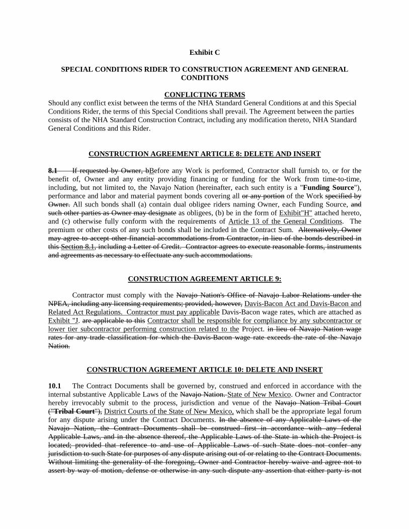
Exhibit C
SPECIAL CONDITIONS RIDER TO CONSTRUCTION AGREEMENT AND GENERAL CONDITIONS
CONFLICTING TERMS
Should any conflict exist between the terms of the NHA Standard General Conditions at and this Special Conditions Rider, the terms of this Special Conditions shall prevail. The Agreement between the parties consists of the NHA Standard Construction Contract, including any modification thereto, NHA Standard General Conditions and this Rider.
CONSTRUCTION AGREEMENT ARTICLE 8: DELETE AND INSERT
8.1 If requested by Owner, bBefore any Work is performed, Contractor shall furnish to, or for the benefit of, Owner and any entity providing financing or funding for the Work from time-to-time, including, but not limited to, the Navajo Nation (hereinafter, each such entity is a "Funding Source"), performance and labor and material payment bonds covering all or any portion of the Work specified by Owner. All such bonds shall (a) contain dual obligee riders naming Owner, each Funding Source, and such other parties as Owner may designate as obligees, (b) be in the form of Exhibit"H" attached hereto, and (c) otherwise fully conform with the requirements of Article 13 of the General Conditions. The premium or other costs of any such bonds shall be included in the Contract Sum. Alternatively, Owner may agree to accept other financial accommodations from Contractor, in lieu of the bonds described in this Section 8.1, including a Letter of Credit. Contractor agrees to execute reasonable forms, instruments and agreements as necessary to effectuate any such accommodations.
CONSTRUCTION AGREEMENT ARTICLE 9:
Contractor must comply with the Navajo Nation's Office of Navajo Labor Relations under the NPEA, including any licensing requirements; provided, however, Davis-Bacon Act and Davis-Bacon and Related Act Regulations. Contractor must pay applicable Davis-Bacon wage rates, which are attached as Exhibit "J. are applicable to this Contractor shall be responsible for compliance by any subcontractor or lower tier subcontractor performing construction related to the Project. in lieu of Navajo Nation wage rates for any trade classification for which the Davis-Bacon wage rate exceeds the rate of the Navajo Nation.
CONSTRUCTION AGREEMENT ARTICLE 10: DELETE AND INSERT
10.1 The Contract Documents shall be governed by, construed and enforced in accordance with the internal substantive Applicable Laws of the Navajo Nation. State of New Mexico. Owner and Contractor hereby irrevocably submit to the process, jurisdiction and venue of the Navajo Nation Tribal Court ("Tribal Court"), District Courts of the State of New Mexico, which shall be the appropriate legal forum for any dispute arising under the Contract Documents. In the absence of any Applicable Laws of the Navajo Nation, the Contract Documents shall be construed first in accordance with any federal Applicable Laws, and in the absence thereof, the Applicable Laws of the State in which the Project is located; provided that reference to and use of Applicable Laws of such State does not confer any jurisdiction to such State for purposes of any dispute arising out of or relating to the Contract Documents. Without limiting the generality of the foregoing, Owner and Contractor hereby waive and agree not to assert by way of motion, defense or otherwise in any such dispute any assertion that either party is not

2
subject to the personal jurisdiction of the Tribal Court, or that such dispute is brought in an inconvenient forum or that the venue therefor is improper.
10.2 Nothing in this agreement shall be interpreted as constituting a waiver, express or implied, of the sovereign immunity of the Navajo Nation. Furthermore, Owner hereby expressly reserves its exemption from levy or execution of judgments as set forth in 6 N.N.C § 623.
GENERAL CONDITIONS: DEFINITIONS APPLICABLE LAW: STRIKETHROUGH
"Applicable Law(s)" means the requirements of all laws, ordinances, codes, rules, regulations, executive orders, judicial opinions, and decisions of all governmental authorities having jurisdiction over the Project, the Site, the Work, or any part thereof, including, but not limited to, the Navajo Nation, federal, state, county and local authorities. Applicable Laws include, but are not limited to, as applicable, those relating to HUD, taxes, employment (including the Navajo Nation Business Activity Tax, 24 N.N.C. § 401, et seq.),, social security, unemployment, workers' compensation, wages (including the Navajo Preference in Employment Act, 15 N.N.C. § 601, et seq.), occupational health and safety, discrimination, disability, waters of the United States, land use, waste disposal, air, water, endangered species, groundwater, environmental contamination, toxic wastes, hazardous substances, oil, petrochemicals, pesticides, herbicides, building and construction codes and standards, and contracting licensing statutes and regulations.
GENERAL CONDITIONS ARTICLE 3: DELETE AND INSERT
3.01 As between the parties to the Agreement, Owner shall have title to all Plans and Specifications and other Contract Documents and unlimited rights with respect to any use thereof.
3.02 As to all persons other than Owner and Design Professional, the Plans and Specifications and other Contract Documents are instruments of service of the Owner. Contractor may retain one record set of such instruments of service. Neither Contractor nor any Subcontractor of any tier shall own or claim a copyright in such instruments of service, and, unless otherwise indicated, Owner shall be deemed the author of them or the author's assignee, and will retain all common law, statutory and other reserved rights in addition to the copyright. All copies of such instruments of service, except Contractor's record set, shall be returned or suitably accounted for to Owner, upon request, upon Final Completion.
GENERAL CONDITIONS ARTICLE 13: STRIKETHROUGH
13.01.01 Contractor and the Subcontractors of every tier shall purchase and maintain for the time periods provided herein, at Contractor's and such Subcontractors' sole cost and expense, insurance in the coverage, limits, and terms set forth as follows:
(a) Workmen's Compensation Insurance affording statutory coverage and containing not less than statutory limits for the state(s) in which the Work is being conducted, and Employer's Liability Insurance in the amount of not less than $1,000,000 each accident for bodily injury, $1,000,000 each employee for bodily injury by disease, and $1,000,000 policy limit for bodily injury by disease per person;
(b) Commercial General Liability ("CGL") Insurance with limits of liability of not less than $1,000,000 per occurrence and $5,000,000 annual aggregate. CGL insurance shall be written on an ISO occurrence form CG 00 01 1204 (or a substitute form providing equivalent coverage) and shall cover bodily injury and property damages arising from

3
premises operations, independent contractors, products-completed operations, personal and advertising injury and liability assumed under an insured contract (including tort liability of another assumed in a contract);
(c) Automobile Liability Insurance including coverage for owned, non-owned and hired autos in an amount not less than $1,000,000 per occurrence, combined single limit liability covering bodily injury and property damage; and
(d) Umbrella Insurance in the amount of $5,000,000 per occurrence.
13.01.02 Failure to comply with Section 13.01.01 shall be a material breach of the Agreement.
13.01.03 If any part of the Work is performed pursuant to a subcontract agreement, insurance shall be provided by or on behalf of Subcontractor(s) to cover the part of the Work each has contracted to perform and shall be maintained until Final Completion. The type of insurance required is as described herein, and shall cover the amounts as specified.
13.01.04 Certificates of Insurance evidencing the required coverages shall be submitted prior to the commencement of the Work. The original and all required updates shall be sent to the Owner's Representative.
13.01.05 Contractor's insurance shall:
(a) name the Indemnified Parties. Additional Insured under the CGL insurance using ISO additional insured endorsement CG 2037 0704 or a substitute providing equivalent coverage;
(b) state that Owner will be provided at least thirty (30) days’ advance written notice of a cancellation or modification of the insurance;
(c) apply as primary coverage without right of contribution from any other Owner insurance or self-insurance program;
(d) be provided by an insurance company authorized to issue insurance in New Mexico from a carrier having an A.M. Best Rating of at least A-.
13.01.06 The furnishing of the required Certificates of Insurance by Contractor shall in no way reduce Contractor's liabilities or obligations under the Agreement.
13.01.07 Contractor shall not violate, or permit to be violated, any conditions of any required insurance policies, and shall at all times satisfy the requirements of the insurance companies writing such policies.
13.01.08 If Contractor fails to furnish and maintain the insurance required herein or to furnish satisfactory evidence thereof, Owner shall have the right (but not the obligation) to procure and maintain the same for all parties on behalf of Contractor, at Contractor's cost and expense, and Contractor agrees to furnish all necessary information required to effect such insurance coverage.

4
13.02 OWNER'S INSURANCE
Owner shall pay for and maintain Owner's customary liability insurance. Owner may provide a "Builder Risk" policy. Insurance maintained by Owner is for the exclusive benefit of Owner and will not inure to the benefit of Contractor.
GENERAL CONDITIONS ARTICLE 17: STRIKETHROUGH
17.01 PROHIBITION AGAINST LIENS
Contractor hereby acknowledges that Applicable Laws prohibit Contractor and its Subcontractors from placing a lien on the Site. This prohibition shall be placed in all contracts Contractor enters into in connection with the Work performed under the Agreement.
17.02 EMPLOYMENT RIGHTS
Contractor shall meet with the Navajo Nation's Office of Navajo Labor Relations to discuss Contractor's obligations under the NPEA prior to performing Work under the Agreement.

Section 00 70 00
Division 00 Exhibit D Schedule of Values

CONTINUATION SHEET AIA DOCUMENT G703AIA Document G702, APPLICATION AND CERTIFICATE FOR PAYMENTcontaining CONTRACTOR'S signed Certification is attached.
PROJECT NAME: 0Period to: 1/0/1900 PROJECT NUMBER: 0
Date: 1/0/1900 APPLICATION NUMBER: ZERO (0)
Scheduled Value Previous Application
This Application: Work in Place Stored Materials Total Comp. and
Stored % Balance to Finish XX RETAINAGE
10000 General Requirements 0.00 0.00 0.00 0.00 0.00 0% 0.00 0.0024000 Demoliton 0.00 0.00 0.00 0.00 0.00 0% 0.00 0.0025000 Site Remediation 0.00 0.00 0.00 0.00 0.00 0% 0.00 0.0033000 Concrete 0.00 0.00 0.00 0.00 0.00 0% 0.00 0.0040000 Masonry 0.00 0.00 0.00 0.00 0.00 0% 0.00 0.0050000 Structural Metals 0.00 0.00 0.00 0.00 0.00 0% 0.00 0.0055000 Metal Fabrications 0.00 0.00 0.00 0.00 0.00 0% 0.00 0.0061000 Rough Carpentry 0.00 0.00 0.00 0.00 0.00 0% 0.00 0.0062000 Finish Carpentry 0.00 0.00 0.00 0.00 0.00 0% 0.00 0.0064000 Architectural Woodwork 0.00 0.00 0.00 0.00 0.00 0% 0.00 0.0071000 Waterproofing 0.00 0.00 0.00 0.00 0.00 0% 0.00 0.0072000 Thermal Protection 0.00 0.00 0.00 0.00 0.00 0% 0.00 0.0072500 Vapor Retarders 0.00 0.00 0.00 0.00 0.00 0% 0.00 0.0075000 Membrane Roofing 0.00 0.00 0.00 0.00 0.00 0% 0.00 0.0078000 Joint Protection 0.00 0.00 0.00 0.00 0.00 0% 0.00 0.0081000 Doors and Frames 0.00 0.00 0.00 0.00 0.00 0% 0.00 0.0084000 Storefront 0.00 0.00 0.00 0.00 0.00 0% 0.00 0.0085000 Windows and Screens 0.00 0.00 0.00 0.00 0.00 0% 0.00 0.0087000 Hardware 0.00 0.00 0.00 0.00 0.00 0% 0.00 0.0092200 Gypsum Board Assemblies 0.00 0.00 0.00 0.00 0.00 0% 0.00 0.0092500 Acrylic Stucco 0.00 0.00 0.00 0.00 0.00 0% 0.00 0.0095000 Ceilings 0.00 0.00 0.00 0.00 0.00 0% 0.00 0.0096000 Flooring 0.00 0.00 0.00 0.00 0.00 0% 0.00 0.0099000 Painting 0.00 0.00 0.00 0.00 0.00 0% 0.00 0.00
100000 Specialties 0.00 0.00 0.00 0.00 0.00 0% 0.00 0.00111200 Gates 0.00 0.00 0.00 0.00 0.00 0% 0.00 0.00112000 Commercial Equipment 0.00 0.00 0.00 0.00 0.00 0% 0.00 0.00113000 Residential Equipment 0.00 0.00 0.00 0.00 0.00 0% 0.00 0.00114000 Foodservice Equipment 0.00 0.00 0.00 0.00 0.00 0% 0.00 0.00122000 Window Blinds 0.00 0.00 0.00 0.00 0.00 0% 0.00 0.00123000 Casework 0.00 0.00 0.00 0.00 0.00 0% 0.00 0.00142000 Elevators 0.00 0.00 0.00 0.00 0.00 0% 0.00 0.00210000 Fire Supression 0.00 0.00 0.00 0.00 0.00 0% 0.00 0.00221000 Plumbing 0.00 0.00 0.00 0.00 0.00 0% 0.00 0.002E+06 Plumbing Fixtures 0.00 0.00 0.00 0.00 0.00 0% 0.00 0.00
230000 HVAC 0.00 0.00 0.00 0.00 0.00 0% 0.00 0.00260000 Electrical 0.00 0.00 0.00 0.00 0.00 0% 0.00 0.00270000 Communications 0.00 0.00 0.00 0.00 0.00 0% 0.00 0.00280000 Electronic Safety and Security 0.00 0.00 0.00 0.00 0.00 0% 0.00 0.00310000 Earthwork 0.00 0.00 0.00 0.00 0.00 0% 0.00 0.00320000 Exterior Improvements 0.00 0.00 0.00 0.00 0.00 0% 0.00 0.00330000 Utilities 0.00 0.00 0.00 0.00 0.00 0% 0.00 0.00
Closeout 0% 0.00 0.00 0.00 0.00 0.00 0% 0.00 0.00Mark Up 0% 0.00 0.00 0.00 0.00 0.00 0% 0.00 0.00NM GR Tax 0% 0.00 0.00 0.00 0.00 0.00 0% 0.00 0.00
TOTAL 0.00 0.00 0.00 0.00 0.00 0% 0.00 0.00
Change Orders
Change Order #0 0.00 0.00 0.00 0.00 0.00 0% 0.00 0.00
TOTAL 0.00 0.00 0.00 0.00 0.00 0.00 0.00 0.00

Division 00 01 00 to Division 00 33 00 Exhibit E Plans and Specifications

Project Plans and Specifications To Be Included in Construction Agreement Document

Division 00 00 00 Exhibit F Application for Payment

APPLICATION AND CERTIFICATE FOR PAYMENTOWNER: 0 PROJECT: 0 APPLICATION NO: ZERO (0) Distribution To:
0 0 PERIOD TO: 1/0/1900 OWNER FP0 0 PROJECT NO: ARCHITECT CN
PROJECT NO: 0 CONTRACTOR JC0 ARCHITECT: 0 CONTRACT DATE: GRT0 0
0
CONTRACT FOR : General Construction
CONTRACTOR'S APPLICATION FOR PAYMENT The undersigned Contractor certifies that to the best of the Contractor's knowledge, information andApplication is made for payment, as shown below, in connection with the Contract. belief the Work covered by this Application for Payment has been completed in accordanceContinuation Sheet is attached. with the Contract Documents, that all amounts have been paid by the Contractor for Work1. ORIGINAL CONTRACT SUM 0.00 for which previous Certificates for Payment were issued and payments received from the Owner, 2. Net Change by Change Orders 0.00 and that current payment shown herein is now due.3. CONTRACT SUM TO DATE (Line 1 +/-2) 0.00 CONTRACTOR: 04. TOTAL COMPLETED & STORED TO DATE 0.00
By: Date: 1/0/1900
5. RETAINAGE: , Project Managera. 0% of Completed Work 0.00 State of: NEW MEXICO
(Columns D + E on Continuation Sheet) County of: BERNALILLOb. 0% of Stored Materials 0.00 Subscribed and sworn to me before me
(Column F on Continuation Sheet) this 0ST day of 0 2000Total Retainage (Line 5a + 5b or 0.00
Notary Public:
6. TOTAL EARNED LESS RETAINAGE 0.00 My Commission expires: 6/26/2012
(Line 4 less Line 5 Total) ARCHITECT'S CERTIFICATE FOR PAYMENT7. LESS PREVIOUS CERTIFICATES FOR PAYMENT 0.00 (Line 6 from prior Certificate) In accordance with the Contract Documents, based on on-site observations and the data8. CURRENT PAYMENT DUE 0.00 comprising this application, the Architect certifies to the Owner that to the best of the9. BALANCE TO FINISH, INCLUDING RETAINAGE Architect's knowledge, information and belief the Work has progressed as indicated, the (Line 3 less Line 6) 0.00 quality of the Work is in accordance with the Contract Documents, and the Contractor
is entitled to payment of the AMOUNT CERTIFIED.AMOUNT CERTIFIED…….. $0.00
CHANGE ORDER SUMMARY ADDITIONS DEDUCTIONS Attach explanation if amount certified differs from the amount applied for. Initial all figuresTotal changes approved in on this Application and on the Continuation Sheet that are changed to conform to the amount certified.)previous months by Owner 0.00 0.00 ARCHITECT: 0Total approved this Month 0.00 0.00
TOTALS 0.00 0.00 By: Date:
NET CHANGES by Change Order 0.00 This certificate is not negotiable. The AMOUNT CERTIFIED is payable only to the Contractor
named herein. Issuance, payment and acceptance of payment are without prejudice to any rights of the
Owner or Contractor under this Contract. ()
0

CONTINUATION SHEET AIA DOCUMENT G703AIA Document G702, APPLICATION AND CERTIFICATE FOR PAYMENTcontaining CONTRACTOR'S signed Certification is attached.
PROJECT NAME: 0Period to: 1/0/1900 PROJECT NUMBER: 0
Date: 1/0/1900 APPLICATION NUMBER: ZERO (0)
Scheduled Value Previous Application
This Application: Work in Place Stored Materials Total Comp. and
Stored % Balance to Finish XX RETAINAGE
10000 General Requirements 0.00 0.00 0.00 0.00 0.00 0% 0.00 0.0024000 Demoliton 0.00 0.00 0.00 0.00 0.00 0% 0.00 0.0025000 Site Remediation 0.00 0.00 0.00 0.00 0.00 0% 0.00 0.0033000 Concrete 0.00 0.00 0.00 0.00 0.00 0% 0.00 0.0040000 Masonry 0.00 0.00 0.00 0.00 0.00 0% 0.00 0.0050000 Structural Metals 0.00 0.00 0.00 0.00 0.00 0% 0.00 0.0055000 Metal Fabrications 0.00 0.00 0.00 0.00 0.00 0% 0.00 0.0061000 Rough Carpentry 0.00 0.00 0.00 0.00 0.00 0% 0.00 0.0062000 Finish Carpentry 0.00 0.00 0.00 0.00 0.00 0% 0.00 0.0064000 Architectural Woodwork 0.00 0.00 0.00 0.00 0.00 0% 0.00 0.0071000 Waterproofing 0.00 0.00 0.00 0.00 0.00 0% 0.00 0.0072000 Thermal Protection 0.00 0.00 0.00 0.00 0.00 0% 0.00 0.0072500 Vapor Retarders 0.00 0.00 0.00 0.00 0.00 0% 0.00 0.0075000 Membrane Roofing 0.00 0.00 0.00 0.00 0.00 0% 0.00 0.0078000 Joint Protection 0.00 0.00 0.00 0.00 0.00 0% 0.00 0.0081000 Doors and Frames 0.00 0.00 0.00 0.00 0.00 0% 0.00 0.0084000 Storefront 0.00 0.00 0.00 0.00 0.00 0% 0.00 0.0085000 Windows and Screens 0.00 0.00 0.00 0.00 0.00 0% 0.00 0.0087000 Hardware 0.00 0.00 0.00 0.00 0.00 0% 0.00 0.0092200 Gypsum Board Assemblies 0.00 0.00 0.00 0.00 0.00 0% 0.00 0.0092500 Acrylic Stucco 0.00 0.00 0.00 0.00 0.00 0% 0.00 0.0095000 Ceilings 0.00 0.00 0.00 0.00 0.00 0% 0.00 0.0096000 Flooring 0.00 0.00 0.00 0.00 0.00 0% 0.00 0.0099000 Painting 0.00 0.00 0.00 0.00 0.00 0% 0.00 0.00
100000 Specialties 0.00 0.00 0.00 0.00 0.00 0% 0.00 0.00111200 Gates 0.00 0.00 0.00 0.00 0.00 0% 0.00 0.00112000 Commercial Equipment 0.00 0.00 0.00 0.00 0.00 0% 0.00 0.00113000 Residential Equipment 0.00 0.00 0.00 0.00 0.00 0% 0.00 0.00114000 Foodservice Equipment 0.00 0.00 0.00 0.00 0.00 0% 0.00 0.00122000 Window Blinds 0.00 0.00 0.00 0.00 0.00 0% 0.00 0.00123000 Casework 0.00 0.00 0.00 0.00 0.00 0% 0.00 0.00142000 Elevators 0.00 0.00 0.00 0.00 0.00 0% 0.00 0.00210000 Fire Supression 0.00 0.00 0.00 0.00 0.00 0% 0.00 0.00221000 Plumbing 0.00 0.00 0.00 0.00 0.00 0% 0.00 0.002E+06 Plumbing Fixtures 0.00 0.00 0.00 0.00 0.00 0% 0.00 0.00
230000 HVAC 0.00 0.00 0.00 0.00 0.00 0% 0.00 0.00260000 Electrical 0.00 0.00 0.00 0.00 0.00 0% 0.00 0.00270000 Communications 0.00 0.00 0.00 0.00 0.00 0% 0.00 0.00280000 Electronic Safety and Security 0.00 0.00 0.00 0.00 0.00 0% 0.00 0.00310000 Earthwork 0.00 0.00 0.00 0.00 0.00 0% 0.00 0.00320000 Exterior Improvements 0.00 0.00 0.00 0.00 0.00 0% 0.00 0.00330000 Utilities 0.00 0.00 0.00 0.00 0.00 0% 0.00 0.00
Closeout 0% 0.00 0.00 0.00 0.00 0.00 0% 0.00 0.00Mark Up 0% 0.00 0.00 0.00 0.00 0.00 0% 0.00 0.00NM GR Tax 0% 0.00 0.00 0.00 0.00 0.00 0% 0.00 0.00
TOTAL 0.00 0.00 0.00 0.00 0.00 0% 0.00 0.00
Change Orders
Change Order #0 0.00 0.00 0.00 0.00 0.00 0% 0.00 0.00
TOTAL 0.00 0.00 0.00 0.00 0.00 0.00 0.00 0.00

STORED MATERIAL RECAPAs of 1/0/1900
0
Phase # Invoice Amount
TOTAL STORED MATERIALS 0.000
0

THE STATE OF NEW MEXICOCOUNTY OF BERNALILLO
KNOW ALL MEN BY THESE PRESENTS: that the undersigned did furnish labor or materials or in its' capacity as General Contractor, did cause labor or materials to be furnished in connection with the construction of improvements on the following
0 County, New Mexico to wit:
Project # Upon receipt of the sum of $0.00and other good and valuable consideration, the undersigned will waive and release any mechanic's or materialmen's lien or claim or right of such lien, express or implied, constitutional, statutory, contractual or otherwise, against the aforementioned premises and any improvements now or hereafter located thereon which now exists or might otherwise arise on account of the labor ormaterials furnished by the undersigned in connection with the construction of improvements of the above mentioned premises. All labor and materials furnished and contracted for by the undersigned in connection with the construction of improvements on said premises through and including the date hereof have been paid for and there are now no unpaid claims for labor or materials against the improvements or the property, and the undersigned does hereby declare that all sums of money due for such labor and material have been fully paid and satisfied. The undersigned shall indemnify, defend, and hold the Owner of said premises harmless, for any and all liability, loss or damage that said Owner may suffer or sustain by reason or in consequence of, the failureor refusal of the undersigned to pay and discharge in full any claims for labor or materials furnished and contracted for by theundersigned that may be made against said premises and the improvements thereon or the Owner thereof. Should theundersigned fail or refuse to defend against any such claims, said Owner may conduct such defense at the expense of the undersigned, and in the event that the undersigned defaults in the payment of any sums that may become payable hereunder or breaches in the performance of any covenants contained herein, the undersigned shall pay to said Owner, on demand, any expenses incurred or paid by said Owner to enforce this Agreement, including attorney's fees and court costs. The undersignedrepresents and warrants that all sums paid or advanced by said Owner to it have been applied by the undersigned to pay and discharge all costs of labor and materials furnished and contracted for by the undersigned in connection with the construction of improvements on said premises, and the undersigned acknowledges that all sums paid or advanced by Owner to it are trust funds for the benefit of artisans, laborers, mechanics, contractors, subcontractors and materialmen who provided labor and materials to said premises and that it is a criminal offense to divert any of said sums to any other use unless and until all of said beneficiaries are paid in full.
EXECUTED this 0ST day of 0 , 2000 $0.00 paid to General contractor, Ltd. On this release.
BY:_______________________________________________ 0 ,Project Manager
STATE OF NEW MEXICOCOUNTY OF BERNALILLO (SEAL)
0ST day of 0 , 2000
Notary Public ______________________________________________ My commission expires 0
Conditional Waiver of Lien
$ZERO AND
Subscribed and sworn to before me this
described real property situated in
0 0

Division 00 Exhibit G Project Schedule

Contractor’s Project Schedule to be Included in Contract Documents Post Award

Division 00 Exhibit H Bonds

PERFORMANCE AND PAYMENT BOND Page 1 of 2
PERFORMANCE AND PAYMENT BOND
KNOW ALL MEN BY THESE PRESENTS: That we, __________________________________________________ __________________________ AS PRINCIPAL and ___________________________________________________ _______________________, AS SURETY, are held firmly bound unto
Community Area Resource Enterprise, Inc. (CARE 66) PO Box 4298
Gallup, NM 87305
Hereinafter called the “Owner” in the penal sum of __________________________________ ($__________________) Dollars, for the payment of which sum we bind ourselves, our heirs, executors, administrators, and successors, jointly and severally. WHEREAS, the Principal has entered into a certain Contract with the Owner, dated _______________________, 2010 a copy of which is hereto attached and made a part of hereof. NOW THEREFORE, the condition of this obligation is such that if the Principal shall in all respects fully perform the Contract and all duly authorized modifications thereof, during its original term and any extensions thereof that may be granted and during any guaranty period for which the Contract provides, and if the Principal shall fully satisfy all claims arising out of the prosecution of the work under the Contract and shall fully indemnify the Owner for all expenses which it may incur by reason of such claims, including its attorney’s fees and court costs, and if the Principal shall make full payment to all person supplying labor, services, materials, or equipment in the prosecution of the work under the Contract, in default of which such persons shall have a direct right of action hereupon; and if the Principal shall pay or cause to be paid all sales and use taxes payable as a result of the performance of the Contract as well as payment of gasoline and special motor fuels taxes in the performance of the Contract and all motor vehicle fees required for Contract, then this obligation shall be void; otherwise, it shall remain in full force and effect. No modification of the Contract or extension of neither the term thereof, nor any forbearance on the part of the Owner shall in any way release the Principal or the Surety from liability hereunder. Notice to the Surety of any such modification, extension, or forbearance is hereby waived. IN WITNESS WHEREOF, the aforesaid Principal and Surety have executed this instrument and affixed their seals hereto, this ___________day of ________________, 2010. WITNESS: (Seal) Individual Principal _________________________________ _________________________________________ Business Address _________________________________________ _________________________________ _________________________________________ WITNESS: (Seal) Individual Principal _________________________________ _________________________________________ Business Address _________________________________________ _________________________________ _________________________________________

PERFORMANCE AND PAYMENT BOND Page 2 of 2
ATTEST: (Seal) Corporate Principal ________________________________________ By: _________________________________________ Title: _______________________________________ ____________________________________________ Business Address ____________________________________________ ____________________________________________ ATTEST: (Seal) Corporate Principal ________________________________________ By: _________________________________________ Title: _______________________________________ ____________________________________________ Business Address ____________________________________________ ____________________________________________ The rate of premium on this bond is $_________________________________. The total amount of premium charges is $_____________________________________. (The above is to be filled in by Surety Company. Power-of-Attorney of person signing for the Surety Company must be attached).
CERTIFICATE AS TO CORPORATE PRINCIPAL I, ____________________________, certify that I am the Secretary of the corporation named as Principal in the a foregoing bond; and that __________________________________ who signed the said bond on behalf of the Principal, was then _________________________ of said corporation; that I know his signature there to is genuine; and that said bond was fully signed, sealed and attested for and in behalf of said corporation by authority of its governed body. By: ______________________________________ Affix Corporate Seal

Division 00 Exhibit I Change Order

Project: Date:
(name, address) Change Order No.:
Project No.:
Consultant: Contract Date:
(name, address) Contract Amount:
The Contract is changed as follows:
The original (Contract Sum)(GMP or MACC) was: $
Net changes by previously authorized Change Orders: $The (Contract Sum) (GMP or MACC) prior to this Change Order was: $The (Contract Sum) (GMP or MACC) will (increase) (decrease) by this Change Order in total amount of: $The new (Contract Sum) (GMP or MACC) including this Change Order will be: $
The contract time will be changed by the following number of days: ( ) daysThe date of completion as of the date of this Change Order is therefore:
Acknowledged by:
Sub-recipient Architect Contractor
By Authorized Representative By Authorized Representative By Authorized Representative
Title: Title: Title:
Date: Date: Date:
CHANGE ORDER
In my review of the above Owner(s)/Contractor's change proposal and proposed improvements, I find the costs are fair and reasonable and that all the proposed changes conform to the adopted building code and general industry practices.
Not valid until signed by the Sub-recipient/Owner, Contractor and NHA/TDHE
Contractor
Executive Director
Architect
Project Architect
Owner

Division 00 Exhibit J NHA Wage Rate Determination
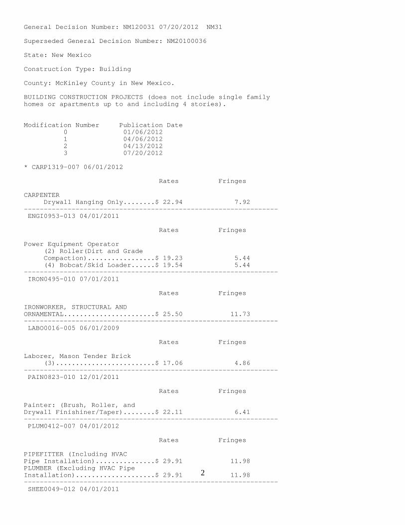
2
General Decision Number: NM120031 07/20/2012 NM31 Superseded General Decision Number: NM20100036 State: New Mexico Construction Type: Building County: McKinley County in New Mexico. BUILDING CONSTRUCTION PROJECTS (does not include single family homes or apartments up to and including 4 stories). Modification Number Publication Date 0 01/06/2012 1 04/06/2012 2 04/13/2012 3 07/20/2012 * CARP1319-007 06/01/2012 Rates Fringes CARPENTER Drywall Hanging Only........$ 22.94 7.92 ---------------------------------------------------------------- ENGI0953-013 04/01/2011 Rates Fringes Power Equipment Operator (2) Roller(Dirt and Grade Compaction).................$ 19.23 5.44 (4) Bobcat/Skid Loader......$ 19.54 5.44 ---------------------------------------------------------------- IRON0495-010 07/01/2011 Rates Fringes IRONWORKER, STRUCTURAL AND ORNAMENTAL.......................$ 25.50 11.73 ---------------------------------------------------------------- LABO0016-005 06/01/2009 Rates Fringes Laborer, Mason Tender Brick (3).........................$ 17.06 4.86 ---------------------------------------------------------------- PAIN0823-010 12/01/2011 Rates Fringes Painter: (Brush, Roller, and Drywall Finishiner/Taper)........$ 22.11 6.41 ---------------------------------------------------------------- PLUM0412-007 04/01/2012 Rates Fringes PIPEFITTER (Including HVAC Pipe Installation)...............$ 29.91 11.98 PLUMBER (Excluding HVAC Pipe Installation)....................$ 29.91 11.98 ---------------------------------------------------------------- SHEE0049-012 04/01/2011
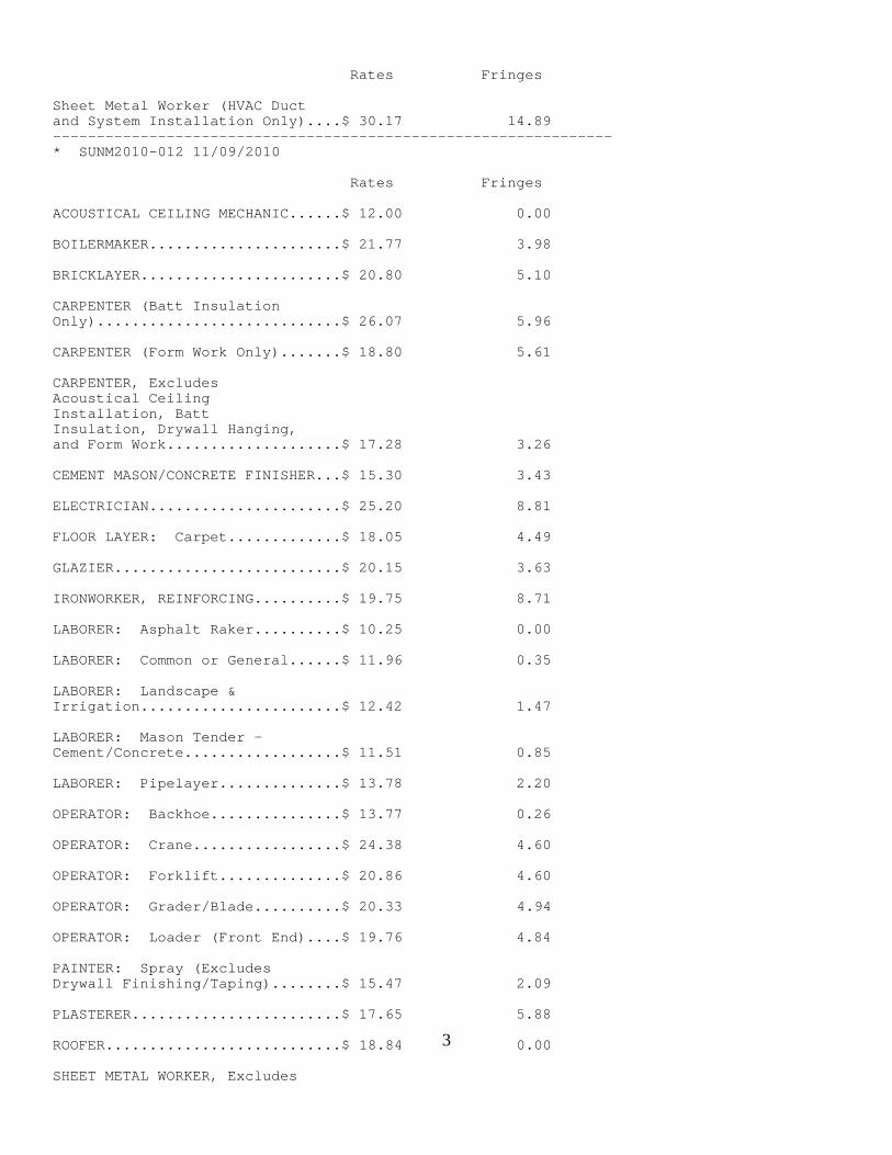
3
Rates Fringes Sheet Metal Worker (HVAC Duct and System Installation Only)....$ 30.17 14.89 ---------------------------------------------------------------- * SUNM2010-012 11/09/2010 Rates Fringes ACOUSTICAL CEILING MECHANIC......$ 12.00 0.00 BOILERMAKER......................$ 21.77 3.98 BRICKLAYER.......................$ 20.80 5.10 CARPENTER (Batt Insulation Only)............................$ 26.07 5.96 CARPENTER (Form Work Only).......$ 18.80 5.61 CARPENTER, Excludes Acoustical Ceiling Installation, Batt Insulation, Drywall Hanging, and Form Work....................$ 17.28 3.26 CEMENT MASON/CONCRETE FINISHER...$ 15.30 3.43 ELECTRICIAN......................$ 25.20 8.81 FLOOR LAYER: Carpet.............$ 18.05 4.49 GLAZIER..........................$ 20.15 3.63 IRONWORKER, REINFORCING..........$ 19.75 8.71 LABORER: Asphalt Raker..........$ 10.25 0.00 LABORER: Common or General......$ 11.96 0.35 LABORER: Landscape & Irrigation.......................$ 12.42 1.47 LABORER: Mason Tender - Cement/Concrete..................$ 11.51 0.85 LABORER: Pipelayer..............$ 13.78 2.20 OPERATOR: Backhoe...............$ 13.77 0.26 OPERATOR: Crane.................$ 24.38 4.60 OPERATOR: Forklift..............$ 20.86 4.60 OPERATOR: Grader/Blade..........$ 20.33 4.94 OPERATOR: Loader (Front End)....$ 19.76 4.84 PAINTER: Spray (Excludes Drywall Finishing/Taping)........$ 15.47 2.09 PLASTERER........................$ 17.65 5.88 ROOFER...........................$ 18.84 0.00 SHEET METAL WORKER, Excludes
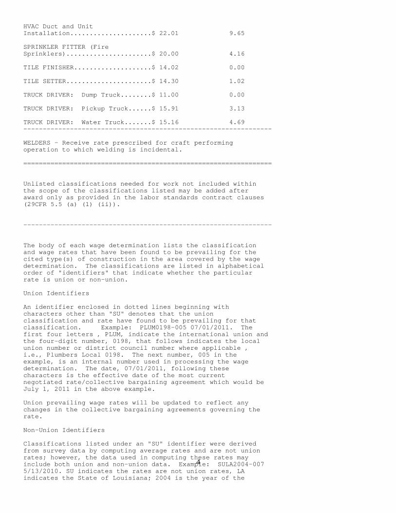
4
HVAC Duct and Unit Installation.....................$ 22.01 9.65 SPRINKLER FITTER (Fire Sprinklers)......................$ 20.00 4.16 TILE FINISHER....................$ 14.02 0.00 TILE SETTER......................$ 14.30 1.02 TRUCK DRIVER: Dump Truck........$ 11.00 0.00 TRUCK DRIVER: Pickup Truck......$ 15.91 3.13 TRUCK DRIVER: Water Truck.......$ 15.16 4.69 ---------------------------------------------------------------- WELDERS - Receive rate prescribed for craft performing operation to which welding is incidental. ================================================================ Unlisted classifications needed for work not included within the scope of the classifications listed may be added after award only as provided in the labor standards contract clauses (29CFR 5.5 (a) (1) (ii)). ---------------------------------------------------------------- The body of each wage determination lists the classification and wage rates that have been found to be prevailing for the cited type(s) of construction in the area covered by the wage determination. The classifications are listed in alphabetical order of "identifiers" that indicate whether the particular rate is union or non-union. Union Identifiers An identifier enclosed in dotted lines beginning with characters other than "SU" denotes that the union classification and rate have found to be prevailing for that classification. Example: PLUM0198-005 07/01/2011. The first four letters , PLUM, indicate the international union and the four-digit number, 0198, that follows indicates the local union number or district council number where applicable , i.e., Plumbers Local 0198. The next number, 005 in the example, is an internal number used in processing the wage determination. The date, 07/01/2011, following these characters is the effective date of the most current negotiated rate/collective bargaining agreement which would be July 1, 2011 in the above example. Union prevailing wage rates will be updated to reflect any changes in the collective bargaining agreements governing the rate. Non-Union Identifiers Classifications listed under an "SU" identifier were derived from survey data by computing average rates and are not union rates; however, the data used in computing these rates may include both union and non-union data. Example: SULA2004-007 5/13/2010. SU indicates the rates are not union rates, LA indicates the State of Louisiana; 2004 is the year of the

5
survey; and 007 is an internal number used in producing the wage determination. A 1993 or later date, 5/13/2010, indicates the classifications and rates under that identifier were issued as a General Wage Determination on that date. Survey wage rates will remain in effect and will not change until a new survey is conducted. ---------------------------------------------------------------- WAGE DETERMINATION APPEALS PROCESS 1.) Has there been an initial decision in the matter? This can be: * an existing published wage determination * a survey underlying a wage determination * a Wage and Hour Division letter setting forth a position on a wage determination matter * a conformance (additional classification and rate) ruling On survey related matters, initial contact, including requests for summaries of surveys, should be with the Wage and Hour Regional Office for the area in which the survey was conducted because those Regional Offices have responsibility for the Davis-Bacon survey program. If the response from this initial contact is not satisfactory, then the process described in 2.) and 3.) should be followed. With regard to any other matter not yet ripe for the formal process described here, initial contact should be with the Branch of Construction Wage Determinations. Write to: Branch of Construction Wage Determinations Wage and Hour Division U.S. Department of Labor 200 Constitution Avenue, N.W. Washington, DC 20210 2.) If the answer to the question in 1.) is yes, then an interested party (those affected by the action) can request review and reconsideration from the Wage and Hour Administrator (See 29 CFR Part 1.8 and 29 CFR Part 7). Write to: Wage and Hour Administrator U.S. Department of Labor 200 Constitution Avenue, N.W. Washington, DC 20210 The request should be accompanied by a full statement of the interested party's position and by any information (wage payment data, project description, area practice material, etc.) that the requestor considers relevant to the issue. 3.) If the decision of the Administrator is not favorable, an interested party may appeal directly to the Administrative Review Board (formerly the Wage Appeals Board). Write to: Administrative Review Board U.S. Department of Labor 200 Constitution Avenue, N.W. Washington, DC 20210 4.) All decisions by the Administrative Review Board are final. ================================================================

6
END OF GENERAL DECISION

Division 00 Exhibit K: Supplemental Conditions for Deductive Alternatives #------- and #------ (for ARRA & EPA Funded Projects)
(12-11-09)
New Mexico Environment Department
UNITED STATES ENVIRONMENTAL PROTECTION AGENCYREGION 6
Supplemental ConditionsFor
Federally Assisted Water and/or Wastewater Infrastructuresunder the
American Recovery and Reinvestment Act of 2009 (P.L. 111-5)
REPRODUCTION OF THIS GUIDANCESHOULD BE ON COLORED PAPER,PREFERABLY PINK
FORMS THAT NEED TO BE SUBMITTED WITH BIDS
General Requirements
1. EPA Form 5700-49, Certification Regarding Debarment, Suspension, and Other Responsibility Matters
2. ARRA-211, Certifications Regarding Contracts under Equal Opportunity Clause and
Nonsegregated Facilities.
Davis-Bacon Certification
3. ARRA-315, ARRA Davis-Bacon Certification
Buy American 4. ARRA-311, Bidder’s Certification in Compliance with “Buy American Provisions”
of ARRA. 5. ARRA-314, Contractor’s Acknowledgment in Compliance with “Buy American
Provisions” of ARRA
Disadvantaged Business Enterprise
6. EPA Form 6100-4, DBE Subcontractor utilization form 7. ARRA 215, MBE/WBE/SBRA Utilization Information Sheet
Disadvantaged Business Enterprise to be provided after award of contract
8. EPA Form 6100-2, DBE Subcontractor Participation Form
9. EPA Form 6100-3, DBE Subcontractor Performance Form
Labor Standards Certification form to be submitted with every pay application
10. EPA Form 214-Labor Standards Certification

WEB SITES AND OTHER MATERIALS
1. Copeland Anti-Kickback, 29 CFR Part 3 http://www.dol.gov/dol/allcfr/esa/title_29/Part_3/toc.htm
2. Labor Standards and Davis Bacon, 29 CFR Parts 4, 5 & 6
http://www.dol.gov/dol/allcfr/esa/title_29/Part_4/toc.htm http://www.dol.gov/dol/allcfr/esa/title_29/Part_5/toc.htm http://www.dol.gov/dol/allcfr/esa/title_29/Part_6/toc.htm
3. Equal Employment Opportunity, 41 CFR Part 60
http://www.dol.gov/DOL/allcfr/esa/Title_41/Chapter_60.htm
4. Nondiscrimination, 40 CFR Part 7 http://www.epa.gov/ocr/docs/40p0007.pdf
5. Buy American Memo - 4/28/09:
http://www.epa.gov/ogd/forms/Buy_Am.pdf
6. Substantial Transformation http://www.epa.gov/water/eparecovery/docs/10_23_09_Substantial_Transformation_memo_Final.pdf
7. All other ARRA info (including reporting)
http://www.epa.gov/ow/eparecovery/
8. Uniform Administrative Requirements, 40 CFR Part 31 http://ecfr.gpoaccess.gov/cgi/t/text/text-idx?c=ecfr&tpl=/ecfrbrowse/Title40/40cfr31_main_02.tpl
9. OMB Circular A-133
http://www.whitehouse.gov/omb/assets/omb/circulars/a133/a133.pdf http://www.whitehouse.gov/omb/rewrite/circulars/a133_compliance/08/08toc.html http://www.whitehouse.gov/omb/assets/a133_compliance/app_7.pdf
10. Debarment, 40 CFR Part 32
http://ecfr.gpoaccess.gov/cgi/t/text/text-idx?c=ecfr&tpl=/ecfrbrowse/Title40/40cfr32_main_02.tpl
11. Disadvantaged Business Enterprise, 40 CFR Part 33 http://ecfr.gpoaccess.gov/cgi/t/text/text- idx?c=ecfr&sid=a109cc335a7c0f1204882809791c7a1f&rgn=div5&view=text&node=40:1.0.1.2.30&idno=40
12. Reissuance of NPDES General Permits for Storm Water Discharges from Construction Sites in Region 6-
Federal Register http://www.epa.gov/region6/6en/w/sw/swcon98.pdf
13. WH347 (Davis-Bacon Payroll)
http://www.dol.gov/whd/forms/wh347.pdf
14. Standard Form 1445 (Davis Bacon-Interview) http://contacts.gsa.gov/webforms.nsf/0/12BF5D0E2DC4484685256CBC0062F375/$file/sf1445_e.pdf
15. ARRA Wage Rate Document—Attached
16. ARRA Buy American Statement—Attached
17. Model Contract Clauses—Attached
18. NPDES Bypass Policy—Attached
19. Federal Cross-Cutters—Attached

Wage Rate Requirements
of The American Recovery and Reinvestment Act of 2009 (ARRA)
Section 1606 of the ARRA requires that all laborers and mechanics employed by
contractors and subcontractors on projects funded directly by or assisted in whole or in part by and through the Federal Government pursuant to this ARRA shall be paid wages at rates not less than those prevailing on projects of a character similar in the locality as determined by the Secretary of Labor in accordance with subchapter IV of chapter 31 of title 40, United States Code. With respect to the labor standards specified in this section, the Secretary of Labor shall have the authority and functions set forth in Reorganization Plan Numbered 14 of 1950 (64 Stat. 1267; 5 U.S.C. App.) and section 3145 of title 40, United States Code.
The requirements of paying the wages to all laborers and mechanics at rates not less than the prevailing rates are also known as "the Davis-Bacon and Related Act Requirements." All rulings and interpretations of the Davis-Bacon and Related Acts contained in 29 CFR Parts 1, 3, and 5 are herein incorporated by reference in this contact. Portions of 29 CFR Parts 3, 4, 5 and 6 have also been included. The prime Contractor and its Subcontractors must pay their laborers and mechanics employees at wage rates listed in other parts of this specifications and relevant addenda if any.
The Contractor and its Subcontractors must also comply with applicable labor standards as set forth in 40 CFR 31.36 (i)(3), (4) and (6). Therefore, the responsive and responsible bidder must certify the compliance with applicable labor standards as Form ARRA-211 as provided in subsequent page or equivalent. In addition, the acceptable prime Contractor must also certify the compliance with the labor standards and prevailing wage requirements as Form ARRA-214 as provided in the following subsequent page or equivalent.
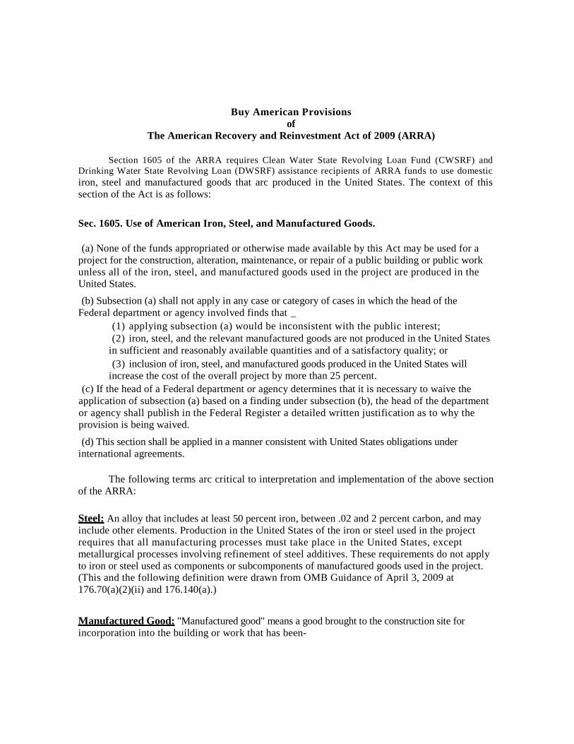
Buy American Provisions of
The American Recovery and Reinvestment Act of 2009 (ARRA)
Section 1605 of the ARRA requires Clean Water State Revolving Loan Fund (CWSRF) and Drinking Water State Revolving Loan (DWSRF) assistance recipients of ARRA funds to use domestic iron, steel and manufactured goods that arc produced in the United States. The context of this section of the Act is as follows:
Sec. 1605. Use of American Iron, Steel, and Manufactured Goods.
(a) None of the funds appropriated or otherwise made available by this Act may be used for a
project for the construction, alteration, maintenance, or repair of a public building or public work unless all of the iron, steel, and manufactured goods used in the project are produced in the United States.
(b) Subsection (a) shall not apply in any case or category of cases in which the head of the Federal department or agency involved finds that _
(1) applying subsection (a) would be inconsistent with the public interest; (2) iron, steel, and the relevant manufactured goods are not produced in the United States
in sufficient and reasonably available quantities and of a satisfactory quality; or (3) inclusion of iron, steel, and manufactured goods produced in the United States will
increase the cost of the overall project by more than 25 percent. (c) If the head of a Federal department or agency determines that it is necessary to waive the
application of subsection (a) based on a finding under subsection (b), the head of the department or agency shall publish in the Federal Register a detailed written justification as to why the provision is being waived.
(d) This section shall be applied in a manner consistent with United States obligations under international agreements.
The following terms arc critical to interpretation and implementation of the above section
of the ARRA: Steel: An alloy that includes at least 50 percent iron, between .02 and 2 percent carbon, and may include other elements. Production in the United States of the iron or steel used in the project requires that all manufacturing processes must take place i n the United States, except metallurgical processes involving refinement of steel additives. These requirements do not apply to iron or steel used as components or subcomponents of manufactured goods used in the project. (This and the following definition were drawn from OMB Guidance of April 3, 2009 at 176.70(a)(2)(ii) and 176.140(a).)
Manufactured Good: "Manufactured good" means a good brought to the construction site for incorporation into the building or work that has been-

(1) Processed into a specific form and shape; or (2) combined with other raw material to create a material that has different properties
than the properties of the raw materials. There is no requirement with regard to the origin of components or subcomponents in manufactured goods as long as the manufacture of goods occurs in the United States.
Reasonably Available Quantity: The quantity of iron, steel, or the relevant manufactured good is available or will be available at the time needed and place needed, and in the proper form or specification as specified in the project plans and design.
Satisfactory Quality: The quality of iron, steel, or the relevant manufactured good as specified in the project plans and designs.
Assistance Recipient: A borrower or grantee that receives funding from a State CWSRF or DWSRF program.
Unless the EPA grants a waiver from the "Buy American Provisions" by an appropriate process as described in EPA Memorandum, ARRA 09-1, dated April 28, 2009, the responsible and responsive bidder must certify its bid meets the "Buy American Provisions" as indicated in the Form ARRA-311 as provided in the subsequent page or equivalent format. The acceptable contractor must acknowledge requirements of the "Buy American Provisions" as indicated in Form ARRA-314 as provided in the next subsequent page or equivalent format.

1
UNITED STATES ENVIRONMENTAL PROTECTION AGENCYRegion 6
MODEL CONTRACT CLAUSE
Recipients must ensure that, when appropriate, the following clauses or their equivalent areincluded in each contract.
1. SUPERSESSION
The recipient and the contractor agree that this and other appropriate clauses in 40 CFR 31.36(i)apply to that work eligible for EPA assistance to be performed under this contract and that theseclauses supersede any conflicting provisions of this contract.
2. PRIVITY OF CONTRACT
This contract is expected to be funded in part with funds from the U.S. Environmental ProtectionAgency. Neither the United States nor any of its departments, agencies or employees is, or willbe, a party to this contract or any lower tier contract. This contract is subject to the applicableEPA procurement regulations in effect on the date of the assistance award for this project.
3. CHANGES
a. The following clause applies only to contracts for construction.
1. The recipient may at any time, without notice to any surety, by written order, make anychange in the work within the general scope of the contract, including but not limited to changes:
i. In the specifications (including drawings and designs);ii. In the time, method or manner of performance of the work;iii. In the recipient-furnished facilities, equipment, materials, services or site, oriv. Directing acceleration in the performance of the work.
2. A change order shall also be any other written order (including direction, instruction,interpretation or determination) from the recipient which causes any change, provided thecontractor gives the recipient written notice stating the date, circumstances and source of theorder and that the contractor regards the order as a change order.3. Except as provided in this clause, no order, statement or conduct of the recipient shall betreated as a change under this clause or entitle the contractor to an equitable adjustment.4. If any change under this clause causes an increase or decrease in the contractor's cost or thetime required to perform any part of the work under this contract, whether or not changed by anyorder, the recipient shall make an equitable adjustment and modify the contract in writing.Except for claims based on defective specifications, no claim for any change under paragraph(a)(2) above shall be allowed for any costs incurred more than 20 days before the contractorgives written notice as required in paragraph (a)(2). In the case of defective specifications forwhich the recipient is responsible, the equitable adjustment shall include any increased cost the
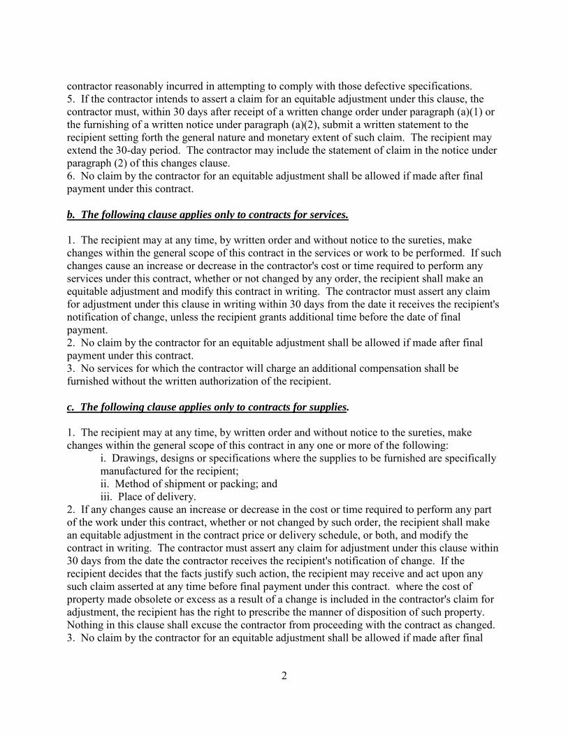
2
contractor reasonably incurred in attempting to comply with those defective specifications.5. If the contractor intends to assert a claim for an equitable adjustment under this clause, thecontractor must, within 30 days after receipt of a written change order under paragraph (a)(1) orthe furnishing of a written notice under paragraph (a)(2), submit a written statement to therecipient setting forth the general nature and monetary extent of such claim. The recipient mayextend the 30-day period. The contractor may include the statement of claim in the notice underparagraph (2) of this changes clause.6. No claim by the contractor for an equitable adjustment shall be allowed if made after finalpayment under this contract.
b. The following clause applies only to contracts for services.
1. The recipient may at any time, by written order and without notice to the sureties, makechanges within the general scope of this contract in the services or work to be performed. If suchchanges cause an increase or decrease in the contractor's cost or time required to perform anyservices under this contract, whether or not changed by any order, the recipient shall make anequitable adjustment and modify this contract in writing. The contractor must assert any claimfor adjustment under this clause in writing within 30 days from the date it receives the recipient'snotification of change, unless the recipient grants additional time before the date of finalpayment.2. No claim by the contractor for an equitable adjustment shall be allowed if made after finalpayment under this contract.3. No services for which the contractor will charge an additional compensation shall befurnished without the written authorization of the recipient.
c. The following clause applies only to contracts for supplies.
1. The recipient may at any time, by written order and without notice to the sureties, makechanges within the general scope of this contract in any one or more of the following:
i. Drawings, designs or specifications where the supplies to be furnished are specificallymanufactured for the recipient;ii. Method of shipment or packing; andiii. Place of delivery.
2. If any changes cause an increase or decrease in the cost or time required to perform any partof the work under this contract, whether or not changed by such order, the recipient shall makean equitable adjustment in the contract price or delivery schedule, or both, and modify thecontract in writing. The contractor must assert any claim for adjustment under this clause within30 days from the date the contractor receives the recipient's notification of change. If therecipient decides that the facts justify such action, the recipient may receive and act upon anysuch claim asserted at any time before final payment under this contract. where the cost ofproperty made obsolete or excess as a result of a change is included in the contractor's claim foradjustment, the recipient has the right to prescribe the manner of disposition of such property.Nothing in this clause shall excuse the contractor from proceeding with the contract as changed.3. No claim by the contractor for an equitable adjustment shall be allowed if made after final

3
payment under this contract.
4. DIFFERING SITE CONDITIONS
The following clause applies only to construction contracts.
a. The contractor shall promptly, and before such conditions are disturbed, notify the recipient inwriting of:
1. Subsurface or latent physical conditions at the site differing materially from thoseindicated in this contract, or2. Unknown physical conditions at the site, of an unusual nature, differing materiallyfrom those ordinarily encountered and generally recognized as inhering in work of thecharacter provided for in this contract.
b. The recipient shall promptly investigate the conditions. If it finds that conditions materiallydiffer and will cause an increase or decrease in the contractor's cost or the time required toperform any part of the work under this contract, whether or not changed as a result of suchconditions, the recipient shall make an equitable adjustment and modify the contract in writing.c. No claim of the contractor under this clause shall be allowed unless the contractor has giventhe notice required in paragraph (a) of this clause. However, the recipient may extend the timeprescribed in paragraph (a).d. No claim by the contractor for an equitable adjustment shall be allowed if asserted after finalpayment under this contract.
5. SUSPENSION OF WORK
The following clause applies only to construction contracts.
a. The recipient may order the contractor in writing to suspend, delay or interrupt all or any partof the work for such period of time as the recipient may determine to be appropriate for theconvenience of the recipient.b. If the performance of all or any part of the work is suspended, delayed or interrupted for anunreasonable period of time by an act of the recipient in administration of this contract, or by therecipient's failure to act within the time specified in this contract (or if no time is specified,within a reasonable time), the recipient shall make an adjustment for any increase in the cost ofperformance of this contract (excluding profit) necessarily caused by such unreasonablesuspension, delay or interruption and modify the subagreement in writing. However, noadjustment shall be made under this clause for any suspension, delay or interruption to the extent(1) that performance would have been so suspended, delayed or interrupted by any other cause,including the fault or negligence of the contractor, or (2) for which an equitable adjustment isprovided for or excluded under any other provision of this contract.c. No claim under this clause shall be allowed (1) for any costs incurred more than 20 daysbefore the contractor notified the recipient in writing of the act, or failure to act, involved (thisrequirement does not apply to a claim resulting from a suspension order), and (2) unless theamount claimed is asserted in writing as soon as practicable after the termination of such

4
suspension, delay or interruption, but not later than the date of final payment under the contract.
6. TERMINATION
The following clause applies only to contracts over $10,000.
a. This contract may be terminated in whole or in part in writing by either party in the event ofsubstantial failure by the other party to fulfill its obligations under this contract through no faultof the terminating party, provided that no termination may be effected unless the other party isgiven (1) not less than ten (10) calendar days' written notice (delivered by certified mail, returnreceipt requested) of intent to terminate, and (2) an opportunity for consultation with theterminating party prior to termination.b. This contract may be terminated in whole or in partin writing by the recipient for its convenience, provided that the contractor is given (1) not lessthan ten (10) calendar days' written notice (delivered by certified mail, return receipt requested)of intent to terminate, and (2) an opportunity for consultation with the terminating party prior totermination.c. If termination for default is effected by the recipient, an equitable adjustment in the priceprovided for in this contract shall be made, but (1) no amount shall be allowed for anticipatedprofit on unperformed services or other work, and (2) any payment due to the contractor at thetime of termination may be adjusted to cover any additional costs to the recipient because of thecontractor's default. If termination for default is effected by the contractor, or if termination forconvenience is effected by the recipient, the equitable adjustment shall include a reasonableprofit for services or other work performed. The equitable adjustment for any termination shallprovide for payment to the contractor for services rendered and expenses incurred prior to thetermination, in addition to termination settlement costs reasonably incurred by the contractorrelating to commitments which had become firm prior to the termination.d. Upon receipt of a termination action under paragraphs (a) or (b) above, the contractor shall(1) promptly discontinue all affected work (unless the notice directs otherwise), and (2) deliveror otherwise make available to the recipient all data, drawings, specifications, reports, estimates,summaries and such other information and materials as may have been accumulated by thecontractor in performing this contract, whether completed or in process.e. Upon termination under paragraphs (a) or (b) above, the recipient may take over the work andmay award another party a contract to complete the work under this contract.f. If, after termination for failure of the contractor to fulfill contractual obligations, it isdetermined that the contractor had not failed to fulfill contractual obligations, the terminationshall be deemed to have been for the convenience of the recipient. In such event, adjustment ofthe subagreement price shall be made as provided in paragraph (c) of this clause.
7. REMEDIES
This clause applies only to contracts over $25,000.
Unless otherwise provided in this contract, all claims, counter-claims, disputes and other matters

5
in question between the recipient and the contractor arising out of, or relating to, this contract orthe breach of it will be decided, if the parties mutually agree, by arbitration, mediation, or otheralternative dispute resolution mechanism; or in a court of competent jurisdiction within the Statein which the recipient is located.
8. PRICE REDUCTION FOR DEFECTIVE COST OR PRICING DATA
NOTE - The following clause applies to (1) any contract negotiated between the recipient and itscontractor in excess of $100,000; (2) negotiated contract amendments or change orders in excessof $100,000 affecting the price of a formally advertised, competitively awarded, fixed pricecontract, or (3) any lower tier contract or purchase order in excess of $100,000 under a contractother than a formally advertised, competitively awarded, fixed price contract. This clause doesnot apply to contracts awarded on the basis of effective price competition.
a. The contractor and subcontractor, where appropriate, assure that the cost and pricing datasubmitted for evaluation with respect to negotiation of prices for negotiated contracts, lower tiercontracts and change orders is based on current, accurate and complete data supported by theirbooks and records. If the recipient or EPA determines that any price (including profit)negotiated in connection with this contract, lower tier contract or amendment thereunder wasincreased by any significant sums because the data provided was incomplete, inaccurate or notcurrent at the time of submission, then such price or cost or profit shall be reduced accordinglyand the recipient shall modify the contract in writing to reflect such action.b. Failure to agree on a reduction shall be subject to the remedies clause of this contract.
NOTE - Since the contract is subject to reduction under this clause by reason of defective cost orpricing data submitted in connection with lower tier contracts, the contractor may wish to includea clause in each lower tier contract requiring the lower tier contractor to appropriately indemnifythe contractor. It is expected that any lower tier contractor subject to such indemnification willgenerally require substantially similar indemnification for defective cost and pricing datasubmitted by lower tier contractors.
9. AUDIT; ACCESS TO RECORDS
a. The contractor shall maintain books, records, documents and other evidence directly pertinentto performance on EPA funded work under this contract in accordance with generally acceptedaccounting principles and practices consistently applied, and the applicable EPA regulations ineffect on the date of execution of this contract. The contractor shall also maintain the financialinformation and data used in the preparation or support of any cost submission required underapplicable regulations for negotiated contracts or change orders and a copy of the cost summarysubmitted to the recipient. The United States Environmental Protection Agency, the ComptrollerGeneral of the United States, the United States Department of Labor, the recipient, and [theState] or any of their authorized representatives shall have access to all such books, records,documents and other evidence for the purpose of inspection, audit and copying during normalbusiness hours. The contractor will provide proper facilities for such access and inspection.

6
b. If this is a fixed price contract awarded through sealed bidding or otherwise on the basis ofeffective price competition, the contractor agrees to make paragraphs (a) through (g) of thisclause applicable to all negotiated change orders and contract amendments affecting the contractprice. In the case of all other types of prime contracts, the contractor agrees to make paragraphs(a) through (g) applicable to all contract awards in excess of $10,000, at any tier, and to makeparagraphs (a) through (g) of this clause applicable to all change orders directly related to projectperformance.c. Audits conducted under this provision shall be in accordance with generally accepted auditingstandards and with established procedures and guidelines of the reviewing or audit agency(ies).d. The contractor agrees to disclose all information and reports resulting from access to recordsunder paragraphs (a) and (b) of this clause to any of the agencies referred to in paragraph (a).e. Records under paragraphs (a) and (b) above shall be maintained by the contractor duringperformance on EPA assisted work under this contract and for the time periods specified in 40CFR part 31. In addition, those records which relate to any controversy arising under an EPAassistance agreement, litigation, the settlement of claims arising out of such performance or tocosts or items to which an audit exception has been taken shall be maintained by the contractorfor the time periods specified in 40 CFR part 31.f. Access to records is not limited to the required retention periods. The authorizedrepresentatives designated in paragraph (a) of this clause shall have access to records at anyreasonable time for as long as the records are maintained.g This right of access clause applies to financial records pertaining to all contracts (except forfixed price contracts awarded through sealed bidding or otherwise on the basis of effective pricecompetition) and all contract change orders regardless of the type of contract, and all contractamendments regardless of the type of contract. In addition this right of access applies to allrecords pertaining to all contracts, contract change orders and contract amendments:
1. To the extent the records pertain directly to contract performance;2. If there is any indication that fraud, gross abuse or corrupt practices may be involved;or3. If the subagreement is terminated for default or for convenience.
10. COVENANT AGAINST CONTINGENT FEES
The contractor assures that no person or selling agency has been employed or retained to solicitor secure this contract upon an agreement or understanding for a commission, percentage,brokerage or contingent fee excepting bona fide employees or bona fide established commercialor selling agencies maintained by the contractor for the purpose of securing business. For breachor violation of this assurance, the recipient shall have the right to annul this agreement withoutliability or, at its discretion, to deduct from the contract price or consideration, or otherwiserecover the full amount of such commission, percentage, brokerage or contingent fee.
11. GRATUITIES
a. If the recipient finds after a notice and hearing that the contractor or any of the contractor'sagents or representatives offered or gave gratuities (in the form of entertainment, gifts or

7
otherwise) to any official, employee or agent of the recipient, the State or EPA in an attempt tosecure a contract or favorable treatment in awarding, amending or making any determinationsrelated to the performance of this contract, the recipient may, by written notice to the contractor,terminate this contract. The recipient may also pursue other rights and remedies that the law orthis contract provides.b. In the event this contract is terminated as provided in paragraph (a), the recipient may pursuethe same remedies against the contractor as it could pursue in the event of a breach of thecontract by the contractor, and as a penalty, in addition to any other damages to which it may beentitled by law, be entitled to exemplary damages in an amount (as determined by the recipient)which shall be not less than three nor more than ten times the costs the contractor incurs inproviding any such gratuities to any such officer or employee.
12. BUY AMERICAN
This clause applies only to construction contracts award under 40 CFR Part 35, Subparts Eand I.
In accordance with Section 215 of the Clean Water Act (33 U.S.C. 1251 et. seq.) and 40 CFR31.36(c)(5), the contractor agrees that preference will be given to domestic construction materialby the contractor, subcontractors, materialmen and supplies in the performance of this contract.
13. RESPONSIBILITY OF THE CONTRACTOR
a. The following clause applies only to subagreements for services.
1. The contractor is responsible for the professional quality, technical accuracy, timelycompletion and coordination of all designs, drawings, specifications, reports and other servicesfurnished by the contractor under this contract. If the contract involves environmentalmeasurements or data generation, the contractor shall comply with EPA quality assurancerequirements in 40 CFR 31.45. The contractor shall, without additional compensation, correct orrevise any errors, omissions or other deficiencies in his designs, drawings, specifications, reportsand other services.2. The contractor shall perform the professional services necessary to accomplish the workspecified in this contract in accordance with this contract and applicable EPA requirements ineffect on the date of execution of the assistance agreement for this project.3. The owner's or EPA's approval of drawings, designs, specifications, reports and incidentalwork or materials furnished shall not in any way relieve the contractor of responsibility for thetechnical adequacy of his work. Neither the owner's nor EPA's review, approval, acceptance orpayment for any of the services shall be construed as a waiver of any rights under this agreementor of any cause for action arising out of the performance of this contract.4. The contractor shall be, and shall remain, liable in accordance with applicable law for alldamages to the owner or EPA caused by the contractor's negligent performance of any of theservices furnished under this contract, except for errors, omissions or other deficiencies to theextent attributable to the owner, owner-furnished data or any third party. The contractor shall not
8
be responsible for any time delays in the project caused by circumstances beyond the contractor'scontrol.5. The contractor's obligations under this clause are in addition to the contractor's other expressor implied assurances under this contract or State law and in no way diminish any other rightsthat the owner may have against the contractor for faulty materials, equipment or work.
b. The following clause applies only to contracts for construction.
1. The contractor agrees to perform all work under this contract in accordance with thisagreement's designs, drawings and specifications.2. The contractor guarantees for a period of at least one (1) year from the date of substantialcompletion of the work that the completed work is free from all defects due to faulty materials,equipment or workmanship and that he shall promptly make whatever adjustments or correctionswhich may be necessary to cure any defects, including repairs of any damage to other parts of thesystem resulting from such defects. The owner shall promptly give notice to the contractor ofobserved defects. In the event that the contractor fails to make adjustments, repairs, correctionsor other work made necessary by such defects, the owner may do so and charge the contractorthe cost incurred. The performance bond shall remain in full force and effect through theguarantee period.3. The contractor's obligations under this clause are in addition to the contractor's other expressor implied assurances under this contract or State law and in no way diminish any other rightsthat the owner may have against the contractor for faulty materials, equipment or work.
14. FINAL PAYMENT
Upon satisfactory completion of the work performed under this contract, as a condition beforefinal payment under this contract or as a termination settlement under this contract the contractorshall execute and deliver to the owner a release of all claims against the owner arising under, orby virtue of, this contract, except claims which are specifically exempted by the contractor to beset forth therein. Unless otherwise provided in this contract, by State law or otherwise expresslyagreed to by the parties to this contract, final payment under this contract or settlement upontermination of this contract shall not constitute a waiver of the owner's claims against thecontractor or his sureties under this contract or applicable performance and payment bonds.

1
CROSS-CUTTING FEDERAL AUTHORITIES
Environmental Authorities
" Archeological and Historic Preservation Act of 1974, Pub. L 86-523, as amended " Clean Air Act, Pub. L 84-159, as amended
" Coastal Barrier Resources Act, Pub. L 97-348
" Coastal Zone Management Act, Pub. L 92-583, as amended
" Endangered Species Act, Pub. L 93-205, as amended
" Executive Order 11593, Protection and Enhancement of the Cultural Environment
" Floodplain Management, Executive Order 11988, as amended by Executive Order 12148
" Protection of Wetlands, Executive Order 11990
" Farmland Protection Policy Act, Pub. L. 97-98
" Fish and Wildlife Coordination Act, Pub. L. 85-624, as amended
" National Historic Preservation Act, PL 89-665, as amended
" Safe Drinking Water Act, Pub. L. 93-523, as amended
" Wild and Scenic Rivers Act, Pub. L. 90-542, as amended
" Wilderness Act, Pub. L. 88-577, as amended
Economic and Miscellaneous Authorities
" Demonstration Cities and Metropolitan Development Act of 1966, Pub. L. 89-754, as
amended, Executive Order 12372 " Procurement Prohibitions under Section 306 of the Clean Air Act and Section 508 of the
Clean Water Act, including Executive Order 11738, Administration of the Clean Air Act and the Federal Water Pollution Control Act with Respect to Federal Contracts, Grants, or Loans
" Uniform Relocation and Real Property Acquisition Policies Act of 1970, Pub. L. 91-646
as amended " Debarment and Suspension, Executive Order 12549
" New Restriction on Lobbying, Section 319 of Pub. L. 101-121

2
Social Policy Authorities " Age Discrimination Act of 1975, Pub. L. 94-135
" Title VI of the Civil Rights Act of 1964, Pub. L. 88-352
" Section 504 of the Rehabilitation Act of 1973, Pub. L. 93-112 (including Executive
orders 11914 and 11250) " The Drug-Free Workplace Act of 1988, Pub. L. 100-690
" Equal Employment Opportunity, Executive Order 11246
" Women=s and Minority Business Enterprise, Executive Orders 11625, 12138 and 12432
" Section 129 of the Small Business Administration Reauthorization and Amendment Act
of 1988, Pub. L. 100-590

SECTION 01 11 00 - SUMMARY OF WORK
I. SECTION 01 11 00 - SUMMARY OF WORK A. PART 1: GENERAL
1. RELATED DOCUMENTS a) Provisions established within the General and Supplementary General Conditions of the
Contract, Division 1 - General Requirements, and the Drawings are collectively applicable to this Section.
2. SECTION INCLUDES a) Title of Work, and type of Contract. b) Contractors Use of Premises. c) Contractor's Responsibilities
3. WORK COVERED BY CONTRACT DOCUMENTS a) Work of this Contract comprises general construction for the Owner, including site
development of Hooghan Hozho. Hooghan Hozho is a mixed use project with three stories of affordable apartments and one floor of commercial space that includes offices, restaurants, and early childhood development center over one floor of structured parking.
4. CONTRACT METHOD a) Construct the Work under a Stipulated Sum -Guaranteed Maximum Price Contract.
5. CONTRACTOR USE OF PREMISES a) Contractor shall limit use of premises for Work and for access, to allow for:
(1) Owner occupancy. (2) Work by other contractors.
b) Off-site construction staging and construction field office location can be provided in City of Gallup parking lot on Route 66 near project.
c) Coordinate use of premises under direction of Owner's Representative and City of Gallup. d) Assume full responsibility for protection and safekeeping of products under this Contract. e) Obtain and pay for use of additional storage or work areas needed when required for
operations under this Contract. 6. CONTRACTOR RESPONSIBILITIES a) Except as specifically noted, provide and pay for:
(1) Labor, materials and equipment. (2) Tools, construction equipment and machinery. (3) Water, heat, and utilities required for construction. (4) Other facilities and services necessary of proper execution and completion of work.
b) Give required notices. c) Comply with codes, ordinances, rules, regulations, orders and other legal requirements of
public authorities which bear on performance of Work, including all provisions of the Occupational Safety and Health Administration, and including Article 1926.21 (Safety Training and Education).
d) Promptly submit written notice to Owner's Representative of observed variance of Contract Documents from legal requirements. Assume responsibility for Work known to be contrary to such requirements, without notice.
e) Arrange for delivery of product data, samples, manufacturer's instructions, and certificates to Owner.
f) Arrange and pay for delivery of construction materials to site in accordance with Progress Schedule.
g) Arrange for replacement of damaged, defective, or missing items. h) Arrange for manufacturer's field services; arrange for and deliver manufacturer's warranties
and bonds to Owner's Representative. i) Review shop drawings, product data, samples, and other submittals. Submit as required
with notification of any observed discrepancies of problems anticipated due to non-conformance with the Contract Documents.
j) Receive and unload products at site. k) Handle products at site, including uncrating and storage. l) Protect products from damage, and from exposure to elements. m) Assemble, install, connect, adjust, and finish products. n) Provide installation inspections required by public authorities. o) Repair or replace items damaged. p) Guarantee of Work: The Contractor shall guarantee all work against defective material and
workmanship for a period of one (1) year from date of final acceptance. B. PART 2: PRODUCTS a) Not applicable to this section. C. PART 3: EXECUTION a) Not applicable to this section.
END OF SECTION 01 11 00 - SUMMARY OF WORK

01 21 13 - CASH ALLOWANCES
II. END OF SECTION 01 21 13 - CASH ALLOWANCES A. PART 1: GENERAL
1. RELATED DOCUMENTS a) Provisions established within the General and Supplementary General Conditions of the Contract,
Division 1 - General Requirements, and the Drawings are collectively applicable to this Section. 2. SECTION INCLUDES
a) Schedule of monetary amounts of allowances in Contract Sum for designated products or services. b) Costs in Contract Sum other than in Allowances. c) Procedures for administration of Allowances.
3. SCHEDULE OF ALLOWANCES a) Not allowed without Owner approval.
4. COSTS INCLUDED IN ALLOWANCES a) Cost of product to Contractor or subcontractor, less applicable trade discounts. b) Delivery to site. c) Labor required under allowance, only when labor is specified to be included. d) Applicable taxes. e) All testing laboratory services.
5. CONTRACTOR COSTS INCLUDED IN CONTRACT SUM a) Products handling at site, including unloading, uncrating, and storage. b) Protection of products from elements and from damage. c) Labor for installation and finishing. d) Other expenses required to complete installation.
6. ADJUSTMENT OF COSTS a) Should the net cost be more or less than the specified amount of the allowance, the Contract Sum
will be adjusted accordingly by Change Order. b) Submit any claims for anticipated additional costs at the site, or other expenses caused by the
selection under the allowance, prior to execution of the Work. c) Submit documentation for actual additional costs at the site, or other expenses caused by the
selection under the allowance, prior to execution of the Work. d) Failure to submit claims within the designated time will constitute a waiver of claims for additional
costs. 7. CONTRACTOR RESPONSIBILITIES
a) Assist Owner's Representative in determining suppliers; and installers; obtain proposal when requested.
b) Make recommendations for Owner's Representative's consideration. c) Promptly notify Owner's Representative of any reasonable objections against supplier or installer. d) On notification of selection execute purchase agreement with designated supplier and installer. e) Arrange for and process product data and samples. f) Arrange for delivery. Promptly inspect products upon delivery for completeness, damage, and
defects. Submit claims for transportation damage. g) Install, adjust, and finish products. h) Provide warranties for products and installation.
8. CORRELATION WITH CONTRACTOR SUBMITTALS a) Schedule shop drawings, product data, samples, and delivery dates, in Progress Schedule for
products selected under allowances. 9. CASH ALLOWANCES
a) $90,000 for design-build landscape and installation of all landscape materials including trees, shrubs, ground cover, annuals, irrigation and timers.
B. PART 2: PRODUCTS
a) Not applicable to this section. C. PART 3: EXECUTION
a) Not applicable to this section. II. END OF SECTION 01 21 13 - CASH ALLOWANCES

I. SECTION 01 23 00 – ALTERNATES
A. PART 1: GENERAL
1. RELATED DOCUMENTS a) Provisions established within the General and Supplemental General Conditions of the
Contract, Division 1 - General Requirements, and the Drawings are collectively applicable to this Section.
2. Section includes a) Identification and description of Alternate work.
3. Related Sections/Documents a) Bid Documents: Quotation of cost of each Alternate. b) Owner-Contractor Agreement: Alternates accepted by Owner's Representative for
incorporation into the Work. c) Sections of Specifications identified in each Alternate.
4. PROCEDURES a) Bidders are required to submit Alternate Bids to add work or to deduct work from the Base Bid
as described below. Failure to submit Alternate amounts in spaces provided on Bid Form shall be basis for disqualification of Bid.
b) The successful Bidder shall not modify, withdraw or cancel any of the Alternate Bids or any part thereof for 60 days after date of receipt of Bids, unless specifically noted otherwise.
c) Contractor shall be responsible for any changes in the work affected by acceptance of these alternates. Claims for extras resulting from changes caused by the Alternates will not be allowed.
d) Refer to Drawings and Technical Specifications Sections for items of work affected by Alternates.
e) Alternates will be exercised at the option of Owner's Representative. f) Coordinate related work and modify surrounding work as required to complete the Work,
including changes under each Alternate, when acceptance is designed in Owner-Contractor Agreement.
5. SELECTION AND AWARD OF ALTERNATES a) Indicate variation of Bid Price for Alternates described below and list in Bid Form Document or
any supplement to it, which requests a "difference" in Bid Price by adding to or deducting from the base bid price or by indicating "No Charge".
END OF SECTION 01 23 00 – ALTERNATES
01 23 00 – ALTERNATES

01 25 00 - PRODUCT OPTIONS AND SUBSTITUTIONS (VALUE ENGINEERED ITEMS) 1
SECTION 01 25 00 - PRODUCT OPTIONS AND SUBSTITUTIONS (VALUE ENGINEERED ITEMS)
A. PART 1 GENERAL 1. RELATED DOCUMENTS
a) Provisions established within the General and Supplementary General Conditions of the Contract, Division 1 - General Requirements, and the Drawings are collectively applicable to this Section.
2. REQUIREMENTS INCLUDED a) Contractor's options in selection of products. b) Products list. c) Requests for substitution of products. d) Value engineered items.
3. OPTIONS a) Products Specified by Reference Standards or by Description Only: Any product
meeting those standards. b) Products Specified by Naming One or More Manufacturers with a Provision for
Substitutions: Submit a request for substitution for any manufacturer not specifically named within time frame specified herein.
4. PRODUCTS LIST ON SUBSTITUTION a) Transmit three copies of a list of major products which are proposed for installation,
including name of manufacturer. b) Tabulate products by Specifications section number, title, and Article number. c) For products specified only by reference standards, give manufacturer, trade name,
model catalog designation, and reference standards. d) Owner's Representative will reply in writing within fifteen days stating whether there is
a reasonable objection to listed items. Failure to object to a listed item shall not constitute a waiver of requirements of Contract Documents.
5. LIMITATIONS ON SUBSTITUTIONS a) Substitutions will not be considered when indicated on shop drawings or product data
submittals without separate formal request, when requested directly by subcontractor or supplier, or when acceptance will require substantial revision of Contract Documents.
b) Substitute products shall not be ordered or installed without written acceptance. c) Only one request for substitution for each product will be considered. When
substitution is not accepted, provide specified product. d) Owner's Representative will determine acceptability of substitutions.
6. REQUESTS FOR SUBSTITUTIONS a) Submit separate request for each substitution. Document each request with complete
data substantiating compliance of proposed substitution with requirements of Contract Documents. Utilize substitution request form attached.
b) Identify product by Specifications section and Article numbers. Provide manufacturer's name and address, trade name of product, and model or catalog number. List fabricators and suppliers as appropriate.
c) Attach product data as specified in Section 01 33 00 - Submittals. d) Give cost data comparing proposed substitution with specified product. e) List availability of maintenance services, and replacement material. f) State effect of substitution on construction schedule, and changes required in other
work or products. 7. CONTRACTOR REPRESENTATION
a) Request for substitution constitutes a representation that Contractor has investigated proposed product and has determined that it is equal to or superior in all respects to specified product and that the cost reduction offered is ample justification for accepting the offered substitution.
b) Contractor will provide same warranty for substitution as for specified product. c) Contractor will coordinate installation of accepted substitute, making such changes as
may be required for Work to be complete in all respects. d) Contractor certifies that cost data presented is complete and includes all related costs
under this Contract. 8. SUBMITTAL PROCEDURES
a) Submit three (3) copies of request for substitution. b) Owner's Representative will review Contractor's requests for substitutions with
reasonable promptness. c) During the bidding period, Owner's Representative will record acceptable substitutions
in Addenda. d) After award of Contract, Owner's Representative will notify Contractor in writing of

01 25 00 - PRODUCT OPTIONS AND SUBSTITUTIONS (VALUE ENGINEERED ITEMS) 2
decision to accept or reject requested substitution, generally within fifteen working days.
e) For accepted products, shop drawings, product data, and samples shall be submitted under provisions of Section 01 33 00- Submittals.
END OF SECTION 01 25 00 - PRODUCT OPTIONS AND SUBSTITUTIONS (VALUE ENGINEERED ITEMS)

01 25 00 - PRODUCT OPTIONS AND SUBSTITUTIONS (VALUE ENGINEERED ITEMS) 3
SUBSTITUTION REQUEST FORM (Contractor may supply their own form for substitutions for approval by owner’s representative prior to contract.)
SUBSTITUTION REQUEST
DATE: _______________________
ARCHITECT'S PROJECT NO: _____________ _____ _
PROJECT: ______________ _____ _____ _____ _ ________ ____ _____ _____
TO:
FROM: ______________________________ ______________________________ ______________________________ ______________________________
Contractor (Bidder) hereby requests acceptance of the following product or system as substitution in accordance with provisions of Section 01 25 00 of the Specifications:
1. SPECIFIED PRODUCT OR SYSTEM: Substitution request for: Specification Section No.:_________________ _____ _ __ Article: ______
2. SUPPORTING DATA: Product data adequate for evaluation of the request for proposed substitution is attached (description of product, reference standard, performance and test data, specifications, drawings, photographs.) Sample is attached. Sample will be sent if requested.
3. QUALITY COMPARISON SPECIFIED PRODUCT SUBSTITUTION Name, Brand: ___________________ ________________ Catalog No.: ___________________ __________________ Manufacturer: ___________________ __________________ Vendor: ___________________ __________________ Significant ___________________ __________________ Variations: (Add Additional Sheets if Necessary)
4. Maintenance Service Available?: Yes ______ No ______ Spare Parts Source:_____________ _____ ____ ___ ________ ____ _____ ______ Warranty Provided?: Yes ______ No ______ Years ______ By Whom?: _________________ _____ _____ ____ ________ __________________
5. REASON FOR NOT GIVING PRIORITY TO SPECIFIED ITEMS: ________________________________________________________________________ ________________________________________________________________________ ________________________________________________________________________
6. EFFECT OF SUBSTITUTION: Does the proposed substitution affect other work (adverse or otherwise): No ______ Yes ______ (if yes, explain) ________________________________________________________________________ ________________________________________________________________________ ________________________________________________________________________ ________________________________________________________________________ Substitution Changes Contract Time: No ______ Yes ______
Add/Deduct _______ Days Substitution requires dimensional revisions or redesign of the work: No _____ Yes _____ (if yes, attach explanation data) Saving of credit to Owner: $_________________________________________ Extra Cost to Owner: $_________________________________________
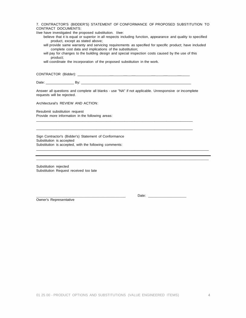
01 25 00 - PRODUCT OPTIONS AND SUBSTITUTIONS (VALUE ENGINEERED ITEMS) 4
7. CONTRACTOR'S (BIDDER'S) STATEMENT OF CONFORMANCE OF PROPOSED SUBSTITUTION TO CONTRACT DOCUMENTS: I/we have investigated the proposed substitution. I/we:
believe that it is equal or superior in all respects including function, appearance and quality to specified product, except as stated above;
will provide same warranty and servicing requirements as specified for specific product; have included complete cost data and implications of the substitution;
will pay for changes to the building design and special inspection costs caused by the use of this product;
will coordinate the incorporation of the proposed substitution in the work.
CONTRACTOR (Bidder): ________________ _____ __ ________ ____ _____ ____
Date: By:
Answer all questions and complete all blanks - use "NA" if not applicable. Unresponsive or incomplete requests will be rejected.
Architectural's REVIEW AND ACTION:
Resubmit substitution request Provide more information in the following areas: ______________________________________________________________________________
______________________________________________________________________________
Sign Contractor's (Bidder's) Statement of Conformance Substitution is accepted Substitution is accepted, with the following comments: ______________________________________________________________________________________
______________________________________________________________________________________
Substitution rejected Substitution Request received too late
_____________________________________________ Date: ___________________ Owner's Representative
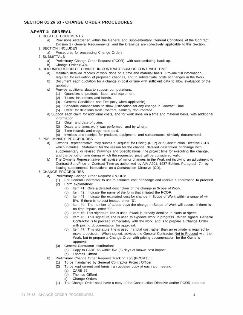
01 26 63 - CHANGE ORDER PROCEDURES 1
SECTION 01 26 63 - CHANGE ORDER PROCEDURES
A.PART 1: GENERAL 1. RELATED DOCUMENTS
a) Provisions established within the General and Supplementary General Conditions of the Contract, Division 1 - General Requirements, and the Drawings are collectively applicable to this Section.
2. SECTION INCLUDES a) Procedures for processing Change Orders.
3. SUBMITTALS a) Preliminary Change Order Request (PCOR) with substantiating back-up. b) Change Order (CO).
4. DOCUMENTATION OF CHANGE IN CONTRACT SUM OR CONTRACT TIME a) Maintain detailed records of work done on a time and material basis. Provide full information
required for evaluation of proposed changes, and to substantiate costs of changes in the Work. b) Document each quotation for a change in cost or time with sufficient data to allow evaluation of the
quotation. c) Provide additional data to support computations.
(1) Quantities of products, labor, and equipment. (2) Taxes, insurances and bonds. (3) General Conditions and Fee (only when applicable). (4) Schedule comparisons to show justification for any change in Contract Time. (5) Credit for deletions from Contract, similarly documented.
d) Support each claim for additional costs, and for work done on a time and material basis, with additional information. (1) Origin and date of claim. (2) Dates and times work was performed, and by whom. (3) Time records and wage rates paid. (4) Invoices and receipts for products, equipment, and subcontracts, similarly documented.
5. PRELIMINARY PROCEDURES a) Owner's Representative may submit a Request for Pricing (RFP) or a Construction Directive (CD)
which includes: Statement for the reason for the change, detailed description of change with supplementary or revised Drawings and Specifications, the project time for executing the change, and the period of time during which the requested price will be considered valid.
b) The Owner's Representative will advise of minor changes in the Work not involving an adjustment to Contract Sum/Price or Contract Time as authorized by AIA A201, 1987 Edition, Paragraph 7.4 by issuing supplemental instructions on a Construction Directive (CD).
6. CHANGE PROCEDURES a) Preliminary Change Order Request (PCOR):
(1) For General Contractor to use to estimate cost of change and receive authorization to proceed. (2) Form explanation:
(a) Item #1: Give a detailed description of the change in Scope of Work. (b) Item #2: Indicate the name of the form that initiated the PCOR. (c) Item #3: Indicate the extimated cost for change in Scope of Work within a range of +/-
5%. If there is no cost impact, enter "0". (d) Item #4: The number of added days the change in Scope of Work will cause. If there is
no time impact, enter "0". (e) Item #5: This signature line is used if work is already detailed in plans or specs. (f) Item #6: This signature line is used to expedite work in progress. When signed, General
Contractor is to proceed immediately with the work, and is to prepare a Change Order with pricing documentation for approval.
(g) Item #7: This signature line is used if a total cost rather than an estimate is required to make a decision. When signed, advises the General Contractor Not to Proceed with the Work, but to prepare a Change Order with pricing documentation for the Owner's approval.
(3) General Contractor distribution: (a) Copy to CARE 66 within five (5) days of known cost impact. (b) Thomas Gifford
b) Preliminary Change Order Request Tracking Log (PCORTL): (1) To be maintained by General Contractor Project Officer. (2) To be kept current and furnish an updated copy at each job meeting:
(a) CARE 66 (b) Thomas Gifford c) Change Orders
(1) The Change Order shall have a copy of the Construction Directive and/or PCOR attached,

01 26 63 - CHANGE ORDER PROCEDURES 2
along with all backup necessary to substantiate the requested change. (2) The Change Order will be directed to CARE 66 for signature.
d) Change Order Tracking Log (COTL): (1) To be maintained by General Contractor Project Manager. (2) Copy monthly or more often, if necessary:
(a) CARE 66 (b) Calott and Gifford
7. CORRELATION OF CONTRACTOR SUBMITTALS a) Promptly revise Schedule of Values and Application for Payment forms to record each authorized
Change Order, adjust the Contract Sum as shown on Change Order. b) Promptly revise Progress Schedules to reflect any change in Contract Time, revise subschedules to
adjust times for other items of work affected by the change, and resubmit. c) Promptly enter changes in Project Record Documents.
B.PART 2: PRODUCTS
a) Not applicable to this Section.
C.PART 3: EXECUTION a) Not applicable to this Section.
D.PART 4: FORMS
a) Not applicable to this Section. END OF SECTION 01 26 63 - CHANGE ORDER PROCEDURES
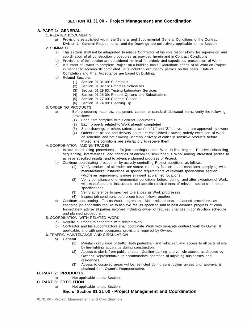
SECTION 01 31 00 - Project Management and Coordination
A. PART 1: GENERAL 1. RELATED DOCUMENTS
a) Provisions established within the General and Supplemental General Conditions of the Contract, Division 1 - General Requirements, and the Drawings are collectively applicable to this Section.
2. SUMMARY a) This section shall not be interpreted to relieve Contractor of his sole responsibility for supervision and
coordination of all construction procedures as provided herein and in Contract Conditions. b) Provisions of this section are considered minimal for orderly and expeditious prosecution of Work. c) It is intent of Owner to complete Project on a building basis. Coordinate efforts of all Work on Project
in manner to accomplish completed units including occupancy permits on this basis. Date of Completion and Final Acceptance are based by building.
d) Related Sections (1) Section 01 31 00: Submittals (2) Section 01 32 16: Progress Schedules (3) Section 01 29 83: Testing Laboratory Services (4) Section 01 25 00: Product Options and Substitutions (5) Section 01 77 00: Contract Closeout (6) Section 01 74 00: Cleaning Up
3. ORDERING PRODUCTS a) Before ordering materials, equipment, custom or standard fabricated items, verify the following
provisions: (1) Each item complies with Contract Documents (2) Each properly related to Work already completed (3) Shop drawings or others submittal confirm "1." and "2." above, and are approved by owner (4) Orders are placed and delivery dates are established allowing orderly execution of Work
on schedule and not allowing untimely delivery of critically sensitive products before Project site conditions are satisfactory to receive them.
4. COORDINATION AMONG TRADES a) Initiate coordinating procedures at Project meetings before Work in field begins. Resolve scheduling,
sequencing, interferences, and priorities of oncoming simultaneous Work among interested parties to achieve specified results, and to advance planned progress of Project.
b) Continue coordinating procedures by actively controlling Project conditions as follows: (1) Verify products of all trades are stored in orderly fashion under conditions complying with
manufacturer's instructions or specific requirements of relevant specification section whichever requirement is more stringent at planned locations.
(2) Verify compliance of environmental conditions before, during, and after execution of Work, with manufacturer's instructions and specific requirements of relevant sections of these specifications.
(3) Verify adherence to specified tolerances as Work progresses. (4) Inspect job conditions before one trade follows another.
c) Continue coordinating effort as Work progresses. Make adjustments in planned procedures as changing job conditions require to achieve results specified and to best advance progress of Work. Immediately advise all parties involved including owner of required changes in construction schedule and planned procedure.
5. COORDINATION WITH RELATED WORK a) Require all trades to cooperate with related Work. b) Contractor and his subcontractors shall coordinate Work with separate contract work by Owner, if
applicable, and with prior occupancy provisions required by Owner. 6. TRAFFIC MAINTENANCE AND CIRCULATION
a) General (1) Maintain circulation of traffic, both pedestrian and vehicular, and access to all parts of site
by fire-fighting apparatus during construction. (2) Access to site is from public streets. Confine parking and vehicle access as directed by
Owner's Representative to accommodate operation of adjoining businesses and residences.
(3) Access to occupied areas will be restricted during construction unless prior approval is obtained from Owner's Representative.
B. PART 2: PRODUCTS a) Not applicable to this Section.
C. PART 3: EXECUTION a) Not applicable to this Section.
End of Section 01 31 00 - Project Management and Coordination
01 31 00 - Project Management and Coordination
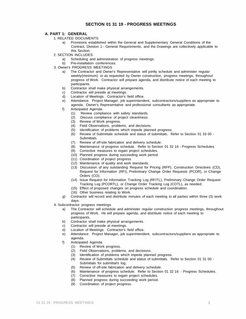
01 31 19 - PROGRESS MEETINGS 1
SECTION 01 31 19 - PROGRESS MEETINGS
A. PART 1: GENERAL 1. RELATED DOCUMENTS
a) Provisions established within the General and Supplementary General Conditions of the Contract, Division 1 - General Requirements, and the Drawings are collectively applicable to this Section.
2. SECTION INCLUDES a) Scheduling and administration of progress meetings. b) Pre-installation conferences.
3. Owner's PROGRESS MEETINGS a) The Contractor and Owner's Representative will jointly schedule and administer regular
weekly(minimum) or as requested by Owner construction, progress meetings, throughout progress of Work. Contractor will prepare agenda, and distribute notice of each meeting to participants.
b) Contractor shall make physical arrangements. c) Contractor will preside at meetings. d) Location of Meetings: Contractor's field office. e) Attendance: Project Manager, job superintendent, subcontractors/suppliers as appropriate to
agenda. Owner's Representative and professional consultants as appropriate. f) Anticipated Agenda.
(1) Review compliance with safety standards. (2) Discuss compliance of project cleanliness. (3) Review of Work progress. (4) Field Observations, problems, and decisions. (5) Identification of problems which impede planned progress. (6) Review of Submittals schedule and status of submittals. Refer to Section 01 33 00 -
Submittals. (7) Review of off-site fabrication and delivery schedule. (8) Maintenance of progress schedule. Refer to Section 01 32 16 - Progress Schedules. (9) Corrective measures to regain project schedules. (10) Planned progress during succeeding work period. (11) Coordination of project progress. (12) Maintenance of quality and work standards. (13) Discussion of any outstanding Request for Pricing (RFP), Construction Directives (CD),
Request for Information (RFI), Preliminary Change Order Requests (PCOR), or Change Orders (CO).
(14) Issue Request for Information Tracking Log (RFITL), Preliminary Change Order Request Tracking Log (PCORTL), or Change Order Tracking Log (COTL), as needed.
(15) Effect of proposed changes on progress schedule and coordination. (16) Other business relating to Work.
g) Contractor will record and distribute minutes of each meeting to all parties within three (3) work days.
4. Subcontractor progress meetings a) The Contractor will schedule and administer regular construction progress meetings, throughout
progress of Work. He will prepare agenda, and distribute notice of each meeting to participants.
b) Contractor shall make physical arrangements. c) Contractor will preside at meetings. d) Location of Meetings: Contractor's field office. e) Attendance: Project Manager, job superintendent, subcontractors/suppliers as appropriate to
agenda. f) Anticipated Agenda.
(1) Review of Work progress. (2) Field Observations, problems, and decisions. (3) Identification of problems which impede planned progress. (4) Review of Submittals schedule and status of submittals. Refer to Section 01 31 00 -
Submittals for submittal's log. (5) Review of off-site fabrication and delivery schedule. (6) Maintenance of progress schedule. Refer to Section 01 32 16 - Progress Schedules. (7) Corrective measures to regain project schedules. (8) Planned progress during succeeding work period. (9) Coordination of project progress.
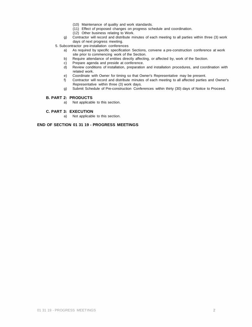
01 31 19 - PROGRESS MEETINGS 2
(10) Maintenance of quality and work standards. (11) Effect of proposed changes on progress schedule and coordination. (12) Other business relating to Work.
g) Contractor will record and distribute minutes of each meeting to all parties within three (3) work days of next progress meeting.
5. Subcontractor pre-installation conferences a) As required by specific specification Sections, convene a pre-construction conference at work
site prior to commencing work of the Section. b) Require attendance of entities directly affecting, or affected by, work of the Section. c) Prepare agenda and preside at conference. d) Review conditions of installation, preparation and installation procedures, and coordination with
related work. e) Coordinate with Owner for timing so that Owner's Representative may be present. f) Contractor will record and distribute minutes of each meeting to all affected parties and Owner's
Representative within three (3) work days. g) Submit Schedule of Pre-construction Conferences within thirty (30) days of Notice to Proceed.
B. PART 2: PRODUCTS
a) Not applicable to this section.
C. PART 3: EXECUTION a) Not applicable to this section.
END OF SECTION 01 31 19 - PROGRESS MEETINGS

SECTION 01 32 00 – CONSTRUCTION PROGRESS DOCUMENTATION
A. PART 1: GENERAL 1. RELATED DOCUMENTS
a) Provisions established within the General and Supplementary General Conditions of the Contract, Division 1 - General Requirements, and the Drawings are collectively applicable to this Section.
2. SECTION INCLUDES a) Procedures for preparation and submittal of construction Progress Schedules.
3. FORMAT a) Prepare schedule as approved by the Owner's Representative.
(1) An activity for each G703 line item. (2) Milestone for each rough and final inspection. (3) Milestone for temporary certificate of occupancy and certificate of occupancy. (4) Milestone for Owner's acceptance and turnover. (5) Activity for punchlist correction both for contractor's and Owner's punchlist.
4. CONTENT a) Show complete sequence of construction by activity, with dates for beginning and
completion of each element of construction. 5. REVISIONS TO SCHEDULES (Bi-MONTHLY)
a) Indicate progress of each activity to date of submittal, and projected completion date of each activity.
b) Identify activities modified since previous submittal, major changes in scope, and other identifiable changes.
c) Provide narrative report to define problem areas, anticipated delays, actual delays, and impact on Schedule. Report corrective action taken, or proposed, and its effect.
6. SUBMITTALS a) Submit initial Schedules with bidding documents. b) Submit revised Progress Schedules at each job meeting and with each Application for
Payment. c) Distribution: One (1) copy each to Owner's Representative, field office at project site,
and inspecting consultant. 7. DISTRIBUTION
a) Distribute copies of reviewed Schedules to job site file, subcontractors, suppliers, and other concerned entities.
b) Instruct recipients to promptly report, in writing, problems anticipated by projections in Schedules.
B. PART 2: PRODUCTS
a) Not applicable to this section.
C. PART 3: EXECUTION a) Not applicable to this section.
END OF SECTION 01 32 00 – CONSTRUCTION PROGRESS DOCUMENTATION
01 32 00 – CONSTRUCTION PROGRESS DOCUMENTATION
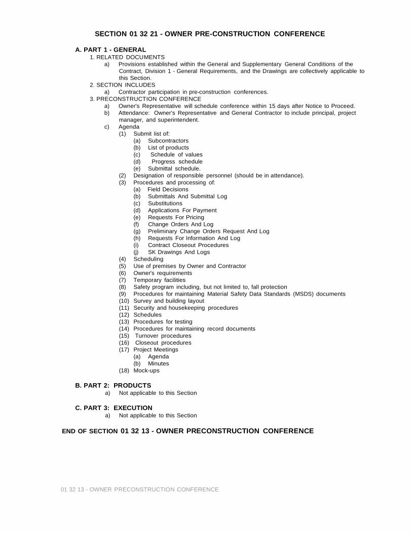
SECTION 01 32 21 - OWNER PRE-CONSTRUCTION CONFERENCE
A. PART 1 - GENERAL 1. RELATED DOCUMENTS
a) Provisions established within the General and Supplementary General Conditions of the Contract, Division 1 - General Requirements, and the Drawings are collectively applicable to this Section.
2. SECTION INCLUDES a) Contractor participation in pre-construction conferences.
3. PRECONSTRUCTION CONFERENCE a) Owner's Representative will schedule conference within 15 days after Notice to Proceed. b) Attendance: Owner's Representative and General Contractor to include principal, project
manager, and superintendent. c) Agenda
(1) Submit list of: (a) Subcontractors (b) List of products (c) Schedule of values (d) Progress schedule (e) Submittal schedule.
(2) Designation of responsible personnel (should be in attendance). (3) Procedures and processing of:
(a) Field Decisions (b) Submittals And Submittal Log (c) Substitutions (d) Applications For Payment (e) Requests For Pricing (f) Change Orders And Log (g) Preliminary Change Orders Request And Log (h) Requests For Information And Log (i) Contract Closeout Procedures (j) SK Drawings And Logs
(4) Scheduling (5) Use of premises by Owner and Contractor (6) Owner's requirements (7) Temporary facilities (8) Safety program including, but not limited to, fall protection (9) Procedures for maintaining Material Safety Data Standards (MSDS) documents (10) Survey and building layout (11) Security and housekeeping procedures (12) Schedules (13) Procedures for testing (14) Procedures for maintaining record documents (15) Turnover procedures (16) Closeout procedures (17) Project Meetings
(a) Agenda (b) Minutes
(18) Mock-ups
B. PART 2: PRODUCTS a) Not applicable to this Section
C. PART 3: EXECUTION
a) Not applicable to this Section
END OF SECTION 01 32 13 - OWNER PRECONSTRUCTION CONFERENCE
01 32 13 - OWNER PRECONSTRUCTION CONFERENCE

01 33 00 – SUBMITTALS 1
SECTION 01 33 00 - SUBMITTALS
A. PART 1: GENERAL 1. RELATED DOCUMENTS
a) Provisions established within the General and Supplementary General Conditions of the Contract, Division 1 - General Requirements, and the Drawings are collectively applicable to this Section.
b) Reference Section 01 25 00 - Product Options and Substitutions, for substitutions and National Purchase Agreements.
2. SUMMARY a) General Provisions
(1) Provisions in this section are mandatory procedures for preparing and submitting samples, shop drawings, and product data.
(2) Job delays occasioned by requirement of resubmission of samples, shop drawings, and product data not in accord with Contract Documents are Contractor's responsibility, and will not be considered valid justification for extension of time.
b) Submittal Log: (1) Contractor to complete attached submittals log and submit proposed submittal
schedule to Owner's Representative for review within fifteen calendar days following Notice to Proceed.
(2) Schedule purpose is to: (a) Demonstrate that submittals, shop drawings, data, samples and mock-ups
required for Work are addressed by Contractor. (b) Demonstrate consistency with Contractor's proposed Progress Schedule. (c) Assist Owner's Representative in scheduling timely review/approval action of
submittals. (3) Schedule contents: Description of submitted item, proposed date of submittal or
availability for review by Owner's Representative and proposed date of requested return by Owner's Representative, allowing twenty work days for Owner Processing.
(4) Within fifteen calendar days after Owner's Representative receipt of submittal schedule, Owner's Representative and Contractor shall jointly review schedule and mutually agree to acceptability or necessary modifications.
(5) Submit accepted schedule within ten calendar days after joint review date.
3. MOCK-UPS - ALL SYSTEMS a) Furnish and install "Z" shaped mock-up depicting building inside and outside corner which
includes but is not limited to the following systems: (1) Framing. (2) Sheathing. (3) Stucco and accessories. (4) Roofing. (5) Painting. (6) Window / door frames.
b) Mock-ups to remain on-site until final project completion. c) Accepted mock-ups to represent standard of quality for the project. d) Mock-ups to be approved by Owner's Representative prior to commencement of building
construction. 4. SAMPLE PREPARATION
a) Prepare samples in sizes, shapes, and finishes in accord with provisions of individual specification sections.
b) Samples furnished under this section are not to be confused with full size, on-the-site "Mock-Ups" called for in some specification sections.
c) Number of samples submitted: Three (3): Two (2) required by Contractors, plus one (1) which will be retained by Owner, unless otherwise indicated.
d) Samples Requiring Color Selection (1) Submit at earliest practical time. (2) No color selections will be made until all colors can be chosen and issued at one
time in form of color schedule. (3) Approvals and color selections will not be made unilaterally where samples or
selections regarding adjacent materials must be made for aesthetic purposes. 5. SHOP DRAWING PREPARATION
a) Conform to the Following Requirements (1) Number sheets consecutively. (2) Indicate working and erection dimensions and relationships to adjacent work.

01 33 00 – SUBMITTALS 2
Concurrent submittals of different aspects of work may be required by Owner's Representative as deemed necessary to demonstrate Contractor's ability to understand these relationships and coordinate Work.
(3) Indicate: (a) Arrangements and section views, as applicable. (b) Material, gauges, thicknesses, finishes, and characteristics. (c) Anchoring and fastening details: include information for making connections to
adjacent work. (4) Provide 3" by 3" clean space in the lower right hand area for entry of the Contractor's
and the Architecturals stamp. (5) Cross-reference drawing details and specification paragraphs applicable to
submitted data. b) Submit blue line copies of shop drawings. Provide copies as follows:
(1) Number required by Contractor for coordination and execution of Work. (2) Two (2) copies for Owner, and Owner Representative's files.. (3) Copies retained by Architect as follows:
(a)Work designed by engineers or other consultants -- two copies. (b)All other work -- one copy.
6. PRODUCT DATA PREPARATION a) Include product manufacturer's standard printed material, dated, with product description
and installation instructions indicated: delete data not related to this Project or mark "VOID" as applicable.
b) Number of copies submitted: Number required by Contractor plus two which will be retained by Owner's Representative, and one (1) copy per reviewing architect/engineer consultant.
7. CONTRACTOR'S REVIEW a) Review submittals and stamp with approval action stamp containing Contractor's name,
work "Approved", signed initials of approving agent, date of approval action, review notes, comments, and corrections required prior to submission to Owner's Representative. By so noting, Contractor indicates that he has reviewed and approved materials, equipment, quantities, and field verified dimensions represented by particular submittal.
b) Contractor represents by submitting samples, shop drawings, and product data that he has complied with provisions specified above. Submissions made without Contractor's approval indicated thereon will be returned without being reviewed for compliance with this requirement.
c) Date each submittal indicating name of Project, Architect, Engineer, Contractor, Subcontractor, as applicable description or name of equipment, material, or product and identify Work use location.
d) Accompany submittal with transmittal letter containing project name, Contractor's name, number of samples or drawings, titles, and other pertinent data. Outline deviations, if any, in submittals from requirements of Contract Documents.
8. ARCHITECT'S REVIEW a) Review submittal with reasonable promptness to cause no delay in Work. b) Review is only for conformance with design concept of project and information in Contract
Documents. Review of separate item shall not indicate approval of an assembly in which item functions.
c) Architect will return submittals to Owner's Representative for distribution. 9. RESUBMISSION
a) Make corrections and changes indicated for unapproved submissions -- resubmit in same manner as specified above until Architect's or Owner's approval is obtained.
b) Direct specific attention to revisions other than corrections requested by Architect on previous submissions, if any, in resubmission transmittal.
10. DISTRIBUTION a) Contractor is responsible for obtaining and distributing copies of submittal to his
Subcontractors and material suppliers. b) Maintain orderly file of all approved submittals bearing Architect's, Engineer's, or Owner's
stamp for Project duration -- deliver to Owner's Representative as part of Project closeout documents.
End of Section 01 33 00 - SUBMITTALS

SECTION 01 40 00 - QUALITY REQUIREMENTS
A. PART 1: GENERAL 1. RELATED DOCUMENTS
a) Provisions established within the General and Supplementary General Conditions of the Contract, Division 1 - General Requirements, and the Drawings are collectively applicable to this Section.
2. SECTION INCLUDES a) Quality control of products and workmanship. b) Manufacturer's instructions, certificates and field services. c) Mockups and Field Samples.
3. DESCRIPTION a) Maintain quality control over supervision, subcontractors, suppliers, manufacturers,
products, services workmanship, and site conditions, to produce Work in accordance with Contract Documents.
4. WORKMANSHIP a) Comply with industry standards of the region except when more restrictive tolerances or
specified requirements indicate more rigid standards or more precise workmanship. b) Provide suitably qualified personnel to produce Work of specified quality. c) Secure products in place with positive anchorage devices designed and sized to withstand
stresses, vibration, and racking. d) Provide finishes to match approved samples.
5. MANUFACTURER'S INSTRUCTIONS AND CERTIFICATES a) Require compliance with instructions in full detail, including each step in sequence. b) Should instruction conflict with Contract Documents, request clarification from Owner's
Representative before proceeding. c) When required in individual Specifications section, submit manufacturer's certificate, in
duplicate, certifying that products meet or exceed specified requirements, executed by responsible officer.
6. MANUFACTURER'S FIELD SERVICES a) When required by manufacturer for warranty validation, have manufacturer or his
authorized representative provide qualified representative to observe field conditions, conditions of surfaces and installation, quality of workmanship, start-up of equipment test, adjust, and balance of equipment as applicable, and to make written report of observations and recommendations to Owner's Representative.
b) Individuals to report observations and site decisions or instructions given to applicators or installers that are supplemental or contrary to manufacturer's written instructions.
c) Submit report in duplicate within three (3) days of observation to Owner's Representative for review.
7. MOCKUPS / FIELD SAMPLES a) Assemble and erect mock-ups and field samples complete with specified attachment and
anchorage devices, flashings, seals, and finishes. b) Acceptable mockups and field samples may be retained in completed Work. c) Install mock-ups and field samples at the site required by individual specifications Sections
for review, or as directed by Owner's Representative. d) Acceptable samples represent a quality level for the Work.
B. PART 2: PRODUCTS
a) Not applicable to this section.
C. PART 3: EXECUTION a) Not applicable to this section.
END OF SECTION 01 40 00 - QUALITY REQUIREMENTS
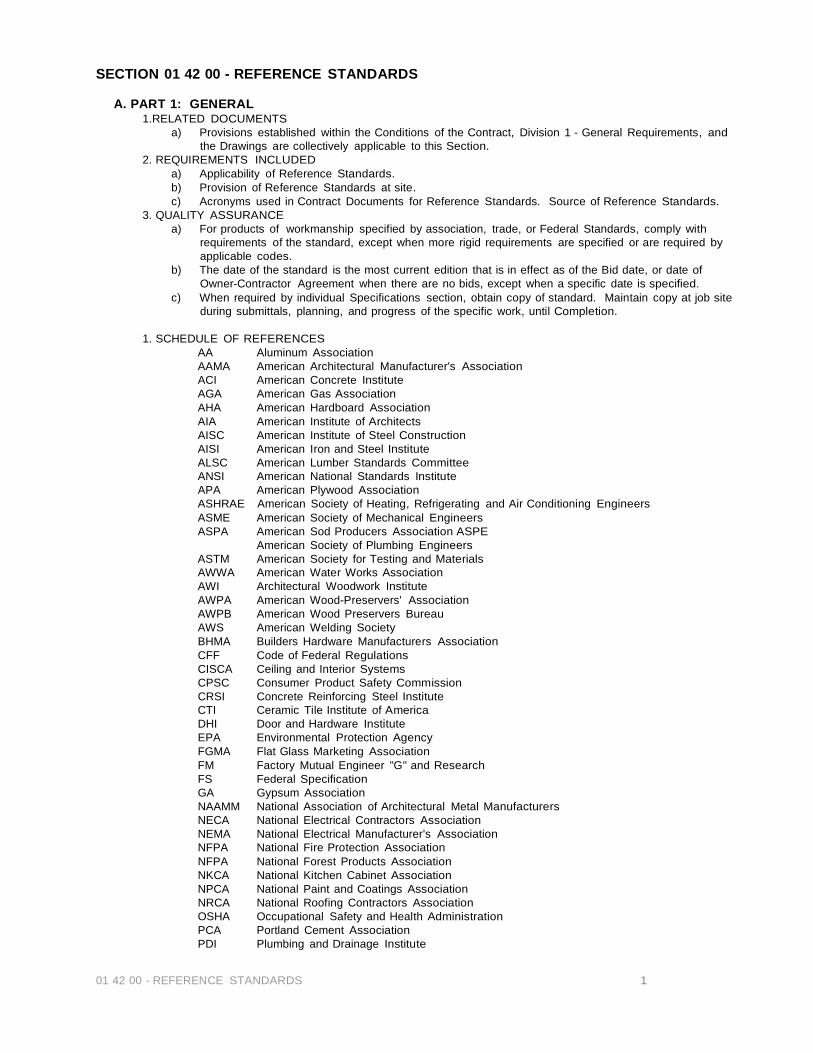
01 42 00 - REFERENCE STANDARDS 1
SECTION 01 42 00 - REFERENCE STANDARDS
A. PART 1: GENERAL 1.RELATED DOCUMENTS
a) Provisions established within the Conditions of the Contract, Division 1 - General Requirements, and the Drawings are collectively applicable to this Section.
2. REQUIREMENTS INCLUDED a) Applicability of Reference Standards. b) Provision of Reference Standards at site. c) Acronyms used in Contract Documents for Reference Standards. Source of Reference Standards.
3. QUALITY ASSURANCE a) For products of workmanship specified by association, trade, or Federal Standards, comply with
requirements of the standard, except when more rigid requirements are specified or are required by applicable codes.
b) The date of the standard is the most current edition that is in effect as of the Bid date, or date of Owner-Contractor Agreement when there are no bids, except when a specific date is specified.
c) When required by individual Specifications section, obtain copy of standard. Maintain copy at job site during submittals, planning, and progress of the specific work, until Completion.
1. SCHEDULE OF REFERENCES
AA Aluminum Association AAMA American Architectural Manufacturer's Association ACI American Concrete Institute AGA American Gas Association AHA American Hardboard Association AIA American Institute of Architects AISC American Institute of Steel Construction AISI American Iron and Steel Institute ALSC American Lumber Standards Committee ANSI American National Standards Institute APA American Plywood Association ASHRAE American Society of Heating, Refrigerating and Air Conditioning Engineers ASME American Society of Mechanical Engineers ASPA American Sod Producers Association ASPE American Society of Plumbing Engineers ASTM American Society for Testing and Materials AWWA American Water Works Association AWI Architectural Woodwork Institute AWPA American Wood-Preservers' Association AWPB American Wood Preservers Bureau AWS American Welding Society BHMA Builders Hardware Manufacturers Association CFF Code of Federal Regulations CISCA Ceiling and Interior Systems CPSC Consumer Product Safety Commission CRSI Concrete Reinforcing Steel Institute CTI Ceramic Tile Institute of America DHI Door and Hardware Institute EPA Environmental Protection Agency FGMA Flat Glass Marketing Association FM Factory Mutual Engineer "G" and Research FS Federal Specification GA Gypsum Association NAAMM National Association of Architectural Metal Manufacturers NECA National Electrical Contractors Association NEMA National Electrical Manufacturer's Association NFPA National Fire Protection Association NFPA National Forest Products Association NKCA National Kitchen Cabinet Association NPCA National Paint and Coatings Association NRCA National Roofing Contractors Association OSHA Occupational Safety and Health Administration PCA Portland Cement Association PDI Plumbing and Drainage Institute

01 42 00 - REFERENCE STANDARDS 2
PS Product Standard PTI Post Tension Institute SDI Steel Door Institute SIGMA Sealed Insulating Glass Manufacturers Association SMACNA Sheet Metal and Air Conditioning Contractors National Association SPIB Southern Pine Inspection Bureau SSPC Steel Structures Painting Council TCA Tile Council of America, Inc. UL Underwriter's Laboratories, Inc. UPC Uniform Plumbing Code WCLIB West Coast Lumber Inspection Bureau WWPA Western Wood Products Association
A. PART 2: PRODUCTS
a) Not applicable to this Section.
B. PART 3: EXECUTION a) Not applicable to this Section.
END OF SECTION 01 42 00 - REFERENCE STANDARDS

01 45 23 - TESTING & INSPECTING SERVICES 1
SECTION 01 45 23 - TESTING & INSPECTING SERVICES
A. PART 1: GENERAL 1. SUMMARY
a) Related Documents b) Provisions established within the General and Supplementary General Conditions of the Contract,
Division I - General Requirements, and the Drawings collectively applicable to this Section. 2. SECTION INCLUDES
a) Owner provided testing laboratory services. b) Selection and payment. c) Laboratory responsibilities. d) Laboratory reports. e) Limits on testing laboratory authority. f) Contractor responsibilities. g) Schedule of inspections and tests.
3. SELECTION AND PAYMENT a) Contractor will employ services of an independent testing laboratory to perform specified
inspection and testing. Contractor will be paid by Owner. b) Employment of testing laboratory shall in no way relieve Contractor of obligation to perform Work
in accordance with requirements of Contract Documents. Contractor will pay all testing required by local authorities having jurisdiction.
4. LABORATORY RESPONSIBILITIES a) Test samples of mixes submitted by Contractor. b) Provide qualified personnel at site. Cooperate with Contractor and Inspecting A/E in the
performance of services. c) Perform specified inspection, sampling and testing of products in accordance with specified
standards. d) Ascertain compliance of materials and mixes with requirements of Contract Documents. e) Promptly notify Owner's Representative of observed irregularities or non-conformance of Work or
product. f) Perform additional inspections and tests required by Owner's Representative.
5. LABORATORY REPORTS a) After each inspection and test, promptly submit one copy of laboratory report to Architect, Owner's
Representative, applicable consultants, and to Contractor. Include: Date issued, Project title and number, name of inspector, date and time of sampling or inspection, identification of product and Specifications section, location in the Project, type of inspection or test, date of test, results of tests, and conformance with Contract Documents. When requested by Inspecting A/E, Engineer, Contractor, or Owner provide interpretation of test results.
b) Make written recommendations of procedures to correct unforeseen conditions not addressed in soils reports. (1) Such recommendations must be approved in writing by Owner's Representative prior to implementation.
6. LIMITS ON TESTING LABORATORY AUTHORITY a) Laboratory may not release, revoke, alter, or enlarge on requirements of Contract Documents. b) Laboratory may not approve or accept any portion of the Work, unless approved by Owner's
Representative. c) Laboratory may not assume any duties of Contractor. d) Laboratory has no authority to stop Work, unless otherwise approved by Owner's Representative.
7. CONTRACTOR RESPONSIBILITIES a) Provide adequate samples of materials proposed to be used which require testing, together with
proposed mix designs. b) Cooperate with laboratory personnel, and provide access to Work and to manufacturer's facilities. c) Provide incidental labor and facilities to provide access to work to be tested, to obtain and handle
samples at the site or at source of products to be tested, to facilitate tests and inspections, and for storage and curing of test samples.
d) Notify laboratory of materials sources and furnish necessary quantities of representative samples of materials proposed for use which are required to be tested.
e) Notify Owner's Representative and laboratory 24 hours prior to expected time for operations requiring inspection and testing services.
f) Advise laboratory in a timely fashion to complete required inspection and testing prior to subsequent work being performed.
g) Pay for all subsequent testing of products or systems found to be defective or otherwise not in accordance with specification requirements. Remove rejected products and replace with products of specified quality.
B. PART 2: PRODUCTS
A) Not applicable to this section.
01 45 23 - TESTING & INSPECTING SERVICES 2
C. PART 3: EXECUTION 1. EARTHWORK (SITE GENERAL)
a) Make necessary soil tests (Atterberg Limit Series and ASTM D698 Standard Proctor) to determine moisture content and density of existing subgrade. Perform necessary soil tests (Atterberg Limit Series and ASTM D698 Standard Proctor for each type of fill specified) to determine the moisture content of existing subgrade and to inspect and test the placement of additional fill lifts to verify that all fill materials used are in accordance with the specifications for that use. Perform one field density test (ASTM D2922) per 10,000 S.F. of site area in the area affected on each lift prior to placement of additional fill material.
2. TRENCHING a) Make necessary soil compaction tests in all trenching.
3. PAVING SUBGRADE STABILIZATION a) Perform one subgrade in-place density test per 7,500 S.F. of subgrade, after subgrade preparation is complete at locations determined by the soils engineer, in accordance with ASTM D2922 and ASTM D3017. Perform tests within 48 hours of placement of pavement construction.
4. BUILDING SUBGRADE STABILIZATION a) Make necessary soils tests (Atterberg Limit Series and ASTM D698 Standard Proctor for each type of fill specified) to determine the moisture content and density of existing subgrade and inspect and test the placement of additional fill lifts to verify that all fill materials used are in accordance with the specifications for that use. Perform one field density test (ASTM D2922) for each 5,000 S.F. of area within the building footprint on each lift prior to placement of additional fill material.
5. FORMWORK, REINFORCING STEEL AND INSERTS a) Prior to each concrete pour, inspect formwork for tightness of joints, proper shoring and bracing, and beam size in accordance with ACI 347. b) Prior to each concrete pour, inspect fabrication and bending of bars, bar sizes, spacing, placement and tying to accordance with ACI 315. c) Prior to each concrete pour, inspect positioning of steel inserts, assemblies, sizes and spacing.
6. CAST-IN-PLACE CONCRETE a) Design Mixes
(1) All concrete mixtures to be reviewed by the Design Engineer and/or the testing laboratory. (2) At the beginning of the work Contractor shall submit proposed concrete mixes, including test results, for review by the Owner's Representative and testing laboratory, including the sieve analysis of fine and course aggregate ASTM C-136, dry rodded weight of coarse aggregate - ASTM C-29, and the specific gravity (bulk saturated surface dry), of fine and coarse aggregates ASTM C127 and C128. Laboratory, Architectural, Contractor, and Owner's Representative will review and make mix modification recommendations. (3) Do not mix concrete for placing in the work until after laboratory reports reflect that each
proposed mix will develop the strength required. b) Test Cylinders: Make at least one (1) test of each day's pouring of each one hundred (100) cu. yards, whichever comes first, for each type of concrete (1 per building. minimum for foundations; 1 per building. minimum for pea gravel hardrock), on each different portion or section of the work. Mold and cure specimens in accordance with ASTM C31, and test in accordance with ASTM C39. Test cylinders shall be made and tested by the laboratory in accordance with ASTM C 172. Footings, walls, and floor systems constitute different sections. Each test shall consist of four (4) specimens, one (1) of which shall be broken at seven (7) days, two (2) at twenty-eight (28) days and one held in reserve. Determine temperature and air content for each set of test cylinders in accordance with ASTM C231. c) Field Quality Control
(1)Determine slump for each strength test and whenever consistency of concrete appears to vary, in accordance with ASTM C143. (2) Monitor addition of water to concrete and length of time concrete is allowed to remain in truck. (3) Notate and verify delivery tickets indicating class of concrete, time test was performed, truck ticket number, amount of water added during initial batching, time initial batching occurred, and location of each placement. (4) Monitor work being performed in accordance with ACI (American Concrete Institute) recommendations as a standard of quality. (5) Notify job superintendent of any non-conformance immediately and note on daily job report including how resolved.
END OF SECTION 01 45 23 - TESTING & INSPECTING SERVICES
01 50 00 - TEMPORARY FACILITIES AND CONTROLS 1
SECTION 01 50 00 - TEMPORARY FACILITIES AND CONTROLS
A. PART 1: GENERAL 1. RELATED DOCUMENTS
a) Provisions established within the General and Supplementary General Conditions of the Contract, Division 1 - General Requirements, and the Drawings are collectively applicable to this Section.
2.SECTION INCLUDES a) Electricity, Lighting. b) Heat, Ventilation. c) Telephone Service. d) Water. e) Sanitary Facilities. f) Fire Protection. g) Barriers. h) Enclosures. i) Protection of Installed Work. j) Security. k) Water Control. l) Cleaning During Construction. m) Project Identification. n) Field Offices and Sheds. o) Access Roads and Temporary Parking. p) Scaffolding. q) Sedimentation and erosion control.
3. TEMPORARY ELECTRICITY a) Provide and pay for power service required from Utility source. b) Provide power outlets for construction operations. Provide adequate distribution equipment,
wiring, and outlets to provide single phase branch circuits for power and lighting, and as required by authorities having jurisdiction, and in accordance with all grounding requirements.
4. TEMPORARY LIGHTING a) Provide and maintain appropriate incandescent lighting for construction operations and as
required by authorities having jurisdiction. b) Provide branch wiring from power source to distribution boxes with lighting conductors, pigtails
and lamps as required. c) Maintain lighting and provide routine repairs. d) Permanent building lighting may be utilized during construction.
5. TEMPORARY HEAT a) Provide and pay for heat devices and heat as required to maintain specified conditions for
construction operations. b) Use of permanent heating/cooling systems for temporary heating/cooling shall not affect the
warranty period. c) Prior to operation of permanent equipment for temporary heating purposes, verify that
installation is approved for operation, equipment is lubricated and filters are in place. Provide and pay for operation, maintenance, and regular replacement of filters and worn or consumed parts.
d) Maintain appropriate ambient temperature in areas where construction is in progress, unless indicated otherwise in specifications.
e) Fuel oil heaters of any kind are not permitted. 6. TEMPORARY VENTILATION
a) Ventilate enclosed areas to assure cure of materials, to dissipate humidity, and to prevent accumulation of dust, fumes, vapors, or gases.
7. TEMPORARY TELEPHONE SERVICE a) Provide adequate, separate telephone service lines to field office for voice and data.
8. TEMPORARY WATER SERVICE a) Provide service required for construction operations. Extend branch piping with outlets located
so that water is available by use of hoses. b) All water shall be potable unless clearly marked otherwise.
9. TEMPORARY SANITARY FACILITIES a) Provide and maintain required facilities and enclosures.
(1) Use of permanent new facilities by construction personnel is prohibited. 10. TEMPORARY FIRE PROTECTION
a) Observe and enforce throughout the Work all requirements of City, State and Insurance authorities to minimize fire hazards.
b) Remove combustible refuse from within each building daily. c) Provide fire extinguishers as required by the local fire department, city ordinances, and OSHA.

01 50 00 - TEMPORARY FACILITIES AND CONTROLS 2
11. BARRIERS a) Provide as required to prevent public entry to construction areas and to protect existing facilities
and adjacent properties from damage from construction operations. b) Provide 6-foot high chain link fence around construction site and temporary construction staging
area; equip with vehicular and pedestrian gates with locks on outside. Do not damage existing asphalt or paving. Contractor must confirm extent of fencing with Owner's Representative prior to mobilization
c) Provide barricades and covered walkways as required by governing authorities for public rights- of-way and for public access to existing buildings.
12. ENCLOSURES a) Provide temporary weather-tight closures of openings in exterior surfaces to provide acceptable
working conditions and protection for materials, to allow for temporary heating, and to prevent entry of unauthorized persons. Provide doors with self-closing hardware and locks.
13. PROTECTION OF INSTALLED WORK a) Provide temporary protection for installed products. Control traffic in immediate area to
minimize damage. b) Provide protective coverings at walls, projections, jambs, sills, and soffits of openings. Protect
finished floors and stairs from traffic, movement of heavy objects, and storage. c) Prohibit traffic & storage on waterproofed & roofed surfaces, on lawn and landscaped areas.
14. PARKING a) All parking shall be at temporary construction staging area.
15. WATER CONTROL a) Grade site to drain. Maintain excavations free of water. Provide and operate pumping
equipment. b) Protect site from puddling or running water.
16. CLEANING DURING CONSTRUCTION a) Refer to Section 01 74 00 - Cleaning Up.
17. PROJECT IDENTIFICATION a) Provide only as required by authorities having jurisdiction.
18. FIELD OFFICES AND SHEDS a) Office: Weather-tight, with lighting, electrical outlets, telephone, heating, and air conditioning
equipment, and equipped with minimum of one layout table, one desk, file cabinet, plan rack, conference table and chairs sufficient for progress meetings.
b) Storage Container for Tools, Materials, and Equipment: Weather-tight, with heat and ventilation for Products requiring controlled conditions, with adequate space for organized storage and access, and lighting for inspection of stored materials.
19. SCAFFOLDING a) Type: Designed and installed by each contractor or subcontractor for his own use for work
during construction. Conform to special requirements of respective trades that use scaffolding and applicable rules and regulations of local building codes and governing agencies, including OSHA's fall protection program.
b) Erect scaffolding independent of building walls: Arrange to avoid interference with other trades as much as possible.
c) Remove scaffolding when no longer required. 20. SEDIMENTATION AND EROSION CONTROL
a) Provide adequate silt fencing and/or hay bails as erosion control material per design build SWWPP. Extent of fencing shall be as indicated on plans or as necessary to prevent onsite and offsite erosion and sedimentation.
21. REMOVAL OF UTILITIES, FACILITIES, AND CONTROLS a) Remove temporary materials, equipment, services, and construction prior to Completion
inspection. b) Clean and repair damage caused by installation or use of temporary facilities. Remove
underground installations to a depth of 2-feet; grade site as indicated. Restore existing facilities used during construction to specified, or to original, condition.
22. OSHA a) Workers shall wear protective clothing and other apparatus as appropriate to the work being
performed, as required by OSHA and other laws and ordinances. B. PART 2: PRODUCTS
a) Not applicable to this section. C. PART 3: EXECUTION
1. GENERAL a) Comply with applicable requirements specified in Division 15 - Mechanical and in Division 16 -
Electrical. b) Maintain and operate systems to assure continuous service. c) Modify and extend systems as work progress requires.
END OF SECTION 01500 - CONSTRUCTION FACILITIES AND TEMPORARY CONTROLS
SECTION 01 66 00 - PRODUCT STORAGE, AND HANDLING
A. PART 1: GENERAL 1. SUMMARY
a) Requirements of this section are general in nature. Refer to individual specification sections for additional, specific requirements.
b) Delivery (1) Deliver manufactured products to project site in manufacturer's original
packaging with labels and seals intact. Labels shall indicate manufacturer and product name, description, mixing and application instructions, and fire-resistive classifications as applicable.
(2) Inspect materials upon delivery to ensure proper material, color, type, quantity. (3) Deliver finish materials only after spaces are enclosed and adequate indoor
storage facilities are available. c) Storage
(1) Store materials and equipment under cover, off ground at least 4" and protect from excessive heat and freezing, except for materials not subject to damage or deterioration by contact with environmental conditions. Observe manufacturer's recommendations for positioning, separation and ventilation, as applicable.
(2) Prevent corrosion, soiling, breakage of materials, or contact with deleterious materials.
(3) Store and handle products subject to spillage in areas where spills will not deface finished surfaces or other Work or contaminate soil.
(4) Flammable or hazardous materials (a) Store minimum quantities in protected areas. (b) Provide appropriate type fire extinguisher near storage areas. (c) Observe manufacturer's precautions and applicable ordinances and
regulations. (5) Comply with each manufacturer's instructions and recommendations for products
storage and handling. (6) Provide material safety data sheet for all required materials in accordance with
governing regulations. d) Handling
(1) Handle materials and equipment to prevent damage, deterioration, or contamination.
(2) Installation of materials which are physically damaged or stained prior to time for installation is prohibited.
e) Inspection and Installation (1) Comply with manufacturer's product data in all aspects of basic material usage,
handling, installation and substrate preparation, except where more stringent requirements are specified in contract documents.
(2) Be responsible for verifying and obtaining proper substrate conditions, tolerances, and material alignments to receive applied or attached materials and construction.
(3) Provide substrates sound, clean, dry and free of imperfections or conditions which would be detrimental to reception of applied materials.
(4) Align material to give smooth, uniform surface planes within specified tolerances and straight, plumb surfaces.
(5) Inspect substrates prior to installation of applied materials. Correct unacceptable conditions prior to proceeding with Work.
(6) Provide finished surfaces clean, uniform, and free of damages, soiling, or defects in material and finish.
(7) Finished surfaces: Match color and texture of samples provided or approved by Owner's Representative.
(8) Protection (a) Protect finished surfaces from damage and soiling during application, drying
or curing, as applicable. (b) Provide temporary protective coverings or barriers as required.
END OF SECTION 01 66 00 - PRODUCT STORAGE, AND HANDLING
01 66 00 - PRODUCT STORAGE, AND HANDLING

01 70 00 - CONTRACT CLOSEOUT 1
SECTION 01 70 00 - CONTRACT CLOSEOUT
A. PART 1: GENERAL 1. RELATED DOCUMENTS
a) Provisions established within the General and Supplementary General Conditions of the Contract, Division 1 - General Requirements, and the Drawings are collectively applicable to this Section.
2. SECTION INCLUDES a)Administrative provisions for Completion and for final acceptance.
3. COMPLETION a) When Contractor considers Work or designated portion of Work is complete, submit
written notice with list of items to be completed or corrected. b) Should Inspecting Consultant's inspection find Work is not complete, he will promptly
notify Contractor in writing, listing observed deficiencies. c) Contractor shall remedy deficiencies and send a second written notice of completion. d) When Inspecting Consultant finds Work is complete, he will prepare a Certificate of
Substantial Completion in accordance with provisions of General Conditions. 4. FINAL COMPLETION
a) When Contractor considers Work is complete, submit written certification (1) Contract Documents have been reviewed. (2) Work has been inspected for compliance with Contract Documents. (3) Work has been completed in accordance with Contract Documents, and
deficiencies listed with Certificate of Substantial Completion have been corrected.
(4) Equipment and systems have been tested, adjusted and balanced, and are fully operational.
(5) Operation of systems has been demonstrated to Owner's personnel. (6) Work is complete and ready for final inspection. (7) Should Inspecting Consultant's inspection find Work incomplete, he will promptly
notify Contractor in writing listing observed deficiencies. b) Contractor shall remedy deficiencies and send a second certification of final
completion. c) When Inspecting Consultant's finds work is complete, Owner's Representative will
consider closeout submittals. 5. REINSPECTION FEES
a) Should status of completion of Work require reinspection by Inspecting Consultant due to failure of Work to comply with Contractor's claims on initial inspection, Inspecting Consultant and appropriate consultants may request additional compensation for reinspection services. Contractor shall be responsible for payment of this additional compensation, and it may be deducted from final payment to Contractor, as approved by Owner's Representative.
6. CLOSEOUT SUBMITTALS a) Evidence of Compliance with Requirements of Governing Authorities:
(1) Certificate of Occupancy. (2) Certificates of Inspection required for mechanical and electrical systems.
b) Project Record Documents: Under provisions of Section 01 78 39 - Project Record Documents.
c) Product Data and Contact List: Under provisions of Section 01 78 39 - Project Record Documents.
d) Warranties and Bonds: Under provisions of Section 01 78 33/36- Warranties and Bonds.
e) Keys and Keying Schedule: Under provisions of Section 08 70 00 - Finish Hardware. f) Evidence of Payment and Release of Liens: In accordance with Conditions of the
Contract. g) Consent of Surety to Final Payment. h) Certificates of Insurance for Products and Completed Operations: In accordance with
Supplementary Conditions. 7. STATEMENT OF ADJUSTMENT ACCOUNTS
a) Submit final statement reflecting adjustments to Contract Sum indicating (1) Original Contract Sum. (2) Previous change orders. (3) Changes under allowances. (4) Changes under unit prices. (5) Deductions for uncorrected work.

01 70 00 - CONTRACT CLOSEOUT 2
(6) Penalties and bonuses. (7) Deductions for liquidated damages. (8) Deductions for reinspection fees. (9) Other adjustments to Contract Sum. (10 Total Contract Sum as adjusted. (11) Previous payments. (12) Sum remaining due.
b) Contractor will issue a final Change Order reflecting approved adjustment to Contract Sum not previously made by change orders.
8. APPLICATION FOR FINAL PAYMENT a) Submit application for final payment in accordance with provisions of Conditions of the
Contract.
B. PART 2: PRODUCTS Not applicable to this section.
A. PART 3: EXECUTION
Not applicable to this section.
END OF SECTION 01 70 00 - CONTRACT CLOSEOUT
SECTION 01 73 29 - CUTTING AND PATCHING
A. PART 1: GENERAL 1. RELATED DOCUMENTS
a) Provisions established within the General and Supplemental General Conditions of the Contract, Division 1 - General Requirements, and the Drawings are collectively applicable to this Section.
2.S ECTION INCLUDES a) Requirements and limitations for cutting and patching of Work.
3. SUBMITTALS a) Submit written request in advance of cutting or alteration which affects: b) Structural integrity of any element of the Project.
4. PAYMENT FOR COSTS a) Costs resulting from ill-timed or defective work, or work not conforming to Contract Documents,
including costs for additional services of Architect, or other consultants shall be borne by the partly responsible for ill-timed, rejected or non-conforming Work.
B. PART 2: PRODUCTS
1.MATERIALS a) Products: Those required for original installation. b) For any change in materials, submit request for substitution under provisions of Section 01 25
00 - Product Options & Substitutions.
C. PART 3: EXECUTION 1.GENERAL
a) Execute cutting, fitting, and patching including excavation and fill, to complete Work, and to: (1) Fit the several parts together, to integrate with other work. (2) Uncover work to install ill-timed work. (3) Remove and replace defective and non-conforming work. (4) Remove samples of installed work for testing. (5) Provide openings in elements of Work for penetrations of mechanical and electrical work.
2. INSPECTION a) Inspect existing conditions, including elements subject to damage or movement during cutting
and patching. b) After uncovering, inspect conditions affecting performance of work. c) Beginning of cutting or patching means acceptance of existing conditions.
3. PREPARATION a) Provide temporary supports to assure structural integrity of surroundings; devices and methods
to protect other portions of Project from damage. b) Provide protection from elements for areas which may be exposed by uncovering work.
4. PERFORMANCE a) Execute work by methods to avoid damage to other work, and which will provide proper
surfaces to receive patching and finishing. b) Employ original installer to perform cutting and patching for weather-exposed and moisture-
resistant elements, and sight-exposed surfaces. c) Cut rigid materials using masonry saw or core drill. Pneumatic tools not allowed without prior
approval. d) Restore work with new products in accordance with requirements of Contract Documents. e) Fit work tight to pipes, sleeves, ducts, conduit, and other penetrations through surfaces. f) At penetrations of fire-rated wall, ceiling, or floor construction, completely seal voids with fire-
rated packing material, full thickness of the construction element. g) Refinish surfaces to match adjacent finishes. For continuous surfaces, refinish to nearest
intersection; for an assembly, refinish entire unit.
END OF SECTION 01 73 29 - CUTTING AND PATCHING
01 73 29 - CUTTING AND PATCHING
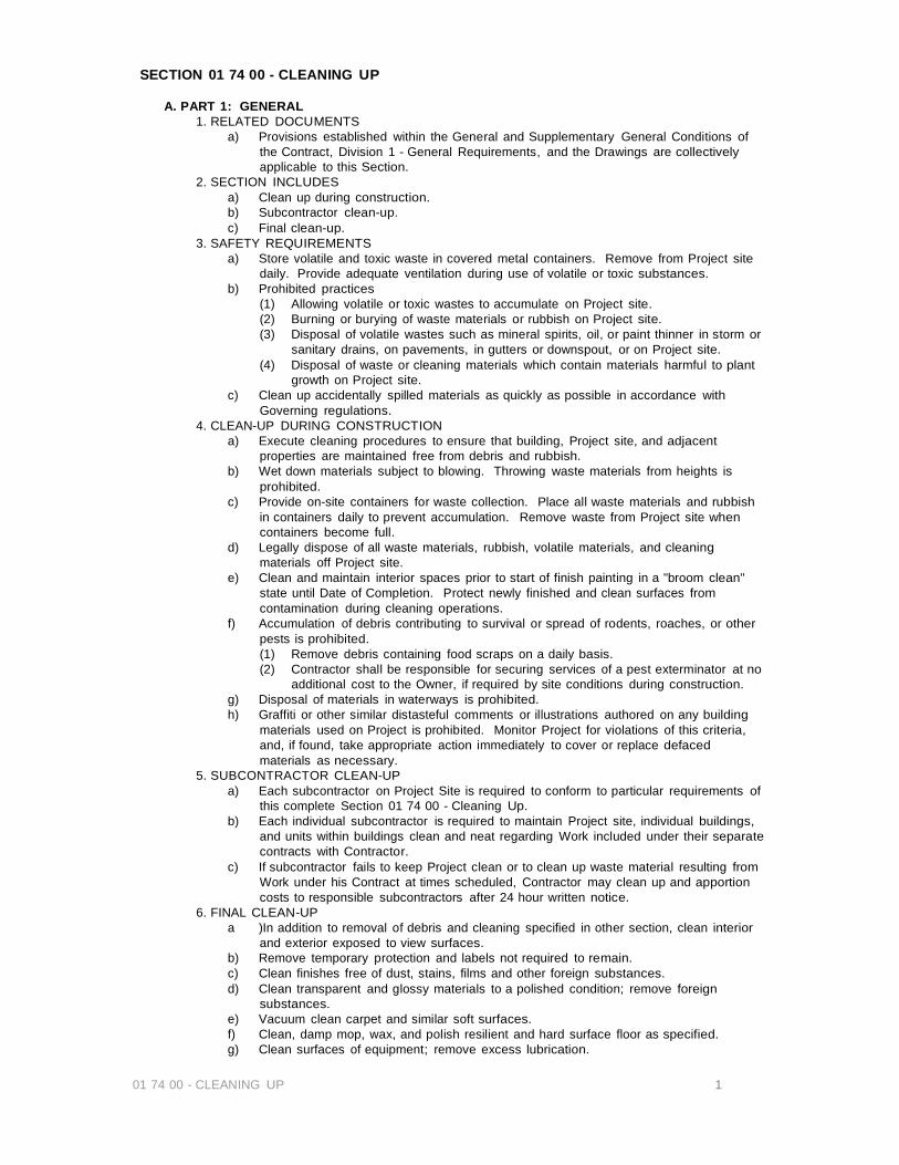
01 74 00 - CLEANING UP 1
SECTION 01 74 00 - CLEANING UP
A. PART 1: GENERAL 1. RELATED DOCUMENTS
a) Provisions established within the General and Supplementary General Conditions of the Contract, Division 1 - General Requirements, and the Drawings are collectively applicable to this Section.
2. SECTION INCLUDES a) Clean up during construction. b) Subcontractor clean-up. c) Final clean-up.
3. SAFETY REQUIREMENTS a) Store volatile and toxic waste in covered metal containers. Remove from Project site
daily. Provide adequate ventilation during use of volatile or toxic substances. b) Prohibited practices
(1) Allowing volatile or toxic wastes to accumulate on Project site. (2) Burning or burying of waste materials or rubbish on Project site. (3) Disposal of volatile wastes such as mineral spirits, oil, or paint thinner in storm or
sanitary drains, on pavements, in gutters or downspout, or on Project site. (4) Disposal of waste or cleaning materials which contain materials harmful to plant
growth on Project site. c) Clean up accidentally spilled materials as quickly as possible in accordance with
Governing regulations. 4. CLEAN-UP DURING CONSTRUCTION
a) Execute cleaning procedures to ensure that building, Project site, and adjacent properties are maintained free from debris and rubbish.
b) Wet down materials subject to blowing. Throwing waste materials from heights is prohibited.
c) Provide on-site containers for waste collection. Place all waste materials and rubbish in containers daily to prevent accumulation. Remove waste from Project site when containers become full.
d) Legally dispose of all waste materials, rubbish, volatile materials, and cleaning materials off Project site.
e) Clean and maintain interior spaces prior to start of finish painting in a "broom clean" state until Date of Completion. Protect newly finished and clean surfaces from contamination during cleaning operations.
f) Accumulation of debris contributing to survival or spread of rodents, roaches, or other pests is prohibited. (1) Remove debris containing food scraps on a daily basis. (2) Contractor shall be responsible for securing services of a pest exterminator at no
additional cost to the Owner, if required by site conditions during construction. g) Disposal of materials in waterways is prohibited. h) Graffiti or other similar distasteful comments or illustrations authored on any building
materials used on Project is prohibited. Monitor Project for violations of this criteria, and, if found, take appropriate action immediately to cover or replace defaced materials as necessary.
5. SUBCONTRACTOR CLEAN-UP a) Each subcontractor on Project Site is required to conform to particular requirements of
this complete Section 01 74 00 - Cleaning Up. b) Each individual subcontractor is required to maintain Project site, individual buildings,
and units within buildings clean and neat regarding Work included under their separate contracts with Contractor.
c) If subcontractor fails to keep Project clean or to clean up waste material resulting from Work under his Contract at times scheduled, Contractor may clean up and apportion costs to responsible subcontractors after 24 hour written notice.
6. FINAL CLEAN-UP a )In addition to removal of debris and cleaning specified in other section, clean interior
and exterior exposed to view surfaces. b) Remove temporary protection and labels not required to remain. c) Clean finishes free of dust, stains, films and other foreign substances. d) Clean transparent and glossy materials to a polished condition; remove foreign
substances. e) Vacuum clean carpet and similar soft surfaces. f) Clean, damp mop, wax, and polish resilient and hard surface floor as specified. g) Clean surfaces of equipment; remove excess lubrication.

01 74 00 - CLEANING UP 2
h) Clean plumbing fixtures, and food service equipment, to a sanitary condition. i) Clean permanent filters of ventilating equipment and replace disposable filters when
units have been operated during construction; in addition, clean ducts, blowers, and coils when units have been operated without filters during construction.
j) Clean light fixtures and lamps. k) Maintain cleaning until Final Completion. l) Remove waster, foreign matter, and debris from roofs, and drainage systems. m) Remove waste, debris, and surplus materials from site. Clean grounds; remove
stains, spills and foreign substances from paved areas and sweep clean. Rake clean other exterior surfaces.
B. PART 2: PRODUCTS
Not applicable to this section.
A. PART 3: EXECUTION Not applicable to this section.
END OF SECTION 01 74 00 - CLE ANING UP

SECTION 01 78 00 – CLOSEOUT SUBMITTALS: WARRANTIES AND BONDS
A. PART 1: GENERAL 1. RELATED DOCUMENTS
a) Provisions established within the General and Supplementary General Conditions of the Contract, Division 1 - General Requirements, and the Drawings are collectively applicable to this Section.
2. SECTION INCLUDES a) Preparation and submittal of warranties and bonds. b) Schedule of submittals.
3. FORM OF SUBMITTAL a) Bind in commercial quality 8-1/2 x 11-inch three-ring binders, with hardback,
cleanable, plastic covers. b) Label cover of each binder with typed or printed title WARRANTIES AND BONDS,
with title of Project; name, address and telephone number of Contractor; and name of responsible principal.
c) Table of Contents: Neatly typed, in the sequence of the Table of Contents of the Project Manual, with each item identified with the number and title of the specification section in which specified, and the name of Product or work item.
d) Separate each warranty or bond with index tab sheets keyed to the Table of Contents listing. Provide full information, using separate typed sheets as necessary. List subcontractor, supplier, and manufacturer, with name, address, and telephone number of responsible principal.
4. PREPARATION OF SUBMITTALS a) Obtain warranties and bonds, executed in duplicate by responsible subcontractors,
suppliers, and manufacturers, within ten (10) days after completion of the applicable item of work. Except for items put into use with Owner's Representative permission, leave date of beginning of time of warranty until the Date of Completion is determined.
b) Verify that documents are in proper form, contain full information, and are notarized. c) Co-execute submittals when required. d) Retain warranties and bonds until time specified for submittal.
5. TIME OF SUBMITTALS a) Submit within (60) days of Notice to Proceed:
(1) Binder (2) Table of Contents (3) Indexed Dividers
b) For equipment or component parts of equipment put into service during construction with Owner's Representative permission, submit documents within ten (10) days after acceptance.
c) Make other submittals within ten (10) days after Date of Completion, prior to final Application for Payment.
d) For items of Work when acceptance is delayed beyond Date of Completion, submit within ten (10) days after acceptance, listing the date of acceptance as the beginning of the warranty period.
B. PART 2: PRODUCTS
a)Not applicable to this section.
C. PART 3: EXECUTION a)Not applicable to this section.
END SECTION 01 78 00 – CLOSEOUT SUBMITTALS: WARRANTIES AND BONDS
SECTION 01 78 00 – CLOSEOUT SUBMITTALS: WARRANTIES AND BONDS

01 78 23 - OPERATION AND MAINTENANCE DATA 1
SECTION 01 78 23 - OPERATION AND MAINTENANCE DATA
A. PART 1: GENERAL 1.RELATED DOCUMENTS
a) Provisions established within the General and Supplemental General Conditions of the Contract, Division 1 - General Requirements, and the Drawings are collectively applicable to this Section.
2. SECTION INCLUDES a) Format and content of manuals. b) Instruction of Owner's personnel.
3. QUALITY ASSURANCE a) Prepared instructions and data by personnel experienced in maintenance and
operation of described products. 4. FORMAT
a) Prepare data in the form of an instructional manual.. b) Binders: Commercial quality, 8-1/2 x 11-inch three-ring binders with hardback,
cleanable, plastic covers; 3-inch maximum ring size. When multiple binders are used, correlate data into related consistent groupings.
c) Cover: Identify each binder with typed or printed title OPERATION AND MAINTENANCE INSTRUCTIONS; title of Project and subject matter of contents.
d) Arrange content by systems, under section numbers and sequence of Table of Contents of this Project Manual.
e) Provide tabbed fly leaf for each separate product and system, with typed description of product and major component parts of equipment.
f) Text: Manufacturer's printed data, or typewritten data on 20-pound paper. g) Drawings: Provide with reinforced punched binder tab. Bind in with text; fold larger
drawings to size of text pages. 5. CONTENTS
a) Table of Contents: Provide title of Project; names, addresses, and telephone numbers of Architect/Engineer and Contractor with name of responsible parties; schedule of products and systems, indexed to content of the volume.
b) For Each Product or System: List names, addresses, and telephone numbers of subcontractors and suppliers, including local source of supplies and replacement parts.
c) Product Data: Mark each sheet to clearly identify specific products and component parts, and data applicable to installation; delete inapplicable information.
d) Drawings: Supplement product data to illustrate relations of component parts of equipment and systems, to show control and flow diagrams. Do not use Project Record Document as maintenance drawings.
e) Typed Text: As required to supplement product date. Provide logical sequence of instructions for each procedures, incorporating manufacturer's instructions specified in Section 01 45 00 - Contract Quality Control.
f) Warranties and Bonds: Bind in copy of each. 6. MANUAL FOR MATERIALS AND FINISHES
a) Building Products, Applied Materials, and Finishes: Include product data, with catalog number, size, composition, and color and texture designations. Provide information for re-ordering custom manufactured products.
b) Instruction for Care and Maintenance: Include manufacturer's recommendations for cleaning agents and methods, precautions against detrimental agents and methods, and recommended schedule for cleaning and maintenance.
c) Moisture-protection and Weather-exposed Products: Include product data listing applicable reference standards, chemical composition, and details of installation. Provide recommendations for inspections, maintenance, and repair.
d) Additional Requirements: As specified in individual Specifications sections. e) Provide a listing of Table of Contents for design data, with tabbed fly sheet and space
for insertion of data. 7. MANUAL FOR EQUIPMENT AND SYSTEMS
a) Each Item of Equipment and Each System: Include description of unit or system, and component parts, and number of replaceable parts.
b) Panelboard Circuit Directories: Provide electrical service characteristics, controls and communications.
c) Operating Procedures: Include start-up, break-in, and routine normal operating instructions and sequences. Include regulation, control, stopping, shut-down, and emergency instructions. Include summer, winter, and any special operating
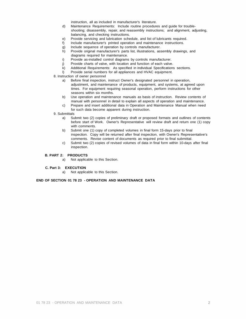
01 78 23 - OPERATION AND MAINTENANCE DATA 2
instruction, all as included in manufacturer's literature. d) Maintenance Requirements: Include routine procedures and guide for trouble-
shooting; disassembly, repair, and reassembly instructions; and alignment, adjusting, balancing, and checking instructions.
e) Provide servicing and lubrication schedule, and list of lubricants required. f) Include manufacturer's printed operation and maintenance instructions. g) Include sequence of operation by controls manufacturer. h) Provide original manufacturer's parts list, illustrations, assembly drawings, and
diagrams required for maintenance. i) Provide as-installed control diagrams by controls manufacturer. j) Provide charts of valve, with location and function of each valve. k) Additional Requirements: As specified in individual Specifications sections. l) Provide serial numbers for all appliances and HVAC equipment.
8. Instruction of owner personnel a) Before final inspection, instruct Owner's designated personnel in operation,
adjustment, and maintenance of products, equipment, and systems, at agreed upon times. For equipment requiring seasonal operation, perform instructions for other seasons within six months.
b) Use operation and maintenance manuals as basis of instruction. Review contents of manual with personnel in detail to explain all aspects of operation and maintenance.
c) Prepare and insert additional data in Operation and Maintenance Manual when need for such data become apparent during instruction.
9. Submittals a) Submit two (2) copies of preliminary draft or proposed formats and outlines of contents
before start of Work. Owner's Representative will review draft and return one (1) copy with comments.
b) Submit one (1) copy of completed volumes in final form 15-days prior to final inspection. Copy will be returned after final inspection, with Owner's Representative's comments. Revise content of documents as required prior to final submittal.
c) Submit two (2) copies of revised volumes of data in final form within 10-days after final inspection.
B. PART 2: PRODUCTS
a) Not applicable to this Section.
C. Part 3: EXECUTION a) Not applicable to this Section.
END OF SECTION 01 78 23 - OPERATION AND MAINTENANCE DATA

SECTION 01 78 33 - BONDS AND CERTIFICATIONS
A. PART 1: GENERAL
1. Performance Bond, AIA Document A312 (latest edition) 2. Labor and Material Payment Bond, AIA Document A312 (latest edition)
END OF SECTION 01 78 33 - BONDS AND CERTIFICATIONS
01 78 33 – BONDS AND CERTIFICATIONS

01 78 39 – Project Record Documents 1
I. SECTION 01 78 39 - PROJECT RECORD DOCUMENTS
A. PART 1: GENERAL 1. RELATED DOCUMENTS
a) Provisions established within the General and Supplementary General Conditions of the Contract, Division 1 - General Requirements, and the Drawings are collectively applicable to this Section.
2. SECTION INCLUDES a) Maintenance of Record Documents and Samples. b) Submittal of Record Documents and Samples. c) Submittal of Product Data and Contact List.
3. MAINTENANCE OF DOCUMENTS AND SAMPLES a) In addition to requirements in General Conditions, maintain at the site one (1) record copy of:
(1) Contract Drawings and plan schedule. (2) Specifications. (3) Addenda. (4) Change Orders and other modifications of the Contract. (5) Reviewed Submittals. (6) Field test records. (7) Inspection certificates. (8) Manufacturer's certificates. (9) RFI & logs. (10) SK drawings and logs.
b) Store Record Documents and samples in Field Office apart from documents used for construction. Provide files, racks, and secure storage for Record Documents and samples.
c) Label and file Record Documents and samples in accordance with section number listings in Table of Contents of this Project Manual. Label each document "PROJECT RECORD" in neat, large, printed letters.
d) Maintain Record Documents in a clean, dry and legible condition. Do not use Record Documents for construction purposes.
e) Keep Record Documents and samples available for inspection by Owner's Representative and Inspecting Consultant.
4. RECORDING a) Record information on a set of blue line opaque drawings, and in a copy of a Project Manual. At
completion of the project, transfer information from the blue line prints onto reverse reading mylar reproducibles.
b) Provide felt tip marking pens, maintaining separate colors for each major system, for record information.
c) Record information concurrently with construction progress. Do not conceal any work until required information is recorded.
d) Contract Drawings and Shop Drawings: Legibly mark each item to record actual construction, including: (1) Measured horizontal locations for water, storm drainage, and sanitary sewer drainage
piping and measured horizontal and vertical locations for all other underground utilities, referenced to permanent surface improvements.
(2) Measured locations of internal utilities and appurtenances concealed in construction, referenced to visible and accessible features of construction.
(3) Field changes of dimension and detail. (4) Changes made by Modifications, including all RFI's. (5) Details not on original Contract Drawings or SK Drawings. (6) References to related shop drawings and modifications.
e) Other Documents: Maintain manufacturer's certifications, inspection certifications, field test records, and other documents required by individual specification sections.
5. SUBMITTALS a) At Contract closeout, deliver Record Documents and samples under provisions of Section 00
70 00 - Contract Closeout. (1) Transmit with cover letter in duplicate, listing:
(a) Date. (b) Project title and number. (c) Contractor's name, address, and telephone number. (d) Number and title of each Record Document. (e) Signature of Contractor or authorized representative.

01 78 39 – Project Record Documents 2
b) Product Data and Contact List (1) Preparation of Submittals
(a) Table of Contents: Provide title of Project; names, addresses, and telephone numbers of Architect/Engineer and Contractor with name of responsible parties; schedule of products and systems, indexed to content of the volume.
(b )For Each Product or System: List names, addresses and telephone numbers of subcontractors and suppliers, including local source of supplies and replacement parts.
(c) Product Data: Mark each sheet to clearly identify specific products and component parts, and data applicable to installation; delete inapplicable information.
(d) Drawings: Supplement product data to illustrate relations of component parts of equipment and systems, to show control and flow diagrams. Do not use Project Record Documents as informational drawings.
(e) Typed Text: As required to supplement product data. Provide logical sequence of instructions for each procedure, incorporating manufacturer's instructions specified in Section 01 45 00 - Quality Control.
(f) Warranties and Bonds: Bind in copy of each. See Section 01 78 00 - Warranties and Bonds.
(2) Form of Submittals (a) Prepare data in the form of an instructional manual. (b) Binders: Commercial quality, 8-1/2 x 11-inch three-ring binders with hardback,
cleanable, plastic covers; 3-inch maximum ring size. When multiple binders are used, correlate data into related consistent groupings.
(c) Cover: Identify each binder with typed or printed title "Product DATA and Contact List"; list title of Project and identify subject matter of contents.
(d) Arrange content by systems, under section numbers and sequence of Table of Contents of this Project Manual.
(e) Provide tabbed fly leaf for each separate product and system, with typed description of product and major component parts of equipment.
(f) Text: Manufacturer's printed data, or typewritten data on 20-pound paper. (g) Drawings: Provide with reinforced punched binder tab. Bind in with text; fold larger
drawings to size of text pages. (3) Time of Submittals
(a) Submit two (2) copies of preliminary draft of proposed formats and outlines of contents within 60 days of Notice to Proceed. Owner's Representative will review draft and return one (1) copy with comments.
(b) Submit one (1) copy of completed volumes in final form 15-days prior to final inspection. Copy will be returned after final inspection, with Owner's Representative's comments. Revise content of documents as required prior to final submittal.
(c) Submit two (2) copies of revised volumes of data in final form within 10-days after final inspection.
B. PART 2: PRODUCTS Not applicable to this Section.
C. PART 3: EXECUTION Not applicable to this Section.
D. Part 4: FORMS Forms may be obtained from Owner's Representative.
I. END OF SECTION 01 78 39 - PROJECT RECORD DOCUMENTS

SECTION 01 93 00 – FACILITY MAINTENANCE: SPARE PARTS, OVERAGES AND MAINTENANCE MATERIALS
A. PART 1: GENERAL
1. RELATED DOCUMENTS a) Provisions established within the General and Supplementary General Conditions of
the Contract, Division 1 - General Requirements, and the Drawings are collectively applicable to this Section.
2. REQUIREMENTS INCLUDED a) Products required. b) Storage and delivery of products.
3. Products required a) Provide quantities of products, spare parts, maintenance tools, and maintenance
materials specified in individual section to be provided to Owner's Representative in addition to that required for completion of Work.
b) Products: Indentical to those installed in the Work. Include quantities in original purchase from manufacturers to avoid variations in manufacture.
4. Storage , Maintenance a) Store products with products to be installed in the Work, under provisions of Section
01 66 00-Delivery, Storage and Handling. b) When adequate, secure storage facilities are available at site, capable of maintaining
conditions required for storage and not required for Contract work or storage, or for Owner's needs, spare products may be stored in available space.
c) Maintain spare products in original containers with labels intact and legible, until delivery to Owner.
5. Delivery a) Coordinate with Owner's Representative: Deliver and unload spare products to Owner
at Project site and obtain receipt prior to final payment. b) For portions of Project accepted and occupied by Owner prior to Completion, deliver a
proportional part of spare products to Owner's Representative; obtain receipt.
END OF SECTION 01 93 00 – Facility Maintenance: SPARE PARTS, OVERAGES AND MAINTENANCE MATERIALS
01 93 00 – Facility Maintenance: SPARE PARTS, OVERAGES AND MAINTENANCE MATERIALS/

02 56 19.13 Fluid-Applied Gas Barrier Version 1.30 2
Section 02 56 19.13 Fluid-Applied Gas Barrier Version 1.30
PART 1 – GENERAL 1.1 RELATED DOCUMENTS A. Drawings and general provisions of the contract, including general and supplementary conditions and
Division 1 specification sections, apply to this section.
1.2 SUMMARY A. This section includes the following:
1. Substrate preparation: 2. Vapor intrusion barrier components: 3. Seam sealer and accessories.
B. Related Sections: The following sections contain requirements that relate to this section: 1. Division 2 Section “Earthwork”, “Pipe Materials”, “Sub-drainage Systems”, “Gas Collection Systems” 2. Division 3 Section “Cast-in-Place Concrete” for concrete placement, curing, and finishing: 3. Division 5 Section “Expansion Joint Cover Assemblies”, for expansion-joint covers assemblies
and installation.
1.3 PERFORMANCE REQUIREMENTS A. General: Provide a vapor intrusion barrier system that prevents the passage of methane gas and/or
volatile organic compound vapors and complies with physical requirements as demonstrated by testing performed by an independent testing agency of manufacturer’s current vapor intrusion barrier formulations and system design.
1.4 SUBMITTALS
A. Submit product data for each type of vapor intrusion barrier, including manufacturer’s printed instructions for evaluating and preparing the substrate, technical data, and tested physical and performance properties.
B. Project Data - Submit shop drawings showing extent of vapor intrusion barrier, including details for overlaps, flashing, penetrations, and other termination conditions.
C. Samples – Submit representative samples of the following for approval: 1. Vapor intrusion barrier components.
D. Certified Installer Certificates – Submit certificates signed by manufacturer certifying that installers comply with requirements under the “Quality Assurance” article.
1.5 QUALITY ASSURANCE
A. Installer Qualifications: Engage an experienced installer who has been trained and certified in writing by the membrane manufacturer, Land Science TechnologiesTM for the installation of the Geo-Seal® System.
B. Manufacturer Qualification: Obtain vapor intrusion barrier materials and system components from a single manufacturer source Land Science Technologies.
C. Field Sample: Apply vapor intrusion barrier system field sample to 100 ft2 (9.3 m2) of field area demonstrate application, detailing, thickness, texture, and standard of workmanship. 1. Notify engineer or special inspector one week in advance of the dates and times when field sample
will be prepared. 2. If engineer or special inspector determines that field sample, does not meet requirements, reapply
field sample until field sample is approved. 3. Retain and maintain approved field sample during construction in an undisturbed condition as a
standard for judging the completed methane and vapor intrusion barrier. An undamaged field sample may become part of the completed work.
D. Pre-installation Conference: A pre-installation conference shall be held prior to application of the vapor intrusion barrier system to assure proper site and installation conditions, to include contractor, applicator, architect/engineer, other trades influenced by vapor intrusion barrier installation and special inspector (if any).
1.6 DELIVERY, STORAGE, AND HANDLING
A. Deliver materials to project site as specified by manufacturer labeled with manufacturer’s name, product brand name and type, date of manufacture, shelf life, and directions for storing and mixing with other components.
B. Store materials as specified by the manufacturer in a clean, dry, protected location and within the temperature range required by manufacturer. Protect stored materials from direct sunlight. If freezing temperatures are expected, necessary steps should be taken to prevent the freezing of the Geo-Seal CORE and Geo-Seal CORE Detail components.
C. Remove and replace material that cannot be applied within its stated shelf life.
1.7 PROJECT CONDITIONS A. Protect all adjacent areas not to be installed on. Where necessary, apply masking to prevent staining of
surfaces to remain exposed wherever membrane abuts to other finish surfaces. B. Perform work only when existing and forecasted weather conditions are within manufacturer’s
recommendations for the material and application method used. C. Minimum clearance of 24 inches is required for application of product. For areas with less than 24-inch
clearance, the membrane may be applied by hand using Geo-Seal CORE Detail. D. Ambient temperature shall be within manufacturer’s specifications. (Greater than +45oF/+7oC.) Consult
Manufacturer for the proper requirements when desiring to apply Geo-Seal CORE below 45oF/7oC.

02 56 19.13 Fluid-Applied Gas Barrier Version 1.30 3
E. All plumbing, electrical, mechanical and structural items to be under or passing through the vapor intrusion barrier system shall be positively secured in their proper positions and appropriately protected prior to membrane application.
F. Vapor intrusion barrier shall be installed before placement of fill material and reinforcing steel. When not possible, all exposed reinforcing steel shall be masked by general contractor prior to membrane application.
G. Stakes used to secure the concrete forms shall not penetrate the vapor intrusion barrier system after it has been installed. If stakes need to puncture the vapor intrusion barrier system after it has been installed, the necessary repairs need to be made by a certified Geo-Seal applicator. To confirm the staking procedure is in agreement with the manufactures recommendation, contact Land Science Technologies.
1.8 WARRANTY
A. General Warranty: The special warranty specified in this article shall not deprive the owner of other rights the owner may have under other provisions of the contract documents, and shall be in addition to, and run concurrent with, other warranties made by the contractor under requirements of the contract documents.
B. Special Warranty: Submit a written warranty signed by vapor intrusion barrier manufacturer agreeing to repair or replace vapor intrusion barrier that does not meet requirements or that does not remain methane gas and/or volatile organic compound vapor tight within the specified warranty period. Warranty does not include failure of vapor intrusion barrier due to failure of substrate prepared and treated according to requirements or formation of new joints and cracks in the attached to structures that exceed 1/16 inch (1.58 mm) in width. 1. Warranty Period: 1 year after date of substantial completion. Longer warranty periods are available upon request to the manufacturer.
C. Labor and material warranties are available upon request to the manufacturer.
PART 2 – PRODUCTS 2.1 MANUFACTURERS A. Geo-Seal; Land Science Technologies (949) 481-8118
2.2 VAPOR INTRUSION BARRIER SPRAY MATERIALS A. Fluid applied vapor intrusion barrier system – Geo-Seal CORE; a single course, high build, polymer
modified, asphalt emulsion. Waterborne and spray applied at ambient temperatures. A nominal thickness of 60 dry mils, unless specified otherwise. Non-toxic and odorless. Geo-Seal CORE Detail has similar properties with greater viscosity and is roller or brush applied. Manufactured by Land Science Technologies. 1. Geo-Seal BASE sheet layer 2. Geo-Seal CORE spray layer 3. Geo-Seal CORE Detail Geo-Seal BOND protection layer

02 56 19.13 Fluid-Applied Gas Barrier Version 1.30 4
2.3 VAPOR INTRUSION BARRIER SHEET MATERIALS
A. The Geo-Seal BASE layer and Geo-Seal BOND layer are chemically resistant sheets comprised of a 5 mil high densitypolyethylene sheet thermally bonded to a 3 oz non woven geotextile.
B. Sheet Course Usage 1. As foundation base layer, use Geo-Seal BASE course and/or other base sheet as required or approved by the 2. As top protective layer, use Geo-Seal BOND layer and/or other protection as required or approved by the manufacturer. Temperature Effect: manufacturer.
2.4 AXILLARY MATERIALS A. Sheet Flashing: 60-mil reinforced modified asphalt sheet good with double-sided adhesive. B. Reinforcing Strip: Manufacturer’s recommended polypropylene and polyester fabric. C. Gas Venting Materials: Geo-Seal Vapor-Vent HD or Geo-Seal Vapor-Vent Poly, and associated fittings. D. Seam Detailing Sealant Mastic: Geo-Seal CORE Detail, a high or medium viscosity polymer modified
water based asphalt material.
PART 3 – EXECUTION A. Examine substrates, areas, and conditions under which vapor intrusion barrier will be applied, with
installer present, for compliance with requirements. Do not proceed with installation until unsatisfactory conditions have been corrected.
3.2 SUBGRADE SURFACE PARSETMPABR2A5T8I2OTND A. Verify substrate is prepared according to manufacturer’s recommendations. On a horizontal surface, the
substrate should be free from material that can potentially puncture the vapor intrusion barrier. Additional protection or cushion layers might be required if the earth or gravel substrate contains too many jagged points and edges that could puncture one or more of the system components. Contact manufacturer to confirm substrate is within manufactures recommendations.
B. Geo-Seal can accommodate a wide range of substrates, including but not limited to compacted earth, sand, aggregate, and mudslabs.

02 56 19.13 Fluid-Applied Gas Barrier Version 1.30 5
the Geo- Seal BASE. Remove any debris from substrate that can potentially puncture the Geo-Seal system prior to application. 2. Sand: A sand subgrade requires no additional preparation, provided any material that can potentially puncture the Geo- Seal BASE layer is not present. 3. Aggregate: Contact the manufacturer to ensure the aggregate layer will not be detrimental to the membrane. The gravel layer must be compacted and rolled flat. Ideally a 3⁄4” minus gravel layer with rounded edges should be specified; however the Geo-Seal system can accommodate a wide variety of different substrates. Contact Land Science Technologies if there are questions regarding the compatibility of Geo-Seal and the utilized substrate. Exercise caution when specifying pea gravel under the membrane, if not compacted properly, pea gravel can become an unstable substrate. 4 Mudslabs: The use of a mubslab under the Geo-Seal system is acceptable, contact Land Science Technologies for job specific requirements.
C. Mask off adjoining surface not receiving the vapor intrusion barrier system to prevent the spillage or over spray affecting other construction.
D. Earth, sand or gravel subgrades should be prepared and compacted to local building code requirements.
3.3 CONCRETE SURFACE PREPARATION A. Clean and prepare concrete surface to manufacturer’s recommendations. In general, only apply the Geo-Seal CORE
material to dry, clean and uniform substrates. Concrete surfaces must be a light trowel, light broom or equivalent finish. Remove fins, ridges and other projections and fill honeycomb, aggregate pockets, grout joints and tie holes, and other voids with hydraulic
3.4 PREPARATIONS AND TREATMENT OF TERMINATIONS
A. Prepare the substrate surface in accordance with Section 3.3 of this document. Concrete surfaces that are not a light trowel, light broom or equivalent finish, will need to be repaired.
B. Terminations on horizontal and vertical surfaces should extend 6” onto the termination surface. Job specific conditions may prevent a 6” termination. In these conditions, contact manufacturer for recommendations.
C. Apply 30 mils of Geo-Seal CORE to the terminating surface and then embed the Geo-Seal BASE layer by pressing it firmly into the Geo-Seal CORE layer. Next, apply 60 mils of Geo-Seal CORE to the BASE layer. When complete, apply the Geo-Seal BOND layer. After the placement of the Geo-Seal BOND layer is complete, apply a final 30 mil seal of the Geo-Seal CORE layer over the edge of the termination. For further clarification, refer to the termination detail provided by manufacturer.
D. The stated termination process is appropriate for terminating the membrane onto exterior footings, pile caps, interior footings and grade beams. When terminating the membrane to stem walls or vertical surfaces the same process should be used.
3.5 PREPARATIONS AND TREATMENT OF PENETRATIONS
A. All pipe penetrations should be securely in place prior to the installation of the Geo-Seal system. Any loose penetrations should be secured prior to Geo-Seal application, as loose penetrations could potentially exert pressure on the membrane and damage the membrane after installation.
B. To properly seal around penetrations, cut a piece of the Geo-Seal BASE layer that will extend 6” beyond the outside perimeter of the penetration. Cut a hole in the Geo-Seal BASE layer just big enough to slide over the penetration, ensuring the Geo-Seal BASE layer fits snug against the penetration, this can be done by cutting an “X” no larger than the inside diameter of the penetration. There should not be a gap larger than a 1/8” between the Geo-Seal BASE layer and the penetration. Other methods can also be utilized, provided, there is not a gap larger than 1/8” between the Geo-Seal BASE layer and the penetration.
C. Seal the Geo-Seal BASE layer using Geo-Seal CORE or Geo-Seal CORE Detail to the underlying Geo-Seal BASE layer.
D. Apply one coat of Geo-Seal CORE Detail or Geo-Seal CORE spray to the Geo-Seal BASE layer and around the penetration at a thickness of 30 mils. Penetrations should be treated in a 6-inch radius around penetration and 3 inches onto penetrating object.
E. Embed a fabric reinforcing strip after the first application of the Geo-Seal CORE spray or Geo-Seal CORE Detail material and then apply a second 30 mil coat over the embedded joint reinforcing strip ensuring its complete saturation of the embedded strip and tight seal around the penetration.
F. After the placement of the Geo-Seal BOND layer, a cable tie should then be placed around the finished penetration. The cable tie should be snug, but not overly tight so as to slice into the finished seal.
OPTION: A final application of Geo-Seal CORE may be used to provide a finishing seal after the Geo-Seal BOND layer has been installed. NOTE: Metal or other slick penetration surfaces may require treatment in order to achieve proper adhesion. For plastic pipes, sand paper may be used to achieve a profile, an emery cloth is more appropriate for metal surfaces. An emery cloth should also be used to remove any rust on metal surfaces.
3.6 GEO-SEAL BASE LAYER INSTALLATION A. Install the Geo-Seal BASE layer over substrate material in one direction with six-inch overlaps and the geotextile
(fabric side) facing down. B. Secure the Geo-Seal BASE seams by applying 60 mils of Geo-Seal CORE between the 6” overlapped sheets with the
geotextile side down. C. Visually verify there are no gaps/fish-mouths in seams. D. For best results, install an equal amount of Geo-Seal BASE and Geo-Seal CORE in one day. Leaving unsprayed
Geo-Seal BASE overnight might allow excess moisture to collect on the Geo-Seal BASE. If excess moisture
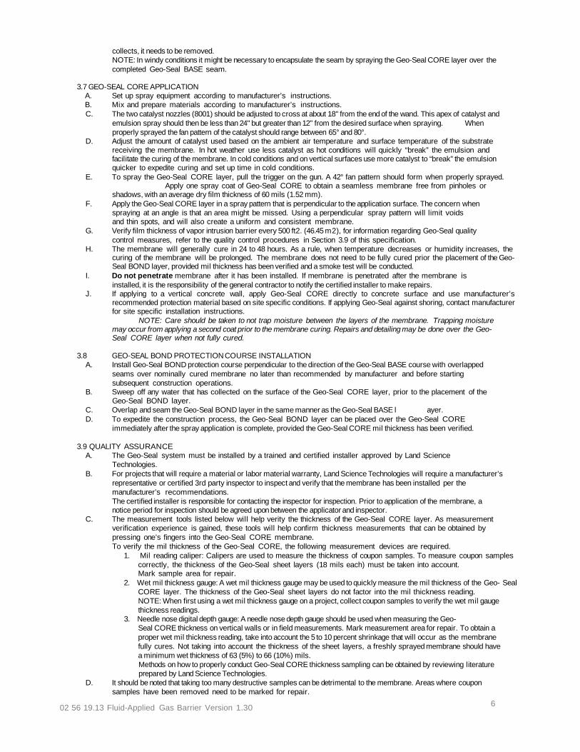
02 56 19.13 Fluid-Applied Gas Barrier Version 1.30 6
collects, it needs to be removed. NOTE: In windy conditions it might be necessary to encapsulate the seam by spraying the Geo-Seal CORE layer over the completed Geo-Seal BASE seam.
3.7 GEO-SEAL CORE APPLICATION
A. Set up spray equipment according to manufacturer’s instructions. B. Mix and prepare materials according to manufacturer’s instructions. C. The two catalyst nozzles (8001) should be adjusted to cross at about 18" from the end of the wand. This apex of catalyst and
emulsion spray should then be less than 24" but greater than 12” from the desired surface when spraying. When properly sprayed the fan pattern of the catalyst should range between 65° and 80°.
D. Adjust the amount of catalyst used based on the ambient air temperature and surface temperature of the substrate receiving the membrane. In hot weather use less catalyst as hot conditions will quickly “break” the emulsion and facilitate the curing of the membrane. In cold conditions and on vertical surfaces use more catalyst to “break” the emulsion quicker to expedite curing and set up time in cold conditions.
E. To spray the Geo-Seal CORE layer, pull the trigger on the gun. A 42° fan pattern should form when properly sprayed. Apply one spray coat of Geo-Seal CORE to obtain a seamless membrane free from pinholes or shadows, with an average dry film thickness of 60 mils (1.52 mm).
F. Apply the Geo-Seal CORE layer in a spray pattern that is perpendicular to the application surface. The concern when spraying at an angle is that an area might be missed. Using a perpendicular spray pattern will limit voids and thin spots, and will also create a uniform and consistent membrane.
G. Verify film thickness of vapor intrusion barrier every 500 ft2. (46.45 m2), for information regarding Geo-Seal quality control measures, refer to the quality control procedures in Section 3.9 of this specification.
H. The membrane will generally cure in 24 to 48 hours. As a rule, when temperature decreases or humidity increases, the curing of the membrane will be prolonged. The membrane does not need to be fully cured prior the placement of the Geo-Seal BOND layer, provided mil thickness has been verified and a smoke test will be conducted.
I. Do not penetrate membrane after it has been installed. If membrane is penetrated after the membrane is installed, it is the responsibility of the general contractor to notify the certified installer to make repairs.
J. If applying to a vertical concrete wall, apply Geo-Seal CORE directly to concrete surface and use manufacturer’s recommended protection material based on site specific conditions. If applying Geo-Seal against shoring, contact manufacturer for site specific installation instructions.
NOTE: Care should be taken to not trap moisture between the layers of the membrane. Trapping moisture may occur from applying a second coat prior to the membrane curing. Repairs and detailing may be done over the Geo-Seal CORE layer when not fully cured.
3.8 GEO-SEAL BOND PROTECTION COURSE INSTALLATION
A. Install Geo-Seal BOND protection course perpendicular to the direction of the Geo-Seal BASE course with overlapped seams over nominally cured membrane no later than recommended by manufacturer and before starting subsequent construction operations.
B. Sweep off any water that has collected on the surface of the Geo-Seal CORE layer, prior to the placement of the Geo-Seal BOND layer.
C. Overlap and seam the Geo-Seal BOND layer in the same manner as the Geo-Seal BASE l ayer. D. To expedite the construction process, the Geo-Seal BOND layer can be placed over the Geo-Seal CORE
immediately after the spray application is complete, provided the Geo-Seal CORE mil thickness has been verified.
3.9 QUALITY ASSURANCE A. The Geo-Seal system must be installed by a trained and certified installer approved by Land Science
Technologies. B. For projects that will require a material or labor material warranty, Land Science Technologies will require a manufacturer’s
representative or certified 3rd party inspector to inspect and verify that the membrane has been installed per the manufacturer’s recommendations. The certified installer is responsible for contacting the inspector for inspection. Prior to application of the membrane, a notice period for inspection should be agreed upon between the applicator and inspector.
C. The measurement tools listed below will help verity the thickness of the Geo-Seal CORE layer. As measurement verification experience is gained, these tools will help confirm thickness measurements that can be obtained by pressing one’s fingers into the Geo-Seal CORE membrane. To verify the mil thickness of the Geo-Seal CORE, the following measurement devices are required.
1. Mil reading caliper: Calipers are used to measure the thickness of coupon samples. To measure coupon samples correctly, the thickness of the Geo-Seal sheet layers (18 mils each) must be taken into account. Mark sample area for repair.
2. Wet mil thickness gauge: A wet mil thickness gauge may be used to quickly measure the mil thickness of the Geo- Seal CORE layer. The thickness of the Geo-Seal sheet layers do not factor into the mil thickness reading. NOTE: When first using a wet mil thickness gauge on a project, collect coupon samples to verify the wet mil gauge thickness readings.
3. Needle nose digital depth gauge: A needle nose depth gauge should be used when measuring the Geo- Seal CORE thickness on vertical walls or in field measurements. Mark measurement area for repair. To obtain a proper wet mil thickness reading, take into account the 5 to 10 percent shrinkage that will occur as the membrane fully cures. Not taking into account the thickness of the sheet layers, a freshly sprayed membrane should have a minimum wet thickness of 63 (5%) to 66 (10%) mils. Methods on how to properly conduct Geo-Seal CORE thickness sampling can be obtained by reviewing literature prepared by Land Science Technologies.
D. It should be noted that taking too many destructive samples can be detrimental to the membrane. Areas where coupon samples have been removed need to be marked for repair.

02 56 19.13 Fluid-Applied Gas Barrier Version 1.30 7
E. Smoke Testing is highly recommended and is the ideal way to test the seal created around penetrations and terminations. Smoke Testing is conducted by pumping non-toxic smoke underneath the Geo-Seal vapor intrusion barrier and then repairing the areas where smoke appears. Refer to smoke testing protocol provided by Land Science Technologies. For projects that will require a material or labor material warranty, Land Science Technologies will require a smoke test.
F. Visual inspections prior to placement of concrete, but after the installation of concrete reinforcing, is recommended to identify any punctures that may have occurred during the installation of rebar, post tension cables, etc. Punctures in the Geo-Seal system should be easy to indentify due to the color contrasting layers of the system.
End of Section 02 56 19.13 Fluid-Applied Gas Barrier
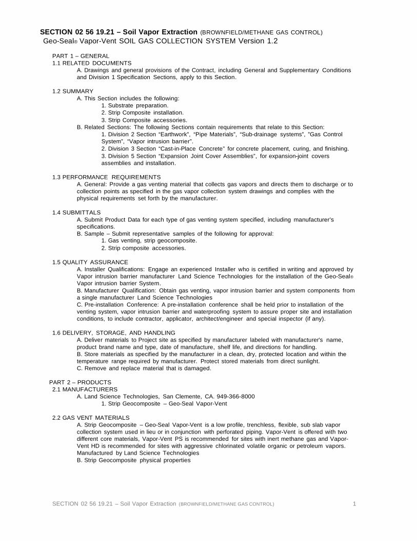
SECTION 02 56 19.21 – Soil Vapor Extraction (BROWNFIELD/METHANE GAS CONTROL) 1
SECTION 02 56 19.21 – Soil Vapor Extraction (BROWNFIELD/METHANE GAS CONTROL) Geo-Seal® Vapor-Vent SOIL GAS COLLECTION SYSTEM Version 1.2
PART 1 – GENERAL 1.1 RELATED DOCUMENTS
A. Drawings and general provisions of the Contract, including General and Supplementary Conditions and Division 1 Specification Sections, apply to this Section.
1.2 SUMMARY
A. This Section includes the following: 1. Substrate preparation. 2. Strip Composite installation. 3. Strip Composite accessories.
B. Related Sections: The following Sections contain requirements that relate to this Section: 1. Division 2 Section “Earthwork”, “Pipe Materials”, “Sub-drainage systems”, ”Gas Control System”, “Vapor intrusion barrier”. 2. Division 3 Section “Cast-in-Place Concrete” for concrete placement, curing, and finishing. 3. Division 5 Section “Expansion Joint Cover Assemblies”, for expansion-joint covers assemblies and installation.
1.3 PERFORMANCE REQUIREMENTS
A. General: Provide a gas venting material that collects gas vapors and directs them to discharge or to collection points as specified in the gas vapor collection system drawings and complies with the physical requirements set forth by the manufacturer.
1.4 SUBMITTALS
A. Submit Product Data for each type of gas venting system specified, including manufacturer’s specifications. B. Sample – Submit representative samples of the following for approval:
1. Gas venting, strip geocomposite. 2. Strip composite accessories.
1.5 QUALITY ASSURANCE
A. Installer Qualifications: Engage an experienced Installer who is certified in writing and approved by Vapor intrusion barrier manufacturer Land Science Technologies for the installation of the Geo-Seal®
Vapor intrusion barrier System. B. Manufacturer Qualification: Obtain gas venting, vapor intrusion barrier and system components from a single manufacturer Land Science Technologies C. Pre-installation Conference: A pre-installation conference shall be held prior to installation of the venting system, vapor intrusion barrier and waterproofing system to assure proper site and installation conditions, to include contractor, applicator, architect/engineer and special inspector (if any).
1.6 DELIVERY, STORAGE, AND HANDLING
A. Deliver materials to Project site as specified by manufacturer labeled with manufacturer’s name, product brand name and type, date of manufacture, shelf life, and directions for handling. B. Store materials as specified by the manufacturer in a clean, dry, protected location and within the temperature range required by manufacturer. Protect stored materials from direct sunlight. C. Remove and replace material that is damaged.
PART 2 – PRODUCTS 2.1 MANUFACTURERS
A. Land Science Technologies, San Clemente, CA. 949-366-8000 1. Strip Geocomposite – Geo-Seal Vapor-Vent
2.2 GAS VENT MATERIALS
A. Strip Geocomposite – Geo-Seal Vapor-Vent is a low profile, trenchless, flexible, sub slab vapor collection system used in lieu or in conjunction with perforated piping. Vapor-Vent is offered with two different core materials, Vapor-Vent PS is recommended for sites with inert methane gas and Vapor- Vent HD is recommended for sites with aggressive chlorinated volatile organic or petroleum vapors. Manufactured by Land Science Technologies B. Strip Geocomposite physical properties

SECTION 02 56 19.21 – Soil Vapor Extraction (BROWNFIELD/METHANE GAS CONTROL) 2
VENT PROPERTIES TEST METHOD VAPOR-VENT PS VAPOR-VENT HD Material Polystyrene HDPE Comprehensive Strength ASTM D-1621 9,000 lbs / ft2 9,200 lbs / ft2 Shear Strength ASTM D-1621 9,500 lbs / ft2 N/A Peel Strength ASTM D-1876 38 lbs / ft 35 lbs / ft Fungus Resistance (core) ASTM G-21 No Growth No Growth In-plane flow (Hydraulic gradient-0.1, loading-10 psi)
ASTM D-4716 21 gpm / ft of width 21 gpm / ft of width
Unobstructed inflow area Pavement side
85% 85%
Chemical Resistance N/A Excellent FABRIC PROPERTIES TEST METHOD VAPOR-VENT-PS VAPOR-VENT-HD Weight ASTM D-3776 4.0 oz. 4.5 oz. Grab Tensile Strength ASTM D-4632 115 lbs. 120 lbs. Puncture Strength ASTM D-3787 70 psi 65 psi Trapezoidal Tear ASTM D-4533 50 lbs. 30 lbs. Mullen Burst Strength ASTM D-3786 240 psi 50 psi Elongation ASTM D-4632 50% 50% EOS (AOS) ASTM D-4751 80 70 Permeability ASTM D-4491 20 cm/sec 21 cm / sec Flow Rate ASTM D-4491 170 gpm / ft2 135 gpm / ft2 UV Stability (500 hours) ASTM D-4355 85% Retained 70% Retained Fungus Resistance ASTM D-G21 No Growth No Growth DIMENSIONAL DATA Thickness 1” 1” Standard Widths 12” 12” Roll Length 150 ft 150 ft Roll Diameter 7 ft 7 ft Roll Weight 60 lbs 60 lbs
2.3 AUXILIARY MATERIALS A. Geo-Seal Vapor-Vent pipe reducers. B. Reinforced Tape.
PART 3 – EXECUTION
3.1 EXAMINATION A. Examine substrates, areas, and conditions under which gas vent system will be installed, with installer present, for compliance with requirements. Do not proceed with installation until unsatisfactory conditions have been corrected.
3.2 SUBSTRATE PREPARATION A. Verify substrate is prepared according to project requirements.
3.3 PREPARATION FOR STRIP COMPOSITE A. Mark the layout of strip geocomposite per layout design developed by engineer.
3.4 STRIP GEOCOMPOSITE INSTALLATION A. Install Geo-Seal Vapor-Vent over substrate material where designated on drawings with the flat base of the core placed down and shall be overlapped in accordance with manufacturer’s recommendations. B. At areas where Geo-Seal Vapor-Vent strips intersect cut and fold back fabric to expose the dimpled core. Arrange the strips so that the top strip interconnects into the bottom strip. Unfold fabric to cover the core and use reinforcing tape, as approved by the manufacturer, to seal the connection to prevent sand or gravel from entering the core. C. When crossing Geo-Seal Vapor-Vent over footings or grade beams, consult with the specifying environmental engineer and structural engineer for appropriate use and placement of solid pipe materials. Place solid pipe over or through concrete surface and attach a Geo-Seal Vapor-Vent pipe reducer at both ends of the pipe before connecting the Geo-Seal Vapor-Vent to the pipe reducer. Seal the Geo-Seal Vapor-Vent to the Geo-Seal Vapor-Vent pipe reducer using fabric reinforcement tape. Refer to Vapor-Vent detail provided by Land Science Technologies. D. Place vent risers per specifying engineer’s project specifications. Connect Geo-Seal Vapor-Vent to Geo-Seal Vapor-Vent pipe reducer and seal with fabric reinforced tape. Use Geo-Seal Vapor-Vent pipe reducer with the specified diameter piping as shown on system drawings.
3.5 PLACEMENT OF OVERLYING AND ADJACENT MATERIALS A. All overlying and adjacent material shall be placed or installed using approved procedures and guidelines to prevent damage to the strip geocomposite. B. Equipment shall not be directly driven over and stakes or any other materials may not be driven through the strip geocomposite.
END SECTION 02 56 19.21

SECTION 03 30 00 - CAST-IN-PLACE CONCRETE
Page
1
SECTION 03 30 00 - CAST-IN-PLACE CONCRETE PART 1 GENERAL
1.01 RELATED DOCUMENTS
A. Drawings and general provisions of the Contract, including General and Supplementary Conditions and Division 1 Specification Sections, apply to this Section.
1.02 SUMMARY
A. This Section specifies cast-in place concrete, including formwork, reinforcing, mix design, placement procedures, and finishes for the building.
B. Cast-in-place concrete includes the following: 1. Foundations and footings. 2. Slabs-on-grade. 3. Equipment pads and bases.
1.03 SUBMITTALS
A. General: Submit the following according to Conditions of the Contract and Division 1 Specification Sections.
B. Product data for proprietary materials and items, including reinforcement and forming accessories, admixtures, patching compounds, waterstops, joint systems, curing compounds, dry-shake finish materials, and others if requested by Architect.
C. Shop drawings for reinforcement detailing fabricating, bending, and placing concrete reinforcement. Comply with ACI 315 "Manual of Standard Practice for Detailing Reinforced Concrete Structures" showing bar schedules, stirrup spacing, bent bar diagrams, and arrangement of concrete reinforcement. Include special reinforcing required for openings through concrete structures.
D. Shop drawings for formwork indicating fabrication and erection of forms for specific finished concrete surfaces. Show form construction including jointing, special form joints or reveals, location and pattern of form tie placement, and other items that affect exposed concrete visually. 1. Architect's review is for general architectural applications and features only. Designing
formwork for structural stability and efficiency is Contractor's responsibility. E. Samples of materials as requested by Architect, including names, sources, and descriptions, as follows:
1. Reglets. 2. Vapor retarder/barrier.
F. Laboratory test reports for concrete materials and mix design test. G. Material certificates in lieu of material laboratory test reports when permitted by Architect. Material
certificates shall be signed by manufacturer and Contractor, certifying that each material item complies with or exceeds specified requirements. Provide certification from admixture manufacturers that chloride content complies with specification requirements.
H. Minutes of preinstallation conference. 1.04 QUALITY ASSURANCE
A. Codes and Standards: Comply with provisions of the following codes, specifications, and standards, except where more stringent requirements are shown or specified:
1. American Concrete Institute (ACI) 301, "Specifications for Structural Concrete for Buildings." 2. ACI 318, "Building Code Requirements for Reinforced Concrete." 3. Concrete Reinforcing Steel Institute (CRSI) "Manual of Standard Practice."
B. Concrete Testing Service: Engage a testing agency acceptable to Architect to perform material evaluation tests and to design concrete mixes.
C. Materials and installed work may require testing and retesting at any time during progress of Work. Tests, including retesting of rejected materials for installed Work, shall be done at Contractor's expense.
D. Preinstallation Conference: Conduct conference at Project site to comply with requirements of Division 1 Section "Coordination" and the following:
1. At least 35 days prior to submitting design mixes, conduct a meeting to review detailed requirements for preparing concrete design mixes and to determine procedures for satisfactory concrete operations. Review requirements for submittals, status of coordinating work, and availability of materials. Establish preliminary work progress schedule and procedures for materials inspection, testing, and certifications. Require representatives of each entity directly concerned with cast-in-place concrete to attend conference, including, but not limited to, the following: a. Contractor's superintendent. b. Agency responsible for concrete design mixes. c. Agency responsible for field quality control. d. Ready-mix concrete producer. e. Concrete subcontractor. f. Primary admixture manufacturers.

SECTION 03 30 00 - CAST-IN-PLACE CONCRETE
Page
2
PART 2 PRODUCTS
2.01 FORM MATERIALS
A. Forms for Exposed Finish Concrete: Plywood, metal, metal-framed plywood faced, or other acceptable panel-type materials to provide continuous, straight, smooth, exposed surfaces. Furnish in largest practicable sizes to minimize number of joints and to conform to joint system shown on drawings.
B. Forms for Unexposed Finish Concrete: Plywood, lumber, metal, or another acceptable material. Provide lumber dressed on at least two edges and one side for tight fit.
C. Form Release Agent: Provide commercial formulation form release agent with a maximum of 350 g/L volatile organic compounds (VOCs) that will not bond with, stain, or adversely affect concrete surfaces and will not impair subsequent treatments of concrete surfaces.
D. Form Ties: Factory-fabricated, adjustable-length, removable or snap-off metal form ties designed to prevent form deflection and to prevent spalling of concrete upon removal. Provide units that will leave no metal closer than 1-1/2 inches to the plane of the exposed concrete surface. 1. Provide ties that, when removed, will leave holes not larger than 1 inch in diameter in the
concrete surface. 2.02 REINFORCING MATERIALS
A. Reinforcing Bars: ASTM A 615 Grade, deformed. B. Supports for Reinforcement: Bolsters, chairs, spacers, and other devices for spacing, supporting, and
fastening reinforcing bars and welded wire fabric in place. Use wire bar-type supports complying with CRSI specifications. 1. For slabs-on-grade, use supports with sand plates or horizontal runners where base material will
not support chair legs. 2. For exposed-to-view concrete surfaces where legs of supports are in contact with forms, provide
supports with legs that are protected by plastic (CRSI, Class 1) or stainless steel (CRSI, Class 2).
2.03 CONCRETE MATERIALS A. Portland Cement: ASTM C 150, Type I.
1. Use one brand of cement throughout Project unless otherwise acceptable to Architect. B. Fly Ash: ASTM C 618, Type F. C. Normal-Weight Aggregates: ASTM C 33 and as specified. Provide aggregates from a single source for
exposed concrete. 1. For exposed exterior surfaces, do not use fine or coarse aggregates that contain substances
that cause spalling. 2. Local aggregates not complying with ASTM C 33 that have been shown to produce concrete of
adequate strength and durability by special tests or actual service may be used when acceptable to Architect.
D. Water: Potable. E. Admixtures, General: Provide concrete admixtures that contain not more than 0.1 percent chloride ions. F. Air-Entraining Admixture: ASTM C 260, certified by manufacturer to be compatible with other required
admixtures. 1. Available Products: Subject to compliance with requirements, products that may be
incorporated in the Work include, but are not limited to, the following: a. Air-Tite, Cormix Construction Chemicals. b. Air-Mix or Perma-Air, Euclid Chemical Co. c. Darex AEA or Daravair, W.R. Grace & Co. d. MB-VR or Micro-Air, Master Builders, Inc. e. Sealtight AEA, W.R. Meadows, Inc. f. Sika AER, Sika Corp.
G. Water-Reducing Admixture: ASTM C 494, Type A. 1. Available Products: Subject to compliance with requirements, products that may be
incorporated in the Work include, but are not limited to, the following: a. Chemtard, ChemMasters Corp.
b. PSI N, Cormix Construction Chemicals. c. Eucon WR-75, Euclid Chemical Co. d. WRDA, W.R. Grace & Co. e. Pozzolith Normal or Polyheed, Master Builders, Inc. f. Metco W.R., Metalcrete Industries. g. Prokrete-N, Prokrete Industries. h. Plastocrete 161, Sika Corp.
H. High-Range Water-Reducing Admixture: ASTM C 494, Type F or Type G. 1. Available Products: Subject to compliance with requirements, products that may be

SECTION 03 30 00 - CAST-IN-PLACE CONCRETE
Page
3
incorporated in the Work include, but are not limited to, the following: a. Super P, Anti-Hydro Co., Inc. b. Cormix 200, Cormix Construction Chemicals. c. Eucon 37, Euclid Chemical Co. d. WRDA 19 or Daracem, W.R. Grace & Co. e. Rheobuild or Polyheed, Master Builders, Inc. f. Superslump, Metalcrete Industries. g. PSPL, Prokrete Industries. h. Sikament 300, Sika Corp.
I. Water-Reducing, Accelerating Admixture: ASTM C 494, Type E. 1. Available Products: Subject to compliance with requirements, products that may be
incorporated in the Work include, but are not limited to, the following: a. Q-Set, Conspec Marketing & Manufacturing Co. b. Lubricon NCA, Cormix Construction Chemicals. c. Accelguard 80, Euclid Chemical Co. d. Daraset, W.R. Grace & Co. e. Pozzutec 20, Master Builders, Inc. f. Accel-Set, Metalcrete Industries.
J. Water-Reducing, Retarding Admixture: ASTM C 494, Type D. 1. Available Products: Subject to compliance with requirements, products that may be
incorporated in the Work include, but are not limited to, the following: a. PSI-R Plus, Cormix Construction Chemicals. b. Eucon Retarder 75, Euclid Chemical Co. c. Daratard-17, W.R. Grace & Co. d. Pozzolith R, Master Builders, Inc. e. Protard, Prokrete Industries. f. Plastiment, Sika Corporation.
2.04 RELATED MATERIALS A. Reglets: Where sheet flashing or bituminous membranes are terminated in reglets, provide reglets of
not less than 0.0217- inch- thick galvanized sheet steel. Fill reglet or cover face opening to prevent intrusion of concrete or debris.
B. Dovetail Anchor Slots: Hot-dip galvanized sheet steel, not less than 0.0336 inch thick with bent tab anchors. Fill slot with temporary filler or cover face opening to prevent intrusion of concrete or debris.
C. Sand Cushion: Clean, manufactured or natural sand. D. Vapor Retarder: Provide vapor retarder that is resistant to deterioration when tested according to
ASTM E 154, as follows: 1. Polyethylene sheet not less than 6 mils thick.
E. Vapor Barrier: Premolded seven-ply membrane consisting of reinforced core and carrier sheet with
fortified bitumen layers, protective weathercoating, and plastic antistick sheet. Water vapor transmission rate of 1 perm when tested according to ASTM E 96, Method B. Provide manufacturer's recommended mastics and gusset tape. 1. Product: Subject to compliance with requirements, provide Sealtight Premoulded Membrane by
W.R. Meadows, Inc. F. Absorptive Cover: Burlap cloth made from jute or kenaf, weighing approximately 9 oz./sq. yd.,
complying with AASHTO M 182, Class 2. G. Moisture-Retaining Cover: One of the following, complying with ASTM C 171.
1. Waterproof paper. 2. Polyethylene film.
3. Polyethylene-coated burlap. H. Liquid Membrane-Forming Curing Compound: Liquid-type membrane-forming curing compound
complying with ASTM C 309, Type I, Class A. Moisture loss not more than 0.55 kg/sq. m when applied at 200 sq. ft./gal. 1. Available Products: Subject to compliance with requirements, products that may be
incorporated in the Work include, but are not limited to, the following: a. A-H 3 Way Sealer, Anti-Hydro Co., Inc. b. Spartan-Cote, The Burke Co. c. Conspec #1, Conspec Marketing & Mfg. Co. d. Sealco 309, Cormix Construction Chemicals. e. Day-Chem Cure and Seal, Dayton Superior Corp. f. Eucocure, Euclid Chemical Co. g. Horn Clear Seal, A.C. Horn, Inc.

SECTION 03 30 00 - CAST-IN-PLACE CONCRETE
Page
4
h. L&M Cure R, L&M Construction Chemicals, Inc. i. Masterkure, Master Builders, Inc. j. CS-309, W.R. Meadows, Inc. k. Seal N Kure, Metalcrete Industries. l. Kure-N-Seal, Sonneborn-Chemrex. m. Stontop CS2, Stonhard, Inc.
I. Water-Based Acrylic Membrane Curing Compound: ASTM C 309, Type I, Class B. 1. Provide material that has a maximum volatile organic compound (VOC) rating of 350 g/L. 2. Available Products: Subject to compliance with requirements, products that may be
incorporated in the Work include, but are not limited to, the following: a. Highseal, Conspec Marketing and Mfg. Co. b. Sealco - VOC, Cormix Construction Chemicals. c. Safe Cure and Seal, Dayton Superior Corp. d. Aqua-Cure, Euclid Chemical Co. e. Dress & Seal WB, L&M Construction Chemicals, Inc. f. Masterkure 100W, Master Builders, Inc. g. Vocomp-20, W.R. Meadows, Inc. h. Metcure, Metalcrete Industries. i. Stontop CS1, Stonhard, Inc.
J. Evaporation Control: Monomolecular film-forming compound applied to exposed concrete slab surfaces for temporary protection from rapid moisture loss. 1. Available Products: Subject to compliance with requirements, products that may be
incorporated in the Work include, but are not limited to, the following: a. Aquafilm, Conspec Marketing and Mfg. Co. b. Eucobar, Euclid Chemical Co. c. E-Con, L&M Construction Chemicals, Inc. d. Confilm, Master Builders, Inc. e. Waterhold, Metalcrete Industries.
K. Bonding Agent: Polyvinyl acetate or acrylic base. 1. Available Products: Subject to compliance with requirements, products that may be
incorporated in the Work include, but are not limited to, the following: a. Polyvinyl Acetate (Interior Only):
1) Superior Concrete Bonder, Dayton Superior Corp. 2) Euco Weld, Euclid Chemical Co. 3) Weld-Crete, Larsen Products Corp. 4) Everweld, L&M Construction Chemicals, Inc. 5) Herculox, Metalcrete Industries. 6) Ready Bond, Symons Corp.
b. Acrylic or Styrene Butadiene: 1) Acrylic Bondcrete, The Burke Co. 2) Strongbond, Conspec Marketing and Mfg. Co. 3) Day-Chem Ad Bond, Dayton Superior Corp. 4) SBR Latex, Euclid Chemical Co. 5) Daraweld C, W.R. Grace & Co. 6) Hornweld, A.C. Horn, Inc.
7) Everbond, L&M Construction Chemicals, Inc. 8) Acryl-Set, Master Builders Inc. 9) Intralok, W.R. Meadows, Inc. 10) Acrylpave, Metalcrete Industries. 11) \Sonocrete, Sonneborn-Chemrex. 12) Stonlock LB2, Stonhard, Inc. 13) Strong Bond, Symons Corp.
L. Epoxy Adhesive: ASTM C 881, two-component material suitable for use on dry or damp surfaces. Provide material type, grade, and class to suit Project requirements. 1. Available Products: Subject to compliance with requirements, products that may be
incorporated in the Work include, but are not limited to, the following: a. Burke Epoxy M.V., The Burke Co. b. Spec-Bond 100, Conspec Marketing and Mfg. Co. c. Resi-Bond (J-58), Dayton Superior. d. Euco Epoxy System #452 or #620, Euclid Chemical Co. e. Epoxtite Binder 2390, A.C. Horn, Inc. f. Epabond, L&M Construction Chemicals, Inc.

SECTION 03 30 00 - CAST-IN-PLACE CONCRETE
Page
5
g. Concresive Standard Liquid, Master Builders, Inc. h. Rezi-Weld 1000, W.R. Meadows, Inc. i. Metco Hi-Mod Epoxy, Metalcrete Industries. j. Sikadur 32 Hi-Mod, Sika Corp. k. Stonset LV5, Stonhard, Inc. l. R-600 Series, Symons Corp.
2.05 PROPORTIONING AND DESIGNING MIXES
A. Prepare design mixes for each type and strength of concrete by either laboratory trial batch or field experience methods as specified in ACI 301. For the trial batch method, use an independent testing agency acceptable to Architect for preparing and reporting proposed mix designs. 1. Do not use the same testing agency for field quality control testing. 2. Limit use of fly ash to not exceed 25 percent of cement content by weight.
B. Submit written reports to Architect of each proposed mix for each class of concrete at least 15 days prior to start of Work. Do not begin concrete production until proposed mix designs have been reviewed by Architect.
C. Design mixes to provide normal weight concrete with the following properties as indicated on drawings and schedules: 1. 3000 psi, 28-day compressive strength; water-cement ratio, 0.58 maximum (non-air-entrained),
0.46 maximum (air-entrained). D. Water-Cement Ratio: Provide concrete for following conditions with maximum water-cement (W/C)
ratios as follows: 1. Subjected to freezing and thawing: W/C 0.45. 2. Subjected to deicers/watertight: W/C 0.40. 3. Subjected to brackish water, salt spray, or deicers: W/C 0.40.
E. Slump Limits: Proportion and design mixes to result in concrete slump at point of placement as follows: 1. Ramps, slabs, and sloping surfaces: Not more than 3 inches. 2. Reinforced foundation systems: Not less than 1 inch and not more than 3 inches. 3. Concrete containing high-range water-reducing admixture (superplasticizer): Not more than
8 inches after adding admixture to site-verified 2 - 3 inch slump concrete. 4. Other concrete: Not more than 4 inches.
F. Adjustment to Concrete Mixes: Mix design adjustments may be requested by Contractor when characteristics of materials, job conditions, weather, test results, or other circumstances warrant, as accepted by Architect. Laboratory test data for revised mix design and strength results must be submitted to and accepted by Architect before using in Work.
2.06 ADMIXTURES
A. Use water-reducing admixture or high-range water-reducing admixture (superplasticizer) in concrete, as required, for placement and workability.
B. Use accelerating admixture in concrete slabs placed at ambient temperatures below 50 deg F. C. Use high-range water-reducing admixture in pumped concrete, concrete for heavy-use industrial slabs,
architectural concrete, parking structure slabs, concrete required to be watertight, and concrete with water-cement ratios below 0.50.
D. Use air-entraining admixture in exterior exposed concrete unless otherwise indicated. Add air- entraining admixture at manufacturer's prescribed rate to result in concrete at point of placement having total air content with a tolerance of plus or minus 1-1/2 percent within the following limits: 1. Concrete structures and slabs exposed to freezing and thawing, deicer chemicals, or hydraulic
pressure: a. 4.5 percent (moderate exposure); 5.5 percent (severe exposure) for 1-1/2 inch maximum
aggregate. b. 4.5 percent (moderate exposure); 6.0 percent (severe exposure) for 1 inch maximum
aggregate. c. 5.0 percent (moderate exposure); 6.0 percent (severe exposure) for 3/4 inch maximum
aggregate. d. 5.5 percent (moderate exposure); 7.0 percent (severe exposure) for 1/2 inch maximum
aggregate. 2. Other concrete not exposed to freezing, thawing, or hydraulic pressure, or to receive a surface
hardener: 2 to 4 percent air. E. Use admixtures for water reduction and set accelerating or retarding in strict compliance with
manufacturer's directions. 2.07 CONCRETE MIXING
A. Ready-Mixed Concrete: Comply with requirements of ASTM C 94, and as specified. 1. When air temperature is between 85 deg F and 90 deg F, reduce mixing and delivery time from
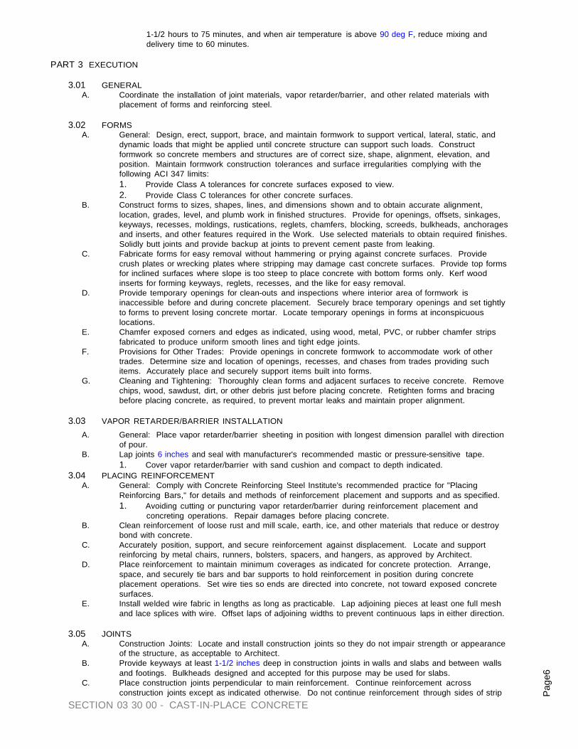
SECTION 03 30 00 - CAST-IN-PLACE CONCRETE
Page
6
1-1/2 hours to 75 minutes, and when air temperature is above 90 deg F, reduce mixing and delivery time to 60 minutes.
PART 3 EXECUTION
3.01 GENERAL
A. Coordinate the installation of joint materials, vapor retarder/barrier, and other related materials with placement of forms and reinforcing steel.
3.02 FORMS
A. General: Design, erect, support, brace, and maintain formwork to support vertical, lateral, static, and dynamic loads that might be applied until concrete structure can support such loads. Construct formwork so concrete members and structures are of correct size, shape, alignment, elevation, and position. Maintain formwork construction tolerances and surface irregularities complying with the following ACI 347 limits: 1. Provide Class A tolerances for concrete surfaces exposed to view. 2. Provide Class C tolerances for other concrete surfaces.
B. Construct forms to sizes, shapes, lines, and dimensions shown and to obtain accurate alignment, location, grades, level, and plumb work in finished structures. Provide for openings, offsets, sinkages, keyways, recesses, moldings, rustications, reglets, chamfers, blocking, screeds, bulkheads, anchorages and inserts, and other features required in the Work. Use selected materials to obtain required finishes. Solidly butt joints and provide backup at joints to prevent cement paste from leaking.
C. Fabricate forms for easy removal without hammering or prying against concrete surfaces. Provide crush plates or wrecking plates where stripping may damage cast concrete surfaces. Provide top forms for inclined surfaces where slope is too steep to place concrete with bottom forms only. Kerf wood inserts for forming keyways, reglets, recesses, and the like for easy removal.
D. Provide temporary openings for clean-outs and inspections where interior area of formwork is inaccessible before and during concrete placement. Securely brace temporary openings and set tightly to forms to prevent losing concrete mortar. Locate temporary openings in forms at inconspicuous locations.
E. Chamfer exposed corners and edges as indicated, using wood, metal, PVC, or rubber chamfer strips fabricated to produce uniform smooth lines and tight edge joints.
F. Provisions for Other Trades: Provide openings in concrete formwork to accommodate work of other trades. Determine size and location of openings, recesses, and chases from trades providing such items. Accurately place and securely support items built into forms.
G. Cleaning and Tightening: Thoroughly clean forms and adjacent surfaces to receive concrete. Remove chips, wood, sawdust, dirt, or other debris just before placing concrete. Retighten forms and bracing before placing concrete, as required, to prevent mortar leaks and maintain proper alignment.
3.03 VAPOR RETARDER/BARRIER INSTALLATION
A. General: Place vapor retarder/barrier sheeting in position with longest dimension parallel with direction of pour.
B. Lap joints 6 inches and seal with manufacturer's recommended mastic or pressure-sensitive tape. 1. Cover vapor retarder/barrier with sand cushion and compact to depth indicated.
3.04 PLACING REINFORCEMENT A. General: Comply with Concrete Reinforcing Steel Institute's recommended practice for "Placing
Reinforcing Bars," for details and methods of reinforcement placement and supports and as specified. 1. Avoiding cutting or puncturing vapor retarder/barrier during reinforcement placement and
concreting operations. Repair damages before placing concrete. B. Clean reinforcement of loose rust and mill scale, earth, ice, and other materials that reduce or destroy
bond with concrete. C. Accurately position, support, and secure reinforcement against displacement. Locate and support
reinforcing by metal chairs, runners, bolsters, spacers, and hangers, as approved by Architect. D. Place reinforcement to maintain minimum coverages as indicated for concrete protection. Arrange,
space, and securely tie bars and bar supports to hold reinforcement in position during concrete placement operations. Set wire ties so ends are directed into concrete, not toward exposed concrete surfaces.
E. Install welded wire fabric in lengths as long as practicable. Lap adjoining pieces at least one full mesh and lace splices with wire. Offset laps of adjoining widths to prevent continuous laps in either direction.
3.05 JOINTS
A. Construction Joints: Locate and install construction joints so they do not impair strength or appearance of the structure, as acceptable to Architect.
B. Provide keyways at least 1-1/2 inches deep in construction joints in walls and slabs and between walls and footings. Bulkheads designed and accepted for this purpose may be used for slabs.
C. Place construction joints perpendicular to main reinforcement. Continue reinforcement across construction joints except as indicated otherwise. Do not continue reinforcement through sides of strip
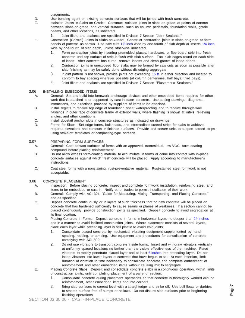
SECTION 03 30 00 - CAST-IN-PLACE CONCRETE
Page
7
placements. D. Use bonding agent on existing concrete surfaces that will be joined with fresh concrete. E. Isolation Joints in Slabs-on-Grade: Construct isolation joints in slabs-on-grade at points of contact
between slabs-on-grade and vertical surfaces, such as column pedestals, foundation walls, grade beams, and other locations, as indicated. 1. Joint fillers and sealants are specified in Division 7 Section "Joint Sealants."
F. Contraction (Control) Joints in Slabs-on-Grade: Construct contraction joints in slabs-on-grade to form panels of patterns as shown. Use saw cuts 1/8 inch wide by one-fourth of slab depth or inserts 1/4 inch wide by one-fourth of slab depth, unless otherwise indicated. 1. Form contraction joints by inserting premolded plastic, hardboard, or fiberboard strip into fresh
concrete until top surface of strip is flush with slab surface. Tool slab edges round on each side of insert. After concrete has cured, remove inserts and clean groove of loose debris.
2. Contraction joints in unexposed floor slabs may be formed by saw cuts as soon as possible after slab finishing as may be safely done without dislodging aggregate.
3. If joint pattern is not shown, provide joints not exceeding 15 ft. in either direction and located to conform to bay spacing wherever possible (at column centerlines, half bays, third bays).
4. Joint fillers and sealants are specified in Division 7 Section "Elastomeric Sealants." 3.06 INSTALLING EMBEDDED ITEMS
A. General: Set and build into formwork anchorage devices and other embedded items required for other work that is attached to or supported by cast-in-place concrete. Use setting drawings, diagrams, instructions, and directions provided by suppliers of items to be attached.
B. Install reglets to receive top edge of foundation sheet waterproofing and to receive through-wall flashings in outer face of concrete frame at exterior walls, where flashing is shown at lintels, relieving angles, and other conditions.
C. Install dovetail anchor slots in concrete structures as indicated on drawings. D. Forms for Slabs: Set edge forms, bulkheads, and intermediate screed strips for slabs to achieve
required elevations and contours in finished surfaces. Provide and secure units to support screed strips using strike-off templates or compacting-type screeds.
3.07 PREPARING FORM SURFACES
A. General: Coat contact surfaces of forms with an approved, nonresidual, low-VOC, form-coating compound before placing reinforcement.
B. Do not allow excess form-coating material to accumulate in forms or come into contact with in-place concrete surfaces against which fresh concrete will be placed. Apply according to manufacturer's instructions.
C. Coat steel forms with a nonstaining, rust-preventative material. Rust-stained steel formwork is not acceptable.
3.08 CONCRETE PLACEMENT
A. Inspection: Before placing concrete, inspect and complete formwork installation, reinforcing steel, and items to be embedded or cast in. Notify other trades to permit installation of their work.
B. General: Comply with ACI 304, "Guide for Measuring, Mixing, Transporting, and Placing Concrete," and as specified.
C. Deposit concrete continuously or in layers of such thickness that no new concrete will be placed on concrete that has hardened sufficiently to cause seams or planes of weakness. If a section cannot be placed continuously, provide construction joints as specified. Deposit concrete to avoid segregation at its final location.
D. Placing Concrete in Forms: Deposit concrete in forms in horizontal layers no deeper than 24 inches and in a manner to avoid inclined construction joints. Where placement consists of several layers, place each layer while preceding layer is still plastic to avoid cold joints. 1. Consolidate placed concrete by mechanical vibrating equipment supplemented by hand-
spading, rodding, or tamping. Use equipment and procedures for consolidation of concrete complying with ACI 309.
2. Do not use vibrators to transport concrete inside forms. Insert and withdraw vibrators vertically at uniformly spaced locations no farther than the visible effectiveness of the machine. Place vibrators to rapidly penetrate placed layer and at least 6 inches into preceding layer. Do not insert vibrators into lower layers of concrete that have begun to set. At each insertion, limit duration of vibration to time necessary to consolidate concrete and complete embedment of reinforcement and other embedded items without causing mix to segregate.
E. Placing Concrete Slabs: Deposit and consolidate concrete slabs in a continuous operation, within limits of construction joints, until completing placement of a panel or section. 1. Consolidate concrete during placement operations so that concrete is thoroughly worked around
reinforcement, other embedded items and into corners. 2. Bring slab surfaces to correct level with a straightedge and strike off. Use bull floats or darbies
to smooth surface free of humps or hollows. Do not disturb slab surfaces prior to beginning finishing operations.
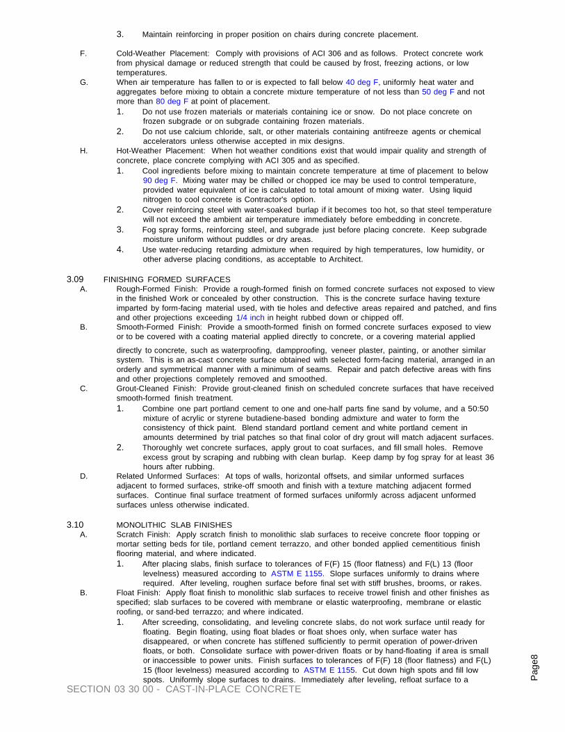
SECTION 03 30 00 - CAST-IN-PLACE CONCRETE
Page
8
3. Maintain reinforcing in proper position on chairs during concrete placement.
F. Cold-Weather Placement: Comply with provisions of ACI 306 and as follows. Protect concrete work from physical damage or reduced strength that could be caused by frost, freezing actions, or low temperatures.
G. When air temperature has fallen to or is expected to fall below 40 deg F, uniformly heat water and aggregates before mixing to obtain a concrete mixture temperature of not less than 50 deg F and not more than 80 deg F at point of placement. 1. Do not use frozen materials or materials containing ice or snow. Do not place concrete on
frozen subgrade or on subgrade containing frozen materials. 2. Do not use calcium chloride, salt, or other materials containing antifreeze agents or chemical
accelerators unless otherwise accepted in mix designs. H. Hot-Weather Placement: When hot weather conditions exist that would impair quality and strength of
concrete, place concrete complying with ACI 305 and as specified. 1. Cool ingredients before mixing to maintain concrete temperature at time of placement to below
90 deg F. Mixing water may be chilled or chopped ice may be used to control temperature, provided water equivalent of ice is calculated to total amount of mixing water. Using liquid nitrogen to cool concrete is Contractor's option.
2. Cover reinforcing steel with water-soaked burlap if it becomes too hot, so that steel temperature will not exceed the ambient air temperature immediately before embedding in concrete.
3. Fog spray forms, reinforcing steel, and subgrade just before placing concrete. Keep subgrade moisture uniform without puddles or dry areas.
4. Use water-reducing retarding admixture when required by high temperatures, low humidity, or other adverse placing conditions, as acceptable to Architect.
3.09 FINISHING FORMED SURFACES
A. Rough-Formed Finish: Provide a rough-formed finish on formed concrete surfaces not exposed to view in the finished Work or concealed by other construction. This is the concrete surface having texture imparted by form-facing material used, with tie holes and defective areas repaired and patched, and fins and other projections exceeding 1/4 inch in height rubbed down or chipped off.
B. Smooth-Formed Finish: Provide a smooth-formed finish on formed concrete surfaces exposed to view or to be covered with a coating material applied directly to concrete, or a covering material applied
directly to concrete, such as waterproofing, dampproofing, veneer plaster, painting, or another similar system. This is an as-cast concrete surface obtained with selected form-facing material, arranged in an orderly and symmetrical manner with a minimum of seams. Repair and patch defective areas with fins and other projections completely removed and smoothed.
C. Grout-Cleaned Finish: Provide grout-cleaned finish on scheduled concrete surfaces that have received smooth-formed finish treatment. 1. Combine one part portland cement to one and one-half parts fine sand by volume, and a 50:50
mixture of acrylic or styrene butadiene-based bonding admixture and water to form the consistency of thick paint. Blend standard portland cement and white portland cement in amounts determined by trial patches so that final color of dry grout will match adjacent surfaces.
2. Thoroughly wet concrete surfaces, apply grout to coat surfaces, and fill small holes. Remove excess grout by scraping and rubbing with clean burlap. Keep damp by fog spray for at least 36 hours after rubbing.
D. Related Unformed Surfaces: At tops of walls, horizontal offsets, and similar unformed surfaces adjacent to formed surfaces, strike-off smooth and finish with a texture matching adjacent formed surfaces. Continue final surface treatment of formed surfaces uniformly across adjacent unformed surfaces unless otherwise indicated.
3.10 MONOLITHIC SLAB FINISHES
A. Scratch Finish: Apply scratch finish to monolithic slab surfaces to receive concrete floor topping or mortar setting beds for tile, portland cement terrazzo, and other bonded applied cementitious finish flooring material, and where indicated. 1. After placing slabs, finish surface to tolerances of F(F) 15 (floor flatness) and F(L) 13 (floor
levelness) measured according to ASTM E 1155. Slope surfaces uniformly to drains where required. After leveling, roughen surface before final set with stiff brushes, brooms, or rakes.
B. Float Finish: Apply float finish to monolithic slab surfaces to receive trowel finish and other finishes as specified; slab surfaces to be covered with membrane or elastic waterproofing, membrane or elastic roofing, or sand-bed terrazzo; and where indicated. 1. After screeding, consolidating, and leveling concrete slabs, do not work surface until ready for
floating. Begin floating, using float blades or float shoes only, when surface water has disappeared, or when concrete has stiffened sufficiently to permit operation of power-driven floats, or both. Consolidate surface with power-driven floats or by hand-floating if area is small or inaccessible to power units. Finish surfaces to tolerances of F(F) 18 (floor flatness) and F(L) 15 (floor levelness) measured according to ASTM E 1155. Cut down high spots and fill low spots. Uniformly slope surfaces to drains. Immediately after leveling, refloat surface to a

SECTION 03 30 00 - CAST-IN-PLACE CONCRETE
Page
9
uniform, smooth, granular texture. C. Trowel Finish: Apply a trowel finish to monolithic slab surfaces exposed to view and slab surfaces to be
covered with resilient flooring, carpet, ceramic or quarry tile, paint, or another thin film-finish coating system. 1. After floating, begin first trowel-finish operation using a power-driven trowel. Begin final
troweling when surface produces a ringing sound as trowel is moved over surface. Consolidate concrete surface by final hand-troweling operation, free of trowel marks, uniform in texture and appearance, and finish surfaces to tolerances of F(F) 20 (floor flatness) and F(L) 17 (floor levelness) measured according to ASTM E 1155. Grind smooth any surface defects that would telegraph through applied floor covering system.
D. Trowel and Fine Broom Finish: Where ceramic or quarry tile is to be installed with thin-set mortar, apply a trowel finish as specified, then immediately follow by slightly scarifying the surface with a fine broom.
E. Nonslip Broom Finish: Apply a nonslip broom finish to exterior concrete platforms, steps, and ramps, and elsewhere as indicated. 1. Immediately after float finishing, slightly roughen concrete surface by brooming with fiber-bristle
broom perpendicular to main traffic route. Coordinate required final finish with Architect before application.
3.11 MISCELLANEOUS CONCRETE ITEMS
A. Filling In: Fill in holes and openings left in concrete structures for passage of work by other trades, unless otherwise shown or directed, after work of other trades is in place. Mix, place, and cure concrete as specified to blend with in-place construction. Provide other miscellaneous concrete filling shown or required to complete Work.
B. Curbs: Provide monolithic finish to interior curbs by stripping forms while concrete is still green and by steel-troweling surfaces to a hard, dense finish with corners, intersections, and terminations slightly rounded.
C. Equipment Bases and Foundations: Provide machine and equipment bases and foundations as shown on drawings. Set anchor bolts for machines and equipment to template at correct elevations, complying with diagrams or templates of manufacturer furnishing machines and equipment.
3.12 CONCRETE CURING AND PROTECTION
A. General: Protect freshly placed concrete from premature drying and excessive cold or hot temperatures. In hot, dry, and windy weather protect concrete from rapid moisture loss before and during finishing operations with an evaporation-control material. Apply according to manufacturer's instructions after screeding and bull floating, but before power floating and troweling.
B. Start initial curing as soon as free water has disappeared from concrete surface after placing and finishing. Weather permitting, keep continuously moist for not less than 7 days.
C. Curing Methods: Cure concrete by curing compound, by moist curing, by moisture-retaining cover curing, or by combining these methods, as specified.
D. Provide moisture curing by the following methods:
1. Keep concrete surface continuously wet by covering with water. 2. Use continuous water-fog spray. 3. Cover concrete surface with specified absorptive cover, thoroughly saturate cover with water,
and keep continuously wet. Place absorptive cover to provide coverage of concrete surfaces and edges, with a 4 inch lap over adjacent absorptive covers.
E. Provide moisture-retaining cover curing as follows: 1. Cover concrete surfaces with moisture-retaining cover for curing concrete, placed in widest
practicable width with sides and ends lapped at least 3 inches and sealed by waterproof tape or adhesive. Immediately repair any holes or tears during curing period using cover material and waterproof tape.
F. Apply curing compound on exposed interior slabs and on exterior slabs, walks, and curbs as follows:
1. Apply curing compound to concrete slabs as soon as final finishing operations are complete (within 2 hours and after surface water sheen has disappeared). Apply uniformly in continuous operation by power spray or roller according to manufacturer's directions. Recoat areas subjected to heavy rainfall within 3 hours after initial application. Maintain continuity of coating and repair damage during curing period.
2. Use membrane curing compounds that will not affect surfaces to be covered with finish materials applied directly to concrete.
G. Curing Formed Surfaces: Cure formed concrete surfaces, including underside of beams, supported slabs, and other similar surfaces, by moist curing with forms in place for the full curing period or until forms are removed. If forms are removed, continue curing by methods specified above, as applicable.
H. Curing Unformed Surfaces: Cure unformed surfaces, including slabs, floor topping, and other flat surfaces, by applying the appropriate curing method. 1. Final cure concrete surfaces to receive finish flooring with a moisture-retaining cover, unless
otherwise directed.

SECTION 03 30 00 - CAST-IN-PLACE CONCRETE
Page
10
3.13 REMOVING FORMS
A. General: Formwork not supporting weight of concrete, such as sides of beams, walls, columns, and similar parts of the work, may be removed after cumulatively curing at not less than 50 deg F for 24 hours after placing concrete, provided concrete is sufficiently hard to not be damaged by form-removal operations, and provided curing and protection operations are maintained.
B. Formwork supporting weight of concrete, such as beam soffits, joists, slabs, and other structural elements, may not be removed in less than 14 days or until concrete has attained at least 75 percent of design minimum compressive strength at 28 days. Determine potential compressive strength of in- place concrete by testing field-cured specimens representative of concrete location or members.
C. Form-facing material may be removed 4 days after placement only if shores and other vertical supports have been arranged to permit removal of form-facing material without loosening or disturbing shores and supports.
3.14 REUSING FORMS
A. Clean and repair surfaces of forms to be reused in the Work. Split, frayed, delaminated, or otherwise damaged form-facing material will not be acceptable for exposed surfaces. Apply new form-coating compound as specified for new formwork.
B. When forms are extended for successive concrete placement, thoroughly clean surfaces, remove fins and laitance, and tighten forms to close joints. Align and secure joint to avoid offsets. Do not use patched forms for exposed concrete surfaces except as acceptable to Architect.
3.15 CONCRETE SURFACE REPAIRS A. Patching Defective Areas: Repair and patch defective areas with cement mortar immediately after
removing forms, when acceptable to Architect.
B. Mix dry-pack mortar, consisting of one part portland cement to 2-1/2 parts fine aggregate passing a No. 16 mesh sieve, using only enough water as required for handling and placing. 1. Cut out honeycombs, rock pockets, voids over 1/4 inch in any dimension, and holes left by tie
rods and bolts down to solid concrete but in no case to a depth less than 1 inch. Make edges of cuts perpendicular to the concrete surface. Thoroughly clean, dampen with water, and brush- coat the area to be patched with bonding agent. Place patching mortar before bonding agent has dried.
2. For surfaces exposed to view, blend white portland cement and standard portland cement so that, when dry, patching mortar will match surrounding color. Provide test areas at inconspicuous locations to verify mixture and color match before proceeding with patching. Compact mortar in place and strike-off slightly higher than surrounding surface.
C. Repairing Formed Surfaces: Remove and replace concrete having defective surfaces if defects cannot be repaired to satisfaction of Architect. Surface defects include color and texture irregularities, cracks, spalls, air bubbles, honeycomb, rock pockets, fins and other projections on the surface, and stains and other discolorations that cannot be removed by cleaning. Flush out form tie holes and fill with dry-pack mortar or precast cement cone plugs secured in place with bonding agent. 1. Repair concealed formed surfaces, where possible, containing defects that affect the concrete's
durability. If defects cannot be repaired, remove and replace the concrete. D. Repairing Unformed Surfaces: Test unformed surfaces, such as monolithic slabs, for smoothness and
verify surface tolerances specified for each surface and finish. Correct low and high areas as specified. Test unformed surfaces sloped to drain for trueness of slope and smoothness by using a template having the required slope. 1. Repair finished unformed surfaces containing defects that affect the concrete's durability.
Surface defects include crazing and cracks in excess of 0.01 inch wide or that penetrate to the reinforcement or completely through nonreinforced sections regardless of width, spalling, popouts, honeycombs, rock pockets, and other objectionable conditions.
2. Correct high areas in unformed surfaces by grinding after concrete has cured at least 14 days. 3. Correct low areas in unformed surfaces during or immediately after completing surface finishing
operations by cutting out low areas and replacing with patching mortar. Finish repaired areas to blend into adjacent concrete. Proprietary underlayment compounds may be used when acceptable to Architect.
4. Repair defective areas, except random cracks and single holes not exceeding 1 inch in diameter, by cutting out and replacing with fresh concrete. Remove defective areas with clean, square cuts and expose reinforcing steel with at least 3/4 inch clearance all around. Dampen concrete surfaces in contact with patching concrete and apply bonding agent. Mix patching concrete of same materials to provide concrete of same type or class as original concrete. Place, compact, and finish to blend with adjacent finished concrete. Cure in same manner as adjacent concrete.
E. Perform structural repairs with prior approval of Architect for method and procedure, using specified epoxy adhesive and mortar.
F. Repair methods not specified above may be used, subject to acceptance of Architect.

SECTION 03 30 00 - CAST-IN-PLACE CONCRETE
Page
11
3.16 QUALITY CONTROL TESTING DURING CONSTRUCTION A. Labratory tests for concrete materials and mix design will be performed in accordance with Section 01
45 00 Quality Control, Testing Laboratory Services. B. Sampling and testing for quality control during concrete placement may include the following, as
directed by Architect. 1. Sampling Fresh Concrete: ASTM C 172, except modified for slump to comply with ASTM C 94.
a. Slump: ASTM C 143; one test at point of discharge for each day's pour of each type of concrete; additional tests when concrete consistency seems to have changed.
b. Air Content: ASTM C 173, volumetric method for lightweight or normal weight concrete; ASTM C 231, pressure method for normal weight concrete; one for each day's pour of each type of air-entrained concrete.
c. Concrete Temperature: ASTM C 1064; one test hourly when air temperature is 40 deg F and below, when 80 deg F and above, and one test for each set of compressive-strength specimens.
d. Compression Test Specimen: ASTM C 31; one set of four standard cylinders for each compressive-strength test, unless otherwise directed. Mold and store cylinders for laboratory-cured test specimens except when field-cured test specimens are required.
e. Compressive-Strength Tests: ASTM C 39; one set for each day's pour exceeding 5 cu. yd. plus additional sets for each 50 cu. yd. more than the first 25 cu. yd. of each concrete class placed in any one day; one specimen tested at 7 days, two specimens tested at 28 days, and one specimen retained in reserve for later testing if required.
2. When frequency of testing will provide fewer than five strength tests for a given class of concrete, conduct testing from at least five randomly selected batches or from each batch if fewer than five are used.
3. When total quantity of a given class of concrete is less than 50 cu. yd., Architect may waive strength testing if adequate evidence of satisfactory strength is provided.
4. When strength of field-cured cylinders is less than 85 percent of companion laboratory-cured cylinders, evaluate current operations and provide corrective procedures for protecting and curing the in-place concrete.
5. Strength level of concrete will be considered satisfactory if averages of sets of three consecutive strength test results equal or exceed specified compressive strength and no individual strength test result falls below specified compressive strength by more than 500 psi.
C. Test results will be reported in writing to Architect, Structural Engineer, ready-mix producer, and Contractor within 24 hours after tests. Reports of compressive strength tests shall contain the Project identification name and number, date of concrete placement, name of concrete testing service, concrete type and class, location of concrete batch in structure, design compressive strength at 28 days, concrete mix proportions and materials, compressive breaking strength, and type of break for both 7- day tests and 28-day tests.
D. Nondestructive Testing: Impact hammer, sonoscope, or other nondestructive device may be permitted but shall not be used as the sole basis for acceptance or rejection.
E. Additional Tests: The testing agency will make additional tests of in-place concrete when test results indicate specified concrete strengths and other characteristics have not been attained in the structure, as directed by Architect. Testing agency may conduct tests to determine adequacy of concrete by cored cylinders complying with ASTM C 42, or by other methods as directed.
END OF SECTION 03 30 00

SECTION 03 54 13 GYPSUM CEMENT UNDERLAYMENT + SECTION 09 80 00 ACOUSTIC TREATMENT 1
SECTION 03 54 13 GYPSUM CEMENT UNDERLAYMENT
+ SECTION 09 80 00 ACOUSTIC TREATMENT
PART 1 GENERAL 1.01 SUMMARY
A. Description of Work: Work of this section includes underlayment for interior finish flooring and is not limited to, the following: 1. Maxxon Gyp-Crete 2000/3.2K Floor Underlayment covering normal project conditions and applications. 2. Division 3 Section Concrete: “Cast Underlayment” and “Gypsum Cement Underlayment” 3. Division 9 Section Finishes: “Acoustic Treatment”
1.02 REFERENCES
A. Underwriters Laboratory Fire Resistance Volume 1 www.ul.com B. ASTM E336 and E1007 Field Sound Transmission Class (F-STC), Field
Impact Insulation Class (F-IIC) C. ASTM E90 and E492 Sound Transmission Class (STC), Impact
Insulation Class (IIC) D. GREENGUARD Certified Air Quality Sciences GREENGUARD Indoor Air
Quality Certified www.greenguard.org E. ASTM C472M Compressive strength of gypsum concrete F. ASTM F2170 Standard Test Method for Determining Relative
Humidity in Concrete Floor Slab G. ASTM F2419 Standard Test Method for Installation of Thick
Poured Gypsum Concrete and Preparation of Surface to Receive Resilient Flooring
H. ASTM F2678 Standard Practice for Preparing Panel Underlayments, Thick Poured Gypsum Concrete Underlayments, Thick Poured Lightweight Cellular Concrete Underlayments, and Concrete Subfloors with Underlayment Patching Compounds to Receive Resilient Flooring
I. TCNA F 180 Tile Council of North America Installation Handbook www.tileusa.com
J. NWFA National Wood Flooring Association Instructions www.nwfa.org
K. Maxxon Corporation Maxxon Procedures for Attaching Finished Floor Goods to Maxxon Underlayments www.maxxon.com
1.03 SUBMITTALS A. Product Data: Submit Gyp-Crete 2000/3.2K sales sheet, Ultimate Sound Control Systems, Procedures for Attaching
Finished Floor Goods to Maxxon Underlayments, and Maxxon’s Building Conditions Guide with project materials clearly identified for each required product or system.
B. UL Directory Fire Resistance Volume 1 - Architect to utilize one or more of the following:
Rating Underwriters Laboratory File Number
1 Hr Fire Rating L546, L555, L558, L562, L563, L574, L579, L585, L592
Example: UL L546
C. Acoustical Data: Submit sound tests according to IBC code criteria ASTM E492 (IIC) and ASTM E90 (STC) or ASTM E1007 (F-IIC) and E336 (F-IIC).
D. Code Approvals: See www.maxxon.com for the current list of code approvals.
1.04 SYSTEM REQUIREMENTS A. Performance Requirements:
1. Gyp-Crete 2000/3.2K Floor Underlayment (Always a “Green” building material) i) Compressive strength 2000 to 3200 psi (14MPa to 22 MPa) ii) Density 115 pounds per cubic foot (1,840 kg/m3)
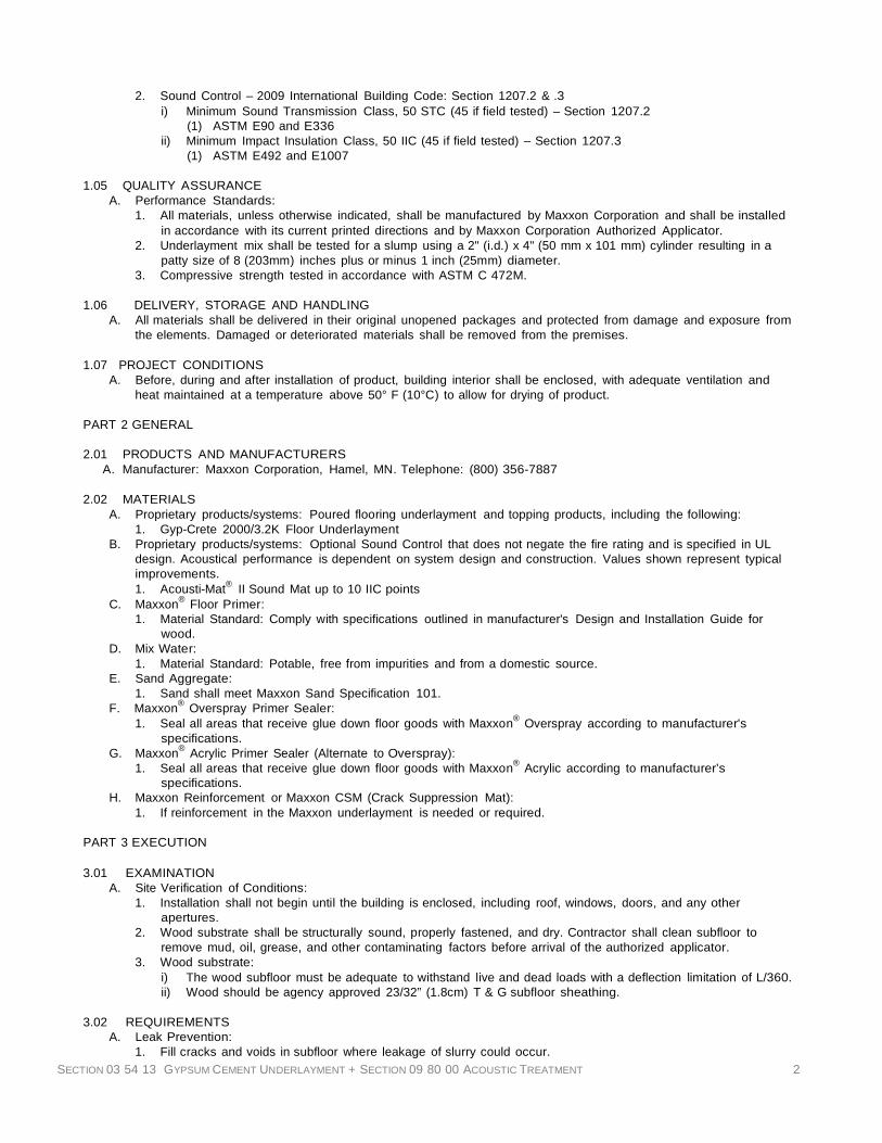
SECTION 03 54 13 GYPSUM CEMENT UNDERLAYMENT + SECTION 09 80 00 ACOUSTIC TREATMENT 2
2. Sound Control – 2009 International Building Code: Section 1207.2 & .3 i) Minimum Sound Transmission Class, 50 STC (45 if field tested) – Section 1207.2
(1) ASTM E90 and E336 ii) Minimum Impact Insulation Class, 50 IIC (45 if field tested) – Section 1207.3
(1) ASTM E492 and E1007
1.05 QUALITY ASSURANCE A. Performance Standards:
1. All materials, unless otherwise indicated, shall be manufactured by Maxxon Corporation and shall be installed in accordance with its current printed directions and by Maxxon Corporation Authorized Applicator.
2. Underlayment mix shall be tested for a slump using a 2" (i.d.) x 4" (50 mm x 101 mm) cylinder resulting in a patty size of 8 (203mm) inches plus or minus 1 inch (25mm) diameter.
3. Compressive strength tested in accordance with ASTM C 472M.
1.06 DELIVERY, STORAGE AND HANDLING A. All materials shall be delivered in their original unopened packages and protected from damage and exposure from
the elements. Damaged or deteriorated materials shall be removed from the premises.
1.07 PROJECT CONDITIONS A. Before, during and after installation of product, building interior shall be enclosed, with adequate ventilation and
heat maintained at a temperature above 50° F (10°C) to allow for drying of product.
PART 2 GENERAL
2.01 PRODUCTS AND MANUFACTURERS A. Manufacturer: Maxxon Corporation, Hamel, MN. Telephone: (800) 356-7887
2.02 MATERIALS
A. Proprietary products/systems: Poured flooring underlayment and topping products, including the following: 1. Gyp-Crete 2000/3.2K Floor Underlayment
B. Proprietary products/systems: Optional Sound Control that does not negate the fire rating and is specified in UL design. Acoustical performance is dependent on system design and construction. Values shown represent typical improvements. 1. Acousti-Mat® II Sound Mat up to 10 IIC points
C. Maxxon® Floor Primer: 1. Material Standard: Comply with specifications outlined in manufacturer's Design and Installation Guide for
wood. D. Mix Water:
1. Material Standard: Potable, free from impurities and from a domestic source. E. Sand Aggregate:
1. Sand shall meet Maxxon Sand Specification 101. F. Maxxon® Overspray Primer Sealer:
1. Seal all areas that receive glue down floor goods with Maxxon® Overspray according to manufacturer's specifications.
G. Maxxon® Acrylic Primer Sealer (Alternate to Overspray): 1. Seal all areas that receive glue down floor goods with Maxxon® Acrylic according to manufacturer’s
specifications. H. Maxxon Reinforcement or Maxxon CSM (Crack Suppression Mat):
1. If reinforcement in the Maxxon underlayment is needed or required.
PART 3 EXECUTION
3.01 EXAMINATION A. Site Verification of Conditions:
1. Installation shall not begin until the building is enclosed, including roof, windows, doors, and any other apertures.
2. Wood substrate shall be structurally sound, properly fastened, and dry. Contractor shall clean subfloor to remove mud, oil, grease, and other contaminating factors before arrival of the authorized applicator.
3. Wood substrate: i) The wood subfloor must be adequate to withstand live and dead loads with a deflection limitation of L/360. ii) Wood should be agency approved 23/32” (1.8cm) T & G subfloor sheathing.
3.02 REQUIREMENTS
A. Leak Prevention: 1. Fill cracks and voids in subfloor where leakage of slurry could occur.
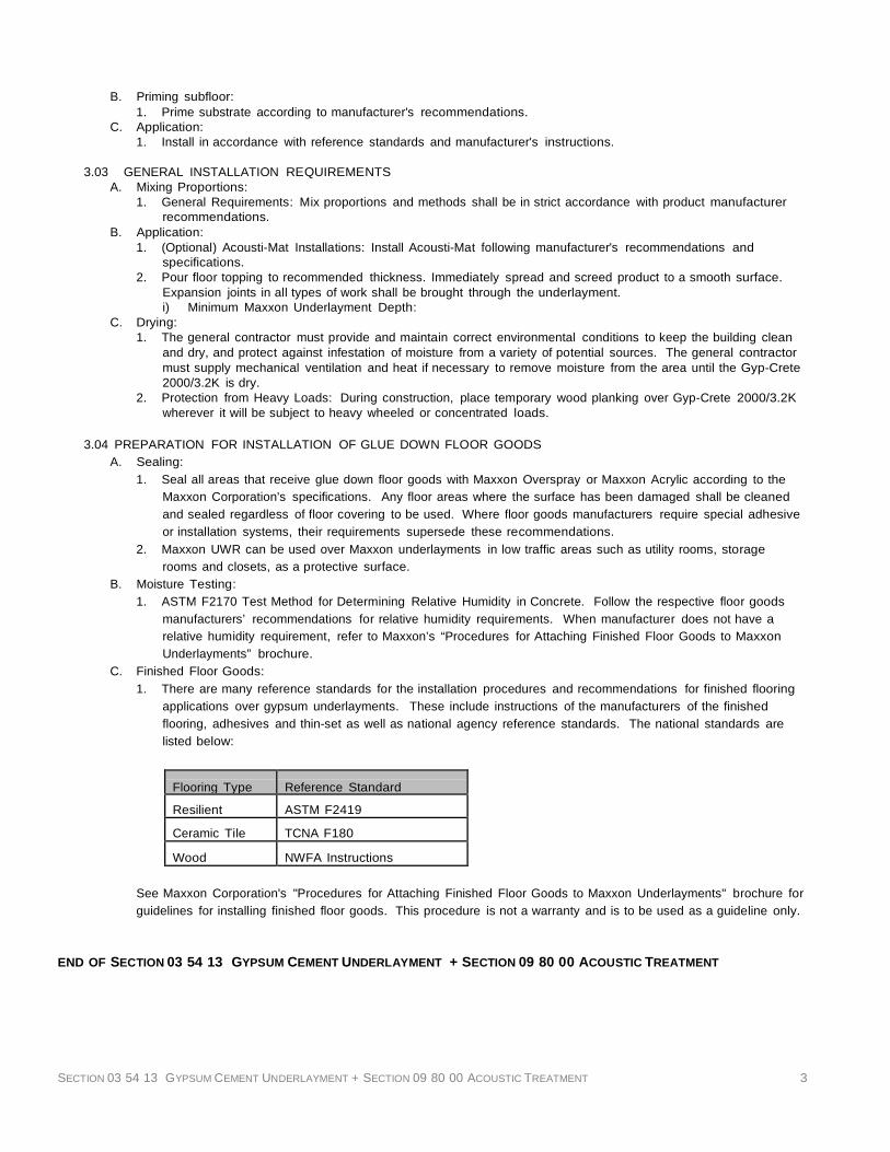
SECTION 03 54 13 GYPSUM CEMENT UNDERLAYMENT + SECTION 09 80 00 ACOUSTIC TREATMENT 3
B. Priming subfloor: 1. Prime substrate according to manufacturer's recommendations.
C. Application: 1. Install in accordance with reference standards and manufacturer's instructions.
3.03 GENERAL INSTALLATION REQUIREMENTS
A. Mixing Proportions: 1. General Requirements: Mix proportions and methods shall be in strict accordance with product manufacturer
recommendations. B. Application:
1. (Optional) Acousti-Mat Installations: Install Acousti-Mat following manufacturer's recommendations and specifications.
2. Pour floor topping to recommended thickness. Immediately spread and screed product to a smooth surface. Expansion joints in all types of work shall be brought through the underlayment. i) Minimum Maxxon Underlayment Depth:
C. Drying: 1. The general contractor must provide and maintain correct environmental conditions to keep the building clean
and dry, and protect against infestation of moisture from a variety of potential sources. The general contractor must supply mechanical ventilation and heat if necessary to remove moisture from the area until the Gyp-Crete 2000/3.2K is dry.
2. Protection from Heavy Loads: During construction, place temporary wood planking over Gyp-Crete 2000/3.2K wherever it will be subject to heavy wheeled or concentrated loads.
3.04 PREPARATION FOR INSTALLATION OF GLUE DOWN FLOOR GOODS
A. Sealing: 1. Seal all areas that receive glue down floor goods with Maxxon Overspray or Maxxon Acrylic according to the
Maxxon Corporation's specifications. Any floor areas where the surface has been damaged shall be cleaned and sealed regardless of floor covering to be used. Where floor goods manufacturers require special adhesive or installation systems, their requirements supersede these recommendations.
2. Maxxon UWR can be used over Maxxon underlayments in low traffic areas such as utility rooms, storage rooms and closets, as a protective surface.
B. Moisture Testing: 1. ASTM F2170 Test Method for Determining Relative Humidity in Concrete. Follow the respective floor goods
manufacturers’ recommendations for relative humidity requirements. When manufacturer does not have a relative humidity requirement, refer to Maxxon’s “Procedures for Attaching Finished Floor Goods to Maxxon Underlayments” brochure.
C. Finished Floor Goods: 1. There are many reference standards for the installation procedures and recommendations for finished flooring
applications over gypsum underlayments. These include instructions of the manufacturers of the finished flooring, adhesives and thin-set as well as national agency reference standards. The national standards are listed below:
Flooring Type
Reference Standard
Resilient
ASTM F2419
Ceramic Tile
TCNA F180
Wood
NWFA Instructions
See Maxxon Corporation's "Procedures for Attaching Finished Floor Goods to Maxxon Underlayments" brochure for guidelines for installing finished floor goods. This procedure is not a warranty and is to be used as a guideline only.
END OF SECTION 03 54 13 GYPSUM CEMENT UNDERLAYMENT + SECTION 09 80 00 ACOUSTIC TREATMENT

SECTION 05 12 00 - STRUCTURAL STEEL 1
SECTION 05 12 00 - STRUCTURAL STEEL
PART 1 - GENERAL
1.1 SUMMARY
A. This Section includes structural steel and grout.
1.2 PERFORMANCE REQUIREMENTS
A. Connections: Provide details of simple shear connections required by the Contract Documents to be selected or completed by structural-steel fabricator to withstand loads indicated and comply with other information and restrictions indicated.
1. Select and complete connections using schematic details indicated and AISC's "Manual of Steel
Construction.
1.3 SUBMITTALS
A. Product Data: For each type of product indicated.
B. Shop Drawings: Show fabrication of structural-steel components.
C. Welding certificates.
D. Mill test reports.
E. Source quality-control test reports.
1.4 QUALITY ASSURANCE
A. Fabricator Qualifications: A qualified fabricator who participates in the AISC Quality Certification Program and is designated an AISC-Certified Plant, Category Sbd.
B. Welding: Qualify procedures and personnel according to AWS D1.1, "Structural Welding Code--Steel."
C. Comply with applicable provisions of AISC's "Code of Standard Practice for Steel Buildings and Bridges."
D. Preinstallation Conference: Conduct conference at Architect’s Office.
PART 2 - PRODUCTS
2.1 STRUCTURAL-STEEL MATERIALS
A. W-Shapes: ASTM A 992/A 992M or ASTM A 572/A 572M, Grade 50.
B. Channels, Angles, M, S-Shapes: ASTM A 36, or ASTM A 572, A 572M, Grade 50.
C. Plate and Bar: ASTM A 36 or ASTM A 572, Grade 50.
D. Cold-Formed Hollow Structural Sections: ASTM A 500, Grade B, structural tubing.
E. Steel Pipe: ASTM A 53/A 53M, Type E or S, Grade B.
F. Welding Electrodes: Comply with AWS requirements.
2.2 BOLTS, CONNECTORS, AND ANCHORS
A. High-Strength Bolts, Nuts, and Washers: ASTM A 325, Type 1, heavy hex steel structural bolts; ASTM A 563 heavy hex carbon-steel nuts; and ASTM F 436 hardened carbon-steel washers.
1. Finish: Plain.
2. Direct-Tension Indicators: ASTM F 959, Type 325 compressible-washer type.
a. Finish: Plain.
B. Shear Connectors: ASTM A 108, Grades 1015 through 1020, headed-stud type, cold-finished carbon steel; AWS D1.1, Type B.
C. Unheaded Anchor Rods: ASTM F 1554, Grade 36.
1. Configuration: Straight or Hooked as indicated.
2. Finish: Plain.
D. Headed Anchor Rods: ASTM F 1554, Grade 36.
1. Finish: Plain.
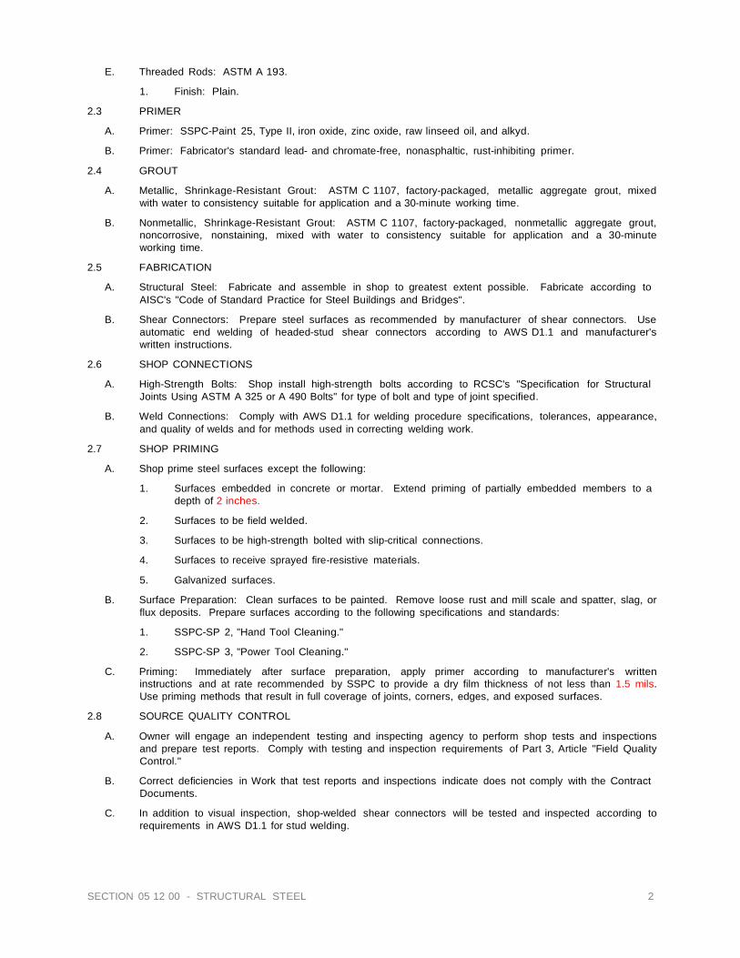
SECTION 05 12 00 - STRUCTURAL STEEL 2
E. Threaded Rods: ASTM A 193.
1. Finish: Plain.
2.3 PRIMER
A. Primer: SSPC-Paint 25, Type II, iron oxide, zinc oxide, raw linseed oil, and alkyd.
B. Primer: Fabricator's standard lead- and chromate-free, nonasphaltic, rust-inhibiting primer.
2.4 GROUT
A. Metallic, Shrinkage-Resistant Grout: ASTM C 1107, factory-packaged, metallic aggregate grout, mixed with water to consistency suitable for application and a 30-minute working time.
B. Nonmetallic, Shrinkage-Resistant Grout: ASTM C 1107, factory-packaged, nonmetallic aggregate grout,
noncorrosive, nonstaining, mixed with water to consistency suitable for application and a 30-minute working time.
2.5 FABRICATION
A. Structural Steel: Fabricate and assemble in shop to greatest extent possible. Fabricate according to
AISC's "Code of Standard Practice for Steel Buildings and Bridges".
B. Shear Connectors: Prepare steel surfaces as recommended by manufacturer of shear connectors. Use automatic end welding of headed-stud shear connectors according to AWS D1.1 and manufacturer's written instructions.
2.6 SHOP CONNECTIONS
A. High-Strength Bolts: Shop install high-strength bolts according to RCSC's "Specification for Structural
Joints Using ASTM A 325 or A 490 Bolts" for type of bolt and type of joint specified.
B. Weld Connections: Comply with AWS D1.1 for welding procedure specifications, tolerances, appearance, and quality of welds and for methods used in correcting welding work.
2.7 SHOP PRIMING
A. Shop prime steel surfaces except the following:
1. Surfaces embedded in concrete or mortar. Extend priming of partially embedded members to a depth of 2 inches.
2. Surfaces to be field welded.
3. Surfaces to be high-strength bolted with slip-critical connections.
4. Surfaces to receive sprayed fire-resistive materials.
5. Galvanized surfaces.
B. Surface Preparation: Clean surfaces to be painted. Remove loose rust and mill scale and spatter, slag, or
flux deposits. Prepare surfaces according to the following specifications and standards:
1. SSPC-SP 2, "Hand Tool Cleaning."
2. SSPC-SP 3, "Power Tool Cleaning."
C. Priming: Immediately after surface preparation, apply primer according to manufacturer's written instructions and at rate recommended by SSPC to provide a dry film thickness of not less than 1.5 mils. Use priming methods that result in full coverage of joints, corners, edges, and exposed surfaces.
2.8 SOURCE QUALITY CONTROL
A. Owner will engage an independent testing and inspecting agency to perform shop tests and inspections
and prepare test reports. Comply with testing and inspection requirements of Part 3, Article "Field Quality Control."
B. Correct deficiencies in Work that test reports and inspections indicate does not comply with the Contract
Documents.
C. In addition to visual inspection, shop-welded shear connectors will be tested and inspected according to requirements in AWS D1.1 for stud welding.
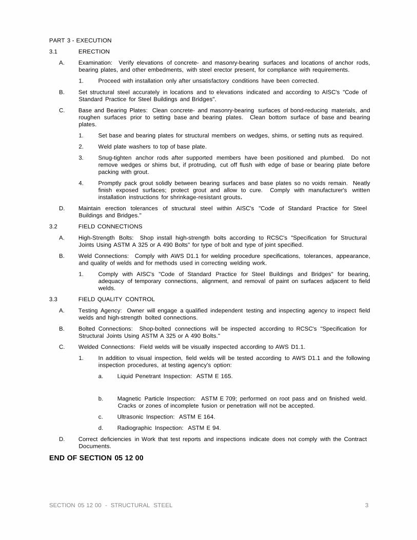
SECTION 05 12 00 - STRUCTURAL STEEL 3
PART 3 - EXECUTION
3.1 ERECTION
A. Examination: Verify elevations of concrete- and masonry-bearing surfaces and locations of anchor rods, bearing plates, and other embedments, with steel erector present, for compliance with requirements.
1. Proceed with installation only after unsatisfactory conditions have been corrected.
B. Set structural steel accurately in locations and to elevations indicated and according to AISC's "Code of
Standard Practice for Steel Buildings and Bridges".
C. Base and Bearing Plates: Clean concrete- and masonry-bearing surfaces of bond-reducing materials, and roughen surfaces prior to setting base and bearing plates. Clean bottom surface of base and bearing plates.
1. Set base and bearing plates for structural members on wedges, shims, or setting nuts as required.
2. Weld plate washers to top of base plate.
3. Snug-tighten anchor rods after supported members have been positioned and plumbed. Do not
remove wedges or shims but, if protruding, cut off flush with edge of base or bearing plate before packing with grout.
4. Promptly pack grout solidly between bearing surfaces and base plates so no voids remain. Neatly finish exposed surfaces; protect grout and allow to cure. Comply with manufacturer's written installation instructions for shrinkage-resistant grouts.
D. Maintain erection tolerances of structural steel within AISC's "Code of Standard Practice for Steel
Buildings and Bridges."
3.2 FIELD CONNECTIONS
A. High-Strength Bolts: Shop install high-strength bolts according to RCSC's "Specification for Structural Joints Using ASTM A 325 or A 490 Bolts" for type of bolt and type of joint specified.
B. Weld Connections: Comply with AWS D1.1 for welding procedure specifications, tolerances, appearance,
and quality of welds and for methods used in correcting welding work.
1. Comply with AISC's "Code of Standard Practice for Steel Buildings and Bridges" for bearing, adequacy of temporary connections, alignment, and removal of paint on surfaces adjacent to field welds.
3.3 FIELD QUALITY CONTROL
A. Testing Agency: Owner will engage a qualified independent testing and inspecting agency to inspect field
welds and high-strength bolted connections.
B. Bolted Connections: Shop-bolted connections will be inspected according to RCSC's "Specification for Structural Joints Using ASTM A 325 or A 490 Bolts."
C. Welded Connections: Field welds will be visually inspected according to AWS D1.1.
1. In addition to visual inspection, field welds will be tested according to AWS D1.1 and the following
inspection procedures, at testing agency's option:
a. Liquid Penetrant Inspection: ASTM E 165.
b. Magnetic Particle Inspection: ASTM E 709; performed on root pass and on finished weld. Cracks or zones of incomplete fusion or penetration will not be accepted.
c. Ultrasonic Inspection: ASTM E 164.
d. Radiographic Inspection: ASTM E 94.
D. Correct deficiencies in Work that test reports and inspections indicate does not comply with the Contract Documents.
END OF SECTION 05 12 00

SECTION 05 30 00 - STEEL DECK 1
SECTION 05 30 00 - STEEL DECK
PART 1 - GENERAL
1.1 SUMMARY
A. This Section includes the following:
1. Roof Deck.
2. Floor Deck
1.2 SUBMITTALS
A. Product Data: For each type of deck, accessory, and product indicated.
B. Shop Drawings: Include layout and types of deck panels, anchorage details, reinforcing channels, pans, deck openings, special jointing, accessories, and attachments to other construction.
C. Product certificates.
D. Welding certificates.
E. Research/evaluation reports.
1.3 QUALITY ASSURANCE
A. Welding: Qualify procedures and personnel according to AWS D1.1, "Structural Welding Code--Steel," and AWS D1.3, "Structural Welding Code--Sheet Steel."
B. Fire-Test-Response Characteristics: Where indicated, provide steel deck units identical to those steel
deck units tested for fire resistance per ASTM E 119 by a testing and inspection agency acceptable to authorities having jurisdiction.
1. Fire-Resistance Ratings: Indicated by design designations from UL's "Fire Resistance Directory" or
from the listings of another testing and inspecting agency.
2. Steel deck units shall be identified with appropriate markings of applicable testing and inspecting agency.
C. AISI Specifications: Calculate structural characteristics of steel deck according to AISI's "Specification for
the Design of Cold-Formed Steel Structural Members."
PART 2 - PRODUCTS
2.1 MANUFACTURERS
A. Available Manufacturers: Subject to compliance with requirements, manufacturers offering products that may be incorporated into the Work include, but are not limited to, the following:
B. Manufacturers: Subject to compliance with requirements, provide products by one of the following:
1. BHP Steel Building Products USA Inc.
2. Consolidated Systems, Inc.
3. Epic Metals Corp.
4. Marilyn Steel Products, Inc.
5. Nucor Corp.; Vulcraft Div.
6. Roof Deck, Inc.
7. United Steel Deck, Inc.
8. Verco Manufacturing Co.
9. Wheeling Corrugating Co.; Div. of Wheeling-Pittsburgh Steel Corp.
2.2 ROOF DECK
A. Steel Roof Deck: Fabricate panels, without top-flange stiffening grooves, to comply with "SDI Specifications and Commentary for Steel Roof Deck," in SDI Publication No. 29.
1. Painted Steel Sheet: ASTM A 653 Structural Steel, Grade 33,

SECTION 05 30 00 - STEEL DECK 2
2. Deck Profile: Type 1.5 B and Type 3 N.
3. Profile Depth: 1-1/2 inches, type B, 3 inches Type N.
4. Design Uncoated-Steel Thickness: 0.0295 inches - 22 gage, both types.
2.3 ACCESSORIES
A. Accessories: Steel deck manufacturer's standard accessory materials, including mechanical fasteners, closure strips, pour stops, and closures for deck.
B. Shear Connectors: ASTM A 108, Grades 1010 through 1020 headed stud type, cold-finished carbon steel,
AWS D1.1, Type B, with arc shields.
C. Galvanizing Repair Paint: ASTM A 780, SSPC-Paint 20 or DOD-P-21035, with dry film containing a minimum of 94 percent zinc dust by weight.
D. Repair Paint: Lead- and chromate-free rust-inhibitive primer.
PART 3 - EXECUTION
3.1 INSTALLATION
A. Install deck panels and accessories according to applicable specifications and commentary in SDI Publication No. 29, manufacturer's written instructions, and requirements in this Section.
B. Place deck panels on supporting frame and adjust to final position with ends accurately aligned and
bearing on supporting frame before being permanently fastened. Do not stretch or contract side-lap interlocks.
C. Place deck panels flat and square and fasten to supporting frame without warp or deflection.
D. Cut and neatly fit deck panels and accessories around openings and other work projecting through or
adjacent to decking.
E. Provide additional reinforcement and closure pieces at openings as required for strength, continuity of decking, and support of other work.
F. Comply with AWS requirements and procedures for manual shielded metal arc welding, appearance and
quality of welds, and methods used for correcting welding work.
1. Mechanical fasteners may NOT be used in lieu of welding to fasten deck. Locate mechanical fasteners at side laps and install according to deck manufacturer's written instructions.
G. Roof Deck Accessories: Install sump pans, ridge and valley plates, finish strips, cover plates, end
closures, and reinforcing channels according to deck manufacturer's written instructions. Weld to substrate to provide a complete deck installation.
H. Shear Connectors: Weld shear connectors through deck to supporting frame according to AWS D1.1 and
manufacturer's written instructions. Butt end joints of deck panels; do not overlap. Remove and discard arc shields after welding shear connectors.
I. Pour Stops and Girder Fillers: Weld steel sheet pour stops and girder fillers to supporting structure according to SDI recommendations, unless otherwise indicated.
J. Repairs and Protection:
1. Galvanizing Repairs: Prepare and repair damaged galvanized coatings on both surfaces of deck
with galvanized repair paint according to ASTM A 780 and manufacturer's written instructions.
3.2 FIELD QUALITY CONTROL
A. Testing: Engage a qualified independent testing agency to perform field quality-control testing.
B. Field welds will be subject to inspection.
C. Shear connector stud welds will be tested and inspected according to AWS D1.1.
D. Remove and replace work that does not comply with specified requirements.
E. Additional testing and inspecting, at Contractor's expense, will be performed to determine compliance of corrected work with specified requirements.
END OF SECTION 05 30 00

05 50 00 - METAL FABRICATIONS/ 1
SECTION 05 50 00 - METAL FABRICATIONS
A. PART 1 GENERAL 1. RELATED DOCUMENTS
A) Provisions established within the General and Supplementary General Conditions of the Contract, Division 1 - General Requirements, and the Drawings are collectively applicable to this Section.
2. REFERENCES A) Standard of the Following as Referenced
(1) American Institute of Steel Construction (AISC) (2) American Society for Testing and Materials (ASTM) (3) American Welding Society (AWS) (4) American Iron and Steel Institute (AISI) (5) Steel Structures Painting Council (SSPC)
B) Industry Standards (1) AISC: Specifications for the Design, Fabrication, and Erection of Structural Steel for Buildings, 1980
edition with supplements (2) AWS: (3) AWS D1.1-85: Structural Welding Code (4) AWS D2.1-84: Welding Procedure and Performance Qualification (5) SSPC: Systems and Specifications, 1982 edition
3. SYSTEM DESCRIPTION A) Design Requirements
(1) Provide approved shop drawings for stairs and rails. (2) Guardrail vertical and horizontal forces: 50 lbs per lineal foot or 200 pounds at any point applied from
any direction, and as per current IBC code requirements. 4. SUBMITTALS
A) Shop Drawings (1) Indicate sizes, shapes, fabrication, and installation details for fabricated metal (2) Show anchorage and accessory items. Furnish templates and setting diagrams for required anchor
installation. 5. QUALITY ASSURANCE
A) Welder's Certifications (1) Employ welders currently qualified under AWS standard qualification procedures to perform type of
required Work. (2)Require any welder to retake qualification test, when, in opinion of Owner's Representative, Work of
welder creates reasonable doubt as to proficiency of welder. Conduct retests at no additional expense to Owner. Submit recertification to Owner's Representative after welder has passed retest.
(3) Assign each shop and field welder an identifying symbol or mark: identify all welds made by him. 6. PROJECT CONDITIONS
A) Field Measurements (1) Take field measurements prior to preparation of shop drawings and fabrication, where possible, to
ensure fitting of Work, however, do not delay job progress. (2) Allow for trimming and fitting wherever taking of field measurements before fabrication might delay
Work.
B. PART 2 PRODUCTS 1. MATERIALS
A) General (1) Provide materials free from defects impairing strength, durability, or appearance; have structural
properties to sustain or withstand strains and stressed to which subjected. (2) Exposed surfaces throughout Project: Same inherent texture and color for like locations. (3) Fastenings: Non-corrosive, non-staining, and concealed, except as indicated on reviewed shop
drawings. (4) Exposed fastenings: Same materials, color, and finish as material to which applied: countersunk and
finished flush. (5) Grind exposed welds smooth to form neat uniform fillet without weakening base metal. Remove slag
from unexposed welds before applying shop coating. (6) Form molded, bent, or shaped members with clean, sharp arises, without dents, scratches, cracks,
and other defects. (7) Provide anchors, bolts, shims, and accessory items for building into and fastening to adjacent Work.
B) Structural Materials (1) Structural steel shapes: Meeting ASTM A36-84a. (2) Hot-roller carbon steel sheets and strips: Meeting ASTM A568-84 and A570-84a, Grade (3) Cold-rolled carbon steel sheets: Meeting ASTM A366-72 (1979).

05 50 00 - METAL FABRICATIONS/ 2
(4) Steel tube: Cold formed welded structural steel tubing meeting A500, Grade B. (5) Other steel: Mild steel. (6) Handrail wall brackets: Malleable cast iron with not less then 3" projection from finish wall surface to
center pipe handrail: wall plate portion drilled to receive one 3/8" diameter bolt. (7) Bolts, Nuts and Washers: ASTM A307. (8) Welding Materials: AWS D1.1; type required for materials being welded. (9) Primer: FS TT-P-86G, Type I or II for shop application and field touch-up. Verify compatibility of
selected product with intended surface finish prior to application. (10) Exposed Mechanical Fastenings: Screws or bolts; unobtrusively located; consistent with design of
structure. B) Primer Paint
(1) Provide compatible with required finish coats of paint: coordinate metal primer selection with finish paint requirements specified in Painting section.
(2) Type: Red iron oxide or zinc chromate primer meeting SSPC-Paint 11-82. 2. FABRICATION
A) Shop Assembly (1) General
(a) Form Work true to line and level with accurate angles and surfaces and straight sharp edges. Ease exposed edges to radius of approximately 1/32". Form bent metal corners to smallest radius possible without causing grain separation or otherwise impairing Work.
(b) Weld corners and seams continuously and in accord with AWS recommendations. Grind exposed welds smooth and flush: match and blend with adjoining surfaces.
(c) Provide for anchorage of type indicated on reviewed shop drawings coordinated with supporting structure. Fabricate and space anchoring devices to provide adequate support.
(d) Remove scale, rust, and other deleterious materials before applying shop primer. (e) Preassemble items in shop to greatest extent possible to minimize field splicing and assembly of
units at Project site. Disassemble units only to extent necessary for shipping and handling limitations. Mark units for reassembly and coordinated installation.
(2) Metal Stairs (a) Verify dimensions on site prior to shop fabrication. (b) Fabricate items with joints tightly fitted and secured. (c) Fit and ship assemble sections in largest practical sizes, for handling through building openings. (d) Grind exposed welds flush and smooth with adjacent finished surface. Ease exposed edges to
small uniform radius. (e) Make exposed joints butt tight, flush and hairline. (f) Accurately form components required for anchorage of stairs and landings to each other and to
building structure. (g) Fabricate stairs with pre-cast concrete treads. (h) Secure treads to stringers with bolt angles. (i) Form stringers of rolled steel channels, depth as indicated. (j) Prime paint all steel components. (k) See structural drawings for other requirements
(3) Steel Railings: Sizes and locations per plans. (a) Provide square steel handrails and guardrail where indicated, consisting of top and intermediate
rails, posts, and bracket mounted handrails at walls. Provide 1 1/2" square nominal size rails, unless otherwise indicated as per IBC code. Sheathing: 2x2” WWF.
(b) Join posts and rails at corners by mitered and welded joints made by fitting post to top rail and intermediate rail to posts: miter corners, groove weld joints, and grind smooth. Butt railing splices and reinforce rails by tight fitting interior sleeve not less than 6" long.
(c) Steel railings will be joined at corners. (d) Bar railings: Per Plans. (e) Exterior: Provide prime painting railing assemblies.
(4) Miscellaneous construction: In addition to items specified in this section, provide items indicated or required to complete Work, including, but not limited to the following: (a) Lintels, shelf angles, and anchors:
(i) Exterior: Prime coated steel (ii) Interior: Prime coated steel
(b) 6" by 0.25" wall thickness, steel pipe bollards, concrete filled, unless otherwise indicated. (c) Hanger rods not provided by other trades. Provide in size and length indicated or required:
threaded full length or at ends only as required: hot dip galvanize exterior items, prime coat interior items, unless otherwise indicated.
(d) Tube columns and shapes, connectors, flitch plates, steel channel door frames, and other miscellaneous items.

05 50 00 - METAL FABRICATIONS/ 3
B) Shop Finishing (1) Ferrous metals, not galvanized:
(a) Clean all surfaces after fabrication and immediately prior to shop painting in accord with SSPCC- SP2, Hand Tool Cleaning: SSPC-SP3, Power Tool Cleaning: or SSPC-SP7, Brush-off Blast Cleaning, at manufacturer's option.
(b) Apply specified shop coat in accord with SSPC-PA1-82 and manufacturer's product data to provide 2.0 mils DFT, minimum. Apply shop coat of paint within four hours after cleaning and before rust-bloom occurs. Paint only in relative humidity below 85% and surface temperature 5 F above dew point, minimum.
(c) Coat anchors built into masonry with asphalt paint unless galvanized. Leave metal Work encased in concrete unpainted, unless specified otherwise.
(d) Do not shop paint metal where hot-dip galvanized or zinc coated metal is specified or indicated. (2) Galvanized metals:
(a) Comply with ASTM A123-84 for hot-dip galvanized coatings applied on products fabricated from roller, pressed, or forged steel shapes, plates, bars, and strips or zinc coatings on assembled steel products.
(b) Coating weight: Designated in ASTM A123-84, Table I for class and thickness of material coated. Chemically treat galvanized surfaces where shop coat of paint is specified to produce paint bond.
(c) Galvanize after fabrication, except for nuts and bolts. (3) Aluminum: Coat all aluminum in contact with concrete with zinc chromate or bitumastic.
C) Allowable Tolerances (1) Machine field and shop assemble mechanical joints to fit within +1/32". (2) Sizes of each element of an assembly: Correct within 1/8": total size of free standing assembly,
correct within 1/2".
C. PART 3 EXECUTION 1. PREPARATION
A) Inserts and anchorages: Furnish inserts and anchoring devices to be set in concrete for installation of Work. B) Coordinate setting drawings, diagrams, templates, instructions, and directions for installation of anchorages,
such as concrete inserts, anchor bolts, and miscellaneous items having integral anchors embedded in concrete construction.
2. INSTALLATION A) General:
(1) Fastening to in-place construction: Provide anchorage devices and fasteners where necessary for securing items to in-place construction: include threaded fasteners for concrete inserts, toggle bolts, and through-bolts.
(2) Cutting, fitting, and placement: Perform cutting, drilling, and fitting required for installation of Work. Set Work in location, alignment, and elevation, plum, level, true, and free of rack: measure from established lines and levels. Install Work in accord with reviewed shop drawings, local codes and ordinances.
(3) Fit exposed connections together to form tight hairline joints. Field weld connections which cannot be shop welded because of shipping size limitations. Grind joints smooth: touch-up shop primer coat with same type primer.
(4) Allowable tolerances: Install free standing items to +1/4" of proper position or per local codes and ordinances, whichever is more stringent.
B) Met al Stairs: (1) Verify that field conditions are acceptable and are ready to receive work. (2) Beginning of installation means erector accepts existing conditions. (3) Clean and strip primed steel items to bare metal where site welding is required. (4) Supply items required to be cast into concrete with setting templates, to appropriate sections. (5) Erect stairs level and plumb, free from distortion or defects detrimental to appearance or performance. (6) Provide anchors, plates, angles, hangers, and struts required for connecting stairs to structure. (7) Verify alignment with adjacent construction. Coordinate related work. (8) Do not field cut or alter members. (9) Field bolt and weld to match standard of shop bolting and welding. Hide bolts and screws whenever possible. (10) Mechanically fasten joints butted tight, flush, and hairline. Grind welds smooth and flush. (11) Obtain Architect / Engineer and Owner's Representative's approval prior to site cutting or making adjustments not scheduled. (12) After erection, prime welds, abrasions, and surfaces not shop primed. (13) Verify stairways are in compliance with OSHA prior to stair utilization.
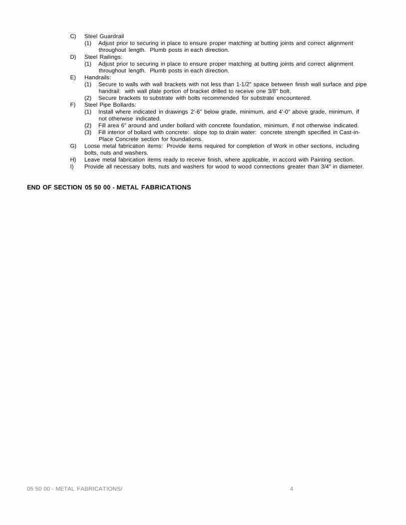
05 50 00 - METAL FABRICATIONS/ 4
C) Steel Guardrail (1) Adjust prior to securing in place to ensure proper matching at butting joints and correct alignment
throughout length. Plumb posts in each direction. D) Steel Railings:
(1) Adjust prior to securing in place to ensure proper matching at butting joints and correct alignment throughout length. Plumb posts in each direction.
E) Handrails: (1) Secure to walls with wall brackets with not less than 1-1/2" space between finish wall surface and pipe
handrail: with wall plate portion of bracket drilled to receive one 3/8" bolt. (2) Secure brackets to substrate with bolts recommended for substrate encountered.
F) Steel Pipe Bollards: (1) Install where indicated in drawings 2'-6" below grade, minimum, and 4'-0" above grade, minimum, if
not otherwise indicated. (2) Fill area 6" around and under bollard with concrete foundation, minimum, if not otherwise indicated. (3) Fill interior of bollard with concrete: slope top to drain water: concrete strength specified in Cast-in-
Place Concrete section for foundations. G) Loose metal fabrication items: Provide items required for completion of Work in other sections, including
bolts, nuts and washers. H) Leave metal fabrication items ready to receive finish, where applicable, in accord with Painting section. I) Provide all necessary bolts, nuts and washers for wood to wood connections greater than 3/4" in diameter.
END OF SECTION 05 50 00 - METAL FABRICATIONS
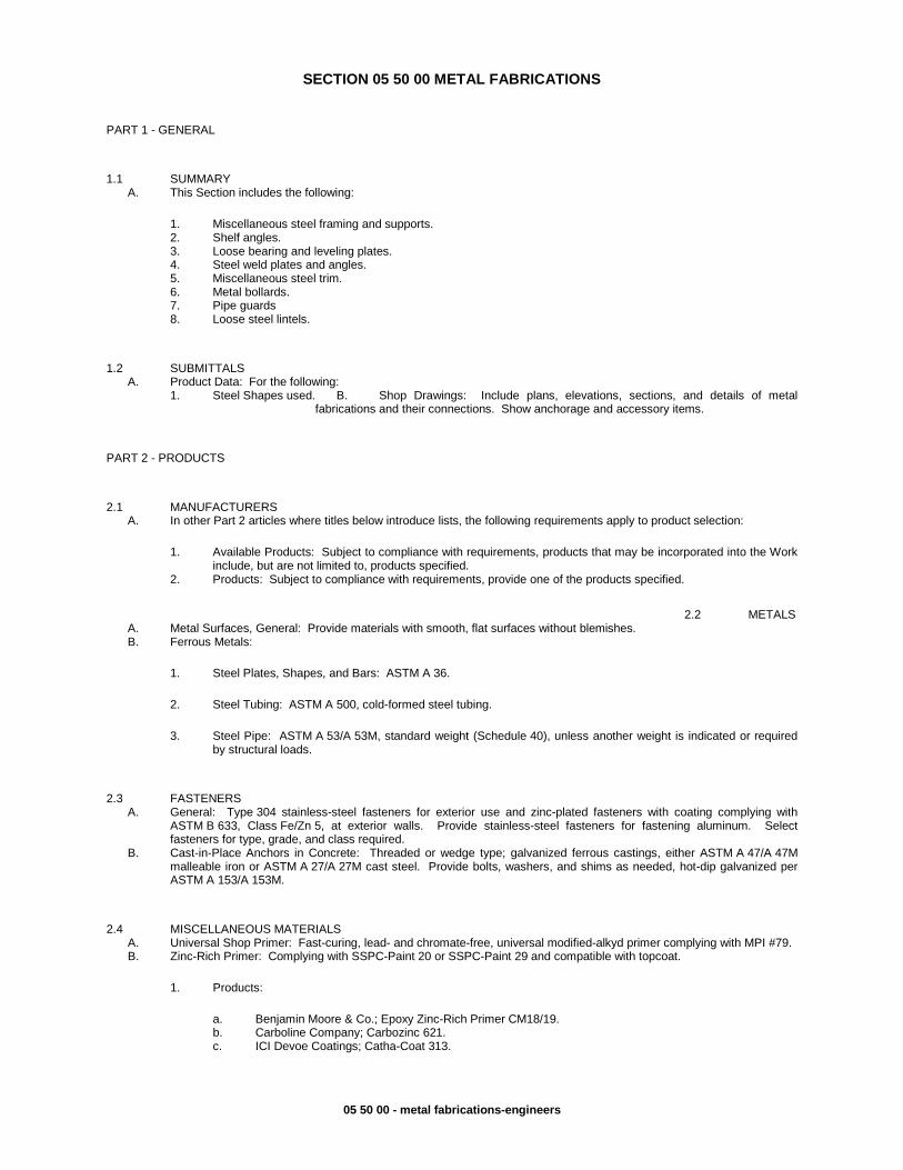
05 50 00 - metal fabrications-engineers
SECTION 05 50 00 METAL FABRICATIONS
PART 1 - GENERAL
1.1 SUMMARY A. This Section includes the following:
1. Miscellaneous steel framing and supports.
1.2 SUBMITTALS A. Product Data: For the following:
B. Shop Drawings: Include plans, elevations, sections, and details of metal fabrications and their connections. Show anchorage and accessory items.
PART 2 - PRODUCTS
2.1 MANUFACTURERS A. In other Part 2 articles where titles below introduce lists, the following requirements apply to product selection:
1. Available Products: Subject to compliance with requirements, products that may be incorporated into the Work include, but are not limited to, products specified.
2.2 METALS A. Metal Surfaces, General: Provide materials with smooth, flat surfaces without blemishes. B. Ferrous Metals:
1. Steel Plates, Shapes, and Bars: ASTM A 36.
2. Steel Tubing: ASTM A 500, cold-formed steel tubing.
2.3 FASTENERS A. General: Type 304 stainless-steel fasteners for exterior use and zinc-plated fasteners with coating complying with
ASTM B 633, Class Fe/Zn 5, at exterior walls. Provide stainless-steel fasteners for fastening aluminum. Select fasteners for type, grade, and class required.
B. Cast-in-Place Anchors in Concrete: Threaded or wedge type; galvanized ferrous castings, either ASTM A 47/A 47M malleable iron or ASTM A 27/A 27M cast steel. Provide bolts, washers, and shims as needed, hot-dip galvanized per ASTM A 153/A 153M.
2.4 MISCELLANEOUS MATERIALS A. Universal Shop Primer: Fast-curing, lead- and chromate-free, universal modified-alkyd primer complying with MPI #79. B. Zinc-Rich Primer: Complying with SSPC-Paint 20 or SSPC-Paint 29 and compatible with topcoat.
1. Products:
a. Benjamin Moore & Co.; Epoxy Zinc-Rich Primer CM18/19. b. Carboline Company; Carbozinc 621. c. ICI Devoe Coatings; Catha-Coat 313.
2. Shelf angles. 3. Loose bearing and leveling plates. 4. Steel weld plates and angles. 5. Miscellaneous steel trim. 6. Metal bollards. 7. Pipe guards 8. Loose steel lintels.
1. Steel Shapes used.
2. Products: Subject to compliance with requirements, provide one of the products specified.
3. Steel Pipe: ASTM A 53/A 53M, standard weight (Schedule 40), unless another weight is indicated or required by structural loads.

05 50 00 - metal fabrications-engineers
d. International Coatings Limited; Interzinc 315 Epoxy Zinc-Rich Primer. e. PPG Architectural Finishes, Inc.; Aquapon Zinc-Rich Primer 97-670. f. Sherwin-Williams Company (The); Corothane I GalvaPac Zinc Primer. g. Tnemec Company, Inc.; Tneme-Zinc 90-97.
C. Galvanizing Repair Paint: SSPC-Paint 20, high-zinc-dust-content paint for regalvanizing welds in steel. D. Nonshrink, Nonmetallic Grout: Factory-packaged, nonstaining, noncorrosive, nongaseous grout complying with
ASTM C 1107. E. Concrete Materials and Properties: Comply with requirements in Division 03 30 00 "Cast-in-Place Concrete" for normal-
weight, air-entrained, ready-mix concrete with a minimum 28-day compressive strength of 3000 psi, unless otherwise indicated.
2.5 FABRICATION A. General: Preassemble items in the shop to greatest extent possible. Use connections that maintain structural value of
joined pieces.
1. Cut, drill, and punch metals cleanly and accurately. Remove burrs and ease edges. Remove sharp or rough areas on exposed surfaces.
B. Miscellaneous Framing and Supports: Provide steel framing and supports not specified in other Sections as needed to complete the Work. Fabricate units from steel shapes, plates, and bars of welded construction. Cut, drill, and tap units to receive hardware, hangers, and similar items.
C. Loose Steel Lintels: Fabricate loose steel lintels from steel angles and shapes of size indicated for openings and recesses in masonry walls and partitions at locations indicated.
1. Lintels in Exterior Walls: Prime with zinc-rich primer. D. Shelf Angles: Fabricate shelf angles of sizes indicated and for attachment to framing. Fabricate with horizontally
slotted holes to receive 3/4-inch bolts, spaced not more than 6 inches from ends and 24 inches o.c.
1. Shelf Angles in Exterior Walls: Prime with zinc-rich primer.
E. Loose Bearing and Leveling Plates: Provide loose bearing and leveling plates for steel items bearing on masonry or concrete construction. Drill plates to receive anchor bolts.
F. Miscellaneous Steel Trim: Fabricate units from steel shapes, plates, and bars of profiles shown with continuously welded joints and smooth exposed edges. Miter corners and use concealed field splices where possible. Provide cutouts, fittings, and anchorages as needed to coordinate assembly and installation with other work.
1. Exterior Miscellaneous Steel Trim: Prime with zinc-rich primer. G. Metal Ladders: Comply with ANSI A14.3, unless otherwise indicated.
1. Elevator Pit Ladders: Comply with ASME A17.1. 2. Space siderails 18 inches apart, unless otherwise indicated. 3. Steel Ladder Construction: Flat bar siderails, with ¾-inch-diameter steel bar rungs fitted in centerline of
siderails, plug-welded, and ground smooth on outer rail faces. Provide nonslip surfaces on top of each rung. 4. Fabricate ladder safety cages to comply with ANSI A14.3. Fabricate from same metal as ladders to which
safety cages are attached and assemble by welding or riveting.
H. Metal Bollards: Fabricate from Schedule 40 steel pipe.
1. Cap bollards with ¼-inch-thick steel plate. 2. Fabricate bollards with 3/8-inch-thick steel baseplates for bolting to concrete slab. Drill baseplates at all four
corners for ¾-inch-anchor bolts. 3. Fabricate sleeves for bollard anchorage from steel pipe with ¼-inch-thick steel plate welded to bottom of sleeve.
I. Pipe Guards: Fabricate from 3/8-inch-thick by 12-inch-wide steel plate, bent to fit flat against the wall or column at both ends and to fit around pipe with 2-inch clearance between pipe and pipe guard. Drill each end for two 3/4 –inch anchor bolts.
2.6 FINISHES A. Comply with NAAMM's "Metal Finishes Manual for Architectural and Metal Products" for recommendations for applying
and designating finishes. Finish metal fabrications after assembly.
2. Weld corners and seams continuously. Use materials and methods that minimize distortion and develop strength and corrosion resistance of base metals. Obtain fusion without undercut or overlap. Remove welding flux immediately. Finish exposed welds smooth and blended.
3. Form exposed connections with hairline joints, flush and smooth, using concealed fasteners where possible. Locate joints where least conspicuous.
4. Fabricate seams and other connections that will be exposed to weather in a manner to exclude water. Provide weep holes where water may accumulate.
5. Where units are indicated to be cast into concrete or built into masonry, equip with integrally welded steel strap anchors, not less than 24 inches o.c.
2. Furnish wedge-type concrete inserts, complete with fasteners, to attach shelf angles to cast-in-place concrete.

05 50 00 - metal fabrications-engineers
B. Steel and Iron Finishes:
a. Exteriors SSPC Zone 1B and Items Indicated to Receive Zinc-Rich Primer: SSPC-SP 6/NACE No. 3, "Commercial Blast Cleaning."
b. Interiors SSPC Zone 1A: SSPC-SP 3, "Power Tool Cleaning."
2. Shop Priming: Apply shop primer to uncoated surfaces of metal fabrications, except those with galvanized finishes and those to be embedded in concrete, sprayed-on fireproofing, or masonry, to comply with SSPC-PA 1, "Paint Application Specification No. 1: Shop, Field, and Maintenance Painting," for shop painting.
PART 3 - EXECUTION
3.1 INSTALLATION A. General: Perform cutting, drilling, and fitting required for installing metal fabrications. Set metal fabrications accurately
in location, with edges and surfaces level, plumb, and true.
1. Fit exposed connections accurately together. Weld connections that are not to be left as exposed joints but cannot be shop welded. Do not weld, cut, or abrade surfaces of exterior units that have been hot-dip galvanized after fabrication.
B. Set bearing and leveling plates on cleaned surfaces using wedges, shims, or leveling nuts. After bearing members have been positioned and plumbed, tighten anchor bolts and pack solidly with nonshrink, nonmetallic grout.
C. Bollards:
1. Anchor bollards to existing construction with expansion anchors. Provide four ¾-inch bolts at each bollard. 2. Anchor bollards in concrete with pipe sleeves preset and anchored into concrete. Fill annular space around
bollard solidly with nonshrink, nonmetallic grout. 3. Anchor bollards in place with concrete footings. Place concrete and vibrate or tamp for consolidation. Support
and brace bollards in position until concrete has cured. 4. Fill bollards solidly with concrete, mounding top surface to shed water.
D. Touch up surfaces and finishes after erection.
1. Painted Surfaces: Clean field welds, bolted connections, and abraded areas and touch up paint with the same material as used for shop painting.
END OF SECTION 05 50 00
1. Preparation for Shop Priming: Prepare uncoated ferrous-metal surfaces to comply with requirements indicated below for environmental exposure conditions of installed metal fabrications:
2. Provide anchorage devices and fasteners where metal fabrications are required to be fastened to in-place construction.
3. Provide temporary bracing or anchors in formwork for items that are to be built into concrete, masonry, or similar construction.
2. Galvanized Surfaces: Clean field welds, bolted connections, and abraded areas and repair galvanizing to comply with ASTM A 780.
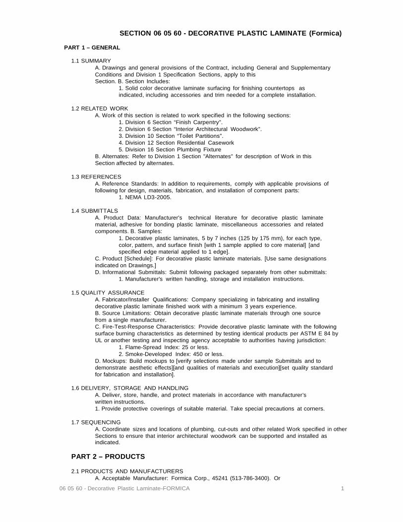
06 05 60 - Decorative Plastic Laminate-FORMICA 1
SECTION 06 05 60 - DECORATIVE PLASTIC LAMINATE (Formica)
PART 1 – GENERAL
1.1 SUMMARY A. Drawings and general provisions of the Contract, including General and Supplementary Conditions and Division 1 Specification Sections, apply to this Section. B. Section Includes:
1. Solid color decorative laminate surfacing for finishing countertops as indicated, including accessories and trim needed for a complete installation.
1.2 RELATED WORK
A. Work of this section is related to work specified in the following sections: 1. Division 6 Section “Finish Carpentry”. 2. Division 6 Section “Interior Architectural Woodwork”. 3. Division 10 Section “Toilet Partitions”. 4. Division 12 Section Residential Casework 5. Division 16 Section Plumbing Fixture
B. Alternates: Refer to Division 1 Section "Alternates" for description of Work in this Section affected by alternates.
1.3 REFERENCES
A. Reference Standards: In addition to requirements, comply with applicable provisions of following for design, materials, fabrication, and installation of component parts:
1. NEMA LD3-2005.
1.4 SUBMITTALS A. Product Data: Manufacturer's technical literature for decorative plastic laminate material, adhesive for bonding plastic laminate, miscellaneous accessories and related components. B. Samples:
1. Decorative plastic laminates, 5 by 7 inches (125 by 175 mm), for each type, color, pattern, and surface finish [with 1 sample applied to core material] [and specified edge material applied to 1 edge].
C. Product [Schedule]: For decorative plastic laminate materials. [Use same designations indicated on Drawings.] D. Informational Submittals: Submit following packaged separately from other submittals:
1. Manufacturer's written handling, storage and installation instructions.
1.5 QUALITY ASSURANCE A. Fabricator/Installer Qualifications: Company specializing in fabricating and installing decorative plastic laminate finished work with a minimum 3 years experience. B. Source Limitations: Obtain decorative plastic laminate materials through one source from a single manufacturer. C. Fire-Test-Response Characteristics: Provide decorative plastic laminate with the following surface burning characteristics as determined by testing identical products per ASTM E 84 by UL or another testing and inspecting agency acceptable to authorities having jurisdiction:
1. Flame-Spread Index: 25 or less. 2. Smoke-Developed Index: 450 or less.
D. Mockups: Build mockups to [verify selections made under sample Submittals and to demonstrate aesthetic effects][and qualities of materials and execution][set quality standard for fabrication and installation].
1.6 DELIVERY, STORAGE AND HANDLING
A. Deliver, store, handle, and protect materials in accordance with manufacturer’s written instructions. 1. Provide protective coverings of suitable material. Take special precautions at corners.
1.7 SEQUENCING
A. Coordinate sizes and locations of plumbing, cut-outs and other related Work specified in other Sections to ensure that interior architectural woodwork can be supported and installed as indicated.
PART 2 – PRODUCTS 2.1 PRODUCTS AND MANUFACTURERS
A. Acceptable Manufacturer: Formica Corp., 45241 (513-786-3400). Or

06 05 60 - Decorative Plastic Laminate-FORMICA 2
B. Substitutions allowed upon approval by Owner’s representative or Architect. 2.2 MATERIALS AND COMPONENTS
A. Decorative Plastic Laminate: Manufacturers standard and custom decorative surface papers with melamine resins, bonded under heat and pressure to kraft paper backing sheet with phenolic resins. B. Standard Decorative Laminate – General Purpose Type - Decorative Laminate:
1. Surface burning characteristics in accordance with ASTM E84. 2. Colors and Patterns: See drawings.
C. Solid Color Decorative Laminate: 1. Grade: [Grade CC, HCS] 2. Thickness: [.040 Inches (1.02 mm)]. 3. Surface burning characteristics in accordance with ASTM E84. 4. Finish:
5. Colors and Patterns: See drawings.
2.3 ACCESSORY MATERIALS A. Adhesive for Bonding Plastic Laminate: Unpigmented contact cement.
PART 3 – EXECUTION 3.1 EXAMINATION AND PREPARATION
A. Examine surfaces for conditions that would adversely affect decorative plastic laminate surfacing.
3.2 INSTALLATION
A. General: Install decorative plastic laminate in accordance with manufacturer's written installation instructions, approved Submittals and requirements of [Division 6 Section “Finish Carpentry”] [Division 6 Section “Interior Architectural Woodwork”].
1. Provide templates and rough-in measurements.
3.3 CLEANING AND PROTECTION A. Cleaning:
1. Clean decorative plastic laminate surfaces in accordance with manufacturer's instructions.
B. Protection: 1. Do not permit construction near unprotected surfaces.
END OF SECTION 06 50 60 - Decorative Plastic Laminate-FORMICA
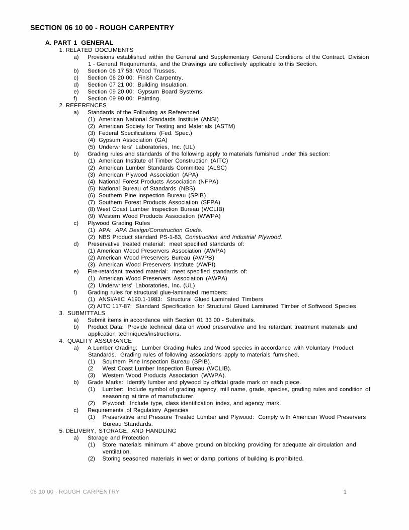
06 10 00 - ROUGH CARPENTRY 1
SECTION 06 10 00 - ROUGH CARPENTRY
A. PART 1 GENERAL 1. RELATED DOCUMENTS
a) Provisions established within the General and Supplementary General Conditions of the Contract, Division 1 - General Requirements, and the Drawings are collectively applicable to this Section.
b) Section 06 17 53: Wood Trusses. c) Section 06 20 00: Finish Carpentry. d) Section 07 21 00: Building Insulation. e) Section 09 20 00: Gypsum Board Systems. f) Section 09 90 00: Painting.
2. REFERENCES a) Standards of the Following as Referenced
(1) American National Standards Institute (ANSI) (2) American Society for Testing and Materials (ASTM) (3) Federal Specifications (Fed. Spec.) (4) Gypsum Association (GA) (5) Underwriters' Laboratories, Inc. (UL)
b) Grading rules and standards of the following apply to materials furnished under this section: (1) American Institute of Timber Construction (AITC) (2) American Lumber Standards Committee (ALSC) (3) American Plywood Association (APA) (4) National Forest Products Association (NFPA) (5) National Bureau of Standards (NBS) (6) Southern Pine Inspection Bureau (SPIB) (7) Southern Forest Products Association (SFPA) (8) West Coast Lumber Inspection Bureau (WCLIB) (9) Western Wood Products Association (WWPA)
c) Plywood Grading Rules (1) APA: APA Design/Construction Guide. (2) NBS Product standard PS-1-83, Construction and Industrial Plywood.
d) Preservative treated material: meet specified standards of: (1) American Wood Preservers Association (AWPA) (2) American Wood Preservers Bureau (AWPB) (3) American Wood Preservers Institute (AWPI)
e) Fire-retardant treated material: meet specified standards of: (1) American Wood Preservers Association (AWPA) (2) Underwriters' Laboratories, Inc. (UL)
f) Grading rules for structural glue-laminated members: (1) ANSI/AIIC A190.1-1983: Structural Glued Laminated Timbers (2) AITC 117-87: Standard Specification for Structural Glued Laminated Timber of Softwood Species
3. SUBMITTALS a) Submit items in accordance with Section 01 33 00 - Submittals. b) Product Data: Provide technical data on wood preservative and fire retardant treatment materials and
application techniques/instructions. 4. QUALITY ASSURANCE
a) A Lumber Grading: Lumber Grading Rules and Wood species in accordance with Voluntary Product Standards. Grading rules of following associations apply to materials furnished. (1) Southern Pine Inspection Bureau (SPIB). (2 West Coast Lumber Inspection Bureau (WCLIB). (3) Western Wood Products Association (WWPA).
b) Grade Marks: Identify lumber and plywood by official grade mark on each piece. (1) Lumber: Include symbol of grading agency, mill name, grade, species, grading rules and condition of
seasoning at time of manufacturer. (2) Plywood: Include type, class identification index, and agency mark.
c) Requirements of Regulatory Agencies (1) Preservative and Pressure Treated Lumber and Plywood: Comply with American Wood Preservers
Bureau Standards. 5. DELIVERY, STORAGE, AND HANDLING
a) Storage and Protection (1) Store materials minimum 4" above ground on blocking providing for adequate air circulation and
ventilation. (2) Storing seasoned materials in wet or damp portions of building is prohibited.

06 10 00 - ROUGH CARPENTRY 2
(3) Protect sheet materials from broken corners and damaged surfaces. (4) Stack framing lumber to ensure proper ventilation and drainage.
6. Preconstruction conference a) Attendees shall include:
(1) Forming subcontractor (2) Project Manager (3) Project Superintendent (4) Owner's Representateve (5) Structural Engineer (6) Architect
B. PART 2 PRODUCTS
1. MATERIALS a) General
(1) Dimensions: Indicated lumber dimensions are nominal. Actual dimensions conform to industry standards established by ALSC and the Rules Writing Agencies.
(2) Provide materials required for Work under this section suitable for intent and purpose specified. Any species meeting code requirements acceptable unless otherwise specified. Sizes indicated are nominal. Conform to NBS product standard PS-20-70 (Reaffirmed 1981), "American Softwood Lumber Standard" to actual sizes. Provide S4S lumber, surfaced four sides, unless otherwise indicated.
(3) Moisture content: 15% maximum at time of permanent closing in of building or structure, except as otherwise indicated.
b) Wood Grounds, Nailers, and Blocking (1) Provide where required for attachment of other work, including, but not limited to:
(a) Edges of siding not terminating on a structural member. (b) Handrailing attachments. (c) HVAC unit and duct terminations in walls and ceilings. (d) Base and wall cabinets. (e) Toilet accessories (especially grab bars and medicine cabinets). (f) Window covering attachments. (g) Where plates do not form a firestop at each ceiling floor level and attic. (h) On steel members for gypsum board, gypsum sheathing, and plywood attachment. (i) Attic scuttle holes.
(2) Form to shapes cut as necessary for true line and level of work to be attached. (3) Coordinate location with other work involved. (4) Attach to substrates to support applied loading. At blocking between joists and rafters, toenail each
side, each end with 2-8d nails or splice through using 2-16d nails. See structural notes. (5) Provide permanent grounds of dressed, preservative treated, key beveled lumber not less than 1/2
inch wide, and of thickness required to bring face of ground to exact thickness of finish material involved.
(6) Provide manufacturer's certificates. c) Wood Furring
(1) Install plumb and level with closure strips at edges and openings. (2) Shim with wood as required for tolerance of finished work.
d) Lumber (1) See structural notes per plans.
e) Sheet Materials (1) Plywood, thicknesses indicated:
(a) Roof decking: APA rated sheathing exterior, OSB or CDX, 19/32", or as shown on plans and approved by Owner's Representative.
(b) Combined subfloor plywood APA rated 24" O.C. OSB "T&G", 23/32" minimum, or as specified by structural engineer and approved by Owner's Representative.
(2) Gypsum sheathing board: Fire-resistant 5/8" thickness, Type X, gypsum board unless specified otherwise, and approved by Owner's Representative.
(3) Building paper: Meeting ASTM D226-87, Type I, 15 lbs per square unperforated asphalt saturated organic felt.
f) Treated Materials (1) Preservative treated materials:
(a) Lumber: Meeting AWPA C-2-80; and AWPB LP2 for above grade use: LP22 for at or below grade use.
(b) Plywood: Meeting AWPA C-9-77: and AWPB LP2 for above grade use: LP22 for at or below grade use.
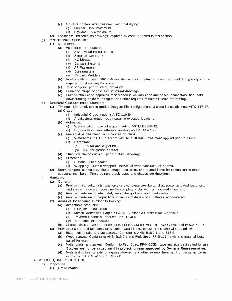
06 10 00 - ROUGH CARPENTRY 3
(c) Moisture content after treatment and final drying: (i) Lumber: 19% maximum (ii) Plywood: 15% maximum
(2) Locations: Indicated on drawings, required by code, or noted in this section. g) Miscellaneous Specialties
(1) Metal items: (a) Acceptable manufacturers:
(i) Silver Metal Products, Inc. (ii) Simpson Company (iii) KC Metals (iv) Carlson Systems (v) AF Fasteners (vi) Steelmasters (vii) Certified Welders
(b) Roof sheathing clips: 6063 T-6 extruded aluminum alloy or galvanized steel "H" type clips: size required for sheathing thickness.
(c) Joist hangers: per structural drawings. (d) Hurricane straps or ties: Per structural drawings. (e) Provide other code approved miscellaneous column caps and bases, connectors, ties, hold-
down framing anchors, hangers, and other required fabricated items for framing. h) Structural Glue-Laminated Members
(1) Timbers: Kiln dried, stress graded Douglas Fir: configurations & sizes indicated: meet AITC 117-87. (a) Grade:
(i) Industrial Grade meeting AITC 110-84. (ii) Architectural grade, rough sawn at exposed locations.
(b) Adhesive: (i) Wet condition: use adhesive meeting ASTM D2559-82. (ii) Dry condition: use adhesive meeting ASTM D3024-78.
(c) Preservative treatment: As indicated on plans: (i) Waterborne, CCA: in accord with AITC 109-84: treatment applied prior to gluing. (ii) Retention:
(a) 0.25 for above ground (b) 0.40 for ground contact
(d) Structural characteristics: per structural drawings. (e) Protection:
(i) Surface: Ends sealed. (ii) Wrapping: Bundle wrapped. Individual wrap Architectural beams.
(2) Beam hangers, connectors, plates, straps, ties, bolts, and related items for connection to other structural members: Prime painted steel: sizes and shapes per drawings.
i) Hardware (1) General
(a) Provide nails, bolts, nuts, washers, screws, expansion bolts, clips, power actuated fasteners, and similar hardware necessary for complete installation of indicated materials.
(b) Provide hardware to adequately resist design loads and meet codes. (c) Provide hardware of proper type to secure materials to substrates encountered.
(2) Adhesive for adhering subfloor to framing: (a) Acceptable products:
(i) DAP, Inc.: DAP 4000 (ii) Miracle Adhesives Corp.: SFA-66, Subfloor & Construction Adhesive (iii) Rexnord Chemical Products, Inc., PL400 (iv) Surebond, Inc.: SB400
(b) Characteristics: Meets requirements of FHA UM-60, AFG-01, IBCO-2465, and BOCA 69-26. (3) Provide anchors and fasteners for securing wood items, unless noted otherwise as follows:
(a) Bolts, nuts, studs, and lag screws: Conform to ANSI B18.2.1 and B18.5. (b) Wood screws: Conform to ANSI B18.6.1 and Fed. Spec. FF-S-111: style and material best
suited for use. (c) Nails, brads, and spikes: Conform to Fed. Spec. FF-N-105B: type and size best suited for use.
Staples are not permitted on this project, unless approved by Owner's Representative. (d) Nails and spikes for exterior exposed-to-view and other exterior framing: Hot dip galvanize in
accord with ASTM A153-82, Class D. 2. SOURCE QUALITY CONTROL
a) Inspection (1) Grade marks:

06 10 00 - ROUGH CARPENTRY 4
(a)General: Identify all lumber and plywood by official grade mark of agency approved by ALSC Board of Review.
(b)Lumber grading: (i)Grade stamp to contain symbol of grading agency, mill number or name, grade of lumber,
species or species grouping, or combination designation, rules under which graded, where applicable, and condition of seasoning at time of manufacture.
(ii)Conform to PS 20-70 (Reaffirmed 1981) with amendments, for grading of species used. Current edition of applicable association grading rules govern. All lumber 2" or less in thickness shall bear grade mark of an ALSC Board of Review approved agency.
(c)Softwood plywood: appropriate grade trademark of APA, indicate: (i)Type, grad, class, and identification index. (ii)Inspection and testing agency mark. (iii)Structural glue laminated members: Identify each member with Quality Mark indicating
compliance with ANSI/AITC A190.1-1983.
C. PART 3 EXECUTION 1. ERECTION
a) Accurately lay out Work to provide correct openings to receive other trades. (1 Lay out Work in accord with allowable tolerances indicated in Article 3.03 below. (2) Cut wood framing and carpentry Work square on bearings, closely fitted, accurately set to required
lines and levels, and rigidly secured in place. (3) Install all wood framing, necessary blocking, rough bucks, and furring, required by drawings and
necessary for proper installation of millwork and other finish carpentry. b) Temporary Supports
(1) Make wood centering or other necessary supports for openings in masonry walls accurate and strong. Properly brace and secure in position until masonry has thoroughly set.
(2) Provide blocking indicated on drawings and required. Secure blocking firmly with anchors at not more than 2'-0" off center.
2. INSTALLATION a) Stud Framing
(1) Provide single bottom plate and double top plates for partitions. (2) Provide studs in continuous lengths without splices. (3) Endnail studs to bottom plate: Endnail to lower top plate. (4) Overlap double top plate full width at corners and intersections. (5) Face nail upper top plate to lower top plate. (6) Nail bottom plate to wood construction. (7) Anchor bottom plate to concrete structure per structural drawings
(a)Coordinate location of all holdowns shown on structural drawings with concrete subcontractor prior to placement of concrete.
(8) Triple studs at corners and partition intersections, unless noted otherwise. (9) Locate extra joist where indicated on drawings. (10) Frame openings for load bearing partitions per plans: (11) Frame openings for non-load bearing partitions with single stud, single jack stud each side of opening
and headers. (12) Load bearing walls:
(a) General: Space studs per plans. (13) Non-load bearing interior partitions:
(a) General: Space studs per plans. (14) Use plywood at exterior outside corners, both corners, full height, same thickness as sheathing.
Attachment indicated in Sheet Material Installation paragraph below. b) Headers
(1) Provide continuous headers, same width as studs, depth required to span opening with required steel or plywood flitch plate per local code load requirements. Typical, unless noted otherwise
(2) Backnail headers to studs and open framing. (3) Lap headers at intersections with bearing partitions or tie with metal straps.
c) Blocking (1) Wedge, align, and anchor blocking with nails. (2) Coordinate blocking with locations of finishing materials, fixtures, specialty items, and trim.
d) Joist Framing (1) Install with crown edge up (2) Support ends of each member minimum 1 1/2" of bearing on wood or steel. Support ends of each
member in metal joist hangers, full depth of bearing at beams or headers. (3) Lap members framing from opposite sides of beams, girders, or partitions minimum 3 1/2" or tie

06 10 00 - ROUGH CARPENTRY 5
opposing members by toenailing or metal connectors. (4) Notches in joists: Prohibited unless approved by Engineer in writing. (5) Bored holes: See details on plans. Verify acceptability of size and location of any hole not detailed,
prior to boring. e) Rafter Framing
(1) Cut rafters to set on exterior wall plates. Shim and toenail to plate. (2) Place rafters directly opposite each other at ridge, and nail to ridge member. Provide bridging where
indicated. f) Straps or ties
(1) Straps or ties shall not be nailed off until building is fully loaded. g) Structural Glue-Laminated Members
(1) Metal connectors: Install at locations and configurations indicated in accord with reviewed shop drawings.
(2) Timbers: Set in designated locations in accord with reviewed shop drawings and AITC recommendations.
h) Sheet Material Installation (1) Plywood roof deck:
(a) Provide with face grain perpendicular to supports; terminate panels over supports; stagger end joints of adjacent panels.
(b) Allow 1/8" between end joints and 1/8" between edge joints for expansion and contraction. (c) Attach plywood per structural plans. (d) Install roof sheathing clips at roof sheathing midspan. (e) Note: Use of staples is prohibited, without written permission from Owner's
Representative. (2) Subfloor plywood:
(a) Lay with face grain perpendicular to supports: terminate panels over supports: stagger end joints in adjacent panels
(b) Allow 1/16" space between all edges. (c) Lay glue bead on each joist for glue and nail construction. Install in accord with manufacturer's
product data. (d) Attach plywood per structural plans.
(3) Sheathing (a) Per structural drawings.
3. APPLICATION a) Tolerances, unless indicated otherwise:
(1) Variation from plumb: 1/4" in 10'-0" height, cumulative. (2) Variation in horizontal squaring diagonals: 1/2" (3) Variation in room horizontal squaring diagonals: 1/4" (4) Variation in walls from tangent line (straightness): 1/4" in 10'-0" non-cumulative (5) Variation in location of walls from dimension: 1/4" (6) Location of dimensioned openings: +3/8" (7) Variation in rough opening size + 1/8"
END OF SECTION 06 10 00 - ROUGH CARPENTRY

SECTION 06 16 00 - SHEATHING 1
SECTION 06 16 00 – SHEATHING
PART 1- GENERAL 1.01 SECTION REQUIREMENTS
A. Submittals: Model code evaluation reports for foam-plastic sheathing and building wrap.
B. Product Data: For each type of process and factory-fabricated product. Indicate component materials and dimensions and include construction and application details.
1. Include data for wood-preservative treatment from chemical treatment manufacturer and certification by treating plant that treated materials comply with requirements. Indicate type of preservative used, net amount of preservative retained, and chemical treatment manufacturer's written instructions for handling, storing, installing, and finishing treated material.
2. For products receiving a waterborne treatment, include statement that moisture content of treated materials was reduced to levels specified before shipment to Project site.
3. Include copies of warranties from chemical treatment manufacturers for each type of treatment. C. Material Certificates: For building sheathing specified to comply with minimum allowable unit stresses. Indicate species and grade selected for each use and design values approved by the American Lumber Standards Committee Board of Review. D. Research/Evaluation Reports: For the following, showing compliance with building code in effect for Project:
1. Preservative-treated wood.
2. Engineered wood products.
PART 2 - PRODUCTS
2.01 WOOD PANEL PRODUCTS, GENERAL
A. Plywood: DOC PS 1. B. Oriented Strand Board: DOC PS 2.
2.02 TREATED PLYWOOD
A. Preservative-Treated Plywood: AWPA C9.
1. Use treatment containing no arsenic or chromium. 2. Kiln-dry plywood after treatment to a maximum moisture content of 15 percent.
B. Provide preservative treated plywood for plywood in contact with masonry or concrete, vapor barriers, and waterproofing.
2.03 EXTERIOR WALL SHEATHING
A. Plywood Wall Sheathing: Exposure 1, Structural I sheathing. B. Oriented-Strand-Board Wall Sheathing: Exposure 1, Structural I sheathing.
C. Gypsum Wall Sheathing: Cannot be used for structural sheathing, see above. Any of the following:
1. Paper-Surfaced Gypsum Wall Sheathing: ASTM C 79/C 79M or ASTM C 1396/C 1396M, gypsum sheathing; with water-resistant-treated core. 2. Glass-Mat Gypsum Wall Sheathing: ASTM C 1177/1177M.
3. Cellulose Fiber-Reinforced Gypsum Sheathing: ASTM C 1278/C 1278M, gypsum sheathing.
D. Fiberboard Wall Sheathing: Cannot be used for structural sheathing. AHA A194.1, Type IV, Grade 1 (Regular), 1/2 inch thick. E. Insulating Foam Wall Sheathing: any of the following that conforms with the local Building Codes:
1. Extruded-Polystyrene-Foam Wall Sheathing: ASTM C 578, Type IV. 2. Foil-Faced, Polyisocyanurate-Foam Wall Sheathing: ASTM C 1289, Type I, Class 2. Foam-plastic core and facings shall have flame spread of 25 or less, when tested individually.
2.04 MISCELLANEOUS PRODUCTS
A. Fasteners: Size and type indicated.
1. For roof and wall sheathing, provide fasteners with hot-dip zinc coating complying with ASTM A 153/A 153M.

SECTION 06 16 00 - SHEATHING 2
2. Power-Driven Fasteners: CABO NER-272. B. Sheathing Joint-and-Penetration Treatment Materials:
1. Sealant for Gypsum Sheathing Board: Joint sealant recommended by sheathing manufacturer for application indicated. 2. Sheathing Tape for Gypsum Sheathing Board: Self-adhering glass-fiber tape recommended by sheathing and tape manufacturers for application indicated. 3. Sheathing T ape for Foam-Plastic Sheathing: Pressure-sensitive plastic tape recommended by sheathing manufacturer for sealing joints and penetrations in sheathing.
C. Adhesives for Field Gluing Panels to Framing: APA AFG-01. D. Flexible Flashing: Adhesive rubberized-asphalt compound, bonded to polyethylene film, with an overall
thickness of 0.030 inch. PART 3 EXECUTION 3.01 INSTALLATION A. Securely attach to substrates, complying with the following:
1. CABO NER-272 for power-driven fasteners. 2. Table R602.3(1), "Fastener Schedule for Structural Members," and Table R602.3(2).
B. Sheathing Joint-And-Penetration Treatment: Seal sheathing joints according to sheathing manufacturer's
written instructions. END OF SECTION 06 16 00
SECTION 06 19 20 - WOOD TRUSSES 1
SECTION 06 19 20 - WOOD TRUSSES
PART 1 GENERAL
1.01 RELATED DOCUMENTS A. Drawings and general provisions of the Contract, including General and Supplementary Conditions and
Division 1 Specification Sections, apply to this Section.
1.02 SUMMARY A. This Section includes the following:
1. Roof trusses. 2. Truss accessories.
1.03 DEFINITIONS
A. Metal-plate-connected wood trusses include planar structural units consisting of metal-plate-connected members fabricated from dimension lumber and cut and assembled before delivery to Project site.
1.04 PERFORMANCE REQUIREMENTS
A. Structural Performance: Engineer, fabricate, and erect metal-plate-connected wood trusses to withstand design loads within limits and under conditions required. 1. Design Loads: As indicated. 2. Design trusses to withstand design loads without deflections greater than the following:
a. Roof Trusses: Vertical deflection of 1/240 of span due to total load. B. Engineering Responsibility: Engage a fabricator who uses a qualified professional engineer to prepare
calculations, Shop Drawings, and other structural data for metal-plate-connected wood trusses.
1.05 SUBMITTALS A. General: Submit each item in this Article according to the Conditions of the Contract and Division 1
Specification Sections. B. Product Data for lumber, metal-plate connectors, metal framing connectors, bolts, and fasteners. C. Shop Drawings detailing location, pitch, span, camber, configuration, and spacing for each type of truss
required; species, sizes, and stress grades of lumber to be used; splice details; type, size, material, finish, design values, and orientation and location of metal connector plates; and bearing details. 1. To the extent truss design considerations are indicated as fabricator's responsibility, include
structural analysis data signed and sealed by the qualified professional engineer responsible for their preparation.
2. Include truss Shop Drawings signed and sealed by the qualified professional engineer responsible for their preparation, registered in the State of New Mexico.
D. Product certificates signed by officer of truss fabricating firm certifying that metal-plate-connected wood trusses supplied for Project comply with specified requirements and Shop Drawings.
E. Qualification data for firms and persons specified in "Quality Assurance" Article to demonstrate their capabilities and experience. Include lists of completed projects with project names and addresses, names and addresses of architects and owners, and other information specified.
F. Material test reports from a qualified independent testing agency indicating and interpreting test results relative to compliance of fire-retardant-treated wood products with requirements indicated.
G. Warranty of chemical treatment manufacturer for each type of treatment. H. Material certificates for dimension lumber specified to comply with minimum allowable unit stresses.
Indicate species and grade selected for each use and design values approved by the American Lumber Standards Committee (ALSC) Board of Review.
I. Wood treatment data as follows, including chemical treatment manufacturer's instructions for handling, storing, installing, and finishing treated materials: 1. For each type of preservative-treated wood product, include certification by treating plant stating
type of preservative solution and pressure process used, net amount of preservative retained, and compliance with applicable standards.
2. For waterborne-treated products, include statement that moisture content of treated materials was reduced to levels indicated before shipment to truss fabricator.
3. For fire-retardant-treated wood products, include certification by treating plant that treated materials comply with specified standard and other requirements as well as data relative to bending strength, stiffness, and fastener-holding capacities of treated materials.
J. Research or evaluation reports of the model code organization acceptable to authorities having jurisdiction that evidence the following products' compliance with building code in effect for Project. 1. Fire-retardant-treated wood. 2. Metal-plate connectors. 3. Metal framing connectors.
SECTION 06 19 20 - WOOD TRUSSES 2
1.06 QUALITY ASSURANCE
A. Installer Qualifications: Engage an experienced Installer who has completed wood truss installation similar in material, design, and extent to that indicated for this Project and with a record of successful in- service performance.
B. Fabricator's Qualifications: Engage a firm that complies with the following requirements for quality control and is experienced in fabricating metal-plate-connected wood trusses similar to those indicated for this Project and with a record of successful in-service performance: 1. Fabricator participates in a recognized quality-assurance program that involves inspection by
SPIB; Timber Products Inspection, Inc.; Truss Plate Institute (TPI); or other independent inspecting and testing agency acceptable to Architect and authorities having jurisdiction.
C. Comply with applicable requirements and recommendations of the following publications: 1. ANSI/TP1 1, "National Design Standard for Metal-Plate-Connected Wood Truss Construction." 2. TPI HIB "Commentary and Recommendations for Handling Installing & Bracing Metal Plate
Connected Wood Trusses." 3. TPI DSB "Recommended Design Specification for Temporary Bracing of Metal Plate Connected
Wood Trusses." D. Metal-Plate Connector Manufacturer's Qualifications: A manufacturer that is a member of TPI and that
complies with TPI quality-control procedures for manufacture of connector plates published in ANSI/TPI 1.
E. Single-Source Responsibility for Connector Plates: Provide metal connector plates from one source and by a single manufacturer.
F. Wood Structural Design Standard: Comply with applicable requirements of AFPA's "National Design Specification for Wood Construction" and its "Supplement."
G. Single-Source Engineering Responsibility: Provide trusses engineered by metal-plate connector manufacturer to support superimposed dead and live loads indicated, with design approved and certified by a qualified professional engineer.
H. Professional Engineer Qualifications: A professional engineer who is legally authorized to practice in the jurisdiction where Project is located and who is experienced in providing engineering services of the kind indicated that have resulted in installing metal-plate-connected wood trusses similar to those indicated for this Project and with a record of successful in-service performance.
1.07 DELIVERY, STORAGE, AND HANDLING
A. Handle and store trusses with care and comply with manufacturer's written instructions and TPI recommendations to avoid damage and lateral bending.
B. Inspect trusses showing discoloration, corrosion, or other evidence of deterioration. Discard and replace trusses that are damaged or defective.
1.08 SEQUENCING AND SCHEDULING
A. Time delivery and erection of trusses to avoid extended on-site storage and to avoid delaying progress of other trades whose work must follow erection of trusses.
PART 2 PRODUCTS
2.01 MANUFACTURERS
A. Available Manufacturers: Subject to compliance with requirements, manufacturers offering products that may be incorporated into the Work include, but are not limited to, the following:
B. Manufacturers: Subject to compliance with requirements, provide products by one of the following: 1. Fire-Retardant-Treated Materials, Interior Type A:
a. Baxter: J. H. Baxter Co. b. Chemical Specialties, Inc. c. Continental Wood Preservers, Inc. d. Hickson Corporation. e. Hoover Treated Wood Products, Inc.
2. Fire-Retardant-Treated Materials, Exterior Type: a. American Wood Treaters, Inc. b. Hoover Treated Wood Products, Inc.
3. Metal Connector Plates: a. Alpine Engineered Products, Inc. b. Computrus, Inc. c. Mitek Industries, Inc. d. Robbins Manufacturing Company. e. Tee-Lok Corporation. f. Truswal Systems Corporation.

SECTION 06 19 20 - WOOD TRUSSES 3
4. Metal Framing Anchors:
a. Cleveland Steel Specialty Co. b. Harlen Metal Products, Inc. c. Silver Metal Products, Inc. d. Simpson Strong-Tie Company, Inc. e. Southeastern Metals Manufacturing Co., Inc. f. United Steel Products Co.
2.02 DIMENSION LUMBER
A. Lumber Standards: Comply with DOC PS 20, "American Softwood Lumber Standard," and with applicable grading rules of inspection agencies certified by ALSC's Board of Review.
B. Inspection Agencies: Inspection agencies, and the abbreviations used to reference them, include the following: 1. NELMA - Northeastern Lumber Manufacturers Association. 2. NLGA - National Lumber Grades Authority (Canadian). 3. SPIB - Southern Pine Inspection Bureau. 4. WCLIB - West Coast Lumber Inspection Bureau. 5. WWPA - Western Wood Products Association.
C. Grade Stamps: Provide lumber with each piece factory marked with grade stamp of inspection agency evidencing compliance with grading rule requirements and identifying grading agency, grade, species, moisture content at time of surfacing, and mill.
D. Provide dressed lumber, S4S, manufactured to actual sizes required by DOC PS 20 for moisture content specified, to comply with requirements indicated below: 1. Provide dry lumber with 19 percent maximum moisture content at time of dressing. 2. Provide lumber with 15 percent maximum moisture content at time of dressing.
E. Grade and Species: Provide dimension lumber of any species for truss chord and web members, graded visually or mechanically, and capable of supporting required loads without exceeding allowable design values according to AFPA's "National Design Specification for Wood Construction" and its "Supplement."
F. Grade and Species: Provide visually graded dimension lumber for truss chord and web members, of the following grade and species: 1. Grade for Chord Members: No. 2. 2. Grade for Web Members: No. 2. 8. Species: Any species graded per WWPA rules.
2.03 WOOD-PRESERVATIVE-TREATED MATERIALS
A. General: Where lumber is indicated as preservative treated or is specified to be treated, comply with applicable requirements of AWPA C2 (lumber). Mark each treated item with the Quality Mark Requirements of an inspection agency approved by ALSC's Board of Review.
B. Pressure treat aboveground items with waterborne preservatives to a minimum retention of 0.25 lb/cu. ft. After treatment, kiln-dry lumber to a maximum moisture content of 19 percent.
C. Complete fabrication of treated items before treatment, where possible. If cut after treatment, apply field treatment complying with AWPA M4 to cut surfaces. Inspect each piece of lumber after drying and discard damaged or defective pieces.
2.04 FIRE-RETARDANT-TREATED MATERIALS
A. General: Where fire-retardant-treated wood is indicated, comply with applicable requirements of AWPA C20 (lumber). Identify fire-retardant-treated wood with appropriate classification marking of UL, U.S. Testing, Timber Products Inspection, or another testing and inspecting agency acceptable to authorities having jurisdiction. 1. Research or Evaluation Reports: Provide fire-retardant-treated wood acceptable to authorities
having jurisdiction and for which a current model code research or evaluation report exists that evidences compliance of fire-retardant-treated wood for application indicated.
B. Interior Type A: For interior locations, use chemical formulation that produces treated lumber with the following properties under conditions present after installation: 1. Bending strength, stiffness, and fastener-holding capacities are not reduced below values
published by manufacturer of chemical formulation under elevated temperature and humidity conditions simulating installed conditions when tested by a qualified independent testing agency.
2. No form of degradation occurs due to acid hydrolysis or other causes related to treatment. 3. Contact with treated wood does not promote corrosion of metal fasteners.
C. Exterior Type: Use for exterior locations and where indicated. D. Inspect each piece of treated lumber after drying and discard damaged or defective pieces.

SECTION 06 19 20 - WOOD TRUSSES 4
2.05 METAL CONNECTOR PLATES
A. General: Fabricate connector plates from metal complying with requirements indicated below.
B. Hot-Dip Galvanized Steel Sheet: Structural-quality steel sheet, zinc coated by hot-dip process complying with ASTM A 653, G60 coating designation; Grade 33 and not less than 0.0359 inch thick.
C. Electrolytic Zinc-Coated Steel Sheet: ASTM A 591, structural-(physical) quality steel sheet, zinc coated
by electrodeposition; 33,000-psi minimum yield strength, coating class C, and not less than 0.0474 inch thick.
D. Aluminum-Zinc Alloy-Coated Steel Sheet: Structural-(physical) quality steel sheet, aluminum-zinc alloy- coated by hot-dip process complying with ASTM A 792, AZ50 coating designation; Grade 33 and not less than 0.0359 inch thick.
E. Stainless-Steel Sheet: ASTM A 666, Type 304 or 316, chromium nickel steel sheet; 33,000-psi minimum yield strength and not less than 0.035 inch thick.
2.06 FASTENERS
A. General: Provide fasteners of size and type indicated that comply with requirements specified below for material and manufacture. 1. Where truss members are exposed to weather or to high relative humidities, provide fasteners
with a hot-dip zinc coating per ASTM A 153 or of stainless steel, Type 304 or 316. B. Nails, Wire, Brads, and Staples: FS FF-N-105.
C. Power-Driven Fasteners: CABO NER-272. D. Wood Screws: ASME B18.6.1. E. Lag Bolts and Screws: ASME B18.2.1. F. Bolts: Steel bolts complying with ASTM A 307, Grade A; with ASTM A 563 hex nuts and, where
indicated, flat washers.
2.07 METAL FRAMING ANCHORS A. General: Provide metal framing anchors of structural capacity, type, size, metal, and finish indicated
that comply with requirements specified, including the following: 1. Research or Evaluation Reports: Provide products for which model code research or evaluation
reports exist that are acceptable to authorities having jurisdiction and that evidence compliance of metal framing anchors for application indicated with building code in effect for this Project.
2. Allowable Design Loads: Provide products with allowable design loads, as published by manufacturer, that meet or exceed those indicated. Manufacturer's published values shall be determined from empirical data or by rational engineering analysis, and demonstrated by comprehensive testing performed by a qualified independent testing agency.
B. Galvanized Steel Sheet: Hot-dip, zinc-coated steel sheet complying with ASTM A 653, G60 coating designation; structural, commercial, or lock-forming quality, as standard with manufacturer for type of anchor indicated.
C. Stainless-Steel Sheet: ASTM A 666, Type 304 or 316, chromium nickel steel sheet; 33,000-psi minimum yield strength.
2.08 MISCELLANEOUS MATERIALS
A. Galvanizing Repair Paint: SSPC-Paint 20 or DOD-P-21035, with dry film containing a minimum of 94 percent zinc dust by weight.
B. Protective Coatings: Provide one of the following coating systems: 1. SSPC-Paint 22, epoxy-polyamide primer. 2. SSPC-Paint 16, coal-tar epoxy-polyamide black or dark red paint. 3. SSPC-Paint 27 and SSPC-Paint 12, basic zinc chromate-vinyl butyral wash primer and cold-
applied asphalt mastic.
2.09 FABRICATION A. Cut truss members to accurate lengths, angles, and sizes to produce close-fitting joints. B. Fabricate metal connector plates to size, configuration, thickness, and anchorage details required to
withstand design loadings for types of joint designs indicated. C. Assemble truss members in design configuration indicated using jigs or other means to ensure
uniformity and accuracy of assembly with joints closely fitted to comply with tolerances of ANSI/TPI 1. Position members to produce design camber indicated. 1. Fabricate wood trusses within manufacturing tolerances of ANSI/TPI 1.
D. Connect truss members by metal connector plates located and securely embedded simultaneously into both sides of wood members by air or hydraulic press.

SECTION 06 19 20 - WOOD TRUSSES 5
PART 3 EXECUTION
3.01 INSTALLATION A. Do not install wood trusses until supporting construction is in place and is braced and secured. B. Before installing, splice trusses delivered to Project site in more than one piece.
C. Hoist trusses in place by lifting equipment suited to sizes and types of trusses required, exercising care
not to damage truss members or joints by out-of-plane bending or other causes. D. Install and brace trusses according to recommendations of TPI and as indicated. E. Install trusses plumb, square, and true to line and securely fasten to supporting construction. F. Space, adjust, and align trusses in location before permanently fastening and as follows:
1. Truss Spacing: As indicated on drawings. G. Anchor trusses securely at all bearing points using metal framing anchors. Install fasteners through
each fastener hole in metal framing anchor according to manufacturer's fastening schedules and written instructions.
H. Securely connect each truss ply required for forming built-up girder trusses. 1. Anchor trusses to girder trusses as indicated.
I. Install and fasten permanent bracing during truss erection and before construction loads are applied. Anchor ends of permanent bracing where terminating at walls or beams.
J. Install wood trusses within installation tolerances of ANSI/TPI 1. K. Do not cut or remove truss members. L. Return wood trusses that are damaged or do not meet requirements to fabricator and replace with
trusses that do meet requirements. 1. Do not alter trusses in the field.
3.02 REPAIRS AND PROTECTION
A. Repair damaged galvanized coatings on exposed surfaces with galvanized repair paint according to ASTM A 780 and manufacturer's written instructions.
B. Protective Coating: Clean and prepare exposed surfaces of embedded-metal connector plates. Brush apply primer, when part of coating system, and one coat of protective coating. 1. Apply materials to provide minimum dry film thickness recommended by manufacturer of coating
system. END OF SECTION 06 19 20

06 20 00 - FINISH CARPENTRY 1
SECTION 06 20 00 - FINISH CARPENTRY
A. PART 1 GENERAL 1. RELATED DOCUMENTS
a) Provisions established within the General and Supplementary General Conditions of the Contract, Division 1 - General Requirements , and the Drawings are collectively applicable to this Section.
b) Section 06 10 00: Rough Carpentry c) Section 06 17 53: Wood Trusses d) Section 06 41 00: Cabinet Work e) Section 07 62 00: Sheet Metal Flashing and Trim f) Section 07 92 00: Sealants and Caulking g) Section 08 10 00: Packaged Doors and Frames h) Section 09 20 00: Gypsum Board Systems i) Section 09 90 00: Painting
2. REFERENCES a) Standards of the Following as Referenced
(1) Architectural Woodwork Institute (AWI) (2) American National Standards Institute (ANSI) (3) National Electrical Manufacturer's Association (NEMA)
b) Industry Standards (1) AWI: Quality Standards, Guide Specifications, and Quality Certification Program, 1985
edition. c) Grading rules and standards of the following apply to materials furnished under this section:
(1) American Lumber Standards Committee (ALSC) (2) American Plywood Association (APA) (3) National Hardware Lumber Association (NHLA) (4) National Bureau of Standards (NBS) Voluntary Product Standards (PS) (5 )West Coast Lumber Inspection Bureau (WCLIB) (6) Western Wood Products Association (WWPA)
d) Preservative treated material: meet specified standards of: (1) American Wood Preservers Association (AWPA) (2) American Wood Preservers Bureau (AWPB) (3) American Wood Preservers Institute (AWPI)
e) Plywood Grading Rules (1) Softwood plywood: NBS PS-1-83 (2) Hardwood plywood: NBS PS-51-71
3. SUBMITTALS a) Samples, submit as follows:
(1) Finish samples: Indicate selected finishes on samples of species and grade material specified.
(2) Hardware items: Submit, if requested by Owner's Representative, samples will be returned to supplier.
4. DELIVERY, STORAGE, AND HANDLING a) Schedule delivery of finish carpentry Work to Project site to coincide with installation but not to
cause delay in Work. b) Immediately upon delivery to Project site, place materials indoors, under cover, protected from
weather. c) Store materials minimum 6" above ground on framework or blocking; cover with protective
waterproof covering providing for adequate air circulation and ventilation. Store in dry space. 5. PROJECT CONDITIONS
a) Field measurements: Take field measurements to determine exact millwork sizes. Indicate exact dimensions on shop drawings.
b) Installation of interior finish carpentry or millwork until spaces are enclosed, and dry is prohibited.
B. PART 2 PRODUCTS
1. MATERIALS a) General
(1) Dimensions: Indicated lumber dimensions are nominal. Actual dimensions conform to industry standards established by ALSC and the Rules Writing Agencies.
(2) Moisture content: 12% maximum. (3) Surfacing: Surface four sides, S4S, unless otherwise indicated. (4) Grades for exposed and semi-exposed finish carpentry and millwork and plywood are
06 20 00 - FINISH CARPENTRY 2
based on AWI Quality Standards. Grades for unexposed Work are based on Rules Writing Agencies grading rules.
b) Lumber (1) Species and grades
(a) Unexposed millwork framing and blocking: (i) 1" by 4": Standard Grade West Coast Lumber (ii) Members larger than 2" by 4": #2 grade
(b) Door frames: Prehung: Custom Grade White Pine, kiln dried (KD) c) Sheet Material
(1) Plywood: Thicknesses indicated (a) Plywood soffits: APA 303, 6-W rough sawn fir. (b) Unexposed and semi-exposed millwork and general carpentry: APA A-C G-1,
Exterior. e) Interior
(1) Floor base (2) Window and door trim
a) Shop Finishing (1) Finish millwork items in accord with finishing requirements of Painting section. (2) Provide finish Work smooth, free from abrasion, tool marks, raised grain, and other Grade
prohibited defects on exposed surfaces. b) Tolerances: Fabricate millwork items to AWI Custom Grade unless otherwise indicated.
3. SOURCE QUALITY CONTROL a) Inspection
(1) Grade marks: (a) Identify lumber and plywood by official grade mark. (b) Lumber grade stamp to contain symbol of grading agency, mill number or name,
grade of lumber, species or species grouping, or combination designation, rules under which graded, where applicable, and condition of seasoning at time of manufacture.
(c) Plywood: Appropriate grade trademark of APA. Indicate type, grade, class and identification index, and inspection and testing agency mark.
(d) Conceal grade marks on components to be exposed to view in finished Work.
C. PART 3 EXECUTION 1. PREPARATION
a) General (1) Install Work plumb, level, true, and straight without distortions: conceal shims. (2) Provide finish Work smooth, free from abrasion, tool marks, raised grain markings, or
similar defects on exposed surfaces. (3) Cut Work to fit unless specified to be shop fabricated or shop cut to exact size. Where
carpentry and millwork abuts other finished Work, scribe and cut for accurate fit. Drill pilot holes at corners before making cut-outs.
(4) Distribute defects allowed in quality grade specified to best overall advantage when installing job assembled Work.
2. INSTALLATION. a) Hardware: Install where indicated in accord with particular hardware specialty manufacturer's
installation instructions. 3. CLEANING
a) Clean wood, metal, and accessory items using neutral cleaner. Check and correct operating mechanisms for proper operation. Adjust and lubricate hinges, catches, and other operating hardware.
4. PROTECTION a) Protect finished and prefinished surfaces from Work of other trades. b) Prior to Date of Completion, examine Work for damage. Repair or replace damaged areas to
original condition. END OF SECTION 06 20 00 - FINISH CARPENTRY

06 41 00 Architectural Wood Casework 1
SECTION 06 41 00 – ARCHITECTURAL WOOD CASEWORK
A. PART 1 GENERAL 1. RELATED DOCUMENTS
a) Provisions established within the General and Supplementary General Conditions of the Contract, Division 1 - General Requirements, and the Drawings are collectively applicable to this Section.
b) Section 06 10 00 - Rough Carpentry. c) Section 06 20 00 - Finish Carpentry. d) Section 07 92 13 - Sealants and Caulking. e) Section 09 20 00 - Gypsum Board Systems.
2. REFERENCES a) Standards of the following as referenced:
(1) American National Standards Institute (ANSI). (2) American Woodworking Institute (AWI). (3) National Bureau of Standards (NBS) Product Standard (PS). (4) National Electrical Manufacturer's Association (NEMA). (5) National Kitchen Cabinet Association (NKCA).
b) Industry Standards: (1) AWI: Quality Standards, Guide Specifications, and Quality Certification Program, 1985 Edition. (2) NBS: PS-51: Hardwood and Decorative Plywood. (3) NKCA / ANSI: A161.1-1985: Recommended Performance and Construction Standards for
Kitchen and Vanity Cabinets. 3. SUBMITTALS
a) Mock-up: Submit one (1) full-size, 18-inch wide base cabinet illustrating construction and material proposed for the project, including countertop with backsplash, end splash, and finished end.
b) Shop Drawings: (1) Indicate elevations, section, and layouts of individual items. Show all dimensions. (2) Take field dimensions at each unit where critical prior to fabrication of Work for cabinets. (3) Take field dimensions for countertops at each individual unit; verify for proper length and fit. (4) Indicate all materials and methods of construction.
c) Product Data: Include cabinet manufacturer's material list and construction specification, including hardware and finishes.
d) Color samples: Submit granite countertop for color selections by Owner's Representative. 4. DELIVERY, STORAGE AND HANDLING
a) Deliver cabinet work to project site in manufacturer's protective packaging and only after building is enclosed, finished, and ready for cabinet installation. Storage of cabinet Work at project site is prohibited.
b) Store equipment in packaging to prevent soiling or physical damage. c) Handle items to prevent racking or warping of cabinets, and damage to finished surfaces and
operating mechanisms. Repair or replace damaged Work. 5. PROJECT CONDITIONS
a) Protection: Protect prefinished surfaces from damage or staining. Provide protective covering for equipment following installation until Date of Completion.
6. WARRANTY a) Furnish manufacturer's standard cabinet warranty as part of Project Closeout Documents.
B. PART 2 PRODUCTS
1. MANUFACTURERS a) Product Spec:
(1) Manufacturer: Lanz or other manufacturer producing equal quality products. (2) Door Type: Flat panel. (3) Frame: : ¾ “ solid hardwood – glued and screw doweled. (4) Finish: Thermafoil TBD. (5) Hinges: Concealed, 110 degree 6-way adjustable. (6) Drawer guides: Side mounted, 75# capacity with mechanism that prevents easy pull-out. (7) Shelves: Adjustable on upper and lower cabinets. (8) Interior: Maple print or white melamine interior. (9) Finished Ends: Thermafoil. (10) Shelf supports: metal pins drilled in.
b) Substitutions: Under provisions of Section 01 25 00 - Product Options and substitutions. 2. CUSTOM MANUFACTURED UNITS
a) Provide shop drawings and details for Owner's Representative's approval.

06 41 00 – ARCHITECTURAL WOOD CASEWORK 2
3. FABRICATION a) Shop Assembly:
(1) General Construction: Provide cabinets fabricated with all wooded jointed and glued construction.
(2) Fabricate items of woodwork in mill as far as practical. Where countertops cannot be furnished in single length, join using "Tite-Joint" fasteners.
(3) Provide joints at logical break points for items which cannot be manufactured in one piece; note joints on shop drawings.
(4) Scribe, miter and accurately join work. b) Shop Finishing:
(1) Provide finish work smooth, free from abrasion, tool marks, raised grain, and other grade prohibited defects on exposed surfaces.
C. PART 3 EXECUTION
1. EXAMINATION a) Inspect each unit before installation of work for suitable substrate and square and plumb walls under
this Section. Notify Contractor, in writing, of unsatisfactory conditions. Proceeding with installation of work under this Section indicates acceptance of substrate.
2. INSTALLATION a) Cabinets
(1 )Install cabinets plumb, level and true to line; secure to floor and wall surfaces in accordance with reviewed shop drawings. Scribe work to adjacent surfaces.
(2) Coordinate work with installation of work of other trades required to be built into cabinets. b) Countertops:
(1) Install countertops plumb, level and true to line; secure to cabinets and wall surfaces in accordance with reviewed shop drawings. Scribe work to adjacent surfaces.
(2) Coordinate work with installation of work of other trades required to be built into cabinets. 3) Shop Fabrication
(i) Where countertops cannot be furnished in single length, join using industry standard materials. Granite at joined materials to match as closely as possible.
(4) Provide joints at logical break points for items which cannot be manufactured in one piece: note joints on shop drawings.
(5) Scribe, miter, and accurately join Work. b) Shop Finishing
(1) Finish millwork items in accord with finishing requirements of Painting section. (2) Provide finish Work smooth, free from abrasion, tool marks, raised grain, and other Grade
prohibited defects on exposed surfaces. c) Tolerances: Fabricate millwork items to AWI Custom Grade unless otherwise indicated.
3. PROTECTION a) Protect finished surfaces from damaged or staining resulting from subsequent work. Repair or replace
damaged cabinetwork, including warped or loose members. END OF 06 41 00 – ARCHITECTURAL WOOD CASEWORK
SECTION 06 41 93 –CASEWORK HARDWARE
A. PART 1 GENERAL 1. RELATED DOCUMENTS
a) Provisions established within the General and Supplementary General Conditions of the Contract, Division 1 - General Requirements, and the Drawings are collectively applicable to this Section.
b) Section 06 10 00 - Rough Carpentry. c) Section 06 20 00 - Finish Carpentry. d) Section 09 20 00 - Gypsum Board Systems.
2. REFERENCES a) Standards of the following as referenced:
(1) American National Standards Institute (ANSI). (2) American Woodworking Institute (AWI). (3) National Bureau of Standards (NBS) Product Standard (PS). (4) National Electrical Manufacturer's Association (NEMA). (5) National Kitchen Cabinet Association (NKCA).
b) Industry Standards: (1) AWI: Quality Standards, Guide Specifications, and Quality Certification Program, 1985 Edition. (2) NBS: PS-51: Hardwood and Decorative Plywood. (3) NKCA / ANSI: A161.1-1985: Recommended Performance and Construction Standards for
Kitchen and Vanity Cabinets. 3. SUBMITTALS
a) Mock-up: Submit one (1) full-size piece of hardware installed on cabinet (see cabinet submittal) to Architect or Owner’s Representative.
4. DELIVERY, STORAGE AND HANDLING a) Deliver to project site in manufacturer's protective packaging and only after building is enclosed,
finished, and ready for installation. b) Store equipment in packaging to prevent soiling or physical damage. c) Handle items to prevent damage to finished surfaces.
5. PROJECT CONDITIONS a) Protection: Protect finished surfaces from damage or staining. Provide protective covering for
equipment following installation until Date of Completion. 6. WARRANTY
a) Furnish manufacturer's standard warranty as part of Project Closeout Documents.
B. PART 2 PRODUCTS 1. MANUFACTURERS
a) Product Spec: (1) Manufacturer: SUGATSUNE or other manufacturer producing equal quality products.
a)SN-50/S (1 31/31” long x 5/8” High x 1 ½” Deep, cabinet 2 hole door pull. Hole spacing 1 3/16”, stainless steel.)
b) Substitutions: Under provisions of Section 01 25 00 - Product Options and substitutions.
C. PART 3 EXECUTION 1. EXAMINATION
a) Inspect each unit before. Notify Contractor, in writing, of unsatisfactory conditions. Proceeding with installation of work under this Section indicates acceptance of materials.
2. INSTALLATION a) Door Hardware
Make sure level and true. 3. PROTECTION
a) Protect finished surfaces from damaged or staining resulting from subsequent work. Repair or replace damaged work.
END OF 06 41 93 – CASEWORK HARDWARE
06 41 17 Casework Hardware 1

07 13 53 - ELASTOMERIC SHEET MEMBRANE WATERPROOFING
SECTION 07 13 53 - ELASTOMERIC SHEET MEMBRANE WATERPROOFING A. PART 1: GENERAL
1. RELATED DOCUMENTS a) Provisions established within the General and Supplementary General Conditions of the Contract,
Division 1 - General Requirements, and the Drawings are collectively applicable to this Section. 2. SECTION INCLUDES
a) Sheet membrane waterproofing over wood decking at deck floors. b) Primer, Mastic, and Accessories.
3. SUBMITTALS a) General: Submit following items under provisions of Section 01 33 00 - Submittals. b) Product Data: Submit manufacturer's technical literature for each product. c) Shop Drawings: Submit details indicating special joint or termination conditions and special conditions of
interface with other materials. d) Manufacturer's Instruction: Submit manufacturer's printed installation instructions for each product;
include applicable temperature ranges. e) Applicator Experience: Submit list of project having similar scope of work which have been installed
during last three years; identify projects by name, location and date, include names of reference and phone numbers.
f) Manufacturer's Field Reports: Submit summary of pre-installation conference, instruction and monitoring activities.
g) Warranty: Submit signed and dated warranties from manufacturer and applicator. h) Substitutions: Under provisions of Section 01 25 00 - Product Options & Substitutions.
4. QUALITY ASSURANCE a) Applicator Qualifications: Company specializing in application of specified waterproofing with minimum
of 3-years documented experience and having written approval of waterproofing manufacturer. 5. PRE-INSTALLATION CONFERENCE
a) Conduct pre-installation conference prior to installation. b) Require attendance of manufacturer's representative, applicator and related trades interfacing with
system. Review and coordinate interfacing with adjacent materials, terminations and methods of flashing.
6. DELIVERY, STORAGE AND HANDLING a) Deliver, store, handle and protect products under provisions of Section 01615 - Delivery, Storage and
Handling. b) Do not double stack membrane pallets. c) Keep primer, mastics and adhesives in dry ware away from flames, sparks and excessive heat. d) Cover materials and allow for adequate ventilation.
7. ENVIRONMENTAL REQUIREMENTS a) Do not apply products when surface or ambient temperature is below 40 degrees F unless special low
temperature products are used. Do not apply products in any instances where surface temperature is lower than 25 degrees F.
b) Do not apply to damp or frozen surfaces or during inclement weather. 8. SEQUENCING AND SCHEDULING
a) Coordinate and schedule work to ensure that construction materials placed against or over waterproofing and protection system will occur within seven days of membrane installation. Do not expose membrane to ultraviolet rays beyond period of time recommended by system manufacturer.
b) Install protection board within 24-hours of membrane installation. 9. WARRANTY
a) Provide warranties under provisions of Section 01740 - Warranties and Bonds. b) Furnish executed warranties guaranteeing installed waterproofing system to be free of leaks and free
from defects in materials and workmanship form date of completion and acceptance of waterproofing system.
c)Warranty Period: Ten (10) years.
B. PART 2: PRODUCTS 1. PRODUCTS AND MANUFACTURERS
a) Acceptable Products and Manufacturers. Verify with manufacturer warranty and installation requirements for ‘MIRI-DRY’.
b) Bituthene Waterproofing System 4000 by W.R. Grace and Co., Chicago, IL. c) Aquasel Waterproofing Membrane System by J & P Petroleum Products, Inc., Dallas, TX. d)Polyguard No. 650 Membrane by Polyguard Products, Inc., Ennis, TX. e) Substitutions under provisions of Section 01630 - Product Options & Substitutions.
2. MATERIALS a) Sheet Membrane: Rubberized asphaltic sheet laminated to a polypropylene film, 60 mil minimum total
thickness. Properties Test Results Tensile Strength ANSI/ASTM D412 250 Minimum Elongation ANSI/ASTM D412 300 Minimum Water Absorption-perms ASTM D-570 .2 Maximum
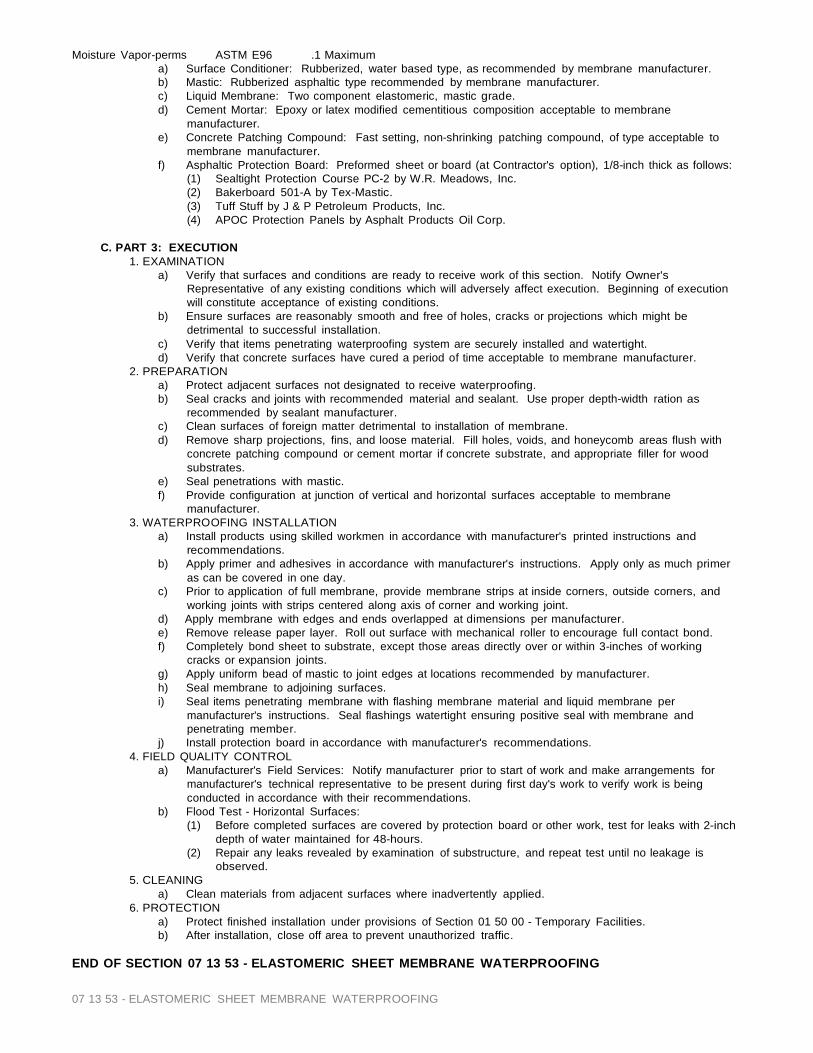
07 13 53 - ELASTOMERIC SHEET MEMBRANE WATERPROOFING
Moisture Vapor-perms ASTM E96 .1 Maximum a) Surface Conditioner: Rubberized, water based type, as recommended by membrane manufacturer. b) Mastic: Rubberized asphaltic type recommended by membrane manufacturer. c) Liquid Membrane: Two component elastomeric, mastic grade. d) Cement Mortar: Epoxy or latex modified cementitious composition acceptable to membrane
manufacturer. e) Concrete Patching Compound: Fast setting, non-shrinking patching compound, of type acceptable to
membrane manufacturer. f) Asphaltic Protection Board: Preformed sheet or board (at Contractor's option), 1/8-inch thick as follows:
(1) Sealtight Protection Course PC-2 by W.R. Meadows, Inc. (2) Bakerboard 501-A by Tex-Mastic. (3) Tuff Stuff by J & P Petroleum Products, Inc. (4) APOC Protection Panels by Asphalt Products Oil Corp.
C. PART 3: EXECUTION
1. EXAMINATION a) Verify that surfaces and conditions are ready to receive work of this section. Notify Owner's
Representative of any existing conditions which will adversely affect execution. Beginning of execution will constitute acceptance of existing conditions.
b) Ensure surfaces are reasonably smooth and free of holes, cracks or projections which might be detrimental to successful installation.
c) Verify that items penetrating waterproofing system are securely installed and watertight. d) Verify that concrete surfaces have cured a period of time acceptable to membrane manufacturer.
2. PREPARATION a) Protect adjacent surfaces not designated to receive waterproofing. b) Seal cracks and joints with recommended material and sealant. Use proper depth-width ration as
recommended by sealant manufacturer. c) Clean surfaces of foreign matter detrimental to installation of membrane. d) Remove sharp projections, fins, and loose material. Fill holes, voids, and honeycomb areas flush with
concrete patching compound or cement mortar if concrete substrate, and appropriate filler for wood substrates.
e) Seal penetrations with mastic. f) Provide configuration at junction of vertical and horizontal surfaces acceptable to membrane
manufacturer. 3. WATERPROOFING INSTALLATION
a) Install products using skilled workmen in accordance with manufacturer's printed instructions and recommendations.
b) Apply primer and adhesives in accordance with manufacturer's instructions. Apply only as much primer as can be covered in one day.
c) Prior to application of full membrane, provide membrane strips at inside corners, outside corners, and working joints with strips centered along axis of corner and working joint.
d) Apply membrane with edges and ends overlapped at dimensions per manufacturer. e) Remove release paper layer. Roll out surface with mechanical roller to encourage full contact bond. f) Completely bond sheet to substrate, except those areas directly over or within 3-inches of working
cracks or expansion joints. g) Apply uniform bead of mastic to joint edges at locations recommended by manufacturer. h) Seal membrane to adjoining surfaces. i) Seal items penetrating membrane with flashing membrane material and liquid membrane per
manufacturer's instructions. Seal flashings watertight ensuring positive seal with membrane and penetrating member.
j) Install protection board in accordance with manufacturer's recommendations. 4. FIELD QUALITY CONTROL
a) Manufacturer's Field Services: Notify manufacturer prior to start of work and make arrangements for manufacturer's technical representative to be present during first day's work to verify work is being conducted in accordance with their recommendations.
b) Flood Test - Horizontal Surfaces: (1) Before completed surfaces are covered by protection board or other work, test for leaks with 2-inch
depth of water maintained for 48-hours. (2) Repair any leaks revealed by examination of substructure, and repeat test until no leakage is
observed. 5. CLEANING
a) Clean materials from adjacent surfaces where inadvertently applied. 6. PROTECTION
a) Protect finished installation under provisions of Section 01 50 00 - Temporary Facilities. b) After installation, close off area to prevent unauthorized traffic.
END OF SECTION 07 13 53 - ELASTOMERIC SHEET MEMBRANE WATERPROOFING

07 14 16 Cold Fluid Applied Waterproofing – Above grade concrete 1
SECTION 07 14 16 - Cold Fluid-Applied Waterproofing – Above grade concrete A. PART I GENERAL
1.01 Scope A. Provide all labor, materials and equipment necessary to apply the Con-Dek ICC ESR-2097 System over horizontal concrete surfaces. This specification includes application over horizontal concrete, which requires waterproofing.
1.02 Related Sections A. Concrete 03 00 00 B. Sealants 07 92 00
1.03 Description A. Con-Dek is a proprietary blend of high performance acrylic formulations. The Con-Dek System is a waterproof barrier with a decorative coating that offers a variety of colors and textures.
1.04 Submittals A. Samples:
1. The applicator shall make and submit a sample of the proposed finish to the architect and/or owner for approval.
B. Manufacturer’s Information: 1. Submit manufacturer’s product information and specifications.
1.05 Quality Assurance A. Qualifications:
1. Manufacturer shall be Pli-Dek Systems, Inc. 2. The applicator shall be listed with Pli-Dek Systems, Inc. as a trained* installer.
B. Substrates 1. Con-Dek should be applied over the following horizontal concrete substrates when prepared in accordance with this specification and Con-Dek Application Instruction PD-175.
A. Concrete on Grade (No vehicle traffic) B. Concrete Decks
2. The applicator*/contractor shall verify that the proposed substrate has been properly prepared in accordance with the Con-Dek Application Instructions, PD-175, before application of the Con-Dek materials.
C. Certifications 1. The Con-Dek System is recognized by the following Model Building Code organizations.
A. ICC- ESR D. Performance Requirements
1. Water Vapor Transmission (ASTM E 96) – Con-Dek should not be applied on surfaces experiencing moisture vapor transmission. 2. Bond Strength (ASTM C 297) 3. Accelerated Aging (ASTM D756) 4. Abrasion Resistance (ASTM D 968) 5. Water Absorption (ASTM D570) 6. Impact Resistance (ASTM D3746 7. Freeze-thaw (ASTM C67) 8. Accelerated Weathering (ASTM G 23) 9. Surface Burning (ASTM E 84) 10. Chemical Resistance (ASTM D2299) 11. Spread of Flame (ASTM E108) 12. Static Coefficient of Friction (ASTM C 1028-96)
1.06 Delivery, Storage and Handling A. All materials shall be delivered to the job site in the original, unopened packages with labels
intact. Upon arrival, materials shall be inspected for physical damage or freezing. Questionable materials shall not be used.
B. Minimum storage temperature shall be 4°C (40°F). Maximum storage temperature shall be 43°C (110°F). All materials shall be stored in a dry location, out of direct sunlight and protected from weather and other damage in accordance with material data safety sheets.
1.07 Job Conditions A. Existing conditions:
1. The applicator shall have access to electrical power, clean potable water and clean work area at the location where the Pli-Dek materials are to be applied. 2. Other working trades need to be made aware to keep off those areas being covered by Pli- Dek materials during the application and curing process. 3. All required inspections must be made prior to the installations of the Pli-Dek materials.
B. Environmental Conditions: 1. The ambient air and surface temperature shall be a minimum of 10°C (50°F) and a maximum of 43°C (110°F) and shall remain so for at least 24 hours.
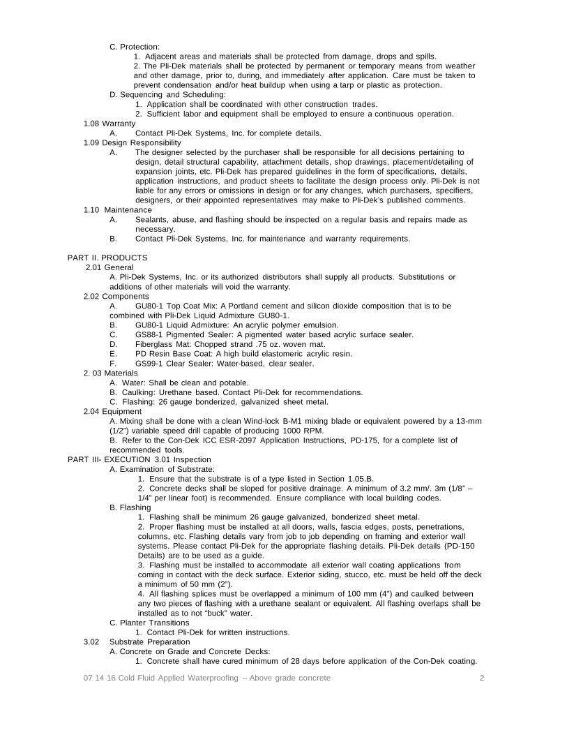
07 14 16 Cold Fluid Applied Waterproofing – Above grade concrete 2
C. Protection: 1. Adjacent areas and materials shall be protected from damage, drops and spills. 2. The Pli-Dek materials shall be protected by permanent or temporary means from weather and other damage, prior to, during, and immediately after application. Care must be taken to prevent condensation and/or heat buildup when using a tarp or plastic as protection.
D. Sequencing and Scheduling: 1. Application shall be coordinated with other construction trades. 2. Sufficient labor and equipment shall be employed to ensure a continuous operation.
1.08 Warranty A. Contact Pli-Dek Systems, Inc. for complete details.
1.09 Design Responsibility A. The designer selected by the purchaser shall be responsible for all decisions pertaining to
design, detail structural capability, attachment details, shop drawings, placement/detailing of expansion joints, etc. Pli-Dek has prepared guidelines in the form of specifications, details, application instructions, and product sheets to facilitate the design process only. Pli-Dek is not liable for any errors or omissions in design or for any changes, which purchasers, specifiers, designers, or their appointed representatives may make to Pli-Dek’s published comments.
1.10 Maintenance A. Sealants, abuse, and flashing should be inspected on a regular basis and repairs made as
necessary. B. Contact Pli-Dek Systems, Inc. for maintenance and warranty requirements.
PART II. PRODUCTS
2.01 General A. Pli-Dek Systems, Inc. or its authorized distributors shall supply all products. Substitutions or additions of other materials will void the warranty.
2.02 Components A. GU80-1 Top Coat Mix: A Portland cement and silicon dioxide composition that is to be combined with Pli-Dek Liquid Admixture GU80-1. B. GU80-1 Liquid Admixture: An acrylic polymer emulsion. C. GS88-1 Pigmented Sealer: A pigmented water based acrylic surface sealer. D. Fiberglass Mat: Chopped strand .75 oz. woven mat. E. PD Resin Base Coat: A high build elastomeric acrylic resin. F. GS99-1 Clear Sealer: Water-based, clear sealer.
2. 03 Materials A. Water: Shall be clean and potable. B. Caulking: Urethane based. Contact Pli-Dek for recommendations. C. Flashing: 26 gauge bonderized, galvanized sheet metal.
2.04 Equipment A. Mixing shall be done with a clean Wind-lock B-M1 mixing blade or equivalent powered by a 13-mm (1/2”) variable speed drill capable of producing 1000 RPM. B. Refer to the Con-Dek ICC ESR-2097 Application Instructions, PD-175, for a complete list of recommended tools.
PART III- EXECUTION 3.01 Inspection A. Examination of Substrate:
1. Ensure that the substrate is of a type listed in Section 1.05.B. 2. Concrete decks shall be sloped for positive drainage. A minimum of 3.2 mm/. 3m (1/8” – 1/4” per linear foot) is recommended. Ensure compliance with local building codes.
B. Flashing 1. Flashing shall be minimum 26 gauge galvanized, bonderized sheet metal. 2. Proper flashing must be installed at all doors, walls, fascia edges, posts, penetrations, columns, etc. Flashing details vary from job to job depending on framing and exterior wall systems. Please contact Pli-Dek for the appropriate flashing details. Pli-Dek details (PD-150 Details) are to be used as a guide. 3. Flashing must be installed to accommodate all exterior wall coating applications from coming in contact with the deck surface. Exterior siding, stucco, etc. must be held off the deck a minimum of 50 mm (2”). 4. All flashing splices must be overlapped a minimum of 100 mm (4”) and caulked between any two pieces of flashing with a urethane sealant or equivalent. All flashing overlaps shall be installed as to not “buck” water.
C. Planter Transitions 1. Contact Pli-Dek for written instructions.
3.02 Substrate Preparation A. Concrete on Grade and Concrete Decks:
1. Concrete shall have cured minimum of 28 days before application of the Con-Dek coating.

07 14 16 Cold Fluid Applied Waterproofing – Above grade concrete 3
2. All undermined, cracked, damaged, etc. concrete must be repaired or replaced before applying the Pli-Dek coatings over the concrete surfaces. All concrete surfaces must be cleaned to remove all grease, oil, moisture, dust, paint, sealers, efflorescence etc. that may impair the adhesion of the Pli-Dek materials. All concrete areas are to be free of moisture, wax, oil, silicone, or solvent curing compounds. Refer to the Con- Dek ICC ESR-2097 Application Instructions, PD-175, for complete information.
E. DEK C-MENT: 1. The DEK C-MENT,manufactured by MaxxEX, shall have a moisture content less than 5% and installed as per published MaxxEx guidelines. 2. All undermined, cracked, damaged, etc. DEK C-MENT must be repaired or replaced before applying the Pli-Dek coatings over the concrete surfaces. 3. The surface must be cleaned as to remove all grease, oil, moisture, dust, paint, sealers, efflorescence etc. that may impair the adhesion of the Pli-Dek materials. All concrete areas are to be free of moisture, wax, oil, silicone, or solvent curing compounds. Refer to the Con-Dek ICC ESR-2097 Application Instructions, PD-175, for complete information. 4. Install a primer and screed coat as per Con-Dek ICC ESR-2097 Application Instructions, PD-175. 5. Refer to MaxxEx for complete sound and fire ratings.
3.03 Application A. General:
1. All concrete surfaces shall be covered with the .75 oz fiberglass Mat and coated the PD Resin Base Coat, refer to the Con-Dek Application Instructions, PD-175, for complete information. B. Primer Coat:
1. Pli-Dek recommends that substrates be ground prior to application to remove contaminates. If you are confident that contaminates are not present, you can proceed with a primer coat. Primer Coat: 1 gallon of GU80 Liquid Admixture to 4 gallons of water. Approximately .02 cents per sq/ft.
C. Screed Coat (Optional): 1. Mix the GU80-1 Liquid Admixture with GU80-1 Top Coat until a uniform consistency is achieved. Refer to Pli- Dek Application Instructions, PD-165 for complete instructions. 2. Apply a Screed coat over the previously applied GU80-1 Base Coat. Allow it to dry completely, for approximately 2 (two) to 6 (six) hours, depending on weather conditions.
D. PD Resin Second Coat: 1. Apply a second coat of PD Resin Base Coat as described in Con-Dek ICC ESR-2097 Application Instructions, PD-175, for complete information. Allow it to dry a minimum of 2 to 6 hours (additional time may be necessary under the adverse drying conditions).
E. Con-Dek Finish Coats: (See Con-Dek ICC ESR-2097 Application Instructions, PD-175, for installation of finish options.)
1. Knockdown Texture Finish 2. Polymer Sand Finish 3. Underlayment System 4. Custom Finish
3.04 Field Quality Control A. The applicator shall be responsible for the proper application of the Con-Dek materials. B. Pli-Dek Systems, Inc. assumes no responsibility for on-site inspections, application, or workmanship.
3.05 Clean Up A. The applicator in accordance with contract provisions shall remove all excess Con-Dek materials from the job site.
F. All surrounding areas, where the Con-Dek materials have been applied, shall be left free of debris and foreign substances resulting from the contractor’s work.
3.06 Slip and Fall Precaution A. OSHA, American Disabilities Act (ADA), and The Federal Housing Act (FHA) have now set enforceable standards for slip-resistance on pedestrian surfaces. Pli-Dek Systems, Inc. recommends the use of angular slip-resistant aggregate in all coatings or flooring systems that may be exposed to wet, oily/greasy, or otherwise potentially slippery conditions. It is the end users responsibility to provide a flooring system that meets current safety standards. Pli- Dek Systems, Inc or its sales agents will not be responsible for injury incurred in a slip and fall accident. Please consult local building codes for the current coefficient of friction requirement.
END OF SECTION 07 14 16 - Cold Fluid-Applied Waterproofing – Above grade concrete

07 14 19 - Cold Fluid-Applied Waterproofing –Plywood Substrates 1
SECTION 07 14 19 - Cold Fluid-Applied Waterproofing –Plywood Substrates A. PART I GENERAL
1.01 Scope A. Provide all labor, materials and equipment necessary to apply the Pli-Dek waterproof system over
horizontal plywood decks, walkways, and stairs. 1.02 Related Sections
A. Sealants 07 92 00 : Vulkem 931 caulking or equivalent. 1.03 References
A. ASTM C 297: Test Method for Bond Strength of Flat Sandwich Constructions in a Flat Wise Plane B. ASTM D570: Test Method for Water Absorption of Plastics C. ASTM D1242: Test Method for Resistance of Plastic Materials to Abrasion D. ASTM E 96: Tests Method for Water Vapor Transmission of Materials E. ASTM E 108: Method for Fire Tests of Roof Coverings F. ASTM G 23: Test Method for Weatherablity G. ASTM D2707L: Test Method for Tensile Strength – Longitude H. ASTM D270T: Test Method for Tensile Strength – Transverse I. ASTM A756: Test Method for Freeze-Thaw Cycle for deleterious effects J. ASTM C67: Test Method for Freeze-Thaw Cycle for weight loss K. ASTM C150-72: Test Method for Compressive Strength L. ASTM D2299: Test Method for Chemical Resistance M. ASTM C1028-96: Test Method for Static Coefficient of Friction N. ASTM E108: Test Method for Spread of Flame O. ASTM E108: Test Method for Intermittent Flame P. ASTM E119: Test Method for One-Hour System Q. ASTM Pending: Test Method for Impact R. ASTM Pending: Test Method for Concentrated Load S. ASTM Pending: Test Method for Percolation
1.04 Description A. Pli-Dek is a proprietary blend of high performance acrylic formulations. Pli-Dek is a waterproofing system providing a durable walking surface in a variety of textures, finishes, and colors.
1.05 Submittals A. Samples:
1. The Pli-Dek Applicator shall make and submit samples of the proposed finish to the architect and/or owner for approval.
B. Manufacturer’s Information: 1. Submit manufacturer’s product information and specifications.
1.06 QUALITY ASSURANCE A. Qualification:
1. Manufacturer shall be Pli-Dek Systems, Inc. 2. The applicator shall be listed with Pli-Dek Systems, Inc. as a trained* installer.
B. Substrates: 1. The Pli-Dek system installs over a minimum 16 mm, 5/8’’ (3/4” recommended) sound and dry, exterior grade sheeting; installed in accordance with this specification and Pli-Dek Application Instructions, PD165. 2. The applicator/contractor shall verify that the proposed substrate is acceptable prior to application of the Pli- Dek System. Contact Pli-Dek Systems, Inc. for applications over Oriented Strand Board (OSB).
C. Certifications: 1. The Pli-Dek System is recognized by the following Model Building Code organizations:
A. ICC-ES D. Performance Requirements:
1. Water Vapor Transmission (ASTM E 96) 2. Bond Strength (ASTM C 297) 3. Abrasion Test (ASTM D 968) 4. Weatherability Test (ASTM G 23) 5. Class A Burn Tests (ASTM E 108) 6. Freeze-Thaw Cycling (ASTM A75) 7. Compressive Strength (ASTM C150-72) 8. Water Absorption (ASTM D570) 9. Chemical Resistance (ASTM D2299) 10. Static Coefficient of Friction (ASTM C 1028-96) 11. One-Hour System (ASTM E119) 12. Wind-Up Lift (Factory Mutual 1.52)
1.07 Delivery, Storage and Handling A. All materials shall be delivered to the job site in the original, unopened packages with labels intact.
Upon arrival, materials shall be inspected for physical damage or freezing. Questionable materials
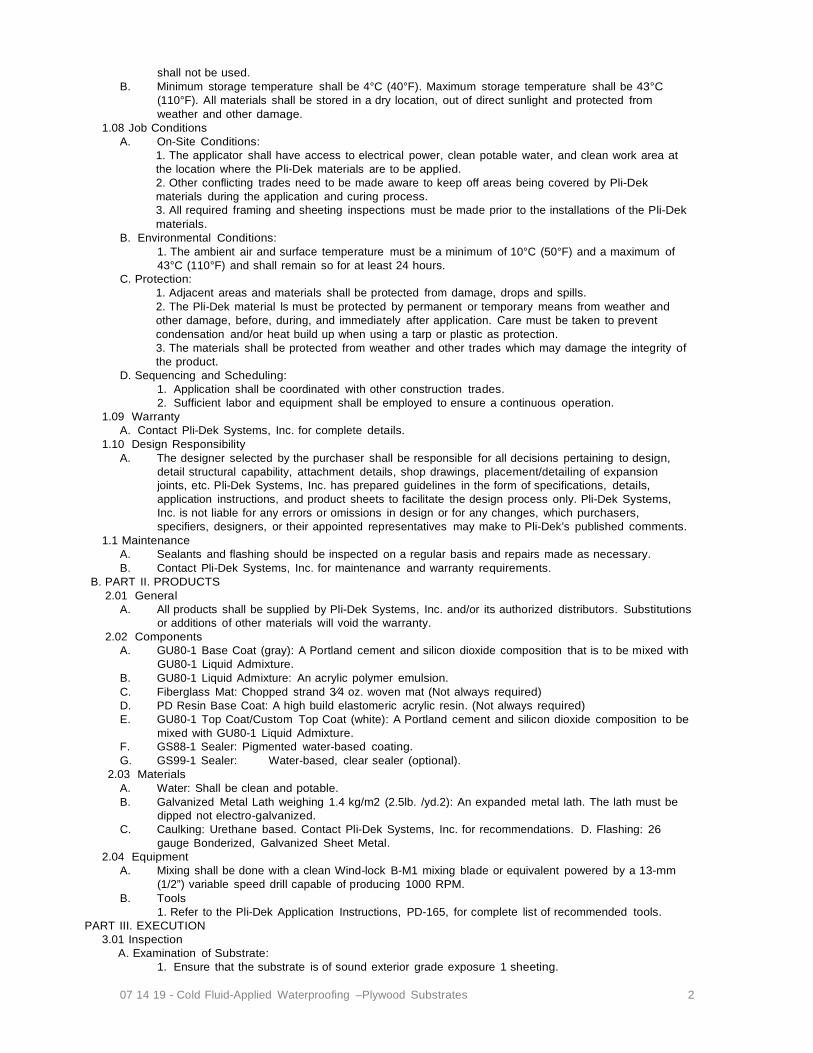
07 14 19 - Cold Fluid-Applied Waterproofing –Plywood Substrates 2
shall not be used. B. Minimum storage temperature shall be 4°C (40°F). Maximum storage temperature shall be 43°C
(110°F). All materials shall be stored in a dry location, out of direct sunlight and protected from weather and other damage.
1.08 Job Conditions A. On-Site Conditions:
1. The applicator shall have access to electrical power, clean potable water, and clean work area at the location where the Pli-Dek materials are to be applied. 2. Other conflicting trades need to be made aware to keep off areas being covered by Pli-Dek materials during the application and curing process. 3. All required framing and sheeting inspections must be made prior to the installations of the Pli-Dek materials.
B. Environmental Conditions: 1. The ambient air and surface temperature must be a minimum of 10°C (50°F) and a maximum of 43°C (110°F) and shall remain so for at least 24 hours.
C. Protection: 1. Adjacent areas and materials shall be protected from damage, drops and spills. 2. The Pli-Dek material ls must be protected by permanent or temporary means from weather and other damage, before, during, and immediately after application. Care must be taken to prevent condensation and/or heat build up when using a tarp or plastic as protection. 3. The materials shall be protected from weather and other trades which may damage the integrity of the product.
D. Sequencing and Scheduling: 1. Application shall be coordinated with other construction trades. 2. Sufficient labor and equipment shall be employed to ensure a continuous operation.
1.09 Warranty A. Contact Pli-Dek Systems, Inc. for complete details.
1.10 Design Responsibility A. The designer selected by the purchaser shall be responsible for all decisions pertaining to design,
detail structural capability, attachment details, shop drawings, placement/detailing of expansion joints, etc. Pli-Dek Systems, Inc. has prepared guidelines in the form of specifications, details, application instructions, and product sheets to facilitate the design process only. Pli-Dek Systems, Inc. is not liable for any errors or omissions in design or for any changes, which purchasers, specifiers, designers, or their appointed representatives may make to Pli-Dek’s published comments.
1.1 Maintenance A. Sealants and flashing should be inspected on a regular basis and repairs made as necessary. B. Contact Pli-Dek Systems, Inc. for maintenance and warranty requirements.
B. PART II. PRODUCTS 2.01 General
A. All products shall be supplied by Pli-Dek Systems, Inc. and/or its authorized distributors. Substitutions or additions of other materials will void the warranty.
2.02 Components A. GU80-1 Base Coat (gray): A Portland cement and silicon dioxide composition that is to be mixed with
GU80-1 Liquid Admixture. B. GU80-1 Liquid Admixture: An acrylic polymer emulsion. C. Fiberglass Mat: Chopped strand 3⁄4 oz. woven mat (Not always required) D. PD Resin Base Coat: A high build elastomeric acrylic resin. (Not always required) E. GU80-1 Top Coat/Custom Top Coat (white): A Portland cement and silicon dioxide composition to be
mixed with GU80-1 Liquid Admixture. F. GS88-1 Sealer: Pigmented water-based coating. G. GS99-1 Sealer: Water-based, clear sealer (optional).
2.03 Materials A. Water: Shall be clean and potable. B. Galvanized Metal Lath weighing 1.4 kg/m2 (2.5lb. /yd.2): An expanded metal lath. The lath must be
dipped not electro-galvanized. C. Caulking: Urethane based. Contact Pli-Dek Systems, Inc. for recommendations. D. Flashing: 26
gauge Bonderized, Galvanized Sheet Metal. 2.04 Equipment
A. Mixing shall be done with a clean Wind-lock B-M1 mixing blade or equivalent powered by a 13-mm (1/2”) variable speed drill capable of producing 1000 RPM.
B. Tools 1. Refer to the Pli-Dek Application Instructions, PD-165, for complete list of recommended tools.
PART III. EXECUTION 3.01 Inspection
A. Examination of Substrate: 1. Ensure that the substrate is of sound exterior grade exposure 1 sheeting.

07 14 19 - Cold Fluid-Applied Waterproofing –Plywood Substrates 3
2. Refer to ICC-ES Legacy Report for framing requirements. 3. All surfaces shall be sloped for positive drainage. A slope of 6.4 mm/.3m (1/4” per linear foot) is required. 4. All plywood seams shall be staggered and a 3.2 mm (1/8”) space between all sheets shall exist. 5. Framing or blocking must support all plywood edges, except as per APA guidelines, blocking is not required when tongue and groove plywood is used. Joists to be spaced 16” on center. For alternate assemblies contact Pli-Dek Systems, Inc. for written approval. 6. Maximum deflection of the deck shall not exceed L/360th of the span. 7. Minimum thickness of plywood shall be 16 mm (5/8”). 3/4” thick exposure 1 sheeting recommended. 8. All adjacent edges of the plywood sheets shall not be more than 0.78 mm (1/32”) out of plane (i.e.: above or below each other).
B. Flashing: 1. Flashing shall be minimum 26 gauge galvanized, bonderized sheet metal. 2. When copper flashing/drains are used, ensure that all galvanized metal; such as, nails, staples, lath, drains, etc. does not come into contact with copper (do not allow any dissimilar metals to come in contact with each other). The contact of the two dissimilar metals cause will create rust and corrosion (electrolysis). **Contact Pli-Dek Systems, Inc. for additional details and written recommendations. 3. Proper flashing must be installed at all doors, walls, fascia edges, posts, penetrations, columns, etc. See Pli- Dek Details for further instructions (PD-150 Architectural Details). Contact Pli-Dek for written approval on flashing details that vary or are not included in PD-150 Architectural Details. 4. Flashing must be installed to accommodate all exterior wall coating applications from coming in contact with the deck surface. Exterior siding, stucco, etc. must be held off the deck a minimum of 50 mm (2”). 5. All flashing splices must be overlapped a minimum of 100 mm (4”) and caulked between any two pieces of flashing with a Vulkem 931 Urethane sealant or equivalent. All flashing overlaps shall be installed as to not “buck” water. 6. Flashing at walls must be installed behind the building paper (or equivalent) on all areas that intersect the deck surface.
3.02 Substrate Preparation A. Plywood Deck:
1. All seams in plywood shall be gapped 3.2 mm (1/8”), and covered with a maximum of 50 mm (2”) wide Pli-Dek approved flashing paper and tacked in place. 2. Plywood shall be free of dust, moisture, and/or other debris or residue that would affect adhesion. 3. Delaminated plywood shall be replaced with sound plywood. 4. Fascia boards shall be installed to be level with the plywood substrate. 5. Perimeter walls should be framed so to be consistent with interior floor boundaries.
3.03 Application A. General:
1. Refer to the Pli-Dek Application Instructions, PD-165, for complete information. B. Base Coat:
1. Mix the GU80-1 Liquid Admixture with GU80-1 Base Coat. Refer to Pli-Dek Application Instructions, PD-165 for complete instructions. 2. Trowel Base Coat emulsion into the galvanized expanded metal lath completely covering the metal lath. Allow it to dry completely, for approximately 2 (two) to 6 (six) hours, depending on weather conditions.
C. Screed Coat: 1. Mix the GU80-1 Liquid Admixture with GU80-1 Top Coat until a uniform consistency is achieved. Refer to Pli- Dek Application Instructions, PD-165 for complete instructions. 2. Apply a Screed coat over the previously applied GU80-1 Base Coat. Allow it to dry completely, for approximately 2 (two) to 6 (six) hours, depending on weather conditions.
D. Pli-Dek “F” System (Fiberglass and Resin Coat): 1. **This application becomes required when job conditions may experience excessive movement. Example: cantilevered decks, large spanning decks, etc. Contact Pli-Dek Systems. Inc. for written recommendations. Some geographic locations may require the Fiberglass and Resin Coating in ALL applications. Contact Pli-Dek for written verification. 2. Lay out the .75 oz fiberglass mat over entire deck and apply the PD Resin Base Coat.
E. Pli-Dek Finish Options / Specification Reference: (See Pli-Dek Application Instructions, PD165) 1. Pli-Dek “K” System – Knockdown Texture Finish 2. Pli-Dek “B” System – Elastomeric Sand Finish 3. Pli-Dek “C” System – Polyacrylic Sand Finish 4. Pli-Dek “S” System – Polyacrylic Smooth Finish 5. Pli-Dek “T” System – Epoxy Stone Finish 6. Pli-Dek “Custom Finish” – Simulated Finish 7. Pli-Dek “U” System – Underlayment for Tile or Concrete

07 14 19 - Cold Fluid-Applied Waterproofing –Plywood Substrates 4
8. Pli-Dek “F” System – Fiberglass & Resin Reinforcement 3.04 FieldQualityControl
A. The applicator shall be responsible for the proper application of the Pli-Dek materials. B. Pli-Dek Systems, Inc. assumes no responsibility for on-site inspections, application or workmanship.
3.05 Clean-Up A. All excess Pli-Dek materials shall be removed from the job site by the contractor in accordance with
contract provisions. B. All surrounding areas, where the Pli-Dek materials have been applied, shall be left free of debris and
foreign substances resulting from the contractor’s work. 3.06 Slip and Fall Precaution
A. OSHA, American Disabilities Act (ADA), and The Federal Housing Act (FHA) have now set enforceable standards for slip-resistance on pedestrian surfaces. Pli-Dek Systems, Inc. recommends the use of angular slip-resistant aggregate in all coatings or flooring systems that may be exposed to wet, oily/greasy, or otherwise potentially slippery conditions. It is the end users responsibility to provide a flooring system that meets current safety standards. Pli-Dek Systems, Inc or its sales agents will not be responsible for injury incurred in a slip and fall accident. Please consult local building codes for the current coefficient of friction requirement.
II. END of SECTION 07 14 19 - Cold Fluid-Applied Waterproofing –Plywood Substrates

SECTION 07 21 00 - THERMAL INSULATION
A. PART 1 GENERAL 1. RELATED DOCUMENTS
a) Provisions established within the General and Supplementary General Conditions of the Contract, Division 1 - General Requirements, and the Drawings are collectively applicable to this Section.
b) Section 03 30 00: Cast-in-Place Concrete c) Section 06 10 0: Rough Carpentry d) Section 06 17 53: Wood Trusses e) Section 09 20 00: Gypsum Board Systems f) Section 07 06 80 - Fire Stopping
2. REFERENCES a) Standards of the Following as Referenced
(1) American Society for Testing and Materials (ASTM) (2) Federal Specifications (Fed. Spec.) (3) The Society of the Plastics Industry, Inc. (SPI) (4) Underwriters' Laboratories, Inc. (UL)
3. SECTION INCLUDES a) Batt Insulation b) blown-in loose fill insulation with vapor barrior
4. SUBMITTALS a) Submit manufacturer's certificate under provisions of Section 01 45 00 - Quality Control, that
products meet or exceed specified requirements. 5. DELIVERY, STORAGE, AND HANDLING
a) Comply with manufacturer's product data for handling and storage.
B. PART 2 PRODUCTS 1. MATERIALS
a) Batt Insulation (1) Manufacturer: Any (2) Product: Glass fiber composition (3) Thickness: As specified on plans to meet local code requirements and energy
calculations.
A. PART 3 EXECUTION 1. INSPECTION
a) Verify that surfaces are clean, dry, and free of matter that may inhibit insulation adhesion. b) Verify other work on and within spaces to be insulated is complete prior to insulation
application. c) Beginning installation means acceptance of substrate and project conditions.
2. BATT INSTALLATION a) General: Comply with manufacturer's product data for each type installation. Cut insulation
around obstructions and protrusions. Remove projections interfering with installation. b) Thermal Insulation Installation
(1) General: Comply with manufacturer's installation instructions for conditions encountered. (2) Batt insulation
(a) Install in indicated exterior walls and ceiling areas with vapor barrier to building interior. Attach flanges to wood framing with staples.
3. BLOWN-IN INSTALLATION a) General: Comply with manufacturer's product data for each type installation. Net all areas and
blow in evenly into all cavities. Provide a vapor barrier. b) Thermal Insulation Installation
(1) General: Comply with manufacturer's installation instructions for conditions encountered. (2) Blown-In insulation
(a) Install in indicated exterior walls and ceiling areas with vapor barrier to building interior. 4. FIELD QUALITY CONTROL
a) Provide certification that insulation has been installed per the requirements of this section and the plan and code listing per value. Certification shall be signed by the principle of the insulation Subcontractor and the General Contractor.
END OF SECTION 07 21 00 - THERMAL INSULATION
07 21 00 - THERMAL INSULATION

07 21 13 - Building Insulation (rigid)
Section 07 21 13 - BUILDING INSULATION
Part I - GENERAL
1.01 SCOPE OF WORK
A. The Contractor shaII provide all labor, materials, tools and equipment required to furnish and install thermal insulation in exterior walls and ceilings, blanket acoustical insulation in interior partitions and rigid perimeter insulation, as described in this section and as shown on the Contract Drawings.
1.02 SUBMITIALS
A. The Contractor shall provide descriptive submittals in accordance with the provisions of Section 01001 of these Specifications. Submittals include, but are not limited to, the following:
1. Catalog data, manufacturers and other data needed to prove compliance with the requirements of the section and the referenced documents.
2. Manufacturers recommended method of installation.
1.03 QUALITY ASSURANCE
Thickness indicated is for thermal conductivity (k value at 75 degrees F) specified for each material. Provide adjusted thickness for equivalent materials having a different thermal conductivity. Provide thickness required to achieve indicated "R" value when so specified.
Part 2 - PRODUCTS
2.01 MATERIALS
A. Batt Insulation: Preformed mineral wool: 1.0 perm waterproof paper backed with flanges with thermal insulation conforming to ASTM C-665, Type II, Class C. B. Acoustical Insulation: Paperless, semi-rigid spun mineral fiber mat conforming to ASTM C-665, Type 1. Density: 3 or 41b./cf (48 or 64 kg/m3). C. Perimeter Insulation: Rigid, closed cell, extruded, foamed polystyrene insulation boards; FS HH-I-524C, Type I, Class A, 1 lb/cf(16 kgfm3) average density, U .26 per inch. D. Rigid Insulation: Extruded polystyrene, R-value 5.0 per inch, compressive strength 25 psi, and water absorption 0.1. E. Accessories: Adhesive and fasteners as required.
Part 3 - EXECUTION
3.01 PREPARATION
A. The Contractor shall verify that the work ofother trades is complete to the point where this installation may properly commence, and that adjacent materials are dry and ready to receive the insulation. B. The Contractor shall verify that mechanical and electrical services with wall are installed and tested before installing the insulation.
3.02 INSTALLATION
A. Install insulation after mechanical and electrical services within walls have been installed. Fit insulation tight within spaces and tight to and behind mechanical and electrical services. Leave no gaps or voids. B. Install batt insulation with factory applied membrane facing warm side of building spaces. Lap ends and side flanges of membrane over framing members. Tape seal butt ends and lapped side flanges and ends. Do not tear or cut membrane. C. Install batt insulation in ceiling spaces. Support adequately utilizing wire lattice supported from framing members. D. Install acoustical insulation tight to framing members. Install behind electrical and mechanical services. Provide continuous within spaces as required. E. Apply rigid polystyrene insulation to vertical surfaces or perimeter foundation walls in accordance with manufacturer's instructions. Use type of adhesive recommended. Adhere boards to foundation perimeter, horizontally. Place boards in a method to maximize contact bedding. Stagger joints. Butt edges and ends tight to adjacent boards and to protrusions. END OF SECTION

SECTION 07 21 29 SPRAY BUILDING INSULATION
SECTION 07 21 29 SPRAY BUILDING INSULATION PART 1 GENERAL 1.1 SECTION INCLUDES
A. Polyicynene spray insulation. 1.2 RELATED SECTIONS
A. Section 06 10 00 - Rough Carpentry. B. Section 07 26 00 - Vapor Retarders. C. Section 07 92 00 - Joint Sealants.
1.3 REFERENCES
A. American Society for Testing and Materials (ASTM): 1. ASTM C518, Test Method for Steady State Heat Flux Measurements and Thermal
Transmission Properties by Means of the Heat Flow Meter Apparatus. 2. ASTM 02863, Test Method for Measuring the Minimum Oxygen Concentration to Support
Candlelike Combustion of Plastics (Oxygen Index). 3. ASTIVI E84, Test Method for Surface Burning Characteristics of Building Materials. 4. ASTM E90 , Test Method for Laboratory Measurement of Airborne Sound Transmission
Loss of Building Partitions. 5. ASTM E96, Test Methods for Water Vapor Transmission Rate of Building Materials. 6. ASTM E283, Test Method for Determining the Rate of Air Leakage Walls, and Doors
Under Specified Differences Across the Specimenl 7. ASTM E2178, Standard Test Method for Air Permeance of Building Materials.
1.4 SUBMITTALS
A. Submit under provisions of Section 01 30 00. B. Product Data: Manufacturer's data sheets on each product to be used, including:
1. Preparation instructions and recommendations. 2. Storage and handling requirements and recommendations. 3. Test data showing compliance of products with specified requirements. 4. Installation methods.
C. LEED Documentation: Indicate percentage of waste materials by weight diverted from landfill and recycled. D. Certifications:
1. Submit manufacturer's certificate that products meet or exceed specified requirements. 2. Submit installer qualifications.
1.5 QUALITY ASSURANCE
A. Manufacturer Qualifications: Company with minimum three years experience manufacturing specified products. B. Installer Qualifications: Utilize an installer having demonstrated experience on projects of similar size and complexity, and trained by the manufacturer. C. Mock-Up:
1. Construct mock-up, 4 feet long by 4 feet wide, including substrate construction. 2. Locate where directed. 3. If approved by Architect, mock-up may remain as part of the Work.
1.6 REGULATORY REQUIREMENTS
A. Conform to applicable code requirements for flame and smoke ratings and non-combustibility as applicable.
1.7 ENVIRONMENTAL REQUIREMENTS
A. Toxicity/Hazardous Materials: 1. Formaldehyde: Products containing urea-formaldehyde shall not be permitted. 2. Chlorofluorocarbons (CFCs)/HCFCs: Products and equipment requiring or using CFCs or
HCFCs during the manufacturing process shall not be permitted. B. Air-tightness: Install to meet requirements of the Energy Star Program of 1.5 Air Changes/Hour at 50 Pa and a maximum air permeance of 0.02 Lls-m2 at 75 Pa as per ASTM E 283 or ASTM E 2178.
1.8 DELIVERY, STORAGE, AND HANDLING
A. Store products in manufacturer's unopened packaging until ready for installation. B. Store products in protected area not exposed to weather and at temperature conditions recommended by manufacturer.

SECTION 07 21 29 SPRAY BUILDING INSULATION
1.9 PROJECT CONDITIONS A. Maintain environmental conditions (temperature, humidity, and ventilation) within limits recommended by manufacturer for optimum results. Do not install products under environmental conditions outside manufacturer's absolute limits.
PART 2 PRODUCTS 2.1 MANUFACTURERS
A. Acceptable Manufacturer: Icynene Inc., which is located at: 6747 Campobello Rd. Mississauga, ON, Canada L5N 2L7; Toll Free Tel: 800-758-7325; Tel: 905-3634040; Fax: 905-363-0102; Email: [email protected]; Web: www.icynene.com B. Requests for substitutions will be considered in accordance with provisions of Section 01600.
2.2 MATERIALS
A. Polyicynene Spray Insulation: Icynene; hydrophobic, low-density, open-cell modified polyicynene; conforming to the following:
1. Thermal Resistance (R-Value/inch): ASTM C518; 3.6 hrlsq ftldegree F/BTU. (RSI 0.62 hr/m2/degree C/W).
2. Air Permeance: ASTM E283; 0.0049 I/m2/second for 5.25 inches(133 mm) of material.
3. Water Vapor Transmission: ASTM E96; 10 perms for 5 inches (127 mm) of material. 4. Sound Transmission Class (STC): ASTM E90; STC 37 in wood stud wall. 5. Noise Reduction Coefficient (NRC): ASTM E90; NRC-0.7 in wood stud wall. 6. Corrosion: No significant corrosion when in contact with steel under 85 percent
relative humidity and 118 degrees F. 7. Bacterial or Fungal Growth: No growth; no material deterioration. 8. Flame Spread and Smoke Developed Rating: ASTM E84; <201<400. 9. Fuel Contribution: ASTM E84; O. 10. Oxygen Index: ASTM 02863; average value 23.1 percent.
PART 3 EXECUTION 3.1 EXAMINATION
A. Do not begin installation until substrates have been properly prepared. B. Verify that substrate and cavities are free of any foreign material that will impede application. C. Verify that other work on and within spaces to be insulated is complete prior to application. D. If substrate preparation is the responsibility of another installer, notify Architect of unsatisfactory preparation before proceeding.
3.2 PREPARATION
A. Prepare surfaces using the methods recommended by the manufacturer for achieving the best result for the substrate under the project conditions. B. Remove foreign materials, dirt, grease, oil, paint, laitance, efflorescence, and other substances that will affect application. C. Mask and protect adjacent surfaces from overs pray or damage.
3.3 APPLICATION
A. Apply insulation in accordance with manufacturer's written application instructions. Apply insulation to a uniform density without voids. B. Apply to minimum cured thickness as indicated on the Drawings or as scheduled at the end of this Section. C. Apply to minimum cured thickness as scheduled on Drawings. D. Apply insulation to fill voids around doors and windows. Apply insulation to fill voids around accessible service and equipment penetrations. E. Apply insulation to seal voids at truss ends to prevent wind scouring of ceiling insulation. F. Seal plumbing stacks, electrical wiring and other penetrations into attic to control air leakage. G. Apply insulation to fill voids around bathtubs to point of accessibility. H. Apply insulation in unvented roof spaces and cathedral ceiling areas. I. Where building is designed to meet the specific airtightness standards of the Energy Star Program, apply insulation as recommended by manufacturer to provide airtight construction. Apply sealant to jOints between structural assemblies as specified in Division 7.
3.4 FIELD QUALITY CONTROL
A. Inspect application for insulation thickness and density.

SECTION 07 21 29 SPRAY BUILDING INSULATION
3.5 PROTECTION
A. Do not permit subsequent work to disturb applied insulation. B. Touch-up, repair or replace damaged products before Substantial Completion.
3.6 CONSTRUCTION WASTE MANAGEMENT
A. Plan and coordinate the insulation work to minimize the generation of offcuts and waste. Reuse insulation scraps to the maximum extent feasible. B. Separate and recycle waste materials in accordance with the Waste Management Plan and to the extent economically feasible.
END OF SECTION

07 54 23 THERMOPLASTIC-POLYOLEFIN ROOFING 1
SECTION 07 54 23 – THERMOPLASTIC-POLYOLEFIN ROOFING
PART 1 - GENERAL
1.1 RELATED DOCUMENTS
A. Drawings and general provisions of the Contract, including General and Supplementary Conditions and Division 01 Specification Sections, apply to this Section.
1.2 SUMMARY
A. This Section includes the following:
1. Adhered membrane roofing system. 2. Cover board. 3. Roof insulation. 4. Base sheet. 5. Sheathing paper. 6. Substrate board.
B. Related Sections include the following:
1. Division 06 Section Rough Carpentry for wood nailers, curbs, and blocking and for wood-based,
structural-use roof deck panels. 2. Division 07 Section "Thermal Insulation" for insulation beneath the roof deck. 3. Division 07 Section "Sheet Metal Flashing and Trim" for metal roof penetration flashings, flashings,
and counterflashings. 4. Division 07 Section "Manufactured Roof Expansion Joints." 5. Division 07 Section "Joint Sealants." 6. Division 22 Section "Storm Drainage Piping Specialties" for roof drains.
C. Unit Prices: Refer to Division 01 Section "Unit Prices" for description of Work in this Section affected by
unit prices.
1.3 DEFINITIONS
A. Roofing Terminology: Refer to ASTM D 1079 “Terminology Relating to Roofing and Waterproofing”; glossary of NRCA's "The NRCA Roofing and Waterproofing Manual"; and the Roof Consultants Institute “Glossary of Roofing Terms” for definition of terms related to roofing work in this Section.
B. Sheet Metal Terminology and Techniques: SMACNA Architectural Sheet Metal Manual.
1.4 PERFORMANCE REQUIREMENTS
A. General: Provide installed roofing membrane and Flashings that remain watertight; do not permit the passage of water; and resist specified uplift pressures, thermally induced movement, and exposure to weather without failure.
B. Material Compatibility: Provide roofing materials that are compatible with one another under conditions of
service and application required, as demonstrated by roofing membrane manufacturer based on testing and field experience.
C. Jobsite Safety: Execute all operations and provide a safe work environment in accordance to OSHA standards and regulations. This requirement applies to all contractor personnel, associated subcontractors, workers in other trades, and jobsite visitors.
1. Follow all industry fire prevention guidelines for storage of materials, staging areas, roof access,
and application means and methods. 2. Any applicable local fire codes supersede industry guidelines.
D. Roofing System Design: Provide a membrane roofing system that is identical to systems that have been
successfully tested by a qualified testing and inspecting agency to resist uplift pressure calculated according to ASCE 7.
1. Corner Uplift Pressure: <Insert number> lbf/sq. ft. 2. Perimeter Uplift Pressure: <Insert number> lbf/sq. ft 3. Field-of-Roof Uplift Pressure: <Insert number> lbf/sq. ft 4. Retain paragraph and subparagraphs below if Project is FMG (Factory Mutual Global) insured or if
using FMG requirements as quality standard.
5. Provide system complying to RoofNav #: 6. Fire/Windstorm Classification: Class 1A-[60] [75] [90] [105] [120 7. Hail Resistance: [MH] [SH].
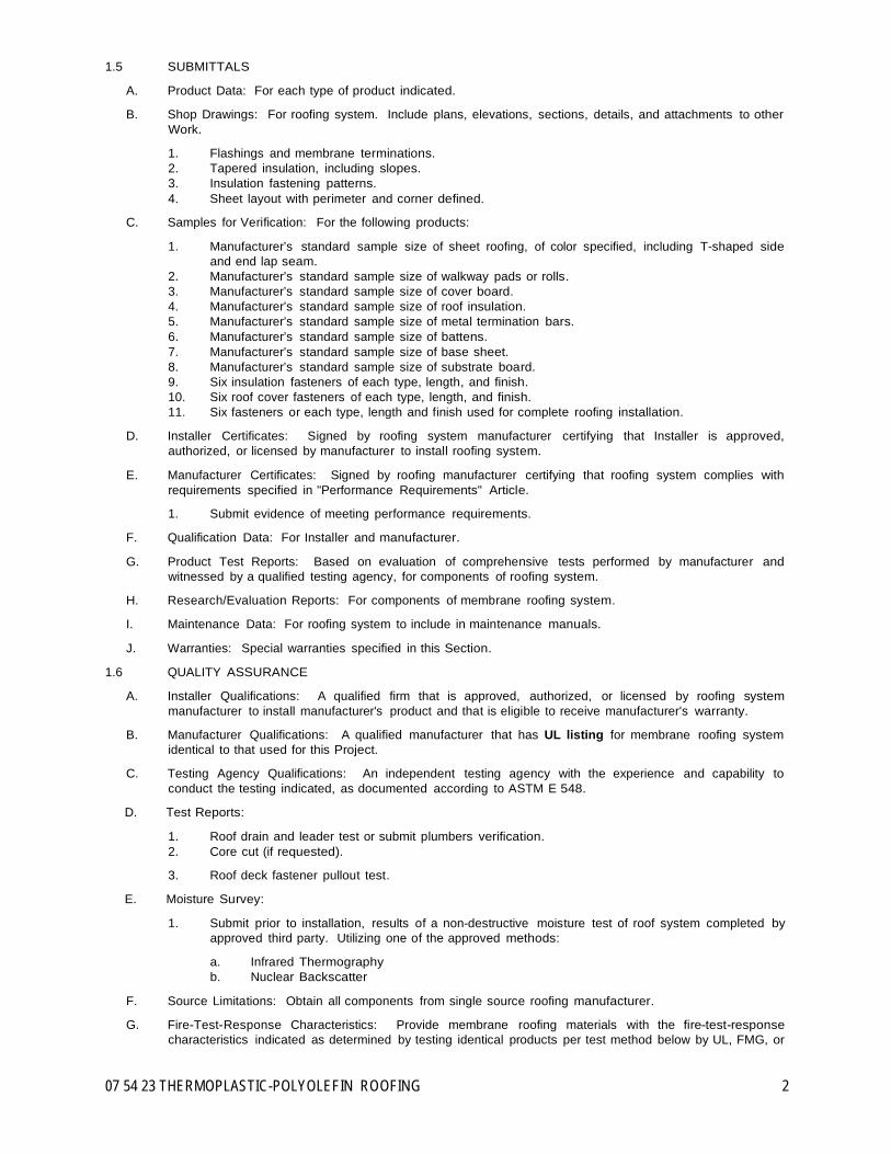
07 54 23 THERMOPLASTIC-POLYOLEFIN ROOFING 2
1.5 SUBMITTALS
A. Product Data: For each type of product indicated.
B. Shop Drawings: For roofing system. Include plans, elevations, sections, details, and attachments to other Work.
1. Flashings and membrane terminations. 2. Tapered insulation, including slopes. 3. Insulation fastening patterns. 4. Sheet layout with perimeter and corner defined.
C. Samples for Verification: For the following products:
1. Manufacturer’s standard sample size of sheet roofing, of color specified, including T-shaped side and end lap seam.
2. Manufacturer’s standard sample size of walkway pads or rolls. 3. Manufacturer’s standard sample size of cover board. 4. Manufacturer’s standard sample size of roof insulation. 5. Manufacturer’s standard sample size of metal termination bars. 6. Manufacturer’s standard sample size of battens. 7. Manufacturer’s standard sample size of base sheet. 8. Manufacturer’s standard sample size of substrate board. 9. Six insulation fasteners of each type, length, and finish. 10. Six roof cover fasteners of each type, length, and finish. 11. Six fasteners or each type, length and finish used for complete roofing installation.
D. Installer Certificates: Signed by roofing system manufacturer certifying that Installer is approved,
authorized, or licensed by manufacturer to install roofing system.
E. Manufacturer Certificates: Signed by roofing manufacturer certifying that roofing system complies with requirements specified in "Performance Requirements" Article.
1. Submit evidence of meeting performance requirements.
F. Qualification Data: For Installer and manufacturer.
G. Product Test Reports: Based on evaluation of comprehensive tests performed by manufacturer and witnessed by a qualified testing agency, for components of roofing system.
H. Research/Evaluation Reports: For components of membrane roofing system.
I. Maintenance Data: For roofing system to include in maintenance manuals.
J. Warranties: Special warranties specified in this Section.
1.6 QUALITY ASSURANCE
A. Installer Qualifications: A qualified firm that is approved, authorized, or licensed by roofing system manufacturer to install manufacturer's product and that is eligible to receive manufacturer's warranty.
B. Manufacturer Qualifications: A qualified manufacturer that has UL listing for membrane roofing system
identical to that used for this Project.
C. Testing Agency Qualifications: An independent testing agency with the experience and capability to conduct the testing indicated, as documented according to ASTM E 548.
D. Test Reports:
1. Roof drain and leader test or submit plumbers verification. 2. Core cut (if requested).
3. Roof deck fastener pullout test.
E. Moisture Survey:
1. Submit prior to installation, results of a non-destructive moisture test of roof system completed by approved third party. Utilizing one of the approved methods:
a. Infrared Thermography b. Nuclear Backscatter
F. Source Limitations: Obtain all components from single source roofing manufacturer.
G. Fire-Test-Response Characteristics: Provide membrane roofing materials with the fire-test-response
characteristics indicated as determined by testing identical products per test method below by UL, FMG, or

07 54 23 THERMOPLASTIC-POLYOLEFIN ROOFING 3
another testing and inspecting agency acceptable to authorities having jurisdiction. Materials shall be identified with appropriate markings of applicable testing and inspecting agency.
1. Exterior Fire-Test Exposure: Class A; ASTM E 108, for application and roof slopes indicated. 2. Fire-Resistance Ratings: ASTM E 119, for fire-resistance-rated roof assemblies of which roofing
system is a part.
H. Preliminary Roofing Conference: Before starting roof deck construction, conduct conference at Project site. Comply with requirements for preinstallation conferences in Division 01 Section "Project Management and Coordination." Review methods and procedures related to roof deck construction and roofing system including, but not limited to, the following:
1. Meet with Owner, Architect, Owner's insurer if applicable, testing and inspecting agency representative, roofing Installer, roofing system manufacturer's representative, deck Installer, and installers whose work interfaces with or affects roofing including installers of roof accessories and roof-mounted equipment.
2. Review methods and procedures related to roofing installation, including manufacturer's written instructions.
3. Review and finalize construction schedule and verify availability of materials, Installer's personnel, equipment, and facilities needed to make progress and avoid delays.
4. Examine deck substrate conditions and finishes for compliance with requirements, including flatness and fastening.
5. Review structural loading limitations of roof deck during and after roofing. 6. Require that all complimentary trades be present at conference. Including, but not limited to;
electrical, plumbing, HVAC, and framing contractors. 7. Review Flashings, special roofing details, roof drainage, roof penetrations, equipment curbs, and
condition of other construction that will affect roofing system. 8. Review governing regulations and requirements for insurance and certificates if applicable. 9. Review temporary protection requirements for roofing system during and after installation. 10. Review roof observation and repair procedures after roofing installation.
I. Preinstallation Conference: Conduct conference at Project site. Comply with requirements in Division 01
Section "Project Management and Coordination." Review methods and procedures related to roofing system including, but not limited to, the following:
1. Meet with Owner, Architect, Owner's insurer if applicable, testing and inspecting agency
representative, roofing Installer, roofing system manufacturer's representative, deck Installer, and installers whose work interfaces with or affects roofing including installers of roof accessories and roof-mounted equipment.
2. Review methods and procedures related to roofing installation, including manufacturer's written instructions.
3. Review and finalize construction schedule and verify availability of materials, Installer's personnel, equipment, and facilities needed to make progress and avoid delays.
4. Examine deck substrate conditions and finishes for compliance with requirements, including flatness and fastening.
5. Review structural loading limitations of roof deck during and after roofing. 6. Review Flashings, special roofing details, roof drainage, roof penetrations, equipment curbs, and
condition of other construction that will affect roofing system. 7. Review governing regulations and requirements for insurance and certificates if applicable. 8. Review temporary protection requirements for roofing system during and after installation. 9. Review roof observation and repair procedures after roofing installation.
1.7 DELIVERY, STORAGE, AND HANDLING
A. Deliver roofing materials to Project site in original containers with seals unbroken and labeled with
manufacturer's name, product brand name and type, date of manufacture, and directions for storing and mixing with other components.
B. Store liquid materials in their original undamaged containers in a clean, dry, protected location and within the temperature range required by roofing system manufacturer. Protect stored liquid material from direct sunlight.
1. Discard and legally dispose of liquid material that cannot be applied within its stated shelf life.
C. Protect roof insulation materials from physical damage and from deterioration by sunlight, moisture,
soiling, and other sources. Store in a dry location. Comply with insulation manufacturer's written instructions for handling, storing, and protecting during installation.
D. Handle and store roofing materials and place equipment in a manner to avoid permanent deflection of deck.

07 54 23 THERMOPLASTIC-POLYOLEFIN ROOFING 4
1.8 PROJECT CONDITIONS
A. Weather Limitations: Proceed with installation only when existing and forecasted weather conditions permit roofing system to be installed according to manufacturer's written instructions and warranty requirements.
1.9 GUARANTEE
A. Provide manufacturer's system guarantee equal to Johns Manville's Peak Advantage No Dollar Limit
Roofing System Guarantee.
1. Single-Source special warranty includes roofing membrane, Flashings, roofing membrane accessories, roof insulation, fasteners, cover board, substrate board, walkway products, manufacturer’s expansion joints, manufacturer’s edge metal products, and other single-source components of roofing system marketed by the manufacturer.
2. Warranty Period 20 years from date of Substantial Completion.
B. Installer’s Guarantee: Submit roofing Installer's warranty, on warranty form at end of this Section, signed
by Installer, covering Work of this Section, including all components of roofing system such as roofing membrane, Flashing, roof insulation, fasteners, cover boards, substrate boards, vapor retarders, roof pavers, and walkway products, for the following warranty period:
1. Warranty Period: Two years from date of Substantial Completion.
PART 2 - PRODUCTS
2.1 MANUFACTURER
A. Basis of Design: Johns Manville Roofing Systems
2.2 THERMOPLASTIC POLYOLEFIN ROOFING MEMBRANE
A. Fabric-Reinforced Thermoplastic Polyolefin Sheet: ASTM D 6878, uniform, flexible sheet formed from a thermoplastic polyolefin, internally fabric or scrim reinforced. Product: JM TPO
1. Thickness: 80 mils, nominal.
2.3 AUXILIARY MATERIALS
A. General: Auxiliary materials recommended by roofing system manufacturer for intended use and
compatible with membrane roofing.
1. Liquid-type auxiliary materials shall meet VOC limits of authorities having jurisdiction. 2. Liquid-type auxiliary materials classified as No VOC.
B. Sheet Flashing: Manufacturer's sheet flashing of same material, type, reinforcement, thickness, and color
as sheet membrane. Product: JM TPO
C. Sheet Flashing: Manufacturer's unreinforced sheet flashing of same material as sheet membrane. Product: JM TPO Detail Membrane
D. Bonding Adhesive: Manufacturer's standard solvent or water-based bonding adhesive for membrane, and solvent- based bonding adhesive for Flashings. Product: JM TPO Membrane Adhesive (Low VOC)
E. Slip Sheet: Manufacturer's recommended slip sheet, of type required for application.
F. Metal Termination Bars: Manufacturer's standard predrilled stainless-steel or aluminum bars, with anchors. Product: JM Termination Systems
G. Metal Battens: Manufacturer's standard aluminum-zinc-alloy-coated or zinc-coated steel sheet, prepunched. Product: Membrane Battens
H. Fasteners: Factory-coated steel fasteners and metal or plastic plates meeting corrosion-resistance
provisions in FMG 4470, designed for fastening membrane to substrate, and acceptable to membrane roofing system manufacturer. Product: [High Load Fasteners and Plates] [High Load Pre-Assembled Fasteners] [High Load Reel-Fast] [High Load AccuSeam] [Extra High Load Fasteners and Plates]
I. Expansion Joints: Provide factory fabricated weatherproof, exterior covers for expansion joint openings
consisting of flexible rubber membrane, supported by a closed cell foam to form flexible bellows, with two metal flanges, adhesively and mechanically combined to the bellows by a patented bifurcation process. Provide product manufactured and marketed by single-source membrane supplier that is included in the No Dollar Limit guarantee. Product: [Expand-O-Flash] [Expand-O-Gard].

07 54 23 THERMOPLASTIC-POLYOLEFIN ROOFING 5
J. Coping System: Manufacturer’s factory fabricated coping consisting of a base piece and a snap-on cap. Provide product manufactured and marketed by single-source membrane supplier that is included in the No Dollar Limit guarantee. Product: Presto-Lock Coping
K. Fascia System: Manufacturer’s factory fabricated fascia consisting of a base piece and a snap-on cover.
Provide product manufactured and marketed by single-source membrane supplier that is included in the No Dollar Limit guarantee. Product: [Presto Lock Fascia] [Presto-Tite Fascia]
L. Miscellaneous Accessories: Provide pourable sealers, preformed cone and vent sheet flashings,
preformed inside and outside corner sheet flashings, T-joint covers, termination reglets, cover strips, and other accessories. Products [JM TPO Pourable Sealer A & B] [JM TPO Pipe Boots] [JM TPO Universal Corners] [JM TPO Edge Caulk] [JM TPO Edge Sealant] [JM TPO T-Joint Patch] [JM TPO Membrane Cleaner] [JM TPO Membrane Primer] [JM TPO Polyurethane Caulk] [JM TPO Sealing Mastic] [JM TPO Cover Tape] [JM TPO Detail Membrane] [JM TPO Peel & Stick 10" RPS] [JM TPO Peel & Stick 6" RTS] [JM TPO-Coated Metal]
2.4 WALKWAYS
A. Flexible Walkways: Factory-formed, nonporous, heavy-duty, slip-resisting, surface-textured walkway pads sourced from membrane roofing system manufacturer. Product: JM TPO Walkpad
2.5 COVER BOARD
A. High-Density Polyisocyanurate: A patent-pending, high-density polyisocyanurate technology bonded in-line to mineral-surfaced, fiber glass reinforced facers. Product: Invinsa Roof Board or
B. Substrate Board: ASTM C 1177/C 1177M, glass-mat, water-resistant gypsum substrate.
2.6 BASE-SHEET MATERIALS
A. Base Sheet: ASTM D 4601, Type II, UL Class G2 rated, nonperforated, asphalt-impregnated and -coated,
glass-fiber sheet, dusted with fine mineral surfacing on both sides. Product: PermaPly 28
B. Base Sheet: ASTM D 4897, Type II, venting, nonperforated, heavyweight, asphalt-impregnated and - coated, glass-fiber base sheet with coarse granular surfacing or embossed venting channels on bottom surface. Product: Ventsulation Felt
2.7 SHEATHING PAPER
A. Sheathing Paper: Red-rosin type, minimum 3 lb/100 sq. ft.
2.8 SUBSTRATE BOARD
A. Substrate Board: ASTM C 1177/C 1177M, glass-mat, water-resistant gypsum substrate, 1/4 inch 1/2 inch,
5/8 inch thick. Product: Securock.
B. Fasteners: Factory-coated steel fasteners and metal or plastic plates meeting corrosion-resistance provisions in FMG 4470, designed for fastening substrate panel to roof deck. Product: [UltraFast Fasteners and Plates] [UltraFast Pre-Assembled Fasteners] ]UltraFast AccuTrac Fastener and Plate System]
PART 3 - EXECUTION
3.1 EXAMINATION
A. Examine substrates, areas, and conditions, with Installer present, for compliance with the following
requirements and other conditions affecting performance of roofing system:
1. Verify that roof openings and penetrations are in place and set and braced and that roof drains are securely clamped in place.
2. Verify that wood cants, blocking, curbs, and nailers are securely anchored to roof deck at penetrations and terminations and that nailers match thicknesses of insulation.
3. Verify that deck is securely fastened with no projecting fasteners and with no adjacent units in excess of 1/16 inch out of plane relative to adjoining deck.
B. Proceed with installation only after unsatisfactory conditions have been corrected.
3.2 PREPARATION
A. Clean substrate of dust, debris, moisture, and other substances detrimental to roofing installation
according to roofing system manufacturer's written instructions. Remove sharp projections.
B. Prevent materials from entering and clogging roof drains and conductors and from spilling or migrating onto surfaces of other construction. Remove roof-drain plugs when no work is taking place or when rain is forecast.

07 54 23 THERMOPLASTIC-POLYOLEFIN ROOFING 6
C. Prime surface of concrete deck with asphalt primer at a rate recommended by roofing manufacturer and allow primer to dry.
D. Proceed with installation only after unsatisfactory conditions have been corrected.
3.3 SUBSTRATE BOARD INSTALLATION
A. Install substrate board with long joints in continuous straight lines, perpendicular to roof slopes with end
joints staggered between rows. Tightly butt substrate boards together.
1. Fasten substrate board to top flanges of steel deck according to recommendations in FMG's "Approval Guide" for specified Windstorm Resistance Classification.
2. Fasten substrate board to top flanges of steel deck to resist uplift pressure at corners, perimeter, and field of roof according to roofing system manufacturer's written instructions.
B. Proceed with installation only after unsatisfactory conditions have been corrected.
3.4 SHEATHING PAPER INSTALLATION
A. Loosely lay sheathing paper in a single layer over all wood deck areas, side and end lapping each sheet a
minimum of 2 inches and 6 inches, respectively.
1. Seal side and end laps with tape.
2. Proceed with installation only after unsatisfactory conditions have been corrected.
3.5 BASE-SHEET INSTALLATION
A. Install one lapped base sheet course and mechanically fasten to substrate according to roofing system manufacturer's written instructions.
1. Enhance fastening rate in perimeter and corner zones according to code or manufacturer,
whichever is more stringent.
B. Comply with roofing system manufacturer's written instructions for installing roof insulation.
C. Proceed with installation only after unsatisfactory conditions have been corrected.
3.6 COVER BOARD INSTALLATION
A. Coordinate installing membrane roofing system components so cover board is not exposed to precipitation or left exposed at the end of the workday.
B. Comply with membrane roofing system manufacturer's written instructions for installing roof cover board.
C. Install cover board with long joints of cover board in a continuous straight line with end joints staggered
between rows, abutting edges and ends between boards. Fill gaps exceeding 1/4 inch (6 mm) with cover board.
1. Cut and fit cover board within 1/4 inch (6 mm) of nailers, projections, and penetrations.
D. Trim surface of cover board where necessary at roof drains so completed surface is flush and does not
restrict flow of water.
1. Install tapered edge strips at perimeter edges of roof that do not terminate at vertical surfaces.
E. Adhered Cover Board: Adhere cover board to substrate as follows:
1. Set in a two-part cold fluid-applied adhesive according to roofing system manufacturer’s instruction. 2. Set in a two-part urethane adhesive according to roofing system manufacturer’s instruction.
F. Mechanically Fastened Cover Board: Install each layer of cover board and secure to deck using
mechanical fasteners specifically designed and sized for fastening specified board-type roof cover board to deck type.
1. Fasten according to requirements in FMG's "Approval Guide" for specified Windstorm Resistance
Classification. 2. Fasten to resist uplift pressure at corners, perimeter, and field of roof.
G. Proceed with installation only after unsatisfactory conditions have been corrected.
3.7 ADHERED ROOFING MEMBRANE INSTALLATION
A. Install roofing membrane specification ST8RA over area to receive roofing according to membrane roofing
system manufacturer's written instructions. Unroll roofing membrane and allow to relax before installing.
B. Start installation of roofing membrane in presence of membrane roofing system manufacturer's technical personnel.

07 54 23 THERMOPLASTIC-POLYOLEFIN ROOFING 7
C. Accurately align roofing membrane and maintain uniform side and end laps of minimum dimensions required by manufacturer. Stagger end laps.
D. Bonding Adhesive: Apply solvent-based bonding adhesive to substrate and underside of roofing
membrane at rate required by manufacturer and allow to partially dry before installing roofing membrane. Do not apply bonding adhesive to splice area of roofing membrane.
E. Bonding Adhesive: Apply water-based bonding adhesive to substrate at rate required by manufacturer
and immediately install roofing membrane. Do not apply bonding adhesive to splice area of roofing membrane.
F. Mechanically fasten roofing membrane securely at terminations, penetrations, and perimeter of roofing.
G. Apply roofing membrane with side laps shingled with slope of roof deck where possible.
H. Seams: Clean seam areas, overlap roofing membrane, and hot-air weld side and end laps of roofing membrane according to manufacturer's written instructions to ensure a watertight seam installation.
1. Test lap edges with probe to verify seam weld continuity. Apply lap sealant to seal cut edges of
roofing membrane. 2. Verify field strength of seams a minimum of twice daily and repair seam sample areas.
a. Remove and repair any unsatisfactory sections before proceeding with Work.
3. Repair tears, voids, and lapped seams in roofing membrane that do not meet requirements.
I. Spread sealant or mastic bed over deck drain flange at deck drains and securely seal roofing membrane in place with clamping ring.
J. Install roofing membrane and auxiliary materials to tie in to existing roofing.
K. Proceed with installation only after unsatisfactory conditions have been corrected.
3.8 FLASHING INSTALLATION
A. Install sheet flashings and preformed flashing accessories and adhere to substrates according to
membrane roofing system manufacturer's written instructions.
B. Apply solvent-based bonding adhesive to substrate and underside of sheet flashing at required rate and allow to partially dry. Do not apply bonding adhesive to seam area of flashing.
C. Flash penetrations and field-formed inside and outside corners with sheet flashing.
D. Clean seam areas and overlap and firmly roll sheet flashings into the adhesive. Weld side and end laps to
ensure a watertight seam installation.
E. Terminate and seal top of sheet flashings and mechanically anchor to substrate through termination bars.
F. Proceed with installation only after unsatisfactory conditions have been corrected.
3.9 WALKWAY INSTALLATION
A. Flexible Walkways: Install walkway products in locations indicated. Heat weld to substrate or adhere walkway products to substrate with compatible adhesive according to roofing system manufacturer's written instructions.
3.10 FIELD QUALITY CONTROL
A. Testing Agency: Owner will engage a qualified independent testing and inspecting agency to perform roof
tests and inspections and to prepare test reports.
B. Final Roof Inspection: Arrange for roofing system manufacturer's technical personnel to inspect roofing installation on completion and submit report to Architect.
1. Notify Architect or Owner 48 hours in advance of date and time of inspection.
C. Repair or remove and replace components of membrane roofing system where test results or inspections
indicate that they do not comply with specified requirements.
D. Additional testing and inspecting, at Contractor's expense, will be performed to determine compliance of replaced or additional work with specified requirements.
3.11 PROTECTING AND CLEANING
A. Protect membrane roofing system from damage and wear during remainder of construction period. When
remaining construction will not affect or endanger roofing, inspect roofing for deterioration and damage, describing its nature and extent in a written report, with copies to Architect and Owner.

07 54 23 THERMOPLASTIC-POLYOLEFIN ROOFING 8
B. Correct deficiencies in or remove membrane roofing system that does not comply with requirements, repair substrates, and repair or reinstall membrane roofing system to a condition free of damage and deterioration at time of Substantial Completion and according to warranty requirements.
C. Clean overspray and spillage from adjacent construction using cleaning agents and procedures
recommended by manufacturer of affected construction.
END OF SECTION 07 54 23
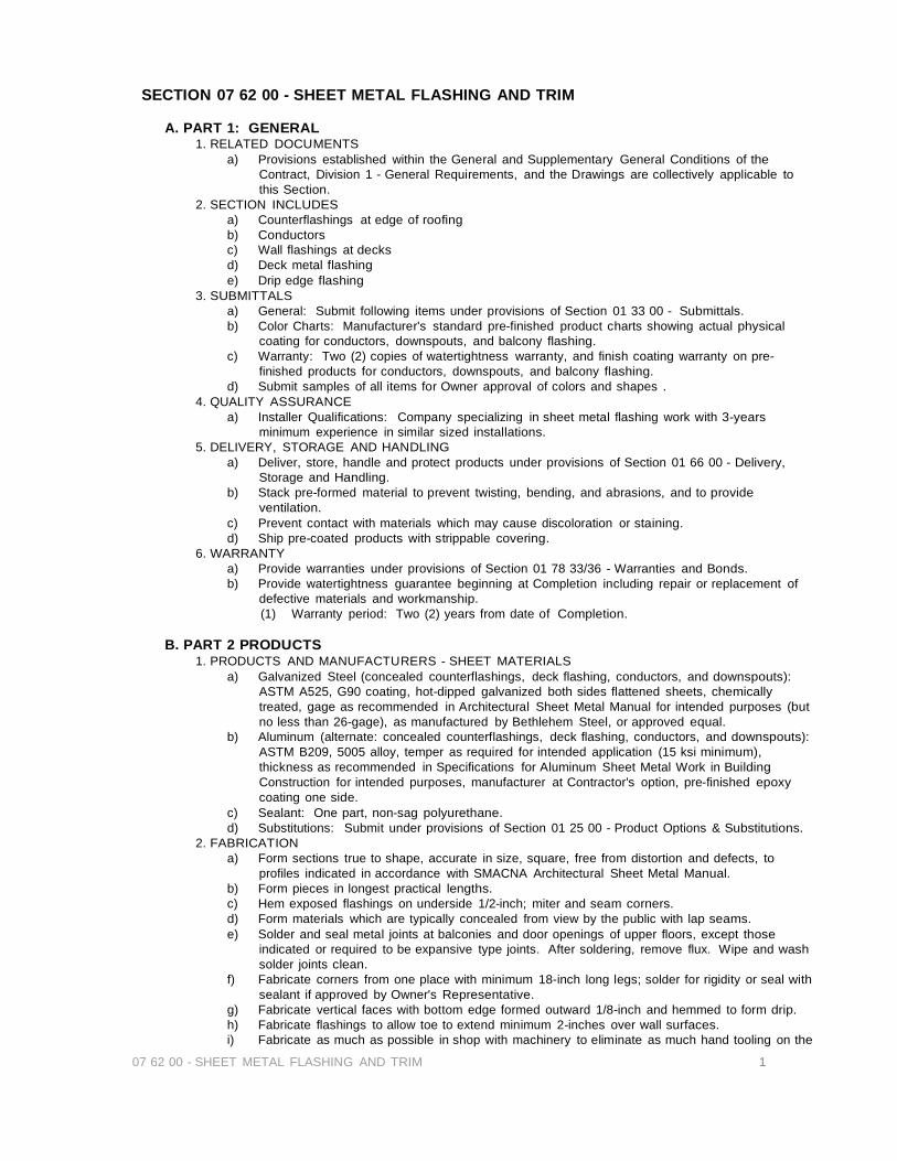
07 62 00 - SHEET METAL FLASHING AND TRIM 1
SECTION 07 62 00 - SHEET METAL FLASHING AND TRIM
A. PART 1: GENERAL 1. RELATED DOCUMENTS
a) Provisions established within the General and Supplementary General Conditions of the Contract, Division 1 - General Requirements, and the Drawings are collectively applicable to this Section.
2. SECTION INCLUDES a) Counterflashings at edge of roofing b) Conductors c) Wall flashings at decks d) Deck metal flashing e) Drip edge flashing
3. SUBMITTALS a) General: Submit following items under provisions of Section 01 33 00 - Submittals. b) Color Charts: Manufacturer's standard pre-finished product charts showing actual physical
coating for conductors, downspouts, and balcony flashing. c) Warranty: Two (2) copies of watertightness warranty, and finish coating warranty on pre-
finished products for conductors, downspouts, and balcony flashing. d) Submit samples of all items for Owner approval of colors and shapes .
4. QUALITY ASSURANCE a) Installer Qualifications: Company specializing in sheet metal flashing work with 3-years
minimum experience in similar sized installations. 5. DELIVERY, STORAGE AND HANDLING
a) Deliver, store, handle and protect products under provisions of Section 01 66 00 - Delivery, Storage and Handling.
b) Stack pre-formed material to prevent twisting, bending, and abrasions, and to provide ventilation.
c) Prevent contact with materials which may cause discoloration or staining. d) Ship pre-coated products with strippable covering.
6. WARRANTY a) Provide warranties under provisions of Section 01 78 33/36 - Warranties and Bonds. b) Provide watertightness guarantee beginning at Completion including repair or replacement of
defective materials and workmanship. (1) Warranty period: Two (2) years from date of Completion.
B. PART 2 PRODUCTS
1. PRODUCTS AND MANUFACTURERS - SHEET MATERIALS a) Galvanized Steel (concealed counterflashings, deck flashing, conductors, and downspouts):
ASTM A525, G90 coating, hot-dipped galvanized both sides flattened sheets, chemically treated, gage as recommended in Architectural Sheet Metal Manual for intended purposes (but no less than 26-gage), as manufactured by Bethlehem Steel, or approved equal.
b) Aluminum (alternate: concealed counterflashings, deck flashing, conductors, and downspouts): ASTM B209, 5005 alloy, temper as required for intended application (15 ksi minimum), thickness as recommended in Specifications for Aluminum Sheet Metal Work in Building Construction for intended purposes, manufacturer at Contractor's option, pre-finished epoxy coating one side.
c) Sealant: One part, non-sag polyurethane. d) Substitutions: Submit under provisions of Section 01 25 00 - Product Options & Substitutions.
2. FABRICATION a) Form sections true to shape, accurate in size, square, free from distortion and defects, to
profiles indicated in accordance with SMACNA Architectural Sheet Metal Manual. b) Form pieces in longest practical lengths. c) Hem exposed flashings on underside 1/2-inch; miter and seam corners. d) Form materials which are typically concealed from view by the public with lap seams. e) Solder and seal metal joints at balconies and door openings of upper floors, except those
indicated or required to be expansive type joints. After soldering, remove flux. Wipe and wash solder joints clean.
f) Fabricate corners from one place with minimum 18-inch long legs; solder for rigidity or seal with sealant if approved by Owner's Representative.
g) Fabricate vertical faces with bottom edge formed outward 1/8-inch and hemmed to form drip. h) Fabricate flashings to allow toe to extend minimum 2-inches over wall surfaces. i) Fabricate as much as possible in shop with machinery to eliminate as much hand tooling on the
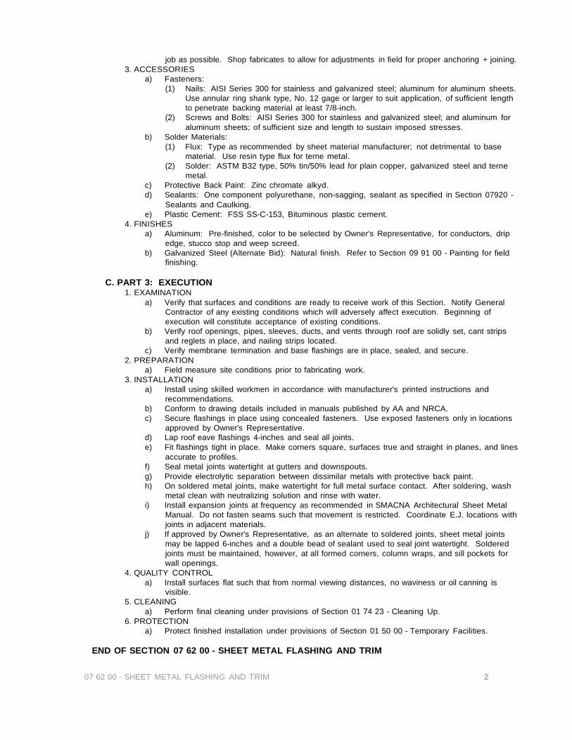
07 62 00 - SHEET METAL FLASHING AND TRIM 2
job as possible. Shop fabricates to allow for adjustments in field for proper anchoring + joining. 3. ACCESSORIES
a) Fasteners: (1) Nails: AISI Series 300 for stainless and galvanized steel; aluminum for aluminum sheets.
Use annular ring shank type, No. 12 gage or larger to suit application, of sufficient length to penetrate backing material at least 7/8-inch.
(2) Screws and Bolts: AISI Series 300 for stainless and galvanized steel; and aluminum for aluminum sheets; of sufficient size and length to sustain imposed stresses.
b) Solder Materials: (1) Flux: Type as recommended by sheet material manufacturer; not detrimental to base
material. Use resin type flux for terne metal. (2) Solder: ASTM B32 type, 50% tin/50% lead for plain copper, galvanized steel and terne
metal. c) Protective Back Paint: Zinc chromate alkyd. d) Sealants: One component polyurethane, non-sagging, sealant as specified in Section 07920 -
Sealants and Caulking. e) Plastic Cement: FSS SS-C-153, Bituminous plastic cement.
4. FINISHES a) Aluminum: Pre-finished, color to be selected by Owner's Representative, for conductors, drip
edge, stucco stop and weep screed. b) Galvanized Steel (Alternate Bid): Natural finish. Refer to Section 09 91 00 - Painting for field
finishing.
C. PART 3: EXECUTION 1. EXAMINATION
a) Verify that surfaces and conditions are ready to receive work of this Section. Notify General Contractor of any existing conditions which will adversely affect execution. Beginning of execution will constitute acceptance of existing conditions.
b) Verify roof openings, pipes, sleeves, ducts, and vents through roof are solidly set, cant strips and reglets in place, and nailing strips located.
c) Verify membrane termination and base flashings are in place, sealed, and secure. 2. PREPARATION
a) Field measure site conditions prior to fabricating work. 3. INSTALLATION
a) Install using skilled workmen in accordance with manufacturer's printed instructions and recommendations.
b) Conform to drawing details included in manuals published by AA and NRCA. c) Secure flashings in place using concealed fasteners. Use exposed fasteners only in locations
approved by Owner's Representative. d) Lap roof eave flashings 4-inches and seal all joints. e) Fit flashings tight in place. Make corners square, surfaces true and straight in planes, and lines
accurate to profiles. f) Seal metal joints watertight at gutters and downspouts. g) Provide electrolytic separation between dissimilar metals with protective back paint. h) On soldered metal joints, make watertight for full metal surface contact. After soldering, wash
metal clean with neutralizing solution and rinse with water. i) Install expansion joints at frequency as recommended in SMACNA Architectural Sheet Metal
Manual. Do not fasten seams such that movement is restricted. Coordinate E.J. locations with joints in adjacent materials.
j) If approved by Owner's Representative, as an alternate to soldered joints, sheet metal joints may be lapped 6-inches and a double bead of sealant used to seal joint watertight. Soldered joints must be maintained, however, at all formed corners, column wraps, and sill pockets for wall openings.
4. QUALITY CONTROL a) Install surfaces flat such that from normal viewing distances, no waviness or oil canning is
visible. 5. CLEANING
a) Perform final cleaning under provisions of Section 01 74 23 - Cleaning Up. 6. PROTECTION
a) Protect finished installation under provisions of Section 01 50 00 - Temporary Facilities.
END OF SECTION 07 62 00 - SHEET METAL FLASHING AND TRIM

07 70 00 MANUFACTURED ROOF SPECIALTIES
SECTION 07 70 00 - MANUFACTURED ROOF SPECIALTIES I.
PART 1 - GENERAL
1.2 SECTION INCLUDES a) Roof vents
1.3 SUBMITTALS
A. Submit the following in accordance with 01 33 00 Submittal Procedures: 1. Shop Drawings: Indicate configuration and dimension of components, adjacent construction,
required clearances and tolerances, and other affected work. 2. Catalog Data: Submit data on shape of components, materials and finishes, anchor types and locations. 3. Samples:
o Submit 2 samples, 12 inch in size illustrating component shape, finish, and color. 4. Installation Instructions: Submit manufacturer’s instructions for special procedures and
perimeter conditions requiring attention.
B. DELIVERY, STORAGE AND HANDLING a) Delivery equipment in manufacturer's protective packaging. b) Store equipment in manufacturer's protective packaging. c) Handle equipment in manner to prevent damage to finished surfaces.
C. PROJECT CONDITIONS a) Protections: Protect pre-finished surfaces from damage or staining. Provide protective covering for
equipment following installation until Date of Completion. D. WARRANTY
a) Furnish [1] year manufacture warranty for roof and specialties finishes as part of Project Closeout Documents.
1.4 QUALITY ASSURANCE A. National Roofing Contractors Association: The NRCA Roofing and Waterproofing Manual. B. Sheet Metal and Air Conditioning Contractors: SMACNA - Architectural Sheet Metal Manual.
PART 2 PRODUCTS
2.1 PRODUCT OPTIONS AND SUBSTITUTIONS A. Comply with Section 01 25 00, Product Options and Substitution. 2.2 MANUFACTURED ROOF SPECIALTIES A. Manufacturers: Air Vent, Inc., 1.800.air.vent 2.3 COMPONENTS
A. Flat Roof Vents: Aluminum 2” x96” continuous screened vents. 1. Need TPO roof vent 2. Need TPO termination bar 3. Need TPO counter-flashing 4.
2.4 ACCESSORIES A. Sealant: Type, as specified in Section 07 92 00. 2.5 FINISHES A. Aluminum: Manufacturer’s standard mill finish. 2.6 EXECUTION 2.7 EXAMINATION
A. Verify deck, curbs, roof membrane, base flashing, and other items affecting Work of this section are in place and positioned correctly.
2.8 INSTALLATION
A. Conform to SMACNA - Architectural Sheet Metal Manual and NRCA - Waterproofing Manual drawing details when there are no specifications, drawings, or details provided in Contract documents.
B. Coordinate installation of components of this section with installation of roofing membrane and base flashings.
C. Coordinate installation of sealants and roofing cement with Work of this section to ensure water tightness.
D. Coordinate installation of flashing flanges into reglets. E. Coordinate installation with roof membrane installation.
II. END OF SECTION 07 70 00 - MANUFACTURED ROOF SPECIALTIES

07 84 00 – FIRESTOPPING 1
SECTION 07 84 00 - FIRESTOPPING
A. PART 1 GENERAL 1. RELATED DOCUMENTS
a) Provisions established within the General and Supplementary General Conditions of the Contract, Division 1 - General Requirements, and the Drawings are collectively applicable to this Section.
2. SECTION INCLUDES a) Installation of firestopping materials at openings and voids in, and at periphery of fire-rated
construction. 3. DEFINITIONS
a) Firestopping: A material, or combination of materials, to retain the integrity of time-rated construction by maintaining an effective barrier against the spread of flame, smoke, and gasses used in specific locations as follows: (1) Ducts, cables, conduits, and piping penetrations through fire-rated floor construction and through
fire-rated partitions. (2) Openings between and at edges of floor slabs (i.e., expansion joints). (3) Penetrations of vertical service shafts. (4) Other locations where specifically shown on the drawings or where required by local codes.
4. QUALITY ASSURANCE a) Materials shall meet and be acceptable for applicable building code. b) Materials shall meet the requirements of NFPA 101 - LIFE Safety Code and NFPA 70 - National
Electrical Code. 5. SUBMITTALS
a) Submit shop drawings, product data, samples, certificates, and manufacturer's installation instructions under provisions of Section 01 33 00 - Submittals.
b) Submit manufacturer's product data for all materials and prefabricated devices, providing descriptions sufficient for identification at the job site. Include manufacturer's instructions for installation.
c) Submit actual samples of each product proposed for use, in its installed state. d) Submit manufacturer's letter of certification, or certified laboratory test report that the material or
combination of materials meet the requirements specified in ASTM E814 and UL 1479 and are so classified in UL's Building Materials Directory.
6. DELIVERY, STORAGE, AND HANDLING a) Deliver, store, handle, and protect products under provisions of Section 01 65 00 – Delivery
Requirements and 01 66 00 Product, Storage and Handling Requirements. b) Deliver in original unopened containers or packages bearing manufacturer's name, brand designation,
and product description. c) Store materials under cover and protected from damage. d) Do not use damaged materials.
7. SEQUENCING / SCHEDULING a) Coordinate the work of this Section with work performed under other Sections of the Project Manual.
B. PART 2 PRODUCTS
1. ACCEPTABLE MANUFACTURERS a) To the extent products of the following manufacturers meet or exceed specified requirements, the
following are acceptable. (1) Electrical Products Division / 3M, St. Paul, MN. (2) Dow Corning Corp., Midland, MI. (3) Standard Oil Engineered Materials. (4) Flamestop Company. (5) Hilti.
b) Other manufacturers: Submit other substitution requests in accordance with requirements of Section 01630 - Product Options & Substitutions.
2. FIRESTOPPING MATERIALS a) Firestopping materials / construction shall constitute one or more of the following products (products of
3M listed as a standard of quality or per governing codes). (1) 3M Brand Caulk CP-25. (2) 3M Brand Putty 303. (3) 3M Brand Wrap / Strip FS-195. (4) 3M Brand Composite Sheet CS-195. (5) 3M Brand Penetrating Sealing Systems 7900 Series. (6) Primer and Damming products compatible with the above materials as certified by firestopping
manufacturer.

07 84 00 – FIRESTOPPING 2
b) Firestopping material shall be asbestos-free and capable of maintaining an effective barrier against flame, smoke and gasses in compliance with the requirements of ASTM E814, and UL 1479
c) Materials shall be suitable for the firestopping of penetrations made by steel, glass, plastic and insulated pipe.
d) On insulated pipe, the fire-rating classification must not require removal of the insulation. e) The rating of the firestops shall be not less than the rating of the time-rated floor or wall assembly.
C. PART 3 EXECUTION
1. PREPARATION a) Clean surfaces to be in contact with firestopping materials of dirt, grease, oil, loose materials, rust, or
other substances that may affect proper fitting or the required fire resistance. 2. INSTALLATION
a) Install firestopping materials as indicated, in accordance with manufacturer's instructions. b) Prime surfaces as recommended by manufacturer. c) Seal all holes or voids made by penetrations to ensure an effective smoke barrier. d) Unless protected from possible loading, install firestopping materials in floors having void openings of
4-inches or more to support the same floor load requirements. e) Tool material after application but before skin forms, to a smooth surface. f) Protect seals from disturbance for 48-hours.
3. FIELD QUALITY CONTROL a) Examine firestopped areas to ensure proper installation prior to concealing or enclosing firestopped
areas. b) Areas of work shall remain accessible until inspection and approval by the applicable code authorities.
END OF SECTION 07 84 00 - FIRESTOPPING

07 92 13 – ELASTOMERIC JOINT SEALANTS (CAULKING) 1
SECTION 07 92 13 – ELASTOMERIC JOINT SEALANTS (CAULKING) A. PART 1 GENERAL
1. REFERENCES a) Standards of the Following as Referenced:
(1) American Society for Testing and Materials (ASTM) (2) Federal Specifications (Fed. Spec.) (3) Sealant and Waterproofer's Institute (SWI)
b) Industry Standards: (1) SWI: Association quality standard guidelines for sealant installation.
2. DEFINITIONS a) Terms:
(1) Caulk: Process of filling joints, without regard to type of material. (2) Caulking compound: Material used in filling joints and seams, having properties of adhesion and
cohesion: not be required to have extensibility and recovery properties, usually applied to joints at interior of structures.
(3) Joint failure: Caulked joint exhibiting one or more of the following characteristics: (a) Leaks air or water. (b) Sealant:
(i) migrates (ii) loses adhesion or cohesion (iii) does not cure (iv) discolors (v) stains adjacent Work (vi) develops bubbles, air pockets, or voids
(4) Sealant: Weatherproof elastomer used in filling and sealing joints, having properties of adhesion, cohesion, extensibility under tension, compressibility, and recovery: designed to make joints air and watertight. Material is designed generally for application to joints at exterior of structures and for other joints subject to movement.
3. SUBMITTALS a) Product data: Submit manufacturer's product description indicating conformance with specified
requirements and installation instructions for each type sealant. Indicate preparation requirements for each substrate condition.
b) Color Samples: (1) Submit samples of manufacturer's standard caulking material colors and special colors indicated
at least 30 days prior to application. (2) Samples: Actual materials or literature depicting actual material colors. Owner's Representive
reserves right to reject Work not in accord with selected colors, based upon samples submitted. (3) Should Owner's Representative select manufacturer meeting specified requirements, except for
minimum color range requirements, he shall be responsible for furnishing special colors within color range requirements. Submit special colors for Owner's Representative acceptance.
4. PROJECT CONDITIONS a) Weather Conditions:
(1) Installation of materials under adverse weather conditions is prohibited: install only within manufacturer recommended temperature range.
(2) Proceed with Work only when forecasted weather conditions are favorable for joint cure and development of high early bond strength.
(3) Install materials only when temperatures are in lower third of manufacturer's recommended installation temperature, wherever joint width is affected by ambient temperature variations.
5. WARRANTY a) Warranty Work to be free from defects in materials and workmanship, including joint failure, for one
year period: begin at Date of Completion.
B. PART 2 PRODUCTS 1. MATERIALS
a) Polyurethane (Type 1 Sealant): (1) One-part conforming to FS TT-S-00227E, Class A, Type I (self-leveling) and ASTM-9200. (2) Color: As selected by Owner. (3) Acceptable products:
(a) Urexpan NR-201, Pecora. (b) Sonolastic SL-1, Sonneborn. (c) Vulkem 45, Mameco.
b) Silicone, General Purpose (Type 2 Sealant): (1) One-part rubber based silicone conforming to FS TT-S-001543, Class A, Type II and ASTM C-
920.

07 92 13 – ELASTOMERIC JOINT SEALANTS (CAULKING) 2
(2) Color: Match substrate. (3) Acceptable products:
(a) 790 Building Sealant, Dow Corning. (b) Silpurf, General Electric.
c) Silicone, Paintable (Type 3 Sealant): (1) One-part silicone rubber sealant for interior use. (2) Acceptable product: Silicone Rubber Sealant, Paintable Dow Corning.
d) Silicone, Sanitary (Type 4 Sealant): (1) One-part conformaing to FS TT-S-001543, F.D.A. Regulation 21 CFR177.2600, and FDA Food Additive Regulation 121.2514. (2) Color: White. (3) Acceptable Products.
(a) (1) 786 Silicone Rubber Sealant, Dow Corning. (b) SCS1702, General Electric.
e) Acrylic Latex (Type 5 Sealant): (1) One-part, non-sag, acrylic latex, meeting requirements of ASTM C834. (2) Acceptable products:
(a) AC-20, Pecora. (b) Sonolac, Sonneborn-Contech, Inc.
f) Acrylic Sealant (Type 6 Sealant): (1) One-part, non-sag, acrylic polymeric conforming to FS TT-S-00230. (2) Acceptable products:
(a)Unicrylic 60, Pecora. g) Polyurethane (Type 7 Sealant):
(1) One-part conforming to FS TT-S-00227E, Class A, Type II (non-sag) and ASTM.920. (2) Color: As selected by Owner. (3) Acceptable products:
(a)Dynatrol I, Pecora. (b)Sonolastic NP-1, Sonneborn. (c)Vulkem 921, Mameco.
h) Foamed-in-place (Type 8 Sealant): (1) Polycell.
2 .ACCESSORIES a) Joint Cleaner: Type recommended by sealant manufacturer for substrates indicated. b) Joint Primer/Sealer: Type recommended by sealant manufacturer for conditions encountered. c) Bond Breaker Tape: Plastic tape applied to contact surfaces where bond to substrate or joint filler
must be avoided for sealant material performance. d) Sealant Backer Rod: (if required)
(1) Type: Compressible rod stock polyethylene foam, polyethylene jacketed polyurethane foam, butyl rubber foam, or neoprene foam: open or closed cell: type recommended by sealant manufacturer for compatibility with material.
(2) Provide size and shape of rod to control joint depth, break bond at joint bottom, form optimum shape of bead on back side, and minimize possibility of extrusion when joint is compressed.
e) Tooling Agent: Agent recommended by sealant or caulk manufacturer to ensure contact of material with inner joint faces.
f) Divider Strips: Synthetic rubber or closed cell synthetic foam not less then 1/16" thick and full depth of caulking material: approved by manufacturers of dissimilar materials as being compatible with each other.
C. PART 3 EXECUTION
1. PREPARATION a) Protection of Adjacent Surfaces:
(1) Protect by applying masking material or manipulating application equipment to keep materials in joint. Allowing tape to touch cleaned surfaces to receive sealant if masking materials are used is prohibited.
(2) Remove misapplied caulking materials from surfaces using solvents and methods recommended by manufacturer.
(3) Restore surfaces to original condition and appearance where caulking materials have been removed.
b) Surface Protection: (1) Clean joint surfaces immediately before caulking joints. Remove dirt, insecure coatings,
moisture, and other substances interfering with bond. (2) Etch concrete and masonry joint surfaces to remove alkalinity, unless caulking material
manufacturer's product data indicates alkalinity does not interfere with bond and performance.
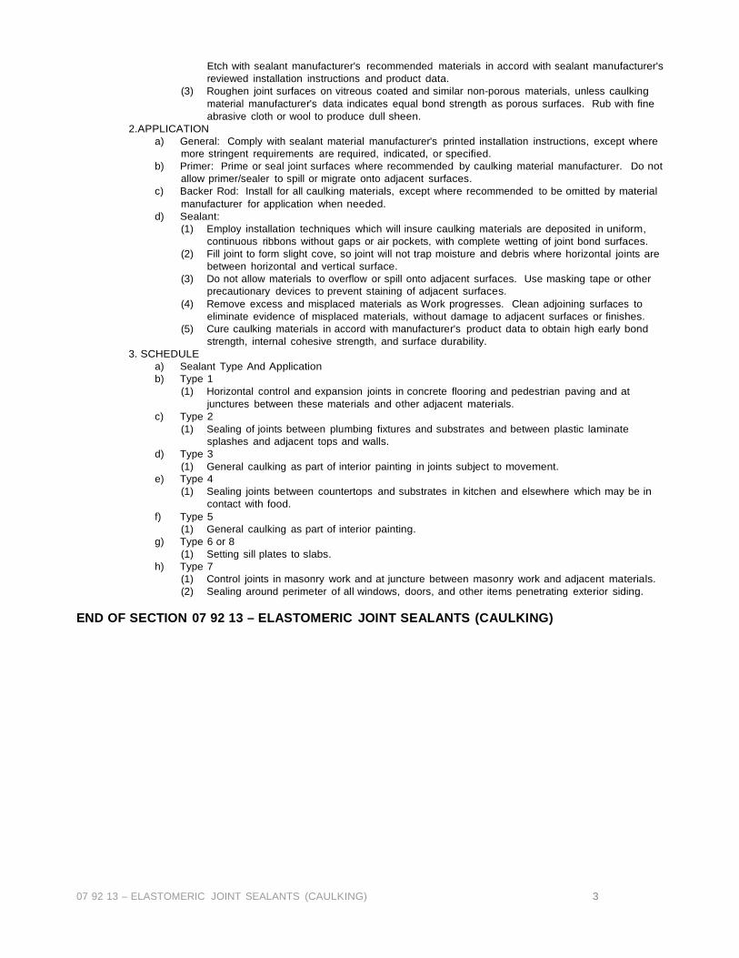
07 92 13 – ELASTOMERIC JOINT SEALANTS (CAULKING) 3
Etch with sealant manufacturer's recommended materials in accord with sealant manufacturer's reviewed installation instructions and product data.
(3) Roughen joint surfaces on vitreous coated and similar non-porous materials, unless caulking material manufacturer's data indicates equal bond strength as porous surfaces. Rub with fine abrasive cloth or wool to produce dull sheen.
2.APPLICATION a) General: Comply with sealant material manufacturer's printed installation instructions, except where
more stringent requirements are required, indicated, or specified. b) Primer: Prime or seal joint surfaces where recommended by caulking material manufacturer. Do not
allow primer/sealer to spill or migrate onto adjacent surfaces. c) Backer Rod: Install for all caulking materials, except where recommended to be omitted by material
manufacturer for application when needed. d) Sealant:
(1) Employ installation techniques which will insure caulking materials are deposited in uniform, continuous ribbons without gaps or air pockets, with complete wetting of joint bond surfaces.
(2) Fill joint to form slight cove, so joint will not trap moisture and debris where horizontal joints are between horizontal and vertical surface.
(3) Do not allow materials to overflow or spill onto adjacent surfaces. Use masking tape or other precautionary devices to prevent staining of adjacent surfaces.
(4) Remove excess and misplaced materials as Work progresses. Clean adjoining surfaces to eliminate evidence of misplaced materials, without damage to adjacent surfaces or finishes.
(5) Cure caulking materials in accord with manufacturer's product data to obtain high early bond strength, internal cohesive strength, and surface durability.
3. SCHEDULE a) Sealant Type And Application b) Type 1
(1) Horizontal control and expansion joints in concrete flooring and pedestrian paving and at junctures between these materials and other adjacent materials.
c) Type 2 (1) Sealing of joints between plumbing fixtures and substrates and between plastic laminate
splashes and adjacent tops and walls. d) Type 3
(1) General caulking as part of interior painting in joints subject to movement. e) Type 4
(1) Sealing joints between countertops and substrates in kitchen and elsewhere which may be in contact with food.
f) Type 5 (1) General caulking as part of interior painting.
g) Type 6 or 8 (1) Setting sill plates to slabs.
h) Type 7 (1) Control joints in masonry work and at juncture between masonry work and adjacent materials. (2) Sealing around perimeter of all windows, doors, and other items penetrating exterior siding.
END OF SECTION 07 92 13 – ELASTOMERIC JOINT SEALANTS (CAULKING)
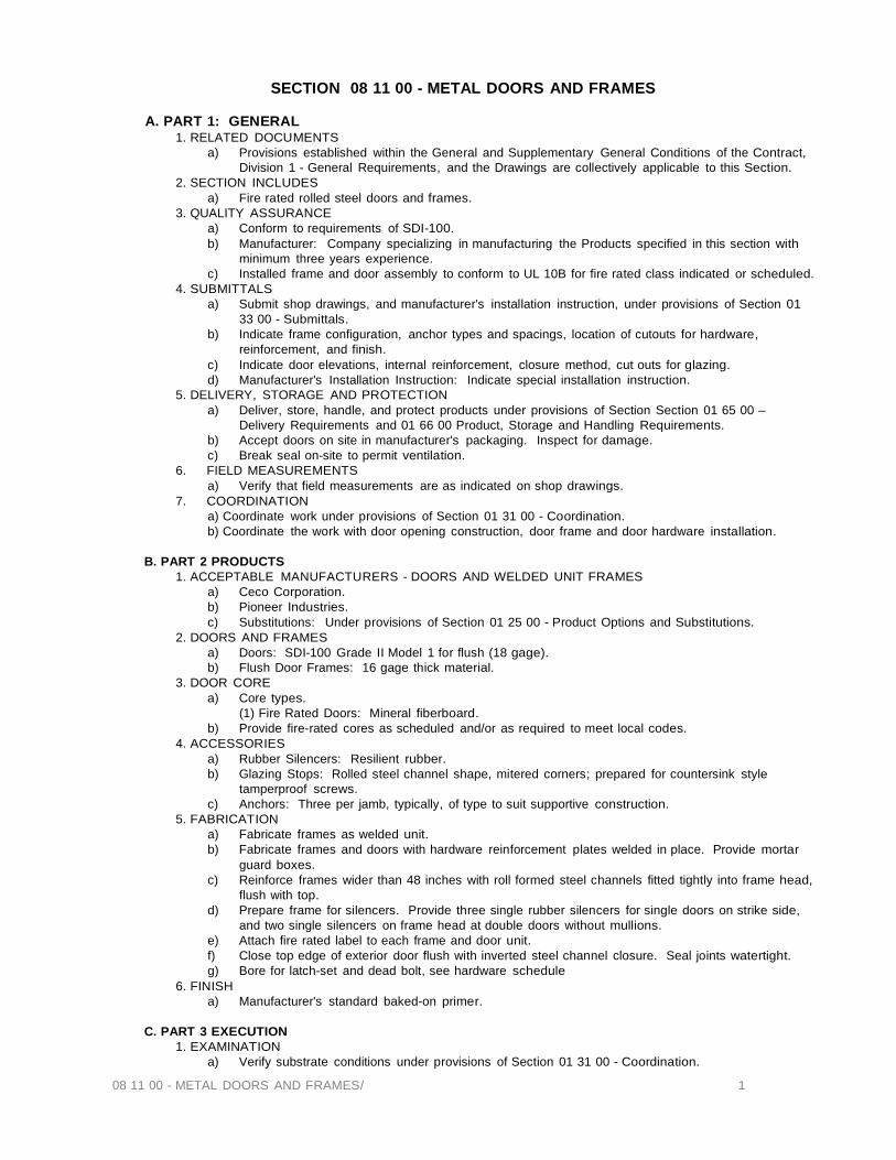
08 11 00 - METAL DOORS AND FRAMES/ 1
SECTION 08 11 00 - METAL DOORS AND FRAMES
A. PART 1: GENERAL 1. RELATED DOCUMENTS
a) Provisions established within the General and Supplementary General Conditions of the Contract, Division 1 - General Requirements, and the Drawings are collectively applicable to this Section.
2. SECTION INCLUDES a) Fire rated rolled steel doors and frames.
3. QUALITY ASSURANCE a) Conform to requirements of SDI-100. b) Manufacturer: Company specializing in manufacturing the Products specified in this section with
minimum three years experience. c) Installed frame and door assembly to conform to UL 10B for fire rated class indicated or scheduled.
4. SUBMITTALS a) Submit shop drawings, and manufacturer's installation instruction, under provisions of Section 01
33 00 - Submittals. b) Indicate frame configuration, anchor types and spacings, location of cutouts for hardware,
reinforcement, and finish. c) Indicate door elevations, internal reinforcement, closure method, cut outs for glazing. d) Manufacturer's Installation Instruction: Indicate special installation instruction.
5. DELIVERY, STORAGE AND PROTECTION a) Deliver, store, handle, and protect products under provisions of Section Section 01 65 00 –
Delivery Requirements and 01 66 00 Product, Storage and Handling Requirements. b) Accept doors on site in manufacturer's packaging. Inspect for damage. c) Break seal on-site to permit ventilation.
6. FIELD MEASUREMENTS a) Verify that field measurements are as indicated on shop drawings.
7. COORDINATION a) Coordinate work under provisions of Section 01 31 00 - Coordination. b) Coordinate the work with door opening construction, door frame and door hardware installation.
B. PART 2 PRODUCTS
1. ACCEPTABLE MANUFACTURERS - DOORS AND WELDED UNIT FRAMES a) Ceco Corporation. b) Pioneer Industries. c) Substitutions: Under provisions of Section 01 25 00 - Product Options and Substitutions.
2. DOORS AND FRAMES a) Doors: SDI-100 Grade II Model 1 for flush (18 gage). b) Flush Door Frames: 16 gage thick material.
3. DOOR CORE a) Core types.
(1) Fire Rated Doors: Mineral fiberboard. b) Provide fire-rated cores as scheduled and/or as required to meet local codes.
4. ACCESSORIES a) Rubber Silencers: Resilient rubber. b) Glazing Stops: Rolled steel channel shape, mitered corners; prepared for countersink style
tamperproof screws. c) Anchors: Three per jamb, typically, of type to suit supportive construction.
5. FABRICATION a) Fabricate frames as welded unit. b) Fabricate frames and doors with hardware reinforcement plates welded in place. Provide mortar
guard boxes. c) Reinforce frames wider than 48 inches with roll formed steel channels fitted tightly into frame head,
flush with top. d) Prepare frame for silencers. Provide three single rubber silencers for single doors on strike side,
and two single silencers on frame head at double doors without mullions. e) Attach fire rated label to each frame and door unit. f) Close top edge of exterior door flush with inverted steel channel closure. Seal joints watertight. g) Bore for latch-set and dead bolt, see hardware schedule
6. FINISH a) Manufacturer's standard baked-on primer.
C. PART 3 EXECUTION
1. EXAMINATION a) Verify substrate conditions under provisions of Section 01 31 00 - Coordination.

08 11 00 - METAL DOORS AND FRAMES/ 2
b) Verify that opening sizes and tolerances are acceptable. c) Verify surfaces and conditions are ready to receive work of this section. Notify Owner's
Representative of any existing conditions which will adversely affect execution. Beginning of execution will constitute acceptance of existing conditions.
2. INSTALLATION a) Install frames in accordance with SDI-105 and reference U.L. publication. b) Install doors in accordance with DHI and reference U.L. publication. c) Coordinate with wallboard construction for anchor placement. d) Coordinate installation of glass and glazing. e) Install roll formed steel reinforcement channels between two abutting frames. Anchor to structure
and floor. f) Set frames plumb, level, and true alignment, securely fastened to the floor and adjoining walls. g) Install doors accurately in frames, maintaining specified clearances.
3. TOLERANCES a) Maximum Diagonal Distortion: 1/8“ measured with straight edge, corner to corner.
4. ADJUSTING AND CLEANING a) Adjust hardware and door movement for smooth, quiet and balanced door movement.
END OF SECTION 08 11 00 - METAL DOORS AND FRAMES

Section 08 11 13 Metal Doors
Section 08 11 13 Metal Doors Therma-Tru® Multi-Family and Light Commercial steel doors and frames PART 1 GENERAL
1.01 SUMMARY A. Section Includes: Steel doors, steel frames, louvers, transoms, side lites and decorative glass and patio doors B. Related sections include:
1. Masonry: Division 4 Masonry sections. 2. Carpentry: Division 6 3. Sealants: Division 7 Joint Sealer Section. 4. Glass and Glazing: Division 8 Glass and Glazing Section 5. Hardware: Division 8 Hardware Section 6. Drywall construction: Division 9 Wall Board Assemblies Section. 7. Painting: Division 9 Painting Sections
1.02 REFERENCES
A. General: Standards listed by reference including revisions by issuing authority, form a part of this specification section to the extent indicated. Standards listed are identified by the issuing authority, authority abbreviation, designation number, title or other designation, title or other designation established by issuing authority. B. American Society for testing and Materials (ASTI\Il):
1. ASTM A366 Standard Specification for Commercial Steel (CS) Sheet, Carbon (0.15 Maximum percent) Cold-Rolled. 2. ASTM A 653 Standard Specification for Steel Sheet Zinc Coated (Galvanized) or Zinc-Iron Alloy-Coated (Galvannealed) by the Hot Dip process. 3. ASTM A924 Standard Specification for General Requirements for steel sheet, metallic Coated by the Hot-Dip process. 4. ASTM D610 Standard Test Method for Evaluating Degree of Rust on Painted Steel Surfaces. 5. ASTM D714 Standard Test Method for Evaluating Degree of Blistering of Paints. 6. ASTM D1622 Standard Test Method for Apparent Density of Rigid Cellular Plastics. 7. ASTM D1654 Standard Test Method for Evaluation of Painted or Coated Specimens Subjected to Corrosive Environments.
C. American National Standards Institute (ANSI): 1. ANSIjDHI A115.IG Installation Guide for Doors and Hardware. 2. ANSIjSDI Standard A224.1 Test Procedure and Test Criteria for Prime Painted Steel Surfaces for Steel Doors and Frames.
D. Window and door Manufacturer's Association (WDMA)
1. N.A.F.S. 101/LS.2/A440 2. AAMA/WDMA 101/1.S.2/-NAFS-02 3. AI'JSI/AAMA 101/1.5.2-97
E. Warnock Hersey, Inc. (WHI):
1. WHI Directory of Listed Products. 2. WHI Directory of Positive Pressure-Rated Door Assemblies and Components 3. SpecDirect web based listing of fire-rated components and systems.
1.03 SYSTEM DECSRIPTION
A. Performance Requirements: provide metal doors and frames which have been manufactured, fabricated and installed
to maintain performance criteria stated by the manufacturer without defects, damage or failure.
1.04 SUBMITTALS
A. General: Submit listed submittals in accordance with Conditions of the Contract and Division 1 Submittals Procedures Section. B. Product Data: Submit Product Data, including manufacturers' product sheet for specified products. C. Shop Drawings: Submit Shop Drawings showing layout, profiles and product components including anchorage and accessories.
1. Indicate door type! frame! steel, core, material thickness, reinforcements! anchorages! exposed fasteners, hardware locations, openings (glazed! paneled or louvered) and hardware arrangement. 2. Include schedule identifying each unit with door marks or numbers referencing schedules and drawings.
D. Samples: Submit selection and verification samples for finishes, colors! and textures. Coordinate with Division 9 Painting Section for paint finishes. E. Quality Assurance Submittals: Submit the following:
1. Certificates: Product certificates signed by the manufacturer certifying that materials comply with specified performance characteristics and criteria and physical requirements. 2. Manufacturer's instructions: Manufacturer's Installation Instructions. 3. Manufacturer's Field Reports: Specified herein.
F. Closeout Submittals: Submit the following: 1. Operation and maintenance data: Operation and maintenance data for installed products in accordance with
Division 1 Closeout Submittals (Maintenance Data and Operation Data) section. Include methods for maintaining installed products and precautions against cleaning materials and methods detrimental to finishes
Section 08 11 13 Metal Doors
and performance. 2. Warranty: Warranty documents specified herein.
1.05 QUALITY ASSURANCE
A. Installer qualifications: Installer should be experienced in performing work of this section and should have specialized in the installation of work similar to that required for this project.
1. Certificate: When requested submit certificate indicating qualifications. B. Regulatory requirements: Specify applicable requirements of regulatory agencies.
1. Labeled Door and frame construction. Where noted or required provide Warnock Hersey labels with appropriate fire and or smoke resistance ratings for the opening as indicated. 2. Provide door and frame assemblies with the construction and assembly configurations as required by the National Accreditation Management Institute pursuant to meeting code and or local requirements for structural and or impact performance.
C. IVlock-ups: Install at project site a job mock-up using acceptable products and manufacturer approved installation methods. Obtain owner's and Architect's acceptance of finish color, texture pattern, and workmanship standards. Comply with Division 1 Quality Control (Mock-ups requirements) Section.
1. Mock-up size: Specify size of mock-up. 2. Maintenance: maintain mock-up during construction for workmanship comparison; remove and legally dispose of mock-up if it is no longer required. 3. Incorporation: Mock up shall be incorporated into final construction upon Owner or Architect's approval.
D. Pre-installation Meetings: Conduct preinstallation meeting to verify project requirements, substrate conditions, manufacturer's installation instructions, and manufacturer's warranty requirements.
1.06 DELIVERY, STORAGE and HANDLING A. General: comply with manufacturer's ordering instructions and lead-time requirements to avoid construction delays. B. Delivery: Deliver materials in manufacturer's original, unopened, undamaged containers with identification labels intact.
1. Handle and store products according to Therma-Tru recommendations published in technical materials. Leave product wrapped or otherwise protected and under clean dry storage conditions until required.
C. Storage and Protection: Store materials protected from exposure to harmful weather conditions, at temperature and humidity conditions recommended by the manufacturer.
1. Pre-Hung Door/frame assemblies: Pre-hung Units shall be stored in an upright position under cover on building site on wood sills or floor in a manner that will prevent rust and damage. Remove plastic wrap packaging as required from packaged Pre-hungs as necessitated by high humidity conditions. Avoid creating a humidity chamber by using a plastic or canvas shelter and not venting the area covered. 2. Door Storage: Units shall be stored in an upright position under cover on building site on wood sills or floor in a manner that will prevent rust and damage. Remove plastic wrap packaging as required from packaged doors as necessitated by high humidity conditions. Avoid creating a humidity chamber by using a plastic or canvas shelter and not venting the area covered. Doors shall be protected at corners to prevent damage or marring to finish. 3. Frame Storage: Frame Units shall be stored under cover on building site on wood sills or floor in a manner that will prevent rust and damage. Remove plastic wrap packaging as required from packaged Pre-hungs as necessitated by high humidity conditions. Avoid creating a humidity chamber by using a plastic or canvas shelter and not venting the area covered.
1.07 PROJECT CONDITIONS
A. Field measurements: Verify actual measurements/openings by field measurements before fabrication: show recorded measurements on shop drawings. Coordinate field measurements and fabrication schedule with construction progress to avoid construction delays.
1.08 WARRANTY A. Project Warranty: Refer to conditions of the contract for project warranty provisions. B. Manufacturer's warranty: Submit for owner's acceptance, manufacture's standard warranty documented by an authorized company official. 1. Manufacturer's warranty commencing on shipment date.
PART 2 PRODUCTS
2.01 STEEL DOORS AND FRAMES A. Manufacturer: Therma-Tru Doors (OR other manufacturer accepted by Architect)
1. Contact: 1750 Indian Wood Circle, Maumee, OH 43537; Telephone: (419) 891-7400; Fax: (419) 482-9100; Web: www.thermatru.com
B. Proprietary Products and Systems: Therma-Tru Metal Doors and frames.
1. Flush Models in 24 Therma-Tru. 2. Lighted Models in 24 Therma-Tru 3. Embossed Models in 24 Therma-Tru 4. Adjusta-Fit®-Commercial grade 16 gauge steel wall adjustable frame engineered for optimum fit and performance for masonry and stud construction. Ideal for unit entries from outside or corridor.
C. Sizes: 1. Standard door sizes; as indicated on drawings.
Section 08 11 13 Metal Doors
D. Fire rating: Provide doors and frames with Warnock Hersey (Intertek Services) where specified. E. Sound rating: Provide sound transmission class of standard units tested as required F. Finishes:
1. Exposed surfaces on doors and frames shall be cleaned and painted with a rust inhibiting primer. Prime painted system shall be tested at a recognized independent laboratory in accordance with ANSI/SDI standard A.250.10 and meet the acceptance criteria as outlined in that document and required by the architect or owner. 2. Colors: Finish doors with primer paint ready for field painting.
2.02 PRODUCT SUBSTITUTIONS
A. Substitutions allowed if they meet or exceed these specifications.
2.03 MATERIALS A. Steel materials:
1. Cold rolled steel: comply with ASTM A366 cold rolled carbon sheet steel. 2. Galvanized steel: comply with ASTM A924 general requirements for steel metallic coated by hot dip process.
B. Primer materials: Comply with ANSI A2S0.10 test procedures and acceptance criteria for prime painted steel surfaces for steel doors and frames.
2.04 DOORS A. Therma-Tru Light Commercial and Multi-Family Doors; Therma-Tru standard, ProEdge adjustable hinge and 12-24 TR Series steel doors
1. Fire-Rating-All Doors available with up to 90 minute Positive Pressure Fire-Rating from Warnock Hersey. 2. Doors shall have four inch high hinge preps machined, reinforced as follows:
a. Therma-Tru standard-18 gauge plates reinforcements to receive 12-24 screws for secure anchoring
of hinges b. ProEdge™ adjustable hinge-16 gage plates counter-sunk and extruded and tapped to 10 gauge
equivalent to receive 12-24 screws for secure anchoring of hinges c. 12-24 TR Series-l0 gage plates tapped to receive 10-24 screws for secure anchoring of hinges
3. Styles & Sizes-Door is available flush or embossed, in 6'8" & 7'0" heights. High definition styles available for
Therma-Tru pre-hungs. 4. Steel face sheets shall be 24 Therma-Tru galvanized tension leveled steel for superior flatness & enhanced
corrosion resistance. 5. Paint Finish-Doors shall receive a factory prime finish for added rust inhibition. Primed surface shall be suitable
for maximum adhesion of finish top coat. 6. Insulated-Doors shall be foamed in place, stiffened & structurally reinforced with environmentally friendly
polyurethane and bonded to inside skins with minimal voids. 7. Rugged Construction-The door edges shall be mechanically overlapped and reinforced the full height on both
sides of door and adhered with foamed in place polyurethane. The door shall be stiffened with integrally formed top and bottom rails securely welded at top and bottom of door with two welds each.
8. Advanced Lock Reinforcing -Latching and deadlocking hardware is supported with an advanced injection molded composite lock reinforcement with superior screw holding power. Advanced door avoids the problem of 'telegraphing' of the lock reinforcement typical with wood blocks. Design also allows for uniform foam flow for a flatter door face at lock area.
9. Lock Machining-Lock preparations include 2-1/8" face bores at both 2-3/4" & 2-3/8" backsets. Edge preps for cylindrical preps shall feature 2-1/4" x 1-1/8". Deadlock edge prep located at 51/2" centers to latching edge prep. Deadlock cross bore optional.
10. Mortise lock preps available for card reader and other commercial applications. 11. Surface Mounted Hardware-Exit hardware and closure reinforcements shall be fabricated from 16 gage steel x
5" x 20" securely attached to both skins of the door. 12. Screw applied bottom sweep for enhanced water and air infiltration resistance. Slide on double bulb sweep
option for ProEdge doors with screwless application.
2.05 MANUFACTURED FRAME UNITS A. Therma-Tru-Tru Light Commercial and Multi-Family Steel Fames-AdjustaFit. Our Adjusta -Fit® split-steel frame technology ensures optimum fit and performance. Ideal for interior as well as exterior applications, for suite entries from the outside or corridor.
1. Acceptable product: Therma-Tru Adjust-Fit Steel Frame. 2. Construction: Two-piece frames constructed of galvanized steel conforming to ASTM A 653, commercial
quality, with A 40 coating 3. Designed for use in remodellng and new construction applications. 4. 90-minute positive pressure fire-rated with available 20-minute smoke rating from ITS/Warnock Hersey. 5. Base frame component: 16 gauge. The heaviest gauge available for split adjustable pre-hung steel frames. 6. Closure frame component: 22 gauge. 7. Profiles: Interlocking base and closure profiles for V2 inch throat dimension adjustment; manufacturer's
standard throat dimensions to accommodate wall thicknesses 3-3/8 inches to 10 inches. 8. Single rabbet; rabbet for 1-3/4 inch door thickness on stop side of frame, 5/8 inch high stop with kerf for
weatherstrip, 1-13/16 inches wide trim face, no return legs. 9. Corners: Butted at intersections of head and jambs. 10. Hardware preparation: Frames prepared for hardware, reinforced as follows:
a. Hinges: Stamped integral pocket provided for full-4inches by 4-hinges. located in accordance with manufacturers specifications
Section 08 11 13 Metal Doors
b. Strike: Reinforcement integral with frame, commercial strike option of 4-7/8" 115.1 ANSI prep. c. Strike adapter plate for 'T' strike or full lip strike, both with or without deadbolt d. Surface-mounted hardware: Reinforcement of minimum 16 gauge provided for other door hardware.
11. Weatherstrip: Manufacturer's standard foam filled compression weatherstrip, installed in kerf of frame. 12. Threshold: Manufacturer's standard two-piece type of extruded aluminum, mill finish with safety ribs, 4 inches
wide by '/2 inch height; ribbed extruded vinyl sweep across door bottom. 13. Frame finish: Field-applied. 14. Wood casings: Specified in Section 06200
C. Therma-Tru Light Commercial and Multi-Family Steel Fames-Secura-Fit.
1. Acceptable product: Therma-Tru Secura-Fit Steel Frame 2. Construction: 16 gauge galvanized steel conforming to ASTM A 653, commercial quality, A40 coating, and as follows: 3. Profile: L-shape profile for 1-3/4 inch door thickness, flat face punched with elongated fastener holes, primed wood stops kerfed for weather-strip. 4. Corners: Butted at intersections of head and jambs. 5. Hardware preparation: Frames prepared for hardware, reinforced as follows:
a. Hinges reinforced for 4-inches by 4-inches located in accordance with manufacturers specifications. b. Strike: Reinforcement for 2-3/4 tee strike, integral with frame, located in accordance with manufacturers specifications c. Surface-mounted hardware: Concealed reinforcement of minimum 16 gauge. d. Therma-Tru provided for other door hardware as specified in Section 08710.
6. Weatherstrip Manufacturer's standard foam filled compression weatherstrip, installed in kerf of applied stop. 7. Threshold: Manufacturer's standard two-piece type of extruded aluminum, mill finish with safety ribs, with interlocking extruded sill component, adjustable for wall thickness variation; ribbed extruded vinyl sweep across door bottom. 8. Frame finish: Field Finish.
11. Wood casings: Specified in Section 06200
2.06 RELATED MATERIALS
A. Related materials: Refer to other sections
2.07 SOURCE QUALITY A. Source quality: Obtain metal door and frame products from manufacturers Inspected and audited by third party inspection agencies such as Intertek Services and the National Accreditation Management Institute.
PART 3 EXECUTION
3.01 MANUFACTURER'S INSTRUCTIONS A. Compliance: Comply with manufacturer's product data, including product technical bulletins, product catalog installation instructions and product carton instructions for installation.
3.02 EXAMINATION A. Site Verification of Conditions: Verify that substrate conditions, which have been previously installed under other sections, are acceptable for product installation in accordance with manufacturer's instructions.
1. Verify that door frame openings are installed plumb, true and level before beginning installation process. Select fasteners of adequate type, number and quality to perform the intended functions.
3.03 PREPARATION
A. Surface Preparation: 1. Preparation for Field Painting: Before application of finish coat of paint, surfaces must be dry and free of dirt, oil and dust. Finish coat shall be applied over a film which is intact. Scratches or bare edges shall be field primed with a rust inhibiting paint before top coating. Comply with instructions on finish coat application provided by paint manufacturer.
3.04 INSTALLATION A. General:
1. Set frame product plumb, square, aligned and without twist at correct elevation. 2. Frame Installation: Install steel frames. Installation shall be plumb, straight and true, rigidly secured in place, and properly braced. Comply with Manufacturer's installation instuctions and AI\lSI/DHI AllS-IG installation guide.
B. Installation: 1. L Secure anchorages and connections to adjacent construction. 2. 2, Install hardware in accordance with manufacturers' templates and instructions. 3. Finish exposed field welds to present a smooth uniform surface. Touch up with a rust inhibitive primer. 4. Touch up exposed surfaces scratched or marred during shipment, installation or handling with a rust inhibitive
primer. 5. Install glazing materials and compression weatherstrip.
C. Installation Reference Standard(s): Install metal doors and frames in accordance with requirements of applicable reference standards. 1. Comply with Door and Hardware Institute (DHI) installation standards. 2. Comply with Steel Door Institute (SOl) installation and maintenance standards.

Section 08 11 13 Metal Doors
3. Comply with NFPA80 installation standards.
E. Related Products Installation: Refer to other sections listed under Related Sections for related products installation.
3.06 ADJUSTING A. Adjusting: Adjust hinge sets, locksets and other hardware. Lubricate using a suitable lubricant compatible with door and
frame coatings.
3.07 CLEANING A. Cleaning: Remove temporary coverings and protection of adjacent work areas. Repair or replace products that have been
installed and are damaged. Clean installed products in accordance with manufactu rer's instructions prior to Owner's acceptance. Remove construction debris from project site and legally dispose of debris.
3.08 PROTECTION
A. Protection: Protect installed product and finish surfaces from damage during construction.
3.09 SCHEDULES A. See door schedules on drawings.
END OF SECTION

Section 08 14 23.19 Molded Hardboard Faced Wood Doors
Section 08 14 23.19 Molded Hardboard Faced Wood Doors (MASONITE Molded Panel Series Composite Particleboard Core Interior Doors)
Part 1: GENERAL 1.1 Scope: Subject to local building codes, this product is intended for use in: 1.1.1 Single family dwelling interior applications. 1.1.2 Multifamily dwelling, low-rise professional office, library, and low-rise motel interior applications. 1.1.3 Lighter use industrial building and factory, hotel, and retail sales building interior applications. 1.2 Product Description: 1-3/8" side-hinged door systems manufactured by MASONITE. 1.2.1 Door system components include: door panel(s), bifold panel(s), door frame, hinges.
Part 2: BASIC MATERIALS 2.1 Door Panel: Masonite 6 Panel Smooth Colonist Molded Panel doors shall be fabricated using loose lay up assembly that includes molded wood fiber facings, wood stiles, wood or MDF rails and particleboard core. Door facings are to be bonded to stiles, rails, and core forming a 3-ply structural attachment. Water based latex primer used on door facings (stile and rails per request) unless factory pre-finished. 2.1.1 Hinge preparations for 1-3/8" thick doors to be machined to accept 3-1/2" hinges. Face bore(s) for cylindrical lock and dead bolt are to be 2-1/8" diameter at 2-3/4" or 2-3/8" backset. 2.1.2 Vertical edge of door to be square, beveled both sides or lock stile only. Edge preparation should be clearly noted when the product is ordered. 2.2 Door Frame: Wood jambs shall be fabricated as a flat jamb with doorstop applied. Hinge jamb preparations for 1-3/8" thick doors to be machined to accept 3-1/2" hinges. Strike jamb preparations are to be machined for full lip cylindrical strike plate. Double door units shall include preparations for ball catch located at the top of door on both door panels designed to strike into the head jamb. 2.3 Hinges: (3) standard weight radius mortise hinges are required on doors TO" height or smaller & (4) on doors greater than TO".
Part 3: DELIVERY, STORAGE & HANDLING 3.1 Delivery: Reasonable care shall be exercised during shipping and handling in keeping with the decorative nature of product. 3.2 Storage & Protection: Store upright in a dry, well-ventilated building or shelter at a constant temperature. Do not store in damp, freshly plastered, drywall or concrete areas until materials have completely dried. Doors should be stored at least 10' away from any heat source to help prevent uneven drying. Doors must be sealed with an oil-based sealer or primer if stored for long periods.
Part 4: EXECUTION 4.1 Examination: Site verification of substrate conditions, which have been previously completed, are acceptable for the product installation instructions in accordance with manufacturer's specifications. Verify that door frame openings are constructed plumb, true and level before beginning installation process. Select fasteners of adequate type, number, and quality to perform the intended functions. 4.2 Installation: Remove protective packaging just prior to installation. Installer shall be experienced in performing work required and shall be specialized in the installation of work similar to that required for this project. Comply with manufacturer's product data, including product technical bulletins, product catalog installation instructions and product packaging instructions for installation. 4.3 Finishes: See Masonite -How to Paint instructions for complete finishing details. Various types of materials are used in the construction of the door system; each shall be sealed in accordance with manufacturer's specifications to protect against various environmental conditions. Make sure to completely seal and inspect all 6-surfaces (top, hinge side, bottom, lock side, in the construction of the door system; each shall be sealed in accordance with manufacturer's specifications to protect against various environmental conditions. Make sure to completely seal and inspect all 6-surfaces (top, hinge side, bottom, lock side, in front face and back face) with two-coat minimum on operable panel(s). Finishing and/or re-finishing must be completed immediately after door has acclimated to the environment where it is to be installed and within a maximum of 7 days. Avoid finishing after a rain or damp and during periods of higher than average humidity. Conduct periodic inspections of all coated surfaces to insure that door components are not exposed. Inspections should occur at least once a year. Reseal the surface as needed.
Part 5: GENERAL PERFORMANCE 5.1 Acoustical Performance: Unit scheduled for installation in opening requiring a specific noise control rating shall be clearly noted when product is ordered. 1-3/4" thick Molded Panel Series door with particleboard core sound transmission class (STC) rating is 29. (See acoustical performance data for unit specific acoustical information.) 5.2 Thermal Performance: Unit scheduled for installation in opening requiring a specific thermal rating shall be clearly noted when product is ordered. 1-3/4" thick Molded Panel door with particleboard core at R-value of 3.54. (See thermal performance data for unit specific thermal information.) 5.3 Fire Resistance: Unit scheduled for installation in openings requiring compliance with national, state or local fire guidelines shall be clearly noted when product is ordered. Masonite· 1-3/4" Molded Panel Series door panels have been evaluated for use as fire doors in 20-minute locations. Labeling is available under the Intertek Testing services 1 Warnock Hersey program. Fire doors require the use of a fire rated frame system and must be installed in accordance with NFPA 80 guidelines. (Please check with manufacturer or distributor for limitations of use).
Part 6: WARRANTY 6.1 Limited 1-Year -Please check with manufacturer or distributor for current warranty terms and conditions.
END SECTION 08 14 23.19 MOLDED HARDBOARD-FACED WOOD DOORS (MASONITE)

SECTION 08 31 00 - Access Doors and Panels
A. PART 1 - GENERAL 1. RELATED DOCUMENTS
a) Provisions established within the General and Supplementary General Conditions of the Contract, Division 1 - General Requirements, and the Drawings are collectively applicable to this Section.
b) Section 06 10 00 - Rough Carpentry c) Section 09 26 00 - Gypsum Board Systems d) Section 09 90 00 - Painting
2. SECTION INCLUDES a) Access door and frame units for plumbing or miscellaneous access. b) Wall locations.
3. SUBMITTALS a) Submit under provisions of Section 01 33 00 - Submittals. b) Product Data: Provide sizes, types, finishes, scheduled locations, and details of adjoining work. c) Submit manufacturer's installation instructions under provisions of Section 01340 - Submittals.
4. REGULATORY REQUIREMENTS a) Conform to applicable code for fire rated access units.
5. COORDINATION a) Coordinate work under provisions of Section 01 31 00 - Coordination. b) Coordinate the work with mechanical and electrical work requiring access units.
B. PART 2 - PRODUCTS
1. MANUFACTURERS - WALL UNITS a) Milcor, Inc. b) J.L. Industries. c) KARP, Associates. d) Substitutions: Under provisions of Section 01 25 00 - Product Options and Substitutions. e) Products listed herein are those of Milcor, Inc., as standard of quality.
2. ACCESS UNITS - WALLS a) Non-Fire Rated Door and Frame Unit: Formed steel
(1) In Gypsum Board on Wood Studs: Model DW 3203 manufactured by Milcor. b) 1 hour fire rated door and frame unit, formed steel. c) Fire rated door and frame unit, lockable.
4. FABRICATION - WALL UNITS a) Fabricate frames and flanges of 22 gage steel. b) Fabricate door panels of 22 gage steel single thickness steel sheet. c) Weld, fill, and grind joints to assure flush and square unit. d) Hardware
(1) Hinge: 175 degree steel hinges with removable pin. (2) Lock: Screw driver slot for quarter turn cam lock.
5. FINISHES a) Base Metal Protection: Prime coat units with baked on primer.
C. PART 3 - EXECUTION
1. EXAMINATION a) Verify substrate conditions under provisions of Section 01 31 00 - Coordination. b) Verify that rough openings for door and frame are correctly sized and located.
2. INSTALLATION a) Install units in accordance with manufacturer's instructions. b) Install frames plumb and level in opening. Secure rigidly in place. c) Position unit to provide convenient access to concealed work requiring access.
END OF SECTION 08 31 00 - Access Doors and Panels
08 31 00 Access Doors and Panels

08 33 23 OVERHEAD COILING DOORS
SECTION 08 33 23 OVERHEAD COILING DOORS/ ROLLING GRILLES – OPEN DESIGN PART 1 GENERAL 1.1 SUMMARY A. Section Includes: [Manual] [and] [electric operated] overhead rolling grilles. B. Related Sections: 1. 05 50 00 Metal Fabrications. Door opening jamb and head members. 2. 06 10 00 Rough Carpentry. Door opening jamb and head members. 3. 08 31 00 Access Doors and Panels. Access doors. 4. 08 70 00 Hardware. Masterkeyed cylinders. 5. Division 26. Electrical wiring and conduit, fuses, disconnect switches, connection of
operator to power supply, and installation of control station and wiring. C. Products That May Be Supplied, But Are Not Installed Under This Section: 1. Control station. 2. Manual release pull handle.
D. Alternates: 1.2 SYSTEM DESCRIPTION A. Design Requirements: 1. Cycle Life:
a. Design grilles of special construction for high cycle use. Expected cycles of up to _200_per day.
1.3 SUBMITTALS A. Reference Section 01 33 00 Submittal Procedures; submit the following items: 1. Product Data. 2. Shop Drawings: Include special conditions not detailed in Product Data. Show
interface with adjacent work. 3. Quality Assurance/Control Submittals:
Provide proof of manufacturer ISO 9001:2000 registration. Provide proof of manufacturer and installer qualifications - see 1.3 below.
c. Provide manufacturer's installation instructions. 4. Closeout Submittals: a. Operation and Maintenance Manual. b. Certificate stating that installed materials comply with this specification. 1.4 QUALITY ASSURANCE A. Qualifications:
1. Manufacturer Qualifications: ISO 9001:2000 registered and a minimum of five years experience in producing grilles of the type specified.
2. Installer Qualifications: Manufacturer's approval. 1.5 DELIVERY STORAGE AND HANDLING A. Reference Section 01 66 00 Product Storage and Handling Requirements. B. Follow manufacturer's instructions. 1.6 WARRANTY
A. Standard Warranty: Two years from date of shipment against defects in material and workmanship. B. Maintenance: Submit for owner’s consideration and acceptance of a maintenance service agreement for installed products.
PART 2 PRODUCTS 2.1 MANUFACTURER
A. Manufacturer: Clopay Building Products Co., Inc., 3885 Duke Blvd., Mason, OH 45040-3101. Phone: 800-282-2260. Underwriters Laboratories, Inc. (UL), ISO 9001:2000 Registered.
B. Model: [CESG12] C. Substitutions: Reference Section 01 25 13 Product Substitution Procedures.
08 33 23 OVERHEAD COILING DOORS
2.2 MATERIALS
A. Curtain: 1. CESG10 Straight Pattern
a. Horizontal Rods: Solid [5/16 inch (8 mm) diameter, 5056 H32 aluminum alloy] [5/16 inch (8 mm) diameter, AISI 300 series stainless steel] [5/16 inch (8 mm) diameter galvanized steel].
1. Vertical Spacing: 2 inches (50.8 mm) on center. Vertical Chains: Grommetted [aluminum] links, 3/4 inch (19 mm) wide, positioned by E-rings on [3 inch (76.2 mm) centers. Provide double E-rings on horizontal bars on both sides of end chains to retain curtain in guides. 4. Finish: a. Aluminum Curtain and Bottom Bar: 1. Curtain: [Mill finish] [ 2. Bottom Bar: [Mill finish] B. Guides, Wall Mounted: Heavy duty extruded aluminum sections with [snap-on cover to conceal fasteners and] polypropylene pile runners on both sides of curtain. Provide [steel] [aluminum] mounting angle as required for face of wall installation. a. Phosphate treatment followed by a corrosion inhibitive baked-on zinc-rich gray polyester powder coat; minimum 2.5 mils (0.065 mm) cured film thickness. C. Counterbalance Shaft Assembly: 1. Barrel: Steel pipe capable of supporting curtain load with maximum deflection of 0.03 inches per foot (2.5 mm per meter) of width. 2. Spring Balance: Oil-tempered, heat-treated steel helical torsion spring assembly designed for proper balance of grille to ensure that maximum effort to operate will not exceed 25 lbs (110 N). Provide wheel for applying and adjusting spring torque. D. Brackets: Fabricate from minimum 3/16 inch (4.76 mm) steel plate with permanently lubricated ball or roller bearings at rotating support points to support counterbalance shaft assembly and form end closures. 1. Finish: Phosphate treatment followed by a light gray baked-on polyester powder coat; minimum 2.5 mils (0.065 mm) cured film thickness. 1. ASTM A 123, Grade 85 zinc coating, hot-dip galvanized after fabrication. E. Hood [and Fascia]: [24 gauge galvanized steel] [24 gauge stainless steel] [0.040 inch (1.016 mm) aluminum] with reinforced top and bottom edges. Provide minimum 1/4 inch (6.35 mm) steel intermediate support brackets as required to prevent excessive sag. 1. Finish: a. GalvaNex Coating System to include an ASTM A 653 galvanized base coating treated with dual process rinsing agents in preparation of a chemical bonding, light gray baked-on polyester base coat and a light gray baked-on polyester finish coat. The scientific organic material composition and chemical bonding process of GalvaNex produces a superior finish against corrosion and abrasion. GalvaNex components include a limited two year finish warranty. 2.3 ACCESSORIES A. Locking: 1. Motor Operated: Keyed cylinder locking into both jambs operable from both sides of curtain with motor interlock cutout switches. B. Emergency Egress System: Provide wall mounted manual release system pull handle to disengage motor operator and automatically open grille for emergency egress without the use of electrical power. Release of pull handle will reset grille to normal motor operation. C. Operator [and Bracket Mechanism] Cover: Provide [24 gauge galvanized steel] [24 gauge stainless steel] [0.040 inch (1.016 mm) aluminum] sheet metal cover [to provide weather resistance] [to enclose exposed moving operating components] at coil area of unit. Finish to match door hood. 2.4 OPERATION Supply Clopay Model MG, industrial duty - rated for a maximum of 20 cycles per hour, cULus listed, Totally Enclosed Non Ventilated gear head operator(s) rated (1/3) (1/2) or (3/4) hp as recommended by door manufacture for size and type of door, ____Volts, ____Phase. Provide complete with electric motor and
08 33 23 OVERHEAD COILING DOORS
factory pre-wired motor control terminals, maintenance free solenoid actuated brake, [emergency manual chain hoist] [provisions for auxiliary push-up operation] and control station(s). Motor shall be high starting torque, industrial type, protected against overload with an auto-reset thermal sensing device. Primary speed reduction shall be heavy-duty, lubricated gears with mechanical braking to hold the door in any position. Operator shall be equipped with [an emergency manual chain hoist assembly that safely cuts operator power when engaged. A disconnect chain shall not be required to engage or release the manual chain hoist.] [a disconnect cable for auxiliary push-up operation.] Operator drive and door driven sprockets shall be provided with #50 roller chain. [Provide an integral Motor Mounted Interlock system to prevent damage to door and operator when mechanical door locking devices are provided.] Operator shall be capable of driving the door at a speed of 6 to 9 inches per second (15 to 23 cm/sec). Fully adjustable, driven linear screw type cam limit switch mechanism shall synchronize the operator with the door. The electrical contractor shall mount the control station(s) and supply the appropriate disconnect switch, all conduit and wiring per the overhead door wiring instructions.
1. Control Station: Flush mounted, "Open/Close" key switch with "Stop" push button; NEMA 1B.
B. Sensing Edge: Provide automatic [reversing] [stop] control by an automatic sensing switch
within neoprene astragal extending full width of grille bottom bar. 1. Provide an electric sensing edge device. Contact before door fully closes shall cause door to immediately [stop downward travel and reverse direction to the fully opened position] [stop downward travel]. Provide a self-monitoring wireless sensing edge connection to motor operator eliminating the need for a physical traveling electric cord connection between bottom bar sensing edge device and motor operator. Supervised system alters normal door operation preventing damage, injury or death due to an inoperable sensing edge system. PART 3 EXECUTION 3.1 EXAMINATION A. Examine substrates upon which work will be installed and verify conditions are in accordance with approved shop drawings. B. Coordinate with responsible entity to perform corrective work on unsatisfactory substrates. C. Commencement of work by installer is acceptance of substrate. 3.2 INSTALLATION A. General: Install grille and operating equipment with necessary hardware, anchors, inserts, hangers and supports. B. Follow manufacturer's installation instructions. 3.3 ADJUSTING A. Following completion of installation, including related work by others, lubricate, test, and adjust grilles for ease of operation, free from warp, twist, or distortion. 3.4 CLEANING A. Clean surfaces soiled by work as recommended by manufacturer. B. Remove surplus materials and debris from the site. 3.5 DEMONSTRATION A. Demonstrate proper operation to Owner's Representative. B. Instruct Owner's Representative in maintenance procedures. END OF SECTION 08 33 23

08 40 00 – METAL FRAMED STOREFRONT 1
SECTION 08 40 00 – METAL FRAMED STOREFRONT
A. PART 1 - GENERAL 1. GENERAL
a) REFERENCES (1) Standards of the Following as Referenced (2) American Society for Testing and Materials (ASTM) (3) American Architectural Manufacturer's Association (AAMA), Voluntary Specifications for
Aluminum Prime Windows & Sliding Glass Doors, ANSI/AAMA 101-85. (4) Consumer Products Safety Commission (CPSC), Safety Standards for Architectural Glazing
Materials, (16CFR-1201) 1977. (5) Flat Glass Marketing Association (FGMA), Glazing Manual, 1986 edition.
2. SUBMITTALS a) Shop Drawings
(1) Indicate in elevation with sections and details. Include glass and metal thicknesses, joining details, field connections, anchorage, provisions for expansion, fastening and sealing methods, reinforcement, metal finishes, and glazing accessories.
(2) Indicate compliance with specified industry standards. 3. PROJECT CONDITIONS
a) Protection: Protect aluminum surfaces from contact with lime, mortar, cement, acids, other harmful surfaces, and from careless handling or storage.
4.WARRANTY a) Warrant from failure due to loss of edge seal and operation for period of one year, beginning at Date of
Completion.
B. PART 2 - PRODUCTS 1. Aluminum windows
a) Acceptable manufacturers: (1) Tubelite Aluminum Entrances, glass and glazing, door hardware components, and framing. (3) Or Owner Representative approved equal
b) Characteristics: (1) Type: Fixed and operable framing and window unit meeting all industry standards (2) Material: Aluminum alloy meeting all industry standards (3) Construction: Interlocked and sealed for weather-tightness, bottom rail with sill pan end
caps with thermal break weeped for water drainage. Thermal break frame. Confirm with Owner's Representative.
(4) Weather-stripping; Manufacturer's standard pile or neoprene. (5) Glazing 1/2" insulating glass; tempered; U-value per energy calcs/plans. (6) Size: Indicated on drawings. (7) Insect screen: Frame shall be rolled aluminum frame, fit with adjustable hardware. Screen
material shall be FS RR-W-365 woven aluminum mesh, 14/18 mesh size. (8) Finish: Color selected by Architect from manufacturer's standard colors. (9) Sash locks: Lever handle with cam lock. Secondary locking device is required. Pins which
prevent the window from being fully opened are not permitted. 2. Aluminum doors
a) Acceptable manufacturers: (1) Tubelite Aluminum Entrances, glass and glazing, door hardware components, and framing. (3) Or Owner Representative approved equal
b) Characteristics: (1) Type: Fixed and operable framing and door unit meeting all industry standards (2) Material: Aluminum alloy meeting all industry standards (3) Construction: Interlocked and sealed for weather-tightness, bottom rail weeped for water
drainage. Thermal break frame. Confirm with Owner's Representative. (4) Weather-stripping; Manufacturer's standard pile or neoprene. (5) Glazing 1/2" insulating glass; tempered; U-value per energy calcs/plans. (6) Size: Indicated on drawings. (7) Finish: Color selected by Architect from manufacturer's standard colors. (8) Locks: Lever handle with cam lock. Secondary locking device is required. Pins which prevent
the window from being fully opened are not permitted. (9) Bore for latch set and dead bolt or commercial “D” handle and/or panic hardware. See
door hardware schedule. (10) Prepare doors for closure. See door hardware schedule.
2. FABRICATION
08 40 00 – METAL FRAMED STOREFRONT 2
a) Shop Assembly: Fabricate and assemble units with joints at intersections of members with uniform hairline connections.
b) Allowable tolerances:
(1) Maximum offset in alignment between two consecutive members in line, end to end: 1/16". (2) Maximum offset between framing members at corners of glazing pocket: 1/32".
C. PART 3 - EXECUTION
1. INSTALLATION a) General
(1) Install window assemblies in accord with manufacturer's product data and approved shop drawings plumb, level, and true to line, within specified tolerances. Windows to have waterproof wrap on at jambs, head and sill extending from interior to 9” beyond opening securely attached to sheathing, prior to installation.
(2) Protect metal in contact with masonry, steel, concrete, or other dissimilar material from contact by neoprene gaskets or bituminous coating.
(3) Shim and brace Work plumb, level and in designated location before anchoring window frame members to structure.
b) Allowable tolerances: Maximum variation from plumb, level, or designated position: 1/4" in 10'-0", not to exceed 1/4" in total run.
2. CLEANING AND PROTECTION a) Cleaning
(1) Clean exposed aluminum surfaces at completion of Work, just prior to Date of Completion. Repair or replace Work damaged or stained by subsequent operations.
(2) Wash and polish glazing materials on both faces following construction activity immediately prior to Date of Completion. Comply with manufacturer's instructions for cleaning.
(3) Use of razor blades is prohibited. b) Protection
(1) Remove and replace broken, chipped, cracked, scratched, or otherwise damaged glazing materials prior to Date of Completion.
END OF SECTION 08 40 00 – METAL FRAMED STOREFRONT

08 41 13 - ALUMINUM WINDOWS 1
SECTION 08 41 13 - ALUMINUM WINDOWS
A. PART 1 - GENERAL 1. GENERAL
a) REFERENCES (1) Standards of the Following as Referenced (2) American Society for Testing and Materials (ASTM) (3) American Architectural Manufacturer's Association (AAMA), Voluntary Specifications for
Aluminum Prime Windows & Sliding Glass Doors, ANSI/AAMA 101-85. (4) Consumer Products Safety Commission (CPSC), Safety Standards for Architectural Glazing
Materials, (16CFR-1201) 1977. (5) Flat Glass Marketing Association (FGMA), Glazing Manual, 1986 edition.
2. SUBMITTALS a) Shop Drawings
(1) Indicate in elevation with sections and details. Include glass and metal thicknesses, joining details, field connections, anchorage, provisions for expansion, fastening and sealing methods, reinforcement, metal finishes, and glazing accessories.
(2) Indicate compliance with specified industry standards. 3. PROJECT CONDITIONS
a) Protection: Protect aluminum surfaces from contact with lime, mortar, cement, acids, other harmful surfaces, and from careless handling or storage.
4. WARRANTY a) Warrant from failure due to loss of edge seal and operation for period of one year, beginning at
Date of Completion.
B. PART 2 - PRODUCTS 1. Aluminum windows
a) Acceptable manufacturers: (1) Milguard aluminum thermally broken windows (2) Architect approved equal
b) Characteristics: (1) Type: Fixed and Operable meeting AAMA designation DH-R20 (2) Material: 6063-T5 aluminum alloy meeting ASTM B21-79a. (3) Construction: Interlocked and sealed for weather-tightness, bottom rail weeped for water
drainage. Thermal break frame. Confirm with Owner's Representative. (4) Weather-stripping; Manufacturer's standard pile or neoprene. (5) Glazing 1/2" insulating glass; some tempered glass, see schedule, confirm all openings.
U- value per energy calcs/plans. (6) Size: Indicated on drawings. (7) Insect screen: Frame shall be rolled aluminum frame, fit with adjustable hardware.
Screen material shall be FS RR-W-365 woven aluminum mesh, 14/18 mesh size. (8) Finish: Color selected by Architect from manufacturer's standard colors. (9) Sash locks: Lever handle with cam lock. Secondary locking device is required. Pins
which prevent the window from being fully opened are not permitted. 2. FABRICATION
a) Shop Assembly: Fabricate and assemble units with joints at intersections of members with uniform hairline connections.
b) Allowable tolerances: (1) Maximum offset in alignment between two consecutive members in line, end to end: 1/16". (2) Maximum offset between framing members at corners of glazing pocket: 1/32".
C. PART 3 - EXECUTION
1. INSTALLATION a) General
(1) Install window assemblies in accord with manufacturer's product data and approved shop drawings plumb, level, and true to line, within specified tolerances. Windows to have waterproof wrap on at jambs, head and sill extending from interior to 9” beyond opening securely attached to sheathing, prior to installation.
(2) Protect metal in contact with masonry, steel, concrete, or other dissimilar material from contact by neoprene gaskets or bituminous coating.
(3) Shim and brace Work plumb, level and in designated location before anchoring window frame members to structure.

08 41 13 - ALUMINUM WINDOWS 2
b) Allowable tolerances: Maximum variation from plumb, level, or designated position: 1/4" in 10'-0",
not to exceed 1/4" in total run. 2. CLEANING AND PROTECTION
a) Cleaning (1) Clean exposed aluminum surfaces at completion of Work, just prior to Date of Completion.
Repair or replace Work damaged or stained by subsequent operations. (2) Wash and polish glazing materials on both faces following construction activity immediately
prior to Date of Completion. Comply with manufacturer's instructions for cleaning. (3) Use of razor blades is prohibited.
b) Protection (1) Remove and replace broken, chipped, cracked, scratched, or otherwise damaged glazing
materials prior to Date of Completion.
END OF SECTION 08 41 13 - ALUMINUM WINDOWS

08 70 00 - FINISH HARDWARE 1
SECTION 08 70 00 - FINISH HARDWARE
A. PART 1 – GENERAL 1. RELATED DOCUMENTS
a) Provisions established within the General and Supplementary General Conditions of the Contract, Division 1 - General Requirements, and the Drawings are collectively applicable to this Section.
2. SECTION INCLUDES a) Furnish, install, check and service items of finish hardware for wood, hollow steel doors.
3. Submittals a) Submit the following under provision of Section 01 33 00 - Submittals.
(1) Hardware Schedule listing where each of the hardware are to be used. 4. COORDINATION
a) Coordinate work of this Section with other directly affected Sections involving manufacturer of any internal reinforcement for door hardware, per Section 01 31 00 - Coordination.
5. QUALITY ASSURANCE a) Manufacturers: Companies specializing in manufacturing door hardware with minimum 3 years
experience. b) Hardware Supplier: Company specializing in supplying door hardware with 2 years experience. c) Hardware Installer: Employ a qualified carpentry person to perform the work of this Section.
6. REGULATORY REQUIREMENTS a) Conform to applicable building code for requirements applicable to fire rated doors and frames. b) Conform to the applicable sections of Chapter 5 of NFPA 101, NFPA 80, and NFPA 252. c) Comply with provisions of ANSI A117.1 and local code amendments and requirements,
(whichever is most stringent), to accommodate handicapped persons. d) Provide hardware which has been tested and listed by UL or FM for fire rated assemblies of
types which comply with requirements of door and frame labels. e) Comply with governing laws and ordinances.
7. PROJECT RECORD DOCUMENTS a) Submit Project Data and Contract List under provisions of Section 01720 - Project Record
Documents. b) Submit factory bitting list with project record documents.
8. OPERATION AND MAINTENANCE DATA a) Submit Product Data and Contact List under provisions of Section 01 78 39 - Project Record
Documents. b) Include data on operating hardware, lubrication requirements, and inspection procedures
related to preventative maintenance. c) Submit factory bitting list with project record documents.
9. DELIVERY, STORAGE, AND HANDLING a) Deliver, store, handle, and protect products at site under provisions of Section 01 65 00-
Delivery Requirements, 01 66 00 Product Storage and Handling Requirements. b) Package hardware items individually; label and identify package with door opening code to
match hardware schedule. c) Deliver permanent keys to Owner's Representative direct from hardware supplier. d) Protect hardware from theft by cataloging and storing in secure area.
10. COORDINATION a) Coordinate work under provisions of Section 01 33 00 - Coordination. b) Coordinate the work with other directly affected sections involving manufacture or fabrication of
internal reinforcement for door hardware. 11. MAINTENANCE MATERIALS
a) Provide special wrenches and tools applicable to each special hardware component. b) Provide maintenance tools and accessories supplied by hardware component manufacturer.
B. PART 2 - PRODUCTS
1. GENERAL a) Hardware shall be complete with all necessary screws, bolts, anchors or other fastenings for
proper application of suitable size and type, and match hardware as to materials and finish. 2. LOCKSETS
a) All locks are bored style of weight, design, function and materials as specified. Faces shall be rabbited, beveled or rounded as required.
b) Strike: Length to protect jamb trim. All exterior door strikes shall be installed with 3-inch screws.
c) Backsets: 2-3/8" interior, 2-3/4" exterior, unless noted otherwise. d) Acceptable Manufacturers:

08 70 00 - FINISH HARDWARE 2
(1) STANLEY (2) TITAN by KWIKSET (3) SCHLAGE (4) Substitutions: Under provisions of Section 01 25 00-Product Options and Substitutions.
e) Acceptable Knob Style: (1) Lever only
3. DOOR CLOSERS a) Door Closers: Use overhead closers at all man doors between garage and studio.
4. HINGES a) Hinges: Sufficient throw to clear the door plinth, but no more than necessary.
b) Provide each door with 1-1/2 pair hinges c) Spring Hinges: Stanley no. 2060 or approved equal. d) Acceptable Manufacturers
(1) Stanley (2) Hager Hinge Co (3) McKinney (4) Lawrence (5) Ives
5. STOPS a) Where fastened to concrete, shall be by machine screws and tampin shields; where fastened to
walls shall be by toggle bolt or tampin shields. b) Acceptable Manufacturers: Harney or Solar for flexible stops and rigid hinge stops.
6. PANIC HARDWARE 7. COMMERCIAL ‘D’ HANDLE 8. KEYING
a) Door Locks: finished keying including construction keying. b) Supply minimum of 4 keys for each residential unit. c) Provide two fobs for each door unit, commercial door, staircase, gates and building entrances.
9. FINISHES a) Finishes:
(1) Typical: brushed chrome (2) Door Hinges: brushed chrome
C. PART 3 - EXECUTION
1. INSPECTION a) Verify that doors and frames are ready to receive work and dimensions are as instructed by the
manufacturer. b) Verify that power supply is available to power operated devices. c) Beginning of installation means acceptance of existing conditions.
2. INSTALLATION a) Install hardware in accordance with manufacturer's instructions and requirements of SDI,
ANSI/NFPA 80, BHMA and DHI. b) All strikes for unit entry and patio doors shall be installed with 3 inch screws. c) Use the templates provided by hardware item manufacturer. d) Mounting heights for hardware from finished floor to center line of hardware item
(1) Locksets: 38 inches. (2) Dead bolts: 48 inches maximum. (3) Push/Pulls: 46 inches.
e) Conform to ANSI A117.1 for positioning requirements for the handicapped. f) All butts, locks, plates, strikes, etc., shall be neatly and accurately mortised flush, properly
placed and accurately aligned for smooth and quiet operation without sticking, binding, hanging, or rattling. All doors shall be hung with equal clearance at jambs and heads. Adjust all hardware properly and leave in smooth operating condition.
D. Part 4 - SCHEDULES
1. KEYING SCHEDULE a) UNITS
(1) Entry door keyed alike for each unit (2) Every unit keyed differently (3) Construction master system (4) Project master system (5) Provide a minimum of four keys per unit. All keys shall be tagged and coded.
END OF SECTION 08 70 00 - FINISH HARDWARE

SECTION 08 83 00 - MIRRORS
A. PART 1 - GENERAL 1. RELATED DOCUMENTS
a) Provisions established within the General and Supplementary General Conditions of the Contract, Division 1 - General Requirements, and the Drawings are collectively applicable to this Section.
2. SECTION INCLUDES a) Glass for unframed mirrors. b) Glazing accessories.
3. DELIVERY, STORAGE, AND PROTECTION a) Deliver, store, handle, and protect products under provisions of Section 01 65 00 – Product
Delivery Requirements and 01 66 00 Product Storage and Handling Requirements. 4. FIELD MEASUREMENTS
a) Verify that field measurements are as indicated on shop drawings. 5. WARRANTY
a) Provide warranty under provisions of Section 01 78 33/36 - Warranties/Bonds. b) Warranty: Include coverage for reflective coating on mirrors and replacement of same.
(1)Warranty period: Five (5) years from date of completion.
B. PART 2 - PRODUCTS 1. ACCEPTABLE GLASS MANUFACTURERS
a) Pittsburgh Plate Glass (P.P.G.) b) Libby Owens Ford (L.O.F.) c) Newcastle Glass d) Spectrum Glass Products. e) Substitutions: Under provisions of Section 01 25 00 - Product Options and Substitutions.
2. GLASS MATERIALS a) Unframed Mirrors
(1) ASTM C1036, mirror select quality, 3/16" clear plate. Backs shall have 2 coats of silver hermetically sealed, complying with GS-27, with an impervious protective coating of copper deposited over silver by electrolysis, and finished with a special composition hard, mirror-backing paint. Mirrors shall bear manufacturer's labels. Mirrors shall have ground and polished edges.
(2) Mirror Anchors: Continuous metal clip channels on bottom and mirror clips on top. 3. MIRROR SIZE: See interior elevations at all residential units
C. PART 3 - EXECUTION 1. GENERAL
a) Comply with manufacturers' recommended installation procedures and as outlined herein. b) Prevent nicks, abrasions and other damage likely to develop stress on edges.
2. GLASS MIRRORS a) Position mirror on top of back splash. b) Do not seal off ventilation space at edge of mirror.
3. CLEANING a) Clean all surfaces of glazing materials, mortar, plaster, paint and other soiling or contaminates. b) Remove labels after work is completed. c) Wash and Polish both faces not more than one week prior to Owner's acceptance of work. d) Replace broken, scratched, shipped, or otherwise damaged glass.
END OF SECTION 08 83 00 - MIRRORS
08 83 00 – MIRRORS

09 20 00 – PLASTER AND GYPSUM BOARD SYSTEMS 1
SECTION 09 20 00 – PLASTER AND GYPSUM BOARD SYSTEMS
A. PART 1 - GENERAL 1. SUMMARY
A) Related Sections (1) Section 06 10 00: Rough Carpentry (2) Section 06 20 00: Finish Carpentry (3) Section 07 21 00: Building Insulation (4) Section 09 90 00: Painting
2. REFERENCES A) Standard of the Following as Referenced
(1) American National Standards Institute (ANSI) (2) Federal Specification (Fed. Spec.) (3) Gypsum Association (GA) (4) Underwriters' Laboratories, Inc. (UL)
3. SYSTEM DESCRIPTION A) Design Requirements
(1) Fire resistance ratings: Construct designated walls and ceilings in accord with indicated UL design numbers or other approved association numbers.
4. PRODUCT STORAGE, AND HANDLING REQUIREMENTS A) Storage PER SECTION 01 66 00
(1) Stack gypsum board providing continuous support for gypsum board to prevent sagging. Stack gypsum board in manner to prevent long lengths over short lengths. Stock per perpendicular to trusses on floors.
(2) Store adhesives in dry area: provide protection against freezing at all times. (3) Do not overload floor system.
5. PROJECT CONDITIONS A) Install gypsum board only after building is enclosed, except for pre rock conditions as required by
plans, local codes and ordinances. B) Ventilation:
(1) Provide ventilation during and following adhesive and joint treatment application. (2) Use temporary air circulators in enclosed areas lacking natural ventilation. (3) Allow additional drying time between coats of joint treatment, under slow drying conditions. (4) Protect installed materials from drafts during hot, dry weather.
C) Texture: Owner's Representative must approve condition of taping joints prior to application of texture. 6. SUBMITTALS
A) Submit under provision of 01 25 00- Submittals. bB Submit two 2' x 2' texture samples for Owner approval.
B. PART 2 - PRODUCTS
1. MANUFACTURERS A) Acceptable manufacturers: Products of the following manufacturers are acceptable for use except
certain manufacturer's products may be required for use in particular rated assemblies. Those rated products ONLY are acceptable for use. (1) Georgia-Pacific Corp. (2) Gold Bond Building Products/National Gypsum Company (3) U.S. Gypsum Company (4) Approved Equal
2. COMPONENTS A) Gypsum Board
1) Regular gypsum board: Meeting ASTM C36-85 and Fed. Spec. SS-L-30D, Type III, Grade R, Class 1 forms A and C: thicknesses indicated, tapered edges.
2) Fire retardant gypsum board: Meeting SSTM C36-85 and Fed. Spec. SS-L-30D, Type III, Grade X, Class 1: Type X, 5/8" thickness, tapered edges.
3) Special rated gypsum board: (a)Acceptable product: U.S. Gypsum Company: Sheetrock Firecode and Firecode "C". (b) Characteristics:
(i) Thickness: 5/8" (ii) Meet ASTM C36-85 and Fed. Spec. SS-L-30D, Type III, Grade X, Class 1. (iii) Specially formulated Type X core to achieve superior performance when used in
specific fire rated assemblies of UL, GA, FM, WHI, and other code recognized testing laboratories or agencies and indicated in specific test reports generally as "....proprietary type X....".

09 20 00 – PLASTER AND GYPSUM BOARD SYSTEMS 2
4) Water-resistant “GREEN” board: 5) Water-resistant gypsum board: Meeting ASTM C630-85 and Fed. Spec. SS-L-30D, Type VII,
Grade W or X, Class 2: thickness indicated, Regular and Type X, tapered edges. 6) Gypsum sheathing: per structural plans.
a) Sound Control Materials: Specified in Building Insulation section. b) Fire-rated Insulation for Rated Assemblies: Specified in Building Insulation section. c) Gypsum Area Wall Separation (Fire Wall)
(1) Acceptable manufacturers: (i) Georgia-Pacific Corp. (ii) Gold Bond Building Product/National Gypsum Company (iii) U.S. Gypsum Company
(2) UL system fire resistive rating: Indicated on drawings. d) Fasteners
(1) Screws for gypsum board application : (i)Application of single layer of gypsum board to wood framing: Meet ASTM C1002-83. Type W. 1-1/4" length, bugle head. (ii) Gypsum board to gypsum board application: Meet ASTM C1002-83, Type G, 1-1/2" bugle head. (iii) Applications not listed: Conform to gypsum board manufacturer's product literature for conditions encountered.
e) Joint Materials and Adhesives 1) Joint tape: Meeting ASTM C475-81 and Fed. Spec. SS-J-570B. Type II: perforated. 2) Joint compound: Meeting ASTM C475-81 and Fed. Spec. SS-J-570B. Type I: vinyl
base, ready-mixed tape embedment and topping compounds. f) Accessories
1) Corner reinforcement: Galvanized steel with 1-1/4" wide flanges, similar to U.S. Gypsum Company Dur-A-Bead #103.
2) Metal jamb, ceiling, and casing trim: Manufacturer's standard "U" and "L" shaped galvanized member providing edge protection and neat finished edges: similar to U.S. Gypsum Company, 200-A and 200-B, respectively.
3) Resilient channel: Minimum 25 gauge galvanized steel: manufacturer's standard type: similar to U.S. Gypsum Company, RC-1 Resilient Channel.
4) J-metal base. Types approved by Owner's Representative for intended use. g) Texture
1) Owner's Representative shall approve condition of taping joints prior to application of texture.
2) Ceilings: See plans and as approved by Owner's Representative. 3) Walls: See plans and as approved by Owner’s Representative.
C. PART 3 - EXECUTION
1. INSTALLATION A) Furring: Attach resilient channels to all locations drawings specify, at spacings required in accord with
requirements of tested and rated assembly indicated. B) Gypsum Board -- General:
1) Install gypsum board in accord with manufacturer's product data, GA-216-85, and ASTM C840- 87, except where more stringent requirements are specified.
2) Use gypsum board of maximum lengths to minimize end joints. Stagger end joints. 3) Abut gypsum board without forcing. Fit ends and edges of gypsum board. Do not place butt
ends against tapered edges. 4) Support ends and edges of gypsum board panels on framing or furring members. 5) Install gypsum board accessories in accord with gypsum board manufacturer's data. 6) Smoke barriers: Construct at locations indicated. Seal all terminations and penetrations
required by City. C) Gypsum Board -- Single Layer Installation
(1) Ceilings: (a) Apply gypsum board with long dimension at right angle to framing or RC channel. (b) Terminate ends and edges of gypsum board on furring members. (c) Attach in accord with requirements for tested and rated assemblies as indicated. (d) For two-layer system, refer to USG Gypsum Construction Handbook.
(2) Walls: (a) Apply gypsum board horizontally or approved design. (b) Stagger end joints in opposite sides of partitions. (c) Terminate gypsum board ends on framing or furring members.
09 20 00 – PLASTER AND GYPSUM BOARD SYSTEMS 3
(3) Fastening per code. D) Gypsum Board Joint Treatment
1) Apply joint compound to joints and angles in gypsum board and embed joint tape. Apply two additional coats of compound over tape, allow drying between coats, featheredge and sand or damp sponge smooth each coat.
2) Walls: Apply three coats compound, minimum, over fastener depressions: sand or damp sponge smooth each coat: bring to level plane of gypsum board surface.
3) Apply minimum of two coats of compound over fastener depressions at all ceilings, sand or damp sponge smooth both coats. Leave ready for texturing as specified by Owner's Representative.
4) Fastener pop: (a) Repair fastener pop by installing second fastener approximately 1-1/2" from fastener pop
and reseat fastener. (b) Where face paper is punctured, drive new fastener approximately 1-1/2" from defective
fasteners and remove defective fastener. (c) Fill damaged surface with compound and sand or damp sponge smooth to level of plane of
gypsum board. 5) Fill cracks with compound: sand or damp sponge smooth and flush. 6) Dust surfaces leaving ready for decoration.
E) Floor/Wall Joint 1) Install j-metal trim ¼” off finished floor materials at all floor / wall joints and per manufacturers recommendations and as approved by Owner’s Representative.
F) Texture 1) Install per manufacturers recommendations.
END SECTION 09 20 00 – PLASTER AND GYPSUM BOARD SYSTEMS

09 24 00 Stucco
Page
1
SECTION 09 24 00 – PORTLAND CEMENT PLASTER (Stucco) El Rey® Fastwall 100 Fiber Reinforced Stucco or equal. Acrylic or Elastomeric Finish and Optional Krakmaster
PART 1 - GENERAL 1.1 SECTION INCLUDES
A. Supply and Installation of El Rey FastWall® 100 Stucco Assemblies
1.2 RELATED SECTIONS A. Section 03 30 00 - Cast-in-Place Concrete B. Section 04 20 00 - Unit Masonry C. Section 06 16 00 - Sheathing D. Section 07 25 00 - Weather Barriers E. Section 07 62 00 - Sheet Metal Flashing and Trim F. Section 07 90 00 - Joint Protection G. Section 08 50 00 - Windows H. Section 09 21 16 - Gypsum Board Assemblies
1.3 REFERENCES
A. ASTM C144 - Standard Specification for Aggregate for Masonry Mortar B. ASTM C578 - Specification for Preformed, Cellular Polystyrene Thermal Insulation C. ASTM C847 - Standard Specification for Metal Lath D. ASTM C897 - Standard Specification for Aggregate for Job-Mixed Portland Cement-Based Plaster E. ASTM C926 - Standard Specification for Application of Portland Cement-Based Plaster F. ASTM C933 - Standard Specification for Welded Wire Lath G. ASTM C1032 - Standard Specification for Woven Wire Plaster Base H. ASTM C1063 - Standard Specification for Installation of Lathing and Furring for Portland Cement Based Plaster I. ASTM C1177 - Specification for Glass Mat Gypsum for Use as Sheathing J. ASTM C1278 - Specification for Fiber-Reinforced Gypsum Panel K. ASTM C1396 - Standard Specification for Gypsum Board L. ASTM E84 - Test Method for Surface Burning Characteristics of Building Materials M. ASTM E119 - Method for Fire Tests of Building Construction and Materials N. ASTM E330 - Test Method for Structural Performance of Windows, Curtain Walls, and Doors by Uniform Static air
Pressure Difference O. ASTM G153 - Standard Practice for Operating Enclosed Carbon Arc Light Apparatus for Exposure of Nonmetallic
Materials P. ICC Acceptance Criteria 219 - Acceptance Criteria for Exterior Insulation And Finish Systems Q. ICC Acceptance Criteria 11 - Acceptance Criteria for Cementitious Exterior Wall Coatings
1.1 ASSEMBLY DESCRIPTION
A. El Rey Fastwall 100 Stucco Assembly: A code complying water resistive barrier, wire fabric or metal lath, Fastwall Stucco Base (Fastwall Stucco Base Concentrate or Fastwall Stucco Base Sanded) and an acrylic or elastomeric based finish coat.
-OR- A. El Rey Fastwall 100 Krakmaster™ Stucco Assembly: A code complying water resistive barrier, wire fabric or metal
lath, Fastwall Stucco Base (Fastwall Stucco Base Concentrate or Fastwall Stucco Base Sanded), Parex USA reinforcing mesh embedded in Level Coat, and an acrylic or elastomeric based finish coat.
1.2 SUBMITTALS

09 24 00 Stucco
Page
2
A. General: Submit Samples, Evaluation Reports and manufacturers product datasheets in accordance with Division 1 General Requirements Submittal Section.
B. Samples: Submit samples for approval. Samples shall be of materials specified and of suitable size as required to accurately represent each color and texture used on project. Prepare each sample using same tools and techniques for actual project application. Maintain and make available, at job site, approved samples.
C. Manufacturer's Warranty: Submit sample copies of Manufacturer's Warranty indicating Single Source Responsibility for Water Stucco Base coat, finish coat and optional Primer, level coat and reinforcing mesh as specified.
1.3 QUALITY ASSURANCE A. Qualifications:
1. Manufacturer: Shall have marketed stucco assemblies in United States for at least five years and shall have completed projects of same general scope and complexity.
2. Applicator: Shall be experienced and competent in installation of stucco materials, and shall provide evidence of a minimum of 5 years experience in work similar to that required by this section.
B. Functional Criteria: 1. General: Stucco application shall be to vertical substrates or to substrates sloped for positive drainage.
Substrates sloped for drainage shall have additional protection from weather exposure that might be harmful to coating performance.
2. Testing to meet International Code Council Acceptance Criteria AC11 3. Performance Requirements
Fastwall Method ICC AC 11 Criteria Results Accelerated Weathering ASTM G153 2000 Hours No deleterious effect Freeze-Thaw Resistance ICC AC 11 10 cycles Pass Transverse Wind Load Resistance
ASTM E330 Meet Design Loads Refer to ICC-ES ESR-2564
Fire Resistance ASTM E119
One hour fire Refer to ICC-ES ESR-2564
Drainage ICC AC 11 90% Refer to ICC-ES ESR-2564
Acrylic Finish Method ICC or ASTM Criteria Results Accelerated Weathering ASTM G153
(ASTM G 23) ASTM G154
No deleterious effects at 2000 hours when viewed under 5x magnification
2000 Hours: no deleterious effect
Freeze/Thaw Resistance ASTM E2485 No deleterious effects at 10 cycles when viewed under 5x magnification
60 cycles: no deleterious effect
Fungus Resistance
MIL STD 810B No Requirement 28 days: no growth
Mildew Resistance ASTM D3273 No growth supported during 28 day exposure period
Pass
Moisture Resistance ASTM D2247 No deleterious effects at 14 day exposure
Pass
Salt Fog Resistance ASTM B117 No deleterious effects at 300 hours
500 hours: no deterioration
C. Substrate Conditions:
1. Substrate materials and construction shall conform to the building code having jurisdiction. 2. Substrates shall be sound, dry and free of dust, dirt, laitance, efflorescence and other harmful contaminants. 3. Substrate Dimensional Tolerances: Flat with ¼ in (6.4 mm) within any 4 ft (1.22 m) radius. 4. Maximum deflection of substrate system under positive or negative design loads shall not exceed L/360 of
span. D. Expansion and Control Joints: Continuous expansion and control joints shall be installed at locations in
accordance with ASTM C1063 and ASTM C926. 1. Substrate movement, and expansion and contraction of El Rey Fastwall 100 Stucco and adjacent materials

09 24 00 Stucco
Page
3
shall be taken into account in design of expansion joints, with proper consideration given to sealant properties, installation conditions, temperature range, coefficients of expansion of materials, joint width to depth ratios, and other material factors. Minimum width of expansion joints shall be as specified by the designer or shown on the project drawings.
2. In accordance with ASTM C1063, expansion or control joints shall be installed in walls not more than 144 ft² (13.4 m²) in area, and not more than 100 ft² (9.3 m²) in area for all non-vertical applications. The distance between joints shall not exceed 18 ft (5.5 m) in either direction or a length-to-width ratio of 2-½ to 1.
3. For direct appliaction to concrete or masonry, stucco joints are requried only at control/expansion joints in the underlaying concrete or masonry.
1.4 DELIVERY, STORAGE, AND HANDLING A. Delivery: Deliver Stucco products in original packaging with manufacturer's identification. B. Storage: Store Stucco products in a dry location, out of direct sunlight, off the ground, and protected from
moisture.
1.5 SITE / ENVIRONMENTAL CONDITIONS A. Substrate Temperature: Do not apply El Rey products to substrates whose temperature are below 40°F (4.4°C) or
contain frost or ice. B. Inclement Weather: Do not apply El Rey products during inclement weather, unless appropriate protection is
employed. C. Sunlight Exposure: Avoid, when possible, installation of the El Rey products in direct sunlight. Application of El Rey
Finishes in direct sunlight in hot weather may adversely affect aesthetics. D. Do not apply stucco base coats or finishes if ambient temperature falls below 40ºF (4ºC) within 24 hours of
application. Protect stucco from uneven and excessive evaporation during dry weather and strong blasts of dry air. E. Prior to installation, the wall shall be inspected for surface contamination, or other conditions that may adversely
affect the performance of the El Rey Fastwall 100 Stucco Assembly, and shall be free of residual moisture.
1.6 COORDINATION AND SCHEDULING: A. Coordination: Coordinate Stucco Assembly installation with other construction operations.
1.7 WARRANTY
A. Warranty: Upon request, at completion of installation, provide Standard Limited El Rey Fastwall 100 Stucco Assembly Warranty. EDITOR NOTE: SEE EL REY’S WARRANTY SCHEDULE FOR AVAILABLE WARRANTIES.
PART 2 – PRODUCTS 2.1 MANUFACTURERS
A. Manufacturer: Parex USA, Inc., 4125 E. La Palma Ave., Suite 250, Anaheim, CA 92807 B. Components: Obtain components manufactured by Parex USA of El Rey Fastwall 100 Stucco Assembly from
authorized distributors. No substitutions or additions of other materials are permitted without prior written permission from Parex USA for this project.
2.2 MATERIALS A. El Rey Fastwall 100 Stucco Assembly Materials:
1. El Rey Fastwall 100 Stucco Base (⅜ in – ½ in -one coat) a. El Rey Fastwall Stucco Base Concentrate: Proprietary mixture of portland cement, and proprietary
ingredients mixed with clean, cool, potable water, and ASTM C897 or ASTM C144 sand added in the field.
-OR- a. El Rey Fastwall Stucco Base Sanded: Proprietary mixture of portland cement, and proprietary
ingredients mixed with clean, cool, potable water in the field.

09 24 00 Stucco
Page
4
EDITOR NOTE: MODIFY BELOW TO SUIT REQUIREMENTS. CHOOSE OPTIONAL PAREX USA ADACRYL BONDER & ADMIX FOR ENHANCED PERFORMANCE
B. Parex USA Adacryl Bonder & Admix: 100% acrylic admix emulsion for portland cement based products, to enhance curing, adhesion, freeze-thaw resistance and workability.
EDITOR NOTE: MODIFY BELOW TO SUIT REQUIREMENTS. CHOOSE LEVELING AND REINFORCING COAT FOR ENHANCED CRACK RESISTANCE PERFORMANCE.
C. Leveling and Reinforcing Coat (Required for El Rey Fastwall 100 Krakmaster Stucco Assembly): *NOT FOR USE ON EPS FOAM SHAPES 1. Parex USA Stucco Level Coat™: Copolymer based, factory blend of cement and proprietary ingredients
requiring addition of water. 2. Parex WeatherDry: Waterproof Base coat mixed with portland cement in the field. 3. Parex USA 355 Standard Mesh: Weight 4.5 oz/yd2 (153 g/m2) reinforcing mesh.
STUCCO LEVEL COAT SHALL NOT BE USED AS AN ADHESIVE OR BASE COAT FOR EXPANDED POLYSTYRENE INSULATION BOARD SHAPES OR FEATURES EDITOR NOTE: MODIFY BELOW TO SUIT REQUIREMENTS. CHOOSE EL REY ACRYLIC PRIMER FOR EXTENDED WARRANTY – FOR USE WITH ACRYLIC OR ELASTOMERIC FINISHES OR COATINGS ONLY
D. Perma-Flex Colored Primer: 100% acrylic based coating to prepare surfaces for El Rey finishes. EDITOR NOTE: MODIFY BELOW TO SUIT REQUIREMENTS. CHOOSE ONE FINISH TYPE CHOOSE EL REY ELASTOMERIC OR ACRYLIC FINISH FOR DIFFERENT LEVELS OF ENHANCED WARRANTY.
E. El Rey Finish: 1. El Rey Perma-Flex Elastomeric Finish: Factory blended, 100 % acrylic polymer based elastomeric textured
finish, integrally colored. a. Finish texture and color as selected by Project Designer
-OR- 1. El Rey Perma-Flex DPR Acrylic Finish: Factory blended, 100% acrylic polymer based finish, integrally
colored. a. Finish texture and color as selected by Project Designer
2.3 RELATED MATERIALS AND ACCESSORIES A. General: El Rey Fastwall 100 Stucco Assembly and its related materials shall conform to the requirements of ICC-
ES Evaluation Report No. 2564 and shall conform to this specification.
B. Substrate Materials: 1. Gypsum Sheathing: Minimum ½ in (13 mm) thick, core-treated, weather-resistant, exterior gypsum sheathing
complying with ASTM C79 or ASTM C1177. 2. Cement Board Sheathing, Minimum ½ in (13 mm) thick, conforming to ASTM C1186. 3. Fiberboard: Minimum ½ in (13 mm) thick fiberboard complying with ANSI/AHA A194.1 as a regular density
sheathing. 4. Plywood: Minimum 5/16 in (8 mm) thick exterior grade or Exposure I plywood for studs spaced 16 in (406 mm)
o.c. and ⅜ in (9.5 mm) thick exterior type plywood minimum for studs spaced 24 in (610 mm) o.c. Plywood shall comply be exterior grade or Exposure 1 and comply with DOC PS-1
5. Oriented Strand Board (OSB): 7/16 - ½ in Wall-16 or Wall-24, approved by the APA, TECO, or PSI/PTL. Stamped as Exposure 1 or Exterior Sheathing with a PS2 or PRP-108 rating. The system is qualified for application to OSB (oriented strand board) sheathing only in areas shown in the Parex USA “Acceptable Substrates and Areas of Use” Technical Bulletin.
6. Concrete Masonry Construction: Painted (coated) and non-painted (uncoated). Shall be in conformance with

09 24 00 Stucco
Page
5
the building code. 7. Other Approved by Parex USA in writing prior to the project
C. Water Resistive Barriers: 1. For non-wood based sheathing shall be either:
a. 1 layer asphalt-saturated felt complying with ASTM D 226 Type I. b. Lath with appropriate paper backing c. Other recognized equivalent
2. For wood based sheathing shall be either: a. 2 layers of Grade D asphalt saturated Kraft building paper, or 1 layer of the Kraft building paper plus
paper backed lath b. Grade D paper with a water resistance equal to or greater than 60 minutes, with an intervening
nonwater-absorbing layer or drainage space. c. Other recognized equivalent
3. Open Framing: a. 1 layer Grade D asphalt saturated Kraft building paper. b. 1 layer asphalt-saturated felt complying with ASTM D 226 Type I. c. Other recognized equivalent
EDITOR NOTE: THE SELECTION OF AN APPROPRIATE TYPE OF MATERIAL FOR ACCESSORIES SHALL BE DETERMINED BY APPLICABLE SURROUNDING CLIMATIC AND ENVIRONMENTAL CONDITIONS SPECIFIC TO THE PROJECT LOCATION, SUCH AS SALT AIR, INDUSTRIAL POLLUTION, HIGH MOISTURE, OR HUMIDITY.
D. Lath and Accessories: Conform to ASTM C847, ASTM C933, ASTM C1032, ASTM C1063 and Appendix 1. Accessories: Manufacturer’s standard steel products with minimum G60 galvanizing unless otherwise
indicated as rigid polyvinyl chloride (PVC plastic) or zinc alloy EDITOR NOTE: SELECT LATH TYPE AND WEIGHT.
2. Metal Plaster Bases: Minimum 17 gauge self-furred stucco netting, minimum 2.5 lb/yd2 (1.4 kg/m2) or 3.4 lb/yd2 (1.8 kg/m2) expanded metal diamond lath, or welded wire lath in accordance with applicable codes and standards.
3. Weep Screeds: Foundation weep screed with minimum 3-½ inch vertical attachment flange. EDITOR NOTE: THE SELECTION AND USE OF AN APPROPRIATE TYPE OF SEALANT SHALL BE DETERMINED BY APPLICABLE SURROUNDING CLIMATIC AND ENVIRONMENTAL CONDITIONS SPECIFIC TO THE PROJECT LOCATION.
E. Expanded Polystyrene Features over El Rey Fastwall 100 Stucco 1. Adhesive and Base Coat
a. El Rey Insul-bond: Modified portland cement adhesive and basecoat for exterior foam shapes, such as pop-outs, plant-ons, cornices and reveals mixed with water.
2. Insulation Board a. Produced and labeled under a third party quality program as required by applicable building code and
produced by a manufacturer approved by Parex USA. b. Shall conform to ASTM C578, ASTM E2430 Type I, and the Parex USA specification for Molded
Expanded Polystyrene Insulation board. 3. Reinforcing Mesh
a. Parex USA Standard Mesh: Weight 4.5 oz/yd2 (153 g/m2) reinforcing mesh. F. Seals, Sealants and Bond Breakers: Sealants shall conform to ASTM C920, Grade NS, Class 25, Use NT. Backer
rod shall be closed-cell polyethylene foam. PART 3 - EXECUTION 3.1 EXAMINATION
A. Verify project site conditions under provisions of Section 01 00 00. B. Compliance: Comply with manufacturer's instructions for installation of El Rey Fastwall 100 Stucco Assembly
products.
09 24 00 Stucco
Page
6
REMINDER: EL REY FASTWALL 100 STUCCO ASSEMBLY MUST INSTALLED OVER A CODE COMPLYING WATER RESISTIVE BARRIER OR SOLID SURFACE OF MASONRY OR CONCERTE. WALL PERFORMANCE IS DEPENDENT UPON, AMONG OTHER FACTORS, PROPER FLASHING AND JOINT SEALING, AND ATTENTION TO PROPER FLASHING AND JOINT SEALANT DETAILS INDICATED ON DRAWINGS.
C. Substrate Examination: Examine prior to El Rey Fastwall Stucco Base installation as follows: 1. Substrate shall be of a type approved by Parex USA. Plywood and OSB substrates shall be gapped ⅛ in
(3.2 mm) at all edges. 2. Substrate shall be examined for soundness, and other harmful conditions. 3. Substrate shall be free of dust, dirt, laitance, efflorescence, and other harmful contaminants. 4. Substrate construction in accordance with substrate material manufacturer's specifications and applicable
building codes. D. Advise Contractor of discrepancies preventing installation of the El Rey Fastwall 100 Stucco Assembly. Do not
proceed with the El Rey Fastwall 100 Stucco Assembly work until unsatisfactory conditions are corrected. E. Ensure that flashing has been installed per Specification Section 07 60 00 - Flashing and Sheet Metal.
3.2 PREPARATION A. Water Resistive Barrier:
1. The Water Resistive Barrier is placed over all substrates except concrete or unpainted masonry. Painted (coated) CMU is to use a bond breaker such as asphalt paper and lath if the paint or coating cannot be removed.
2. Installed according to manufacturers instructions. IMPORTANT: COORDINATE TERMINATIONS OF STUCCO ACCESSORIES WITH SEALANT SECTION OF THE SPECIFICATION IN ORDER TO LEAVE REQUIRED SPACINGS FOR SPECIFIED JOINT DIMENSIONS.
B. Wire Fabric Lath and Metal Lath: Install according to ICC Evaluation Report ESR 2564, ASTM C1063 and Appendix and the Building Code.
C. Concrete (Cast-in-Place): Provide a surface that is slightly scarified, water absorbent, straight and true to line and plane. Remove form ties and trim projecting concrete so it is even with the plane of the wall. Remove form release agents.
D. Concrete Masonry Units: Remove projecting joint mortar so it is even with the plane of the wall. Remove surface contaminants such as efflorescence, existing paint or any other bond inhibiting material by sandblasting, waterblasting, wire brushing, chipping or other appropriate means. Pre-moisten the surface with water just prior to placement of stucco, or apply Parex USA Adacryl Bonder & Admix.
3.3 MIXING A. Mix El Rey proprietary products in accordance with manufacturer's instructions, including the applicable El Rey
Fastwall 100 Stucco Assembly Product Data Sheets. B. Admix - Parex USA Adacryl Bonder & Admix
Mix up to 1 gal (3.8 L) per 1 bag of El Rey Fastwall Stucco Concentrate. Mix up to 1 qt (1 L) per bag of El Rey Fastwall Sanded. Add after dry components and the majority of the water has been mixed. Mix no longer than required to provide a uniform mixture. DO NOT OVER-MIX. Overmixing entrains excessive amounts of air which weaken the material. Do not re-temper mixes over 20 minutes old.
3.4 APPLICATION A. General: El Rey Fastwall 100 Stucco Assembly and its related materials shall conform to the requirements of ICC-
ES Evaluation Report No. 2564 and shall conform to this specification. B. Bonding Agent - Parex USA Adacryl Bonder & Admix
1. Apply at an approximate rate of 250 ft2 per gallon using a low-pressure sprayer, brush or roller. (application in direct sunlight may cause the product to dry too quickly)
C. El Rey Fastwall Stucco Base: 1. Either El Rey Fastwall Stucco mixtures shall be applied in one or two coats to a minimum thickness of ⅜ in
(9.5 mm) by hand troweling or machine spraying the mixture to the wire lath in accordance with El Rey Fastwall Stucco Product Data Sheets. The maximum thickness applied in one pass is ½ in (12.7 mm).
2. Rod surface to true plane and float to densify.
09 24 00 Stucco
Page
7
3. Trowel to smooth and uniform surface to receive acrylic polymer finish coat. EDITOR NOTE: MODIFY BELOW TO SUIT REQUIREMENTS. CHOOSE EL REY FASTWALL LEVELING AND REINFORCING COAT FOR ENHANCED CRACK RESISTANCE PERFORMANCE (D.) FOR ENHANCED CRACK RESISTANCE PERFORMANCE.
D. Leveling and Reinforcing Coat (El Rey Fastwall 100 Krakmaster Stucco Assembly): 1. After Moist Curing, allow El Rey Fastwall Stucco Base to air dry a minimum of 24 hours before applying the
leveling and reinforcing coat. 2. Using a stainless steel trowel, apply the El Rey Level Coat over the Stucco Base at a thickness of 1/16 – 3/32
in. (1.6 – 2.4 mm). 3. Fully embed the Parex USA Standard Mesh into the wet Stucco Level Coat including diagonal strips at
corners of openings and trowel smooth. If Standard Mesh is used, seams are overlapped 2½ in (63 mm). 4. The El Rey acrylic primer and finishes can be applied as soon as the Parex USA Stucco Level Coat has
cured, typically within 24 hours. E. Expanded Polystyrene Featured over El Rey Fastwall Stucco Base:
1. Install back-wrap mesh at EPS terminations. 2. Apply El Rey adhesive to backs of insulation boards with a notched trowel. Allow to dry a minimum of 12
hours. 3. Apply El Rey Base coat to the entire foam shape and pull the backwrap mesh around the foam shapes and
fully embed it into the base coat. 4. Immediately embed the reinforcing mesh in the wet El Rey Base coat.
F. El Rey Primer and Finish: 1. Remove surface contaminants such as dust or dirt without damaging the substrate. 2. Ambient and surface temperature must be 40°F (4°C) or higher during application and drying time.
Supplemental heat and protection from precipitation must be provided as needed. 3. Use only on surfaces that are sound, clean, dry, unpainted, and free from any residue that might affect the
ability of the finish to bond to the surface. EDITOR NOTE: MODIFY BELOW TO SUIT REQUIREMENTS. CHOOSE ONE #4
4. El Rey Fastwall 100 Krakmaster Stucco Assembly a. Before the application of the finish, the base coat must have cured a minimum of 24 hours or longer
as required by weather conditions. Examine the cured base coat for any irregularities. b. Correct these irregularities to produce a flat surface.
-OR- 4. El Rey Fastwall 100 Stucco Assembly a. After Moist curing, allow the El Rey FastWall Stucco Base to air dry.
(1) Minimum of 3 additional days if applying a Primer -OR-
(1) Minimum of 5 additional days before application of an Acrylic or Elastomeric based Finish Coat 5. Protect El Rey Finish Coats from inclement weather until completely dry.
G. Curing: 1. El Rey Fastwall Stucco Base: Keep stucco moist for at least 48 hours (longer in dry weather) by lightly
fogging walls. Start light fogging after initial set of 1–2 hours. 2. Air dry acrylic based and elastomeric finish coats only, do not wet cure.
3.5 CLEAN-UP A. Removal: Remove and legally dispose of El Rey Fastwall 100 Stucco component debris material from job site.
3.6 PROTECTION A. Provide protection of installed materials from water infiltration into or behind them. B. Provide protection of installed stucco from dust, dirt, precipitation, and freezing during installation. C. Provide protection of installed finish from dust, dirt, precipitation, freezing, and continuous high humidity until fully
09 24 00 Stucco
Page
8
dry. D. Clean exposed surfaces using materials and methods recommended by the manufacturer of the material or
product being cleaned. Remove and replace work that cannot be cleaned to the satisfaction of the Designer/Owner.
END OF SECTION Disclaimer: This guide specification is intended for use by a qualified designer. The guide specification is not intended to be used verbatim as an actual specification without appropriate modifications for the specific use intended. The guide specification must be integrated into and coordinated with the procedures of each design firm, and the requirements of a specific project.

09 28 00 - GYPSUM UNDERLAYMENTS 1
SECTION 09 28 00 - GYPSUM UNDERLAYMENTS
A. PART 1 GENERAL 1. RELATED DOCUMENTS
a) Provisions established within the General and Supplementary General Conditions of the Contract, Division 1 - General Requirements, and the Drawings are collectively applicable to this Section.
2. SECTION INCLUDES a) Lightweight gypsum underlayment over structural floor deck sheathing. b) 06 10 00 - Wood Framing
3. SUBMITTALS a) Submit under provisions of Section 01 33 00 - Submittals. b) Product Data: Provide physical characteristics, thermal values, and product limitations for
underlayment system and all accessories. c) Manufacturer's Installation Instructions: Indicate product installation criteria, environmental and curing
requirements, and recommendations for adhering floor coverings. d) Design Mix: Indicating properties and proportions of each type of mix. e) Certifications: Submit certification letter from manufacturer, co-signed by applicator, that materials
used in the work comply with specified requirements. 4. QUALITY ASSURANCE
a) Installer: Trained by manufacturer and specializing in placing lightweight gypsum underlayment specified in this Section with minimum 3-years documented experience and approved by manufacturer.
b) Proportion, mix, install and finish, and cure gypsum underlayment in strict accordance with manufacturer's printed instructions.
c) Product is expected to be fully bonded to substrate. Any topping which gives indication that it is not properly bonded shall be removed and replaced with suitable material at Contractor's expense.
5. REGULATORY REQUIREMENTS a) Conform to applicable code for combustibility requirements.
B. PART 2 PRODUCTS
1. MANUFACTURERS a) "Firm-Fill" and "Firm-Fill High Strength" as made by Hacker Industries, Newport Beach, CA. b) Substitutions: Under provisions of Section 01 25 00 - Product Options & Substitutions.
2. MATERIALS a) Gypsum Underlayment: Gypsum based, cementitious mix. b) Water: Drinkable and not detrimental to underlayment. c) Primer and Sealer: Types as approved by manufacturer. d) Joint and Crack Filler: Latex based. e) Sand: Washed plaster or mortar sand, meeting manufacturer's approval.
3. MIX DESIGN a) Prepare mix in accordance with manufacturer's recommendations and to develop the following
characteristics: (1) Density: 100 lb./s.f. minimum dry density. (2) Compressive Strength: 1500 psi minimum, in accordance with ASTM C472. (3) Fire Hazard Classification: 0/0/0 (Flame / Fuel / Smoke) rating in accordance with ASTM E286.
b) Mix to consistency to achieve self-leveling. c) Utilize only materials that are approved by the manufacturer.
4. EQUIPMENT a) Utilize mixing and pumping equipment approved by manufacturer.
C. PART 3 EXECUTION
1. EXAMINATION a) Verify deck surface under provisions of Section 01 31 00 - Coordination. b) Verify that deck surface is suitable to receive work of this Section. c) Do not begin installation until building is roofed and installation can be protected from weather. d) Verify that structural floor is rigid, having a maximum deflection of L/360.
2. PREPARATION a) Remove nubs, projections, irregularities, and other contaminants. Fill voids, deck joints and
irregularities with filler. Finish smooth. b) Prime wood substrate in accordance with manufacturer's recommendations. Allow to dry. c) Do not begin installation until gypsum wall board construction is complete.
3. INSTALLATION a) Place and finish lightweight gypsum underlayment and screed surface to achieve minimum thickness
of 3/4-inch or greater as indicated on drawings. b) Place in continuous operation, avoiding placement of material against areas which have already
achieved initial set, except at authorized joints.
09 28 00 - GYPSUM UNDERLAYMENTS 2
c) Spread and screed to a smooth surface. d) Finish surface shall be level with a maximum variance of 1/8" in 10 feet in any dimension.
4. CURING / PROTECTION a) Air cure in accordance with manufacturer's instructions. Ventilate interior spaces as required. b) Protect concrete from excess evaporation of surface moisture. c) Wherever heavy wheeled traffic or concentrated loads will occur, provide temporary wood planking to
distribute loads. 5. FIELD QUALITY CONTROL
a) During each day's product application: (1) Mold and test one (1) set of three (3) test cubes of gypsum concrete in accordance with ASTM
C472, and other procedures as recommended by manufacturer. Furnish report on dry density and compressive strength to Owner's Representative.
(2) Perform slump test with a 2-inch diameter x 4-inch tall cylinder. Acceptable range of patty after cylinder is removed is 8-inch diameter (+/- inch).
6. PRIMING a) Prime all floor areas which are to receive adhered floor covering per manufactuers recommendations.
Also, clean and prime any area which has been damaged or exhibits dusting. Consult topping manufacturer's recommendation for specific products and installation requirements for primers. Insure compatibility with floor covering adhesive.
END OF SECTION 09 28 00 - GYPSUM UNDERLAYMENTS

SECTION 09 30 00 – TILING
A. PART 1 - GENERAL 1. RELATED DOCUMENTS
a) Provisions established within the General and Supplementary General Conditions of the Contract, Division 1 - General Requirements, and the Drawings are collectively applicable to this Section.
2. SECTION INCLUDES a) Wall surfacing, installed using the thinset method, with cementitious grouted joints. b) Tile at in showers, set with thinset method (over ‘green-board’ in showers).
3. QUALITY ASSURANCE a) Conform to ANSI - Recommended Standard Specifications for Tile - A137.1. b) Conform to TCA Ceramic Tile: The Installation Handbook. c) Single source for setting products: Provide mortar, grout, waterproofing, and anti-fracture membrane
from a single source/manufacturer unless otherwise approved by Owner's Representative. 4. SUBMITTALS
a) Submit the following under provisions of Section 01 25 00 - Submittals. b) Submit representative color samples of each type tile and grout proposed for use.
5. EXTRA STOCK a) At completion of project, deliver to Owner's Representative extra stock of materials used on project as
follows (1) Two cartons of each color of wall tile. (2) Two cartons of each back splash tile.
b) Store in location as directed by Owner's Representative. 6. ENVIRONMENTAL REQUIREMENTS
a) Do not install adhesives in a closed, unventilated environment. b) Maintain 50 degrees F during installation of mortar materials.
B. PART 2 - PRODUCTS
1. ACCEPTABLE TILE MANUFACTURERS a) Dahl Tile b) Substitutions: Under provisions of Section 01 25 00 - Product Options and Substitutions.
2. TILE MATERIALS a) Wall Tile:
(1) Size: Refer to Drawings. (2) Color: As selected by Owner's Representative.
b) Trimmers (1) Provide necessary caps, stops, returns, trimmers and other shapes to complete installation. (2) Color and finish to match adjacent tile.
c) Floor Tile 3. ACCEPTABLE MORTAR, GROUT, AND ADHESIVE MANUFACTURERS
a) Laticrete. b) P.C.I. - U.S.A. c) Mapei e) Substitutions: Under provisions of Section 01 25 00 - Product Options and Substitutions.
4. MORTAR MATERIALS - THIN SET BEDS a) Mortar Bed: ANSI A118.4 thinset bond coat, dry-set cementitious mortar.
5. GROUT TYPE a) Grout:
(1) Grade: ANSI A118.6, cementitious dry cure type, sanded for floors and un-sanded for walls. (2) Additives: Latex for strength and acid resistance. (3) Color: As selected by Owner's Representative.
6. MORTAR MIX AND GROUT a) Mix and proportion pre-mix setting bed mortar, adhesives, and grout materials in accordance with
manufacturer's instruction.
C. PART 3 - EXECUTION 1. EXAMINATION
a) Verify that areas to receive tile installed by thin bed method have wood float finish, are true within 1/4" in 10'-0", and are pitched to drains where required.
b) Surfaces to Receive Tile- All floors to receive tile to have ¼” cementitous backer board grouted and screwed to floors. All walls to receive tile to have 1/2” cementitous backer board screwed to walls. Seams to be taped. Installation to be per manufacturer’s recommendations. See drawing details.
c) Condition of Surfaces to Receive Tile (1) Surface to be firm, dry, clean and free of oily or waxy films, mortar and soil. (2) Grounds, anchors, plugs, hangers, bucks, electrical and mechanical work in or behind tile shall be
SECTION 09 30 00 – TILING 1
installed prior to proceeding with tile work. (3) Wet down or wash dry, dusty [masonry] [concrete] surfaces and remove excess water
immediately prior to application of tiles. d) Beginning of work constitutes acceptance of substrate surfaces.
2. INSTALLATION a) Tile Installation, General
(1) Install tile in accordance with ANSI/TCA A108.5, TCA Installation Specifications for substrate encountered, and in compliance with instructions of manufacturer of setting and grouting materials.
(2) Cut and fit tile tight to protrusions and vertical interruptions. Form corners and bases neatly. (3) Work tile joints uniform in width, subject to variance in tolerance allowed in tile size. Make joint
watertight, without voids, cracks, excess mortar, or grout. (4) Prepare surface, fit, set, bond, grout and clean in accordance with applicable requirements of
ANSI standards and Tile Council of America (a) Walls
(i)Thinset on ‘green’ gypsum board b) Layout
(1) Lay out work so that full tile or joint is centered on each wall and no tile of less than half width need be used. Do not interrupt pattern through openings.
(2) For heights stated in feet and inches, use courses of full tile to produce nearest attainable heights without cutting tile.
(3) No staggered joints will be permitted. (4) Joints in tile shall align both directions. (5) Align joints between floor and base tile. (6) Make joints between sheets of tile exactly same width as joints within sheet. (7) File edges of cut tile smooth and even. (8) Verify layout with Owner’s representative prior to starting tile work.
c) Thin Set Method (1) Apply mortar or adhesive with notched trowel using scraping motion to work material into good
contact with surface to be covered. Maintain 90% coverage on back of tile and fully bed all corners.
(2) Apply only as much mortar or adhesive as can be covered within allowable windows as recommended by mortar or adhesive manufacturer or while surface is still tacky.
(3) When installing large tiles, ceramics or mosaics, trowel small quantity of mortar or adhesive onto back of each tile or sheet of tiles.
(4) Set tiles in place and rub or beat with small beating block. (5) Beat or rap tile to ensure proper bond and also to level surface of tile. (6) Align tile to show uniform joints and allow to set until firm. (7) Clean excess mortar or adhesive from surface of tile with wet cheese cloth (not a sponge) while
mortar is fresh. (8) Sound tile after setting. Replace hollow sounding tiles.
d) Grouting (1) Allow tiles to set a time as recommended by mortar manufacturer before grouting. (2) Install in accordance with grout manufacturer's recommendations and ANSI A108.10. (3) Pack joints full and free before mortar takes initial set. (4) Clean excess mortar from surface with wet cheesecloth as work progresses. Do not use
hydrosponges. 3. CLEANING
a) Clean excess grout form surface with water as work progresses. Perform cleaning while grout is fresh and before it hardens on surfaces.
b) Sponge and wash tile diagonally across joints. Polish with clean dry cloth. c) Remove grout haze following recommendation of mortar additive manufacturer. Do not use acids for
cleaning. 4. PROTECTION
a) Prohibit traffic from floor finish for 72 hours after installation. b) Protect tile floors with heavy-duty, nonstaining construction paper until Owner occupancy.
END OF SECTION 09 30 00 – Tiling
SECTION 09 51 13 - ACOUSTICAL CEILINGS 1
SECTION 09 51 13 - ACOUSTICAL CEILINGS
PART 1 - GENERAL
1.1 RELATED DOCUMENTS Drawings and general conditions of Contract, including General and Supplementary Conditions and Divisions-1 Specification sections apply to work of this section.
1.2 SUMMARY
A. Section Includes: 1. Acoustical ceiling panels. 2. Exposed grid suspension system. 3. Wire hangers, fasteners, main runners, cross tees, and wall angle
moldings. B. Related Sections: 1. Section 09 29 00 - Gypsum Board 2. Section 09 22 26 - Suspension System Framing and Furring for Plaster and Gypsum Board Assemblies 3. Division 15 Sections - Mechanical Work 4. Division 16 Sections - Electrical Work
C. Alternates
1. Submittals a) General: Submit following items under provisions of Section 01 33 00 - Submittals. b) Product Data: Submit manufacturer's technical literature for each product. c) Shop Drawings: Submit details indicating special joint or termination conditions and
special conditions of interface with other materials. d) Manufacturer's Instruction: Submit manufacturer's printed installation instructions for
each product. e) Manufacturer's Field Reports: Submit summary of pre-installation conference, instruction and
monitoring activities.
f) Warranty: Submit signed and dated warranties from manufacturer and applicator. g) Substitutions: Under provisions of Section 01 25 00 - Product Options & Substitutions.
1.3 REFERENCES
A. American Society for Testing and Materials (ASTM): 1. ASTM A 1008 Standard Specification for Steel, Sheet, Cold Rolled, Carbon, Structural, High- Strength Low-Alloy and High-Strength Low-Alloy with Improved Formability. 2. ASTM A 641 Standard Specification for Zinc-Coated (Galvanized) Carbon Steel Wire. 3. ASTM A 653 Standard Specification for Steel Sheet, Zinc-Coated (Galvanized) by the Hot-Dip Process. 4. ASTM C 423 Sound Absorption and Sound Absorption Coefficients by the Reverberation Room Method. 5. ASTM C 635 Standard Specification for Metal Suspension Systems for Acoustical Tile and Lay- in Panel Ceilings. 6. ASTM C 636 Recommended Practice for Installation of Metal Ceiling Suspension Systems for Acoustical Tile and Lay-in Panels. 7. ASTM E 84 Standard Test Method for Surface Burning Characteristics of Building Materials. 8. ASTM E 1414 Standard Test Method for Airborne Sound Attenuation Between Rooms Sharing a Common Ceiling Plenum. 9. ASTM E 1111 Standard Test Method for Measuring the Interzone Attenuation of Ceilings Systems. 10. ASTM E 1264 Classification for Acoustical Ceiling Products. 11. ASTM E 1477 Standard Test Method for Luminous Reflectance Factor of Acoustical Materials by Use of Integrating-Sphere Reflectometers. 12. ASTM D 3273 Standard Test Method for Resistance to Growth of Mold on the Surface of Interior Coatings in an Environmental Chamber. 13. ASTM E 119 Standard Test Methods for Fire Tests of Building Construction and Material.
1.4 SUBMITTALS
A. Product Data: Submit manufacturer's technical data for each type of acoustical ceiling unit and suspension system required.
B. Samples: Minimum 6 inch x 6 inch samples of specified acoustical panel; 8 inch long samples of

SECTION 09 51 13 - ACOUSTICAL CEILINGS 2
exposed wall molding and suspension system, including main runner and 4 foot cross tees. C. Shop Drawings: Layout and details of acoustical ceilings. Show locations of items which are to
be coordinated with, or supported by the ceilings. D. Certifications: Manufacturer's certifications that products comply with specified
requirements, including laboratory reports showing compliance with specified tests and standards. For acoustical performance, each carton of material must carry an approved independent laboratory classification of NRC, CAC, and AC.
E. If the material supplied by the acoustical subcontractor does not have an Underwriter's Laboratory classification of acoustical performance on every carton, subcontractor shall be required to send material from every production run appearing on the job to an independent or NVLAP approved laboratory for testing, at the architect's or owner's discretion. All products not conforming to manufacturer's current published values must be removed, disposed of and replaced with complying product at the expense of the Contractor performing the work.
1.5 QUALITY ASSURANCE
A. Single-Source Responsibility: Provide acoustical panel units and grid components by a single manufacturer.
B. Fire Performance Characteristics: Identify acoustical ceiling components with appropriate markings of applicable testing and inspecting organization.
1. Surface Burning Characteristics: As follows, tested per ASTM E 84 and complying with ASTM E 1264 for Class A products. a. Flame
Spread: 25 or less b. Smoke Developed: 50 or less
C. Coordination of Work: Coordinate acoustical ceiling work with installers of related work including, but not limited to building insulation, gypsum board, light fixtures, mechanical systems, electrical systems, and sprinklers.
1.6 DELIVERY, STORAGE, AND HANDLING
A. Deliver acoustical ceiling units to project site in original, unopened packages and store them in a fully enclosed space where they will be protected against damage from moisture, direct sunlight, surface contamination, and other causes.
B. Before installing, permit them to reach room temperature and a stabilized moisture content. C. Handle acoustical ceiling units carefully to avoid chipping edges or damaged units in any way.
1.7 PROJECT CONDITIONS
A. Space Enclosure: Standard Ceilings: Do not install interior ceilings until space is enclosed and weatherproof; wet work in place is completed and nominally dry; work above ceilings is complete; and ambient conditions of temperature and humidity are continuously maintained at values near those intended for final occupancy. Building areas to receive ceilings shall be free of construction dust and debris.
1.8 WARRANTY
A. Acoustical Panel: Submit a written warranty executed by the manufacturer, agreeing to repair or replace acoustical panels that fail within the warranty period. Failures include, but are not limited to:
1. Acoustical Panels: Sagging and warping 2. Grid System: Rusting and manufacturer's defects
B. Warranty Period Standard: 1. Acoustical panels: One (1) year from date of substantial completion. 2. Cirrus Acoustical panels: Ten (10) year from date of substantial completion.Note
Space Enclosure requirements 3. Grid: Ten years from date of substantial completion. C. Warranty Period HumiGuard: 1. Acoustical panels: Ten (10) years from date of substantial completion. 2. Grid: Ten (10) years from date of substantial completion. 3. Acoustical panels and grid systems with HumiGuard Plus or HumiGuard Max
performance supplied by one source manufacturer is fifteen (15) years from date of substantial completion.
D. The Warranty shall not deprive the Owner of other rights the Owner may have under other provisions of the Contract Documents and will be in addition to and run concurrent with other warranties made by the Contractor under the requirements of the Contract Documents.
1.9 MAINTENANCE
A. Extra Materials: Deliver extra materials to Owner. Furnish extra materials described below that match products installed. Packaged with protective covering for storage and identified with appropriate labels.
1. Acoustical Ceiling Units: Furnish quality of full-size units equal to 5.0 percent of amount installed.

SECTION 09 51 13 - ACOUSTICAL CEILINGS 3
2. Exposed Suspension System Components: Furnish quantity of each exposed suspension component equal to 2.0 percent of amount installed.
Part 2- PRODUCTS 2.1 MANUFACTURERS
A. Ceiling Panels: 1. Armstrong World Industries, Inc.
Substitutions: Under provisions of Section 01 25 00-Product Substitutions 2.2.1 SUSPENSION SYSTEMS
A. Components: All main beams and cross tees shall be commercial quality hot-dipped galvanized (galvanized steel, aluminum, or stainless steel) as per ASTM A 653. Main beams and cross tees are double-web steel construction with type exposed flange design. Exposed surfaces chemically cleansed, capping pre-finished galvanized steel (aluminum or stainless steel) in baked polyester paint. Main beams and cross tees shall have rotary stitching (exception: extruded aluminum or stainless steel).
1. Structural Classification: ASTM C 635 HD. 2. Color: White and match the actual color of the selected ceiling tile, unless noted
otherwise. 3. Acceptable Product: Prelude XL Fire Guard 15/16" Exposed Tee as manufactured by
Armstrong World Industries, Inc. B. Attachment Devices: Size for five times design load indicated in ASTM C 635, Table 1, Direct
Hung unless otherwise indicated. C. Wire for Hangers and Ties: ASTM A 641, Class 1 zinc coating, soft temper, pre-stretched, with a yield
stress load of at least time three design load, but not less than 12 gauge. D. Edge Moldings and Trim: Metal or extruded aluminum of types and profiles indicated or, if not indicated,
manufacturer's standard moldings for edges and penetrations, including light fixtures, that fit type of edge detail and suspension system indicated. Provide moldings with exposed flange of the same width as exposed runner.
E. Accessories
PART 3 - EXECUTION 3.1 EXAMINATION
A. Do not proceed with installation until all wet work such as concrete, terrazzo, plastering and painting has been completed and thoroughly dried out, unless expressly permitted by manufacturer's printed recommendations. (Exception: HumiGuard Max Ceilings)
3.2 PREPARATION
A. Measure each ceiling area and establish layout of acoustical units to balance border widths at opposite edges of each ceiling. Avoid use of less than half width units at borders, and comply with reflected ceiling plans. Coordinate panel layout with mechanical and electrical fixtures.
B. Coordination: Furnish layouts for preset inserts, clips, and other ceiling anchors whose installation is specified in other sections.
1. Furnish concrete inserts and similar devices to other trades for installation well in advance of time needed for coordination of other work.
3.3 INSTALLATION
A. Install suspension system and panels in accordance with the manufacturer's instructions, and in compliance with ASTM C 636 and with the authorities having jurisdiction.
B. Suspend main beam from overhead construction with hanger wires spaced 4-0 on center along the length of the main runner. Install hanger wires plumb and straight.
C. Install wall moldings at intersection of suspended ceiling and vertical surfaces. Miter corners where wall moldings intersect or install corner caps.
D. For reveal edge panels: Cut and reveal or rabbet edges of ceiling panels at border areas and vertical surfaces.
E. Install acoustical panels in coordination with suspended system, with edges resting on flanges of main runner and cross tees. Cut and fit panels neatly against abutting surfaces. Support edges by wall moldings.
3.4 ADJUSTING AND CLEANING
A. Replace damaged and broken panels. B. Clean exposed surfaces of acoustical ceilings, including trim, edge moldings, and suspension
members. Comply with manufacturer's instructions for cleaning and touch up of minor finish damage. Remove and replace work that cannot be successfully cleaned and repaired to permanently eliminate evidence of damage.
END OF SECTION SECTION 09 51 13 - ACOUSTICAL CEILINGS
09 64 33 Laminate Wood Flooring 1
SECTION 09 64 33 – LAMINATE WOOD FLOORING
A. PART 1 - GENERAL 1. RELATED DOCUMENTS
a) Provisions established within the General and Supplementary General Conditions of the Contract, Division 1 - General Requirements, and the Drawings are collectively applicable to this Section.
2. SECTION INCLUDES a) Laminate wood floors.
3. QUALITY ASSURANCE a) Conform to ANSI - Recommended Standard Specifications for Wood Flooring. b) Conform to industry standards. c) Single source for setting products: Provide glue from a single source/manufacturer unless
otherwise approved by Owner's Representative. 4. SUBMITTALS
a) Submit the following under provisions of Section 01 33 00 - Submittals. b) Submit representative color samples of each type wood flooring and trim (bull-nose at stair and
thresholds) 5..EXTRA STOCK
a) At completion of project, deliver to Owner's Representative extra stock of materials used on project as follows (1) Two cartons of each color of wood flooring
b) Store in location as directed by Owner's Representative. 6. ENVIRONMENTAL REQUIREMENTS
a) Do not install adhesives in a closed, unventilated environment. b) Maintain 50 degrees F during installation.
B. PART 2 - PRODUCTS
1. ACCEPTABLE WOOD FLOORING MANUFACTURERS a) Shaw Laminates – Natural Values II (Two) b) Substitutions: Under provisions of Section 01 25 00 - Product Options and Substitutions.
2. WOOD FLOORING MATERIALS a) Flooring:
(1) Size: Per Manufacturer (2) Color: As selected by Owner's Representative.
b) Trim (1) Provide necessary thresholds, trimmers and other shapes to complete installation. (2) Color and finish to match adjacent wood.
3. ACCEPTABLE ADHESIVE MANUFACTURERS (if required) a) Bostik. b) Substitutions: Under provisions of Section 01 25 00 - Product Options and Substitutions.
4. ADHESIVE MATERIALS a) Per wood manufacturer
5. ADHESIVE MIX a) Mix and proportion pre-mix setting for adhesives in accordance with manufacturer's instruction.
C. PART 3 - EXECUTION
1. EXAMINATION a) Verify that areas to receive wood flooring installed to have wood float finish, are true within 1/4"
in 10'-0". b) Surfaces to Receive Sub-floors seams to be sanded smooth or filled. Installation to be per
manufacturer’s recommendations. c) Condition of Surfaces to Receive Wood Flooring
(1) Surface to be firm, dry, clean and free of oily or waxy films, and soil. (2) Electrical and mechanical work in or under wood shall be installed prior to proceeding with
wood flooring work. (3) Wet down or wash dry, dusty [concrete] surfaces and remove excess water immediately
and vaccum surface prior to application of wood flooring. d) Beginning of work constitutes acceptance of substrate surfaces.
2. INSTALLATION a) Wood Flooring Installation, General
(1) Install wood flooring in accordance with ANSI/TCA Installation Specifications for substrate encountered, and in compliance with instructions of manufacturer.
(2) Install over ¼” thick sound matt (3) Cut and fit wood flooring tight to protrusions and vertical interruptions. Form corners and

09 64 33 Laminate Wood Flooring 2
bases neatly. (4) Work wood flooring joints uniform across surface of floor. (5) Prepare surface, fit, and clean in accordance with applicable requirements of ANSI
standards. (a) Floors
b) Layout (1) Lay out work so that full wood piece or joint is centered on each wall and no wood piece of
less than half width need be used unless necessary. Do not interrupt pattern through openings.
(2) Verify layout with Owner’s representative prior to starting wood flooring work.
3. CLEANING a) Clean excess glue from surface with manufacturer approved solvent as work progresses.
Perform cleaning while glue is fresh and before it hardens on surfaces with clean dry cloth. 4. PROTECTION
a) Prohibit traffic from floor finish for 72 hours after installation. b) Protect wood floors with heavy-duty, nonstaining construction paper until Owner occupancy.
END OF SECTION 09 64 00 – WOOD FLOORING
09 91 00 – PAINTING 1
SECTION 09 91 00 - PAINTING
A. PART 1 - GENERAL 1. RELATED DOCUMENTS
a) Provisions established within the General and Supplementary General Conditions of the Contract, Division 1 - General Requirements, and the Drawings are collectively applicable to this Section.
b) Section 06 20 00 - Finish Carpentry d) Section 08 10 00 - Doors e) Section 09 00 00 - Gypsum Board Systems
2. SECTION INCLUDES a) Complete interior and exterior surface preparation and finishing for field application of latex based
coatings, clear sealers of interior doors and requirements for field finishing mechanical and electrical equipment.
b) Examine specifications for various other trades and their provisions regarding their painting. Surfaces that are left unfinished by other sections of specifications shall be painted or finished as a part of this Section.
3. SURFACES NOT TO RECEIVE FIELD FINISHING a) Do not paint stainless steel, Monel metal, pre-finished wall, floor coverings door hinges and circuit
panel covers, items with factory applied final finish (except where exposed on roofs and in finished spaces)unless otherwise specified or scheduled.
4. COORDINATION a) Coordinate work of this section with work of other directly related sections per Section 01 31 00 -
Coordination. 5. QUALITY ASSURANCE
a) Applicator: Company specializing in residential painting and finishing with 2 years experience. b) Product Labels: Include manufacturer's name, type of paint, stock number, color and label
analysis on label of containers. 6. REGULATORY REQUIREMENTS
a) Conform to applicable building code for flame spread/fuel contribution/smoke development rating requirements for finishes.
b) Comply with applicable city, county, state, and federal requirements and ordinances regarding maximum V.O.C. (Volatile Organic Compound) content of all coatings.
7. SUBMITTALS a) Submit the following under provisions of Section 01 33 00 - Submittals. b) Submit 2 samples, 12 x 12 inches in size illustrating range of colors and textures selected for each
surface finishing product scheduled. c) Provide list of materials and manufacturers to be used.
8. FIELD SAMPLES a) Provide field samples under provisions of Section 01 40 00 - Quality Control. b) Provide mock-up per Section 01 33 00 - Submittals. c) Locate where directed. d) Accepted sample may remain as part of the Work.
9. DELIVERY, STORAGE, AND HANDLING a) Deliver, store, handle, and protect products at site under provisions of Section 01 66 00 - Delivery,
Storage and Handling. b) Deliver products to site in sealed and labeled containers; inspect to verify acceptance. c) Container labeling to include manufacturer's name, type of paint, brand name, brand code,
coverage, surface preparation, drying time, cleanup, color designation, and instructions for mixing and reducing.
d) Store paint materials at minimum ambient temperature of 45 degrees F and a maximum of 90 degrees F, in well ventilated area, unless required otherwise by manufacturer's instructions.
e) Take precautionary measures to prevent fire hazards and spontaneous combustion. 10. ENVIRONMENTAL REQUIREMENTS
a) Do not apply materials when surface and ambient temperatures are outside the ranges required by paint manufacturer.
b) Provide continuous ventilation and heating facilities to maintain surface and ambient temperatures above 45 degrees F for 24 hours before, during, and 48 hours after application of finishes, unless required otherwise by manufacturer's instructions.
c) Do not apply exterior coatings during rain or snow, or when relative humidity is above 75 percent, unless allowed otherwise by manufacturer's instructions.
d) Minimum Application Temperatures for Latex Paints: 45 degrees F for interiors; 50 degrees F for exterior; unless allowed otherwise by manufacturer's instructions.
e) Minimum Application Temperature for Varnish and Finishes: 65 degrees F for interior or exterior,

09 91 00 – PAINTING 2
unless required otherwise by manufacturer's instructions. 11. EXTRA STOCK
a) Provide unopened 5 gallon container of each color to Owner. b) Label each container with color, color number, texture, and room locations, in addition to the
manufacturer's label. c) Furnish under provisions of Section 01 78 43 - Spare Parts, Overages and Maintenance Manuals.
12. SCAFFOLDS AND PROTECTION a) Provide adequate safe ladders, scaffolds, and stages necessary to complete work. b) Protect completed finish and paint work, and protect adjacent finish surfaces from paint splatter,
spills and stains. Use adequate drop cloths and masking procedures during progress of work. 13. PRECAUTIONS
a) Do not store paints, oils, thinners and other flammable items inside the building and shall be stored in approved containers when not in actual use during the painting job. The fire hazard shall be kept at a minimum.
b) Precaution shall be taken to protect the public and construction workers during the progress of the work.
c) Furnish a temporary fire extinguisher of suitable chemicals and capacity, located near flammable materials.
B. PART 2 - PRODUCTS 1. MANUFACTURERS
a) Dunn Edwards or equal b) Minwax-water based polycrylic, clear satin or equal c) Substitutions: Under provisions of Section 01 25 00 - Product Options and Substitutions. d) Secondary products such as linseed oil, turpentine, and shellacs shall be first quality products of a
reputable manufacturer. 2. MATERIALS
a) Coatings: Ready mixed. Process pigments to a soft paste consistency, capable of being readily and uniformly dispersed to a homogeneous coating with good flow and brushing properties; capable of drying or curing free of streaks or sags.
b) Accessory Materials: Linseed oil, shellac, turpentine, paint thinners and other materials not specifically indicated but required to achieve the finishes specified, of commercial quality.
c) Patching Materials: Latex filler. 3. FINISHES
a) Refer to finish schedule. C. PART 3 - EXECUTION
1. EXAMINATION a) Verify that surfaces and substrate conditions are ready to receive work as instructed by the
product manufacturer. b) Examine surfaces scheduled to be finished prior to commencement of work. Report to General
Contractor any condition that may potentially affect proper application. c) Test shop applied primers for compatibility with subsequent cover materials. d) Beginning of installation means acceptance of existing surfaces and substrate.
2. PREPARATION a) Remove electrical plates, hardware, light fixture trim, and fittings prior to preparing surfaces or
finishing. b) Correct minor defects and clean surfaces which affect work of this Section. Remove existing
coatings which exhibit loose surface defects. c) Shellac and seal marks which may bleed through surface finishes. d) Impervious Surfaces: Remove mildew by scrubbing with solution of tri-sodium phosphate and
bleach. Rinse with clean water and allow surface to dry. e) Gypsum Board Surfaces: Latex fill minor defects. Spot prime defects after repair. f) Galvanized Surfaces: Remove surface contamination and oils and wash with solvent. Apply coat
of etching primer. g) Uncoated Steel and Iron Surfaces: Remove grease, scale, dirt, and rust. Where heavy coatings
of scale are evident, remove by wire brushing or sandblasting; clean by washing with solvent. h) Shop Primed Steel Surfaces: Sand and scrape to remove loose primer and rust. Feather edges
to make touch-up patches inconspicuous. Clean surfaces with solvent. Prime bare steel surfaces.
i) Interior Wood Items Scheduled to Receive Paint Finish: Wipe off dust and grit prior to priming. Seal knots, pitch streaks, and sappy sections with sealer. Fill nail holes and cracks after primer has dried; sand between coats.
j) Interior Wood Items Scheduled to Receive clear sealer: Wipe off dust and grit prior to priming. Sand. Fill nail holes and cracks; sand between coats.
k) Exterior Wood Scheduled to receive Paint Finish: Remove dust, grit, and foreign matter. Seal

09 91 00 – PAINTING 3
knots, pitch streaks, and sappy sections. l) Shop Finished Items: Finish in accordance with AWI standards and guide lines. m) Wood Doors Scheduled for Painting: Seal top and bottom edges with sealer.
3. PROTECTION a) Protect elements surrounding the work of this Section from damage or disfiguration. b) Repair damage to other surfaces caused by work of this Section. c) Furnish drop cloths, shields, and protective methods to prevent spray or droppings from
disfiguring other surfaces. d) Remove empty paint containers from site.
4. APPLICATION a) The intent of these Specifications is to produce the highest quality appearance of paint and finish
surfaces. Employ skilled mechanics only. The proper preparation of all surfaces will be strictly enforced and wherever finished surfaces show any defects due to improper preparation, workmanship, etc., the defects shall be removed and the work refinished at the expense of the Contractor.
b) Apply products in accordance with manufacturer's instructions. Final finish coats shall have visual evidence of solid hiding and uniform appearance, and shall be free and smooth of brush marks, streaks, sags, runs, laps, or skipped areas.
c) Prime all surfaces prior to final coat using materials indicated. d) Do not apply finishes to surfaces that are not dry. e) Apply each coat to uniform finish and thickness. f) Sand lightly between coats on wood and metal items to achieve required finish. g) Allow applied coat to dry before next coat is applied. h) Edges of paint adjoining other materials or colors shall be sharp and clean with no overlapping.
5. FINISHING MECHANICAL AND ELECTRICAL EQUIPMENT a) Paint all shop primed equipment. Paint shop prefinished items where exposed to view in finished
spaces. In mechanical rooms, repair shop pre-finished coatings which have been scratched or otherwise damaged with identical touch-up paint. Sand prior to touching up as required.
b) Remove unfinished louvers, grilles, covers, and access panels on mechanical and electrical components and paint separately.
c) Paint all grilles, registers, and diffusers to match adjacent wall and ceiling surfaces, except that factory pre-finished items need not be painted if approved by Owner's Representative.
d) In all finished spaces, prime and paint exposed pipes, conduit, boxes, ducts, hangers, brackets, collars and supports. Paint to match adjacent surfaces.
e) Repair or replace ID markings on mechanical or electrical equipment when painted accidentally. f) Paint all surfaces of plywood backboards for electrical and telephone equipment before installing
equipment. g) Replace electrical plates, hardware, light fixture trim, and fittings removed prior to finishing. h) Paint exposed air handlers, roof ventilators, goose necks, exhaust fans and other items on the
roof with 1 coat (or as otherwise required to cover) exterior enamel. Prepare surfaces in accordance with the base metal or primer as specified herein.
i) Paint electrical meter boxes. 6. CLEANING/TOUCH-UP
a) As Work proceeds, promptly remove paint where spilled, splashed, or spattered. b) During progress of Work maintain premises free of unnecessary accumulation of tools, equipment,
surplus materials, and debris. c) Collect cotton waste, cloths, and material which may constitute a fire hazard, place in closed metal
containers and remove daily from site. d) Spot painting will be allowed to correct soiled or damaged paint surfaces only when touch-up spot
will blend into surrounding finish and is invisible to normal viewing (as determined by the Owner's Representative). Otherwise, re-coat entire section to corners or visible stopping point.
e) V.O.C. (VOLATILE ORGANIC COMPOUND) COMPLIANCE f) Products listed in following schedule and/or substitutes proposed for use by Contractor must be
formulated to meet all applicable ordinances and regulations regarding maximum V.O.C. content. Utilize products which have been specially formulated to need such requirements.
7. SCHEDULES a) Interior sheetrock: Prime all walls and ceilings. Paint two coats to cover. b) Interior wood doors and jamb: 3 coats to cover. c) Exterior metal doors, trim, and railings: If required, spot prime with primer/finish; Coats to cover. d) Interior Unit Color: As scheduled:
(1) Color selected shall be uniform and consistent throughout. e) Exterior Colors: As selected by Owner's Representative.
END OF SECTION 09 91 00 - PAINTING
SECTION 10 06 10.13 Exterior Signage
A. PART 1 – GENERAL
1. SUMMARY a) Related Sections
(1) Section 09 25 13 Stucco (2) Section 06 11 00 - Wood Framing
2. REFERENCES
a) Standard of the Following as Referenced (1) American National Standards Institute (ANSI) (2) Federal Specification (Fed. Spec.) (3) Underwriters' Laboratories, Inc. (UL)
3. SYSTEM DESCRIPTION
a) Design Requirements Exterior 1) 2 sets o f approximately 12” x ½” thic k Aluminum letters in ALL CAPS, modern font s u c h a s N E U T R A reading: HOOGHAN HOZHO (see elevations for more detail) 2) 10” tall address signs same modern font s uc h as N e u t r a (see elev ations for more detail):
a) 201 E Coal b) 203, E Coal c) 205 E Coal
3) CARE 66, same modern font size: H10” x ½” thic k
4. DELIVERY, STORAGE, AND HANDLING a) Storage – Section 01 66 00
(1) Store in dry area to safeguard from damage. (2) Do not overload floor system.
5. PROJECT CONDITIONS
a) Install exterior signage only after building is completed, and as required by plans, local codes and ordinances.
B. PART 2 - PRODUCTS
1. MANUFACTURERS a) Acceptable manufacturers that provide acceptable high quality product. Provide samples to
Architect. 2. MATERIALS – TO BE DETERMINED
a) 12” tall b) 10” tall
C. PART 3 - EXECUTION
1. INSTALLATION a) Install per manufacturer’s instructions. b) All signage to be straight, level and secure c) Architect and Owner’s representative to approve all locations prior to installation.
END SECTION 10 06 10.13 Exterior Signage
10 06 10.13 Exterior Signage

SECTION 10 06 10.16 Interior Signage A. PART 1 – GENERAL
1. SUMMARY
a) Related Sections (1) Section 09 25 13 Stucco (2) Section 06 11 00 - Wood Framing
2. REFERENCES a) Standard of the Following as Referenced
(1) American National Standards Institute (ANSI) (2) Federal Specification (Fed. Spec.) (3) Underwriters' Laboratories, Inc. (UL)
3. SYSTEM DESCRIPTION a) Design Requirements
(1) Neutra (modern) font or similar clean modern font, H: 3”. Aluminum, matte finish 1st floor (need signs to mark e v er y door, v eri f y with plans) - Please refer to plans for verification and quantity: Communit y Room Clas sroom Stairs Ele vator Manager’s O f f ice 101, 102, 103, 104, 105, 106, 107 ,108, 109, 110, 113, 114 2nd floor: 201. 202, 203, 204, 205, 206, 207, 208, 209, 210, 211, 212, 213, 214, 215, 216, 217, 218 Laundr y Garbage Stairs Ele vator 3rd floor: 301, 302, 303, 304, 305, 306, 307, 308, 309, 310, 311, 312, 313, 314, 315, 316, 317 Stairs Ele vator 4th floor: 401, 402, 403, 404, 405, 406, 407, 408, 409, 410, 411, 412, 413, 414, 415, 416 Laundr y Stairs
4. DELIVERY, STORAGE, AND HANDLING a) Storage
(1) Stock perpendicular to trusses on floors. Stock per manufacturer’s specifications. (2) Store adhesives in dry area: provide protection against freezing at all times. (3) Do not overload floor system.
5. PROJECT CONDITIONS a) Install signage only after building is finished, and as required by plans, local codes and
ordinances.
B. PART 2 - PRODUCTS 1. MANUFACTURERS
a) Acceptable manufacturers: Products of the following manufacturers are acceptable for use except certain manufacturer's products may be required for use in particular rated assemblies. Those rated products ONLY are acceptable for use.
2. MATERIALS a) modern, quality signage approved by Owner’s Representative or Architect.
C. PART 3 - EXECUTION
1. INSTALLATION a) Install per manufacturer’s instructions. b) All signage to be straight, level and secure c) Architect and Owner’s representative to approve all locations prior to installation.
END SECTION 10 06 10.16 Interior Signage
10 06 10.16 Interior Signage
SECTION 10 14 16 - Signage: Plaques
A. PART 1 – GENERAL
1. SUMMARY a) Related Sections
(1) Section 06 10 00 - Wood Framing: Framed wall openings to receive mailboxes. (2) Section 06 16 43 - Gypsum Board. (3) Section 09 25 13 - Stucco
2. REFERENCES a) Standard of the Following as Referenced
(1) American National Standards Institute (ANSI) (2) Federal Specification (Fed. Spec.) (3) Underwriters' Laboratories, Inc. (UL)
3. SYSTEM DESCRIPTION
a) Design Requirements (1) Emedco: “In case of fire, do not use elevators, use stairs” outdoor rated (2) Emedco: men, women, handicap ADA Braille bathroom sign (3) Emedco: stair; office; community room (4) Emedco: Custom engraved sliding panel sign
4. DELIVERY, STORAGE, AND HANDLING
a) Storage (1) Stock perpendicular to trusses on floors. Stock per manufacturer’s specifications. (2) Store adhesives in dry area: provide protection against freezing at all times. (3) Do not overload floor system.
5. PROJECT CONDITIONS
a) Install signage only after building is enclosed, and as required by plans, local codes and ordinances.
B. PART 2 – PRODUCTS
1. MANUFACTURERS
a) Acceptable manufacturers: Products of the following manufacturers are acceptable for use
except certain manufacturer's products may be required for use in particular rated assemblies. Those rated products ONLY are acceptable for use.
(1) Emedco or equal
C. PART 3 – EXECUTION
1. INSTALLATION
a) Install per manufacturer’s instructions. b) All signage to be straight, level and secure c) Architect and Owner’s representative to approve all locations prior to installation.
END SECTION 10 14 16 - Signage: Plaques
10 06 14.16 Interior Signage: Plaques

SECTION 10 28 13 Commercial Interior Washroom Specialties 1
SECTION 10 28 13 - COMMERCIAL WASHROOM ACCESSORIES
PART 1 GENERAL 1.1 SECTION INCLUDES
A. Washroom accessories as scheduled in this Section and as indicated on the Drawings.
1.2 RELATED REQUIREMENTS A. Section 06 10 00 - Rough Carpentry, coordination with blocking. B. Section 09 20 00 - Plaster and Gypsum Board, coordination with blocking. C. Section 09 30 00 - Tiling, coordination with layout and installation. D. Section 10 06 20 - Toilet Compartments, coordination with accessories. E. Section 10 06 20 - Baby Changing Stations, for baby changing stations.
1.3 SUBMITTALS A. Product Data: Submit manufacturer's data sheets for each product specified, including the following:
1. Installation instructions and recommendations. 2. Storage and handling requirements and recommendations. 3. Cleaning and maintenance instructions. 4. Replacement parts information.
B. Schedule: Submit a toilet accessory schedule, indicating the type and quantity to be installed in each washroom. Use room numbers as indicated on the Drawings.
C. USGBC LEED Submittals, Recycled Content: Materials and Resource Credits MR4.1 and MR4.2 - Recycled Content: Submit manufacturer’s calculation of value of recycled content for specified products, calculated in accordance with USGBC LEED certification requirements.
D. Country of Origin: Manufacturer must supply, with first submittal, Country of Origin information for each type of washroom accessory for this project.
1.4 QUALITY ASSURANCE A. Manufacturer: Provide products manufactured by a company with a minimum of 10 years
successful experience manufacturing similar products. B. Single Source Requirements: To the greatest extent possible provide products from a single
manufacturer. C. Accessibility Requirements: Comply with requirements applicable in the jurisdiction of the
project, including but not limited to ADA and ICC/ANSI A117.1 requirements as applicable. D. Hazardous Materials: Comply with EU Directive “Restrictions of Hazardous Substances (RoHS)
requirements.” 1.5 DELIVERY, STORAGE, AND HANDLING
A. Deliver, store and handle materials and products in strict compliance with manufacturer's instructions and recommendations. Protect from damage.
1.6 WARRANTY A. Manufacturer’s Warranty for Washroom Accessories: Manufacturer’s standard 1 year
warranty for materials and workmanship.
PART 2 PRODUCTS 2.1 MANUFACTURER
A. Basis of Design Products: Based on the quality and performance requirements of the project, specifications are based solely on the products of Bobrick Washroom Equipment, Inc.. www.bobrick.com. Location of manufacturing shall be the United States.
B. Substitutions: The Architect will consider products of comparable manufacturers as a substitution, pending the contractor's submission of adequate documentation of the substitution in accordance with procedures in Division 1 of the Project Manual.
2.2 TOILET ACCESSORY SCHEDULE A. Multiple-Use Washroom, Standard Duty:
1. TA-1: B-5806 Series Concealed Mounting Grab Bar – 1-1/4 inch diameter. 2. TA-2: B-165 Series Channel-Frame Mirror. 3. TA-3: B-2888 ClassicSeries Surface-Mounted Multi-Roll Toilet Tissue Dispenser. 4. TA-4: B-3944 ClassicSeries Recessed Paper Towel Dispenser / Waste Receptacle with 3944-
130 TowelMate Accessory and 3944-134 LinerMate Accessory. 5. TA-4B: B-279 ClassicSeries Surface-Mounted Waste Receptacle. 6. TA-4C: B-7128 TrimLine Series Surface-Mounted Automatic Hand Dryer.

SECTION 10 28 13 Commercial Interior Washroom Specialties 2
7. TA-5: B-2111 ClassicSeries Wall-Mounted Soap Dispenser. 8. TA-8: KB200-00 Koala Kare Products Horizontal Surface-Mounted Baby Changing Station. 9. B3574 Seat-Cover Dispenser, Sanitary Disposal and Toilet Tissue Dispenser, Recessed
PART 3 EXECUTION
3.1 INSTALLATION A. Install products in strict compliance with manufacturer’s written instructions and recommendations, including the following:
1. Verify blocking has been installed properly. 2. Verify location does not interfere with door swings or use of fixtures. 3. Comply with manufacturer’s recommendations for backing and proper support. 4. Use fasteners and anchors suitable for substrate and project conditions 5. Install units rigid, straight, plumb, and level, in accordance with manufacturer’s installation
instructions and approved shop drawings. 6. Conceal evidence of drilling, cutting, and fitting to room finish. 7. Test for proper operation.
3.2 CLEANING AND PROTECTION
A. Clean exposed surfaces of compartments, hardware, and fittings using methods acceptable to the manufacturer.
B. Touch-up, repair or replace damaged products until Substantial Completion.
END OF SECTION 10 28 13 Interior Toilet Specialties

SECTION 10 28 16 Commercial Interior Washroom Specialties 1
SECTION 10 28 16 - RESIDENTIAL WASHROOM ACCESSORIES
PART 1 GENERAL
1.1 SECTION INCLUDES A. Washroom accessories as scheduled in this Section and as indicated on the Drawings.
1.2 RELATED REQUIREMENTS
A. Section 06 10 00 - Rough Carpentry, coordination with blocking. B. Section 09 20 00 - Plaster and Gypsum Board, coordination with blocking. C. Section 09 30 00 - Tiling, coordination with layout and installation.
1.3 SUBMITTALS
A. Product Data: Submit manufacturer's data sheets for each product specified, including the following: 1. Installation instructions and recommendations. 2. Storage and handling requirements and recommendations. 3. Cleaning and maintenance instructions. 4. Replacement parts information.
B. Schedule: Submit a toilet accessory schedule, indicating the type and quantity to be installed in each
washroom. Use room numbers as indicated on the Drawings. C. USGBC LEED Submittals, Recycled Content: Materials and Resource Credits MR4.1 and MR4.2 -
Recycled Content: Submit manufacturer’s calculation of value of recycled content for specified products, calculated in accordance with USGBC LEED certification requirements.
D. Country of Origin: Manufacturer must supply, with first submittal, Country of Origin information for each type of washroom accessory for this project.
1.4 QUALITY ASSURANCE
A. Manufacturer: Provide products manufactured by a company with a minimum of 10 years successful experience manufacturing similar products.
B. Single Source Requirements: To the greatest extent possible provide products from a single manufacturer. C. Accessibility Requirements: Comply with requirements applicable in the jurisdiction of the project, including
but not limited to ADA and ICC/ANSI A117.1 requirements as applicable. D. Hazardous Materials: Comply with EU Directive “Restrictions of Hazardous Substances (RoHS)
requirements.”
1.5 DELIVERY, STORAGE, AND HANDLING A. Deliver, store and handle materials and products in strict compliance with manufacturer's instructions and
recommendations. Protect from damage.
1.6 WARRANTY A. Manufacturer’s Warranty for Washroom Accessories
PART 2 PRODUCTS
2.1 MANUFACTURER
A. DORSET B. Substitutions: The Architect will consider products of comparable manufacturers as a substitution, pending
the contractor's submission of adequate documentation of the substitution in accordance with procedures in Division 1 of the Project Manual.
2.2 TOILET ACCESSORY SCHEDULE
A. “PEGASUS” 18” and 24” towel bars B. “PEGASUS” 18”, 24” toilet paper holder C. “Pegasus” Towel ring
PART 3 EXECUTION 3.1 INSTALLATION
A. Install products in strict compliance with manufacturer’s written instructions and recommendations, including the following: 1. Verify blocking has been installed properly. 2. Verify location does not interfere with door swings or use of fixtures. 3. Comply with manufacturer’s recommendations for backing and proper support. 4. Use fasteners and anchors suitable for substrate and project conditions

SECTION 10 28 16 Commercial Interior Washroom Specialties 2
5. Install units rigid, straight, plumb, and level, in accordance with manufacturer’s installation instructions and approved shop drawings.
6. Conceal evidence of drilling, cutting, and fitting to room finish. 7. Test for proper operation.
3.2 CLEANING AND PROTECTION
A. Clean exposed surfaces of compartments, hardware, and fittings using methods acceptable to the manufacturer.
B. Touch-up, repair or replace damaged products until Substantial Completion. END OF SECTION 10 28 16 Interior Toilet Specialties
SECTION 10 44 13 FIRE EXTINGUISHER CABINETS
A. PART 1 - GENERAL 1. RELATED DOCUMENTS
a) Provisions established within the General and Supplementary General Conditions of the Contract, Division 1 - General Requirements, and the Drawings are collectively applicable to this Section.
2. SUBMITTALS
a) Product Data: Indicate product descriptions, characteristics. Including the following: 1. Installation instructions and recommendations. 2. Storage and handling requirements and recommendations. 3. Cleaning and maintenance instructions. 4. Replacement parts information.
3. QUALITY ASSURANCE
a) Manufacturer: Provide products manufactured by a company with a minimum of 10 years successful experience manufacturing similar products.
b) Single Source Requirements: To the greatest extent possible provide products from a
single manufacturer. c) Accessibility Requirements: Comply with requirements applicable in the jurisdiction of
the project, including but not limited to ADA and ICC/ANSI A117.1 requirements as applicable.
d) Hazardous Materials: Comply with EU Directive “Restrictions of Hazardous Substances (RoHS) requirements.”
4. DELIVERY, STORAGE, AND HANDLING
a) Deliver, store and handle materials and products in strict compliance with manufacturer's instructions and recommendations. Protect from damage.
5.WARRANTY
a) Manufacturer’s Warranty for fire extinguishers
B. PART 2 - PRODUCTS 1. MANUFACTURER
a) Brooks' Mark II Series Fire Extinguisher Cabinets Red cabinet with red cover – Indoor/Outdoor. Recently redesigned, Brooks’ MARK II SERIES FIRE EXTINGUISHER CABINETS better fit today’s extinguisher sizes. Cabinets feature injection molded ABS plastic construction, so they’re dent-, rust- and corrosion-proof. Each cabinet comes with a brass lock, a plastic cover and a screen-printed pictogram on the side. With no glass to break, there’s no breaker bar to lose either. And since they’re light and nest easily together, freight charges are a fraction of what metal cabinets can cost. Mark II cabinets for extinguishers with a maximum height of 24". Full Product Info Features: * Costs less than metal cabinet * No glass to cut. No special tools required, no breaker bar to get lost or stolen * Dent, rust and corrosion proof * Comes complete with brass lock and all labels * Model M2M is recommended for outdoor use Specifications: P/N HEIGHT WIDTH DEPTH MAX. EXT. HEIGHT M2 Series 25 3/4" 9 5/8" 6 3/8" 24". http://www.industrialfirstaidsystems.com/mark-ii-fire-extinguisher-cabinet/
C. PART 3 - EXECUTION
1. INSTALLATION A. Install products in strict compliance with manufacturer’s written instructions and recommendations, including the following:
1) Verify all Fire extinguishers will fit in cabinets prior to installation 2) Verify blocking has been installed properly. 3) Verify location does not interfere with door swings or use of fixtures. 4) Comply with manufacturer’s recommendations for backing and proper support. 5) Use fasteners and anchors suitable for substrate and project conditions 6) Install units rigid, straight, plumb, and level, in accordance with manufacturer’s installation
instructions and approved shop drawings. 7) Conceal evidence of drilling, cutting, and fitting to room finish. 8) Test for proper operation.
END OF SECTION 10 44 13 FIRE EXTINGUISHER CABINETS

SECTION 10 44 16 FIRE EXTINGUISHERS
A. PART 1 - GENERAL 1. RELATED DOCUMENTS
a) Provisions established within the General and Supplementary General Conditions of the Contract, Division 1 - General Requirements, and the Drawings are collectively applicable to this Section.
2. SUBMITTALS a) Product Data: Indicate product descriptions, characteristics. Including the following:
1. Installation instructions and recommendations. 2. Storage and handling requirements and recommendations. 3. Cleaning and maintenance instructions. 4. Replacement parts information.
3. QUALITY ASSURANCE a) Manufacturer: Provide products manufactured by a company with a minimum of 10 years
successful experience manufacturing similar products. b) Single Source Requirements: To the greatest extent possible provide products from a
single manufacturer. c) Accessibility Requirements: Comply with requirements applicable in the jurisdiction of the
project, including but not limited to ADA and ICC/ANSI A117.1 requirements as applicable. d) Hazardous Materials: Comply with EU Directive “Restrictions of Hazardous
Substances (RoHS) requirements.” 4. DELIVERY, STORAGE, AND HANDLING
a) Deliver, store and handle materials and products in strict compliance with manufacturer's instructions and recommendations. Protect from damage.
5.WARRANTY a) Manufacturer’s Warranty for fire extinguishers
B. PART 2 - PRODUCTS
1. MANUFACTURER a) Residential Fire Extinguisher: Amerex ABC Dry Chemical Fire Extinguishers Item#: AX-ABC. Fire extinguishers use a monoammonium phosphate dry chemical to insulate Class A fires by melting and clinging to the heated surface. They also smother and break the chain reaction on Class B fires and are non-conductors of electricity. Units have a 5 lb capacity range. USCG approved. NO CABINET. b) Corridor fire extinguisher: Amerex ABC Dry Chemical Fire Extinguishers Item#: AX-ABC. Fire extinguishers use a monoammonium phosphate dry chemical to insulate Class A fires by melting and clinging to the heated surface. They also smother and break the chain reaction on Class B fires and are non-conductors of electricity. Units have a 20 lb capacity range. USCG approved. WITH CABINET. SEE Spec 10 44 13 Fire Extinguisher Cabinets for reference.
C. PART 3 - EXECUTION
1. INSTALLATION a) Install products in strict compliance with manufacturer’s written instructions and recommendations, including the following:
1) Verify blocking has been installed properly. 2) Verify location does not interfere with door swings or use of fixtures. 3) Comply with manufacturer’s recommendations for backing and proper support. 4) Use fasteners and anchors suitable for substrate and project conditions 5) Install units rigid, straight, plumb, and level, in accordance with manufacturer’s
installation instructions and approved shop drawings. 6) Conceal evidence of drilling, cutting, and fitting to room finish. 7) Test for proper operation
END OF SECTION 10 44 16 FIRE EXTINGUISHERS

SECTION 10 55 13 - MAILBOXES 1
SECTION 10 55 13 – CLUSTER MAILBOXES
A. PART - 1 GENERAL 1.1 SECTION I NCLUDES
A. 4C Horizontal Mailboxes . 1. Front-loading interior (or ex terior) mailboxes .
1.2 RELATED SECTIONS A. Sec tion 06 10 00 - Wood Framing: Framed wall openings to recei v e mailboxes. B. Sec tion 06 16 43 - G y psum Board.
1.3 REFERENCES A. United States Pos tal Ser v ice (USPS):
1. USPS-STD-4C: United States Pos tal Ser v ice Standard 4C, Wall-Mounted Centralized Mail Receptacles . 2. USPS PUBLICATION 16.
A. Architec tural and Transportation Barriers Compliance Board (ATBCB): Americans with Disabilities Ac t Acces sibilit y Guidelines (ADAAG) for Buildings and Facilities .
C. IBC - International Building Code. D. ASTM A 666 - Speci fication for Aus tenitic Stainless Steel Sheet, Strip, Plate and Flat Bar. E. ASTM B 209 - Speci fication Aluminum and Aluminum Allo y Sheet and Plate. F. ASTM B 221 - Speci fication Aluminum and Aluminum Allo y Ex truded Bar, Rods , Wire, Shapes , and Tubes .
1.4 SUBMITTALS A. Submit under pro v isions o f Sec tion 01 30 00. B. Manu fac turer's data sheets on each produc t to be used, including:
1. Cons truc tion details , material descriptions , dimensions and finishes . 2. Preparation ins truc tions and recommendations . 3. Storage and handling requirements and recommendations . 4. Ins tallation methods .
C. Shop Drawings: Prepared speci ficall y for this projec t; show dimensions o f mailboxes , wall cuts , and inter face with other produc ts . D. Selec tion Samples : For each finish produc t speci fied, two complete sets o f color chips representing manu fac turer's full range o f a v ailable colors and patterns . E. Veri fication Samples : For each finish product speci fied, two samples , minimum size 2 inches (50 mm) square, representing ac tual color and tex ture.
1.5 REGULATORY REQUIREMENTS A. Compl y with USPS-STD-4C for wall-mounted centralized mailboxes . B. Compl y with Americans with Disabilities Ac t Ac ces sibilit y Guidelines (ADAAG).
1.6 QUALITY ASSURANCE A. Manu fac turer Quali fications : Manu fac turer shall ha v e a Qualit y S y s tem in place to ensure and be able to subs tantiate that manu fac tured units con form to requirements and match the appro ved design and mus t be ISO 9001:2008 certi fied.
1.7 DELIVER Y, STORAGE AND HANDLING A. Inspec t the materials upon deli v er y to ensure that speci fied products ha v e been recei v ed. B. Store materials protec ted f rom exposure to harm ful weather conditions . C. Handle materials to pre v ent damage or marring o f f inish.
1.8 WARRANTY A. Manu fac turer's s tandard warrant y to repair or replace c omponents o f pos tal specialties that fail in materials or workmanship within one y ear from date o f Subs tantial Completion.
PART 2 - PRODUCTS
2.1 MANUFACTURERS A. Ac ceptable Manu fac turer: Salsbur y Indus tries , 1010 East 62nd Street; Los Angeles , CA 90001-1598; Toll Free Tel: 800-MAILBOX (800-624-5269); F ax: 800-624-5299; Email: salsbur y@mailboxes .com; Web: www.mailboxes .com B. Subs titutions : Per sec tion.
2.2 WALL-MOUNTED CENTRALIZED MAIL RECEPTACLES - HORIZONTAL MAILBOXES A. USPS Appro v ed Front-Loading Mailboxes : Horizontal s t y le compl y ing with USPS-STD-4C as manu fac tured b y Salsbur y Indus tries consis ting o f multiple compartments enclosed within reces sed wall box . Pro v ide ac ces s to compartments for dis tributing incoming mail from f ront o f unit with ac ces sibilit y to entire group o f compartments . Pro vide ac cess to each compartment for remo v ing mail b y swinging compartment door.
1. Model: 3700 Series . a. Module: As speci fied on drawings.
2. Mounting: Reces sed mounted.
3. Lock s : USPS-1172 910A, 3 ke y s each loc k .
SECTION 10 55 13 - MAILBOXES 2
4. Box Identi fication: a. Engra v ed Identi fier with Black In fill.
5. Mail Dis tribution:
a. Mail Dis tribution: USPS.
6. Material and Finish: Aluminum with powder coated finish. a. Color: Aluminum - s tandard. b. Module: Re fer to the Drawings for module numbers .
PART 3 - EXECUTION
3.1 EXAMINATION A.Veri f y that openings in wall are correc tl y located, aligned, and sized for mailboxes .
3.2 PREPARATION A. Clean sur faces thoroughl y prior to ins tallation.
3.3 INSTALLATION A. Ins tall in accordance with manu fac turer's ins truc tions .
3.4 CLEANING A. Clean sur faces with mild dish detergent. Do not use harsh abrasi ve cleaners . Lubricate lock s with graphite t y pe lubricants onl y .
3.5 PROTECTION OF INSTALLED PRODUCTS A. Protec t finishes f rom damage b y cons truc tion ac ti v ities.
END OF SECTION 10 55 13 - Mailboxes

SECTION 10 55 26 – PARCEL MAILBOXES 1
SECTION 10 55 26 – PARCEL MAILBOXES
A. PART - 1 GENERAL 1.1 SECTION I NCLUDES
A. 4C Horizontal Mailboxes . 1. Front-loading interior (or ex terior) mailboxes .
1.2 RELATED SECTIONS A. Sec tion 06 16 43 - G y psum Board.
1.3 REFERENCES A. United States Postal Ser vice (USPS):
1. USPS-STD-4C: United States Pos tal Ser v ice Standard 4C, Wall-Mounted Centralized Mail Receptacles . 2. USPS PUBLICATION 16.
A. Architec tural and Transportation Barriers Compliance Board (ATBCB): Americans with Disabilities Ac t Acces sibilit y Guidelines (ADAAG) for Buildings and Facilities .
C. IBC - International Building Code. D. ASTM A 666 - Speci fication for Aus tenitic Stainless Steel Sheet, Strip, Plate and Flat Bar. E. ASTM B 209 - Speci fication Aluminum and Aluminum Alloy Sheet and Plate. F. ASTM B 221 - Speci fication Aluminum and Aluminum Allo y Ex truded Bar, Rods , Wire, Shapes , and Tubes .
1.4 SUBMITTALS A. Submit under pro v isions o f Sec tion 01 30 00. B. Manu fac turer's data sheets on each produc t to be used, including:
1. Cons truc tion details , material descriptions , dimensions and finishes . 2. Preparation ins truc tions and recommendations . 3. Storage and handling requirements and recommendations . 4. Ins tallation methods .
C. Shop Drawings: Prepared speci ficall y for this projec t; show dimensions o f mailboxes , wall cuts , and inter face with other produc ts . D. Selec tion Samples : For each finish produc t speci fied, two complete sets o f color chips representing manu fac turer's full range o f a v ailable colors and patterns . E. Veri fication Samples : For each finish product speci fied, two samples , minimum size 2 inches (50 mm) square, representing ac tual color and tex ture.
1.5 REGULATORY REQUIREMENTS A. Compl y with USPS-STD-4C for wall-mounted centralized mailboxes . B. Compl y with Americans with Disabilities Ac t Ac ces sibilit y Guidelines (ADAAG).
1.6 QUALITY ASSURANCE A. Manu fac turer Quali fications : Manu fac turer shall ha v e a Qualit y S y s tem in place to ensure and be able to subs tantiate that manu fac tured units con form to requirements and match the appro ved design and mus t be ISO 9001:2008 certi fied.
1.7 DELIVER Y, STORAGE AND HANDLING A. Inspec t the materials upon deli v er y to ensure that speci fied products ha v e been recei v ed. B. Store materials protec ted f rom exposure to harm ful weather conditions . C. Handle materials to pre v ent damage or marring o f f inish.
1.8 WARRANTY A. Manu fac turer's s tandard warrant y to repair or replace c omponents o f pos tal specialties that fail in materials or workmanship within one y ear from date o f Subs tantial Completion.
PART 2 - PRODUCTS
2.1 MANUFACTURERS A. Ac ceptable Manu fac turer: Salsbur y Indus tries , 1010 East 62nd Street; Los Angeles , CA 90001-1598; Toll Free Tel: 800-MAILBOX (800-624-5269); F ax: 800-624-5299; Email: salsbur y@mailboxes .com; Web: www.mailboxes .com B. Subs titutionser sec tion.
2.2 WALL-MOUNTED CENTRALIZED MAIL PARCEL RECEPTACLES A. USPS Appro v ed Front-Loading Parcel receptacle mailboxes : Horizontal s t y le compl y ing with USPS-STD-4C as manu fac tured b y Salsbur y Indus tries c onsis ting o f multiple compartments enclosed within reces sed wall box . Pro v ide ac ces s to compartments for dis tributing incoming mail from front o f unit with ac ces sibilit y to entire group o f compartments . Pro v ide acces s to each compartment for remo v ing mail b y swinging compartment door.
1. Model: 4C CUSTOM Series . a. Module: As speci fied on drawings.
2. Mounting: Reces sed mounted.
3. Lock s : USPS-1172 910A, 3 ke y s each loc k .

SECTION 10 55 26 – PARCEL MAILBOXES 2
4. Box Identi fication: a. Engra ved Identi fier with Black In fill.
5. Mail Dis tribution:
a. Mail Dis tribution: USPS.
6. Material and Finish: Aluminum with powder coated finish. a. Color: Aluminum - s tandard. b. Module: Re fer to the Drawings for module numbers .
PART 3 - EXECUTION
3.1 EXAMINATION A.Veri f y that openings in wall are correc tl y located, aligned, and sized for mailboxes .
3.2 PREPARATION A. Clean sur faces thoroughl y prior to ins tallation.
3.3 INSTALLATION A. Ins tall in accordance with manu fac turer's ins truc tions .
3.4 CLEANING A. Clean sur faces with mild dish detergent. Do not use harsh abrasi ve cleaners . Lubricate lock s with graphite t y pe lubricants onl y .
3.5 PROTECTION OF INSTALLED PRODUCTS A. Protec t finishes f rom damage b y cons truc tion ac ti v ities.
II. END OF SECTION 10 55 26 – Parcel Mailboxes

SECTION 10 56 23 Wire Storage Shelving
A. PART 1 – GENERAL
1. SUMMARY a) Related Sections
(1) Section 06 10 00 - Wood Framing: Framed wall openings to recei v e mailboxes . (2) Sec tion 06 16 43 - G ypsum Board dr ywall.
2. REFERENCES
a) Standard of the Following as Referenced (1) American National Standards Institute (ANSI) (2) Federal Specification (Fed. Spec.) (3) Underwriters' Laboratories, Inc. (UL)
3. SYSTEM DESCRIPTION
a) Design Requirements (1) CLOSET: ‘Total Slide’ 12” deep painted wire shelving with pre-loaded wall clip, side wall
bracket and bar end cap (2) LINEN + PANTRY: ‘Close mesh’12” deep painted wire shelving with pre-loaded wall clip,
side wall bracket and bar end cap
4. DELIVERY, STORAGE, AND HANDLING a) Storage
(1) Stock perpendicular to trusses on floors. Stock per manufacturer’s specifications. (2) Store adhesives in dry area: provide protection against freezing at all times. (3) Do not overload floor system.
5. PROJECT CONDITIONS
a) Install shelving only after building is enclosed, and as required by plans, local codes and ordinances.
B. PART 2 - PRODUCTS
1. MANUFACTURERS
a) Acceptable manufacturers: Products of the following manufacturers are acceptable for use except certain manufacturer's products may be required for use in particular rated assemblies. Those rated products ONLY are acceptable for use. (1) Closetmaid
2. MATERIAL a) Closets 12” deep close mesh shelves with end rail supports b) Pantries 12”deep shelf and rod with end rail supports
C. PART 3 - EXECUTION
1. INSTALLATION a) Install per manufacturer’s instructions.
END SECTION 10 56 23 Wire Storage Shelving
10 56 23 Wire Storage Shelving

SECTION 11 31 00 - RESIDENTIAL APPLIANCES
A. PART 1 - GENERAL 1. RELATED DOCUMENTS
a) Provisions established within the General and Supplementary General Conditions of the Contract, Division 1 - General Requirements, and the Drawings are collectively applicable to this Section.
2. DELIVERY, STORAGE AND HANDLING a) Deliver equipment in manufacturer's protective packaging. b) Store equipment in packaging to prevent soiling or physical damage. c) Handle equipment in manner to prevent damage to finished surfaces and operating
mechanisms. 3. PROJECT CONDITIONS
a) Protection: Protect prefinished surfaces from damage or staining. Provide protective covering for equipment following installation until Date of Completion.
4. WARRANTY a) Furnish manufacturer's standard appliance warranty as part of Project Closeout Documents.
B. PART 2 - PRODUCTS
1. PRODUCT SPEC a) Manufacturer: GE
1. 30” Free-Standing Electric Range Model # JBS0#MWH 2. Built-In Dishwasher Model # JBS03MWH 3. Vented Standard Range Hood Model # JV338HWW 4. Refrigerator: Counter-Depth 22.1 Cu Ft Side by Side Refrigerator with Dispenser Model # GSC22QGTBB
b) Finish: WHITE, as scheduled c) Manuals: Supply do-it-yourself repair manual and parts manual.
C. PART 3 - EXECUTION
1. INSTALLATION a) Uncrate and set appliances in place or install in cabinets as indicated. Level until, clean
finishes, and test all functions to assure proper operation. b) Perform final electrical connections and plumbing connections.
END OF SECTION 11 31 00 - RESIDENTIAL APPLIANCES
11 31 00 - RESIDENTIAL APPLIANCES
SECTION 11 68 00 Play Field Structures
A. PART 1 - GENERAL
1. SUMMARY a) Related Sections
(1) Section 32 90 00 - Landscape 2. REFERENCES
a) Standard of the Following as Referenced (1) American National Standards Institute (ANSI) (2) Federal Specification (Fed. Spec.) (3) Underwriters' Laboratories, Inc. (UL)
3. SYSTEM DESCRIPTION a) Design Requirements
(1) BYO Playbround 4. DELIVERY, STORAGE, AND HANDLING
a) Storage (1) Stock perpendicular to trusses on floors. Stock per manufacturer’s specifications.
5. PROJECT CONDITIONS a) Install ‘Peter Piper Playground’ after building is completed, and as required by plans, local
codes and ordinances.
B. PART 2 - PRODUCTS 1. MANUFACTURERS
a) Acceptable manufacturers: Products of the following manufacturers are acceptable for use except certain manufacturer's products may be required for use in particular rated assemblies. Those rated products ONLY are acceptable for use. (1) BYO Playground. (2) Sports Play Equipment or equal.
2. MATERIAL a) Peter Piper b) Tot Town, Fun Center 2
C. PART 3 - EXECUTION
1. INSTALLATION a) Install per manufacturer’s instructions.
END SECTION 11 68 00 Play Field Structures
11 68 00 Play Field Structures
SECTION 12 20 00 - WINDOW COVERINGS: COMMERCIAL
A. PART 1 - GENERAL 1. RELATED DOCUMENTS
a) Provisions established within the General and Supplementary General Conditions of the Contract, Division 1 - General Requirements, and the Drawings are collectively applicable to this Section.
b) Sec tion 06 16 43 - G y psum Board. c) Sec tion 06 10 00 – Wood Framing.
2. SUBMITTALS
a) Product Data: Indicate product descriptions, full characteristics, sizes, and finishes. Include rough-in details, as applicable.
b) Sample: full sized sample which clearly depicts materials, operation, and color. 3. DELIVERY, STORAGE AND HANDLING
a) Deliver equipment in manufacturer's protective packaging. b) Store equipment in packaging to prevent soiling or physical damage. c) Handle equipment in manner to prevent damage to finished surfaces and operating
mechanisms. 4. PROJECT CONDITIONS
a) Protection: Protect prefinished surfaces from damage or staining. Provide protective covering for equipment following installation until Date of Completion.
5. WARRANTY a) Furnish manufacturer's standard warranty as part of Project Closeout Documents. b) Install only after building is completed.
B. PART 2 - PRODUCTS
1. MANUFACTURERS a) Product Spec:
(1) Manufacturer: Smith+Noble or as approved by Owner's Representative (2) Material:
(a) Manufacture’s standard materials by Submittal (3) Color: White
C. PART 3 - EXECUTION
1. EXAMINATION a) Verify that openings are ready to receive the work. b) Do not commence fabrication until field measurements are confirmed. c) Ensure structural supports are correctly placed. d) Beginning of installation means installer accepts existing substrate.
2. PREPARATION a) Provide necessary measurements and templates to window manufacturer to prepare window
for installation. b) Ensure cut-outs and preparatory work are correctly done. c) Notify General Contractor in writing of any discrepancies which would affect proper installation
and operation of blind system. Install after discrepancies are corrected. d) Ensure all dust producing operations are complete prior to installation.
3. INSTALLATION a)Install in accordance with manufacturer's instructions.
4.TOLERANCES a) Maximum Variation of Gap at Window Opening Perimeter: 1/4-inch. b) Maximum Offset From Level: 1/8-inch.
5. ADJUSTING a) Adjust for smooth operation.
6. CLEANING a) Clean work under provisions of 01 74 00 - Cleaning Up.
END OF SECTION 12 20 00 - WINDOW COVERINGS
12 20 00 - WINDOW COVERINGS

SECTION 12 21 13 - Horizontal Louver Blinds - Residential
A. PART 1 – GENERAL 1. SUMMARY
a) Provisions established within the General and Supplementary General Conditions of the Contract, Division 1 - General Requirements, and the Drawings are collectively applicable to this Section.
b) Sec tion 06 16 43 - G y psum Board. c) Sec tion 06 10 00 – Wood Framing.
2. REFERENCES
a) Standard of the Following as Referenced (1) American National Standards Institute (ANSI) (2) Federal Specification (Fed. Spec.) (3) Underwriters' Laboratories, Inc. (UL)
3. SYSTEM DESCRIPTION
a) Design Requirements (1) Deluxe Sundown smooth finish vinyl mini blinds 1” slats
4. DELIVERY, STORAGE, AND HANDLING
a) Storage (1) Stock perpendicular to trusses on floors. Stock per manufacturer’s specifications. (2) Store adhesives in dry area: provide protection against freezing at all times. (3) Do not overload floor system.
5. PROJECT CONDITIONS
a) Install blinds only after building is enclosed, and as required by plans, local codes and ordinances.
B. PART 2 - PRODUCTS 1. MANUFACTURERS
a) Acceptable manufacturers: Products of the following manufacturers are acceptable for use except certain manufacturer's products may be required for use in particular rated assemblies. Those rated products ONLY are acceptable for use. (1) Deluxe Sundown
C. PART 3 - EXECUTION
1. EXAMINATION a) Verify that openings are ready to receive the work. b) Do not commence fabrication until field measurements are confirmed. c) Ensure structural supports are correctly placed. d) Beginning of installation means installer accepts existing substrate.
2. PREPARATION a) Provide necessary measurements and templates to window manufacturer to prepare window for installation. b) Ensure cut-outs and preparatory work are correctly done. c) Notify General Contractor in writing of any discrepancies which would affect proper installation and
operation of blind system. Install after discrepancies are corrected. d) Ensure all dust producing operations are complete prior to installation.
3. INSTALLATION a)Install in accordance with manufacturer's instructions.
4.TOLERANCES a) Maximum Variation of Gap at Window Opening Perimeter: 1/4-inch. b) Maximum Offset From
Level: 1/8-inch. 5. ADJUSTING
a) Adjust for smooth operation. 6. CLEANING
a) Clean work under provisions of 01 74 00 - Cleaning Up. END SECTION 12 21 13 Horizontal Louver Blinds

SECTION 12 93 13 – BICYCLE RACKS
A. PART 1 - GENERAL 1. SUMMARY
a) Provisions established within the General and Supplementary General Conditions of the Contract, Division 1 - General Requirements, and the Drawings are collectively applicable to this Section.
b) Concrete Unit Masonry Section 04 22 00 2. REFERENCES
a) Standard of the Following as Referenced (1) American National Standards Institute (ANSI) (2) Federal Specification (Fed. Spec.) (3) Underwriters' Laboratories, Inc. (UL)
3. SYSTEM DESCRIPTION a) Design Requirements
(1) Locking bike rack parking system. 4. DELIVERY, STORAGE, AND HANDLING
a) Storage (1) Stock perpendicular to trusses on floors. Stock per manufacturer’s specifications. (2) Store adhesives in dry area: provide protection against freezing at all times. (3) Do not overload floor system.
5. PROJECT CONDITIONS a) Install bike rack only after building is enclosed, and as required by plans, local codes and
ordinances. b) Ventilation:
(1) Provide ventilation during and following adhesive and joint treatment application. (2) Use temporary air circulators in enclosed areas lacking natural ventilation.
B. PART 2 - PRODUCTS
1. MANUFACTURERS a) Acceptable manufacturers: Products of the following manufacturers are acceptable for use
except certain manufacturer's products may be required for use in particular rated assemblies. Those rated products ONLY are acceptable for use. (1) Highland Products Group or equal
C. PART 3 - EXECUTION
1. INSTALLATION a) Install per manufacturer’s instructions and as per plans.
END SECTION 12 93 13 – BICYCLE RACKS
12 93 13 – BICYCLE RACKS
SECTION 12 93 43 – SITE SEATING, TABLES & TRASH CANS
A. PART 1 - GENERAL 1. SUMMARY
a) Related Sections (1) Section (none): none
2. REFERENCES a) Standard of the Following as Referenced
(1) American National Standards Institute (ANSI) (2) Federal Specification (Fed. Spec.) (3) Underwriters' Laboratories, Inc. (UL)
3. SYSTEM DESCRIPTION a) Design Requirements
(1) ultra site: Picnic Table, model # 238-V6 (6’ portable picnic table, Av ailable in an 8' ADA acces sible option with choice o f s ingle or double-sided handicap ac ces sibilit y);
(2) ultra site: portable 6’ Contour Bench, model #965P-V6 (3) ultra site: portable 55 gallon trash container, model # EX-55 (diamond pattern) with
a) FTR 32-08 flat top lid and b) PL-32 plastic liner
4. DELIVERY, STORAGE, AND HANDLING a) Storage
(1) Store per manufacturer’s instructions (2) Do not overload floor system.
5. PROJECT CONDITIONS a) Install after building is completed and as required by plans, local codes and ordinances.
B. PART 2 - PRODUCTS
1. MANUFACTURERS a) Acceptable manufacturers: Products of the following manufacturers are acceptable for use
except certain manufacturer's products may be required for use in particular rated assemblies. Those rated products ONLY are acceptable for use. (1) ultra site or equal.
C. PART 3 - EXECUTION
1. INSTALLATION Install per manufacturers recommendations and place as per plans.
END SECTION 12 93 43 – SITE SEATING, TABLES & TRASH CANS
Section 12 93 43 – Site seating, tables and trash cans

SECTION 14 21 00 - ELECTRIC TRACTION ELEVATORS NOTE: Number of floors and finish floor heights have changed. Please refer to plans for ALL requirements.
PART 1 GENERAL
1.01 SUMMARY
A. Section Includes : Elec tric Trac tion Ele v ators .
B. Products Supplied But Not Ins talled Under this Sec tion: 1. Hois t Beam 2. Pit Ladder 3. Inserts mounted in block walls for rail attachments
C. Work Supplied Under Other Sec tions :
1. Temporar y lighting, including temporar y lighting in hois tway f or machine space with switch loc side o f top landing door.
2. Hois twa y v entilation shall be in ac cordance with local and national building code requirements . 3. Guide Rail Support shall be s truc turall y adequate to ex tend from pit floor to top o f hois twa y , w
requirements o f authorit y ha v ing jurisdic tion and final la y outs . 4. Remo v able barricades at all hois twa y openings , in compliance with OSHA 29 CFR 1926.502 in
requirements . 5. Li feline attachments capable o f withs tanding 5000 lb load in ac cordance with OSHA 29 CFR 1
the top, f ront o f each hois twa y . 6. Pit lighting: Fix ture with switch and guards . Pro v ide illumination le v el equal to or greater than t
B44 2000, or applicable version. 7. Control space lighting with switch. Coordinate switch with lighting for machine space as allowa 8. Acces s Doors : As required for ac ces s to go vernor. Ac cess door shall be sel f-closing, sel f-loc
the inside without a ke y .
D. Related sec tions : 1. Section 015000 - Temporar y Facilities and Controls 2. Section 033000 - Cas t-in-Place Concrete: 3. Section 042000 - Unit Masonr y 4. Section 055000 - Metal Fabrications 5. Section 071600 - Cementitious Waterproo fing 6. Section 230000 - Heating, Ventilating, and Air Conditioning 7. Section 260000 - Elec trical 8. Section 263000 - Elec tric Power Generating and Storing Equipment 9. Section 273000 - Voice Communications 10. Section 283100 - Fire Detec tion and Alarm 11. Section 310000 - Earthwork
E. Indus tr y and go v ernment s tandards :
1. ICC/ANSI A117.1 Acces sible and Usable Buildings and Facilities 2. ADAAG - Acces sibilit y Guidelines for Buildings and Facilities 3. ANSI/NFPA 70, National Elec trical Code 4. ANSI/NFPA 80, Standard for Fire Doors and Fire Windows 5. ASME/ANSI A17.1, Sa fet y Code for Ele v ators and Es calators .
1.02 DESCRIPTION OF ELEVATOR
A. Ele vator Equipment: KONE EcoSpace™ gearless trac tion ele vator
B. Equipment Control: KCM831
C. Dri v e: Regenerati v e
D. Quantit y o f Ele vators : 1
E. Landings : 5
F. Openings : 5 Front Openings , 0 Back Openings

G. Travel: 46'-6"
H. Rated Capacit y : 3500 lbs (1588 kg)
I. Rated Speed: 150 fpm
J. Clear Inside Dimensions (W x D): 6'-6" x 5'-6 3/16"
K. Cab Height: 8'
L. Clear height under suspended ceiling: 7'-7"
M. Entrance Width & Type: 3'-6" & Right Opening
N. Entrance Height: 7'
O. Main Power Suppl y : 208 Volts + 5%, three-phase
P. Operation: Simplex
Q. Machine Location: Inside the hois twa y mounted on car guide rail
R. Control Space Location: Integral Closet at top landing.
S. Ele vator Equipment shall con form to the requirements o f seis mic zone: Non-Seis mic
T. Maintenance Ser v ice Period: 12 Months
1.03 PERFORMANCE REQUIREMENTS
A. Car Per formance 1. Car Speed ± 5% o f contrac t speed under an y loading condition or direc tion o f tra v el. 2. Car Capacit y : Sa fel y lower, s top and hold (per code) up to 125% o f rated load.
B. Sy s tem Per formance
1. Vertical Vibration (maximum): 25 mg 2. Horizontal Vibration (maximum): 25 mg 3. Jerk Rate (maximum): 1.3 f t /sec3 4. Acceleration (maximum) 1.3 f t /sec2 5. In Car Noise: = 55 dB(A) 6. Le veling Ac curac y : ±0.2 inches 7. Starts per hour (maximum): 120
1.04 SUBMITTALS
A. Product Data: Submit manu fac turer's produc t literature for each proposed s y s tem.
1. Cab design, dimensions and la y out. 2. La yout, f inishes , and ac cessories and a v ailable options . 3. Controls , signals and operating s y s tem. 4. Color selec tion charts for cab and entrances .
B. Shop Drawings :
1. Clearances and tra v el o f car. 2. Clear inside hois twa y and pit dimensions . 3. Location and la y out o f equipment and signals . 4. Car, guide rails , bu f fers and other components in hois tway . 5. Maximum rail bracket spacing. 6. Maximum loads imposed on building s truc ture. 7. Hois t beam requirements . 8. Location and sizes o f ac cess doors . 9. Location and details o f hois twa y door and f rames . 10. Electrical charac teris tic s and connec tion requirements .
C. Operation and maintenance data:
1. Pro v ide manu fac turer's s tandard maintenance and operation manual.

D. Diagnos tic Tools 1. Prior to seeking final acceptance for the completed projec t as speci fied b y the Contrac t Docu
deli ver to the Owner an y specialized tool(s) that ma y be required to per form diagnostic e v alua so f tware changes and/or tes t and inspec tions on an y piec e o f control or monitoring equipment specialized tool(s) required for monitoring, inspec tion and/or maintenance where the means o f wire ropes are furnished and ins talled b y the Ele vator Contrac tor. An y and all such tool(s) sha An y diagnos tic tool pro v ided to the Owner b y the Ele v ator Contrac tor shall be con figured to p sy s tems adjus tment and parametric so f tware changes which are a vailable to the Ele v ator Con diagnos tic tools pro v ided to the Owner require periodic rec alibration/or re-initiation, the Ele v ato at no additional cos t to the Owner for a period equal to the term o f the maintenance agreemen of the competed projec t During those inter v als in which the Owner might find it neces sar y to s calibration, re-initiation, or repair, the Ele v ator Contrac tor s hall pro v ide a temporar y replaceme the Owner. The Ele v ator Contrac tor shall deli v er to the Owner, printed ins truc tions for the prop neces sar y to per form diagnostic e v aluations , s y s tem adjus tment, and/or parametric so f tware microprocessor-based ele v ator control equipment and means o f suspension other than s tanda and ins tall b y the Ele vator Contrac tor. Ac compan y ing the printed ins truc tions shall be an y and other proprietar y in formation that is neces sar y to inter fac e with the microprocessor-control eq
1.05 QUALITY ASSURANCE
A. Manufac turer: Minimum o f f i f teen y ears experience in the f abrication, ins tallation and ser v ice o f ele v at
the speci fied. The manu fac turer shall ha v e a documented qualit y as surance program.
B. Ins taller: The equipment manu fac turer shall ins tall the ele v ator.
C. Inspec tion and Tes ting: In ac cordance with requirements of local jurisdic tion, obtain required permits , ins
1.06 DELIVERY, STORAGE AND HANDLING
A. I f the cons truc tion site is not prepared to recei v e the ele v ator equipment at the agreed ship date, the G to pro v ide a sa fe, dr y , and easil y acces sible s torage area on or o f f the premises . Additional lablor cos t responsibilit y o f the general contrac tor.
B. Deli vered ele v ator materials shall be s tored in a protec ted en vironment in accordance with manufac ture
storage area o f 10 feet b y 20 feet is required adjacent to t he hoistwa y .
1.07 WARRANTY
A. Pro v ide manu fac turer warrant y for a period o f one year. The warrant y period is to begin upon Subs tanti Warrant y co vers de fec ts in materials and workmanship. D amage due to ordinar y use, v andalis m, impro misuse, or neglec t do not cons titute de fec ti v e material or workmanship.
1.08 MAINTENANCE SERVICE
A. The ele v ator manu fac turer shall pro v ide maintenance ser v ice consis ting o f regular examinations and ad
for a period o f 12 Months a f ter date o f subs tantial completion. Replacement parts shall be produced b y
B. Maintenance ser v ice be per formed during regular working hours o f regular working da y s and shall includ
C. Maintenance ser v ice shall not include adjus tments , repairs or replacement o f parts due to negligence, m
PART 2 PRODUCTS
2.01 MANUFACTURER
A. Pro v ide AC gearless machine room-les s ele vator s y s tems subjec t to compliance with the design and pe speci fication. Ele v ator manufac turers may include but are not limited to one o f the following: 1. Basis o f Design: EcoSpace™ trac tion ele v ators b y KONE, Inc . (www.kone.com). 2. Other ac ceptable machine room-less produc ts : manu fac turer with minimum 15 y ears experien
ser v icing ele v ators o f the t y pe required for the projec t.
2.02 EQUIPMENT: CONTROL COMPONENTS AND CONTROL SPACE
A. Controller: Pro v ide microcomputer based control s y s tem t o per form all o f the func tions . 1. All high v oltage (110V or abo v e) contac t points inside the controller cabinet shall be protec ted
where the controller doors are open. 2. Controller shall be separated into two dis tinc t hal ves ; Motor Dri v e side and Control side. High

be routed and ph y s icall y segregated from the res t o f the controller. 3. Pro v ide a serial cardrack and main CPU board containing a non-erasable EPROM and operatin 4. Variable field parameters and adjus tments shall be contained in a non- volatile memor y module
B. Dri v e: Pro v ide Variable Voltage Variable Frequenc y AC driv e s y s tem to de velop high s tarting torque wit
be set up for regeneration o f AC power back into the building grid.
C. Controller Location: Locate controller{s} in an integral cabinet adjacent to the entrance frame at the top l
2.03 EQUIPMENT: HOISTWAY COMPONENTS
A. Machine: AC gearless machine, with permanent magnet s y nchronous motor, direc t current elec tro-mech trac tion dri v e shea v e, mounted to the car guide rail at the top o f the hois twa y .
B. Go vernor: Fric tion t y pe o ver-speed go v ernor rated for the dut y o f the ele v ator speci fied.
C. Bu f fers , Car and Counterweight: Pol y urethane bu f f er.
D. Hois twa y Operating De v ices : 1. Emergenc y s top switch in the pit 2. Terminal s topping switches . 3. Emergenc y s top switch on the machine
E. Positioning S y s tem: S y s tem consis ting o f magnets and proximit y switches .
F. Guide Rails and Attachments: Steel rails with brackets and fasteners.
2.04 EQUIPMENT: HOISTWAY ENTRANCES
A. Hois twa y Entrances 1. Sills : ex truded. 2. Doors : Hollow metal cons truc tion with vertical internal channel rein forcements . 3. Fire Rating: Entrance and doors shall be UL fire-rated for 1-1/2 hour. 4. Entrance Finish: Brushed Stainless Steel. 5. Entrance Markings Jamb Plates : Pro v ide s tandard entrance jamb tac tile markings on both jam
Re fer to manu fac turer drawings .
2.05 EQUIPMENT: CAR COMPONENTS
A. Car Frame: Pro v ide car frame with adequate bracing to support the plat form and car enclosure.
B. Plat form: Plat form shall be per manu fac turers s tandard.
C. Car Guides : Pro v ide guide-shoes mounted to top and bottom o f both car and counterweight frame. Eac arranged to maintain cons tant contac t on the rail sur faces . Pro v ide retainers in areas with Seis mic desig
D. Load weighing de v ice shall be s train gauge t ype mounted t o dead-end hitch attached atop the hois twa y
E. Steel Cab
1. Panels: Non-remo v able v ertical panels , plas tic laminate s elected f rom s tandard manu fac turer' 2. Car Front Finish: Brushed s tainles s s teel. 3. Car Door Finish: Brushed s tainless s teel. 4. Ceiling:
a. Round LED Down Light Drop Ceiling - LF-88: Satin Finished Stainles s Steel three pa per panel for Round LED lights .
5. Handrail: a. Round tube brushed aluminum - 1.5 in.. Rails to be located on Bac k Wall o f car encl
6. Flooring: B y others . (Not to ex ceed 2sq f t & 1/2" finished depth.) 7. Threshold: Aluminum
F. Emergenc y Car Signals 1. Emergenc y Siren: Siren mounted on top o f cab that is ac tiv ated when the alarm button in the
shall ha v e rated sound pressure le v el o f 80 dB(A) at a dis t ance o f three feet from de v ice. Sir more than one second a f ter ac ti v ation o f alarm button.
2. Emergenc y Car Lighting: Pro v ide emergenc y power unit emplo y ing a 12- volt sealed rechargea shall illuminate the ele v ator car and pro v ide current to the alarm bell in the e v ent o f building p
3. Emergenc y Exit Contac t: An elec trical contac t shall be prov ided on the car-top exit.
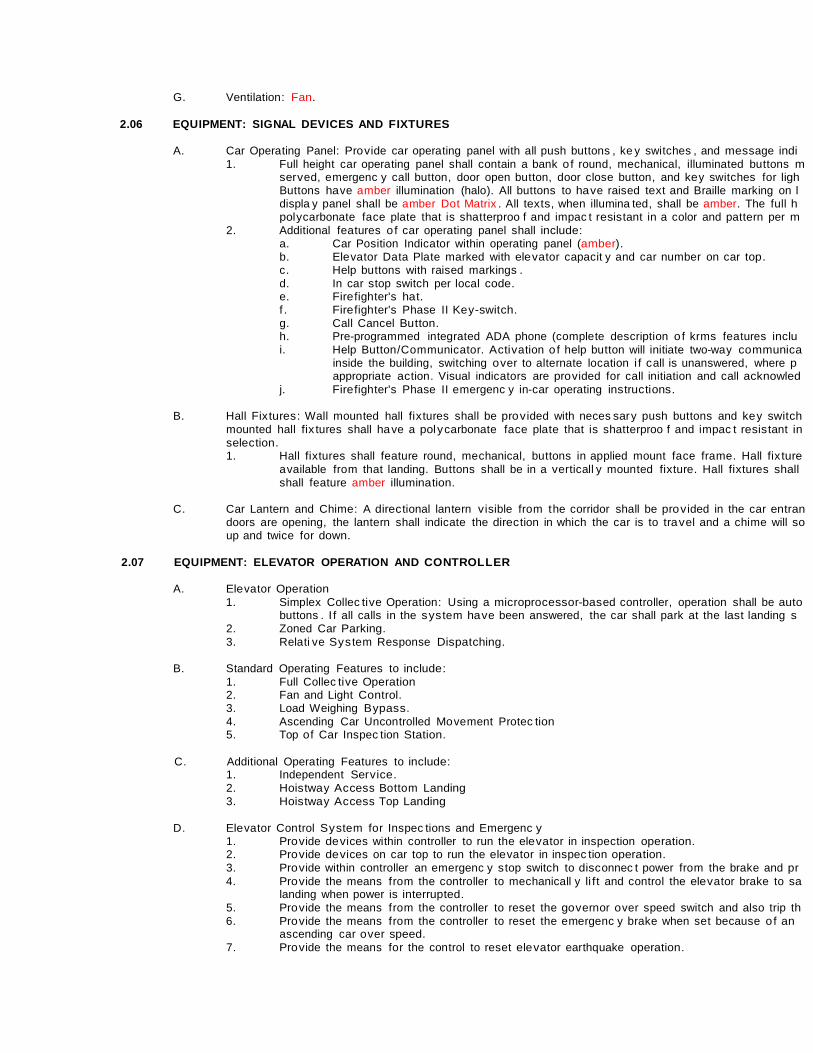
G. Ventilation: Fan.
2.06 EQUIPMENT: SIGNAL DEVICES AND FIXTURES
A. Car Operating Panel: Pro v ide car operating panel with all push buttons , ke y switches , and mes sage indi 1. Full height car operating panel shall contain a bank o f round, mechanical, illuminated buttons m
ser v ed, emergenc y call button, door open button, door close button, and ke y switches for ligh Buttons ha ve amber illumination (halo). All buttons to ha v e raised tex t and Braille marking on l displa y panel shall be amber Dot Matrix . All tex ts , when illumina ted, shall be amber. The full h pol y carbonate face plate that is shatterproo f and impac t resis tant in a color and pattern per m
2. Additional features o f car operating panel shall include: a. Car Position Indicator within operating panel (amber). b. Ele vator Data Plate marked with ele v ator capacit y and car number on car top. c. Help buttons with raised markings . d. In car s top switch per local code. e. Fire fighter's hat. f . Fire fighter's Phase II Ke y-switch. g. Call Cancel Button. h. Pre-programmed integrated ADA phone (complete description o f krms features inclu i. Help Button/Communicator. Ac ti v ation o f help button will initiate two-way communica
inside the building, switching o v er to alternate location i f c all is unanswered, where p appropriate ac tion. Visual indicators are pro v ided for call initiation and call acknowled
j. Fire fighter's Phase II emergenc y in-car operating ins truc tions .
B. Hall Fix tures : Wall mounted hall fix tures shall be pro v ided with neces sar y push buttons and ke y switch mounted hall fix tures shall ha ve a pol y carbonate face plate that is shatterproo f and impac t resis tant in selec tion. 1. Hall fix tures shall feature round, mechanical, buttons in applied mount face frame. Hall fix ture
available from that landing. Buttons shall be in a v erticall y mounted fix ture. Hall fix tures shall shall feature amber illumination.
C. Car Lantern and Chime: A direc tional lantern v isible from t he corridor shall be pro v ided in the car entran
doors are opening, the lantern shall indicate the direc tion in which the car is to tra v el and a chime will so up and twice for down.
2.07 EQUIPMENT: ELEVATOR OPERATION AND CONTROLLER
A. Ele vator Operation
1. Simplex Collec ti v e Operation: Using a microprocessor-bas ed controller, operation shall be auto buttons . I f all calls in the s y s tem ha v e been answered, the car shall park at the las t landing s
2. Zoned Car Parking. 3. Relati v e S y s tem Response Dispatching.
B. Standard Operating Features to include:
1. Full Collec ti v e Operation 2. Fan and Light Control. 3. Load Weighing B ypas s . 4. Ascending Car Uncontrolled Mo vement Protec tion 5. Top o f Car Inspec tion Station.
C. Additional Operating Features to include:
1. Independent Ser v ice. 2. Hois twa y Ac ces s Bottom Landing 3. Hois twa y Ac ces s Top Landing
D. Ele vator Control S y s tem for Inspec tions and Emergenc y
1. Pro v ide de v ices within controller to run the ele v ator in inspection operation. 2. Pro v ide de v ices on car top to run the ele vator in inspec tion operation. 3. Pro v ide within controller an emergenc y s top switch to disc onnec t power from the brake and pr 4. Pro v ide the means f rom the controller to mechanicall y li f t and control the ele v ator brake to sa
landing when power is interrupted. 5. Pro v ide the means f rom the controller to reset the go v ernor o ver speed switch and also trip th 6. Pro v ide the means f rom the controller to reset the emergenc y brake when set because o f an
ascending car o v er speed. 7. Pro v ide the means for the control to reset ele v ator earthquake operation.

2.08 EQUIPMENT: DOOR OPERATOR AND CONTROL
A. Door Operator: A closed loop permanent magnet VVVF high-per formance door operator shall be pro v ide hoistwa y doors simultaneousl y . Door mo v ement shall be cushioned at both limits o f tra v el. Elec tro-mec each hois twa y entrance to pre v ent operation o f the ele v ator unless all doors are closed and loc ked. An the car at each car entrance to pre v ent the operation o f the ele v ator unles s the car door is closed.
B. The door operator shall be arranged so that, in case o f interruption or failure o f elec tric power, the doors
within the car, in accordance with applicable code. Emergenc y de v ices and ke y s for opening doors f rom required b y local code.
C. Doors shall open automaticall y when the car has arri v ed at or is le veling at the respec ti ve landings. Do
time inter v al or immediatel y upon pres sing o f a car button. A door open button shall be pro v ided in the c button shall reopen the doors and reset the time inter v al.
D. Door hangers and track s shall be pro v ided for each car and hois twa y door. Trac k s shall be contoured to
hangers shall be designed for power operation with pro v isions for v ertical and lateral adjus tment. Hange tires and pre-lubricated sealed- for-li fe bearings .
E. Electronic Door Sa fet y De v ice. The ele vator car shall be equipped with an elec tronic protec ti v e de v ice
When ac ti v ated, this sensor shall pre v ent the doors f rom closing or cause them to s top and reopen i f th The doors shall remain open as long as the flow o f tra f f ic continues and shall close shortl y a f ter the las opening.
PART 3 EXECUTION
3.01 EXAMINATION
A. Field measure and examine subs trates , supports , and other conditions under which ele v ator work is to b
B. Do not proceed with work until unsatis fac tor y conditions are correc ted.
C. Prior to start o f Work , v eri f y hois twa y is in ac cordance with shop drawings. Dimensional tolerance o f ho
inches +2 inches . Do not begin work o f this sec tion until dimensions are within tolerances .
D. Prior to s tart o f Work , v eri f y projec tions greater then 2 inc hes (4 inches i f ASME A17.1/CSA B44 2000 then 75 degrees from horizontal.
E. Prior to s tart o f Work , v eri f y landings ha ve been prepared for entrance sill ins tallation. Traditional sill an
be required.
F. Prior to s tart o f Work , v eri f y ele vator pit has been cons tructed in accordance with requirements , is dr y forces , as indicated in appro v ed submittal. Veri f y tha t sumps or sump pumps located within pit will not i equipment.
G. Prior to s tart o f Work , v eri f y control space has been cons truc ted in accordance with requirements , with
shop drawings, including Slee ves and penetrations .
H. Veri f y ins tallation o f GFCI protec ted 20-amp in pit and adjacent to each signal control cabinet in control
3.02 PREPARATION
A. Coordinate ins tallation o f anchors , bearing plates , brac kets and other related ac cessories .
3.03 INSTALLATION
A. Ins tall equipment, guides , controls , car and ac cessories in ac cordance with manu fac turer ins tallation me
B. Properl y locate guide rails and related supports at locations in accordance with manu fac turer’s recomme drawings. Anchor to building s truc ture using isolation s y s tem to minimize trans mis sion o f v ibration to s t
C. All hois twa y f rames shall be securel y fas tened to fixing angles mounted in the hois twa y . Coordinate ins
other trades .
D. Lubricate operating s y s tem components in ac cordance with manu fac turer recommendations .
E. Per form final adjus tments , and neces sar y ser v ice prior to subs tantial completion.
3.04 CONSTRUCTION
A. Inter face with Other Work : 1. Guide rail brac kets attached to s teel shall be ins talled prior to application o f fireproo fing. 2. Coordinate cons truc tion o f entrance walls with ins tallation o f door f rames and sills . Maintain fr
equipment has been ins talled. a. Ensure adequate support for entrance attachment points at all landings . b. Coordinate wall openings for hall push buttons , signal fix tures and slee ves . Each ele
hoistwa y wall. c. Coordinate emergenc y power trans fer switch and power change pending signals as r
ele vator signal control cabinet in each group. d. Coordinate inter face o f ele vators and fire alarm s y s tem. e. Coordinate inter face o f dedicated telephone line.
3.05 TESTING AND INSPECTIONS
A. Per form recommended and required tes ting in ac cordance with authorit y ha v ing jurisdic tion.
B. Obtain required permits and pro v ide originals to Owner’s Representati ve.
3.06 DEMONSTRATION
A. Prior to subs tantial completion, ins truc t Owner’s Representati ve on the proper func tion and required dail personnel on emergenc y procedures.
END OF SECTION

II z.- I I
0[ !II; =
ili B
.---...-.......-.... "-DCCI_,- I'UXIIIUMHIIHIU
........... _, ""-' ' ""-'
""-·' n\1 ....
Llllllft&l I tN'
., I
Nalii:Foi'DJ . ......
RIGHT HAND CONTROL ROOM
A TOP LANDING ONLY ELEVATION IN HOISlWAY LOOKING
AT MACHINE SECTION IW\
PTORYI'IOit(IY0111:RS; 1lE ORCVI'RM:R1ctW11W:T'OR..Sl-Wl.IIE REIPOHIII.f.FOR'Tt£ F'CWJW!NI'J COICrTJJNS fiRD\ TOnE CO.E Efl'OF\IIItiVCATNOCOIIT1tJ ICDtE, INC CDJE8 SiAI.l.F'REYAI. ¥1tENAPPI.JCHILE
Ecospace _ I. PROJI)EAIUM, PUI&IIiiG!TWAYOFnE.SIZESDIINallnlt FIW..ICONC lAYCllT.VARIATKNIIUT NOT EXCEED 1•.(TtiStANCE·+1j 2. PR.IJmf.Mm.JATEIM'PORT fORQJI)ERAI.IPIQCETI(tG.I.IJJNG DMDERBEAMIFOR IIIL11PI.fB.EVATDRIIIIAco.oNIGSTWA'1)FRCIIIPfT' TDnEltJI
CF'TlEHOIIiTWAY.WJ NOT SPIMII«lF1.RTHERTHANAI.UMBJB'Y11'£QO\IEIWIII«J CCCEAIJTHCJUTY. RfEA:tDDF NGISIW.LEAFTER MCTM.LA.TDI OFEIWlCEl&. I. HOII'Tw.\YVENTIATlCI\IIl'W.l. BE ftVmED PER cmE.AEQ.IIfBEtml -4. PRD.ECI'IDNS IBUWG!IEVClltOIN ACCOfi».NCE'MTH COOEREQIJ!RE.:NTSSIWJ. BEIE\QB) A.TNll.wBEl.tDTl&STHAN1S DEOfEES FROMMtoll21:M'AL. .. PR(MJE.REIIO\WLE,08Ho\CQIIPI..WfT AIQ.HJAU. HOIJIYMYoPEMQNI)IETMBI TCR9 . t:EOFTHE HQIJTWAY ASREQ.IIIED.
PfUM)f TMJ UFEl..JEATTIOI!BfTIATTHE TOP, FRONTOF TIE HOIS'TWI!.Y. &. ARIWIOEFOR.J.U.aoc:KOUT /CUTOOTOFCFBit.tGITOINITAIJ.HW.P.SIIIUTTON!I,.!IIBNAI. Ati)HATQI r:u:T. 7. PfUJmE.Ae'PITfEINF'Oft:B)TOaJIT NVEJmCIILF'Dfi:EAOIRM.IMD !Il..fRN. RERREHCE.nE C*UWJTAlll.fiR>RYERTK:AI.f'ORCES..&NPI D / DR PIJIFIPUIJ:t (M£RE PSNT'Tl:O) I.OCA.TmWIIfTIII TlE PITIMYI«JTNT1FERE'Mll4 nE EiLEVATCRe;aJRI.ENT.
& f'RC7mfi!MTAIILEL GHTIM:;i FOR nE IMCHIJEIPACE¥11THAL.D1TIMJ'TUt I.OCI!.TmI THEHOIITW.\Y. f'RI:MEAUGl1T1'11m.ftE wmtNDA8Ef'M\TEGFCI PRQIECTB)a.R£XOCJMNIBKEOIJTL.ET ..TIEEl£VA PIT.
8. ErmWa.WNl.BNilfTO!IE IHTOPEN LtmlTIE EQI..IIM!f'T B NTAilS). ADEQUATE BI.PPCRT'F<:A ENTRNICEATTAatiiM IIOMSB RE:tUREDIUI..NiltG&AIJ. Fl tE>FlOORINGANJGRCU11'G ISTO BE IMrrAI.WJAFTlRTHEEN'TRMCE FRAAEIME IIITAll.BJ.
10. A PIT IJ.II)ERII MJIPL.B lh'iDELllt.EII0111RWl!IEI«r!B)CW1HEIJi'r'OOT Nil LOCA.TEN MTIU PER!CONE FIU.l.LA.WIIT DRAWINIIl 11. ANH1E1W.PfiM(B)ln'tca.E.III.IIT IE.INBTAUfD lllnE ElfVATOR t«JJITWA'fa.t:RtE/DPB\nEICDfE FlNI\L.lAYOOT DM'MNGIL 12. FCRPRDPEREQJJPII::NT'IJFIERATION;Tr£YA£HI£CFWEAT'Tt£TDPOFTHE YMlBTEPACJIERLY\9fTBJPEROODEREQLIIDEN11.
IMX.AI.l.CMEDH.MXTY EIIJIIIi NG.HIJII'TW\YIIJBTMAJNTAINA TEW'BUI.TUIEIIETWEEN41FNCI1D4 F. 13. THE ACCESS DOCI':TDTHE CONTRa..SPA(;ORTHECQHTIQ. AOCIII UUBTE.SE<lJIB>NaAIIIITUNAIJ'TH)Rl2B)AaES!l
ITtiWJ,IEIJELFI..OCKINIIMD.SELFO..O.NQ. 14. PRCMIEA 15-MF tazvN:.FIJIIED BERYICE WITH GRCUI)(W,BIERGEfCYUGJiTaiPPLYIF AYAI.AII.E) CCNEC'T'EOTn E.IGH CDtfTRCl. CABINETFOR
lJCimNQAtl) FAN. PRCMDE CEDICATB)PHQIIE IJIETBMMilNQATTI-E ELEVATORCCNTRCI. CAllE. 15. F<l\cotmii.IIWBLOCATmREIIIOTELYFRCIIInEElfWI'l'tRtmTWAY.fJRCMCEAGCM:RNCI\M:CBI OFIEZEAN[) lu.PB\
KOtE FNM. LAvaJTIJRAWIINOI. THEACI:HI!I DOCI':SIAI.l.IESIED.A:D ACX::EU. 11. IWMIEAS.UAIII.E'ti'CRQG BWRXWENTII«lJ.lltiiGI«QJATEIOZS!!ITOT'rt:BUILD!l'ftCI'ER L.DfT1NG 1\114J.MEN5,a.EMMDIN'E
.srcJW)[AD.WDfTnTHE HOIBl'tMY,"'Dil.FRaEHTCN8TERERJGECIJITAII'&IFDRTHEDIFOIW. OF B.£YAflllaCINO MATEIIAI..S. 17. TH.IIIAWINI311ATIE f&1CWEIJMO IIY ALICEN:IiDfiROFESSIONAL lOCNSI.RECOIRIANCE'MlltI..OCAI-BULDI<! coa:8. 11. THE&E.DRAMGSARE FDRI TlON PI.JUIOIESCIIILY NCIIIJSTNOTEE UIIED RRCONmliCTDI PUFFCEI. Rll.YIETAI.B)
CONSnWC'TlONDRAWINQIARE L.Aalf FRCI.ITJE PACD.CI' u.w.JFJ.C'T\HR.
SPECIFICAmNS P...fm...i.:.r_.N.M, E: ICOIE_EOOi!PM:E-TOR
CNJIQTY:3500lBB (15MKG) &PEED: 1IJIFRII DCXR: L.EFTOPEIIItG 1RAE.: ., CONTRa.t..OCATDI: INTmfW.a.DIET POWERilFPI.Y: D REQLI/e) Fla:AAF8: 35 CON'TRCI.LSIHEATOOI'l'Vt.U IUICH•CHCATOI.m"UT:1.IICirTU'I+1
BUI.Dt'IIG(I'ftQB;TMIIE) HOOOIWIHQZO
1"""'111< c:w.J.lP,
MiiiinRir BIFfOII)+CAl.OTT
1- B«!..EER r. ,.
D......., [HET
'"
,
--------------------------------------------------------------------------------------I
SCALE:NOT TOSCALE =mDMWI GE lB)UUGPNWETRX"''EQHl.CQt'

SECTION 21 13 00 - FIRE SUPPRESSION SYSTEM PART 1 GENERAL
1.1 REQUIREMENTS:
A. Conform to applicable provisions of the General Conditions, Special Conditions and the General Requirements. The Contractor must design, install and have a Fire Protection Engineer stamp the design drawings.
B. See Division 26 for electrical work.
1.2 RELATED SECTIONS: A. See Section 230000. B. See Section 221000.
1.3 SCOPE A. The design and installation of an automatic fire protection system with sprinkler heads, controls, inlet
connections, test and drain connections, zone flow switches, tamper switches, valves, fittings, pipes and all other necessary accessories required for a complete and properly operating system. The contractor shall be fully aware of the building design and all areas requiring fire protection. Failure to not be knowledgeable of the building will not be cause for additional charges.
B. This contractor will be responsible to size the incoming service, which shall include any proposed future addition as shown on the attached drawing(s) and will be responsible for connection to the water main and extension into the building.
C. The design and installation of the system shall conform to the all applicable requirements of the building and backflow prevention codes of the State of New Mexico and to the applicable provisions of NFPA Standards Nos. 13, 24 and Life Safety Code 101. Where these specifications exceeding standards of above listed codes, than these specifications shall be followed.
D. Also requirements of owner insurance and authorities having jurisdiction shall be incorporated in design. E. The work included in this contract consists of furnishing all labor, materials, equipment, tools and
services, and includes all costs of permits and all costs whatsoever which may be required to install complete, properly working systems as described herein. All system components shall be standard product of the latest design of the manufacturer.
F. Provide temporary fire protection during construction as required by the Building Code and the Fire Marshal.
1.4 SHOP DRAWINGS AND CALCULATIONS
A. See Section 230000 for general submittal requirements. B. The Contractor shall submit shop drawings of the complete fire protection system to the Architect for
review. Fire protection system shop drawings shall be submitted first for review and approval by the local authorities having jurisdiction and after receiving stamped approval shall be submitted to the Architect for his review. No construction work shall begin or equipment purchased without the written approval of the Architect and engineer of record.
C. Shop drawings shall include complete data as required by NFPA 13 Chapter 6, description of all equipment and materials to be furnished including performance, quality, dimensions and certifications of approving agencies. Complete drawings of the system shall be submitted including plot plan showing location and arrangement of water supply connection, control valve, fire department connections, on- site fire main routing, on-site fire hydrants and other equipment to be used; and including head layouts coordinated with lighting, plumbing and air conditioning system. Shop drawings must be stamped by a New MexicoFire Protection Engineer.
D. The hydraulic calculations shall be based on worst condition of available water pressure. Summer pressure drop in water mains in time of high irrigation demand shall be addressed. In case of double water source (such as on site storage tank), the lowest available pressure shall be taken for calculating base, unless specifically (in writing) allowed by the Owner’s- insurance and/or the Engineer.
E. The hydraulic calculations shall show minimum of 10% extra pressure for unexpected job site modifications of the system. This requirement is in addition to “worst available” water pressure as described in paragraph above.
F. The hydraulic calculations shall be based on area/density method. Room design method or pipe schedule sizing may be used only if specifically approved by the engineer.
G. Throughout the system the velocity shall not exceed 20 feet per second.
SECTION 21 13 00 - FIRE SUPPRESSION SYSTEM 1

1.5 ELECTRICAL CONNECTIONS
A. A. Electrical connections from devices and components including water-flow indicators, tamper switches, etc., furnished and installed under this section to the building fire alarm system shall be wired under Division 26 or Section 283100.
1.6 GUARANTEE-WARRANTY
A. The following guarantee is a part of the specifications and shall be binding on the Contractor. B. The Contractor guarantees that this installation is free from mechanical defects. He agrees to replace or
repair to the satisfaction of the Architect any part of the installation which may fail within a period of one (1) year after date established below, provided that such failure is due to defects in the materials and workmanship or to failure to follow the specifications and drawings. Warrant of the Contractor furnished equipment or systems shall begin on the date the system or equipment is placed in operation for beneficial use of the Owner or occupancy by the Owner, whichever occurs first.”
1.7 CONTRACTOR QUALIFICATIONS
A. ConTractor for the installation of the fire protection systems specified herein shall be duly licensed and
regularly engaged in the installation of automatic sprinkler equipment as listed by Underwriters Laboratories, Inc., or other nationally recognized testing laboratories.
1.8 SERVICE CONNECTION - WATER SERVICE
A. The connection to water service main and service line for the fire protection system shall be provided as indicated on the Drawings and shall be furnished and installed by the Contractor complete including all required backflow prevention or detection devices (if they are required by the local applicable codes and regulations).
1.9 ALARM FACILITIES
A. Equipment necessary to accomplish the required water-flow alarm shall be furnished and installed under this section of the specifications. Water-flow detection devices shall consist of approved water- flow indicators as specified herein.
B. Local alarm shall consist of an approved alarm check valve with complete trim and mechanical water motor alarm gong. Use of electrical audible alarm bell, shall be prior approved. All alarm devices shall be furnished by the Contractor and wired under Division 283100 Fire Alarm System (location of alarm bell or gong as approved or directed by the Architect).
C. Water-flow indicators tamper switches and other required sprinkler system alarm functions shall be integrated into the building fire alarm system under Section 283100. The Contractor shall coordinate with Section 283100, Fire Alarm Systems, in order to establish exact requirements and location of items provided under this section, which require connections to the fire alarm system.
PART 2 PRODUCTS
2.1 PIPING
A. Underground outside of building, see drawings. B. Underground inside of building: Class 200 ductile iron with mechanical-restricted joints. Interior of pipe
and fittings shall be cement lined. C. Building Interior Piping System:
Pipe shall be new, designed for 175 PSI or system maximum working pressure, conforming to ASTM specifications, and have the manufacturer’s name or brand along with the pipe applicable ASTM Standards marked on each length of pipe. 1. Pipe shall be steel, Schedule 40, black and in accordance with specifications ASTM A 135, and
A 53. 2. Pipe shall be steel, Schedule 10, black and in accordance with specification ASTM A 135. 3. Tubing shall be copper, Type K, L, or M, suitable to withstand water working pressure not less
than 175 PSI, and in accordance with specification ASTM B 75 or ASTM B 88. 4. Other steel pipe shall be Underwriters Laboratories Inc., “LISTED”, and Factory Mutual Systems
“APPROVED”, exterior galvanized, ASTM A-I 35 steel pipe. It shall be joined by screwed joints in accordance with specification ANSI B 2.1 (ANSI B 1.20.1 - 1983) per NFPA No. 13, Section 3- 12.1.1, or by welded joints in accordance with specification ANSI B 31.1 as amended or by NFPA No. 13 approved mechanical fittings. Couplings may be of 2243.
21 13 00-2

2.2 SPRINKLER HEADS
A. Provide sprinklers in accordance with NFPA Standard 13. Rooms with suspended ceilings shall be protected with chrome plated pendent sprinklers and two piece semi-recessed chrome-plated escutcheon plates.
B. Areas without ceilings shall be protected with brass upright sprinkler heads. In the event that conditions prohibit upright heads, brass pendant heads may be installed provided they are equipped with guard cages.
PART 3 EXECUTION
3.1 INSTALLATION
A. The contractor shall install a fire-protection water supply main complete with connection to existing water supply main. The trenching and backfill of these lines shall be as defined elsewhere in these specifications. No installation will be permitted prior to approval of complete shop drawings.
3.2 CONSTRUCTION
A. Contractor shall be responsible for taking the following fire precautions during the construction of the building, prior to the sprinkler system being in operation: 1. General good housekeeping procedures should be followed so that accumulations of debris and
rubbish will not become a hazard. 2. All temporary heating equipment and open flame devices shall be properly supervised. 3. Smoking should be controlled and permitted only in specified areas.
3.3 CORDINATION WITH OTHER TRADES A. The Contractor shall carefully lay-out piping and sprinklers to avoid air conditioning equipment, ducts,
lights and structure. Offset drops as required for coordination.
3.4 TESTS A. Upon completion, and prior to the acceptance of the installation, the Contractor in the presence of the
Architect or his duly-appointed representative, shall subject the system to the tests required by NFPA Pamphlet No. I 3A, and shall furnish the Owner with a certificate as thereby required.
3.5 STERILIZATION
A. All new lines shall be flushed and sterilized with chlorine before acceptance for service. Calcium
hypochlorite powder, containing not less than 70% available chlorine, shall be used for sterilization. The amount of chlorine applied shall be such as to provide a dosage of 40- 60 PPM for at least twenty-four hours. At the conclusion of the twenty-four hour contact time, CL2 residual should be at least 20 PPM. The chlorinating material shall be mixed with treated water in an acceptable container and injected directly into the system, the process being repeated until the system is filled. All valves in the system shall be opened and closed three times during the procedure to insure that the sterilizing mixture is thoroughly and evenly distributed throughout the system.
3.6 FINAL FLUSHING
A. After the application retention period, the Architect-Engineer shall determine the chlorine content of the
source of supply. The heavily chlorinated water in the new system shall be flushed until the chlorine concentration is not higher than that of the source.
3.7 AS-BUILTS
A. The Contractor shall furnish “As-Built” drawings on reproducible mylar and CAD drawings on a compact
disk. The drawing shall be produced utilizing AutoCAD “dwg” file format. A base sheet with the title block and building floor plan will be supplied to the fire protection contractor upon request. The drawing file will be a product of AutoCAD latest release.
END OF SECTION 21 13 00
SECTION 21 13 00 - FIRE SUPPRESSION SYSTEM 3

1 SECTION 22 10 00 - PLUMBING BASIC MATERIAL AND METHODS
SECTION 22 10 00 - PLUMBING BASIC MATERIAL AND METHODS
PART 1 GENERAL
1.01 RELATED DOCUMENTS A. Drawings and general provisions of the Contract, including General and Supplementary Conditions and
Division 1 Specifications sections, apply to work of this section. B. Related sections: Refer to “Section 23 00 00, HVAC General Mechanical Requirements” for basic
requirements of all work.
PART 2 PRODUCTS
2.01 PIPING GENERAL A. Steel: ASTM A- 120, Schedule 40 B. Copper: ASTM B- 88 C. Cast Iron: CISPI HS-67 or CISPI 301-67-T D. PVC: ASTM D 2321 (Sewer and Gravity flow)
2.02 FITTINGS
A. Malleable Iron: ANSI B 16.3 B. Cast Iron: ANSI B16.4 C. Wrought Copper: ANSI B 16.8 or ANSI B 16.22 D. Weld Fittings: ANSI C 16.9
2.03 JOINTS
A. For Cast Iron Pipe: ASTM C-564 double seal elastromeric compression-type gaskets, or CUSP 301, 67T, no-hub joint.
2.04 UNIONS A. For Ferrous Pipe: Federal Specifications WW-O- 531-a- Stockman, No. 695. B. For Copper Pipe: Federal Specification WW-U-516-Nibco 633. C. Dielectric Unions: Provide dielectric unions with appropriate end connections for the pipe materials in
which installed (screwed or Soldiered), which effectively isolate dissimilar metals, prevent galvanic action, and stop corrosion.
D. Dielectric Waterway Fittings: Electroplated steel or brass nipple, with an insert and non-corrosive, thermoplastic lining.
2.05 PIPE THREADS
A. ASA B2.1
2.06 HANGERS A. Federal Specifications WW-H-171. Fee and Mason, Grinnell Company, or approved equal. Sectional
expansion hangers with turnbuckle and beam clamps, ceiling or insert plates, or lag screws, as required.
2.07 SHEETS
A. Galvanized Steel: ASTM A-525 B. Lead: Federal Specifications QQ-1-206, Grade B
2.08 VALVES
A. See individual sections.
2.09 FLOOR, WALL AND CEILING PLATES
A. Shall be chrome plated pressed or stamped brass, either one piece or split pattern held in place by internal spring tension or set screw.
2.10 MISCELLANEOUS PIPING MATERIALS/PRODUCTS
A. Welding Materials: Except as otherwise indicated, provide welding materials as determined by Installer
to comply with installation requirements. 1. Comply with Section II, Part C, ASME Boiler and Pressure Vessel Code for welding Materials.
B. Brazing Materials: Except as otherwise indicated, provide brazing materials as determined by Installer to comply with installation requirements. 1. Comply with SFA-5.8, Section II, ASME Boiler and Pressure Vessel Code for brazing filler metal
materials.

2 SECTION 22 10 00 - PLUMBING BASIC MATERIAL AND METHODS
C. Soldiering Materials: Except as otherwise indicated, provide Silver Brite 100 solder.
2.11 INSULATION A. Pipe and equipment insulation shall conform to Underwriters Laboratories 40, U.15.19 “Pipe and
Equipment Cover Systems”. Ductwork insulation lining and adhesives shall conform to NFPA 90A, and shall be U/L Class 1.
2.12 SLEEVES
A. Steel Sleeves: Schedule 40 galvanized, welded steel pipe shall be utilized for pipe passing through masonry or concrete construction.
B. Sheet metal Sleeves: 10 gauge, galvanized sheet metal shall be utilized for ducts passing through masonry or concrete construction for pipes and ducts passing through finished partitions of ceilings.
2.13 PIPING SPECIFICATIONS
A. Sanitary and Waste Lines: 1. All lines underground shall be standard cast iron compression type gaskets. Lines above
ground shall be standard weight compression joint or no-hub joint. B. Sanitary Vent Piping:
1. Sanitary vent piping shall be service weight no-hub cast iron. C. Water Piping in the Building:
1. Type L hard drawn copper water tubing for above grade installation. Piping in the ground shall be copper type K tubing with no below slab joints.
D. Gas Piping: 1. Gas piping shall be schedule 40, screwed black steel. Underground piping and exterior exposed
piping shall have a protective coating. Protective covering on the underground pipe shall be mechanically applied in a factory of field plant especially equipped for the purpose, except as hereinafter indicated. Specials and fittings which cannot be coated mechanically shall have the protective covering applied by hand. Hand applied covering shall equal in coating thickness and effectiveness to that of mechanically applied covering. The pipe covering material shall be Scothkote No. 101 pipe coating resin, as Manufactured by the Minnesota Mining and Manufacturing CO., or X-Tru Coat as manufactured by Standard Pipe Protection , Inc.
2.14 VALVES
A. General: 1. Furnish and install valves at the inlet and outlet of each piece of equipment, ahead of all control
valves and at all places shown on the drawings. All shut off type valves shall be ball valves unless otherwise indicated.
2. All ball valves shall be full port, line size equal to Conbraco Apollo 77-200 Series. B. Domestic Water Lines
1. Valves shall be equal to Type 3" and Smaller
Ball valve Conbraco Check valve Crane #1303 Plug cocks DeZurik #427
C. Gas Service: 1. Valves shall be similar and equal to DeZurik conforming to specification D-ASA B-31.8 for gas
transmission and distribution piping.
2.15 V-TYPE STRAINERS A. Provide strainers full size of connecting piping, with body and ends to match piping system materials.
Screen shall be Type 304 stainless steel, with 3/64" perforations at 233 per square inch.
2.16 AIR CHAMBERS A. Air chambers shall be 18" long and the same diameter and material as the supply, with caps and shall be
provided on all hot and cold branches of every plumbing fixture. All air chambers shall be concealed in the partitions. Where piping is exposed, air chambers shall be close to faucet or open-closing device. Shock absorbers are an acceptable alternate.
2.17 EXPANSION AND CONTRACTION
A. Provide for expansion and contraction of all piping, using expansion joints, swing joints, ball joints, bends, or other approved methods. Furnish anchors, when necessary, to prevent movement of pipe. All anchors shall be separate and independent of all hangers and supports, and shall be designed of heavy fabricated steel to prevent movement of pipe under the stresses encountered. Shop drawings shall be submitted showing location of all anchors, expansion joints, ball joints, etc.

3 SECTION 22 10 00 - PLUMBING BASIC MATERIAL AND METHODS
PART 3 EXECUTION
3.01 DELIVERY, STORAGE, AND HANDLING
A. Except for hub-and spigot, and similar units of pipe, provide factory applied plastic end caps on each length of pipe and tube. Maintain end-caps through shipping storage and handling as required to prevent pipe-end damage and to eliminate dirt and moisture of pipe or tube.
B. Where possible, store pipe and tube inside, protected from the weather. Where it is necessary to store outside, elevate above grade and enclose with durable, waterproof wrapping.
C. Protect fittings from moisture and dirt by inside storage and enclosure, or by covering with durable, waterproof wrapping.
3.02 INSTALLATION
A. The installation shall be in conformity with best practice and shall contribute to the efficiency of the operation, accessibility, sightlessness, and efficient maintenance. Installation shall conform to codes and standard of the National Engineering Societies applicable, to the manufacturer’s recommendations, and shall also conform to the building structure, structure, equipment and usage. No part of the installation shall interfere with the operation of any other systems or operational part of the building. The drawings show the general design, arrangement, and extent of the system, and shall not be scaled for rough-in-measurements or used as shop drawings.
3.03 PIPING
A. Provisions for Drainage: All piping systems shall be installed so that they may be easily drained. Drain caps, plugs, of drains, shall be installed at low points.
B. Alignment: All installed pipes shall be straight and have no strains. Proper allowance shall be made for expansion and contraction.
C. Clean as installed: All piping must be clean and free from scale or loose dirt when installed and must be kept clean during the completion of the installation. All openings in the piping system shall be capped or plugged while awaiting further connections.
D. Welding Black steel pipe one inch and larger shall be welded according to the American Standard Code for Pressure Piping, ASA B-31.1, using standard welding fittings. No notching or mitering of pipe will be accepted. Welding shall be done by certified welders meeting the qualification of the Heating, Piping, and Air Conditioning Contractor’s National Association.
E. Soldering and Brazing: Soldering and brazing shall conform to ANSI - B .1 Standard safety code for Mechanical Refrigeration.
F. Bending: No bending of piping will be permitted. G. Electrical Equipment Spaces: Do not run piping through transformer vaults and other electrical
equipment spaces and enclosures.
3.04 PIPING SYSTEM JOINTS A. Thread pipes in accordance with ANSI B 2.1; cut threads full and clean using sharp dies. Ream threads
ends to remove burrs and restore full inside diameter. Apply pipe joint compound, or pipe joint tape (Teflon) where recommended by pipe/joint manufacturer, on male threads at each joint and tighten joint to leave not more than three threads exposed.
B. Braze copper tube-and fitting joints where indicated, in accordance with ASME B 31. C. Solder copper tube-and fitting joints where indicated, in accordance with industry practice. Cut tube
ends squarely, ream to full inside diameter, and clean outside of tube ends and inside of fittings. Apply solder to flux to joint areas of both tube and fitting. Insert tube full depth into fitting and solder in a manner which will draw solder full depth and circumference of joint. Wipe excess solder from joint before it hardens.
D. Mechanically Formed Tee Connections: In lieu of providing tee fittings in the copper tubing. Installer may, as an option, provide mechanically formed tee connections, providing they are in accordance with the following: 1. Size and wall thickness of both run tube and branch tube are listed by the Manufacturer of
forming equipment as “Acceptable Application”. 2. Height of drawn collar is not less than three times wall thickness of run tubing. 3. End of branch tube is notched to conform to inner curve of run tube, and dimpled to set exact
penetration depth into collar. 4. Resulting joint is minimum of three times as long as thickness of thinner joint member, and
brazed using B-CUP series filler metal. E. Mechanically Formed Couplings: In lieu of providing couplings in copper tubing, Installer may, as an
option, provide mechanically formed couplings, provided they are in accordance with the following:

4 SECTION 22 10 00 - PLUMBING BASIC MATERIAL AND METHODS
1. Form couplings by first annealing area at the end of the tube where expansion will occur. Insert the tube expander to die size and expand the tube end to accept tubing of the same size.
2. Resulting joint must be a minimum of three times as long as the thickness of the tube, and brazed using B- CUP series filler metal.
F. Weld pipe joints in accordance with recognized industry practice and as follows: 1. Weld pipe joints only when ambient temperature is above 0 deg. F. 2. Bevel pipe ends at a 37.5 deg. Angle, smooth rough cuts, and clean to remove slag, metal
particles and dirt. 3. Use pipe clamps or tack-weld joints with 1" long welds; four welds for pipe sizes to 10", eight
welds for pipe sizes 12" to 20". 4. Build up welds with stringer-bead pass, followed by hot pass, followed by cover or filler pass.
Eliminate valleys at center and edges of each weld. Weld procedures which will insure elimination of unsound or unfused metal, creaks, oxidation, blow-holes, and non-metallic inclusions.
5. Do not weld piping system imperfections by tack-welding procedures, prefabricate to comply with requirements.
6. At Installer’s option, install forged branch-connection fittings where ever branch pipe is indicated; or install regular “T” fitting.
G. Hubless Cast-Iron Joints: Comply with coupling manufacturer’s directions.
3.05 DUCTWORK A. All ductwork shall be rigidly supported by the building structure, using strap hangers. All ducts, diffusers,
and grilles and connected equipment shall be clean when installed and kept clean until the system is completed. All ducts shall be properly flashed and counter flashed.
3.06 UNIONS
A. Install a union on the down stream side of all shut-off valves, at equipment connection, where needed for disassembling of piping and where shown on the plans.
3.07 HANGERS
A. Hangers for all piping shall support the pipe without piercing the insulation. Insulated shields shall distribute the load so that it will not crush, compress, or deform the insulation. Piping shall be anchored where required to localize expansion or to prevent undue strain on piping and branches. Vertical risers shall be supported at four feet on center. Hangers for steel pipe shall be spaced at 6' - 0" o.c. for pipes 1" and smaller, 9'-0" o.c. for pipes 1 1/4" to 2"; 10'-0" o.c. for larger pipes. Copper tubing shall be supported at 6'-0" o.c. for piping 1 1/2" and smaller and 10'-0' o.c. for piping 2" and larger. Cast iron pipe shall be supported 4'-0' o.c. Use of plumber tape or chains will not be allowed.
3.08 ISOLATORS
A. All rotating equipment or apparatus shall be isolated form the structure by vibration isolation devices and from piping by flexible connection. Use Mason Industries Type NK pads, unless otherwise indicated on the drawings.
3.09 SUPPORTS
A. Support piping independently at pumps, tanks, etc., so that the weight will not be supported by the equipment.
3.10 FLOOR, WALL, AND CEILING PLATES
A. Provide throughout the building for all pipes in all furnished rooms.
3.11 INSULATION A. Shall be continuous throughout walls, partitions, floors, and ceilings.
3.12 CLEANING, FLUSHING, AND INSPECTION
A. Clean exterior surfaces of installed piping system of superfluous materials, and prepare for application of specified coatings (if any). Flush out piping systems with clean water before proceeding with required tests. Inspect each run of each system for completion of joints, supports, and accessory items.
B. Disinfect water mains and water service piping in accordance with Section 3.16, 22 11 00, and/or AWWA C601.
3.13 IDENTIFICATION TAGS AND LABELS

5 SECTION 22 10 00 - PLUMBING BASIC MATERIAL AND METHODS
A. Pipe Labels: Pipe labels shall be self adhesive labels, all-temporary Permacode pipe markers no. B- 500, manufactured by W.H. Brady Company.
B. Tags: Tags shall be aluminum, brass or laminated plastic 2"x 1" minimum with edges ground smooth or rolled. Each tag shall be punched to receive a chain. Letters and numbers shall be evenly spaced and stamped or engraved into the surface.
C. Equipment Labels: Engraved plastic-laminate signs shall be melamine plastic laminate six inches long by three inched high by 1/8 inch thick. The lettering shall be block type with 1 - ½ inch height. 1. Laminate core color shall be white. 2. Laminate face colors shall be color treated as follows:
a. Green: Cooling equipment and components b. Yellow: Heating equipment and components c. Blue: Equipment and components that do not meet any of the above criteria
D. Installation of piping: Bare pipes to be marked shall first be wiped clean of dirt, dust, grease, and moisture. Markers to be installed on painted piping shall be applied only after completion of the final coat of paint. Insulated piping shall be painted to a smooth, hard surface in the area the label is to be applied. Labels should be applied, using pressure, so that it lies smooth and flat. After application on insulated pipes, the labels shall be stapled securely to the insulation. A brush coat of clear lacquer shall be applied and the lettering positioned to be legible. For overhead piping, apply markers on the lower half of the pipe where view is unobstructed, so that markers can be read from floor level. The wording on the labels shall correspond directly to that on the Mechanical symbols list, regardless of manufacturer. 1. Use an arrow marker with each pipe-content marker. The arrow shall point away from the pipe
marker and in the direction of flow, with background color and height the same as the content marker. If flow can be in both directions, use two arrows.
2. Apply pipe marker at each valve, at every point of entry or exit through wall or ceiling, on each riser and branch of tee, and every twenty feet on long continuous lines or at every bay or aisle to show proper identification of pipe content and direction of flow.
E. Installation of valves: Valve tags shall be attached to the valve handle with brass chain. All main service valves shall be tagged and identified as to the type of service. All ball valves, gate valves or stop cocks controlling branch mains or risers shall be tagged and identified as to the areas served.
F. Installation on Equipment: All major pieces of equipment shall be identified with an engraved plastic- laminated sign. Each piece of equipment requiring a sign shall be thoroughly cleaned prior to installing the label. Plastic-laminated signs shall be attached by self-taping stainless steel screws, except contact-type permanent adhesive or where screws cannot or should not penetrate the substrate.
END OF SECTION 22 10 00 - PLUMBING BASIC MATERIAL AND METHODS
SECTION 22 11 00 - FACILITY WATER DISTRIBUTION 1
SECTION 22 11 00 - FACILITY WATER DISTRIBUTION
PART 1 GENERAL
1.01 RELATED DOCUMENTS: A. Drawings and general provisions of Contract, including General and Supplementary Conditions and
Conditions and Division 1 Specifications, apply to work of this section. B. Related Sections: Refer to Sections 22 10 00 and 23 00 00 for requirements for all mechanical work.
1.02 SCOPE
A. Complete system including connection to the water supply outside of the building, service lines and connection to all plumbing fixtures and outlets. Contractor is responsible for layout, verification and installation of a complete and operating water system, from service connection to fixtures.
PART 2 PRODUCTS
See Section 22 10 00 “Plumbing Basic Materials and Methods” for Material Specifications.
2.01 GENERAL PRODUCTS A. Available Manufacturers: Subject to compliance with requirements, manufacturers offering products
which may be incorporated in the Work include, but are not limited to: 1. Basket Strainers:
a. Josam Mfg. Co. b. Metraflex Co. c. Sarco. d. Smith (Jay R.) Mfg. Co.
2. Balance Cocks: a. American Air Filter Co. b. Bell & Gossett ITT; Fluid Handling Div. c. Hammond Valve Corp. d. Milwaukee Valve Co., Inc. e. Spirax Sarco. f. Taco, Inc.
3. Bibbs and Faucets: a. Hammond Valve Corp. b. Lee Brothers; Div. Phelps Dodge Brass Co. c. Mansfield Plumbing Products. d. Nibco Inc. e. Prier Brass Mfg. Co. f. Tanner Mfg. Co. g. Woodford Mfg. Co.
4. Hydrants: a. Josam Mfg. Co. b. Smith, (Jay R.) Mfg. Co. c. Tyler Pipe; Sub. of Tyler Corp. d. Woodford Mfg. Co. e. Zurn Industries Inc., Hydromechanics Div.
5. Backflow Preventers: a. Febco Sales, Inc.; Subs. of Charles M. Bailey Co., Inc. b. Hersey Products, Inc. c. ITT Lawler; Fluid Handling Div. d. Watts Regulator Co.
6. Pressure Regulating Valves: a. Cash (A. W.) Valve Mfr. Corp. b. Cla-Val Co. c. Spence Engineering Co., Inc. d. Watts Regulator Co.
7. Relief Valves: a. Cash (A. W.) Valve Mfg. Corp. b. Conbraco Industries, Inc. c. Watts Regulator Co. d. Zurn Industries, Inc.; Wilkins-Regulator Div.
8. Water Hammer Arresters: a. Amtrol, Inc. b. Smith (Jay R.) Mfg. Co. c. Tyler Pipe; Sub. of Tyler Corp.

SECTION 22 11 00 - FACILITY WATER DISTRIBUTION 2
d. Zurn Industries, Inc.; Hydromechanics Div. 9. Dielectric Waterway Fittings:
a. Victaulic Company of America 10. Dielectric Unions:
a. Perfection Corp. b. Watts Regulator Co.
11. Y-Pattern Strainers: a. Armstrong Machine works. b. Hoffman Specialty ITT; Fluid Handling Div. c. Metraflex Co. d. Spirax Sarco. e. Trane Co. f. Victaulic Co. of America. (low pressure applications only) g. Watts Regular Co.
B. Pipe and Tube Materials: 1. General: Refer to Part 3, Article "Pipe Applications" for identification of systems where the below
materials are used. 2. Drawn Temper Copper Tubing: ASTM B88, Type L. 3. Annealed Temper Copper Tubing: ASTM B88, Type K.
C. Fittings: 1. Wrought-Copper Fittings: ANSI B16.22, streamlined pattern. 2. Cast Bronze Flanges: ANSI B16.24, Class 150; raised ground face, bolt holes spot faced. 3. Unions: ANSI B16.39, malleable iron, Class 150, hexagonal stock, with ball-and-socket joints,
metal-to-metal bronze seating surfaces; female threaded ends. Threads shall conform to ANSI B1.20.1.
4. Dielectric Unions: Threaded or soldered end connections as required to suit application; constructed to isolate dissimilar metals, prevent galvanic action, and prevent corrosion.
D. Joining Materials: 1. Solder Filler Metals: ASTM B 32, 95-5 Tin-Antimony. 2. Gasket Material: Thickness, material, and type suitable for fluid to be handled, and design
temperatures and pressures. E. General Duty Valves:
1. Special duty valves are specified below by their generic name refer to part 3, Article "Valve Application" for specific uses and applications for each valve specified.
F. Piping Specialties: 1. Water Hammer Arresters: Bellows type with stainless steel casing and bellows, pressure rated
for 250 psi, tested, certified, sized and located in accordance with PDI Standard WH-201. 2. Basket Strainers: Cast-iron body with 125 psi flanges, bolted type or yoke type cover; with
removable non-corrosive perforated strainer basket having 1/8 inch perforations and lift-out handle.
3. Hose Bibbs: Bronze body with renewable composition disc, tee handle, 3/4 inch NPT inlet, and 3/4 inch hose outlet.
4. Sill Faucets: Bronze body with renewable composition disc, wheel handle, 3/4 inch NPT inlet, and 3/4 inch hose outlet.
5. Recessed Non-Freeze Wall Hydrants: Cast-bronze box with chrome plated face, tee handle key, vacuum breaker, hinged locking cover, 3/4 inch inlet, and hose outlet. Bronze casing length shall suit wall thickness.
6. Projecting Non-Freeze Wall Hydrants: Cast-bronze, with chrome plated face, tee handle key, vacuum breaker, 3/4 inch inlet, and those outlet. Bronze casing length shall suit wall thickness.
7. Floor Level Non-Freeze Hydrants: Cast-bronze hydrant with rough bronze box, tee handle key, drain hole, vacuum breaker, hinged locking cover, 3/4 inch inlet, and hose outlet. Bronze casing length shall suit wall thickness.
8. Non-Freeze Post Hydrants: Cast-bronze hydrant with level action control, drain hole, vacuum breaker, 3/4 inch inlet, and hose outlet. Bronze casing with cast-iron casing guard shall be length to suit depth of bury.
9. Backflow Preventers: Reduced pressure principal assembly consisting of shutoff valves on inlet and outlet, and strainer on inlet. Assemblies shall include test cocks, and pressure-differential relief valve located between TWO (2) positive seating check valves, and comply with requirements of ASSE Standard 1013.
10. Pressure Regulating Valves: Single seated, direct operated type; having bronze body with integral strainer, and complying with requirements of ASSE Standard 1003. Select proper size for maximum flow rate and inlet and outlet pressures indicated.
11. Relief Valves: Provide proper size for relief valve, in accordance with ASME Boiler and Pressure Vessel Codes, for indicated capacity of the appliance for which installed.
12. Combined Pressure-Temperature Relief Valves: Bronze body with test lever, thermostat, complying with ANSI Z21.22 listing requirements for temperature discharge capacity. Provide

SECTION 22 11 00 - FACILITY WATER DISTRIBUTION 3
temperature relief at 210°F, and pressure relief at 150 psi.
2.02 PIPES A. Domestic water distribution and piping including cold water, hot, water, and recirculating water lines
shall be type “L” hard drawn copper tubing with soldiered wrought copper fittings. Solder shall be Silverbrite 100.
B. Below grade water distribution piping beneath the building shall be type “ K” softdrawn copper tubing with no joints allowed.
C. Below grade water service line shall be type ”K” hard drawn copper tubing with brazed wrought copper fittings.
D. Pipe exposed in finished rooms shall be chromium plated.
2.03 MISCELLANEOUS A. All shut-off valves shall be full port valves unless otherwise indicated. B. Escutcheons shall be chrome plated brass. Single piece or hinged two piece is acceptable.
PART 3 EXECUTION
3.01 GENERAL See Section 22 10 00 for basic installation specifications. A. Verify all dimensions by field measurements. Verify that all water distribution piping is installed in
accordance with pertinent codes and regulations, the original design, and the referenced standards. B. Examine rough-in requirements for plumbing fixtures and other equipment having water connections, to
verify actual locations of piping connections prior to installation. C. Do not proceed until unsatisfactory conditions have been corrected.
3.02 BRANCH LINES
A. Provide valves on cold and hot distribution lines on each branch line. At water closets, run branch line full size to last closet.
3.03 FIXTURE CONNECTIONS
A. Each hot and cold water connection to a fixture or faucet shall be equipped with a full size vertical air chamber not less than 18" long.
3.04 PIPE APPLICATIONS
A. Install Type L, drawn copper tubing with wrought copper fittings and solder joints for 3 inch and smaller, above ground and within building. Install Type K, annealed temper copper tubing for 3 inch and smaller, with minimum number of joints, below ground and within slabs.
3.05 PIPING INSTALLATION
A. General Locations and Arrangements: Drawings (plans, schematics, and diagrams) indicate the general location and arrangement of the piping systems. Location and arrangement of piping layouts take into consideration pipe sizing and friction loss, expansion, pump sizing, and other design considerations. So far as practical, install piping as indicated.
B. Use fittings for all changes in direction and all branch connections. C. Install exposed piping at right angles or parallel to building walls. Diagonal runs are not permitted,
unless expressly indicated. D. Install piping free of sags or bends and with ample space between piping to permit proper insulation
applications. E. Conceal all pipe installations in walls, pipe chases, utility spaces, above ceilings, below grade or floors,
unless indicated to be exposed to view. F. Install piping tight to slabs, beams, joists, columns, walls, and other permanent elements of the building.
Provide space to permit insulation applications, with 1 inch clearance outside the insulation. Allow sufficient space above removable ceiling panels to allow for panel removal.
G. Locate groups of pipes parallel to each other, spaced to permit applying full insulation and servicing of valves.
H. Install drains at low points in mains, risers, and branch lines consisting of a tee fitting, 3/4 inch ball valve, and short 3/4 inch threaded nipple and cap.
I. Exterior Wall Penetrations: Seal pipe penetrations through exterior walls using sleeves and mechanical sleeve seals. Pipe sleeves smaller than 6 inch shall be steel; pipe sleeves 6 inch and larger shall be sheet metal.
J. Fire Barrier Penetrations: Where pipes pass though fire rated walls, partitions, ceilings, and floors, maintain the fire rated integrity.
K. Install piping level with no pitch. If a slope is required, install with 1/32 inch per foot (1/4 percent) downward slope toward drain point.
3.06 PIPE AND TUBE JOINT CONSTRUCTION

SECTION 22 11 00 - FACILITY WATER DISTRIBUTION 4
A. Soldered Joints: comply with the procedures contained in the AWS "Soldering Manual". Solder shall contain no lead.
B. Heat joints to proper and uniform temperature. C. Threaded Joints: Conform to ANSI B1.20.1, tapered pipe threads for field cut threads. Join pipe fittings
and valves as follows: 1. Note the internal length of threads in fittings or valve ends, and proximity of internal seat or wall,
to determine how far pipe should be threaded into joint. D. Align threads at point of assembly. E. Apply appropriate tape or thread compound to the external pipe threads (except where dry seal
threading is specified). F. Assemble joint wrench tight. G. Flanged Joints: Align flange surfaces parallel. Assemble joints by sequencing bolt tightening to make
initial contact of flanges and gaskets as flat and parallel as possible. Use suitable lubricants on bolt threads. Tighten bolts gradually and uniformly using torque wrench.
3.07 SERVICE ENTRANCE
A. Extend water distribution piping to connect to water service piping, of size and in location indicated for service entrance to building. Water service piping is specified in a separate Section of Division 2.
B. Install sleeve and mechanical sleeve seal at penetrations through foundation wall for watertight installation.
C. Install shutoff valve at service entrance inside building; complete with strainer, pressure gage, and test tee with valve.
3.08 VALVE APPLICATIONS
A. General Duty Valve Applications: The Drawings indicate valve types to be used. Where specific valve types are not indicated the following requirements apply:
B. Shut-off duty: Use gate, ball, and butterfly valves.
3.09 INSTALLATION OF VALVES A. Sectional Valves: Install sectional valves on each branch and riser, close to main, where branch or riser
serves TWO (2) or more plumbing fixtures or equipment connections, and elsewhere as indicated. For sectional valves 2 inch and smaller, use gate or ball valves; for sectional valves 2-1/2 inch and larger, use gate or butterfly valves.
B. Shutoff Valves: Install shutoff valves on inlet of each plumbing equipment item, and on inlet of each plumbing fixture, and elsewhere as indicated. For shutoff valves 2 inch and smaller, use gate or ball valves; for shutoff valves 2-1/2 inch and larger, use gate or butterfly valves.
C. Drain Valves: Install drain valves on each plumbing equipment item, located to completely drain equipment for service or repair. Install drain valves at the base of each riser, at low points of horizontal runs, and elsewhere as required to completely drain distribution piping system. For drain valves 2 inch and smaller, use gate or ball valves; for drain valves 2-1/2 inch and larger, use gate or butterfly valves.
D. Check Valves: Install swing check valves on discharge side of each pump, and elsewhere as indicated. E. Hose Bibbs: Install on exposed piping where indicated, with vacuum breaker. F. Sill Faucets: Install on concealed piping where indicated, with vacuum breaker.
3.10 INSTALLATION OF PIPING SPECIALTIES
A. Install backflow preventers at each connection to mechanical equipment and systems, and in compliance with the Uniform Plumbing Code (UPC) and authority having jurisdiction. Locate in same room as equipment being connected. Pipe relief outlet without valves, to nearest floor drain.
B. Install pressure regulating valves with inlet and outlet shutoff valves, and balance cock bypass. Install pressure gage on valve outlet.
3.11 EQUIPMENT CONNECTIONS
A. Piping Run outs to Fixtures: Provide hot and cold water piping run outs to fixtures of sizes indicated, but in no case smaller than required by UPC.
B. Mechanical Equipment Connections: Connect hot and cold water piping system to mechanical equipment as indicated. Provide shutoff valve and union for each connection, provide drain valve on drain connection. For connections 2-1/2 inch and larger, use flanges instead of unions.
3.12 FIELD QUALITY CONTROL
A. Inspections: Inspect water distribution piping as follows: 1. Do not enclose, cover, or put into operation water distribution piping system until it has been
inspected and approved by Architect. 2. Rough-in Inspection: Arrange for inspection of the piping system before concealed or closed-in,
after system is roughed-in, and prior to setting fixtures. 3. Final Inspection: Arrange for a final inspection to observe the tests specified below and to insure
compliance with the requirements of the plumbing code.

SECTION 22 11 00 - FACILITY WATER DISTRIBUTION 5
4. Re-inspections: Whenever the plumbing official finds that the piping system will not pass the test or inspection, make the required corrections and arrange for re-inspection.
3.13 DIELECTRIC UNION A. Install dielectric waterway fitting at junction of copper and steel pipe.
3.14 PIPE SUPPORT
A. All flush valves and pipes to faucets shall be fastened di-electrically with “U” Clamps and bolts to a 4" high, 3/16" thick steel plate fastened to one stud on each side of the pipe.
3.15 JOINTS
A. All solder joints shall be made using Silverbrite 100 solder and wiped of excess solder before it cools.
3.16 DISINFECTION OF HOT AND COLD WATER LINES A. Prior to connection of hot and cold water lines to existing lines, the plumbing contractor shall disinfect
water lines in accordance with AWWA C601. Allow solution to remain in lines for twenty-four hours. Thoroughly flush lines, then make connections to existing lines. Operate all valves several times during the flushing procedure. Contractor to be responsible for the disinfecting of all lines inside and outside of the buildings, and obtain the necessary permits for the operation and certification of the water system. 1. Submit water samples in sterile bottles to the authority having jurisdiction. Repeat the procedure
if the biological examination made by the authority shows evidence of contamination. END OF SECTION 22 11 00 - FACILITY WATER DISTRIBUTION

SECTION 22 13 00 - FACILITY SANITARY SEWERAGE
PART 1 GENERAL
1.01 RELATED DOCUMENTS:
A. Drawings and general provisions of Contract, including General and Supplementary Conditions and Division 1 Specifications, apply to work of this section.
B. Related Sections: Refer to Sections 22 10 00 and 23 00 00 for basic requirements for all mechanical
work.
1.02 SCOPE
A. Complete system including connection to existing sewer system, as shown on the drawings and connection to all plumbing fixtures and drains. Contractor to verify location of connection points.
PART 2 PRODUCTS
See Section 22 10 00 “Plumbing Basic Materials and Methods” for Material Specifications.
2.01 PIPES
A. Sanitary and Waste Lines: All lines underground shall be standard cast iron with compression type
gaskets. Lines above ground shall be standard weight cast iron with compression joints or no hub.
B. Sanitary Vent Piping Sanitary vent piping shall be service weight no hub cast iron or equivalent.
2.02 TRAPS
A. Continuous waste and vent: Chrome plated brass or cast iron.
2.03 STACK FLASHING
A. Made from 4 pound lead: 12" square base soldered to sleeve turned inside pipe at least 1" or as required for particular roof type.
2.04 CLEAN OUTS
A. Cleanouts by Zurn, Josam or Smith are acceptable but not limited to.
PART 3 EXECUTION
See Section 22 10 00 “Plumbing Basic Materials and Methods” for basic installation specifications.
3.01 GRADE
A. Piping 3" and smaller to be installed with a slope of not less than 1/4" per foot. Larger piping shall be installed with a slope of not less than 1/8" per foot. All piping inside or under the building shall be installed with a slope not less than 1/4" per foot.
END OF SECTION 22 13 00 - FACILITY SANITARY SEWERAGE
22 13 00 -1

SECTION 22 40 00 - PLUMBING FIXTURES
PART 1 GENERAL 1.01 RELATED DOCUMENTS:
A. Drawings and general provisions of Contract, including General and Supplementary Conditions and Conditions and Division 1 Specifications, apply to work of this section.
B. Related Sections: Refer to Sections 22 10 00 and 23 00 00 for requirements for all mechanical work.
1.02 SCOPE A. Install all fixtures per manufacture’s installation instructions and requirements of these specifications.
PART 2 PRODUCTS
See Section 22 10 00 “Plumbing Basic Materials and Methods” for Material Specifications.
2.01 GENERAL A. Fixtures shall be of one make only except for special fixtures as may be listed. B. Fixtures shall be American Standard, Eljer, Just, Florestone, Symmons, or Kohler are acceptable.
Other fixtures may be acceptable if, in the opinion of the Architect/Engineer, they are equal. C. Metal trim on all fixtures and exposed piping shall be chromium plated with chromium plated
escutcheons. D. Faucets and valves shall be furnished with vandal resistant trim, monel seats, and non corrosive stems. E. Angle stops shall be chrome plated, loose key type equal to Chicago Faucet Model 1013. F. Riser tubes to be chrome plated.
2.02 CARRIERS AND SUPPORTS:
A. Carriers shall have concealed arms where applicable, adjustable support plate and heavy cast iron feet. B. Supports shall be heavy gauge steel or cast iron with non rust coating.
PART 3 EXECUTION
See Section 22 10 00 “Plumbing Basic Materials and Methods” for basic installation specifications.
3.01 GENERAL A. Examination:
1. Verify all dimensions by field measurements. All plumbing fixtures shall be installed in accordance with pertinent codes and regulations, the original design, and the referenced standards.
2. Examine rough-in for potable water and waste piping systems to verify actual locations of piping connections prior to installing fixtures.
3. Examine walls, floors, and cabinets for suitable conditions where fixtures are to be installed. 4. Do not proceed until unsatisfactory conditions have been corrected.
3.02 INSTALLATION
A. All fixtures shall be securely bolted to walls and floors in accordance with the manufacture’s rough in and seating requirements. Use carriers where specified and or where required per manufacture’s instructions. Secure supplies behind or within wall construction to provide rigid installation.
B. Caulk around all fixtures set on ceramic type surfaces, countertops, flooring or gypsum board. Color to be coordinated with Architect.
C. Provide bolt caps for water closet bolts D. Install plumbing fixtures level and plumb, in accordance with fixture manufacturer's written instructions,
and pertinent codes and regulations, the original design, and the referenced standards. E. Install a stop valve in an accessible location in the water connection to each fixture. F. Install escutcheons at each wall, floor, and ceiling penetration in exposed finished locations and within
cabinets and millwork. G. Seal fixtures to walls and floors using silicone sealant. Match sealant color to fixture color.
3.03 FIELD QUALITY CONTROL
A. Test fixtures to demonstrate proper operation upon completion of installation and after units are water pressurized. Replace malfunctioning units, then retest.
B. Inspect each installed unit for damage. Replace damaged fixtures.
3.04 VALVES A. Stops and shut off valves shall be provided for each fixture including sinks.
END OF SECTION 22 40 00 - PLUMBING FIXTURES
22 40 00

SECTION 22 47 00 Drinking Fountains and Water Coolers
A. PART 1 – GENERAL
1. SUMMARY a) Provisions established within the General and Supplementary General Conditions of the
Contract, Division 1 - General Requirements, and the Drawings are collectively applicable to this Section.
2. RELATED DOCUMENTS
a) Section 06 10 00 - Wood Framing: Framed wall openings to recei v e mailboxes . b) Sec tion 06 16 43 - G ypsum Board.
3. REFERENCES
a) Standard of the Following as Referenced (1) American National Standards Institute (ANSI) (2) Federal Specification (Fed. Spec.) (3) Underwriters' Laboratories, Inc. (UL)
4. SYSTEM DESCRIPTION
a) Design Requirements (1) ELKAY: GreenSpec High efficiency wall mount water cooler Model VRCGRN8
5. DELIVERY, STORAGE, AND HANDLING
a) Storage (1) Stock perpendicular to trusses on floors. Stock per manufacturer’s specifications. (2) Store adhesives in dry area: provide protection against freezing at all times. (3) Do not overload floor system.
6. PROJECT CONDITIONS
a) Install drinking fountains only after building is enclosed, and as required by plans, local codes and ordinances.
B. PART 2 – PRODUCTS
1. MANUFACTURERS
a) Acceptable manufacturers: Products of the following manufacturers are acceptable for use except certain manufacturer's products may be required for use in particular rated assemblies. Those rated products ONLY are acceptable for use. (1) Elkay
C. PART 3 - EXECUTION
1. INSTALLATION a) Install per manufacturer’s instructions.
END SECTION 22 47 00 Drinking Fountains and Water Coolers
22 47 00 Drinking Fountains and Water Coolers

SECTION 23 00 00 - HEATING VENTILATING AND AIR CONDITIONING GENERAL REQUIREMENTS 1
SECTION 23 00 00 - HEATING VENTILATING AND AIR CONDITIONING GENERAL REQUIREMENTS
PART 1 GENERAL
1.01 RELATED DOCUMENTS A. Drawings and general provisions of Contract, including General and Supplementary Conditions and
Division- 1 Specifications sections, apply to work of this section. B. Related Sections: Special and specific electrical requirements are specified within each respective
equipment specification section. 1.02 DESCRIPTION OF MECHANICAL WORK
A. Furnish all labor and material necessary to install a complete HVAC system, including installation of cooling coils, condensers, and furnaces, diffusers, zone dampers, thermostats, controls, exhaust fans, louvers, and associated metal air ducts.
B. Furnish all labor and material necessary to install a complete plumbing system, including plumbing fixtures, water and sewer distribution, mechanical equipment supports, gas piping and connection to all utilities.
1.03 RELATED WORK IN OTHER DIVISIONS
A. Electrical Wiring: All electrical wiring for support of mechanical equipment is handled under Division 26. However, temperature and safety control wiring shall be under this division. Wiring diagrams, electrical
motors, starters where indicated, supervision and responsibility for correct installation shall be furnished under this division.
B. Painting of Equipment, Piping, and Accessories: Piping and other mechanical items requiring field painting shall be handled under Division 9 unless otherwise indicated. It is this Contractor's responsibility to keep all mechanical items clean and free from corrosion.
C. Chases and Openings: The location of all inserts and openings shall be determined and coordinated with other divisions in ample time to avoid damaging new construction. D.
Curbs: Air handling unit curbs are under this division. E. Roof Flashing of Ducts and Curbs: Flashing of ducts and curbs is to be provided under Division 7.
Vent flashing in its entirety shall be work of this division. 1.04 QUALITY ASSURANCE
A. Codes and Applicable Industry Standards: All work shall be executed in accordance with local and state codes, ordinances, and regulations governing the particular class of work involved. This Contractor shall be responsible for the final executive of the work under this heading to suit these requirements. 1. Contract documents take precedence when they are more stringent than codes, ordinances, standards
and statutes. Codes, ordinances, standards, and statutes take precedence when they are more stringent or conflict with Drawings and Specifications. The following industry standards, specifications, and codes are minimum requirements (latest issue as of date of Contract): a. Applicable county and state mechanical, electrical, gas, plumbing, health and sanitary
codes, laws, and ordinances. b. National Electrical Manufacturer's Association Standards. c. National Electrical Safety Code. d. Underwriters Laboratories, Inc. Standards. e. American National Standards Institute. f. American Society for Testing Materials Standards. g. Standards and requirements of local utility companies. h. National Fire Protection Association Standards. i. American Society of Mechanical Engineers Boiler and Pressure Vessel Codes. j. Occupational Safety and Health Act. k. Uniform Mechanical and Plumbing Codes. l. International Energy Conservation Code. m. ANSI Power Piping Code. n. Commercial and Industrial Insulation Standards (MICA). o. American Gas Association. p. Applicable publications of Sheet-metal and Air Conditioning Contractor's National
Association, Inc. (SMANCA). B. Supervision: The Contractor shall furnish a competent superintendent at all times with the experience
required for this type and size of project. C. Workmanship: Labor shall be performed in a workmanlike manner by mechanics skilled in their particular
trade. Pipe and equipment shall be installed square and plumb and accessible for proper operation and service. Installation shall be consistent in completeness and appearance whether enclosed or exposed.
D. Supplier Responsibility: Each manufacturer's representative for equipment being installed on this project
SECTION 23 00 00 - HEATING VENTILATING AND AIR CONDITIONING GENERAL REQUIREMENTS 2
shall be responsible for providing qualified personnel at the job site at anytime during the construction phase and during the one year warranty period when requested by an authorized project representative to do so. Each supplier, whether furnishing equipment as specified or as a substitution shall be responsible for certifying the equipment is properly installed and that the warranty is valid. Submit written reports on the installation, start-up, and equipment performance.
1.05 PACKAGED EQUIPMENT TESTING
A. All packaged equipment shall be independently Third Party labeled as a system for its intended use by a Nationally Recognized Testing Laboratory (NRTL) in accordance with OSHA Federal Regulations 29CFR1910.399, NFPA Pamphlet 70, and National Electric Code (NEC), Article 90-7.
1.06 SUBMITTALS
A. General: A proposed item that is submitted by the Contractor and "Rejected" by the Engineer shall be resubmitted by the Contractor and returned by the Engineer with a "Revise and Resubmit" note with one opportunity for a correct submittal. If the proposed item is not corrected, it will be returned with a "Rejected" note, and the Contractor will be obligated to submit and supply the item specified in the contract documents.
B. Product Listing: 1. Prepare listing of major mechanical equipment and materials for the project. 2. Provide all information requested. 3. Submit this listing as a part of the submittal requirement specified in the Division 1 Section:
PRODUCTS AND SUBSTITUTION. 4. When two or more items of same materials or equipment are required (plumbing fixtures, pumps,
valves, air conditioning units, etc.) they shall be of the same manufacturer. Product manufacturer's uniformity does not apply to raw materials, pipe, tube, fittings (except flanged and grooved pipes), sheet metal, wire, steel bar stock, welding rods, solder, fasteners, motors for dissimilar equipment units, and similar items used in the Work, except as otherwise indicated.
5. Provide products which are compatible within systems and other connected items. C. Shop Drawings:
1. Scope: Shop drawings and/or brochures are required for, but are not limited to, the following items: Plumbing fixtures, water heater, insulation, HVAC components, unit heaters, exhaust fans, grilles and diffusers, relief hoods, etc. a. Submit shop drawings as specified in Division 1. Furnish seven (7) sets of shop drawings,
manufacturer's brochures and lists of materials furnished under this Division. 2. Requirements: Shop drawings and brochures shall consist of published ratings or capacity data,
detailed construction drawings, wiring and control diagrams, performance curves, installation instructions, manufacturers installation drawings, and other pertinent data. Where the literature submitted covers a group or series of similar items, the item under consideration shall be clearly indicated.
3. Certification: Shop drawings shall be accompanied by certification from this Contractor that shop drawings have been checked by him for compliance with Contract Documents.
4. Definition of Approval: Approval of these submittals shall not be construed as releasing the Contractor from further responsibility. They are a means of coordinating the work and aiding in the proper selection and installation of equipment. All materials and equipment shall be subject to final acceptance by the Architect at the completion of construction and adjustment of the systems.
D. As-Built Drawings: Provide and maintain, on the job, a complete and accurate record set of prints showing all mechanical work. Keep record set up-to-date as work progresses. Indicate clearly and correctly all service and utility lines with size, invert elevations, buried pipe locations, and location of all equipment. Upon completion of the work, furnish to the Architect-Engineer two (2) neat, legible copies of As-Built Drawings. Drawings shall be dated and signed by the Contractor.
E. Operating Instructions and Service Manual: The Contractor shall carefully prepare an operating instruction and service manual for the entire system, including the all equipment. The service manuals shall be assembled in hard cover, three-ring binders. The service manual shall be submitted for approval at least thirty (30) days prior to completion of the work. Failure to submit this item will delay final inspection and acceptance of the work by the Architect-Engineer. 1. The form in which the service manual is to be presented shall be subject to the approval of the
Architect-Engineer. All items in the manual shall be numbered in succession. 2. The following items, together with any other necessary pertinent data, shall be included in the
manual. This is not complete and is to be used as a guide: a. Index to contents with item numbers. b. Part numbers of all replaceable items.
c. Manufacturer's cut sheets and rating tables, including brochures on all equipment installed.
d. Oiling, lubrication, and greasing data. e. Test data on all equipment. f. Belt sizes, types, and lengths. g. Serial numbers of all principle pieces of equipment. h. Manufacturer's, supplier's, and subcontractor's names, addresses, and telephone
numbers.
SECTION 23 00 00 - HEATING VENTILATING AND AIR CONDITIONING GENERAL REQUIREMENTS 3
i. Written guarantees. j. "As-Builts" corrected and completed to date.
3. After approval of the manual by the Architect-Engineer, four (4) copies of each shall be furnished to the Architect-Engineer for distribution.
4. The operating instructions and service manual shall be considered a part of the final inspection and shall be submitted for approval at least fifteen (15) days in advance of request for final inspection.
1.07 DRAWINGS
A. Drawings and Specifications shall be considered as cooperative, and work or materials called for by one and not mentioned by the other shall be done and furnished as though treated by both. Where discrepancies occur between Plans and Specification, the most stringent shall govern.
B. In case of discrepancies in figures, drawings, or specifications, the Engineer shall be notified immediately and his decision shall determine the necessary adjustment. Without such decision, said discrepancies shall not be adjusted by the Contractor except at his expense; and, in case of any settlement or any compilation arising from such adjustment, the Contractor shall bear all extra expense involved.
C. Should it appear that the work intended to be done, or any of the matters relative thereto, are not sufficiently detailed or explained on the Drawings or Specifications, the Contractor shall apply to the Engineer for such further drawings or explanation as may be necessary, allowing a reasonable time for the Engineer to supply same, and the Contractor shall conform to same as part of the Contract.
D. Should any doubt or question arise in respect to the true meaning of the drawings or specifications, the question shall be posed to the Engineer, whose decision shall be final and conclusive.
E. All piping and all ducts in the finished area of the building shall be run concealed in chases, furring, suspended ceilings, etc., unless noted of directed otherwise. Should any condition arise which would cause any piping or duct to be exposed in furnished areas, it shall immediately be called to the Engineer's attention, and the Contractor shall rearrange his work as directed to facilitate its concealment. In unfurnished spaces and equipment rooms, all pipe lines shall be run to a continuous grade and square to the building.
F. The Contractor shall thoroughly acquaint himself with the details of the building plans and construction before submitting his bid as no allowance will be made because of the contractor’s unfamiliarity with these details. Place all inserts required for concrete construction in place in the forms before concrete is poured and in masonry walls while they are in construction. All concealed piping and ducts shall be installed prior to the time the chases and furring are fabricated.
G. The mechanical plans do not give details to the elevations of piping, exact locations, etc., and do not show all offsets, control lines, pilot lines, and other installation details. The Contractor shall carefully lay out his work at the site to conform to structural conditions, provide proper grading of lines, to avoid all obstructions, to conform to the details of installation supplied by the manufacturer of the equipment installed, and thereby to provide an integrated, satisfactory operating installation.
H. Should the particular equipment proposed for installation require other space conditions than those indicated on the drawings, the Contractor shall be bound by the requirements of the 22 10 00 PLUMBING BASIC MATERIAL AND METHODS and SUBMITTALS sections. Should changes become necessary on account of failure too comply with these details, the Contractor shall make necessary changes at his (the Contractor's) own expense. The Contractor shall confirm that the space provided for the mechanical equipment is large enough for said equipment. If not, the Contractor shall immediately notify the Architect that the equipment space provided is not sufficient.
1.08 PERMITS
A. Permits necessary for performance of the work shall be secured and paid for the Contractor. All utility connections, extensions, meter sets and fees for water, sanitary, sewer, and natural gas shall be paid for by the Contractor, unless otherwise specified herein.
1.09 EXAMINATION OF PREMISES
A. Visit building sites and ascertain existing conditions which will affect this contract. 1.10 EXISTING SERVICES
A. The Contractor shall carefully examine the drawings and specifications, visit the site of the work, fully inform himself of all existing conditions, dimensions, and limitations before commencing the work.
B. The locations of existing underground utilities are shown in an approximate way only, if at all on the mechanical drawings. The Contractor shall determine the exact location of all existing utilities before commencing the work. He agrees to be fully informed of and responsible for any and all damages which might occur by his failure to exactly locate and preserve any and all underground utilities.
C. The Contractor shall also notify all corporations, companies, individuals, or local authorities owning or having jurisdiction over conduits, wired, piped, or other equipment which are not needed or which interfere in any manner with the execution of this contract.
1.11 INTERFERENCE A. The Contractor shall refer to other sections of these specifications covering the work of other trades which
must be carried out in conjunction with the mechanical work so that the construction operations can proceed without interference, delay, or absence of coordination.
1.12 VIBRATION AND NOISE

SECTION 23 00 00 - HEATING VENTILATING AND AIR CONDITIONING GENERAL REQUIREMENTS 4
A. Each of the various pieces of equipment shall operate without objectionable vibration or noise. All rotating equipment shall be in static and dynamic balance and shall be mounted, supported and fastened so that no equipment vibration will be transmitted the building. The specific type of vibration isolation shall be submitted to the Architect for his approval. If in the opinion of the Architect or Owner, the objectionable vibration is transmitted to the building, the Contractor shall execute remedial measures as may be necessary to eliminate such unsatisfactory conditions. The work and material thereby required to correct this condition shall be furnished and performed at the Contractor's expense.
1.13 DESIGN CONDITIONS (Temperature and Altitude)
A. The performance of the equipment and components for the heating and ventilating system shall be guaranteed by the Contractor to meet the following conditions on which basis the systems were designed.
Winter Summer Altitude
Outside Temp. 20 deg. F 98deg .F DB/61 deg. F WB 4,500 ft. Inside Temp. 70 deg. F 74 deg. F
1.14 GUARANTEE - WARRANTY
A. The Contractor shall guarantee all workmanship, materials, and equipment for one year from the date of acceptance, or one complete heating and the cooling cycle, whichever is longer. In the event defects appear during this period, the Contractor shall immediately, upon receipt of notice, make all necessary improvements at his expense.
1.15 REQUIREMENTS FOR ACCEPTANCE INSPECTION
A. Site Inspections: All of the following items must be completed for each building prior to final inspection. No exceptions will be made.
B. Cleaning equipment and premises: Thoroughly clean all parts of the piping, valves and equipment. Exposed parts which are to be painted shall be thoroughly cleaned of cement, plaster, oil, grease spots, and all other materials. All surfaces shall be thoroughly wiped clean and all cracks and corners scraped clean.
C. Final Inspection: When the Contractor notifies the Architect-Engineer that the project is ready for final inspection, the Architect-Engineer will visit the job site and will prepare a final punch list of all items that shall be finished or corrected before the project can be accepted. 1. When the Contractor notifies the Architect-Engineer that all items on the above punch list have been
completed and corrected, the Architect-Engineer will visit the project to ascertain that all items on the punch list have been corrected and can be accepted.
2. The Contractor shall pay the Architect-Engineer for all other successive trips to the project that are made necessary because not all the items on the punch list on the punch list were not corrected at the second time of the second visit described above.
3. The Architect-Engineer will charge the Contractor according to the Architect-Engineer’s current fee, including transportation and subsistence.
PART 2 PRODUCTS
2.01 PRODUCT OPTIONS AND SUBSTITUTIONS A. Refer to the Instructions to bidders and the division 1 Section “PRODUCTS AND SUBSTITUTION” for
requirements in selecting substitutions. 2.02 QUALITY OF MATERIALS
A. All equipment and materials shall be new, and shall be the standard product of manufacturer’s regularly engaged in the production of plumbing, heating, ventilation, and air conditioning and shall be the manufacturer’s latest design. Specific equipment, shown in schedules, on drawings, and specified herein, is set forth standard of quality and operation. Equal equipment shall be determined by the Architect-Engineer, and those items deemed equal shall be specifically approved by the Architect- Engineer.
2.03 V-BELT DRIVES A. V-belt drives shall be of fabric and of rubber construction of approved manufacturer. Multiple belts shall be
matched sets and all belts shall be adjusted to drive the apparatus properly and to prevent slippage and undue wear in starting. Unless otherwise specified in the Mechanical Equipment Schedule, drive horsepower ratings shall be 150 percent of the specified motor nameplate rating. Motor sheaves shall be adjusted unless otherwise specified in the Equipment Schedule on the Drawings. All belts shall be standard strength unless otherwise required. All V-belt driven equipment shall have a label showing type and size of belt required fastened to the belt guard or other conspicuous location.
2.04 ACCESS PANELS
A. Shall be similar to Milcor, size as required for concealed valves, equipment, and similar items requiring accessibility. Notify the General Contractor and Architect of each access panel location and the required size. Panels shall be proper type for ceiling or wall in which they are installed. The panels shall be furnished under this section of the Specifications, unless otherwise directed, but shall be coordinated to be compatible with walls and ceilings furnished under other sections.
SECTION 23 00 00 - HEATING VENTILATING AND AIR CONDITIONING GENERAL REQUIREMENTS 5
2.05 ELECTRICAL MOTORS: A. All electrical motor characteristics (voltage, etc.) Must be verified prior to ordering. B. All motors shall be built in accordance with the current applicable IEEE, ASA, and NEMA standards. All
general purpose motors shall be open drip-proof machines for installation indoors and/or in protected locations unless otherwise shown on the contract documents. All motors to have minimum power factor of 85% or have switched to corrections to 90%.
C. Unless indicated otherwise, motors shall be NEMA design B with a service factor of 1.15 with 40 deg. C. rise and total temperature rise of 65 deg. C. ambient when powered from the required voltage specified for the motor. Motors located in areas exceeding 40 deg. C. ambient shall be factory rated for the ambient temperature of the motor environment. Single phase motors shall be NEMA type N split phase induction motors with built-in thermal protectors. Single phase motors for loads requiring high starting torque shall be capacitor start induction motors.
D. If the Contractor proposes to furnish motors varying in horse power and/or characteristics from those specified, he shall first inform the Architect-Engineer of the change and shall coordinate the change with Electrical Contractor and shall pay all additional charges in connection with the change.
PART 3 EXECUTION
3.01 DELIVERY, STORAGE, AND HANDLING: A. Deliver products properly identified with names, model numbers, types, grades, compliance labels, and similar
information needed for distinct identifications; adequately packaged and protected to prevent damage during shipment, storage, and handling.
B. Store equipment and materials at the site, unless off-site storage is authorized in writing. Protect stored equipment and materials from damage.
C. Coordinate deliveries of mechanical materials and equipment to minimize construction site congestion. Limit each shipment of materials and equipment to the items and quantities needed for the smooth and efficient flow of installations.
3.02 INSTALLATION
A. All work shall be completely installed as required by this section, the local and state ordinances and safety orders, and OSHA regulations. The workmanship shall be first class and the work shall keep up with the construction.
3.03 WORK LAYOUT
A. Conform to structural conditions and to manufacturer’s recommendations. All pipe runs shall be concealed where possible with continuous grade square to building.
3.04 FIELD MEASUREMENTS
A. The Contractor shall verify the dimensions covering the mechanical work at the building. No extra compensation shall be claimed or allowed on account of difference between actual dimensions and those indicated on the Drawings. The Contractor shall examine the adjoining work on which the mechanical work is dependent for maximum efficiency, and shall report any work which must be corrected. No waiver of responsibility for defective work shall be claimed or allowed due to failure to report unfavorable work conditions affecting Mechanical Work.
3.05 MANUFACTURER’S DIRECTIONS
A. The Contractor shall install all equipment in strict accordance with all directions recommendations furnished by the manufacturer. Where such directions are in conflict with the plans and specifications, the Contractor shall report such conflicts to the Architect-Engineer, who shall make such compromises as he deems necessary and desirable.
3.06 DAMAGED WORK
A. Replace or repair to the Architect-Engineer’s satisfaction at the Contractor’s expense all damaged work. 3.07 EXCAVATION AND BACKFILL OF TRENCHES
A. All excavation, trenches, and backfilling required for the mechanical installation shall be provided by the Contractor.
B. All piping laid in trenches shall be bedded evenly and firmly. The trench bed shall consist of undisturbed native soil or shall be compacted to an equally firm bedding. See drawings. Recesses shall be formed below the trench bed to receive the flange or hub of each section of pipe or fitting.
C. Where firm bedding is not obtainable, gravel fill compacted with water, or low strength concrete fill around the bottom half of the pipe shall be used.
D. All trenches and excavations shall be backfilled as soon as possible after inspection. All backfill shall be compacted in layers in such areas as streets, driveways, or alleys, or walks to prevent settling. Backfill shall be neither excessively wet nor dry. Puddling or flooding shall not be used except in sand or gravel bearing soil, and as specifically approved.
E. Trenches shall be made 8" wider than the pipe on each side of the pipe and shall be repaired to match the finish surface of the area, and flush with existing grade.
F. Curb cuts, asphalt, and concrete patching, etc., shall be part of the Contractor’s responsibility. G.
SECTION 23 00 00 - HEATING VENTILATING AND AIR CONDITIONING GENERAL REQUIREMENTS 6
No extra payment shall be made for rock excavation. Should rock be encountered, it shall be excavated to a depth of 6" below the bottom of the pipe, and before laying the pipe, the spaces between the bottom of the pipe and the rock surface shall be filled with gravel, thoroughly tamped.
H. Hand excavation shall be done in the vicinity of each existing buried utility and where necessary or directed for safety and to avoid damage to the buried utilities.
I. Surplus materials shall be hauled from the project by the contractor at his expense. 3.08 CUTTING AND PATCHING
A. This Article specifies the cutting and patching of mechanical equipment, components, and material to include removal and legal disposal of selected materials, components, and equipment.
B. Refer to the Division 1 section: PROCEDURES AND CONTROLS for general requirements for cutting materials.
C. Refer to division 26 for requirements for cutting and patching electrical equipment, components, and materials.
D. Do not endanger or damage installed Work through procedures and processes of cutting or patching. E. Arrange for repairs required to restore other Work, because of damages caused as a result of
mechanical installations. F. No additional compensation will be authorized for cutting and patching Work that is necessitated by ill- timed,
defected, or non-conforming installations. G. Perform cutting, fitting, and patching of mechanical equipment materials required to:
1. Uncover Work to provide for installation of ill-timed Work; 2. Remove and replace defective Work; 3. Remove and replace Work not conforming to requirements of the Contract Documents; 4. Removed samples of installed Work as specified for testing; 5. Installed equipment and materials in existing structures; 6. Upon written instructions from the Architect-Engineer, uncover and restore Work to provide for
Architect-Engineer observation of concealed Work. H. Protect the structure, furnishings, finishes, and adjacent materials not indicated or scheduled to be
removed. I. Locate, identify, and protect mechanical and electrical services passing through remodel or demolition area
and required to be maintained operational. When transit services must be interrupted, provide temporary services for the affected areas and notify the owner prior to changeover.
3.09 PIPING AND DUCT SUPPORTS
A. The Contractor shall be required to install all pipe and duct supports, including all necessary bracing, as detailed and shown on the drawings. Failure to exactly follow the support methods depicted on the drawings will result in the Contractor’s removal and proper reinstallation of related pipes, ducts, and supports. Install piping supports per UPC and UMC, unless indicated otherwise.
3.10 LUBRICATION
A. The Contractor shall be required to provide all grease and oil for the operation of the equipment until final acceptance. The Contractor shall be held responsible for all damage to bearings while the equipment is being operated by him up to the date of final acceptance of the equipment. The Contractor shall be required to protect all bearings and shafts to prevent corrosion. All motors and other equipment shall be provided with covers as requires for proper protection during construction.
3.11 TEMPORARY UTILITIES
A. The Contractor shall provide utilities required for the proper execution and protection of the Work as follows: 1. All temporary light and power complete with all wiring, lamps, and similar equipment, as required for
completion of the Work. 2. Temporary water lines for construction, testing, drinking, protection, etc.
3. Gas, if required, for temporary heating and testing. 4. Temporary heating by suitable means to provide protection to the Work, comfort to the workers where
necessary required, for making any necessary tests, and to dry materials when necessary to prevent delay in Work.
5. The cost of services used (gas, water, and electricity) shall be borne by the Contractor. 6. The Contractor shall arrange for and pay for all connections to existing services and for supplies,
materials, etc., required to provide these utilities. 3.12 UNKNOWN UTILITIES AND OBSTACLES
A. If any unknown and un-chartered utilities are encountered during excavation, promptly notify the Architect-Engineer and wait for his instruction before proceeding.
B. If it is ascertained by the Architect-Engineer that such utility line is abandoned, the Contractor shall properly cap the line at a depth of 12" or more below the finish grade.
3.13 PROJECT CLOSE-OUT
A. Final Acceptance: 1. Replace all disposable filters used during the construction period with new filters and clean and

SECTION 23 00 00 - HEATING VENTILATING AND AIR CONDITIONING GENERAL REQUIREMENTS 7
reinstall all cleanable filters. 2. Deliver to the Architect-Engineer a certified balancing report per Section 23 05 93.
B. Final Operation: Upon completion of the installation of the equipment, the Contractor shall place a competent person in charge, who shall operate all systems in the presence of the Owner’s designated representative, instructing the Owner’s representative on all details of operation and maintenance.
C. Upon request of the Owner, instructions form manufacturer’s representatives shall be given during this period. All arrangements for operation periods shall be made through the Owner’s representative.
D. Record Drawings: The Contractor shall, during the execution of the Work, maintain two complete sets of drawings upon which all dimensional locations of equipment, ductwork, piping, and all deviations and/or changes in the work shall be recorded. Water, gas, and sanitary sewer mains (and all other piping) shall be accurately located by dimensions. These “record” drawings shall be delivered to the Architect- Engineer in good condition upon the completion and final acceptance of the Work and before the final payment is made.
3.14 CLEANING AND REMOVAL OF RUBBISH
E. The work of each section shall include removing all rubbish, surplus materials, scaffolding, barricades, temporary walks, and rubbish from the project promptly upon completion of work. Leave the area of operations completely clean and free of these items.
F. All exposed heating, plumbing, and other equipment, piping, apparatus, walls, floors, ceilings, etc., and material shall be cleaned of oil and grease spots and left smooth and clean. All finished surfaces shall be cleaned and polished.
END OF SECTION 23 00 00
SECTION 23 05 93 - TESTING, ADJUSTING, AND BALANCING FOR HVAC 1
SECTION 23 05 93 - TESTING, ADJUSTING, AND BALANCING FOR HVAC
PART 1 GENERAL
1.01 RELATED DOCUMENTS
A. Drawings and general provisions of Contract, including General and Supplementary Conditions and Conditions and Division 1 Specifications, apply to work of this section.
B. Related Sections: Refer to Sections 22 10 00 and 23 00 00 for basic requirements for all mechanical
work.
1.02 SUMMARY
A. This section specifies the requirements and procedures for testing and balancing the mechanical system.
B. Test, adjust and balance the following mechanical systems; all packaged units, diffusers, exhaust fans,
cooling units, heating units, and temperature control.
C. This section does not include the testing of pressure vessels for compliance with safety codes. Nor specifications for materials and installation of adjusting and balancing devices. If devices must be added to achieve proper adjusting and balancing, refer to the respective system sections for materials and installation.
1.03 DEFINITIONS
A. System testing adjusting and balancing is the process of checking and adjusting all building
environmental systems to produce the design objectives as stated in the contract documents.
B. Test - to determine quantitative performance of equipment.
C. Adjust - to regulate the fluid flow rate.
D. Balance - to proportion flows within the distribution system according to specified design quantities.
E. Procedure - standardized approach and execution of the work. F. Report forms - test sheets arranged in logical order for the collection of data, which will form a
permanent record.
G. Terminal - the point where the controlled fluid enters or leaves the distribution system.
H. Main - duct or pipe containing part of the systems capacity.
I. Branch main - duct or pipe serving two or more terminals.
J. Branch - duct or pipe serving one terminal.
1.04 SUBMITTALS:
A. Submit proof that the testing agency meets the qualification listed.
B. Submit proof that the T & B engineer meets required qualifications.
C. Submit a synopsis of the testing, adjusting and balancing procedure to be used.
D. Submit maintenance and operating data that include how to test, adjust and balance the system.
E. Submit sample forms if other than standard NEBB forms.
F. Submit certified testing, adjusting and balancing reports bearing the seal and signature of the T&B

SECTION 23 05 93 - TESTING, ADJUSTING, AND BALANCING FOR HVAC 2
engineer. The reports shall be certified proof that the systems have been tested, adjusted and balanced in accordance with the referenced standards. Also, the reports must be an accurate representation of the systems that have been installed and a true representation of how the systems are operating at the end of the test and balance procedure.
G. Submit two copies of a draft report on approved forms upon completion of the testing, adjusting, and
balancing. Draft reports may be handwritten. Upon verification and approval of the draft reports prepare final report, type written, organized and formatted as specified in this section. Submit three copies of final report.
H. Report format shall be those standard forms prepared according to the referenced standard for each
item and system tested. Bind reports complete with schematic diagrams and other data in reinforced 3 ring binders. Provide binding edge labels with project identification and title description of contents. Divide binder into divisions; general information, air systems, and water systems.
I. In the general information and summary identify testing agency, contractor, owner, architect, project,
address and telephone. Also include a certification sheet with seal and signature, and a list of instrumentation and procedures, and proof of calibration.
J. The remainder of the report shall contain as a minimum, the information indicated on the report forms
prepared by the NEBB for each item and system. Prepare a schematic for each item and system. Submit proof that all required instrumentation has been calibrated.
1.05 QUALITY ASSURANCE:
A. Test and Balance Engineers to be a professional engineer, either on the staff or as a consultant or an
NEBB certified technician in the State of New Mexico, and having at least 3 years experience.
B. The testing agency shall be certified by the National Environmental Balancing Bureau (NEBB), in those testing and balancing disciplines required for this project, or having at least one professional engineer on staff.
C. Use NEBB “Procedural Standards for Testing, Adjusting, and Balancing of Environmental Systems” and
ASHRAE 1984 Systems Handbook.
D. Prior to beginning of testing, schedule and conduct a conference with the Architect, Contractor, and representatives of the equipment installer.
1.06 PROJECT CONDITIONS:
A. Systems shall be fully operational before beginning procedures.
1.07 SEQUENCING AND SCHEDULING:
A. Test and balance the heating system during the winter season and air conditioning during the summer
season, including at least a period of operation at outside conditions within 5 degrees wet bulb temperature of maximum summer design conditions and within 10 degrees of winter design.
PART 2 PRODUCTS
Not Used
PART 3 EXECUTION
3.01 PRELIMINARY PROCEDURES:
A. Before operating the system, perform the following; obtain design drawings and specifications, and approved copies of shop drawings. Compare design to final installation. Inspect the systems. Check filters for cleanliness. Check dampers for correct position. Prepare test sheets for fans and outlets. Determine best locations for duct traverses. Place outlet dampers in full open. As built system schematics. Lubricate motors. Check fan belt tension and rotation.

SECTION 23 05 93 - TESTING, ADJUSTING, AND BALANCING FOR HVAC 3
3.02 MEASUREMENTS
A. Provide all required instrumentation to obtain proper measurements.
B. Provide instruments that meet the requirements of the references.
C. Use the instruments as recommended by the manufacturer.
D. Use instruments with minimum scale and maximum divisions for the value being tested.
E. When using average values, take sufficient quantities of readings which will result in a repeatability error of less than 5 %.
F. Take all readings at eye level.
G. Use pulsation dampeners where necessary.
3.03 PERFORMING TESTING, ADJUSTING AND BALANCING:
A. Perform testing and balancing on each system shown on the contract documents.
B. Cut insulation as required for probes. After measurements have been taken, patch to match original
installation
C. Test for leaks. Repair leaks that were discovered.
D. Mark equipment settings and control positions to show final settings.
E. Retest and balance subsequent to significant modifications to system and resubmit test results.
3.04 RECORD AND FINAL DATA:
A. Record all data obtained during testing on recommended forms. Prepare report of recommendations for correcting unsatisfactory mechanical performances when system cannot be successfully balanced.
3.05 DEMONSTRATION:
A. Train the owner’s maintenance personnel on troubleshooting procedures. Review, with the owner’s
personnel, operating and maintenance procedures. Schedule training with the Owner through the Architect, seven days in advance of the training.
END OF SECTION 23 05 93
1 SECTION 23 30 00 - HVAC AIR DISTRIBUTION
SECTION 23 30 00 - HVAC AIR DISTRIBUTION
PART 1 GENERAL
1.01 RELATED DOCUMENTS A. Drawings and general provisions of Contract, including General and Supplementary Conditions and
Conditions and Division 1 Specifications, apply to work of this section.
B. Related Sections: Refer to Sections 22 10 00 and 23 00 00 for basic requirements for all mechanical work.
1.02 DESCRIPTION OF WORK
A. Furnish and install all low pressure ductwork; louvers, diffusers, dampers, evaporative coolers, exhaust fans, O. A. Economizer valve, and vents. Furnish a complete system with materials, labor, and services to make an operable system.
PART 2 PRODUCTS
See Section 23 00 00 for Material Specifications and See Section 23 07 00 for insulation.
2.01 MATERIAL GAUGES AND CONSTRUCTION
A. Material gauges to be used in construction of ductwork shall conform to the current edition of the “Duct Manual and Sheet Metal Construction for Ventilating System”, as published by SMACNA, or ASHRAE standards.
B. All ducts, casings, plenums etc, shall be constructed of galvanized steel, unless otherwise noted.
Sheets shall be free of blisters, slivers, and pits.
2.02 GRILLES AND DIFFUSERS: A. Furnish and install all grilles and diffusers as shown and scheduled on the drawings to deliver the
indicated air flow, without objectionable draft or noise.
2.03 FURNACE/UNIT HEATERS A. Install new units as noted on drawings, UL listed, and supplied and installed as a complete operating
system, with thermostat. Unit shall be designed to meet energy efficiency requirements specified in the project drawings or of the International Energy Conservation Code, whichever is more stringent, using either natural gas or propane as fuel. See drawings for complete description. Submittals to be reviewed by Architect/Engineer prior to purchase. Contractor responsible for verifying that the units will fit as shown on the contract documents.
2.04 EVAPORATIVE COOLERS
A. A. Install new units as noted on drawings, UL listed, and supplied and installed as a complete operating system. See drawings for complete description. Submittals to be reviewed by Architect/Engineer prior to purchase. Contractor responsible for verifying that the packaged unit will fit as shown on the contract documents. Provide equipment supports as shown on drawings.
PART 3 EXECUTION
See Section 23 00 00 for basic installation specifications.
3.01 INSTALLATION A. All necessary allowance and provisions shall be made in the installation of sheetmetal ducts for the
structural conditions of the building. Ducts shall be transformed or divided as may be required; whenever this is necessary, the equivalent area shall be maintained. All these changes must be approved prior to installation. During the installation, the open ends of all ducts shall be protected to prevent debris and dirt from entering. Installation and workmanship shall be such that the system is free from buckling, warping, breathing, noise, and vibration.
3.02 RECTANGULAR DUCTS
A. Sheetmetal ducts and fittings over 18" shall be crossbroken or otherwise stiffened to reduce oil canning and to keep vibration to a minimum. Vertical and horizontal sheetmetal barriers, duct offsets, and

2 SECTION 23 30 00 - HVAC AIR DISTRIBUTION
elbows shall be crossbroken. Crossbreaking shall be applied to the sheetmetal between the standing seams or reinforced angles.
B. All radius elbows with a rectangular cross section shall have an inside radius of not less than the width
of the duct or shall be furnished with turning vanes. Vane spacing shall be 1/3 the duct width for widths up to 35". For over 35" vane spacing shall be 1/4 the duct width.
C. All elbows shall be equipped with air foil type or double thickness turning vanes pre-assembled on
runners. Vanes for ducts up to 18" shall have an inside radius of 2" and an outside radius of 4".
3.03 ROUND DUCTS A. Elbows for round ducts shall have a minimum centerline radius of 1 ½ times the diameter of the duct
and shall be constructed without splinters. Smooth or stamped elbows shall be used whenever possible. When gored elbows are used they shall be as follows; 0 to 36 degrees - 2 gores, 37 to 72 degrees - 3 gores and 73 to 90 degrees shall have 5 gores.
B. All round duct and fittings shall be spiral lockseam conduit per United Sheet Metal Company or equal.
Sizes thru 8" shall be 26 gauge, 9" thru 22" shall be 24 gauge, 23" thru 36 shall be 22 gauge. All 90 degree elbows shall be at least 5 piece construction.
3.04 DUCT CAULKING
A. All ductwork joints and seams shall be sealed with Hardcast two - part sealing system, utilizing R.A.-50 adhesive and DT tape.
3.05 FLEXIBLE DUCT
A. Flexible duct shall be Thermaflex, type GKM vinyl coated, 1" fiber glass insulation and vinyl coated woven fiber glass fabric inside or approved equal. Pressure rating –1 in. to +6 in.
3.06 FLEXIBLE CONNECTIONS
A. Provide flexible connections, not less than 4" wide, constructed of fireproof and waterproof woven glass fabric, at the inlet and outlet connection of each fan unit, securely fastened to the unit and to the ductwork by galvanized band with tightening screws. Install the flexible connection so there will be no metal to metal contact.
3.07 INSTALLATION
A. Installation shall conform to local codes and ordinances, SMACNA, UMC and to NFPA 90A.
3.08 TESTS A. Deliver to Architect/Engineer 3 copies of a typewritten report indicating the label rating, voltage, and
ampere readings for all motors in the building.
B. Adjust all fan drives to deliver amount of air specified in the contract documents. C.
Balance air distribution system to air quantities shown in the contract documents.
D. Calibrate all automatic controls and adjust control settings to operate as designed.
E. Replace all disposable filters used during the construction period with new filters and clean and reinstall all cleanable filters.
F. Deliver to Architect/Engineer a certified balancing report per Section 23 05 93.
END OF SECTION 23 30 00
SECTION 23 37 00 - AIR OUTLETS AND INLETS 1
SECTION 23 37 00 - AIR OUTLETS AND INLETS
PART 1 GENERAL
1.01 RELATED DOCUMENTS A. Drawings and general provisions of Contract, including General and Supplementary Conditions and
Division 1 Specification Sections, apply to work of this section. B. Related Sections: Refer to Sections 22 10 00 and 23 00 00 for basic requirements for all mechanical
work.
1.02 SCOPE A. Extent of air outlets and inlets work is indicated by drawings and schedules, and by requirements of this
section. B. Types of outlets and inlets required for project include the following:
1. Ceiling air diffusers. 2. Wall registers and grilles 3. Louvers
C. Refer to other Sections for ductwork and duct accessories required in conjunction with air outlets and inlets; not work of this section.
D. Refer to other Division 23 05 93 for balancing of air outlets and inlets; not work of this section.
1.03 QUALITY ASSURANCE A. Manufacturer's Qualifications: Firms regularly engaged in manufacture of air outlets and inlets of types
and capacities required, whose products have been in satisfactory use in similar service for not less than five (5) years.
B. Codes and Standards. C. ARI Compliance: Test and rate air outlets and inlets in accordance with ARI 650 "Standard for Air
Outlets and Inlets". D. NFPA Compliance: Install air outlets and inlets in accordance with NFPA 90A "Standard for the
Installation of Air Conditioning and Ventilating Systems".
PART 2 PRODUCTS
2.01 CEILING AIR DIFFUSERS A. General: Except as otherwise indicated, provide manufacturer's standard ceiling air diffusers where
shown, of size, shape, capacity and type indicated; constructed of materials and components as indicated, and as required for complete system.
B. Performance: Provide ceiling air diffusers as specified in the contract documents. The equipment provided shall have, as a minimum, temperature and velocity traverses, throw and drop, and noise criteria ratings for each size device as listed in the specified manufacturer's current data.
C. Ceiling Compatibility: Provide diffusers with border styles that are compatible with adjacent ceiling systems, and that are specifically manufactured to fit into ceiling module with accurate fit and adequate support. Refer to construction drawings and specifications for types of ceiling systems which will contain each type of ceiling air diffuser.
D. Types: Provide ceiling diffusers of the type, capacity, and with accessories as listed on the equipment schedule.
E. Available Manufacturers: Subject to compliance with requirements, manufacturers offering diffusers which may be incorporated in the work include, but are not limited to, the following: 1. Krueger Mfg. Co. 2. Titus Products Div.; Philips Industries, Inc. 3. Tuttle & Bailey; Div. of Interpace Corp. 4. E. H. Price Air Distribution Products.
2.02 WALL REGISTERS AND GRILLES
A. General: Except as otherwise indicated, provide manufacturer's standard wall registers and grilles where shown, of size, shape, capacity and type indicated; constructed of materials and components as indicated, and as required for complete installation.
B. Performance: Provide wall registers and grilles that have, as a minimum, temperature and velocity traverses, throw and drop, and noise criteria ratings for each size device as listed in specified manufacturer's current data.

SECTION 23 37 00 - AIR OUTLETS AND INLETS 2
C. Ceiling Compatibility: Provide wall registers and grilles with border styles that are compatible with adjacent wall systems, and that are specifically manufactured to fit into ceiling module with accurate fit and adequate support. Refer to construction drawings and specifications for types of wall systems which will contain each type of wall register and grille.
D. Types: Provide ceiling diffusers of type, capacity, and with accessories as listed on the equipment schedule.
E. Available Manufacturers: Subject to compliance with requirements, manufacturers offering diffusers which may be incorporated in the work include, but are not limited to, the following: 1. Krueger Mfg. Co. 2. Titus Products Div.; Philips Industries, Inc. 3. Tuttle & Bailey; Div. of Interpace Corp.
2.03 LOUVERS
A. General: Except as otherwise indicated, provide manufacturer's standard louvers where shown, of size, shape, capacity and type indicated; constructed of materials and components as indicated, and as required for complete installation.
B. Performance: Provide louvers that have, minimum free area, and maximum pressure drop of each type as listed in manufacturer's current data.
C. Substrate Compatibility: Provide louvers with frame and sill styles that are compatible with adjacent substrate systems, and that are specifically manufactured to fit into construction openings with accurate fit and support for weatherproof installation. Refer to general construction drawings and specifications for types of substrate which will contain each type of louver.
D. Louver Screens: on the inside face of exterior louvers, provide ½" square mesh anodized aluminum wire bird screens mounted in removable frames.
E. Available Manufacturers: Subject to compliance with requirements, manufacturers offering louvers which may be incorporated in the work include, but are not limited to, the following: 1. Industrial Louvers 2. Ruskin 3. Penn
PART 3 EXECUTION
3.01 INSPECTION
A. Examine areas and conditions under which air outlets and inlets are to be installed. Do not proceed with work until unsatisfactory conditions have been corrected.
3.02 INSTALLATION
A. General: Install air outlets and inlets in accordance with manufacturer's written instructions and in accordance with recognized industry practices to insure that products serve intended function.
B. Coordinate with other work, including ductwork and duct accessories, as necessary to interface installation of air outlets and inlets with other work.
C. Locate ceiling air diffusers, registers, and grilles, as indicated on construction documents and Architectural "Reflected Ceiling Plans".
3.03 SPARE PARTS
A. Furnish to Owner, with receipt, three (3) operating keys for each type of air outlet and inlet that require them.
END OF SECTION 23 37 00

SECTION 26 05 00 - COMMON WORK RESULTS FOR ELECTRICAL 1
SECTION 26 05 00 - COMMON WORK RESULTS FOR ELECTRICAL
PART 1 GENERAL
1.1 SUMMARY A. Provide labor, materials, equipment, services, and incidentals required for complete and functioning
electrical systems as required by the contract documents.
1.2 APPLICABLE PROVISIONS A. General and Supplementary General Conditions, applicable provisions of Division 1 - General and other
provisions of contract documents apply to work of the Electrical Divisions. Provisions of this section apply to every section of the Electrical Divisions., except where specifically modified. Sections of Electrical Divisions are complementary, interrelated, and mutually binding. Where electrical equipment or work is furnished as a part of equipment or systems supplied or installed under other Divisions, that electrical equipment or work shall comply with the requirements of Electrical Divisions, in their entirety. The only allowable exception to this requirement shall be when listing or labeling required under these specifications would be voided by modification or substitution of electrical equipment. Where provisions of these specifications appear to conflict with drawings or other specifications, such conflict shall be identified in writing to the Owner's representative and clarification requested.
1.3 REFERENCE CODES AND STANDARDS
A. Standards of the following organizations may be referenced in the specification. Unless noted otherwise, references are to standards or codes current at the time of bidding. 1. Association of Edison Illuminating Companies (AEIC). 2. American National Standards Institute (ANSI). 3. Institute of Electrical and Electronics Engineers (IEEE). 4. Insulated Cable Engineers Association (ICEA). 5. National Electrical Code (NEC). 6. National Electrical Manufacturers Association (NEMA). 7. National Electrical Safety Code (NESC). 8. National Fire Protection Association (NFPA). 9. Underwriters' Laboratories (UL).
1.4 REGULATIONS AND PERMITS
A. Regulations. Work, materials and equipment must comply with the latest rules and regulations of the following: 1. National Electrical Code (NEC). 2. National Electrical Safety Code (NESC). 3. Occupational Safety and Health Act (OSHA). 4. Americans with Disabilities Act (ADA). 5. City of Albuquerque. 6. State and federal codes, ordinances and regulations. 7. Serving utilities for electric power, telephone, or cable television.
B. Discrepancies. The drawings and specifications are intended to comply with listed codes, ordinances, regulations and standards. Where discrepancies occur, immediately notify the Owner's representative in writing and ask for an interpretation. Should installed materials or workmanship fail to comply, the Contractor is responsible for correcting the improper installation. Where sizes, capacities, or other such features are required in excess of minimum code or standards requirements, provide those specified or shown.
C. Permits. Obtain certificates of inspection and other permits required as a part of the work. The Contractor shall obtain timely inspections by jurisdictional authorities at such times as are required by those authorities. Costs associated with exposing work not inspected in a timely manner, or testing required by authorities to demonstrate compliance with codes or standards shall be the responsibility of the Contractor.
1.5 CONTRACT DRAWINGS
A. Intent. The intent of the drawings is to establish the types of systems and functions, but not to set forth each item essential to the functioning of the system. Electrical drawings are generally diagrammatic and show approximate location and extent of work, all details may not be shown but shall be installed to meet Codes as detailed in paragraph 1.04.B. Install the work complete, including minor details necessary to perform the function indicated. In case of doubt as to work intended, or if amplification or clarification is needed, request instructions from the Owner's representative.
B. Discrepancies. Review pertinent drawings and adjust the work to conditions shown. Where discrepancies occur between drawings, specifications, and actual field conditions, immediately notify the Owner's representative for his interpretation.

SECTION 26 05 00 - COMMON WORK RESULTS FOR ELECTRICAL 2
C. Existing Conditions. Visit the site and ascertain the conditions to be met and the work to be accomplished in removing and modifying the existing work, and installing the new work. Failure to comply with this provision shall not constitute grounds for additional payment in connection with removing or modifying part of the existing installations and installing new or temporary work.
D. Switch, Outlet, and Equipment Locations. Coordinate the actual locations of electrical switches, outlets, lights, and equipment with building features and equipment as indicated on architectural, structural, mechanical and plumbing drawings. Review with the Owner's representative any proposed changes in switch, outlet, lights, or equipment location. Relocation of switches, outlets, or equipment before installation, of up to 10 feet from the position indicated, may be directed by the Owner's representative without additional cost. Remove and relocate outlets placed in an unsuitable location, when so requested.
E. As-Built Drawings: Provide and maintain, on the job, a complete and accurate record set of prints showing all electrical work. Keep record set up-to-date as work progresses. Upon completion of the work, furnish to the Architect-Engineer two (2) neat, legible copies of As-Built Drawings. Drawings shall be dated and signed by the Contractor.
F. Drawings and Specifications shall be considered as cooperative, and work or materials called for by one and not mentioned by the other shall be done and furnished as though treated by both. Where discrepancies occur between Plans and Specification, the most stringent shall govern. 1. In case of discrepancies in figures, drawings, or specifications, the Engineer shall be notified
immediately and his decision shall determine the necessary adjustment. Without such decision, said discrepancies shall not be adjusted by the Contractor except at his expense; and, in case of any settlement or any compilation arising from such adjustment, the Contractor shall bear all extra expense involved.
2. Should it appear that the work intended to be done, or any of the matters relative thereto, are not sufficiently detailed or explained on the Drawings or Specifications, the Contractor shall apply to the Engineer for such further drawings or explanation as may be necessary, allowing a reasonable time for the Engineer to supply same, and the Contractor shall conform to same as part of the Contract.
3. Should any doubt or question arise in respect to the true meaning of the drawings or specifications, the question shall be posed to the Engineer, whose decision shall be final and conclusive.
4. All conduits in the finished area of the building shall be run concealed in chases, furring, suspended ceilings, etc., unless noted of directed otherwise. In unfurnished spaces and equipment rooms, all conduit lines shall be run to a continuous grade and square to the building.
5. The Contractor shall thoroughly acquaint himself with the details of the building plans and construction before submitting his bid as no allowance will be made because of the contractor’s unfamiliarity with these details or existing site conditions.
6. The Contractor shall carefully lay out his work at the site to conform to structural conditions, to avoid all obstructions, to conform to the details of installation supplied by the manufacturer of the equipment installed, and thereby to provide an integrated, satisfactory operating installation.
7. The Contractor shall confirm that the space provided for the electrical equipment is large enough for said equipment. If not, the Contractor shall immediately notify the Architect that the equipment space provided is not sufficient.
1.6 CONTRACTOR QUALIFICATIONS
A. An acceptable Contractor for the work under this division must have personnel with experience, training and skill to provide a practical working system. The Contractor may be required to furnish acceptable evidence of having installed not less than three systems of size and type comparable to this project. The systems must have served satisfactorily for not less than 3 years. The superintendent must have had experience in installing not less than three such systems. The Contractor shall employ and utilize licensed and certified professionals and tradesmen where required by local jurisdictions.
1.7 SUBMITTALS
A. General: A proposed item that is submitted by the Contractor and "Rejected" by the Engineer shall be resubmitted by the Contractor and returned by the Engineer with a "Revise and Resubmit" note with one opportunity for a correct submittal. If the proposed item is not corrected, it will be returned with a "Rejected" note, and the Contractor will be obligated to submit and supply the item specified in the contract documents.
B. Product Listing: 1. Prepare listing of major electrical equipment and materials for the project. 2. Provide all information requested. 3. Submit this listing as a part of the submittal requirement specified in the Division 1 Section
01330 “Submittals”. 4. When two or more items of same materials or equipment are required they shall be of the same
manufacturer. Product manufacturer's uniformity does not apply to raw materials, except as otherwise indicated.

SECTION 26 05 00 - COMMON WORK RESULTS FOR ELECTRICAL 3
5. Provide products which are compatible within systems and other connected items. C. Shop Drawings:
1. Scope: Shop drawings and/or brochures are required for, but are not limited to, the following items: lighting, type of cable, type of switches and receptacles. a. Submit shop drawings as specified in Division 1. Furnish seven (7) sets of shop drawings,
manufacturer's brochures and lists of materials furnished under this Division. 2. Requirements: Shop drawings and brochures shall consist of published ratings or capacity data,
detailed construction drawings, wiring and control diagrams, installation instructions, manufacturer’s installation drawings, and other pertinent data. Where the literature submitted covers a group or series of similar items, the item under consideration shall be clearly indicated.
3. Certification: Shop drawings shall be accompanied by certification from this Contractor that shop drawings have been checked by him for compliance with Contract Documents.
4. Definition of Approval: Approval of these submittals shall not be construed as releasing the Contractor from further responsibility. They are a means of coordinating the work and aiding in the proper selection and installation of equipment. All material and equipment shall meet the requirements of the Specifications and the Drawings, the Architect and Engineer do not constitute a checking agent for the Contractor. All materials and equipment shall be subject to final acceptance by the Architect at the completion of construction and adjustment of the systems.
D. Operating Instructions and Service Manual: The Contractor shall carefully prepare an operating instruction and service manual for the entire system, including the all equipment. The service manuals shall be assembled in hard cover, three-ring binders. The service manual shall be submitted for approval at least thirty (30) days prior to completion of the work. Failure to submit this item will delay final inspection and acceptance of the work by the Architect-Engineer. 1. The form in which the service manual is to be presented shall be subject to the approval of the
Architect-Engineer. All items in the manual shall be numbered in succession. 2. The following items, together with any other necessary pertinent data, shall be included in the
manual. This is not complete and is to be used as a guide: a. Index to contents with item numbers. b. Part numbers of all replaceable items. c. Manufacturer's cut sheets and rating tables, including brochures on all equipment installed. d. Manufacturer's, supplier's, and subcontractor's names, addresses, and telephone numbers. e. Written guarantees. f. "As-Builts" corrected and completed to date.
3. After approval of the manual by the Architect-Engineer, four (4) copies of each shall be furnished to the Architect-Engineer for distribution.
4. The operating instructions and service manual shall be considered a part of the final inspection and shall be submitted for approval at least fifteen (15) days in advance of request for final inspection.
1.8 EXAMINATION OF PREMISES
A. Visit building site and ascertain existing conditions which will effect this contract, as no allowance will be made for existing conditions. The Contractor must include all cost for demolition and new work.
1.9 EXISTING SERVICES
A. The Contractor shall carefully examine the drawings and specifications, visit the site of the work, fully inform himself of all existing conditions, dimensions, and limitations before commencing the work. Contractor shall include in his price all costs associated with getting power, telephone, and cable to the project.
B. The Contractor shall determine the exact location of all existing utilities before commencing the work. He agrees to be fully informed of and responsible for any and all damages which might occur by his failure to exactly locate and preserve any and all underground utilities.
C. The Contractor shall also notify all corporations, companies, individuals, or local authorities owning or having jurisdiction over conduits, wired, piped, or other equipment which are not needed or which interfere in any manner with the execution of this contract.
1.10 INTERFERENCE
A. The Contractor shall refer to other sections of these specifications covering the work of other trades, which must be carried out in conjunction with the electrical work so that the construction operations can proceed without interference, delay, or absence of coordination.
1.11 GUARANTEE – WARRANTY
A. The Contractor shall guarantee all workmanship, materials, and equipment for one year from the date of acceptance, or one complete heating and the cooling cycle, whichever is longer. In the event defects appear during this period, the Contractor shall immediately, upon receipt of notice, make all necessary

SECTION 26 05 00 - COMMON WORK RESULTS FOR ELECTRICAL 4
improvements at his expense. B. Final Inspection: When the Contractor notifies the Architect-Engineer that the project is ready for final
inspection, the Architect-Engineer will visit the job site and will prepare a final punch list of all items that shall be finished or corrected before the project can be accepted.
PART 2 PRODUCTS
2.1 PRODUCT OPTIONS AND SUBSTITUTIONS
A. Refer to Section 01 32 00 “SUBMITTALS” for requirements in selecting substitutions.
2.2 QUALITY OF MATERIALS A. All equipment and materials shall be new, and shall be the standard product of manufacturer’s regularly
engaged in the production of plumbing, heating, ventilation, and air conditioning and shall be the manufacturer’s latest design. Specific equipment, shown in schedules, on drawings, and specified herein, is set forth standard of quality and operation. Equal equipment shall be determined by the Architect-Engineer, and those items deemed equal shall be specifically approved by the Architect- Engineer.
2.3 ELECTRICAL MOTORS
A. All electrical motor characteristics (voltage, etc.) Must be verified prior to ordering. B. All motors shall be built in accordance with the current applicable IEEE, ASA, and NEMA standards. All
general purpose motors shall be open drip-proof machines for installation indoors and/or in protected locations unless otherwise shown on the contract documents. All motors to have minimum power factor of 85% or have switched to corrections to 90%.
C. Unless indicated otherwise, motors shall be NEMA design B with a service factor of 1.15 with 40 deg. C. rise and total temperature rise of 65 deg. C. ambient when powered from the required voltage specified for the motor. Motors located in areas exceeding 40 deg. C. ambient shall be factory rated for the ambient temperature of the motor environment. Single phase motors shall be NEMA type N split phase induction motors with built-in thermal protectors. Single phase motors for loads requiring high starting torque shall be capacitor start induction motors.
D. If the Contractor proposes to furnish motors varying in horse power and/or characteristics from those specified, he shall first inform the Architect-Engineer of the change and shall coordinate the change with Electrical Contractor and shall pay all additional charges in connection with the change.
E. NEC and UL. Products must conform to requirements of the National Electrical Code. Where Underwriters' Laboratories have set standards, listed products and issued labels, products used must be listed and labeled by UL.
PART 3 EXECUTION
3.1 DELIVERY, STORAGE, AND HANDLING:
A. Deliver products properly identified with names, model numbers, types, grades, compliance labels, and similar information needed for distinct identifications; adequately packaged and protected to prevent damage during shipment, storage, and handling.
B. Store equipment and materials at the site, unless off-site storage is authorized in writing. Protect stored equipment and materials from damage.
C. Coordinate deliveries of electrical materials and equipment to minimize construction site congestion. Limit each shipment of materials and equipment to the items and quantities needed for the smooth and efficient flow of installations.
3.2 INSTALLATION
A. All work shall be completely installed as required by this section, the local and state ordinances and safety orders, and OSHA regulations. The workmanship shall be first class and the work shall keep up with the construction.
3.3 WORK LAYOUT
A. Conform to structural conditions and to manufacturer’s recommendations. All pipe runs shall be concealed where possible with continuous grade square to building.
3.4 FIELD MEASUREMENTS
A. The Contractor shall verify the dimensions covering the electrical work at the building. No extra compensation shall be claimed or allowed on account of difference between actual dimensions and those indicated on the Drawings. The Contractor shall examine the adjoining work on which the electrical work is dependent for maximum efficiency, and shall report any work which must be corrected. No waiver of responsibility for defective work shall be claimed or allowed due to failure to report unfavorable work conditions affecting Electrical Work.

SECTION 26 05 00 - COMMON WORK RESULTS FOR ELECTRICAL 5
3.5 MANUFACTURER’S DIRECTIONS A. The Contractor shall install all equipment in strict accordance with all directions recommendations
furnished by the manufacturer. Where such directions are in conflict with the plans and specifications, the Contractor shall report such conflicts to the Architect-Engineer, who shall make such compromises as he deems necessary and desirable.
3.6 DAMAGED WORK
A. Replace or repair to the Architect-Engineer’s satisfaction at the Contractor’s expense all damaged work.
3.7 CUTTING AND PATCHING A. This Article specifies the cutting and patching of electrical equipment, components, and material to
include removal and legal disposal of selected materials, components, and equipment. B. Refer to the Division 1 Section “Cutting and Patching” for general requirements for cutting materials. C. Refer to divisions in 15 Section: For requirements for cutting and patching mechanical equipment,
components, and materials. D. Do not endanger or damage installed Work through procedures and processes of cutting or patching. E. Arrange for repairs required to restore other Work, because of damages caused as a result of
mechanical installations. F. No additional compensation will be authorized for cutting and patching Work that is necessitated by ill-
timed, defected, or non-conforming installations. G. Perform cutting, fitting, and patching of electrical equipment materials required to:
1. Uncover Work to provide for installation of ill-timed Work; 2. Remove and replace defective Work; 3. Remove and replace Work not conforming to requirements of the Contract Documents; 4. Removed samples of installed Work as specified for testing; 5. Installed equipment and materials in existing structures; 6. Upon written instructions from the Architect-Engineer, uncover and restore Work to provide for
Architect-Engineer observation of concealed Work. H. Protect the structure, furnishings, finishes, and adjacent materials not indicated or scheduled to be
removed. I. Locate, identify, and protect mechanical and electrical services passing through remodel or demolition
area and required to be maintained operational. When transit services must be interrupted, provide temporary services for the affected areas and notify the owner prior to changeover.
3.8 TEMPORARY UTILITIES
A. The Contractor shall provide utilities required for the proper execution and protection of the Work as follows: 1. All temporary light and power complete with all wiring, lamps, and similar equipment, as required
for completion of the Work. 2. Temporary heating by suitable means to provide protection to the Work, comfort to the workers
where necessary required, for making any necessary tests, and to dry materials when necessary to prevent delay in Work.
3. The cost of services used (gas, water, and electricity) shall be borne by the Contractor. 4. The Contractor shall arrange for and pay for all connections to existing services and for supplies,
materials, etc., required to provide these utilities.
3.9 UNKNOWN UTILITIES AND OBSTACLES A. If any unknown and un-chartered utilities are encountered during excavation, promptly notify the
Architect-Engineer and wait for his instruction before proceeding. B. If it is ascertained by the Architect-Engineer that such utility line is abandoned, the Contractor shall
properly cap the line at a depth of 12" or more below the finish grade. C. Condition. Provide new products of manufacturers regularly engaged in production of such equipment.
Provide the manufacturer's latest standard design for the type of product specified. D. NEC and UL. Products must conform to requirements of the National Electrical Code. Where
Underwriters' Laboratories have set standards, listed products and issued labels, products used must be listed and labeled by UL.
E. Space Limitations. Equipment selected must conform to the building features and must be coordinated with them. Do not provide equipment, which will not suit arrangement and space limitations. Where equipment is described by manufacturer's designations, yet alternate manufacturers are designated in the contract drawings as acceptable suppliers, spatial considerations will bear equally with performance criteria in determining the acceptability of alternate equipment.
F. Factory Finish. Equipment must be delivered with a hard surface, factory-applied finish so that no additional field painting is required except for touch-up as required.
3.10 PROTECTION OF EQUIPMENT
A. Moisture. During construction, protect switchgear, transformers, motors, control equipment, and other
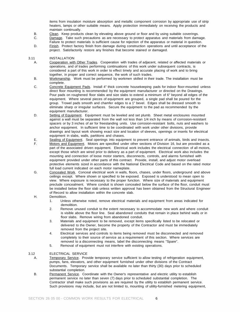
SECTION 26 05 00 - COMMON WORK RESULTS FOR ELECTRICAL 6
items from insulation moisture absorption and metallic component corrosion by appropriate use of strip heaters, lamps or other suitable means. Apply protection immediately on receiving the products and maintain continually.
B. Clean. Keep products clean by elevating above ground or floor and by using suitable coverings. C. Damage. Take such precautions as are necessary to protect apparatus and materials from damage.
Failure to protect materials is sufficient cause for rejection of the apparatus or material in question. D. Finish. Protect factory finish from damage during construction operations and until acceptance of the
project. Satisfactorily restore any finishes that become stained or damaged.
3.11 INSTALLATION A. Cooperation with Other Trades. Cooperation with trades of adjacent, related or affected materials or
operations, and of trades performing continuations of this work under subsequent contracts, is considered a part of this work in order to effect timely and accurate placing of work and to bring together, in proper and correct sequence, the work of such trades.
B. Workmanship. Work must be performed by workmen skilled in their trade. The installation must be complete.
C. Concrete Equipment Pads. Install 4" thick concrete housekeeping pads for indoor floor-mounted unless direct floor mounting is recommended by the equipment manufacturer or directed on the Drawings. Pour pads on roughened floor slabs and size slabs to extend a minimum of 6" beyond all edges of the equipment. Where several pieces of equipment are grouped, a single pad shall be poured for the group. Trowel pads smooth and chamfer edges to a 1" bevel. Edges shall be dressed smooth to eliminate sharp or irregular surfaces. Secure the equipment to the pad as recommended by the equipment manufacturer.
D. Setting of Equipment. Equipment must be leveled and set plumb. Sheet metal enclosures mounted against a wall must be separated from the wall not less than 1/4 inch by means of corrosion-resistant spacers or by 3 inches of air for freestanding units. Use corrosion-resistant bolts, nuts and washers to anchor equipment. In sufficient time to be coordinated with work under other divisions, provide drawings and layout work showing exact size and location of sleeves, openings or inserts for electrical equipment in slabs, walls, partitions and chases.
E. Sealing of Equipment. Seal openings into equipment to prevent entrance of animals, birds and insects. F. Motors and Equipment. Motors are specified under other sections of Division 16, but are provided as a
part of the associated driven equipment. Electrical work includes the electrical connection of all motors, except those which are wired prior to delivery as a part of equipment. Electrical work also includes the mounting and connection of loose motor starters, disconnects, controls, and alarms furnished with equipment provided under other parts of this contract. Provide, install, and adjust motor overload protective elements sized in accordance with the National Electrical Code and based on the rated motor full load current indicated on each motor nameplate.
G. Concealed Work. Conceal electrical work in walls, floors, chases, under floors, underground and above ceilings except. Where shown or specified to be exposed. Exposed is understood to mean open to view. Where exposure is necessary to the proper function. Where size of materials and equipment preclude concealment. Where conduit is shown concealed below the surface of the floor, conduit must be installed below the floor slab unless written approval has been obtained from the Structural Engineer of Record to allow installation within the concrete slab.
H. Demolition. 1. Unless otherwise noted, remove electrical materials and equipment from areas indicated for
demolition. 2. Remove unused conduit to the extent necessary to accommodate new work and where conduit
is visible above the floor line. Seal abandoned conduits that remain in place behind walls or in floor slabs. Remove wiring from abandoned conduit.
3. Materials and equipment to be removed, except items specifically listed to be relocated or delivered to the Owner, become the property of the Contractor and must be immediately removed from the project site.
4. Electrical services and controls to items being removed must be disconnected and removed completely to their source of service as a requirement of this section. Where services are removed to a disconnecting means, label the disconnecting means "Spare".
5. Removal of equipment must not interfere with existing operations.
3.12 ELECTRICAL SERVICE A. Temporary Service. Provide temporary service sufficient to allow testing of refrigeration equipment,
pumps, fans, elevators, and other equipment furnished under other divisions of the Contract Documents. Temporary service shall be available no later than thirty (30) days prior to scheduled substantial completion.
B. Permanent Service. Coordinate with the Owner's representative and electric utility to establish permanent service no later than seven (7) days prior to scheduled substantial completion. The Contractor shall make such provisions as are required by the utility to establish permanent service. Such provisions may include, but are not limited to, mounting of utility-furnished metering equipment,

SECTION 26 05 00 - COMMON WORK RESULTS FOR ELECTRICAL 7
construction of transformer or switchgear pads or vaults in accordance with utility requirements, installation of grounding, or provision of raceways. Delays in obtaining permanent electrical service caused by the Contractor's failure to identify and comply with utility service criteria shall not be cause for increased costs to the Owner nor extension of the Contractor's contractual duration.
C. Outages. Schedule power outages to avoid interference with the Owner's activities. Obtain approval from Owner at least thirty (30) days prior to the requested outage. If required by Owner, provide a schedule showing sequence and duration of all activities during the requested outage.
3.13 TELEPHONE SERVICE
A. Permanent Service. Coordinate with the Owner's representative and telephone utility to establish permanent service no later than seven (7) days prior to scheduled substantial completion. The Contractor shall make such provisions as are required by the utility to establish permanent service. Such provisions may include, but are not limited to, mounting of utility-furnished equipment, installation of grounding, or provision of raceways. Delays in obtaining permanent telephone service caused by the Contractor's failure to identify and comply with utility service criteria shall not be cause for increased costs to the Owner nor extension of the Contractor's contractual duration.
3.14 CABLE TELEVISION SERVICE
A. Permanent Service. Coordinate with the Owner's representative and cable television utility to provide conduit from the point of service to each unit. Make such provisions as are required by the utility to establish this connection. Delays in obtaining the conduit run caused by the Contractor's failure to identify and comply with utility service criteria shall not be cause for increased costs to the Owner nor extension of the Contractor's contractual duration.
3.15 TESTING
A. Test Conditions. Place circuits and equipment into service under normal conditions, collectively and separately, as may be necessary to determine satisfactory operation. Perform specified tests in the presence of the Owner's representative. Furnish all instruments, wiring, equipment and personnel required for conducting tests. Demonstrate that the equipment operates in accordance with requirements of the drawings and specifications. Special tests on certain items are specified hereinafter. Where specified that the testing be performed by an independent testing company, an Owner approved NETA certified testing company shall be used.
B. Test Dates. Schedule final acceptance tests sufficiently in advance of the contract date to permit completion of any necessary adjustment or alterations within the number of days allotted for completion of the contract.
C. Retests. Conduct retests as directed by the Owner's representative of such time duration as may be necessary to assure proper functioning of adjusted or altered parts or items of equipment. Resultant delays as a result of such necessary retests do not relieve the Contractor of his responsibility under this contract.
END OF SECTION 260500
SECTION 26 05 13 - WIRE AND CABLE PART 1 GENERAL
1.01 SECTION INCLUDES
A. Wire
1.02 SYSTEM
A. Furnish wire and cable for all systems except where supplied as part of a system or piece of equipment, where stated otherwise in the specifications or drawings.
1.03 SUBMITTALS
A. Submit this listing as a part of the submittal requirement specified in Section 26 05 00.
PART 2 PRODUCTS
2.01 600V POWER AND GENERAL PURPOSE WIRE
A. Products shall meet NEC 310, UL 83, and the ANSI C8 Series.
B. Conductor shall be copper.
C. NEC Type shall be THWN/THHN.
D. The minimum wire size wire shall be as follows unless otherwise stated on the drawings: 480 V #10; 120/240/240V #12; control #14, stranded; grounding/bonding #12.
PART 3 EXECUTION
3.01 INSTALLATION
A. Install all wiring in conduit, unless stated otherwise on the drawings.
B. Bending radii shall not be less than permitted by ICEA or as recommended by the cable manufacturer,
whichever is greater.
C. Splicing is permissible in boxes, enclosures, handholes, or similar accessible devices. Provide boxes, enclosures, etc. as necessary for the construction of the system even if not detailed on drawings. No splicing in conduit bodies allowed.
D. Ground instrumentation cable shields at the PLC Cabinet.
END OF SECTION 26 05 13
SECTION 26 05 13 - WIRE AND CABLE 1
SECTION 26 10 00 - WIRING METHODS 1
SECTION 26 10 00 - WIRING METHODS PART 1 GENERAL
1.01 SECTION REQUIREMENTS
A. Summary: Building wires and cables and associated splices, connectors, and terminations for wiring systems rated 600 V and less, and twisted-pair cable; and raceways and boxes. Furnish wire and cable for all systems except where supplies as part of the equipment or where specified elsewhere.
PART 2 PRODUCTS
2.01 WIRES AND CABLES
A. Building Wires and Cables: Type XHWN/THWN copper conductor. B. Connectors and Splices: Wiring connectors of size, ampacity rating, material, and type and class for
application and for service indicated. C. Single Conductor Plenum Coaxial: 75-ohm characteristic impedance, solid bare copper central
conductor, foamed Teflon dielectric, 100 percent coverage tinned-copper, double-braid shield, Teflon jacket, suitable for installation in air-handling spaces.
D. Twisted Pair: No. 22 AWG tinned-copper conductors; PVC insulation; overall aluminum/polyester shield and No. 22 AWG tinned-copper drain wire; PVC jacket.
E. Twisted-Pair Plenum: No. 24 AWG, 7-strand, tinned-copper conductors; Teflon insulation; overall aluminum/polyester shield and No. 22 AWG tinned-copper drain wire; Teflon jacket; suitable for use in air-handling spaces.
2.02 RACEWAYS
A. Conduit: Comply with the following: 1. Rigid Steel Conduit: ANSI C80.1. 2. Intermediate Metal Conduit: ANSI C80.6. 3. Electrical metallic Tubing: ANSI C80.3. 4. Rigid Nonmetallic Conduit: NEMA TC 2, Schedule 40.
B. Wireways: Hinged type, with manufacturers standard finish. C. Surface Metal Raceway: Galvanized steel with snap-on covers. Finish with manufacturer's standard
prime coating suitable for painting. D. Surface Nonmetallic Raceway: 2-piece construction, manufactured of rigid PVC compound with matte
texture and manufacturer's standard color. E. Outlet and Device Boxes: UL listed and labeled. F. Floor Boxes: Cast metal, fully adjustable, rectangular, size as shown on the drawings or as necessary
for the installation intended. G. Pull and Junction Boxes, UL listed and labeled.
2.03 ENCLOSURES/BOXES
A. Hinged-Cover Enclosures: NEMA 250, steel enclosure with continuous hinge cover and flush latch. Finish inside and out with manufacturer's standard enamel.
B. Cabinets: NEMA 250, Type 1, except where another Type is indicated. C. Boxes located outdoors shall be NEMA 3R, galvanized steel, or polyester powder finish inside and out
over phosphatized surfaces similar to Hoffman Bulletin A90 Screw Cover Type 3R or approved equal. D. Boxes located indoors shall be NEMA 1, painted or galvanized steel with flat removable cover with
screw similar to Hoffman Bulletin A90 Screw Cover Pull Boxes or approved equal. PART 3 EXECUTION
3.01 INSTALLATION
A. Install wires and cables according to the NECA's "Standard of Installation." B. Remove existing wire from raceway before pulling in new wire and cable. C. Wiring at Outlets: Install with at least 12 inches of slack conductor at each outlet. D. Outdoors Wiring Methods: As follows:
1. Exposed: Rigid or intermediate metal conduit. 2. Concealed: Rigid or intermediate metal conduit. 3. Underground, Single Run: Rigid nonmetallic conduit. 4. Underground, Grouped: Rigid nonmetallic conduit.

SECTION 26 10 00 - WIRING METHODS 2
E. Connection to Vibrating Equipment (Including Transformers and Hydraulic, Pneumatic, Electric Solenoid
or Motor-Driven Equipment): Liquidtight flexible metal conduit. F. Indoors Wiring Methods: As follows: Connection to Vibrating Equipment: Liquidtight flexible metal
conduit. G. Pneumatic, Electric Solenoid or Motor-Driven Equipment: Flexible metal conduit, except in wet or damp
locations use liquidtight flexible metal conduit. Use armored cable and nonmetallic sheathed cable in applications allowed by NEC.
3.02 Raceway Installation.
A. Install raceways, boxes, enclosures, and cabinets as indicated, according to manufacturer's written instructions.
B. Conceal conduit and electrical metallic tubing, unless otherwise indicated, within finished walls, ceilings, and floors.
C. Use raceway fittings compatible with raceway and suitable for use and location. For intermediate steel conduit, use threaded rigid steel conduit fittings, unless otherwise indicated.
D. Raceways Embedded in Slabs: Install in middle third of the slab thickness where practical, and leave at least 1-inch (25-mm) concrete cover.
E. Install exposed raceways parallel to or at right angles to nearby surfaces or structural members, and follow the surface contours as much as practical.
F. Join raceways with fittings designed and approved for the purpose and make joints tight. Use bonding bushings or wedges at connections subject to vibration. Use bonding jumpers where joints cannot be made tight. Use insulating bushings to protect conductors.
G. Install pull wires in empty raceways. Use No. 14 AWG zinc-coated steel or monofilament plastic line having not less than 200-lb (90-kg) tensile strength. Leave not less than 12 inches (300 mm) of slack at each end of the pull wire.
H. Install raceway sealing fittings and locate at suitable, approved, accessible locations and fill them with UL-listed sealing compound. For concealed raceways, install each fitting in a flush steel box with a blank cover plate having a finish similar to that of adjacent plates or surfaces. Install raceway sealing fittings where required by the NEC.
I. Stub-up Connections: Extend conductors to equipment with rigid steel conduit; flexible metal conduit may be used 6 inches (150 mm) above the floor.
J. Flexible Connections: Use maximum of 72 inches (1800 mm) of flexible conduit for recessed and semi- recessed lighting fixtures; for equipment subject to vibration, noise transmission, or movement; and for all motors. Use liquidtight flexible conduit in wet or damp locations. Install separate ground conductor across flexible connections.
K. Install a separate green ground conductor in surface metal raceway from the junction box supplying the raceway to receptacle or fixture ground terminals.
END OF SECTION 26 10 00
SECTION 26 11 10 – CONDUIT 1
SECTION 26 11 10 - CONDUIT
PART 1 GENERAL
1.01 CONDUIT A. Conduit B. Connections C. Adapters D. Fittings E. Clamps F. Hangers
1.02 SUBMITTALS
A. Submit manufacturer’s standard literature for PVC, RMC, EMT.
PART 2 PRODUCTS
2.01 INTERMEDIATE METAL CONDUIT (IMC) A. Must meet NEC 345, and UL 1242.
2.02 RIGID METAL CONDUIT (RMC)
A. Steel RMC shall meet NEC 346, UL 6, and ANSI C80.1. Electrogalvanized on outside, inside, and on threads.
B. Aluminum RMC shall meet NEC 346, UL 6, and ANSI C80.5.
2.03 RIGID NONMETALLIC CONDUIT (RNMC)
A. Rigid nonmetallic conduit shall meet NEC 347, UL 651, and NEMA TC2 for EPC-40. B. Shall be UL listed for use with 90 degrees C. conductors. C. Shall be ultraviolet resistant. Schedule 40 polyvinyl chloride except schedule 80 when called out on the
drawings, schedules. D. All joints shall be glued except where there is a requirement for bell and spigot expansion joints with O
rings. Provide glue to threaded fittings for transitions to thread conduit systems. Fittings and cement shall be per manufacturer’s recommendations.
E. Product shall be Carlon Plus 40, Plus 80 or approved equal.
2.04 ELECTRICAL METALLIC TUBING (EMT) A. Shall meet NEC 348 and UL 797.
2.05 FLEXIBLE METAL TUBING (FMT)
A. Shall meet NEC 349.
2.06 FLEXIBLE METAL CONDUIT A. Shall meet the requirements of NEC 350 and UL 1, and can be aluminum or steel.
2.07 LIQUIDTIGHT FLEXIBLE METALLIC CONDUIT (LFMC)
A. Must conform to NEC 351 (A) and UL 360. B. Shall have a sunlight resistant PVC jacket. C. Must be approved for use in temperatures form –10 degrees C. to + 60 degrees C
2.08 OTHER CONDUITS
A. All other conduits shall meet the requirements of appropriate NEC article and applicable UL standard and shall be used only after approval of Architect.
2.09 COUPLINGS
A. EMT couplings shall be steel, concrete-tight and rain-tight compression type. Set screw or indenter type not acceptable.
B. FMT, FMC, LFMC, LFNC, and XPFC not acceptable. C. Other conduits as required by NEC or as recommended by manufacturer.
2.10 CONNECTORS
A. EMT shall be shall be steel, concrete-tight and rain-tight compression type. Set screw or indenter type not acceptable.

SECTION 26 11 10 – CONDUIT 2
B. FMT, FMC shall be steel squeeze type. Appleton catalog number 7480 through 7490 or approved equal.
C. LFMC shall be Appleton ASTM series or approved equal. D. Other conduit as recommended by manufacturer.
PART 3 EXECUTION
3.01 DRAWINGS
A. The conduit runs are not detailed on the drawings. Install as implied by the panel schedules, one-line diagrams, and as required for the complete system.
3.02 INSTALLATION
A. For conduit bends in all but EMT and in IMC less than 1 inch shall be factory made or made with a conduit bending machine recommended by conduit manufacturer. Handmade bends are not acceptable.
B. Make bends in EMT or in 1 inch ¾ inch IMC with a hand ender, which fully supports the side wall. C. Wrench tighten all threaded joints, couplings, and connectors. D. Wrench tighten all fittings. E. Run conduit concealed in finish areas and where indicated on the drawings. In many places, such as at
motor and surface-mounted wiring devices in pump rooms and electrical rooms, the end of a run may be an exposed vertical riser even though the symbol used for the conduit denotes concealed.
F. Run exposed either parallel with or perpendicular to structural members of the building or structural except where allowed to otherwise by the engineer.
G. The only conduit that maybe run on the roof is conduit that serves equipment on that roof. Locate roof penetrations so no horizontal run of conduit are required on the roof.
H. Conduit installed above lay-in ceiling will be considered to be concealed, and need not comply with requirements for exposed conduit. Route to avoid interference with piping, ductwork, and luminaries. Locate conduit well above the lay-in ceiling.
I. Do not install conduit on slabs, decks, sidewalks or floors where it may create a trip hazard. The Engineer or Owner are judges on what conditions are a “trip hazard”. Conduits may be installed on slabs only with written permission from the Engineer or Owner.
J. Expansion joints: where conduit spans building expansion joints or in long duct runs, use expansion fittings and bonding jumpers.
K. Drainage: avoid pockets in conduit runs. Provide suitable drainage fittings in low spots in exposed conduit. Weep holes not permitted.
L. Field cuts and threads: 1. Cut ends of conduit square with hand or power saw and ream to remove burrs and sharp edges. Do
not use wheel cutter. 2. Threads cut on job shall have same effective length, thread dimensions, and taper as factory cut
threads. 3. Carefully remove burrs from threads and paint conduit threads with 1 coat of zinc rich spray primer.
Rust-Oleum Model 2185 or similar. M. Supports:
1. Hangers, supports, or fastenings: provide at each elbow and at end of every straight run terminating in box or cabinet. Rigid fastenings spaced maximum of 7 foot horizontal, 8 feet vertical; adjustable supports spaced maximum of 7 feet.
2. Clamps: comply with manufactures’ recommendations. 3. One-hole straps are to be installed with hole below conduit in horizontal runs. 4. Trapeze hangers:
a. Use to support horizontal runs only. b. Install U-bolts at end of each run and at each elbow. Install clamps every third intermediate hanger
for each conduit. Hangers are not detailed but must be adequate to support combined weight of conduit, conductors, and hangers.
c. Material: aluminum unistrut with stainless steel fittings, or Robroy Rob- Glass fiberglass strut support system.
N. Conduit ends: 1. Cap spare conduit. 2. Open conduit ends terminating in trenches, panels or enclosures: plug space around cable with
commercial duct-sealing compound. 3. Cap conduit ends during construction to prevent entrance of foreign material. 4. Install grounding bushing or conduit terminations. Bond grounding bushing to ground conductor
included in conduit run.
O. Cleaning: Clean and swab inside by mechanical means to remove foreign materials and moisture before wires or cables are installed.
3.03 APPLICATION
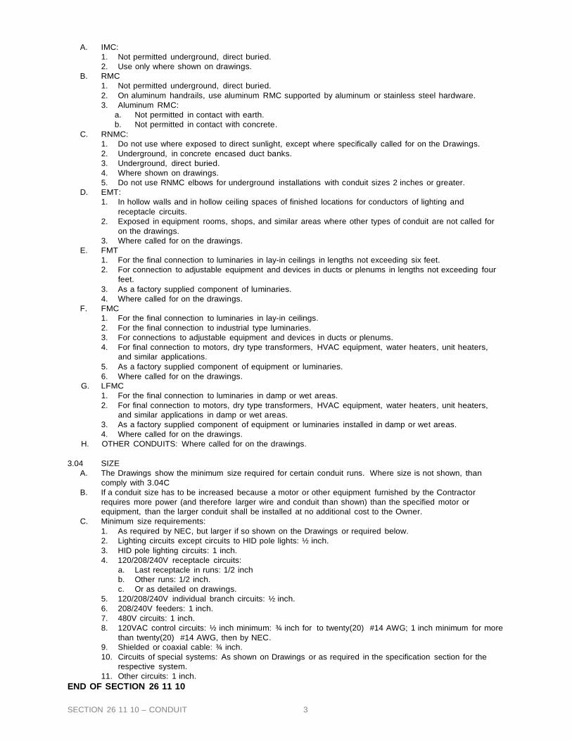
SECTION 26 11 10 – CONDUIT 3
A. IMC: 1. Not permitted underground, direct buried. 2. Use only where shown on drawings.
B. RMC 1. Not permitted underground, direct buried. 2. On aluminum handrails, use aluminum RMC supported by aluminum or stainless steel hardware. 3. Aluminum RMC:
a. Not permitted in contact with earth. b. Not permitted in contact with concrete.
C. RNMC: 1. Do not use where exposed to direct sunlight, except where specifically called for on the Drawings. 2. Underground, in concrete encased duct banks. 3. Underground, direct buried. 4. Where shown on drawings. 5. Do not use RNMC elbows for underground installations with conduit sizes 2 inches or greater.
D. EMT: 1. In hollow walls and in hollow ceiling spaces of finished locations for conductors of lighting and
receptacle circuits. 2. Exposed in equipment rooms, shops, and similar areas where other types of conduit are not called for
on the drawings. 3. Where called for on the drawings.
E. FMT 1. For the final connection to luminaries in lay-in ceilings in lengths not exceeding six feet. 2. For connection to adjustable equipment and devices in ducts or plenums in lengths not exceeding four
feet. 3. As a factory supplied component of luminaries. 4. Where called for on the drawings.
F. FMC 1. For the final connection to luminaries in lay-in ceilings. 2. For the final connection to industrial type luminaries. 3. For connections to adjustable equipment and devices in ducts or plenums. 4. For final connection to motors, dry type transformers, HVAC equipment, water heaters, unit heaters,
and similar applications. 5. As a factory supplied component of equipment or luminaries. 6. Where called for on the drawings.
G. LFMC 1. For the final connection to luminaries in damp or wet areas. 2. For final connection to motors, dry type transformers, HVAC equipment, water heaters, unit heaters,
and similar applications in damp or wet areas. 3. As a factory supplied component of equipment or luminaries installed in damp or wet areas. 4. Where called for on the drawings.
H. OTHER CONDUITS: Where called for on the drawings.
3.04 SIZE A. The Drawings show the minimum size required for certain conduit runs. Where size is not shown, than
comply with 3.04C B. If a conduit size has to be increased because a motor or other equipment furnished by the Contractor
requires more power (and therefore larger wire and conduit than shown) than the specified motor or equipment, than the larger conduit shall be installed at no additional cost to the Owner.
C. Minimum size requirements: 1. As required by NEC, but larger if so shown on the Drawings or required below. 2. Lighting circuits except circuits to HID pole lights: ½ inch. 3. HID pole lighting circuits: 1 inch. 4. 120/208/240V receptacle circuits:
a. Last receptacle in runs: 1/2 inch b. Other runs: 1/2 inch. c. Or as detailed on drawings.
5. 120/208/240V individual branch circuits: ½ inch. 6. 208/240V feeders: 1 inch. 7. 480V circuits: 1 inch. 8. 120VAC control circuits: ½ inch minimum: ¾ inch for to twenty(20) #14 AWG; 1 inch minimum for more
than twenty(20) #14 AWG, then by NEC. 9. Shielded or coaxial cable: ¾ inch. 10. Circuits of special systems: As shown on Drawings or as required in the specification section for the
respective system. 11. Other circuits: 1 inch.
END OF SECTION 26 11 10

SECTION 26 21 00 – ELECTRICAL SERVICE PART 1 GENERAL
1.01 SYTEM DESCRIPTION
A. Coordinate upgrade or new service with local utility company.
B. Include in the BID cost associated with service upgrade or securing new service.
C. Pay all monthly electrical charges while the facility is under construction. Coordinate
electrical charges with the Owner.
D. Arrange with local utility and provide any necessary poles, meters, etc., for PERMANENT power.
1.02 TEMPORARY POWER
A. If any additional temporary electrical power is needed the Contractor shall provide at this own
expense.
B. Arrange with local utility and provide any necessary poles, meters, etc., for temporary power.
C. After the completion of construction remove any temporary power facilities.
PART 2 PRODUCTS (NOT USED)
PART 3 EXECUTION (NOT USED)
END OF SECTION 26 21 00
SECTION 26 21 00 – ELECTRICAL SERVICE -1
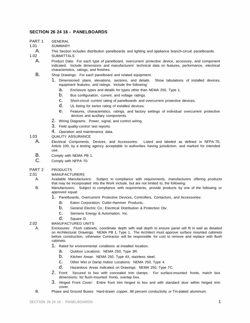
1 SECTION 26 24 16 - PANELBOARDS
SECTION 26 24 16 - PANELBOARDS PART 1 GENERAL 1.01 SUMMARY
A. This Section includes distribution panelboards and lighting and appliance branch-circuit panelboards. 1.02 SUBMITTALS
A. Product Data: For each type of panelboard, overcurrent protective device, accessory, and component indicated. Include dimensions and manufacturers' technical data on features, performance, electrical characteristics, ratings, and finishes.
B. Shop Drawings: For each panelboard and related equipment. 1. Dimensioned plans, elevations, sections, and details. Show tabulations of installed devices,
equipment features, and ratings. Include the following: a. Enclosure types and details for types other than NEMA 250, Type 1. b. Bus configuration, current, and voltage ratings. c. Short-circuit current rating of panelboards and overcurrent protective devices. d. UL listing for series rating of installed devices. e. Features, characteristics, ratings, and factory settings of individual overcurrent protective
devices and auxiliary components. 2. Wiring Diagrams: Power, signal, and control wiring. 3. Field quality-control test reports. 4. Operation and maintenance data.
1.03 QUALITY ASSURANCE A. Electrical Components, Devices, and Accessories: Listed and labeled as defined in NFPA 70,
Article 100, by a testing agency acceptable to authorities having jurisdiction, and marked for intended use.
B. Comply with NEMA PB 1. C. Comply with NFPA 70.
PART 2 PRODUCTS 2.01 MANUFACTURERS
A. Available Manufacturers: Subject to compliance with requirements, manufacturers offering products that may be incorporated into the Work include, but are not limited to, the following:
B. Manufacturers: Subject to compliance with requirements, provide products by one of the following or approved equal: 1. Panelboards, Overcurrent Protective Devices, Controllers, Contactors, and Accessories:
a. Eaton Corporation; Cutler-Hammer Products. b. General Electric Co.; Electrical Distribution & Protection Div. c. Siemens Energy & Automation, Inc. d. Square D.
2.02 MANUFACTURED UNITS A. Enclosures: Flush cabinets, coordinate depth with wall depth to ensure panel will fit in wall as detailed
on Architectural Drawings. NEMA PB 1, Type 1. The Architect must approve surface mounted cabinets before construction, otherwise Contractor will be responsible for cost to remove and replace with flush cabinets. 1. Rated for environmental conditions at installed location.
a. Outdoor Locations: NEMA 250, Type 3R. b. Kitchen Areas: NEMA 250, Type 4X, stainless steel. c. Other Wet or Damp Indoor Locations: NEMA 250, Type 4. d. Hazardous Areas Indicated on Drawings: NEMA 250, Type 7C.
2. Front: Secured to box with concealed trim clamps. For surface-mounted fronts, match box dimensions; for flush-mounted fronts, overlap box.
3. Hinged Front Cover: Entire front trim hinged to box and with standard door within hinged trim cover.
B. Phase and Ground Buses: Hard-drawn copper, 98 percent conductivity or Tin-plated aluminum.
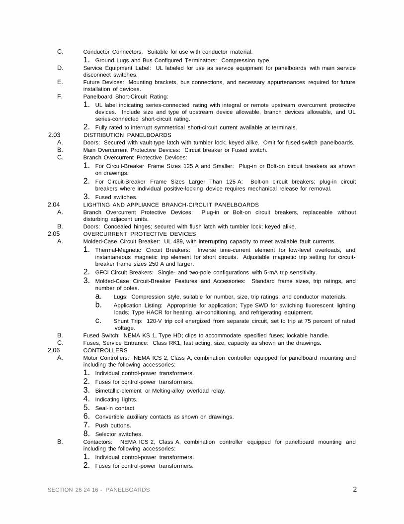
2 SECTION 26 24 16 - PANELBOARDS
C. Conductor Connectors: Suitable for use with conductor material. 1. Ground Lugs and Bus Configured Terminators: Compression type.
D. Service Equipment Label: UL labeled for use as service equipment for panelboards with main service disconnect switches.
E. Future Devices: Mounting brackets, bus connections, and necessary appurtenances required for future installation of devices.
F. Panelboard Short-Circuit Rating: 1. UL label indicating series-connected rating with integral or remote upstream overcurrent protective
devices. Include size and type of upstream device allowable, branch devices allowable, and UL series-connected short-circuit rating.
2. Fully rated to interrupt symmetrical short-circuit current available at terminals. 2.03 DISTRIBUTION PANELBOARDS
A. Doors: Secured with vault-type latch with tumbler lock; keyed alike. Omit for fused-switch panelboards. B. Main Overcurrent Protective Devices: Circuit breaker or Fused switch. C. Branch Overcurrent Protective Devices:
1. For Circuit-Breaker Frame Sizes 125 A and Smaller: Plug-in or Bolt-on circuit breakers as shown on drawings.
2. For Circuit-Breaker Frame Sizes Larger Than 125 A: Bolt-on circuit breakers; plug-in circuit breakers where individual positive-locking device requires mechanical release for removal.
3. Fused switches. 2.04 LIGHTING AND APPLIANCE BRANCH-CIRCUIT PANELBOARDS
A. Branch Overcurrent Protective Devices: Plug-in or Bolt-on circuit breakers, replaceable without disturbing adjacent units.
B. Doors: Concealed hinges; secured with flush latch with tumbler lock; keyed alike. 2.05 OVERCURRENT PROTECTIVE DEVICES
A. Molded-Case Circuit Breaker: UL 489, with interrupting capacity to meet available fault currents. 1. Thermal-Magnetic Circuit Breakers: Inverse time-current element for low-level overloads, and
instantaneous magnetic trip element for short circuits. Adjustable magnetic trip setting for circuit- breaker frame sizes 250 A and larger.
2. GFCI Circuit Breakers: Single- and two-pole configurations with 5-mA trip sensitivity. 3. Molded-Case Circuit-Breaker Features and Accessories: Standard frame sizes, trip ratings, and
number of poles. a. Lugs: Compression style, suitable for number, size, trip ratings, and conductor materials. b. Application Listing: Appropriate for application; Type SWD for switching fluorescent lighting
loads; Type HACR for heating, air-conditioning, and refrigerating equipment. c. Shunt Trip: 120-V trip coil energized from separate circuit, set to trip at 75 percent of rated
voltage. B. Fused Switch: NEMA KS 1, Type HD; clips to accommodate specified fuses; lockable handle. C. Fuses, Service Entrance: Class RK1, fast acting, size, capacity as shown an the drawings.
2.06 CONTROLLERS A. Motor Controllers: NEMA ICS 2, Class A, combination controller equipped for panelboard mounting and
including the following accessories: 1. Individual control-power transformers. 2. Fuses for control-power transformers. 3. Bimetallic-element or Melting-alloy overload relay. 4. Indicating lights. 5. Seal-in contact. 6. Convertible auxiliary contacts as shown on drawings. 7. Push buttons. 8. Selector switches.
B. Contactors: NEMA ICS 2, Class A, combination controller equipped for panelboard mounting and including the following accessories: 1. Individual control-power transformers. 2. Fuses for control-power transformers.

3 SECTION 26 24 16 - PANELBOARDS
3. Indicating lights. 4. Seal-in contact. 5. Convertible auxiliary contacts s shown on drawings. 6. Push buttons. 7. Selector switches.
C. Controller Disconnect Switches: Fused switch or Adjustable instantaneous-trip circuit breaker interlocked with controller. 1. Auxiliary Contacts: Integral with disconnect switches to de-energize external control-power source.
D. Contactors in Main Bus: NEMA ICS 2, Class A, mechanically held general-purpose controller. 1. Control-Power Source: Control-power transformer, with fused primary and secondary terminals,
connected to main bus ahead of contactor connection. 2. Control-Power Source: 120-V branch circuit.
PART 3 EXECUTION 3.01 INSTALLATION
A. Install panelboards and accessories according to NEMA PB 1.1. B. Comply with mounting and anchoring requirements specified by the Manufacturer." C. Mount top of trim 74 inches above finished floor, unless otherwise indicated. D. Mount plumb and rigid without distortion of box. Mount recessed panelboards with fronts uniformly flush
with wall finish. Coordinate depth with wall thickness as shown on Architectural drawings. E. Install overcurrent protective devices and controllers.
1. Set field-adjustable switches and circuit-breaker trip ranges. F. Install filler plates in unused spaces. G. Stub four 1-inch (27-GRC) empty conduits from panelboard into accessible ceiling space or space
designated to be ceiling space in the future. Stub four 1-inch (27-GRC) empty conduits into raised floor space or below slab not on grade.
H. Identify field-installed conductors, interconnecting wiring, and components; provide warning signs as specified in Division 16 Section "Basic Electrical Materials and Methods."
I. Panelboard Nameplates: Label each panelboard with engraved metal or laminated-plastic nameplate mounted with corrosion-resistant screws.
J. Ground equipment according to drawings and NEC. K. Connect wiring according to Division 26 10 00, “Wiring Methods."
3.02 FIELD QUALITY CONTROL A. Prepare for acceptance tests as follows:
1. Test insulation resistance for each panelboard bus, component, connecting supply, feeder, and control circuit.
2. Test continuity of each circuit.
B. Perform the following field tests and inspections and prepare test reports: 3. Perform each electrical test and visual and mechanical inspection stated in NETA ATS, Section 7.5
for switches and Section 7.6 for molded-case circuit breakers. Certify compliance with test parameters.
1. Correct malfunctioning units on-site, where possible, and retest to demonstrate compliance; otherwise, replace with new units and retest.
END OF SECTION 26 24 16

SECTION 26 27 26 - WIRING DEVICES PART 1 GENERAL
1.01 SECTION REQUIREMENTS
A. Submit Product Data.
PART 2 PRODUCTS
2.01 DEVICES
A. General Purpose Wiring Devices: Comply with NEMA WD1. Color: As per Architect selection.
B. Receptacles: UL 498, heavy-duty grade except as indicated otherwise or NEMA 5-20R, back and side
wiring feature, positive clamping with screw activated pressure plate. Hubbell CR5262 series, Leviton BR15 series or approved equal.
C. Ground-Fault Circuit Interrupter Receptacles: UL 943, feed-through type, with integral NEMA 5-20R
duplex receptacle; for installation in a 2-3/4-inch- deep outlet box without an adapter. Side wired, flush polycarbonate face, trip level 4 to 6 mA, trip time .025 seconds nominal, Hubbell GF5252A, Leviton 6599 series or approved equal.
D. Snap Switches: Quiet-type ac switches, 120/277 V, 20 A, complying with UL 20. Back and side wiring
positive clamping with screw activated pressure plate, motor switching rated 1 ½ horsepower at 120 VAC, 2 horsepower at 240 VAC. Hubbell HBl 1221, HBL 1222, HBL 1223, HBL 1224 series, Leviton 1221-2, 1222-2, 1223-2, 1224-2 series or approved equal.
E. Incandescent Lamp Dimmers: Modular, 120 V, 60 Hz with continuously adjustable slide, single-pole
with soft tap or other quiet switch.
F. Fluorescent Lamp Dimmers: Modular, compatible with dimmer ballasts and capable of consistent dimming to a maximum of 10 percent of full brightness. Include trim potentiometer.
G. Wall Plates, Finished Areas: as per Architectural drawings, fastened with metal screws having heads
matching plate color. Wall plates shall be polycarbonate or nylon, premium grade, Hubbell PJ series or approved equal.
H. Wall Plates, Unfinished Areas: Galvanized steel with metal screws.
1. Floor Service Fittings: Modular, above-floor, dual-service units suitable for wiring method used. 2. Multioutlet Assemblies: Comply with UL 5.
PART 3 EXECUTION
3.01 INSTALLATION
A. Install devices and assemblies plumb and secure and at the correct height to meet ADA requirements. B. Mount devices flush, with long dimension vertical, and grounding terminal of receptacles on top. Group
adjacent switches under single, multigang wall plates. C. Protect devices and assemblies during painting. D. Mount toggle switches at 42 inches above FF, receptacles at 18 inches above FF unless otherwise
shown on the drawings. Receptacles mount U ground down. E. Install wall plates when painting is complete.
END OF SECTION 26 27 26
SECTION 26 27 26 - WIRING DEVICES

SECTION 26 28 16 - ENCLOSED SWITCHES AND CIRCUIT BREAKERS
PART 1 GENERAL (Not Applicable)
PART 2 PRODUCTS
2.01 SWITCHES
A. Enclosed, Nonfusible Switch: NEMA KS 1, Type HD, with lockable handle.
B. Enclosed, Fusible Switch, 800 A and Smaller: NEMA KS 1, Type HD, clips to accommodate specified fuses, enclosure consistent with environment where located, handle lockable with 2 padlocks, and interlocked with cover in closed position.
2.02 CIRCUIT BREAKERS
A. Enclosed, Molded-Case Circuit Breaker: NEMA AB 1, with lockable handle.
B. Characteristics: Frame size, trip rating, number of poles, and auxiliary devices as indicated and
interrupting rating to meet available fault current.
C. Circuit Breakers, 200 A and Larger: Trip units interchangeable within frame size.
D. Circuit Breakers, 400 A and Larger: Field-adjustable, short-time and continuous-current settings.
E. Current-Limiting Trips: Where indicated, let-through ratings less than
NEMA FU 1, Class RK-5.
F. Enclosure: NEMA AB 1, Type 1, unless otherwise specified or required to meet environmental conditions of installed location.
PART 3 EXECUTION
3.01 TESTING
A. Perform visual and mechanical inspections and electrical tests stated in
NETA ATS.
END OF SECTION 26 28 16
SECTION 26 28 16 - ENCLOSED SWITCHES AND CIRCUIT BREAKERS
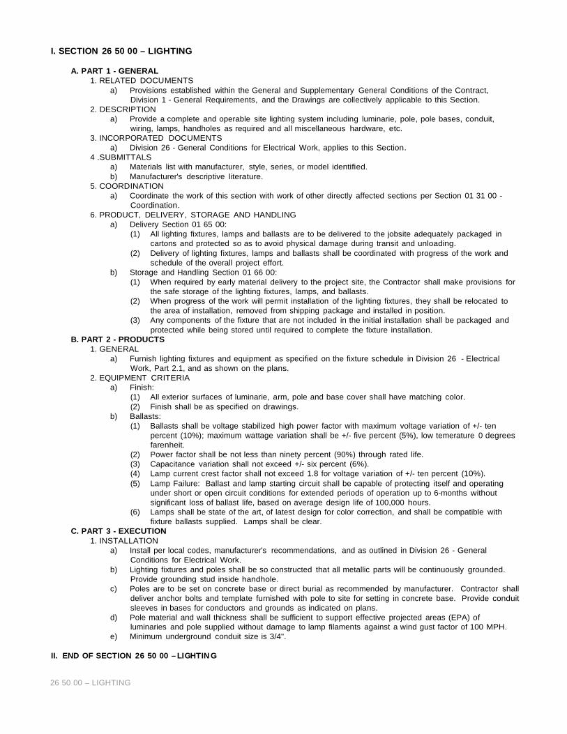
I. SECTION 26 50 00 – LIGHTING
A. PART 1 - GENERAL 1. RELATED DOCUMENTS
a) Provisions established within the General and Supplementary General Conditions of the Contract, Division 1 - General Requirements, and the Drawings are collectively applicable to this Section.
2. DESCRIPTION a) Provide a complete and operable site lighting system including luminarie, pole, pole bases, conduit,
wiring, lamps, handholes as required and all miscellaneous hardware, etc. 3. INCORPORATED DOCUMENTS
a) Division 26 - General Conditions for Electrical Work, applies to this Section. 4 .SUBMITTALS
a) Materials list with manufacturer, style, series, or model identified. b) Manufacturer's descriptive literature.
5. COORDINATION a) Coordinate the work of this section with work of other directly affected sections per Section 01 31 00 -
Coordination. 6. PRODUCT, DELIVERY, STORAGE AND HANDLING
a) Delivery Section 01 65 00: (1) All lighting fixtures, lamps and ballasts are to be delivered to the jobsite adequately packaged in
cartons and protected so as to avoid physical damage during transit and unloading. (2) Delivery of lighting fixtures, lamps and ballasts shall be coordinated with progress of the work and
schedule of the overall project effort. b) Storage and Handling Section 01 66 00:
(1) When required by early material delivery to the project site, the Contractor shall make provisions for the safe storage of the lighting fixtures, lamps, and ballasts.
(2) When progress of the work will permit installation of the lighting fixtures, they shall be relocated to the area of installation, removed from shipping package and installed in position.
(3) Any components of the fixture that are not included in the initial installation shall be packaged and protected while being stored until required to complete the fixture installation.
B. PART 2 - PRODUCTS 1. GENERAL
a) Furnish lighting fixtures and equipment as specified on the fixture schedule in Division 26 - Electrical Work, Part 2.1, and as shown on the plans.
2. EQUIPMENT CRITERIA a) Finish:
(1) All exterior surfaces of luminarie, arm, pole and base cover shall have matching color. (2) Finish shall be as specified on drawings.
b) Ballasts: (1) Ballasts shall be voltage stabilized high power factor with maximum voltage variation of +/- ten
percent (10%); maximum wattage variation shall be +/- five percent (5%), low temerature 0 degrees farenheit.
(2) Power factor shall be not less than ninety percent (90%) through rated life. (3) Capacitance variation shall not exceed +/- six percent (6%). (4) Lamp current crest factor shall not exceed 1.8 for voltage variation of +/- ten percent (10%). (5) Lamp Failure: Ballast and lamp starting circuit shall be capable of protecting itself and operating
under short or open circuit conditions for extended periods of operation up to 6-months without significant loss of ballast life, based on average design life of 100,000 hours.
(6) Lamps shall be state of the art, of latest design for color correction, and shall be compatible with fixture ballasts supplied. Lamps shall be clear.
C. PART 3 - EXECUTION 1. INSTALLATION
a) Install per local codes, manufacturer's recommendations, and as outlined in Division 26 - General Conditions for Electrical Work.
b) Lighting fixtures and poles shall be so constructed that all metallic parts will be continuously grounded. Provide grounding stud inside handhole.
c) Poles are to be set on concrete base or direct burial as recommended by manufacturer. Contractor shall deliver anchor bolts and template furnished with pole to site for setting in concrete base. Provide conduit sleeves in bases for conductors and grounds as indicated on plans.
d) Pole material and wall thickness shall be sufficient to support effective projected areas (EPA) of luminaries and pole supplied without damage to lamp filaments against a wind gust factor of 100 MPH.
e) Minimum underground conduit size is 3/4".
II. END OF SECTION 26 50 00 – LI GHTIN G
26 50 00 – LIGHTING

27 00 00 – COMMUNICATIONS: TELEPHONE, CABLE TV, & SECURITY 1
SECTION 27 00 00 – COMMUNICATIONS: TELEPHONE, CABLE TV, & SECURITY SYSTEMS
A. PART 1 - GENERAL 1. RELATED DOCUMENTS
a) Provisions established within the General and Supplementary General Conditions of the Contract, Division 1 - General Requirements, and the Drawings are collectively applicable to this Section.
2. SECTION INCLUDES a) Telephone System Wiring b) Cable Television System Wiring c) Security System Wiring
3. SUBMITTALS a) General: Submit the following in accordance with section 01 33 00 - Submittals. b) Product Data including all pertinent performance characteristics and criteria. c) Shop Drawings: Indicate materials, construction, locations, sizes, quantities, finishes, and
installation. 4. DELIVERY, STORAGE, AND HANDLING
a) Deliver, store, handle, and protect products in accordance with section 01 65 00 – Delivery Requirements and Section 01 66 00 Storage and Handling Requirements.
5. COORDINATION a) Coordinate the work of this section with work of other directly affected sections per Section 01 31 00
- Coordination.
B. PART 2 - PRODUCTS 1. GENERAL
a) Contractor shall furnish and install all materials, labor, tools and equipment to install, connect and test to provide a complete wiring system for telephone, cable TV, and security systems.
2. TELEPHONE a) Each unit shall have an individual 6 pair cable to the interface junction box. Wiring shall be 6 pair,
24 gauge, category 5 copper cable. b) Wiring from the interface junction box to each outlet shall be 6 pair terminated on a two line duplex
outlet. c) Multiconductor cable to each building shall include (6) pair per unit plus 25 additional pair for other
systems; security, fire alarm, etc. d) A "ring down" test shall be performed on all wiring. All wiring shall be tagged at each terminal block
and at building cabinets and clubhouse terminals. e) Cable splices shall utilize 710 SCI-25 Splice Module connectors. Install 4'x8'x3/4" plywood at closet
and terminate all cables on RJ21 blocks with unit tag numbers. Interface wiring to be by others. 3. CABLE TELEVISION
a) An individual coaxial cable, RG6 quad-shield with 90 percent braid, 750 MHz, shall be installed from the building's terminal box to each structured cable box. Unit wiring to all locations shown on electrical plan.
b) All cables shall be tested after installation to assure compliance with FCC maximum leakage standards. Measurements shall be recorded and submitted for final project documentation.
c) Terminate cables in end cabinets, N3R, 24"x36", with 1MHz splitters. Provide adjacent 120V power for supplemental amplifier by others. Superior Cabinet Model #PEHST.
d) All TV jacks shall be installed in standard single gang boxes with "F" crimp type connectors and Levitron #102-40244-00W outlet and plate.
4. SECURITY SYSTEMS a) Each Commercial and Ground Floor unit shall be pre-wired for security devices and master
keyboard. All ground floor units shall be pre-wired for window detection devices. b) Security System Products
(1) Windows: Recessed Magnetic Contacts (2) Doors: Recessed Roller Plunger Doors (3) Preferred Manufacturer: Sentrol Inc.
C. PART 3 - EXECUTION
1. INSTALLATION a) The wiring systems will be installed from the unit outlets to terminal boxes on the end of the
buildings and then underground to the terminal boxes at the equipment room, except for security. b) If allowed by the local Power Company, TV and telephone wiring may be installed in the same
trench as the power cables. Maintain separation and backfill per Power Company standards. Provide all additional trenching and backfill required to buildings.
c) Provide wiring for all outlets as shown on the electrical drawings. Include miscellaneous wiring for

27 00 00 – COMMUNICATIONS: TELEPHONE, CABLE TV, & SECURITY 2
gate operators, clubhouse and pool. d) All underground wiring shall be installed in conduits, PVC Schedule 40 with long radius elbows, or to
meet the requirements of the serving utility. e) Underground conduits shall be a minimum of 30" below grade with a #6 solid copper ground.
Ground shall be tied to building grounding system and should test less than 3 Ohms. All coax shields shall be grounded.
f) All cables shall be clearly marked after termination. Continuity tests reports shall be logged and turned in for final project documents.
g) Final color coding instruction, mounting heights and locations shall be provided prior to final trim out.
END OF SECTION 27 00 00 – COMMUNICATIONS: TELEPHONE, CABLE TV, & SECURITY
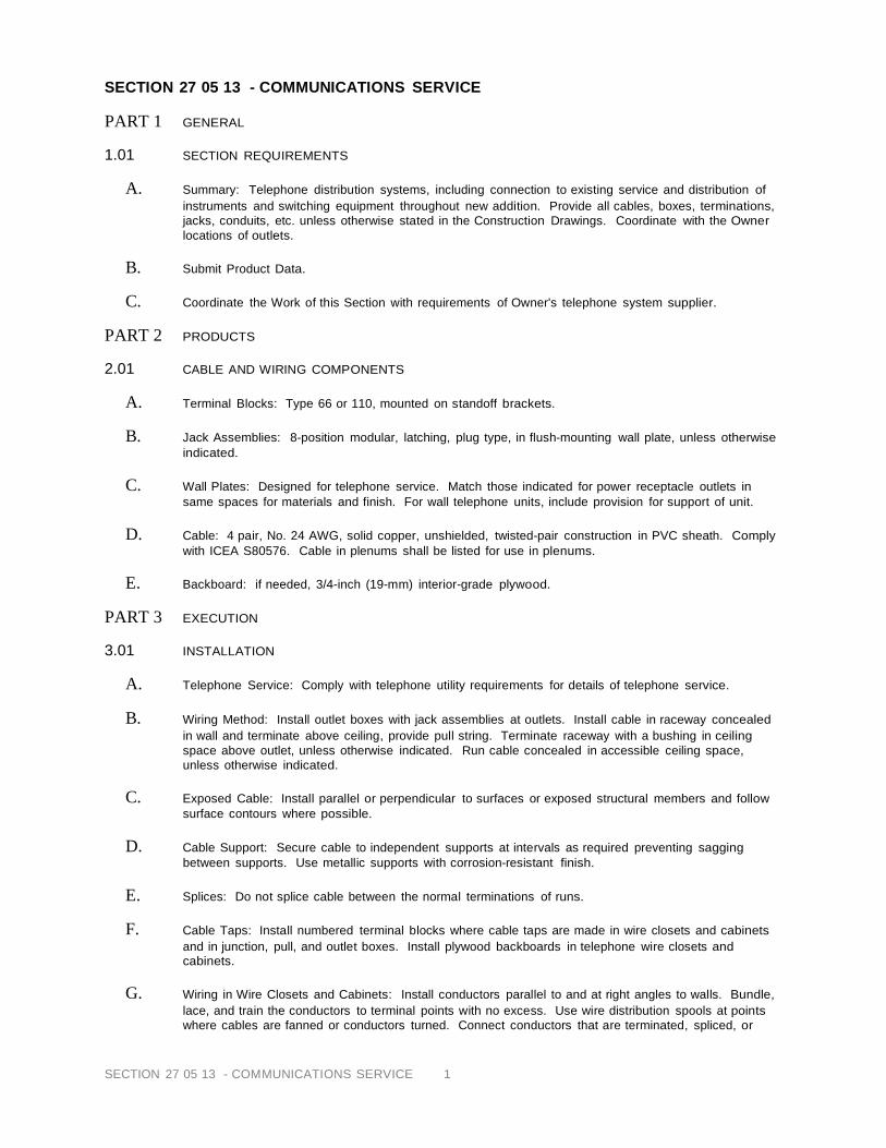
SECTION 27 05 13 - COMMUNICATIONS SERVICE 1
SECTION 27 05 13 - COMMUNICATIONS SERVICE PART 1 GENERAL
1.01 SECTION REQUIREMENTS
A. Summary: Telephone distribution systems, including connection to existing service and distribution of
instruments and switching equipment throughout new addition. Provide all cables, boxes, terminations, jacks, conduits, etc. unless otherwise stated in the Construction Drawings. Coordinate with the Owner locations of outlets.
B. Submit Product Data.
C. Coordinate the Work of this Section with requirements of Owner's telephone system supplier.
PART 2 PRODUCTS
2.01 CABLE AND WIRING COMPONENTS
A. Terminal Blocks: Type 66 or 110, mounted on standoff brackets.
B. Jack Assemblies: 8-position modular, latching, plug type, in flush-mounting wall plate, unless otherwise
indicated.
C. Wall Plates: Designed for telephone service. Match those indicated for power receptacle outlets in same spaces for materials and finish. For wall telephone units, include provision for support of unit.
D. Cable: 4 pair, No. 24 AWG, solid copper, unshielded, twisted-pair construction in PVC sheath. Comply
with ICEA S80576. Cable in plenums shall be listed for use in plenums.
E. Backboard: if needed, 3/4-inch (19-mm) interior-grade plywood. PART 3 EXECUTION
3.01 INSTALLATION
A. Telephone Service: Comply with telephone utility requirements for details of telephone service.
B. Wiring Method: Install outlet boxes with jack assemblies at outlets. Install cable in raceway concealed
in wall and terminate above ceiling, provide pull string. Terminate raceway with a bushing in ceiling space above outlet, unless otherwise indicated. Run cable concealed in accessible ceiling space, unless otherwise indicated.
C. Exposed Cable: Install parallel or perpendicular to surfaces or exposed structural members and follow
surface contours where possible.
D. Cable Support: Secure cable to independent supports at intervals as required preventing sagging between supports. Use metallic supports with corrosion-resistant finish.
E. Splices: Do not splice cable between the normal terminations of runs.
F. Cable Taps: Install numbered terminal blocks where cable taps are made in wire closets and cabinets
and in junction, pull, and outlet boxes. Install plywood backboards in telephone wire closets and cabinets.
G. Wiring in Wire Closets and Cabinets: Install conductors parallel to and at right angles to walls. Bundle,
lace, and train the conductors to terminal points with no excess. Use wire distribution spools at points where cables are fanned or conductors turned. Connect conductors that are terminated, spliced, or

SECTION 27 05 13 - COMMUNICATIONS SERVICE 2
interrupted to terminal blocks. Label each terminal with designations approved by telephone equipment supplier.
H. Conductor Terminations: Terminate conductors of cables on terminal block using tools recommended
by terminal block manufacturer.
I. Identify telephone system backboards and cabinets with the legend "Telephone." Identify terminals of terminal strip and jack outlets and pull-and-junction boxes with approved designations.
3.02 TESTING
A. Acceptance Tests: Test each pair or conductor of each cable run for continuity of pair loop; insulation
resistance for pair loop (report evaluation of readings less than 1 megaohm); and dc loop resistance (report evaluation of differences greater than 3 percent).
END OF 27 05 13 - COMMUNICATIONS SERVICE

28 31 00 - FIRE ALARM SYSTEM/ 1
SECTION 28 31 00 - FIRE ALARM SYSTEM
A. PART 1 - GENERAL 1. RELATED DOCUMENTS
a) Provisions established within the General and Supplementary General Conditions of the Contract, Division 1 - General Requirements, and the Drawings are collectively applicable to this Section.
2. WORK INCLUDED a) Fire alarm system including all required components. b) Furnish and install an integrated analog Fire Alarm System as described herein. The system
includes processing units, local data panels, remote annunciator(s), peripheral alarm devices, and outputs for specified control functions.
3. REGULATORY REQUIREMENTS a) System: UL and FM listed. b) Conform to requirements of NFPA 72 and 101. c) Conform to applicable local codes and directives of authorities having jurisdiction. d) Conform to all handicap accessibility codes in jurisdiction having authority.
4. SUBMITTALS a) General: Submit following items in accordance with Section 01 33 00 - Submittals. b) Product Data: Including all pertinent performance characteristics and criteria. c) Shop Drawings: Indicate materials, construction, sizes, quantities, finishes, installation details. d) Obtain approvals of authorities having jurisdiction and submit approved Shop Drawing to Owner
for records. 5. COORDINATION
a) Coordinate work with work of other directly affected sections per Section 01 31 00. 6. DELIVERY, STORAGE AND HANDLING
a) Deliver, store, handle, and protect products in accordance with Section 01 65 00 - Delivery, & Section 01 66 00 Storage and Handling.
B. PART 2 - PRODUCTS
1. MANUFACTURERS a) Autocall, Simplex, Edwards, FCI, or approved equal.
2. INITIATING DEVICES a) Manual Station: Semi-flush mounted, single action manual station, center break glass cover. b) Spot Heat Detector: Combination rate-of-rise and fixed temperature, rated 135 degrees F and
temperature rate of rise of 15 degrees F. 3. ANNUNCIATION DEVICES
a) Pre-wire for mini annunciator horn in each unit. Provide strobe in all handicap accessible locations. Refer to Drawings for locations.
b) The fire alarm control panel and supply will control the initiating and signalling devices for the entire building. Install the main control panel in the building lobby. The control panel will include the following components: (1)(1) SCU - System Control Unit (2)(1) ALU - Analog Control Unit (3)(1) KDU - Keyboard Display Unit (4)(1) PSU - Power Supply Unit (5)(1) PBA - Panel Buss Adapter (6)(2) SNAC - Auxiliary Power Supply (7)(1) PTR - Serial Printer (8)(1) Remote Site Signal Transmitter (Auto Dialer)
4. FIRE ALARM WIRE AND CABLE a) UL approved, copper conductor, low energy signalling cable, size and type as recommended by
equipment manufacturer. b) Equipment wiring shown on the drawings is diagrammatic to show intended function. Advanced
Services will provide complete wiring diagrams to the contractor for installation. The communicatin circuit wiring shall be #12 two conductor. These circuits will be run in the same conduit. All wiring regulations. Wiring shall be installed in accordance with the manufacturer's wiring diagram and shall be free from grounds, opens, and shorts.
5. Surge Protection (if required) a) If required, provide surge protection for fire alarm system per manufacturer's recommendations.
Confirm with Owner's Representative.
C. PART 3 - EXECUTION 1.INSTALLATION
a) Install system in accordance with manufacturer's instructions.

28 31 00 - FIRE ALARM SYSTEM/ 2
(1) The building will include all devices shown on the drawings in adddtion to the following modules: (a) One address label monitor module for each sprinkler waterflow switch (see riser
drawing). (b) One addressable monitor module for each sprinkler tamper switch (see riser
drawing). (c) One addressable monitor module per floor for monitoring the manual pull stations
(see riser drawings). (d) Two analog control modules per floor to control and power all notification
applieances in that building (see riser drawings). (2) The fire alarm operation subsequent to the alarm activation of any pull station or waterflow
switch shall be as follows: (a) Sound the audible alarm devices in the apartment building where the alarm initiated. (b) Display on the main control panel and remote annunciator(s) the building location
and type of alarm condition. (c) Activate the municipal city box connetion and transmit to a UL listed central station
the building address and alarm condition. (d) Print the alarm information on the system printer. (e) Log all system activity in the system buffer.
b) Install manual station with operating handle 54-inches above floor. c) Automatic Detector Installation: NFPA 72E. d) Connect initiating devices to central monitoring station acceptable to authority having
jurisdiction. e) Install surge protection per manufacturer's recommendations.
2. FIELD QUALITY CONTROL a) Test in accordance with NFPA 72H and local fire department requirements.
END OF SECTION 28 31 00 - FIRE ALARM SYSTEM
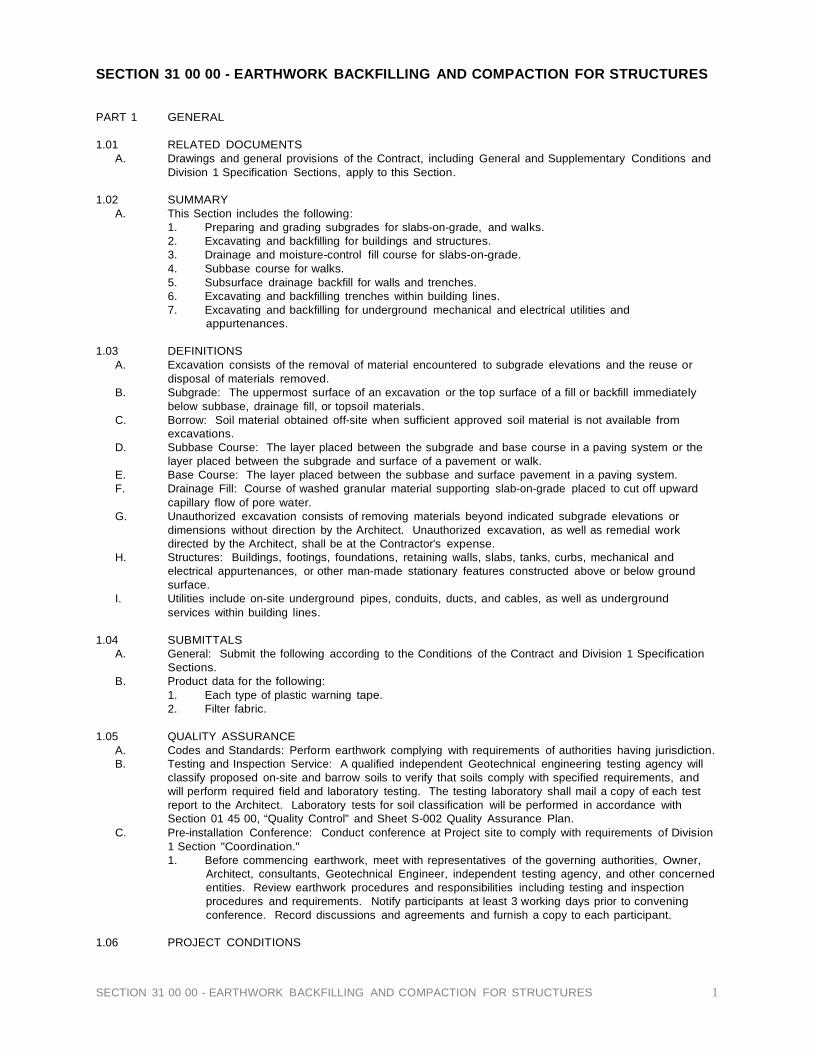
1 SECTION 31 00 00 - EARTHWORK BACKFILLING AND COMPACTION FOR STRUCTURES
SECTION 31 00 00 - EARTHWORK BACKFILLING AND COMPACTION FOR STRUCTURES
PART 1 GENERAL
1.01 RELATED DOCUMENTS A. Drawings and general provisions of the Contract, including General and Supplementary Conditions and
Division 1 Specification Sections, apply to this Section.
1.02 SUMMARY A. This Section includes the following:
1. Preparing and grading subgrades for slabs-on-grade, and walks. 2. Excavating and backfilling for buildings and structures. 3. Drainage and moisture-control fill course for slabs-on-grade. 4. Subbase course for walks. 5. Subsurface drainage backfill for walls and trenches. 6. Excavating and backfilling trenches within building lines. 7. Excavating and backfilling for underground mechanical and electrical utilities and
appurtenances.
1.03 DEFINITIONS A. Excavation consists of the removal of material encountered to subgrade elevations and the reuse or
disposal of materials removed. B. Subgrade: The uppermost surface of an excavation or the top surface of a fill or backfill immediately
below subbase, drainage fill, or topsoil materials. C. Borrow: Soil material obtained off-site when sufficient approved soil material is not available from
excavations. D. Subbase Course: The layer placed between the subgrade and base course in a paving system or the
layer placed between the subgrade and surface of a pavement or walk. E. Base Course: The layer placed between the subbase and surface pavement in a paving system. F. Drainage Fill: Course of washed granular material supporting slab-on-grade placed to cut off upward
capillary flow of pore water. G. Unauthorized excavation consists of removing materials beyond indicated subgrade elevations or
dimensions without direction by the Architect. Unauthorized excavation, as well as remedial work directed by the Architect, shall be at the Contractor's expense.
H. Structures: Buildings, footings, foundations, retaining walls, slabs, tanks, curbs, mechanical and electrical appurtenances, or other man-made stationary features constructed above or below ground surface.
I. Utilities include on-site underground pipes, conduits, ducts, and cables, as well as underground services within building lines.
1.04 SUBMITTALS
A. General: Submit the following according to the Conditions of the Contract and Division 1 Specification Sections.
B. Product data for the following: 1. Each type of plastic warning tape. 2. Filter fabric.
1.05 QUALITY ASSURANCE
A. Codes and Standards: Perform earthwork complying with requirements of authorities having jurisdiction. B. Testing and Inspection Service: A qualified independent Geotechnical engineering testing agency will
classify proposed on-site and barrow soils to verify that soils comply with specified requirements, and will perform required field and laboratory testing. The testing laboratory shall mail a copy of each test report to the Architect. Laboratory tests for soil classification will be performed in accordance with Section 01 45 00, “Quality Control” and Sheet S-002 Quality Assurance Plan.
C. Pre-installation Conference: Conduct conference at Project site to comply with requirements of Division 1 Section "Coordination." 1. Before commencing earthwork, meet with representatives of the governing authorities, Owner,
Architect, consultants, Geotechnical Engineer, independent testing agency, and other concerned entities. Review earthwork procedures and responsibilities including testing and inspection procedures and requirements. Notify participants at least 3 working days prior to convening conference. Record discussions and agreements and furnish a copy to each participant.
1.06 PROJECT CONDITIONS

2 SECTION 31 00 00 - EARTHWORK BACKFILLING AND COMPACTION FOR STRUCTURES
A. Existing Utilities: Do not interrupt existing utilities serving facilities occupied by the Owner or others except when permitted in writing by the Architect and then only after acceptable temporary utility services have been provided. 1. Provide a minimum 48-hours' notice to the Architect and receive written notice to proceed before
interrupting any utility. B. Demolish and completely remove from site existing underground utilities indicated to be removed.
Coordinate with utility companies to shutoff services if lines are active.
PART 2 PRODUCTS
2.01 SOIL MATERIALS A. General: Provide approved borrow soil materials from off-site when sufficient approved soil materials
are not available from excavations. See Geotechnical Report. B. Satisfactory Soil Materials: ASTM D 2487 soil classification groups GW, GP, GM, SW, SP, and SM;
free of rock or gravel larger than 2 inches in any dimension, debris, waste, frozen materials, vegetation and other deleterious matter.
C. Unsatisfactory Soil Materials: ASTM D 2487 soil classification groups GC, SC, ML, MH, CL, CH, OL, OH, and PT.
D. Backfill and Fill Materials: Satisfactory soil materials. E. Subbase and Base Material: Naturally or artificially graded mixture of natural or crushed gravel,
crushed stone, and natural or crushed sand, ASTM D 2940, with at least 95 percent passing a 1- 1/2 inch sieve and not more than 8 percent passing a No. 200 sieve.
F. Engineered Fill: Subbase or base materials. G. Bedding Material: Subbase or base materials with 100 percent passing a 1 inch sieve and not more
than 8 percent passing a No. 200 sieve. H. Drainage Fill: Washed, evenly graded mixture of crushed stone, or crushed or uncrushed gravel,
ASTM D 448, coarse aggregate grading size 57, with 100 percent passing a 1-1/2 inch sieve and not more than 5 percent passing a No. 8 sieve.
I. Filtering Material: Evenly graded mixture of natural or crushed gravel or crushed stone and natural sand, with 100 percent passing a 1-1/2 inch sieve and 0 to 5 percent passing a No. 50 sieve.
J. Impervious Fill: Clayey gravel and sand mixture capable of compacting to a dense state.
2.02 ACCESSORIES A. Warning Tape: Acid- and alkali-resistant polyethylene film warning tape manufactured for marking and
identifying underground utilities, 6 inches wide and 4 mils thick, continuously inscribed with a description of the utility.
B. Detectable Warning Tape: Acid- and alkali-resistant polyethylene film warning tape manufactured for marking and identifying underground utilities, 6 inches wide and 4 mils thick minimum, continuously inscribed with a description of the utility, with metallic core encased in a protective jacket for corrosion protection, detectable by metal detector when tape is buried up to 30 inches deep. 1. Tape Colors: Provide tape colors to utilities as follows:
a. Red: Electric. b. Yellow: Gas, oil, steam, and dangerous materials. c. Orange: Telephone and other communications. d. Blue: Water systems. e. Green: Sewer systems.
C. Filter Fabric: Manufacturer's standard nonwoven pervious geotextile fabric of polypropylene, nylon or polyester fibers, or a combination. 1. Provide filter fabrics that meet or exceed the listed minimum physical properties determined
according to ASTM D 4759 and the referenced standard test method in parentheses: a. Grab Tensile Strength (ASTM D 4632): 100 lb. b. Apparent Opening Size (ASTM D 4751): #100 U.S. Standard sieve. c. Permeability (ASTM D 4491): 150 gallons per minute per sq. ft.
PART 3 EXECUTION
3.01 PREPARATION
A. Protect structures, utilities, sidewalks, pavements, and other facilities from damage caused by settlement, lateral movement, undermining, washout, and other hazards created by earthwork operations.
B. Protect subgrades and foundation soils against freezing temperatures or frost. Provide protective insulating materials as necessary.
C. Provide erosion control measures to prevent erosion or displacement of soils and discharge of soil- bearing water runoff or airborne dust to adjacent properties and walkways.

3 SECTION 31 00 00 - EARTHWORK BACKFILLING AND COMPACTION FOR STRUCTURES
D. Tree protection is specified in 1500-3.06.B.
3.02 DEWATERING A. Prevent surface water and subsurface or ground water from entering excavations, from ponding on
prepared subgrades, and from flooding Project site and surrounding area. B. Protect subgrades and foundation soils from softening and damage by rain or water accumulation.
3.03 EXCAVATION
A. Explosives: Do not use explosives. B. Classified Excavation: Excavation is classified and includes excavation to required subgrade
elevations. Excavation will be classified as earth excavation or rock excavation as follows: 1. Earth excavation includes excavation of pavements and other obstructions visible on surface;
underground structures, utilities, and other items indicated to be demolished and removed; together with soil and other materials encountered that are not classified as rock or unauthorized excavation. a. Intermittent drilling or ripping to increase production and not necessary to permit
excavation of material encountered will be classified as earth excavation.
3.04 STABILITY OF EXCAVATIONS A. Comply with local codes, ordinances, and requirements of authorities having jurisdiction to maintain
stable excavations.
3.05 EXCAVATION FOR STRUCTURES A. Excavate to indicated elevations and dimensions within a tolerance of plus or minus 1.2 inches. Extend
excavations a sufficient distance from structures for placing and removing concrete formwork, installing services and other construction, and for inspections. 1. Excavations for Footings and Foundations: Excavate to rough grade all building and pavement
areas and scarify to a depth of eight inches below rough grade elevations. Any soft and “spongy” areas shall be removed as directed by the geotechnical engineer.
3.06 EXCAVATION FOR WALKS AND PAVEMENTS
A. Excavate surfaces under walks and pavements to indicated cross sections, elevations, and grades.
3.07 EXCAVATION FOR UTILITY TRENCHES A. Excavate trenches to indicated slopes, lines, depths, and invert elevations.
1. Beyond building perimeter, excavate trenches to allow installation of top of pipe below frost line. B. Excavate trenches to uniform widths to provide a working clearance on each side of pipe or conduit.
Excavate trench walls vertically from trench bottom to 12 inches higher than top of pipe or conduit, unless otherwise indicated. 1. Clearance: 12 inches each side of pipe or conduit. 2. Clearance: As indicated
C. Trench Bottoms: Excavate and shape trench bottoms to provide uniform bearing and support of pipes and conduit. Shape subgrade to provide continuous support for bells, joints, and barrels of pipes and for joints, fittings, and bodies of conduits. Remove stones and sharp objects to avoid point loading. 1. For pipes or conduit less than 6 inches in nominal diameter and flat-bottomed, multiple-duct
conduit units, hand-excavate trench bottoms and support pipe and conduit on an undisturbed subgrade.
2. For pipes and conduit 6 inches or larger in nominal diameter, shape bottom of trench to support bottom 90 degrees of pipe circumference. Fill depressions with tamped sand backfill.
3. Where encountering rock or another unyielding bearing surface, carry trench excavation 6 inches below invert elevation to receive bedding course.
3.08 APPROVAL OF SUBGRADE
A. Notify Architect when excavations have reached required subgrade. B. Reconstruct subgrades damaged by freezing temperatures, frost, rain, accumulated water, or
construction activities, as directed by the Architect.
3.09 UNAUTHORIZED EXCAVATION A. Fill unauthorized excavation under foundations or wall footings by extending indicated bottom elevation
of concrete foundation or footing to excavation bottom, without altering required top elevation. Lean concrete fill may be used to bring elevations to proper position when acceptable to the Architect. 1. Fill unauthorized excavations under other construction as directed by the Architect. 2. Where indicated widths of utility trenches are exceeded, provide stronger pipe, or special
installation procedures, as required by the Architect.
3.10 STORAGE OF SOIL MATERIALS
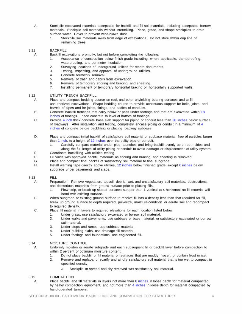
4 SECTION 31 00 00 - EARTHWORK BACKFILLING AND COMPACTION FOR STRUCTURES
A. Stockpile excavated materials acceptable for backfill and fill soil materials, including acceptable borrow materials. Stockpile soil materials without intermixing. Place, grade, and shape stockpiles to drain surface water. Cover to prevent wind-blown dust. 1. Stockpile soil materials away from edge of excavations. Do not store within drip line of
remaining trees.
3.11 BACKFILL A. Backfill excavations promptly, but not before completing the following:
1. Acceptance of construction below finish grade including, where applicable, dampproofing, waterproofing, and perimeter insulation.
2. Surveying locations of underground utilities for record documents. 3. Testing, inspecting, and approval of underground utilities. 4. Concrete formwork removal. 5. Removal of trash and debris from excavation. 6. Removal of temporary shoring and bracing, and sheeting. 7. Installing permanent or temporary horizontal bracing on horizontally supported walls.
3.12 UTILITY TRENCH BACKFILL
A. Place and compact bedding course on rock and other unyielding bearing surfaces and to fill unauthorized excavations. Shape bedding course to provide continuous support for bells, joints, and barrels of pipes and for joints, fittings, and bodies of conduits.
B. Concrete backfill trenches that carry below or pass under footings and that are excavated within 18 inches of footings. Place concrete to level of bottom of footings.
C. Provide 4 inch thick concrete base slab support for piping or conduit less than 30 inches below surface of roadways. After installation and testing, completely encase piping or conduit in a minimum of 4 inches of concrete before backfilling or placing roadway subbase.
D. Place and compact initial backfill of satisfactory soil material or subbase material, free of particles larger
than 1 inch, to a height of 12 inches over the utility pipe or conduit. 1. Carefully compact material under pipe haunches and bring backfill evenly up on both sides and
along the full length of utility piping or conduit to avoid damage or displacement of utility system. E. Coordinate backfilling with utilities testing. F. Fill voids with approved backfill materials as shoring and bracing, and sheeting is removed. G. Place and compact final backfill of satisfactory soil material to final subgrade. H. Install warning tape directly above utilities, 12 inches below finished grade, except 6 inches below
subgrade under pavements and slabs.
3.13 FILL A. Preparation: Remove vegetation, topsoil, debris, wet, and unsatisfactory soil materials, obstructions,
and deleterious materials from ground surface prior to placing fills. 1. Plow strip, or break up sloped surfaces steeper than 1 vertical to 4 horizontal so fill material will
bond with existing surface. B. When subgrade or existing ground surface to receive fill has a density less than that required for fill,
break up ground surface to depth required, pulverize, moisture-condition or aerate soil and recompact to required density.
C. Place fill material in layers to required elevations for each location listed below. 1. Under grass, use satisfactory excavated or borrow soil material. 2. Under walks and pavements, use subbase or base material, or satisfactory excavated or borrow
soil material. 3. Under steps and ramps, use subbase material. 4. Under building slabs, use drainage fill material. 5. Under footings and foundations, use engineered fill.
3.14 MOISTURE CONTROL
A. Uniformly moisten or aerate subgrade and each subsequent fill or backfill layer before compaction to within 2 percent of optimum moisture content. 1. Do not place backfill or fill material on surfaces that are muddy, frozen, or contain frost or ice. 2. Remove and replace, or scarify and air-dry satisfactory soil material that is too wet to compact to
specified density. a. Stockpile or spread and dry removed wet satisfactory soil material.
3.15 COMPACTION
A. Place backfill and fill materials in layers not more than 8 inches in loose depth for material compacted by heavy compaction equipment, and not more than 4 inches in loose depth for material compacted by hand-operated tampers.

5 SECTION 31 00 00 - EARTHWORK BACKFILLING AND COMPACTION FOR STRUCTURES
B. Place backfill and fill materials evenly on all sides of structures to required elevations. Place backfill and fill uniformly along the full length of each structure.
C. Percentage of Maximum Dry Density Requirements: Compact soil to not less than the following percentages of maximum dry density according to ASTM D 1557: 1. Under structures, building slabs, steps, behind retaining walls, and pavements, compact the top
12 inches below subgrade and each layer of backfill or fill material at 95 percent maximum dry density.
2. Under walkways, compact the top 6 inches below subgrade and each layer of backfill or fill material at 95 percent maximum dry density.
3. Under lawn or unpaved areas, and non-structural areas compact the top 6 inches below subgrade and each layer of backfill or fill material at 90 percent maximum dry density.
3.16 GRADING
A. General: Uniformly grade areas to a smooth surface, free from irregular surface changes. Comply with compaction requirements and grade to cross sections, lines, and elevations indicated. 1. Provide a smooth transition between existing adjacent grades and new grades. 2. Cut out soft spots, fill low spots, and trim high spots to conform to required surface tolerances.
B. Site Grading: Slope grades to direct water away from buildings and to prevent ponding. Finish subgrades to required elevations within the following tolerances: 1. Lawn or Unpaved Areas: Plus or minus 1.2 inches. 2. Walks: Plus or minus 1.2 inches. 3. Pavements: Plus or minus 1/2 inch.
C. Grading Inside Building Lines: Finish subgrade to a tolerance of 1/2 inch when tested with a 10 foot straightedge.
3.17 SUBBASE AND BASE COURSES
A. Under pavements and walks, place subbase course material on prepared subgrades. Place base course material over subbases to pavements. 1. Compact subbase and base courses at optimum moisture content to required grades, lines,
cross sections and thickness to not less than 95 percent of ASTM D 4254 relative density. 2. Shape subbase and base to required crown elevations and cross-slope grades. 3. When thickness of compacted subbase or base course is 6 inches or less, place materials in a
single layer. 4. When thickness of compacted subbase or base course exceeds 6 inches, place materials in
equal layers, with no layer more than 6 inches thick or less than 3 inches thick when compacted. B. Pavement Shoulders: Place shoulders along edges of subbase and base course to prevent lateral
movement. Construct shoulders at least 12 inches wide of acceptable soil materials and compact simultaneously with each subbase and base layer.
3.18 FIELD QUALITY CONTROL
A. Testing Agency Services: Allow testing agency to inspect and test each subgrade and each fill or backfill layer. Do not proceed until test results for previously completed work verify compliance with requirements. 1. Perform field in-place density tests according to ASTM D 1556 (sand cone method),
ASTM D 2167 (rubber balloon method), or ASTM D 2937 (drive cylinder method), as applicable. a. Field in-place density tests may also be performed by the nuclear method according to
ASTM D 2922, provided that calibration curves are periodically checked and adjusted to correlate to tests performed using ASTM D 1556. With each density calibration check, check the calibration curves furnished with the moisture gages according to ASTM D 3017.
b. When field in-place density tests are performed using nuclear methods, make calibration checks of both density and moisture gages at beginning of work, on each different type of material encountered, and at intervals as directed by the Architect.
2. Footing Subgrade: At footing subgrades, perform at least one test of each soil stratum to verify design bearing capacities. Subsequent verification and approval of other footing subgrades may be based on a visual comparison of each subgrade with related tested strata when acceptable to the Architect.
3. Paved and Building Slab Areas: At subgrade and at each compacted fill and backfill layer, perform at least one field in-place density test for every 2000 sq. ft. or less of paved area or building slab, but in no case fewer than three tests.
4. Foundation Wall Backfill: In each compacted backfill layer, perform at least one field in-place density test for each 100 feet or less of wall length, but no fewer than two tests along a wall face.
5. Trench Backfill: In each compacted initial and final backfill layer, perform at least one field in- place density test for each 150 feet or less of trench, but no fewer than two tests.

6 SECTION 31 00 00 - EARTHWORK BACKFILLING AND COMPACTION FOR STRUCTURES
B. When testing agency reports that subgrades, fills, or backfills are below specified density, scarify and moisten or aerate, or remove and replace soil to the depth required, recompact and retest until required density is obtained.
3.19 PROTECTION
A. Protecting Graded Areas: Protect newly graded areas from traffic, freezing, and erosion. Keep free of trash and debris.
B. Repair and re-establish grades to specified tolerances where completed or partially completed surfaces become eroded, rutted, settled, or lose compaction due to subsequent construction operations or weather conditions. 1. Scarify or remove and replace material to depth directed by the Architect; reshape and
recompact at optimum moisture content to the required density. C. Settling: Where settling occurs during the Project correction period, remove finished surfacing, backfill
with additional approved material, compact, and reconstruct surfacing. 1. Restore appearance, quality, and condition of finished surfacing to match adjacent work, and
eliminate evidence of restoration to the greatest extent possible.
3.20 DISPOSAL OF SURPLUS AND WASTE MATERIALS A. Disposal: Remove surplus satisfactory soil and waste material, including unsatisfactory soil, trash, and
debris, and legally dispose of it off the Owner's property. END OF SECTION 31 00 00
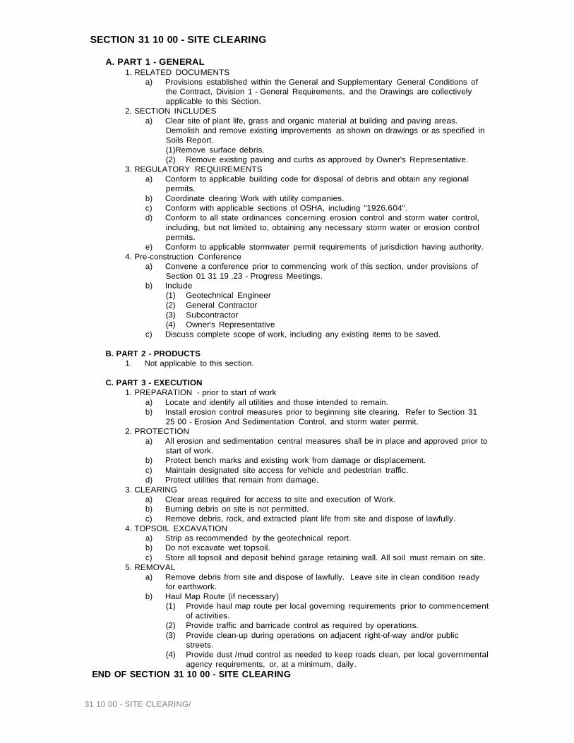
SECTION 31 10 00 - SITE CLEARING
A. PART 1 - GENERAL 1. RELATED DOCUMENTS
a) Provisions established within the General and Supplementary General Conditions of the Contract, Division 1 - General Requirements, and the Drawings are collectively applicable to this Section.
2. SECTION INCLUDES a) Clear site of plant life, grass and organic material at building and paving areas.
Demolish and remove existing improvements as shown on drawings or as specified in Soils Report. (1)Remove surface debris. (2) Remove existing paving and curbs as approved by Owner's Representative.
3. REGULATORY REQUIREMENTS a) Conform to applicable building code for disposal of debris and obtain any regional
permits. b) Coordinate clearing Work with utility companies. c) Conform with applicable sections of OSHA, including "1926.604". d) Conform to all state ordinances concerning erosion control and storm water control,
including, but not limited to, obtaining any necessary storm water or erosion control permits.
e) Conform to applicable stormwater permit requirements of jurisdiction having authority. 4. Pre-construction Conference
a) Convene a conference prior to commencing work of this section, under provisions of Section 01 31 19 .23 - Progress Meetings.
b) Include (1) Geotechnical Engineer (2) General Contractor (3) Subcontractor (4) Owner's Representative
c) Discuss complete scope of work, including any existing items to be saved.
B. PART 2 - PRODUCTS 1. Not applicable to this section.
C. PART 3 - EXECUTION
1. PREPARATION - prior to start of work a) Locate and identify all utilities and those intended to remain. b) Install erosion control measures prior to beginning site clearing. Refer to Section 31
25 00 - Erosion And Sedimentation Control, and storm water permit. 2. PROTECTION
a) All erosion and sedimentation central measures shall be in place and approved prior to start of work.
b) Protect bench marks and existing work from damage or displacement. c) Maintain designated site access for vehicle and pedestrian traffic. d) Protect utilities that remain from damage.
3. CLEARING a) Clear areas required for access to site and execution of Work. b) Burning debris on site is not permitted. c) Remove debris, rock, and extracted plant life from site and dispose of lawfully.
4. TOPSOIL EXCAVATION a) Strip as recommended by the geotechnical report. b) Do not excavate wet topsoil. c) Store all topsoil and deposit behind garage retaining wall. All soil must remain on site.
5. REMOVAL a) Remove debris from site and dispose of lawfully. Leave site in clean condition ready
for earthwork. b) Haul Map Route (if necessary)
(1) Provide haul map route per local governing requirements prior to commencement of activities.
(2) Provide traffic and barricade control as required by operations. (3) Provide clean-up during operations on adjacent right-of-way and/or public
streets. (4) Provide dust /mud control as needed to keep roads clean, per local governmental
agency requirements, or, at a minimum, daily. END OF SECTION 31 10 00 - SITE CLEARING
31 10 00 - SITE CLEARING/

31 22 19 - SITE FINISH GRADING 1
SECTION 31 22 19 - SITE FINISH GRADING
A. PART 1 GENERAL 1. RELATED DOCUMENTS
a) Provisions established within the General and Supplementary General Conditions of the Contract, Division 1 - General Requirements, and the Drawings are collectively applicable to this Section.
2. DESCRIPTION a)This Section covers all work necessary to place topsoil material to finish grade; remove or
handle all rock encountered subsequent to clearing and rough grading, remove grass, weeds, construction debris, or other foreign objects and detrimental substances; soil handling and general preparation of landscaped areas as denoted on plans.
3. RELATED WORK a)Section 31 10 00 - Site Clearing. b)Section 31 22 00 - Building Earthwork. c)Section 32 90 00 - Landscaping.
4. PROTECTION a)Protect and maintain existing plant materials to be preserved as denoted on plan. Protect
all other existing features such as fences, roads, sidewalks, paving, and curbs as final work.
B. PART 2 PRODUCTS
1. TOPSOIL a) The topsoil shall be a natural friable soil, possessing characteristics of representative
productive soils from the construction site. The topsoil shall be reasonably free from subsoil, clay lumps, stone, or similar objects larger than 1-inch in greatest diameter, brush, stumps, roots, objectionable weeds or litter, excess acid or alkali, or any other material or substance which may be harmful to plant growth or a hindrance to subsequent smooth grading, and maintenance operations.
b) Soil pH shall be 5.5 to 7.5. Provide certification of import material if used.
C. PART 3 EXECUTION 1. EQUIPMENT
a) Contractor shall furnish and maintain earth-moving, leveling, raking, and compacting equipment in satisfactory condition and shall operate such equipment as necessary to control uniform density, and smoothness.
2. INSPECTION a) Verify site conditions and note irregularities affecting work of this Section. b) Beginning work of this Section means acceptance of existing conditions.
3. SUBSOIL PREPARATION a) Eliminate uneven areas, humps, and low spots. Remove and lawfully dispose of
subsoils contaminated with chemical compounds deleterious to healthy plant growth. b) Scarify subgrade to depth of 3-inches where topsoil is to be placed. Scarify in areas
where equipment has overly compacted subsoils. 4. EXCAVATION HANDLING
a) Remove all foreign matter obtained from site soil cleaning, screening and/or picking process from the site and legally dispose of as required by the appropriate jurisdiction. Dispose of all waste off-site.
5. PLACEMENT a) Source of topsoil for finish grading shall be stockpiled site soils, placed during site
clearing and rough grading. or imported top soil as needed to achieve specified final grades.
b) All landscaped fill areas shall be constructed in lifts not exceeding 12-inches in loose depth using site topsoils. Each lift shall be uniformly compacted to the specified density per the soils report.
c) Topsoil placement shall not be performed when satisfactory results cannot be obtained due to rain, freezing weather, or other unsatisfactory conditions.
d) To be suitable for shaping, topsoil shall not contain rocks, stones, sticks or other debris in excess of 1-inch in diameter, or stones of smaller sizes in concentrations more than twenty percent (10%) by soil volume.
e) Rocks, stones, sticks, brush, roots, and other objectionable materials which might reasonably interfere with the formation of a finely pulverized seed bed, shall be

31 22 19 - SITE FINISH GRADING 2
removed from the soil and disposed of off-site as herein specified. f) All areas to be planted shall be graded and floated to positively drain away from
buildings and eliminate water holding depressions and pockets. Storm water shall flow swiftly, positively and continuously away from buildings without ponding.
g) All planted areas shall be machine or hand worked to eliminate objectionable lumps and soil clods, as deemed necessary by the Owner's Representative. Tillage shall include the removal of all equipment ruts and tracks, areas of compaction or erosion, and any other undesirable soil conditions which would prevent the proper formation of a finely pulverized seedbed, or level smooth turf areas, as directed by Owner's Representative.
h) Undulations and unsightly variations in grade that will not permit the use of normal mowing equipment without scalping or missing shall be re-graded and floated to smooth surfaces.
i) Grading tolerance shall be within 1/2-inch of elevations shown on plans. Contractor to review grades and verify positive drainage before proceeding with irrigation and plantings.
6. ROCK PICKUP AND REMOVAL a) Loose rocks or stones encountered during finish grading that are larger than 1-inch
diameter but smaller than 12-inches diameter shall be removed and placed in random areas throughout the undisturbed on-site area. Rocks or stones larger than 12-inches diameter shall be stockpiled on-site and reviewed for use by Landscape Architect.
b) Loose rock or stones under 1-inch diameter should not impede the formation of a satisfactory seedbed, provided they are not concentrated in any one area. Concentration in excess of twenty percent (10%) by volume of any random sample is not acceptable. Such areas must either be re-worked or covered with suitable soil.
c) Contractor shall leave all fine graded areas in a condition that is acceptable to the Owner's Representative, and landscape subcontractor.
7. IMPROVEMENTS PROTECTION a) Contractor shall be responsible for protecting all existing water lines, underground
utilities and any other subsurface features while excavating and working on the project site.
b) Contractor shall protect all surface hardscape features from damage while excavating and working on the project site and shall clean landscape features soiled by grading subcontractor.
c) Contractor shall be responsible for all above grade improvements, amenities and structures damaged by his equipment.
8. MAINTENCE a) Positive drainage away from buildings and final grades shall be maintained and
regraded as necessary throughout the construction phase of the project until final work is accepted by owner and as per civil drawings.
END OF SECTION 31 22 19 - SITE FINISH GRADING

I. SECTION 31 25 00 - EROSION AND SEDIMENTATION CONTROL
31 25 00 - EROSION AND SEDIMENTATION CONTROL
A. PART 1 GENERAL
1. RELATED DOCUMENTS a) Provisions established within the General and Supplementary General Conditions of the Contract,
Division 1 - General Requirements, and the Drawings are collectively applicable to this Section. 2. DESCRIPTION
a) This Section pertains to the provisions for the control of erosion in the construction area and in stockpile areas including seeding, sodding, hydromulching, silt fences, sediment barriers, the construction of temporary swales and sedimentation basins as required and shown on the drawings.
b) Contractor is responsible for meeting all Local, State and Federal regulations regarding erosion control including the applicable provisions of the National Pollution Discharge Elimination System (NPDES) regulations from the Federal Clean Water Act and SWPP requirements.
c) Contractor is responsible for maintaining and inspecting erosion control measures.
B. PART 2 PRODUCTS 1. GRASS
a) Materials for seeding and sodding shall conform to Section 32 90 00 - Landscaping. 2. FERTILIZER
a) Use commercial grade fertilizers to insure germination and growth. Analysis by weight shall be 16-4-8 or 15-5-10 for Nitrogen, Phosphoric Acid and Potash, or as recommended by landscape architect.
3. WATER a) Use clean potable water for maintaining the grass.
4. SILT FENCE a) Lundin "Silt Buster", Mirafi "Envirofence", or approved equal.
5. STRAW BALES a) Standard rectangular hay bales bound by baling wire.
6. SEDIMENT TRAPS a) Standard manufacture designed to fit the intended inlet.
7. BIO-BAGS a) Bio-filter bags shall be clean 100 percent recycled wood product waste. Size of bag shall be 18 x 8 x 30
inches and weigh approximately 45 pounds, and made of 1/2-inch plastic mesh.
C. PART 3 EXECUTION 1. GENERAL
a) Contractor shall keep disturbed areas to a minimum required to adequately perform the work. At all times the Contractor shall maintain the site in such a manner that minimizes erosion of the site. The execution of work under this section shall be in conformance with the NPDES rulings and the site Storm Water Pollution Prevention Plan.
2. SEEDING a) Disturbed portions of the site and stockpile areas shall be seeded within 14-days if the phasing of the
construction operations are anticipated to leave those portions of the areas unworked for 21-days or more.
b) Seeded areas shall be maintained until the project is accepted by the Owner's Representative. Maintenance shall include but not be limited to watering, fertilizing, reseeding, mowing and erosion repair as may be required. Grass shall be cut when the average height of the grass reaches 6-inches. Clippings may be mulched back into the seeded areas.
3. TEMPORARY AND PERMANENT SWALES a) Description
(1) Temporary and permanent drainage swales shall be provided as required to carry drainage away from the work area to an approved outfall point.
(2) Unless otherwise shown on the drawings, swales shall be earthen "V" shaped channels graded to a sufficient depth and slope to carry the anticipated runoff, but at least 2-feet deep with a slope of 1.0%.
(3) Swales not designated to remain in place at the completion of the contract shall be cleaned of any much, debris and other unsuitable material and filled with approved fill before final grading operations begin.
(4) Swales shall have erosion control barriers as required. (5) All permanent swales shall be sodded to a minimum width of 10-feet on either side of the centerline
of the swale. b) Maintenance
(1) During the course of construction, all temporary swales constructed for this contract shall be maintained so as to allow proper drainage from the construction area without allowing silt-laden discharge. Before Contractor leaves the site at the end of construction, all erosion control facilities

31 25 00 - EROSION AND SEDIMENTATION CONTROL
to remain shall be placed in good working condition.
(2) Contractor shall work with other contractors at the site in maintaining existing swales and ditches. (3) Where necessary for access to the work areas, adequately sized culverts shall be installed and
maintained to provide the access without disturbing the site drainage. (4) Care shall be taken not to rut and damage sodded swales. Damaged swales shall be repaired
immediately. (5) Keep sodded swales mowed.
4. DRAINAGE DITCHES a) Drainage ditches shall be hydromulched immediately upon final grading. b) Erosion of the banks of the drainage ditches shall be repaired immediately and re-stabilized. c) Sediment barriers shall be placed at intervals along the ditch as shown on the plans and as necessary to
trap sediment on the site. Sediment and other debris trapped by the barriers shall be removed on a daily basis as needed.
d) Ditch side slopes shall not be steeper than 3-feet horizontal to 1-foot vertical. e) Maintenance of the ditches during construction shall include but not be limited to mowing, re-grading,
sediment removal, re-hydromulching, bank repair and debris removal. f) Sediment removed from the ditches may be re-spread on the site as directed by the Owner.
5. FILL AND CUT SLOPES a) Fill slopes in all cases shall be no steeper than 3:1 unless specifically stated on the plans or approved by
the Owner's soils engineer. b) When cut slopes exceed 2:1 for depths over 3-feet, proper bracing and shoring per OSHA requirements
shall be used and maintained. c) For permanent slopes, cut or fill, between 2:1 and 10:1, erosion protection shall be provided with
hydromulching, sodding, seeding, or other method as approved. 6. SEDIMENTATION BASINS
a) Description (1) Sedimentation ponds shall be provided where designated on the plans. (2) All drainage from cleared areas shall be routed through the sedimentation basin. (3) Contractor will be responsible for the operation and maintenance of the pond during construction.
b) Maintenance. (1) Contractor shall be responsible for maintaining the pond and the outfall and sediment retarding
structure in good working condition throughout the time the pond is to be in operation. (2) When sediment and debris fill the pond to over one-fourth (1/4) its designed capacity, the pond shall
be cleaned out. (3) The sediment from the clearing operation shall be stockpiled in its own separate area or removed
from the site, as required, and adequate drainage provisions must be made such that drainage from the sediment stockpile drains back into the sediment pond. When approved by the Owner's Representative, sediment removed from the pond may be spread over the site.
7. EROSION CONTROL BARRIERS a) Erosion control barriers shall be provided at intervals along swales and ditches as shown on the drawings
and as necessary to meet the requirements of the Storm Water Pollution Prevention Plan. b) The barriers shall be silt fence, hay bales, or bio bags placed as shown on the drawings and details. c) Barriers shall be maintained in good working condition and replaced when damaged.
II. END OF SECTION 31 25 00 - EROSION AND SEDIMENTATION CONTROL

SECTION 32 17 13 Parking Bumpers A. PART 1 - GENERAL
1. SUMMARY a) Related Sections
(1) Section (NONE): None 2. REFERENCES
a) Standard of the Following as Referenced (1) American National Standards Institute (ANSI) (2) Federal Specification (Fed. Spec.) (3) Underwriters' Laboratories, Inc. (UL)
3. SYSTEM DESCRIPTION a) Design Requirements
(1) EAGLE Poly Parking Stops or equal. 4. DELIVERY, STORAGE, AND HANDLING
a) Storage (1) Stock perpendicular to trusses on floors. Stock per manufacturer’s specifications. (2) Do not overload floor system.
5. PROJECT CONDITIONS a) Install parking stops after building is completed, and as required by plans, local codes and
ordinances.
B. PART 2 - PRODUCTS 1. MANUFACTURERS
a) Acceptable manufacturers: Products of the following manufacturers are acceptable for use except certain manufacturer's products may be required for use in particular rated assemblies. Those rated products ONLY are acceptable for use. (1) EAGLE 72 x 8” x 4”
C. PART 3 - EXECUTION
1. INSTALLATION a) Install per manufacturer’s instructions.
END SECTION 32 17 13 Parking Bumpers
32 17 13 Parking Bumpers
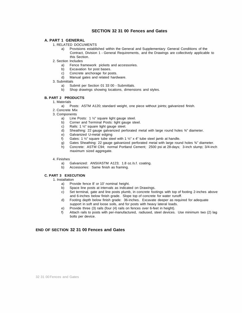
SECTION 32 31 00 Fences and Gates
A. PART 1 GENERAL 1. RELATED DOCUMENTS
a) Provisions established within the General and Supplementary General Conditions of the Contract, Division 1 - General Requirements, and the Drawings are collectively applicable to this Section.
2. Section Includes a) Fence framework pickets and accessories. b) Excavation for post bases. c) Concrete anchorage for posts. d) Manual gates and related hardware.
3. Submittals a) Submit per Section 01 33 00 - Submittals. b) Shop drawings showing locations, dimensions and styles.
B. PART 2 PRODUCTS
1. Materials a) Posts: ASTM A120; standard weight, one piece without joints; galvanized finish.
2. Concrete Mix 3. Components
a) Line Posts: 1 ½” square light gauge steel. b) Corner and Terminal Posts: light gauge steel. c) Rails: 1 ½” square light gauge steel. d) Sheathing: 22 gauge galvanized perforated metal with large round holes ¾” diameter. e) Galvanized U-metal edging f) Gates: 1 ½” square tube steel with 1 ½” x 4” tube steel jamb at handle. g) Gates Sheathing: 22 gauge galvanized perforated metal with large round holes ¾” diameter. h) Concrete: ASTM C94; normal Portland Cement; 2500 psi at 28-days; 3-inch slump; 3/4-inch
maximum sized aggregate.
4. Finishes a) Galvanized: ANSI/ASTM A123; 1.8 oz./s.f. coating. b) Accessories: Same finish as framing.
C. PART 3 EXECUTION
1. Installation a) Provide fence 8’ or 10’ nominal height. b) Space line posts at intervals as indicated on Drawings. c) Set terminal, gate and line posts plumb, in concrete footings with top of footing 2-inches above
and 6-inches below finish grade. Slope top of concrete for water runoff. d) Footing depth below finish grade: 36-inches. Excavate deeper as required for adequate
support in soft and loose soils, and for posts with heavy lateral loads. e) Provide three (3) rails (four (4) rails on fences over 6-feet in height). f) Attach rails to posts with per-manufactured, radiused, steel devices. Use minimum two (2) lag
bolts per device. END OF SECTION 32 31 00 Fences and Gates
32 31 00 Fences and Gates

32 90 00 – LANDSCAPING
Pag
e1
SECTION 32 90 00 - LANDSCAPING
PART 1 GENERAL RELATED DOCUMENTS
A) Provisions established within the General and Supplementary General Conditions of the Contract, Division 1 - General Requirements, and the Drawings are collectively applicable to this Section.
B) Contractor will provide up to $50,000 for design and installation of landscaping and irrigation system.
SECTION I: GENERAL CONDITIONS A) Permits and License:
(1) The Contractor shall, at his own expense, procure all permits, certificates, and licenses required of him by law for the execution of his work. He shall also comply with all state, county, or local laws, ordinances, rules or regulations relating to the performance of his work.
B) Responsibility: (1) The Contractor assumes full responsibility for the safekeeping of all materials and equipment and for
the protection of all unfinished work, until final acceptance by the Owner. If any of the work is damaged or destroyed from any cause, the Contractor shall replace it at his own expense. The Subcontractor must indemnity and save harmless the Owner, General Contractor, or Construction Manager, against any claims filed for non-payment of his bills for Subcontractors, labor, and materials used in connection with the contract work.
(2) The Subcontractor shall fully coordinate his work with the General Contractor and the Owner's representative.
C) Removal of Defective and Unauthorized Work: (1) All work which has been rejected for non-compliance to plans and specification shall be remedied or
removed and replaced in an acceptable manner by the Contractor at his own expense. No compensation shall be allowed for such removal or replacement.
D) Guarantee of Work: (1) The Contractor shall guarantee all work against defective material and workmanship for a period of
one (1) year from the date of the final acceptance of the contract work.
SECTION II: SPECIAL CONDITIONS A) General:
(1) All of the provisions of Section I shall apply to this Section. B) Examination of Premises:
(1) The Subcontractor shall assume all responsibility for that portion of the site involved in the project work and shall provide and maintain all necessary protection, as required by the state and local codes, ordinances, or laws. Subcontractors shall be responsible for damage caused to work that is not properly protected.
(2) The Subcontractor shall be responsible for contacting underground utility companies and communicating the hazards of underground work, and accepts the responsibility for repair of any damage to utilities.
(3) The Subcontractor shall provide enclosures, ditches, or drains to protect installation and improvements within the working area subject to damage by weather conditions, and shall repair or replace any damaged structures or improvements.
(4) Any damage incurred to existing structures or installations by the Subcontractor will be replaced and repaired to original condition at the Subcontractor's expense to the approval of the Owner's Representative.
C) Obstructions: (1) Obstructions, if encountered, shall be reported to the Owner's Representative. Clean-up of trash,
debris, or other obstructions resulting from work performed by other trades is not the responsibility of the Subcontractor.
D) Inspection of Construction Work: (1) Periodic site inspection will be made by the Owner's Representative to determine quality and
compliance of work with contract documents. (2) Inspection of work for compliance with City codes and Standards shall be by the City Inspectors.
E) Cleaning: (1) The Subcontractor shall remove debris, waste, rubbish, or unused construction materials from the
project areas resulting from work under this contract daily. F) Workmanship:
(1) The Subcontractor shall be responsible for providing competent workmen. All work shall be undertaken and finished in quality workmanship. Any work that does not show quality workmanship by skilled workmen, in the opinion of the Owner's Representative shall be replaced or repaired as directed by the Owner's Representative, and at the Subcontractor's expense.
G) Maintenance Period: The Subcontractor, after acceptance of the project, or portion thereof, by Owner, shall provide thirty (30) days maintenance. Maintenance shall consist of all operations necessary or required to maintain the project.
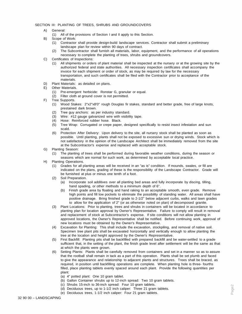
32 90 00 – LANDSCAPING
Pag
e2
SECTION III: PLANTING OF TREES, SHRUBS AND GROUNDCOVERS A) General:
(1) All of the provisions of Section I and II apply to this Section. B) Scope of Work:
(1) Contractor shall provide design-build landscape services. Contractor shall submit a preliminary landscape plan for review within 90 days of contract.
(2) The Subcontractor shall furnish all materials, labor, equipment, and the performance of all operations necessary to complete the planting of trees, shrubs and groundcovers.
C) Certificates of Inspections: (1) All shipments or orders of plant material shall be inspected at the nursery or at the growing site by the
authorized federal and state authorities. All necessary inspection certificates shall accompany the invoice for each shipment or order of stock, as may be required by law for the necessary transportation, and such certificates shall be filed with the Contractor prior to acceptance of the materials.
D) Plant Materials: as detailed on plans. E) Other Materials.
(1) Pre-emergent herbicide: Ronstar G, granular or equal. (2) Filter cloth at ground cover is not permitted.
F) Tree Supports. (1) Wood Stakes: 2"x2"x8'0" rough Douglas fir stakes, standard and better grade, free of large knots,
prestained dark brown. (2) Tree guy anchors: as per industry standard. (3) Wire: #12 gauge galvanized wire with visibility tape. (4) Hose: Reinforced rubber hose. Black. (5) Tree Wrap: Corrugated or crepe paper, designed specifically to resist insect infestation and sun
scald. (6) Protection After Delivery: Upon delivery to the site, all nursery stock shall be planted as soon as
possible. Until planting, plants shall not be exposed to excessive sun or drying winds. Stock which is not satisfactory in the opinion of the Landscape Architect shall be immediately removed from the site at the Subcontractor's expense and replaced with acceptable stock.
G) Planting Season: (1) The planting of trees shall be performed during favorable weather conditions, during the season or
seasons which are normal for such work, as determined by acceptable local practice. H) Planting Operations.
(1) Grades for all planting areas will be received in an "as is" condition. If mounds, swales, or fill are indicated on the plans, grading of these is the responsibility of the Landscape Contractor. Grade will be furnished at plus or minus one tenth of a foot.
(2) Soil Preparation. (a) Incorporate soil additives over all planting bed areas and fully incorporate by discing, tilling,
hand spading, or other methods to a minimum depth of 6". (b) Finish grade area by floating and hand raking to an acceptable smooth, even grade. Remove
high points and fill low pockets to eliminate the possibility of standing water. All areas shall have positive drainage. Bring finished grade to 2-1/2" below adjacent curbs, walks and lawn grades to allow for the application of 2" (or as otherwise noted on plan) of decomposed granite.
(3) Plant Locations: Prior to planting, trees and shrubs in containers will be located in accordance to planting plan for location approval by Owner's Representative. Failure to comply will result in removal and replacement of stock at Subcontractor's expense. If site conditions will not allow planting in approved locations, the Owner's Representative shall be notified. Before continuing work, approval of new locations must be obtained by the Owner's Representative.
(4) Excavation for Planting: This shall include the excavation, stockpiling, and removal of native soil. Specimen tree plant pits shall be excavated horizontally and vertically enough to allow planting the tree at the location and height approved by the Owner's Representative.
(5) First Backfill: Planting pits shall be backfilled with prepared backfill and be water-settled to a grade sufficient that, in the setting of the plant, the finish grade level after settlement will be the same as that at which the plants were grown.
(6) Setting Plants: Plants shall be carefully removed from containers and set in a manner so as to assure that the rootball shall remain in tack as a part of this operation. Plants shall be set plumb and faced to give the appearance and relationship to adjacent plants and structures. Trees shall be braced, as required, in position until backfilling operations are complete. When planting hole is three- fourths filled, place planting tablets evenly spaced around each plant. Provide the following quantities per plant: (a) 4" potted plant: One 10 gram tablet. (b) Gallon Container shrubs up to 12-inch spread: Two 10 gram tablets. (c) Shrubs 15-inch to 36-inch spread: Four 10 gram tablets. (d) Deciduous trees, up to 1-1/2 inch caliper: Three 21 gram tablets. (e) Deciduous trees, 1-1/2 inch caliper: Four 21 gram tablets.
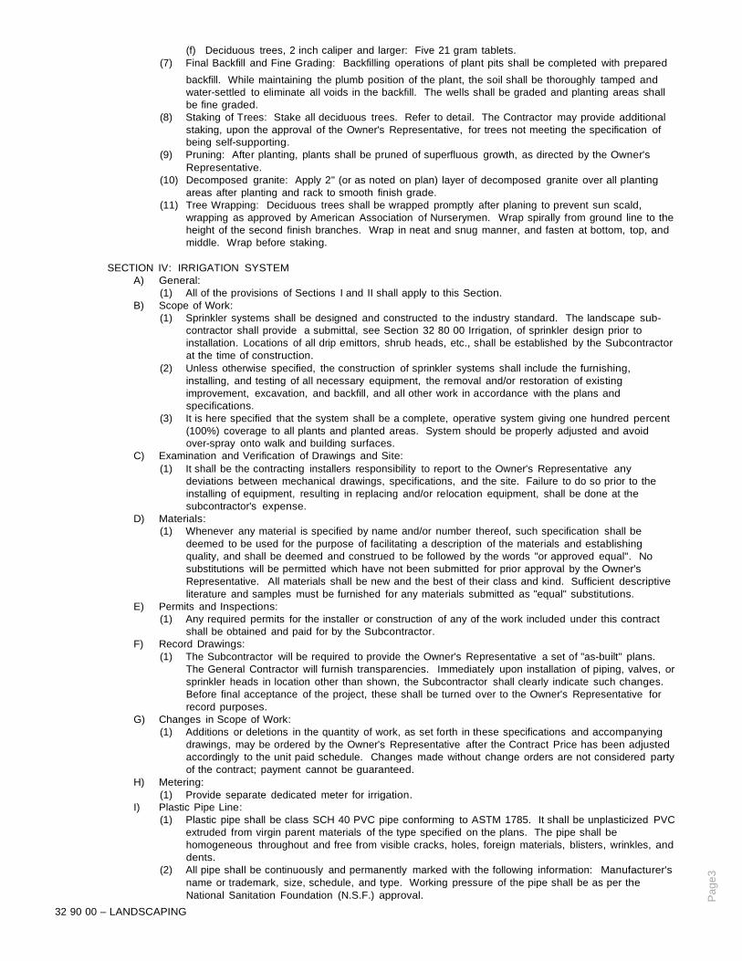
32 90 00 – LANDSCAPING
Pag
e3
(f) Deciduous trees, 2 inch caliper and larger: Five 21 gram tablets. (7) Final Backfill and Fine Grading: Backfilling operations of plant pits shall be completed with prepared
backfill. While maintaining the plumb position of the plant, the soil shall be thoroughly tamped and water-settled to eliminate all voids in the backfill. The wells shall be graded and planting areas shall be fine graded.
(8) Staking of Trees: Stake all deciduous trees. Refer to detail. The Contractor may provide additional staking, upon the approval of the Owner's Representative, for trees not meeting the specification of being self-supporting.
(9) Pruning: After planting, plants shall be pruned of superfluous growth, as directed by the Owner's Representative.
(10) Decomposed granite: Apply 2" (or as noted on plan) layer of decomposed granite over all planting areas after planting and rack to smooth finish grade.
(11) Tree Wrapping: Deciduous trees shall be wrapped promptly after planing to prevent sun scald, wrapping as approved by American Association of Nurserymen. Wrap spirally from ground line to the height of the second finish branches. Wrap in neat and snug manner, and fasten at bottom, top, and middle. Wrap before staking.
SECTION IV: IRRIGATION SYSTEM
A) General: (1) All of the provisions of Sections I and II shall apply to this Section.
B) Scope of Work: (1) Sprinkler systems shall be designed and constructed to the industry standard. The landscape sub-
contractor shall provide a submittal, see Section 32 80 00 Irrigation, of sprinkler design prior to installation. Locations of all drip emittors, shrub heads, etc., shall be established by the Subcontractor at the time of construction.
(2) Unless otherwise specified, the construction of sprinkler systems shall include the furnishing, installing, and testing of all necessary equipment, the removal and/or restoration of existing improvement, excavation, and backfill, and all other work in accordance with the plans and specifications.
(3) It is here specified that the system shall be a complete, operative system giving one hundred percent (100%) coverage to all plants and planted areas. System should be properly adjusted and avoid over-spray onto walk and building surfaces.
C) Examination and Verification of Drawings and Site: (1) It shall be the contracting installers responsibility to report to the Owner's Representative any
deviations between mechanical drawings, specifications, and the site. Failure to do so prior to the installing of equipment, resulting in replacing and/or relocation equipment, shall be done at the subcontractor's expense.
D) Materials: (1) Whenever any material is specified by name and/or number thereof, such specification shall be
deemed to be used for the purpose of facilitating a description of the materials and establishing quality, and shall be deemed and construed to be followed by the words "or approved equal". No substitutions will be permitted which have not been submitted for prior approval by the Owner's Representative. All materials shall be new and the best of their class and kind. Sufficient descriptive literature and samples must be furnished for any materials submitted as "equal" substitutions.
E) Permits and Inspections: (1) Any required permits for the installer or construction of any of the work included under this contract
shall be obtained and paid for by the Subcontractor. F) Record Drawings:
(1) The Subcontractor will be required to provide the Owner's Representative a set of "as-built" plans. The General Contractor will furnish transparencies. Immediately upon installation of piping, valves, or sprinkler heads in location other than shown, the Subcontractor shall clearly indicate such changes. Before final acceptance of the project, these shall be turned over to the Owner's Representative for record purposes.
G) Changes in Scope of Work: (1) Additions or deletions in the quantity of work, as set forth in these specifications and accompanying
drawings, may be ordered by the Owner's Representative after the Contract Price has been adjusted accordingly to the unit paid schedule. Changes made without change orders are not considered party of the contract; payment cannot be guaranteed.
H) Metering: (1) Provide separate dedicated meter for irrigation.
I) Plastic Pipe Line: (1) Plastic pipe shall be class SCH 40 PVC pipe conforming to ASTM 1785. It shall be unplasticized PVC
extruded from virgin parent materials of the type specified on the plans. The pipe shall be homogeneous throughout and free from visible cracks, holes, foreign materials, blisters, wrinkles, and dents.
(2) All pipe shall be continuously and permanently marked with the following information: Manufacturer's name or trademark, size, schedule, and type. Working pressure of the pipe shall be as per the National Sanitation Foundation (N.S.F.) approval.

32 90 00 – LANDSCAPING
Pag
e4
J) Plastic Pipe Fittings and Connections: (1) All plastic pipe fittings to be installed shall be molded fittings manufactured to the same materials as
the pipe and shall be suitable for either solvent weld or screwed connections. No fittings made of other materials shall be used. Fittings shall be marked with manufacturer's name, size, and schedule information.
(2) Slip fitting socket taper shall be so sized that a dry, unsoftened pipe end conforming to these special provisions can be inserted no more than half way into the socket. Plastic saddle and flange fittings will not be permitted. Unless otherwise specified, all plastic fitting shall be of PVC Schedule 40 material.
(3) All plastic to metal joints shall be made of PVC Schedule 40 male adapters or PVC Schedule 80 nipples. Joint compound for such connections shall be Permatex Type II or Teflon tape.
(4) Primer and solvent for socket connections of PVC material shall be compatible with material to be welded, as recommended by the plastic material manufacturer.
K) Polyethylene Pipe: (1) Polyethylene pipe shall be as described on the drawings. Sizes may include .580" I.D., .375" I.D.,
and .125" I.D. pipe. (2) Polyethylene pipe sizes .580" and larger shall be continuously and permanently marked with the
following information: Manufacturer's name, size, material, and design strength. (3) The pipe shall be homogeneous throughout and free from visible cracks, holes, foreign materials,
blisters, wrinkles, dents, and variations in size. L) Polyethylene Fittings:
(1) All polyethylene pipe fitting to be installed shall be molded fitting of plastic material. Fittings shall be compression type fittings designed or sized for use with the specific brand of pipe to be used for construction.
M) Sprinkler Heads and Risers: (1) Sprinkler heads shall be of the types and sizes shown on the plans. (2) All heads of the particular type of function in the system shall be of the same manufacturer and shall
be marked with the manufacturer's name and identification in such a position that they can be identified without being removed from the system.
N) Emitter Installation: (1) Emitters shall be as specified on the plans. (2) Emitter to riser adapters shall be as specified on the plans. (3) Emitter riser pipe shall be as per detail on the plan.
O) Plastic Enclosures for Equipment: (1) Enclosures of equipment set below finish grade shall be plastic irrigation valve boxes and/or pits with
lids, the type and size being determined by the volume of equipment to be enclosed. Enclosures shall be manufactured by Carson or an approved equal.
P) Equipment: (1) Controllers shall be as specified on the plan. Contractors shall take special note of information on
plans regarding possible duel programming capabilities. (2) Valves, backflow preventers, and filters shall be as specified on the plans.
Q) Irrigation Control Cable: (1) All wiring to be used for connecting the automatic controller to the electric solenoid actuated remote
control valve shall be Type UF-600V, seven (7) strand or solid copper PVC insulation, single conductor, UL approved underground feeder cable. All pilot or "hot" wires are to be one color and all "common" wires are to be of another color.
(2) Connectors shall be waterproof type, as manufactured by Pentite or an approved equal. R) Trenching:
(1) Unless otherwise indicated on the plans, all main lines shall be a minimum cover of eighteen inches (18"), and all lateral lines shall be installed with a minimum cover of twelve inches (12") based on finish grades. Sprinkler lines connecting rotor pop-up sprinklers shall be installed with a minimum cover of fifteen inches (15") based on finish grades. All plastic lines installed beneath A.C. paving shall have a minimum of a twenty-four inch (24") cover and backfill shall meet the compaction test of the area involved.
(2) Alignment of pipe shall be for a simple layout with pipe running parallel or perpendicular to features such as curbs, sidewalks, and buildings, as may be possible with on-site conditions.
S) Installation of Plastic Pipe and Fittings: (1) Plastic pipe shall be installed in a manner so as to provide for expansion and contraction, as
recommended by the manufacturer. (2) Plastic pipe shall be cut with a handsaw or hacksaw with the assistance of squared-in sawing vise, or
in a manner so as to ensure a square cut. Burrs at cut ends shall be removed prior to installation so that smooth unobstructed flow will be obtained.
(3) Solvent welded connections shall be made using primer and/or solvent compatible with pipe. Pipe sizes up to and including one inch (1") diameter shall be solvent welded. Pipe sizes up to and including one and one-quarter inches (1-1/4") diameter and larger shall be primed prior to the application of the solvent. Pipe shall be fully inserted in all sockets. Any excess solvent shall be removed from joint connectors.
(4) Threaded male adapters shall be compounded, as per manufacturer's recommendation. Adapter

32 90 00 – LANDSCAPING
Pag
e5
shall then be hand-tightened, plus one turn with a strap wrench. (5) Piping under paved areas shall be sleeved in PVC Schedule 40 pipe, as shown on the drawings. In
other cases, piping under paving shall be installed by jacking, boring, or hydraulic driving. Where any cutting or breaking of sidewalks and/or concrete work is necessary, it shall be removed and replaced by the Subcontractor. Permission to cut or break sidewalks and/or concrete shall be obtained from those having the proper jurisdiction. Where piping on the drawings is shown under paved areas, bit running parallel and adjacent to the planted areas, the intent of the drawings is to install the piping in the planted areas.
(6) All pipe in rocky soils shall be thoroughly embedded in sand or approved top soil. T) Installation of Polyethylene Pipe and Fittings:
(1) Pipe shall be snaked in trenches to provide for expansion and contraction. (2) Except for snaking in trenches, the pipe shall not be subject to reverse curvature of the coil created at
the factory. (3) Pipe shall be installed at the depth specified on the drawings. (4) At fittings, pipe shall be cut with a knife in a manner so as to ensure a square cut. Where a saddle is
to be installed, a lateral line support and suitable punch for the barb shall be used to ensure proper fit. (5) Polyethylene pipe to be installed under paving shall be sleeved in PVC Schedule 40 pipe. Installation
shall be specified of PVC pipe. (6) All pipe in rocky soil shall be thoroughly embedded in sand or approved top soil.
U) Installation of Equipment: (1) Controllers shall be installed as shown on plans. Provide minimum of two (2) controlers per zone.
Upon completion of writing, the areas being irrigated by each station shall be noted individually with waterproof ink on the inside of the controller door. All wiring shall be in conformance with applicable codes.
(2) Solenoid valves shall be installed and wired as shown on the plans. Waterproof connectors shall be installed as per manufacturer's directions. All wiring shall be in conformance with applicable codes.
(3) Pressure regulators, filters, and fertilizer applicators shall be installed as shown on the drawings. V) Flushing and Testing of Plastic Pipe:
(1) Main sprinkler lines shall be tested in place before backfilling for a period of not less than one (1) hour, and shall shown no loss of water through fittings. Pressure shall be static line pressure.
(2) After all new sprinkler piping and risers are in place and connected, and all necessary division work has been completed and prior to the installation of sprinkler heads, control valves shall be opened and a full head of water used to flush out the system. After the system is thoroughly flushed, heads shall be installed.
W) Flushing and Adjusting Polyethylene Pipe Lateral Pressure: (1) End caps on .580" and .375" poly pipe shall be removed and lines flushed after the installation of all
fittings, risers, emitters, adapters, and laterals. Hose end shall be capped and the trench backfilled after flushing.
(2) fter flushing, if adjustable pressure regulators are specified, they shall be adjusted to twenty (20) pounds per square inch, unless specified otherwise on the plans.
X) Backfilling: (1) Prior to backfilling, the main line shall be pressure tested. Backfilling of trenched before testing shall
be completed at the Subcontractor's risk. (2) The Subcontractor shall water-settle trenches and provide rough grade to match the grade condition
prior to the work as a part of this section, except when trench is located under or within 5'-0" of structure or parking areas, Subcontractor will provide mechanical compact in bearing areas.
Y) Installation of Irrigation Heads and Risers: (1) All irrigation heads shall be perpendicular to finished grades unless otherwise designated on the
plans. (2) All irrigation heads containing adjustable nozzles shall be adjusted for and proper distribution while
minimizing overspray onto sidewalks and roads. (3) All nozzles on stationary pop-up sprinklers shall be tightened after installation. All sprinklers having
an adjustment stem shall be adjusted on a lateral line for the proper radius, diameter, and/or gallonage.
A) Installation of Emitters and Risers: (1) Emitters and riser assemblies shall be installed as shown on the plans. (2) Emitter shall not be assembled to riser until flushing is complete. Care shall be taken prior to emitter
installation and pipe kept free of foreign matter after flushing and prior to emitter installation. (3) Coordination of emitters with planting is a requirement. In cases where irrigation and planting is
contracted to separate parties, final coordination of emitters shall be the responsibility of the Irrigation Subcontractor.
AA) Warranty-Guarantee: (1)Warranty shall be for a period of one (1) year, as defined in Section 01740 - Warranties and Bonds.
BB) Maintenance: (1) The Subcontractor shall maintain the system in proper working order. (2) Maintenance shall include the setting of irrigation heads to proper finish grades after turf has been
established.

32 90 00 – LANDSCAPING
Pag
e6
(3) The Subcontractor shall instruct the Owner's maintenance personnel in the proper operation of the system.
CC) Maintenance Period: (1) The Subcontractor shall provide complete maintenance, as described in Section II, Subsection I.
Section V: Decomposed Granite Groundcover
A) General: (1) All of the provisions of Section I and II shall apply to this Section.
B) Scope of Work: (1) Work includes the furnishing of all labor, material, equipment, and services necessary to complete
work for this Section as indicated on the drawings and as specified and necessary to complete the construction of decomposed granite groundcover.
C) Materials: (1) Decomposed granite shall be native, local, desert, decomposed granite stone. Fines below one-
sixteenth inch (1/16") diameter shall be kept to a maximum of thirty percent (30%) of the total volume. Granite shall be free of organic matter and other debris. The color of the granite shall be as selected by the Owner's Representative. Contractor shall provide Owner's Representative with a sample material for approval before installation.
(2) Chemical herbicide shall be Dachtol pre-emergent or an approved equal. D) Subgrade Preparation:
(1) The existing grade shall be fine-grade and raked free of organic matter and other debris one inch (1") in diameter and larger. A level board not less than eight feet (8') in length shall be used to inspect subgrade for accuracy and trueness.
E) Decomposed Granite Installation: (1) Installation procedures for decomposed granite may vary by the scale of the size of specific areas to
receive decomposed granite groundcover. Installed granite shall be dragged or raked to remove any irregularities.
(2) Installation shall provide a compacted depth of decomposed granite as specified on the drawings. Methods of compacting, such as rolling, water-settling, etc., shall be approved by the Owner's Representative. A level board not less than eight feet (8') in length shall be used to inspect grade for accuracy and trueness. Unless otherwise specified in the drawings, granite finish grade shall be one inch (1') below the top of the curb or sidewalk surfaces. Granite shall be raked, broomed, and watered down to settle fines and dust.
F) Weed Control: (1) Application of chemical granite shall be sprayed a minimum of two (2) times with a minimum of
fourteen (14) days between each application with weed killer prior to placement of the granite. Immediately apply pre-emergent herbicide, as per manufacturer's recommendations. A second application of pre-emergent is to be applied following placement of the granite.
(2) Water permeable weed barrier shall be installed at all decomposed granite locations. It shall be installed to manufacturers all recommendations concerning overlap, staking, and all other recommendations.
G) Clean Up: (1) Subcontractor shall remove from site any debris and/or waste materials developed as a result of the
work in this Section. All paved surfaces shall be clean of dirt or granite with completion of this scope of work.
H) Maintenance and Guarantee: (1) Areas of granite shall be maintained free of weeds, free of other debris, and true to grade until final
acceptance and until completion of any contracted maintenance period. END OF SECTION - LANDSCAPING

SECTION 33 00 00 - UTILITIES PIPE IDENTIFICATION
A. PART 1 GENERAL 1. RELATED DOCUMENTS
a) Provisions established within the General and Supplementary General Conditions of the Contract, Division 1 - General Requirements, and the Drawings are collectively applicable to this Section.
2. SECTION INCLUDES a) Underground pipe markings. b) Mark all non-metallic underground pipe in accordance with TI Facility Standard dated October
1981 using detector tape. 3. Work included
a) Install marking tape over new piping. b) Install marking tape over existing piping when exposed if not capped with concrete.
B. PART 2 PRODUCTS
1. MATERIALS a) Standard Tape: 6-inch wide standard Terra Tape by Reef Industries, Inc., P.O. Box 3331,
Houston, Texas 77233; Telephone: (713-943-0070. b) Sensing Tape: 6-inch wide detectable Terra Tape by Reef Industries. c) Tape color codes and labels shall be as follows:
High Voltage - 600 Volts & above Red Conc. N/A Low Voltage - 600 Volts & below Red Caution Electric Line Buried Below Telephone & Control Orange Caution Telephone Line Buried Belo Natural Gas Yellow Caution Gas Line Buried Below Water Systems Blue Caution Water Line Buried Below Fire Protection Systems Blue Caution Fire Line Buried Below Sprinkler Mains Blue Caution Sprinkler Line Buried Below Sewer Systems Green Caution Sewer Line Buried Below IS & S Communication Conduit Orange Conc. N/A
A. PART 3 EXECUTION 1. Installation
a) Standard Terra Tape shall be used to mark metallic piping. b) Detectable Terra Tape shall be used to mark non-metallic piping such as clay, concrete and
PVC. c) The identification tape shall be buried at least 6-inches to 10-inches below final grade but no
closer than 12-inches to the buried utility piping or service. END OF SECTION 33 00 00 - UTILITIES - PIPE IDENTIFICATION
33 00 00 - UTILITIES PIPE IDENTIFICATION

33 08 10 – Commissioning of Water Utilities (DISINFECTION OF WATER DISTRIBUTION SYSTEM) 1
SECTION 33 08 10 – Commissioning of Water Utilities (DISINFECTION OF WATER DISTRIBUTION SYSTEM)
A. PART 1 - GENERAL
1.RELATED DOCUMENTS a) Provisions established within the General and Supplementary General Conditions of the
Contract, Division 1 - General Requirements, and the Drawings are collectively applicable to this Section.
b) Section 02660 - Water Distribution Systems. 2. SECTION INCLUDES
a) Disinfection of potable water distribution and transmission system. b) Testing and reporting results.
3. SUBMITTALS FOR INFORMATION a) Section 01 33 00 - Submittals. b) Test Reports: Indicate results comparative to specified requirements. c) Certificate: Certify that cleanliness of water distribution system meets or exceeds specified
requirements. 4. PROJECT RECORD DOCUMENTS
a) Submit under provisions of Section 01 78 39 - Project Record Documents. b) Disinfection report:
(1) Type and form of disinfectant used. (2) Date and time of disinfectant injection start and time of completion. (3) Test locations. (4) Initial and 24-hour disinfectant residuals (quantity in treated water) in ppm for each outlet
tested. (5) Date and time of flushing start and completion. (6) Disinfectant residual after flushing in ppm for each outlet tested.
c) Bacteriological report: (1) Date issued, project name, and testing laboratory name, address, and telephone number. (2) Time and date of water sample collection. (3) Name of person collecting samples. (4) Test locations. (5) Initial and 24-hour disinfectant residuals (quantity in treated water) in ppm for each outlet
tested. (6) Coliform bacteria test results for each outlet tested. (7) Certification that water conforms, or fails to conform, to bacterial standards of Federal,
State, and local water quality codes. 5. QUALITY ASSURANCE
a) Perform Work in accordance with AWWA C651. b) Water Treatment Firm: Company specializing in disinfecting potable water systems specified in
this Section with minimum three years documented experience. c) Testing Firm: Company specializing in examining potable water systems, certified by the State
in which the project is located. d) Submit bacteriologist's signature and authority associated with testing.
6. REGULATORY REQUIREMENTS a) Conform to applicable code or regulation for performing the work of this Section. b) Provide certificate of compliance from authority having jurisdiction indicating approval of water
system.
B. PART 2 - PRODUCTS 1. DISINFECTION CHEMICALS
a) Chemicals: AWWA B300, Hypochlorite, or AWWA B301, Liquid Chlorine, or substitute approved by authority having jurisdiction.
C. PART 3 - EXECUTION
1. EXAMINATION a) Verify that piping system has been cleaned, inspected, and pressure tested. b) Perform scheduling and disinfecting activity with start-up, testing, adjusting and balancing,
demonstration procedures, including coordination with related systems. 2. EXECUTION
a) Meet all requirements of authority having jurisdiction. b) Provide and attach required equipment to perform the work of this Section.

33 08 10 – Commissioning of Water Utilities (DISINFECTION OF WATER DISTRIBUTION SYSTEM) 2
c) Introduce treatment into piping system. d) Maintain disinfectant in system for 24-hours or as required by authority having jurisdiction. e) Flush, circulate, and clean until required cleanliness is achieved; use municipal domestic water. f) Replace permanent system devices removed for disinfection. g) Pressure test system. Repair leaks and re-test.
3. FIELD QUALITY CONTROL a) Test samples in accordance with AWWA C651.
END OF SECTION 33 08 10 – Commissioning of Water Utilities (DISINFECTION OF WATER DISTRIBUTION SYSTEM)