hoo b00 - b01 hoo b20 - b24 - whirlpool emeadocs.whirlpool.eu/_doc/501931833137gb.pdf · 5019 318...
TRANSCRIPT

5019 318 33137�
HOO B00 - B01HOO B20 - B24
INSTALLATIONSBLADMinsta tillåtna avstånd från olika typer av spisar: 65 cm (elektrisk spis), 75 cm (gasspis, gasolspis eller koleldad spis). Följ givna anvisningar och anvisad nummerordning (1�2�3�.....) när fläktkåpan skall monteras. Slå inte på strömmen till fläktkåpan förrän installationen är helt avslutad. Observera! Utsläppsröret och rörklämmorna som krävs för installationen levereras inte tillsammans med fläktkåpan, utan måste köpas separat.
INSTALLASJONSVEILEDNINGMinimumsavstand til komfyrtopp: 65 cm (elektriske kokeplater), 75 cm (gass-, parafin- eller kullkomfyr). Følg nummereringen ved montering (1�2�3�.....), samt monteringsanvisningene. Apparatet må ikke tilkobles strømnettet før installasjonen er helt avsluttet. Merk! Avtrekksrøret og klemmene følger ikke med og må bestilles separat.
INSTALLATIONSVEJLEDNINGMinimumafstand fra kogezoner: 65 cm (elkogezoner), 75 cm (gas-, olie- eller kulfyrede kogezoner). Ved montering skal man følge vejledningens nummerrækkefølge (1�2�3�.....) og de tilhørende instruktioner. Apparatet må ikke tilsluttes elforsyningen, før installationen er fuldført. Advarsel! Aftræksrøret og spændebåndene leveres ikke med emhætten og skal købes separat.
ASENNUSOHJEETVähimmäisetäisyys liedestä: 65 cm (sähkölevyt), 75 cm (kaasu-, öljy- tai hiililiedet). Suorita asennus numerojärjestyksessä (1�2�3�.....) ohjeiden mukaisesti. Älä kytke liesituuletinta sähköverkkoon ennen kuin kaikki asennusvaiheet on suoritettu. Huomaa! Poistoputkea ja kiinnittimiä ei toimiteta laitteen mukana, vaan ne on hankittava erikseen.
INSTALLATION SHEETMinimum height above cooker: 65 cm (electric cookers), 75 cm (gas, gas oil or coal cookers). To assemble follow the numbers (1�2�3�.....) and relative instructions. Do not connect the appliance to the electrical power supply until installation is completed. Warning! The exhaust pipe and clamps are not supplied and must be bought separately.
S
N
DK
FIN
GB
31833137.fm Page 1 Friday, July 9, 2004 2:37 PM
5019 318 33137 �
HOO B00 - B01HOO B20 - B24
31833137.fm Page 2 Friday, July 9, 2004 2:37 PM
5019 318 33137�
HOO B00 - B01HOO B20 - B24
31833137.fm Page 3 Friday, July 9, 2004 2:37 PM
5019 318 33137�
HOO B00 - B01HOO B20 - B24
DK FIN GBNS
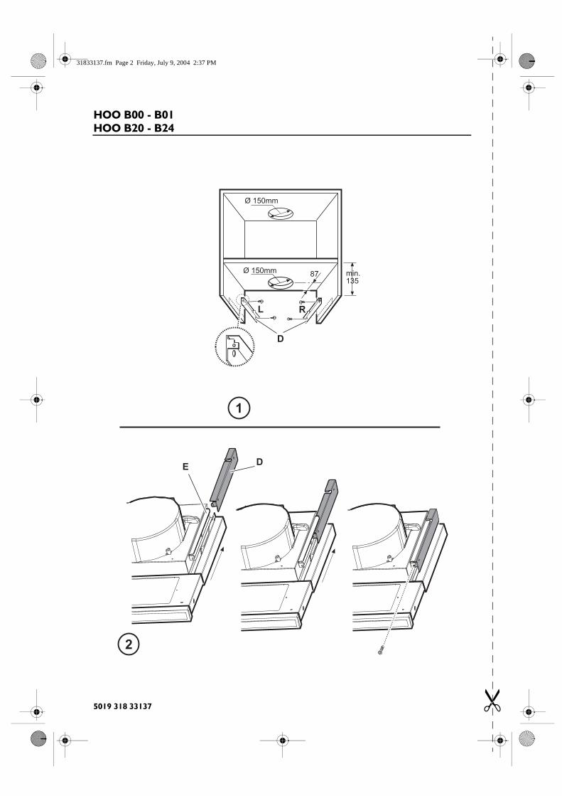
Preliminary information for installing the hood:Do not connect the hood to the power supply during the installation phase.Warning! The 2 fixing brackets are packed with polystyrene protection. There is a right R and a left L bracket (see bracket punching).
1. Fix brackets D (Fig. 1) to the sides of the wall unit using two screws per bracket (right bracket R on the right, left bracket L on the left); the brackets must be parallel with the lower edge of the unit.Position the support bracket so that it is against the back of the wall unit, making sure that the rear edge of the bracket matches the back of the hood.Drill an opening at the top of the wall unit for the exhaust pipe and the power supply cable.
2. Fit the hood inside the wall unit, being careful to position the hood bracket E above the wall unit bracket D (Fig. 1-2).Insert the power supply cable through the opening made for the purpose.
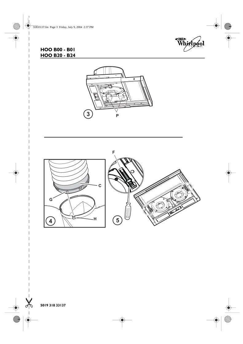
3. Secure the hood with two screws in front (Fig. 2 - one each side).4. Carry out the electrical connection to the mains power supply, only turn on the power supply with assembly completed.5. If necessary, adjust the alignment by loosening the screws P of the brackets E mounted on the hood (Fig. 3) until the
hood and the lower edge of the wall unit line up perfectly, then tighten the screws again.6. Adjust the deflector slideout stroke according to the depth of the wall unit by adjusting the two retainers F (Fig. 5). In
this way the front will be perfectly aligned with the wall unit.a. Loosen the screws of the retainers F;b. adjust by moving the retainers backwards or forwards;c. tighten the screws of the retainers.
7. Fix an outlet duct to the collar C supplied. The outlet duct diameter should be the same as that of the collar (Fig. 4). The exhaust pipe must be long enough to vent externally (extractor version) or must reach the top of the wall unit (filter version).
8. Fix the collar C (snap-close) to the top section of the hood discharge.To facilitate installation, the collar has a mark G that must match the specific guide H on the exhaust duct.
9. Complete the installation of the exhaust duct.
Refit the grease filter/s, connect the hood to the power supply and check for correct hood operation.
INSTALLATION - ASSEMBLY INSTRUCTIONS
31833137.fm Page 13 Friday, July 9, 2004 2:37 PM
5019 318 33137 �
HOO B00 - B01HOO B20 - B24
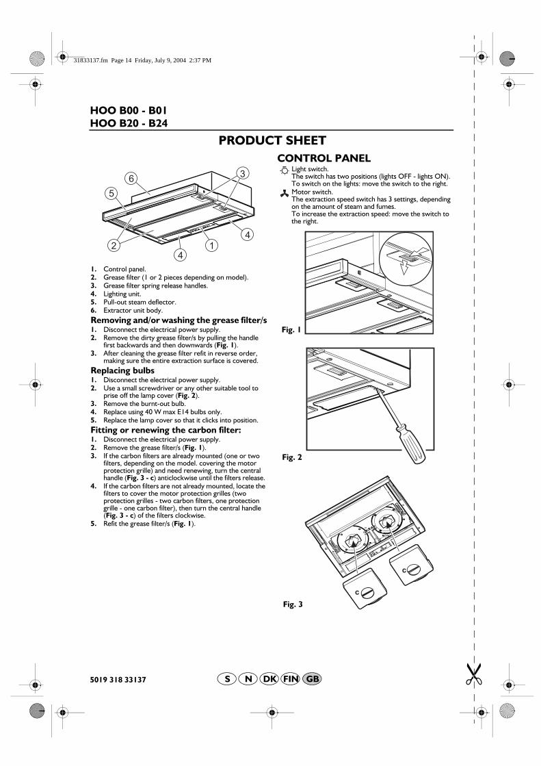
1. Control panel.2. Grease filter (1 or 2 pieces depending on model).3. Grease filter spring release handles.4. Lighting unit.5. Pull-out steam deflector.6. Extractor unit body.Removing and/or washing the grease filter/s1. Disconnect the electrical power supply.2. Remove the dirty grease filter/s by pulling the handle
first backwards and then downwards (Fig. 1).3. After cleaning the grease filter refit in reverse order,
making sure the entire extraction surface is covered.Replacing bulbs1. Disconnect the electrical power supply.2. Use a small screwdriver or any other suitable tool to
prise off the lamp cover (Fig. 2).3. Remove the burnt-out bulb. 4. Replace using 40 W max E14 bulbs only.5. Replace the lamp cover so that it clicks into position.Fitting or renewing the carbon filter:1. Disconnect the electrical power supply.2. Remove the grease filter/s (Fig. 1).3. If the carbon filters are already mounted (one or two
filters, depending on the model. covering the motor protection grille) and need renewing, turn the central handle (Fig. 3 - c) anticlockwise until the filters release.
4. If the carbon filters are not already mounted, locate the filters to cover the motor protection grilles (two protection grilles - two carbon filters, one protection grille - one carbon filter), then turn the central handle (Fig. 3 - c) of the filters clockwise.
5. Refit the grease filter/s (Fig. 1).
CONTROL PANELLight switch.The switch has two positions (lights OFF - lights ON).To switch on the lights: move the switch to the right.Motor switch.The extraction speed switch has 3 settings, depending on the amount of steam and fumes.To increase the extraction speed: move the switch to the right.
Fig. 1
Fig. 2
Fig. 3
PRODUCT SHEET
DK FIN GBNS
31833137.fm Page 14 Friday, July 9, 2004 2:37 PM