honeycomb fiber-reinforced polymer sandwich panels for fish culture tanks
TRANSCRIPT

HONEYCOMB FIBER-REINFORCED POLYMER SANDWICH PANELS FOR FISH CULTURE TANKS
Julio F. Davalos, WVU, Morgantown, WV Justin Robinson, WVU, Morgantown, WV
Avinash Vantaram, WVU, Morgantown, WV Roger C. Viadero, WVU, Morgantown, WV Kenneth Semmens, WVU, Morgantown, WV
Jerry D. Plunkett, Kansas Structural Composites, Inc.
Abstract The U.S. aquaculture gross revenues have grown from $350 million in 1985 to nearly $900 million in 1996, and while large overseas markets are available for native products, the national aquaculture production was only about 3 percent of world production value. It is argued that the utilization of impaired mine waters abundant in WV and the other mid-Appalachian states for fish culture can substantially increase aquaculture economic development. Approximately 232 million gallons of water per day are discharged in WV from both active and abandoned mines, and if only 30% of these water resources were used for aquaculture, the expansion of this industry in West Virginia would be significant. The primary limitation to the effective utilization of discharged waters is the lack of suitable fish culture tanks that can be easily installed in rugged terrains surrounding mine water treatment plants. Such topographical constraints do not easily permit the construction of cast-in-place concrete tanks, and therefore, FRP sandwich materials offer an economical alternative for production of modular, transportable, light, and durable fish culture raceway systems. This study is concerned with the development and evaluation of prototype fish culture tanks using a honeycomb FRP sandwich panel with sinusoidal core geometry, which is produced by KSCI by the contact-molding process. Based on defined functional requirements, a raceway system consisting of four staggered tanks is designed, and each tank is 6x30x3 feet, with a middle partition along the 30-foot length to carry out parallel aquaculture studies. Representative panel samples of the side and bottom walls as well as the side-to-bottom panel connections are tested within the linear range and eventually to failure. The linear response of the samples is analyzed by the finite element method. Keywords: Honeycomb FRP sandwich panel, Fish tank, Finite element modeling
Significance
Aquaculture, the science of growing aquatic plants and animals, continues to develop worldwide
at a rapid pace. In West Virginia, coldwater species like rainbow trout dominate commercial production, with a potential estimated output of four to six million pounds annually (Jenkins et al. 1995). At present, the authors are working with a multidisciplinary group of investigators at WVU to guide and enhance the fish production market in WV under the Aquaculture Food and Marketing Development Project (AFMDP), funded through the USDA. Two focus areas for aquaculture economic development have been identified: (1) production of fish utilizing water discharged from abandoned and active coalmines, and (2) production of farm-raised fish for recreational and tourism purposes. Most commercial trout producers utilize raceways as a culture unit. In these systems water flows through a
1

series of long rectangular tanks usually made of concrete. Fish in these raceways swim against the current much as they would in a stream, and are fed complete rations in pellet form.
Of major significance is the effective treatment and subsequent use of impaired mine waters for fish production in WV, where it is estimated that 232 million gallons of water per day are discharged from both active and abandoned mines, and if only 30% of these water resources were used for aquaculture, the expansion of this industry in WV is expected to increase dramatically. However, the primary limitation for the effective utilization of discharged waters is the lack of suitable fish culture tanks that can be easily installed in rugged terrains surrounding mine water treatment plants. Such topographical constraints do not easily permit the construction of cast-in-place concrete tanks, and therefore, advanced composite materials offer an economical alternative for production of modular, transportable, light, and durable fish culture raceway systems.
Our overall research work on fiber-reinforced polymers (FRP) is directed to the worldwide interest in development and application of new materials and methods for rehabilitation and new construction of industrial and public works, more commonly termed civil infrastructure. Focusing on innovation, we recently obtained funding from the NSF Partnerships for Innovation Program (NSF-PFI). Working with the University of Akron, OH, and Kansas Structural Composites Inc. (KSSCI) as our industrial partner, who will establish a composites manufacturing plant in West Virginia, and in collaboration with other state and federal agencies and associations, this partnership will develop and manufacture novel honeycomb fiber-reinforced polymer (HFRP) sandwich composite materials for applications in construction and aquaculture industries, with emphasis on the development of prototype products, particularly highway bridge decks and modular fish culture tanks. Thus, the fundamental research described in this paper is being funded by the NSF-PFI, while the field implementation of the product is being supported by the USDA-AFMDP.
We present in this paper the development of a fish-culture raceway system (Fig. 1) manufactured from honeycomb FRP panels, 2 to 4 inches thick, using E-glass fibers and a polymer resin (Davalos et al. 2001). The core consists of sinusoidal corrugations and vertical components sandwiched between the face sheets (see Fig. 2), with smooth finished exposed faces that will permit easy cleaning and virtually eliminate algae growth. A dark green pigment will be selected and added to the resin to achieve a permanent color that will not require painting over the service-life of the structure. Also, the resin will be formulated to have a UV resistance for outdoor applications of over 30 years. The resin used will resist nearly any chemical exposure and wet-dry cyclic environments at low and high temperatures, making the honeycomb panels highly durable. The raceway system will consist of four 30 ft by 6 ft tanks staggered vertically to permit gravity flow of water. Each of the 6-foot wide tanks will have a longitudinal partition panel to allow for parallel fish culture studies (Fig. 1). The weight of the panels will be approximately 4 to 6 lb/ft2, which is about 12 times less than the weight of a comparable concrete material. Thus, the HFRP tanks can be easily transported and installed.
Objective And Scope
This study is concerned with the design, manufacturing, and experimental and numerical
evaluations of HFRP sandwich panels and panel-to-panel connections for applications in the forthcoming development and implementation of fish culture tanks, to be installed as raceway systems in West Virginia for fish growth utilizing both treated coalmine waters and fresh spring waters. The component panels are tested as beams and their measured displacements and strains are correlated with finite element analyses with ABAQUS (1998). Similarly, two designs of side-to-bottom panel connections are evaluated experimentally and modeled as cantilever beams to study their relative rotational stiffness of the connected joints. General details of the design of the fish tank are presented, and an overview of three future projects is given.
2
Design Of HFRP Raceway
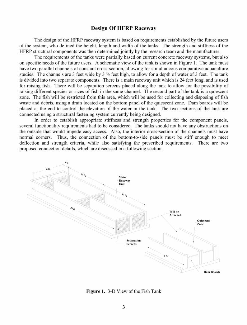
The design of the HFRP raceway system is based on requirements established by the future users
of the system, who defined the height, length and width of the tanks. The strength and stiffness of the HFRP structural components was then determined jointly by the research team and the manufacturer.
The requirements of the tanks were partially based on current concrete raceway systems, but also on specific needs of the future users. A schematic view of the tank is shown in Figure 1. The tank must have two parallel channels of constant cross-section, allowing for simultaneous comparative aquaculture studies. The channels are 3 feet wide by 3 ½ feet high, to allow for a depth of water of 3 feet. The tank is divided into two separate components. There is a main raceway unit which is 24 feet long, and is used for raising fish. There will be separation screens placed along the tank to allow for the possibility of raising different species or sizes of fish in the same channel. The second part of the tank is a quiescent zone. The fish will be restricted from this area, which will be used for collecting and disposing of fish waste and debris, using a drain located on the bottom panel of the quiescent zone. Dam boards will be placed at the end to control the elevation of the water in the tank. The two sections of the tank are connected using a structural fastening system currently being designed.
In order to establish appropriate stiffness and strength properties for the component panels, several functionality requirements had to be considered. The tanks should not have any obstructions on the outside that would impede easy access. Also, the interior cross-section of the channels must have normal corners. Thus, the connection of the bottom-to-side panels must be stiff enough to meet deflection and strength criteria, while also satisfying the prescribed requirements. There are two proposed connection details, which are discussed in a following section.
11 ft.
MainRaceway Unit
6 ft.
24 ft.
2 ft.
11 ft.
Will beAttached
6 ft.
SeparationScreens
Dam Boards
QuiescentZone
Figure 1. 3-D View of the Fish Tank
3

After the initial design of the raceway tank, the required structural capacity of the panels could be determined. Based on past experience, the research team and the manufacturer determined an appropriate size and lay-up. The loads were based on 3 feet of water pressure and other loads possibly from people leaning against the side panels. The deflection limit is based on the separation screen openings, which was determined to be 3/8 of an inch.
A 3-D view of the sandwich panel geometry is given in Figure 2, showing the top and bottom face sheets and the core consisting of sinusoidal and straight components. The constituent materials are chopped E-glass fibers and polyester resin. The side panels have a thickness of 2 inches with the top and bottom face sheets consisting of three layers of chopped strand mat (ChSM), each being 0.03 inches thick. The core is produced from two layers of ChSM. The bottom panels have the same face sheet and core thickness and same materials, but the panel thickness is 4 inches.
Longitudinal Direction
Transverse Direction
Figure 2. Core Geometry of HFRP Panel
Evaluation Of Components
The structural components of the HFRP raceway system consist of the side and bottom panels and their connection. The sinusoidal core orientation is in the “longitudinal direction” (see Figure 2) along the length of the tank. Beam samples representing these panels are experimentally tested to evaluate deflections and strains and to correlate results with finite element analyses. Also, two proposed side-to-bottom panel connections are tested and analyzed by the finite element method. Experimental Testing of Beam Samples
The beam samples used in the experimental protocol consist of five bottom panel samples and five side panel samples. For both panels, there are two longitudinal (sinusoidal wave along the length) and two transverse (sinusoidal wave along the width) samples, each 8-inch wide by five-feet long. In
4

addition, there are two 12-inch wide by about 7-foot long panels, one with transverse core orientation for the side panel and one with longitudinal core orientation for the bottom panel.
The beams are tested in a 3-point loading configuration, and the span-length depends on the overall length of the sample. Strains are measured on the top and bottom face sheets of the sample. On the top, there are three gages spaced equally across the width at a distance of six inches from the midspan. The bottom face sheet is instrumented with one strain gage at the midspan and mid-width of the beam. Deflections are measured at the midspan and at third points with respect to the span-length. The beams are loaded to approximately 300 pounds, staying well within their linear range.
Data is recorded by a computerized data acquisition system and later reduced using a spreadsheet. The data presented in Table 1 are obtained from the linear regression recorded for each sensor for a maximum load of 100 pounds. The reported deflection values for L/3 are the averages of the symmetric values at L/3 and 2L/3. The maximum and minimum strains, as well as the average of the three values, are shown for the top face sheet. Finite Element Analysis of Beam Samples
Finite element beam models are created to correlate predictions with the experimental results. These models are intended to simulate the actual geometry of the beam samples. The beam models are created using 3- and 4-node layered shell element with ABAQUS (1998). The face sheets are composed of three layers of quasi-isotropic chopped strand mat and the core walls are composed of two layers of the same material. Using the pre- and post-processor FEMAP (1999) program, the models are generated using a copy-and-paste method, in which a 4” by 4” “cell” of the specific panel is defined and copied to produce a beam of any length, width and core orientation. Symmetry is exploited to decrease the computational effort, by defining a shear-release boundary condition at the midspan of the models, and the load is applied along the width as a line load. Further details on finite element modeling are discussed in Davalos et al. (2001), Robinson et al. (2001) and Robinson et al. (2002). Table 2 shows the results for 100 pounds of load. The strain data is found by examining the element average values across the width at the desired location with respect to the midspan. Because of the coarseness of the mesh, strain data varies somewhat. Thus, the maximum and minimum strain values are reported, along with the average of the two. The strain results are given in microstrain, while deflections are given in inches. Comparison of Results for Beam Samples
A comparison of experimental and finite element analysis results shows good correlations in strains and displacements. The finite element models show stiffer behaviors than in actuality, predicting lower strains and deflections than recorded in the experimental tests. However, for the cases of longer span-lengths with samples of 12” width, particularly the side panels with transverse core orientation, the predicted deflections are much closer to the experimental values. An observation of the results indicate that both deflections and strains can be predicted by the finite element method with reasonable confidence, and based on these favorable results, the side-to-bottom panel connection is studied in the next section.
5

Table 1. Experimental Results for Beam Samples
Panel Type
Core Orientation
Width, inches
Span, feet
Sample Number Deflection, in Strain, microstrain
@ L/3 @ L/2 Bottom Top Max. Min. Avg.
12" 6' 1 0.0214 0.0246 106 -67 -110 -90 8" 4' 1 0.0118 0.0138 119 -102 -107 -105 Longitudinal 2 0.0120 0.0138 115 -98 -105 -101
8" 4' 1 0.0144 0.0164 128 -102 -123 -112 Bottom
Transverse 2 0.0213* 0.0240* 122 -111 -122 -116
8" 4' 1 0.0513 0.0584 --- -226 -249 -238 Longitudinal 2 0.0513 0.0598 255 -215 -257 -236
12" 5.5' 1 0.0709 0.0866 268 -228 -269 -249 8" 4' 1 0.0531 0.0635 296 -239 -254 -244
Side Transverse
2 0.0534 0.0656 326 -231 -286 -256 *These higher values are being questioned and re-examined.
Table 2. Finite Element Results
Panel Type
Core Orientation
Width, inches
Span, feet Deflection, in Strain, microstrain
@ L/3 @ L/2 Bottom Top Max. Min. Avg. Max. Min. Avg.
12" 6' 0.0196 0.0232 103 73 88 -63 -91 -77 Longitudinal
8" 4' 0.009 0.0108 96 67 82 -57 -81 -69 Bottom
Transverse 8" 4' 0.011 0.0134 128 109 119 -87 -103 -95
Longitudinal 8" 4' 0.0408 0.048 227 172 200 -148 -191 -170
12" 5.5' 0.0708 0.086 217 197 207 -195 -212 -204 Side Transverse
8" 4' 0.045 0.0533 278 222 250 -210 -235 -222
Experimental Testing of the Connection
Two different designs for the connection of the side panel to the bottom panel were proposed, and samples for each connection type were produced and tested. The goal of the experimental testing is to evaluate the two connections and suggest the best design for production of the tank. The unstiffened connection, shown in Figure 3, is designed for the side panel to be embedded into the bottom panel a distance of one inch. The panels are then joined with a polyester resin. The bottom panel extends four inches beyond the outside face of the side panel to allow for a better distribution of stresses at the corner. The stiffened connection, shown in Figure 4, is similar to the previous connection, with the exception of a triangular stiffener placed on the outside edge of the embedded panels. The stiffener, which extends four inches up the side wall and four inches out to the edge of the bottom panel, is produced by a core section of triangular cross-section covered by a face sheet. The stiffener is co-cured to the side and bottom panels. In both cases, the inside corner remains normal as required by the design. Each of the two connection samples is 12 inches wide. The bottom panel extends 18 inches from the interior edge of the side panel, with the longitudinal core orientation along its length. The side panel extends 42 inches from the top of the bottom panel, with the longitudinal core orientation along its length.
6

The experimental testing of the connection is performed by mounting the bottom panel of the sample to a fixed steel vertical column. A tip load is applied to the side panel at a distance of 36-inches from the interior face of the bottom panel, as shown in Figure 5, and deflections are recorded at distances of 24- and 36-inches. Strains are measured at 11 locations on each of the samples, with 5 gages bonded to the bottom panel (#1, #2, #3, #6 and #7), which is fixed to the steel column, and 6 gages bonded to the side panel (#4, #5, #8, #9, #10 and #11). Each gage is bonded in the same respective location for each sample to allow for easy comparisons. The exception being gages #8 and #9 for the stiffened sample, which are offset a distance of 2-inches because of the location of the stiffener. The data is reduced using the same method as for the beam samples, and the strains and deflections for 100 pounds of loading are shown in tables 3 and 4, respectively.
Figure 3. Unstiffened Connection Design Figure 4. Stiffened Connection Design
7

Figure 5. Experimental Setup for Connection
Finite Element Modeling of the Connection
A finite element model of the side panel was conceived as a 12-inch wide by 36-inch long cantilever beam, which assumes complete fixity at the location of the bottom-to-side panel. This simplified boundary condition is used as a baseline to evaluate, by comparison, the relative rotational stiffness of the connection, for both types of connection design. The core geometry of the model corresponds to the actual sample, with the longitudinal core orientation along the length. The beam model is fixed at one end, and a tip line load is applied at the opposite end. The magnitude of the resulting load is 100 pounds. The strains and deflections are shown in tables 3 and 4, respectively, corresponding to the same locations as in the experiment. The predicted strain values are obtained using the same procedure as for the 3-point bending beam models. For gages #8 and #9, the two strain values given in Table 3 correspond to locations on the unstiffened and stiffened panels, as noted in the table. Figure 6 shows the deformed shape of the cantilever beam model.
8
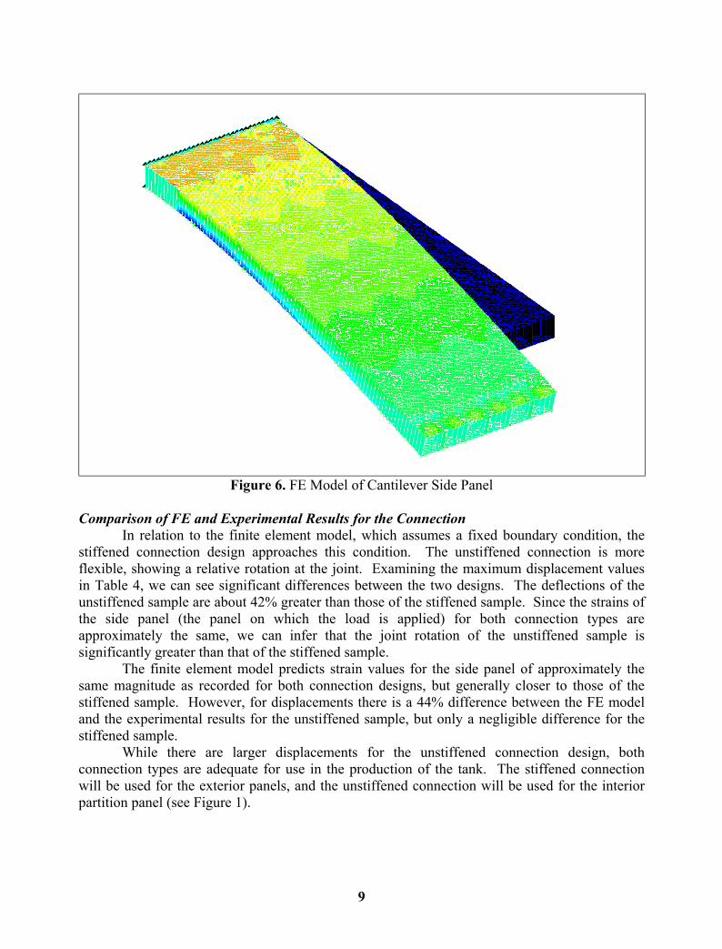
Figure 6. FE Model of Cantilever Side Panel
Comparison of FE and Experimental Results for the Connection
In relation to the finite element model, which assumes a fixed boundary condition, the stiffened connection design approaches this condition. The unstiffened connection is more flexible, showing a relative rotation at the joint. Examining the maximum displacement values in Table 4, we can see significant differences between the two designs. The deflections of the unstiffened sample are about 42% greater than those of the stiffened sample. Since the strains of the side panel (the panel on which the load is applied) for both connection types are approximately the same, we can infer that the joint rotation of the unstiffened sample is significantly greater than that of the stiffened sample.
The finite element model predicts strain values for the side panel of approximately the same magnitude as recorded for both connection designs, but generally closer to those of the stiffened sample. However, for displacements there is a 44% difference between the FE model and the experimental results for the unstiffened sample, but only a negligible difference for the stiffened sample. While there are larger displacements for the unstiffened connection design, both connection types are adequate for use in the production of the tank. The stiffened connection will be used for the exterior panels, and the unstiffened connection will be used for the interior partition panel (see Figure 1).
9

Table 3. Strain Comparisons
Connection Strain Locations, microstrain Sample #1 #2 #3 #4a #5a #6 #7 #8a #9a #10a #11a
Unstiffened 83 180 165 416 388 -15 18 -406 -417 --- -51
Stiffened 42 --- 91 428 433 -196 -173 -366 -392 -222 -61
FE Modelb --- --- --- 394 394 --- --- -407c,
-366d
-407c,
-366d -219 -73
a Gages on the side panel, which is the one loaded. b Values obtained for clamped boundary condition (closer to stiffened connection). c Value corresponds to location for unstiffened sample. d Value corresponds to location for stiffened sample.
Table 4. Deflection Comparisons
Connection Sample
Deflection Location, inch
@ 24" @ 36" Unstiffened 0.1767 0.3027
Stiffened 0.1223 0.2134
FE Model 0.109 0.21
Overview Of Future Installation And Evaluation Of HFRP Raceway Systems
There are two projects currently underway in which modular Honeycomb FRP tanks will
be installed. One site is located at the Dogwood Lakes water treatment facility near Morgantown, West Virginia, which is owned by Consolidated Coal Company. The other site is Reymann Memorial Farm in Wardensville, West Virginia, a university-run research facility. While the terrain and water source at these two sites are different, they both share the need for a removable raceway system.
Dogwood Lakes is a water treatment facility, in which treated mine water is channeled to a settling pond from which the water discharges into a stream. The goal of the aquaculture project at this site is to capture the water from the outlet of the pond, and divert it into a raceway system consisting of four HFRP tanks, which will be staggered along the hillside to grow trout and study the commercial feasibility of treated mine water for fish production. The terrain at Dogwood Lakes is very rugged, making it nearly impossible to use conventional concrete tanks. Moreover, the coal company will not allow permanent structures to be built at this site.
The second site is the Reymann Memorial Farm, owned by West Virginia University. The tanks will be located on a pasture field below a permanent spring of abundant fresh water.
10
Part of the spring water would flow through a 4-tank raceway system and empty into either a pond or an adjacent creek. While the terrain at this site has a gentle slope, the modular HFRP raceway system is preferred because of its mobility and versatility.
In addition to these two sites, there is a third project in which a HFRP tank will be used as an in-pond floating system. The tank will be submerged in a pond and will be fitted with adjustable ballast to permit the tank to float above the water level, which is needed to safely keep the fish inside the tank and to dispose of the fish waste without contaminating the pond. This floating unit will be installed at the Warwick Mine Water Treatment Plant in Greene County, Pennsylvania.
Concluding Remarks
This paper presents an overview of the design of a fish raceway system, consisting of several tanks in series manufactured from honeycomb fiber-reinforced polymer (HFRP) sandwich panels. The design is based on functionality requirements, and accordingly, structural members are sized and corresponding samples are manufactured and experimentally tested to evaluate their linear response, which is also investigated using finite element models with ABAQUS (1998).
Several projects utilizing this new product have been planned and started. Thus, it is expected that demand for the HFRP tanks will increase. Future field evaluations by the research team and users of the raceway system will define further refinements to the overall design of the individual tanks. Furthermore, additional experimental testing will be performed, including failure of the samples discussed in this paper. A finite element analysis of the entire tank, based on equivalent panel properties, will be conducted to assist in the optimization of the structural components and connections.
11

References 1. ABAQUS, Standard Users Manual, 1998, version 5.8. Hibbitt, Karlsson and Sorensen,
Inc., USA 2. Davalos, J.F., Qiao, P.Z., Xu, X.F., Robinson, J. and Barth, K.E. 2001. “Modeling and
characterization of fiber-reinforced plastic honeycomb sandwich panels for highway bridge applications,” J. Comp. Struct. 52(2001): 441-452.
3. FEMAP Users Manual, 1999, version 8.0. Enterprise Software Products, Inc., Exton, PA. 4. Jenkins, M.R., Wade, E.M., Fletcher, J.J., and Hankins, J.A. 1995. “Economic analysis
of non-traditional water resources for aquaculture in West Virginia.” The Conservation Fund’s Freshwater Institute, Shepherdstown, WV.
5. Robinson, J., Davalos, J.F., Xu, X.F., Qiao, P.Z., and Barth, K.E. 2001. “FRP honeycomb composite sandwich beams under bending,” Proceedings of the ASC 16th Annual Technical Conference, American Society of Composites (ASC), Blacksburg, VA, Sept. 9-12 (in CD-ROM, Paper#111, 12 pages).
6. Robinson, J., Davalos, J.F. and Qiao, P.Z., 2002. “Modeling and characterization of FRP honeycomb composite sandwich beams,” Proceedings of the 3rd International Conference on Composites in Infrastructure (ICCI’02), San Francisco, CA, June 10-12 (In press).
12