homeplug 1.0 mac
DESCRIPTION
(c) 2013 R. Newman University of Florida. HomePlug 1.0 MAC. What is HomePlug 1.0?. Broadband PLC for home networking Open industry standard 4 manufacturers (including Intellon) Developed in 2000 by Homeplug Powerline Alliance (HPA) Consortium of chip designers, OEMs, PLC users - PowerPoint PPT PresentationTRANSCRIPT

HomePlug 1.0 MAC
(c) 2013 R. NewmanUniversity of Florida

What is HomePlug 1.0?• Broadband PLC for home networking• Open industry standard
– 4 manufacturers (including Intellon)• Developed in 2000 by Homeplug Powerline
Alliance (HPA)– Consortium of chip designers, OEMs, PLC users– Products shipped in 2001
• First ethernet class PLC, most widely available– 11 Mbps coded PHY data rate– 0ver 10 million units shipped
• Comprises– PHY – modulation, coupling, FEC, etc.– MAC – medium access, ARQ, etc.– Bridging – to other PLC networks or to 803.3/11/etc.

HomePlug 1.0 MAC Overview• Frame Transport
• Frame length = 46-1500 bytes/frame• IEEE 802.3 frames encapsulated• IEEE 802.3 48-bit addressing used• Bridging between PLC and other networks
• Reliable Frame Delivery• Rate adaptive PHY• Channel estimation and tone map generation• Stop&Wait ARQ for unicast frames• “Partial ACK” for multicast frames• Segmentation to limit time exposed on wire

HP 1.0 MAC Overview (con’t)• Quality of Service
• 4 priority levels for differentiated service• Priority signaling slots enforce priority access• Segmentation bounds delay• Bursting for contention-free access
• Privacy• 56-bit key DES encryption in CBC mode• Password-based key derivation supported
• Management• Registered ethertype for management data

HP1.0 MAC• CSMA/CA• Virtual Carrier Sense - length in FC• 4 levels of priority for differentiated service• Advanced contention resolution• Variable tone map, including code rate selection• Packets of ~0.5ms to ~2ms• Packet bursting to avoid contention• Stop&Wait ARQ• 56-bit DES in CBC mode for privacy• Bridging function

HP1.0 PHY PDU• Preamble = 38.4 usec
• Set pattern of 7.5 special symbols• Allows AGI, synchronization by receiver• Detection used for PCS
• Frame Control (FC) = 33.6 usec. (4 symbols)• Heavily coded • Uses BPSK (low rate) modulation• Very robust• Very few (25) information bits
• FC holds info for PHY• Tone Map Index- for demodulation of body• Frame duration (how long to demodulate)

HP1.0 PHY Frame Format
• Detect delimiter from preamble, correct FC• SOF FC indicates symbol count, tone map• Pad Frame Body to PHY Tx block boundary• EOF FC delimits end of data frame
Preamble FrameControl
FrameHeader
FrameBody PAD FCS Preamble Frame
Control
RIFS
Preamble FrameControl
25 bits 17 bytes Variable ByteCount
2 bytes 25 bits 25 bits
4 OFDMsymbol
4 OFDMsymbol
Start of frame delimeter( uses all tones)
Frameheader
Framebody
and padCheck
sequenceEnd of frame delimeter
( uses all tones)
Responsedelimeter
( uses all tones)
4 OFDMsymbol
Variable symbol count20 - 160 OFDM symbols
FC indicatesmodulationand length
EFG

HP1.0 Delimiters• Delimiter
• Preamble + frame control = 72.0 usec• FC holds 25 bits of information
• 1 bit – contention control (CC)• 3 bits – delimiter type (DT)• 13 bits – variant field (depends on DT)• 8 bits – frame control check sequence (FCCS)
• CC bit restricts next access• If set, only frames at same or higher priority
allowed to contend• FCCS checks frame control
• 8-bit CRC G ( x )=x8 +x 2+x+ 1

HP1.0 Delimiter Type• 000 = SOF, no response expected (mcast/bcast)• 001 = SOF, response expected• 010 = EOF, no response expected• 011 = EOF, response expected• 100 = ACK (frame received w/o errors)• 101 = NACK/FAIL
• Variable field has Response Type (RT)• RT=0 – NACK if address recognized but errors• RT=1 – FAIL if frame error-free but receiver
does not currently have resources to receive• 110-111 = Reserved
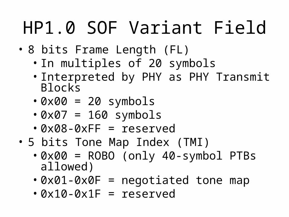
HP1.0 SOF Variant Field• 8 bits Frame Length (FL)
• In multiples of 20 symbols• Interpreted by PHY as PHY Transmit Blocks• 0x00 = 20 symbols• 0x07 = 160 symbols• 0x08-0xFF = reserved
• 5 bits Tone Map Index (TMI)• 0x00 = ROBO (only 40-symbol PTBs allowed)• 0x01-0x0F = negotiated tone map• 0x10-0x1F = reserved

HP1.0 EOF Variant Field• 2 bits Channel Access Priority (CAP)
• 11 = highest, 00 = lowest• Used for bursting
• 1 bit Invalid• Must be set to 0 or FC is invalid
• 10 bits Reserved• Set to 0 on transmit, ignored on receive
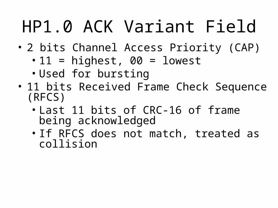
HP1.0 ACK Variant Field• 2 bits Channel Access Priority (CAP)
• 11 = highest, 00 = lowest• Used for bursting
• 11 bits Received Frame Check Sequence (RFCS)• Last 11 bits of CRC-16 of frame being
acknowledged• If RFCS does not match, treated as collision
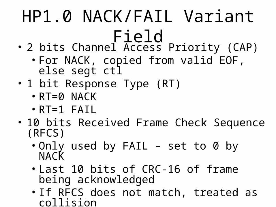
HP1.0 NACK/FAIL Variant Field• 2 bits Channel Access Priority (CAP)
• For NACK, copied from valid EOF, else segt ctl• 1 bit Response Type (RT)
• RT=0 NACK• RT=1 FAIL
• 10 bits Received Frame Check Sequence (RFCS)• Only used by FAIL – set to 0 by NACK• Last 10 bits of CRC-16 of frame being
acknowledged• If RFCS does not match, treated as collision
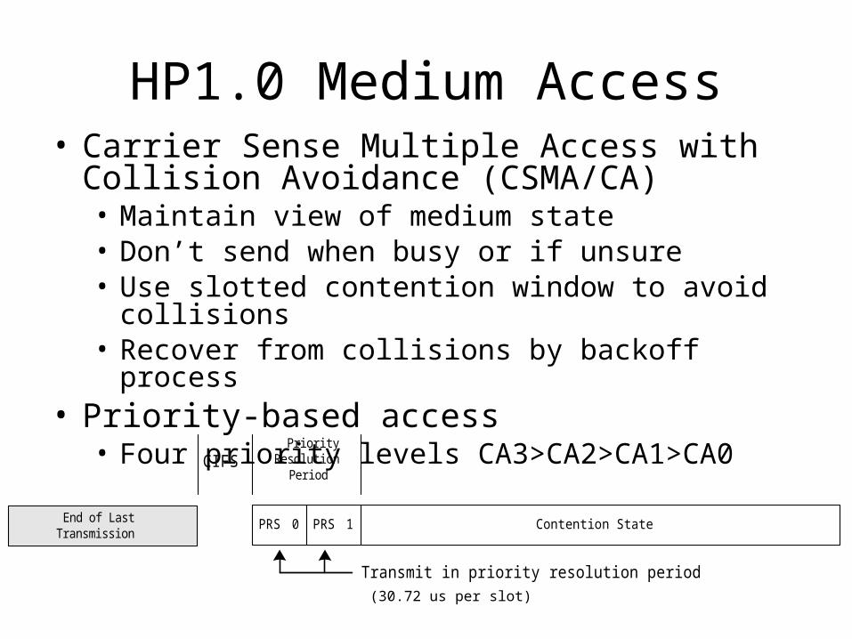
HP1.0 Medium Access• Carrier Sense Multiple Access with Collision
Avoidance (CSMA/CA)• Maintain view of medium state• Don’t send when busy or if unsure• Use slotted contention window to avoid collisions• Recover from collisions by backoff process
• Priority-based access• Four priority levels CA3>CA2>CA1>CA0
End of LastTransmission
CIFS
Contention State
PriorityResolution
Period
PRS 0 PRS 1
Transmit in priority resolution period(30.72 us per slot)

HP1.0 CSMA/CA
Medium states when frame sent or detected during contention
Fram e T ransm ission PR S0 PR S1 Backo ff F ram e T ransm ission
Busy PR S0 PR S1 C ontention S ta te Busy
M ed ium S ta te
A c tiv ity on the M ed ium
• Carrier Sense• PCS by SYNC detection (SOF, EOF, ACK,
NACK/FAIL)• VCS by delimiter type and fields

HP1.0 CSMA/CA (con’t)
Medium states when preempted in PRSs but no frame detected
• Priority Slots (PRSs)• Two slots (PRS0, PRS1), 30.72 usec per slot• Assert “1” bits in CAP – shortened inverted preamble• Receive others’ “ORed” bits if “assert” 0 in a PRS• Defer if “1” detected
Frame Transmission PRS0 PRS1 Defer to higher priority
Busy PRS0 PRS1 Contention State Idle
EIFS
Medium State
Activity on the Medium
Backoff

HP1.0 CSMA/CA (con’t)
Medium states when collision detected but no frame detected
• Collisions• Inferred from absence of expected response or Frame
Control errors
Busy Id le
EIFS
Fram e C ontro l E rrorsor
C ollis ion
F ram e T ransm ission
Busy
A ctiv ity on the M ed ium
M ed ium S ta te
Backoff

HP1.0 Interframe Space (IFS)• End of Frame Gap (EFG)
• 1.5 usec between end of frame body and EOF• Contention IFS (CIFS)
• 35.9usec between end of last transmission and PRS0• Response IFS (RIFS)
• 26.0usec between end of a transmission and start of its expected response (ACK, NACK/FAIL)
• Delimiter indicates whether response is expected• If none expected, CIFS is used
• Extended IFS (EIFS)• Used when station is unsure of medium state• Maximum busy time possible• EIFS = 3*delim + EFG + 2*PRS + CIFS + RIFS +
Max frame size * symbol time

HP1.0 CIFS and RIFS
Delim iter Typeindicates no responseexpected
End of LastTransm ission
C ontention Interfram e Space (C IFS)
Contention S tate
PriorityResolution
Period
Delim iter Typeindicates responseexpected
End of LastTransm ission
Response (ACK, NACK, FA IL)
Response In terfram e Space (R IFS)
C IF S
next Priority Resolution Period

HP1.0 Collision Avoidance• Priority Resolution
• Only frames of highest priority contend• Priority resolution slots enforce priority strictly
• Contention Period• 35 usec slots to start transmission/detect sync• Initial number of slots depends on priority level• Randomly select a slot in initial contention window• Listen to earlier slots – defer if detect transmission• Resume countdown next available contention period
• Random Backoff• Invoked if collision detected

HP1.0 Random Backoff Procedure• Goal is to estimate number of contenders• Adjust contention window used to minimize time
until successful transmission• Avoid collisions• Avoid extended idle times
• Use information available• Collisions• Deferrals
CA3 & CA2 CA1 & CA0BPC=0 CW=7, DC=0 CW=7, DC=0BPC=1 CW=15, DC=1 CW=15, DC=1BPC=2 CW=15, DC=3 CW=31, DC=3BPC=3 CW=31, DC=15 CW=63, DC=15

HP1.0 Random Backoff ProcedureCounters Used
• BPC – Backoff Procedure Event Counter• TC – Transmit Counter – # times transmitted• BC – Backoff Counter – countdown to Tx• DC – Deferral Counter – # times deferred• CW – Contention Window – range for BC• Collision_Retries – when not in ROBO• NACK_Retries – when not in ROBO• FAIL_Retries• Collision_ROBO_Retries – when in ROBO• NACK_ROBO_Retries – when in ROBO

HP1.0 Random Backoff Procedure1. Initialize counters to 0, go to step 22. Determine medium state– If Idle, transmit– If Busy, wait– If PRS0 or PRS1, resolve priority, go to step 3
3. If priority contention lost, go to step 2

HP1.0 Random Backoff Procedure
1. If priority contention won, then may contend
If BPC=0 or BC=0 or DC=0 • Set CW to CW[BPC,priority]• Set DC to DC[BPC,priority]• Increment BPC• Set BC = Random(CW)• On each contention slot when BC>0,
• If empty, decrement BC • If medium becomes busy, go to step 2
• If BC = 0, transmit, then go to step 5

HP1.0 Random Backoff Procedure1. After transmitting a frame
a. If no response expected, or if receive ACK with valid RFCS, then done.
b. If collision inferred, then increment proper collision counter, and
- If robo retry max reached, discard frame, - else if regular retry max reached, switch to
ROBO,- else try again – go to step 2

HP1.0 Random Backoff Procedure1. After transmitting a frame (con't)
a. If valid NACK received, then increment proper NACK counter, and
Reset BPC to 0- If NACK robo retry max reached, discard
frame, - else if NACK regular retry max reached,
switch to ROBO,- else try again – go to step 2
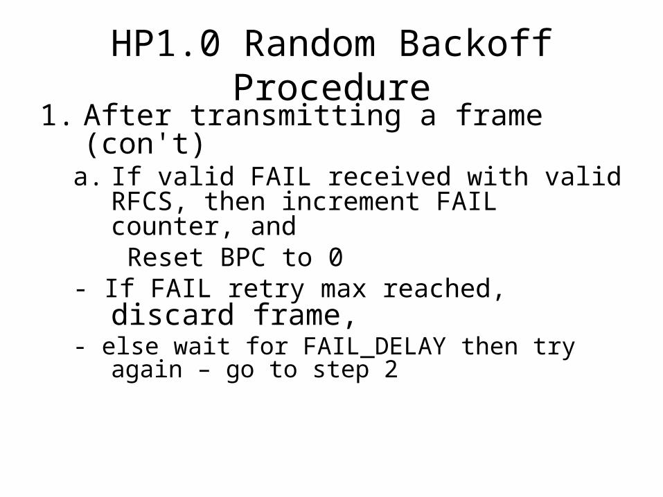
HP1.0 Random Backoff Procedure1. After transmitting a frame (con't)
a. If valid FAIL received with valid RFCS, then increment FAIL counter, and
Reset BPC to 0- If FAIL retry max reached, discard frame, - else wait for FAIL_DELAY then try again – go to
step 2

HP1.0 Random Backoff Procedure
Key points:1. Very conservative in avoiding collisions2. Uses collisions to estimate number of
contenders, like 802.3 and 802.113. Also uses number of deferrals to
estimate number of contenders4. Eschewed the theoretically more efficient
binary countdown approach to use more robust (against confusion) unary approach

HP1.0 MAC Data Frame Format
• Data frame has SOF, payload, EOF • Block pad (B-PAD) zero-fills last PHY Tx Block• Frame Check Sequence (FCS) – 16-bit CRC• EOF followed by end-of-frame gap (EFG)• Immediate response delimiter
S egm en t Contro l Fram e Body FCS
5 bytes variab le byte count 2 bytes
variable sym bol coun t20 -160 sym bols
DA
6 bytes 6 bytes
Fram e Header Check S equence
B-PA DSA
EFG P ream b le Fram e Contro l
25 b its
P ream ble Fram e Contro l
25 b its
4 sym bols
D elim iter
4 sym bols
D elim iter
Fram e C ontro l ind icates
S tart o f Fram eContention Contro lLength o f fram eTone M ap Index
Payload
A dap ted m odula tion and tonesD ecoded based on Tone M apE xtensib le to h igher rates
Fram e C ontro l ind icates
E nd of Fram eC ontention Con tro lC hanne l access priority

HP1.0 Frame Header
• Frame Header is channel adapted• Only intended receiver demodulates it
• 48-bit DA and SA • IEEE 802.3 MAC addresses
• 40-bit Segment Control• Holds length of actual data along with flags,
bursting info, CAP
Segment Control Destination Address Source Address
5 bytes 6 bytes 6 bytes

HP1.0 Segment Control Field• 3 bits Protocol Version Number (=1)• 2 bits reserved• 1 bit Multicast Flag (MCF) (=1 for mcast/bcast)• 2 bits Channel Access Priority (CAP)• 15 bits Segment Length (SL)
• Length in bytes of Frame Body• Not including Segment Header, E-Pad, or ICV
• 1 bit Last Segment Flag (LSF)• Set if last (or only) segment in Service Block
• 6 bits Segment Count (SC)• Incremented with each new segment of a Service Block
• 10 bits Sequence Number (SN)• Incremented with each new Service Block sent

HP1.0 Segmentation
S eg m en t C o n tro l F ra m e B od y 1 F C SD A S AF irs t M P D U
D a taD A S A Type /Le ng th
F ra m eC o n tro l S e gm e n t C on tro l F ra m e B o dy n F C SD A S AL as t M P D U
M S D U
M axim u m L en g th
F ra m eC on tro l
F ra m eC o n tro l
F ram eC on tro l
E n cryp tio n C on tro l M A C M ana gem en t In fo rm a tio nA dd ed M A CIn form a tion
S erv ice B lo ck
F ram e B od y nF ra m e B o dy 1 ...
B -P a d
E -P a d IC V
S e g m en ta tion
V L A N ta g(o p tiona l)

HP1.0 Service Block
• 9 bytes Encryption Control (EC)• 1 byte Encryption Key Select (EKS)• 8 bytes Initialization Vector (IV)
• IV=0 means encryption is bypassed• 4 bytes Integrity Check Value (ICV)
• 32-bit CRC of bytes following Encryption Control through E-PAD before encryption
• EC and ICV are present in every Service Block
EncryptionControl
Type Frame Data ICVMAC ManagementInformation (optional) E-PAD
9 bytes 0-M bytes 2 bytes 0-N bytes 4 bytes
(optionally encrypted)(cleartext)
0-7 bytes
VLAN Tag(optional)
4 bytes

HP1.0 Service Block Fields• 4 Bytes IEEE 802.1Q VLAN Tag (copied from MSDU)
• Present iff present in MSDU frame • Variable length MAC Management Information
• Indicated by ethertype 0x887B in first two bytes• MAC Control byte indicates # MAC data entries • Type/Length/Value (TLV) encoded on MAC Entries
• 2 Bytes Type (copied from data frame) • Present only if Service Block carries MSDU
• Variable length Frame Data (copied from data frame)• Present only if Service Block carries MSDU
• Variable length Encryption Pad (E-PAD)• Pads encrypted bits to a multiple of 64 bits• Present even if encryption is bypassed

HP1.0 MAC Management Entries• Channel estimation request/response
• Tone Map Index (TMI)• Tone map
• bit map of valid tones, FEC rate, Modulation method• Bridged addresses, etc.
• Replace bridge address• Allows reconstruction of original MSDU with SA, DA
• Set/confirm network encryption key• EKS, 64-bit NEK
• Multicast with response• Holds MAC multicast address• DA in Frame Header indicates STA to respond
• Request Parameters and Statistics• Vendor specific
• Start with OUI

HP1.0 MAC Parameters and Statistics
• Transmit Counters• ACK• NACK• FAIL• Contention loss• Collisions• Tx latency counter for all priorities CA0-CA3
• Receive Counters• Bytes per 40-symbol packet
• SNMP Compatible• Stored in MIBs

HP1.0 Tone Maps• Tone Map is stale if
• Expires (30 second lifetime)• Transmitter forced to go to ROBO• New link
• Limits on how often TMs requested• Avoid too much computation at receiver• Avoid too much network traffic
• Request Channel Estimation MME • Always sent using ROBO modulation
• Channel Estimation Response• Within 1 second• Must change the TMI• May be sent unsolicited

HP1.0 Privacy/Key Management• DES using CBC mode (64 bit blocks) • Data encrypted with Network Encryption Key
(NEK)• NEK may be generated from password
• Specifies method: PBKDF1 from PKCS#5v2.0• Valid password is 4-24 printable ASCII chars• EKS = 0x01 in this case
• NEK may be sent to a new STA over network• Set Key MME must be encrypted• “Default key” or password of new STA may be entered
on STA already in network, used to encrypt MME• EKS for Set Key MME is 0x00 in this case

HP1.0 Logical Networks
AC Power Line
Neighbor's LogicalNetwork
Logical NetworkSet by Encryption Key
HomePlugStationTone Map
HomePlugStation
HomePlugStation
HomePlugStation

HP1.0 Field Tests vs. 802.11b• 2700 Sq. ft., 10 year-old residence interior walls hollow (not concrete) two laptop computers with both interfaces
Network Configurationsad hoc networkvery short distances with line of sight modified Infrastructure modeLaptop-2 through the Ethernet to base stationbase station talking to Laptop-1fixed location of base station (and Laptop-2)moved Laptop-1 to various locations

HP1.0 Field Test ScenariosScenario-1: FTP – Transmit Buffer Size: 4096 BytesReceive Buffer Size: 4096 BytesFile transfer size: 40 Mbytes
Scenario-2: TCP – Buffer Length: 4096 BytesNumber of Buffers Sent: 5000Total data exchange: 20 Mbytes

Field Tests Results vs. 802.11bTrans.
LocationReceiverLocation
Tx to Rx Distance
802.11b (Mbps)
802.11b (Mbps)
Powerline (Mbps)
Powerline (Mbps)
WSFTP TTCP WSFTP TTCP
Laptop-1 Laptop-2 2 ft 3.2 4.9 4.2 5.2
Study Room Dinning Room 23 3.6 4.7 4.5 5.3
Home Office Kitchen ~35 2.5 4.1 4.0 4.5
Kitchen Home Office ~35 2.4 1.6 3.1 3.1
Bedroom C Home Office ~70 No Conn. No Conn. 1.9 1.8
Home Office Bedroom C ~70 No Conn. No Conn. 4.1 3.9
Pool Area Home Office ~60 No Conn. No Conn. 2.0 1.6
Home Office Pool Area ~60 No Conn. No Conn. 2.4 2.8