homemade rf step attenuator
TRANSCRIPT

An RF Step Attenuator When you can find a good, commercially made RF attenuator, expect to pay the price. Here’swhere doing it yourself can provide you with what you need inexpensively.
By Denton Bramwell, K7OWJ3139 Royalton Hts RdSt Joseph, MI 49085
If you’re doing any serious receiver home brewing, a good RF step attenuator is one of the key pieces of equipmentthat belongs on your workbench. Good attenuators are hard to find at prices that won’t injure your wallet. If you’re lucky,you may find a used HP-355 series unit at a flea market, but it won’t be cheap! Hams who have them and know theirvalue don’t surrender them easily!
Hams are accustomed to substituting ingenuity for money. That was my approach. The result: a home brew stepattenuator that provides good performance, yet can be built with a few basic tools. 1 This unit is designed for use in 50-Ωline, provides a total attenuation of 71 dB in 1-dB steps, offers respectable accuracy and insertion loss through 225 MHzand can be used at 450 MHz (see Table 1).
DescriptionRefer to Figure 1. The attenuator consists simply of 10 resistive π attenuator sections such as the one shown here.
Each section consists of a DPDT slide switch and three 1/4-W, 1%-tolerance metal-film resistors whose values arechosen to obtain the desired amount of attenuation. The completed unit contains single 1, 2, 3 and 5-dB sections, and six10-dB sections. Table 2 lists the resistor values required for each section.
The enclosure is made of brass sheet stock, readily available at many hardware stores. By selecting the right stock,you can avoid having to bend the metal and perform a minimal amount of cutting.
ConstructionI built the enclosure using only a nibbling tool, a drill press, metal shears and a butane-heated soldering iron. To cut
the rectangular tubing to length, I used my drill press equipped with a small abrasive cutoff wheel. It’s not an elegantsolution, but it’s inexpensive and works well enough.
Brass is easy to work and solder. For the enclosure, you’ll need two precut 2 × 12 × 0.025-inch sheets and two 1 × 12× 0.025-inch sheets. The 2-inch-wide stock is used for the front and back panels; the 1-inch-wide stock is used for theends and sides. For the innards, you need a piece of 5/32 × 5/16-inch rectangular tubing, a 1/4 × 0.032-inch strip, and afew small pieces of 0.005-inch-thick stock to provide interstage shields and form the 50- Ω transmission lines that run fromthe BNC connectors to the switches at the ends of the step attenuator.
For the front panel, nibble or shear a piece of 2-inch-wide brass to a length of about 9-1/2 inches. Space theswitches from each other so that a piece of the rectangular brass tubing lies flat and snugly between them. Drill holes forthe #4-40 mounting screws and nibble or punch rectangular holes for the bodies of the slide switches.
Before mounting any parts, solder in place one of the 1-inch-wide chassis side pieces to make the assembly morerigid. Solder the side piece to the edge of the top plate that faces the “through” side of the switches; this makes laterassembly easier (see Figure 2).
I installed BNC input and output connectors on the top (front) panel, which may not be the best location. You may beable to achieve a little better lead dress and high-frequency performance if you mount the connectors at the ends of theenclosure.
The DPDT slide switches I used are designed for sub-panel mounting. Their mounting holes are tapped for a #4-40
June 1995 QST Volume 79, Number 6
Page 1 - Copyright © 1996 American Radio Relay League, Inc. All rights reserved

screw, so I slightly enlarged the holes to allow a #4-40 screw body to slide through. Before mounting the switches, makethe “through” switch connection (see Figure 1) by bending the two lugs at one end of each switch toward each other andsoldering the lugs together. Or, solder a small strip of brass between the lugs and clip off the lug ends. Mount the switchesabove the front panel, using 5/32-inch-high by 7/32-inch-OD spacers. Use the same size spacer on the inside. On theinside, the spacer creates a small post that helps reduce capacitive coupling from one side of the attenuator to the other.The spacers position the switch so that the 50-Ω stripline can be formed later.
The trick to getting acceptable insertion loss in the “through” position is to make the attenuator look as much aspossible like 50-Ω coax. That’s where the rectangular tubing and the 1/4 × 0.032-inch brass strip come into the picture (seeFigure 3); they form a 50-Ω stripline.
Cut pieces of the rectangular tubing, about 3/4-inch long, and sweat solder them to the front panel between each ofthe slide switches. Next, cut lengths of the 1/4-inch strip long enough to conveniently reach from switch to switch, then cutone more piece. Drill 1/16-inch holes near both ends of all but one of the 1/4-inch strips. The undrilled piece is used as atemporary spacer, so make sure it is flat and deburred.
Lay the temporary spacer on top of the rectangular tubing between the first two switches, then drop one of the drilled1/4-inch pieces over it, with the center switch lugs through the 1/16-inch holes. Before soldering, check the strip to makesure there’s sufficient clearance between the 1/4-inch strip and the switch lugs; trim the corners if necessary. Use ascrewdriver blade to hold the strip flat and solder the lugs to the strip. Remove the temporary spacer. Repeat thisprocedure for all switch sections. When you’re done, you’ll have a 50-Ω stripline running the length of the attenuator.
Next, solder in place the three resistors of each section. Use 1%-tolerance resistors and keep their leads as short aspossible. If you must leave a resistor ground lead longer than you like, use a generous blob of solder to make the lead lessinductive. Install a 1/2-inch-square brass shield between each 10-dB section to ensure that signals don’t couple aroundthe sections at higher frequencies.
Use parallel 1/4-inch strips of 0.005-inch-thick brass spaced 0.033 inch apart to form 50- Ω feed lines from the BNCconnectors to the switch contacts at each end of the stripline (see Figure 4).
Finally, solder in place the remaining enclosure side, cut and solder the end pieces, and solder brass #4-40 nuts tothe inside walls of the case to hold the rear (or bottom) panel. (You may find it easier and sturdier to solder the screws tothe case walls. Ed.) Drill and attach the rear panel and round off the sharp corners to prevent scratching or cuttinganyone or anything. Add stick-on feet and labels, and your step attenuator is ready for use.
SummaryYou’ll find the attenuator a useful tool. Used with a simple broadband detector, 2 it provides a convenient way to make
absolute power measurements up to 250 mW. For antenna gain, F/B and F/S measurements, the attenuator can be usedin line, with the receiver acting as the detector. Calibrated attenuator steps are much more accurate for this purpose thanmost receivers’ S meters. Of course, the attenuator is also useful for performing receiver MDS and two-tonedynamic-range measurements.
Remember: This unit is built with 1/4-W resistors, so it can’t dissipate a lot of power. Remember, too, that for theattenuation to be accurate, the input to the attenuator must be a 50- Ω source and the output line must be terminated in a50-Ω load.
Notes(1) See also Bob Shriner, WA0UZO, and Paul K. Pagel, N1FB, “A Step Attenuator You Can Build,” QST, Sep 1982, pp
11-13. PC-board material cut to size and with switch and jack mounting holes made for the 1982 attenuator enclosure only is available from FAR Circuits, 18N640 Field Ct, Dundee, IL 60118-9269. Price: $8, plus $1.50shipping.
(2) See the sidebar “Measuring Double-Tuned Circuit Performance” on page 31 in Wes Hayward, W7ZOI, “TheDouble-Tuned Circuit: An Experimenter’s Tutorial,” QST, Dec 1991, pp 29-34.
June 1995 QST Volume 79, Number 6
Page 2 - Copyright © 1996 American Radio Relay League, Inc. All rights reserved

Double-Tuned Circuit: An Experimenter’s Tutorial,” QST, Dec 1991, pp 29-34.
The RF step attenuator.
June 1995 QST Volume 79, Number 6
Page 3 - Copyright © 1996 American Radio Relay League, Inc. All rights reserved

Figure 1 Schematic of one section of the attenuator. All resistors are 1/4-W, 1%-tolerance metal-film units. See Table 2.Any attenuation value from 1 to 71 dB, in 1-dB steps, can be selected by using the appropriate combination of switches.Good accuracy is maintained through 225 MHz and even 450 MHz (see Table 1).S1-S10 DPDT slide switch (Digi-Key SW116-ND, Digi-Key Corp, 701 Brooks Ave S, PO Box 677, Thief River Falls, MN56701-0677, tel 800-344-4539, 218-681-6674, fax 218-681-3880); equivalent switches can be substituted.Misc: Brass sheet and rectangular tubing (see text), metal spacers, hardware and input/output connectors.
June 1995 QST Volume 79, Number 6
Page 4 - Copyright © 1996 American Radio Relay League, Inc. All rights reserved

Figure 2 Solder one of the 1-inch-wide chassis side pieces in place to make the assembly more rigid. Solder the sidepiece to the edge of the top plate that faces the “through“ side of the switches; this makes the rest of the assembly easier.
June 1995 QST Volume 79, Number 6
Page 5 - Copyright © 1996 American Radio Relay League, Inc. All rights reserved
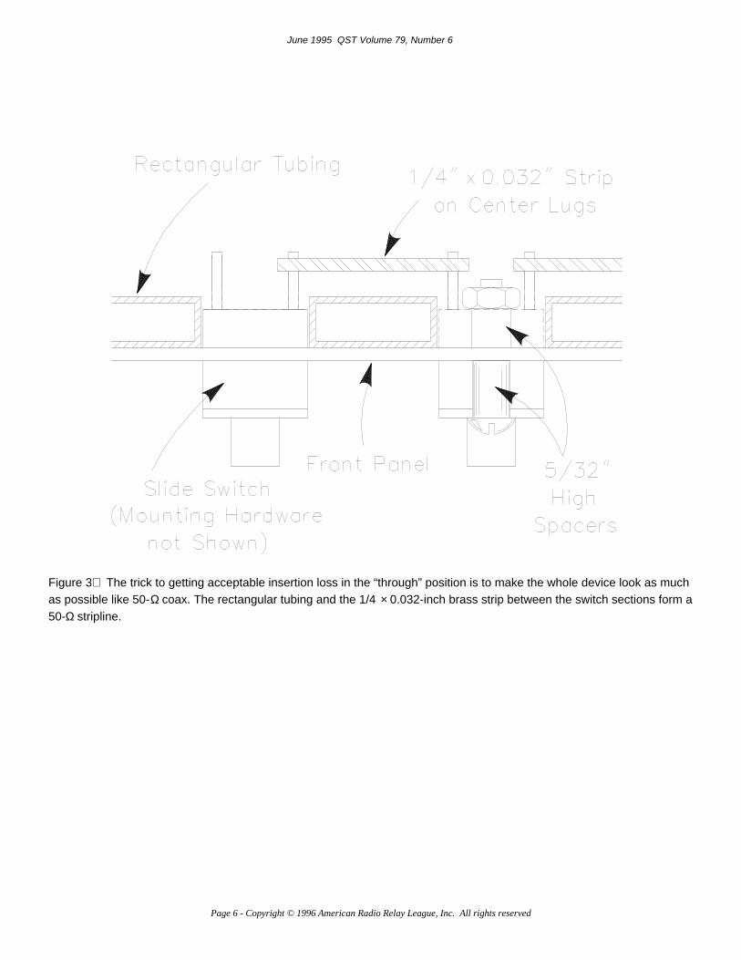
Figure 3 The trick to getting acceptable insertion loss in the “through” position is to make the whole device look as muchas possible like 50-Ω coax. The rectangular tubing and the 1/4 × 0.032-inch brass strip between the switch sections form a50-Ω stripline.
June 1995 QST Volume 79, Number 6
Page 6 - Copyright © 1996 American Radio Relay League, Inc. All rights reserved

Figure 4 The attenuator before final mechanical assembly. The 1/4-inch strips are spaced 0.033 inch apart to form a 50-Ω connection from the BNC connector to the stripline. There are 1/2-inch square shields between 10-dB sections. Thesquare shields have a notch in one corner to accommodate the end of the rectangular tubing.
Table 1
Step Attenuator Performance at 148, 225 and 450 MHz
Attenuator set for maximum attenuation (71 dB)Frequency(MHz)
Attenuation(dB)
148 72.33225 73.17450 75.83
Attenuator set for minimum attenuation (0 dB)
June 1995 QST Volume 79, Number 6
Page 7 - Copyright © 1996 American Radio Relay League, Inc. All rights reserved

Frequency(MHz)
Attenuation(dB)
148 0.4225 0.4450 0.84
Note: Measurements made in the ARRL Laboratory. Laboratory-specified measurement tolerance of ±1 dB.
Table 2
Closest 1%-Tolerance Resistor ValuesAttenuation(dB)
R1 (Ω) R2 (Ω)
1.00 866.00 5.602.00 436.00 11.503.00 294.00 17.405.00 178.00 30.1010.00 95.30 71.50
June 1995 QST Volume 79, Number 6
Page 8 - Copyright © 1996 American Radio Relay League, Inc. All rights reserved