home heating and cooling with electrici
TRANSCRIPT

~ ~ ~ 1llllla.. .... ,. ..... ~ , ........ ., ......... ~ ..-~ ~ "'-------------=-=-=-=-=-~ HOME HEATING AND COOLING WITH ELECTRICITY issued by the SMALL HOMES COUNCIL-BUILDING RESEARCH COUNCIL and the COOPERATIVE EXTENSION SERVICE UNIVERSITY OF ILLINOIS BULLETIN TECHNICAL NOTE NUMBER 10 TWENTY FIVE CENTS

AUTHORS
Donald E. Brotherson, AlA, Research Professor of Architecture, SHC-BRC Harvey J. Hirning, PE, Assistant Professor of Agricultural Engineering Elwood F. Olver, PE, Professor of Agricultural Engineering Henry R. Spies, Assistant Professor, SHC-BRC
Cover: joan R. Zagorski
UNIVERSITY OF ILLINOIS BULLETIN, VOLUME 71 , NUMBER 109, MAY 1, 1974
Published twelve times each month by the University of Illinois. Entered as second-class matter December 11, 1912 at the post office at Urbana, Illinois, under the Act of August 25, 1912. Office of Publication , 1002 West Green Street, Urbana, Illinois 61801.
COPYRIGHT 01974 BY THE BOARD OF TRUSTEES OF THE UNIVERSITY OF ILLINOIS. All rights reserved. No part of this publication may be reproduced in any form without permission in writing from the publisher.
Issued in furtherance of Cooperative Extension Work, Acts of May 8 and June 30, 1914, in cooperation with the U. 5. Department of Agriculture. JOHN B. CLAAR, Director, Cooperative Extension Service, University of Illinois at Urbana-Champaign.
The Illinois Cooperative Extension Service provides equal opportunities in programs and employment.
INTRODUCTION
Electric heating and cooling systems may be either central or non-central (self contained). A central heating system will include 1) furnace or boiler that is used to convert electricity into heat and to transfer the heat to air or water that will be used to distribute the heat through the house; 2) heat distribution system (ducts or pipes); 3) heat.outlets (registers, diffusers, convectors, baseboards); 4) co"ntrols.
Non-central systems or room units are placed within the space to be heated. These units include reverse-cycle heat pumps, electric resistance heating in the form of baseboards, convectors, panels or embedded cables, or small units that combine some of the features of a central system. Central heating systems that use air as a means of distributing the heat may also include cooling, humidifying, and special air cleaning equipment. Non-central electric heating systems usually require a separate system if cooling is to be provided.
The operating efficiency of a heating or cooling system depends upon the correct design, installation, and operation of the equipment chosen. The real cost of a heating or cooling system includes the cost of the original equipment, the cost of the fuel to operate the system, and the cost of maintenance and replacement of the equipment. A "bargain" heating system will usually cost much more over the life of the house than one which is properly designed and installed.
The design and construction of the house will also affect the operating cost of the heating or cooling system. Large glass areas, poorly fitted windows, and inadequately insulated walls and ceilings will increase operating costs. Storm sash on windows and doors and insulation in walls and ceilings will pay for themselves in fuel savings and in added comfort both in winter and summer.
ELECTRIC HEATING SYSTEMS
The decision as to what type oL heating system to use will depend on such factors as: • Initial cost and estimated life • Maintenance cost • Convenience • Design of house • Adaptability to summer cooling
A number of systems are discussed and illustrated. In general, any of the systems shown will produce equal comfort conditions if they are properly designed, installed, and maintained.
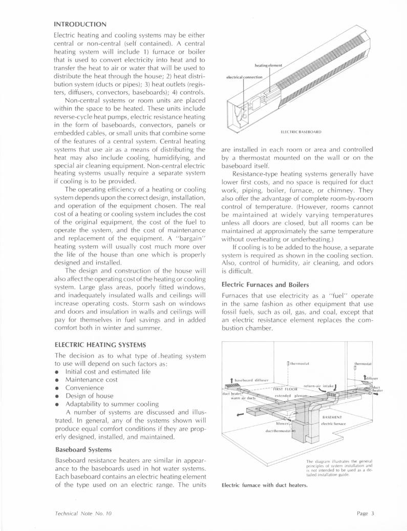
Baseboard Systems
Baseboard resistance heaters are similar in appearance to the baseboards used in hot water systems. Each baseboard contains an electric heating element of the type used on an electric range. The units
Technical Note No. 10
ELECTRIC BASEBOARD
are installed in each room or area and controlled by a thermostat mounted on the wall or on the baseboard itself.
Resistance-type heating systems generally have lower first costs, and no space is required for duct work, piping, boiler, furnace, or chimney. They also offer the advantage of complete room-by-room control of temperature. (However, rooms cannot be maintained at widely varying temperatures unless all doors are closed, but all rooms can be maintained at approximately the same temperature without overheating or underheating.)
If cooling is to be added to the house, a separate system is required as shown in the cooling section. Also, control of humidity, air cleaning, and odors is difficult.
Electric Furnaces and Boilers
Furnaces that use electricity as a "fuel" operate in the same fashion as other equipment that use fossi I fuels, such as oi I, gas, and coal, except that an electric resistance element replaces the combustion chamber.
~thermostat I I I
i
thermostat
~ I
The diagram illustrates the general principles of system installation and is not intended to be used as a de-tailed installation guide.
Electric furnace with duct heaters.
Page 3

It is also possible to use a boiler that is fitted with electric resistance heaters instead of a combustion chamber. The distribution systems are identical to those used for other hot water heating systems.
When an electric furnace is used as a central system, the thermostat is usually located in a central part of the house and the temperature in the house is controlled from one point. It is possible to achieve room-by-room control by modifying the system in the following manner: the central furnace is sized to maintain the circulated air at approximately 55°-65°. The thermostat which controls the central furnace is located in the duct system. A small duct heater is installed at the register in each room and it is controlled by a thermostat located within the room. A special control allows the duct heater to operate only when the blower is running.
Electric Ceiling Cable System
Electric cei I ing-cable systems can provide satisfactory heating. Electric resistance cables are attached to the ceiling lath and embedded in plaster, or the cables may be "sandwiched" between two layers of drywall. The panel attains a temperature of about 100° to 120°F. It is also possible to purchase a drywall material with the cables already embedded in the board.
Heating of the room takes place by the radiant effect of the warm panel and by convection of air moving over the panel and over the floor which is warmed by the radiant panel.
The cable lengths are made up of wire specifically designed for use in panel heating. Heating requirements are met by varying the length and spacing of the cable. The cable assemblies are equipped with non-heating leads, which permit connections to be made at the thermostat without having heated wires in the wall.
The diagram illustrates the general principles of system installation and is not intended to be used as a detailed installation guide.
Page 4
Ceiling cable system
When ceiling cable installations are used, the space above the panel should be insulated. This prevents excessive heating of the room above. Also, when this system is used in apartments, the use of insulation prevents the heating of upper apartments from the lower floors.
Lightweight, acoustic, or insulating plasters cannot be used over the cables, and caution must be used during construction to protect the cables from damage. Ceiling-cable systems:
• Are usually less expensive to install than other electric-resistance heating systems.
• Do not use any floor space. • Are used with thermostatic controls to give
room-by-room temperature control. • Do not interfere with furniture location. • Need supplementary heating equipment when
there are large glass areas in the room that can cause drafts across the floor.
• Limit possible modifications to ceiling and light fixture placement during remodeling.
• Very little if any maintenance needed. Thermostats should be inspected periodically for dirty, worn, or pitted contacts.
Heat Pumps
The operation of a heat pump is identical to the operation of compressor-cycle equipment. The only difference is that a valve system can be used to select which of two coils acts as the condenser and which the evaporator.
In the summer, the equipment operates identically to the compressor equipment described on page 6, with the condenser outside the house and the evaporator in contact with the air circulated within the house.
In the winter, the functions of the coi Is are reversed and the coil inside the house becomes the condenser and the coi I located outdoors the evaporator. Heat is extracted from the outdoor air, even when it is cold, and then transferred to the indoor air passing over the condenser. The heated air from the condenser is then distributed through the house. The system gets its name because it takes a quantity of heat from the outdoor air at low temperature, and, through a mechanical process, makes it possible to deliver the same quantity of heat, but at a much higher temperature, into the house. The work that is required to do this is represented by the power that is used by the compressor motor. The heat output of the system that is useful for heating indoor air may vary between 1 and 5 times the heat equivalent of the power required to run the compressor. The actual ratio depends on the temperature and humidity of the outdoor air and
University of Illinois SHC-BRC

HEAT PUMI'
of the indoor air. In the heating position, the coefficient of utilization, or effective efficiency, goes down as the outdoor air temperature gets colder, until it is no longer efficient to operate the equipment. At this point, supplemental resistance heaters are switched into the system.
For most heat pumps, air is used as the outdoor source for either extracting heat in the winter or rejecting heat in the summer. However, where water is available it can be used as a source, although the installation is more difficult. Heat pumps are avai I able in room-size or central-system size units.
condenser
Outside unit compressor and condenser.
Technical Note No. 10
Supplementary Heating
In every home there are areas where some additional heat is needed to supplement the central system. These areas are generally in bathrooms, infrequently used laundry rooms or workshops, and beneath sliding glass doors or large glass areas. Spot heating can be provided by the use of small fixtures that use infrared heating bulbs, or by small electric resistance units that use either a reflector or a fan to distribute the heat. To offset the drafts caused by convection from large glass areas, drop-in heaters are used that fit flush with the floor coverings.
ELECTRIC RESISTANCE UNIT
SUPPLEMENTARY HEATERS
COOLING SYSTEMS
When resistance type heating systems are used a separate cooling system is required for year-around comfort conditioning.
Separate, overhead duct systems are installed for central summer air conditioning. Supply outlets should be located in the ceiling or high on outside or inside walls. Air may be returned through a single central intake in a small, rectangular, one-story home, or by multiple intakes for larger structures. Return-air intakes are usually located in the ceiling of a hallway or high on an inside wall. Ducts located in unconditioned spaces (especially attics) must be well insulated to reduce heat gains and avoid moisture condensation. The advantages of a separate cooling system include: simpler duct system; no seasonal rebalancing; less possibility of drafts since the system is designed for cooling; and can be installed in homes with existing heating systems that are not readily adaptable to cooling. Disadvan-
Page 5

tages are: higher installation costs; uses more space; and if used, the servicing of attic or roof-mounted equipment may not be convenient.
Compressor-cycle Equipment
Most residential cooling equipment uses a "compressor-cycle" system. In compressor-cycle equipment, the refrigerant, usually Freon, is put under high pressure and high temperature as it passes through the compressor. In the condenser (an arrangement of finned tubes similar to the radiator in a car) heat is removed from the refrigerant by blowing outdoor air or pumping water over the fins, causing the refrigerant to condense into a liquid. At the expansion device, the pressure on the cooled liquid refrigerant is sharply reduced, and as it enters the evaporator, another radiator-! ike device, it evaporates into a gas. As it evaporates, heat is taken from the surrounding air or water that is passing over the evaporator.
As room air passing over the evaporator is cooled, moisture in the room air will condense on the fins or coils and be drained away. This dehumidifies the air, which is a major benefit of summer cooling in a humid climate. If insufficient room air is flowing through the evaporator (cooling coi I) the evaporator becomes very cold, and the coil temperature could fall below 32°F. If this happens, ice will form on the coil and block the passage of air. Cooling effectiveness is lost and continued operation could damage the equipment. Lack of air flow can be caused by a slipping or broken belt on the air blower or clogged air filters. Another frequent cause of icing of the evaporator is low refrigerant pressure, usually due to a leak causing a shortage of refrigerant.
Page 6
high-pressure gas
• liquid
D low-pressure gas expansion valve
-7 -7 -7 -7
1~==~~==~----~7 compressor
evaporator (cooling coil)
THERMOSTAT
CONTROLS
mercury switch
thermostat sensing element
adjustable heater
The heating and cooling systems described in this circular are operated by automatic controls. These devices include thermostats, hu midistats, safety controls, and switches to operate fans and pumps. They are designed to run the system automatically so that it functions only when heating or cooling is needed. This helps keep the house at an even temperature, which adds to the comfort of the occupants and reduces the cost of operating the system.
Thermostats
The heart of the control system is the thermostat, essentially a temperature-sensitive switch that turns the heating system (or cooling system) on and off. Some thermostats are designed so that various stages or parts of the heating system can be turned on or off so that the heat input is "modulated" to match the heat loss of the house. Many thermostats are equipped with small heating elements called anticipators. The anticipator raises the temperature within the thermostat case, giving it a false reading and causing it to turn the system off before the room reaches the desired temperature. The residual heat in the system will then bring the temperature up to the desired point. If there is not sufficient residual heat, the thermostat wi II sense the deficiency and turn the system on again. In this way the desired temperature is reached in small steps so that the house is not overheated, with a resultant waste of fuel and occupant discomfort.
In many instances, one thermostat is used to control the temperature in several rooms or the whole house. Actually, it can sense the temperature only in the room where it is located. For this reason it is important that the thermostat be located either
University of Illinois SHC-BRC

Thermostat should be located 2 to 4 feet from the floor.
where the temperature is representative of the whole house or where temperature control is most important. Locate the thermostat at a height of 2112 to 4 feet above the floor. Avoid locations on outside walls, near outside doors, or in bedrooms where windows may be left open. Likewise, do not place it near heat outlets, behind doors, on walls that receive heat from the sun or fireplace, or on walls that house heating pipes, ducts, or chimneys. Avoid locations that may interfere with furniture placement. Lamps, TV sets, or radios under a thermostat will give it false readings and result in poor control of the heating system.
In some cases, it may be desirable to divide the house into two or more zones for heating (or cool in g) control. With non-central systems (such as electric resistance baseboard or ceiling cable), zone control is relatively easy to achieve. With ducted or piped systems, the distribution I i nes must be specifically designed for this purpose. Zoning is used to help maintain the same temperature in various parts or levels of the house. Zoning should be considered for multi-level or large houses, or when there are unusual sun or wind exposures.
Zone control makes it possible to maintain an even temperature in rooms with varying sun and wind exposure.
Technical Note No. 10
A thermostat located in each zone controls a solenoid valve in the line serving that area in a hot water system or a motorized damper in the main duct going to the area in a warm air system.
The thermostat should be set at the point at which the occupants are most comfortable and left at that setting except for special circumstances. These special times occur at very cold outside temperatures, when heating is almost continuous. At that time, thermostats equipped with anticipators may have a tendency to "droop" and maintain a temperature a few degrees below the setting. In these cases, the thermostat setting wi II have to be adjusted. A setting above the desired temperature will not make the temperature rise any faster nor will a low setting cause the house to cool any faster. The speed with which the temperature in a house will respond to a change in the thermostat setting wi II depend on the type of heating system and the construction of the house.
The thermostat setting may be lowered 5 to 10 degrees during sleeping hours. Research indicates a savings of 5 to 10% in operating cost with night set-back.
Maintenance. A properly functioning thermostat will keep your home at comfortable temperatures. However, a number of things can affect its performance. The most common problem causing poor thermostat operation is dust covering the sensing element or contact points. A layer of dust will reduce the speed with which the thermostat feels a change in temperature, which allows the house to get too cold before the heating system
do not set thermostat at 90°
set it at temperature desired
A thermostat setting higher than 68° will not make the room temperature reach 68° any faster.
Page 7

comes on and lets it get too hot before it shuts the system off. To correct this problem, remove the cover from the thermostat and carefully vacuum the mechanism. If the material is caked on, a service call will be required.
Another occasional problem is that the thermostat loses its calibration. For example: the thermois set on 68° and the room temperature is more than 2° or 3° above or below this (72° or 64°). The easiest sol uti on is to set the thermostat at whatever position it takes to maintain the desired room temperature and mark this point. Some models have a calibration adjusting screw on the sensing coil mounting. Others require repositioning the thermostat on the wall so that it is level. To recalibrate a thermostat, use a good quality thermometer to measure the temperature near the thermostat. Then move the sensing element so that the contacts just open when the pointer is set at the room temperature. Some readjustment may be needed if an accuracy of 1 o or less is desired.
A third way that the thermostat can fai I is by a break in the anticipator. This may cause some overheating of the room before the furnace shuts off. If the variation between "on" and "off" is not too great, you can set the thermostat to a lower setting. Repair of the anticipator requires a good serviceman or replacement of the thermostat.
Older thermostats may have problems with corrosion of the contact points. They can be cleaned with a piece of bond paper or crocus cloth. (Be sure to shut off the power to the thermostat before you start to work.)
HUMIDISTATS
Humidistats are equipped with an element that senses a change in the moisture content of the air circulating around the instrument. An increase in the moisture content of the air wi II cause the sensing element to open the switch that controls the humidifying equipment, or the control can be wired so that an increase in the moisture content of the air closes the switch to operate exhaust fans or other dehumidifying equipment.
Maintenance. Maintenance and calibration of humidistats can sometimes be very difficult. Accumulations of dust or other foreign material on the sensing element (often a human hair or a special material which looks like packaging tape) can cause the controls to give wrong readings, or to stick.
It is nearly impossible to clean a humidistat without affecting its calibration. Cleaning can be done by washing the element in disti lied water,
Page 8
using a very soft bristle brush. Brush the water over the element until it appears clean. Then allow it to dry and check its accuracy. Some reliable means of measuring relative humidity is needed to reca~ibrate the humidistat. If a sling psychrometer is not available, you can measure the relative humidity to ±5% by wrapping a moist, thin cotton cloth around the bulb of a glass thermometer and blowing air across it with a small fan. Compare this temperature to the temperature of the air taken with the same thermometer without the moist cloth and locate the relative humidity on the chart below.
Adjust the contacts so they close when the pointer is set to the relative humidity shown on the chart.
Dry Thermometer Reading
60 65 70 75 80
0.0 40 5 .5 "'C 45 26 12 ~ QJ 50 48 33 19 11 5 ~ .. 55 73 52 36 QJ - 60 100 75 55 40 29 QJ E 65 77 58 44 0 E 70 * * 100 78 61 .. QJ 75 79 .:: 1- 80 * * * * 100 -QJ
% Relative Humidity ~
hygroscopic element (hairs or tape)
HUMIDISTAT
University of Illinois SHC-BRC

INSULATION
A satisfactory and efficient electric heating system depends upon the proper design and installation of the insulation. Effective insulation wi II save both on the initial cost of the heating equipment, because less heating capacity will be needed, and on the annual operating cost. A well-insulated house will also be cooler in summer, requiring less air conditioning capacity.
The effectiveness of insulation varies with thickness, type or kind, density, and method of installation. Different materials have different insulation values. A method of comparing the effectiveness of the insulation is to compare the resistance (R) values of the materials. Resistances are relative values, determined experimentally, and the higher the value the better the insulating effect.
The installed R-value for an insulation product will normally be marked on the bag or container that is used to ship the material. In addition, loosefill types of insulation will be packaged in bags marked with required installed densities, thicknesses, and area of coverage per bag required to meet a standard installed resistance. ·
Walls
For new homes, a good quality blanket or batttype insulation is recommended. Insulation should be the full thickness of the wall and fi II all cavities, voids, and partitions in outside walls, giving a total resistance value of R-11 to R-13. lnsu lation is installed after plumbing and wiring have been completed.
Ceilings
Loose-fill insulation or blown insulation should adequately cover all areas of the attic floor and should be installed as evenly as possible over the entire attic. The insulation should be protected from wind or ventilation dispersion. It should not be installed so that it blocks the required ventilation openings in the eaves or overhangs. Batt insulation does not blow away from ventilation openings. An R-value of 19 is recommended except when ceiling cable heating is used; then the R-value should be increased to 24.
Floors
Floors over unheated crawl spaces should be insulated to a value of R-13. Most of the time, however, the crawl space will have water pipes, drain pipes, and possibly duct work, and it should not be ventilated during the winter months. It is generally preferable to insulate the crawl space walls with one inch of polystyrene or polyurethane insulation attached to the walls. The space between
Technical Note No . 10
EAVE DETAILS
CRAWLSPACE
SLAB CONSTRUCTION
Page 9

the top of the foundation wall and the underside of the floor sheathing should also be filled with insulation to prevent heat loss at this point. In twostory houses the space between the first and second floors (band joist) along the outside walls should also be insulated.
If a concrete slab is used, a one-inch board of foamed polystyrene or polyurethane should be placed around the perimeter, extending two feet horizontally under the slab or two feet vertically down the inside of the foundation wall.
Basement Walls
In houses where the basement is to be heated for any length of time, some effort should be made to reduce the heat loss through the basement walls and windows.
All windows in the basement should be double glazed or fitted with storm panels. High quality windows should be used, not the normal "basement" sash.
Before insulating the basement walls, the homeowner should be assured that the walls are free of leaks or areas of dampness. If in doubt the walls should be treated with a waterproofing paint. If there are large leaks or cracks the wall. should be repaired before any insulation is applied.
Basement walls are normally insulated by applying insulation between furring strips fastened to the wall with cut nails, steel pins, adhesives, or a combination of both. On sound walls, a layer of 4-mil polyethylene behind the insulation and directly on the wall povides a means of controlling dampness. The furring strips are usually 1 x 2's or 2 x 2's depending on the thickness of the insulation. Generally one inch of polystyrene or urethane insulation board extending at least two feet below the outside ground level wi II be sufficient for most basements.
Windows and Doors
The space around windows and door frames should be filled with insulation before the inside finish is applied. Insulating glass or storm panels should be used throughout the house. Wooden windows have lower heat loss than metal windows. Metal window frames often have condensation problems unless there is a separate storm sash or a strip of insulating material between any metal exposed to the outdoors and metal exposed to indoor air. A window with insulating glass or a storm panel has 8 times the heat loss of a well-insulated wall. Minimizing the glass area and installing triple glazing (insulating glass pi us storm sash) wi II further decrease the heat loss of the house.
Page 10
WINDOW AND DOOR OPENINGS
Moisture Control
Houses designed to mm1m1ze energy use will be tightly built and have less outside air infiltrating into the house. This lack of air exchange can result in the excessive accumulation of moisture in the house, causing condensation problems within the structure.
A vapor barrier should be installed in the wall to prevent the accumulation of moisture in the insulation. The vapor barrier is installed on the warm side of the wall , i.e . facing the inside of the house, between the insulation and the inside finish material.
In new construction , the best vapor barrier is obtained by covering the inside of the insulated wa lis with a 2- or 4-mi I polyethylene sheet. The 4-mi I sheet is preferable since it is less I ikely to be torn during the construction process. When a vapor barrier is installed, the number of joints should be held to a minimum and care should be taken to prevent damage during or after installation. Joints in the barrier should be made over wall studs or joists and should be lapped at least two inches. Foil-backed drywall is the second choice for providing a vapor barrier. When insulation with an attached vapor barrier (foil or asphalt-laminated paper) is used, special care must be exercised during the installation of the material so that the vapor barrier is complete and unbroken and extends completely around all door and window openings.
The soil surface in a crawl space under the house should be covered with a vapor barrier of 4-mi I polyethylene sheets. Laps in the polyethylene sheeting should be at least 6 inches and the material should extend up the crawl-space walls to meet the crawl-space wall insulation.
In existing houses it is more difficult to achieve a good vapor barrier on the walls and ceilings. Two or three well-applied coats of gloss or semigloss alkyd paints will result in a fair to acceptable vapor barrier.
University of Illinois SHC-BRC

HUMIDIFIERS
In tightly built modern houses, too little humidity is seldom the problem. However, in large houses with few occupants or in houses where little cooking or clothes washing or drying is dome, there could be a problem of dry air in the winter. Moisture can be added mechanically by commercially available humidifiers. There are three general types available:
The pan type is the simplest but has limited capacity. The pan is inserted in the plenum of the furnace and wicking plates are used to draw water out of the pan where it is then evaporated into the air stream flowing over the plates.
The wetted-element type operates as air is forced through a wetted pad or filter. These units can be either portable or mounted on the furnace. Portable units are usually refilled manually and require more attention than the permanently installed humidifiers.
The atomizing type throws water in fine droplets from the surface of a rapidly revolving disk or a small nozzle. This type is available as a portable unit or installed in the duct or plenum of a central heating system. The minerals in hard water are left as the water evaporates, and a I ight coating of white dust can result over much of the furnishings in the house. In the two types previously listed, the minerals remain in the plates or pads and are discarded as the parts are replaced.
Humidifiers are controlled by humidistats and should be closely watched so that high humidity does not occur on extremely cold days when condensation is most likely to occur. Moisture accumulation on the inside surfaces of double glazed windows is the first indication of excessive humidity. If the outdoor temperature is 0° to 10°, the humidity should be no more than 20%; if 15-45°, 40%. The humidifier should be turned off during the summer since the humidity in the house can be expected to be 40-80%.
Continuous ridge and eave vents
Technical Note No. 70
VENTILATION
The ventilating fan is probably the best known method for odor removal. Such a fan can be used in the kitchen, bathroom, or utility room for moisture removal. Ductless kitchen hoods recirculate the air and may provide some degree of odor control but will not remove moisture from the kitchen. The outlets of the ventilating fans should be d ucted to the outside of the house and should not terminate in the attic. The dumping of moisture-laden air from the kitchen and bathroom into the attic can result in condensation on the attic sheathing and structure.
Areas above insulated ceilings should be vented to the outside to provide adequate air circulation above the insulation. One square foot of net ventilating area should be provided for every three hundred square feet of insulated ceiling area. If vents have louvers or a screen, compensation should be made for the loss of free ventilating area. The vents should be uniformly and equally spaced to provide good air circulation above the insulation. It is recommended that half the vents be installed in the eaves or the overhang of the house and the other half high in the attic space, either by the use of a continuous ridge vent or by individual vents located along the ridge beam.
In extreme cases, where natural ventilation is difficult to achieve because of the terrain or trees surrounding the house, it may be necessary to install an exhaust fan in the attic that is controlled by a humidistat. The humidistat operates the fan whenever the moisture in the attic becomes excessive. This same fan can be operated in the summer by a thermostat to reduce the cooling load on the house by exhausting hot air from the attic.
Sloped ceiling requires ventilation over insulation
Page 11

WHAT ABOUT THE OLD HOUSE?
Whether a house is old or new, the same principles apply for installing insulation and vapor barriers. A vapor barrier should be applied to the warm side (inside) of the house to prevent moisture within the house from entering the walls in the winter. Insulation is needed in the wall~ to reduce heat flow from the inside of the house to the outside.
In old houses, if the interior finish is cracked or in poor condition , it may be best to remove the finish (usually lath and plaster) and start over by placing insulation between the studs and joists. If new electrical wiring is to be installed, and an old house usually should be rewired, the wiring should be done after the finish is removed and before the insulation is installed. A vapor barrier equal to 4-m i I polyethylene should be installed over the insulated wall before applying the new interior finish.
If the interior finish is notto be removed, it is possible to blow the walls full of insulation through holes drilled near the top of the outside walls between the studs. A plumb bob should be dropped through each hole to be sure there is no obstruction in the stud space. If there is, another hole must be drilled below such obstructions as windows, fire stops,cross-bracing, etc. Existing wiring could also block the insulation from dropping to the bottom of the wall.
The application of a vapor barrier on the inside of a wall when the finish is not removed becomes a
Cold-side venting
Page 12
problem. Aluminum paint and certain oil-based paints help to retard vapor flow into the walls. In many cases, old homes may already have several coats of oil-based paint on the plaster, which gives a beginning of a reasonable vapor barrier. With no vapor barrier, paint peeling and staining of the siding can be problems.
Another method of reducing the possibility of condensation problems is to wedge-out or install small screened ventilators in the top and bottom course of siding. Because these ventilation methods allow the moist air within the stud spaces to escape, they are classified as cold-side venting.
Insulating the ceiling of an existing house is usually simple because the space above the ceiling finish is accessible through the attic. A 4-mil polyethylene vapor barrier can be installed over the ceiling and the space between the ceiling joists filled with either batt-type or loose-fill insulation.
The basement and/or crawl space wall should be insulated just as described for new construction. The earth surface in the crawl space should also be covered with a polyethylene sheet to prevent the moisture which evaporates from the surface from entering the house.
This procedure of applying insulation and a vapor barrier can bring an old house up to the heat-loss standards of a new house.
alternate: paper tube to soffit vent
Insulating existing attic
A complete list of publications of interest to the homeowner is available upon request from the Small Homes Council-Building Research Council , University of Illinois at Urbana-Champaign, One East Saint Mary's Road, Champaign , Illinois 61820.
University of Illinois SHC-BRC