homag double-sided automatic edgebanding machine, model ... · double-sided automatic edgebanding...
TRANSCRIPT

TECHNICAL SPECIFICATIONS PAGE 1 AUGUST 08, 2007
Homag Double-Sided Automatic Edgebanding Machine,
Model KAL 526/7/A12/25/S2
Double-sided machine for edgebanding and post-processing of various coiled edge
materials up to 3 mm (1/8”) thickness. Fixed side on left, movable side on right.
A linear guide way and rolling transports ride on hardened bases.
Continuous machine frame for flexible installation of processing units.
Precision panel conveyor device consisting of rolling conveyor chain, with ball
bearings at running and guiding surfaces, width of chain plates 70 mm (2-3/4").
Dogs manually adjustable for a maximum of four positions 0 mm to 25 mm (0" to 31/32"). Dog height adjustable via four-fold turret. Dog spacing 1000 mm
(39-3/8".) Dogs are selectable for operating with all dogs up, every second set of
dogs up or every third set of dogs up.
Max. panel width in front of dogs 1220 mm (48-1/16").
Motorized height adjustment of top pressure beam with driven V-belts.
Glue roller drive in case of feed stop.
Manual center support with roller guide.
Electronic width adjustment via rapid/slow gear drive with ballscrew spindles for precise positioning. Equipped with ball screw spindles and Cardan drive for
precise, repeatable positioning. Chip channel in machine frame.
Magnetic motor braking of conveyor chain.
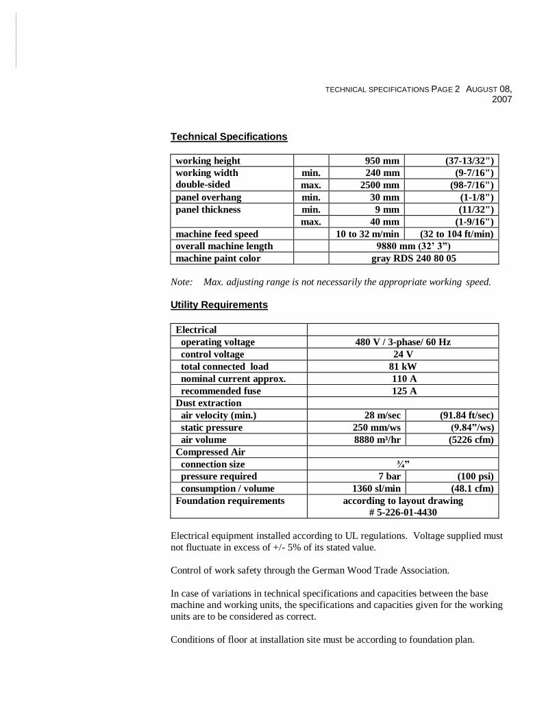
TECHNICAL SPECIFICATIONS PAGE 2 AUGUST 08, 2007
Technical Specifications
working height 950 mm (37-13/32")
working width
double-sided
min. 240 mm (9-7/16")
max. 2500 mm (98-7/16")
panel overhang min. 30 mm (1-1/8")
panel thickness min. 9 mm (11/32")
max. 40 mm (1-9/16")
machine feed speed 10 to 32 m/min (32 to 104 ft/min)
overall machine length 9880 mm (32’ 3”)
machine paint color gray RDS 240 80 05
Note: Max. adjusting range is not necessarily the appropriate working speed.
Utility Requirements
Electrical
operating voltage 480 V / 3-phase/ 60 Hz
control voltage 24 V
total connected load 81 kW
nominal current approx. 110 A
recommended fuse 125 A
Dust extraction
air velocity (min.) 28 m/sec (91.84 ft/sec)
static pressure 250 mm/ws (9.84”/ws)
air volume 8880 m³/hr (5226 cfm)
Compressed Air
connection size ¾”
pressure required 7 bar (100 psi)
consumption / volume 1360 sl/min (48.1 cfm)
Foundation requirements according to layout drawing
# 5-226-01-4430
Electrical equipment installed according to UL regulations. Voltage supplied must
not fluctuate in excess of +/- 5% of its stated value.
Control of work safety through the German Wood Trade Association.
In case of variations in technical specifications and capacities between the base machine and working units, the specifications and capacities given for the working
units are to be considered as correct.
Conditions of floor at installation site must be according to foundation plan.

TECHNICAL SPECIFICATIONS PAGE 3 AUGUST 08, 2007
Sub-Assembly Single Machine for Optimat KF/KL 26 Homag Unit #0006 infeed fence manually adjustable to different panel overhangs
includes four (4) inclined driven rollers
electro-pneumatically adjustable
dog counter pressure device with program control
min. panel length 250 mm (9-27/32") long using this device
Adjustable Dogs Homag Unit #0211
dog projection max. 25 mm (31/32")
Adjustable Infeed Fence Homag Unit #0005
with digital mechanical counter
Pre-Milling Unit Homag Unit #3481
with two (2) motors 4 kW, 150 cycle, 9000 rpm
for max. tool diameter of 125 mm (4-15/16")
equipped with trimming column two (2) horizontal and cross slides with spindle adjustment
electro-pneumatic horizontal jump movement of first motor
two (2) dust extraction hoods
air jet for panel cleaning
with two (2) DIA jointing heads 125 x 35 x 30 mm, DKN, Z = 2 x 3
max. workpiece thickness 30 mm (1-1/8")
includes electronic frequency inverter for control of motor speed and braking Noise Protection Stepped Homag Unit #0424
for pre-trimming unit
allows for inlay of long strips
centralized dust extraction port Execution II front loading area prepared for feeding of panels in front of chain dogs
Chain Track Extension
front loading area 1220 mm (48-1/16")

TECHNICAL SPECIFICATIONS PAGE 4 AUGUST 08, 2007
Panel Pre-Heater Homag Unit #2325
for heating of workpiece edge before glue application
max. 45 mm (1-25/32”) panel thickness
for improved edge quality and optimum bonding
QA 34 Quick Melt Gluing Unit Homag Unit #2123 specially designed by Homag - the original innovator of the quick melt system
lower reservoir unit is designed with only seven (7) wearing parts, which
allows for ease of adjustment and reduces maintenance costs ideally suited for quick heat-up time and color changes
one bolt secures lower unit to drive mechanism
special coupling eliminates alignment of universal drive joint digitally displayed thermostat for both upper and lower unit, along with
heated glue roller allow for excellent control of temperature for optimum
bonding results
heated glue roller individual adjustment for front and rear glue gates
upper reservoir for glue granules
glue roller diameter 34 mm (1-11/32") lower melting unit equipped with automatic control of glue level
Glue Roller Drive Homag Unit #2141
eliminates glue charring on the glue roller and lengthens the pot life of the glue
during idle running time of the machine
because it is thermostatically controlled, it activates to keep the glue roller drive continuing when lower unit has reached its melting temperature and
the feed track is stopped
Clamping Device for Glue Pot Homag Unit #2143
electro-pneumatic clamping of glue applicator at panel's trailing edge
Glue Container Back-Off Homag Unit #2145
in case feed track stops

TECHNICAL SPECIFICATIONS PAGE 5 AUGUST 08, 2007
Edge Feed Magazine HL Homag Unit #0000 with infeed angle of 13°
edge thickness 0.4 mm to 12 mm (.016" to 15/32")
edge width 12.7 mm to 65 mm (1/2" to 2-9/16")
max. cross section of edge 360 mm² (0.558 sq in) solid edge material feed
strip feed
Extension of Magazine A6/A12/A20 to six (6) Rolls Homag Unit #2458
instead of single roll
edge thickness 6 x 3 mm (1/8”)
roll diameter 6 x 830 mm (32-21/32”)
automatic or manual roll change
remnant edge length control at 2400 mm (94-15/32”)
Magazine Height Adjustment Homag Unit #2460
with threaded spindle adjustment
adjustable +5 mm to to5 mm (+13/64" to -13/64") Pressure Zone for Gluing Section Type C Homag Unit #2507 (P) one (1) driven pressure roller 200 mm (7-7/8") diameter
six (6) secondary pressure rollers 70 mm (2-3/4") diameter
with pneumatic pressure control for straight edges centralized manual adjustment with digital counter for edgeband thickness
Automatic Pressure Zone Adjustment Homag Unit #2596
for automatic positioning of pressure zone for varying edge thickness
Snipping Unit HL 81 .8kW Homag Unit #3049
for straight and chamfer snipping
with two (2) motors, 0.8 kW, 200 cycle, 1200 rpm
max. edge thickness for straight snipping 12 mm (1/2")
max. edge thickness for chamfer snipping 3 mm (1/8")
max. edge height 65 mm (2-9/16")
with two (2) carbide tipped saws 120 mm (4-23/32") diameter; t = 30

TECHNICAL SPECIFICATIONS PAGE 6 AUGUST 08, 2007
Adjustment Chamfer, Straight Homag Unit #3114
for automatic re-setting from straight snipping to chamfer snipping
manual motor adjustment required in case of modifications of edge thickness
Flush Trimming Unit 1.5 kW Homag Unit #3209
with two (2) motors, positioned one above the other, 1.5 kW, 200 cycle,
12,000 rpm
angle adjustment +/- 1°
with two (2) carbide tipped trimming cutters, 70 mm x 25 mm
(2-3/4” x 31-32”), HSK 25, z = 4
motors running against direction of feed
height adjustment with top pressure beam
2 TCT cutters 70 x 25 mm (2-3/4” x 31/32”), HSK 25, t = 4
includes electronic frequency inverter for control of motor speed and braking
Set of “I” System TCT Flush Trimming Cutters Homag Unit #3900
in place of standard tool
two (2) cutters 70 mm (2-3/4”) x 25 mm (31/32”), t=4, HSK 25 R
with integrated chip collecting system
up to 95 % of chips collected
high processing quality due to improved extraction
station dust extraction volume requirement reduced by as much as 50%
Profile Trimming Unit FF 12 Homag Unit #3503
For crosswise processing of postforming or softforming parts and for rounding
plastic edges at panel front and rear edge on top and bottom
prepared for mounting the processing motors
includes electronic frequency inverter for control of motor speed and braking
per tool type and edge thickness a separate changing device is required
max. edge thickness 6 mm (1/4")
max. panel thickness
o 40 mm (1-9/16") with processing
o 60 mm (2-3/8") without processing
min. panel length
o 120 mm (4-23/32") single-sided
o 80 mm (3-5/32") double-sided
max. feed speed 20 m/min (66 ft/min)
workpiece gap approx. 500 mm (19-11/16”)
without follow up control and without changing device and tools

TECHNICAL SPECIFICATIONS PAGE 7 AUGUST 08, 2007
Automatic Changing and Adjustment Device FF12 Homag Unit #3513
for radius and chamfer trimming with combination tool
four (4) motors, 0.4 kW each, 200 Hz, 12000 l/min
automatic adjusting device via axis on the unit beam for lateral positioning to
different edge thicknesses and for moving away out of the working area
chamfer and radius adjustment automatically adjustable
max. edge thickness for chamfer with radius cutter:
o in case of r = 1.5 0.6 mm
o in case of r = 2.0 0.8 mm o in case of r = 3.0 1.0 mm
chamfering angle approx. 15°
tool chuck HSK25
without tools
Radius Cutter Homag Unit #3562
set of four (4) insert cutters
with ten (10) reversible carbide inserts
70 mm (2-3/4”) x 16 mm (5/8”), HSK 25; t = 4
for r = 3 mm (1/8”)
Continuous Trimming Control Homag Unit #3533
allows profile end trimming station to be used for trimming top and
bottom radius detail as well as corner radii
includes dust extraction hood top and bottom
manual mechanical adjustment at unit required
Profile Scraping Unit Homag Unit #4510
tracing from top, bottom, and side
for chamfering or rounding off of pre-trimmed PVC edges
electro-pneumatic controlled air nozzles
max. edge thickness 5 mm (3/16")
max. lateral adjustment 50 mm (1-31/32")
height adjustment with top pressure
includes suction box for PVC chips
without tooling
Profile Knives for Scraping Unit Homag Unit #4535
for radius 3 mm (1/8”)

TECHNICAL SPECIFICATIONS PAGE 8 AUGUST 08, 2007
Pneumatic Adjustment Homag Unit #4522
for profile scraping unit
for electro-pneumatic lateral movement in and out of processing area
Edge Heating Device Optimat Homag Unit #2355
for removal of overstretch crazing when processing PVC edges top and
bottom
air heater with temperature adjustment
Edge Buffing Unit Homag Unit #4402
top and bottom with oscillation
two (2) motors, 0.25 kW, 60 cycles, 2850 rpm
incline and height adjustable with top pressure
oscillation device enables the utilization of complete disc width,
for top and bottom motor
equipped with two (2) cloth buffing wheels 150 mm x 50 mm x 25 mm
(5-29/32” x 1-31/32” x 31/32”)
Noise Reduction Enclosure Homag Unit #0415/0425
for edge trimming section
with centralized dust extraction ducts with viewing windows
illuminated for ease of operator inspection
Outfeed Transport Conveyor length approx. 400 mm (15-3/4")
Electronic Width Adjustment EB 02 Homag Unit #6263
with rapid and slow gear change-over
adjustment speed:
o rapid gear 3 m/min (9.8 ft/min)
o slow gear 25 mm/min (1 ft/min)

TECHNICAL SPECIFICATIONS PAGE 9 AUGUST 08, 2007
Electronic Control Homag Unit #6202 control with programmable memory (PLC)
indication of all inputs and outputs by means of luminous diodes
integrated line control for remote control of processing units
multi-tasking control of PLC for precise unit operation part number in machine at choice
compatible interface to all Homatic input systems
recommended environmental temperature min. +5° C (41° F), max. +35° C (95° F)
Monitor Input PC 22 Homag Unit #0000 user-friendly operator interface for control and administration of processing
programs of a machine
Hardware Power Control PC22 with PLC control (IEC61131)
modern control system on the basis of an industrial PC with 2 GHz and
512 MByte RAM
one (1) 1 hard disk fixed
one (1) hard disk for data securing
USB connection
TFT flat screen with PC – Keyboard and mouse
digital field bus system for infeed/outfeed and peripheral units
network connection Ethernet and network software
Software
Operating system Windows XP (US) embedded
virus protection 1:1 data securing (cloning) by means of a second hard drive
operation menu-guided with Windows standard
software kit WoodCommander with:
o easy, graphic supported creation and storage of machine programs o administration of tool data by tool macros
o operator guiding system (BDL) for display of necessary manual
adjustments at the machine in case of resets o error message in plain text
Schuler MDE Basic
integrated line control
remote diagnosis via modem

TECHNICAL SPECIFICATIONS PAGE 10 AUGUST 08, 2007
Increased Cooling Capacity for Optimat Homag Unit #6167 (1left; 1 right)
increase of cooling capacity for an environmental temperature of more
than 40 C (104F)
Diagnosis System WoodScout Homag Unit #6383 (1 left)
The WoodScout system systematically eliminates errors, leading to a considerable
decrease in down time. This software provides:
graphic-supported PLC diagnosis displayed in different levels
a data base system that allows the operator to enter the reason for the error as
well as the corrective measures. The next time an error occurs, the procedure to
correct it is displayed. The information is shared by all shifts and written by
customer for ease of understanding.
optimum support for the elimination of machine down-times
Documentation and Control Text: English Homag Unit # 8322
production instructions consisting of operator manual and maintenance
guidelines (hardcopy and CD ROM)
PC 22 on-screen control texts for machine operators
spare parts designations on CD ROM