hmr hmt hm2 - dettsonhmr hmt hm2 boilers with integrated by-pass a re designed for installation on...
TRANSCRIPT

OIL FIRED
HOT WATER BOILER
Printed in Canada
Printed on 100% recycled paper
Caution: Do not tamper with the unit or its controls. Call a qualified service technician.
Models :
HMR
HMT
HM2
2019-02-13 X40019 Rev. AE
Manufactured by:
DETTSON INDUSTRIES INC.3400 Industrial BoulevardSherbrooke, Quebec – Canada - J1L 1V8www.dettson.ca
INSTALLER / SERVICE TECHNICIAN:
USE THE INFORMATION IN THIS MANUAL FOR THE INSTALLATION AND
SERVICING OF THE FURNACE AND KEEP THE DOCUMENT NEAR THE
UNIT FOR FUTURE REFERENCE.
HOMEOWNER:
PLEASE KEEP THIS MANUAL NEAR THE FURNACE FOR FUTURE
REFERENCE.
HM2
HMT
HMR

2
PART 1 INSTALLATION
1.1) SAFETY LABELLING AND SIGNAL WORDS
DANGER, WARNING AND CAUTION The words DANGER, WARNING and CAUTION are used to identify the levels of seriousness of certain hazards. It is important that you understand their meaning. You will notice these words in the manual as follows:
DANGER
Immediate hazards which WILL result in death or serious bodily and/or material damage.
WARNING
Hazards or unsafe practices which CAN result in death or serious bodily and/or material damage.
CAUTION Hazards or unsafe practices which CAN result in minor bodily and/or material damage.
It is important that you have a qualified technician install your boiler.
WARNING
• This boiler is designed to provide you with comfort, savings and reliability for many years to come. However, its performance depends on the appliance being installed, brought on-line, and maintained in accordance with the instructions provided in this manual.
• If the heat exchanger is subject to corrosion caused by the constant presence of air or oxygen in the water due to frequent water changes, an improperly designed distribution system or the use of plastic piping without oxygen barrier, the warranty will not be applicable.
• This boiler is equipped with a burner designed to burn only No. 2 fuel oil (furnace oil). Never attempt to burn used motor oil or any oil containing gasoline.
• Make sure that the boiler and system are filled with water and that all air has been bled before attempting to start the burner.
• Never operate the burner above the maximum temperature indicated on the boiler nameplate.
• Never attempt to start the burner when the combustion chamber contains excess oil, is overheated, or when a strong smell of oil permeates the appliance.
• Close oil valves if the boiler will not be in use for an extended period of time.
• Never store garbage or combustibles near the boiler.
• Never burn garbage or paper in your boiler.
• DO NOT TAMPER WITH THE UNIT OR ITS CONTROLS.
1.2) UNIT IDENTIFICATION It is very important that you consult Figures 1 to 3 to identify the characteristics of each of the models offered in the “HMR - HMT – HM2” series. Figure 1: “HMR” boilers without sanitary hot water coil and
with a 13 cm (5") flue-pipe. The models are identified as HMR-080, HMR-092, HMR-103 and are available with either Beckett or Riello burners.
Figure 2: “HMT” boilers with or without sanitary hot water coil and with a 15 cm (6") flue-pipe. The models are identified as HMT12, HMT14, HMT16 and HMT18 and are available with either Beckett or Riello burners. These boilers are also approved with sealed combustion systems model VTK.

3
Figure 3: “HM2” boilers with or without sanitary hot water coil and with a 20 cm (8") flue-pipe. The models are identified as HM-185, HM-212, HM-240, HM-266 and HM-293. Available with the Beckett and Riello burners.
Each of these boilers has its own characteristics: location of return and supply pipes, sanitary hot water coil, relief valve and thermo manometer, diameter of the flue-pipe, etc.
1.3) DELIVERY Carefully check your boiler upon delivery for any evidence of damage that may have occurred during shipping and handling. Any claims for damages or lost parts must be made with the Transport Company.
1.4) INSTALLATION Your unit must be installed according to regulations as set out by competent authorities. Refer to the CSA B139 Installation Code.
1.4.1) Positioning The boiler must be installed in a clean and dry area, as closely as possible to a chimney. The boiler is NOT approved for installation on a combustible floor. See sketch below for an example of a non combustible floor construction.
The unit must be installed in a location where the ambient temperature is over 15°C (60°F).
1.4.2) Clearances The following minimum clearances from combustible surfaces must be observed:
Top: 22.86 cm (9")
Flue-pipe: 22.86 cm (9")
One side: 7.62 cm (3")
Other side: 0.60 m (24")
Front (from the cabinet) 0.60 m (24")
Rear: 7.62 cm (3")
1.5) WIRING The boiler must be connected to a 15 amp / 120 Vac protected circuit. The installer must wire the boiler according to the appropriate electrical diagram. Refer to typical wiring diagrams, Figures 5.1 to 5.5. All wiring must be in accordance with the “Canadian Electrical Code” CSA C22.1/ Part I.
CAUTION Always select the wiring diagram based on the distribution system (piping) and whether or not the boiler has a sanitary hot water coil. “HMR – HMT – HM2” boilers with integrated by-pass are designed for installation on any type of distribution (piping) system that is equipped with a circulating pump such as finned tube baseboard and cast iron radiators as shown in Figure 4. The integrated by-pass permits a stabilisation of the temperature rise between the supply and return pipes to approximately Δ11oC (Δ20oF), whatever the return temperature. In addition, the integrated by-pass prevents condensation in the boiler when using the circulator contact available on the boiler aquastat. This way, thermal shocks in the pipes are eliminated, off-cycling of the circulator is reduced and water temperature throughout the system is better controlled. If more than 1 circulator is used, we recommend the use of an RC-02 circulator control.
1.6) OIL SUPPLY The installation of the oil tank and lines must be in accordance with local codes and regulations. The burner can be hooked up to a one pipe system if the oil level in the tank is always above the burner. On an outside, above ground fuel tank hook-up, a one pipe system with a nominal dimension of 1.3 cm (½") diameter is ideal. Be sure to install the oil filter and at least 3 m (10') of piping inside the building, to allow the fuel oil to warm up in very cold weather, before reaching the burner. The oil pump configuration is for a 1 pipe system. Insert the by-pass plug for a 2 pipe system (refer to the manufacturer’s Instruction Manual). The installation must include an oil filter and a shutoff valve. Ensure that the piping has no leaks and that there are no obstructions. Do not use couplings or compression fittings on oil lines. On a two pipe system, use the same diameter pipe for both the suction and the return lines and set them at the same depth in the oil tank. Additional information can be found in the burner installation manual provided with your boiler. Check the entire oil distribution system for leaks at the beginning of each heating season.
TABLE 1 Chimney draft
Model Chimney size
Connecting pipe Recommended draft Minimum Maximum
HMR 12.70 cm (5") 15.24 cm (6") 12.70 cm (5") 8.71Pa (0.035")
HMT 12.70 cm (5") 15.24 cm (6") 15.24 cm (6") 8.71Pa (0.035")
HM2 17.78 cm (7") 20.32 cm (8") 20.32 cm (8") 12.44Pa (0.050")

4
1.7) CHIMNEY
1.7.1) Chimney draft
The chimney draft must be strong enough to ensure the safe and reliable operation of your unit.
1.7.2) Installation
The connecting flue pipe diameter must never exceed that of the chimney and its horizontal runs should have a minimum upward slope toward the chimney of 2 cm per 1 m (1/4" per foot) of run. The use of a damper in the connecting flue pipe is strictly prohibited. The use of a draft control is compulsory. Its omission constitutes sufficient grounds for voiding the warranty on the unit.
NOTICE It is possible that an efficient hot water boiler will cause the formation of condensation on the three outer sides of an outside chimney. Should this happen, a chimney liner or an “SMH” side wall venting system should be installed.
1.7.3) Side wall venting
“HMR-HMT-HM2” hot water boilers are approved for installation with the SMH side wall venting system. HMT hot water boiler is also approved for installation with the VTK sealed combustion system. If such a system is used, please refer to the installation manual supplied with the venting system.
1.8) BLOCKED VENT SHUT-OFF (BVSO)
For chimney venting
WARNING
IT IS IMPERATIVE THAT THIS DEVICE BE INSTALLED BY A
QUALIFIED SERVICE TECHNICIAN.
This device is designed to detect the insufficient evacuation of combustion gases in the event of a vent blockage. In such a case the thermal switch will shut down the oil burner. The device will then need to be restarted MANUALLY.
Refer to the wiring diagrams and the detailed instructions supplied with the BVSO for the installation and wiring procedures. The length of wires supplied with the unit is such that the safety device must be installed between the flue outlet of the appliance and the draft regulator, as indicated in the instructions.
It is further imperative that the BVSO be maintained annually. For more details refer to the instructions supplied with the device itself, as well as Section 3 of this Manual.
1.9) BURNER INFORMATION
The burner is shipped in a box, separate from the boiler and must be installed as follows:
1. Check that the model number on the burner carton matches the one on the boiler nameplate;
2. Remove the burner from its box;
3. Check the electrode settings;
4. Install the burner on the boiler, using the nuts which are already on the studs. Be sure to install the fireproof gasket supplied with the burner. Also, ensure that the end of the blast tube is flush with the inside surface of the combustion chamber when installing a Riello burner with an adjustable flange;
5. Connect the oil pipe(s) to the burner pump;
6. Wire the electrical connections in accordance with the appropriate diagram (see Section 1.5.)
1.10) COMBUSTION AIR SUPPLY
In order to function reliably, every oil heating system requires an adequate supply of combustion air. If the boiler must be installed in a confined area, 2 permanent openings must be provided. Both openings must be sized at 240 cm2/l (1 ft2) per U.S. gallon of oil burned per hour. One opening must be located near the ceiling, the other near the floor.
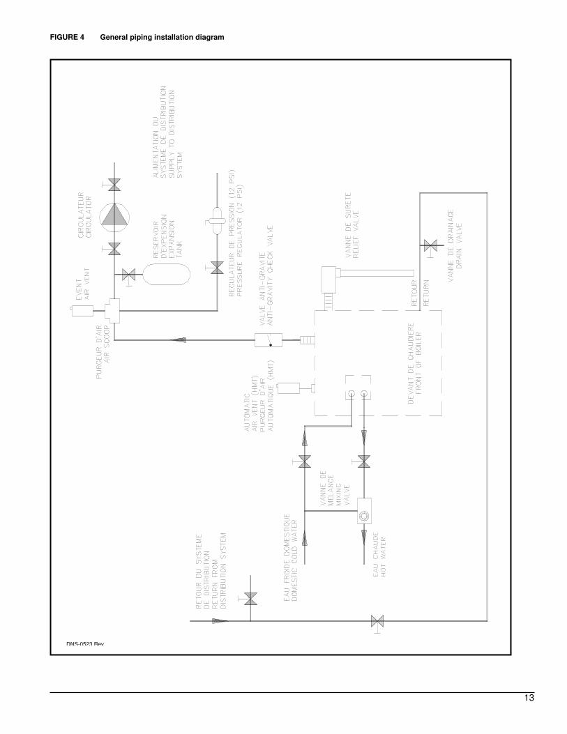
1.11) PIPING
The satisfactory operation of your boiler depends greatly on the installation of your plumbing. Refer to Figure 4.
In any event, the installation must include:
1. A pressure reducing valve, set at 83 kPa (12 psi), installed on the boiler cold water supply;
2. An expansion tank pressurized to 83 kPa (12 psi), installed on the piping;
3. An automatic air vent, to eliminate trapped air in the boiler;
4. A correctly sized water circulator, installed on the heating loop;
5. Stop valves and threaded unions, installed on the return and supply pipes of the boiler.
Always use quality pipe sealant on all threaded connections and ensure that these connections are well tightened. Avoid flushing the system when the boiler is a replacement for an existing one, to limit oxygen from getting into the system.
1.12) BVSO PERFORMANCE TEST The purpose of the following test is to check that the electrical outlet on the furnace, designated to the BVSO, is functional.
1. Start up the burner; 2. Remove the three-pole plug from the BVSO outlet on the
furnace; 3. The burner must shut-off immediately.
If the test is not in line with the above, call a QUALIFIED SERVICE TECHNICIAN.
CAUTION
NEVER use the “interrupted ignition” function if a Honeywell R7184 series combustion relay is installed on the burner.
CAUTION
A positive pressure venting system (Sealed Combustion System or Direct Vent) MUST NOT use the BVSO. Follow the instructions supplied with the venting system.
CAUTION
To avoid water damage and/or scalding due to relief valve operation, a discharge line must be connected to the valve outlet and run to a drainage area. The discharge line shall be installed in such a way that it will allow for the complete drainage of the valve and discharge line.

5
1.13) SANITARY HOT WATER HEATING COIL Before attempting to install a coil, always check the water quality to avoid premature scaling, which quickly renders your installation inefficient. Consult a specialist and have a water treatment system installed, if necessary. Locate the water inlet with the marking “IN”. We strongly recommend the use of a thermostatic mixing valve to achieve safe and optimal operation from the installation.
1.14) THERMOSTAT The thermostat must be mounted on an inside wall, approximately 1.5 m (5') above the floor. The location should be such that the thermostat is not subjected to air currants and/or exposed to direct sunlight.
1.15) DRAFT REGULATOR For chimney venting, a barometric draft regulator must be installed on the connecting pipe between the chimney and the boiler. It must be located in an easily serviceable location. Please refer to the installation instructions supplied with it.
PART 2 OPERATION
We recommend that a qualified service technician start-up and service your boiler. Ensure that the boiler and the system are always full of water and that all air has been bled before starting the burner.
2.1) FUEL Use only No. 2 fuel oil. Never attempt to use a heavier fuel oil, gasoline, motor oil or any other sort of fuel with your boiler.
2.2) START UP 1. Make sure that the tank contains fuel oil and that the fuel and
water valves are open;
2. The main power switch must be “OFF”;
3. Set the Limit Control to the desired temperature, for example 82o C (180o F);
4. Install a 0 - 1400 kPa (200 psi) pressure gage on the oil pump. The use of a suction gage may also be appropriate at the oil pump inlet, if suction of over 20.7 kPa (3 psi) may be encountered;
5. Pre-adjust the burner according to the specifications of Tables 2, 3 or 4. These specifications should only be used as a reference for initial start-up. Refer to the manual provided with the burner for further information on adjustments;
6. Turn the main switch “ON” and start the burner by setting the thermostat to its maximum;
7. Air can be bled from oil lines through the bleed port on the oil pump. If there is no ignition and the burner combustion relay goes into safety mode, see Section 2.3 below;
8. Adjust the oil pressure to the specified value in Tables 2, 3 or 4;
9. Adjust the chimney draft as specified in Table 1. Take this reading midway between the draft regulator and the outlet of the boiler;
10. Adjust the burner air band(s) for a smoke scale reading of 0 on the Bacharach scale;
11. Analyse the combustion gases with an appropriate instrument and set the burner accordingly.
Note: If a burner cabinet is used, ensure that all tests are done with this cabinet in place. Do not forget to tighten the adjustment screws once the burner is adjusted, before putting the burner cabinet back permanently.
12. Check the correct operation of the temperature controls and the
burner combustion relay;
13. Adjust the limits and the thermostat to the desired set points. Be sure to avoid operating settings which will result in the boiler water temperature going below 60°C (140°F).
2.3) RESTARTING AFTER IGNITION FAILURE 1. Check the oil level in the fuel tank;
2. Make sure the fuel supply valve is open;
3. Make sure the oil filter is not clogged;
4. Check the electrical circuit (fuse or breaker);
5. Check the burner electrode settings. Refer to the burner instruction manual;
6. Check if the thermostat is calling for heat;
7. Check for air in the oil pump suction line. If after following these steps and pressing the red Burner Reset Button, the burner still does not fire, call a qualified service technician. Never attempt to re-start the burner if excess fuel oil or fumes have accumulated in the combustion chamber.
2.4) SUMMER SEASON Make sure the fuel oil valve is closed when the boiler is not in use for a long period of time.
2.5) START-UP AT THE BEGINNING OF THE HEATING SEASON
1. Clean the chimney, the connecting flue pipes and the boiler.
Follow the steps in Section 3.6);
2. Replace the oil filter;
3. Have the burner electrodes cleaned along with the burner retention head and change the nozzle;
4. Check the operation of the high temperature Limit Control;
5. Check the operation of the circulating pump.

6
PART 3 MAINTENANCE
3.1) MAINTENANCE The area around the boiler must be kept free of combustibles, excessive dust and humidity, and highly flammable products at all times. Fresh air openings to the boiler and the boiler room must be kept clear. Repair any water and oil leaks without delay.
3.2) NOZZLE A dirty or clogged nozzle can prevent ignition or cause odours. If this is the case, it must be replaced.
3.3) FUEL TANK Regularly check the level in the fuel tank. Should the tank run dry, the fuel lines will have to be bled before restarting the burner.
3.4) OIL FILTER Replace the oil filter at the beginning of each heating season.
3.5) BURNER AND CIRCULATING PUMP MOTORS
Motors should be lubricated at least once a year (except permanently lubricated motors), with 2 to 3 drops of SAE 20 detergent-free oil.
3.6) CLEANING THE BOILER 1. Turn the main power switch “OFF” before cleaning;
2. Remove and clean the connecting flue pipe, sweep and check the chimney;
CAUTION The boiler being equipped with a sound trap, make sure not to damage the acoustical material when cleaning the boiler. The use of a flexible cleaning brush is strongly recommended.
3. Remove the smoke box and the fire tube baffles and clean the fire tubes, with the help of a 5 cm (2") diameter steel brush.
4. Remove the burner and clean the combustion chamber. Take care to not damage the ceramic bottom insulation;
5. Examine the cleaned surfaces for corrosion and correct the cause, as needed;
6. Re-install all components in their original positions and re-adjust the unit.
3.7) BLOCKED VENT SHUT-OFF (BVSO) CLEANING
For continued safe operation, the Blocked Vent Shut-Off System (BVSO) is required to be inspected and maintained annually by a qualified service technician.
1. Disconnect power to the appliance.
2. Remove the two screws holding on the BVSO assembly cover.
3. Remove the cover.
4. Remove the two screws holding the control box to the heat transfer tube assembly. Sliding the control box in the appropriate direction will unlock it from the heat transfer tube assembly;
5. Carefully remove any build-up from the thermal switch surface;
CAUTION Do not dent or scratch the surface of the thermal switch. If the thermal switch is damaged, replace-ment is required. 6. Clear and remove any build-up or obstruction inside the heat
transfer tube.
7. Re-mount, lock and fasten the control box with the 2 screws removed in step 4;
8. Re-attach the assembly cover with the screws removed in step 2.
9. Re-establish power to the appliance.
3.8) BOILER PURGE It is recommended to purge the boiler for about 1 minute at least once a year, to evacuate sludge and sediment that has accumulated at the bottom of the boiler. Proceed as follows:
1. Let the boiler cool down;
2. Hook-up a garden hose to the drain valve have a bucket ready;
3. Open the valve and drain the water into the bucket until it comes out clean.
3.9) SPARE PARTS It is always recommended to replace a defective part with a genuine part, available from your supplier.
3.10) TROUBLESHOOTING
Note: It is normal to have to wait several hours after a cold start, before the house is well heated, because of the thermal inertia of the building.

7
PART 4 INFORMATION
Model:
Serial number:
Installation date of the boiler:
Service telephone # - Day:
Night :
Dealer name and address :
START-UP TEST RESULTS
Nozzle:
Pressure :
lb/in2
Burner adjustments :
Primary air
Fine air
Draw Assembly
CO2 :
% Smoke scale :
(Bacharach)
Gross flue temperature:
°F
Ambient temperature:
°F
Chimney draft:
" W.C.
Overfire draft :
" W.C.
Test performed by :

8
TABLE 2 Technical specifications HMR
Beckett Burner AFG-F HMR-80-B HMR-92-B HMR-103-B HMR-121-B
Capacity (BTU/h) 79000 90000 101000 116000
Input (USGPH) 0.65 0.75 0.85 1.00
Retention head F0 F3 F3 F3
LFRB* Yes Yes Yes No
Nozzle (Delavan) 0.65-80W 0.75-80W 0.85-80W 1.00-80A
Pressure (PSI) 100 100 100 100
Insertion tube (in.) 2 7/8 2 7/8 2 7/8 2 7/8
Adjustment main air band 0 0 0 1
Adjustment air shutter 8 9 9 9
AFUE % 84 83,5 80,9 80,6
Riello burner 40-F3 HMR-80-R HMR-92-R HMR-103-R N/A
Capacity (BTU/h) 79000 91000 100000 -
Input (USGPH) 0.65 0.75 0.85 -
Nozzle (Delavan) 0.60-80A 0.65-70B 0.75-70B -
Pressure (PSI) 120 135 130 -
Insertion tube (in.) 3 9/16 3 9/16 3 9/16 -
Adjtusment air shutter 3.8 4.1 6.1 -
Adjustment turbulator 0 0 0 -
AFUE % 84,9 84,4 81,8 -
* LFRB = Low Firing Rate Baff le (refer to the burner manual)

9
TABLE 3 Technical specifications HMT * LFRB = Low Firing Rate Baffle (refer to the burner manual)
Beckett Burner AFG-F
(With chimney) HMT-12-B HMT-14-B HMT-16-B HMT-18-B
Capacity (BTU/h) 118000 141000 158000 175000
Input (USGPH) 1.00 1.20 1.35 1.50
Retention head F6 F6 F6 F6
LFRB* No No No No
Nozzle (Delavan) 1.00-70A 1.20-70A 1.35-70A 1.50-70A
Pressure (PSI) 100 100 100 100
Insertion tube (in.) 2 7/8 2 7/8 2 7/8 2 7/8
Adjustment main air band 0 1 1 2
Adjustment air shutter 7 5 6 5
AFUE % 82,1 82,4 81,6 80,9
Riello Burner 40-F5
(With chimney) HMT-12-R HMT-14-R HMT-16-R HMT-18-R
Capacity (BTU/h) 120000 142000 159000 175000
Input (USGPH) 1.00 1.20 1.35 1.50
Nozzle (Delavan) 0.85-70B 1.00-70B 1.10-70B 1.25-70B
Pressure (PSI) 140 145 150 145
Insertion tube (in.) 3 9/16 3 9/16 3 9/16 3 9/16
Adjustment air shutter 2,5 2,75 3,5 4,5
Adjustment turbulator 0 1 2 3
AFUE % 85.7‡ 84,6 83,4 82,4
Riello Burner 40-BF5
(Sealed combustion) HMT-12-R HMT-14-R HMT-16-R N/A
Capacity (BTU/h) 120000 142000 159000 -
Input (USGPH) 1.00 1.20 1.35 -
Nozzle (Delavan) 0.85-80B 1.00-80B 1.10-80B -
Pressure (PSI) 140 145 150 -
Insertion tube (in.) 3 9/16 3 9/16 3 9/16 -
Adjustment air shutter 2 2 3 -
Adjustment turbulator 3 5 5 -
AFUE % 85.7‡ 84,6 83,4 -
‡ =

10
TABLE 4 Technical specifications HM2
Beckett Burner AFG-V1 HM-185-B HM-212-B HM-240-B HM-266-B HM-293-B
Capacity (BTU/h) 185000 215000 243000 270000 296000
Input (USGPH) 1.50 1.75 2.00 2.25 2.50
Retention head MD-V1 MD-V1 MD-V1 MD-V1 MD-V1
LFRB* No No No No No
Nozzle (Delavan) 1.50-70B 1.75-70B 2.00-70B 2.25-70B 2.50-70B
Pressure (PSI) 100 100 100 100 100
Insertion tube (in.) 2 7/8 2 7/8 2 7/8 2 7/8 2 7/8
Adjustment main air band 6 7 4 6 5
Adjustment air shutter 4 4 3 4 4
Head adjustment V1 1 2 3 5 6
Riello Burner 40-F10 HM-185-R HM-212-R HM-240-R HM-266-R HM-293-R
Capacity (BTU/h) 185000 215000 243000 270000 296000
Input (USGPH) 1,50 1,75 2,00 2,25 2,50
Nozzle (Delavan) 1.25-60B 1.50-45B 1.65-45B 1.75-45B 2.25-60B
Pressure (PSI) 145 135 145 165 125
Insertion tube (in.) 3 1/8 3 1/8 3 1/8 3 1/8 3 1/8
Adjustment air shutter 3,4 4,5 3,4 5,5 4,5
Adjustment turbulator 0,0 1,0 2,0 3,0 4,0

11
FIGURE 1 HMR Boiler
FIGURE 2 HMT boiler with or without coil

12
FIGURE 3 HM2 boiler with or without coil
13
FIGURE 4 General piping installation diagram
DNS-0523 Rev.

14
FIGURE 5.1 Typical connection without sanitary water coil Control used: “Triple action” temperature control - Honeywell # L6081A or White Rodgers # 11C61 (Aquastat Triple, Hi-Lo/Circ)
Operation and typical settings
Burner Stop Thermostat open
Start Thermostat close
Circulator Stop “Circ” contact opened
Start “Circ” contact closed Maximum High-Limit setting = 210°F
DNS-0144 Rev. H

15
FIGURE 5.2 Typical connection for system with finned tube radiators and without sanitary water coil Control used: - “Triple action” temperature control Honeywell # L6081A or White Rodgers # 11C61 (Aquastat Triple, Hi-Lo/Circ) - Pump relay Honeywell # RA89A or White Rodgers # 809A
Operation and typical settings Maximum High-Limit setting = 210°F
DNS-0145 Rév. G
Burner Stop "Lo" contact opened
Start "Lo" contact close
Circulator Stop Thermostat opened -or- All zone valves closed
Start Thermostat closed -or- One zone valves opened
°F °C °F °C °F °C °F °C
200 93 10 5.6 180 82 10 5.6
Set Diff. Set Diff.
"Hi" "Lo / Circ"
Settings:
Operation: (the boiler is maintained warm)
16
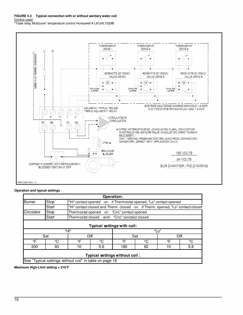
FIGURE 5.3 Typical connection with or without sanitary water coil Control used: “Triple relay Multizone” temperature control Honeywell # L8124L1029B
Operation and typical settings Maximum High-Limit setting = 210°F
DNS-0943 Rev. C
Burner Stop "Hi" contact opened -or- if Thermostat opened, "Lo" contact opened
Start "Hi" contact closed and Therm. closed -or- if Therm. opened, "Lo" contact closed
Circulator Stop Thermostat opened -or- “Circ” contact opened
Start Thermostat closed -and- “Circ” conctact closed
°F °C °F °C °F °C °F °C
200 93 10 5.6 180 82 10 5.6
Typical settings without coil :
"Hi" "Lo"
See "Typical settings without coil" in table on page 18
Typical settings with coil:
Operation:
Set Diff. Set Diff.

17
FIGURE 5.4 Typical connection with or without sanitary water coil Control used: Triple relay temperature control Honeywell # L8124L1102B
Operation and typical settings Maximum High-Limit setting = 210°F
DNS-0146 Rev. C
Burner Stop "Hi" contact opened -or- if Thermostat opened, "Lo" contact opened
Start "Hi" contact closed and Therm. closed -or- if Therm. opened, "Lo" contact closed
Circulator Stop Thermostat opened -or- “Circ” contact opened
Start Thermostat closed -and- “Circ” conctact closed
°F °C °F °C °F °C °F °C
200 93 10 5.6 180 82 10 5.6
Typical settings without coil :
"Hi" "Lo"
See "Typical settings without coil" in table on page 18
Typical settings with coil:
Operation:
Set Diff. Set Diff.

18
FIGURE 5.5 Typical connection with or without sanitary water coil Control used: - “Triple action” temperature control Honeywell # L6081A or White Rodgers # 11C61 (Aquastat Triple, Hi-Lo/Circ) - Pump relay Honeywell # RA89A or White Rodgers # 809A
Operation and typical settings
Burner Stop Hi" contact opened -ou- if Thermostat opened, "Lo" contact opened
Start "Hi" contact closed and Therm. closed -or- if Therm. opened, "Lo" contact closed
Circulator Stop Thermostat opened -or- “Circ” contact opened
Start Thermostat closed -and- “Circ” contact closed
°F °C °F °C °F °C °F °C
180 82 10 5.6 140 60 10 5.6
Typical settings with coil :
"Hi" "Lo / Circ"
See "Typical settings with coil" in table on page 16
Typical settings without coil:
Operation:
Set Diff. Set Diff.

19
PARTS LIST Model : HMR (HM-080 @ HM-103)
B50019B

20
PARTS LIST Model : HMR (HM-080 @ HM-121) L50019B
ITEM PART # DESCRIPTION
1 B00472-01 FLOOR
2 B00619-01 FLOOR INSULATION
3 B00618-01 COM BUSTION CHAM BER BOTTOM INSULATION
4 F03F004 FLOOR SCREW (Quantity: 4)
5 B00909 HEAT EXCHANGER
6 G08F004 REDUCER BUSHING 1" NPT x 1/2" NPT
7 G11Z001 DRAIN FAUCET 1/2"NPT
8 B00864-02 FLUE BAFFLE (Quantity: 11)
9 G04F002 OUTLET PIPE FITTING
10 G11F012 RELIEF VALVE 30 PSI 3/4" x 3/4"
11 B01651 HEAT EXCHANGER OUTSIDE INSULATION
12 B02904 "U" SHAPED CASING
13 G14G001 FLANGE 2-7/8" OD 1" ID LDPE WHITE
14 B00929 TOP PANEL (Without well)
15 B00701-01 TOP INSULATION
16 F07F011 HEX NUT 3/8"-16NC ZINC (Quantity: 7)
17 B00946 SOUND TRAP ASSEM BLY (with shield & insulation)
18 B00419 GASKET, BURNER
19 R02J003 WELL 3/4" NPT
20 B00927 FRONT PANEL
21 R02L001 TRIDICATOR 0-75 PSI 1/4" NPT
22A R02H005 TRIPLE ACTION AQUASTAT L6081A
22B R02H006 TRIPLE ACTION AQUASTAT M ULTIZONE L8124L
23 B00964 ELECTRICAL KIT
24A K02014 OBSERVATION DOOR KIT (before 99/09)
24B B01842 OBSERVATION DOOR ASSEM BLY (after 99/09)
25 K08006 SOUND TRAP INSULATION KIT
26 B00834-09 SOUND TRAP INSULATION SHIELD
27 B00834-10 SOUND TRAP BAFFLE INSULATION SHIELD
28 B00621-24 SOUND TRAP BAFFLE INSULATION
29 B00892 SOUND TRAP BAFFLE
30 B00702-12 GASKET, SOUND TRAP (25 foot ro ll)
31 B03029 ELECTRICAL KIT, BVSO
32 Z06G001 BLOCKED VENT SHUT-OFF BVSO-225

21
PARTS LIST Model : HMT (HMT-12 @ HMT-18) S/N greater than D010408972
B50020B

22
PARTS LIST Model : HMT (HMT-12 @ HMT-18) S/N greater than D010408972 L50020B
ITEM PART # DESCRIPTION
1 B02349-01 HEAT EXCHANGER (Without co il)
2 B01910 HEAT EXCHANGER OUTER INSULATION
3 G08F004 REDUCER BUSHING 1" x 1/2" BLACK
4 G11Z001 DRAIN FAUCET 1/2"
5 G01J002 NIPPLE STD 3/4" NPT x 2" BLACK
6 G11F012 RELIEF VALVE 30 PSI 3/4" x 3/4"
7 B00864-02 FLUE BAFFLE (Quantity: 17)
8 G03J011 REDUCER COUPLING 1/2"NPT @ 1/8" NPT STEEL
9 B02546 CASING
10 B02342 REAR TOP PANEL ASSEM BLY
11 B01938 TOP INSULATION
12 F07O001 HEXAGONAL FLANGE NUT 3/8"-16NC BRASS
13 B01747 SM OKE OUTLET ASSEM BLY
14 B00205 OUTLET COVER GASKET
15 B01955 SOUND TRAP ASSEM BLY
16 B01937 GASKET, SOUND TRAP
17 B01954 SOUND TRAP BOX ASSEM BLY
18 J06L001 SEAL STRIP 1/2" x 1/8" (25 foot ro ll)
19 B02345 FRONT TOP PANEL
20 G06F003 SQAURE HEAD PLUG 1" NPT BLACK
21A K14007 COIL, 5 USGPM 1/2"NPT SQUARE
21B K14008 COIL, 5 USGPM 1-1/4" NPT SQUARE
22 B02340 FRONT PANEL ASSEM BLY
23 R02L001 TRIDICATOR 0-75 PSI 1/4" NPT
24 B02111 OBSERVATION DOOR ASSEM BLY
25 F07F011 HEX NUT 3/8"-16NC ZINC
26 B01634 COIL FLANGE COVER PANEL
27 B00964 ELECTRICAL KIT, BURNER
28 F07F021 HEXAGONAL NUT 7/16"-20NF ZINC (For co il cover)
29 B00419 BURNER GASKET
30 B20090 COIL COVER ASSEM BLY
31 B20060 COIL GASKET
32 B00472-03 FLOOR
33 B00619-03 FLOOR INSULATION
34 B00618-04 COM BUSTION CHAM BER BOTTOM INSULATION
35A R02H005 TRIPLE ACTION AQUASTAT L6081A
35B R02H006 TRIPLE ACTION AQUASTAT M ULTIZONE L8124L
36 R02J006 WELL PACKING NUT (Use with co il)
37 R02J001 WELL 1/2" NPT (Use without co il)
38 B03029-01 BVSO ELECTRICAL KIT
39 Z06G001 BLOCKED VENT SHUT-OFF BVSO-225

23
PARTS LIST Model : HM2 (HM-185 @ HM-293) S/N greater than D010408972
B50021B

24
PARTS LIST Model : HM2 (HM-185 @ HM-293) S/N greater than D010408972 L50021B
ITEM PART # DESCRIPTION
1 B00989 HEAT EXCHANGER
2 B00618-04 COM BUSTION CHAM BER BOTTOM INSULATION
3 B00619-03 FLOOR INSULATION
4 B00472-03 FLOOR
5 F03F004 FLOOR SCREW (Quantity: 4)
6 G11Z001 DRAIN FAUCET 1/2" NPT
7 G08F006 REDUCER BUSHING 1-1/4" NPT x 1/2" BLACK
8 B00864-02 FLUE BAFFLE (Quantity: 26)
9 G11F012 RELIEF VALVE 30 PSI 3/4" x 3/4"
10 B02918 "U" SHAPED CASING
11 B00945 SOUND TRAP ASSEM BLY (Insulation and shield included)
12 F07F011 HEX NUT 3/8"-16NC ZINC (Quantity: 7)
13 B00808-01 TOP INSULATION
14 B01917-01 REAR TOP PANEL ASSEM BLY
15 B00702-11 GASKETY, SOUND TRAP
16 B00893 SOUND TRAP BAFFLE
17 B00621-21 INSULATION (Quantity: 2)
18 B00834-08 SOUND TRAP INSULATION SHIELD
19 K08012 SOUND TRAP INSULATION KIT
20 B00834-07 SOUND TRAP INSULATION
21 A00083 GASKET, VERTICAL COIL
22 F07O001 HEX NUT 3/8"-16NC BRASS
23A K02019 COIL KIT (optional)
23B K14023 COIL COVER (Items 21 & 22 included)
24A R02J003 WELL, 3/4" NPT (serial # < 124000)
24B R02J001 WELL, 1/2" NPT (serial # > 124000)
25 B00910 FRONT TOP PANEL
26 B00904 FRONT PANEL
27 R02L001 TRIDICATOR 0-75 PSI 1/4" NPT
28A R02H005 TRIPLE ACTION AQUASTAT L6081A
28B R02H006 TRIPLE ACTION AQUASTAT, M ULTIZONE L8124L
29A K02014 OBSERVATION DOOR KIT (before 99/09)
29B B01842 OBSERVATION DOOR ASSEM BLY (after 99/09)
30 B01476 INSULATION, CASING
31 B00419 BURNER FLANGE GASKET
32 B00964 ELECTRICAL KIT, BURNER
33 B03029-01 ELECTRICAL KIT, BVSO
34 Z06G001 BLOCKED VENT SHUT-OFF BVSO-225