hmf/v/r-02 - lifco hydraulics contents page 1. features and technical data 2 2. hmf-02 fixed...
TRANSCRIPT

HM
F/V/
R-0
2
High-Pressure Motorsfor Open and ClosedLoop Circuits

Becoming a World MarketLeader with Linde Hydraulics
Linde – the pioneer in mobile hydraulics –discovered and perfected hydrostatics asthe ideal drive for mobile working machines.Since 1959, Linde has equipped two millionvehicles in the fields of
• Construction machinery• Agricultural and forestry machinery• Municipal vehicles• Fork lift trucks
with hydrostatic transmissions and workingdrives. The use of hydrostatic transmissionsin its own fork lift trucks has made Linde theworld market leader!

HM
F/V/
R-0
2 CONTENTS Page
1. Features and technical data 2
2. HMF-02 fixed displacement motors 4
3. HMV-02 variable displacement motors
3.1 Two-position control (flip/flop) 5
3.2 Infinitely variable control 6
3.3 Infinitely variable control 7with pressure override
4. HMR-02 pressure regulating motors 8
5. Design Configurations
5.1 High-pressure porting 9
5.2 Mountings 9
6. Control Options
6.1 Displacement control 10
6.2 Displacement override 10
6.3 Servo supply pressure feed 11
6.4 Purge and case flushing 11
6.5 Crossover relief protection 12
6.6 Brake pressure shut off 12
6.7 Counterbalance valve 13
6.8 Speed sensor 13
7. Model codes 14
8. General dimensions 17
9. Special motors 19
10. Pressure fluids and filtration 20
11. Areas of application 21
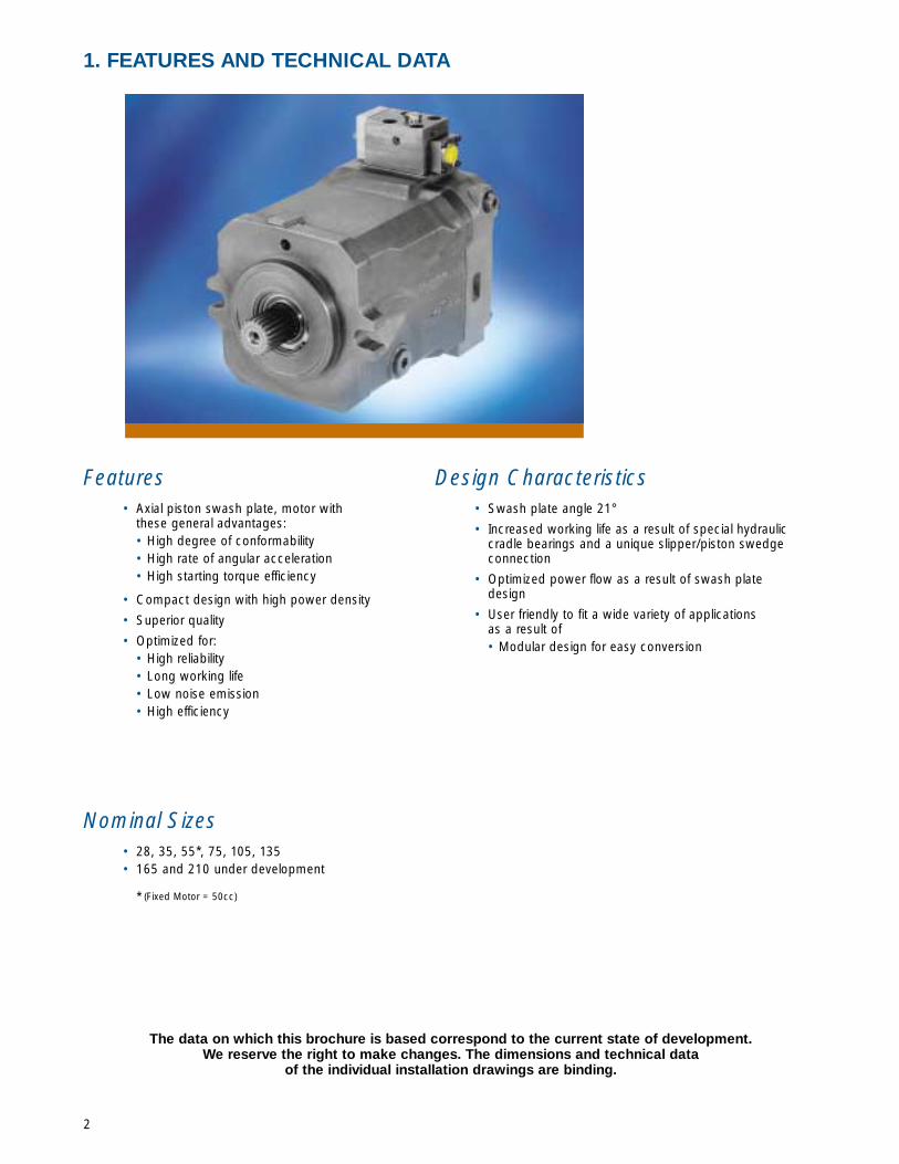
Features• Axial piston swash plate, motor with
these general advantages:• High degree of conformability• High rate of angular acceleration• High starting torque efficiency
• Compact design with high power density
• Superior quality
• Optimized for:• High reliability • Long working life • Low noise emission • High efficiency
Nominal Sizes• 28, 35, 55*, 75, 105, 135• 165 and 210 under development
* (Fixed Motor = 50cc)
Design Characteristics• Swash plate angle 21°
• Increased working life as a result of special hydrauliccradle bearings and a unique slipper/piston swedgeconnection
• Optimized power flow as a result of swash platedesign
• User friendly to fit a wide variety of applicationsas a result of • Modular design for easy conversion
1. FEATURES AND TECHNICAL DATA
2
The data on which this brochure is based correspond to the current state of development.We reserve the right to make changes. The dimensions and technical data
of the individual installation drawings are binding.
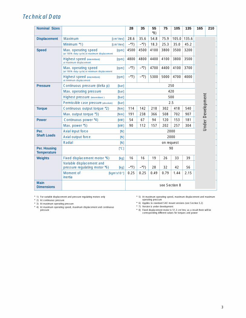
Technical Data
3
* 5) At maximum operating speed, maximum displacement and maximumoperating pressure
* 6) Applies to standard SAE mount versions (see Section 5.2)* 7) Version is under development* 8) Fixed displacement motor is 51.3 cm3/rev; as a result there will be
corresponding different values for torques and power
* 1) For variable displacement and pressure regulating motors only* 2) At continuous pressure* 3) At maximum operating pressure* 4) At maximum operating speed, maximum displacement and continuous
pressure
Und
er D
evel
opm
ent
Nominal Sizes 28 35 55 75 105 135 165 210*8)
Displacement Maximum [cm3/rev] 28.6 35.6 54.8 75.9 105.0 135.6
Minimum *1) [cm3/rev] –*7) –*7) 18.3 25.3 35.0 45.2
Speed Max. operating speed [rpm] 4500 4500 4100 3800 3500 3200(at 100% duty cycle) at maximum displacement
Highest speed (intermittent) [rpm] 4800 4800 4400 4100 3800 3500at maximum displacement
Max. operating speed [rpm] –*7) –*7) 4700 4400 4100 3700(at 100% duty cycle) at minimum displacement
Highest speed (intermittent) [rpm] –*7) –*7) 5300 5000 4700 4000at minimum displacement
Pressure Continuous pressure (delta p) [bar] 250
Max. operating pressure [bar] 420
Highest pressure (intermittent ) [bar] 500
Permissible case pressure (absolute) [bar] 2.5
Torque Continuous output torque *2) [Nm] 114 142 218 302 418 540
Max. output torque *3) [Nm] 191 238 366 508 702 907
Power Continuous power *4) [kW] 54 67 94 120 153 181
Max. power *5) [kW] 90 112 157 202 257 304
Per. Axial input force [N] 2000Shaft Loads Axial output force [N] 2000
Radial [N] on request
Per. Housing [°C] 90Temperature
Weights Fixed displacement motor *6) [kg] 16 16 19 26 33 39Variable displacement andpressure regulating motor *6) [kg] –*7) –*7) 28 32 42 56
Moment of [kgm2x10-2] 0.25 0.25 0.49 0.79 1.44 2.15inertia
Mainsee Section 8Dimensions

Two porting options and a variety of equipmentoptions are available for this motor (see Section 5and 6) to ensure the best possible adaptationto your specific application.
The use of dual pressure crossover relief valvesbroadens the spectrum of possible applications.The low setting of the relief valve permits softgentle braking of the motor. When the relief valve istriggered to its high setting, maximum accelerationand braking torque is available at the motor. Atypical application of this type is a turning andboring mill drive.
Fixed displacement motor (standard version)
Details: (top picture) Fully adjustablepilot operating crossover relief valves.(lower picture) Dual pressure pilotoperated crossover relief valves.
Motor with purge valves Motor with crossover reliefvalves with fixed settings
Motor with dual pressurecrossover relief valves
2. HMF-02 FIXED DISPLACEMENT MOTORS
Fixed displacement motors of the HMF-02 typeare suitable for both open and closed loop circuit
4
E Anti-cav connectionX, Y Control connections for dual pressure
crossover relief valve
A, B Working port connectionsL, L1, U Case drain, vent connections
0 Pilot signal maxPressure setting of the
dual pressure relief valve
min
max
Hig
h pr
essu
re
3.1 Two-position control (flip-flop)3. HMV-02 TWO-POSITION MOTORS
Circuit Diagram and Adjustment Characteristics
Technical Data
5
A, B Work ports connection
L, U Case drain/ventconnections
E Servo supplypressure connection
X Control connection
Two-position motor with hydraulic controlpressure and external servo supply pressure
The values listed beloware applicable for all
nominal sizes
20
40
20
40
Hirschmann
12 24
Direct current≤ 26
100
IP 6K6K, Part 9
0.5
*1) connection E in the circuit diagram shown below *2) connection X in the circuit diagram shown below
*3) other connector versions on request *4) other response times are possible by using special nozzles
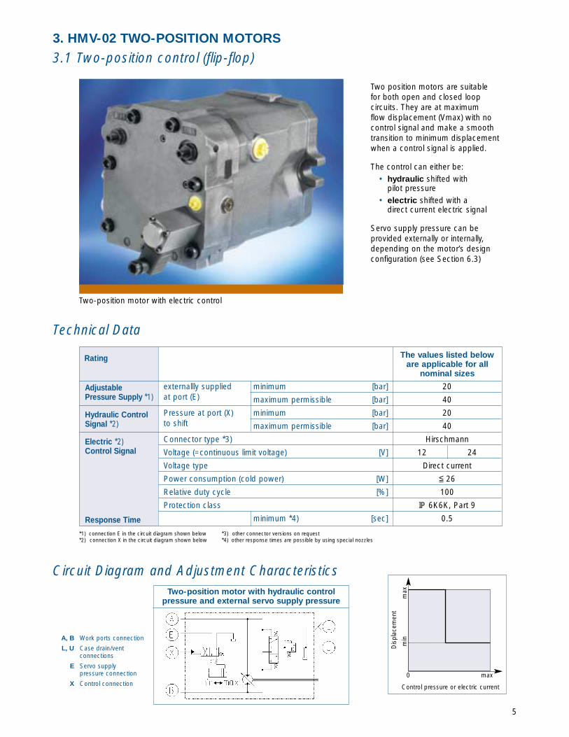
Two position motors are suitablefor both open and closed loopcircuits. They are at maximumflow displacement (Vmax) with nocontrol signal and make a smoothtransition to minimum displacementwhen a control signal is applied.
The control can either be:• hydraulic shifted with
pilot pressure • electric shifted with a
direct current electric signal
Servo supply pressure can beprovided externally or internally,depending on the motor’s designconfiguration (see Section 6.3)
Two-position motor with electric control
0 max
Control pressure or electric current
min
max
Dis
plac
emen
texternallly supplied minimum [bar]at port (E) maximum permissible [bar]
Pressure at port (X) minimum [bar]to shift maximum permissible [bar]
Connector type *3)
Voltage (=continuous limit voltage) [V]
Voltage type
Power consumption (cold power) [W]
Relative duty cycle [%]
Protection class
minimum *4) [sec]
Adjustable Pressure Supply *1)
Hydraulic ControlSignal *2)
Electric *2)Control Signal
Response Time
Rating
Ext. servo supplypressure *1)Hydraulic controlsignalsElectric controlsignals *2)
Response time
2040
8 to 1440
Hirschmann12 24
Direct current15.6
1300450 225
1200 600100
IP 6K6K, Part 90.5
RatingThe values listed below areapplicable for all rated sizes
minimal [bar]maximum permissible [bar]Control range [bar]maximum permissible pressure [bar]Connector type *3) Nominal voltage (=continuous limit voltage) [V]Voltage typePower consumption [W]Nominal current (=continuous limit current) [mA]Control current Swash begin [mA]
Swash end [mA]Relative duty cycle [%]Protection classminimum *4) [sec]
3.2 HMV-02 Infinitely Variable Control
6
Circuit Diagram and Adjustment Characteristics
Technical Data
A, B Work portconnections
L, U Case drain/ventconnections
E Servo supplypressure connection
Mx Control solenoid
Infinitely variable motor with electric displacementcontrol and external servo supply pressure
*1) connection E in the circuit diagram shown below *2) connection Mx in the circuit diagram shown below
*3) other connector versions on request *4) other response times are possible by using special orifices
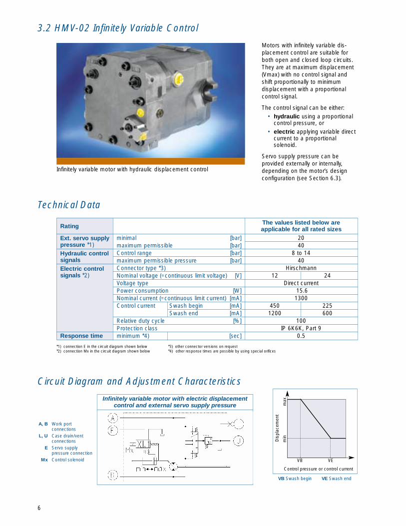
Motors with infinitely variable dis-placement control are suitable forboth open and closed loop circuits.They are at maximum displacement(Vmax) with no control signal andshift proportionally to minimumdisplacement with a proportionalcontrol signal.
The control signal can be either: • hydraulic using a proportional
control pressure, or • electric applying variable direct
current to a proportionalsolenoid.
Servo supply pressure can beprovided externally or internally,depending on the motor’s designconfiguration (see Section 6.3).
Infinitely variable motor with hydraulic displacement control
VB VE
Control pressure or control current
min
max
Dis
plac
emen
t
VB Swash begin VE Swash end

7
3.3 HMV-02 Infinitely Variable Control with Pressure Override
Circuit Diagram and Adjustment/Control Characteristics
Technical Data
Infinitely variable displacement control motor withpressure override, electric maximum displacement
override, and brake pressure shut off.
Control range [bar]
Maximum permissible pressure [bar]
Start of pressure RB *2) [bar]
End of pressure RE [bar]
All electrical data *4)
Minimum *3) [sec]
Hydraulic controlsignal *1)
Hydraulicpressure override
Switching magnet
Response time
Rating The values listed beloware applicable for
all rated sizes
8 to 14
40
190 - 260
5% above start of pressure
See table on page 5
0.5
*1) connection X in the circuit diagram shown below*2) adjustable, please indicate when ordering (see Section 7.3)
*3) other response times are possible by using special orifices*4) other control options are available to control DOR and BPS. (see Section 6.2, page 10)
This motor is used primarily inclosed loop circuits.
It is at maximum displacement(Vmax) with no control signal.Variable displacement control tolower displacement is accomplishedhydraulically with the application ofa proportional control pressuresignal by the operator.
The motor is also equipped witha system pressure override (POR)which increases the motor’sdisplacement in response to system-related demands for torque whena predefined system pressuresetting is reached, overridingthe operator’s command forlower displacement.
Variable motor with pressure override
In addition, this motor has • electric maximum displacement override (DOR)
that makes it possible to shift the motor to itsmaximum displacement independently of thecontrol pressure, and to lock it there, (as withthe fixed displacement motor.
• electric brake pressure shut off (BPS). It preventsabrupt reactions and response by the systempressure override control to dynamic brakingpressures, and thus makes it possible for amore controlled deceleration of the vehicle.
VB Swash beginVE Swash end
RB Start of pressure overrideRE End of pressure override
VB VE maxControl Pressure
min
max
Dis
plac
emen
t
0
RB RE max0
Operating Pressure
A, B Working port
L, U Case drain/vent connections
X Pressure connection forinfinitely variable control
M1 Solenoid for maximum displacement override
M2 Solenoid for brakepressure shut off

4. HMR-02 Pressure Regulating Motors
8
Pressure regulating motor with electric maximum dis-placement override and cross over relief valve protection
Pressure regulating motor with electric maximumdisplacement override and brake pressure shut off.
Circuit Diagram and Control Characteristics
Technical Data
A, B Works portconnections
L, U Case drain/ventconnections
M1 Solenoid for maximumdisplacement overrideregulation
X, Y Gauge ports
Pressure regulating motor with electricmaximum displacement override
Regulation begin (RB) *1) [bar]
Regulation end (RE) [bar]
Shifting pressure min/max [bar]
Shifting pressure min/max [bar]
Shifting pressure min/max [bar]
All electrical data
Pressure regulating control
Pneumatic max. displ. override
Hydraulic pilot pressure max. displ. override
Hydraulic high-pressure max. displ. override
Electric max. displ. override
Electric brake pressure shut off *2)
Rating The values listed beloware applicable forall nominal sizes
190 to 260
5% above regulation begin (RB)
4 to 8
20 to 30
30 to 420
See table page 5
*1) adjustable, please indicate when ordering (see Section 7.4) *2) other options are available for brake pressure shut off. (see Section 6.2)
Linde pressure regulating motors are suitable for bothopen and closed loop circuits. They are high-pressurecontrolled, and are at minimum displacement (Vmin)when system pressure is below the pressure regulationset point of regulation begin (RB). When the pressureregulation set point is reached, the motor smoothlyincreases displacement in response to system-dependent demands for torque. The additionalmaximum displacement override control makes itpossible to shift the motor to maximum displacementindependently of the pressure regulating control, andlocks it there as with a fixed displacement motor.
The maximum displacement override signal can beeither:
• pneumatic shifted with a low pressure air signal • hydraulic shift with a hydraulic pressure signal • electric shift with a direct current electric signal.
The typical configuration of pressure regulating motorsfor use in open or closed loop circuits is as follows:• Open loop circuit: with cross over relief valve pro-
tection and counter balance valve (see Section 6.7)• Closed loop circuit: with electric brake
pressure shut off (see Section 6.6)
RB Regulation Begin RE Regulation End
RB RE max
Operating Pressure
min
0
max
max
Dis
plac
emen
t
0
Driv
e To
rque

Suitability and availability for motor types
SAE flange *1)
Plug-in *1) *2)
✓ ✓ ✓ ✓ ✓
✓ ✓ ✓ ✓ ✓ ✓ ✓
9
5. DESIGN CONFIGURATIONS
5.1 Arrangement of the High-Pressure Ports
Depending on the installation situation andaccessibility, optional rear or side high-pressure portsare available. SAE flange mounts or plug in style are
also available. The following tables show the suitabilityand availability.
Suitability and availability for motor types
Side
Rear *1)
Fixeddispl. motor
Variabledispl. motor
Var displ. motor +override control
Pressureregulating motor
open closed open closed closed open closed
Fixeddispl. motor
Variabledispl. motor
Var displ. motor +override control
Pressureregulating motor
open closed open closed closed open closed
✓ ✓ ✓ ✓ ✓ ✓ ✓
✓ ✓ ✓ ✓ ✓ ✓ ✓
*1) selected sizes available
Input Flow vs. Shaft Output Rotation
Identification of Ports
Shaft Output Direction of Rotation
Motor Type Input Flow Into Port
HMF-02 A B
HMR-02 B A
HMV-02 B A
5.2 Mounting Versions
*1) see Section 8.5 for dimensions *2) selected sizes available (see Section 8.5)
Circuit loopPicture
Figure 9
Figure 10
Circuit loopPicture
Picture 19
Picture 20
presentlyreversed
left to right
10
Suitability and availability for motor types
Hydraulictwo position
Electrictwo position
Hydraulicproportional
Electricalproportional12 v or 24 V
Fixeddispl. motor
Variabledispl. motor
Var. displ. motor+ override control
Pressureregulating motor
open closed closed
Fixeddispl. motor
Variabledispl. motor
Var. displ. motor+ override control
Pressureregulating motor
open closedclosed
✓
✓
✓
✓
✓
✓
✓
✓
-
-
✓
-
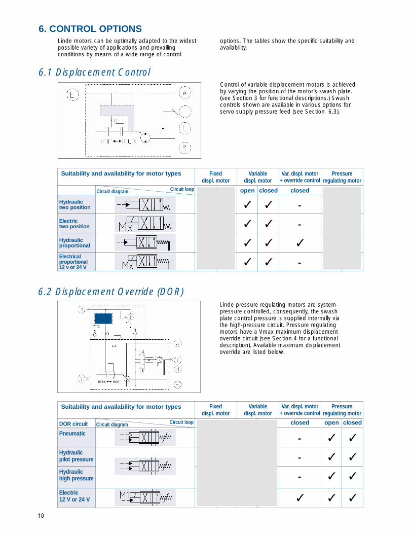
6.1 Displacement Control
Linde motors can be optimally adapted to the widestpossible variety of applications and prevailingconditions by means of a wide range of control
options. The tables show the specific suitability andavailability.
6. CONTROL OPTIONS
Control of variable displacement motors is achievedby varying the position of the motor’s swash plate.(see Section 3 for functional descriptions.) Swashcontrols shown are available in various options forservo supply pressure feed (see Section 6.3).
Suitability and availability for motor types
Pneumatic
DOR circuit
Hydraulicpilot pressure
Hydraulichigh pressure
Electric12 V or 24 V
-
-
-
✓ ✓ ✓
✓ ✓
✓ ✓
✓ ✓
6.2 Displacement Override (DOR)Linde pressure regulating motors are system-pressure controlled, consequently, the swashplate control pressure is supplied internally viathe high-pressure circuit. Pressure regulatingmotors have a Vmax maximum displacementoverride circuit (see Section 4 for a functionaldescription). Available maximum displacementoverride are listed below.
Circuit loopCircuit diagram
Circuit loopCircuit diagram
max min
11
Suitability and availability for motor types
Externalsupply
Internalsupply fromthe high-pressurecircuit
- ✓ - - -
- ✓ ✓ - -
✓ - - ✓ ✓
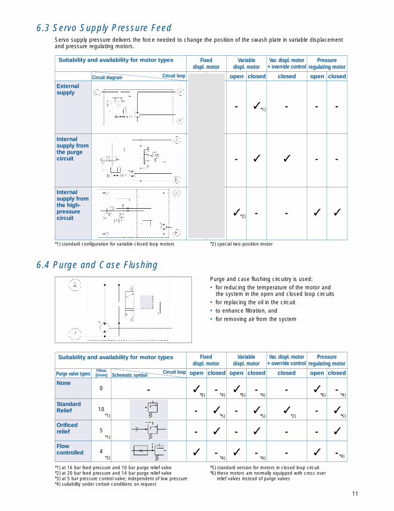
6.3 Servo Supply Pressure FeedServo supply pressure delivers the force needed to change the position of the swash plate in variable displacementand pressure regulating motors.
None
StandardRelief
Orificedrelief
Flowcontrolled
Purge valve typesFlfow[l/min]
- ✓ -✓ -✓-0
10
5
4
-
6.4 Purge and Case FlushingPurge and case flushing circuitry is used:• for reducing the temperature of the motor and
the system in the open and closed loop circuits • for replacing the oil in the circuit • to enhance filtration, and• for removing air from the system
*1)
*2)
Internalsupply fromthe purgecircuit
*1) standard configuration for variable closed loop motors *2) special two-position motor
*1) at 16 bar feed pressure and 10 bar purge relief valve*2) at 20 bar feed pressure and 14 bar purge relief valve*3) at 5 bar pressure control valve; independent of low pressure*4) suitability under certain conditions on request
*5) standard version for motors in closed loop circuit*6) these motors are normally equipped with cross over
relief valves instead of purge valves
*6) *4) *6) *4) *4)*6)
✓ - ✓- ✓- ✓*5) *5) *5)*2)
- - ✓- ✓- ✓
- ✓ -✓ -✓ -*4) *4) *4)
*1)
*1)
*3)
Fixeddispl. motor
Variabledispl. motor
Var. displ. motor+ override control
Pressureregulating motor
open closed open closedclosedCircuit loopCircuit diagram
Suitability and availability for motor types Fixeddispl. motor
Variabledispl. motor
Var. displ. motor+ override control
Pressureregulating motor
open closedopen closed open closedclosedCircuit loopSchematic symbol
12
Withoutcrossoverrelief valve
Withcrossoverrelief valveprotection *1)
With dualpressurerelief valveprotection*2)
✓ ✓ ✓ ✓ ✓ ✓ ✓
✓ ✓ - - - ✓ ✓
✓ - - - - - -
*1)
*1)
*1)
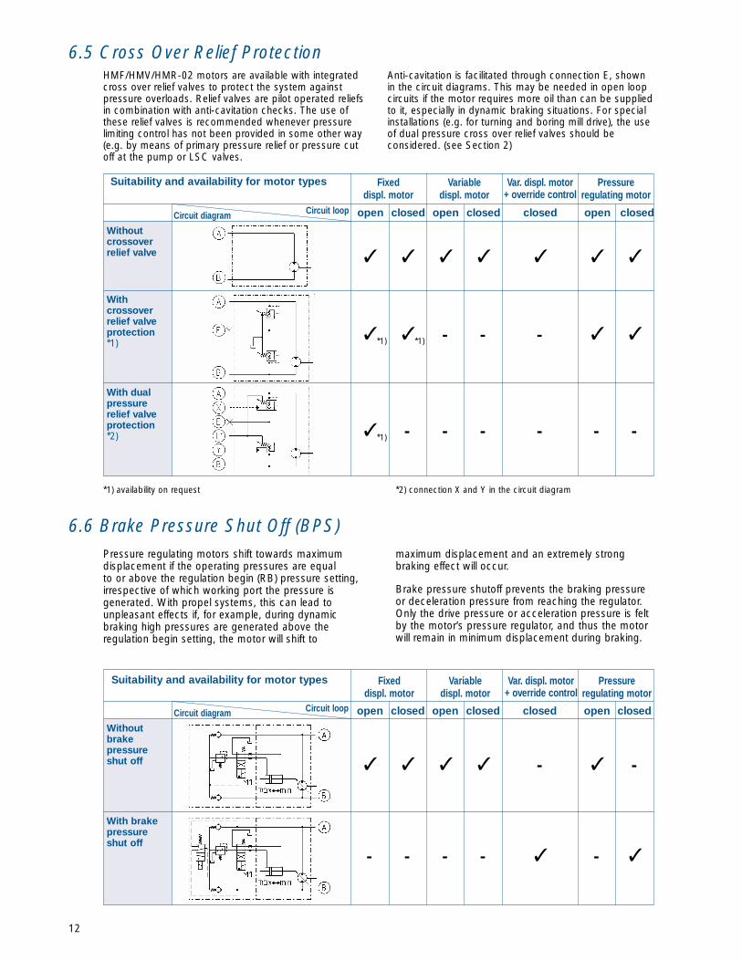
6.6 Brake Pressure Shut Off (BPS)Pressure regulating motors shift towards maximumdisplacement if the operating pressures are equalto or above the regulation begin (RB) pressure setting,irrespective of which working port the pressure isgenerated. With propel systems, this can lead tounpleasant effects if, for example, during dynamicbraking high pressures are generated above theregulation begin setting, the motor will shift to
maximum displacement and an extremely strongbraking effect will occur.
Brake pressure shutoff prevents the braking pressureor deceleration pressure from reaching the regulator.Only the drive pressure or acceleration pressure is feltby the motor’s pressure regulator, and thus the motorwill remain in minimum displacement during braking.
Withoutbrakepressureshut off
With brakepressureshut off
✓ ✓ ✓ ✓ - ✓ -
- - - - ✓ - ✓
*1) availability on request *2) connection X and Y in the circuit diagram
6.5 Cross Over Relief ProtectionHMF/HMV/HMR-02 motors are available with integratedcross over relief valves to protect the system againstpressure overloads. Relief valves are pilot operated reliefsin combination with anti-cavitation checks. The use ofthese relief valves is recommended whenever pressurelimiting control has not been provided in some other way(e.g. by means of primary pressure relief or pressure cutoff at the pump or LSC valves.
Anti-cavitation is facilitated through connection E, shownin the circuit diagrams. This may be needed in open loopcircuits if the motor requires more oil than can be suppliedto it, especially in dynamic braking situations. For specialinstallations (e.g. for turning and boring mill drive), the useof dual pressure cross over relief valves should beconsidered. (see Section 2)
Suitability and availability for motor types Fixeddispl. motor
Variabledispl. motor
Var. displ. motor+ override control
Pressureregulating motor
open closedopen closed open closedclosedCircuit loopCircuit diagram
Suitability and availability for motor types Fixeddispl. motor
Variabledispl. motor
Var. displ. motor+ override control
Pressureregulating motor
open closedopen closed open closedclosedCircuit loopCircuit diagram

13
*1) the rear mount is shown; side mount is also possible.
*1) Illustration is one example, other versions are available. Please consult factory for availability and technical data.
6.7 Counter BalanceThe counter balance valve prevents over speedingthe motor during an over running condition. Toachieve this, the motor’s exhaust oil is automaticallymetered to restrict its escape. With integratedanti-cavitation circuitry, cavitation can be prevented.
In addition, a flushing valve can be incorporated to allowmotor case flushing.Counter balance valves are typically used in drivesystems in open loop circuits.
Withoutcounter-balance
Withcounter-balancevalve*1)
✓✓✓
✓-
✓
---✓
✓✓✓
-
6.8 Speed SensorMotors can be equipped with speed sensors.Please consult factory as not all models and sizesare currently adapted for this option. Speed sensors
detect the motor speed electronically and supply itto an electronic control device in the form of aninput signal.
Withoutspeedsensor
Withspeedsensor*1)
✓ ✓ ✓ ✓ ✓ ✓ ✓
✓ ✓ ✓ ✓ - ✓ ✓
Suitability and availability for motor types Fixeddispl. motor
Variabledispl. motor
Var. displ. motor+ override control
Pressureregulating motor
open closedopen closed open closedclosedCircuit loopPhoto
Suitability and availability for motor types Fixeddisplacement
motor
Variabledisplacement
motor
Variable displ. motor +
override control
Pressureregulating
motor
open closedopen closed open closedclosedCircuit loopCircuit diagram
Figure 26
Figure 27
Figure 7
Figure 8

14
Model Codes for H-Series-02 Fixed Displacment Motors1 2 3 4 5 6 7
DISPLACEMENT FLUSHING MOUNTING SHAFT CROSSOVER RELIEF ADD-ONS SPECIAL(cc/rev) VALVE VALVE, SETTINGrrr r r r rrr rr r
75 C C C 250 AR X
MODEL
HMFH-SeriesFixed MotorEXAMPLE:
1 DISPLACEMENT SIZE
28 (1.71 cir)35 (2.12 cir)50 (3.05 cir)75 (4.57 cir)
105 (6.40 cir)135 (8.24 cir)
2 FLUSHING
C = CLOSED LOOPO= OPEN LOOPP = PLAINB = BLOCKEDNote: With integrated COR’s
motors are P.
3 MOUNTING
B = SAE B 2 BOLT (28,35)C = SAE C 2 BOLT (50, 75, 105)D= SAE D 2 BOLT (135)
7 SPECIALS (2)
INSERT S, THEN CALL OUTREQUIREMENT IN CLEAR TEXT
6 ADD-ONS
Port OrientationA = SIDE PORTSB = REAR PORTS (4)Additional Valves:C = CBVR= CORV = DUAL PRESSURE R/V’S (3)
5 COR VALVE SETTING (3)
CALL OUT SETTING IN BAR1 BAR = 14.5 PSI
6 SHAFT
J = SAE BB (35)C = SAE C (50, 75)H= ANSI 16.32, 21T (50,75)
ANSI 16.32, 23T (105)ANSI 16.32, 27T (135)
D= SAE D 13T (135)
NOTES: (1) If codes are not used, insert the letter “X”(2) If a unit is a special execution, insert “S” at the end of the code description(3) Specify lower setting in bar in position 5, then call out in clear text higher setting.(4) Side ports are standard. End ports are not normally available. Consult factory.

15
Model Codes for H-Series-02 Regulated Motors1 2 3 4 5 6 7 8 9 10 11
DISPLACEMENT FLUSHING CONTROL CONTROL MOUNTING SHAFT RB DISP. DISP. ADD-ONS SPECIALS(cc/rev) VALVE OPTIONS MAXIMUM MINIMUMrrr r r r rrr rr rrr rrr rr rrr r
135 P R B D H 260 X 41 BRN S
1 DISPLACEMENT (CC/REV)
75 (4.63 cir)105 (6.41 cir)135 (8.27 cir)
2 FLUSHING
C = CLOSED LOOPO= OPEN LOOPP = PLAINB = BLOCKEDNote: With integral COR’s
motors are P.
3 CONTROL
R= SYSTEM PRESSUREREGULATED (STD)
2 = REGULATOR SET UP FORTWO POSITION CONTROL(default is max; shift to min.)
Z = REGULATOR SET UP FORTWO POSITION CONTROL(default is min; shift to max.)
4 CONTROL OPTIONS
B = BI-DIRECTIONAL REGULATORSHUTTLE (STD)
U= UNI-DIRECTIONAL (3)N= NONE (Ext. fed to regulator)
5 MOUNTING
C = SAE C 2 BOLT MTG (75, 105)D= SAE D 2 BOLT MTG (135)S = SPECIAL PLUG IN MOUNT
(105, 135)
6 SHAFT
H= ANSI 21T 16/32 P (75)ANSI 23T 16/32 P (105)ANSI 27T 16/32 P (135)
C = SAE C 14T 12/24 P(OPT 75, 105)
D= SAE E 13T 8/16 P(OPT 75, 105)
7 REGULATION BEGIN
SPECIFY SETTING IN BAR1 BAR = 14.5 PSI
11 SPECIALS (2)
INSERT S, THEN CALL OUTREQUIREMENT IN CLEAR TEXT
10 ADD-ONS
Port OrientationA = SIDE PORTSB = REAR PORTS (4)Additional Valves:A = BRAKE CBV ON “A” PORTB = BRAKE CBV ON “B” PORTC = CLOSED CENTER CBV (1)O= ORIFICED CENTER CBV (1)R= COR (NO CBV) (1)X = NONEDor Options:D= PILOT PRESS DORH= SYSTEM PRESS DORE = ELECT DOR w/BPS (2)F = ELECT DOR w/o BPS (2)N= PNEUM. DORX = NONENOTE: Check with factory foravailability of add-on optionsfor desired unit size.
9 MIN. DISPLACEMENT)
SPECIFY SETTING IN CC/REV22 = MIN. DISPL. FOR 7531 = MIN. DISPL. FOR 10541 = MIN. DISPL. FOR 135
8 MAX. DISPLACEMENT
IF NOT DESTROKED, ENTER X.OTHERWISE, SPECITY SETTINGIN CC/REV.
MODEL
HMREXAMPLE:
NOTES: (1) If motor has COR _____, enter “S” in column 1 and specify relief valve setting in bar.(2) Enter “S” in column 11 and specify either 12 or 24 VDC solenoids.
Reference: BPS = Brake Pressure Shut-off.(3) Enter “S” in column 11 and specify which pressure port should feed regulator.
(A or B, see installation drawings).
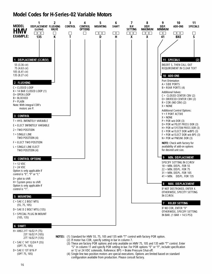
Model Codes for H-Series-02 Variable Motors1 2 3 4 5 6 7 8 9 10 11
DISPLACEMENT FLUSHING CONTROL CONTROL MOUNTING SHAFT R/V DISP. DISP. ADD-ONS SPECIALS(cc/rev) VALVE OPTIONS SETTING MAXIMUM MINIMUMrrr r r r rrr rr rrr rrr rr rrr r
135 K T D H X X 41 BXE S
1 DISPLACEMENT (CC/REV)
55 (3.36 cir)75 (4.63 cir)
105 (6.41 cir)135 (8.27 cir)
2 FLUSHING
C = CLOSED LOOPK = 14 BAR CLOSED LOOP (1)O= OPEN LOOPB = BLOCKEDP = PLAINNote: With integral COR’s
motors are P.
3 CONTROL
T = HYD. INFINITELY VARIABLEE = ELECT INFINITELY VARIABLE2 = TWO POSITION1 = SINGLE LINE
TWO POSITION (4)F = ELECT TWO POSITIONL = SINGLE LINE ELECT
TWO POSITION (4)
4 CONTROL OPTIONS
1 = 12 VDC2 = 24 VDCOption is only applicable ifcontrol is “E”, “F” or “L”D= pilot to shiftH= System press to shiftOption is only applicable ifcontrol is “1”.
5 MOUNTING
C = SAE C 2 BOLT MTG(55, 75, 105)
D= SAE D 2 BOLT MTG (135)S = SPECIAL PLUG IN MOUNT
(105, 135)
6 SHAFT
H= ANSI 21T 16/32 P (75)ANSI 23T 16/32 P (105)ANSI 27T 16/32 P (135)
C = SAE C 14T 12/24 P (55)(OPT 75, 105)
D= SAE E 13T 8/16 P(OPT 75, 105)
11 SPECIALS (2)
INSERT S, THEN CALL OUTREQUIREMENT IN CLEAR TEXT
10 ADD-ONS
Port OrientationA = SIDE PORTSB = REAR PORTS (4)Additional Valves:C = CLOSED CENTER CBV (2)O= ORIFICED CENTER CBV (2)R= COR (NO CBV) (2)X = NONEAdditional Control Options:Y = F PORT ACTIVEX = NONEP = POR w/o DOR (3)D= POR w/ PILOT PRESS DOR (3)H= POR w/ SYSTEM PRESS DOR (3)E = POR w/ ELECT DOR w/BPS (3)F = POR w/ ELECT DOR w/o BPS (3)N = POR w/ PNEUM. DOR (3)
NOTE: Check with factory foravailability of add-on optionsfor desired unit size.
9 MIN. DISPLACEMENT
SPECIFY SETTING IN CC/REV18 = MIN. DISPL. FOR 5522 = MIN. DISPL. FOR 7531 = MIN. DISPL. FOR 10541 = MIN. DISPL. FOR 135
8 MAX. DISPLACEMENT
IF NOT DESTROKED, ENTER X.OTHERWISE, SPECITY SETTINGIN CC/REV.
7 RELIEF SETTING
IF NO COR, ENTER “X”OTHERWISE, SPECIFY SETTINGIN BAR. (1 BAR = 14.5 PSI)
MODEL
HMVEXAMPLE:
NOTES: (1) Standard for HMV 55, 75, 105 and 135 with “T” control with factory POR option.(2) If motor has COR, specify setting in bar in column 7.(3) These are factory POR options and only available on HMV 75, 105 and 135 with “T” control. Enter
“S” in column 11 and specify POR setting in bar. For POR options “E” or “F”, include specificationor 12 or 24 VDC solenoids. Reference: BPS = Brake Pressure Shut-off.
(4) Single line two position motors are special executions. Options are limited based on standardconfiguration available from production. Please consult factory.
16
All metric threaded connections per DIN 3852Threaded connections per ISO 6149 on request.
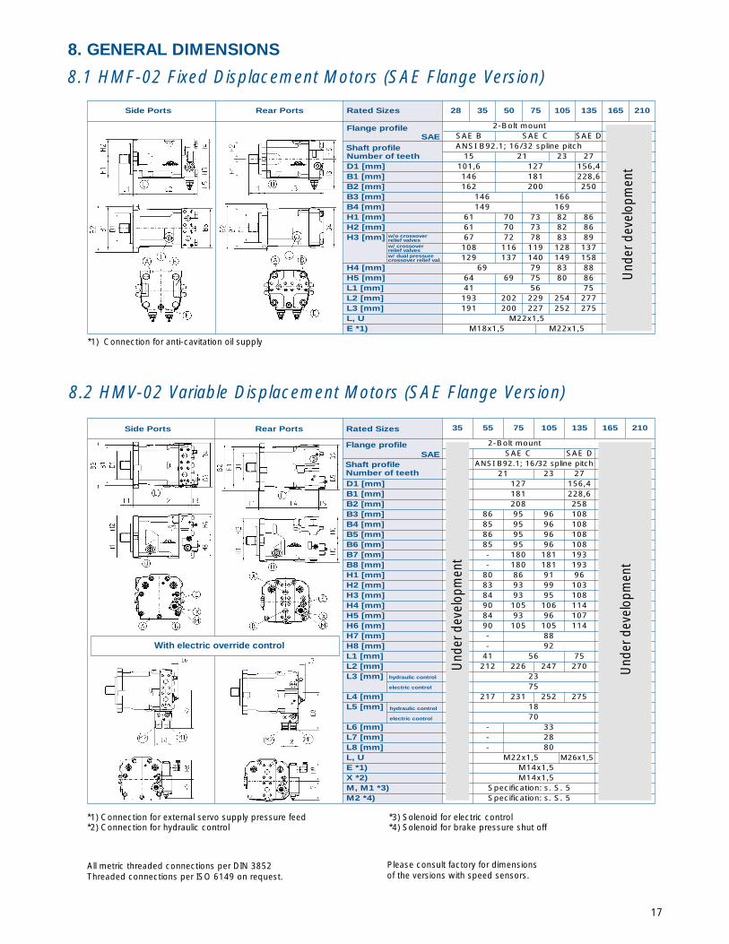
35 55 75 105 135 165 210
2-Bolt mountSAE C SAE D
ANSI B92.1; 16/32 spline pitch21 23 27
D1 [mm] 127 156,4B1 [mm] 181 228,6B2 [mm] 208 258B3 [mm] 86 95 96 108B4 [mm] 85 95 96 108B5 [mm] 86 95 96 108B6 [mm] 85 95 96 108B7 [mm] - 180 181 193B8 [mm] - 180 181 193H1 [mm] 80 86 91 96H2 [mm] 83 93 99 103H3 [mm] 84 93 95 108H4 [mm] 90 105 106 114H5 [mm] 84 93 96 107H6 [mm] 90 105 105 114H7 [mm] - 88H8 [mm] - 92L1 [mm] 41 56 75L2 [mm] 212 226 247 270L3 [mm] hydraulic control 23
electric control 75L4 [mm] 217 231 252 275L5 [mm] 18
70L6 [mm] - 33L7 [mm] - 28L8 [mm] - 80L, U M22x1,5 M26x1,5E *1) M14x1,5X *2) M14x1,5M, M1 *3) Specification: s. S. 5M2 *4) Specification: s. S. 5
*1) Connection for external servo supply pressure feed*2) Connection for hydraulic control
*3) Solenoid for electric control*4) Solenoid for brake pressure shut off
With electric override control
Und
er d
evel
opm
ent
Side Ports Rear Ports Rated Sizes
Flange profile
Shaft profileNumber of teeth
Und
er d
evel
opm
ent
SAE
hydraulic control
electric control
Please consult factory for dimensionsof the versions with speed sensors.
17
8.1 HMF-02 Fixed Displacement Motors (SAE Flange Version)
8. GENERAL DIMENSIONS
8.2 HMV-02 Variable Displacement Motors (SAE Flange Version)
*1) Connection for anti-cavitation oil supply
Und
er d
evel
opm
ent
Side Ports Rear Ports Rated Sizes 28 35 50 75 105 135 165 210
Flange profile 2-Bolt mountSAE B SAE C SAE D
Shaft profile ANSI B92.1; 16/32 spline pitchNumber of teeth 15 21 23 27D1 [mm] 101,6 127 156,4B1 [mm] 146 181 228,6B2 [mm] 162 200 250B3 [mm] 146 166B4 [mm] 149 169H1 [mm] 61 70 73 82 86H2 [mm] 61 70 73 82 86H3 [mm] w/o crossover
67 72 78 83 89108 116 119 128 137129 137 140 149 158
H4 [mm] 69 79 83 88H5 [mm] 64 69 75 80 86L1 [mm] 41 56 75L2 [mm] 193 202 229 254 277L3 [mm] 191 200 227 252 275L, U M22x1,5E *1) M18x1,5 M22x1,5
relief valves
w/ crossover
relief valves
w/ dual pressure crossover relief val.
SAE

18
All metric threaded connections per DIN 3852.Threaded connections per ISO 6149 on request.
Please consult factory for dimensions of the versions with speed sensors.
8.3. HMR-02 Pressure Regulating Motors (SAE Flange Version)
with Counter Balance Valve
Und
er d
evel
opm
ent
Und
er d
evel
opm
ent
Side Ports Rear Ports Rated Sizes 35 55 75 105 135 165 210
Flange profile 2-Bolt mountSAE C SAE D
Shaft profile ANSI B92.1; 16/32 spline pitch
Number of teeth 21 23 27D1 [mm] 127 156,4B1 [mm] 181 228,6B2 [mm] 208 258B3 [mm] without/with
secondaryrelief valve
95 99 108135 136 140
B4 [mm] 95 105 108102 105 114
B5 [mm] 95 99 108135 139 141
B6 [mm] 102 105 114B7 [mm] pneumatic 74
hydraulic 62B8 [mm] 78B9 [mm] 103B10 [mm] 89B11 [mm] 130H1 [mm] 86 91 96H2 [mm] 93 99 100H3 [mm] 93 98 108H4 [mm] 102 102 110H5 [mm] 56H6 [mm] 91 96 107H7 [mm] 102 102 109H8 [mm] 81H9 [mm] 85L1 [mm] 56 75L2 [mm] 229 247 270L3 [mm] 231 252 275L4 [mm] 53L5 [mm] *4) 80L6 [mm] 127L, U M22x1,5X1 *1) M14x1,5M1 *2) Specification: see pg. 5 M2 *3)
8.4. Plug-in Motors
*1) Connection for hydraulic or pneumatic maximum displacement override*2) Solenoid magnet for electric maximum displacement override
*3) Solenoid magnet for brake pressure shut off*4) Regulator with electric maximum displacement
override and brake pressure shut off
*1) Some of the dimensions in Sections 8.1through 8.3 may be applicable
*2) Size 75 has a 2-bolt SAE flange.
8.5. High-Pressure Connections
*1) 17 mm deep, 8 places
Und
erD
evel
op-
men
t
Und
erde
velo
pmen
t
Rated sizes 28 35 55 75 105 135 165 210
F1 [mm] 50,8 57,2F2 [mm] 74 84F3 [mm] 23,8 27,8A, B 3/4" 1"S *1) M10 M12
Variable displacement motor *1) Rated sizes 35 55 75 105 135 165 210
D1 [mm] 190 216D2 [mm] 251 282F1 [mm] - *2) 55,8F2 [mm] 0 *2) 223,4F3 [mm] - *2) 129F4 [mm] 224 *2) 251,8L1 [mm] 143 169L2 [mm] 124 132 175
SAE
without/withsecondaryrelief valvewithout/withsecondaryrelief valve
Specification: see pg. 5
Und
erde
velo
pmen
t
19
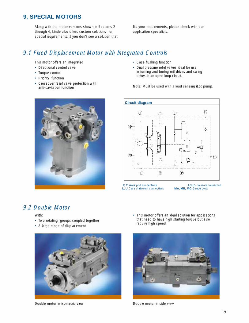
9. SPECIAL MOTORS
Along with the motor versions shown in Sections 2through 4, Linde also offers custom solutions forspecial requirements. If you don’t see a solution that
fits your requirements, please check with ourapplication specialists.
This motor offers an integrated • Directional control valve• Torque control• Priority function• Crossover relief valve protection with
anti-cavitation function
• Case flushing function• Dual pressure relief valves ideal for use
in turning and boring mill drives and swingdrives in an open loop circuit.
Note: Must be used with a load sensing (LS) pump.
With: • Two rotating groups coupled together• A large range of displacement
• This motor offers an ideal solution for applicationsthat need to have high starting torque but alsorequire high speed
9.1 Fixed Displacement Motor with Integrated Controls
9.2 Double Motor
P, T Work port connectionsL, U Case drain/vent connections
LS LS pressure connectionMA, MB, MC Gauge ports
Circuit diagram
Double motor in isometric view Double motor in side view
20
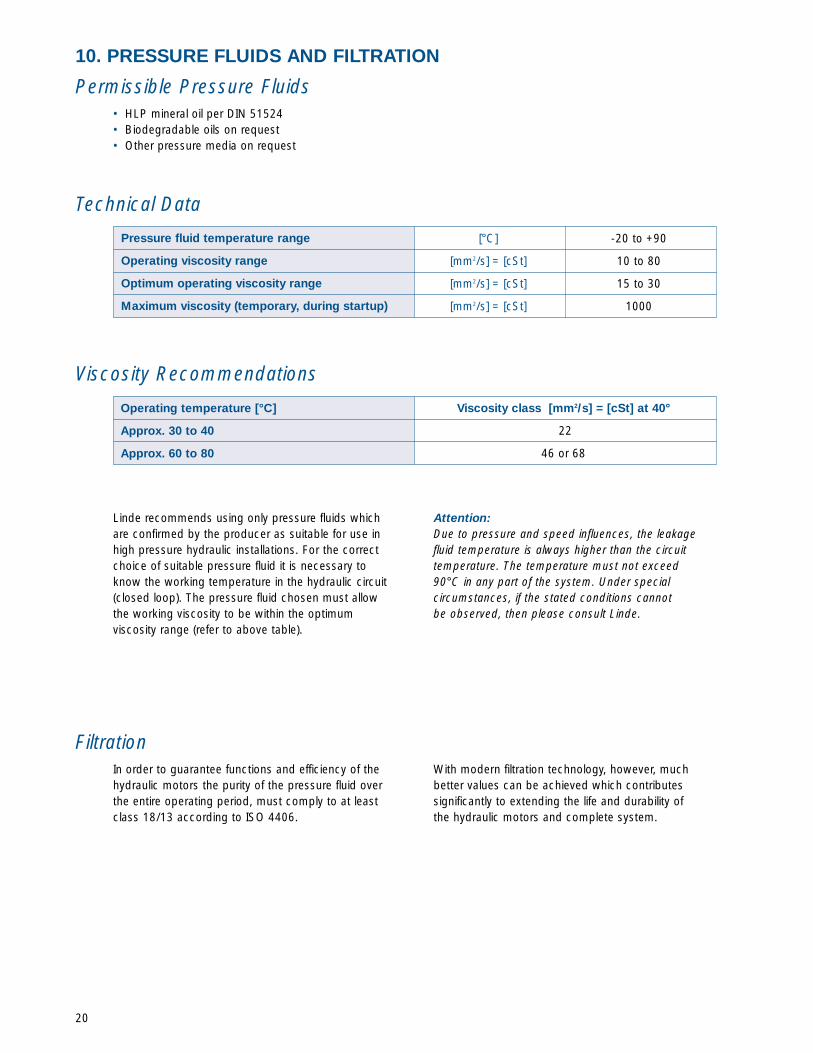
Permissible Pressure Fluids
10. PRESSURE FLUIDS AND FILTRATION
• HLP mineral oil per DIN 51524• Biodegradable oils on request• Other pressure media on request
Technical Data
Viscosity Recommendations
Linde recommends using only pressure fluids whichare confirmed by the producer as suitable for use inhigh pressure hydraulic installations. For the correctchoice of suitable pressure fluid it is necessary toknow the working temperature in the hydraulic circuit(closed loop). The pressure fluid chosen must allowthe working viscosity to be within the optimumviscosity range (refer to above table).
Attention:Due to pressure and speed influences, the leakagefluid temperature is always higher than the circuittemperature. The temperature must not exceed90°C in any part of the system. Under specialcircumstances, if the stated conditions cannotbe observed, then please consult Linde.
FiltrationIn order to guarantee functions and efficiency of thehydraulic motors the purity of the pressure fluid overthe entire operating period, must comply to at leastclass 18/13 according to ISO 4406.
With modern filtration technology, however, muchbetter values can be achieved which contributessignificantly to extending the life and durability ofthe hydraulic motors and complete system.
[°C]
[mm2/s] = [cSt]
[mm2/s] = [cSt]
[mm2/s] = [cSt]
-20 to +90
10 to 80
15 to 30
1000
Viscosity class [mm2/s] = [cSt] at 40°
22
46 or 68
Operating temperature [°C]
Approx. 30 to 40
Approx. 60 to 80
Pressure fluid temperature range
Operating viscosity range
Optimum operating viscosity range
Maximum viscosity (temporary, during startup)

11. AREAS OF APPLICATION
21

Linde Hydraulics CorporationP.O. Box 82 • 5089 Western Reserve Road • Canfield, Ohio 44406-0082
Telephone (330) 533-6801 • Fax (330) 533-6893Email [email protected] • Internet http://www.lindeamerica.com
LFH
-HM
F/V
/R-0
2 04
/00D
P/N 888 006 6483