hm-2470 manual rev2 - construction materials testing …€¦ · · 2017-01-135 most load,...
TRANSCRIPT

1
Instruction Manual Rev2.0
HM-2470A.3F ConMatic IPC

2
INTRODUCTION ........................................................................................................................................ 4
PRODUCT USE ........................................................................................................................................... 4
PRODUCT DESCRIPTION ........................................................................................................................ 4
GENERAL WARNINGS ............................................................................................................................. 6
SAFETY WARNINGS ..................................................................................................................................... 6 ELECTRICAL WARNINGS ............................................................................................................................. 6 SOFTWARE COPYRIGHT ............................................................................................................................... 6 IMPORTANT NOTICE .................................................................................................................................... 7 UPDATED PRODUCTS ................................................................................................................................... 7 FITNESS FOR APPLICATION .......................................................................................................................... 7
INSTALLATION AND SET-UP ................................................................................................................. 8
UNPACKING ................................................................................................................................................. 8 ELECTRICAL CONNECTIONS ........................................................................................................................ 8 AIR CONNECTIONS ...................................................................................................................................... 8 INSTRUMENT INPUT (DISPLACEMENT TRANSDUCER CONNECTIONS) ............................................................ 8
Single Device Connection ....................................................................................................................... 9 Multi Device Connection ........................................................................................................................ 9
OPERATION POWER SWITCH...................................................................................................................... 11 QUICK START GUIDE ................................................................................................................................. 11
Startup Scenarios .................................................................................................................................. 11
PANEL CONTROLS ................................................................................................................................. 12
KEY FUNCTIONS ........................................................................................................................................ 12 Set Up Key ............................................................................................................................................ 12 Loads Key ............................................................................................................................................. 12 Up Key .................................................................................................................................................. 12 Stop Key ................................................................................................................................................ 12 Down Key ............................................................................................................................................. 12
VERTICAL DISPLACEMENT TRANSDUCER .................................................................................................. 13 VERTICAL LOAD REGULATOR ................................................................................................................... 13 HIGH LOAD / LOW LOAD SELECTOR ......................................................................................................... 13 LOAD VALVE ............................................................................................................................................ 13 LOAD LIMIT .............................................................................................................................................. 13
Function Keys ....................................................................................................................................... 13 STATUS INDICATORS ................................................................................................................................. 14 FUSE .......................................................................................................................................................... 14
SAMPLE SETUP ......................................................................... ERROR! BOOKMARK NOT DEFINED.
SET-UP FUNCTIONS ............................................................................................................................... 14
DATE ......................................................................................................................................................... 14 TIME .......................................................................................................................................................... 15 UNITS ........................................................................................................................................................ 16 ENGINEERING SETUP .......................................................................................................................... 17 CONFIGURATION OF INPUT 1 DISPLACEMENT TRANSDUCER ......................................................................... 17
Sensor Min ............................................................................................................................................ 18 Sensor Max ........................................................................................................................................... 18

3
CONFIGURATION OF INPUT 2 LOAD TRANSDUCER ........................................................................................ 18 Sensor Min ............................................................................................................................................ 19 Sensor Max ........................................................................................................................................... 20
CONFIGURATION OF INPUT 3 LO LOAD TRANSDUCER .................................................................................. 20 Sensor Min ............................................................................................................................................ 21 Sensor Max ........................................................................................................................................... 21
CONFIGURATION OF INPUT 4 HI LOAD TRANSDUCER ................................................................................... 22 Sensor Min ............................................................................................................................................ 23 Sensor Max ........................................................................................................................................... 23
CALIBRATION ............................................................................................................................................ 24 CALIBRATION OF INPUT 1 DISPLACEMENT TRANSDUCER .............................................................................. 24 CALIBRATION OF INPUT 2 LOAD TRANSDUCER ............................................................................................. 26 CALIBRATION OF INPUTS 3&4 LO AND HIGH LOAD PRESSURE TRANSDUCER ................................................ 28 LOAD LIMITS CALIBRATION .......................................................................................................................... 29 DEVICE ID ................................................................................................................................................. 30 SENSOR LIMITS ..................................................................................................................................... 31 RAW_DATA ............................................................................................................................................ 31 SOFTWARE ................................................................................................................................................ 32
ELECTRICAL /ELECTRONICS SPECIFICATIONS .......................................................................... 33
HIDDEN FUNCTIONS .............................................................................................................................. 33
NOTES ........................................................................................................................................................ 35
HMTS “SOFTWARE” INSTRUCTIONS HM-1100SW ....................................................................... 49
©2005 Humboldt Mfg. Co.

4
Introduction This new consolidation device utilizes a pneumatic loading piston for applying the vertical load to the sample. The device is a self-contained tabletop model that eliminates the need for numerous weights used in dead weight systems. It has a built-in 4-channel Analogue to Digital converter with a digital display for setting the vertical load and the vertical displacement. The vertical displacements are measured with linear strain transducer. The vertical load measured with pressure transducer. Applying the vertical load is accomplished by setting the precision regulator to the required load. Load settings are verified on the readout accurate to .25%. Sample loads are obtained by the use of two pneumatic pistons. This new concept increases the accuracy and sensitivity of light load settings. A small diameter rolling diaphragm piston is capable of applying loads up to 100 lbs and a larger rolling diaphragm piston is capable of applying loads up to 2000 lbs. A stepping drive motor and controller maintains the desired load. The load is easily set with keypad and is maintained within 0.5% by microprocessor.
Product Use This product is intended for use only in accordance with the directions and specifications contained in this User Guide. Your HM-2470A has been configured according to ASTM specifications. The HM-2470A Digital ConMatic IPC has been designed for testing that complies with ASTM D2435, AASHTO T216, and applicable International standards.
Product Description The HM-2470A Digital ConMatic IPC have been designed to provide all the basic functions required to carry out one dimension consolidation test. The machine delivered with factory calibration. The HM-2470A Digital ConMatic IPC includes the following key features: • Control of a stepper motor driven load at 0.5% of applied load • Support for up to 4 analogue transducer inputs from 0 to 100 mV suitable for

5
most load, pressure, and displacement devices. Configuration and calibration capability is provided, and all-important data is stored in non-volatile memory for safe preservation. • Complete Data logger capacity for the one dimension consolidation Test. Test is fully configurable for automated Start, Stop and Logging conditions and can hold up to 1000 readings per test. • An LCD screen and 9 key membrane panel for easy presentation of results, parameter configuration, and machine control. To protect against operator misuse, key parameters can only be changed under pass code control. • Plug and play Serial port (RS232) communications with Humboldt Material Testing Software (HMTS) for controlling and downloading stored data. • Unique ID and RS485 communication port for multiple unit connections with a single computer. In addition, the machine offers a backlit LCD display, a touch-sensitive keypad, a battery-backed real time clock, and auto-conversion of calibration parameters between English and SI units.

6
General Warnings Safety Warnings Operators should take care to operate this machine under the maximum load restrictions. The machine is programmed at the factory to provide safety shutdown if the upper or lower maximum load is exceeded as well as if the upper instrument calibration is exceeded. Electrical Warnings Typically, there is no reason for the operator to open the machine. However, if the customer’s engineers attempt to change settings to the circuit board connected to the back panel, the machine must always be unplugged before this operation. Unplugging the internal connection to the back panel circuit board while the machine is under power will result in permanent damage to the circuit board. Manufacturer’s Rights and Responsibilities Software Copyright COPYRIGHT NOTICE
©2007 HUMBOLDT MFG. CO. All Rights Reserved.
This manual or parts thereof, may not be reproduced in any form without the expressed written
permission of HUMBOLDT MFG. CO.
UNPUBLISHED LICENSED PROPRIETARY WORK ©2006 HUMBOLDT MFG. CO.
The programmable, read-only memory, integrated circuit package contained in this equipment and covered with a copyright notice label contains proprietary and confidential software, which is the sole property of HUMBOLDT MFG. CO. It is licensed for use by the original purchaser of this equipment for a period of 99 years. Transfer of the license can be obtained by a request, in writing, from HUMBOLDT MFG. CO. With the exception of HUMBOLDT Authorized Service Facilities you may not copy, alter, de-compile, or reverse assemble the software in any fashion except as instructed in this manual. US copyright laws, trademark laws, and trade secrets protect the materials. Any person(s) and /or organizations that attempt or accomplish the above violation or

7
knowingly aid or abet the violation by supplying equipment or technology will be subject to civil damages and criminal prosecution. Important Notice The information contained herein is supplied without representation or warranty of any kind. Humboldt MFG. CO. therefore assumes no responsibility and shall have no liability, consequential or otherwise, of any kind arising from the use of the described equipment contained in this manual. Updated products The manufacturer reserves the right to change or modify product design or construction without prior notice and without incurring any obligation to make such changes and modifications on products previously or subsequently sold. Fitness for application The manufacturer makes no recommendations or claims regarding fitness for applications other than the specific tests as defined in this User Guide.

8
Installation and Set-up Unpacking Initial inspection should include checking for physical damage during shipping and obvious external damage to the product. Package contents are defined by your packing list. Each ConMatic IPC is configured according to customer specifications. In your inspection, make certain that the contents of your shipment match the documentation provided by your packing list. Place unit on a flat smooth surface and use leveling feet (supplied) and a bubble level to ensure that the unit is level side-to-side and back-to-front. Electrical Connections The HM-2470A is equipped with an internal, digital, switching power supply, which allows it to be used with most power configurations throughout the world. The unit is supplied with an IEC electrical cord with a standard 110V plug. The HM-2470A arrives ready for operation. Attach the supplied IEC electrical cord to the machine and plug into a standard wall receptacle for use in the United States. For locations other than the U.S., replace the supplied electrical cord with an IEC cord with the correct plug for your application. The supplied cord can also be used by cutting the standard plug from the cord and attaching the correct plug.
1 Air Connections The HM-4170 requires a clean compressed air supply of maximum 120psi (800 kpa). The air should be free of oil and moisture an in line filter is highly recommended. Instrument Input (displacement transducer connections) The HM-2470A has an instrumentation input located on the back panel to accommodate displacement transducer connections. If you are using third-party cables for transducers connections, make sure they are wired to be compatible with the HM-2470A. Consult Figure #1 for a compatible reference wiring diagram. Plugs to connect third-party instrumentation to the Humboldt HM-2470A are available, order part HM-000474.

9
Figure1. Compatibility wiring diagram for 3rd party cables Computer connection
Single Device Connection The HM-2470A can be connected to a PC computer to take advantage of Humboldt’s HMTS software capabilities, conduct real time data logging and enhanced report generation. This is accomplished via the RS-232 port on the back panel of the machine (refer to Figures 2 & 4.). Use a RS-232 cable (supplied) and attach it between the computer’s RS-232 port and the HM-2470A. The minimum compatible computer configuration is a PC with Pentium 4 1.8 GHz processor, 512 MB of RAM and a 40GB hard drive. Windows 2000 or XP with SP2 or later.
Multi Device Connection Multi devices, such as HM-3000s, HM-2325A, HM-2330D MiniLoggers, HM-2700A, HM-2700D Direct shear Apparatus can be connected to a computer via the HM-2470A’s RS-485 port. This allows you to daisy-chain several devices to the same computer; require HM-000375 (RS232 to RS485 converter not included). Use a standard CAT 5 cable (not included) to link the additional device’s output port to the HM-2470A’s RS-485 input port (refer to Figures 2 & 4). Dip switches need to be set to primary or secondary usage (see Figure 5). The minimum compatible computer configuration is a PC with Pentium 4, 1.8 GHz processor, 512 MB of RAM, and a 40GB hard drive Windows 2000 or XP with SP2 or later.

10
Figure 4. Diagram illustrating computer and multiple device connections.
Figure 2. Rear panel of HM-2470A showing Analogue Port, RS-232 Port, RS-485 Input and Output and the four instrumentation channel inputs.

11
Figure 5. Back Panel electronic board showing location of Dip switches for setting Computer connections. For single device setups, set Dip Switch #4 to on (default setting). For multiple device setups, set Dip Switch #4 to off. Operation Power Switch The Power Switch is located in the back panel on the rear of the machine above the electrical cord inlet. Also, located between the electrical cord inlet and the Power Switch is the Fuse Compartment. The HM-2470A uses a 10 amp fuse. To begin operation, press the Power Switch.
Fuse Compartment. Figure 6. HM-2470A Power Switch, Electrical Cord Inlet and Fuse Compartment. Quick Start Guide
Startup Scenarios If your HM-2470A All instrumentation shipped with your unit is calibrated and assigned specific channels for use. These channels are marked on the corresponding instrumentation. Unless it is required by your QC/QA program, there is no need to configure or calibrate the machine. It is ready for use.

12
Panel Controls Key Functions
Figure 7 HM-2470A Front Control
Set Up Key Pushing the Set Up Key brings up the main set up screen from which you can run a test, review your last test, access the engineering set up menus and set the date, time, units, standards criteria. This key also is used to return to a previous screen.
Loads Key Pushing the loads key allow the user to set a target load
Up Key Pushing the Up Key allows you to apply the load to specimen.
Stop Key Pushing the Stop Key stops platen movement. When the key is pushed the red light next to it is lit.
Down Key Pushing the Down Key allows you to remove the load from specimen.

13
Vertical Displacement Transducer The LSCT is connected to the rear of the cabinet with a five-pin din plug to measure the deformation of the specimen. Vertical Load Regulator A precision motorized regulator is used to set and maintain the air pressure to the pistons, which provides load to the sample. The regulator is sensitive to 1/8 in variations in water column. Select the load required from the load setting table. NOTE: THE CONSOLIDATION LOAD PAD, POROUS STONE, and STAINLESS STEEL BALL HAVE NOT BEEN INCLUDED IN THE LOAD SETTING CALIBRATIONS. High Load / Low Load Selector The HM-4170 has two air pistons. The LOW LOAD piston is used for loads up to 100 lbs (5kgf). The HIGH LOAD piston is used for loads up to 2000 lbs (1000kgf). Load Valve This electronic valve is actuated by two solenoids. When open, it allows air to flow from the regulator to the pistons (HIGH or LOW LOAD) selected. Load Limit These electronic soft switches provide a low and a high limits. Adjustment of these switches is made by the selecting engineering setup and load limits option selected. The home position is zero loads.
Function Keys The four function keys are used to navigate through the HM-2470A’s menu-driven display. The function keys correspond with the command lines on the HM-2470A’s menu display. F1 corresponds with the first command line; F2, the second, etc. Command lines that are active in any display will be proceeded by an (*). If no (*) is present, the corresponding function key is not active.

14
Status Indicators Used to indicate which piston is on for low and high loads for low loads one light will be ON and for the high loads two lights will be ON. Fuse 6 Amp SLOW BLOW fuse located in the cabinet rear.
Set-up Functions Date To set the Date press until you see this screen: Press you will see this screen: Press you will see this screen: Press (DATE/UNIT/STANDARD). You should see this screen: Press (CHANGE DATE). You should see this screen:
HUMBOLDT HM-2470A DISP 0.0000 LO LOAD 0.0 * RUN
* ENGINEERING SETUP * SENSOR LIMITS OFF * RAW_DATA * MORE SETUP
* RECALL CALIBRATION * CHANGE DEVICE ID * DATE/UNIT/STANDARD * MANUFACTURES INFO
* CHANGE DATE * CHANGE TIME * UNIT= ENGLISH/METRIC

15
Press (DATE) to select the month/date/year. Press
(INCREASE) or Press (DECREASE) to change the appropriate number. To return to any prior screen you can always press Time To set the Time press until you see this screen: Press you will see this screen: Press you will see this screen: Press (DATE/UNIT/STANDARD). You should see this screen: Press (CHANGE TIME). You should see this screen:
* DATE = "MM/DD/YY" * INCREASE * DECREASE
* TIME = "HH/MM/SS" * INCREASE * DECREASE
* CHANGE DATE * CHANGE TIME * UNIT= ENGLISH/METRIC
* RECALL CALIBRATION * CHANGE DEVICE ID * DATE/UNIT/STANDARD * MANUFACTURES INFO
* ENGINEERING SETUP * SENSOR LIMITS OFF * RAW_DATA * MORE SETUP
HUMBOLDT HM-2470A DISP 0.0000 LO LOAD 0.0 * RUN

16
Press (TIME) to select the HOURS/MINUTES/SECONDS. Press (INCREASE). or Press (DECREASE) to change the appropriate number. To return to any prior screen you can always press Units To set the Units the HM-2470A will use to display results, press until you see this screen: Press you will see this screen: Press you will see this screen: Press (DATE/UNIT/STANDARD). You should see this screen: Press (units) to toggle between English and Metric Units.
HUMBOLDT HM-2470A DISP 0.0000 LO LOAD 0.0 * RUN
* ENGINEERING SETUP * SENSOR LIMITS OFF * RAW_DATA * MORE SETUP
* RECALL CALIBRATION * CHANGE DEVICE ID * DATE/UNIT/STANDARD * MANUFACTURES INFO
* CHANGE DATE * CHANGE TIME * UNIT= ENGLISH/METRIC

17
Select the standard desired—the flashing standard is the active choice. To return to any prior screen you can always press ENGINEERING SETUP Configuration of input 1 Displacement Transducer If you are adding new instrumentation, changing existing instrumentation or reconfiguring the HM-2470A’s channel setup, you need to configure the input for use with the device you have. To configure instrumentation input, Press you will see this screen: Press (ENGINEERING SETUP) you should see this screen: Press (CONFIGURATION) you should see this screen You will be asked for a password, enter:
You should see this screen:
HUMBOLDT HM-2470A DISP 0.0000 LOAD 0.0 * RUN
* ENGINEERING SETUP * SENSOR LIMITS OFF * RAW_DATA * MORE SETUP
* CONFIGURATION * CALIBRATION * MORE ENGINEERING
CONFIGURATION MENU * SELECT INPUT 1 * CONFIGURE DISP
ENTER PASSWORD ---- + ---- + ---- + -----+ ----

18
Press (SELECT INPUT 1) to scroll through and choose the input you wish to configure. Once you have selected an input press (CONFIGURE DISP) you should see this screen:
Sensor Min The Sensor Zero (SENSOR MIN) is not configurable and is set at 0.
Sensor Max Press (SENSOR MAX) to set the Sensor Maximum value. You should see this screen: Press (SENSOR MAX) to move between the numbers. Keep pressing until the digit you want to change is flashing. Once you have selected the number you want to change, press (INCREASE) or (DECREASE) to change the number to the desired value. Below is a configuration chart for Humboldt instrumentation. These are the numbers that correspond to each Humboldt sensors. Displacement Transducer Part# English Max (in.) Metric Max (mm) 0.4" (10.0mm) HM-2310.04 0.40000 10.000 1.0" (25.4mm) HM-2310.10 01.0000 25.000 To return to any prior screen you can always press Configuration of input 2 Load Transducer If you are adding new instrumentation, changing existing instrumentation or reconfiguring the HM-2470A’s channel setup, you need to configure the channel for use with the devices you have. To configure instrumentation input,
INPUT 1 CONFIGURE NAME = DISP SENSOR MIN= 0 * SENSOR MAX= 01.0000
“CH1” MAX SETUP * SENSOR MAX = 01.0000 * INCREASE * DECREASE
HUMBOLDT HM-2470A DISP 0.0000 LO LOAD 0.0 * RUN

19
Press you will see this screen: Press (ENGINEERING SETUP) you should see this screen: Press (CONFIGURATION) you should see this screen You will be asked for a password, enter:
You should see this screen: Press (SELECT INPUT 2) to scroll through and choose the input you wish to configure. Once you have selected an input press (CONFIGURE LOAD) you should see this screen:
Sensor Min The Sensor Zero (SENSOR MIN) is not configurable and is set at 0.
* ENGINEERING SETUP * SENSOR LIMITS OFF * RAW_DATA * MORE SETUP
* CONFIGURATION * CALIBRATION * MORE ENGINEERING
CONFIGURATION MENU * SELECT INPUT 2 * CONFIGURE LOAD
INPUT 2 CONFIGURE NAME = LOAD SENSOR MIN= 0 * SENSOR MAX= 2000.0
ENTER PASSWORD ---- + ---- + ---- + -----+ ----

20
Sensor Max Press (SENSOR MAX) to set the Sensor Maximum value. You should see this screen: Press (SENSOR MAX) to move between the numbers. Keep pressing until the digit you want to change is flashing. Once you have selected the number you want to change, press (INCREASE) or (DECREASE) to change the number to the desired value. Below is a configuration chart for Humboldt instrumentation. These are the numbers that correspond to each Humboldt sensors. Load Cell English Max (lbf) Metric Max (kN) 2000 lb. (10kN) 2000.0 10.000 To return to any prior screen you can always press Configuration of input 3 Lo Load Transducer If you are adding new instrumentation, changing existing instrumentation or reconfiguring the HM-2470A’s channel setup, you need to configure the input for use with the devices you have. To configure instrumentation input, Press you will see this screen: Press (ENGINEERING SETUP) you should see this screen:
“CH2” MAX SETUP * SENSOR MAX = 00100.0 * INCREASE * DECREASE
HUMBOLDT HM-2470A DISP 0.0000 LOAD 0.0 * RUN
* ENGINEERING SETUP * SENSOR LIMITS OFF * RAW_DATA * MORE SETUP
* CONFIGURATION * CALIBRATION * MORE ENGINEERING

21
Press (CONFIGURATION) you should see this screen You will be asked for a password, enter:
You should see this screen: Press (SELECT INPUT 3) to scroll through and choose the input you wish to configure. Once you have selected an input press (CONFIGURE LO LOAD) you should see this screen:
Sensor Min The Sensor Zero (SENSOR MIN) is not configurable and is set at 0.
Sensor Max Press (SENSOR MAX) to set the Sensor Maximum value. You should see this screen: Press (SENSOR MAX) to move between the numbers. Keep pressing until the digit you want to change is flashing. Once you have selected the number you want to change, press (INCREASE) or (DECREASE) to change the number to the
CONFIGURATION MENU * SELECT INPUT 3 * CONFIGURE LO LOAD
INPUT 3 CONFIGURE NAME = LO LOAD SENSOR MIN= 0 * SENSOR MAX= 100.0
ENTER PASSWORD ---- + ---- + ---- + -----+ ----
“CH3” MAX SETUP * SENSOR MAX = 100.0 * INCREASE * DECREASE

22
desired value. Below is a configuration chart for Humboldt instrumentation. These are the numbers that correspond to each Humboldt sensors. Lo Load English Max Metric Max 100.0 100.0 0.500 To return to any prior screen you can always press Configuration of input 4 Hi Load Transducer If you are adding new instrumentation, changing existing instrumentation or reconfiguring the HM-2470A’s channel setup, you need to configure the input for use with the devices you have. To configure instrumentation input, Press you will see this screen: Press (ENGINEERING SETUP) you should see this screen: Press (CONFIGURATION) you should see this screen You will be asked for a password, enter:
You should see this screen:
HUMBOLDT HM-2470A DISP 0.0000 LOAD 0.0 * RUN
* ENGINEERING SETUP * SENSOR LIMITS OFF * RAW_DATA * MORE SETUP
* CONFIGURATION * CALIBRATION * MORE ENGINEERING
ENTER PASSWORD ---- + ---- + ---- + -----+ ----

23
Press (SELECT INPUT 3) to scroll through and choose the input you wish to configure. Once you have selected an input press (CONFIGURE LO LOAD) you should see this screen:
Sensor Min The Sensor Zero (SENSOR MIN) is not configurable and is set at 0.
Sensor Max Press (SENSOR MAX) to set the Sensor Maximum value. You should see this screen: Press (SENSOR MAX) to move between the numbers. Keep pressing until the digit you want to change is flashing. Once you have selected the number you want to change, press (INCREASE) or (DECREASE) to change the number to the desired value. Below is a configuration chart for Humboldt instrumentation. These are the numbers that correspond to each Humboldt sensors. Lo Load English Max Metric Max 2000.0 2000.0 10.000 To return to any prior screen you can always press
CONFIGURATION MENU * SELECT INPUT 4 * CONFIGURE HI LOAD
INPUT 4 CONFIGURE NAME = HI LOAD SENSOR MIN= 0 * SENSOR MAX= 2000.0
“CH4” MAX SETUP * SENSOR MAX = 2000.0 * INCREASE * DECREASE

24
Calibration Calibration of input 1 Displacement Transducer This menu item is used to calibrate the HM-2470A. WARNING: Calibration should only be performed by trained personnel with proper, certified equipment. The HM-2470A and its instrumentation should be calibrated once a year or as the need arises. To calibrate a channel, press Press (ENGINEERING SETUP). You should see this screen: Press
(CALIBRATION) You will be asked for a password, enter:
You should see this screen: Press (SELECT INPUT 1) to scroll through and choose the sensor you wish to calibrate. Once you have chosen the desired channel you wish to calibrate press (CLEAR CALIBRATION). WARNING: IF YOU CLEAR A CALIBRATION IT IS LOST FOREVER! After the calibration has
HUMBOLDT HM-2470A DISP 0.0000 LOAD 0.0 * RUN
* ENGINEERING SETUP * SENSOR LIMITS OFF * RAW_DATA * MORE SETUP
* CONFIGURATION * CALIBRATION * MORE ENGINEERING
CALIBRATION MENU * SELECT INPUT 1 * CALIBRATE DISP * CLEAR CALIBRATION
ENTER PASSWORD ---- + ---- + ---- + -----+ ----

25
been cleared, Press
(CALIBRATE CHANNEL) You should see this screen: Press to SET GAIN. With the instrument you wish to calibrate mounted to a calibration frame attached to the HM-2470A, record the sensor min value with no load on the instrument (X divisions). Next, apply the full engineering load value to instrument on the calibration frame and again, record the sensor min reading (X divisions). Subtract the two values. This value should be a number larger than the sensor maximum rating. If not, you need to increase the gain to compensate for the difference. Press
(SET GAIN) and repeat until the difference between the two values is more than the maximum sensor rating. EXAMPLE: If you are calibrating a 100.0 lb. load cell, to a single decimal point you need a difference value of at least 1,000 divisions. If you register a value reading of 450 divisions with no load on the sensor and a 8450 divisions at full load on the instrument, your difference value will be 8000 divisions. (1370 – 450 = 920). To increase the gain press
(SET GAIN) until you have more than 1,000 divisions. Once the gain has been set, the zero point needs to be set. To set the zero point, apply the zero displacement to the sensor and press (SET SENSOR MIN). Now apply the one inch displacement to the sensor and press (SET SENSOR MAX).
To return to any prior screen you can always press
DISP CALIBRATION * SET GAIN 4 * SET SENSOR MIN 1195 * SET SENSOR MAX 0
DISP CALIBRATION * SET GAIN 4 * SET SENSOR MIN 1195 * SET SENSOR MAX 0
DISP CALIBRATION * SET GAIN 4 * SET SENSOR MIN 1195 * SET SENSOR MAX 15124

26
Calibration of input 2 Load Transducer This menu item is used to calibrate the HM-2470A. WARNING: Calibration should only be performed by trained personnel with proper, certified equipment. The HM-2470A and its instrumentation should be calibrated once a year or as the need arises. To calibrate a channel, press Press (ENGINEERING SETUP). You should see this screen: Press
(CALIBRATION) You will be asked for a password, enter:
You should see this screen: Press (SELECT INPUT 2) to scroll through and choose the sensor you wish to calibrate. Once you have chosen the desired channel you wish to calibrate press (CLEAR CALIBRATION). WARNING: IF YOU CLEAR A CALIBRATION IT IS LOST FOREVER! After the calibration has been cleared, Press
HUMBOLDT HM-2470A DISP 0.0000 LO LOAD 0.0 * RUN
* ENGINEERING SETUP * SENSOR LIMITS OFF * RAW_DATA * MORE SETUP
* CONFIGURATION * CALIBRATION * MORE ENGINEERING
CALIBRATION MENU * SELECT INPUT 2 * CALIBRATE DISP * CLEAR CALIBRATION
ENTER PASSWORD ---- + ---- + ---- + -----+ ----

27
(CALIBRATE CHANNEL) You should see this screen: Press to SET GAIN. With the instrument you wish to calibrate mounted to a calibration frame attached to the HM-2470A, record the sensor min value with no load on the instrument (X divisions). Next, apply the full engineering load value to instrument on the calibration frame and again, record the sensor min reading (X divisions). Subtract the two values. This value should be a number larger than the sensor maximum rating. If not, you need to increase the gain to compensate for the difference. Press
(SET GAIN) and repeat until the difference between the two values is more than the maximum sensor rating. EXAMPLE: If you are calibrating a 100.0 lb. load cell, to a single decimal point you need a difference value of at least 1,000 divisions. If you register a value reading of 450 divisions with no load on the sensor and a 8450 divisions at full load on the instrument, your difference value will be 8000 divisions. (1370 – 450 = 920). To increase the gain press
(SET GAIN) until you have more than 1,000 divisions. Once the gain has been set, the zero point needs to be set. To set the min point, apply a load 0f ZERO pounds to the sensor and press (SET SENSOR MIN). Now apply
the 2000 lb load to the sensor by pressing until 2000 lb achieved on the calibration equipment then and press (SET SENSOR MAX).
To return to any prior screen you can always press
HI LOAD CALIBRATION * SET GAIN 16 * SET SENSOR MIN 5431 * SET SENSOR MAX 0
HI LOAD CALIBRATION * SET GAIN 16 * SET SENSOR MIN 5431 * SET SENSOR MAX 0
HI LOAD CALIBRATION * SET GAIN 16 * SET SENSOR MIN 5431 * SET SENSOR MAX 29907

28
Calibration of inputs 3&4 Lo and High Load Pressure Transducer This menu item is used to calibrate the HM-2470A. WARNING: Calibration should only be performed by trained personnel with proper, certified equipment. The HM-2470A and its instrumentation should be calibrated once a year or as the need arises. To calibrate a channel, press Press (ENGINEERING SETUP). You should see this screen: Press
(MORE CALIBRATION) You should see this screen: Press
(CALIBRATE PRESSURES) You should see this screen:
HUMBOLDT HM-2470A DISP 0.0000 LO LOAD 0.0 * RUN
* ENGINEERING SETUP * SENSOR LIMITS OFF * RAW_DATA * MORE SETUP
* CONFIGURATION * CALIBRATION * MORE ENGINEERING
* LOAD LIMITS * CLEAR LOAD LIMITS * CALIBRATE PRESSURES
* AUTO CALIBRATE LOAD 4911.0 LO LOAD CALIBRATED HI LOAD CALIBRATED

29
With the load cell which has been calibrated with input 2 mounted between the cross bar and the top surface of the machine with as little as possible day light between the load cell and the top surface. Press to CALIBRATE low and high load pressure transducers. The machine will automatically calibrate the low and the high load pressures. To return to any prior screen you can always press Load limits calibration To set the upper and lower limits of the loads until the following setup screen appears: Press you will see this screen: Press (ENGINEERING SETUP). You should see this screen: Press (MORE ENGINEERING). You should see this screen:
HUMBOLDT HM-2470A DISP 0.0000 LOAD 0.0 * RUN
* ENGINEERING SETUP * SENSOR LIMITS OFF * RAW_DATA * MORE SETUP
* CONFIGURATION * CALIBRATION * MORE ENGINEERING
* AUTO CALIBRATION LOAD 0.0 LBS POSITION 0000

30
Press (AUTO CALIBRATION) the auto calibration of lower and upper loads limits will be performed automatically. Important not make sure that the HM-4170A is connected to compressed air supply and there are sufficient pressure available OF 120psi (800kpa). Device ID Factory set device ID to 1, if multiple units are connect to a single computer a unique device ID for each unit has to be establish for the computer to recognize the correct instrumentation and the correct motors. To set the Device ID the HM-2470A will use, press until you see this screen: Press you will see this screen: Press you will see this screen: Press (CHANGE DEVICE ID). You should see this screen: Press to increase the ID number or press to decrease the number. Once the ID has been changed, press to go back to previous menu. Note: Up to 16 devices
* REVIEW LAST TEST * RUN TEST * MORE SETUP
* ENGINEERING SETUP * SENSOR LIMITS OFF * RAW_DATA * MORE SETUP
* RECALL CALIBRATION * CHANGE DEVICE ID * DATE/UNIT/STANDARD * MANUFACTURES INFO
DEVICE ID = 01 * INCREASE * DECREASE

31
can be connected to a single computer. SENSOR LIMITS Sensor upper limits can be set to ON or OFF. If the Sensor’s Upper limit is set to ON and the motor/test is in progress, when the sensor reaches its upper limit, the motor/test will stop and a warning message will be displayed. In addition, if a sensor has been unplugged from the instrumentation back panel, the same warning message will be displayed. RAW_DATA RAW-DATA refers to the digital output of the sensors prior to apply the calibration factor and conversion into engineering units.

32
Software The HM-2470A comes with Humboldt’s HMTS data collection software. This software can be used to collect data from tests by creating user-defined test parameters (start/stop). The resulting data can then be opened in Microsoft Excel to view the data collected, as well as create a simple table and graph. Optional pre-defined reporting software module and template is available for specific tests, such as One dimension consolidation test. This module provides more control over start and stops conditions for specific test, as well as provides extended reporting capabilities. Contact Humboldt for more information.
Table/graph and Excel output of user-defined test generated from software included.

33
Electrical /Electronics Specifications Voltage 110/220 VAC 50/60HZ Current 8.5 Amps Analogue to digital converter 16 Bit Data storage 4000 Reading Data collection rate 100 ms Computer port RS232 or RS485 Phone support is available for general operating questions and trouble shooting problems between 8am and 5pm Eastern Time. Please call:
1.800.537.4183 1.919.832.6509 or fax: 1.919.833.5283
[email protected] For sales and sales-related information, such as available accessories, general sales questions, pricing, please call:
1.800.544.7220 1.708.456.6300 or fax: 1.708.456.0137
Hidden Functions The following are functions that are possible if needed, to access them, please contact support at the numbers or email address listed above. 1. System reset Reset available in the case of a serious problem in system memory. This will cancel all data in memory calibration/configuration of all channels. To activate the system reset turn the system off press F4 and hold, turn the system on then release F4. 2. Replacing Factory calibration The Factory configuration and calibration of the system stored in EEPROM for recalling in case of system reset required. To replace the factory calibration with a new calibration turn the system off press F1 and hold, turn the system on, release F1 then press F1 again. 3. Low / High Load From the main menu you could switch manually from low load to high load by pressing F1 the status light will indicate the following both LED are off when the low load activated the upper LED is on when the high load activated.

34
4. Load Release From the main menu you could release the load manually from low load or high load by pressing F2 the motor will release load and return to home position. 5. Tare Function From the main menu you could tare the load to zero manually by pressing F3.

35
NOTES

36
Workshop on ASTM-D2435 / AASHTO-T216 ONE –DIMENSIONAL CONSOLIDATION
PROPERTIES OF SOILS
Testing objectives:
In this test method a soil specimen is restrained laterally and loaded axially with total stress increments. Each stress increment is maintained until excess pore water pressures are completely dissipated. During the consolidation process, measurements are made of change in the specimen height and these data are used to determine the relationship between the effective stress and void ratio or strain, and the rate at which consolidation can occur by evaluating the coefficient of consolidation.
Consolidation Equipment
ASTM INSTRUCTIONS The requirements for equipment needed to perform satisfactory tests are given in the following sections.
1 Load Device— HM-1100 / HM-2432 / HM-2470A a. A suitable device for applying vertical loads or total stresses to the
specimen. b. The device shall be capable of maintaining specified loads for long periods
of time with a precision ±0.5% of the applied load. c. The device shall permit quick application of a given load increment without
significant impact. d. The frames that hold the specimen shall be sufficiently rigid to prevent their
distortion during loading.
2 Consolidometer — HM-1220.25 / HM-1210.25 /HM-1230.25
a. A device to hold the specimen in a ring that is either fixed to the base or floating (supported by friction on periphery of specimen).

37
b. Porous disks on each face of the specimen Permitting drainage of water through the porous inserts at the top and bottom boundaries of the specimen.
c. The inside diameter of the ring shall be determined to a tolerance of 0.075 mm (0.003 in.).
d. Has means of submerging the specimen in water. e. Has means of measuring change in height of specimen. f. Has a means of transmitting the concentric vertical load to the porous disks.
3 The Specimen (Cutter)Ring— HM-1220.XX.8
a. The minimum diameter shall be 2.0 in (50mm) b. The minimum height shall be 0.5 in (12mm), but shall be not less than ten
times the maximum particle diameter. c. The minimum diameter to height ratio shall be 2.5 a greater ratio is
recommended. d. Rigid such that ring diameter does not change under greatest applied load. e. Made of noncorrosive material. f. Inner surface highly polished or coated with low-friction material.
4 Porous Inserts— HM-1220.XX.11 (Upper) and HM-1220.25.7 (Lower) a. It’s Function to allow drainage from the soil specimen along the top and
bottom boundaries. b. The permeability of the insert should be substantially greater than that of
the soil, but should be textured fine enough to prevent excessive intrusion of the soil into the pores of the insert.
c. The diameter or width of the top porous insert or plate shall be 0.01 to 0.02 in. (0.2 to 0.5mm) less than that of the inside of the ring.
d. Thickness of disks shall be sufficient to prevent breaking. e. The disks shall be clean and free from cracks, chips, and nonuniformities.
5 Metal Calibration Disk— HM-HM-4189.XX a. Made of copper or hard steel b. Same height as test specimen. c. Diameter up to 5 mm smaller than specimen diameter.
6 Controlled High Humidity Room—if required
a. Soil moisture change minimized (Moisture loss during sample preparation does not exceed 0.5%) .
7 Balance—HB-4533 a. A balance or scale conform to the requirements of Specification D 4753
readable (with no estimate) to 0.1 % of the test mass or better. b. Sensitive to 0.1 g.
8 Deformation Indicators —

38
Either dial gauge or displacement transducers capable of a. Measuring the change in height of the specimen, with a sensitivity of at
least 0.0001 in. (0.0025 mm). H-4471 / HM-2310.04 / HM-4469.10
9 Timer—H-2260 or H-3575A A timing device indicating the elapsed testing time to the nearest 1 s shall be used to obtain consolidation data.
10 Testing Environment
The consolidation test shall be performed in an environment where temperature fluctuations are less than ±4°C (±7.2°F) and there is no direct contact with sunlight.
11 Wire Saw—HM-3175
12 Steel Straightedge—H-4144
13 Water Content cans—H-4929
14 Oven —H-30145E
Maintains 110±5°C (230±9°F)
15 Air Compressor if using HM-2432 or HM-2470A.3F 80 gallon tank, 10CFM@90 PSI, Working Pressure 170PSI, Maximum Pressure 225PSI, 2 cylinder, 2 stage pump
16 Computer, Printer and Internet Connections

39
Calibration
a. Measuring Instrumentation, this calibration is to determine vertical displacement is accurately calibrated.
b. Apparatus deflection, the calibration is to determine the deformation of the apparatus when subject to the consolidation load.
1. Assemble the consolidometer device with metal calibration disk 2. Position the vertical (Normal) displacement indicator. 3. Record the zero or no load reading. 4. Apply increments of normal force and record the vertical
displacement indicator. 5. Remove the applied normal force in reverse sequence and record
the vertical displacement indicator. 6. At each load applied tabulate the corrections to be applied to the
measured deformation of test specimen.
c. Normal force, the calibration is to determine the normal force required to achieve the desired normal stress
1. Dead weight machines (weights are available in kg or TSF (for 2.5 inch sample). The load applied via 10:1 ratio lever arm hanger. For example to apply 1 TSF (2ksf) on a 2.5inch diameter sample with 10:1 lever a 6.817lb (3.092kg) dead weight required.
2. Pneumatic machines (supplied pressure display is available in
psi or kpa). For example to apply 1 TSF (2 KSF) on a 2.5inch diameter sample a 6.817lb (3.092kg) weight requires therefore a supply pressure of approximately 68 psi (with a low load) or a supply pressure of approximately 3.7 psi (with a high load) Please refer to the normal load calibration chart supplied with your machine.

40
Initial Stage Test Specimen Preparation
1 Undisturbed Specimens a. Specimens handled to min. disturbance, changes in cross-section,
compression, or change in water content.
b. Trimmed specimens prepared in controlled environment where water content change is minimized
c. Voids from pebbles or crumbling filled with remolded soil from trimmings
d. Final trimming made flush with end surfaces done with steel straightedge.
e. One or more water content determinations of trimmings determined
according to ASTM D2216
f. Determine the initial wet mass of the specimen, MTo in the consolidation ring by measuring the mass of the ring with specimen and subtracting the tare mass of the ring.
g. Determine the initial height, Ho, of the specimen to the nearest 0.025 mm
(0.001 in.) by taking the average of at least four evenly spaced measurements over the top and bottom surfaces of the specimen using a dial comparator or other suitable measuring device.
h. Compute the initial volume, Vo, of the specimen to the nearest 0.25 cm3 (0.015 in.3) from the diameter of the ring and the initial specimen height.
2 Testing procedure
a. Assemble the ring with specimen, porous disks, filter disks, and consolidometer. Note: Porous disks may be damp or dry, depending on soil type. Dry porous disks and filters must be used with dry, highly expansive soils
b. Enclose consolidometer in loose-fitting plastic or rubber membrane to prevent evaporation, unless specimen is inundated after applying seating load.
c. Place consolidometer in loading device and apply seating pressure of 5 kPa (100 lbf/ft2) (or about 2 - 3 kPa (50 lbf/ft2) or less for very soft soils). Note: Additional load may be added to prevent specimen from swelling, if necessary
d. Adjusted deformation indicator and initial zero reading recorded
immediately after application of seating load

41
Consolidation Stage
e. If testing a specimen that was saturated under field conditions or obtained
below water table: i. (1). Inundate Specimen shortly after application of seating load.
ii. (2). Increased load as required to prevent swelling during inundation.
iii. (3). Record load required to prevent swelling and resulting deformation reading.
iv. Note: If specimen inundation is delayed to simulate specific conditions, inundation must occur at sufficiently large pressure to prevent swell. In this case, time deformation readings should be taken during inundation.
f. The specimen is to be subjected to increments of constant total stress with specific loading schedule dependent on purpose of test. Note: Standard loading schedule is 12, 25, 50, 100, 200, etc. kPa (250, 500, 1000, 2000, 4000, etc. lbf/ft2).
g. Recorded height or change in height of specimen before applying each pressure increment and at set time intervals for each load increment.
h. Readings taken at approximately 0.1, 0.25, 0.5, 1, 2, 4, 8, 15 and 30
minutes, 1, 2, 4, 8 and 24 etc. hours, measured from time of each incremental pressure application.
i. When rebound or unloading characteristics are required, soil unloaded in
reverse order and readings taken as before.
j. At completion of test, wipe free water from specimen and ring, and specimen weighed in ring
k. Determine water content determined according to ASTM D2216 (T265).

42
Calculation
1. Calculations as shown are based on the use of SI units. Other units are permissible, provided the appropriate conversion factors are used to maintain consistency of units throughout the calculations.
2. Specimen Properties:
Obtain the dry mass of the total specimen, Md, by direct measurement or for the case where part of the specimen is used for index testing, calculate the dry mass as follows:
Where: MTf = moist mass of total specimen after test, g or Mg, and wfp= water content (decimal form) wedge of specimen taken after test.
3. Calculate the initial and final water content, in percent, as follows:
Where: Md = dry mass of specimen, g or Mg, and MTo = moist mass of specimen before test, g or Mg.
4. Calculate the initial dry density of the specimen as follows:
Where: rd = dry density of specimen, g/cm3
or Mg/m3, and Vo = initial volume of specimen, cm3
or m3.
5. Calculate the dry unit weight of the specimen as follows:

43
6. Compute the volume of solids as follows:
Where: G = specific gravity of the solids, and rw = density of water, 1.0 g/cm3
or Mg/m3
7. Since the cross-sectional area of the specimen is constant throughout the test, it is convenient for subsequent calculations to introduce the term “equivalent height of solids,” defined as follows:
Where: A = specimen area, cm2 or m2.
8. Calculate void ratio before and after test as follows:
Where: Ho = initial specimen height, cm or m, and Hf = final specimen height, cm or m.
9. Calculate the degree of saturation, in percent, before and after test as follows:

44
10. Time-Deformation Properties Log of time method
a. Plot the deformation readings, d, versus the log of time (normally in
minutes) for each increment of load. Draw tangent C Draw tangent D The intersect point E = d100 Select point F (0.5 min) Select point G (0.5 x 4 min) Measure the vertical distance H = G-F Distance I equal distance H Point J = d0 Point K , d50 =( d100 - d0 ) / 2 Point L , t50 time at d50
b. Determine d50 and t50 c. Compute the coefficient of consolidation
Where: T = a dimensionless time factor: use 50 % consolidation with T = T50 = 0.197 t = time corresponding to the particular degree of consolidation, s or min; use t = t50,

45
HD50 = length of the drainage path at 50 % consolidation, cm or m for double-sided drainage HD50 is half the specimen height at the appropriate increment and for one-sided drainage HD50 is the full specimen heigh.
Square Root of time method
d. Plot the deformation readings, d, versus the Square Root of time (normally
in minutes) for each increment of load. e. Determine d90 and t90
Draw tangent A Extend the tangent to point B = t0 = d0 Draw line C so that the abscissa of this line is 1.15 times the
abscissa of the first straight line A through the data. The intersection of this second line with the deformation-square
root of time curve is the deformation, d90, and time, t90, corresponding to 90 % primary consolidation D and E.
The deformation, d50, corresponding to 50 % consolidation is equal to the deformation at 5⁄9 of the difference between 0 and 90 % consolidation.
f. Compute the coefficient of consolidation
Where: T = a dimensionless time factor: use 90 % consolidation with T = T90 = 0.848 t = time corresponding to the particular degree of consolidation, s or min; use t = t90, HD50 = length of the drainage path at 50 % consolidation, cm or m for double-sided drainage HD50 is half the specimen height at the appropriate increment and for one-sided drainage HD50 is the full specimen height

46

47
11. Load-Deformation Properties
a. Tabulate the deformation df readings corresponding to the end of each increment.
b. Calculate the change in height, ΔH = d − do, relative to the initial specimen height for each reading (correct for apparatus flexibility).
c. Calculate the void ratio as follows:
d. Calculate the vertical Strain, in percent as follows:
e. Calculate the vertical stress as follows:
Where: P = applied load in N σv = vertical stress in kPa
f. Plot void ratio versus the logarithm of the pressure. g. Plot strain versus the logarithm of the pressure. h. Determine the value of the preconsolidation pressure using the following
procedure: Estimate the point of maximum curvature on the consolidation
curve (B). Draw the tangent to the consolidation curve at this point (C)
extended towards increasing values on the abscissa. Draw a horizontal line through the point (D) extended towards
increasing values on the abscissa. Draw the line bisecting the angle between these lines (E). Extend the tangent to the steep, linear portion of the consolidation
curve (virgin compression branch) (F) upwards to intersection with the bisector line (E)
The pressure (G) (abscissa) corresponding to this point of intersection is the estimated preconsolidation pressure.

48
Report
1. Project name and location, boring number, sample number, and depth 2. Description of appearance of the specimen, based on Practice D 2488 (Test
Method D 2487 may be used as an alternative), Atterberg limits (Test Method D 4318), and grain size data (Method D 422), if obtained.
3. Description of soil structure, that is whether the specimen is undisturbed, remolded, compacted, or otherwise prepared.
4. Initial thickness and diameter. 5. Initial and final water content. 6. Initial and final wet unit weight. 7. Initial and final dry unit weight. 8. Initial and final void ratio of specimen. 9. Initial and final degree of saturation of specimen. 10. Preconsolidation pressure. 11. Listing of loading increments and decrements, and load increment duration.
1. Plot of log of time or square root of time versus deformation of those load increments.
2. Plot of void ratio versus log of pressure curve.
3. Plot of percent compression versus log of pressure curve
4. Plot of coefficient of consolidation versus log of pressure curve

49
HMTS “SOFTWARE” INSTRUCTIONS HM-1100SW The Consolidation (Oedometer) test was designed to allow users to perform a test from start to finish using the equipment and the Humboldt Material Testing Software together. This test contains a trial period, once the trial period has expired, you will need to purchase the software. Once you have purchased the software Humboldt will provide a registration key for the Consolidation Test module. Once the software is registered you will have unlimited use of the Test and Reports. For more information or to purchase this module please contact Humboldt at 1-800-537-4183 and ask for software part number HM-1100SW. Consolidation Test Features: • Test Setup specific to ASTM and BS requirements • Test Information is stored, and all calculations are performed for you • Live tests (real time) • Live graphing capabilities • Complete report of test including all calculation and graphs required for testing • Review and export tests using Microsoft Excel
Note: To export to Microsoft Excel, Excel must be installed on your computer. • Smart Test. Will automatically pick up where it left off if the test was not finished due to
unexpected events within your computer.
HOW TO OPEN: To get to the Project Information screen for a specific test, open the desired test or select a new Direct Shear Test. The project information for the project will be the first thing to load.

50
Project Information
Note: The Consolidation Test Project Information holds all values and descriptions that will be global to all specimens in project. Not all information has to be filled in; this form is mainly for reporting purposes only.
• Test Units - Units for the entire test. All values and tabulated values will be represented in either
English or Metric. • Test Standard - Test standard used for this test. • Project Name - Name of this project. • Project Number - Number designation for this project. • Client - Client this test is being performed for. • Job Number - Number designation for job. • Sample Number - Number designation for this sample. • Sample Description - Description of sample. • Date of Sampling - When sample was taken. • Sampling Time - Time of sample. • Date of Receiving Sample - When the sample was received by lab. • Received Time - Time sample was received by lab. • Boring Number - Boring number. • Remarks - Any additional remarks.

51
Specimen Information Click Information for the desired Specimen in the Project Navigation pane. The test information for that specimen will load. The Consolidation Test has values that will be required for report purposes and for calculating tabulated and graphic values correctly. Values can be entered before or after the test. The program will prompt you if any values are missing for test calculations. If you decide not to fill in all values and the values are required for tabulation calculations, after the test has finished, you can enter the values in and tabulated values will be recalculated. To enter information on the Specimen Information page, click in the box to the right of the description field and add your information.
• Sample Description - description of the visible characteristics of this specimen. • Depth - depth at which this sample was taken from. • Test Procedure - test procedure used when evaluating this sample. • Sample Type - specifies for report whether this sample was remolded or undisturbed. • Molding Date - date this sample was place in a mold. • Test Date - date this sample was tested. • Liquid Limit - sample liquid limit. • Plastic Limit - sample plastic limit. • [SG] Specific Gravity - specific gravity at location of testing. Assumed or Measured • Remarks - any further remarks for this test that you want to include in the report.

52
Initial Specimen Parameters
Specimen Dimensions Worksheet
o Initial Height Reading: three different height measurements taken of the specimen. o Initial Diameter Reading: three different diameter measurements taken of the specimen. o Initial Height - average height of the specimen. o Initial Diameter: average diameter of the specimen. o Initial Area: area of the specimen based on diameter. o Initial Volume: volume of the specimen based on height and diameter.
o Weight of Ring (g) o Initial Moisture Content: Calculated – average moisture content of trimmings.
o Initial Specimen Moist Weight + Ring Weight (g) o Initial Dry Density: dry density of the specimen calculated by the software.
o Initial Wet Density: wet density of the specimen calculated by the software.
o Initial Saturation: saturation of soil calculated by the software o Void Ratio: of the specimen, calculated by the software

53
Specimen Setup The consolidation test can be run with data loggers such as HM-2325A or HM-2330D or fully automated such as HM-4170. The hardware input parameters for this test is required. If you want input test data manually, just go to the tabulation section for that specimen and select the consolidation tab. From here you can manually input consolidation test data. The Consolidation Load Frame Calibration Prior to setup the consolidation a frame calibration had been performed, please refers to ASTM calibration instruction above. The Consolidation Load Frame calibration/Sequence Tool will allow you to do just that. This tool can contain many different frame parameters that you can add to and change.

54
• The column on the left hand side in the Figure above show all available load sequence tables. Select a sequence to view its parameters.
• To add a new load sequence table, click on the Add new button. A new item will be added. To change the name, double-click on the name you would like to change and type a new name for the frame parameters.
• To delete a load sequence, select an item from the left pane and click on the Delete button. • Fill Deflection values of your currently selected frame parameters with deflection values that are
contained in another set of parameters
• Select the units you would like to enter your frame parameters into the table. You can switch units
at any time.
Add Line - allows you to insert a line anywhere in the table. Since the table only allows a maximum of 25 rows, if you insert a row the entire table will be shifted and the last row will be deleted
• Delete Line - allows you to delete a line anywhere in the table. Since the table only allows a maximum of 25 rows, if you delete a row the entire table will shift and a new row will be added at the end

55
Load Sequence Select Load Sequence - Click on this item to select a load sequence to use for the consolidation test. A sequence must be selected to run the test.

56
Consolidation Channel
HM-2325A and HM-2330D devices
• Select Displacement Device - Select the device that the displacement transducer is connected to. • Select Displacement Input - Select the channel that the displacement transducer is located at on the
consolidation device you selected. • Channel Reverse - Select this if the displacement transducer is an analog transducer HM-2325A
and is calibrated opposite to normal. Default is No

57
HM-2470 devices
• The only selection is needed is the device in case of there are multiple devices

58
Logging Type
• Condition - (Elapsed Time Table can only be selected) • Value - The consolidation data points will be gathered using a user defined table
of time intervals. Click on this box to setup a time table to use with your test.

59
Stop Condition
Condition - Select maximum test time; use this to select maximum stop condition per increment Value – Enter time in (HH:MM:SS:m) for the maximum stop condition per increment. Optional Stop conditions - to be utilized with HM-2470 automated consolidation apparatus.
Theoretical T100 + 1 log : The software will determine the theoretical T100 and add one log time cycle before advancing to the next increment.
Time Amount Vs Change – in this section if the vertical deformation did not change by the amount of 0.0003 as an example in three hours the software will advance to the next increment.
Reverse Direction if the vertical deformation changed direction by the amount of as an example 0.0002 then stop the test and advance to the next increment to prevent the sample from swelling.

60
Starting Consolidation
1. Select the desired normal load by adjusting the regulator and the valve on low load or high load (HM-2432) or by applying the dead weight to the lever arm (HM-1100). For HM-2470A the desired normal load will applied automatically.
2. Press the Run test button
3. Select the load sequence to test

61
4. Change the value of start condition then press OK or simply press OK. 5. The HMTS will communicate with the hardware sending the setup information. 6. Rotate the valve to LOAD (HM-2560A) or release the leaver arm carrying the dead weight
(HM-2700).
7. Either wait for the stop condition been met and the test will stop automatically or press the stop test button and will terminate the test at that time.

62
8. Determine t50 or t50 see above section 10 of the ASTM instruction.
63
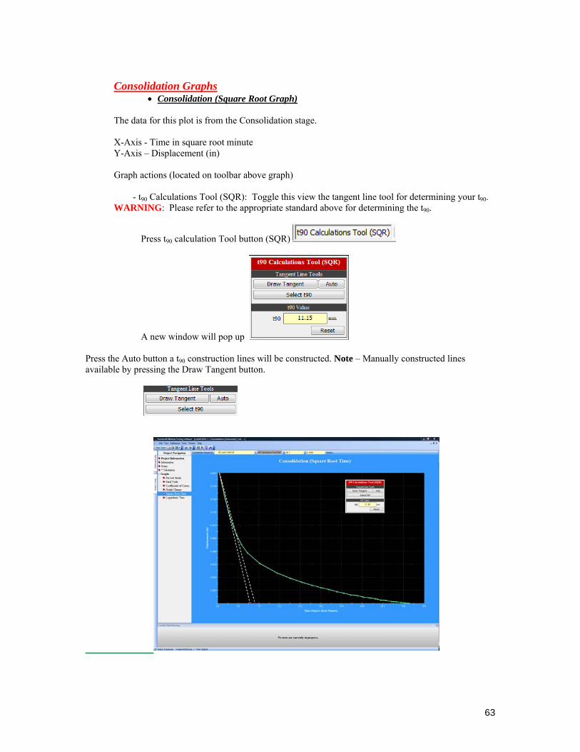
Consolidation Graphs
• Consolidation (Square Root Graph)
The data for this plot is from the Consolidation stage. X-Axis - Time in square root minute Y-Axis – Displacement (in) Graph actions (located on toolbar above graph)
- t90 Calculations Tool (SQR): Toggle this view the tangent line tool for determining your t90.
WARNING: Please refer to the appropriate standard above for determining the t90.
Press t90 calculation Tool button (SQR)
A new window will pop up
Press the Auto button a t90 construction lines will be constructed. Note – Manually constructed lines available by pressing the Draw Tangent button.

64
• Consolidation (Logarithmic Graph)
The data for this plot is from the Consolidation stage. X-Axis - Time in t minute Y-Axis – Displacement (in) Graph actions (located on toolbar above graph)
- t50 Calculations Tool (LOG): Toggle this view the tangent line tool for determining your t50.
WARNING: Please refer to the appropriate standard above for determining the t50.
Press t50 calculation Tool button (LOG)
A new window will pop up

65
Specimen Tabulation
Time = (HHH:MM:SS) Time the point was taken. When running an automated test the time is the elapsed time. Each point contains a time stamp it receives from the hardware. The elapsed time is the difference between the previous data index and the current data index.

66
Specimen Graphs

67

68
Final Stage
1. After final loading increment, stop the test apparatus.
Or press the stop test button and will terminate the test at that time.
2. Remove the normal force from the specimen by removing the mass from the lever loading hanger,
or by releasing the pressure.
3. Remove the ring with specimen and weight. 4. Determine its water content according to Test Method D 2216.
Final Specimen Information
• Final Specimen Reference Height at end of consolidation. • Initial Moisture Content: Calculated – moisture content of specimen. • Initial Specimen Moist Weight + Ring Weight (g) • Final Dry Density - calculated final dry density • Final Wet Density - calculated final wet density • Final Saturation - calculated final saturation value

69
• Final Void Ratio - calculated final void ratio Report