hkkjr ljdkj jsy ea=ky; government of india ministry of...
TRANSCRIPT
Hkkjr ljdkj
jsy ea=ky; GOVERNMENT OF INDIA MINISTRY OF RAILWAYS
vuqla/kku vfHkdYi ,oa ekud laxBu jsy ea=ky;
MANK NAGAR, LUCKNOW-226011
la0 vkj-Mh-,l-vks-@ih-bZ-@,l-ih-bZ-lh-@Vh-,y-@0021&2005 (la’kks- 2)
RDSO Specification No. RDSO/PE/SPEC/TL/0021/2005 (REV ‘2’)
TECHNICAL SPECIFICATION FOR BRUSHLESS DC RAILWAY CARRIAGE FAN Sl.No
. Date of revision
No. of pages
Version Reasons for revision
1. 18.12.2000 13 REV ‘0” First issue 2. 30.11.2005 13 1 To incorporate new material for blades in
line with conventional fan, modify various clauses based on the experience gathered during prototype testing of various make BLDC Fans. To include environmental tests as per IEC-60571 (1998-02) and vibration tests as per IEC-61373(1999)
3. 00.03.2012 2 To improve the reliability by removing sensor magnet and hall sensor including standardization.
vuqeksfnr
Executive Director / PS & EMU
RESEARCH DESIGNS AND STANDARDS ORGANISATION
APPROVED
dk;Zdkjh funs’kd@ih-,l- ,oa bZ-,e-;w-

Page 2 of 2 Effective from RDSO/PE/SPEC/TL/0021/2005 (REV ‘2’)
Prepared by
SSE/PE & Metro
Checked by
ADE/PE & Metro
Re-Checked by
Dir / PE & Metro
TECHNICAL SPECIFICATION FOR BRUSHLESS DC RAILWAY CARRIAGE FAN
0.0 FORWARD:
Previously, 110Vdc fixed and swiveling type fans of different sweeps having commutation with the help of carbon brushes were being used in self-generating coaches and dc EMUs. Maintenance and replacement of carbon brushes & their holders including maintenance of commutator of these fans had been great concern to Indian Railways in addition to its low efficiency, reliability and excess noise. In order to reduce maintenance cost, weight, operational cost and to enhance efficiency, reliability, service life and aesthetic of these fans implementing the latest state of art technology in this filed, this specification for brushless DC railway carriage fan has been prepared for guidance of manufacturers for their design and development.
1.0 REFERENCE TO VARIOUS SPECIFICATIONS
The following publications are applicable to the equipment in general: -
Standards Description IS:6680 Specification for Railway Carriage Fans RDSO Spec No.ELRS/SPEC/SI/0015-Oct-2001
Reliability of Electronics used in rolling stock application
IEC 60571 Electronic Equipment used on Rail vehicles IEC 60571-1 Electronic equipment used on rail vehicles Part 1: General
requirements and tests for electronics equipment IS: 616 Safety requirements for mains operated electronics or
related apparatus for household and similar general use IEC 61373 – 1999 Railway applications –Rolling stock Equipment –Shock &
Vibration tests Note: Latest version of the above specifications/IEC shall be applicable
2.0 SCOPE :
2.1 This specification covers the requirements of design, manufacture, testing and supply of
400mm sweep BLDC railway carriage fans for rolling stock application complete in all respect suitable for input voltage of 110V ac/dc system.
2.2 Electronic controller card shall be used as power devices in the inverter. The inverter
shall have DSP based control and protections with a single controller board for power supply, protection; sinusoidal generation etc. and gate driver card shall be provided closer to the power devices. The detailed specification for DSP and power devices used shall be given/ submitted before offering for witnessing the prototype testing.

Page 3 of 3 Effective from RDSO/PE/SPEC/TL/0021/2005 (REV ‘2’)
Prepared by
SSE/PE & Metro
Checked by
ADE/PE & Metro
Re-Checked by
Dir / PE & Metro
2.3 Input to the unit will be fed through battery bank of 110V dc in parallel with alternator, rectifier cum regulator. The unit shall be suitable for operating voltage available as input i.e. 90V to 140V DC with 15% ripple. The over voltage trip shall be set at 155V
3.0 OPERATING POWER SUPPLY:
The fan shall be suitable for working from the power supply described as under:- Rated Voltage : 110 V DC Voltage range : 90- 140V DC
4.0 DESIGN AND GENERAL CONSTRUCTIONAL FEATURES :
4.1 The motor of the fan shall be permanent magnet type, light in weight and small in size without field winding, brushes and commutator. The stator may be of two or more windings. The permanent magnet shall be fitted on the rotor in such a manner that it should not get disengaged. It is desirable that the magnet shall be embedded in slots. Deep drawn design for fan body made from MS sheet shall conform to RDSO drg. No. RDSO/PE/SK/TL/0025-2002 (Rev.0) Motor body shall be of aluminum alloy LM-6. Details of mounting of fan to coach ceiling are as under.
PCD : 108 mm No. of holes : 3 at equal distance Hole diameter : 9 mm
For fixing of fan guard, extension of fan body collor or provision of additional collor shall be used.
4.2 PROPERTIES FOR PERMANENT MAGNET:
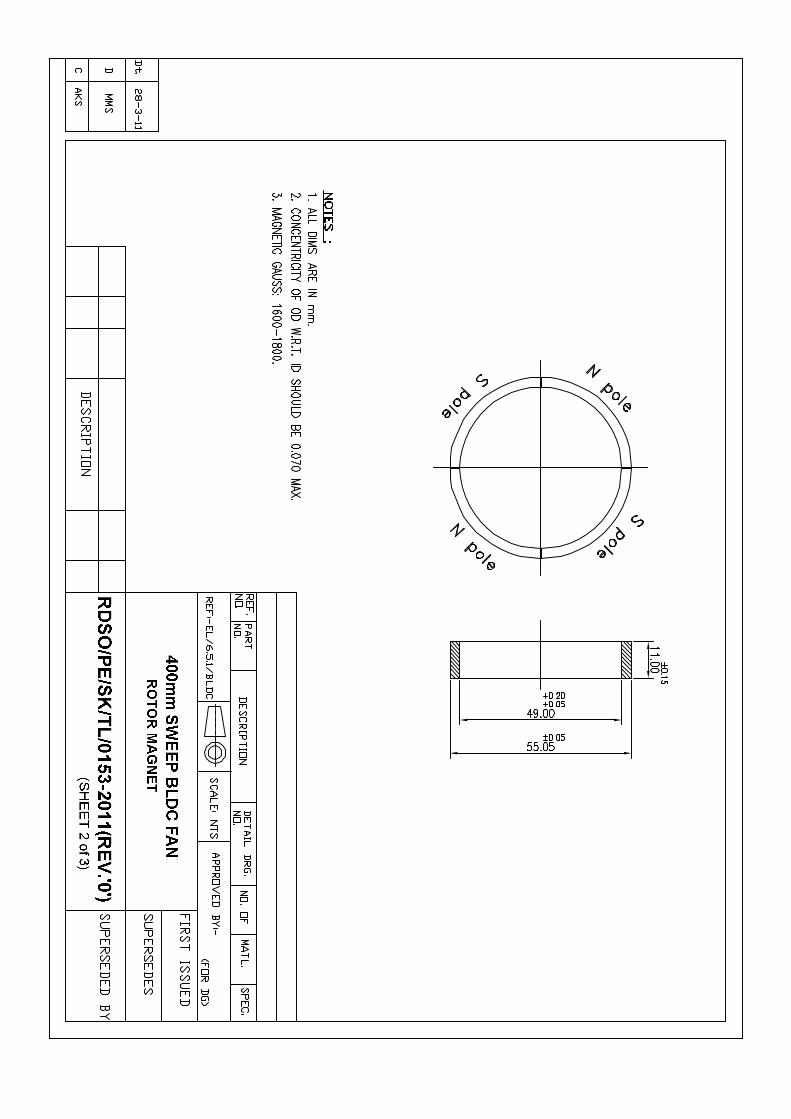
The permanent magnet to be used on the fan shall have the following properties: • Value of coercive force shall be advised after designing the fan • Hardness of the magnet shall not exceed 700 HV • It shall have smooth ground surface. • It shall meet the requirement of clause 8.6 of this specification. • Rotor magnet shall have 1600-1800 Gauss.
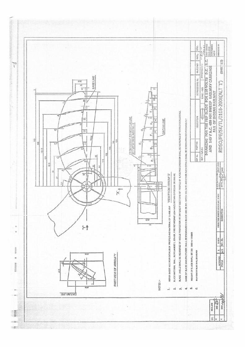
4.3 BLADES:
Fan blades shall conform to RDSO drg. No. RDSO/PE/SK/TL/0108-2008 (ALT ‘1’) (Rev.0) and shall be easily replaceable / interchangeable. The blade shall be made of fire retardant plastic material meeting the following requirements:- § Melting point ASTM D 2177 218°C minimum § Heat deflection temperature under
Page 4 of 4 Effective from RDSO/PE/SPEC/TL/0021/2005 (REV ‘2’)
Prepared by
SSE/PE & Metro
Checked by
ADE/PE & Metro
Re-Checked by
Dir / PE & Metro
load at 1.82 MPa ASTM D648. 180°C minimum § Flammability UL 94 – VO § Tensile strength ASTM D638 MPa 90 MPa minimum § Flexural strength ASTM D790 MPa 130 MPa minimum § Elongation at breaks ASTM D 638 4 - 6% § Impact strength ASTM D 256 A 6.0 kg.-cm/cm minimum § Rockwell hardness ASTM D 785 120 R Scale minimum § Glass filling 30%
4.4 ELECTRONIC CONTROLLER:
Electronic components used in electronic controller or elsewhere in fans shall be as under:
i. IC (Integrated Circuits) shall be of Industrial Grade. ii. Electrolytic capacitors shall be rated for maximum temperature of 105°C (Mill grade/
Industrial grade.) iii. Paper/polyester capacitors shall be rated for maximum temperature of 85°C iv. No Hall Effect sensor shall be used for sensing the rotor position. v. The resistors shall be preferably made of metal film of adequate rating. vi. Switching devices such as transistors, MOSFETs and IGBTs shall have minimum
junction temperature of 150°C. vii. Devices shall have 20°C thermal margin at the ambient of 55°C viii. Material for printed circuit board shall be copper clad glass epoxy of grade FR-4 or
superior. ix. The controller card shall be used with three phase output voltage of 54V with
provision of 6 nos. mounting holes at 1200.
4.4.1 Assembled printed boards shall be given a conformal coating to enable them for functioning under adverse environmental conditions. Over and above the conformal coating, if the firm feels necessary to have potting, they may go for soft potting. However, hard potting under any circumstances may not be acceptable.
4.4.2 Use of surface mounted devices shall be preferred to the maximum possible extent. 4.4.3 No hand soldering shall be allowed. Only automatic wave soldering / reflow soldering is
acceptable. 4.4.4 The supply cable shall not be connected directly to the PCB. Connector (Wago/Phoenix)
shall be soldered to PCB for this purpose. Thin walled flexible elastomeric cables with copper conductors suitable for continuous operation at 120°C and having halogen free insulation and sheath shall be used.
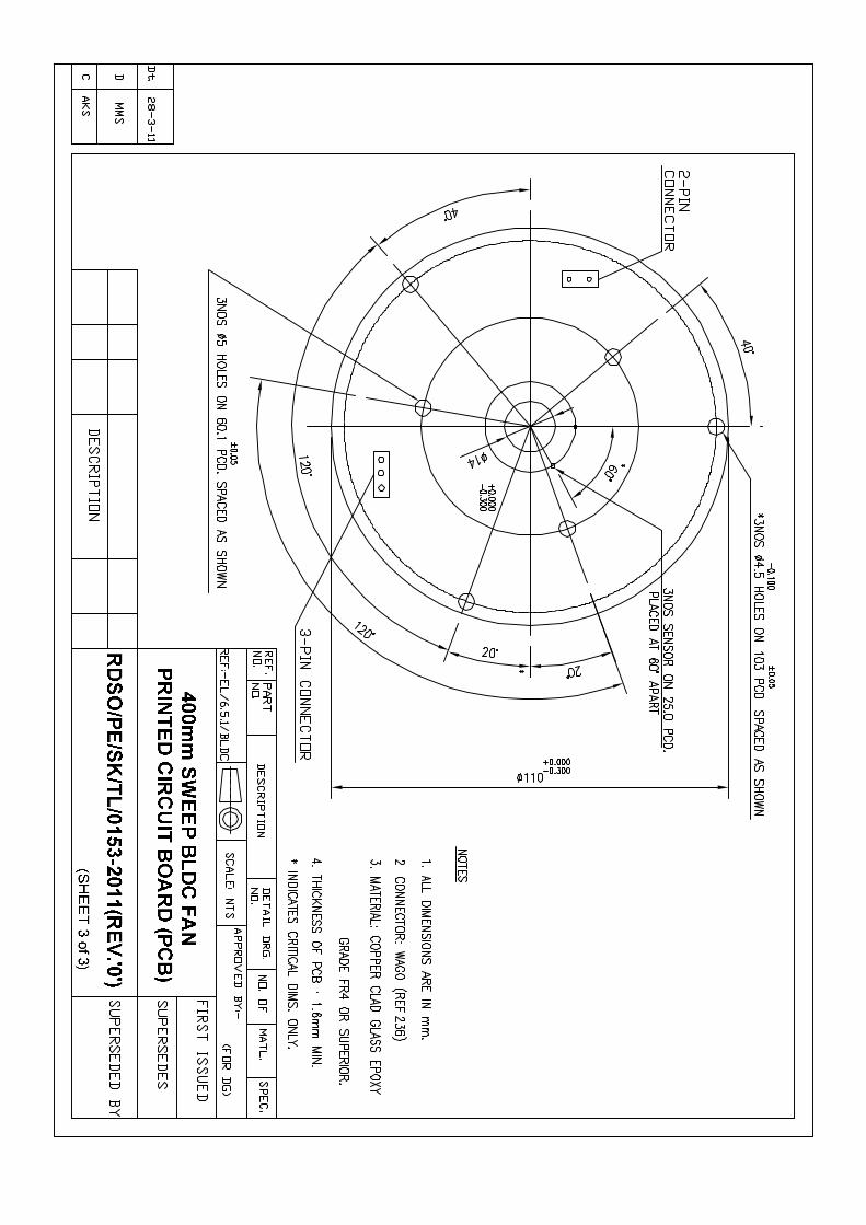
4.4.5 The connector shall be provided as per RDSO drawing no. RDSO/PE/SK/TL/0153-2011
(Rev ‘0’) - sheet 3 of 3 and in such a manner that looking from top of the connector from left side pin, configuration shall be R, Y, B at the output.
Page 5 of 5 Effective from RDSO/PE/SPEC/TL/0021/2005 (REV ‘2’)
Prepared by
SSE/PE & Metro
Checked by
ADE/PE & Metro
Re-Checked by
Dir / PE & Metro
4.5 STAMPINGS:
Laminated core shall be used in the construction of fan motor. The stampings used for laminated yoke and armature core shall be made from electrical steel sheets (see IS: 648, IS: 649 and IS: 3024 with latest amendments if any).
4.6 STATOR Stator used in BLDC fans shall be as under: No. of poles : 3 No. of slots : 6 No. of turns : 435-480 Stack length : 11.5 ±o.5 Stack outer dia : 87 mm Stack inner dia : 56.2 ±0.2
4.7 ROTOR AND ROTOR MAGNET:
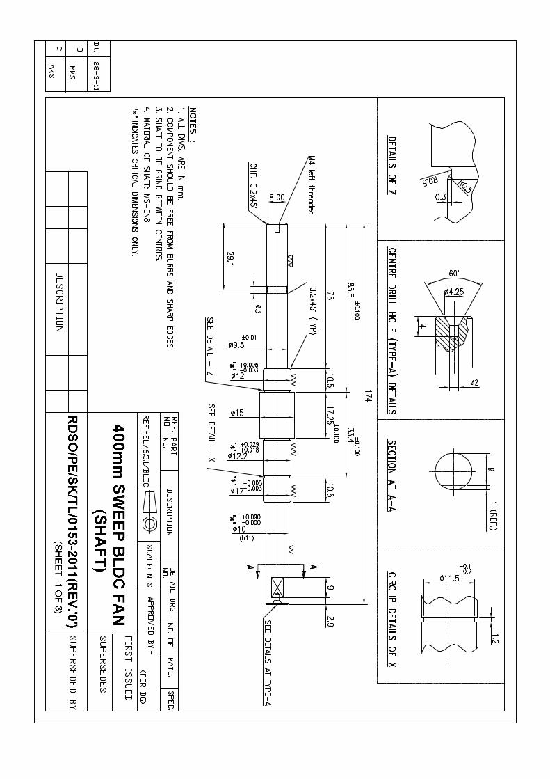
Rotor and rotor magnet used in BLDC fans shall be as per RDSO drawing no. RDSO/PE/SK/ TL/0153-2011 (Rev ‘0’) – sheet 1 of 3 and sheet 2 0f 3 respectively.
4.8 BEARINGS:
SKF make (6201ZZ) ball bearings or equivalent in NBC/ FAG make bearing shall be used.
4.9 WINDING WIRE AND INSULATION:
The copper polyestermide enameled round wire of Class 180 conforming to IS specification NO.13730 (Part 8) shall be used for winding of the motor.
All the insulating materials used in the motor shall be of ISI quality conforming to the relevant specifications and test conditions specified for class 155 insulating materials.
The fan’s motor shall be well treated with the insulating varnish of Class 155 conforming to relevant IS in vacuum pressure impregnation plant to achieve minimum IR value of 20 mega Ω. The curing of varnish shall be done in air circulating oven or as per guidelines issued by varnish manufacturers.
4.10 COLOUR OF FAN BLADE AND BODY:
Complete fan i.e. fan body, motor body, fan guard assembly (of mild steel) etc. shall be powder coated with minimum thickness of 60 microns to colour silver metallic finish to HVC 100 of HAWCOPLAST / 95-03014 of MARPOL. A band of dark yellow colour of about 20 mm wide over the periphery of the fan body approximately at its middle portion shall be applied as a colour code for the fan.
Page 6 of 6 Effective from RDSO/PE/SPEC/TL/0021/2005 (REV ‘2’)
Prepared by
SSE/PE & Metro
Checked by
ADE/PE & Metro
Re-Checked by
Dir / PE & Metro
4.11 GUARD:
Crashworthy design of fan guard shall conform to ICF drg No. ICF/SK-7-6-158 alt. ‘C’.
4.12 GENERAL:
Any more information required, if any, for design, construction and test - IS: 6680 shall be referred to. However, still, if any, clarification is required, RDSO shall be contacted while development. For any deviation while development, firm shall obtain RDSO’s approval. A connector of fiberglass reinforced plastic manufactured from sheet moulding compound (SMC) of 25% fiberglass contents, self-extinguishing grade conforming to RDSO’s drawing no. SKEL-4296 shall be provided. The connector shall be mounted in the ceiling of the coach and shall be supplied separately with the fan.
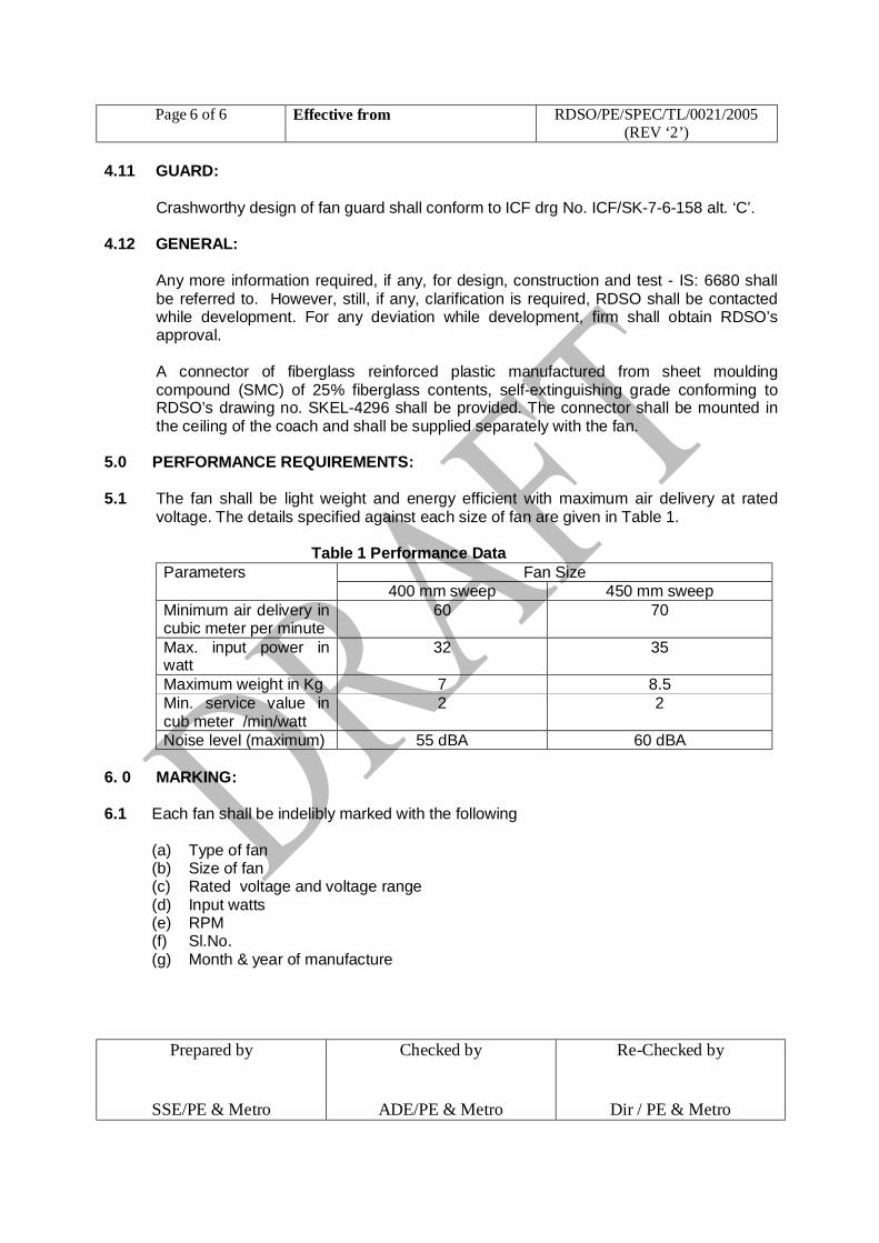
5.0 PERFORMANCE REQUIREMENTS: 5.1 The fan shall be light weight and energy efficient with maximum air delivery at rated
voltage. The details specified against each size of fan are given in Table 1.
Table 1 Performance Data Parameters Fan Size
400 mm sweep 450 mm sweep Minimum air delivery in cubic meter per minute
60 70
Max. input power in watt
32 35
Maximum weight in Kg 7 8.5 Min. service value in cub meter /min/watt
2 2
Noise level (maximum) 55 dBA 60 dBA 6. 0 MARKING: 6.1 Each fan shall be indelibly marked with the following
(a) Type of fan (b) Size of fan (c) Rated voltage and voltage range (d) Input watts (e) RPM (f) Sl.No. (g) Month & year of manufacture
Page 7 of 7 Effective from RDSO/PE/SPEC/TL/0021/2005 (REV ‘2’)
Prepared by
SSE/PE & Metro
Checked by
ADE/PE & Metro
Re-Checked by
Dir / PE & Metro
6.2 An oval shape rectangular plate of size 50 mm x 30 mm fixed by two screws or rivets shall be provided on the fan motor for marking of Railway Code initials and serial Number separately.
7.0 TESTS: 7.1 Type tests shall be carried out by RDSO on five samples of BLDC fans of the same type
selected from the lot available at the premises of the manufacturers. One fan shall used for endurance tests after carrying out all tests except tests mentioned at clause 8.9. However temperature of Insulated windings, accessible external surface metallic / non-metallic, bearings shall be recorded at the end of the endurance test and shall not exceed the limits given in Table at clause 8.9. In respect of tests for which testing facility is not available with the manufacturer, the same may be carried out at NABL accredited test house / lab and test reports shall be submitted to RDSO.
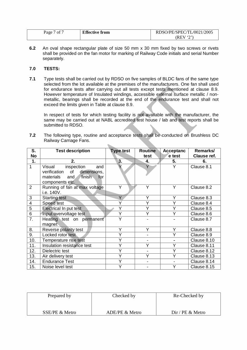
7.2 The following type, routine and acceptance tests shall be conducted on Brushless DC
Railway Carriage Fans. S. No
Test description Type test Routine test
Acceptance test
Remarks/ Clause ref.
1. 2. 3. 4. 5. 6. 1 Visual inspection and
verification of dimensions, materials and finish for components etc.
Y Y Y Clause 8.1
2 Running of fan at max voltage i.e. 140V.
Y Y Y Clause 8.2
3 Starting test Y Y Y Clause 8.3 4 Speed test Y Y Y Clause 8.4 5 Electrical In put test Y Y Y Clause 8.5 6 Input overvoltage test Y Y Y Clause 8.6 7. Heating test on permanent
magnet Y - - Clause 8.7
8. Reverse polarity test Y Y Y Clause 8.8 9. Locked rotor test Y - Y Clause 8.9 10. Temperature rise test Y - - Clause 8.10 11. Insulation resistance test Y Y Y Clause 8.11 12. Dielectric test Y - Y Clause 8.12 13. Air delivery test Y Y Y Clause 8.13 14. Endurance Test Y - - Clause 8.14 15. Noise level test Y - Y Clause 8.15
Page 8 of 8 Effective from RDSO/PE/SPEC/TL/0021/2005 (REV ‘2’)
Prepared by
SSE/PE & Metro
Checked by
ADE/PE & Metro
Re-Checked by
Dir / PE & Metro
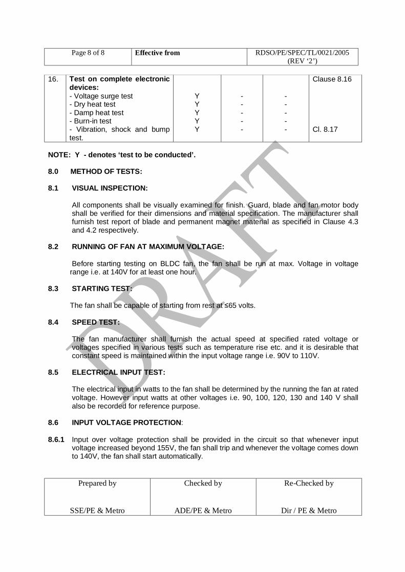
16. Test on complete electronic devices: - Voltage surge test - Dry heat test - Damp heat test - Burn-in test - Vibration, shock and bump test.
Y Y Y Y Y
- - - - -
- - - - -
Clause 8.16 Cl. 8.17
NOTE: Y - denotes ‘test to be conducted’. 8.0 METHOD OF TESTS: 8.1 VISUAL INSPECTION:
All components shall be visually examined for finish. Guard, blade and fan motor body shall be verified for their dimensions and material specification. The manufacturer shall furnish test report of blade and permanent magnet material as specified in Clause 4.3 and 4.2 respectively.
8.2 RUNNING OF FAN AT MAXIMUM VOLTAGE:
Before starting testing on BLDC fan, the fan shall be run at max. Voltage in voltage range i.e. at 140V for at least one hour.
8.3 STARTING TEST:
The fan shall be capable of starting from rest at ≤65 volts.
8.4 SPEED TEST:
The fan manufacturer shall furnish the actual speed at specified rated voltage or voltages specified in various tests such as temperature rise etc. and it is desirable that constant speed is maintained within the input voltage range i.e. 90V to 110V.
8.5 ELECTRICAL INPUT TEST:
The electrical input in watts to the fan shall be determined by the running the fan at rated voltage. However input watts at other voltages i.e. 90, 100, 120, 130 and 140 V shall also be recorded for reference purpose.
8.6 INPUT VOLTAGE PROTECTION:
8.6.1 Input over voltage protection shall be provided in the circuit so that whenever input voltage increased beyond 155V, the fan shall trip and whenever the voltage comes down to 140V, the fan shall start automatically.
Page 9 of 9 Effective from RDSO/PE/SPEC/TL/0021/2005 (REV ‘2’)
Prepared by
SSE/PE & Metro
Checked by
ADE/PE & Metro
Re-Checked by
Dir / PE & Metro
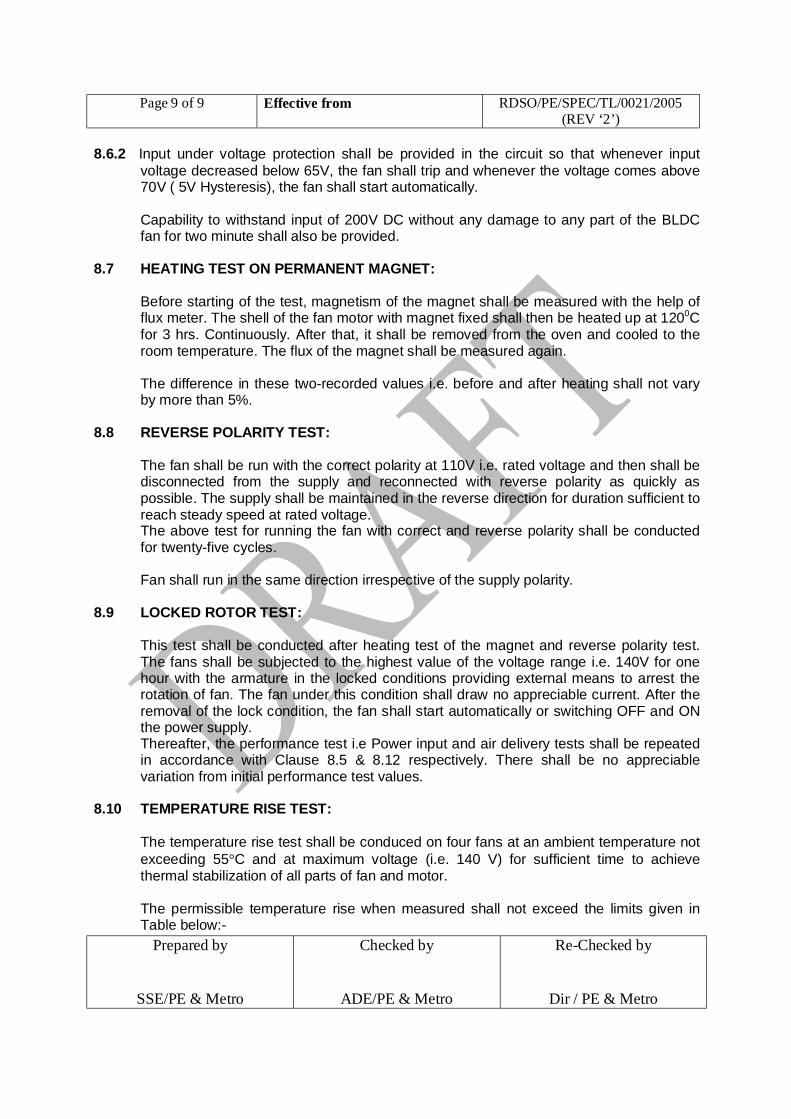
8.6.2 Input under voltage protection shall be provided in the circuit so that whenever input voltage decreased below 65V, the fan shall trip and whenever the voltage comes above 70V ( 5V Hysteresis), the fan shall start automatically. Capability to withstand input of 200V DC without any damage to any part of the BLDC fan for two minute shall also be provided.
8.7 HEATING TEST ON PERMANENT MAGNET:
Before starting of the test, magnetism of the magnet shall be measured with the help of flux meter. The shell of the fan motor with magnet fixed shall then be heated up at 1200C for 3 hrs. Continuously. After that, it shall be removed from the oven and cooled to the room temperature. The flux of the magnet shall be measured again. The difference in these two-recorded values i.e. before and after heating shall not vary by more than 5%.
8.8 REVERSE POLARITY TEST:
The fan shall be run with the correct polarity at 110V i.e. rated voltage and then shall be disconnected from the supply and reconnected with reverse polarity as quickly as possible. The supply shall be maintained in the reverse direction for duration sufficient to reach steady speed at rated voltage. The above test for running the fan with correct and reverse polarity shall be conducted for twenty-five cycles.
Fan shall run in the same direction irrespective of the supply polarity. 8.9 LOCKED ROTOR TEST:
This test shall be conducted after heating test of the magnet and reverse polarity test. The fans shall be subjected to the highest value of the voltage range i.e. 140V for one hour with the armature in the locked conditions providing external means to arrest the rotation of fan. The fan under this condition shall draw no appreciable current. After the removal of the lock condition, the fan shall start automatically or switching OFF and ON the power supply. Thereafter, the performance test i.e Power input and air delivery tests shall be repeated in accordance with Clause 8.5 & 8.12 respectively. There shall be no appreciable variation from initial performance test values.
8.10 TEMPERATURE RISE TEST: The temperature rise test shall be conduced on four fans at an ambient temperature not
exceeding 55°C and at maximum voltage (i.e. 140 V) for sufficient time to achieve thermal stabilization of all parts of fan and motor. The permissible temperature rise when measured shall not exceed the limits given in Table below:-
Page 10 of 10 Effective from RDSO/PE/SPEC/TL/0021/2005 (REV ‘2’)
Prepared by
SSE/PE & Metro
Checked by
ADE/PE & Metro
Re-Checked by
Dir / PE & Metro
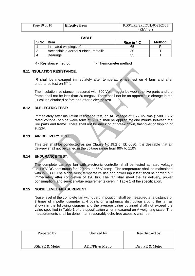
TABLE S.No Item Rise in ° C Method 1 Insulated windings of motor 65 R 3 Accessible external surface, metallic 30 T 4 Bearings 35 T
R - Resistance method T - Thermometer method
8.11 INSULATION RESISTANCE: IR shall be measured immediately after temperature rise test on 4 fans and after endurance test on 5th fan. The insulation resistance measured with 500 Volt megger between the live parts and the frame shall not be less than 20 megaΩ. There shall not be an appreciable change in the IR values obtained before and after dielectric test.
8.12 DI-ELECTRIC TEST:
Immediately after insulation resistance test, an AC voltage of 1.72 KV rms (1500 + 2 x rated voltage) of sine wave form of 50 Hz shall be applied for one minute between the live parts and frame. There shall not be any kind of break down, flashover or tripping of supply.
8.13 AIR DELIVERY TEST:
This test shall be conducted as per Clause No.19.2 of IS: 6680. It is desirable that air delivery shall not be varied in the voltage range from 90V to 110V.
8.14 ENDURANCE TEST:
The complete carriage fan with electronic controller shall be tested at rated voltage i.e.110V DC continuous for 120 hrs. at 55°C temp.. The temperature shall be maintained with in ± 3°C. The air delivery, temperature rise and power input test shall be carried out immediately after completion of 120 hrs. The fan shall meet the air delivery, power consumption, and service value requirements given in Table 1 of the specification.
8.15 NOISE LEVEL MEASUREMENT:
Noise level of the complete fan with guard in position shall be measured at a distance of 3 times of impeller diameter at 4 points on a spherical distribution around the fan as shown in the following diagram and the average value obtained shall not exceed the value specified in Table 1 of the specification when measured on A weighting scale. The measurements shall be done in an reasonably echo free acoustic chamber.

Page 11 of 11 Effective from RDSO/PE/SPEC/TL/0021/2005 (REV ‘2’)
Prepared by
SSE/PE & Metro
Checked by
ADE/PE & Metro
Re-Checked by
Dir / PE & Metro
fan 1 4
45° 45° 2 3 8.16 ENVIRONMENTAL TEST ON COMPLETE ELECTRONIC DEVICES:
These tests shall be conducted on the complete electronic devices such as card, electronic controllers used for commutation in the Carriage Fans as per the standard specified against each test. i) Voltage surge test - Clause5.4 of IEC 571-1 ii) Dry Heat test * - Clause 10.2.4 of IEC 60571 iii) Damp Heat test - Clause 10.2.5 of IEC 60571 iv) Burn-in test - Clause no. 7.7 of RDSO Spec No.ELRS
/ SPEC/SI/0015-Oct-2001 * However, dry heat test shall be conducted at 80°C.
8.17 VIBRATION, SHOCK AND BUMP TEST
The test shall be conducted in accordance with the relevant clauses of IEC 61373 for category 1- Class A. No mechanical damage or deterioration in performance shall occur as a result of these tests.
9.0 SAMPLING PLAN FOR ACCEPTANCE TEST:
Method for sampling of fans for conducting acceptance tests shall be as per Annexure D Table 3 (Clause 19.1.2.1) of IS: 6680.
10.0 DEVIATIONS:
Any deviation to this specification proposed by the manufacturer, aimed to improve upon the performance, utility and reliability/efficiency of the equipment shall be given due consideration, provided full particulars of the deviations with justification are furnished.
11.0 INFRINGEMENT OF PATENT RIGHT:
Indian Railway shall not be responsible for infringement of patent rights arising due to similarity in design, manufacturing process, used of components in design/development/manufacturing of Brushless dc fan and/or any other factor, which may cause such dispute. The responsibility to settle any such issue will rest with the manufacturer.

Page 12 of 12 Effective from RDSO/PE/SPEC/TL/0021/2005 (REV ‘2’)
Prepared by
SSE/PE & Metro
Checked by
ADE/PE & Metro
Re-Checked by
Dir / PE & Metro
12.0 TECHNICAL INFORMATION:
The manufacturers shall supply the following technical information in respect of Brushless dc fan. v) Rated speed in rev/min.
vi) Air delivery & service value at rated voltage i.e. 110 V DC.
vii) Number of blades and their detailed drawing with material specification along with the test report.
viii) Class and details of winding insulation & insulating varnish.
ix) Type, make and life etc. of bearings.
x) Instructions for lubrication of bearings.
xi) Details of magnet characteristics.
xii) Weight of fan.
xiii) Drawings showing the overall dimensions of the fan including Motor unit with mounting dimensions.
xiv) Drawings showing full particulars of the armature/rotor and stator windings including dimensions, shape, size, section and weight of copper wire used.
xv) Technical details with drg/schematic of electronic controller card. 13.0 INFRASTRUCTURE & ESSENTIAL TESTING EQUIPMENTS In respect of machinery and plant considered essential for the manufacture of quality
and reliable product, essential testing / measuring equipments and eligibility criteria etc., the manufacturer shall fulfill the requirements of latest STR No. RDSO/PE/STR/TL/0016-2005 (Rev. ‘0’) issued by RDSO for BLDC fan. *********


t..
T~
Elltw!