hiwin general - cnc4youcnc4you.co.uk/resources/hiwin general.pdf(1) hgh-ca / hgh-ha note : 1 kgf =...
TRANSCRIPT

Hiwin General
INFORMATION IS SPECIFIC TO OUR PRODUCTS AND CAN CAUSE
DAMAGE IF USED WITH NONE COMPATIBLE PRODUCTS SO PLEASE
CHECK WITH YOUR SUPPLIER FOR COMPATIBILITY
© CNC4YOU LTD ALL RIGHTS RESERVED
These drawings are supplied as a guide no guarantees are implied or given.Caution when wiring and check with a qualified professional if unsure.
Documentation will be updated amended at the discretion of CNC4YOU Ltd.
V1.00

Linear GuidewaysHG Series
Rolling circulation system: Block, Rail, End Cap and Retainer
Lubrication system: Grease Nipple and Piping Joint
Dust protection system: End seal, Bottom Seal, Bolt Cap, Double Seals and Scraper
2-1 HG Series - Heavy Load Ball Type Linear Guideway
2-1-3 Model Number of HG SeriesHG series guideways can be classified into non-interchangeable and interchangeable types. The sizes are identical. The only difference between the two types is that the interchangeable type of blocks and rails can be freely exchanged, and their accuracy can reach up to P class. The model number of HG series contains the size, type, accuracy class, preload class, etc..
2-1-1 Features of HG Series (1) Self-aligning capability By design, the circular-arc groove has contact points at 45 degrees. HG series can absorb most installation errors due to surface irregularities and provide smooth linear motion through the elastic deformation of rolling elements and the shift of contact points. Self-aligning capability, high accuracy and smooth operation can be obtained with an easy installation.
(2) Interchangeability Because of precision dimensional control, the dimensional tolerance of HG series can be kept in a reasonable range, which means that any blocks and any rails in a specific series can be used together while maintaining dimensional tolerance. And a retainer is added to prevent the balls from falling out when the blocks are removed from the rail.
(3) High rigidity in all four directions Because of the four-row design, the HG series linear guideway has equal load ratings in the radial, reverse radial and lateral directions. Furthermore, the circular-arc groove provides a wide-contact width between the balls and the groove raceway allowing large permissible loads and high rigidity.
Block
End seal(Double seals and scraper)
Grease nipple
End capRail
Bolt cap
Retainer
Bottom seal
Ball
HG series linear guideways are designed with load capacity and rigidity higher than other similar products with circular-arc groove and structure optimization. It features equal load ratings in the radial, reverse radial and lateral directions, and self-aligning to absorb installation-error. Thus, HIWIN HG series linear guideways can achieve a long life with high speed, high accuracy and smooth linear motion.
2-1-2 Construction of HG Series
G99TE15-1104
Tel: 01908 315011 07576759884
P
N
H
h
E
Ød
W
B
T
4-Mxl
ØD
G L
E
C
K1
L1K2
H3
H2
HR
H1
B1
WR
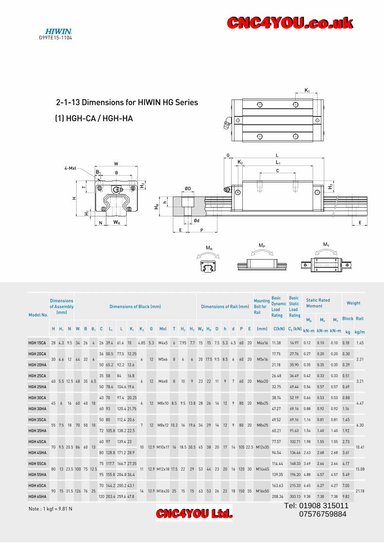
(1) HGH-CA / HGH-HA
Note : 1 kgf = 9.81 N
2-1-13 Dimensions for HIWIN HG Series
Model No.
Dimensions
of Assembly
(mm)
Dimensions of Block (mm) Dimensions of Rail (mm)
Mounting
Bolt for
Rail
Basic
Dynamic
Load
Rating
Basic
Static
Load
Rating
Static Rated
MomentWeight
MR
kN-m
MP
kN-m
MY
kN-m
Block
kg
Rail
kg/mH H1 N W B B1 C L1 L K1 K2 G Mxl T H2 H3 WR HR D h d P E (mm) C(kN) C0 (kN)
HGH 15CA 28 4.3 9.5 34 26 4 26 39.4 61.4 10 4.85 5.3 M4x5 6 7.95 7.7 15 15 7.5 5.3 4.5 60 20 M4x16 11.38 16.97 0.12 0.10 0.10 0.18 1.45
HGH 20CA
30 4.6 12 44 32 6
36 50.5 77.5 12.25
6 12 M5x6 8 6 6 20 17.5 9.5 8.5 6 60 20 M5x16
17.75 27.76 0.27 0.20 0.20 0.30
2.21
HGH 20HA 50 65.2 92.2 12.6 21.18 35.90 0.35 0.35 0.35 0.39
HGH 25CA
40 5.5 12.5 48 35 6.5
35 58 84 16.8
6 12 M6x8 8 10 9 23 22 11 9 7 60 20 M6x20
26.48 36.49 0.42 0.33 0.33 0.51
3.21
HGH 25HA 50 78.6 104.6 19.6 32.75 49.44 0.56 0.57 0.57 0.69
HGH 30CA
45 6 16 60 40 10
40 70 97.4 20.25
6 12 M8x10 8.5 9.5 13.8 28 26 14 12 9 80 20 M8x25
38.74 52.19 0.66 0.53 0.53 0.88
4.47
HGH 30HA 60 93 120.4 21.75 47.27 69.16 0.88 0.92 0.92 1.16
HGH 35CA
55 7.5 18 70 50 10
50 80 112.4 20.6
7 12 M8x12 10.2 16 19.6 34 29 14 12 9 80 20 M8x25
49.52 69.16 1.16 0.81 0.81 1.45
6.30
HGH 35HA 72 105.8 138.2 22.5 60.21 91.63 1.54 1.40 1.40 1.92
HGH 45CA
70 9.5 20.5 86 60 13
60 97 139.4 23
10 12.9 M10x17 16 18.5 30.5 45 38 20 17 14 105 22.5 M12x35
77.57 102.71 1.98 1.55 1.55 2.73
10.41
HGH 45HA 80 128.8 171.2 28.9 94.54 136.46 2.63 2.68 2.68 3.61
HGH 55CA
80 13 23.5 100 75 12.5
75 117.7 166.7 27.35
11 12.9 M12x18 17.5 22 29 53 44 23 20 16 120 30 M14x45
114.44 148.33 3.69 2.64 2.64 4.17
15.08
HGH 55HA 95 155.8 204.8 36.4 139.35 196.20 4.88 4.57 4.57 5.49
HGH 65CA
90 15 31.5 126 76 25
70 144.2 200.2 43.1
14 12.9 M16x20 25 15 15 63 53 26 22 18 150 35 M16x50
163.63 215.33 6.65 4.27 4.27 7.00
21.18
HGH 65HA 120 203.6 259.6 47.8 208.36 303.13 9.38 7.38 7.38 9.82
G99TE15-1104
Tel: 01908 315011 07576759884
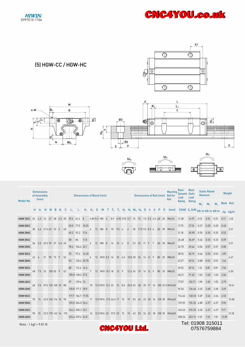
(5) HGW-CC / HGW-HC
P
ØDT
H
N Ød
E
hW
B4-M
G L
E
C
K1
H2
T2
T1
H1
HR
H3
B1
WR
L1K2
Note : 1 kgf = 9.81 N
Model No.
Dimensions
of Assembly
(mm)
Dimensions of Block (mm) Dimensions of Rail (mm)
Mounting
Bolt for
Rail
Basic
Dynamic
Load
Rating
Basic
Static
Load
Rating
Static Rated
MomentWeight
MR
kN-m
MP
kN-m
MY
kN-m
Block
kg
Rail
kg/mH H1 N W B B1 C L1 L K1 K2 G M T T1 T2 H2 H3 WR HR D h d P E (mm) C(kN) C0 (kN)
HGW 15CC 24 4.3 16 47 38 4.5 30 39.4 61.4 8 4.85 5.3 M5 6 8.9 6.95 3.95 3.7 15 15 7.5 5.3 4.5 60 20 M4x16 11.38 16.97 0.12 0.10 0.10 0.17 1.45
HGW 20CC
30 4.6 21.5 63 53 5 40
50.5 77.5 10.25
6 12 M6 8 10 9.5 6 6 20 17.5 9.5 8.5 6 60 20 M5x16
17.75 27.76 0.27 0.20 0.20 0.40
2.21
HGW 20HC 65.2 92.2 17.6 21.18 35.90 0.35 0.35 0.35 0.52
HGW 25CC
36 5.5 23.5 70 57 6.5 45
58 84 11.8
6 12 M8 8 14 10 6 5 23 22 11 9 7 60 20 M6x20
26.48 36.49 0.42 0.33 0.33 0.59
3.21
HGW 25HC 78.6 104.6 22.1 32.75 49.44 0.56 0.57 0.57 0.80
HGW 30CC
42 6 31 90 72 9 52
70 97.4 14.25
6 12 M10 8.5 16 10 6.5 10.8 28 26 14 12 9 80 20 M8x25
38.74 52.19 0.66 0.53 0.53 1.09
4.47
HGW 30HC 93 120.4 25.75 47.27 69.16 0.88 0.92 0.92 1.44
HGW 35CC
48 7.5 33 100 82 9 62
80 112.4 14.6
7 12 M10 10.1 18 13 9 12.6 34 29 14 12 9 80 20 M8x25
49.52 69.16 1.16 0.81 0.81 1.56
6.30
HGW 35HC 105.8 138.2 27.5 60.21 91.63 1.54 1.40 1.40 2.06
HGW 45CC
60 9.5 37.5 120 100 10 80
97 139.4 13
10 12.9 M12 15.1 22 15 8.5 20.5 45 38 20 17 14 105 22.5 M12x35
77.57 102.71 1.98 1.55 1.55 2.79
10.41
HGW 45HC 128.8 171.2 28.9 94.54 136.46 2.63 2.68 2.68 3.69
HGW 55CC
70 13 43.5 140 116 12 95
117.7 166.7 17.35
11 12.9 M14 17.5 26.5 17 12 19 53 44 23 20 16 120 30 M14x45
114.44 148.33 3.69 2.64 2.64 4.52
15.08
HGW 55HC 155.8 204.8 36.4 139.35 196.20 4.88 4.57 4.57 5.96
HGW 65CC
90 15 53.5 170 142 14 110
144.2 200.2 23.1
14 12.9 M16 25 37.5 23 15 15 63 53 26 22 18 150 35 M16x50
163.63 215.33 6.65 4.27 4.27 9.17
21.18
HGW 65HC 203.6 259.6 52.8 208.36 303.13 9.38 7.38 7.38 12.89
G99TE15-1104
Tel: 01908 315011 07576759884

Linear GuidewaysHG Series
Item HG15 HG20 HG25 HG30 HG35 HG45 HG55 HG65
Standard Length L(n)
160 (3) 220 (4) 220 (4) 280 (4) 280 (4) 570 (6) 780 (7) 1,270 (9)
220 (4) 280 (5) 280 (5) 440 (6) 440 (6) 885 (9) 1,020 (9) 1,570 (11)
280 (5) 340 (6) 340 (6) 600 (8) 600 (8) 1,200 (12) 1,260 (11) 2,020 (14)
340 (6) 460 (8) 460 (8) 760 (10) 760 (10) 1,620 (16) 1,500 (13) 2,620 (18)
460 (8) 640 (11) 640 (11) 1,000 (13) 1,000 (13) 2,040 (20) 1,980 (17)
640 (11) 820 (14) 820 (14) 1,640 (21) 1,640 (21) 2,460 (24) 2,580 (22)
820 (14) 1,000 (17) 1,000 (17) 2,040 (26) 2,040 (26) 2,985 (29) 2,940 (25)
1,240 (21) 1,240 (21) 2,520 (32) 2,520 (32)
1,600 (27) 3,000 (38) 3,000 (38)
Pitch (P) 60 60 60 80 80 105 120 150
Distance to End (Es) 20 20 20 20 20 22.5 30 35
Max. Standard Length 1,960 (33) 4,000 (67) 4,000 (67) 3,960 (50) 3,960 (50) 3,930 (38) 3,900 (33) 3,970 (27)
Max. Length 2,000 4,000 4,000 4,000 4,000 4,000 4,000 4,000
n=(Number of rail mounting holes)
Table 2-1-24 Rail Standard Length and Max. Length
L : Total length of rail (mm)n : Number of mounting holesP : Distance between any two holes (mm)E : Distance from the center of the last hole to the edge (mm)
2-1-12 Standard and Maximum Lengths of Rail
Eq.2.1=(n-1) L P + 2x x E
HIWIN offers standard rail lengths for customer needs. For non-standard E-values, the recommended dimension should not be greater than 1/2 of the pitch (P) dimension. This will prevent an unstable rail end.
unit: mm
Note : 1. Tolerance of E value for standard rail is 0.5~-0.5 mm. Tolerance of E value for jointed rail is 0~-0.3 mm. 2. Maximum standard length means the max. rail length with standard E value on both sides.
3. If different E value is needed, please contact HIWIN.
G99TE15-1104
Tel: 01908 315011 07576759884